

Page 1
IM 12B6K1-01E-E
6st edition
Instruction
Manual
Model FF20
Flow fittings
Model FS20
Subassembly flow fittings
Page 2

IM 12B6K1-01E-E
1. INTRODUCTION..........................................................................................................1
1-1.General .................................................................................................................1
1-2.Features................................................................................................................1
2. UNPACKING AND CHECKING ..................................................................................1
2-1.Unpacking and inspection.....................................................................................1
2-2.Mounting location .................................................................................................1
2-3.Specifications........................................................................................................2
2-3-1. General specifications ................................................................................2
2-3-2. Functional specifications ............................................................................3
2-4.Model and codes..................................................................................................4
2-4-1. Flow fittings................................................................................................4
2-4-2. Subassemblies...........................................................................................5
2-5.Dimensions ...........................................................................................................6
2-5-1. Fittings .......................................................................................................6
2-5-2. Subassemblies...........................................................................................7
3. PIPING AND INSTALLATION .....................................................................................8
3-1.General .................................................................................................................8
3-2.Piping ...................................................................................................................8
3-2-1. Mounting in a sample line...........................................................................8
3-2-2. Mounting in a shunt line .............................................................................8
3-2-3. Mounting in a sample line with extra connection for liquid cleanser............9
3-3.Installation.............................................................................................................9
3-3-1. Mounting for fitting .....................................................................................9
3-3-2 Mounting the subassembly .......................................................................10
3-4.Sensor mounting ................................................................................................10
3-4-1. General ....................................................................................................10
3-4-2. Mounting in a 1-hole design.....................................................................11
3-4-2. Mounting in a 3- and 4-hole design .........................................................11
4. ACCESSORIES..........................................................................................................11
4-1.General ...............................................................................................................11
4-2.Mounting kit for BELLOMATIC electrodes...........................................................11
4-3.Mounting kit for sterilisable applicaitons ..............................................................12
4-4.Mounting kit for top refillable electrodes..............................................................13
4-5.Cleaning systems................................................................................................13
4-5-1. General ....................................................................................................13
4-5-2. Selection criteria.......................................................................................14
4-5-3. Mechanical cleaning.................................................................................14
4-5-4. Chemical cleaning ....................................................................................15
4-6.Salt bridge ..........................................................................................................16
5. MAINTENANCE
.........................................................................................................17
5-1.General ...............................................................................................................17
5-2.
Cleaning
..............................................................................................................17
5-3.Calibration...........................................................................................................18
5-4.
Replacing the O-rings
.........................................................................................
18
6. EXPLODED VIEW......................................................................................................19
7. SPARE PARTS LIST..................................................................................................21
Page 3
1. INTRODUCTION
1-1. General
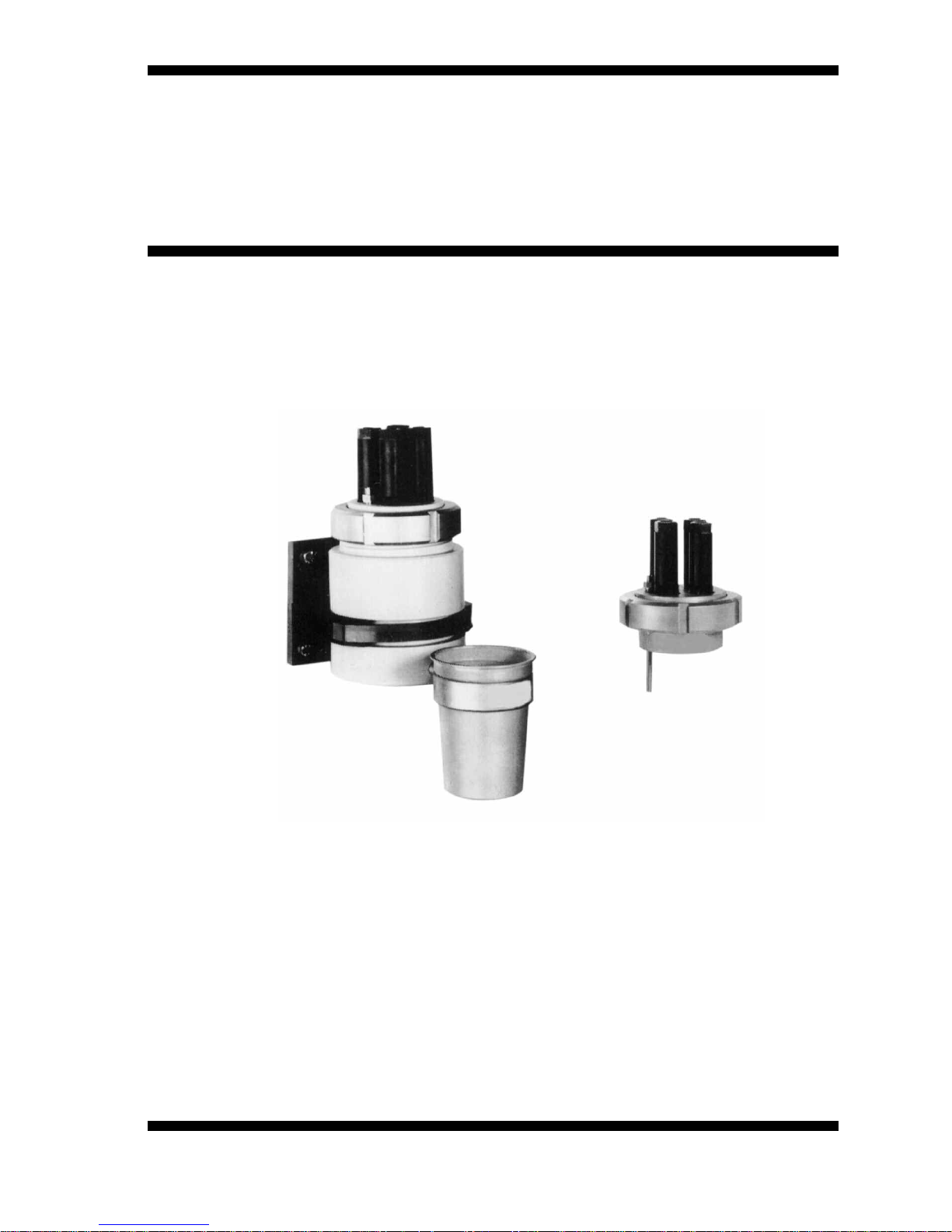
The flow fittings (Model FF20) and their subassemblies (Model FS20) are used to mount
sensor tips in a piping system so that the pH and/or the ORP (Redox) potential of the liquid
flowing through it can be measured.
The flow fittings are for connection between two pipes of the piping system providing a
“flow through” path. From a practical plant aspect (for easy maintenance and calibration)
the mounting place is in a by-pass behind a sample valve. They are supplied with a ring to
hold calibration dish for this cleaning and/or calibration.
The subassemblies should be cemented or welded direct in the piping system or in a
T-piece of it. The subassemblies of stainless steel meet the requirements of DIN 11850
for mounting in sanitary constructions.
1-2. Features
- Wide choice fo construction materials.
- High degree fo standardisation reduces spare holding requirements.
- Direct mounting of sensors with DIN dimensions.
- Liquid earth sensor for stable measurements.
- High pressure and temperature specifications.
- Chemical or brush cleaning (optional in 4-hole fittings).
2. UNPACKING AND CHECKING
2-1. Unpacking and inspection
When you receive the flow fitting (Model FF20) or the subassembly flow fitting (Model FS20)
it is packed in a cardboard box. Open the box and check that the model code is the same
as on the packing list (see §2-3 for the model code). Also check that it is supplied with the
options you ordered. These options are delivered in seperate bags.
If you have any problems or questions, please contact the nearest Yokogawa service
center or sales organisation for assistance.
2-2. Mounting location
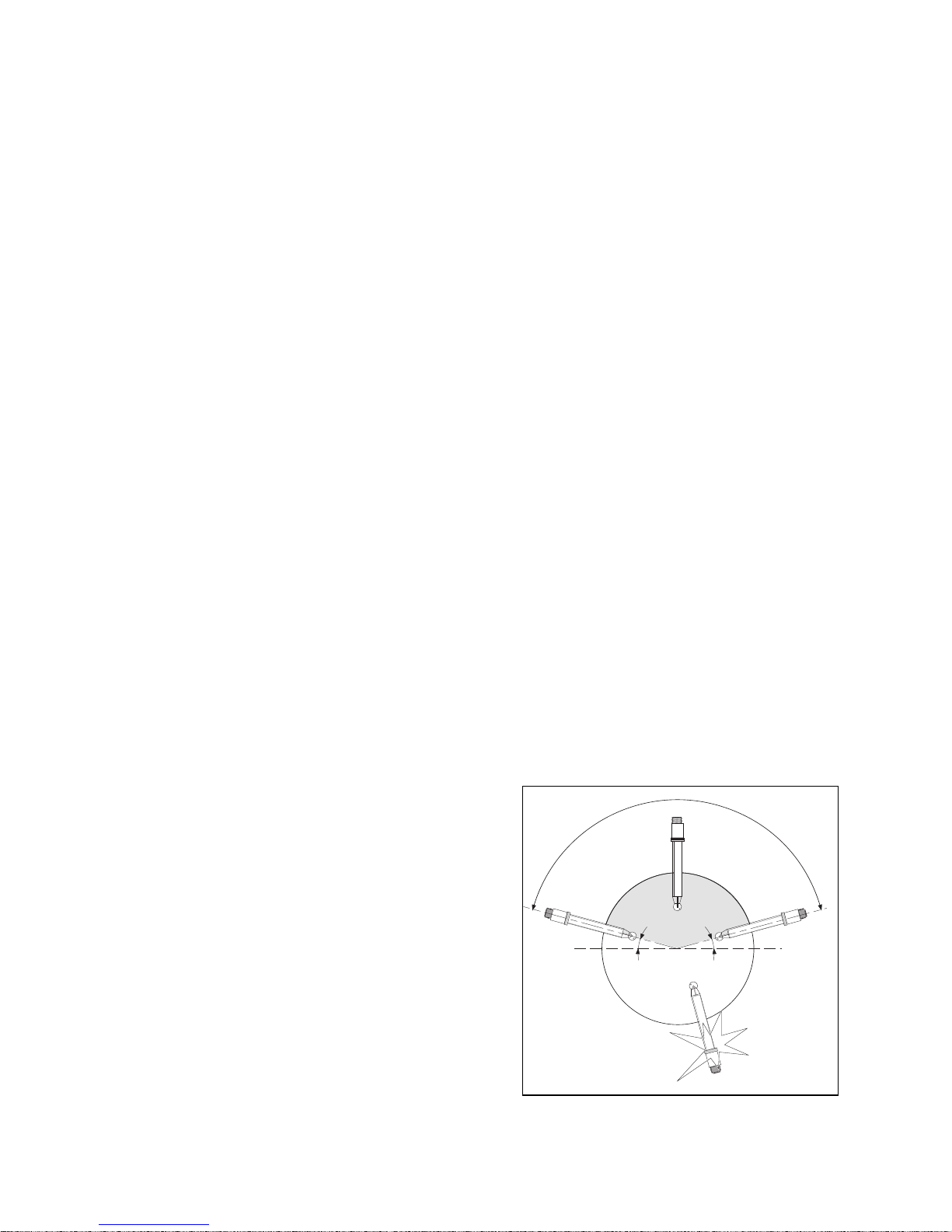
The flow fitting or subassembly flow fitting is
intended to be used for pH and/or ORP
(Redox) measurement. The location should be
in a bypass of a piping system behind a
sample valve. The angle of the fitting with the
horizontal should be less than 15°
(see fig. 2-1).
The pressure and temperature ratings of the
electrode inside the fitting should be noticed to
determine the maximum rating of the
measurement point.
Figure 2-1
INCORRECT
15º
15º
HORIZONTAL
GOOD
GOOD
IM 12B6K1-01E-E
1
Page 4

IM 12B6K1-01E-E
2
2-3. Specificaitons
2-3-1. General specifications
MATERIALS
- Wetted parts
a. body : refer to model code
b. O-rings : silicon rubber
c. liquid earth sensor
(not in 1-hole subassembly) : titanium (plastic designs) SS AISI 316 (SS designs)
- Non-wetted parts
a. mounting bracket : SS AISI 316 (SS designs) PVC (plastic designs)
b. electrode mounting sets : Ryton R4
c. holder for calibration dish : SS AISI 316
d. calibration dish : PP
e. retaining nut for electrode holder : SS AISI 304 (excl. 3-hole plastic design)
VOLUME MEASURING VESSEL
- 3-hole design : 130 ml
- 4-hole design : 250 ml
PROCESS CONNECTIONS : h” NPT or flange LAP-joint (DIN or ANSI).
(fittings only) See model code.
NOMINAL PIPE SIZE FOR MOUNTING SUBASSEMBLIES
- 1-hole : DN20
- 3-hole : DN50
- 4-hole : DN80
WEIGHT* : see table:
Tabel 2-1
Material PP SS PVC PVDF
Fitting
1-hole subassembly 0,2 kg 0,1 kg
3-hole subassembly 1,2 kg 0,5 kg
4-hole subassembly 3 kg 1,4 kg
3-hole fitting 1,1 kg 2,2 kg 1,5 kg
4-hole fitting 1,4 kg 6,5 kg 1,8 kg
* The accessories are not included.
Page 5
IM 12B6K1-01E-E
2-3-2. Funcitonal specifications
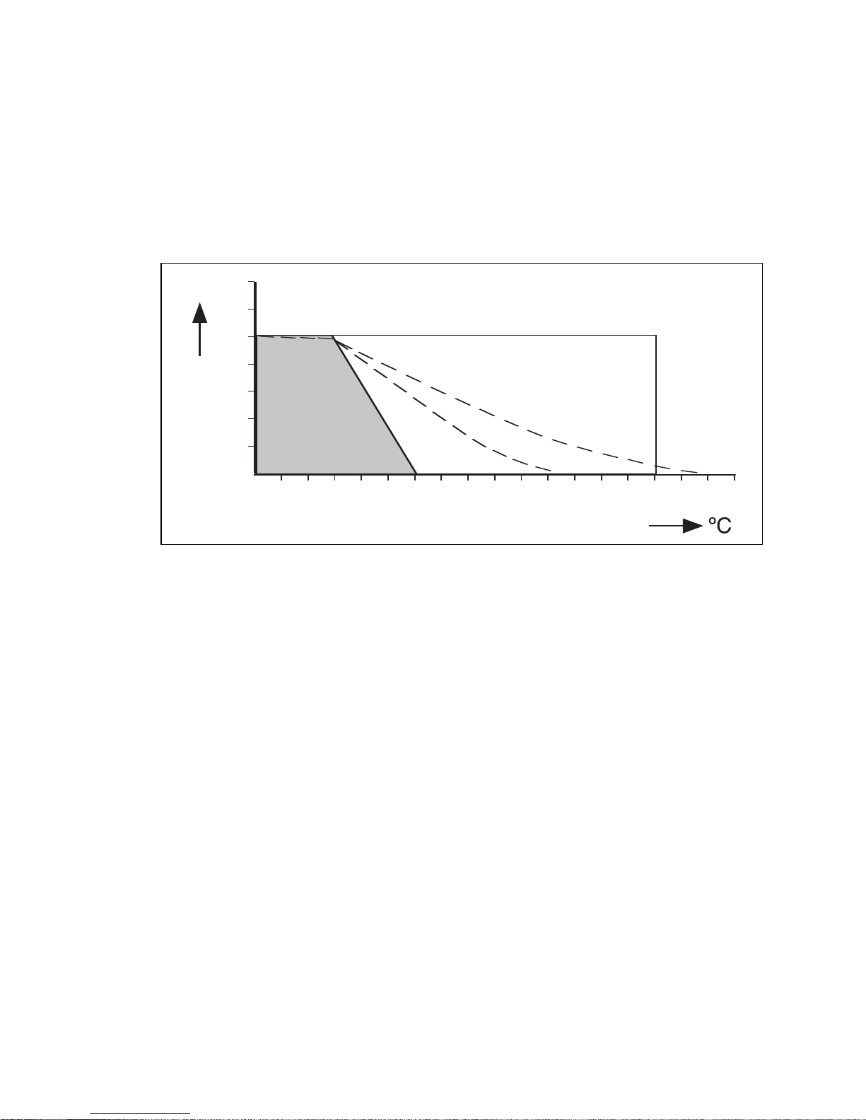
TEMPERATURE
- min -10 °C
- max depending on material and application (see fig. 2-2)
FLOW RATE (fittings only) : 0,1 to 10 1/min (depending on applicaiton)
PRESSURE
Figure 2-2. Pressure/temperature class
3
0 10 20 30 40 50 60 70 80 100 120 140 160
bar
2
4
6
8
10
12
AISI 316
PVDF
PP
PVC
Page 6
IM 12B6K1-01E-E
4
2-4. Model and codes
2-4-1. Fittings
Model Suffix Option Description
Code Code
FF20 Flow fitting
Material -P Polypropylene (PP)
-S
Stainless steel AISI 316 (SS)
-F Polyvinylidenefluoride (PVDF)
Number 22 For PH20
of holes 33 3 electrode mounting holes
43 4 electrode mounting holes
*B Style code B
Options /HCN2 FF20- .22
-Cleaning system /HCN3 FF20- .33
/HCN4
FF20- .43
Options /B For mounting Bellomatic reference electrodes
-Mounting kit
/D For mounting a combined electrode
of type SC21-AAC54.
/R For mounting (top) refillable electrodes
with long glass shaft.
-Flange adapters /FP1 DN15-PN10 PP
(NPT 1/2" male lap joint) /FP2
DN25-PN10 PP
/FP31/2" 150 lbs PP
/FP4 1" 150 lbs PP
/FF1 DN15-PN10 PVDF
/FF2 DN25-PN10 PVDF
/FF31/2" 150 lbs PVDF
/FF4
1" 150 lbs PVDF
/FS1 DN15-PN10 SS 316
/FS2 DN25-PN10 SS 316
/FS31/2" 150 lbs SS 316
/FS4 1" 150 lbs SS 316
-KCl-reservoir /K Electrolyte tubing (2.5 m) is included.
-Salt bridge /S For liquid which cannot stand contamination
with KCl.
-Certificate /MMaterial certificate 3.1B according to EN-10-204
(DIN 50-049) (on wetted par
Page 7
IM 12B6K1-01E-E
5
2-4-2. Subassemblies (flow fittings)
M
odel Suffix Option Description
Code Code
FS20 Subassembly (Flow fitting)
Material -V Polyvinylchloride (PVC)
-PPolypropylene (PP)
-SStainless steel AISI 316 (SS)
-F Polyvinylidenefluoride (PVDF)
Number 12
1 electrode mounting holes (only V,S)
of holes 22 For PH20
32 3 electrode mounting holes
43 4 electrode mounting holes (only V,S)
Mounting -WE W
elding end: Type, S12, S22,S32, S43
Glue for PVC: Type V12, V22, V32, V43
Heat welding: Type F22, F32, P22, P32
-TP Tapered pipe thread (2"NPT acc. ANSI B.20.1).
(for 2 and 3 holes version, and not in case of
type V22 and V32)
Options /HCN2 FS20- .22
-Cleaningsystem /HCN3
FS20- .32
/HCN4 FS20- .43
Options /B For mounting Bellomatic reference electrodes
-Mounting kit and combined electrodes.
/D For mounting a combined electrode of type
SC21-AAC54.
/R For mounting (top) refillable electr
odes
with long glass shaft.
-KCl-reservoir /K Electrolyte tubing (2.5 m) is included.
-Salt bridge /SFor liquid which cannot stand contamination
with KCl.
-Certificate /MMaterial certificate 3.1B according to EN-10-204
(DIN 50-049) (on wetted par
Page 8
IM 12B6K1-01E-E
6
5
5 (2.16")
3
6,5 (1.43")
1/2" NPT
Ø71 (2.80")
OUT
Ø8 (0.31")
1/2" NPT
Ø 90
(3.54")
6
0 (2.36")
IN
Ø 92
(3.62")
2
15 + 3 (8.46" + 0.12")
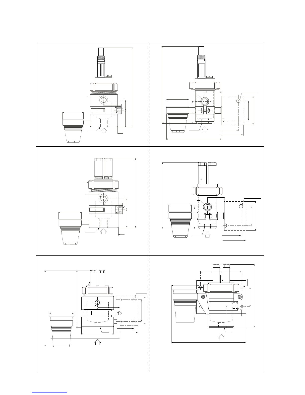
FF20-P33
FF20-F33
PP/PVDF
5
5 (2.16")
3
6,5 (1.43")
1/2" NPT
Ø71 (2.80")
OUT
Ø 8 (0,31")
1/2" NPT
Ø 90
(3.54")
60 (2.36")
IN
2
76 (10.82")
F
F20-P22
FF20-F22
PP/PVDF
1
20 (4.72")
Ø90 (3.54")
90 (3.54")
1/2"NPT
230 (9.05")
1/2"NPT
1
15 (4.52")
157 (0.18")
4XØ12 (0.47
")
OUT
IN
320 (12.6")
130 (5.11")
280 (11.02")
90 (3.54")
FF20-P43
FF20-F43
PP/PVDF
6
0 (2.36")
9
0 (3.54")
Ø70 (2.75")
5
0 (1.97")
1/2"NPT
67 (2.64")
1/2"NPT
100 (3.93")
1
30 (5.15")
3
XØ11 (0.43")
O
UT
I
N
205 (8.07")
FF20-S33
SS
190 (7.5")
6
0 (2.36")
9
0 (3.54")
5
0 (1.97")
1/2 "NPT
67 (2.64")
1/2"NPT
3XØ11 (0.43")
OUT
IN
255 (10.04")
=
=
Ø 71 ( 2.8 0")
13 0 (5.15")
1
00 ( 3.93 ")
FF20-S22
SS
Ø90 (3.54")
225 (8.86")
70 (2.75")
1/2"NPT
1/2"NPT
4XØ12 (0.47")
OUT
IN
150 (5.90")
265 (10.43")
80 (3.15")
DISTANCE WALL-OUTLET= 85 (3.35")
FF20-S43
Distance wall-outlet: 85 (3.35”)
SS
2-5. DIMENSIONS
2-5-1. Flow Fittings
Page 9

IM 12B6K1-01E-E
7
1
89(7,44")
81.5(3.21")
Ø
63 (2.48")
1
12 (4.41")
2
00(7.87")
112(4.41")
92(3.62")
2
-11.5 NPT
A
NSI
B.21.1
1
90(7.48")
2
-
11
,
5NPT
ANS
I
B.2
0
.1
1
12 (4.41")
8
2(3.23")
Ø
56 (2.20")
1
12 (4.41")
169 (6.65")
6
0 (2.36")
124(4.88")
1
24 (4.88")
105 (4.13")
Ø 56 (2.20")
53
(
2.08")
1
46 (5.75")
105 (4.13")
2-11,5 NPT
ANSI B.20.1
75
(
2.95")
1
38 (5.43")
105 (4.13")
2-11,5 NPT
ANSI B.20.1
70
(
2.75")
Ø 90 (3.54")
4
5 (1.77")
89 (3.50")
1
60
(
6.30")
1
05 (4.13")
Ø 88 (3.46")
1
29 (5.08")
58 (2.28")
1
06 (4.17")
FS20-V43-WE FS20-S43-WE
PVC SS
1
36 (5.35")
66
(
2.60")
Ø 63 (2.48")
2
6 (1.02")
FS20-S22-WE FS20-S22-TP
FS20-P22-TP
FS20-F22-TP
FS20-P22-WE
FS20-V22-WE
FS20-F22-WE
SS SS PP/PVDF PP/PVC/PVDF
FS20-S32-WE FS20-S32-TP
FS20-P32-TP
FS20-F32-TP
FS20-P32-WE
FS20-V32-WE
FS20-F32-WE
SS SS PP/PVDF PP/PVC/PVDF
2-5-1. Subassemblies
Page 10

IM 12B6K1-01E-E
8
3. PIPING AND INSTALLATION
3-1. General
It is important that, whatever method of mounting is used, the point of measurment is truly
representative of the entrie solution. Avoid an area where the measurement varies
significantly or the flow can be interrupted (the sensors must always be immersed in the
process liquid). The recommended type of fitting or subassembly will depend on pressure,
temperature, kind of liquid, pollution, etc. Check whether the specifications of the
fitting/subassembly and electrodes fulfil the maximum occuring process conditions. The
fitting/suassembly has several options and optional connection possibilities. Check that you
received the correct size and type.
3-2. Piping
3-2-1. Mounting in a sample line
Part of the process liquid is tapped off to
the flow fitting or subassembly (see fig. 3-1)
.
Figure 3-1
3-2-2. Mounting in a shunt line
By means of restrictor in the main line a small flow of the process liquid is lead through the
flow fitting or subassembly via the shunt line (see fig. 3-2). The pressure in the fitting or
subassembly is controlled by means of two valves.
Figure 3-2
PROCESS PIPING
P1
RESTRICTOR
P2
P2 < P1
12B6K1-41
MOUNTING IN A
SHUNT LINE
PROCESS PIPING
DRAIN
12B6K1-40
MOUNTING IN A
S
AMPLE LINE
Page 11

IM 12B6K1-01E-E
9
3-2-3. Mounting in a sample line with extra connection for buffer liquid/cleanser
The sample line has an extra input for cleaning or calibration (see fig. 3-3).
Figure 3-3
3-3. Installation
3-3-1. Mounting the fitting
Install the fitting at a convenient location for maintenance and calibration.
Ensure that there is some place at the top of the fitting (approx. 20 cm) for mounting or
replacing the electrodes.
Mounting the fitting in a piping system is shown in fig. 3-4.
Refer to §2-4 for dimensional drawings.
Figure 3-4 Figure 3-5
NOTE: The process connection (liquid outlet) can be turned from right to left.
1.
The plastic fittings have locking screws for the holder of the calibration dish
(see fig. 3-5). These screws must be loosened before turning.
2. The liquid outlet of the stainless steel fittings can be turned after loosening from the
mounting bracket (see exploded view at the end of this manual).
PROCESS PIPING
D
RAIN
buffer
liquid
cleaner
M
OUNTING IN A
S
AMPLE LINE
+CONNECT. FOR
B
UFFER...
12B6K1-44
MOUNTING THE FITTING
12B6K1-43
MOUNTING THE FITTING
Page 12

IM 12B6K1-01E-E
3-3-2. Mounting the subassembly
The subassembly can be cemented or welded directly in a piping system or in a T-piece of
it. Install the subassembly at a convenient location for maintenance and calibration.
Ensure that there is some place at the top of the fitting (approx. 20 cm) for mounting or
replacing electrodes.
Fig. 3-6 shows some mounting examples. Select the mounting position so that the sensors
are immersed in the process liquid during measurement.
(Model WU20) should be used (see fig. 3-7).
Figure 3-6
3-4. Sensor mounting
3-4-1. General
For stable measurement the glass- and the reference electrode should be mounted in the
holes nearest to the earth connection.
When mounting sensors of Yokogawa in a fitting or subassembly the electrode cables
(Model WU20) should be used (see fig. 3-7).
Figure 3-7
10 cm
colour
marker
screen
blue
core red
10 cm
colour
marker
colour
marker
outer
screening
white
core red
inner
screening
blue
Cable nut
Cable nut
colour
marker
COAX-cable (model WU20-PC) for single electrode
TRIAX-cable (model WU20-LT) for combined electrode
GLUE
GLUE
GLUE
10
Page 13

3-4-2. Mounting in a 1-hole design
Unscrew the electrode mounting set and fix
the cable and electrode as shown in fig. 3-8.
3-4-3. Mounting in a 3- and 4-hole
design
Unscrew the nut from the top end of the
fitting or subassembly. Fix the electrodes
and cables as shown in fig. 3-9.
Note: In the holes for placing the electrodes
are blanking plugs (stoppers). These
plugs can be placed in unused holes
after pushing the two O-rings over the
bottom end.
ATTENTION
To prevent fouling of the contact new
Yokogawa electrodes are delivered with a
cap. It is recommended to remove the cap
just before fixing the cable.
ENSURE THAT THERE IS NO MOISTURE
OR DUST IN THE PLUG
Figure 3-8 Figure 3-9
4. ACCESSORIES
4-1. General
For mounting the non-DIN sized sensors in
the fittings and subassemblies Yokogawa
added a range of accessories to the program
of fittings which can be indespensable tools
for optional measuring tools (the
specifications of the accessories are on
seperate sheets, see GS 12B6J1-E-E).
See the chapters below for mounting the
accessories.
4-2. Mounting kit for BELLOMATIC
electrodes (Model FP20-S13)
Using this mounting kit a BELLOMATIC
electrode of Yokogawa can be fixed in a
fitting or subassembly (see fig. 4-1).
This mounting kit can also be used for fixing
combined electrodes.
Figure 4-1
MOUNTING IN A 3- AND
4-HOLE DESIGN
12B6K1-23
MOUNTING KIT BELLOMATIC
RING (K1500HC)
RING (K1500HC)
ELECTRODE
"O"-RINGS
(11 X 3)
K1500BZ
IM 12B6K1-E-E
11
Page 14

IM 12B6K1-01E-E
RECOMMENDED ELECTRODES1)
TYPE DESCRIPTION
SR20-AC32 Reference electrode
SC21-AAC54
2
) Combined pH/ref. electrode
SC29-PTC54
2
) Combined redox/ref. electrode
1
) For specifications of the electrodes see GS 12B6J1
2
) Atmospheric conditions only
PARTS AND ACCESSORIES
ORDER NR. DESCRIPTION
K1500HC Set rubber ring (10x)
K1500GE Set O-rings (5x) for BELLOMATIC electrode
K1500GF
250 ml KCI-solution (1 m.)
K1520VA
250 ml KCI-solution (3,3 m.)
K1500GG
250 ml KCI-solution (1 m.) thickend
K1520VN
250 ml KCI-solution, (3,3 m.) thickend
4-3. Mounting kit for sterilisable
applications (Model FP20-S14)
To assure sterilisable applications and a
constant flow of electrolyte this mounting kit
can be used for fixing combined electrodes
with a large KCI-reservoir (see fig. 4-2).
For pressurising the system there is a 1/8”
nipple for connecting to each standard
pump. The pressure inside the holder may
never exceed the specifications of the
electrodes. See GS 12B6J1 for these
specifications.
ELECTRODES TO BE USED1)
TYPE DESCRIPTION
SC21-AAC54 Combined pH/ref.
electrode
SC29-PTC54 Combined redox/ref.
electrode
1
) For specifications see general specifications
sheet GS 12B6J1.
PARTS AND ACCESSORIES
ORDER NR.
DESCRIPTION
K1500GS Set O-rings
K1520VN
250 ml KCI-solution,
(3,3 m.) thickend
Figure 4-2
12B6K1-24
MOUNTING KIT FOR ST
APPLICATIONS
TAPE
ELECTRODE
"O"-RINGS (11x3)
(K1500BZ)
"O"-RINGS
(K1500GS)
12
Page 15

IM 12B6K1-01E-E
4-4. Mounting kit for refillable ref.
electrodes
This mounting kit replaces the standard
electrode mouting set so that elctrodes of
Yokogawa with a long glass shaft can be
fixed in the fitting or subassembly (see fig. 4-
3). This mounting kit may be used as process
pressure up to 3 bar. Higher pressure ratings
require the standard mounting set for
electrodes with DIN dimensions or, alternately
a salt bridge (see §4-5). The refillable
electrodes can be connected to a KCIreservoir via a silicone tubing (see fig. 4-3).
The pressure on the KCI-solution and
consequently, the liquid outlet can be
increased by mounting the reservoir above
the fitting or subassembly. This prevents
penetration of the process liquid into the
electrode.
Note: The pressure on the KCI-solution must
exceed the liquid pressure. Figure 4-3
In §7 you will find the spareparts
4-5. Cleaning systems
4-5-1. General
The standardised design of the fittings and subassemblies makes it possible to mount
cleaning systems directly. The 4-hole types are especially designed for these applications.
Three different types of cleaning systems are available (see fig. 4-4):
- mechanical cleaning (electrically or mechanically driven)
- chemical cleaning
- ultra sonic cleaning
Detailed specifications of the cleaning systems are on seperate sheets (see GS 12B6V1).
K
CI-RESERVOIR
(K1500FU)
S
ILICONE TUBING
(K1500GA)
"O"-RINGS
(11 x 3)
Figure 4-4
brush cleaning
chemical cleaning
13
Page 16

IM 12B6K1-01E-E
14
4-5-3. Mechanical cleaning
The brush of this cleaning system periodically strikes along the sensitive glass membrane of
the electrode, so that this part is wiped frequently preventing sediment formation on it.
Electrically or pneumatically versions are available.
Electrically driven brush cleaning (Model FC20-VE). Figure 4-5 shows the mounting.
PARTS AND ACCESSORIES
ORDER NR. DESCRIPTION
WU20-PC Cable (to be used as a
supply cable for the motor)
BC10 Supply unit for the motor
K1520NG Brush holder
K1520NB Brush
K1520NF Motor unit
Figure 4-5
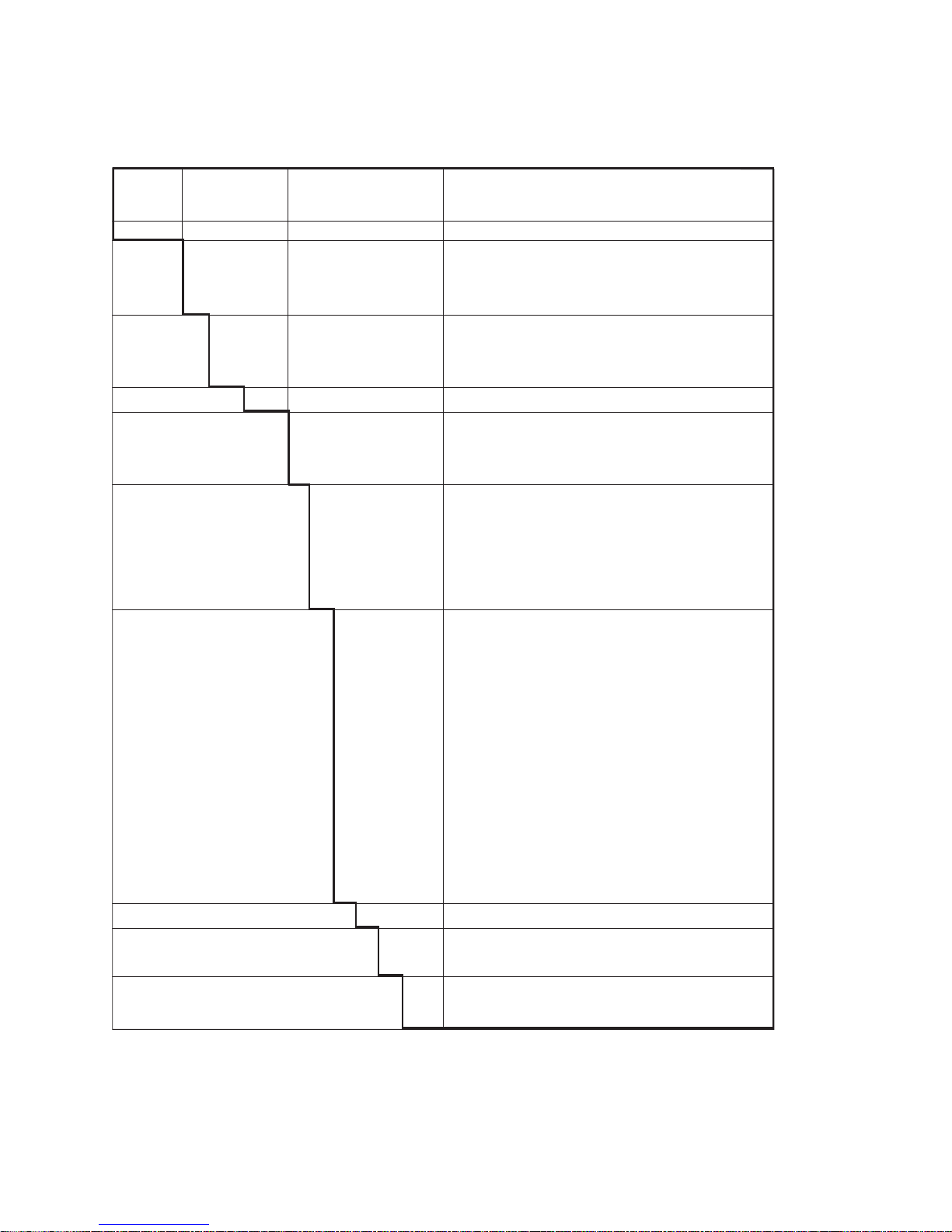
4-5-2. Selection criteria
cleaning system mechanical chemical acoustical
brush acid base emulsifier ultra sonic
Applications:
oils fats x x
resins (wood, pulp) x x
emulsions of latex x
fibers (paper, textile) x
crystalline precipations
(carbonates) x xx x
amorpheus precipations x xx x
BRUSH HOLDER
MOTOR
SUPPLY
TYPE BC10
CABLE
WU20
O-RING (11x 3)
12B6K1-26
MECHANICAL CLEANING
Page 17

15
Pneumatically driven brush cleaning
(Model FC20-VP)
PARTS AND ACCESSORIES
ORDER NR. DESCRIPTION
K1520NA Tubing (x4 mm)
K1520NG Brush holder
K1520NB Brush
K1520NG Protection hose
K1520NH Piston
K1520NJ Control unit
Figure 4-6
4-5-4. Chemical cleaning HCN.
The chemical cleaning system is effective in
processes where deposits can be removed
by a suitable solvent. Good cleaning effects
can be obtained from periodically spraying of
an electrode. EXA PH402 has a built-in wash
timer with programmable washtime, interval
time and relaxation time for automatic
cleaning of the electrodes, preventing
pollution of the pH sensitive parts. After
washing, it is possible to check the response
time of the electrodes. A built-in (no return)
nozzle in the spray unit prevents penetration
of the process liquid in the cleaning system.
The standardised dimensions allow mounting
in all flow-, insertion- and immersion fittings
of Yokogawa as well as back-end mounting
on the 4-in-one pH/Redox electrodes.
Features
• The EXA pH402 analyzer has a built-in
timer and HOLD circuit.
• Built-in (no return) nozzle to prevent
penetration of the process liquid into the
cleaning system.
Figure 4-7
PISTON
CONTROL
UNIT
TUBING
K1520NA
O-RING (11x 3)
B
RUSH HOLDER
PROTECTION
HOSE
K1520NC
K1547PP
(spare tubing, EPDM)
O-rings
(11x3)
IM 12B6K1-01E-E
Page 18

IM 12B6K1-01E-E
16
Specifications
Materials
Nozzle : Hastelloy
O-rings : EPDM rubber
Mounting set : Stainless steel
Tubing : 1/4” (OD Ø) Nylon tubing
Process cond. : Max. 1 MPa (10 bar) at 100 ºC
Mounting
K1547PA : /HCN2, 2-hole flow-, insertion fitting (PH20)
K1547PA : /HCN3, 3-hole flow-, insertion-, immersion fitting
K1547PB : /HCN4, 4-hole flow-, insertion-, immersion fitting
K1547PJ : /HCNF, back-end mounting on FU20/PH20
4-5. Salt bridge
(Model SB20-VP, VC and VS)
This reference electrode/salt bridge
combination allows pH and ORP(Redox)
measurement with the normal electrodes in
those cases when:
a. excessive contamination of the ceramic
flow diaphragm is expected
- the flow of the reference liquid through
the diaphragm is increased by
pressurising the container.
Consequently, the contamination rate will
decrease.
b. the process to be measured cannot stand
the contamination with KCl
- the salt bridge can be filled with several
electrolytes.
c. measurements have to be performed at
pressures up to 10 bar and temperatures
up to 100 °C
- the container with reference liquid can
be pressurised.
FLOW TUBE (A)
Material : glass
Flow diaphragm : ceramic, PTFE or sleeve
Connector : Ryton R4
TUBING (B)
Material : nylon
Diameter
: 1/4” o.d.
Length : 2 mtr.
CONTAINER (C)
Container : PVC, PVC (transparent)
Electrode
mounting set : Ryton R4
“O” ring : silicone
REFERENCE
ELECTRODE
12B6K1-30
S
ALT BRIDGE
B
C
Ø 75
65
166
Ø 75
Ø 6.5
A
Ø 17
Ø 12
120
39
Figure 4-8
Figure 4-9
Page 19

IM 12B6K1-01E-E
17
5. MAINTENANCE
5-1 General
Before the electrodes can be serviced, the electrode holder should be physically separated
from the process. The fittings can be changed from the measuring position in the
maintenance position by following the reversed procedures described in §4.
5-2. Cleaning
Cleaning the fitting
When process liquid contains slurry which intends to settle in the fitting regularly, the
electrode holder must be removed for cleaning.
Cleaning the electrodes
When the sensitivity of the electrode has decreased or the response has slowed down, the
electrode should be cleaned. The 3- and 4-hole fittings are provided with a calibration ring
with a set of beakers. The electrode holder complete with electrodes and liquid earth
sensor can be placed on the ring for cleaning.
If cleaning with hot water is not sufficient, more aggressive water based agents should be
used.
-
Deposits of limes, hydroxides or carbonates can be removed by immersing the electrode
in a solution containing diluted hydrochloric acid. Afterwards rinse the electrode with
water.
- Deposits of oil and fat can be removed with hot water in conjunction with a detergent.
When the results are unsatisfactory a mild (carbonate based) abrasive can be used.
- Protein (albuminous) deposits should be removed with a protein enzymatic solution. For
instance a solution containing 8.5 ml concentrated hydrochloric acid and 10 gr pepsin in 1
litre water.
Connection : nylon
Weight : approx. 300 g.
Mounting : wall mounting (support with hole for screw M5)
Temperature/
pressure ratio : max. 200 kPa (2 bar) at 100°C
Notes:
1. The dimensions of the flow tube equal to those of standard electrodes
2. The standard reference electrodes can be mounted in the container
3. To observe the electrolyte level, the container is made of PVC.
For mounting instructions see fig. 4-9
PARTS AND ACCESSORIES
ORDER NR. DESCRIPTION
K1500BW Flow tube with ceramic diaphragm
K1500EE Flow tube with PTFE diaphragm
K1500EF Flow tube with sleeve diaphragm
K1520VA Electrolyte 3.3M KCl (250 ml)
K1520VN Thickened electrolyte 3.3M KCl (250 ml)
K1500GF Electrolyte 1M KCl (250 ml)
K1500GG Thickened electrolyte 1M KCl (250 ml)
Page 20

IM 12B6K1-01E-E
18
ATTENTION
Avoid using non-polar solvents like tri-chloro ethylene, toluene or hexane. Even cleaning
with ethanol or acetone is not recommended. These solvents will break up the gel-layer on
the glass bulb and afterwards needs to remain soaked in water for at least 12 hours before
functioning normal. The PTFE diaphragm of the combined electrode can sometimes be
regenerated by putting it in hot (60 to 80 °C) 1 molar Potassium chloride (KCl) solution and
letting it cool to room temperature. After cleaning the probe is re-inserted into the process
by following the reverse procedure (see §3-5).
5-3. Calibration
It is recommended to start calibration with clean electrodes. Always calibrate new
electrodes. With the electrodes connected to the transmitter a calibration can take place.
Check the appropriate chapters in the instruction manual of the pH transmitter for details.
General procedure for calibration
To calibrate a pH transmitter two buffer solutions with known pH value are required. It is
recommended that one buffer solution has a value near pH 7.
Depending on the liquid to be measured the second buffer solution should either be in the
acidic or base area. Normally the buffers pH 4.01 or 9.22 are used.
Generally the procedure for calibration is as follows:
- Clean the electrodes
- Rinse the electrodes
- Immerse the electrodes in the first buffer solution (pH 7)
- Adjust the asymmetry setting of the transmitter for reading a known value
- Rinse the electrodes
- Immerse the electrodes in the second buffer (pH 4 or pH 9)
- Adjust the slope setting of the transmitter for reading a known value
- Rinse the electrodes.
During calibration the temperature compensation should be active. It is advised top
calibrate with buffer solutions at a temperature near the process temperature.
5-4. Replacing the O-rings
The exploded view (see §6) shows the position of the sealing O-rings. The O-rings used in
the wetted part are made of silicone rubber, which has superior resistance to corrosion
suitable for use with most process liquids.
Usually no periodical inspection is necessary. To prevent trouble, replace the O-ring seal
periodically, e.g. every year.
Page 21

IM 12B6K1-01E-E
19
6. EXPLODED VIEW
ASSEMBLED FLOW
FF20-.33
12B6K1-32
ASSEMBLED FLOW
FF20-.43
12B6K1-33
ASSEMBLED FLOW
FF20-S33
12B6K1-34
ASSEMBLED FLOW
FF20-S43
FF20- S33
FF20
- S43
F
F20- . 43
F
F20- S22
F
F20- . 33
F
F20- P22
FF20- F22
Page 22

IM 12B6K1-01E-E
20
1
2B6K1-35
S
UBASSY FLOW
FS20-.33
1
2B6K1-36
SUBASSY FLOW
FS20-.43
12B6K1-37
SUBASSY
FS20-S33
12B6K1-38
SUBASSY FLOW
FS20-S43
F
S20- . 12
FS20- S32
FS20- S43
FS20- . 43FS20- . 32
FS20- S22
FS20- P22
FS20- F22
FS20- V22
Page 23

21
SPARE PARTS
Accesoires
Part no. Description
K1500FU KCl reservoir PVC for F*20
SB20 Salt bridge
K1500BX Grommet for watertight cable input in PG 16 gland
(3 electrodes cables and liquid earth cable)
K1500BY Mounting kit for (top) refillable electrodes
K1547PA Complete hastelloy cleaning system /HCN2 and /HCN3
K1547PB Complete hastelloy cleaning system /HCN4
K1521AD Flange adapter /FS3
K1521AE Flange adapter /FF3
K1521AF Flange adapter /FP3
K1521AG Flange adapter /FS4
K1521AH Flange adapter /FF4
K1521AJ Flange adapter /FP4
K1521AK Flange adapter /FS1
K1521AL Flange adapter /FF1
K1521AM Flange adapter /FP1
K1521AN Flange adapter /FS2
K1521AP Flange adapter /FF2
K1521AQ Flange adapter /FP2
Consumable Parts
Part no. Description
6C231 Buffer powder pH 1.68 (at 25 ºC)
6C232 Buffer powder pH 4.01 (at 25 ºC)
6C234 Buffer powder pH 6.98 (at 25 ºC)
6C237 Buffer powder pH 6.87 (at 25 ºC)
6C236 Buffer powder pH 9.18 (at 25 ºC)
K1500GF 250 ml. KCl-solution (1 M)
K1520VA 250 ml. KCl-solution (3.3 M)
K1500GG 250 ml. KCl-solution (1 M), thickened
K1520VN 250 ml. KCl-solution (3.3 M), thickened
Cables
Part no. Description
K1500FV Liquid earth cable (10 m)
K1500DU Liquid earth cable (25 m)
WU20-PC02 COAX-cable (2 m) for single electrode
WU20-PC05 COAX-cable (5.5 m) for single electrode
WU20-PC10 COAX-cable (10 m) for single electrode
WU20-PC15 COAX-cable (15 m) for single electrode
WU20-PC20 COAX-cable (20 m) for single electrode
WU20-PC25 COAX-cable (25 m) for single electrode
WU20-LT02 TRIAX-cable (2 m) for combined electrode
WU20-LT05 TRIAX-cable (5.5 m) for combined electrode
WU20-LT10 TRIAX-cable (10 m) for combined electrode
WU20-LT15
TRIAX-cable (15 m) for combined electrode
WU20-LT20 TRIAX-cable (20 m) for combined electrode
WU20-LT25 TRIAX-cable (25 m) for combined electrode
IM 12B6K1-E-E
Page 24

IM 12B6K1-01E-E
Spare parts FF20
Part no. Description
K1500AN Hauling parts kit for FD20-SS
K1500AP Hauling parts kit for FD20-plastic
K1500BV O-rings EPDM 11x3 (6 Pcs.)
K1500BW Flow tube for SB20-VC
K1500BY Option /R for F*20.. (82850747)
K1500BZ O-rings Viton 11x3 (6Pcs)51250
K1500DU Liquid earth cable 25m
K1500DW Set of 12 cable nuts for WU20
K1500DX 5 m tubing for SB20
K1500DZ Nut SS, FF/S20-3* + ISC40FF/S
K1500EK O-rings viton 6.07x1.78 (5x2)
K1500EL Mounting set for FF20-S22/33
K1500EQ O-ring set EPDM FF20-S22
K1500ER O-ring set Viton FF20-S22
K1500ES O-ring set EPDM FF20P&F33
K1500ET O-ring set Viton FF20P&F33
K1500EU O-ring set EPDM FF20-S33
K1500EV O-ring set Viton FF20-S33
K1500EW O-ring set EPDM FF20P&F43
K1500EX O-ring set Viton FF20P&F43
K1500EY O-ring set EPDM FF20-S43
K1500EZ O-ring set Viton FF20-S43
K1500FK O-ring set Viton FF20P&F22
K1500FL O-ring set standard FF20P&F22
K1500FM O-ring set FF20-S22
K1500FU KCl reservoir PVC for F*20
K1500FV Liquid earth cable 10m
K1500GA 5 m tube for KCl reservoir
K1500GN O-ring set FF/FS20 3-hole SS
K1500GP O-ring set FF/FS20 3-hole P/F
K1500GR O-rings silicon 11x3 8pcs
K1500GT O-ring set silicon. FF20-.4.
K1500GZ Earthpin assy for F*20 non-S
K1500HA Calibr. dish for FF20-*33 (50)
K1500HB Calibr. dish for FF20-*43 (50)
K1500HD O-rings silicon 11x3 50pcs
K1500ZA Nut PVDF for old FF20-F33
K1500ZB Nut PP for old FF20-P33
K1511DP O-rings viton 21.9x2.62 (5x2)
K1520CE Spare 3-hole holder PP
K1520CF Spare 3-hole holder PVDF
K1521AD Flange adapter /FS3
K1521AE Flange adapter /FF3
K1521AF Flange adapter /FP3
K1521AG Flange adapter /FS4
K1521AH Flange adapter /FF4
K1521AJ Flange adapter /FP4
K1521AK
Flange adapter /FS1
K1521AL Flange adapter /FF1
22
Page 25

IM 12B6K1-01E-E
23
K1521AM Flange adapter /FP1
K1521AN Flange adapter /FS2
K1521AP Flange adapter /FF2
K1521AQ Flange adapter /FP2
K1530UL Tubing for FD30/JC, 10 metre
K1547PA Hast. cleaning unit HCN2/3
K1547PB Hast. cleaning unit HCN4
K1547PF Nozzle and mounting HCN2/3/F
K1547PG Nozzle and mounting HCN4
K1547PH 10 m Nylon Tube and mounting
K1547PP Spare Part EPDM spraying valves
Spare parts FS20
Part no. Description
K1500BV O-rings EPDM 11x3 (6 Pcs.)
K1500BW Flow tube for SB20-VC
K1500BY Option /R for F*20.. (82850747)
K1500DU Liquid earth cable 25m
K1500DW Set of 12 cable nuts for WU20
K1500DX 5 m tubing for SB20
K1500DZ Nut SS, FF/S20-3* + ISC40FF/S
K1500EK O-rings viton 6.07x1.78 (5x2)
K1500ER O-ring set Viton FF20-S22
K1500FU KCl reservoir PVC for F*20
K1500FV Liquid earth cable 10m
K1500GA 5 m tube for KCl reservoir
K1500GN O-ring set FF/FS20 3-hole SS
K1500GP O-ring set FF/FS20 3-hole P/F
K1500GR O-rings silicon 11x3 8pcs
K1500GT O-ring set silicon. FF20-.4.
K1500GZ Earthpin assy for F*20 non-S
K1500HD O-rings silicon 11x3 50pcs
K1511DP O-rings viton 21.9x2.62 (5x2)
K1520CD Spare 3-hole holder PVC
K1520CE Spare 3-hole holder PP
K1520CF Spare 3-hole holder PVDF
K1530UL Tubing for FD30/JC, 10 metre
K1547PA Hast. cleaning unit HCN2/3
K1547PB Hast. cleaning unit HCN4
K1547PF Nozzle and mounting HCN2/3/F
K1547PG Nozzle and mounting HCN4
K1547PH 10 m Nylon Tube and mounting
K1547PP Spare Part EPDM spraying valves
Page 26

IM 12D7J4-E-H
Subject to change without notice Printed in The Netherlands, 06-507 (A) Q
Copyright ©
YOKOGAWA EUROPE B.V.
Databankweg 20
3821 AL Amersfoort
The Netherlands
Tel. +31-33-4641 611
Fax +31-33-4641 610
E-mail: info@nl.yokogawa.com
www.yokogawa.com/eu
YOKOGAWA CORPORATION OF AMERICA
2 Dart Road
Newnan GA 30265
United States
Tel. (1)-770-253-7000
Fax (1)-770-251-2088
E-mail: info@yca.com
www.yokogawa.com/us
YOKOGAWA ELECTRIC ASIA Pte. Ltd.
5 Bedok South Road
Singapore 469270
Singapore
Tel. (65)-241-9933
Fax (65)-241-2606
E-mail: webinfo@yas.com.sg
www.yokogawa.com.sg
YOKOGAWA HEADQUARTERS
9-32, Nakacho 2-chome,
Musashinoshi
Tokyo 180
Japan
Tel. (81)-422-52-5535
Fax (81)-422-55-1202
E-mail: webinfo@mls.yokogawa.co.jp
www.yokogawa.com
Yokogawa has an
extensive sales and
distribution network.
Please refer to the
European website
(www.yokogawa.com/eu)
to contact your nearest
representative.
IM 12B6K1-01E-E
 Loading...