

Page 1
Instruction
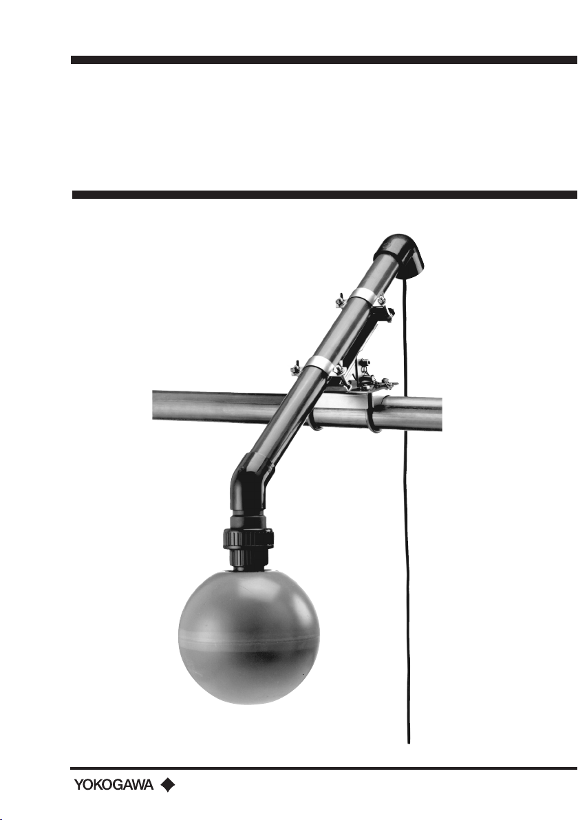
Models FD30 / PB30
Manual
Fittings for the DO30G
IM 12J6K4-E-E
5th edition
Page 2

2
3
Table of contents
1. Introduction ..............................................................................................................3
2. Unpacking and checking ........................................................................................3
3. Warranty and service ...............................................................................................3
4. Genral specifications ...............................................................................................4
4-1. Model FD30 Immersion Fitting .............................................................................4
4.2 Model PB30 Floating Ball Fitting ..........................................................................5
5 Installation ................................................................................................................6
5.1 General................................................................................................................6
5.2 Assembling and mounting of the immersion fitting...............................................6
5.2.1 Checklist ..................................................................................................6
5.2.2 Preparing the immersion fitting .................................................................7
5.2.3 Mounting the sensor in the immersion fitting ............................................7
5.2.4 Mounting the sensor cleaner (/JC option) .................................................7
5.3 Installing the floating ball fitting ............................................................................8
5.3.1 Checklist ..................................................................................................8
5.3.2 Installation ................................................................................................8
5.3.3 Assembling the floating ball fitting (ref to Figure 4)....................................8
6 Spare parts ...............................................................................................................9
6.1 Model FD30V27 Immersion Fitting .......................................................................9
6.2 Sensor Cleaner (/JC option) ................................................................................9
6.3 Model PB30 Floating Ball Fitting ..........................................................................9
7 Dimensions .............................................................................................................10
1. Introduction
To support the Yokogawa Model DO30G sensor for measuring dissolved Oxygen, two types
of sensor holders are offered; an immersion fitting (Model FD30V27) and a floating ball fitting
(Model PB30). Both fittings are intended for mounting the DO30G in a tank, measuring
either on the surface or sub-surface of the process liquid.
The type of sensor holder, as well as the point of installation, should be selected to allow
measurement in a location where the measurement truly represents the entire solution.
Avoid areas where the measurement value varies significantly e.g. stagnant corners. Select a
place where the sensor is always immersed in the process liquid.
Properties of the sensor holders are:
Model FD30V70
• Sub-surface measurement of dissolved Oxygen
• Available in different pipe-lengths – i.e. 40mm outer diameter
• Available with a metric to inch adapter – i.e. 40 to 42mm outer diameter (standard 1¼“
pipe)
• Standard equipped with membrane check-facility
• Available in flanged and non-flanged version
• Optional Jet Cleaning (/JC Option) for avoiding fouling of the membrane
• Optional Mounting Set (/MS1 Option) for convenient mounting)
Model PB30
• Designed for minimal user maintenance
• Good flow of sample at the membrane due to wave action and constant ball movement
• Constant measurement depth
• Standard equipped with membrane check-facility
• Shipped including a winch mounting mechanism
IM 12J6K4-E-E
2. Unpacking and checking
Upon receipt of the goods, carefully inspect the shipping package for any evidence of
damage. If the carton is damaged, notify the shipping agent and the sales organizationv
immediately.
If the shipping package is not damaged, remove the products and parts. Confirm that
all items shown on the packing list are available and that the package does not contain
any parts or accessories hidden between the shock absorbing fillers. Notify the sales
organization if items are missing.
3. Warranty and service
Products and parts are warranted to be free from defects in workmanship and material
under normal use and service for a period of typically twelve months from the date of
shipment by manufacturer. The sales organization has the possibility to deviate from this
typical warranty period and the actual terms and conditions as specified in the sales order
must be consulted. Damage caused by wear and tear, inadequate maintenance, corrosion
and attack by chemical processes are excluded from this warranty coverage.
IM 12J6K4-E-E
Page 3
4
5
All defective goods need to be sent to the service of the sales organization for repair or
replacement and the returned material should be accompanied by a letter of transmittal,
which should include the following information:
• Part number, Model code and Serial number
• Date and number of sales order
• Length of time of service and type of service
• Description of the faulty operation of the device and the circumstances of the failure
• Pressure, temperature, process composition and all other process conditions or
environmental circumstances which are related to the installation and possibly failure of the
device
• Statement as to whether warranty or non-warranty service is requested
• Complete shipping and billing instructions for return of material and name, phone number
of contact person that can be approached for further information.
The returned goods that have been in contact with process fluids must be detoxified and
disinfected prior to shipment for the health and safety of our employees. Material Safety
Data sheets must be included for all components of the processes in which the sensors/
fittings have been used. The shipping address where to the goods have to be returned is
specified on the original sales order or on the back page of this manual.
4. General specifications
4.1 Model FD30 Immersion Fitting
Wetted materials
- Body & flange : Polyvinylchloride (PVC)
- O-rings : Silicone rubber
- Blanking plug : Ryton R4 (remove before use!)
- Conductive bushing : Brass
Temperature
- Minimum : -10 °C
- Maximum : +50 °C
Pressure : 2 bar max.
Immersion length : 0.5 to 2.0 m (10 cm steps) When ordered as a
subassembly (pipe length 00), a tube with PVC
cement will be delivered with the holder
Weight
- Without flange : 1.35 kg + 0.2 kg per 0.5 meter
- With flange : 0.5 kg extra
Options
- Sensor/cable : See DO30G
- Flexible conduit : PVC and Nylon
Option /PH5 : 5 meter protection hose
Option /PH10 : 10 meter protection hose
- Jet cleaner (Option /JC) : Materials: PVC, Nylon, PVDF and PTFE
Temperature: as FD30
Pressure: as FD30
Immersion length: nominal + 4 cm
- Mounting set (Option /MS1) : Material; Galvanized steel
Model and Suffix code
Immersion Fitting
Model Suffix Option Description
FD30V27 Immersion Fitting PVC
Immersion -00 Pipe supplied by user
length -xx Between 0.5 and 2.0
(in steps of 0.1m) Example: 06 = 0.6 m
Mounting -FN No flange
flange -F1 DIN DN50 PN10
-F2 ANSI 2” 150 lbs
*A Style A
Protection hose /PH5 5 meter
/PH10 10 mtr
Jet Cleaner /JC *
Mounting set /MS1 *
* Not available with flanged versions.
4.2 Model PB30 Floating Ball Fitting
Wetted materials : High impact polystyrene, PVC & Brass
Temperature : 0-40 °C
Mounting bracket : Galvanized steel, for rail, or surface mounting
Sensor/cable : See DO30G
Shipping details
- Weight : 12.5 kg Approx.
- Package size : 490 x 320 x 340 mm
- Main support arm : 2.5 m
Model and Suffix Codes
Floating Ball
Model Suffix Code Description
PB30 Floating Ball Fitting
Pipe length -00 Pipe supplied by user
-25 2.5 meter
Sensor type -SNN No sensor
Cable length -00 No cable
IM 12J6K4-E-E
IM 12J6K4-E-E
Page 4

6
7
5. Installation
5.1 General
It is important to have the point of measurement in a location that is representing the
process composition. Check whether the specifications of the sensor/fitting/holder fulfill
the maximum occurring process conditions. Install the fitting in a place where it can be
maintained and calibrated safely and easily. After installation of the sensor it may need
several hours to stabilize readings. Stabilization can take up to 24 hours.
ATTENTION
Do not insert the fitting/holder into the process without the sensor mounted, to
avoid the cable leads becoming wet.
5.2 Assembling and mounting of the immersion fitting
5.2.1 Checklist
The FD30V27-xx-FN fittings will be delivered completely assembled. Flanges (suffix code -F1
or -F2) and options will be delivered separately. The FD30V27-00 version will be delivered in
parts excluding the pipe (see Figure 1). The holder piece (3) and the top piece (1a/b) have
an internal diameter suitable for both 40 mm and 11/4" customer's pipe. The jet cleaning
(option /JC) will be delivered as indicated in Figure 2.
2
11
1a
10
3
6
7
Top piece (1a/b)
• Pigtail (2)
Holder piece (3)
1b
• Screw piece (4)
5
• Conductive bu shing (5)
• “O”-ring (6)
• Stopper (7)
8
• “O”-ring (8)
Tube PVC adhesive (9)
4
Instruction manual (10)
Flange (if specified) (11)
9
Figure 2
5.2.2 Preparing the immersion fitting
Prepare the immersion fitting by unscrewing
the screw piece (4) from the bottom of the
fitting. Remove the stopper (7), which can
be discarded, and the conductive bushing
(5). The screw piece will be used to fix the
DO sensor in the fitting. When a flexible
conduit (protecting hose) will be used,
the pigtail part (2) can also be discarded.
When an immersion fitting with cleaner
is used the cleaning cage will be used to
fix the DO-sensor. In that case the screw
piece can also be discarded. In case of
a FD30V27-00 version the top piece and
the holder piece should be mounted on
the customers pipe using the supplied
adhesive. Ensure that the sealing will be
watertight.
5.2.3 Mounting the sensor in the
immersion fitting
Pull the sensor cable through the O-ring
into the fitting and through the pigtail (see
Figure 3). In case a flexible conduit will
be used please remove the pigtail and
follow the instructions delivered with the
protecting hose option. Push the O-ring
over the cable assembly until it lies on the
knurled ring. Plug the cable assembly into
the sensor body, if this was not performed
before. Secure the cable assembly with the
knurled ring. Place the sensor in the fitting
and put the bushing (essential for sensor
diagnostics) around the sensor as far as
it will go. Then screw the screw piece, or
the cleaning cage, in again. This will fix the
sensor in place by compressing the O-ring.
Tighten the pigtail at the top of the fitting.
Figure 1
IM 12J6K4-E-E
IM 12J6K4-E-E
Page 5

8
9
5.2.4 Mounting the sensor cleaner (/JC
option)
• After fixing the sensor with the cleaning
cage it is possible to screw the cleaner
tubing on the cage using the swage
lock coupling material provided with the
cleaner.
• It is recommended to fix the tubing to the
holder using tie wraps.
• Keep some flexible length of tubing for
ease of maintenance.
The cleaner can be used for both water and
air. It is recommended to use a solenoid
valve of the normally closed type with
matching connections. The solenoid valve
can be switched with the wash contact of
the EXA DO-converter.
5.3 Installing the floating ball fitting
5.3.1 Checklist
The floating ball fitting with sensor for
Dissolved Oxygen will be delivered in parts
and has to be assembled before it can
be used. Check if all standard parts are
delivered, see Figure 4. Please note that
items (4), (5) and (2 + 6) are optional and, if
not specified with the order, these parts will
not be delivered. The position ring (9) will
only be received when PB30-00. is ordered.
This part is only needed when 11/2" pipe
will be used in stead of 50 mm.
Figure 3
5.3.2 Installation
Mount the floating ball not exactly vertical, but under a slight angle, so that air bubbles do
not 'stick' or adhere to the membrane.
5.3.3 Assembling the floating ball fitting (ref to Figure 4)
• Attach the mounting bracket (1) to wall or pipe; clamps are already fixed to the bracket.
• Install the main support arm (2) (in case of PB30-00... the customers pipe), in the
mounting bracket (1) and adjust its length to the desired length.
• Use the supplied adhesive (7) to stick the lower support to the main support arm (2).
When a 11/2" pipe is used, the position ring (10) must be mounted in between them to
compensate for the difference.
• Attach (not for PB30-00...) the 90° elbow (6) to the upper end of the main support arm
and cement it with adhesive (7).
• Guide the cable assembly (4) through the main support arm.
• Position the complete sensor (4+5) in the lower support.
• Place the lower support (3) into the ball (8) by screwing the fixing nut hand-tight.
• Connect the leads of the cable to the EXA DO converter.
6
7
2
1
9
3
10
4
7
8
Figure 4
6. Spare parts
6.1 Model FD30V27 Immersion Fitting
Item Description Spare part no
6 5 x O-ring K1500FX
8 5 x O-ring K1500FY
6.2 Sensor Cleaner (/JC option)
Item Description Spare part no
1 5 x O-ring 37.7 X 2.6 for mounting sensor in fitting K1500FY
2 Holder
3+4 Nozzle parts K1500AZ
7 10m tubing (1/4 “) for jet cleaner K1530UL
3,4,6 Spray nozzle for jet cleaner K1530UK
6.3 Model PB30 Floating Ball Fitting
Item Description Spare part no
1 Mounting bracket K1530DQ
2 Main support arm
3 Lower support arm with O-ring K1530QA
4 DO30G sensor See DO30G
6 Elbow 90º
7 Tube PVC adhesive
8 Floating ball assembly with O-ring K1530SA
9 Position ring
10 O-ring 25.3 x 3.2 Viton 70º shore K1500AV (5x)
IM 12J6K4-E-E
IM 12J6K4-E-E
Page 6

10
10
11
11
Dimensions
Figure 5: FD30 Figure 6: FD30 with flange
78 (3.07)
125 (4.92)
168 (6.60)
18 (0.70)
Ø 100 (3.94)
Ø 40 (1.57)
L
18 (0.70)
Figure 7: Option /MS1
Fill piece
Figure 8: PB30 rail mounting
Guide pipe
Ø 48,6 x 600
(Ø1.9 x 24")
Min: 110 (4.35")
Max: 515 (20")
2-inch Stanchion
(Vertical)
Ø 50 (1.97)
IM 12J6K4-E-E
IM 12J6K4-E-E
70 (2.80)
90 (3.54)
Ø 40 (1.57)
Ø 50 (1.97)
70 (2.80)
L
90 (3.54)
pipe/rail
mounting
DN 50 (2.00)
2570 ± 50 (100 ± 2)
Ø 50
(1.97)
230 (9.06)
344 (13.54)
IM 12J6K4-E-E
IM 12J6K4-E-E
Page 7

Figure 9: wall mounting
70 (2.75)
111 (4.37)
121 (4.76)
164 (6.45)
YOKOGAWA HEADQUARTERS
9-32, Nakacho 2-chome,
Musashinoshi
Tokyo 180
Japan
Tel. (81)-422-52-5535
Fax (81)-422-55-1202
E-mail: webinfo@mls.yokogawa.co.jp
www.yokogawa.com
YOKOGAWA EUROPE B.V.
Euroweg 2
3825 HD AMERSFOORT
The Netherlands
Tel. +31-88-4641 000
Fax +31-33-4641 111
E-mail: info@nl.yokogawa.com
www.yokogawa.com/eu
Ø 9 (.35)
YOKOGAWA CORPORATION OF AMERICA
2 Dart Road
Newnan GA 30265
United States
Tel. (1)-770-253-7000
Fax (1)-770-251-2088
E-mail: info@yca.com
www.yca.com
YOKOGAWA ELECTRIC ASIA Pte. Ltd.
5 Bedok South Road
Singapore 469270
Singapore
Tel. (65)-241-9933
Fax (65)-241-2606
E-mail: webinfo@yas.com.sg
www.yokogawa.com.sg
Yokogawa has an
extensive sales and
distribution network.
Please refer to the
European website
(www.yokogawa.com/eu)
to contact your nearest
representative.
YOKOGAWA
IM 12J6K4-E-E 05-811 (A) I
Subject to change without notice Printed in The Netherlands
Copyright ©
 Loading...