

Page 1

Instruction
Manual
Model FD20
Immersion Fittings
pH/ORP
YOKOGAWA
IM 12B6K2-01E-E
7th edition
Page 2

TABLE OF CONTENTS
1. INTRODUCTION ......................................................................................................... 2
2. SPECIFICATIONS .......................................................................................................3
2-1. General specifications ............................................................................................ 3
2-2. Functional specifications ........................................................................................ 3
2-3. Model and codes ...................................................................................................4
2-4. External dimensions ..............................................................................................5
3. INSTALLATION ..........................................................................................................6
3-1. Selecting the installation site .................................................................................. 6
3-2. Installation .............................................................................................................. 6
3-3. Cables and sensor mounting ................................................................................. 7
4. MOUNTING OF ACCESSORIES .............................................................................. 11
4-1. Mounting kit (FP20-S13) ...................................................................................... 11
4-2. Mounting kit (order nr. 82850747) ........................................................................ 12
4-3. Cleaning systems ................................................................................................. 12
4-4. Salt bridge ...........................................................................................................15
4-5. Protection hoses .................................................................................................. 15
5. MAINTENANCE AND INSPECTION ........................................................................ 16
6. SPARE PARTS ..........................................................................................................16
1. INTRODUCTION
The model FD20 immersion fittings are used to submerge sensor tips so that the pH and/or
ORP (redox) potential of liquids in open vessels, tanks, drains etc. can be measured.
The fittings are available for mounting of either:
- one electrode
- three electrodes
- four electrodes or alternatively three electrodes and a cleaning system.
Features
• Designed for either pH or ORP measurements in tanks open vessels and drains.
• “Hoisting cable” for easy maintenance.
• Pre-selected immersion length.
• Wide choice of construction materials.
• Flange mounting.
• High degree of standardisation reduces spare holding requirements.
• Liquid earth pin for stable measurements.
• Chemical or brush cleaning systems as an option.
Page 3
2. SPECIFICATIONS
2-1. General specifications
Materials
- wetted parts
A. body (refer to model code) : polyproplylene (PP)
stainless steel AISI 316 (SS)
polyvinylchloride (PVC)
polyvinylidenefluoride (PVDF)
B. O-rings : silicone rubber
C. liquid earth sensor : titanium (PP and PVDF design)
(not in 1-hole fitting) stainless steel AISI 316 (SS design)
- electrode mounting sets : Ryton R 4
- “hoisting eye” : stainless steel cable (twisted)
Weight* : see tabel 1
Table 1
Material PVC PP SS PVDF
Fitting
1-hole fitting 0,4 kg
3-hole fitting 2 kg 5,3 kg 2,5 kg
4-hole fitting 4,5 kg 6,4 kg 5,5 kg
* The accessories are not included. The noted weights are at an immersion length of 1 m.
3
Mounting : by means of the “hoisting eye” or flange
mounting
2-2. Functional specifications
Temperature
- min. : -10°C
- max. : depending on material and application (see
figure 2-1)
Immersion length (in dm) : between 0,5 and 2,0 m
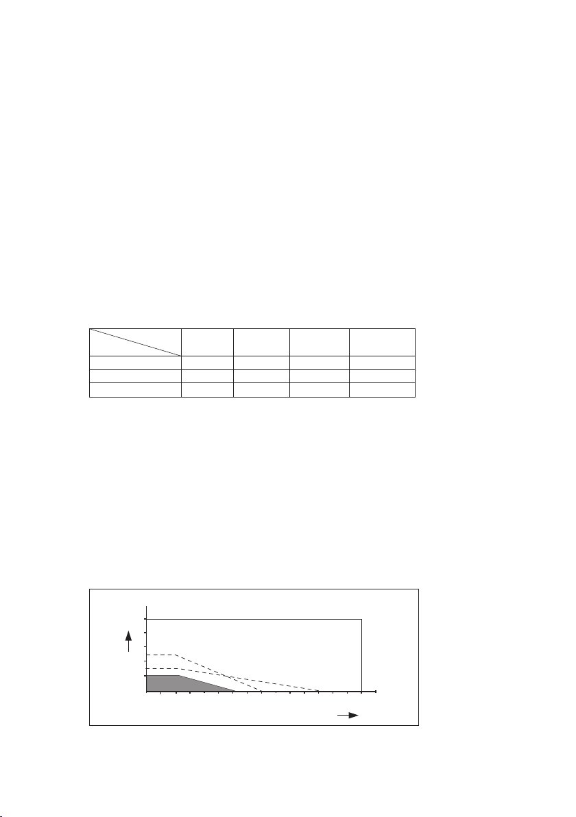
Pressure : see figure 2-1
Pressure/temperature class (figure 1)
10
BAR
8
6
PP
4
PVDF
2
0 20 40 60 80 100 120 140 160
PVC
SS
ºC
Fig. 2-1. Pressure/temperature class
IM12B6K2-01E-E
Page 4
4
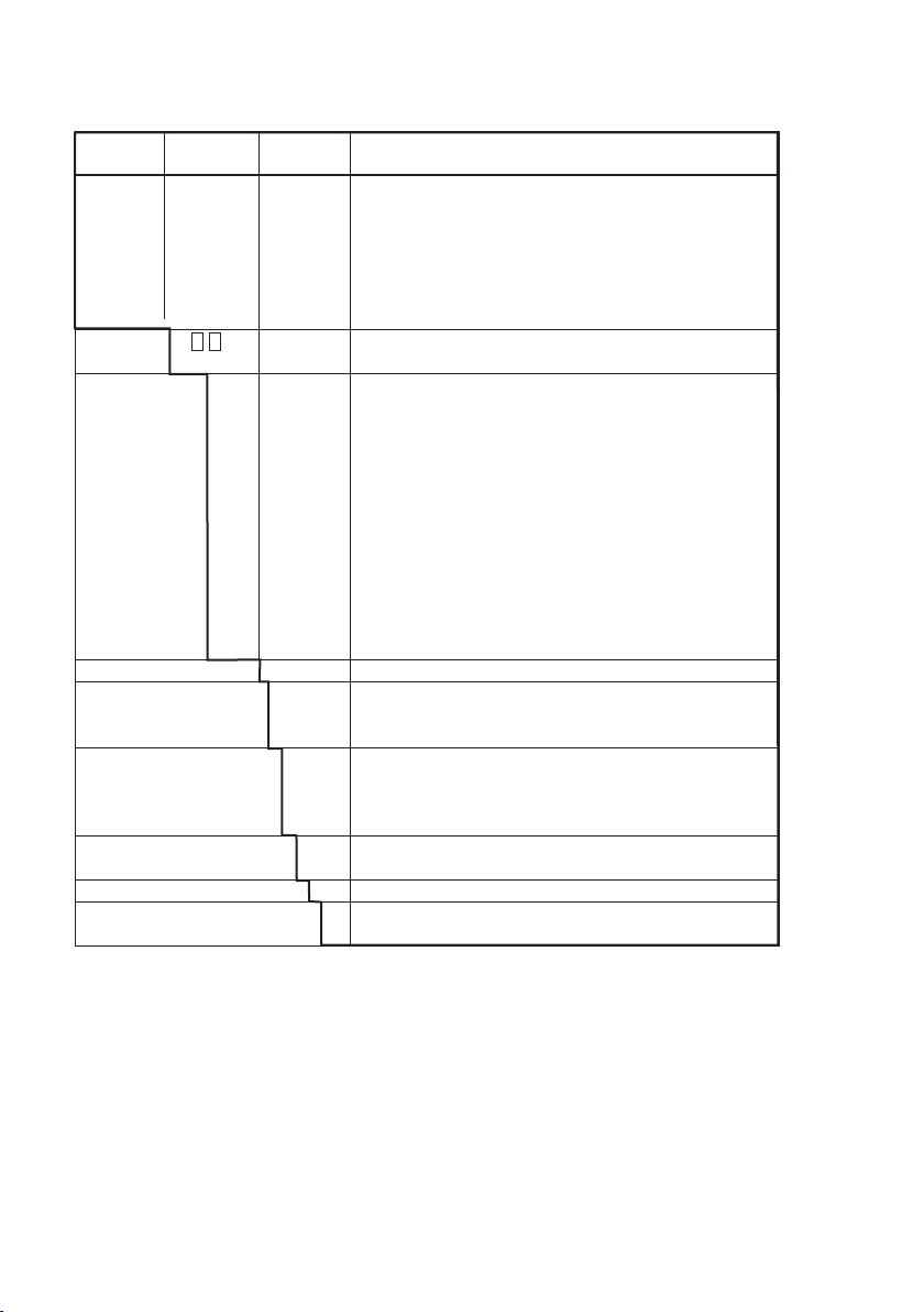
2-3. Model and codes
Model Suffix Option Description
Code Code Code
FD20F37 Immersion fitting, PVDF, 3 electrode mounting holes
FD20F47 Immersion fitting, PVDF, 4 electrode mounting holes
FD20P37 Immersion fitting, PP, 3 electrode mounting holes
FD20P47 Immersion fitting, PP, 4 electrode mounting holes
FD20S37 Immersion fitting, SS, 3 electrode mounting holes
FD20S47 Immersion fitting, SS, 4 electrode mounting holes
FD20V18(1 Immersion fitting, PVC, 1 electrode mounting holes
Immersion - Between 5 and 20 (in dm)
length(2 example 06=0.6 m.
Flange(3 -NF No flange
(Working -F1 Flange DN32 for 1 hole fitting
pressure -F2 Flange DN80 for 3 hole fitting PP
not more than -F3 Flange DN80 for 3 hole fitting PVDF
3 bar) -F4 Flange DN80 for 3 hole fitting SS
-F5 Flange DN125 for 4 hole fitting PP
-F6 Flange DN125 for 4 hole fitting PVDF
-F7 Flange DN100 for 4 hole fitting SS
-S1 Flange ANSI 11/4” 150Lbs for 1 hole fitting PVC
-S2 Flange ANSI 3” 150Lbs for 3 hole fitting PP
-S3 Flange ANSI 3” 150Lbs for 3 hole fitting PVDF
-S4 Flange ANSI 4” 150Lbs for 3 hole fitting SS
-S7 Flange ANSI 4” 150Lbs for 4 hole fitting SS
*A Style A
Options
Protectionhose /PH5 For 5,5 m cable
installation kit /PH10 For 10 m cable
Mounting kit /R For mounting (top) refillable electrodes with al long
glass shaft
/B For mounting Bellomatic reference and combined
electrodes
KCL reservoir(4 /K Electrode tubing is included (2,5 m)
(only in combintaion with /R)
Salt bridge /S For liquid which cannot stand contamination with KCL
Certificate /M 3.1 according EN-10-024 (DIN 50049 3.1)
for wetted metal parts
1. PVC is available in a 1-hole design only.
2. The immersion length of stainless steel fittings with a flange will be shortened by 35 mm
(refer to dimensional drawings).
3. Configuration of hole (see dimensional drawings 2-4). Working pressure not more than 3
bar. For higher pressure ratings please contact your local Sales Department of Yokogawa.
4. In combination with /R option only.
Notes:
a. Options are supplied with the fitting.
b. The available length of the electrode cables between fitting and converter or connection
box is cable length minus immersion length (L).
IM 12B6K2-01E-E
Page 5

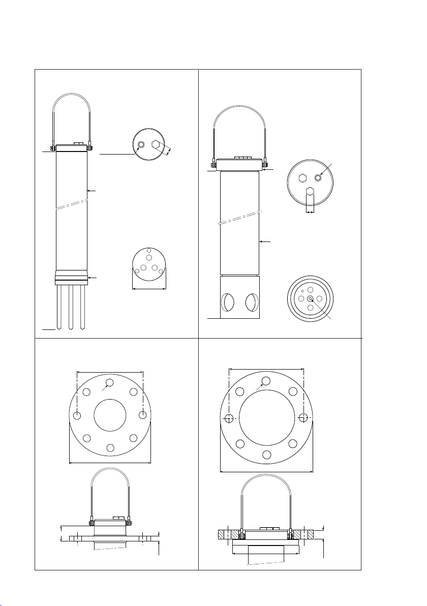
2-4. External dimensions
ø 30
ø 25
ø 40
L
ISO 228/2-G1/2
5
1-hole PVC
3-hole PP and PVDF
Flange Flange
ø D
ø dg
ø90
ISO 228/2-G 1/2
(2x)
ø75
ø k
dg
27
ø k
b
ø D
b
ø 125
IM12B6K2-01E-E
Page 6
6
ø130
ø110
27
M8
ISO 228/2-G1/2 (3x)
3-hole SS
ISO 228/2-G 1/2
2x
ø76
ø80
27
80
4-hole PP and PVDF
Flange Flange
ø k
ø k
35
IM 12B6K2-01E-E
dg
ø D
dg
ø D
b
ø 188
b
L
Page 7

7
L
ø 88
ISO 228/2-G 1/2
(3x)
27
M8
ø 100
35
b
ø D
ø k
4-hole SS
Flange
dg
L D k dg b
FD20-V18-..-NF 5-20dm
FD20-V18-..-F1 5-20dm 120 90 14 26
FD20-V18-..-S1 5-20dm 120 90 16 26
FD20-P37-..-NF 5-20dm
FD20-F37-..-NF 5-20dm
FD20-P37-..-F2 5-20dm 200 160 18 20
FD20-F37-..-F3 5-20dm 200 160 18 20
FD20-P37-..-S2 5-20dm 190 152.4 20 18
FD20-F37-..-S3 5-20dm 190 152,4 20 18
FD20-S37-..-NF 5-20dm
FD20-S37-..-F4 5-20dm 200 160 18 10
FD20-S37-..-S4 5-20dm 228,6 190,5 19 23,8
FD20-P47-..-NF 5-20dm
FD20-F47-..-NF 5-20dm
FD20-P47-..-F5 5-20dm 250 210 18 25
FD20-F47-..-F6 5-20dm 250 210 18 25
FD20-S47-..-NF 5-20dm
FD20-S47-..-F7 5-20dm 220 180 18 10
FD20-S47-..-S7 5-20dm 228,6 190,5 19 23,8
unit in mm
IM12B6K2-01E-E
Page 8

8
3. INSTALLATION
3-1. Selecting the installation site
It is important that, whatever method of
mounting is used, the point of measurement is
truly representative for the entire solution.
- Avoid an area where the measurement value
varies significantly.
- Ensure that the sensors are always immersed
in the process liquid (not dry).
GO OD
GO OD
HOR IZO NTAL
15 º
15 º
- When selecting the installation site, first check
that the liquid temperature and pressure
meets the sensors and fittings requirements.
- If the fitting is used in a tank with stirrer
or agitator, or if it is placed in a fast flowing
process, care must be taken that it
Fig. 3-1. Mounting position of sensors
INC ORR ECT
is adequately supported to prevent any
movement.
- Install the fitting in a site where it can be easily maintained.
The mounting position of the sensors must be within the area as shown in figure 3-1.
3-2. Installation
Before installing the immersion fitting, check that all parts and accessories were supplied by
Yokogawa.
Ensure that there is enough spare around to withdraw the fitting for calibration and maintenance.
3-2-1. “Hoisting eye” type mounting
On top of each fitting is a “hoisting eye” to withdraw from the process.
3-2-2. Flange mounting fitting
If ordered, the immersion fittings are supplied with a flange for fixing in a tank. The flange is
connected to the fitting as shown in the dimensional drawings. These drawings also show
the configuration of holes.
The max. pressure is 3 bar. For higher pressure ratings and other types of flanges please
contact your local Sales Department of Yokogawa.
Table 2. Flanges being used as a standard
Type Material TypePP Material DN Thickness
fitting fitting flange flange flange
1-hole PVC glue-flange PVC 32
3-hole SS weld-flange SS 80 10 mm
4-hole SS weld-flange SS 100 10 mm
3-hole PP collar-bush + PP + 80
lap-joint flange PP (steal inlay)
4-hole PP collar-bush + PP + 125
lap-joint flange PP (steal inlay)
3-hole PVDF collar-bush + PVDF + 80
lap-joint flange PP (steal inlay)
4-hole PVDF collar-bush + PVDF + 125
lap-joint flange PP (steal inlay)
IM 12B6K2-01E-E
Page 9

9
10 cm
colour
marker
colour
marker
outer
screening
white
core red
inner
screening
blue
Cable nut
3-3. Cables and sensor mounting
Before mounting a sensor and/or accessory
the cables must be passed through the
fitting. When mounting Yokogawa sensors
the electrode cables, model WU20(D),
should be used (see figure 3-2). Length 1,
2, 51/2, 10, 15, 20 or 25 m.
Model code Suffix code Description
WU20(D) Electrode cable
Type -PC COAX
-LT TRIAX
Length in mm 01 1 mtr
02 2 mtr
05 51/2 mtr
10 10 mtr
3-3-1. 1-Hole fitting
Unscrew the protector from the lower end
and the nut with glands from the top end of
15 15 mtr
20 20 mtr
25 25 mtr
the fitting. Mount the cable and sensor as
shown in figure 3-3.
Type WU20-PC Type WU20-LT
Cable nut
Cable nut
10 cm
10 cm
colour
marker
colour
marker
COAX
screen
blue
Fig. 3-2. Electrode cables
colour
marker
core
red
TRIAX
inner
screening
blue
core red
colour
marker
outer
screening
white
IM12B6K2-01E-E
Page 10

10
10 cm
colour
marker
colour
marker
outer
screening
white
inner
screening
blue
Cable nut
Type WU20D-PC
Cable nut
10 cm
screen
blue
COAX
colour
marker
colour
marker
O-rings
(11x3)
core
red
Type WU20D-LT
Cable nut
10 cm
colour
marker
colour
marker
TRIAX
inner
screening
blue
core red
outer
screening
white
Attention:
Ensure that the cable has slack remaining
in the fitting so that sensor replacement is
simplified. To prevent damage of the O-rings
the nut and glands must be screwed
HAND-TIGHT to the fitting. Prepare the
sensor to be used in accordance with the
directions for use. After that mounting can
be made as shown in fig. 3-3.
Attention:
To prevent fouling of the contacts, it is
recommended to screw the electrode
cable on the electrode as soon as possible.
Ensure that there is no moisture or dust in
the connection sensor-cable.
Electrode cable model WU20
Fig. 3-3. Mounting a cable and sensor
in a 1-hole fitting
IM 12B6K2-01E-E
Page 11

11
3-3-2. 3-Hole and 4-hole fitting
Unscrew the protector complete with
electrode holder from the lower end of the
fitting (see figure 3-3).
Unscrew the cap of an electrode mouting
set. Pass the electrode cable through this
cap and after that through the fitting.
Mount the other electrode cables in a
similar manner. Pass the electrode cables
and the liquid earth cable through a hose
connection, which is delivered with the
fitting in a plastic pocket.
Attention:
Ensure that the cables have slack remaining
in the fitting. The plug of the electrode cable
must be ± 15 cm out of the lower end so
that torsion will be avoided and
sensor mounting is simplified.
Before screwing the hose connection into
place HAND-TIGHT, some glue must be put
to the screw end (see figure 3-4).
Prepare the sensors to be used in
accordance with the directions for use and
mount them in the fitting as shown in fig.
3-4. For stable measurements the glass
and reference electrode should be mounted
in the holes nearest to the earth connection.
As delivered the O-rings (2x) for water-tight
sealing in the mounting holes are on the
blanking plugs. These plugs are for unused
holes.
To prevent fouling of the contacts, it is
recommended to screw the electrode cable
on the electrode as soon as possible.
ENSURE THAT THERE IS NO MOISTURE
OR DUST IN THE CONNECTION CABLEELECTRODE.
Liquid earth
cable
Protection
hose
Glue
Electrode cable
model WU20(D)
Electrode
O-rings
(11x3)
Attention:
To have slack remaining in the fitting the
protector complete with electrode holder
should be turned to the left before fixing
HAND-TIGHT to the fitting.
Fig. 3-4. Mounting cables and sensors
in 3-hole and 4-hole fittings
IM12B6K2-01E-E
Page 12
12
4. MOUNTING OF ACCESSORIES
4-1. Mounting kit (FP20-S13(D))
Using this mounting kit a SR20(D)-AC32
reference electrode of Yokogawa can be
mounted in a fitting (see figure 4-1.).
For atmospheric conditions the mounting kit
can be used also for combined electrodes,
types SC29-PTC54.
Electrodes to be used*
Order nr. Description
SR20(D)-AC32 Reference electrode
SC29-PTC54 Combined redox/reference
electrode
* For specifications of the electrodes see
seperate sheets.
Parts and accessories
Order nr. Description
FP20-S13 Mounting kit for SR20-AC32
(10x)
FP20-S13D Mounting kit for
SR20(D)-AC32 (10x)
K1500HC Rubber rings for FP20-S13
(10x)
K1500GE O-rings for SR20D-AC32
electrode (5x)
K1500GF 250 ml, KCI-solution (1 m)
K1500VA 250 ml, KCI-solution (3,3 m)
K1500GG 250 ml, KCI-solution (1 m)
thickened
K1520VN 250 ml, KCI-solution
(3,3 m) thickened
Ring
K1500HC
Bellomatic
electrode
K1500BZ
IM 12B6K2-01E-E
Fig. 4-1. Mounting of a BELLOMATIC
electrode
Page 13

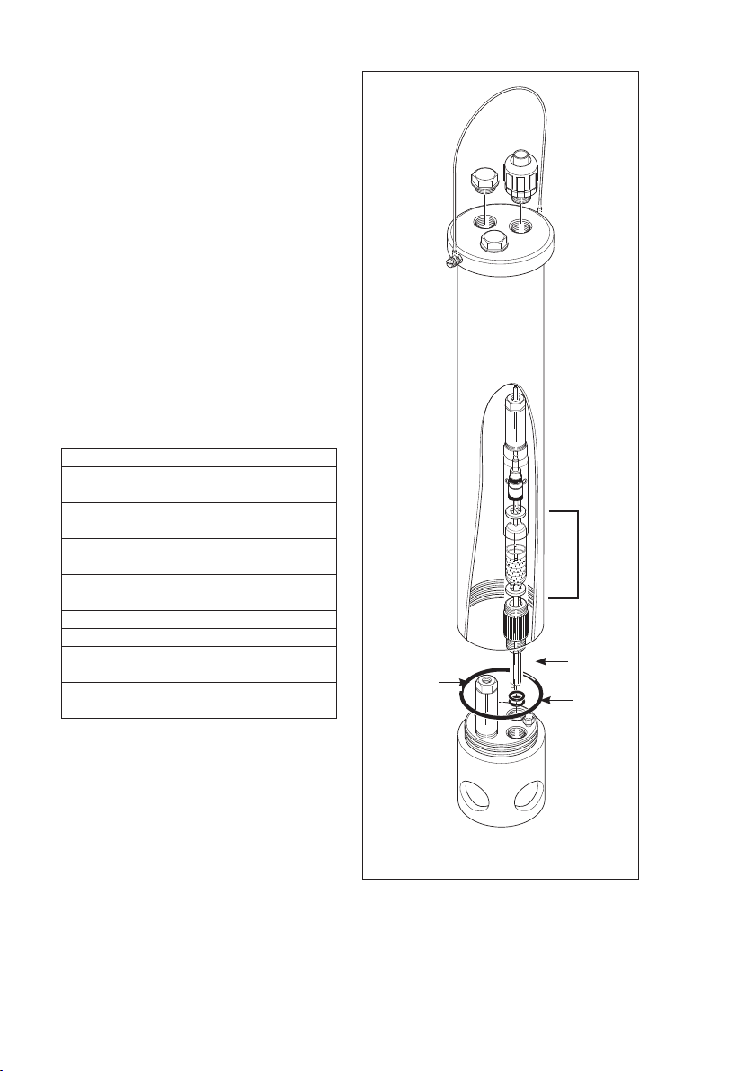
4-2. Mounting kit (order nr. K1500BY)
This mounting kit replaces the standard
electrode mounting set so that Yokogawa
refillable electrodes with a long glass shaft
can be mounted in a fitting.
The mounting set may be used at process
pressures up to 3 bar. Higher pressure
ratings require the standard mounting set
and consequently, electrodes with DINdimensions.
Figure 4-2 shows the mounting.
Note:
The pressure on the KCI-solution must
always exceed the liquid pressure.
The refillable electrodes can be connected
to a KCI-reservoir via a silicone tubing
(see figure 4-2). The pressure on the
KCI-solution and consequently, the liquid
outlet of the electrode can be increased by
mounting the reservoir on top of the fitting.
This prevents penetration of the process
liquid into the electrode.
Electrode to be used*
Order nr. Description
SR20-AC52 Reference electrode
SR20-AS52 Reference electrode
SC21-AGC52 Combined pH/ref. electrode
SC21-ASC52 Combined pH/ref. electrode
* For specifications see seperate sheets.
Parts and accessories
Order nr. Description
K1500BY Mounting kit
K1500FZ O-ring for mounting kit
K1500GF 250 ml, KCI-solution (1 m.)
K1500GG 250 ml, KCI-solution (1m.),
thickend
KCI-Reservoir
K1500FU
Silicone tubing
K1500GA
13
Electrode
O-Rings
K1500BZ
Fig. 4-2. Mounting of refillable electrodes
with a long glass shaft
IM12B6K2-01E-E
Page 14

14
4-3. Cleaning systems
The standardised design of fittings makes it
possible to mount cleaning systems directly.
The 4-hole types are especially designed for
these applications.
The Yokogawa program includes two
different types of cleaning systems
(see figure 4-3):
- brush cleaning
(electrically or pneumatically driven)
- chemical cleaning
Fig. 4-3a. Brush Cleaning Fig. 4-3b. Chemical Cleaning
4-3-1. Selection criteria
Cleaning system Mechanical Chemical
Applications with Brush Acid Base
Oils, fats
Resins (wood, pulp) X
Emulsions of latex X
Fibers (paper, textile) X
Crystaline precipations (carbonates) X XX
Amorpheus precipations (hydroxides) X XX
IM 12B6K2-01E-E
Page 15

15
4-3-2. Brush cleaning
The brush of this cleaning system wipes
across the glass membrane of the
Motor
K1520NF
Cable
model
WU20(D)
O-rings (11x3)
(K1500BZ)
Brush holder
K1520NG
Control unit
electrode every 30 seconds. Electrically or
pneumatically driven versions are available.
Figures 4-4a and 4-4b show the mounting.
Protection hose
K1520NC
Tubing
K1520NA
Control unit
Piston unit
K1520NH
O-rings (11x3)
Brush holder
K1520NG
Fig. 4-4a. Mounting a brush cleaning
(electrically driven) FC20-VE
Fig. 4-4b. Mounting a brush cleaning
(pneumatically driven) FC20-VP
Parts and accessories
Order nr. Description
FC20-VE Brush cleaning (electrically driven)
WU20-PC Electrode cable (to be used as a supply cable for the motor)
Length: 1, 3, 5, 10, 15, 20 or 25 m.
FC20-VP Brush cleaning (pneumatic driven)
K1520NB Brush
K1520NA Tubing (ø 4 mm) for FC20-VP for connection between piston and supply unit
* Detailed specifications are on seperate sheets.
IM12B6K2-01E-E
Page 16
16
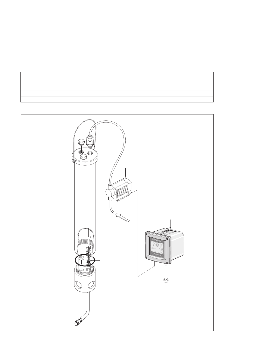
4-3-3. Chemical cleaning
The chemical cleaning system is based on periodically spraying of a cleanser on to the
glass membrane of the electrode. The cleanser to be used, the cleaning frequency, etc. are
highly dependent on the liquid to be measured. The cleaning period and frequency can be
adjusted on a control unit. The mounting procedure is shown in figure 4-5.
Parts and accessories
Order nr. Description
K1520FK Tubing ø1/4” for chemical cleaning (1 m)
K1547PA Complete chemical cleaning system HCN2, HCN3 for 2-hole and 3-hole fittings
K1547PB Complete chemical cleaning system HCN4, for 4-hole fittings
K1547PP EPDM spraying valve nozzle 5 sets (for all HCN- chemical cleaning systems)
* Detailed specifications are on seperate sheets.
PUMP
(type dependent on application)
Spray unit HCN
Fig. 4-5. Mounting a spray unit
IM 12B6K2-01E-E
TUBE
O-RINGS
(11 x 3)
Control unit
Page 17

4-4. Salt bridge
This reference electrode/salt bridge
combination allows the measurement of
pH and ORP (Redox) potentials with normal
electrodes in those cases when:
A. excessive contamination of the flow
diaphragm is expected. The flow of the
reference liquid through the diaphragm is
increased by pressurising the container.
Consequently, the contamination rate will
decrease.
B. the process to be measured cannot
stand contamination with KCI. The
salt bridge can be filled with several
electrolytes, e.g. KNO3.
C. measurement has to be performed at
pressures up to 10 bar and temperatures
up to 100 °C. As the container with
reference liquid can be pressurised.
FLOW TUBE (A)
Material : glass
Flow diaphragm : ceramic, PTFE or sleeve
Connector : Ryton R4
TUBING (B)
Material : nylon
Diameter : 1/4” o.d.
Length : 2 mtr.
CONTAINER (C)
Container : PVC, PVC (transparent)
Mounting set : Ryton R4
O-ring : silicone
Connection : nylon
Weight : approx. 300 g.
Mounting : wall mounting (support
with hole for screw M5)
Temperature/
pressure ratio : max. 200 kPa
(2 bar) at 100°C
Parts and accessories
Order nr. Description
SB20-VC Salt bridge with ceramic junction
SB20-VP Salt bridge with porous PTFE
junction
SB20-VS Salt bridge with glass sleeve
junction
K1500DX 5m tubing for SB20
K1500BW flow tube for SB20-VC
K1500EE flow tube for SB20-VP
K1500EF flow tube for SB20-VS
17
REFERENCE
ELECTRODE
Fig. 4-6. Mounting the salt bridge
Note: The reference electrode must be
ordered seperately.
4-5. Protection hose installation kit
The protection hose installation kit is for
protection of electrode cable and/or tubing
between fitting and converter, connecting
box, supply unit, etc. The hoses can be
mounted directly to the hose connections(s)
on top of each fitting. Clamps for fixing are
part of the installation kit.
Parts and accessories
Order nr. Description
K1500DN Protection hose kit 3 m
K1500DP Protection hose kit 5,5 m
K1500DQ Protection hose kit 10 m
K1500DR Protection hose kit 15 m
K1500DS Protection hose kit 20 m
IM12B6K2-01E-E
Page 18

18
5. MAINTENANCE AND INSPECTION
5-1. Cleaning and fitting
Usally no cleaning is necessary.
5-2. Inspection of the O-ring seal
The O-ring seal used in the wetted parts of the fitting is made of silicone rubber which has
superior resistance to corrosion and is suitable for use with most process liquids.
Usually no periodically inspection is necessary. To prevent trouble, replace the O-ring seal
periodically, e.g. every year.
Note: For chemical resistance of the used material refer to General Specifications sheet
GS 12B6K2-01E-E.
6. SPARE PARTS
Order nr. Description
K1500GR O-rings (11x3) for electrode mounting (8 pieces)
K1500FU Set O-rings for 3-hole fitting (PP and PVDF)
K1500FB (viton) Set O-rings for 3-hole fitting (PP and PVDF)
K1500FA (EPDM) Set O-rings for 3-hole fitting (PP and PVDF)
K1500GV Set O-rings for 4-hole fitting (PP and PVDF)
K1500FF (viton) Set O-rings for 4-hole fitting (PP and PVDF)
K1500FE (EPDM) Set O-rings for 4-hole fitting (PP and PVDF)
K1500GW Set O-rings for 3-hole fitting (SS)
K1500FD (viton) Set O-rings for 3-hole fitting (SS)
K1500FC (EPDM) Set O-rings for 3-hole fitting (SS)
K1500GX Set O-rings for 4-hole fitting (SS)
K1500FH (viton) Set O-rings for 4-hole fitting (SS)
K1500FG (EPDM) Set O-rings for 4-hole fitting (SS)
K1500DQ 10 m protection hose and glands
K1500DP 5,5 m protection hose and glands
FP20-R12 Electrode mounting set (Ryton R4) (1x)
FP20-R12M Mounting set (Ryton R4) (12x)
FP20-S12 Electrode mounting set (SS)
K1500FV Liquid earth cable (10 m)
K1500DU Liquid earth cable (25 m)
K1500FU KCI-reservoir
WU20-PC01 COAX-cable (1 m) for single electrode
WU20-PC02 COAX-cable (2 m) for single electrode
WU20-PC05 COAX-cable (5,5 m) for single electrode
WU20-PC10 COAX-cable (10 m) for single electrode
WU20-PC15 COAX-cable (15 m) for single electrode
WU20-PC20 COAX-cable (20 m) for single electrode
WU20-PC25 COAX-cable (25 m) for single electrode
WU20-LT01 TRIAX-cable (1 m) for combined electrode
WU20-LT02 TRIAX-cable (2 m) for combined electrode
WU20-LT05 TRIAX-cable (5,5 m) for combined electrode
WU20-LT10 TRIAX-cable (10 m) for combined electrode
WU20-LT15 TRIAX-cable (15 m) for combined electrode
WU20-LT20 TRIAX-cable (20 m) for combined electrode
WU20-LT25 TRIAX-cable (25 m) for combined electrode
IM 12B6K2-01E-E
Page 19

1-Hole PVC
Note
This fitting has no liquid earth connection
19
3-Hole PP and PVDF 4-Hole PP and PVDF 3-Hole SS 4-Hole SS
IM12B6K2-01E-E
Page 20

YOKOGAWA ELECTRIC CORPORATION
World Headquarters
9-32, Nakacho 2-chome, Musashino-shi
Tokyo 180-8750
Japan
www.yokogawa.com
YOKOGAWA CORPORATION OF AMERICA
2 Dart Road
Newnan GA 30265
USA
www.yokogawa.com/us
YOKOGAWA EUROPE BV
Euroweg 2
3825 HD AMERSFOORT
The Netherlands
www.yokogawa.com/eu
YOKOGAWA ELECTRIC ASIA Pte. LTD.
5 Bedok South Road
Singapore 469270
Singapore
www.yokogawa.com/sg
YOKOGAWA CHINA CO. LTD.
3F Tower D Cartelo Crocodile Building
No.568 West Tianshan Road Changing District
Shanghai, China
www.yokogawa.com/cn
YOKOGAWA MIDDLE EAST B.S.C.(c)
P.O. Box 10070, Manama
Building 577, Road 2516, Busaiteen 225
Muharraq, Bahrain
www.yokogawa.com/bh
Yokogawa has an extensive sales and
distribution network.
Please refer to the European website
(www.yokogawa.com/eu) to contact your
nearest representative.
IM 12B6K2-01E-E
Subject to change without notice Printed in The Netherlands, 07-1008 (A) I
Copyright ©
 Loading...