

Page 1
Technical
Information
Range-free Multi-controller
FA-M3 R Overview
TI 34M6A01-01E
2000.5 2nd Edition
Page 2

This document is based on the version of FA-M3 R as of May 2000.
For details about the current version of FA-M3 R, please contact your
nearest distributor or agency.
Page 3

CONTENTS
Introduction to FA-M3 ………………..………………………………………………………... 1
FA-M3 Features ……………………………………………………………………………… ..... 2
Ultra-fast Processing Speed………..………………………………………………………... 3
Comparison with Competitors……..……………………………………………………….... 4
Compact Size. ……………………..………………………………………………………….. 5
Universal Range.……………………..……………………………………………………...... 6
Multiple CPUs .………………………………………………………………………………....7
Sequence CPU Modules.…………………………………………………………………....8
(F3SP05-0P, F3SP21-0N, F3SP28-3N, F3SP38-6N, F3SP53-4H, F3SP58-6H, F3FP36-3N)
BASIC CPU Modules……………………………………………………………………….. 9
(F3BP20-0N, F3BP30-0N)
Easy Real-time Processing with BASIC ………………………………………………… 10
Program Development Tools
FA-M3 Programming Tool WideField
Ladder Programming Tool Designed for Engineers………………………………. 11
Object Ladder…………………………………………………………………………. 12
Program Component…………………………………………………………………. 13
Index View…………………………………………………………………………….. 14
Collective Change of I/O Positions ………………………………………………… 15
Logical Design by Tag Name……………………………………………………….. 16
Group Tag Name……………………………………………………………………... 17
Advantages of Windows Environment……………………………………………... 18
Flexible Operability …………………………………………………………………...19
Sophisticated Debugging Functions………………………………………………... 20
Enriched Help…………………………………………………………………………. 21
BASIC Programming Tool M3 for Windows………………………………………………. 22
Outstanding Maintenance Support Functions ……………………………………………. 23
Remote OME …………………………… ……………………………………… …………. 24
Remote OME via Ethernet ………………………………………………………………...25
Remote OME Using Commercially-available Modem …………………………………. 27
System Log ……………………………………………………………………………….... 28
User log …………………………………………………………………………………….. 29
Sampling Traces…………………………………………………………………………….30
Analog Input/Output Modules ……………………………………………………………….31
(F3AD04-0N, F3AD08-1N, F3DA02-0N, F3DA04-1N, F3DA08-5N)
Temperature Control Modules ……………………………………………………………... 32
(F3CT04-0N, F3CT04-1N, F3CR04-0N, F3CR04-1N, F3CV04-1N)
Positioning Modules for Controlling Every Type of Motor ……………………………... 33
F3NC11-0N and F3NC12-0N Advanced model Positioning Modules
with Positioning Pulse Output ………………………………………………………..34
F3NC51-0N and F3NC52-0N Positioning Modules with Analog Voltage Output…….35
TI 34M6A01-01E I
Page 4

Applications of Personal Computer Link Interface………………………………………...36
(Connection with personal computer/Display)
Personal Computer Link Modules ………..…………………………………………………37
(F3LC11-1N, F3LC11-2N)
Personal Computer Link via Programming Port……………………………………………38
(F3SP05-0P, F3SP21-0N, F3SP28-3N, F3SP38-6N, F3SP53-4H, F3SP58-6H)
Ethernet Interface Module………..……………..……………………………………………39
(F3LE01-5T)
FA Link H Module ………..……………..………..…………………………………………..40
(F3LP02-0N)
Fiber-optic FA Link H Module………..……………..………………………………………..41
(F3LP12-0N)
UT Link Module………..……………..………..……..……………………………………….42
(F3LC51-2N)
Multi-Link Module ………..……………..……..……..……………………………………….43
(F3LC21-1N)
GP-IB Communication Module ………..……………..………..……. .…………………….44
(F3GB01-0N)
RS-232-C and RS-422/485 Communication Modules (1) ………….. …………………..45
(F3RZ81-0N, F3RZ91-0N)
RS-232-C and RS-422 Communication Modules (2) ………..……………………………46
(F3RS22-0N, F3RS41-0N)
FA-M3 Value………..……………..……..……..………..……………………………………47
(F3SC21-1N)
Fiber-optic FA-bus Module………..………………..………………………………………..48
(F3LR01-0N)
Fiber-optic FA-bus Type 2 Module………...……..………………… ……… ………………49
(F3LR02-0N)
DeviceNet Interface Module………..……………..…………………………………………50
(F3LD01-0N)
24 V DC Power Supply Module………..……………..……………………………………..51
(F3PU26-0N)
Market Standard Connectors………..……………..……………………………………......52
TI 34M6A01-01E II
Page 5
P
P
L
L
C
C
Introduction to FA-M3
From EVOLUTION to REVOLUTION
The FA-M3 has rebor ned as the FA-M3 R,
to revolutionize the users' equipment.
for Revolution!
FA-M3 R is a new generic name for FA-M3 controllers containing one or
more of the brand new, ultra-fast four CPU modules.
FA-M3 R can simply be called the
FA-M3 R and FA-M3 have upward compatibility.
The design concept was to increase the speed of the FA-M3. The new high-
speed Instruction-Process-Response-Scan, or High-speed IPRS, in the FA-M3 R
was designed to achieve this objective.
Extensive studies were conducted to meet every requirement including ultra-high-
speed control, steady dispersion-free control and improved networking functions
including link control. The FA-M3 R is Yokogawa's ideal controller for nextgeneration equipment, delivering even greater accuracy and productivity.
"
M3R".
TI 34M6A01-01E
Instruction
Process
Scan
High speed
Response
1
Page 6
P
P
L
L
C
C
FA-M3 R Features
Ultra-fast Processing Speed
20K steps of ladder program scanned per millisecond
Minimum scan time of 200 µs
Sensor control function with constant scan from 200 µs
Quick response from input to output
Quick response time 100 µs to an interrupt signal
Ultra-compact Size
The compact, 147 (W) x 100 (H) x 88 (D) mm size
handles 192 points.
Universal I/O Range
Can control up to 8, 192 points and contain devices of up
to 310K words per system.
Capabilities of a high-end PLC at the cost of a low- or
mid-range PLC
In case of 1000-2000 I/O points, the list price becomes
one third to a hal f against other vendor’s PLC
* I ndicates the performance when running a program that contains basic instructions and application instructions in average ratios; does not guara ntee that all
the user's program wi ll run at this speed.
** Acronym of rem ot e Operation Maintenance and Engineering proposed by Yokogawa Electric Corporation.
Outstanding Maintenance Support Functions
*
Remote OME**function using public phone line and Ethernet
Diagnostic based on error log and user log
Diagnostic based on sampling trace
Common I/O mod ule spares for all system regardless of I/O
range
Multi-CPU
Tasks can be divided by multiple ladder CPUs
Data processi ng by the BASIC CPU
PC applications run by the AT-compatible CPU
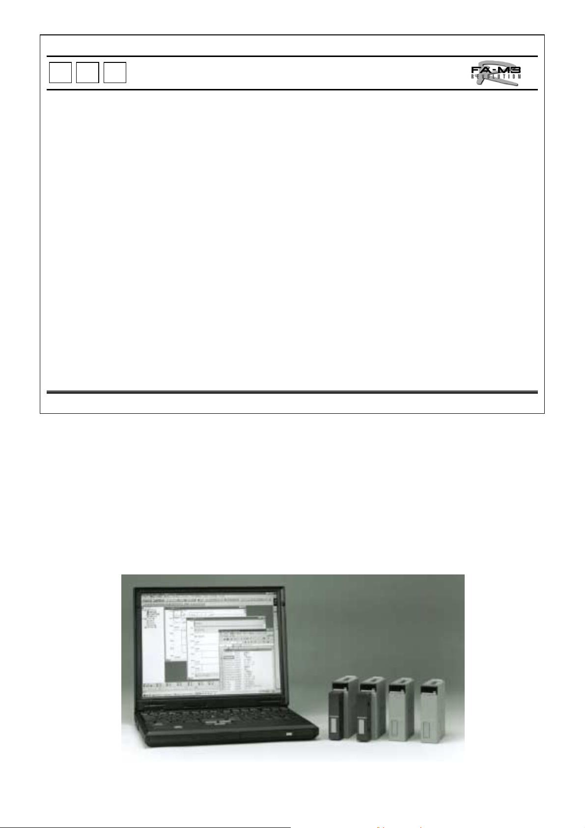
FA-M3 Programming Tool WideField
Object ladder, a new programming method succeedin g to
structured programming
Blocks and macros can be code d independently, t hus
drastically increasing reusability.
Increased efficiency of reuse with improved visibility
Easy data exchange wit h W i ndows- bas ed appli c ati ons
BASIC Programming Tool M3 for Windows
Convenient BASIC program development under the Windows
environment
The FA-M3 R outclasses the capabilities of today's PLCs and offers the
functionality, performance, a choice of languages and expandability
provided by a microcomputer board.
No more tedious quality control of huge variety of boards or
discontinuation of parts - the user can concentrate on adding value to
equipment.
TI 34M6A01-01E
2
Page 7
P
P
L
L
C
C
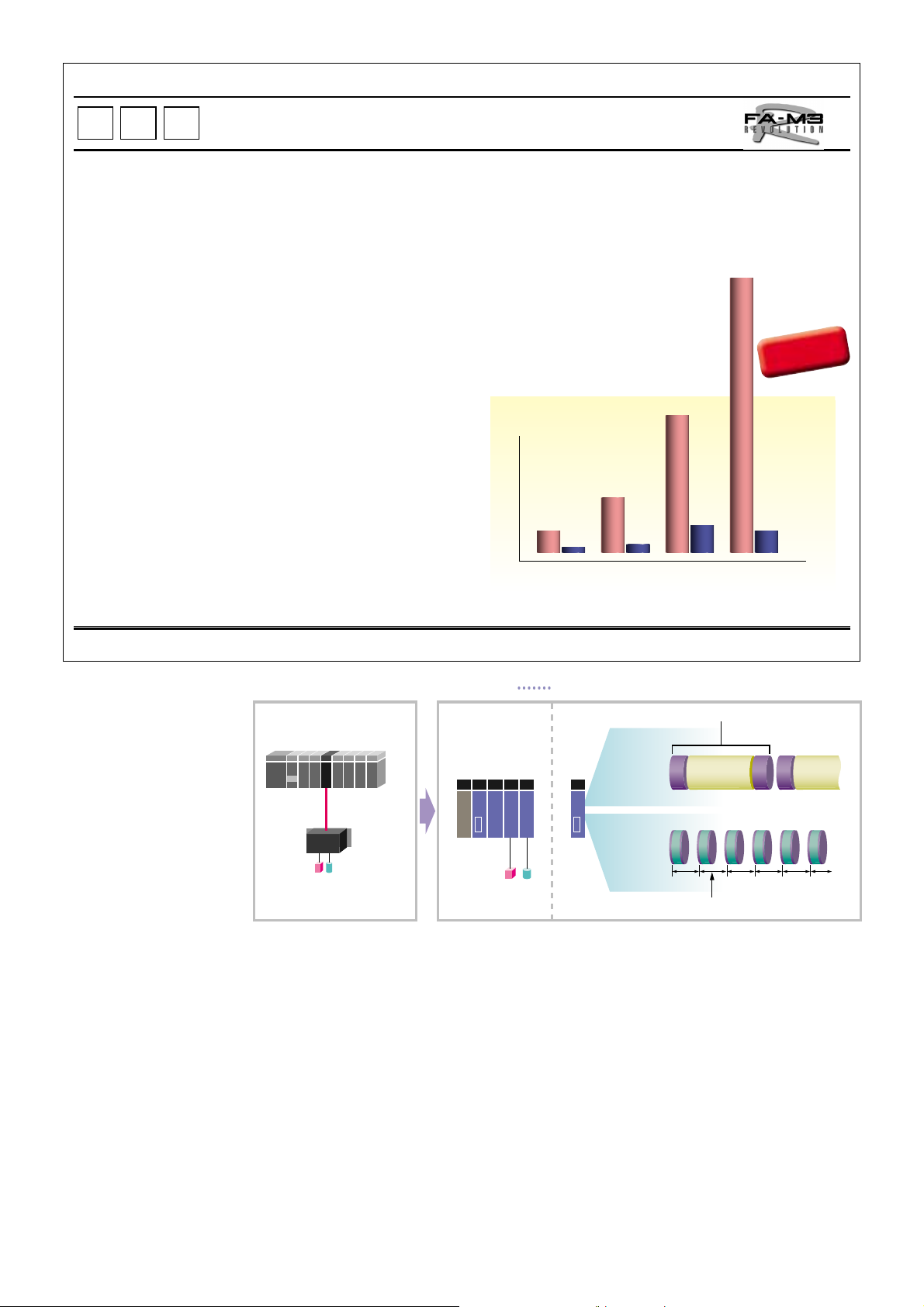
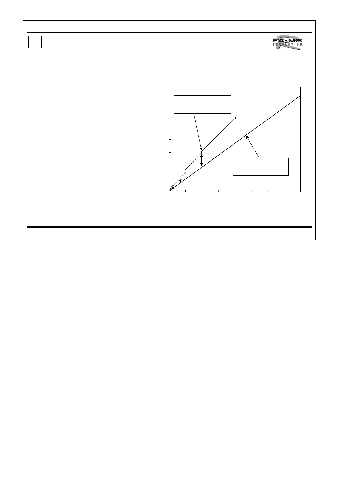
Ultra-fast Processing Speed
World's fastest processing speed realized by triple processors.
20K steps of ladder program scanned per milli second.
Minimum scan time of 200 µs.
The FA-M3 R del ivers high-speed in all aspects, running a 20K st eps of program in on e
millisecond (ratio of application instructions used: 50%). Actual applications for to day's
functionally-enhanced equipme nt contain a larger ratio of application instructions. For
such applicati ons, the FA-M3 R achieves at leas t ten times the performance of the
former CPU modules for the FA-M3.
The graph on the right shows examples of perform ance improvement s.
4
Average number of
Instruction executed
Molding
machine
* In comparison to the former CPU module of Yok ogawa with the actual applications
9.8
Sorting
machine
Application Type
*
10.8
max.10 times
faster*
4.1
F3SP58
F3SP35
Picking
machine
1: Compared whith Our Conventional CPU
Cleaning
machine
1
● With conventional PLC
PLC/
sensor controller
Sensor actuator
Quick response from in put to outp ut
• Ultra-quick response time: 100 µs
F3XD08-6F, F3XD16-3F, F3XD32-3F/4F,
F3XD64-3F/4F (with 32 input points)
• Ultra-quick response to input: 10 µs
F3XD16-3H (when used with the F3SP28,
F3SP38, F3SP53 or F3SP58)
• Output shutoff function added:
F3YD64-3F, F3WD64-3F/4F (with 32 output
points)
● With FA-M3 R
Sensor Control Function
The number of PLC units can be reduced since two ladder programs
can be executed by one CPU module.
1 scan
Main scan
High-speed
constant
scan
constant scan : Min. 200 µs
• One CPU can carry out a high-speed constant
scan (from 200 µs) independently besides the
normal scan.
• The same CPU also achieves a quick
response.
Faster Response to Interrupt Signal
• DC input module allows quick response of 100
µs to an interrupt input
• Swift response to a change in input level to
implement instantaneous high-speed control
TI 34M6A01-01E
3
Page 8
P
P
L
L
C
C
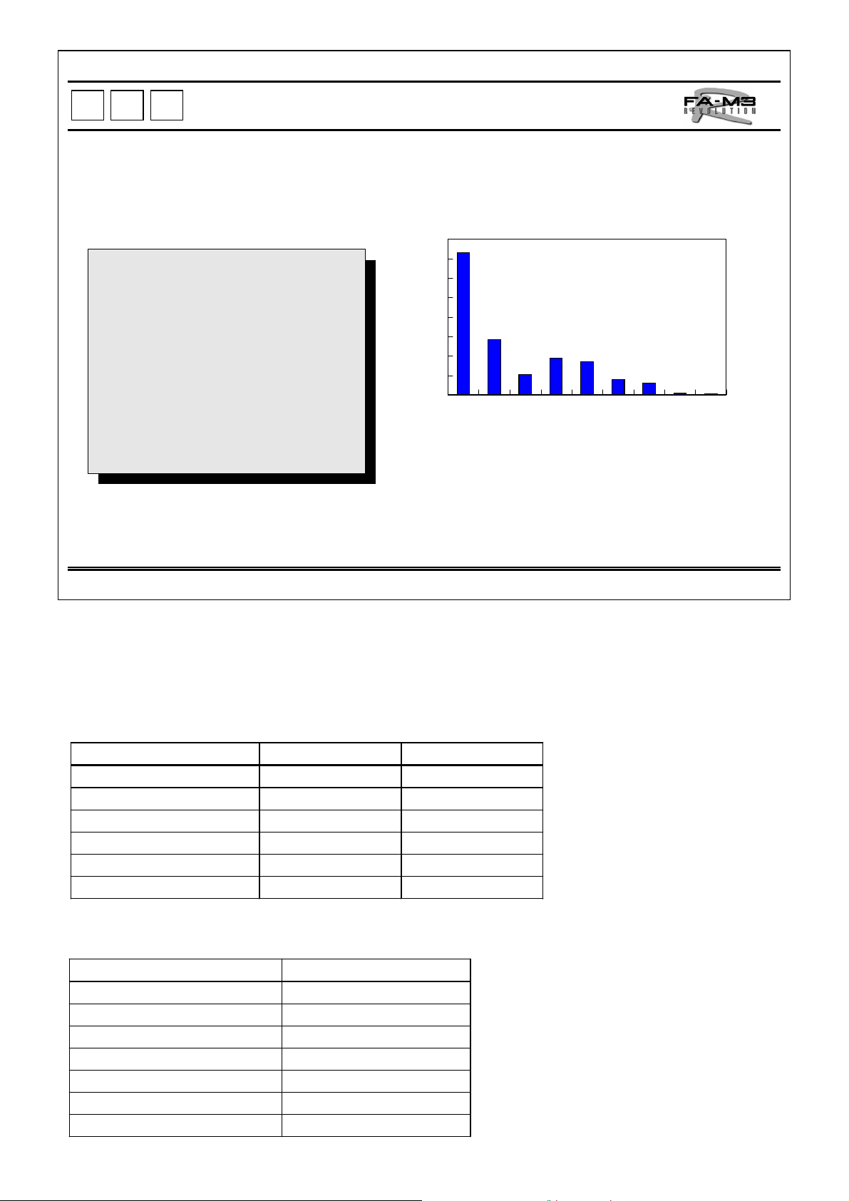
Comparison with Competitors
Due to the ultra-fast pro c es sin g speed, there's no nee d to
consider the processing time when programming.
Why is high-speed processing necessary?
To carry out complicated calculations (with
•
application instructions) quickly
To stabilize mechanical control of higher
•
speed for higher productivity
To allow human-interface and diagnostic
•
programs to be enhanced, thus providing an
easier interface for the operator
To reduce unstable actions during each scan
•
time by network servicing
* Execute d i nstructions mea ns t he aver age number of inst r uct i o ns executed in 1 µsby PLC.
Ultra-fast Execution of Instructions
Executed*
16.00
14.00
12.00
10.00
8.00
6.00
4.00
2.00
0.00
Comparison of Processing speed
14.50
5.62
3.80
3.54
1.52
Model of
Model of
Model of
company A
company A
company B
SP53/58
1.83
SP21
SP28/38
High-speed PLC CPU
Price: 200,000 to
550,000 yen
1.33
0.04
0.02
Model of
Model of
General PLC CPU
Price: 60,000 to
200,000 yen
company A
company B
Model of
company B
Basic instruction: Min. 0.0175 µs
Application instruction: Min 0.070 µs
Comparison with Yokogawa's Former CPU Module for Basic
Instructions
Instruction New SP53 Former SP35
LD, AND, OR 17.5 to 35 ns 90 ns
Timer 175 ns 360 ns
Transfer 70 ns 180 ns
Comparison 70 ns 180 ns
Addition, subt raction 105 ns 270 ns
Logic operator 105 ns 270 ns
Comparison with Yokogawa's Former CPU Module for Application
Instructions
Instruction SP58 vs. SP35
Transfer between file registers 74.1 times faster
Index modification (LD) 10.7 times faster
Index modification (MOV) 30.4 times faster
Read/write 6.4 times faster
Timer update 6.7 times faster
BMOV/BSET 12.8 times faster
FOR-NEXT 7.7 times faster
TI 34M6A01-01E
4
Page 9
P
P
L
L
C
C
Compact Size
Postcard-size Controller
Why does a controller need to be smaller?
• To provide ample room for additional modules
• To allow installation of the controllers without affecting the machine design and
safety of the user factory (al lowing per s pe c tive facilities)
• To help standardize control panels
• To reduce the size of the control panel to be min imized regardless of t he
controller scale
• To reduce costs
Duct
Other
manufacturer's
PLC
Duct
Relays, conductors, etc.
Design concept: PLC is a subs ti tu te for relays
The FA-M3 R is packaged into the size of usual relays and conductors, and is designed for ins tallation in the
same row with those inside a panel, thus allowing effective internal design of the panel.
Dimensions
Base
Module
F3BU04-0N 4 100 x 147 88.5
F3BU06-0N 6 100 x 205 88.5
F3BU09-0N 9 100 x 322 88.5
F3BU13-0N 13 100 x 439 88.5
F3BU16-0N 16 100 x 537 88.5
* Dimensions of a base module with I /O modules installed in it (excluding c onnectors and terminals bl ocks )
Slots
Mounting
Dimensions
(mm)
Depth of
Module
*
(mm)
Waste space
Duct
FA-M3 R
TI 34M6A01-01E
5
Page 10
P
P
L
L
C
C
Universal Range
Whatever the number of I/O points, one PLC covers all.
•Higher functionality than high-end PLC,
yet more reasonable cheaper than
low-end PLC
•Only one model covers a broad range
of I/O points, from small to large
•High expandability independent of
scale
•Common modules and parts eliminates
need for diverse spares.
800
FA-M3 R costs only twothirds of competitors' for
2048 points.
FA-M3R
Other manufacturers'
ultra-high-end PLCs
Other
manufacturers'
high-end PLCs
Other manufacturers' mid-range PLCs
0
Other manufacturers' low-end PLCs
0 1024 2048 3072 4096 5120 6144 7168 8192
One model of FA-M3 R
covers the entire range
of I/O points.
Price (yen)
700
600
500
400
300
200
100
I/O Points
Flexible Combination of Diverse Types of I/O Modules
• Offered with various types of I/O modules as used in high-end PLCs
• Simple access to advanced I/O modules
Number of I/O Points
• 4 to 288 analog inputs
• 2 to 288 analog outputs
• 1 to 288 axes for positioning
• 4 to 144 pulse inputs
• 1 to 36 serial communication ports (F3RZ1, F3RS41)
• 2 to 72 serial communication ports (F3RS22)
• 1 to 8 GP-IB communication ports
Note: Shown above are the maximum numbers of points and ports when the corresponding modules are inst al l ed for the maximum
numbers independentl y, and do not mean that all these maximums are available at the same time for the same controller. The
maximum number for each item depends on the combination of modules actually installed.
TI 34M6A01-01E
6
Page 11
P
P
L
L
C
C
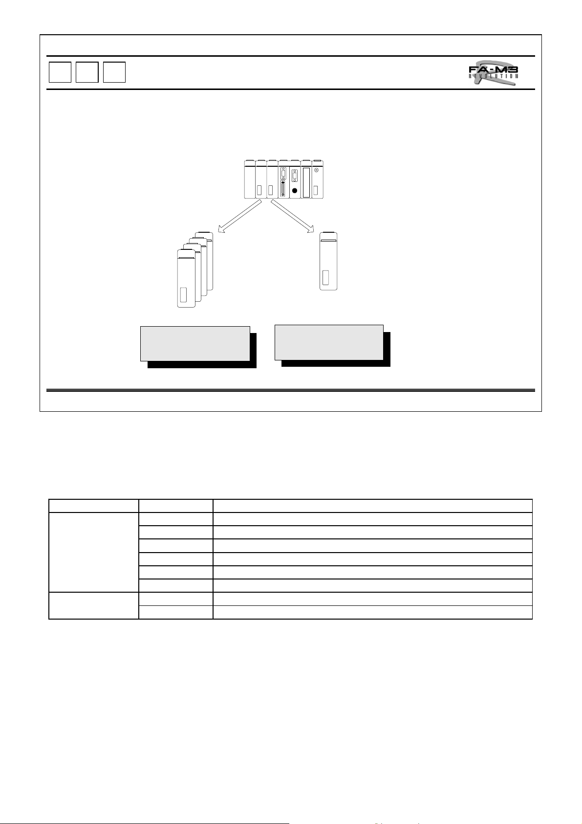
Multiple CPUs
•Use any programming language you like.
•Use the optimum language for your applicatio ns.
•Combine languages freely .
Up to 4 CPU modules can be combined.
Ultra-high-speed
processing
Sequence CPU BASIC CPU
Up to 4 ladder programs
can be run, allowing task
to be shared.
• Mechanical engineers may prefer a ladder diagram, while production engineers may prefer BASIC.
Æ
The FA-M3 R allows the programming language to be chosen freely.
• Sequence CPUs are good for tasks requiring high-speed proc essing, a BASIC CPU for floating-point and
character calculations.
Æ
You can select CPUs to meet your application requirements.
Real-time BASIC programs
can be run.
Communication and
text processing
(character handling)
* Only one BASIC CPU mod ule can be installed per controller.
*
Module Model Specifications
Sequence CPU F3S P 21-0N
modul e F3SP28-3N
F3SP38-6N
F3SP53-4H
F3SP58-6H
F3FP36-3N
BA SI C CPU F3BP20-0N
modul e F3BP30-0N
• Any CPU can directly access I/O modules.
• Different types of CPU modules can exchange data with each other.
•Without additional module(s), the above mentioned CPU module can achieve function of
a controller.
Str uc tured ladder languge, 10K steps, 0. 18 µs/basic instr uc tion
Object ladder language 30K steps, 0.045 µs/basic instruction
Object ladder language 120K steps, 0.045 µs/basic instruct ion
Object ladder language 56K steps, 0.0175 µs/basic instruction
Object ladder language 120K steps, 0.0175 µs/basic instruct ion
Ladder and SF C language, 40K steps, 0. 09 µs/c ont ac t or c oil instruct ion
YM-BASI C/ FA language, 120KB
YM -B ASI C/ F A language, 510KB
TI 34M6A01-01E
7
Page 12
P
P
L
L
C
C
Sequence CPU Modules
Larger Program Capacity, Device Capacity and
Variety of Instructions than for High- end PLCs
Seven modules to meet various needs.
Number of i nputs / output s 2,048 2,048 4,096 8,192, 4,096 8,192 4,096
Number ofBasic 252533333333 8
instructions Application 227 227 312 312 312 312 59
Processing
speed per
instruction
Program capacit y (st eps ) 5K 10K 30K 120K 56K 120K 40K*
Number of program blocks 32 32 1,024 1,024 1,024 1,024 1,024**
Devices Timers*** 512 512 2,048 3,072 2,048 3,072 2,048
Relays Internal 4,096 4,096 16,384 32,768 16,384 32,768 8,192
Registers Data 5,120 5,120 16,384 32,768 16,384 32,768 5,120
Item
Basi c (µs) 0.18–0.36 0.18–0.36 0.045–0.18 0.045–0.18 0.0175– 0.07 0.0175– 0.07 0.09–0.18
Application
(µs)
Counters*** 512 512 2,048 3,072 2,048 3,072 2,048
Shared — 2,048 2,048 2,048 2,048 2,048 4,096
Link 2,048 2,048 8,192 16,384 8,192 16,384 8,192
Special 2,048 2,048 9,884 9,884 9,884 9,884 9,984
File — — 32,768 262,144 32,768 262,144 27,648
Link 2,048 2,048 8,192 16,384 8,192 16,384 8,192
Special 512 512 1,024 1,024 1,024 1,024 512
Index 32 32 256 256 256 256 —
Shared — 1,024 1,024 1,024 1,024 1,024 4,096
F3SP05 F3SP21 F3SP28 F3SP38 F3SP53 F3SP58 F3FP36
Min. 0. 36 Min. 0. 36 Min. 0.18 Min. 0.18 Min. 0.07 Min. 0.07 Min. 0.18
* Capacity in steps of lad der program
** Capacity in steps of sequence function chart (SFC)
*** T ot a l numb er of tim er s a nd co u nter s
F3SP05-0P, F 3SP21- 0N, F3SP 28 -3N, F 3 SP38-6 N, F3SP5 3- 4 H, F3SP58 -6H an d
F3FP36-3N Sequence CPU Modules
• High-speed execution of instructions easily handles high-speed processing and response.
(Scan time of 1 ms for a 20K step program when us ing an F3SP53 or F3SP58)
• Sensor control function enables quick scan (input Æ program execution Æ output)
besides normal scan . This allows to have stable input/output response of 400 µs (200 µs
x 2). (when using an F3SP28, F3SP38, F3SP53 or F3SP58).
• Inheriting the structured programming, object ladder programmingis adopted as a
dramatically upgraded programming language that facilitates program development and
modification (for the F3SP28, F3SP38, F3SP53 or F3SP58).
• User-defined macro instructions can be created and registered.
• Enriched functions, such as forced set/reset that are not affected by the results of
program computations as well as a scan operati on, fac ilit ate progra m debugg ing and
modification.
• The PROGRAMMER port (connection port for programming tool) supports a personal
computer link, allowing linkage to upper-level computers and display units without a
personal computer link module (at maximum baud rate of 115K bps for the F3SP28,
F3SP38, F3SP53 or F3SP58).
• Programs and data can be stored in an optional ROM pack, which is useful when
performing program replacement and making many copies of the same program on site.
• Protect function is provided to prevent programs from being read and copied by
unauthorized persons.
RDY
RUN
ALM
ERR
SP53-4H
CPU
RDY
RUN
ALM
ERR
SP58-6H
CPU
PROGR
AMMER
PROGR
PROGRAMMER
AMMER
PROGRAMME R
F3SP53-4H
F3SP58-6H
RDY
RUN
ALM
ERR
SP21-0N
CPU
RDY
RUN
ALM
ERR
SP28-3N
CPU
RDY
RUN
ALM
ERR
SP38-6N
RDY
RUN
ALM
PROGRAMMER
ERR
FP36-3N
PROGRAMMER
PROGRAMMER
PROGRAMMER
F3SP21-0N
F3SP28-3N
F3SP38-6N
F3FP36-3N
CPU
CPU
Note: The F3FP36-3N is used for both SFC and ladder pro grams (ladder program s only is availabl e), and supports
neither index modific ation, scan operation, person al computer link, user log, ROM pack nor program security.
TI 34M6A01-01E
8
Page 13
P
P
L
L
C
C
BASIC CPU Modules
YM-BASIC/FA, th e world's fastest BASIC
•
Incorporates YM-BASIC/FA, a BASIC language for real-time control used in proven Yokogawa
YEWMAC500 computer for factory automation.
•
Realizes a BASIC program-based controller (no need for a sequence CPU module).
•
Can directly access inputs and outputs.
Direct I/O access without a sequence CPU enables field data to be read and written at high speed.
(16 I/O points can be accessed within 5.2 ms.)
F3BP20-0N
F3BP30-0N
TOP77RT/TOP72S
FA-M3 R
•
Ideal for high-level computations
•
Simplifies character and array computations.
•
Dedicated interpreter realizes high-speed
processing.
Real-time control of field
F3BP20-0N and F3BP30-0N BASIC Modules
• Useful for communication tasks or high-level computations that are not easily controlled by
a ladder program.
• Can configure as a BASIC controller since a BASIC CPU module alone can be used
without a sequence CPU module.
• When installed in slots 2 to 4, BASIC CPU modules work as add-on BASIC CPU modules
for a sequence CPU module.
• Can directly access input and output modules.
• Can exchange data with ladder programs and synchronize with ladder programs by using
events.
• Allows structured programming using subprograms.
• Can access common data with a personal computer link module (can also connect a
display unit and access data via Ethernet or modem).
• The PROGRAMMER port (connection port for programming tool) provided with each
BASIC CPU module allows programming for each CPU.
RDY
RUN
ALM
ERR
BP20-0N
CPU
RDY
RUN
ALM
ERR
BP30-0N
PROGRAMMER
PROGRAMMER
CPU
• Programs can be developed and debugged on a personal computer.
• By installing an optional ROM pack, programs and common data can be saved and the
programs in the ROM pack can be run. The ROM pack is useful when performing
program replacement and making many copies of the same program on site.
TI 34M6A01-01E
F3BP20-0N
F3BP30-0N
9
Page 14
P
P
L
L
C
C
Easy Real-time Processing with BASIC
A statement to start an interrupt routine needs only one line.
F3BP20-0N and F3BP30-0N
FA-M3 R
F3BP20-0N
F3BP30-0N
YM-BASIC/FA
Barcode Remote ID
100 ON INT 2 , 5 GOSUB WARI@
110 !
120 LOOP@
130
.
Main routine
.
.
140 GOTO LOOP@
150 !
160 WARI@
170 !
180 ENTER xxxxx
190 OUTPUT xxxxx
200 RETURN
210 !
220 STOP
230 END
YM-BASIC/FA, real-time BASIC
Data input
Data output
Interrupt st atement
Interrupt routine
Barcode reader
• On-line real-time processing
- Supports extensive interrupt methods to enable immediate response of a BASIC program to external events.
- Facilitates development of on-line real-time programs.
• Modular program structure
- Can use subprograms.
- Variables, line numbers and labels in the main and individual subprograms independently, thus it simplifies
development and program maintenance, and improving program reusability.
- The main program and subprograms can be developed separately, and assembled together by using the
APPEND command later.
• Combination with sequence programs
- Variables used in a BASIC program can be combined with shared registers by a common variable
statement, thus it facilitates data exchange with sequence CPU module. Synchronization with sequence
CPU modules can also be achieved by using SIGNAL, ON SEQEVT, ENTER and OUTPUT statements.
- Device values in CPU modules can be read and written by using ENTER and OUTPUT statements.
• I/O support
- Can access various communication modules such as serial communication modules, various digital I/O
modules, and various analog I/O modules by using ENTER statements for input and OUTPUT statements
for output.
TI 34M6A01-01E
10
Page 15
P
P
L
L
C
C
Ladder Programming Tool Designed for Engineers
Ultimate pr og ram reusability.
WideField dramatically reduces Total Cost of Ownership
by customization of each machine.
FA-M3 Programming Tool WideField
Object ladder Enriched help
Program Component Remote OME*
Index view System log*
Collective change of I/O positions User log*
Logical design by tag name Sampling traces*
Group tag name Ethernet connection*
Advantages of Windows environment Modem connection*
Flexible operability
Sophisticat ed debugging functions
* See the respective pages of these excellent maintenance functions for det ails.
System Design
Program Design
Programming
Debugging
Running
Maintenance*
WideField great ly
reduces the time
required for these
processes.
FA-M3 Programming Tool WideField (SF610-E3W)
WideField solves all issues facing user program development. It offers extensive features for greatly
increasing the efficiency of program development, such as the clarification of the component structure of
programs, improved visibility, under the familiar Windows environment.
z
Product concept:
• Customized program design
• Operability
• Reusability
• Link with other applications
• Visibility
• Ease of debugging and maintenance
• Concurrent development by multiple engineers
• Improved software quality
• Shorter development period
z
WideField is ready to go simply by installing it in your PC.
z
WideField can be run under Windows 95, Windows 98 or Windows NT 4.0.
TI 34M6A01-01E
11
Page 16
P
P
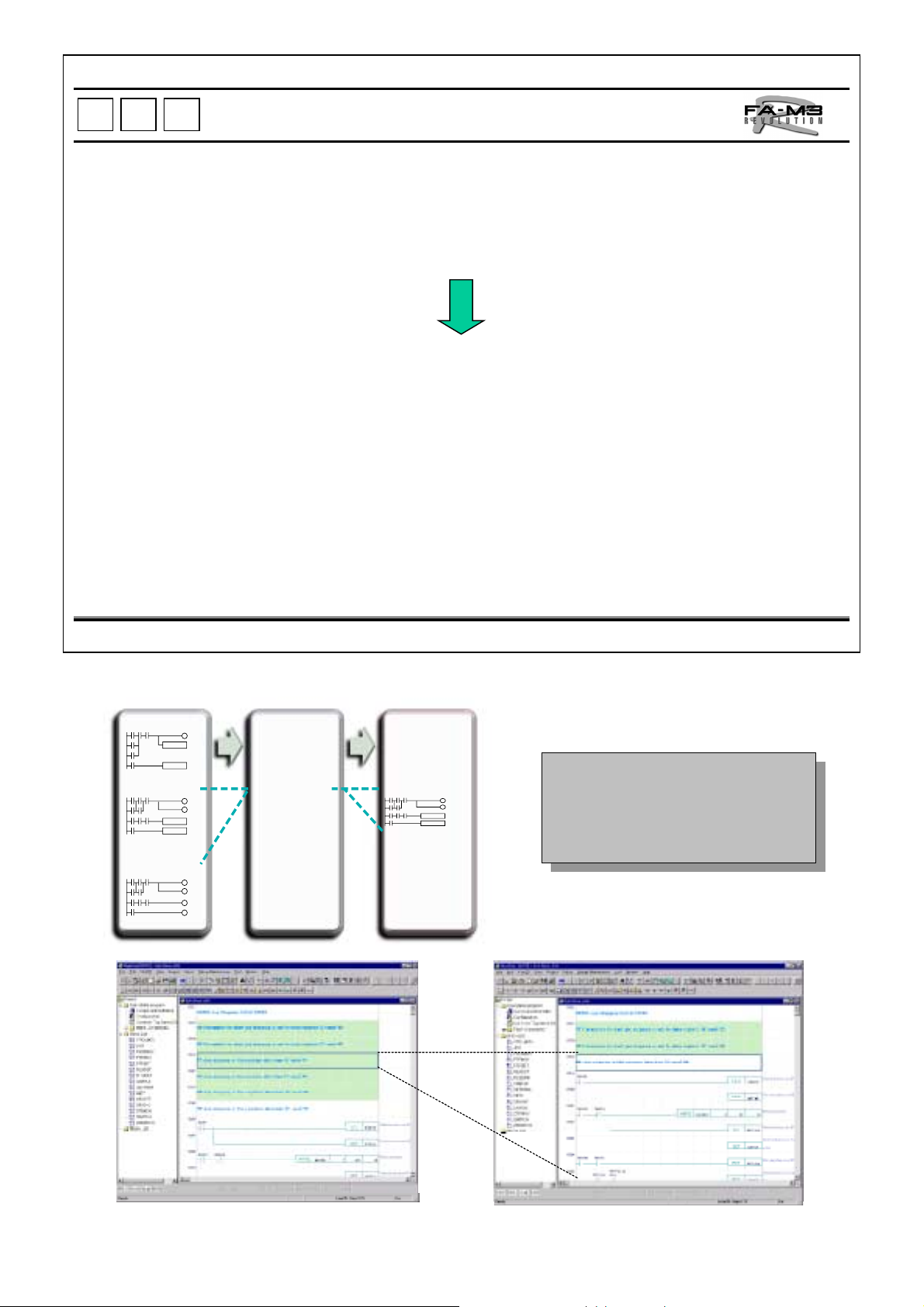
The FA-M3 Programming Tool WideField is a revolutionary application for programming object
An object ladder is a new concept of developing programs. The object in which a piece of program
An object ladder is highly reusable. When customizing an existing machine control program for a
C
L
C
L
ladder succeeding to structured ladder programming and created with new concept.
and the related devices are assembled for each functional unit called a block. The blocks are then
assembled together to form the entire ladder program. Each block can thus be functionally
independent, which improves productivity and program maintainability compared to structured
programming*.
particular user, the details of each block need not be checked; blocks are simply added or replaced.
Object Ladder
1990
Structured
programming
Conventional ladder
programming
2000
Object ladder
programming
*
Structured programming.
Yokogawa Electric Corporation in 1989, in which an increasingly
complexed ladder program is divided into parts for individual functional
units so that developers can easily understan d t he program framework,
and improved productivity and program maintainability. As these
advantages became recognized in the 1990's, structured programming
grew rapidly. Other PLC manufacturers rolled out product s based on the
same concept, and structured program m ing is now t he de facto standard
in PLCs.
A programming method proposed by
TI 34M6A01-01E
12
Page 17
P
P
L
L
C
C
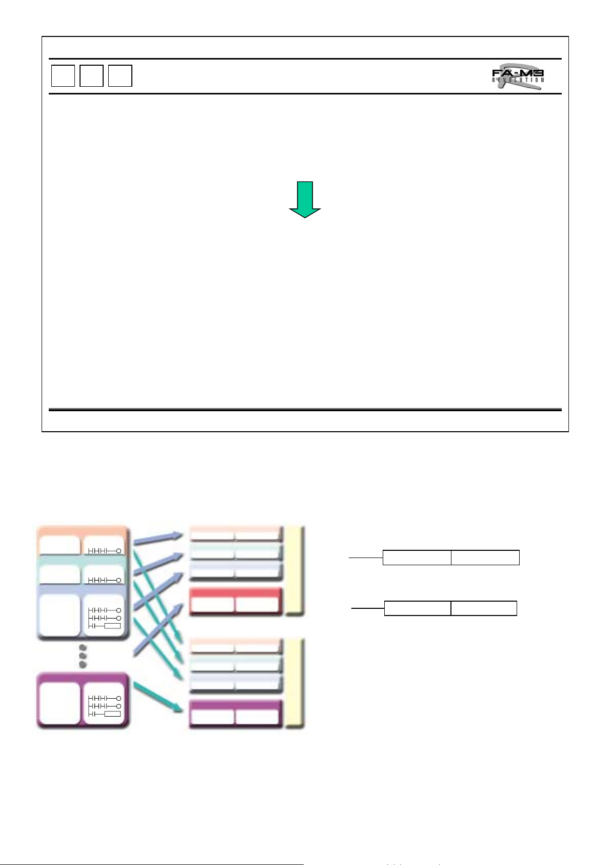
Program Component
Independence of Blocks and Macros for Enhancing Drastical Reusabi lity.
Blocks and macros are pieces of program and use common devices as their data. Thus,
devices need to be assigned uniquely not to doubly used in different blocks and macros.
By using the concept of local devices in each block and macro, devices can be handled
independently in each block and macro.
Different macros and blocks can have a local device having the same name since
different physical addresses will be assigned to those local devices, thus device conflict
can be avoided
.
Programs and local devices can be handled as sets so that they can be reused easily as
parts.
Basic Blocks
Block A
Local
devices
Block B
Local
devices
Block C
Local
devices
-Reylay
-Register
-Timer
-Counter
Block Z
Local
devices
-Reylay
-Register
-Timer
-Counter
Program
Program
Program
Program
Standard configuration
Block A
Local devices
Block B
Local devices
Block C
Local devices
Block D
Local
devices
Optional
Block A
Local devices
Block B
Local devices
Block C
Local devices
Block Z
Local
devices
Program
Program
Program
Program
configuration
Program
Program
Program
Program
Address Indication
z
Global devices
Local device
Global device
Global devices
MOV /D1
MOV D1
• Local devices and global devices can be used
as different devices.
• When reusing a block, device addresses need
not to be changed.
• When local devices need to be added in a block,
no change to other blocks is needed.
TI 34M6A01-01E
13
Page 18
P
P
L
L
C
C
Index View
Increased Efficiency of Reuse with Improved Visibility.
A ladder program is coded as a long strip of diagram, which makes it difficult to grasp the
overall flow.
The entire program structure can be grasped.
You can hide and show each circuit block under the circuit comment (just like expanding
and collapsing the tree) to grasp the entire program structure and go to the corresponding
parts.
Programs written long ago or written by other engineer can be easily modified.
Index View
♦Supply of materials
♦Preparatory neating
♦Flacks coating
♦Formalting
♦Idling
•
•
•
♦Supply of materials
♦
Preparatory neating
♦Flacks coating
♦Coating
♦Fixing heating
♦Cleaning
♦Cooting
♦Unloading
•
•
•
♦Diagnosis
♦Power off
♦Formalting
♦Idring
•
•
•
♦Supply of materials
♦Preparatory neating
♦Flacks coating
♦Coating
♦Fixing heating
♦Cleaning
♦Cooting
♦Unloading
♦Diagnosis
♦Power off
Debugging after grasping
Debugging after grasping
the overall flow
the overall flow
Collapsed View of Circuit Expanded View of Circuit
TI 34M6A01-01E
14
Page 19

P
P
L
L
C
C
Collective Change of I/O P osi ti on s
Whenever the I/O m od ule allocation is changed,
the I/O addresses in the program can be changed instantly.
Before change
After change
Addition of
Addition of
I/O Modules
I/O Modules
Before change
After change
Deletion of
Deletion of
I/O Modules
I/O Modules
z When a standard machine control program is customized and I/O modules need to
be added or their position changed, the I/O addresses in the program can be
collectively changed accordingl y for each slot.
TI 34M6A01-01E
15
Page 20

P
P
C
L
C
L
A name suggesting the corresponding action can be assigned to each device to increase
maintainability.
Arbitrary names for individual devices can be used in the programming before the terminal
assignment is decided. The ability to separately determine the logical design and physical
design (i.e., program design and terminal assignment) greatly reduces the engineering
period.
Wiring changes can be accomplished be changing the tag definitions.
Use of tag names helps standardize circuits and enables programs to be reused with ease.
Logical Design by Tag Name
X00021
I00015
X00023
z Tag names can be set easily (see the figure below right);
however, even if the tag names have not yet been set ladder
diagrams can be edited using tag names.
Even when the terminal assignment has not yet been
Æ
decided, programs can be developed using signal
names.
z Tag names should be up to 8 characters long and begin with 2
alphanumeric characters.
X00022 I00015
Y00056
Conventional PLCs require
terminal addresses.
START
LOCK
SWITCH
The FA-M3 R allows you to write in
logical addresses (tag names).
KEEP LOCK
ABOUT
TI 34M6A01-01E
16
Page 21

P
P
L
L
C
C
Group Tag Name
Sets of names can be named to enable data sets to be managed under group names
System Configuration
Multi-axis positioning control
C
C
H
H
2
1
CH1
• Intuitive understanding by group presentation
• Intuitive understanding by group presentation
• Efficient programming by group handling of data
• Efficient programming by group handling of data
CH2
M M M M
C
C
H
H
3
3
CH3
CH8
Group Name Settings
Group name
PCH1
Signal Name Address
START Y00233
STOP Y00234
ERROR X00201
PAUSE Y00235
Programming
AUTO1
NO_ERR Pch1.START
AUTO2 NO_ERR READY2
AUTO3
READY1
Pch2.START
START Pch1
TI 34M6A01-01E
17
Page 22

P
P
L
L
C
C
Advantages of Windows Environment
Effortless da ta exchange with Windows-based applications.
Support for versatile Windows technologies such as OLE.
Tag name definitions set on a Microsoft Excel sheet can be imported into
WideField.
Data in WideField, such as a ladder diagram, can be utilized for the As Built
Drawings.
A Engineering Document can be easily created.
Note: The As Buil t Drawings and Engineering Document indicat e documents prepared using a Windows-
based application.
Practical use of Microsoft Excel
Tag name definitions can be copied and pasted not only
between Excel and WideField but also to engineering
documents.
Signal
Definitions
MS-Excel
As Built Drawings and other
engineering documents can be
easily prepared as Microsoft
Word documents using copy and
paste.
TI 34M6A01-01E
18
Page 23

P
P
L
L
C
C
Flexible Operability
Ladder diagrams can be modified like editing a document with a word processor.
Programming problems are minimized and operability maximized.
Program modification and monitoring can be done simultaneously by
opening multiple windows.
Both mouse and key operations are supported.
Connection lines can be dawn and deleted by dragging.
Shortcut menus displayed by right-clicking provide quick access to
commands valid for that screen region or selection.
A range of a ladder diagram can be copied and pasted between different
programs.
From a list of search results, a desired point can be retrieved.
All instructions can be entered by typing characters, and automatically
converted to the corresponding device on the screen.
You can select a device type from the I/O configuration and monitor the
statuses of the correspondin g devices.
File structure can
be viewed while
programming.
Intuitive operations with
buttons having symbolic
labels.
Comments and
diagram portions can
be colored differently
for visual
identification.
TI 34M6A01-01E
Example of Window Display
CPU running status can
be checked at all times.
19
Page 24

P
P
L
L
C
C
Sophisticate d Debugging Functions
Ladder diagrams can be modified while they are running.
User-oriented debugging functions assist program development and modification.
The log of CPU-detected errors can be viewed as the System Log, and the
trend of the system running status can be managed as the User Log.
Multiple parts of a diagram can be changed at once and modified parts can
be reverted at once, all while online.
Monitoring and debugging can be done via multiple personal computers
concurrently.
Fast scrolling quickly brings onto the screen in which the part of the diagram
you want to monitor.
Monitored data values can be displayed as deci m al, hexadecimal, binary,
character or floating-point values as you choose.
Security protection can be set for each program.
Choosing a device type, and
monitoring, setting and resetting
device values.
TI 34M6A01-01E
Example of Device Monitor
20
Page 25

P
P
L
L
C
C
Enriched Help
A description, operands and examples of action are shown for each instruction.
The appropriate help for each situation can be called.
Details on how to use an instruction and its act i on can be referenced.
An outline of a function and how to use it can be referen ced.
Potential causes and countermeasures for an error can be referenced.
Items can be looked up by entering a key word.
The help for an instruction can be called by choo sing the instruction from a
list of instructions.
Easy key operations
in the field.
A description, operands and
examples of action are shown for an
instruction.
Example of Help
CPU running
status can be
checked at all
times.
TI 34M6A01-01E
21
Page 26

P
P
L
L
C
C
BASIC Programming Too l M3 for Windows
Convenient BASIC program development under Windows environment.
Features:
Runs under Windows 95, Windows 98 or Windows NT.
Sophisticated debugging functions:
•
On-line program modification
•
Variable data trace
•
Break actions
•
Step run
CPU self-diagnostics:
•
•
Ref Check of various CPU settings and shared data
settings erence to CPU error log
Help:
•
Online help for functions, statements and commands
•
Help for errors and countermeasures
BASIC Programming Tool M3 for Windows (SF560)
BASIC Programming Tool M3 for Windows (SF560) is a Windows-based application for programming and
debugging applications for the BASIC CPU modules (F3BP20/30) as well as for setting up those CPU modules.
SF560 can perform all engineering, including programming, debugging and maintenance.
TI 34M6A01-01E
22
Page 27

P
P
C
L
C
L
Supports remote OME* via Ethernet or Public Phone Line with modem.
Allows the operation status to be checked and failures to be analyzed with
reference to the Error Log and User Log.
Allows complex failures and rare failures to be analyzed using the sampling t race
function.
Allows modules to be replaced easily even when installed inside a panel or
machine because they are detachable from the front.
Reduces maintenance and spare parts because part s can be stocked in common
for all systems regardless of scale. Maintenance parts no longer need to be
stocked separately for each system scale or model.
Outstanding Maintenance Support Function s
* Acronym of remote Operation Maintenance and Engineering proposed by Yokogawa Electric Corporation.
z
The memory backup batteries for all CPU modules are maintenance-free and have a shelflife of at least 10 years and a service life of at least 30 years under normal operating conditions
(ambient temperature of 30, and operating time of 12 hours/day)
TI 34M6A01-01E
23
Page 28

P
P
C
L
C
L
The FA-M3 R supports remote equipment maintenance, called "Remote OME. "
Remote OME involves performing the following remotely:
z O
peration: Operation and monitoring
z
M
aintenance: Troubleshooting
z E
ngineering: Program modification and debugging
Remote OME is achieved:
(1) Over a local area network via Ethernet, whereby OME requests are connected using a readily
available dial-up router to a public phone line
(2) Over public phone lines via a modem connected to the Programming port
Remote OME
z
For an FA-M3 R incorporated in a system, the following can be done from a personal computer at a distant
place:
• Machine maintenance and inspections using the device monitoring and diagnostics functions
• Check of machine operating statuses by monitoring the FA-M3 R's devices online, and machine
operation test by changing the device values
• Troubleshooting and failure analyses for machine using the FA-M3 R's diagnostics functions, namely,
such as to the error log, user log and sampling traces
• Improvement of machine operation by adding, modifying and debugging a ladder diagram.
z
There are two methods of remote OME:
• Via Ethernet ( remote maintenance camera is available)
• Via public telephone lines
TI 34M6A01-01E
24
Page 29

P
P
L
L
C
C
Remote OME via Ethernet
The FA-M3 R is the world's first* PLC that supports remote maintenance of multiple pieces of
machines installed in distant locations, via Ethernet. Using a remote maintenance camera,
remote maintenance can be performed while actually monitoring the equipment.
The following can be performed remotely with the standard features of WideField:
z Editing/loading/saving programs, monitoring ladder diagrams, monitoring devices,
monitoring operation statuses and reading various data. The personal computer
link feature can also be used.
z System log, user log and sampling traces that fully support remote OME
Ethernet
Public telephone line / ISDN (Integrated Services Digital Network)
Ethernet
z
Remote OME via Ethernet
• By connecting all the FA-M3 R controllers
incorporated in equipment at a plant, via
Ethernet all the machine statuses can be
viewed from a personal computer in an
office or control room.
• All functions of WideField can be used for
the FA-M3 R controllers remotely.
• Monitoring and data modification of one
FA-M3 R controller can be performed
simultaneously from multiple personal
computers via Ethernet.
EthernetEthernet
* Programs cannot be developed or modified with any
other manufacturer's PLC. An F3LE01-5T Ethernet
interface module and a personal computer r unning
Windows 95 or Windows NT are required.
Electrical Equipment Room /
Factory
Ethernet
FA-M3 R
Ethernet
Interface Module
Ethernet
D1 1234
D2 5678
D5 1927
Ethernet
Office
D1 1234
D2 5678
D3 9876
D4 1357
However, WideField cannot run
simultaneously on two or more
computers on the network.
TI 34M6A01-01E
Mechanical Equipment Room /
Factory
Camera
Ethernet
Machine A Machine B
D1 1234
D2 5678
D5 1927
Control Room /
Maintenance Facility
25
Page 30

z
Remote OME via Ethernet and Dial-up Router
Factory / Plant Engineering Dept. / Headquarters
Operating status
monitoring, program
modofication, program
start/stop, and error log
reading
F3LE0
FA-M3 R
1-5T
Remote maintenance
camera
FA-M3 RFA-M3 R
Ethernet
Dial-up router
Public
phone
Line
Windows-based
Dial-up router
PC
DOS-based
PC
Ethernet
• Remote OME is made available in various facilities at plants via Ethernet. Moreover, by using a public
phone line with dial-up routers as shown in the figure above, remote OME of equipment from
headquarters is possible through the FA-M3 R controllers connected to the Ethernet network inside
respective plants, even if they are located abroad.
z
Remote Maintenance Camera*
• Ethernet is fast enough to transmit large amounts of data such as images and sounds. By installing a
network camera and sound interface, you can perform remote OME while monitoring live images of the
equipment status captured by the camera.
Features of the remote maintenance camera:
• Nothing else needed for connection to Ethernet, as
web sever capabilities are built in.
• The captured image can be viewed using general
browsers including Netscape Navigator and Internet
Explorer.
• Manufactured by Axis Communications.
Image Viewing via Ethernet
Network Camera for
Remote Maintenance
AXIS 200 + Camera Server
The AXIS 200 full-color, digital network
camera and the Camera Server from
AXIS Communications bring you a realtime view of the remote location.
TI 34M6A01-01E
26
Page 31

P
P
L
L
C
C
Remote OME Using Commercially-available Modem
An FA-M3 R installed in a distant location can be
maintain ed via a public te lephone line.
The following can be performed remotely with the standard features of WideField:
Editing/loading/saving programs, monitoring ladder diagrams, monitoring devices, monitoring operation
statuses, viewing system log, reading various data, and more.
Programming, debugging,
and other data
reading using WideField
Modem
Modem
Public phone line
For connection, you need to do the following:
z
Modem for the personal computer
• Set the communications protocol (baud rate, data length, etc.) using AT commands.
z
FA-M3 programming Tool WideField.
• Set up the modem connection:
Æ
Tool
z
FA-M3 R
• In the configuration settings, set the CPU communication port as follows:
- 9600 bps without parity check
- Use the personal computer link
The program in which the above configuration is set up needs to be downloaded in advance. When downloading
a program via a public telephone line, make sure that the program configuration is set as above
z
Modem for the FA-M3 R
• Switch on the automatic terminal mode.
• Set the communications protocol using
AT commands.
Setup Environment ÆSetup Communication.
.
TI 34M6A01-01E
27
Page 32

P
P
L
L
C
C
System Log
Status changes, failures and errors during operation of
an FA-M3 R can be re corded.
z The system log lists the date, time and message of each event to allow you to grasp the past
operation log and analyze changes in the system status and the results of program failures.
z The information displayed as the system log can also be printed and saved to a file, which can
then be opened and printed later.
Date and Time Message Detail Block Instruction/
Code Name Slot No.
11/07/1999 15:12:15 Startup Completed 01-00
10/29/1999 15:11:03 Power Off 03-00
10/29/1999 15:10:50 I/O Check Error 24-01 ACT3 00013N
10/29/1999 15:09:20 I/O Check Error 24-01 ACT3 00013N
10/29/1999 15:08:05 I/O Check Error 24-01 ACT3 00013N
10/29/1999 15:07:55 I/O Check Error 24-01 ACT3 00013N
10/29/1999 15:07:20 I/O Check Error 24-01 ACT3 00013N
10/29/1999 15:06:22 I/O Check Error 24-01 ACT3 00013N
10/29/1999 15:05:33 I/O Check Error 24-01 ACT3 00013N
10/29/1999 14:04:45 Subunit Communication Error 06-00 SLOT=1607
10/29/1999 12:43:51 I/O Check Error 24-02 READST 00012N
z
Display
System status changes (power-on/off), failures and
errors occurring in the past are displayed in
chronological order with the latest event at the top.
A maximum of 70 to 150 of such events (the number
depends on the contents of the event data) can be
stored. When the stored event data reaches the
storage capacity, the latest event data overwrites the
oldest event data.
z
Printout
The displayed log can be printed in the same format.
z
Storage and retrieval
The displayed log can be saved to a file and the
saved file can be opened.
Note: The system log can be monitored from a
remote location via Ethernet.
Example of System Log
TI 34M6A01-01E
28
Page 33

P
P
L
L
C
C
User log
Alarms, events and errors for equipment and
machines (controlled by an FA-M3 R) occurring during operation can be logged.
z In addition to the system log, user-defined messages can be recorded (for up to 64 messages per CPU)
as the user log.
z The user log lists the date, time and message of each event to allow you to grasp the past operation log
and analyze changes in the system status and the results of improper equipment/machine operations.
z The information displayed as the user log can also be printed and saved to a file, which can then be
opened and printed later.
Date and Time Message No./Para met er /Mes s age Te xt
09/28/1999 11:59:09 main= 18 sub= 1 Heater Failure
09/28/1999 10:34:48 main= 14 sub= 1 Run Out Of Material
09/28/1999 08:30:32 main= 1 sub= 1 Machine Start
09/27/1999 17:34:27 main= 2 sub= 1 Machine Stop
09/27/1999 17:05:40 main= 6 sub= 1 Lot End
09/27/1999 17:00:10 main= 4 sub= 1 Product Departure
09/27/1999 16:05:32 main= 40 sub= 5 Alarm On
09/27/1999 15:59:58 main= 12 sub= 1 Limiter Off
09/27/1999 15:57:24 main= 11 sub= 1 Limiter On
09/27/1999 08:55:32 main= 3 sub= 1 Product Entry
09/27/1999 08:45:40 main= 5 sub= 1 Lot End
09/27/1999 08:30:51 main= 1 sub= 1 Machine Start
Define messages in the dialog box shown right, and carry out
ULOG instructions in the ladder diagram. Then, the specified main
code, subcode, and the time and date of occurrence for each will be
stored in the user log data storage area. You can also send user
log information to other equipment by using the ULOGR instruction.
z
Other related instructions and devices
•
UCLR instruction: Clears the user log
•
Z105 register: Special register for the number of
user log messages to be stored
z
Display
User log messages occurring in the past are
displayed in chronological order with the latest event
at the top.
Up to 64 messages corresponding to the main codes
can be stored per CPU. W hen the stored message
data reaches the storage capacity, the latest message
data overwrites the oldest message data.
z
Printout
The displayed log can be printed in the same format.
z
Storage and retrieval
The displayed log can be saved to a file and the saved
file can be opened.
.
Note: The user log can be m oni tored from a remote location via
Ethernet or a public phone line.
TI 34M6A01-01E
29
Page 34

P
P
z You can trace device values while running a program.
z You can also record device values before the trigger condition is established.
z You can use sampling traces not only while debugging but also during operation for troubleshooting
z Use of the sampling trace function does not affect the scan time.
z Sampling traces are very useful for capturing phenomena that seldom occur, such as once a week or
C
L
C
L
and failure analyses (no other manufacturer's PLC provides this function
month.
Sampling Traces
).
Specifications
Number of sampling points: 16 relays / 4
registers.
Sampling timing:
Whenever a TRC instruction i s carried out
•
At specified intervals (10 to 2000 ms)
•
• At the end of every 1 to 1000 scan
intervals
Number of traces : 1024
Trigger condit ion:
Specified relay
•
Data matching f or the specif ied device
•
By configuring the trigger condition with the ladder program, you
can attain traces of the values of the desired devices when
complicated conditions including status transitions are met.
Sampling traces can be attained without affecting the scan time of
the ladder program.
Non-conformities occurring at irregular times can be
Æ
detected.
There are two setting methods:
z
Add the setting in the configuration of the user program.
•
Make settings at any time you want during operation.
•
Display
z
Sampling traces can be displayed in a time chart format
together with the relay statuses and register values
sampled.
Settings in configuration prior to runtim e
z
You can make sampling trace settings previously in the
configuration so that sampling traces are obtained during
normal operation.
* The sampling trace function is available in the SP25 and SP35.
Making Sampling Trace Settings
Settings on demand
z
You can make sampling trace settings at any time you
want.
Storage and retrieval
z
The obtained sampling traces can be saved to a file and the
saved file can be opened.
TI 34M6A01-01E
30
Page 35

P
P
L
L
C
C
High-speed Conversion, High Precision and High Noise Tolerance
Combined with a high-speed CPU module, high-speed analog input and output control system
can be built.
(1) Analog Input Modules
F3AD04-0N: 4 analog inputs
F3AD08-1N: 8 analog inputs
• Input signal range: -10 to 10 V DC, 0 to 5 V DC, 1 to 5 V DC
• Accuracy : 0.2% of full scan (at 23 ºC ± 2 ºC) or 0.5% of full scan (at 0 to 55ºC)
• Conversion period: 1 ms/channel
• Other features: Filtering, scaling and channel skip functions as well as a noise-resistant conversion
system
(2) Analog Output Modules
F3DA02-0N: 2 analog outputs
F3DA04-1N: 4 analog outputs
F3DA08-5N: 8 analog outputs (voltage output only)
• Output signal range: -10 to 10 V DC or 4 to 20 mA DC
• Accuracy : 0.2% of full scan (at 23 ºC ± 2 ºC) or 0.5% of full scan (at 0 to 55ºC)
• Conversion period: 2 ms (fixed) for F3DA02-0N, 4 ms (fixed) for F3DA04-1N and F3DA08-5N
• Other features: Output upon error occurrence
Analog Input/Outp ut M od ule s
F3DA02-0N: Holds the output levels.
F3DA04-1N: Holds the output le vels or sets to t he preset level , as specified.
F3DA08-5N: Holds the output le vels or sets to t he preset level , as specified.
For all five types of modules, the module's internal circuit is isolated by photocouplers from the field.
z Channe l skip
In analog input modules, A/D conversion for unused channels can be stopped, and data is not updated
for a channel specified to be skipped. This speeds up t he conversion period for all channels.
The conversion period is expressed as: 1 ms × num ber of channels used
RDY
ALM
AD04-0N ADC
+
IN1
-
SHIELD
+
IN2
-
+
IN3
-
SHIELD
+
IN4
-
RDY
ALM
AD08-1N ADC
+
IN1
+
IN2
+
IN3
+
IN4
-
SHIELD
AG
+
IN5
+
IN6
+
IN7
+
IN8
-
DA02-0N
V+
V-
OUT1
I+
I-
V+
V-
OUT2
I+
I-
+
-
RDY
ALM
DAC
RDY
ALM
DA04-1N DAC
+
V
-
OUT1
+
V
-
+
V
-
OUT2
+
V
-
+
V
-
OUT3
+
V
-
+
V
-
OUT4
+
V
-
RDY
ALM
DA08-5N ADC
+
OUT1
+
OUT2
+
OUT3
+
OUT4
-
OUT5
+
+
OUT6
+
OUT7
+
OUT8
-
TI 34M6A01-01E
F3AD04-0N F3AD08-1N F3DA02-0N F3DA04-1N F3DA08-5N
31
Page 36

P
P
L
L
C
C
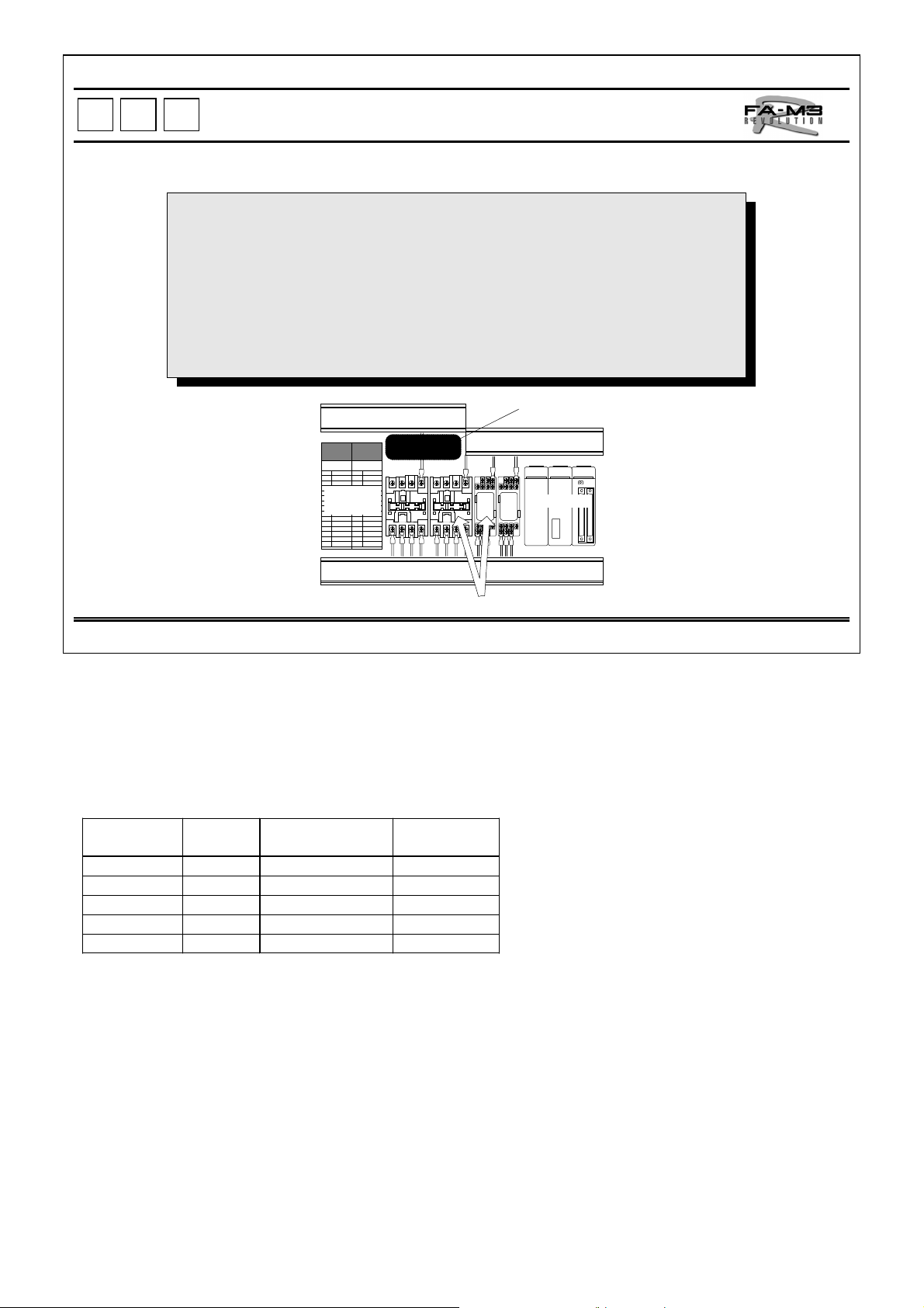
Temperature Control Modules
Four Temperature Controllers in One Compact FA-M 3 R Module
Wide range of temperature controller module lineups for all types of inputs and outputs.
Selectable speed of control span according to the application requirement: 500 ms/4 channels,
250 ms/2 channels, 125 ms/channel
Auto/manual mode switching useful for sequence maintenance at machine startup.
PID control for heating/cooling
Overshoot protection feature
Cascade control using multiple channels
Input Type Output Type
Modu le
name
Temperature
control and
monitoring
PID control F3CV04 -1N
Model
F3CT04
F3CR04
-0N
-1N
-0N
-1N
Time-
TC/mV
444
4 444
RTD
Pt100Ω
444
4 444
DC Voltage
4444
proportional
Open
Collector
Time-
proportional
Voltage
Pulse
4-20 mA
Continuous
F3CT04-0N and F3CT04-1N Temperature Control and Monitoring
Modules for Thermocouple input
z One module can control and monitor up to 4 thermocouples or 4 mv
input loops.
z Provided with the multi-range input system, the input ranges of all 4
channels can be set by a rotary switch.
z T he universal control output system enables the output type for each
channel to be selected between time-proportional PID output (open
collector or voltage pulse) and continuous PID output (4-20 mA).
However, a continuous PID output is only available on the F3CT041N module.
z Can be used as a heating/cooling controller, though a different
output module is required for the cooling output.
z Multi loop contr o l using multip le channels, such as cascade control,
can be performed using ladder and BASIC programs.
z Loop-back feature facilitates system debugging.
z Auto tuning function as well as overshoot suppression function,
which uses fuzzy logic and is called the "SUPER" function, are
provided as standard for optimum control.
RDY
ALM
ERR
CT04-1N
INPUT
50 60Hz
F3CT04-1N
IN4
IN3
V
+
·
TC
-
IN2
IN1
V
+
·
TC
-
OUT
COM
TC/PID
4
3
2
1
TI 34M6A01-01E
32
Page 37

P
P
L
L
Positioning Modu les for Controlling Every Type of Motor
C
C
Module Features
z
Open-loop control
z
Good controllability
F3NC11
F3NC12
• Max. 6 ms high speed startup time
• On-route action, control mode switching by an external trigger signal
• Biaxial arc interpolation; acceleration/deceleration method: trapezoidal drive
• Position control, velocity control, switching over between position and velocity
control
z
Open-loop control
z
F3YP04
F3YP08
F3NC51
F3NC52
Control of up to 8 axes (up to 288 axes p er system)
• Max. 6 ms high speed startup time
• Acceleration/deceleration method : trapezoidal drive
z
Closed-loop control
z
Good controllability
• Max. 6 ms high speed startup time
• On-route action, control mode switching by an external triggter signal
• Biaxial arc interpolation; acceleration/deceleration method: trapezoidal drive
• Position control, velocity control, switching over between position and velocity
control
z
F3DA
Velocity control in co mbina tion with an inverter
Applicable
Moter
Pulse
moter
Servomotor
DD motor
Induction motor
z Open-loop control (F3NC11-0N, F3NC12-0N, F3YP04-0N and F3YP08-0N)
According to the instructions sent
from a CPU module, the positioning
FA-M3 R
module computes the positioning
command values and output them as
pulse trains.
CPU
Module
Positioning Data
Velocity Data
Positioning
Module
Pulse Train
z Closed-loop control (F3NC51-0N and F3NC52-0N)
According to the instructions sent
from a CPU module, the positioning
FA-M3 R
module performs the position servo
computation based on the position
feedback signal input from the
external position sensor, and outputs
the velocity command as an analog
voltage signal.
CPU
Module
Positioning D a ta
Velocity Data
Positioning
Module
Positioning
Servo
Computation
Analog
Voltage
Servo Driver
Positioning
Servo
Computation
Velocity and Position
Servo Driver
Velocity
Servo
Computation
Velocity
Servo
Computation
Feedback
Drive Current
En-
coder
Encoder Output
Drivie Current
En-
coder
Servomotor
Servomotor
TI 34M6A01-01E
Position Feedback
Velocity
Feedback
Encoder Output
33
Page 38

F3NC11-0N and F3NC12-0N Advanced model Positioning Modules with Positioning Pulse Output
For motor control on either 1 or 2 axes per module. Best suited to position-
instructed servomotors and servo drivers as well as pulse motors and drivers.
B S Y
1 2 3 4
NC11-0N
Max. 6 ms high speed response to activate the output pulse.
A variety of actions are available, including on-route action and control mode
switching by an external trigger signal.
Various changes are possible during movement such as:
• Velocity change
• Target position change
• Target position change associated with a change in direction of action
Capable of switching the control mode from velocity control to position control
and vice versa
Biaxial arc interpolation is possible.
Multiaxial linear interpolation is possible.
RDY
POSIT
RDY
A X 1 A X 2
B S Y B S Y
1 2 3 4 1 2 3 4
NC12-0N
POSIT
Both line-driver and open-collector pulse outputs are available. The maximum
output pulse rate is as high as 250 kpps (when using a line driver).
F3NC52-0N
FA-M3
Example of Multiaxial
Interpolation
Driver
F3NC11-0N F3NC12-0N
F3YP04-0N and F3YP08-0N Positioning Modules with Multi-channel Pulse
Output
For motor control on either 4 or 8 axes per module. Best suited to
position-instructed servomotors and servo drivers as well as pulse
motors and drivers.
Max. 6 ms high speed response to activate the output pulse.
Multiaxial linear interpolation is possible.
Line-driver pulse outputs (differential signals conforming to RS-422) at
the output pulse rate of as high as 250 kpps.
TI 34M6A01-01E
RDY
ERR
YP04-0N
POSIT
RDY
ERR
YP08-0N
POSIT
F3YP04-0N F3YP08-0N
34
Page 39

F3NC51-0N and F3NC52-0N Positioning Modules with Analog Voltage Output
z For motor control on either 1 or 2 axes per module. Outputs the velocity
command value to srevomoters and servo drivers based on the feedback
signal from an external position sensor (encoder).
z Max. 6 ms high speed response to activate the output pulse
z Applicable to various encoders:
• Incremental encoders, including:
General-purpose two-phase rotary encoders
• Absolute encoders, including:
Yaskawa Electric serial absolute encoder
Sanyo Denki serial absolute encoders and their compatibles
z Motor control at a maximum speed of 2 Mpps in quad-speed mode
• Can control a motor axis of 8000 pulses/rotation at 12000 rpm
(corresponding to 1.6 Mpps).
z A variety of available functions include:
• Switching between velocity control and position control, target position
changes, linear interpolation, arc interpolation and on-route action
z Trapezoidal, two-line segment and three-step S-shaped drives are available
in both the acceleration and deceleration modes.
• No mechanical shock to transported goods
• No mechanical stress to machines
RDY
ERR1
NC51-0N
POSIT
RDY
ERR1
ERR2
NC52-0N
POSIT
F3NC51-0N F3NC52-0N
Comparison of Positioning Modules
Item F3NC11/F3NC12 F3NC51/F3NC52 F3YP04/F3YP08
Axes/module 1 or 2 1 or 2 4 or 8
Axes/system 36 or 72 36 or 72 144 or 288
Control method Open-loop control Feedback control Open-loop control
Control output
Control mode
Interpolation
Position command -8,388,608 to 8,388,608 pulses -134,217,728 to 134,217,727 pulses
Velocity command 0.1 to 249,750 pulses/s 0.1 to 2,000,000 pulses/s 0.1 to 250,000pulses/s
Functions
Acceleration and
deceleration method
Acceleration and
deceleration time
RS-422A-compliant differential pulse output
or open collector pulse output
Position control
Velocity control
Position-velocity control switching
Axis-by-axis independent interpolation
Multiaxial linear interpolation
Biaxial arc interpolation
On-route action
Change in target position during movement
Change in velocity during movement
Trapezoidal
0 to 32,767 ms set individually for
acceleration and deceleration
-10 to 10 V DC
Position control
Velocity control
Position-velocity control switching
Axis-by-axis independent interpolation
Multiaxial linear interpolation
Biaxial arc interpolation
On-route action
Change in target position during movement
Change in velocity during movement
Absolute and relative position designations
Axis feed by manual pulser
Trapezoidal, two-line segment,
three-line segment
0 to 32,767 ms set individually for
acceleration and deceleration
RS-422A-compliant
differential pulse output
Position control
-
-134,217,728 to 134,217,727
pulses
Absolute and relative
position designations
Trapezoidal
0 to 32,767 ms set
individually for acceleration
and deceleration
TI 34M6A01-01E
35
Page 40

P
P
L
L
C
C
Applications of Personal Computer Link Interface
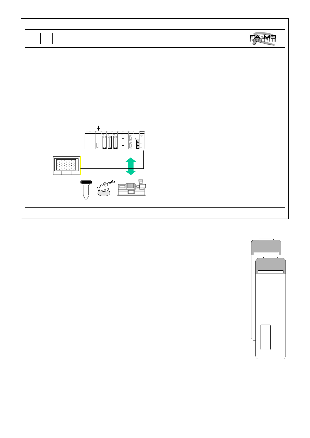
The personal computer link:
(1) Is a communication link that is dedicated for the FA-M3 R and allows the device data within
sequence CPUs to be read or written from other equipment (personal computers, display units,
etc.) without intervention of a sequence program, and also allows a sequence program to notify
events.
(2) Allows you to select the network hardware specification from RS-232-C, RS-422, and Ethernet as
required.
(3) Allows use of display units from various manufacturers that support the FA-M3 R-specific personal
computer link protocol.
PC/YEWMAC PC/Workstation
Communication Specification Module Name
RS-232-C
RS-422/485 F3LC11-2F
Ethernet F3LE01-5T
* The PROGRAMM ER por t on the C PU m odul e is used.
(F3SP05/21/28/38/53/58)
F3LC11-1
F3LC12-1F
F3SP-*
RS-232-C
RS-232-C
RS-232-C
RS-422
Display unit Display unit
Enthernet
PC/YEWMAC
Public phone line
Modem
Modules that support personal computer link commands:
F3LC11-N personal computer link module
F3LC12-1F personal computer link module
F3SP- sequence CPU module
F3LE01-1N Ethernet interface module
Differences in personal computer link between Ethernet interface module and other modules:
All modules support ASCII-coded commands and responses, but only the Ethernet interface module supports
binary-coded commands and responses. Note that the Ethernet interface module uses different header and
termination codes in ASCII mode from those of other modules.
TI 34M6A01-01E
36
Page 41

P
P
L
L
C
C
Personal Computer Link Modules
A personal computer link module provides the FA-M3 R with the personal computer
link feature via RS-232-C or RS-422/485.
The built-in communications protocol allows connections to be made to other equipment that
supports the same protocol without requiring any program, and facilitates system configuration.
A personal computer link module is typically used to connect display units.
F3LC11-2NF3LC11-1N
FA-M3 R
RS-422/485
RS-232-C
PC, Display Unit, etc.
Display Units, etc.
F3LC11-1, F3LC11-2N and F3LC12-1F Personal Computer Link Modules
Read/Write all devices in sequence CPU modules
Read/Write common variables in the BASIC CPU module
User program for data transmission not needed
Direct connection to a display unit having a programmable controller interface
Run/Stop a sequence CPU module remotely
Load/Save a sequence program
Read sequence program information such as program names, program size
and block names, as well as error logs and user logs
RDY
LC11-1N
C LINK
RDY
LC11-2N
TERMINATOR
2- 4-WIRE
OFF
SD A
SD B
RD A
RD B
SG
SHIELD
C LINK
STATION
NO.
TI 34M6A01-01E
F3LC11-1N
(RS-232C)
F3LC11-2N
(RS-422/485)
37
Page 42

P
P
C
L
C
L
A personal computer or display unit can be connected to the programming port of a
sequence CPU module, providing an instant and low-cost personal computer link.
Personal Computer Link via Programming Port
Display Unit
F3SP-
RS-232-C
FA-M3 R
The same commands are used for personal computer link modules are sequence CPU modules.
Note: The following cables are available for connection from Yokogawa.
Model: KM11-2T, -3T or -4T
Specification: D-sub 9-pin female; approx. 3, 5, or 10 meters long, respectively
Model : KM10C-0C
Specification : D-sub 9-pin female; approx. 0.5 meter long
Note: For details, see the General Specifications, FA-M3 CPU Port Cables (GS 34M6C 91-01E).
TI 34M6A01-01E
38
Page 43

P
P
L
L
C
C
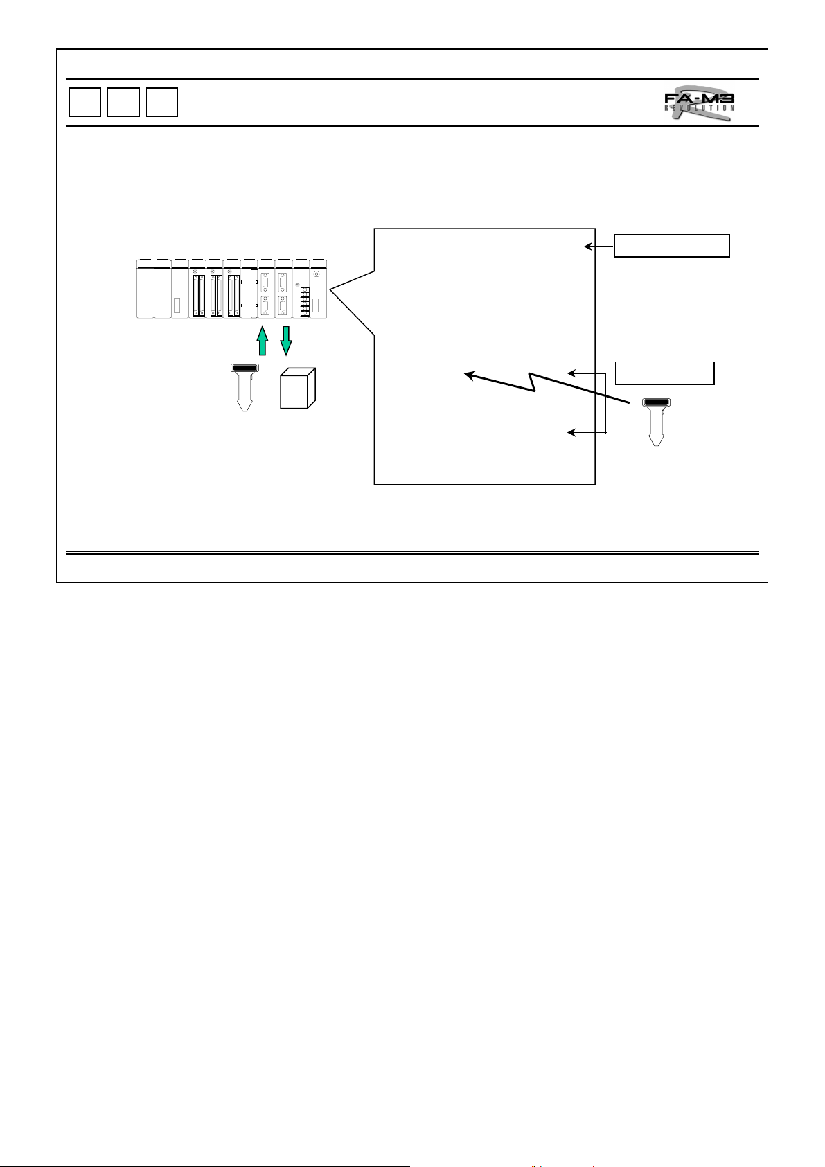
Ethernet Interface Module
The Ethernet interface module enables the FA-M3 R's data to be accessed via Ethernet as one
style of personal computer link. Using this Module, the FA-M3 R's data can be accessed
directly from personal computers and workstations, thus allowing an information system and
control system to be directly linked.
*Remote OME (see pages 29 to 32) is possible from a personal computer using WideField.
Personal Computer
FA-M3 Programming
Tool WideField
Personal Computer and Workstation
Ethernet
FA-M3 R
F3LE01-5T
F3LE01-5T Ethernet Interface Module
The Ethernet interface module provides an IEEE802.3-compliant network connection port
(10Base5/10Base-T), and performs the same functions as those performed by personal
computer link modules (n:n communication) via serial communication.
Remote OME
You can create and modify programs using WideField from a personal computer on the
same network.
Information
System
Control
System
LE01-5T
RDY
SND
RCV
ERR
ETHER
T
Personal Computer Link (access through another node)
Through a node, yon can:
• Monitor and write devices in sequence CPUs from another node on the same network.
• Download, upload, start and stop programs.
• Read/write common variables in the BASIC CPU module.
None of these requires a user program for communication. Both binary-coded and ASCIIcoded commands and responses are supported, allowing for high-speed data transmission.
Event transmission (access to another nodes)
The Ethernet module enables events to be transmitted to another nodes on the same
network.
Note: 10B ase-T requires no external power sup pl y.
When a 10Base5 network is used and the connected Et hernet device requires power to be supplied to its AUI
connector, a 12 V DC power supply must be connected to t he Ethernet module.
TI 34M6A01-01E
AUI
+
-
F3LE01-5T
39
Page 44

P
P
L
L
C
C
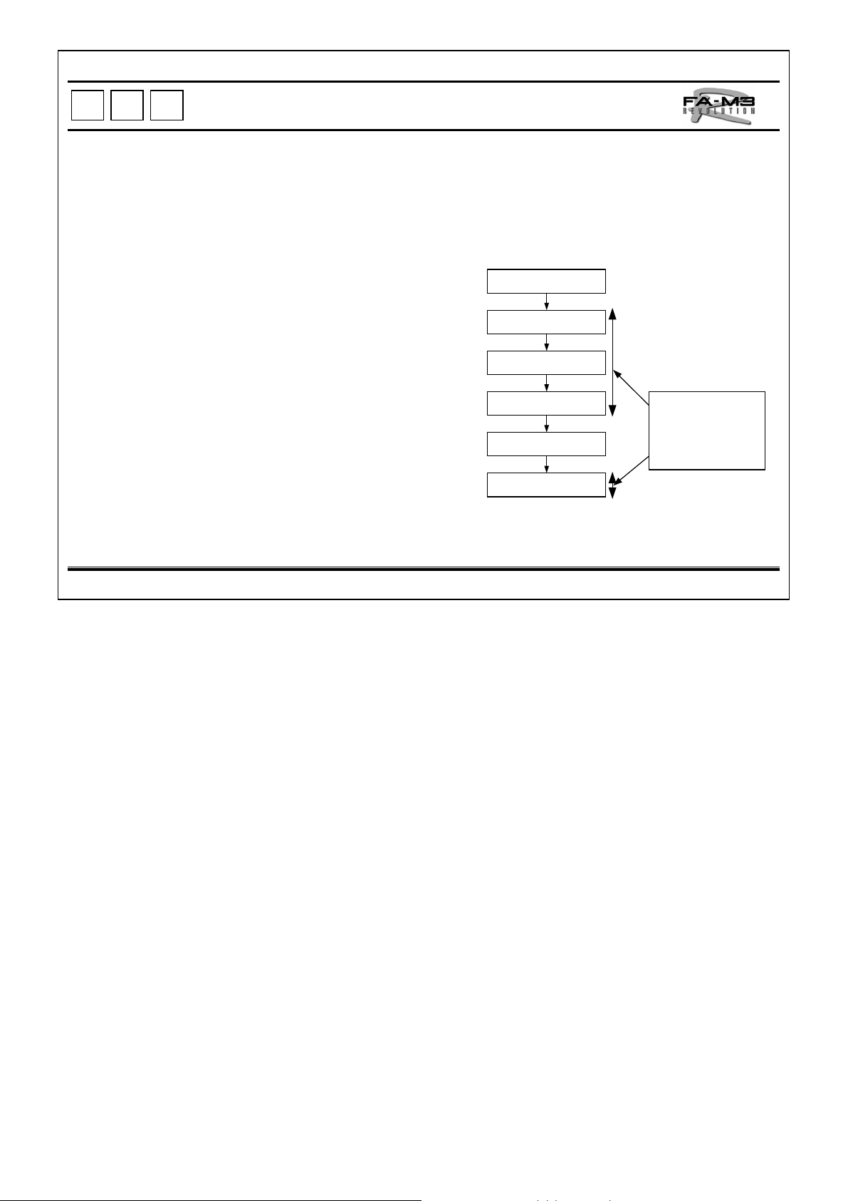
FA Link H Module
High-speed data transmission between FA-M3 R controllers for data
sharing
(4 times faster than the conventional FA link)
F3LP02-0N
Item Specification
Link relays
Link registers
Transmission
speed
Maximum
transmission
distance
Transmission
media
Transmission Speed vs. Transmission Dist ance
Transmission speed
Maximum transmission
distance
Up to 8192
Up to 8192
Max. 1.25 Mbps
(can be selected from 125 Kbps,250 Kbps,625 Kbps,
and 1.25 Mbps)
1 km, 500 m, 200 m or 100 m depending on
the transmission sp ee d
Shieded twist-pair cable
(up to 2048 per link)
(up to 2048 per link)
.
125
Kbps
1 km 500 m 200 m 100 m
F3LP02-0N FA Link H Module
Conventional FA Link
(F3LP01-0N)
250 Kbps
(see the ta ble below).
250
Kbps
625
Kbps
1.25
Mbps
FA-M3 R
FA-M3 R
FA Link H
(F3LP02-0N)
1.25 Mbps
F3LP02-0N
F3LP02-0N
FA Link H
(max. 1.25 Mbps, max. 1 km,
connecting max. 32 stations)
FA link H is a high-speed network for data exchange between FA-M3 R controllers. Up to 32
stations, where one station corresponds to one FA link H module, can be linked together for
data sharing.
z Up to 8 FA link H modules can be installed in an FA-M3 R main unit (for the SP28, SP38,
SP53 or SP58; up to 2 modules for the SP21) to allow data links to be structured
hierarchically.
z The numbers of link devices can be set arbitrarily for each CPU.
z There are two operation modes for each FA link H: normal mode and high-speed mode. In
the normal mode, up to 2048 link relays and 2048 link registers can be used per module. In
the high-speed mode, up to 1024 link relays and 1024 link registers can be used per
module.
z The transmission speed can be selected from 125 Kbps, 250 Kbps, 625 Kbps and 1.25
Mbps. The transmission speed setting determines the maximum transmission distance as 1
km, 500 m, 200 m and 100 m, respectively.
z The bus-like multi-drop network topology facilitates expansion of the link.
z Modules can be easily connected to each other with shielded twist-pair cables.
Note: When connecting to an FA500 use the F3LP01-0N FA link module.
RDY
SND
ERR
FA LINK
LP02-0N
STATION NO.
TERMINATOR
OFF ON
A
B
SG
SHIELD
F3LP02-0N
TI 34M6A01-01E
40
Page 45

P
P
F3LP12-0N
L
L
C
C
Fiber-optic FA Link H Module
High-speed data transmission between FA-M3 R controllers for data
sharing, Fi ber-optic cable
F3LP12-0N
Item Specification
Link relays
Link registers
Transmission
speed
Maximum
transmission
distance
Network
topology
Transmission
media
Up to 8192
Up to 8192
Max. 1.25 Mbps
1 km between units
10 km of total extension
Daisy chain
Two-core fiber-optic cable
(up to 2048 per system)
(up to 2048 per system)
FA-M3 R
Fiber-optic cables
F3LP12-0N
Fiber-optic FA Link H
(max. 1.25 Mbps,max. 10 km,
connecting max. 32 stations)
Daisy chain confi guration
F3LP12-0N Fiber-optic FA Link H Module
Fiber-optic FA link H is a high-speed fiber-optic network for data exchange between FA-M3 R
controllers. Up to 32 stations, where one station corresponds to one FA link H module, can be
linked together for data sharing.
z Up to 8 fiber-optic FA link H modules can be installed in an FA-M3 R main unit (for the
SP28, SP38, SP53 or SP58; up to 2 modules for the SP21) to allow data links to be
structured hierarchically.
z The numbers of link devices can be set arbitrarily for each CPU.
z There are two operation modes for each FA link H: normal mode and high-speed mode. In
the normal mode,up to 2048 link relays and 2048 link registers can be used per module. In
the high-speed mode, up to 1024 link relays and 1024 link registers can be used per
module.
z High noise immunity of fiber-optic cables allows a transmission speed of as fast as 1.25
Mbps over maximum inter-station distances of 1 km and the total extension of 10 km.
z The network topology is daisy chain.
RDY
SND
ERR
LP12-0N
FA LINK
STATION NO.
1
2
F3LP12-0N
TI 34M6A01-01E
41
Page 46

P
P
L
L
C
C
UT Link Module
Easy Monitoring and S etting of UT Series Temperature Controll ers
Features:
(1) Data access from ladder programs without considering communications. Data can be acquired with just a READ
instruction.
(2) Up to a tot al of 31 UT series temperature c ontrollers (UT750, UP750, UP550, UT350 and U T 2000*) and µRS1800*
recorders can be connected.
(3) Field data from the above i nstru ments can be acqui red and st ored to data regist ers via h ardwar e connect ions only , thus
allowing field data to be accessed by accessing t he data registers.
Display Unit
FA-M3 R
F3LC51-2N UT Link
UT750
UP750 UP550 UT350
µRS1800*
UT2000*
Up to 16 UT2000s and µRS18 00s in total
*
F3LC51-2N UT Link Module
The UT link module achieves simple connections between an FA-M3 R controller and
external instruments, such as temperature controllers, that support the protocol and
commands of the personal computer link.
z The module continuously refreshes the data of the linked external instruments. Without a
user program for communication, data exchange with external instruments can be
performed by accessing the registers of the module. Data access can also be performed
upon occurrence of a specified event.
z A total of up to 31 UT temperature controllers and µR1800* recorders can be connected
per UT link module over the maximum cable extension of 1200 m (for RS-485).
Note: T he UT350, UT550, UT750, UP750 and UT20 00 are products Yokogawa M&C corporation.
RDY
LC51-2N
TERMINATOR
2- 4-WIRE
OFF
SD A
SD B
RD A
RD B
SG
SHIELD
UT LINK
TI 34M6A01-01E
F3LC51-2N
42
Page 47

P
P
C
L
C
L
Multi-Link Module
Easy replacement of oth er manufacturer's PLC to FA-M3 R
allowing the use of existing user-developed resources
Where a personal computer is connected to another manufacturer's* PLC, the PLC
can be replaced by the FA-M3 R and the existing PC applications can still be used.
The existing equipment that supports other PLC's* protocol can access the FA-M3 R.
PC
Software
Display Un it, etc.
Other Manufacturer's PLC
Can still be used.
· High speed 5K steps/0.95 ms
· Postcard size
· No changes to external equipment
· Existing software and settings for PC
and display units can continue to be
used.
* The current version of the F3LC21-1N multi-link module only supports of PLCs from Mitsubishi Electric
Corporati o n and OM R ON C orp or at io n.
z The com pany names appearing in this document are regis tered trademarks of their respec tive holders.
z For details on models whose conne ction has been verifie d, consult your nearest Yokogawa representative or
sales office.
PC
Software
FA-M3 R
Display Un it, etc.
F3LC21-1N Multi-link Module
The multi-link module is a communication module for connecting to a higher level computer
such as a personal computer or FA computer, or a display unit via an RS-232-C interface on a
point-to-point** basis.
RDY
LC21-1N
M LINK
z Supports the computer link commands of Mitsubishi Electric Corporation's PLCs and high-
level link commands of OMRON Corporation's PLCs, enabling connection to external
equipment that can connect these PLCs.
Can read and write devices.
z
z No need for ladder program for communication.
z Read/write from/to devices even the respective ladder programs are not running
z Run/stop FA-M3 R remotely.
** Using an RS-232-C/RS-485 adapter enables the FA-M3 R controller t o be al l ocated on the same comm unic at i on
line as another PLCs (where the stat i on number is fixed to 00).
Display Unit
RS-232-C/RS-485
RS-485
adapter
FA-M3 R Other
Manufacturer's PLC
Manufacturer's PLC
Other
F3LC21-1N
TI 34M6A01-01E
43
Page 48

P
P
C
L
C
L
GP-IB Communication Module
High-speed Communication with Testing and Measuring Instruments as Well
as Various Signal Generators
Accessible from ladder and BASIC programs
Enables waveform generators, digital multimeters, LCR meters, etc. to be connected, their
signal generation conditions to be set, and the measured data to be read easily via GP-IB,
thus reducing the leadtime of testing and inspections.
Display Unit
Printer
FA-M3
GP-IB communication
Programmable DC
Voltage/Current Generator
Digital Multimeter Digital
Multi-thermometer
F3GB01-0N GP-IB Communication Module
The GP-IB communication module connects the FA-M3 R to instruments having a
GP-IB interface, such as testing and measuring instruments.
z Has one GP-IB port.
z Supports GP-IB controller functions for transmission of interface
messages.
Note: Conf orms to ANSI/IEEE standar d 488.
RDY
TALK
LSTN
GB01-0N
GP-IB
ADDRESS
TI 34M6A01-01E
F3GB01-0N
44
Page 49

P
P
RS-232-C and RS-422/485 Communication Modules (1)
C
L
C
L
Access from Ladder and BASIC Programs to Field Instruments via RS-232-C or
RS-422/485 Interface
F3SP
-
Barcode
Reader
Sequence CPU Module
BASIC CPU Module
N
Remote ID, etc. Peripherals
F3RZ81-0N
F3RZ91-0N
Ladder sequence + ladder communication
BASIC program + serial communication
F3BP20-0N
F3BP30-0N
Barcode
Reader
Ladder Sequence + Ladder Communication
F3RZ81-0N RS-232-C Communication Module
z The F3RZ81-0N module is used to carry out RS-232-C communication
from ladder program inside a sequence CPU module.
z The module has one RS-232-C port with a D-sub 9-pin connector and
allows the maximum transmission distance of 15 meters.
F3RZ91-0N RS-422 Communication Module
z The F3RZ91-0N module is used to carry out RS-422 or RS-485
communication from a ladder program inside a sequence CPU module.
z The module has screw terminals for RS-422/485 port and allows the
maximum transmission distance of 1200 meters.
F3RS22-0N
F3RS41-0N
Remote ID, etc. Peripherals
RDY
RS232
RZ81-0N
RDY
RZ91-0N
TERMIN ATOR
2- 4-WIRE
OFF
SD A
SD B
RD A
RD B
SG
SHIELD
RS422
TI 34M6A01-01E
F3RZ81-0N F3RZ91-0N
45
Page 50

P
P
L
L
C
C
RS-232-C and RS-422 Communication Modules (2)
Access from a Ladder Sequence Program by
Combination of a Sequence CPU Module and a
Ladder Communication Module
-
F3SP
Barcode Reader
N
F3RZ81-0N (with one RS-232-C port)
F3RZ91-0N (with one RS-422/485 port)
Access from BASIC Program by Combination of a
BASIC CPU Module and a Serial Communic ation
Module
ON INT WARI@
LOOP@
WARI@
WAIT
GOTO LOOP
ENTER
OUTPUT
RETURN
F3BP20-0N
F3BP30-0N
F3RS22-0N (with two RS-232-C ports)
F3RS41-0N (with one RS-422/485 port)
Barcode Reader
BASIC Program + Serial Communication
F3RS22-0N RS-232-C Communication Module
z The F3RS22-0N module is used with a BASIC CPU module to carry out
RS-232-C communication.
z The module has two RS-232-C ports with D-sub 9-pin connectors and
allows the maximum transmission distance of 15 meters.
z BASIC statements for transmission and reception to/from communication
lines are provided.
Note: T hi s module is dedicated for use with a BAS I C CPU module.
F3RS41-0N RS-422 Communication Module
z The F3RS41-0N module is used with a BASIC CPU module to carry out
RS-422 or RS-485 communication.
z The module has screw terminals for one RS-422/485 port and allows
maximum transmission distance of 1200 meters.
z BASIC statements for data transmission and reception to/from the
communication lines are provided.
RDY
RS41-0N
TERMINATOR
2- 4-WIRE
OFF
SD A
SD B
RD A
RD B
SG
SHIELD
RS422
RS22-0N
1
2
RDY
RS232
F3RS22-0N F3RS41-0N
This module is dedicated for use with a BASIC CPU module.
Note:
TI 34M6A01-01E
46
Page 51

P
P
C
L
C
L
FA-M3 Value
FA-M3's extensive functions and unrivaled performance come at an economic price.
A special set of CPU, power supply and I/O modules is offered
at a discount price as a value pack
The FA-M3 value pack,F3SC21-1N,is a compact controller composed of:
An F3BU04-0N four-slot base module
An F3SP05-0P sequence CPU module with power supply unit and memory
An F3WD64-3N input/output module with 32 input and 32 outputs
Item Specification
F3BU04-0N base
module
F3SP05-0P
sequence CPU
module
F3WD64-3N
input/output module
Number of slots 4 (available spare slots: 2)
Input power
Power
supply unit
Sequence
CPU
Input 32 DC voltage inputs,rated voltage: 24 VDC
Output 32 transistor contacts(sink);rated voltage: 24 VDC
supply voltage
Rated output 5 V DC, 2.0 A
Others The same as F3PU10-0N
Programming
language
Instructions BASIC instructions:25 kinds; application instructi ons:227 kinds
Program
capacity
Number of I/O
points
Others The same as F3SP21-0N
100-240 V AC, single phase, 50/60 Hz
Structured ladder, mnemonic
5K steps (can be saved to a ROM)
Max.2048
F3SC21-1N Value Pack
z Ultra-compact to save space inside the panel.
z The sequence CPU module can receive a universal power supply voltage ranging from 100 to 240 V AC, so
the power supply need not be considered.
z High-speed execution of instructions facilitates development of applications with a fast response.
z Installing an optional ROM pack allows programs and data to be saved.
RUN
SP05-0P
RDY
RUN
CPU
PROGRAMMER
14 91317212529
26101418221630
37111519232731
48121620242832
DC IN
WD64-3N
DISPLAY
12
TI 34M6A01-01E
F3SC21-1N
47
Page 52

P
P
C
L
C
L
The fiber-optic FA-bus module enables data to be sent as high-speed as 10 Mbps. Modules
in subunits can handled like those in the main unit with no effect on the scan time. (Data
refresh rate: 1 ms for 1024 devices)
No transmission delay by direct access to I/O devices
Not only digital I/O modules but also almost all the modules including analog I/O, temperature
controller and pulse input modules installed in a subunit can be handled.
Up to 7 fiber-optic FA-bus modules (for up to 7 subunits) can be installed in main unit for the
maximum number of I/O points allowed for the CPU module used.
Fiber-optic FA-bus Module
F3LR01-0N
200 m 200 m
Fiber-optic cable
Up to 7 lines
I/O module
F3LR01-0N Fiber-optic FA-bus Module
The fiber-optic FA-bus module is an interface module used to configure a fiber-optic FA-bus
system to perform distributed control. To build the ideal remote I/O system, simply install fiberoptic FA-bus modules in an FA-M3 R main unit and in subunits, and connect them with fiberoptic FA-bus cables.
z Many advanced modules can be installed in subunits, and the modules can be accessed in
the same way as the modules in the main unit. (The FA link, FA link H, fiber-optic FA link H
and Ethernet interface modules are exceptions.)
z No specific configuration settings are required for remote I/O.
z Fiber-optic data transmission eliminates being affected by noise.
Fiber-optic cable
I/O module
RDY
ERR
LR01-0N
SUB UNIT NO.
REMOTE
TI 34M6A01-01E
F3LR01-0N
48
Page 53

P
P
L
L
C
C
Fiber-optic FA-bus Type 2 Module
Multi-station remote I/O system with high-speed transmission
over a long distance
Main unit
F3LR02-0N
Item Specification
Transmission
speed
Transmission
media
Transmission
distance
Maximum number
of subunits
Network topology Daisy chain or loop
10 Mbps
Two-core fiber optic cable
Between stations : 500 m
Total extension : 1.4 km
56 (32 per line)
Subunit
Daisy Chain
Connections
Loop Connections
Subunit
Subunit
Main unit
Fiber-optic FA-bus
Type 2
Subunit
Subunit
Fiber-optic FA-bus
Type 2
Subunit
Subunit
F3LRO2-ON Fiber-optic FA-bus Type 2 Module
The fiber-optic FA-bus type 2 module is an interface module used to configure a system
for which high distribution of I/O units is required. To build the ideal, highly distributed
remote I/O system, simply install fiber-optic FA-bus type 2 modules in an FA-M3 R main
unit and in subunits, and connect them with fiber-optic FA-bus cables.
z Many advanced modules can be installed in subunits, and the modules can be
accessed in the same way as the modules in the main unit. (The FA link, FA link
H, fiber-optic FA link H and Ethernet interface modules are exceptions.)
z A subunit can be distributed to up to 8 subunits.
z Each module has 2 pairs of transmission and reception ports to allow daisy chain
connections.
z If the network is configured by loop connections, it is switched to two daisy chain
networks when there is a line breakage, thus enhancing reliability.
z No specific configuration settings are required for remote I/O.
z Fiber-optic data transmission eliminates being affected by noise.
z For point-to-point connections, use lower-priced F3LR01-0N fiber-optic FA-bus
modules.
RDY
ERR1
ERR2
LR02-0N
REMOTE
Sub Unit
NO.
Left Slot
NO.
1
2
F3LR02-0N
TI 34M6A01-01E
49
Page 54

P
P
L
L
C
C
DeviceNet Interface Module
De Facto Standard, Reduced-cabling System
F3LD01-0N F3LD01-0N
DeviceNet
T-connection T-connection Multi-drop
Split branches
Remote I/O Analog
Display unit
terminal
F3LDO1-ON DeviceNet* Interface Module
The DeviceNet* interface module is used to connect to DeviceNet.*
zWorld-standard open field network
- Field-proven worldwide
- Connectable to various devices sold around the world
Specific-application controller,
mass flow controller,
temperature controller,
robot controller, etc .
Sensors and
actuators
Data processing
devices such as
barcode reader
and ID system
Gateway to other
networks such as
sensor bus and
RS-232-C
RDY
DeviceNet
LD01-0N
NODE
ADDRESS
zAdopted as the standard sensor bus by SEMI **
- Ideal for semiconductor manufacturing equipment
zFlexible connections
- Multi-drop connection with T-connectors allows flexible cabling and network
expansion and modification.
zVarious applications supported
- Extension distance: Max. 500 m (when using a thick cable with a transmission
speed of 125 kbps)
- Transmission speed: Max. 500 kbps (with the cable extension distance of 100 m or
less)
- Number of devices connected: Up to 64 (including the master device)
zExtensive transmission data
- Up to 8000 inputs and 8000 outputs, a total of up to 16,000 input/output
points
* DeviceNet is a registered trademark of Open Devi ceNet Vendor Associati on.
** A cronym of Semiconductor Equipment and Materials Internation al
TI 34M6A01-01E
TERMINATOR
OFF ON
F3LD01-0N
50
Page 55

P
P
C
L
C
L
24 V DC Power Supply Module
DC Power Supply Module Added to Lineup
The DC power supply module makes full use of the FA-M3 R's features of compactness,
light-weight, and low power consumption. It is ideal for installing an FA-M3 R controller
inside battery-driven equipment such as an automatic guided vehicle (AGV).
A wide range of allowable power supply voltage fluctuations from 15.6 to 31.2 V
F3PU26-ON Power Supply Module
Item Specif ication
Supply voltage 24 V DC
Allowable supply
voltage fluctuations
Maximum pow er
consum ption
15.6 to 31.2 V DC
33.1 W
Rated output voltage 5 V DC
Rated output current 4.3 A
At least 5 MΩ at 500 V DC betw een DC
Insulation resistance
input terminals and FG (frame ground)
terminal
W ithstanding voltage
1500 V AC for 1 m inute between D C input
terminals and FG (fram e g round) terminal
Ins ens itive
instantaneous power
20 ms
failu r e time
W ithstands noise of 1500 Vp-p for 1 µs with
Noise immunity
the rise time of 1 ns at frequencies of 25 to
60 Hz (tested using a noise simulator).
FA-M3 R
F3PU26-0N
Rated output voltage: 5 V DC
Rated output current: 4.3 A
RDY
POWER
PU26-0N
FAIL
OUTPUT
FAIL1
COM
FAIL2
FG
LG
-
+
INPUT
24VDC
F3PU26-0N Module
TI 34M6A01-01E
51
Page 56

P
P
C
L
C
L
The FA-M3 R employs market standard connectors for its 32-and 64-point I/O modules, so a huge
range of cables and terminal blocks from other vendors can be used.
Of course, the FA-M3 R offers terminal blocks with a connector and dedicated connector cables.
Market Standard Connectors
FA-M3 R
KM55-0 dedicated cables
TA50-0N
(with M3.5 screw terminals)
TAS0-0N, TA50-1N and TA60-0N Terminal Blocks
KM-50-0 Dedicated Cables
(with M3 screw t erminals)
TA50-0N
TA60-0N
(with European standard
clamp-on terminals)
TI 34M6A01-01E
52
Page 57

z
Windows and Excel are regist ered trademarks of Microsoft Corporation.
z
Intel, MMX, and Pentium are trademarks or registered trademarks of Intel Corporation.
z
Ethernet is a registered t rademark of XEROX Corporation.
z
Other product and company names appearing in this document are trademarks or registered t rademarks
of their respective holders.
TI 34M6A01-01E
 Loading...