

Page 1

User’s
Manual
IM 34M6H55-02E
Positioning Modules
(with Multi-channel Pulse Output)
Model: F3YP14-0N, F3YP18-0N
IM 34M6H55-02E
1st Edition
Yokogawa Electric Corporation
Page 2

i
IM 34M6H55-02E 1st Edition : Apr.1, 2002-00
Applicable Product
zzzz Range-free Multi-controller FA-M3
Model : F3YP14-0N, F3YP18-0N
Name: Positioning Module (with Multi-Channel Pulse Output)
The document number and document model code for this manual are given below:
Refer to the document number in all communications; also refer to the document
number or the document model code when purchasing additional copies of this manual.
Document No. : IM 34M6H55-02E
Document Model Code : DOCIM
Media No. IM 34M6H55-02E (CD) 1st Edition : Apr. 2002 (AR)
All Rights Reserved Copyright © 2001, Yokogawa Electric Corporation
Page 3
ii
IM 34M6H55-02E 1st Edition : Apr.1, 2002-00
Important
About This Manual
- This Manual should be passed on to the end user.
- Before using the controller, read this manual thoroughly to have a clear
understanding of the controller.
- This manual explains the functions of this product, but there is no guarantee that
they will suit the particular purpose of the user.
- Under absolutely no circumstances may the contents of this manual be transcribed
or copied, in part or in whole, without permission.
- The contents of this manual are subject to change without prior notice.
- Every effort has been made to ensure accuracy in the preparation of this manual.
However, should any errors or omissions come to the attention of the user, please
contact the nearest Yokogawa Electric representative or sales office.
Safety Precautions when Using/Maintaining the Product
The following safety symbols are used on the product as well as in this manual.
Danger. This symbol on the product indicates that the operator must follow the
instructions laid out in this instruction manual to avoid the risk of personnel injuries,
fatalities, or damage to the instrument. Where indicated by this symbol, the manual
describes what special care the operator must exercise to prevent electrical shock
or other dangers that may result in injury or the loss of life.
Protective Ground Terminal. Before using the instrument, be sure to ground this
terminal.
Function Ground Terminal. Before using the instrument, be sure to ground this
terminal.
Alternating current. Indicates alternating current.
Direct current. Indicates direct current.
Page 4

iii
IM 34M6H55-02E 1st Edition : Apr.1, 2002-00
The following symbols are used only in the instruction manual.
WARNING
Indicates a “Warning”.
Draws attention to information essential to prevent hardware damage, software
damage or system failure.
CAUTION
Indicates a “Caution”
Draws attention to information essential to the understanding of operation and
functions.
TIP
Indicates a “TIP”
Gives information that complements the present topic.
SEE ALSO
Indicates a “SEE ALSO” reference.
Identifies a source to which to refer.
- For the protection and safe use of the product and the system controlled by it, be
sure to follow the instructions and precautions on safety stated in this manual
whenever handling the product. Take special note that if you handle the product in
a manner other than prescribed in these instructions, the protection feature of the
product may be damaged or impaired. In such cases, Yokogawa cannot guarantee
the quality, performance, function or safety of the product.
- When installing protection and/or safety circuits for this product or the system
controlled by it, the user should install them outside this product.
- If component parts or consumables are to be replaced, be sure to use parts
specified by the company.
- If you want to use this product in a system which directly affects or threatens human
lives and safety — such as nuclear power equipment, devices using radioactivity,
railway facilities, aviation facilities and medical equipment, please contact your
nearest Yokogawa Electric representative.
- Do not attempt to modify the product.
Exemption from Responsibility
- Yokogawa Electric Corporation (hereinafter simply referred to as Yokogawa Electric)
makes no warranties regarding the product except those stated in the WARRANTY
that is provided separately.
- Yokogawa Electric assumes no liability to any party for any loss or damage, direct or
indirect, caused by the use or any unpredictable defect of the product.
Page 5

iv
IM 34M6H55-02E 1st Edition : Apr.1, 2002-00
Software Supplied by the Company
- Yokogawa Electric makes no other warranties expressed or implied except as
provided in its warranty clause for software supplied by the company.
- Use the software with one computer only. You must purchase another copy of the
software for use with each additional computer.
- Copying the software for any purposes other than backup is strictly prohibited.
- Store the original media, such as floppy disks, that contain the software in a safe
place.
- Reverse engineering, such as decompiling of the software, is strictly prohibited.
- No portion of the software supplied by Yokogawa Electric may be transferred,
exchanged, or sublet or leased for use by any third party without prior permission by
Yokogawa Electric.
Page 6

v
IM 34M6H55-02E 1st Edition : Apr.1, 2002-00
General Requirements for Using the FA-M3
zzzz
Avoid installing the FA-M3 in the following locations:
- Where the product will be exposed to direct sunlight, or where the operating
temperature exceeds the range 0°C to 55°C (32°F to 131°F).
- Where the relative humidity is outside the range 10 to 90%, or where sudden
temperature changes may occur and cause condensation.
- Where corrosive or flammable gases are present.
- Where the product will be exposed to direct mechanical vibration or shock.
- Where the product may be exposed to extreme levels of radioactivity.
zzzz Use the correct types of wire for external wiring:
- Use copper wire with temperature ratings greater than 75°C.
zzzz Securely tighten screws:
- Securely tighten module mounting screws and terminal screws to avoid problems
such as faulty operation.
- Tighten terminal block screws with the correct tightening torque as given in this
manual.
zzzz Securely lock connecting cables:
- Securely lock the connectors of cables, and check them thoroughly before turning
on the power.
zzzz Interlock with emergency-stop circuitry using external relays:
- Equipment incorporating the FA-M3 must be furnished with emergency-stop circuitry
that uses external relays. This circuitry should be set up to interlock correctly with
controller status (stop/run).
zzzz Ground for low impedance:
- For safety reasons, connect the [FG] grounding terminal to a Japanese Industrial
Standards (JIS) Class D Ground
*1
(Japanese Industrial Standards (JIS) Class 3
Ground). For compliance to CE Marking, use cables such as twisted cables which
can ensure low impedance even at high frequencies for grounding.
*1 Japanese Industrial Standard (JIS) Class D Ground means grounding resistance of 100 ohms max.
zzzz Configure and route cables with noise control considerations:
- Perform installation and wiring that segregates system parts that may likely become
noise sources and system parts that are susceptible to noise. Segregation can be
achieved by measures such as segregating by distance, installing a filter or
segregating the grounding system.
zzzz Configure for CE Marking Conformance:
- For compliance to CE Marking, perform installation and cable routing according to
the description on compliance to CE Marking in the “Hardware Manual”
(IM34M6C11-01E).
zzzz Keep spare parts on hand:
- Stock up on maintenance parts including spare modules, in advance.
Page 7

vi
IM 34M6H55-02E 1st Edition : Apr.1, 2002-00
zzzz Discharge static electricity before operating the system:
- Because static charge can accumulate in dry conditions, first touch grounded metal
to discharge any static electricity before touching the system.
zzzz Never use solvents such as paint thinner for cleaning:
- Gently clean the surfaces of the FA-M3 with a soft cloth that has been soaked in
water or a neutral detergent and wringed.
- Do not use volatile solvents such as benzine or paint thinner or chemicals for
cleaning, as they may cause deformity, discoloration, or malfunctioning.
zzzz Avoid storing the FA-M3 in places with high temperature or humidity:
- Since the CPU module has a built-in battery, avoid storage in places with high
temperature or humidity.
- Since the service life of the battery is drastically reduced by exposure to high
temperatures, take special care (storage temperature should be from –20°C to
75°C).
- There is a built-in lithium battery in a CPU module and temperature control module
which serves as backup power supply for programs, device information and
configuration information. The service life of this battery is more than 10 years in
standby mode at room temperature. Take note that the service life of the battery
may be shortened when installed or stored at locations of extreme low or high
temperatures. Therefore, we recommend that modules with built-in batteries be
stored at room temperature.
zzzz Always turn off the power before installing or removing modules:
- Failing to turn off the power supply when installing or removing modules, may result
in damage.
zzzz Do not touch components in the module:
- In some modules you can remove the right-side cover and install ROM packs or
change switch settings. While doing this, do not touch any components on the
printed-circuit board, otherwise components may be damaged and modules may fail
to work.
Page 8

vii
IM 34M6H55-02E 1st Edition : Apr.1, 2002-00
Introduction
Overview of the Manual
This user’s manual, “Positioning Module with Multi-channel Pulse Output,” explains the
specifications and provides information required to operate the positioning modules,
F3YP14-0N and F3YP18-0N, with an FA-M3 controller.
Other Manuals
Refer to the following manuals.
zzzz For sequence CPU functions:
- Sequence CPU Modules - Functions (for F3SP21, F3SP25 and F3SP35)
(IM 34M6P12-02E)
- Sequence CPU Modules - Functions (for F3SP28, F3SP38, F3SP53 and F3SP58)
(IM 34M6P13-01E)
zzzz For sequence CPU instructions:
- Sequence CPU Modules - Instructions (IM 34M6P12-03E)
zzzz For commands and responses of the PC Link function:
- Personal Computer Link Command (IM34M6P41-01E)
● For creating programs using ladders:
- FA-M3 Programming Tool WideField (IM 34M6Q14-01E)
- FA-M3 Programming Tool WideField - Application (IM 34M6Q14-02E)
zzzz For the FA-M3 specifications and configurations
*1
, installation and
wiring, test run, maintenance, and module installation limits for the
whole system:
*1: Refer to the relevant product manuals for specifications except for power supply modules, base modules,
input/output modules, cables and terminal units.
- Hardware Manual (IM 34M6C11-01E) version 8 or later
Page 9

viii
IM 34M6H55-02E 1st Edition : Apr.1, 2002-00
Copyrights and Trademarks
Copyrights
Copyrights of the programs and online manual included in this CD-ROM belong to
Yokogawa Electric Corporation.
This online manual may be printed but PDF security settings have been made to prevent
alteration of its contents.
This online manual may only be printed and used for the sole purpose of operating this
product. When using a printed copy of the online manual, pay attention to possible
inconsistencies with the latest version of the online manual. Ensure that the edition
agrees with the latest CD-ROM version.
Copying, passing, selling or distribution (including transferring over computer networks)
of the contents of the online manual, in part or in whole, to any third party, is strictly
prohibited. Registering or recording onto video tapes and other media is also prohibited
without expressed permission of Yokogawa Electric Corporation.
Trademarks
The trade names and company names referred to in this manual are either trademarks
or registered trademarks of their respective companies.
Page 10

Toc-1
IM 34M6H55-02E 1st Edition : Apr.1.2002-00
CONTENTS
Applicable Product ................................................................................... i
Important .................................................................................................. ii
Introduction ............................................................................................ vii
Copyrights and Trademarks................................................................. viii
1. Overview........................................................................................ 1-1
2 Specifications ............................................................................... 2-1
2.1 General Specifications ............................................................................ 2-1
2.2 Operating Environment........................................................................... 2-1
2.3 Model and Suffix Codes .......................................................................... 2-1
2.4 Components and Functions ................................................................... 2-2
2.5 External Dimensions ...............................................................................2-3
2.6 Terminal Assignments and Connections ..............................................2-4
2.7 Applicable External Interface Connectors ............................................2-5
2.8 Attaching and Detaching Modules......................................................... 2-6
3. Function Overview ....................................................................... 3-1
3.1 Positioning Operation ............................................................................. 3-2
3.2 Jog Stepping ............................................................................................ 3-4
3.3 Contact Inputs.......................................................................................... 3-5
3.4 Z-phase Encoder Input............................................................................ 3-5
3.5 Origin Search ...........................................................................................3-5
3.6 Automatic Origin Search......................................................................... 3-7
3.7 Deviation Pulse Clear Signal Output ...................................................3-10
3.8 Linear-Interpolated Operation .............................................................. 3-11
3.9 Changing Speed during Operation ...................................................... 3-12
3.10 Changing Target Position during Positioning .................................... 3-13
3.11 Saving Entry Parameters ...................................................................... 3-14
4. Parameters.................................................................................... 4-1
4.1 Parameters ...............................................................................................4-1
4.1.1 Entry Parameters.......................................................................... 4-4
4.1.2 Command Parameters .................................................................4-5
4.2 Required Parameters for Each Command ............................................4-6
4.3 Description of Parameters ...................................................................... 4-7
4.3.1 Entry parameters .......................................................................... 4-7
FA-M3
IM 34M6H55-02E 1st Edition
Positioning Modules (with Multi-channel Pulse Output)
Model: F3YP14-0N, F3YP18-0N
Page 11

Toc-2
IM 34M6H55-02E 1st Edition : Apr.1.2002-00
4.3.2 Command Parameters .................................................................4-9
4.4 Example for Setting Entry Parameters ................................................4-11
5. Status............................................................................................. 5-1
5.1 List of Status ............................................................................................ 5-2
5.2 Description of Statuses........................................................................... 5-3
6. Input/Output Relays ..................................................................... 6-1
6.1 Output Relays...........................................................................................6-1
6.2 Input Relays..............................................................................................6-2
7. Accessing Modules ...................................................................... 7-1
7.1 Accessing from Sequence CPU ............................................................7-1
7.1.1 Reading Module Statuses ............................................................7-2
7.1.2 Set Parameter ..............................................................................7-3
7.1.3 Reset Error ................................................................................... 7-7
7.1.4 Jog Stepping................................................................................. 7-9
7.1.5 Origin Search.............................................................................. 7-12
7.1.6 Automatic Origin Search ............................................................ 7-16
7.1.7 Set Current Position ...................................................................7-19
7.1.8 Positioning Operation ................................................................. 7-21
7.1.9 Request to Decelerate and Stop ................................................ 7-24
7.1.10 Request to Stop Immediately .....................................................7-26
7.1.11 Changing Speed during Operation .............................................7-28
7.1.12 Changing Target Position during Positioning ............................. 7-31
7.1.13 Saving Entry Parameters .......................................................... 7-34
7.2 Accessing from a BASIC CPU .............................................................. 7-36
7.2.1 Reading Module Statuses ..........................................................7-37
7.2.2 Set Parameter ............................................................................7-38
7.2.3 Reset Error ................................................................................. 7-39
7.2.4 Jog Stepping............................................................................... 7-40
7.2.5 Origin Search.............................................................................. 7-41
7.2.6 Automatic Origin Search ............................................................ 7-44
7.2.7 Set Current Position ...................................................................7-46
7.2.8 Positioning Operation ................................................................. 7-47
7.2.9 Request to Decelerate and Stop ................................................ 7-49
7.2.10 Request to Stop Immediately .....................................................7-50
7.2.11 Changing Speed during Operation .............................................7-51
7.2.12 Changing Target Position during Positioning ............................. 7-53
7.2.13 Saving Entry Parameters ...........................................................7-55
8. Errors and Troubleshooting ........................................................ 8-1
8.1 Troubleshooting Flow ............................................................................. 8-1
8.2 Error Codes .............................................................................................. 8-2
8.3 Alarm Codes............................................................................................. 8-4
Page 12

Toc-3
IM 34M6H55-02E 1st Edition : Apr.1.2002-00
9. External Interface Signals............................................................ 9-1
9.1 Pulse Output.............................................................................................9-1
9.2 External Contact Input.............................................................................9-2
9.3 Encoder Z-phase Input............................................................................ 9-3
9.4 Deviation Pulse Clear Signal Output .....................................................9-4
10. Examples of Connections to Drivers ........................................ 10-1
10.1 Example of Connection to Oriental Motor Driver ...............................10-2
10.2 Example of Connection to YASUKAWA Electric SII-Series Driver ....10-3
10.3 Example of Connection to Sanyo Denki PZ Series Driver................ 10-4
Revision Information ........................................................................................... i
Page 13

Blank Page
Page 14
1-1
IM 34M6H55-02E 1st Edition : Apr 1, 2002-00
1. Overview
Models F3YP14-0N-and F3YP18-0N are advanced positioning modules (hereinafter
referred to as the modules or positioning modules) used to control servo drivers and
thereby the speed and position of pulse-driven motors. Driven by commands from the
CPU module of the FA-M3 controller, the positioning module generates paths for
positioning and outputs positioning command values in the form of pulse trains.
A single module can control different types of motors/drivers. It can control up to 4
(the F3YP14-0N module) or up to 8 (the F3YP18-0N module) pulse-driven motors or
servomotors. When in use, the positioning modules are attached to the base module of
an FA-M3 controller.
TTTT Features
- Compared to the earlier positioning module, which allows up to 2 controlled axes
per slot, this module allows up to 8 controlled axes per slot.
- With a short startup time (0.1 ms maximum), it can come into action quickly and
operate in synchronization with peripheral equipment.
- It can output speed reference pulses as fast as 3.998 Mpps for servomotors, or
499.75 kpps for pulse-driven motors.
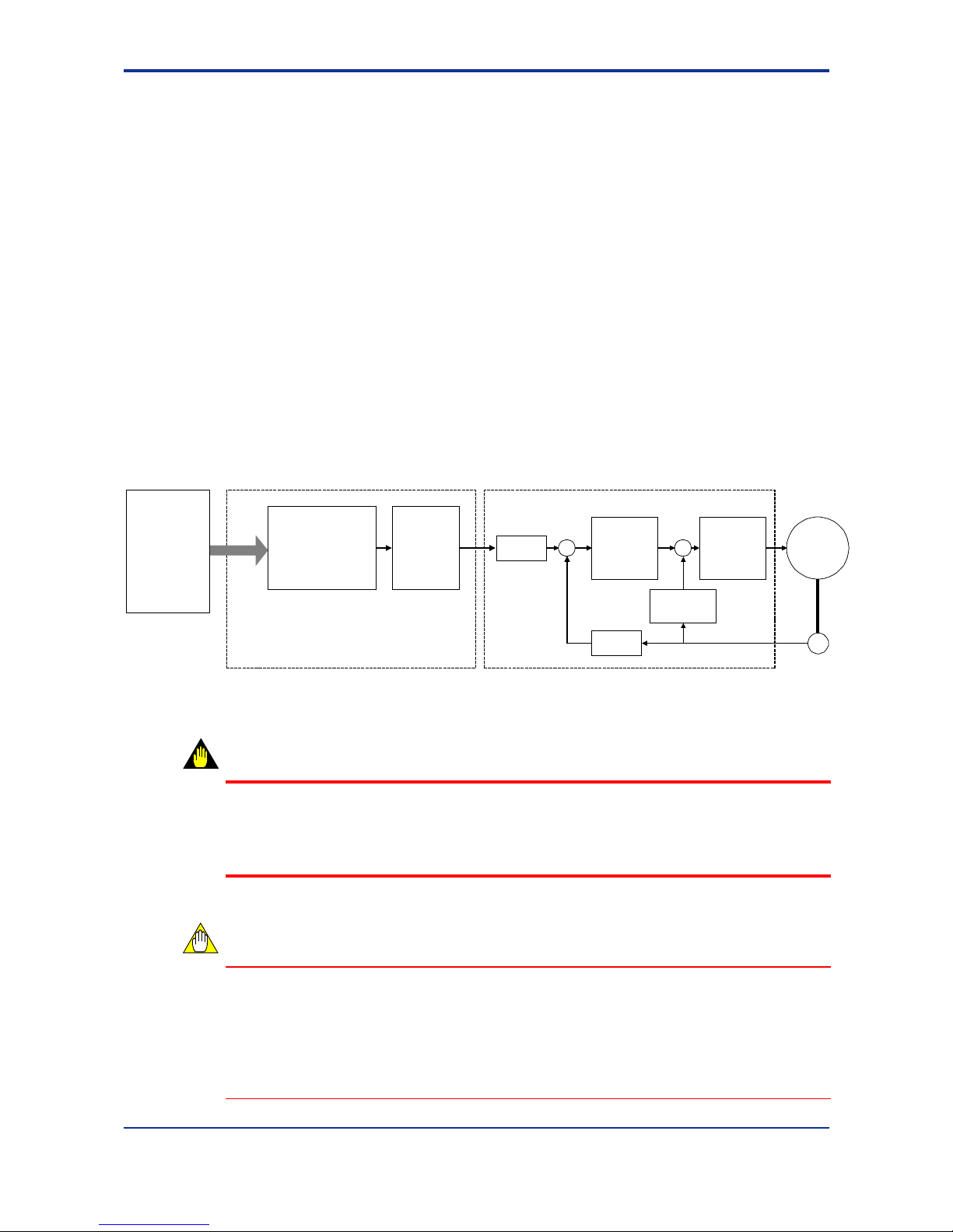
Figure 1.1 Operating Principle of Positioning Module (with Multi-channel Pulse Output)
WARNING
An external emergency stop circuit should be built in, according to the motor
manufacturer’s recommendations, for turning off the power supply and stopping the
motor immediately if it operates in an unexpected manner due to machine fault or
misoperation.
CAUTION
- When controlling a servomotor with the positioning module, choose a positioncontrol servo driver. Speed-control or torque-control servo drivers cannot be used
with the positioning module.
- The maximum pulse output rate is 499.75 kpps for pulse-driven motors. If the
Maximum Speed Selection parameter is set to 3.998 Mpps for pulse-driven motors,
the motor performance cannot be guaranteed.
Higher-level
CPU module
Motor
Encoder
Positioning module Servo driver
Counter
Position
controller
Speed
controller
Pulse
outpu t
Path
generation
Counter
Speed
detector
F010101.VSD
Page 15

Blank Page
Page 16

2-1
IM 34M6H55-02E 1st Edition : Apr 1, 2002-00
2 Specifications
2.1 General Specifications
Specifications
Item
F3YP14-0N F3YP18-0N
Number of controlled axes 4 8
Number of axes controlled
simultaneously
4 8
Pulse output method
RS-422A compliant differential output
Either forward/reverse pulse output or direction/travel pulse output
selectable for each axis
Interpolation
PTP movement
Multi-axis linear interpolation (by CPU module programming)
Command
pulse range
-2,147,483,648 to 2,147,483,647 pulses
Command
speed
0.1 to 3,998,000 pps (for servomotor)
0.1 to 499,750 pps (for pulse-driven motor)
Position
control
Positioning
functions
Absolute/relative positioning command
Target position change during movement
Speed change during movement
Acceleration/deceleration
system
Automatic trapezoidal acceleration/deceleration (starting speed
programmable)
Automatic S-shape acceleration/deceleration (starting speed fixed)
Acceleration/deceleration time
0 to 32,767 ms (programmable for acceleration and deceleration
separately)
Origin position search method
User-definable using a combination of external contact inputs
Normal and automatic origin search operations available
Origin position search speed User-definable within the command speed range
External contact input
Positive and negative limit inputs, home position input, encoder Z-
phase input
External contact output Deviation pulse clear signal
Data backup Using flash memory or CPU module
Startup time*
0.09 ms for one axis
0.25 ms for four axes
0.09 ms for one axis
0.25 ms for four axes
0.5 ms for eight axes
Current consumption 320 mA 380 mA
External power supply 5 V DC, 350 mA 5 V DC, 700 mA
External wiring One 48-pin connector Two 48-pin connectors
External dimensions 28.9 (W) × 100 (H) × 83.2 (D) mm**
Weight 125 g 145 g
* Up to 1 ms delay may be added if another axis is in motion.
** Not including protrusions (see the external dimension diagram for more details).
2.2 Operating Environment
The positioning modules can be used with all models of CPU modules.
2.3 Model and Suffix Codes
Model Suffix
Code
Style
Code
Option
Code
Description
F3YP14 -0N ……… ………
4-axis, multi-channel pulse output
3,998,000 pps max. (for servomotor)
or 499,750 pps max. (for pulse-driven motor)
F3YP18 -0N ……… ………
8-axis, multi-channel pulse output
3,998,000 pps max. (for servomotor)
or 499,750 pps max. (for pulse-driven motor)
Page 17
2-2
IM 34M6H55-02E 1st Edition : Apr 1, 2002-00
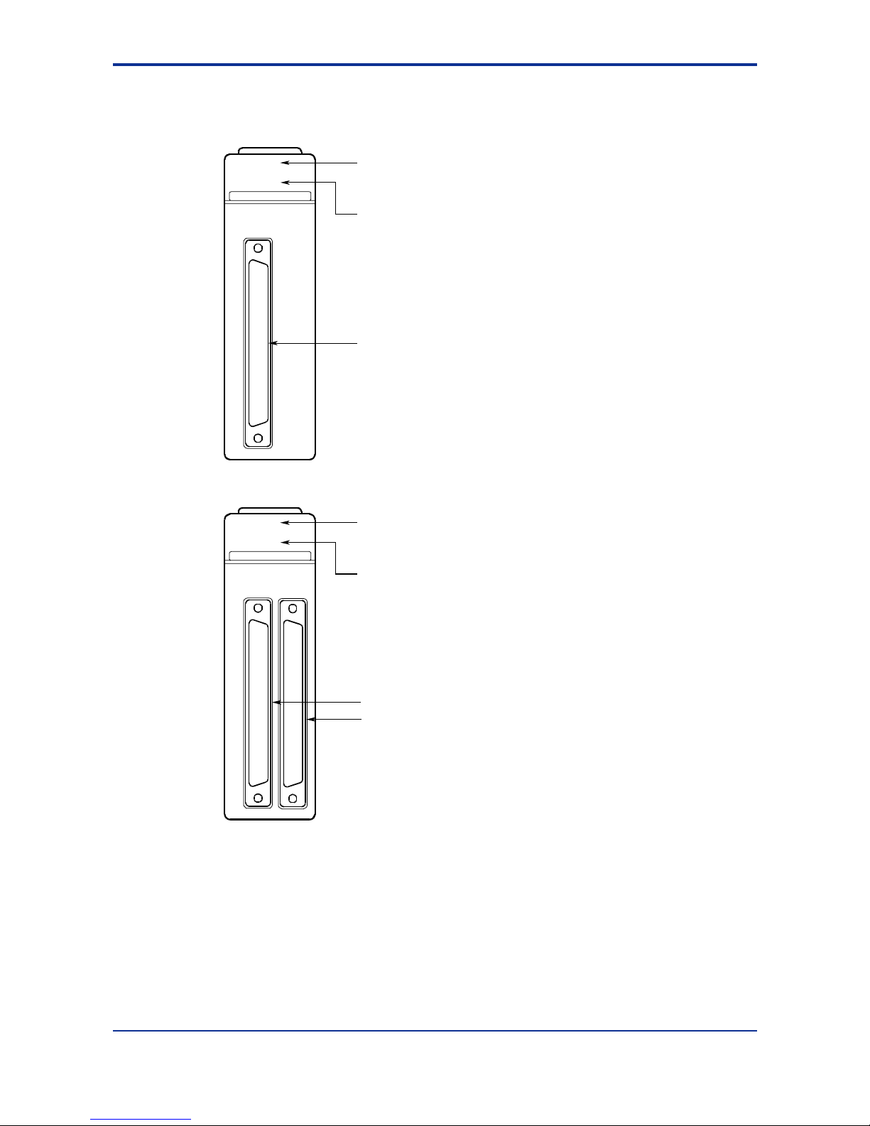
2.4 Components and Functions
RDY indicator:
Lit w hen t he int ern al circuitry is
functioning normally
ERR indicator:
Connector for axes 1 to 4 (48P)
Lit when an error occurs.
For details, refer to Section 8.2,
"Error Codes."
RDY
ERR
POSIT
Connec ts to ext ernal I/O devic es
such as servo motors and limit switches
zF3YP14-0N (4-axis module)
YP14-0N
RDY indicator:
Lit when the internal circuitry is
functioning normally.
ERR indicator:
Connector for axes 1 to 4 (48P)
RDY
ERR
POSIT
zF3YP18-0N (8-axis module)
YP18-0N
F020401.VSD
Lit when an error occurs.
For details, refer to Section 8.2, "Error
Codes."
Connector for axes 5 to 8 (48P)
Connects to external I/O devices such
as servo motor s and limit sw itc hes .
Page 18
2-3
IM 34M6H55-02E 1st Edition : Apr 1, 2002-00
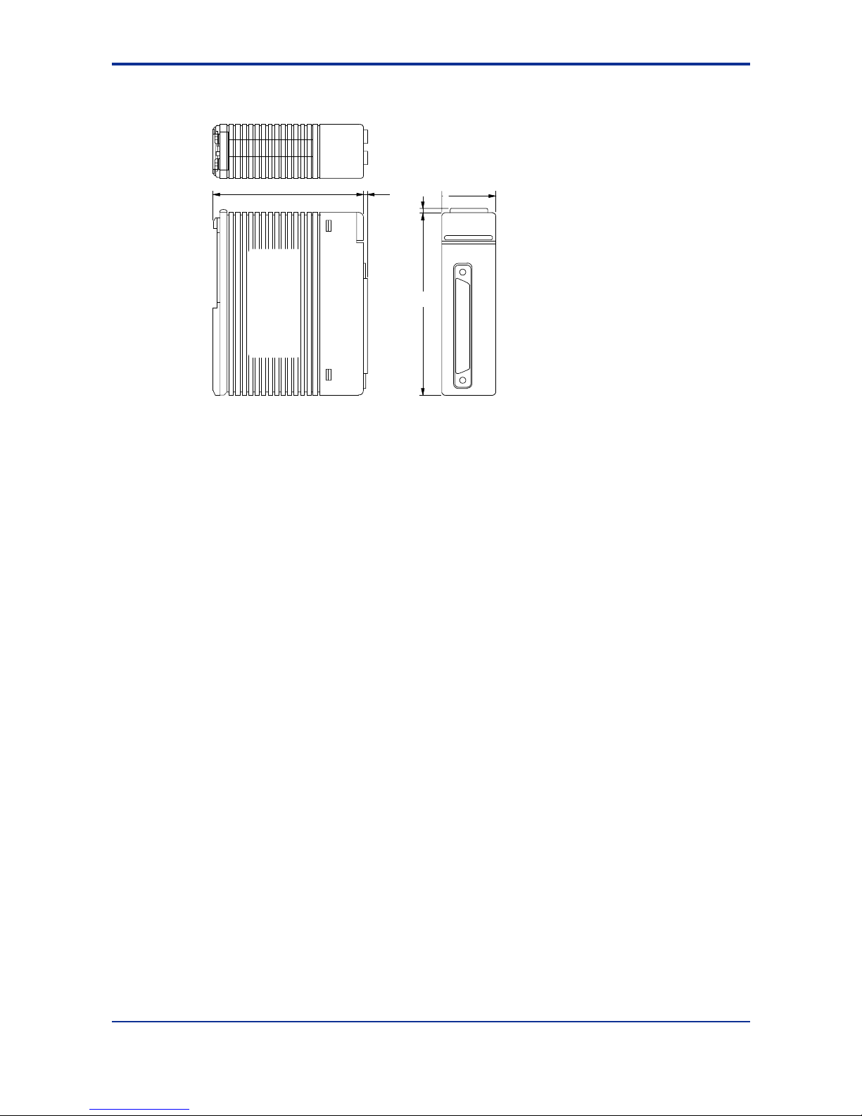
2.5 External Dimensions
* Diagram shown above is for the F3YP14-0N module
83.2 28.9
2
1.3
100
F020501.VSD
Unit: mm
Page 19
2-4
IM 34M6H55-02E 1st Edition : Apr 1, 2002-00
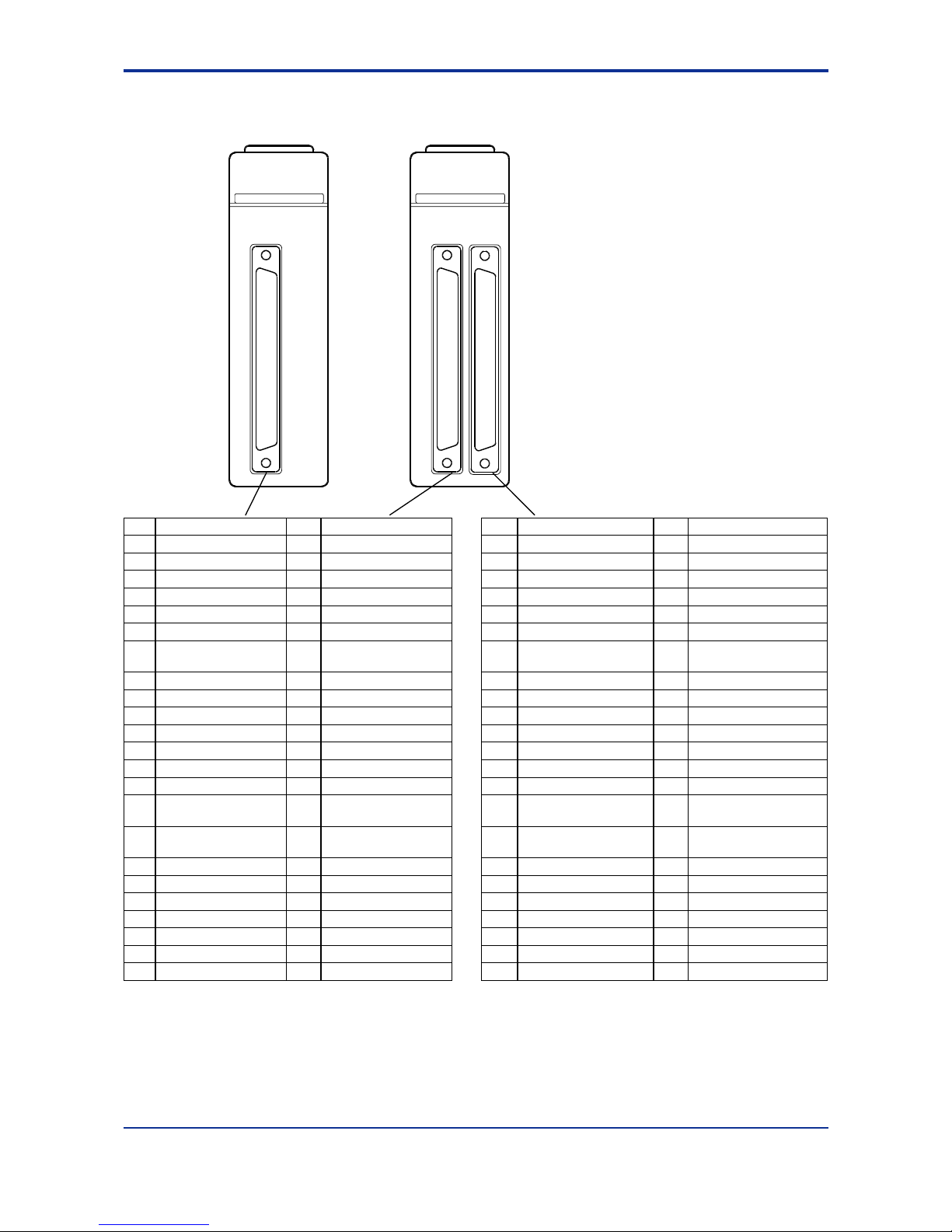
2.6 Terminal Assignments and Connections
24b Axis 4 Z-phase input (-) 24a Axis 2 Z-phase input (-) 24b Axis 8 Z-phase input (-) 24a Axis 6 Z-phase input (-)
23b Axis 4 Z-phase input (+) 23a Axis 2 Z-phase input (+) 23b Axis 8 Z-phase input (+) 23a Axis 6 Z-phase input (+)
22b Axis 4 pulse output A (+) 22a Axis 2 pulse output A (+) 22b Axis 8 pulse output A (+) 22a Axis 6 pulse output A (+)
21b Axis 4 pulse output A (-) 21a Axis 2 pulse output A (-) 21b Axis 8 pulse output A (-) 21a Axis 6 pulse output A (-)
20b Axis 4 pulse output B (+) 20a Axis 2 pulse output B (+) 20b Axis 8 pulse output B (+) 20a Axis 6 pulse output B (+)
19b Axis 4 pulse output B (-) 19a Axis 2 pulse output B (-) 19b Axis 8 pulse output B (-) 19a Axis 6 pulse output B (-)
18b Axis 4 deviation pulse clear 18a Axis 2 deviation pulse clear 18b Axis 8 deviation pulse clear 18a Axis 6 deviation pulse clear
17b Axis 4 deviation pulse clear
(GND)
17a Axis 2 deviation pulse clear
(GND)
17b Axis 8 deviation pulse clear
(GND)
17a Axis 6 deviation pulse clear
(GND)
16b Axis 3 Z-phase input (-) 16a Axis 1 Z-phase input (-) 16b Axis 7 Z-phase input (-) 16a Axis 5 Z-phase input (-)
15b Axis 3 Z-phase input (+) 15a Axis 1 Z-phase input (+) 15b Axis 7 Z-phase input (+) 15a Axis 5 Z-phase input (+)
14b Axis 3 pulse output A (+) 14a Axis 1 pulse output A (+) 14b Axis 7 pulse output A (+) 14a Axis 5 pulse output A (+)
13b Axis 3 pulse output A (-) 13a Axis 1 pulse output A (-) 13b Axis 7 pulse output A (-) 13a Axis 5 pulse output A (-)
12b Axis 3 pulse output B (+) 12a Axis 1 pulse output B (+) 12b Axis 7 pulse output B (+) 12a Axis 5 pulse output B (+)
11b Axis 3 pulse output B (-) 11a Axis 1 pulse output B (-) 11b Axis 7 pulse output B (-) 11a Axis 5 pulse output B (-)
10b Axis 3 deviation pulse clear 10a Axis 1 deviation pulse clear 10b Axis 7 deviation pulse clear 10a Axis 5 deviation pulse clear
9b Axis 3 deviation pulse clear
(GND)
9a Axis 1 deviation pulse clear
(GND)
9b Axis 7 deviation pulse clear
(GND)
9a Axis 5 deviation pulse clear
(GND)
8b External power 5 Vin 8a External power 5 Vin
(GND)
8b External power 5 Vin 8a External power 5 Vin (GND)
7b Axis 4 origin input 7a Axis 2 origin input 7b Axis 8 origin input 7a Axis 6 origin input
6b Axis 4 positive limit input 6a Axis 2 positive limit input 6b Axis 8 positive limit input 6a Axis 6 positive limit input
5b Axis 4 negative limit input 5a Axis 2 negative limit input 5b Axis 8 negative limit input 5a Axis 6 negative limit input
4b Axis 3 home position input 4a Axis 1 home position input 4b Axis 7 home position input 4a Axis 5 home position input
3b Axis 3 positive limit input 3a Axis 1 positive limit input 3b Axis 7 positive limit input 3a Axis 5 positive limit input
2b Axis 3 negative limit input 2a Axis 1 negative limit input 2b Axis 7 negative limit input 2a Axis 5 negative limit input
1b Contact input common 1a Contact input common 1b Contact input common 1a Contact input common
Pulse output A: Forward pulse output (in forward/reverse mode), or travel pulse output (in travel pulse/direction mode)
Pulse output B: Reverse pulse output (in forward/reverse mode), or direction output (in travel pulse/direction mode)
RDY
ERR
POSIT
YP14-0N
RDY
ERR
POSIT
YP18-0N
F020601.VSD
Page 20
2-5
IM 34M6H55-02E 1st Edition : Apr 1, 2002-00
Contact input common and the external power supply 5Vin/GND terminals are common
to all axes (they are connected through the internal circuitry even between different
connectors). Other signals are independent for each axis.
CAUTION
Always connect the external power supply (5 V DC) with the correct polarity. The internal
circuitry may be damaged otherwise.
For details on the external connection signals, please refer to Chapter 9, “External
Interface Signals.”
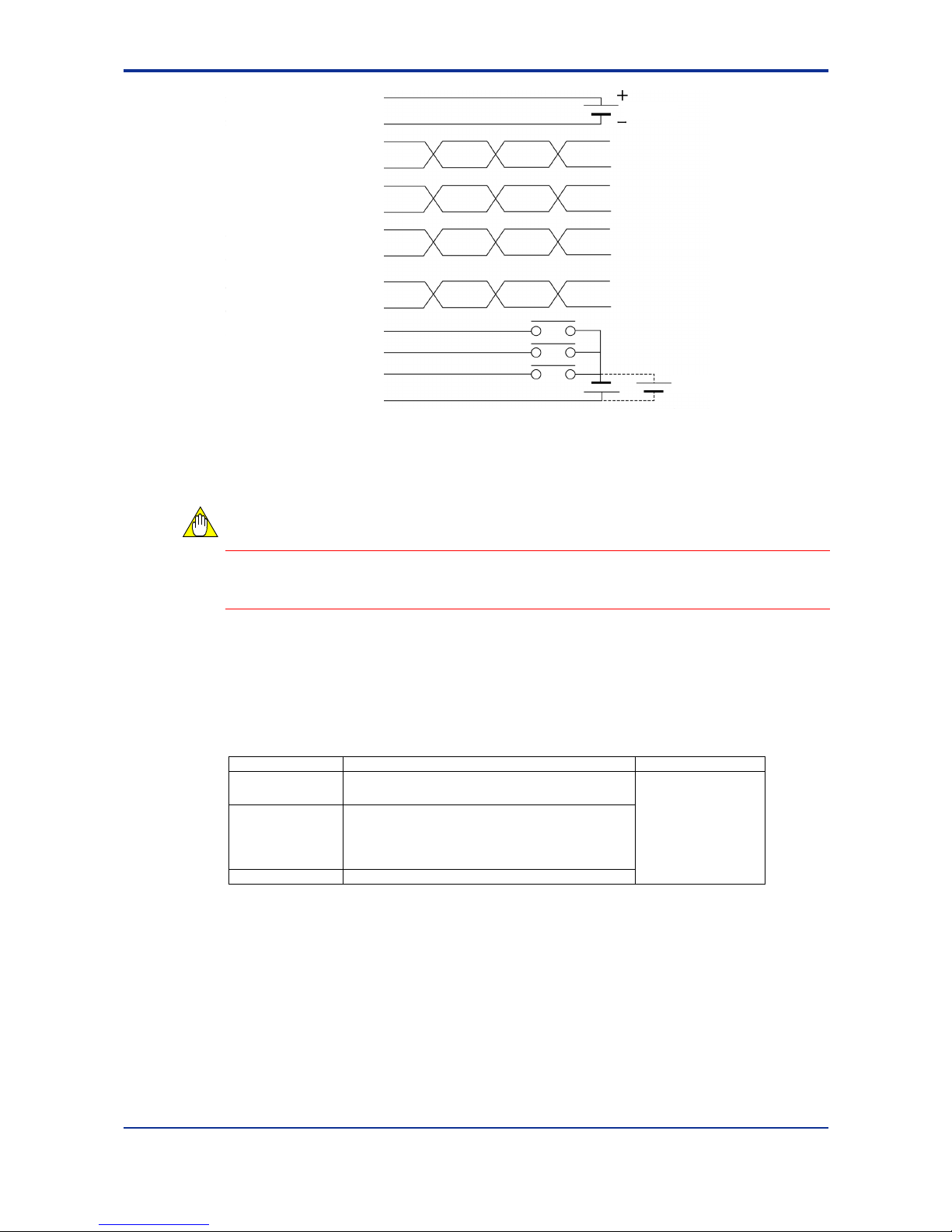
2.7 Applicable External Interface Connectors
Connection Applicable Connector Remarks
Soldered
FCN-361J048-AU connector
FCN-360C048-B connector cover (Fujitsu Limited)
Crimp-on
FCN-363J048 housing
FCN-363J-AU contacts
FCN-360C048-B connector cover (Fujitsu Limited)
Pressure-welded FCN-367J048-AU/F (Fujitsu Limited)
Purchase the
desired connector kit
separately.
External power 5Vin
External power 5Vin (GND)
Forward pulse -
Forward pulse +
Reverse pulse -
Reverse pulse +
Deviation pulse clear
Deviation pulse clear (GND)
Z-phase input -
z-phase input +
Origin input
Positive-direction limit input
Negative-direction limit input
Contact input common
5 V DC
24 V DC
Page 21
2-6
IM 34M6H55-02E 1st Edition : Apr 1, 2002-00
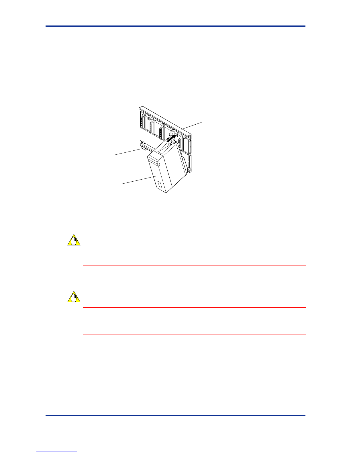
2.8 Attaching and Detaching Modules
TTTT Attaching/Detaching Modules
Figure 2.1 shows how to attach the module to the base module. First, hook the anchor
slot at the bottom of the module to be attached onto the anchor pin on the bottom of the
base module. Push the top of the module towards the base module until the yellow
button clicks into place.
Figure 2.1 Attaching/Detaching Modules
CAUTION
Always switch off the power before attaching or detaching a module.
CAUTION
Do not bend the connector pins on the rear of the module by force during the above
operation. If the module is pushed with improper force, the connector pins may bend
causing an error.
TTTT Detaching Modules
To remove the module from the base module, reverse the above operation:
Press the yellow button on the top of the module to unlock it, and tilt the module away
from the base module. Then lift the module off the anchor pin at the base.
Base module
This module
Anchor pin
29FG01.VSD
Page 22
2-7
IM 34M6H55-02E 1st Edition : Apr 1, 2002-00
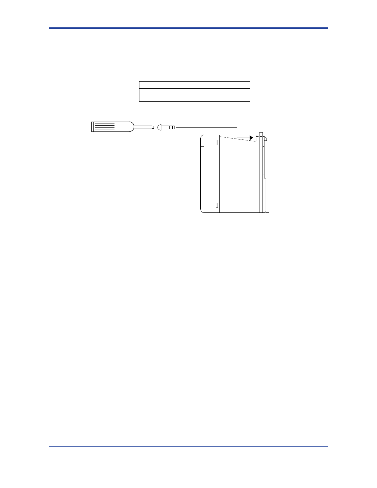
TTTT Attaching Module in Intense Vibration Environments
If the module is used in intense vibration environments, fasten the module with a screw
as described in the table below by screwing it into the threaded hole at the top of the
module with a Phillips screwdriver.
Screws to be used
M4 binder screws, 12-15 mm long
(or 14-15 mm long for screws with washer)
29FG02.VSD
Figure 2.2 Fastening the Module with a Screw
Page 23

Blank Page
Page 24

3-1
IM 34M6H55-02E 1st Edition : Apr 1, 2002-00
3. Function Overview
This chapter explains the major functions of the positioning modules. For details on
how to use each function, see Chapter 7. Table 3.1 summarizes the functions
discussed in this chapter.
Table 3.1 Major Functions
Function Description
Positioning operation Performs normal positioning.
Jog stepping
Allows a motor to be rotated manually, for example, during position
teaching.
Contact input
Inputs external contact signals such as a limit-switch signal or an origin
input signal.
Z-phase encoder input Inputs a Z-phase encoder signal during an origin search.
Normal origin search
operation
Searches for the origin using external contact inputs according to
commands issued from a program.
Automatic origin search
operation
Automatically searches for the origin using external contact inputs
according to the values stored in the entry parameters.
Deviation pulse clear signal
Outputs a deviation pulse clear signal when an origin position search is
completed.
Linear-interpolated operation Performs a multi-axial linear-interpolated operation.
Change in speed during
operation
Changes the speed during a positioning operation.
Change in target position
during operation
Changes the target position during a positioning operation.
Saving of entry parameters Saves the entry parameters in the flash memory.
Page 25
3-2
IM 34M6H55-02E 1st Edition : Apr 1, 2002-00
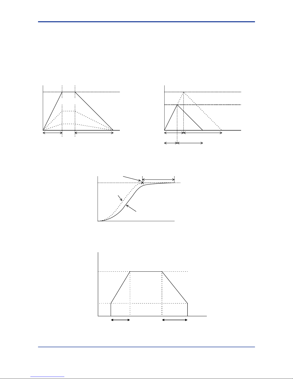
3.1 Positioning Operation
To initiate a positioning operation, write the target position, target speed, acceleration
time, and deceleration time from the CPU module, set the command code to 0, and
change the state of the Execute Command output relay from off to on. When the
positioning operation is completed, the End of Positioning input relay turns on. The
acceleration/deceleration curve is trapezoidal or of S-shape. The acceleration time and
deceleration time can be set independently.
Figure 3.1 Speed and Acceleration/deceleration Time for Trapezoidal/trigonometric Curves
Figure 3.2 Comparison Between the Theoretical and Actual Behaviors of a Servomotor in
Position Control
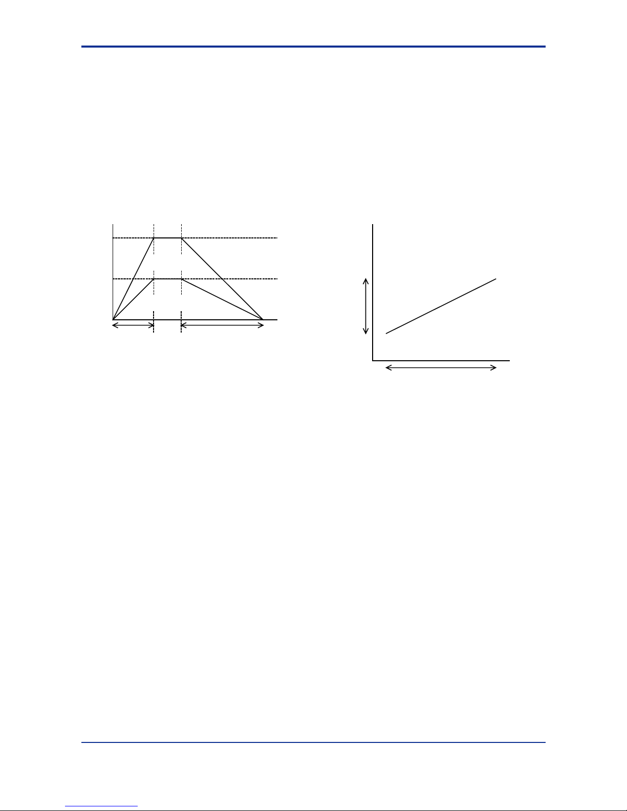
Figure 3.3 Acceleration/Deceleration Times when a Startup Speed Is Given
Time
Speed
Target speed
Acceleration time
Deceleration time
Travel
Target speed
Time
Speed
Acceleration
time
Deceleration time
Travel
Actual speed reached
Actual acceleration/
deceleration time
F030101.VSD
Time
Position
Position-reference
pulse count
Motor position
End of
positioning
Delay before target
position is reached
F030102.VSD
Startup speed
Target speed
Acceleration time Deceleration time
speed
Time
F030103.VSD
Page 26
3-3
IM 34M6H55-02E 1st Edition : Apr 1, 2002-00
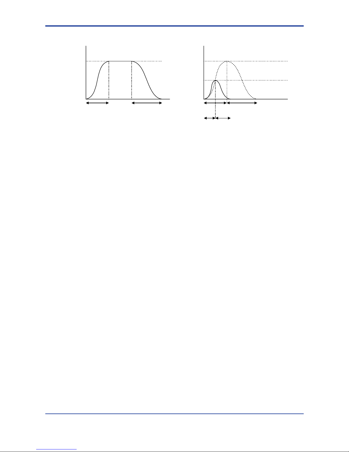
Figure 3.4 Acceleration/Deceleration Times when Using S-shape Acceleration/Deceleration
Target
speed
Acceleration time Deceleration time
Speed
Time
Target speed
Acceleration time Deceleration time
Speed
Time
Actual acceleration/
deceleration time
Actual speed reached
F030104.VSD
Page 27
3-4
IM 34M6H55-02E 1st Edition : Apr 1, 2002-00
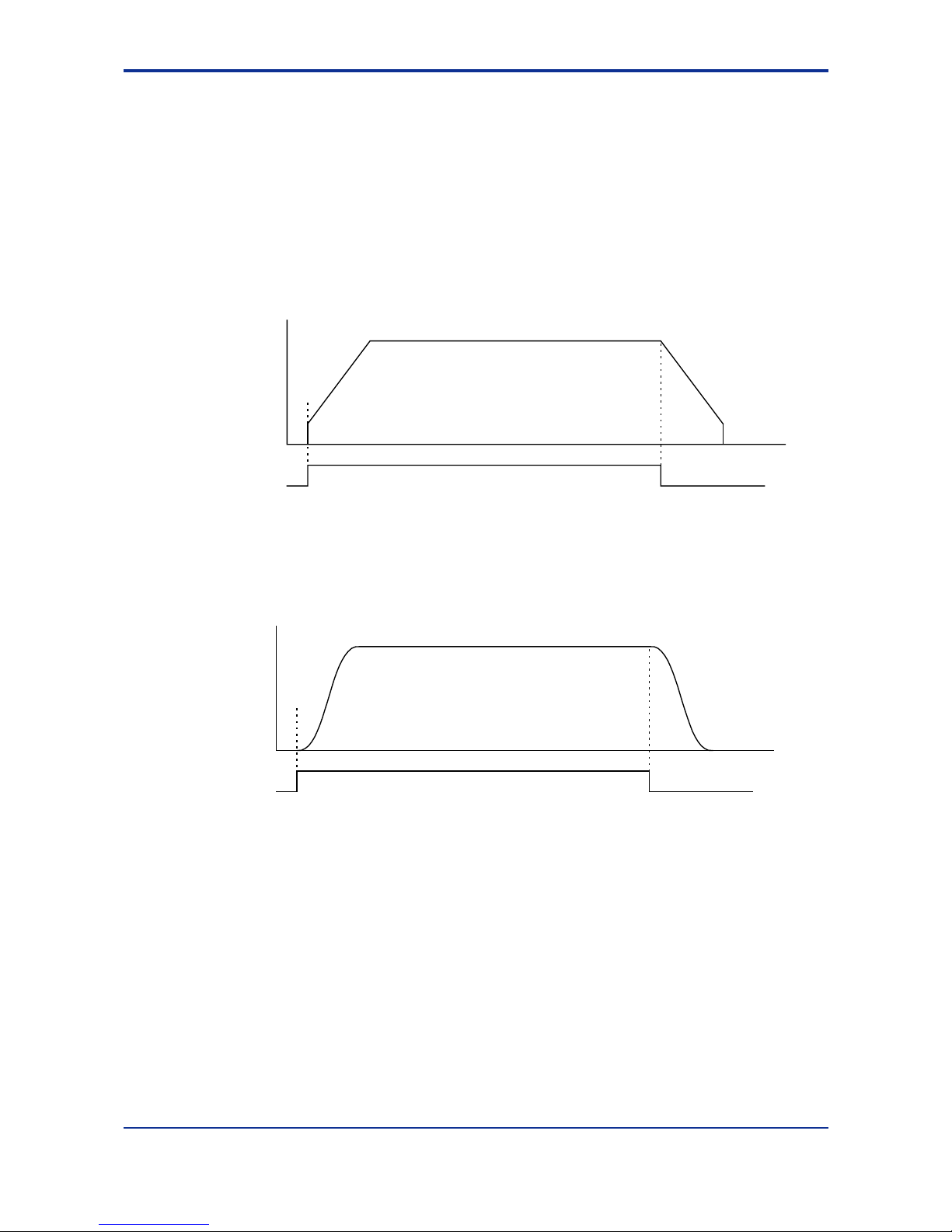
3.2 Jog Stepping
To perform jog stepping, first write the target velocity, acceleration time, deceleration
time and other required parameters from the CPU module, and then change the state of
the Positive-direction Jog Stepping output relay or Negative-direction Jog Stepping
output relay from off to on. To stop job stepping, turn off the corresponding output relay.
During jog stepping, any error in the positive-direction or negative-direction limit value
will not be detected (no error occurs). If the operation range of the positioning module is
exceeded, however, a pulse overflow error occurs.
The acceleration/deceleration curve can be either trapezoidal or of S-shape, and the
acceleration and deceleration times can be set independently.
Figure 3.5 Jog-stepping Operation (Positive Direction, Trapezoidal Acceleration/deceleration)
Figure 3.6 Jog-stepping Operation (Positive Direction, S-shape Acceleration/deceleration)
Speed
Time
Positive-direction
jog stepping
Start
End
F030201.VSD
Speed
Time
Positive-direction jog
stepping
Start
End
F030202.VSD
Page 28

3-5
IM 34M6H55-02E 1st Edition : Apr 1, 2002-00
3.3 Contact Inputs
The positioning module has three external contact inputs defined as “Positive-direction
limit,” “Negative-direction limit,” and “Origin” for each axis. You can read the state of
each contact input using an application program.
You can set the polarity of each contact input separately.
3.4 Z-phase Encoder Input
For improved repeatability in origin searches, you can use a Z-phase encoder input.
You can read the state of the encoder input in the same way you read the state of a
contact input.
3.5 Origin Search
There are two ways to perform origin search: normal and automatic. In normal origin
search, the origin search behavior is arbitrarily defined by an application program; the
automatic origin search operation uses entry parameters to define the origin search
behavior. In either type of operation, only trapezoidal acceleration or deceleration is
available. This section describes the normal origin search operation only.
To start an origin search, write the speed set point, the direction of the origin search, the
origin search mode (operation upon detecting external contact inputs), Z-phase edge
selection and other required parameters, set the command code to 2 and change the
state of the Execute Command output relay from off to on. When the positioning module
detects a change in the state of a preset external contact input after the start of the
origin-search operation, the module either stops the motor or performs Z-phase
detection, depending on the value of the origin search mode.
In Z-phase detection, when the module detects the preset Z-phase pulse count, it
immediately stops the motor. The position where the motor stops is defined as the origin
(position “0”). At that point, it outputs the deviation pulse clear signal for a period
specified in the deviation pulse clear time parameter. If the Z-phase pulse count is set to
0, it does not output the deviation pulse clear signal.
To perform an origin search at two different speeds or to change the operation direction
according to the state of an external contact input detected during an origin search, split
the origin search process into different phases, varying the parameters for each phase.
This strategy allows you to customize your origin-search operation to a desired search
pattern.
See the next page for information on the origin search mode.
Page 29
3-6
IM 34M6H55-02E 1st Edition : Apr 1, 2002-00
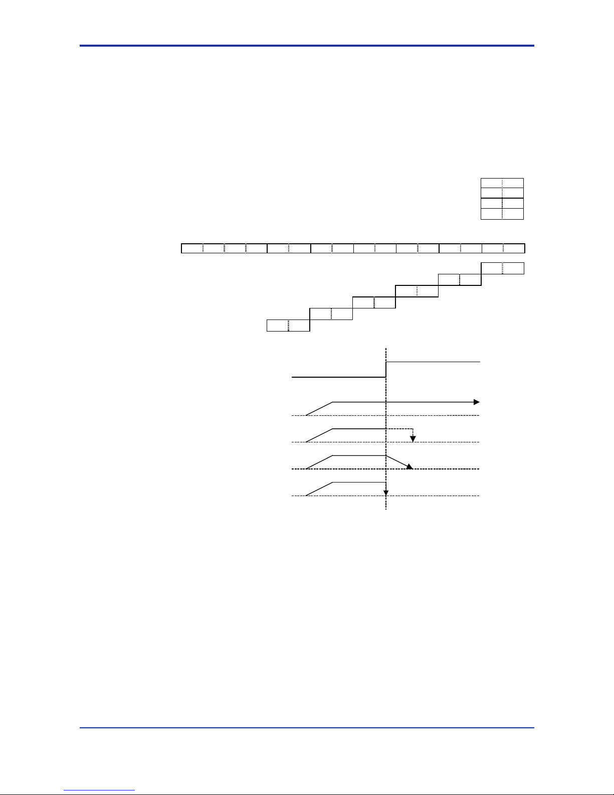
zzzz Details on Origin Search Mode
The origin search mode defines the operation when an edge is detected in each contact
input using bit combinations.
One out of four 2-bit combinations can be selected for each rising/falling edge of an
external contact input.
Bits 12 to 15 are fixed to 0.
If all bits are 0, the operation shifts to a Z-phase search after the start of the origin
search.
0 0
0 1
1 0
Ignore (Stop with error at the rising edge of the limit input in the direction of operation)
Shift to Z-phase search
Decelerate and stop
Stop immediately
1 1
15 14 13 12 11 10 9 8 7 6 5 4 3 2 1 0
0 0 0 0 NU1 NU0 ND1 ND0 PU1 PU0 PD1 PD0 OU1 OU0 OD1 OD0
Fall in origin input ←--------------------
OD1 OD0
Rise in origin input ←---------------
OU1 OU0
Fall in positive-direction limit input ←------
PD1 PD0
Rise in positive-direction limit input ←-
PU1 PU0
ND1 ND0
-→Fall in negative-direction limit input
NU1 NU0
-----→Rise in negative-direction limit input
Figure 3.7 Origin Search Operation
For a rise in contact input
When "ignore" is specified
When "shift to Z-phase
search" is specified
When "decelerate and stop"
is specified
When "stop im mediately"
is specified
Stop when z-phase
is detected
F030203.VSD
Page 30

3-7
IM 34M6H55-02E 1st Edition : Apr 1, 2002-00
3.6 Automatic Origin Search
There are two ways to perform origin search: normal and automatic. In normal origin
search, the origin search behavior is arbitrarily defined by an application program; the
automatic origin search operation uses entry parameters to define the origin search
behavior. In either type of operation, only trapezoidal acceleration or deceleration is
available. This section describes the automatic origin search operation only.
Before initiating the automatic origin search, you must first set the automatic origin
search mode and other entry parameters for automatic origin search. To initiate the
automatic origin search, set the command code to 8 (Automatic Origin Search
command), and change the state of the Execute Command output relay from off to on.
A series of origin search movements will be automatically carried out up to Z-phase
detection according to the entry parameter settings. In Z-phase detection, when the
number of Z-phase pulses as defined in the Automatic Origin Search Z-phase Pulse
Count parameter is detected, the axis stops immediately. The stop position is defined as
the origin (the value of the origin is defined in the Automatic Origin Search Origin Offset
parameter). The deviation pulse clear signal is then output for a period specified in the
Automatic Origin Search Deviation Pulse Clear Time parameter. The automatic origin
search has two modes: mode 0 and mode 1. Mode 0 uses the origin switch input, whilst
mode 1 does not use the origin switch input but uses the positive/negative direction limit
switch input instead.
Figure 3.8 illustrates the automatic origin search behaviors initiated at different start
positions where the automatic origin search mode is set to 0 (mode 0, using the origin
switch), and the automatic origin search direction is set to 0 (negative direction). If the
automatic origin search direction is set to 1 (positive direction), exchange the positive
direction limit and the negative direction limit as shown in Figure 3.8.
1. At the start of automatic origin search, if the origin switch or the negative direction
limit switch is off (not reached), the axis moves at automatic origin search speed 1
in the negative direction. If the origin switch or the negative direction limit switch is
on (reached) at the start of automatic origin search, automatic origin search starts
with step 3 below.
2. The axis decelerates and stops at the rising edge of the origin or negative direction
limit switch.
3. The axis then restarts in the positive direction at automatic origin search speed 2.
4. The axis shifts into the Z-phase detection operation at the falling edge of the origin
switch.
zzzz If the axis is on the positive direction side of the origin switch at origin
search start
Positive-direction limit
Nagative-direction limitOrigin
Startup speed
Search speed 1
Search speed 2
Z-phase pulse
F030601.VSD
Page 31

3-8
IM 34M6H55-02E 1st Edition : Apr 1, 2002-00
zzzz If the axis is right on the origin switch (with the origin switch input on)
at origin search start
zzzz If the axis is between the origin and the negative limit switch at origin
search start
z
zz
z If the axis is right on the negative limit switch at origin search start
Figure 3.8 Automatic Origin Search Behaviors (mode 0, negative direction search)
Figure 3.9 illustrates the automatic origin search behaviors initiated at different start
positions where the automatic origin search mode is set to 1 (mode 1, not using the
origin switch), and the automatic origin search direction is set to 0 (negative direction). If
the automatic origin search direction is set to 1 (positive direction), exchange the
positive direction limit and the negative direction limit as shown in Figure 3.9.
1. At the start of automatic origin search, if the negative direction limit switch is off (not
reached), the axis moves at automatic origin search speed 1 in the negative
direction. If the negative direction limit switch is on (reached) at the start of
automatic origin search, automatic origin search starts with step 3 below.
2. The axis decelerates and stops at the rising edge of the negative direction limit
switch.
3. The axis then restarts in the positive direction at automatic origin search speed 2.
4. The axis shifts into the Z-phase detection operation at the falling edge of the
negative limit switch.
Positive-direction limit Negative-direction limitOrigin
Startup speed
Search speed 1
Search speed 2
Z-phase pulse
F030603.vsd
Positive-direction limit Negative-direction limitOrigin
Startup speed
Search speed 2
Z-phasse pulse
F030602.VSD
Positive-direction limit Negative-direction limitOrigin
Startup speed
Search speed 2
Z-phase pulse
F030604.VSD
Page 32

3-9
IM 34M6H55-02E 1st Edition : Apr 1, 2002-00
zzzz If the axis is away from the negative limit switch at origin search start
zzzz If the axis is right on the negative limit switch at origin search start
Figure 3.9 Automatic Origin Search Behaviors (mode 1, negative direction search)
Positive-direction limit Negative-direction limit
Startup speed
Search speed 2
Z-phase pulse
F030606.vsd
F030605.vsd
Positive-direction limit Negative-direction limit
Startup speed
Search speed 1
Search speed 2
Z-phase pulse
Page 33

3-10
IM 34M6H55-02E 1st Edition : Apr 1, 2002-00
3.7 Deviation Pulse Clear Signal Output
In an origin search using a servo driver, this outputs a deviation pulse clear signal at the
end of the origin search to the servo driver. The deviation pulse clear signal is
connected to the input of the servo driver.
The length of the deviation pulse clear signal output is defined in a parameter.
When the Z-phase pulse count is set to 0, no deviation pulse clear signal is generated.
Figure 3.10 Deviation Pulse Clear Signal Output
Search speed 2
Z-phase pulse
Deviation pulse clear
Deviation pulse clear time
Origin input
F030701.VSD
Page 34
3-11
IM 34M6H55-02E 1st Edition : Apr 1, 2002-00
3.8 Linear-Interpolated Operation
To perform a linear-interpolated operation, write the target speed, target position,
acceleration time, deceleration time and other necessary parameters for each axis from
the CPU module, set the command code to “0”, and change the state of the Execute
Command output relay from off to on for all axes simultaneously. When the positioning
operation for each axis is completed, the input relay End-of-Positioning input relay for
each axis turns on.
In this operation, set the same acceleration and deceleration times to all axes
concerned. Set the startup speed for all axes to 0 and then calculate and set the ratio
between the target speeds of the two axes so that it equals the ratio between the travels
of the two axes.
Figure 3.11 Multi-axial Linear-interpolated Operation (Example of Biaxial Operation)
Time
Speed
X-axis target speed
Acceleration time
Deceleration time
X-axis travel
X-axis
Y-axis
X-axis travel
Y-axis
travel
Y-axis travel
Y-axis target speed
F030801.VSD
Page 35

3-12
IM 34M6H55-02E 1st Edition : Apr 1, 2002-00
3.9 Changing Speed during Operation
To change the speed of an axis currently moving in a positioning or jog stepping
operation, write a new target speed and acceleration/deceleration time, set the
command code to 6 (Change Speed command), and change the state of the Execute
Command output relay from off to on.
The following restrictions apply to changing the speed during positioning or jog stepping.
If the Change Speed command issued during acceleration, deceleration or a change in
speed is such as to prevent the axis from stopping at the target position, the command
is ignored, the Execute Command ACK input relay is not set, and an alarm is raised.
The alarm status is automatically cleared when the state of the Execute Command
output relay is changed from on to off.
If a Change Speed command is issued during a jog stepping operation, the module
waits until all acceleration and deceleration has been completed before executing the
command. If a new Change Speed command is issued during the wait, the previous
command is discarded and only the new command is executed.
Figure 3.12 Behavior When the Speed is Changed
Time
Speed
Start
↑↑ ↑
Request to
change speed
Request to
change speed
F030901.VSD
Page 36

3-13
IM 34M6H55-02E 1st Edition : Apr 1, 2002-00
3.10 Changing Target Position during Positioning
To change the target position during positioning, write a new target position, set the
command code to 7 (Change Target Position command), and change the state of the
Execute Command output relay from off to on. A new target position issued during
positioning may require a reversal of the direction of a moving axis. In this case, the
axis immediately decelerates and stops, and then accelerates in the other direction
toward the new target position.
If a Change Target Position command is issued in the End-of-Positioning status, the
command is executed just as the Start Positioning command.
The following restrictions apply to the change in target position during positioning.
If a Change Target Position command is issued during acceleration/deceleration or a
change in speed, the execution of the command is suspended until the start of the
constant-speed operation or until the axis stops. During the execution of the Change
Target Position command, only the Decelerate-and-Stop and Stop Immediately
commands are available. The extended status indicates whether the Change Target
Position command is in execution. If an invalid command is issued when the Change
Target Position command is being executed, an alarm is raised. The alarm is
automatically cleared when the state of the Execute Command output relay is changed
from on to off. The Change Target Position command does not allow a change in the
target speed, acceleration or deceleration.
Figure 3.13 Behavior When the Target Position is Changed
Time
Speed
Start↑
↑
Request to
change target position
Time
Speed
Start↑
Request to
change target position
↑
Axis moving direction unchanged Axis moving direction reversed
F031001.VSD
Page 37

3-14
IM 34M6H55-02E 1st Edition : Apr 1, 2002-00
3.11 Saving Entry Parameters
When all axes are at rest, you can save entry parameters in the flash memory. Entry
parameters must be set for all axes with the Set Parameter command before you can
save the parameters in the flash memory. You can issue the Save Parameter command
for a particular axis. When you do so, however, the entry parameters of all axes are
saved in the flash memory.
To save entry parameters in the flash memory, set the command code to 9 (Save
Parameter command), and change the state of the Execute Command output relay from
off to on.
At power up or system reset, the content of the flash memory is automatically reloaded
to the entry parameters.
To initialize the content of the flash memory to the factory defaults, set the command
code to 99 (Initialize Flash Memory command), and change the state of the Execute
Command output relay from off to on. At this time, the entry parameters will also be
initialized to the factory defaults.
CAUTION
- If the power to the positioning module is cut off during the execution of the Save
Parameter command, the content of the entry parameters being saved will be lost.
- As there is a limit to the number of times data can be written to the flash memory
(100,000 times max.), you should save entry parameters to the flash memory only
when required.
Page 38

4-1
IM 34M6H55-02E 1st Edition : Apr 1, 2002-00
4. Parameters
4.1 Parameters
Of the parameters given Tables 4.2 and 4.3, those listed with two data position numbers
are 2 word data. The smaller data position number contains the low-order word, and the
larger data position number contains the high-order word.
Data position numbers are three-digit numbers; the leading * symbol represents the
value (axis number - 1), ranging from 0 for axis 1 to 7 for axis 8.
Each data position numbers corresponds to a word. Use only READ and WRITE
instructions on a word-basis when accessing from a sequence program. Using
long-word-based instructions may cause unexpected results. You should also use
word-based instructions when accessing from BASIC programs.
zzzz Fixed-point data
Speed-related data whose unit is [(1/65536) pulses/ms] are fixed point data with 1-word
for the integer part (16 bits) and 1-word for the fractional part (16 bits). Again, the smaller
data position number contains the low-order word, and the larger data position number
contains the high-order word.
Bits for the integer part of the binary data designate the values for 1, 2, 4 ... whilst bits
for the fractional part designate the values for 1/2, 1/4, 1/8, etc. If the integer and the
fractional parts consist of 16 bits each, the least significant bit in the fractional part
represents 1/65536, which means that the data is 32-bit (long-word) with a unit of
1/65536. Negative numbers are expressed as complements of 2, like regular binary
data.
Table 4.1
Bit 31(MSB) 30 O O O 17 16 15 14 O O O 1 0(LSB)
Value Sign bit 16384 O O O 2 1 1/2 1/4 O O O 1/32768 1/65536
High-order word Low-order word
– Example of fixed point data
When setting speed data of 123.45 [pulse/ms] (=123450 [pulses/s]),
123.45 x 65536 = 8090419.2 [(1/65536) pulses/ms]. Thus, we should set 8090419
as long-word data. The high-order word of this data is 123 because
8090419 ÷ 65536 = 123. The low-order word is the remainder, i.e., 29491.
zzzz Sample program for converting speed data
Here, we show a sample sequence program for converting speed data in [pulses/s] into
setting data for the positioning module with unit [(1/65536) pulses/ms].
Let D0001 (long-word data) be the original data ([pulses/s]).
(1) Divide D0001 by 1000 (long-word division) and store the result in D0011. In this
case, since the maximum value of D0001 is 3998000 (3.998 Mpps) and it is
positive, the maximum value of the result is 3998 and the high-order word (D0012)
is always 0. The low-order word of the result of the division (D0011) will become the
high-order word (the integer which is 16 bits long) of the value ([(1/65536)
pulses/ms]) to be set in the positioning module.
Page 39

4-2
IM 34M6H55-02E 1st Edition : Apr 1, 2002-00
Store the remainder in D0013 (the low-order word) and D0014 (the high-order
word). Since the divisor is 1000, the maximum value of the remainder is 999 and
the high-order word of the remainder (D0014) is always 0.
Computation result
D00014 D00013 D00012 D00011
0 Remainder 0 High-order setting data
(2) Multiply the remainder by 65536 and divide it again by 1000. A useful tip: the
remainder is in D0013 and D0012 is always 0; thus, if we treat D0012 as a longword data (high-order word in D0012 and low-order word in D0013), its value is
already the result of multiplying the remainder by 65536. Therefore, in order to
multiplying the remainder by 65536 and then divide it again by 1000, we only need
to divide D0012 by 1000 (long-word division). Store the result of this division into
D0021.
D0012 (long word) has a maximum value of 999 × 65536; dividing by 1000 gives
65470 maximum so the high-order word (D0022) is always 0. Thus, D0021 is the
low-order word (16-bit fractional part) of the data [(1/65536) pulses/ms] to be set in
the positioning module and the remainder is discarded.
Computation result
D00024 D00023 D00022 D00021
0 Remainder 0 Low-order setting data
(3) Combine the contents of D0011 and D0021 into long-word data ([(1/65536)
pulses/ms]). To do this, you need to perform long-word division twice and transfer
the resulting high-order and low-order words to D0032 and D0031, respectively.
D0011-D0014 and D0021-D0024 are work areas.
Computation result
D00032 D00031
High-order setting data Low-order setting data
In the case of 123450 [pulse/s]
D00011
=
D00001
/
1000
L
MOV D00011 D00032
MOV D00021 D00031
D00021
=
D00012
/
1000
L
Page 40

4-3
IM 34M6H55-02E 1st Edition : Apr 1, 2002-00
In the case of 123450 [pulse/s]
(1) D0011 = 123450/1000 (long-word division)
D00014 D00013 D00012 D00011
0 450 0 123
29491200 (=450×65536)
(2) D0021 = 29491200/1000 (long-word division)
D00024 D00023 D00022 D00021
0 200 0 29491
From the results, the high-order word of the long-word data ([(1/65536) pulses/ms]) to
be set in the positioning module is 123, and the low-order word is 29491.
Page 41

4-4
IM 34M6H55-02E 1st Edition : Apr 1, 2002-00
4.1.1 Entry Parameters
At power up or system reset, the content of the flash memory is automatically reloaded
to the entry parameters. To change the settings of the entry parameters, write new
parameter settings from the CPU module, and execute the Set Parameter command.
Table 4.2 Entry parameters
Data Position
Number
Parameter Range of values
*01 Maximum Speed Selection 0: 499,750 [pps], 1: 3,998,000 [pps]
*02 Pulse Output Mode
0: Forward/reverse pulse output
1: Travel pulse/direction output
*03 Direction of Rotation
0: Positive data indicates forward pulse output.
1: Negative data indicates forward pulse output.
*04 Contact Input Polarity 0 to 7
*05/*06 Positive-direction Limit -2147483648 to 2147483647 [pulses]
*07/*08 Negative-direction Limit
-2147483648 to (positive-direction limit value - 1)
[pulses]
*09/*10 Speed Limit
1 to 32751616 [(1/65536) pulse/ms] if maximum
speed selection is 0
1 to 262012928 [(1/65536) pulse/ms] if maximum
speed selection is 1
*11
Automatic Origin Search
Mode
0: Use origin input
1: Do not use origin input
*12
Automatic Origin Search
Direction
0: Negative direction, 1: Positive direction
*13/*14
Automatic Origin Search
Speed 1
1 to speed limit value
*15/*16
Automatic Origin Search
Speed 2
1 to automatic origin search speed 1
*17/*18
Automatic Origin Search
Starting Speed
0 to automatic origin search speed 2
*19
Automatic Origin Search
Acceleration Time
0 to 32767 [ms]
*20
Automatic Origin Search
deceleration Time
0 to 32767 [ms]
*21
Automatic Origin Search
Z-phase Edge Selection
0: Rising edge, 1: Falling edge
*22
Automatic Origin Search
Z-phase Search Count
0 to 32767 [times]
*23/*24
Automatic Origin Search
Z-phase Search Range
0 to 2147483647/automatic origin search Z-phase
pulse count [pulses]
*25
Automatic Origin Search
Deviation Pulse Clear Time
0 to 32767 [ms]
*26/*27
Automatic Origin Search
Origin Offset Value
-2147483648 to 2147483647 [pulses]
The symbol
‘*’ designates the value of (axis number - 1). The values for axis 1 to axis 8 are 0 to 7 respectively.
Page 42

4-5
IM 34M6H55-02E 1st Edition : Apr 1, 2002-00
4.1.2 Command Parameters
These are parameters to be set when executing a command. It is necessary to write all
the required parameters when executing a command.
Table 4.3 Command Parameters
Data Position
Number
Parameter Range of values
*41 Command Code 0 to 9, and 99
*42 Target Position Mode 0: Absolute position, 1: Relative position
*43/*44 Target Position Negative-direction limit value to positive-direction limit
value [pulses]
*45 Acceleration/deceleration
Mode
0: Trapezoidal curve (with programmable startup
speed), 1: S-shape curve
*46/*47 Target Speed 1 to speed limit [(1/65536) pulses/ms]
*48 Acceleration Time 0 to 32767 [ms]
*49 Deceleration Time 0 to 32767 [ms]
*50/*51 Startup Speed 0 to target speed [(1/65536) pulses/ms]
(valid only for trapezoidal acceleration/deceleration)
*52 Origin Search Mode 0 to 4095
*53 Origin Search Direction 0: Negative direction, 1: Positive direction
*54 Z-phase Edge Selection 0: Rising edge, 1: Falling edge
*55 Z-phase Search Count 0 to 32767 [times]
*56/*57 Z-phase Search Range 0 to 2147483647/Z-phase search count [pulses]
*58 Deviation Pulse Clear Time 0 to 32767 [ms]
The symbol
‘*’ designates the value of (axis number - 1). The values for axis 1 to axis 8 are 0 to 7 respectively.
Page 43

4-6
IM 34M6H55-02E 1st Edition : Apr 1, 2002-00
4.2 Required Parameters for Each Command
You must write all the required parameters before executing a command for the
positioning module from the CPU module. Table 4.4 shows the required parameters for
each command.
The Set Parameter command and the Save Parameter command that respectively
updates and saves all the entry parameters are not shown in the table.
Table 4.4 Parameters Required for Each Command
Command
Data
Position
Number
Parameter
Start Positioning
Normal Origin Search
Positive- or Negative-
Direction Jog Stepping
Set Current Position
Change Speed
Change Target Position
Decelerate & Stop
Stop Immediately
Reset Error
Automatic Origin Search
*41 Command code ◎ ◎ – ◎ ◎ ◎ ◎ – ◎ ◎
*42 Target position mode ◎ – – – – ◎ – – – –
*43/*44 Target position ◎ – – ◎ – ◎ – – – –
*45 Acceleration/deceleration
mode
◎ – ◎ – – △ – – – –
*46/*47 Target speed ◎ ◎ ◎ – ◎ △ – – – –
*48 Acceleration time ◎ ◎ ◎ – ◎ △ – – – –
*49 Deceleration time ◎ ◎ ◎ – ◎ △ – – – –
*50/*51 Starting speed ○ ◎ ○ – – △ – – – –
*52 Origin search mode – ◎ – – – – – – – –
*53 Origin search direction – ◎ – – – – – – – –
*54 Z–––– phase edge selection – ○ – – – – – – – –
*55 Z–––– phase search count – ○ – – – – – – – –
*56/*57 Z–––– phase search range – ○ – – – – – – – –
*58 Deviation pulse clear time – ○ – – – – – – – –
The symbol
‘*’ designates the value of (axis number - 1). The values for axis 1 to axis 8 are 0 to 7 respectively.
◎ : Mandatory parameters.
○ : Parameters that are mandatory or optional depending on the values of other parameters.
△ : Mandatory if the command is to be executed in the End of Positioning Status.
– : Not used (have no effect on the operation of the commands if used).
Page 44

4-7
IM 34M6H55-02E 1st Edition : Apr 1, 2002-00
4.3 Description of Parameters
4.3.1 Entry parameters
At power up, the content of the flash memory is automatically reloaded to the entry
parameters. Modify the values of the entry parameters as necessary using the Set
Parameter command in an application program. If a parameter value is invalid, the Error
Notification input relay is set, and an entry parameter setting error results. When this
happens, all commands other than the Set Parameter command are disabled. Execute
the Set Parameter command again with valid values. To save the values of the entry
parameters in flash memory, use the Save Parameter command.
Table 4.5 Entry Parameters
Parameter Type
(Data Position
Number)
Description Data Range Remarks
Maximum Speed
Selection (*01)
Sets the maximum
speed of output pulses.
0: 499,750 [pps]
1: 3,998,000 [pps]
[Default: 0]
Set to 0 for pulse motors or 1 for
servomotors. If 1 is selected for pulse
motors, the performance is not
guaranteed. If the maximum speed of
a servomotor used is not more than
499,750 pps, select 0.
Pulse Output
Mode (*02)
Sets the pulse output
mode.
0: Forward/reverse pulse output
1: Direction/travel pulse output
[Default: 0]
Direction of
Rotation (*03)
Sets the relationship
between
positive/negative position
data from the CPU
module and the
forward/reverse pulse
output.
0: Positive value indicates
forward pulse output.
1: Negative value indicates
forward pulse output.
[Default: 0]
Position and negative data here refers
to positioning parameter values set by
a program from the CPU module.
Contact Input
Polarity (*04)
Defines the logic of the
external contact inputs.
Specified for each contact input as
a bit. “0” indicates an “a” contact,
and “1” indicates a “b” contact.
Bit 0: Negative-direction limit
input
Bit 1: Positive-direction limit input
Bit 2: Origin position input
[Default: 0]
An “a” contact input is an input which
is true when a signal input exists, and
a “b” contact input is an input which is
true when no signal input exists. For
example, a “b” contact limit input is
detected when there is no limit signal
and false when there is a limit signal.
Positive-direction
Limit (*05/*06)
Sets the operation limit
position in the positive
direction as the number
of pulses from the origin.
-2147483648 to 2147483647
[pulses]
[Default: 2147483647]
Negative-direction
Limit (*07/*08)
Sets the operation limit
position in the negative
direction as the number
of pulses from the origin.
-2147483648 to (positive-direction
limit value – 1) [pulses]
[Default: -2147483648]
If the origin search is not used, the
current position at power up is used as
the origin. If you start the system after
setting a target position beyond this
range, an error results and the motor
does not start. During an origin search
or jog stepping operation, these limit
values are disregarded (no error
occurs).
Speed Limit
(*09/*10)
Sets the speed setting
range.
1 to 32751616 [(1/65536)
pulse/ms] if maximum speed
selection is 0
1 to 262012928 [(1/65536)
pulse/ms] if maximum speed
selection is 1
[Default:
32751616 (= 499750 pps)]
If a command is given with the target
speed beyond this value, an error
occurs.
The symbol
‘*’ designates the value of (axis number - 1). The values for axis 1 to axis 8 are 0 to 7 respectively.
(Continued on the next page)
Page 45

4-8
IM 34M6H55-02E 1st Edition : Apr 1, 2002-00
Parameter Type
(Data Position
Number)
Description Data Range Remarks
Automatic Origin
Search Mode
(*11)
Specifies whether the
origin input is used for
automatic origin search.
0: Origin input is used.
1: Origin input is not used.
[Default: 0]
For details, refer to Section 3.5, “Origin
Search.”
Automatic Origin
Search Direction
(*12)
Sets the direction of
movement for speed 1
during automatic origin
search.
0: Negative direction
1: Positive direction
[Default: 0]
Automatic Origin
Search Speed 1
(“13/*14)
Sets the high search
speed for automatic
origin search.
1 to speed limit value
[Default: 655360 (10000 pps)]
Automatic Origin
Search Speed 2
(“15/*16)
Sets the low search
speed for automatic
origin search.
1 to automatic origin search
speed 1
[Default: 65536 (1000 pps)]
Automatic Origin
Search Starting
Speed (*17/*18)
This is the starting speed
at the beginning of, and
the speed just before
stopping at the end of,
automatic origin search.
0 to automatic origin search
speed 2
[Default: 0]
When the positioning module is used to
control a pulse motor, if this speed is set
to 0, the motor could resonate and get out
of phase in the early stage of acceleration
(or in the late stage of deceleration). Thus
this speed should be set above the
resonance frequency. Also, if this speed
is set too high, the motor undergoes
mechanical shock and could get out of
phase at starting or stopping. When the
positioning module is used to control a
servomotor, this speed is normally set to
0.
Automatic Origin
Search
Acceleration Time
(*19)
Sets the time it takes to
reach search speed 1
from the starting speed
during automatic origin
search.
0 to 32767 [ms]
[Default: 1000]
The acceleration to search speed 2 during
automatic origin search is done at the
same acceleration rate as for the
acceleration to search speed 1.
Automatic Origin
Search
Deceleration Time
(*20)
Sets the time it takes to
decelerate from search
speed 1 to a halt during
automatic origin search.
0 to 32767 [ms]
[Default: 1000]
The deceleration from search speed 2
during automatic origin search is done at
the same deceleration rate as for the
deceleration from search speed 1.
Automatic Origin
Search Z-phase
Edge Selection
(*21)
Specifies whether to use
the rising edge or the
falling edge of a Z-phase
pulse for Z-phase
detection during an
automatic origin search.
0: Rising edge
1: Falling edge
[Default: 0]
Automatic Origin
Search Z-phase
Pulse Count (*22)
Specifies how many Zphase pulses must be
detected before an origin
can be found during
automatic origin search.
0 to 32767 [pulses]
[Default: 0]
Automatic Origin
Search Z-phase
Search Range
(*23/*24)
An error occurs if a Zphase cannot be
detected within this pulse
count range during
automatic origin search.
0 to 2147483647/automatic
origin search Z-phase pulse
count [pulses]
[Default: 2147483647]
This parameter is used to prevent
continued operation when no Z-phase can
be detected because of a disconnected Z-
phase signal line, etc. This value is
usually set close to the period of the Z-
phase.
Automatic Origin
Search Deviation
Pulse clear Time
(*25)
Sets the length of time to
output the deviation
pulse clear signal when
a Z-phase (origin) is
detected in automatic
origin search.
0 to 32767 [ms]
[Default: 1000]
Automatic Origin
Search Origin
Offset (*26/*27)
Sets the desired actual
origin position when
automatic origin search
is completed.
-2147483648 to 2147483647
[pulses]
[Default: 0]
You can use this value to adjust the
position of the origin as detected in
automatic origin search if there is a
difference (offset) in position between the
detected origin and the physical origin.
The symbol
‘*’ designates the value of (axis number - 1). The values for axis 1 to axis 8 are 0 to 7 respectively.
Page 46

4-9
IM 34M6H55-02E 1st Edition : Apr 1, 2002-00
4.3.2 Command Parameters
Table 4.6 Command Parameters
Parameter Type
(Data Position
Number)
Description Data Range Remarks
Command Code
(*41)
Sets the command type for
command execution using the
Execute Command relay.
0: Start Positioning command
1: Decelerate-and-Stop command
2: Normal Origin Search
command
3: Set Parameter command
4: Set Current Position command
5: Reset Error command
6: Change Speed command
7: Change Target Position
command
8: Automatic Origin Search
command
9: Save Parameter command
99: Initialize Flash Memory
command
Target Position
Mode (*42)
Sets the type of target
position.
0: Absolute position
1: Relative position
In the absolute position mode,
a target position is expressed
as an absolute coordinate
value independent of the
current position of the axis. In
the relative position mode, a
target position is expressed
as an offset from the current
position of the axis (if the axis
is at rest) or the last target
position setting of the axis (if
the target position has been
changed during operation).
Target Position
(*43/*44)
Sets the target position for a
positioning operation, or the
current position.
Negative-direction limit value to
positive-direction limit value
[pulses]
Acceleration
/deceleration Mode
(*45
Selects the
acceleration/deceleration
pattern.
0: Trapezoidal curve (with
programmable startup speed)
1: S-shape curve
Target Speed
(*46/*47)
Sets the operation speed in
position control, origin position
search and jog stepping.
1 to speed limit [(1/65536)
pulses/ms]
If the value of the target
speed specified is smaller
than the startup speed, an
error occurs.
Acceleration Time
(*48)
Sets the time to reach the
target speed from the startup
speed.
0 to 32767 [ms]
Deceleration Time
(*49)
Sets the time to decelerate
and stop from the target
speed.
0 to 32767 [ms]
Startup Speed
(*50/*51)
This is the starting speed at
the beginning of the
positioning operation and the
speed just before stopping at
the end of positioning.
0 to target speed [(1/65536)
pulses/ms]
When using a pulse-driven
motor and accelerating from
zero speed, resonance may
occur causing the motor to be
out of phase at low speeds
during acceleration. (The
situation is the same for
deceleration). Set to a speed
faster than the resonance
frequency to avoid this.
However, you should take
note that too large a setting
may cause the motor to be
out of phase at startup or
stopping due to shock. When
using a servomotor, the
startup speed is normally set
to “0.”
The symbol
‘*’ designates the value of (axis number - 1). The values for axis 1 to axis 8 are 0 to 7 respectively.
Page 47

4-10
IM 34M6H55-02E 1st Edition : Apr 1, 2002-00
(Continued to the next page)
Parameter Type
(Data Position
Number)
Description Data Range Remarks
Origin Search Mode
(*52)
Defines, using bit patterns, the
behavior of the motor when
the edges of each contact
input is detected during an
origin search.
0 to 4095 For details, see Section 3.5,
“Origin-search Operation.”
Origin Search
Direction
(*53)
Sets the motor rotation
direction during an origin
search.
0: Negative direction
1: Positive direction
Z-phase Edge
Selection
(*54)
Defines the Z-phase edge
direction for Z-phase detection
during an origin search.
0: Rising edge
1: Falling edge
Z-phase Search
Count
(*55)
Sets the number of Z-phase
pulses to be counted during
origin search before an origin
can be established.
0 to 32767 [times]
Z-phase Search
Range
(*56/*57)
An error occurs if a Z-phase
cannot be detected even after
the search exceeds the Zphase search range.
0 to 2147483647/Z-phase search
count [pulses]
This parameter is used to
prevent continued operation
when a Z-phase cannot be
detected because of a Zphase signal disconnection,
etc. Usually, this is set to a
value close to the period of
the Z-phase.
Deviation Pulse Clear
Time
(*58)
Sets the output time of the
deviation pulse clear signal
when the origin search ends
after Z-phase detection.
0 to 32767 [ms]
Page 48

4-11
IM 34M6H55-02E 1st Edition : Apr 1, 2002-00
4.4 Example for Setting Entry Parameters
The following example shows a minimal set of entry parameters, which must be defined
for controlling a motor using the positioning module. The underlined values are to be
entered.
zzzz The motor used
Rated rotating speed: 3000 rpm
Encoder pulse count: 8000 pulses per rotation
CAUTION
Sometimes, you may need to set or change the command pulse/encoder pulse ratio on
the servo driver side; under such circumstances, always ensure that the parameters set
in the positioning module matches the setting of the servo driver. Always calculate the
values of the entry parameters after confirming the setting of the servo driver.
zzzz Mechanism
Direct shaft drive using a ball screw
Ball screw pitch: 5 mm/rot
Operation Range: -500 mm to +1000 mm
Maximum speed: 12000 mm/min [200 mm/s]
Contact Inputs: Positive/Negative-direction limit input (“b” contact), origin (“a” contact)
zzzz Calculation of entry parameters
– Maximum speed selection (*01)
Set to 0
as the motor used is a servomotor rated at below 499,750 pps.
– Pulse output mode (*02)
Set to 0
to use forward/reverse pulse output.
– Rotating direction (*03)
Set to 0
so that positive data indicates forward pulse output.
– Contact input polarity (*04)
Positive-direction limit value (b), Negative-direction limit input (b), Origin (a)
$0003
– Positive-direction limit value (*05/*06)
1000 [mm] ÷ 5 [mm/rot] × 8000 [pulses/rot] = 1600000
[pulses]
– Negative-direction limit value (*07/*08)
-500 [mm] ÷ 5 [mm/rot] × 8000 [pulses/rot] =-800000
[pulses]
Page 49

4-12
IM 34M6H55-02E 1st Edition : Apr 1, 2002-00
– Speed limit (*09/*10)
The maximum pulse output speed allowed by the motor is:
3000 [rpm] ÷ 60 [s/min] × 8000 [pulse/rot] = 400000 [pulse/s].
The maximum pulse output speed allowed by the ball screw is:
200 [mm/s] ÷ 5 [mm/rot] × 8000 [pulse/rot] = 320000 [pulse/s]
Thus, the maximum pulse output speed for this system is 320000 [pulse/s].
Therefore, the speed limit setting is:
320000 [pulse/s] ÷ 1000 × 65536 = 20971520
[(1/65536) pulses/ms]
– Automatic origin search mode (*11)
Set to 0
to use the origin input.
– Automatic origin search direction (*12)
Set to 0
to move the axis in the negative direction to search for the origin.
– Automatic origin search speed 1 (*13/*14)
Assume that the origin search speed 1 is 50 [mm/s].
50 [mms] ÷ 5 [mm/rot] × 8000 [pulse/rot] = 80000 [pulse/s]
80000 [pulse/s] ÷ 1000 × 65536 = 5242880
[(1/65536) pulses/ms]
– Automatic origin search speed 2 (*15/*16)
Suppose that the origin search speed 2 is 2 [mm/s].
2 [mms] ÷ 5 [mm/rot] × 8000 [pulse/rot] = 3200 [pulse/s]
3200 [pulse/s] ÷ 1000 × 65536 = 209715
[(1/65536) pulses/ms]
– Automatic origin search starting speed (*17/*18)
Set to 0
[(1/65536) pulses/ms] as the motor used is a servomotor.
– Automatic origin search acceleration time (*19)
Set to 500
[ms].
– Automatic origin search deceleration time (*20)
Set to 500
[ms].
– Automatic origin search Z-phase edge selection (*21)
Set to 0
to use the rising edge.
– Automatic origin search Z-phase pulse count (*22)
Set to 1
[time] so that the position where the first Z-phase pulse is detected is
considered the origin.
– Automatic origin search Z-phase search range (*23/*24)
Set to 8000
[pulse] as the encoder outputs 8000 pulses per rotation.
– Automatic origin search deviation pulse clear time (*25)
Set to 1000
[ms] to output the deviation pulse clear signal for 1 second.
– Automatic origin search origin offset (*26/*27)
Set to 0
[pulse].
Page 50

5-1
IM 34M6H55-02E 1st Edition : Apr.1.2002-00
5. Status
Status refers to data which the CPU module reads from the positioning module. You can
check the state of the positioning module using the status and input relays.
CAUTION
When the CPU module reads 2-word data from the positioning module, concurrency of
the high-order word and low-order word of 2-word data is not assured due to conflicts
between the timing of reading from the CPU module and the data update period of the
positioning module.
To ensure that the high-order word and low-order word of 2-word data are concurrent
when reading from a sequence CPU, use the READ command to read the data twice
consecutively and verify that the data read are the same in both instances. If the HRD
command is used, data concurrency is not assured even if you confirm that the data are
the same.
When reading from a BASIC CPU, concurrency is not assured because the time
required to read 2-word data is longer than the data update period of the positioning
module.
Page 51

5-2
IM 34M6H55-02E 1st Edition : Apr.1.2002-00
5.1 List of Status
In Table 5.1, status listed with 2 data position numbers are 2-word data. The smaller
number data position number contains the low-order word, and the larger data position
number contains the high-order word.
The data position number consists of three digits; the leading ‘
*’ is the value of (axis
number-1). Replace ‘*’ with values 0 to 7 for axes 1 to 8 respectively.
Each data position number corresponds to a word. Always use the word-based READ
instruction to access from a sequence program; using a long-word-based instruction
may cause unexpected results.
Always use word instructions when accessing from a BASIC program.
zzzz Fixed-decimal point data
Speed-related data with unit [(1/65536) pulses/ms] is fixed-point data with 1 word (16
bits) for the integer part and 1 word (16 bits) for the fractional part. The smaller data
position number contains the low-order word, and the larger data position number
contains the high-order word. For more information on fixed-point data, see the
description of fixed point data in Section 4.1, “Parameters.”
zzzz Speed data conversion program
To convert data in [(1/65536) pulses/ms] units into data in [pulses/sec] units, multiply the
data by 1000 using a long word operation, ignore the lowest-order word and the highestorder word and use the second and the third words as long word data.
Let D0001 be long word data in [(1/65536) pulses/ms] units. The operation is as follows.
Calculation result
D00014 D00013 D00012 D00011
Resulting long word [pulses/ms] Truncated Portion
Table 5.1 Status
Data Position
Number
Status Description
*81/*82 Target Position Status -2147483648 to 2147483647 [pulses]
*83/*84 Current Position Status -2147483648 to 2147483647 [pulses]
*85/*86 Current Speed Status 0 to Speed Limit [(1/65536) pulses/ms]
*87 Contact Input Status States of contact inputs
*88 Error Status Error information when an error occurs.
*89 Alarm Status Alarm information when an alarm is raised.
*90 Origin Search Status Status related to an origin search
*91 Extended Status
Operation status such as accelerating,
decelerating, and changing speed
*92/*93
Number of Flash Memory
Write Operations
Value starts from 0 [time]
The symbol
‘*’ designates the value of (axis number - 1). The values for axis 1 to axis 8 are 0 to 7 respectively.
D00011
=
D00001
*
1000
L
Page 52

5-3
IM 34M6H55-02E 1st Edition : Apr.1.2002-00
5.2 Description of Statuses
Table 5.2 Status
Data
Position
Number
Status Description
*81/*82 Target Position
Status [pulses]
Reads the operation target position during a positioning operation.
The operation target position is determined from the Target Position Mode and
Target Position, set at the beginning of the positioning. The Operation Target
Position always contains absolute position data, regardless of whether the
Target Position Mode is absolute or relative.
*83/*84 Current Position
Status [pulses]
This represents the current position of a motor as output pulse counts of the
positioning module. It is thus not the actual motor position when a servomotor is
used.
*85/*86 Current Speed
Status
[(1/65536)
pulses/ms]
Reads the current speed of a motor as output pulse counts of the positioning
module. It is thus not the actual speed of the motor when a servomotor is used.
Regardless of the direction of the motor’s rotation, the value is zero or positive.
*87 Contact Input Status Reads the state of the external contact inputs and the encoder Z-phase input.
The state of each contact is stored as 1 bit (0: off; 1: on). If a contact is specified
as an “a” contact, it is represented by “1” when the contact input circuit is closed.
If a contact is specified as a “b” contact, it is represented by “1” when the contact
input circuit is open.
bit 0: negative-direction limit input
bit 1: positive-direction limit input
bit 2: origin input
bit 3: encoder Z-phase input
*88 Error Status Reads the error code when an error occurs. It has no meaning if the Error
Notification input relay is off. For details, refer to Section 8.2, “Error Codes.”
*89 Alarm Status Reads the alarm code when an alarm occurs. A value of ‘0’ indicates no alarm.
There is no separate alarm notification input relay. For details, refer to Section
8.3, “Alarm Codes.”
*90 Origin Search Status Reads the status during or at the end of an origin search.
0: On power-up or at normal end of the origin search
1: Stopped upon detection of an input edge of “Stop immediately” or “Decelerate
and Stop”.
2: Stopped by a “Stop immediately” or “Decelerate and Stop” command.
3: Stopped by an error
4: During a Z-phase search
5: Before a Z-phase search
*91 Extended Status Reads the state of an axis during positioning or jog stepping as bit data. When
an axis is in a particular stage of motion, the corresponding bit is ‘1’.
bit 0: Accelerating (at the time of operation start)
bit 1: Moving at constant speed
bit 2: Decelerating (during a Decelerate & Stop operation)
bit 3: Accelerating or decelerating (during a Change Speed operation)
bit 4: During a Change Target Position operation
*92/*93 Number of Flash
Memory Write
Operations
Reads the total number of flash memory write operations that has been
performed. As there is a limit to the number of times data can be saved in the
flash memory (100,000 times maximum), save the entry parameters to the flash
memory only when required. The performance of the flash memory is not
assured after 100,000 writes
.
The symbol
‘*’ designates the value of (axis number - 1). The values for axis 1 to axis 8 are 0 to 7 respectively.
Page 53

Blank Page
Page 54

6-1
IM 34M6H55-02E 1st Edition : Apr.1.2002-00
6. Input/Output Relays
The positioning module has 32 output relays and 32 input relays for interfacing to the
FA-M3 CPU module. For details on each input/output relay, refer to Chapter 7,
“Accessing Modules.”
CAUTION
For the F3YP14-0N, NEVER set the output relays for axes 5 to 8. Input relays for axes 5
to 8 have no meaning.
6.1 Output Relays
Table 6.1 lists the output relays available in this positioning module.
Table 6.1 Output Relays
Output relay
number
Operation when ON
Output relay
number
Operation when ON
YVVV33 Axis 1, Execute Command YVVV49 Axis 1, Positive-direction Jog Stepping
YVVV34 Axis 2, Execute Command YVVV50 Axis 2, Positive-direction Jog Stepping
YVVV35 Axis 3, Execute Command YVVV51 Axis 3, Positive-direction Jog Stepping
YVVV36 Axis 4, Execute Command YVVV52 Axis 4, Positive-direction Jog Stepping
YVVV37 Axis 5, Execute Command YVVV53 Axis 5, Positive-direction Jog Stepping
YVVV38 Axis 6, Execute Command YVVV54 Axis 6, Positive-direction Jog Stepping
YVVV39 Axis 7, Execute Command YVVV55 Axis 7, Positive-direction Jog Stepping
YVVV40 Axis 8, Execute Command YVVV56 Axis 8, Positive-direction Jog Stepping
YVVV41 Axis 1, Stop Immediately YVVV57 Axis 1, Negative-direction Jog Stepping
YVVV42 Axis 2, Stop Immediately YVVV58 Axis 2, Negative-direction Jog Stepping
YVVV43 Axis 3, Stop Immediately YVVV59 Axis 3, Negative-direction Jog Stepping
YVVV44 Axis 4, Stop Immediately YVVV60 Axis 4, Negative-direction Jog Stepping
YVVV45 Axis 5, Stop Immediately YVVV61 Axis 5, Negative-direction Jog Stepping
YVVV46 Axis 6, Stop Immediately YVVV62 Axis 6, Negative-direction Jog Stepping
YVVV47 Axis 7, Stop Immediately YVVV63 Axis 7, Negative-direction Jog Stepping
YVVV48 Axis 8, Stop Immediately YVVV64 Axis 8, Negative-direction Jog Stepping
Note: Replace “VVV” with the number of the FA-M3 slot where the positioning module is installed.
zzzz Execute Command Relay (YV
VV
VVVVVVVVV33 to YVVVVVVVVVVVV40)
Turning on one of these relays causes the axis concerned to start operating according to
the current command code stored in the command parameter. When the operation
defined by the command code has been successfully executed, the Execute Command
ACK relay (XVVV01 to XVVV08) turns on. Turning off the Execute Command relay
turns off the Execute Command ACK relay (XVVV01 to XVVV08).
zzzz Stop Immediately Relay (YV
VV
VVVVVVVVV41 to YVVVVVVVVVVVV48)
Turning on one of these relays causes the axis concerned to stop immediately without
going through deceleration. When the Stop Immediately operation has been
successfully executed, the Stop Immediately ACK relay (XVVV09 to XVVV16) turns
on. Turning off the Stop Immediately relay turns off the Stop Immediately ACK relay
(XVVV09 to XVVV16).
zzzz Positive-direction Jog Stepping Relay (YV
VV
VVVVVVVVV49 to YVVVVVVVVVVVV56)
The axis moves in the positive direction as long as this relay stays on.
zzzz Negative-direction Jog Stepping Relay (YV
VV
VVVVVVVVV57 to YVVVVVVVVVVVV64)
The axis moves in the negative direction as long as this relay stays on.
Page 55

6-2
IM 34M6H55-02E 1st Edition : Apr.1.2002-00
6.2 Input Relays
Table 6.2 lists the input relays available in this positioning module.
An interrupt signal can be sent to the CPU module by changing the state of an input
relay from off to on.
Table 6.2 Input Relays
Input relay
number
Operation when ON
Input relay
number
Operation when ON
XVVV01 Axis 1, Execute Command ACK XVVV17 Axis 1, Error Notification
XVVV02 Axis 2, Execute Command ACK XVVV18 Axis 2, Error Notification
XVVV03 Axis 3, Execute Command ACK XVVV19 Axis 3, Error Notification
XVVV04 Axis 4, Execute Command ACK XVVV20 Axis 4, Error Notification
XVVV05 Axis 5, Execute Command ACK XVVV21 Axis 5, Error Notification
XVVV06 Axis 6, Execute Command ACK XVVV22 Axis 6, Error Notification
XVVV07 Axis 7, Execute Command ACK XVVV23 Axis 7, Error Notification
XVVV08 Axis 8, Execute Command ACK XVVV24 Axis 8, Error Notification
XVVV09 Axis 1, Stop Immediately ACK XVVV25 Axis 1, End of Positioning
XVVV10 Axis 2, Stop Immediately ACK XVVV26 Axis 2, End of Positioning
XVVV11 Axis 3, Stop Immediately ACK XVVV27 Axis 3, End of Positioning
XVVV12 Axis 4, Stop Immediately ACK XVVV28 Axis 4, End of Positioning
XVVV13 Axis 5, Stop Immediately ACK XVVV29 Axis 5, End of Positioning
XVVV14 Axis 6, Stop Immediately ACK XVVV30 Axis 6, End of Positioning
XVVV15 Axis 7, Stop Immediately ACK XVVV31 Axis 7, End of Positioning
XVVV16 Axis 8, Stop Immediately ACK XVVV32 Axis 8, End of Positioning
Note: Replace “VVV” with the number of the FA-M3 slot where the positioning module is installed.
zzzz Execute Command ACK Relay (XV
VV
VVVVVVVVV01 to XVVVVVVVVVVVV08)
This relay turns on if the Execute Command relay (YVVV33 to YVVV40) is turned on
and a command has been successfully executed. It does not turn on if the command
has not been successfully executed (due to an error, etc.). It turns off when the Execute
Command relay (YVVV33 to YVVV40) is turned off.
zzzz Stop Immediately ACK Relay (XV
VV
VVVVVVVVV09 to XVVVVVVVVVVVV16)
This relay turns on if the Stop Immediately relay (YVVV41 to YVVV48) is turned on
and the stop immediately operation has been successfully executed. It does not turn on
if the operation has not been successfully executed (due to an error, etc.). It turns off
when the Stop Immediately relay (YVVV41 to YVVV48) is turned off.
zzzz Error Notification Relay (XV
VV
VVVVVVVVV17 to XVVVVVVVVVVVV24)
When an error occurs on a particular axis, the Error Notification relay for that axis turns
on. To identify an error, check the error code stored in the Error Status. Executing the
Reset Error command resets the error condition and turns off the Error Notification relay.
If an error occurs in a Set Parameter command (error code 2 VVV), re-execute the Set
Parameter command with valid parameters; the Reset Error command is not effective
for such errors.
zzzz End of Positioning Relay (XV
VV
VVVVVVVVV25 to XVVVVVVVVVVVV32)
This relay is on when the axis is in the End of Positioning status (i.e., when the axis is at
rest). It is off during a positioning or jog stepping operation (i.e., when the motor is in
motion).
Page 56

7-1
IM 34M6H55-02E 1st Edition : Apr 1, 2002-00
7. Accessing Modules
The sample program shown in this chapter assumes that the positioning module is
installed in slot 4 (slot #004) of the main unit; it also assumes that when only one axis is
used, it is axis 1.
CAUTION
On the F3YP14-0N module, NEVER set the output relays for axes 5 to 8; moreover,
Input relays for axes 5 to 8 have no meaning.
7.1 Accessing from Sequence CPU
The following instructions can be used for accessing the module from a sequence CPU
using a ladder sequence program. For more information on each instruction, see
“Sequence CPU Modules — Instructions” (IM34M6P12-03E).
zzzz Reading/Writing Parameters and Status
Use these instructions on a word basis. Long word instructions cannot be used.
- Specific Module Read Instruction (READ Instruction)
READ SL n1 D k
SL: number of slot where the module is installed
n1: data position number for the first word of data to be read
D: first device for storing the read data
k: number of words of data to be read
- Specific Module Write Instruction (WRITE Instruction)
WRITE S SL n2 k
S: first device storing the write data
SL: number of slot where the module is installed
n2: first data position number for writing
k: number of words of data to be written
- Specific Module High-Speed Read Instruction (HRD Instruction)
HRD SL n1 D k
SL: number of slot where the module is installed
n1: data position number for the first word of data to be read
D: first device for storing the read data
k: number of words of data to be read
- Specific Module High-Speed Write Instruction (HWR Instruction)
HWR S SL n2 k
S: first device for storing the write data
SL: number of slot where the module is installed
n2: first data position number for writing
k: number of words of data to be written
Page 57

7-2
IM 34M6H55-02E 1st Edition : Apr 1, 2002-00
7.1.1 Reading Module Statuses
This section explains how to read the status of the positioning module.
zzzz Note:
The status of the positioning module can be read at any time. Take care when reading
long-word data. See Chapter 5, “Status.”
zzzz Sample Program:
In the example below, all of the statuses are read at the same time using a single READ
instruction.
Major devices used
D00081/D00082 Read target position status
D00083/D00084 Read current position status
D00085/D00086 Read current speed status
D00087 Read contact input status
D00088 Read error status
D00089 Read alarm status
D00090 Read origin search status
D00091 Read extended status
D00092/D00093 Read the number of flash memory write
operations
D00121/D00122 Current speed [pulses/s]
D00131 to D00134 (work area)
I00001 to I00016 Bit data for contact inputs
I00017 to I00032 Origin search status bit data
I00033 to I00048 Extension status bit data
Figure 7.1 Program for Reading the Module Status
Page 58

7-3
IM 34M6H55-02E 1st Edition : Apr 1, 2002-00
7.1.2 Set Parameter
The Set Parameter command sets the entry parameters.
zzzz Conditions for Command Execution:
- The axis is in the End-of-Positioning status.
- No other command is being executed.
zzzz Note:
- If any of the conditions is not satisfied, the command is ignored (the Command
Execution ACK relay is not set). If the command is issued when the axis is not in
the End-of-Positioning status, an alarm code is set in the alarm status. Resetting
the Execute Command output relay resets the alarm status. For details on alarm
codes, see Section 8.3, “Alarm Codes.”
- An error arising from a Set Parameter command (error code 2VVV) cannot be
reset with the Reset Error command. Run the Set Parameter command again with
proper data.
zzzz Procedure:
1. Write the parameter values and command code to the positioning module with the
WRITE instruction or any other appropriate instruction (set the command code to 3).
2. Set the Execute Command output relay.
3. Reset the Execute Command output relay after confirming that the Execute
Command ACK input relay is set. If there is an entry parameter error, the Error
Notification input relay will be set but the Execute Command ACK input relay will not
be set. In this case, reset the Execute Command output relay and return to step 1.
4. Check that the Execute Command ACK input relay is reset.
Page 59

7-4
IM 34M6H55-02E 1st Edition : Apr 1, 2002-00
zzzz Sample Program:
In this example, parameters are preset in the data registers. All entry parameters are
written at one go with the WRITE instruction.
Major devices used
D00001 Maximum speed selection
D00002 Pulse output mode
D00003 Direction of rotation
D00004 Contact input polarity
D00005/D00006 Positive direction limit
D00007/D00008 Negative direction limit
D00009/D00010 Speed limit
D00011 Automatic origin search mode
D00012 Automatic origin search direction
D00013/D00014 Automatic origin search speed 1
D00015/D00016 Automatic origin search speed 2
D00017/D00018 Automatic origin search starting speed
D00019 Automatic origin search acceleration time
D00020 Automatic origin search deceleration time
D00021 Automatic origin search Z-phase edge selection
D00022 Automatic origin search Z-phase search count
D00023/D00024 Automatic origin search Z-phase search range
D00025 Automatic origin search deviation pulse clear time
D00026/D00027 Automatic origin search origin offset value
Y00433 Execute Command output relay
X00401 Execute Command ACK input relay
I00099 Command execution prohibit condition (to be set elsewhere)
I00101 Request to execute command
I00102 Request to execute command (rising edge)
I00103 Waiting for Command ACK
I00104 Command executing
I00105 Forced reset of the Set Parameter operation
Page 60

7-5
IM 34M6H55-02E 1st Edition : Apr 1, 2002-00
Figure 7.2 Set Parameter Program
Page 61

7-6
IM 34M6H55-02E 1st Edition : Apr 1, 2002-00
Figure 7.3 Time Chart for the Set Parameter Program
I00101
I00102
I00103
I00104
Y00433
X00401
F070103.VSD
Page 62

7-7
IM 34M6H55-02E 1st Edition : Apr 1, 2002-00
7.1.3 Reset Error
The Reset Error command resets the error status of the positioning module.
zzzz Conditions for Command Execution:
- The axis is in error (other than an entry parameter error).
- No other command is being executed.
zzzz Note:
- The positioning module ignores all commands other than the Reset Error command
and Set Parameter command in an error status (i.e. when the Error Notification
input relay is on). Therefore, always execute the Reset Error command when in an
error status. If the Reset Error command is issued when the axis is not in an error
status, or if any command other than the Reset Error command or Set Parameter
command is issued when the axis is in an error status, an alarm code is written to
the alarm status. The alarm code is automatically cleared when the Execute
Command output relay is reset. For details on alarm codes, see Section 8.3, “Alarm
Codes.” An entry parameter error (error code 2VVV) of a Set Parameter
command cannot be reset using the Reset Error command. For more information,
see Section 7.1.2, “Set Parameter.”
zzzz Procedure:
1. Write the command code to the positioning module with the WRITE instruction or
any other appropriate instruction (set the command code to 5).
2. Set the Execute Command output relay.
3. Check that the Error Notification input relay is reset. Then reset the Execute
Command output relay.
4. Check that the Execute Command ACK input relay is reset.
zzzz Sample Program:
This example assumes that the Reset Error operation is done manually. All output relays
of the positioning module are reset during the Reset Error operation. The error code
retains its value after the Reset Error command has been completed.
Major devices used
D00188 Error code storage device
Y00433 Execute Command output relay
X00401 Execute Command ACK input relay
X00417 Error Notification input relay
I00111 Request to Reset Error (manual signal)
I00112 Request to Reset Error (rising edge)
I00113 Request to Reset Error (falling edge)
I00114 Command executing
Page 63

7-8
IM 34M6H55-02E 1st Edition : Apr 1, 2002-00
Figure 7.4 Reset Error Program
Figure 7.5 Time Chart for the Reset Error Program
I00111
I00112
I00113
I00114
Y00433
X00401
X00417
F070105.VSD
Page 64

7-9
IM 34M6H55-02E 1st Edition : Apr 1, 2002-00
7.1.4 Jog Stepping
When the Positive- (Negative-) direction Jog Stepping output relay is on, the axis moves
in the positive (negative) direction.
zzzz Conditions for Command Execution:
- The axis is not in an error state.
- The axis is in the End-of-Positioning status.
- No other command is being executed.
zzzz Note:
- If any of the conditions is not satisfied, the command is ignored. If the command is
issued when the axis is in an error state or not in the End-of-Positioning status, an
alarm code is written to the alarm status. The alarm code is automatically cleared
when the Execute Command output relay is reset. For details on alarm codes, see
Section 8.3, “Alarm Codes.”
- During jog stepping, the Stop Immediately command is valid, but the Decelerate-
and-Stop command is ignored (the Execute Command ACK input relay is not turned
on). If the Decelerate-and-Stop command is issued during jog stepping, an alarm
code is written to the alarm status. Terminate jog stepping before executing the
Decelerate-and-Stop command.
- During jog stepping, no error occurs even if the axis exceeds the range defined by
the positive direction limit value and negative direction limit value.
zzzz Procedure:
1. Write the required parameters of the Jog Stepping command to the positioning
module with the WRITE instruction or any other appropriate instruction.
2. Set the Positive-direction (Negative-direction) Jog Stepping output relay to move the
axis according to the parameters. The End-of-Positioning input relay is reset.
3. Reset the Positive-direction (Negative-direction) Jog Stepping output relay to
decelerate and stop the axis according to the parameters. The End-of-positioning
input relay is reset.
zzzz Sample Program:
In this example, jog stepping starts with a Request for Jog Stepping, and ends with the
release of the request. The jog stepping mode is reset automatically if any error occurs
during jogging. This example shows only the case for positive-direction. Required
parameters are preset in the data registers.
Major devices used
D00245 Acceleration/deceleration mode
D00246/D00247 Target speed
D00248 Acceleration time
D00249 Deceleration time
D00250/D00251 Startup speed
D00289 Alarm code storage device
Y00449 Positive-direction Jog Stepping output relay
X00417 Error Notification input relay
X00425 End-of-Positioning input relay
I00099 Command execution prohibit condition (to be set elsewhere)
I00121 Positive-direction jog stepping request
I00122 Positive-direction jog stepping request (rising edge)
I00123 Positive-direction jog stepping request (falling edge)
I00124 Executing positive-direction jog stepping
Page 65
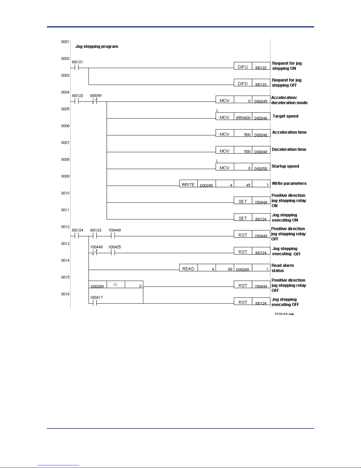
7-10
IM 34M6H55-02E 1st Edition : Apr 1, 2002-00
Figure 7.6 Jog Stepping Program
Page 66

7-11
IM 34M6H55-02E 1st Edition : Apr 1, 2002-00
Figure 7.7 Time Chart for the Jog Stepping Program
I00121
I00122
I00123
I00124
Y00449
X00425
Motor speed
F070107.VSD
Page 67

7-12
IM 34M6H55-02E 1st Edition : Apr 1, 2002-00
7.1.5 Origin Search
There are two ways to perform origin search operation: normal and automatic. In the
normal origin search operation, the origin search behavior is arbitrarily defined by an
application program. The automatic origin search operation uses entry parameters to
define the origin search behavior.
This section describes the normal origin search operation. For information on the
automatic origin search operation, see Section 7.1.6, “Automatic Origin Search.”
There are three external contact inputs related to the normal origin search. The origin
search mode specifies the action when each rising and falling edge of these three inputs
(six in total) is detected during the origin search using bit patterns (2 bits for each edge,
hence 12 bits in total).
In the example below, the search moves in the negative direction with the following
behavior: (1) Stops immediately when a rising edge of the negative-direction limit is
detected. (2) Decelerates and stops when a rising edge of the origin input is detected.
(3) Shifts to a Z-phase search when a falling edge of the origin search is detected. In
this case, the origin search mode is set as follows:
0 0 0 0 1 1 0 0 0 0 0 0 1 0 0 1
(“0C09” in hexadecimal)
For details on the origin search mode, see Section 3.5, “Origin Search.”
Figure 7.8 Example of Origin Search Operation
zzzz Conditions for Command Execution:
- The axis is not in an error state.
- The axis is in the End-of-Positioning status.
- No other command is being executed.
zzzz Note:
- If any of the conditions is not satisfied, the command is ignored and the Command
Execution ACK relay is not set. If the command is issued when the axis is in an
error state or not in the End-of-Positioning status, an alarm code is set in the alarm
status. The alarm code is automatically cleared when the Execute Command
output relay is reset. For details on alarm codes, see Section 8.3, “Alarm Codes.”
- The origin search ends when a specified external contact input is detected and the
axis is stopped. Change the parameters and begin the origin search again if you
want to continue the search in another direction or at a different speed.
- In the following cases, an error occurs and the origin search is aborted:
- The limit input of the origin search direction is set to be ignored but it is
detected.
- After shifting to Z-phase search, the limit switch of the origin search direction is
detected. This causes an error regardless of the setting.
- After shifting to Z-phase search, no Z-phase pulse is detected within the origin
search Z-phase search range.
- If you wish to change the setup values according to the status of an external contact
input at the beginning of the origin search, read the state in the Contact Input Status
before executing the origin search.
Negative-
direction
limit input
Origin input
(2)(3)(1)
Negative
direction
Positive
direction
F070108.VSD
Page 68

7-13
IM 34M6H55-02E 1st Edition : Apr 1, 2002-00
- After shifting to a Z-phase search, even if the external contact input that activates
the Stop Immediately or Decelerate and Stop operation is detected, the Z-search
operation will continue. (This behavior is different from the origin search in the
F3NC11-0N and F3NC12-0N modules)
- During the origin search, no error occurs even if the axis exceeds the range defined
by the positive and negative direction limit values.
zzzz Procedure:
1. Write the parameters and command code required for the normal origin search
operation to the positioning module with the WRITE or any other appropriate
instruction (set the command code to 2).
2. Set the Execute Command output relay. The Execute Command ACK input relay
will be set, and the automatic origin search starts. Operation continues until the
specified external contact input is detected. If there is an invalid parameter, the Error
Notification Input Relay will be set but not the Execute Command ACK Input Relay.
3. When Z-phase pulses are detected for the specified number of times after shifting to
a Z-phase search (if this number is specified as ‘’0," the module skips the Z-phase
search), the current position is specified as “Position 0” and the axis stops
immediately. After outputting the deviation pulse clear signal for a preset duration,
the End of Positioning input relay is set.
4. Confirm the status of the origin search by checking the origin search status. If the
origin search status is “0,” the origin search has ended following a successful Zphase search. For details on the origin search status, see Section 5.2, “Description
of Statuses”.
zzzz Sample Program:
This program starts the origin search using the Request to Search Origin input and stops
the search using a designated external contact input. If any error is detected during the
search, the search status is automatically reset. The program also uses some area for
non-required parameters because all the parameters are written at once. All required
parameters are preset in the data registers.
Major devices used
D00341 Command code
D00342 to D00345 Area for non-required parameters
D00346/D00347 Target speed
D00348 Acceleration time
D00349 Deceleration time
D00350/D00351 Startup speed
D00352 Origin search mode
D00353 Origin search direction
D00354 Z-phase edge selection
D00355 Z-phase search count
D00356/D00357 Z-phase search range
D00358 Deviation pulse clear time
D00389 Alarm code storage device
D00390 Origin search status
Y00433 Execute Command output relay
X00401 Execute Command ACK input relay
X00417 Error Notification input relay
X00425 End of Positioning input relay
I00099 Command execution prohibit condition (to be set elsewhere)
I00131 Request to search origin
I00132 Request to search origin (rising edge)
I00133 Origin search operating
I00134 Origin search executing
Page 69

7-14
IM 34M6H55-02E 1st Edition : Apr 1, 2002-00
Figure 7.9 Origin Search Program
Page 70

7-15
IM 34M6H55-02E 1st Edition : Apr 1, 2002-00
Figure 7.10 Time Chart for the Origin Search Program
I00131
I00132
I00133
I00134
Y00433
X00401
Motor speed
X00425
Stop
immediately
at origin
F070110.VSD
Page 71

7-16
IM 34M6H55-02E 1st Edition : Apr 1, 2002-00
7.1.6 Automatic Origin Search
There are two ways to perform origin search: normal and automatic. In normal origin
search, the search behavior is arbitrarily defined by an application program. The
automatic origin search operation uses entry parameters to define the origin search
behavior. This section describes the automatic origin search operation. For details on
the normal origin search operation, see Section 7.1.5, “Origin Search.”
Before initiating an automatic origin search, you must first set the automatic origin
search mode and other relevant entry parameters. For details on the automatic origin
search operation, see Section 3.6, “Automatic Origin Search.”
zzzz Conditions for Command Execution:
- The axis is not in an error state.
- The axis is in the End-of-Positioning status.
- No other command is being executed.
zzzz Note:
- If any of the conditions is not satisfied, the command is ignored and the Command
Execution ACK relay is not set. If the command is issued when the axis is in an
error state or not in the End-of-Positioning status, an alarm code is set in the alarm
status. The alarm code is automatically cleared when the Execute Command
output relay is reset. For details on alarm codes, see Section 8.3, “Alarm Codes.”
- In the following cases, an error occurs and the origin search is aborted:
- The limit switch for the direction opposite to the automatic origin search direction
is detected when the axis is moving in that direction at automatic origin search
speed 2.
- After shifting into Z-phase detection operation, no Z-phase pulse is detected
within the automatic origin search Z-phase search range.
- During automatic origin search, no error occurs even if the axis exceeds the range
defined by the positive and negative direction limit values.
zzzz Procedure:
1.Set the command code in the positioning module to 8 using a WRITE instruction or
any other appropriate instruction.
2. Set the Execute Command output relay. The Execute Command ACK input relay
will be set, and the automatic origin search starts. If there is an error in the
parameters, the Error Notification input relay is set but the Execute Command ACK
input relay is not set.
3. After shifting to Z-phase search, the axis stops when Z-phase pulses are detected
for the specified number of times (no shifting to a Z-phase search if the Z-phase
pulse count is set to 0), and that position becomes the origin (the value of the origin
is defined in the Automatic Origin Search Origin Offset parameter). The deviation
pulse clear signal is then output for a specified period, and then the End of
Positioning input relay is set.
4. Confirm the status of the origin search by checking the origin search status. If the
origin search status is “0,” the automatic origin search has ended following a
successful Z-phase search. For details on the origin search status, see Section 5.2,
“Description of Statuses”.
Page 72

7-17
IM 34M6H55-02E 1st Edition : Apr 1, 2002-00
zzzz Sample Program:
This program starts the automatic origin search operation using the Request to Start
Automatic Origin Search and stops the operation using Z-phase detected. The program
stops the operation if it detects an error during operation.
Major devices used
D00489 Alarm code storage device
D00490 Origin search status
Y00433 Execute Command output relay
X00401 Execute Command ACK input relay
X00417 Error Notification input relay
X00425 End of Positioning input relay
I00099 Command execution prohibit condition (set elsewhere)
I00136 Request to start automatic origin search
I00137 Request to start automatic origin search (rising edge)
I00138 Automatic origin search operating
I00139 Automatic origin search executing
Figure 7.11 Automatic Origin Search Program
Page 73

7-18
IM 34M6H55-02E 1st Edition : Apr 1, 2002-00
Figure 7.12 Time Chart for the Automatic Origin Search Program
I00136
I00137
I00138
I00139
Y00433
X00401
Motor speed
X00425
Stop
immediately
at origin
F070112.VSD
Page 74

7-19
IM 34M6H55-02E 1st Edition : Apr 1, 2002-00
7.1.7 Set Current Position
The Set Current Position command changes the current position of an axis in the End of
Positioning status.
zzzz Conditions for Command Execution:
- The axis is not in an error state.
- The axis is in the End-of-Positioning status.
- No other command is being executed.
zzzz Note:
- If any of the conditions is not satisfied, the command is ignored and the Command
Execution ACK relay is not set. If the command is issued when the axis is in an
error state or not in the End-of-Positioning status, an alarm code is written to the
alarm status. The alarm code is automatically cleared when the Execute Command
output relay is reset. For details on alarm codes, see Section 8.3, “Alarm Codes.”
- The new position must fall between the positive-direction limit and the negativedirection limit. An error occurs if a request is made to change the current position
beyond the limits of the range.
zzzz Procedure:
1. Set the Target Position parameter in the positioning module to the new target
position value and set the command code to 4 using a WRITE instruction or any
appropriate instruction.
2. Set the Execute Command output relay.
3. Reset the Execute Command output relay after confirming that the Execute
Command ACK input relay is set. If there is an entry parameter error, the Error
Notification input relay will be set but the Execute Command ACK input relay will not
be set.
4.Check that the Execute Command ACK input relay is reset.
zzzz Sample Program:
This is an example to set the current position. All required parameters are preset in the
data registers.
Major devices used
D00541 Command code
D00542 Area for non-required parameters
D00543/D00544 Target position (new current position)
D00589 Alarm code storage device
Y00433 Execute Command output relay
X00401 Execute Command ACK input relay
X00417 Error Notification input relay
X00425 End of Positioning input relay
I00099 Command execution prohibit condition (to be set elsewhere)
I00141 Request to write current position
I00142 Request to write current position (rising edge)
I00143 Waiting for Execute Command ACK
I00144 Command executing
Page 75

7-20
IM 34M6H55-02E 1st Edition : Apr 1, 2002-00
Figure 7.13 Set Current Position Program
Figure 7.14 Time Chart for the Set Current Position Program
I00141
I00142
I00143
I00144
Y00433
X00401
F070114.VSD
Page 76

7-21
IM 34M6H55-02E 1st Edition : Apr 1, 2002-00
7.1.8 Positioning Operation
This command executes a positioning operation towards a preset target position.
zzzz Conditions for Command Execution:
- The axis is not in an error state.
- The axis is in the End-of-Positioning status.
- No other command is being executed.
zzzz Note:
- If any of the conditions is not satisfied, the command is ignored and the Command
Execution ACK relay is not set. If the command is issued when the axis is in an
error state or not in the End-of-Positioning status, an alarm code is set in the alarm
status. The alarm code is automatically cleared when the Execute Command
output relay is reset. For details on alarm codes, see Section 8.3, “Alarm Codes.”
- If an invalid value is set for a parameter, a parameter error results and the axis does
not move.
zzzz Procedure:
1. Write the required parameters and command code to the positioning module using
the WRITE instruction or any other appropriate instruction (set the command code
to 0).
2. Set the Execute Command output relay.
3. The Execute Command ACK will be set and the axis starts positioning. Reset the
Execute Command output relay after confirming that the Execute Command ACK
input relay is set. If there is an entry parameter error, the Error Notification input
relay will be set, but the Execute Command ACK input relay will not be set.
4. The End of Positioning input relay is set when the output pulse count reaches the
target position. In general, when using servomotors, take note that there is some
time lag between the stopping of the pulse output and the stopping of the axis after
reaching the target position.
zzzz Sample Program
This is a sample program for a positioning operation. All required parameters are preset
in the data registers.
Major devices used
D00641 Command code
D00642 Target position mode
D00643/D00644 Target position
D00645 Acceleration/deceleration mode
D00646/D00647 Target speed
D00648 Acceleration time
D00649 Deceleration time
D00650/D00651 Startup speed
D00689 Alarm code storage device
Y00433 Execute Command output relay
X00401 Execute Command ACK input relay
X00417 Error Notification input relay
X00425 End of Positioning input relay
I00099 Command execution prohibit condition (to be set elsewhere)
I00151 Request to start positioning
I00152 Request to start positioning (rising edge)
I00153 Waiting for Execute Command ACK
I00154 Executing positioning operation
Page 77

7-22
IM 34M6H55-02E 1st Edition : Apr 1, 2002-00
Figure 7.15 Positioning Operation Program
Page 78

7-23
IM 34M6H55-02E 1st Edition : Apr 1, 2002-00
Figure 7.16 Time Chart for the Positioning Operation Program
I00151
I00152
I00153
I00154
Y00433
X00401
Motor speed
X00425
F070116.VSD
Page 79

7-24
IM 34M6H55-02E 1st Edition : Apr 1, 2002-00
7.1.9 Request to Decelerate and Stop
This Request to Decelerate and Stop command decelerates and stops a moving motor
during a positioning operation, origin search, etc. The rate of deceleration is determined
from the preset values at startup.
zzzz Conditions for Command Execution:
- The axis is not in an error state.
- The axis is not in jog stepping mode.
- No other command is being executed.
zzzz Note:
- If any of the conditions is not satisfied, the command is ignored and the Command
Execution ACK relay is not set. If the command is issued when the axis is in an
error state or in jog stepping mode, an alarm code is set in the alarm status. The
alarm code is automatically cleared when the Execute Command output relay is
reset. For details on alarm codes, see Section 8.3, “Alarm Codes.”
- You cannot execute the Decelerate and Stop command during jog stepping; you
must first terminate jog stepping.
- The Decelerate and Stop command is also accepted in the end-of-positioning
status. (The Execute Command ACK is set.)
zzzz Procedure:
1. Set the command code in the positioning module to 1 using a WRITE instruction or
any other appropriate instruction.
2. Set the Execute Command output relay.
3. Reset the Execute Command output relay after confirming that the Execute
Command ACK input relay is set. The axis starts decelerating when the Execute
Command ACK is set.
4.The End of Positioning input relay is set when the axis stops.
zzzz Sample Program:
This sample program performs a request to decelerate and stop. All required parameters
are preset in the data registers.
Major devices used
D00789 Alarm code storage device
Y00433 Execute Command output relay
X00401 Execute Command ACK input relay
X00425 End of Positioning input relay
I00099 Command execution prohibit condition (to be set elsewhere)
I00161 Request to decelerate and stop
I00162 Request to decelerate and stop (rising edge)
I00163 Waiting for Execute Command ACK
I00164 Waiting for decelerate and stop
Page 80

7-25
IM 34M6H55-02E 1st Edition : Apr 1, 2002-00
Figure 7.17 Request to Decelerate and Stop Program
Figure 7.18 Time Chart for the Request to Decelerate and Stop Program
I00161
I00162
I00163
I00164
Y00433
X00401
Motor Speed
X00425
F070118.VSD
Page 81

7-26
IM 34M6H55-02E 1st Edition : Apr 1, 2002-00
7.1.10 Request to Stop Immediately
The Request to Stop Immediately command stops a moving motor immediately without
any deceleration during a positioning operation, origin search, etc.
zzzz Conditions for the Command:
- The axis is not in an error state.
zzzz Note:
- If any of the conditions is not satisfied, the command is ignored and the Stop
Immediately ACK relay is not set. If the command is issued when the axis is in an
error state, an alarm code is set in the alarm status. The alarm code is
automatically cleared when the Stop Immediately output relay is reset. For details
on alarm codes, see Section 8.3, “Alarm Codes.”
- Take care when stopping a motor operating at high speed as the sudden stop may
result in a shock to the system.
- The Stop Immediately command is also accepted in the end-of-positioning status.
(The Execute Command ACK is set.)
zzzz Procedure:
1. Set the Stop Immediately output relay.
2. Reset the Stop Immediately output relay after confirming that the Stop Immediately
ACK input relay is set. The axis stops immediately when the Stop Immediately ACK
input relay is set.
3. The End of Positioning input relay is set when the axis stops.
zzzz Sample Program:
This sample program performs a request to stop immediately.
Major devices used
D00889 Alarm code storing device
Y00441 Stop Immediately output relay
X00409 Stop Immediately ACK input relay
X00425 End of Positioning input relay
I00171 Request to stop immediately
I00172 Request to stop immediately (rising edge)
I00173 Waiting for Stop Immediately ACK
I00174 Command executing
Page 82

7-27
IM 34M6H55-02E 1st Edition : Apr 1, 2002-00
Figure 7.19 Request to Stop Immediately Program
Figure 7.20 Time Chart for the Request to Stop Immediately Program
I00171
I00172
I00173
I00174
Y00433
X00401
Motor Speed
X00425
F070120.VSD
Page 83

7-28
IM 34M6H55-02E 1st Edition : Apr 1, 2002-00
7.1.11 Changing Speed during Operation
When the Change Speed command is issued during a positioning operation, the axis
immediately starts to accelerate (or decelerate) to the new speed at a rate determined
by the new speed and the acceleration (or deceleration) time. When the axis
subsequently decelerates and stops from the new target speed to complete the
positioning operation, or when the Decelerate-and-Stop command is issued, the
deceleration rate is determined by the new speed and the deceleration time.
zzzz Conditions for Command Execution:
- The axis is not in an error state.
- The axis is not in the End-of-Positioning status.
- The axis is not executing an origin search operation.
- The axis is not accelerating in a positioning operation.
- The axis is not decelerating in a positioning operation or in a jog stepping operation.
- The axis is not changing its target speed in a positioning operation.
- The axis can stop at the target position even after changing to the new speed.
- The axis is not changing its target position.
zzzz Note:
- If any of the conditions is not satisfied, the command is ignored and the Command
Execution ACK relay is not set.
If the command is issued but not all the conditions are satisfied, an alarm code is
set in the alarm status. The alarm code is automatically cleared when the Execute
Command output relay is reset. For details on alarm codes, see Section 8.3,
“Alarm Codes.”
- If the Change Speed command is issued during a jog stepping operation, the
module waits until all acceleration and deceleration has been completed before
executing the command. If a new Change Speed command is issued during the
wait, the previous command is discarded and only the new command is executed.
- If a command parameter is invalid, an error occurs and the axis stops immediately.
zzzz Procedure:
1. Write the required parameters and command code to the positioning module with
the WRITE instruction or any other appropriate instruction (set the command code
to 6).
2. Set the Execute Command output relay.
3. The Execute Command ACK input relay is set, and the Change Speed operation
starts. Reset the Execute Command output relay after confirming that the Execute
Command ACK input relay is set. If there is an invalid parameter, the Error
Notification input relay will be set, but the Execute Command ACK input relay will
not be set.
4. Confirm that the Execute Command ACK input relay is reset.
Page 84

7-29
IM 34M6H55-02E 1st Edition : Apr 1, 2002-00
zzzz Sample Program
This program changes speed during operation. All required parameters are preset in the
data registers.
Major devices used
D00941 Command code
D00942 to D00945 Area for non-required parameters
D00946/D00947 Target speed
D00948 Acceleration time
D00949 Deceleration time
D00989 Alarm code storage device
Y00433 Execute Command output relay
X00401 Execute Command ACK input relay
X00417 Error Notification input relay
I00099 Command execution prohibit condition (to be set elsewhere)
I00181 Request to change speed
I00182 Request to change speed (rising edge)
I00183 Waiting for Execute Command ACK
I00184 Command executing
Figure 7.21 Request to Change Speed Program
Page 85

7-30
IM 34M6H55-02E 1st Edition : Apr 1, 2002-00
Figure 7.22 Time Program for the Request to Change Target Speed Program
I00181
I00182
I00183
I00184
Y00433
X00401
F070122.VSD
Page 86

7-31
IM 34M6H55-02E 1st Edition : Apr 1, 2002-00
7.1.12 Changing Target Position during Positioning
When the Change Target Position command is issued during a positioning operation, the
module updates the target position and performs positioning to reach the new target
position. Changing the target speed, acceleration or deceleration is not allowed during
the execution of the change target position command.
zzzz Conditions for Command Execution:
- The axis is not in an error state.
- The axis is not in a jog stepping operation.
- The axis is not in an origin search operation.
- The axis is not in a change target position operation.
zzzz Note:
- If any of the conditions is not satisfied, the command is ignored and the Command
Execution ACK relay is not set. If the command is issued but not all the conditions
are satisfied, an alarm code is written to the alarm status. The alarm code is
automatically cleared when the Execute Command output relay is reset. For details
on alarm codes, see Section 8.3, “Alarm Codes.”
- If the Change Target Position command is issued in the End-of-Positioning status,
the command is executed the same way as a Start Positioning command.
- If the Change Target Position command is issued during acceleration, deceleration
or speed change, the execution of the command is suspended until the axis speed
becomes constant or the axis stops.
- When the Change Target Position command is being executed, no command other
than the Decelerate-and-Stop command and Stop Immediately command are
available.
- If a command parameter is invalid, an error occurs and the axis stops immediately.
zzzz Procedure:
1. Write the command parameters to the positioning module with the WRITE
instruction or any other appropriate instruction (set the command code to 7).
2.Set the Execute Command output relay.
3.The Execute Command ACK input relay is set, and the Change Target Position
operation begins. Reset the Execute Command output relay after confirming that
the Execute Command ACK input relay is set. If there is an invalid parameter, the
Error Notification input relay will be set, but the Execute Command ACK input relay
will not be set.
4.Confirm that the Execute Command ACK input relay is reset.
Page 87

7-32
IM 34M6H55-02E 1st Edition : Apr 1, 2002-00
zzzz Sample Program:
This program changes the target position during a positioning operation. All required
parameters are preset in the data registers.
Major devices used
D01041 Command code
D01042 Target position mode
D01043/D01044 Target position
D01089 Alarm code storage device
Y00433 Execute Command output relay
X00401 Execute Command ACK input relay
X00417 Error Notification input relay
I00099 Command execution prohibit condition (to be set elsewhere)
I00191 Request to change target position
I00192 Request to change target position (rising edge)
I00193 Waiting for Execute Command ACK
I00194 Command executing
Figure 7.23 Request to Change Target Position Program
Page 88

7-33
IM 34M6H55-02E 1st Edition : Apr 1, 2002-00
Figure 7.24 Time Chart for the Request to Change Target Position Program
I00191
I00192
I00193
I00194
Y00433
X00401
F070124.VSD
Page 89

7-34
IM 34M6H55-02E 1st Edition : Apr 1, 2002-00
7.1.13 Saving Entry Parameters
When all axes are at rest, you can save all entry parameters to the flash memory. You
can issue the Save Parameter command for any axis but the entry parameters of all
axes are saved to the flash memory, regardless.
zzzz Conditions for Command Execution:
- No axis is in an error state.
- All axes are in the End-of-Positioning state.
- No other command is being executed for any axis.
zzzz Note:
- If any of the conditions is not satisfied, the command is ignored and the Command
Execution ACK relay is not set. If the command is issued but not all the conditions
are satisfied, an alarm code is set in the alarm status. The alarm code is
automatically cleared when the Execute Command output relay is reset. For details
on alarm codes, see Section 8.3, “Alarm Codes.”
- As there is limit to the number of times data can be written to the flash memory
(100,000 times max.), you should save the entry parameters to the flash memory
only when required.
zzzz Procedure:
1.Set the command code to 9 (Save Parameter command) by writing to the
positioning module using a WRITE instruction or any other appropriate instruction.
2.Set the Execute Command output relay.
3.The Execute Command ACK input relay is set, and the entry parameters are saved
to the flash memory. Reset the Execute Command output relay after confirming that
the Execute Command ACK input relay is set.
4.Confirm that the Execute Command ACK input relay is reset.
zzzz Sample Program:
This program saves the entry parameters to the flash memory. All required parameters
are preset in the data registers.
Major devices used
D01189 Alarm code storage device
Y00433 Execute Command output relay
X00401 Execute Command ACK input relay
I00099 Command execution prohibit condition (to be set elsewhere)
I00201 Request to save entry parameters
I00202 Request to save entry parameters (rising edge)
I00203 Waiting for Execute Command ACK
I00204 Command executing
Page 90

7-35
IM 34M6H55-02E 1st Edition : Apr 1, 2002-00
Figure 7.25 Request to Save Entry Parameters Program
Figure 7.26 Time Chart for the Request to Save Entry Parameters Program
I00201
I00202
I00203
I00204
Y00433
X00401
F070126.VSD
Page 91

7-36
IM 34M6H55-02E 1st Edition : Apr 1, 2002-00
7.2 Accessing from a BASIC CPU
You can use the following the commands to access the module from a BASIC CPU. For
details of each command, see “Basic CPU Modules and YM-BASIC/FA Programming
Language” (IM 34M6Q22-01E).
Function Statement Format Explanation
Module use
declaration
ASSIGN YP18 = SL
SL: Slot number
Declares use of a module or CPU module.
Reading
parameters and
status
ENTER SL, n NOFORMAT; I
SL: Slot number
n : Data position number
I : Name of the integer/integer array
variable for storing the read data
Reads the parameter or status of the
data position number (n) of the module
installed in the slot (SL), and stores it in
the variable (I).
Writing
parameters
OUTPUT SL, n NOFORMAT; I
SL: Slot number
n
: Data position number
I
: Name of the Integer/integer array
variable for storing the write data
Overwrites a parameter at the data
position number (n) of the module
installed in the slot (SL) with the value
stored in the variable (I).
Reading input
relays
*1
STATUS SL, n; P
SL
: Slot number
n
: Data position number (101or 102)
P
: Name of the Integer variable for
storing the read data
Reads the status of the input relays of
the module that is installed in the slot
(SL), and stores it in the variable (P).
Writing output
relays
*2
CONTROL SL, n; P, M
SL
: Slot number
n
: Data position number (101 or 102)
P
: Output data
M
: Mask pattern
Overwrites the output relays of the
module installed in the slot (SL) with the
value stored in the variable (P). The
mask pattern (M) allows overwriting to
only specified output relays.
*1: For input relays, data position number 101 is for axes 1 to 4 (XVVV01 to XVVV16), and 102 is for axes 5 to 8
(XVVV17 to XVVV32).
*2: For output relays, data position number 101 is for axes 1 to 4 (YVVV33 to YVVV48), and 102 is for axes 5 to 8
(YVVV49 to YVVV64).
zzzz How To Handle 2-Word Data
You must convert long-word data to 2-word integer data before writing parameters to the
positioning module. When reading 2-word data from the positioning module, you must
convert the data to long-word data after reading the data as two integer variables.
LDAT : Long-word integer variable before conversion
IDD, IDU: Integer variable for storing the data after conversion
(low-order/high-order)
100 IDD=VAL(“$”+RIGHT$(LHEX$(LDAT),4))
110 IDU=VAL(“$”+LEFT$(LHEX$(LDAT),4))
ISD, ISU: Integer variable containing the 2 words read
(low-order/high-order)
LST : Long-word integer variable after conversion
100 LST=VAL(“$”+HEX$(ISU)+HEX$(ISD))
Page 92

7-37
IM 34M6H55-02E 1st Edition : Apr 1, 2002-00
7.2.1 Reading Module Statuses
This section explains how to read the status of the positioning module.
zzzz Note:
- The status of the positioning module can be read at any time. Use the ENTER
instruction to read the status.
- 2-word data status, such as the current position or current speed status, must be
read as two separate integer variables. Take care when reading long-word data.
See Chapter 5, “Status”.
zzzz Sample Program:
This sample program uses the ENTER instruction to read all the statuses.
It then converts 2-word data into long-word data and converts the speed data to
[pulses/s].
100 ENTER SL,81 NOFORMAT;I081
110 ENTER SL,82 NOFORMAT;I082
120 ENTER SL,83 NOFORMAT;I083
130 ENTER SL,84 NOFORMAT;I084
140 ENTER SL,85 NOFORMAT;I085
150 ENTER SL,86 NOFORMAT;I086
160 ENTER SL,87 NOFORMAT;I087
170 ENTER SL,88 NOFORMAT;I088
180 ENTER SL,89 NOFORMAT;I089
190 ENTER SL,90 NOFORMAT;I090
200 ENTER SL,91 NOFORMAT;I091
210 ENTER SL,92 NOFORMAT;I092
220 ENTER SL,93 NOFORMAT;I093
230 L081=VAL("$"+HEX$(I082)+HEX$(I081))
240 L083=VAL("$"+HEX$(I084)+HEX$(I083))
250 L085=VAL("$"+HEX$(I086)+HEX$(I085))
260 L092=VAL("$"+HEX$(I093)+HEX$(I092))
270 D085PPS=L085/65.536
Page 93

7-38
IM 34M6H55-02E 1st Edition : Apr 1, 2002-00
7.2.2 Set Parameter
The Set Parameter command sets the entry parameters.
zzzz Conditions for Command Execution:
- The axis is in the End-of-Positioning status.
- No other command is being executed.
zzzz Note:
- If any of the conditions is not satisfied, the command is ignored and the Command
Execution ACK relay is not set. If the command is issued when the axis is not in the
End-of-Positioning status, an alarm code is set in the alarm status. The alarm code
is automatically cleared when the Execute Command output relay is reset. For
details on alarm codes, see Section 8.3, “Alarm Codes.”
- An error arising from a Set Parameter command (error code 2VVV) cannot be
reset with the Reset Error command. Run the Set Parameter command again with
proper data.
zzzz Procedure:
1. Write the parameter values and command code to the positioning module with the
OUTPUT instruction.
2. Set the Execute Command output relay.
3. Reset the Execute Command output relay after confirming that the Execute
Command ACK input relay is set. Note that if there is an entry parameter error, the
Execute Command ACK input relay will not be set, but the Error Notification input
relay will be set. In this case, reset the Execute Command output relay, and return
to step 1.
4. Check that the Execute Command ACK input relay is reset.
zzzz Sample Program:
In this example, parameters are preset in integer variables (I01 to I25, and I41).
100 OUTPUT SL,1 NOFORMAT;I01
110 OUTPUT SL,2 NOFORMAT;I02
:
340 OUTPUT SL,25 NOFORMAT;I25
350 OUTPUT SL,41 NOFORMAT;I41
400 CONTROL SL,101;$0001,$0001
410 LOOP1@
420 STATUS SL,101;P
430 IF BIT(P,0)=0 THEN LOOP1@
440 CONTROL SL,101;$0000,$0001
450 LOOP2@
460 STATUS SL,101;P
470 IF BIT(P,0)=1 THEN LOOP2@
Page 94

7-39
IM 34M6H55-02E 1st Edition : Apr 1, 2002-00
7.2.3 Reset Error
The Reset Error command resets the error status of the positioning module.
zzzz Conditions for Command Execution:
- The axis is in error (other than an entry parameter error)
- No other command is being executed.
zzzz Note:
- The positioning module ignores all commands other than the Reset Error command
and Set Parameter command in an error status (i.e. when the Error Notification
input relay is set). Therefore, always execute the Reset Error command in an error
status. If the Reset Error command is issued when the axis is not in an error status,
or any command other than the Reset Error command or Set Parameter command
is issued when the axis is in an error status, an alarm code is set in the alarm
status. The alarm code is automatically cleared when the Execute Command output
relay is reset. For details on alarm codes, see Section 8.3, “Alarm Codes.” An entry
parameter error (error code 2VVV) arising from a Set Parameter command cannot
be reset using the Reset Error command. See Section 7.1.2, “Set Parameter.”
zzzz Procedure:
1. Write the command code to the positioning module with the OUTPUT instruction.
2. Set the Execute Command output relay.
3. Check that the Error Notification input relay is reset and reset the Execute
Command output relay.
4. Check that the Execute Command ACK input relay is reset.
zzzz Sample Program:
In this example, all output relays of the positioning module are reset during the Reset
Error operation. The error code retains its value even after the Reset Error operation.
Parameters are preset in an integer variable (I41).
100 STATUS SL,102;P
110 IF BIT(P,0)=0 THEN EXIT1@
120 ENTER SL,88 NOFORMAT;IERCODE
130 OUTPUT SL,41 NOFORMAT;I41
140 CONTROL SL,101;$0001,$0101
150 CONTROL SL,102;$0000,$0101
160 LOOP1@
170 STATUS SL,102;P
180 IF BIT(P,0)=1 THEN LOOP1@
190 CONTROL SL,101;$0000,$0001
200 EXIT1@
Page 95

7-40
IM 34M6H55-02E 1st Edition : Apr 1, 2002-00
7.2.4 Jog Stepping
When the Positive- (Negative-) direction Jog Stepping output relay is on, the motor
moves in the positive (negative) direction.
zzzz Conditions for Command Execution:
- The axis is not in an error state.
- The axis is in the End-of-Positioning status.
- No other command is being executed.
zzzz Note:
- If any of the conditions is not satisfied, the command is ignored. If the command is
issued when the axis is in an error state or not in the End-of-Positioning status, an
alarm code is set in the alarm status. The alarm code is automatically cleared when
the Execute Command output relay is reset. For details on alarm codes, see
Section 8.3, “Alarm Codes.”
- During jog stepping, the Stop Immediately command is valid but the Decelerateand-Stop command is ignored (the Execute Command ACK input relay is not set).
If the Decelerate-and-Stop command is issued during jog stepping, an alarm code is
set in the alarm status. Terminate jog stepping before executing the Decelerate-andStop command.
- During jog stepping, no error occurs even if the axis exceeds the range defined by
the positive direct limit value and the negative direction limit value.
zzzz Procedure:
1. Write the required parameters of the Jog Stepping command to the positioning
module with the OUTPUT instruction.
2. When the Positive-direction (Negative-direction) Jog Stepping output relay is set,
the axis moves according to the parameters and the End-of-Positioning input relay
is reset.
3. When the Positive-direction (Negative-direction) Jog Stepping output relay is reset,
the axis will decelerate and stop according to the parameters. After that, the End-ofpositioning input relay is set.
zzzz Sample Program:
This sample program shows the operation of Start Jog Stepping (JOGST@) and End
Jog Stepping (JOGEND@) in the positive direction. Required parameters are preset in
integer variables (I45 to I51).
100 JOGST@
110 OUTPUT SL,45 NOFORMAT;I45
120 OUTPUT SL,46 NOFORMAT;I46
:
170 OUTPUT SL,51 NOFORMAT;I51
180 CONTROL SL,102;$0001,$0001
300 JOGEND@
310 CONTROL SL,102;$0000,$0001
320 LOOP1@
330 STATUS SL,102;P
340 IF BIT(P,8)=0 THEN LOOP1@
Page 96

7-41
IM 34M6H55-02E 1st Edition : Apr 1, 2002-00
7.2.5 Origin Search
There are two ways to perform origin search: normal and automatic. In normal origin
search, the origin search behavior is arbitrarily defined by an application program; the
automatic origin search operation uses entry parameters to define the origin search
behavior.
This section describes the normal origin search operation. For details on the automatic
origin search operation, see Section 7.1.6, “Using Automatic Origin Search.”
There are three external contact inputs related to the normal origin search. The origin
search mode uses bit patterns (2 bits for each edge, 12 bits in total) to specify the
desired behavior when each rising and falling edge of these three inputs (six in total) is
detected during the origin search.
In the example below, the origin search proceeds in the negative direction with the
following behavior: (1) Stops immediately when a rising edge of the negative-direction
limit is detected. (2) Decelerates and stops when a rising edge of the origin input is
detected. (3) Shifts to a Z-phase search when a falling edge of the origin search is
detected. In this case, the origin search mode is set as follows:
0 0 0 0 1 1 0 0 0 0 0 0 1 0 0 1
(“0C09” in hexadecimal)
For the origin search mode, see Section 3.5, “Origin Search.”
Figure 7.27 Example of Origin Search Operation
Negative-
direction
limit input
Origin input
(2)(3)(1)
Negative
direction
Positive
direction
F070127.VSD
Page 97

7-42
IM 34M6H55-02E 1st Edition : Apr 1, 2002-00
zzzz Conditions for Command Execution:
- The axis is not in an error state.
- The axis is in the End-of-Positioning status.
- No other command is being executed.
zzzz Note:
- If any of the conditions is not satisfied, the command is ignored and the Command
Execution ACK relay is not set. If the command is issued when the axis is in an
error state or not in the End-of-Positioning status, an alarm code is set in the alarm
status. The alarm code is automatically cleared when the Execute Command
output relay is reset. For details on alarm codes, see Section 8.3, “Alarm Codes.”
- The origin search ends when a specified external contact input is detected and the
axis is stopped. Change the parameters and begin the origin search again if you
wish to continue the search in another direction or at a different speed.
- In the following cases, an error occurs and the origin search is aborted:
- The limit input of the origin-search direction is set to be ignored but is detected.
- After shifting to Z-phase search, the limit switch of the origin search direction is
detected (this always causes an error regardless of the setting).
- After shifting to Z-phase search, no Z-phase pulse is detected within the origin
search Z-phase search range.
- If you wish to change the setup values according to the state of the external contact
input at the beginning of the origin search, read the state with the Contact Input
Status before executing the origin search.
- After shifting to Z-phase search, even if the external contact input that sets the Stop
Immediately or Decelerate and Stop operation is detected, the Z-search operation
will continue. (This is different from an origin search in the F3NC11-0N and
F3NC12-0N modules)
- During the origin search, even if the axis exceeds the range defined by the positive
and negative direction limit values, no error occurs.
zzzz Procedure:
1. Write the entry and command parameters required for the origin search operation to
the positioning module with the OUTPUT instruction (set the command code to 2).
2. Set the Execute Command output relay. The Execute Command ACK input relay
will be set and the automatic origin search begins. Operation continues until the
specified external contact input is detected. If there is an invalid parameter, the Error
Notification Input Relay will be set but not the Execute Command ACK Input Relay.
3. When Z-phase pulses are detected for the specified number of times after shifting
to Z-phase search (if this number is specified as ‘’0," the module skips the
Z-phase search), the current position is specified as “Position 0” and the axis stops
immediately. After outputting the deviation pulse clear signal for a preset duration,
the End of Positioning input relay is set.
4. Confirm the state of origin search by checking the origin search status. If the origin
search status is “0,” the origin search has ended following a successful
Z-phase search. For details on the origin search status, see Section 5.2,
“Description of Statuses”.
Page 98

7-43
IM 34M6H55-02E 1st Edition : Apr 1, 2002-00
zzzz Sample Program:
This program starts the origin search using the Request to Search Origin input and stops
the search using a designated external contact input. If any error is detected during the
search, the search mode is automatically reset. All required parameters are preset in
integer variables (I41, and I46 to I58).
100 OUTPUT SL,46 NOFORMAT;I46
110 OUTPUT SL,47 NOFORMAT;I47
:
220 OUTPUT SL,58 NOFORMAT;I58
230 OUTPUT SL,41 NOFORMAT;I41
240 CONTROL SL,101;$0001,$0001
250 LOOP1@
260 STATUS SL,101;P
270 IF BIT(P,0)=0 THEN LOOP1@
280 CONTROL SL,101;$0000,$0001
290 LOOP2@
300 STATUS SL,102;P
310 IF BIT(P,8)=0 THEN LOOP2@
320 ENTER SL,90 NOFORMAT;IORGST
:
Page 99

7-44
IM 34M6H55-02E 1st Edition : Apr 1, 2002-00
7.2.6 Automatic Origin Search
There are two ways to perform origin search: normal and automatic. In normal origin
search, the origin search behavior is arbitrarily defined by an application program; the
automatic origin search operation uses entry parameters to define the origin search
behavior.
This section describes the automatic origin search operation. For the normal origin
search operation, refer to Section 7.2.5, “Origin Search.”
Before initiating the automatic origin search, you must first set the automatic origin
search mode and other relevant entry parameters. For details on automatic origin
search behavior, see Section 3.6, “Automatic Origin Search.”
zzzz Conditions for Command Execution:
- The axis is not in an error state.
- The axis is in the End-of-Positioning status.
- No other command is being executed.
zzzz Note:
- If any of the conditions is not satisfied, the command is ignored and the Command
Execution ACK relay is not set. If the command is issued when the axis is in an
error state or not in the End-of-Positioning status, an alarm code is set in the alarm
status. The alarm code is automatically cleared when the Execute Command
output relay is reset. For details on alarm codes, see Section 8.3, “Alarm Codes.”
- In the following cases, an error occurs and the origin search is aborted:
- The limit switch for the direction opposite the automatic origin search direction is
detected when the axis is moving in that direction at automatic origin search
speed 2.
- After shifting into Z-phase detection, no Z-phase pulse is detected within the
automatic origin search Z-phase search range.
- During the automatic origin search, no error occurs even if the axis exceeds the
range defined by the positive and negative direction limit values.
zzzz Procedure:
1. Set the command code to 8 by writing to the positioning module using an OUTPUT
instruction.
2. Set the Execute Command output relay. The Execute Command ACK input relay
will be set, and the automatic origin search begins. The operation continues until
the automatic origin search completes and the axis stops moving. If there is an
invalid parameter, the Error Notification input relay will be set but the Execute
Command ACK input relay will not be set.
3. After shifting to Z-phase search, the axis stops when Z-phase pulses are detected
for the specified number of times (if the Z-phase pulse count is set to 0, the module
skips the Z-phase search) and that position becomes the origin (the value of the
origin is defined in the Automatic Origin Search Origin Offset parameter). The
deviation pulse clear signal is then output for a specified period and the End of
Positioning input relay is set.
4. Confirm the state of the origin search by checking the origin search status. If the
origin search status is “0,” the automatic origin search has ended following a
successful Z-phase search. For details on the origin search status, see Section 5.2,
“Description of Statuses.”
Page 100

7-45
IM 34M6H55-02E 1st Edition : Apr 1, 2002-00
zzzz Sample Program:
This program starts the automatic origin search operation using the Request to Start
Automatic Origin Search, performs Z-phase detection and stops the operation. The
program also stops the operation if it detects an error during the operation. All required
parameters are preset in an integer variable (I41).
100 OUTPUT SL,41 NOFORMAT;I41
110 CONTROL SL,101;$0001,$0001
120 LOOP1@
130 STATUS SL,101;P
140 IF BIT(P,0)=0 THEN LOOP1@
150 CONTROL SL,101;$0000,$0001
160 LOOP2@
170 STATUS SL,102;P
180 IF BIT(P,8)=0 THEN LOOP2@
190 ENTER SL,90 NOFORMAT;IORGST
:
 Loading...