

Page 1

User’s
Manual
Positioning Modules
(with Multi-channel Pulse Output)
Model: F3YP04-0N, F3YP08-0N
IM 34M6H55-01E
Yokogawa Electric Corporation
IM 34M6H55-01E
3rd Edition
Page 2

Applicable Product
● Range-free Multi-controller FA-M3
Model : F3YP04-0N, F3YP08-0N
Name: Positioning Module (with Multi-Channel Pulse Output)
The document number and document model code for this manual are given below:
Refer to the document number in all communications; also refer to the document number or
the document model code when purchasing additional copies of this manual.
Document No. : IM 34M6H55-01E
Document Model Code : DOCIM
i
Media No. IM 346H55-01E (CD) 3rd Edition : Apr, 2002 (YK)
All Right Reserved Copyright © 1999, Yokogawa Electric Corporation
IM 34M6H55-01E 3rd Edition : Apr 1, 2002-00
Page 3
Important
About This Manual
- This Manual should be passed on to the end user.
- Before using the controller, read this manual thoroughly to have a clear understanding
of the controller.
- This manual explains the functions of this product, but there is no guarantee that they
will suit the particular purpose of the user.
- Under absolutely no circumstances may the contents of this manual be transcribed or
copied, in part or in whole, without permission.
- The contents of this manual are subject to change without prior notice.
- Every effort has been made to ensure accuracy in the preparation of this manual.
However, should any errors or omissions come to the attention of the user, please
contact the nearest Yokogawa Electric representative or sales office.
Safety Precautions when Using/Maintaining the Product
ii
- The following safety symbols are used on the product as well as in this manual.
CAUTION
Danger. This symbol on the product indicates that the operator must follow the
instructions laid out in this instruction manual to avoid the risk of personnel injuries,
fatalities, or damage to the instrument. Where indicated by this symbol, the manual
describes what special care the operator must exercise to prevent electrical shock or
other dangers that may result in injury or the loss of life.
Protective Ground Terminal. Before using the instrument, be sure to ground this
terminal.
Function Ground Terminal. Before using the instrument, be sure to ground this
terminal.
Alternating current. Indicates alternating current.
Direct current. Indicates direct current.
The following symbols are used only in the instruction manual.
IM 34M6H55-01E 3rd Edition : Apr 1, 2002-00
Page 4

WARNING
Indicates a “Warning”.
Draws attention to information essential to prevent hardware damage, software damage
or system failure.
CAUTION
Indicates a “Caution”
Draws attention to information essential to the understanding of operation and functions.
TIP
Indicates a “TIP”
Gives information that complements the present topic.
SEE ALSO
Indicates a SEE ALSO reference.
Identifies a source to which to refer.
iii
- For the protection and safe use of the product and the system controlled by it, be sure
to follow the instructions and precautions on safety stated in this manual whenever
handling the product. Take special note that if you handle the product in a manner
other than prescribed in these instructions, the protection feature of the product may
be damaged or impaired. In such cases, Yokogawa cannot guarantee the quality,
performance, function or safety of the product.
- When installing protection and/or safety circuits such as thunderbolt protection devices and equipment for the product and control system as well as designing or
installing separate protection and/or safety circuits for fool-proof design and fail-safe
design of processes and lines using the product and the system controlled by it, the
user should implement it using devices and equipment, additional to this product.
- If component parts or consumable are to be replaced, be sure to use parts specified
by the company.
- This product is not designed or manufactured to be used in critical applications which
directly affect or threaten human lives and safety — such as nuclear power equipment,
devices using radioactivity, railway facilities, aviation equipment, air navigation facilities, aviation facilities or medical equipment. If so used, it is the user’s responsibility to
include in the system additional equipment and devices that ensure personnel safety.
- Do not attempt to modify the product.
Exemption from Responsibility
- Yokogawa Electric Corporation (hereinafter simply referred to as Yokogawa Electric)
makes no warranties regarding the product except those stated in the WARRANTY
that is provided separately.
- Yokogawa Electric assumes no liability to any party for any loss or damage, direct or
indirect, caused by the use or any unpredictable defect of the product.
IM 34M6H55-01E 3rd Edition : Apr 1, 2002-00
Page 5

Software Supplied by the Company
- Yokogawa Electric makes no other warranties expressed or implied except as provided in its warranty clause for software supplied by the company.
- Use the software with one computer only. You must purchase another copy of the
software for use with each additional computer.
- Copying the software for any purposes other than backup is strictly prohibited.
- Store the original media, such as floppy disks, that contain the software in a safe
place.
- Reverse engineering, such as decompiling of the software, is strictly prohibited.
- No portion of the software supplied by Yokogawa Electric may be transferred, exchanged, or sublet or leased for use by any third party without prior permission by
Yokogawa Electric.
iv
IM 34M6H55-01E 3rd Edition : Apr 1, 2002-00
Page 6

General Requirements for Using the FA-M3
● Avoid installing the FA-M3 in the following locations:
- Where the instrument will be exposed to direct sunlight, or where the operating temperature exceeds the range 0°C to 55°C (0°F to 131°F).
- Where the relative humidity is outside the range 10 to 90%, or where sudden temperature changes may occur and cause condensation.
- Where corrosive or flammable gases are present.
- Where the instrument will be exposed to direct mechanical vibration or shock.
- Where the instrument may be exposed to extreme levels of radioactivity.
● Use the correct types of wire for external wiring:
- Use copper wire with temperature ratings greater than 75°C.
● Securely tighten screws:
- Securely tighten module mounting screws and terminal screws to avoid problems
such as faulty operation.
v
- Tighten terminal block screws with the correct tightening torque as given in this
manual.
● Securely lock connecting cables:
- Securely lock the connectors of cables, and check them thoroughly before turning on
the power.
● Interlock with emergency-stop circuitry using external relays:
- Equipment incorporating the FA-M3 must be furnished with emergency-stop circuitry
that uses external relays. This circuitry should be set up to interlock correctly with
controller status (stop/run).
● Ground for low impedance:
- For safety reasons, connect the [FG] grounding terminal to a Japanese Industrial
Standards (JIS) Class D Ground
Ground). For compliance to CE Marking, use cables such as twisted cables which can
ensure low impedance even at high frequencies for grounding.
*1 Japanese Industrial Standard (JIS) class D Ground means grounding resistance of 100Ω max.
*1
(Japanese Industrial Standards (JIS) Class 3
● Configure and route cables with noise control considerations:
- Perform installation and wiring that segregates system parts that may likely become
noise sources and system parts that are susceptible to noise. Segregation can be
achieved by measures such as segregating by distance, installing a filter or segregating the grounding system.
● Configure for CE Marking Conformance:
- For compliance to CE Marking, perform installation and cable routing according
to the description on compliance to CE Marking in the “Hardware Manual”
(IM34M6C11-01E).
IM 34M6H55-01E 3rd Edition : Apr 1, 2002-00
Page 7

● Keep spare parts on hand:
- Stock up on maintenance parts including spare modules, in advance.
● Discharge static electricity before operating the system:
- Because static charge can accumulate in dry conditions, first touch grounded metal to
discharge any static electricity before touching the system.
● Never use solvents such as paint thinner for cleaning:
- Gently clean the surfaces of the FA-M3 with a cloth that has been soaked in water or a
neutral detergent and wringed.
- Do not use volatile solvents such as benzine or paint thinner or chemicals for cleaning,
as they may cause deformity, discoloration, or malfunctioning.
● Avoid storing the FA-M3 in places with high temperature or humidity:
- Since the CPU module has a built-in battery, avoid storage in places with high
temperature or humidity.
- Since the service life of the battery is drastically reduced by exposure to high
temperatures, take special care (storage temperature should be from –20
- There is a built-in lithium battery in a CPU module and temperature control module
which serves as backup power supply for programs, device information and
configuration information. The service life of this battery is more than 10 years in
standby mode at room temperature. Take note that the service life of the battery may
be shortened when installed or stored at locations of extreme low or high
temperatures. Therefore, we recommend that modules with built-in batteries be stored
at room temperature.
°C to 75°C).
vi
● Always turn off the power before installing or removing modules:
- Failing to turn off the power supply when installing or removing modules, may result in
damage.
● Do not touch components in the module:
- In some modules you can remove the right-side cover and install ROM packs or
change switch settings. While doing this, do not touch any components on the printedcircuit board, otherwise components may be damaged and modules may fail to work.
IM 34M6H55-01E 3rd Edition : Apr 1, 2002-00
Page 8

Introduction
■ Overview of the Manual
This user’s manual, “Positioning Module with Multi-channel Pulse Output,” explains the
specifications and provides information necessary for operation of the positioning modules,
F3YP04-0N and F3YP08-0N, used with an FA-M3 controller.
Before using the modules, read this manual thoroughly to have a clear understanding for
proper operation. Keep this manual on hand for future reference.
■ Other Manuals
Refer to the following manuals.
● For sequence CPU functions:
- Sequence CPU Modules - Functions (for F3SP21, F3SP25 and F3SP35)
(IM 34M6P12-02E)
- Sequence CPU Modules - Functions (for F3SP28, F3SP38, F3SP53 and F3SP58)
(IM 34M6P13-01E)
vii
● For sequence CPU instructions:
- Sequence CPU Modules - Instructions (IM 34M6P12-03E)
● For creating programs using ladders:
- FA-M3 Programming Tool WideField (IM 34M6Q14-01E)
- FA-M3 Programming Tool WideField - Application (IM 34M6Q14-02E)
● For the FA-M3 specifications and configurations*1, installation and
wiring, maintenance, and module installation limits for the whole system:
- Hardware Manual (IM 34M6C11-01E)
*1: Refer to the relevant product manuals for specifications except for power supply modules, base modules, input/
output modules, cables and terminal units.
IM 34M6H55-01E 3rd Edition : Apr 1, 2002-00
Page 9

Copyrights and Trademarks
■ Copyrights
Copyrights of the programs and online manual included in this CD-ROM belong to
Yokogawa Electric Corporation.
This online manual may be printed but PDF security settings have been made to prevent
alteration of its contents.
This online manual may only be printed and used for the sole purpose of operating this
product. When using a printed copy of the online manual, pay attention to possible inconsistencies with the latest version of the online manual. Ensure that the edition agrees with
the latest CD-ROM version.
Copying, passing, selling or distribution (including transferring over computer networks) of
the contents of the online manual, in part or in whole, to any third party, is strictly prohibited.
Registering or recording onto video tapes and other media is also prohibited without expressed permission of Yokogawa Electric Corporation.
■ Trademarks
viii
The trade names and company names referred to in this manual are either trademarks or
registered trademarks of their respective companies.
IM 34M6H55-01E 3rd Edition : Apr 1, 2002-00
Page 10

FA-M3
Positioning Module
(with Multi-channel Pulse Output)
IM 34M6H55-01E 3rd Edition
CONTENTS
Applicable Product ............................................................................................... i
Important ...............................................................................................................ii
Introduction......................................................................................................... vii
Copyrights and Trademarks .............................................................................. viii
1. Overview ................................................................................................. 1-1
2. Specifications ......................................................................................... 2-1
2.1 General Specifications ................................................................................... 2-1
2.2 Operating Environment .................................................................................. 2-2
2.3 Model and Suffix Codes.................................................................................. 2-2
2.4 Components and Functions ........................................................................... 2-3
2.5 External Dimensions ...................................................................................... 2-4
2.6 Terminal Assignments and Connections ...................................................... 2-5
2.7 Applicable External Interface Connectors..................................................... 2-6
Toc-1
3. Function Overview.................................................................................. 3-1
3.1 Positioning Operation..................................................................................... 3-2
3.2 Jog Stepping ................................................................................................... 3-3
3.3 Contact Inputs ................................................................................................. 3-3
3.4 Z-phase Encoder Input ................................................................................... 3-3
3.5 Origin Search .................................................................................................. 3-4
3.6 Deviation Pulse Clear Signal Output.............................................................. 3-6
3.7 Linear-Interpolated Operation ........................................................................ 3-6
4. Parameters .............................................................................................. 4-1
4.1 Parameters ...................................................................................................... 4-1
4.1.1 Entry Parameters.............................................................................. 4-4
4.1.2 Command Parameters ...................................................................... 4-4
4.2 Parameters Required for Each Command ..................................................... 4-5
4.3 Descriptions of Parameters............................................................................ 4-6
4.3.1 Entry Parameters.............................................................................. 4-6
4.3.2 Command Parameters ...................................................................... 4-7
4.4 Examples of Setting Entry Parameters .......................................................... 4-9
IM 34M6H55-01E 3rd Edition : Apr 1, 2002-00
Page 11

Toc-2
5. Status ...................................................................................................... 5-1
5.1 List of Status ................................................................................................... 5-2
5.2 Description of Status ...................................................................................... 5-3
6. Input/Output Relays................................................................................ 6-1
6.1 Output Relays.................................................................................................. 6-1
6.2 Input Relays .................................................................................................... 6-2
7. Accessing Modules ................................................................................ 7-1
7.1 Accessing from the Sequence CPU ............................................................... 7-1
7.1.1 Reading the Module Status ............................................................... 7-2
7.1.2 Set Parameter .................................................................................. 7-3
7.1.3 Error Reset ....................................................................................... 7-5
7.1.4 Jog Stepping .................................................................................... 7-7
7.1.5 Using Origin Search .......................................................................... 7-9
7.1.6 Set Current Position ........................................................................ 7-12
7.1.7 Positioning Operation ...................................................................... 7-14
7.1.8 Request to Decelerate and Stop ..................................................... 7-16
7.1.9 Request to Stop Immediately .......................................................... 7-18
7.2 Accessing from BASIC CPU......................................................................... 7-20
7.2.1 Reading the Module Status ............................................................. 7-21
7.2.2 Set Parameter ................................................................................ 7-22
7.2.3 Error Reset ..................................................................................... 7-23
7.2.4 Jog Stepping .................................................................................. 7-24
7.2.5 Origin Search ................................................................................. 7-25
7.2.6 Set Current Position ........................................................................ 7-27
7.2.7 Positioning Operation ...................................................................... 7-28
7.2.8 Request to Decelerate and Stop ..................................................... 7-29
7.2.9 Request to Stop Immediately .......................................................... 7-30
8. Errors and Troubleshooting.................................................................... 8-1
8.1 Troubleshooting Flow ..................................................................................... 8-1
8.2 Error Codes ..................................................................................................... 8-2
9. External Contact Signals ........................................................................ 9-1
9.1 Pulse Output ................................................................................................... 9-1
9.2 External Contact Input .................................................................................... 9-2
9.3 Encoder Z-phase Input ................................................................................... 9-3
9.4 Deviation Pulse Clear Signal Output.............................................................. 9-4
10. Examples of Connections to Servo Drivers......................................... 10-1
10.1 Example of Connection to Oriental Motor Driver ........................................ 10-2
10.2 Example of Connection to YASKAWA Electric ∑II-Series Driver ................ 10-3
10.3 Example of Connection to Sanyo Denki PZ Series Driver ......................... 10-4
Revision Information ............................................................................................ i
IM 34M6H55-01E 3rd Edition : Apr 1, 2002-00
Page 12
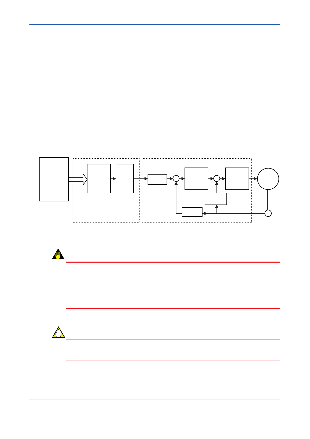
1. Overview
Models F3YP04-0N-and F3YP08-0N are advanced positioning modules (hereinafter
referred to as the modules or positioning modules) used to control servo drivers and
thereby the speed and position of pulse-driven motors. Driven by commands from the CPU
module of the FA-M3 controller, the positioning module generates paths for positioning and
outputs positioning command values in the form of pulse trains.
One module alone can control different types of motors/drivers. It can control up to 4 (the
F3YP04-0N module) or up to 8 (the F3YP08-0N module) pulse motors or servo motors.
When in use, the positioning modules are attached to the base module of an FA-M3 controller.
Features
- Compared with the original positioning module, which allows up to 2 controlled axes
per slot, this module allows up to 8 controlled axes from one slot.
- With a short startup time (6 ms maximum), it can come into action quickly and operate
in synchronization with peripheral equipment.
1-1
High-end
CPU module
Positioning module
Path
generation
Figure 1.1 Operating Principle of Positioning Module (with Multi-channel Pulse Output)
Pulse
Output
Counter
Servo driver
Position
controller
Counter
Speed
detector
Speed
controller
Motor
Encoder
F0101.EPS
WARNING
In order to ensure safety if the positioning module or servo driver fails or if any of the signal
lines is disconnected, be SURE to take necessary safety measures in your system design.
Such measures should include automatically shutting down the power to a motor if the
motor runs in excess of the specified normal operating limits. An external emergency stop
circuit should be built in to shut down the power to the motor and to stop it immediately if
the motor operates in an unexpected manner due to machine fault or misoperation.
CAUTION
When controlling a servo motor with the positioning module, choose a position-control
servo driver. Velocity-control and torque-control servo drivers do not meet this application.
IM 34M6H55-01E 3rd Edition : Apr 1, 2002-00
Page 13

Blank Page
Page 14

2. Specifications
2.1 General Specifications
2-1
Item
Number of controlled axes
Number of axes controlled
simultaneously
Pulse output method
Maximum velocity
Acceleration/deceleration method
Acceleration/deceleration time
Command pulse range
Command velocity
Origin position search method
Origin position search velocity
External contact input
External contact output
Data backup
Startup time
Current consumption
External power supply
External wiring
External dimensions
Weight
Note: Not including protrusions (see the external dimension diagram for more details).
F3YP04-0N Module F3YP08-0N Module
48
48
RS422A-conformed differential output
Clockwise/counterclockwise rotation pulse output for each axis
250,000 pps
Automatic-trapezoidal acceleration/deceleration
User-definable for start-up speed
0 to 32767 ms (separate for acceleration/deceleration)
–134,217,728 to 134,217,727
0.1 to 250,000 pps
User-definable using a combination of external contact inputs
User-definable using a command speed range
Positive direction limit input, negative direction limit input, origin
position input, Z-phase input
Deviation pulse clear signal
By CPU module
6 ms max.
300 mA 350 mA
5 V DC ±5%, 350 mA 5 V DC ±5%, 700 mA
48-pin connector (one unit) 48-pin connector (two units)
28.9 (W) × 100 (H) × 83.2 (D) (mm)
110 g 130 g
Specifications
(Note)
TC0201.EPS
IM 34M6H55-01E 3rd Edition : Apr 1, 2002-00
Page 15

2.2 Operating Environment
There are no restrictions on the CPU modules with which the positioning modules can be
used.
2.3 Model and Suffix Codes
Model Suffix Code Style Code Option Code Remarks
F3YP04 -0N . . . . . . 4-axis, multi-channel pulse output
F3YP08 -0N . . . . . . 8-axis, multi-channel pulse output
2-2
Maximum 250,000 pps
Maximum 250,000 pps
TC0203.EPS
IM 34M6H55-01E 3rd Edition : Apr 1, 2002-00
Page 16

2.4 Components and Functions
● F3YYP04-0N (4-axis module)
2-3
YP04-0N
RDY
ERR
POSIT
RDY indicator:
Lit when the internal circuitry is functioning normally.
ERR indicator:
Lit if an error occurs.
For details, refer to Section 8.2, “Error Codes.”
Connector for axes 1 to 4 (48P)
Connects to external I/O devices such as servo motors and limits switches.
● F3YP08-0N modules (8-axis module)
YP08-0N
RDY
ERR
POSIT
RDY indicator:
Lit when the internal circuitry is functioning normally.
ERR indicator:
Lit if an error occurs.
For details, refer to Section 8.2, “Error Codes.”
Connector for axes 1 to 4 (48P)
Connector for axes 5 to 8 (48P)
Connects to external I/O devices such as servo motors and limit switches.
FC0204.EPS
Even though the ERR LED lights up, normal axes other than the error axis can still be
operated.
IM 34M6H55-01E 3rd Edition : Apr 1, 2002-00
Page 17

2.5 External Dimensions
2-4
Unit: mm
83.2 28.9
External Dimension Diagram for F3YP04-0N Module
1.3
2
100
FC0205.EPS
IM 34M6H55-01E 3rd Edition : Apr 1, 2002-00
Page 18

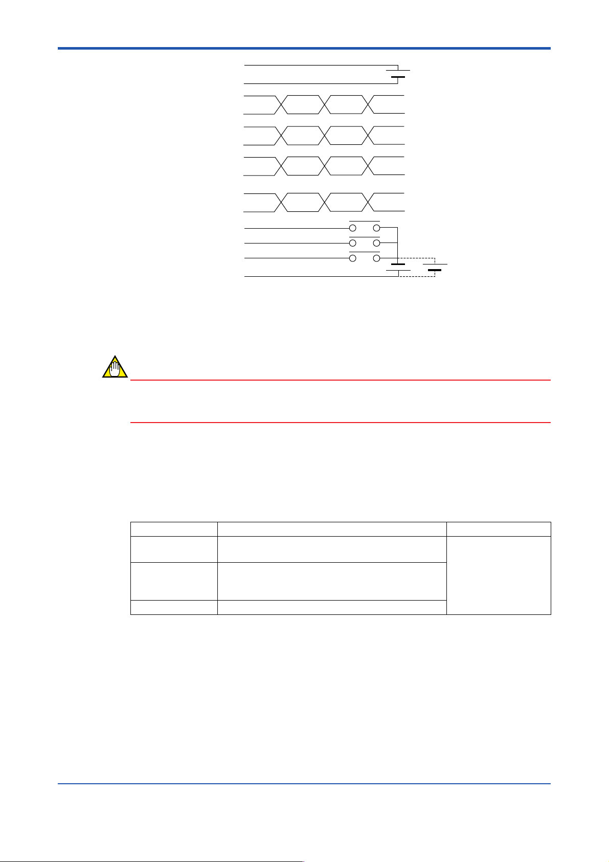
2.6 Terminal Assignments and Connections
2-5
RDY
ERR
YP04-0N
24b Axis 4 Z-phase – 24a Axis 2 Z-phase input –
23b Axis 4 Z-phase input + 23a Axis 2 Z-phase input +
22b Axis 4 clockwise pulse + 22a Axis 2 clockwise pulse +
21b Axis 4 clockwise pulse – 21a Axis 2 clockwise pulse –
20b Axis 4
19b Axis 4
18b Axis 4 deviation pulse clear 18a Axis 2 deviation pulse clear
17b Axis 4
16b Axis 3 Z-phase input – 16a Axis 1 Z-phase input –
15b Axis 3 Z-phase input + 15a Axis 1 Z-phase input +
14b Axis 3 clockwise pulse + 14a Axis 1 clockwise pulse +
13b Axis 3 clockwise pulse – 13a Axis 1 clockwise pulse –
12b Axis 3
11b Axis 3
10b Axis 3 deviation pulse clear 10a Axis 1 deviation pulse clear
9b Axis 3
8b External power 5Vin 8a External power 5Vin (GND)
7b Axis 4 origin input 7a Bi-axis origin input
6b Axis 4
5b Axis 4
4b Axis 3 origin input 4a Axis 1 origin input
3b Axis 3
2b Axis 3
1b Contact input common 1a Contact input common
counterclockwise pulse +
counterclockwise pulse –
deviation pulse clear (GND)
counterclockwise pulse +
counterclockwise pulse –
deviation pulse clear (GND)
positive-direction limit input
negative-direction limit input
positive-direction limit input
negative-direction limit input
20a Axis 2
19a Axis 2
17a Axis 2
12a Axis 1
11a Axis 1
9a Axis 1
6a Axis 2
5a Axis 2
3a Axis 1
2a Axis 1
POSIT
counterclockwise pulse +
counterclockwise pulse –
deviation pulse clear (GND)
counterclockwise pulse +
counterclockwise pulse –
deviation pulse clear (GND)
positive-direction limit input
negative-direction limit input
positive-direction limit input
negative-direction limit input
RDY
ERR
YP08-0N
POSIT
24b Axis 8 Z-phase input – 24a Axis 5 Z-phase input –
23b Axis 8 Z-phase input + 23a Axis 5 Z-phase input +
22b Axis 8 clockwise pulse + 22a Axis 5 clockwise pulse +
21b Axis 8 clockwise pulse – 21a Axis 5 clockwise pulse –
20b Axis 8
19b Axis 8
18b Axis 8 deviation pulse 18a Axis 6 deviation pulse clear
17b Axis 8
16b Axis 7 Z-phase input – 16a Axis 5 Z-phase input –
15b Axis 7 Z-phase input + 15a Axis 5 Z-phase input +
14b Axis 7 clockwise pulse + 14a Axis 5 clockwise pulse +
13b Axis 7 clockwise pulse – 13a Axis 5 clockwise pulse –
12b Axis 7
11b Axis 7
10b Axis 7 deviation pulse clear 10a Axis 5 deviation pulse clear
9b Axis 7
8b External power 5Vin 8a External power 5 Vin (GND)
7b Axis 8 origin input 7a Axis 6 origin input
6b Axis 8
5b Axis 8
4b Axis 7 origin input 4a Axis 5 origin input
3b Axis 7
2b Axis 7
1b Contact input common 1a Contact input common
counterclockwise pulse +
counterclockwise pulse –
deviation pulse clear (GND)
counterclockwise pulse +
counterclockwise pulse –
deviation pulse clear (GND)
positive-direction limit input
negative-direction limit input
positive-direction limit input
negative-direction limit input
20a Axis 5
19a Axis 5
17a Axis 6
12a Axis 5
11a Axis 5
9a Axis 5
6a Axis 6
5a Axis 6
3a Axis 5
2a Axis 5
counterclockwise pulse +
counterclockwise pulse –
deviation pulse clear (GND)
counterclockwise pulse +
counterclockwise pulse –
deviation pulse clear (GND)
positive-direction limit input
negative-direction limit input
positive-direction limit input
negative-direction limit input
FC0206_1.EPS
IM 34M6H55-01E 3rd Edition : Apr 1, 2002-00
Page 19
2-6
External power 5Vin
External power 5Vin (GND)
Clockwise pulse –
Clockwise pulse +
Counterclockwise pulse –
Counterclockwise pulse +
Deviation pulse clear
Deviation pulse clear (GND)
Z-phase input –
Z-phase input +
Origin input
Positive-direction limit input
Negative-direction limit input
Contact input common
+
5 V DC
–
24 V DC
FC0206_2.EPS
Contact input common and the external power supply 5Vin/GND are common to all axes
(they are connected through the internal circuitry even between different connector
terminals). Other signals are independent for each axis.
CAUTION
Be sure to connect the external power supply (5 V DC) with the correct polarity. The internal
circuitry may be damaged if it is connected incorrectly.
For details on the external connection signals, please refer to Chapter 9, “External Connection Signals.”
2.7 Applicable External Interface Connectors
Connection Applicable Connector Remarks
Soldered FCN-361J048-AU connector
FCN-360C048-B connector cover (Fujitsu Limited)
Crimp-on FCN-363J048 housing
FCN-363J-AU contacts
FCN-360C048-B connector cover (Fujitsu Limited)
Pressure-welded FCN-367J048-AU/F connector (Fujitsu Limited)
Purchase the desired
connector kit
separately.
TC0207.EPS
IM 34M6H55-01E 3rd Edition : Apr 1, 2002-00
Page 20

3. Function Overview
This chapter explains the major functions of the positioning modules. For details on how to
use each function, see Chapter 7. Table 3.1 summarizes the functions discussed in this
chapter.
Table 3. Major Functions
Function Description
Positioning operation Carries out normal positioning.
Jog stepping Allows a motor to be rotated manually, for example, during position
teaching.
Contact input Inputs external contact signals such as a limit-switch signal or an
ORIGIN input signal.
Z-phase encoder input Inputs a Z-phase encoder signal used to search for the origin.
Origin-search operation Searches for the origin using an external contact input.
Deviation pulse clear signal Outputs a deviation pulse clear signal when an origin position search
is completed.
Linear-interpolated operation Carries out a multi-axial linear-interpolated operation.
3-1
T0301.EPS
IM 34M6H55-01E 3rd Edition : Apr 1, 2002-00
Page 21
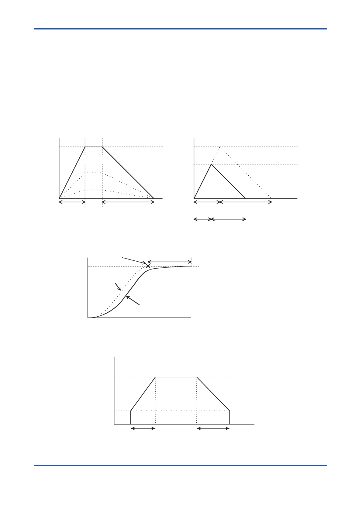
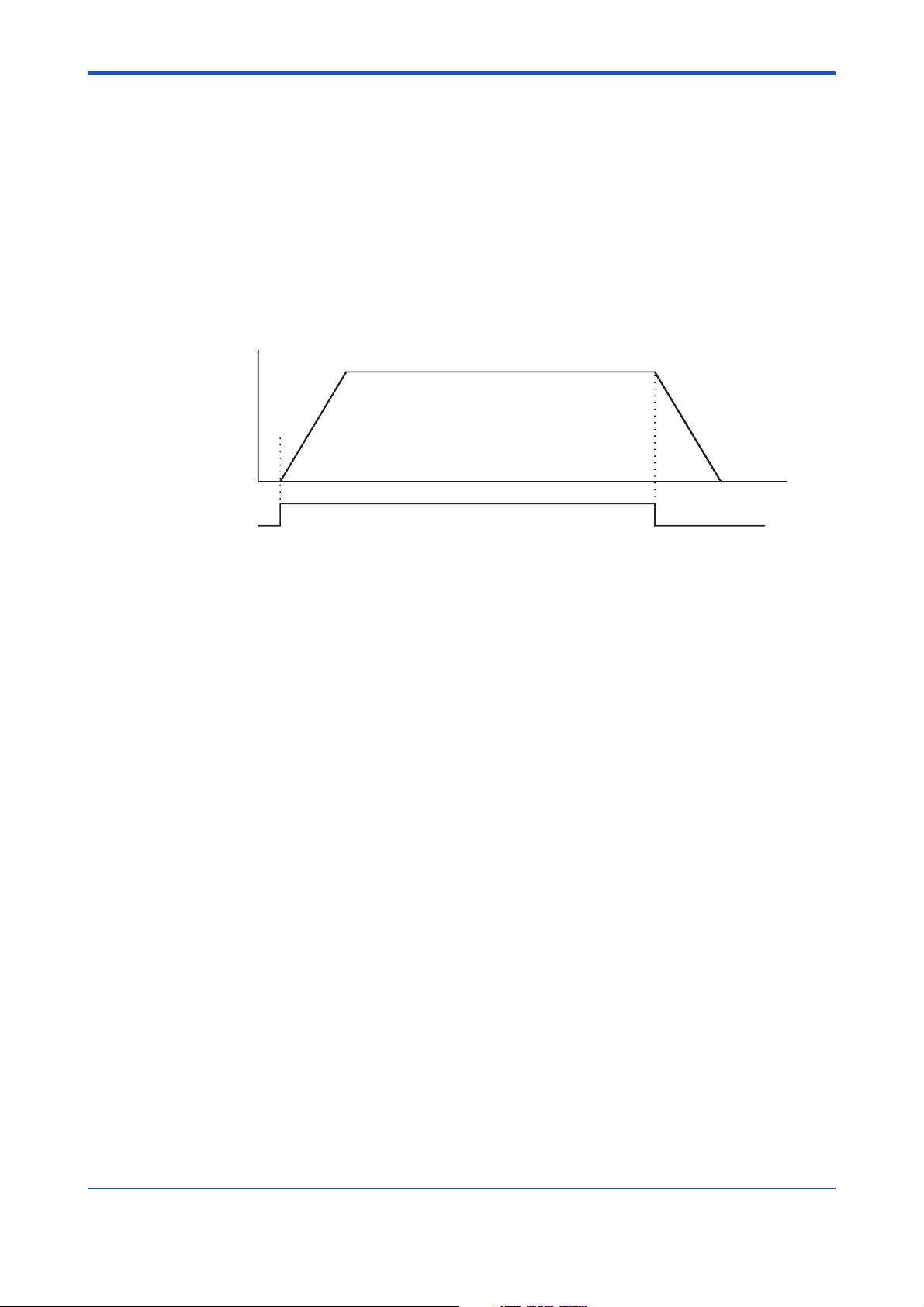
3.1 Positioning Operation
To initiate the positioning operation:
- first write the target velocity, target position, acceleration time, deceleration time and
other necessary parameters from the CPU module,
- Set the command code to 0,
- change the state of the output relay defined as “Execute Command” from off to on.
When the positioning operation is completed, the input relay defined as “End of Positioning”
turns on. The trace of the acceleration/deceleration curve is trapezoidal, and the acceleration/deceleration times are set separately.
3-2
Velocity
Acceleration
time
Velocity
Tr av e l
Target velocity
Deceleration time
Time
Tr av e l
Acceleration
time
Deceleration time
Target velocity
Actual velocity reached
Time
Actual acceleration/deceration times
F0301.EPS
Figure 3.1 Velocity and Acceleration/Deceleration Times in Trapezoidal and Trigonometric Drives
Position
Position-command
pulse count
End of positioning
Delay before target
position is reached
Motor position
Time
F0302.EPS
Figure 3.2 Comparison Between the Theoretical and Actual Behaviors of a Servo Motor in
Position Control
Velocity
Target velocity
Starting velocity
Time
Acceleration time Deceleration time
F0303.EPS
Figure 3.3 Acceleration/Deceleration Times Where Starting Velocity Is Set
IM 34M6H55-01E 3rd Edition : Apr 1, 2002-00
Page 22
3.2 Jog Stepping
j
To carry out jog stepping:
- first write the target velocity, acceleration time, deceleration time and other necessary
parameters from the CPU module, and then
- change the state of the output relay labeled “Positive-direction jog stepping” or “Nega-
tive-direction jog stepping” from off to on.
To quit the jog-stepping operation, turn the output relay off.
During jog stepping, errors in the positive-direction limit value or negative-direction limit
value are not detected. (No error occurs).
Velocity
Start
Positive-direction
og stepping
Figure 3.4 Jog-stepping Operation (Positive Direction)
3-3
End
Time
F0304.EPS
3.3 Contact Inputs
The positioning module has three external contact inputs defined as “POSITIVEDIRECTION LIMIT,” “NEGATIVE-DIRECTION LIMIT,” and “ORIGIN” for each axis.
You can read the state of each contact input using an application program. In addition, you
can set the polarity of each contact input separately.
3.4 Z-phase Encoder Input
For improved repeatability in origin searches, you can use Z-phase encoder input. You can
read the state of the encoder input the same way you read the states of a contact input.
IM 34M6H55-01E 3rd Edition : Apr 1, 2002-00
Page 23

3.5 Origin Search
To start an origin search:
- first write the velocity set point, the direction of the origin search, the origin search
mode (operation on detecting an external contact input), Z-phase edge selection, and
other necessary parameters,
- set the command code to 2,
- change the state of the output relay defined as “Execute Command” from off to on
If the positioning module detects a change in the state of a preset external contact input
after the start of the origin search operation, the module either stops the motor or checks
the Z-phase, depending on the setting of the origin search mode.
When checking the Z-phase, once the module detects the preset Z-phase pulse count, it
immediately stops the motor. The position where the motor stops is defined as the origin
(position “0”). At that point, it outputs the deviation pulse clear signal according to the time
specified in the deviation pulse clear time parameter. When the Z-phase pulse count is set
to 0, it does not output a deviation pulse clear signal.
There is an application where an origin search is carried out at two different speeds or a
change is made to the direction of rotation while checking for an external contact input
during the origin search. In such a case, split the origin search process into several cycles
while varying the parameters for each cycle, and then do the search. This strategy enables
you to customize your origin-search operation to follow your desired search patterns.
3-4
Please refer to the following page for information on the origin search mode.
IM 34M6H55-01E 3rd Edition : Apr 1, 2002-00
Page 24
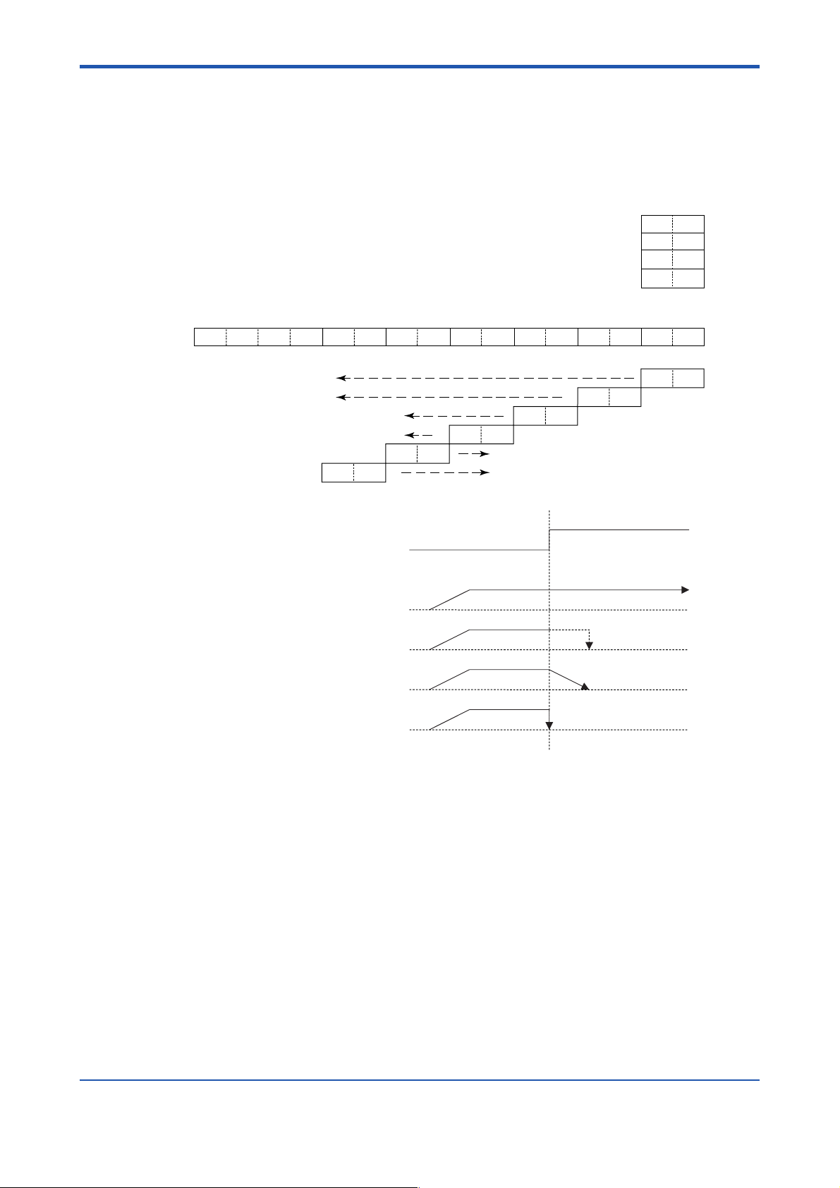
■ Details on Origin Search Mode
Sets the operation of each contact input when an edge is detected using bit combinations.
Four 2-bit combinations can be set for each rising/falling edge of an external contact input.
Bits 12 to 15 are fixed at 0.
If all bits are 0, it shifts to a Z-phase search after the start of the origin search.
3-5
Ignore (error and stop at the rising edge of the limit input in the direction of operation)
Shift to Z-phase
Decelerate and stop
Immediate stop
0000
Fall in origin input
Rise in origin input
Fall in positive-direction limit input
Rise in positive-direction limit input
For rise in contact input
When “ignore” is specified
NU0NU1
NU0NU1
ND0ND1
ND0ND1
PU0PU1
PU0PU1
Fall in negative-direction limit input
Rise in negative-direction limit input
PD0PD1
PD0PD1
OU0OU1
OU0OU1
0
0
0
1
1
0
1
1
0123456789101112131415
OD0OD1
OD0OD1
When a “Z-phase search” is specified
When the “decelerate and stop” is specified
When “stop immediately” is specified
Figure 3.5 Origin Search Operation
Stop when Z-phase is detected
F0305.EPS
IM 34M6H55-01E 3rd Edition : Apr 1, 2002-00
Page 25
3.6 Deviation Pulse Clear Signal Output
In an origin search using a servo driver, this outputs a deviation pulse clear signal at the
end of the origin search to the servo driver. It is connected to the deviation pulse clear
signal input of the servo driver.
The time period to output the deviation pulse clear signal is set in a parameter.
When the Z-phase pulse count is set to 0, a deviation pulse clear signal is not output.
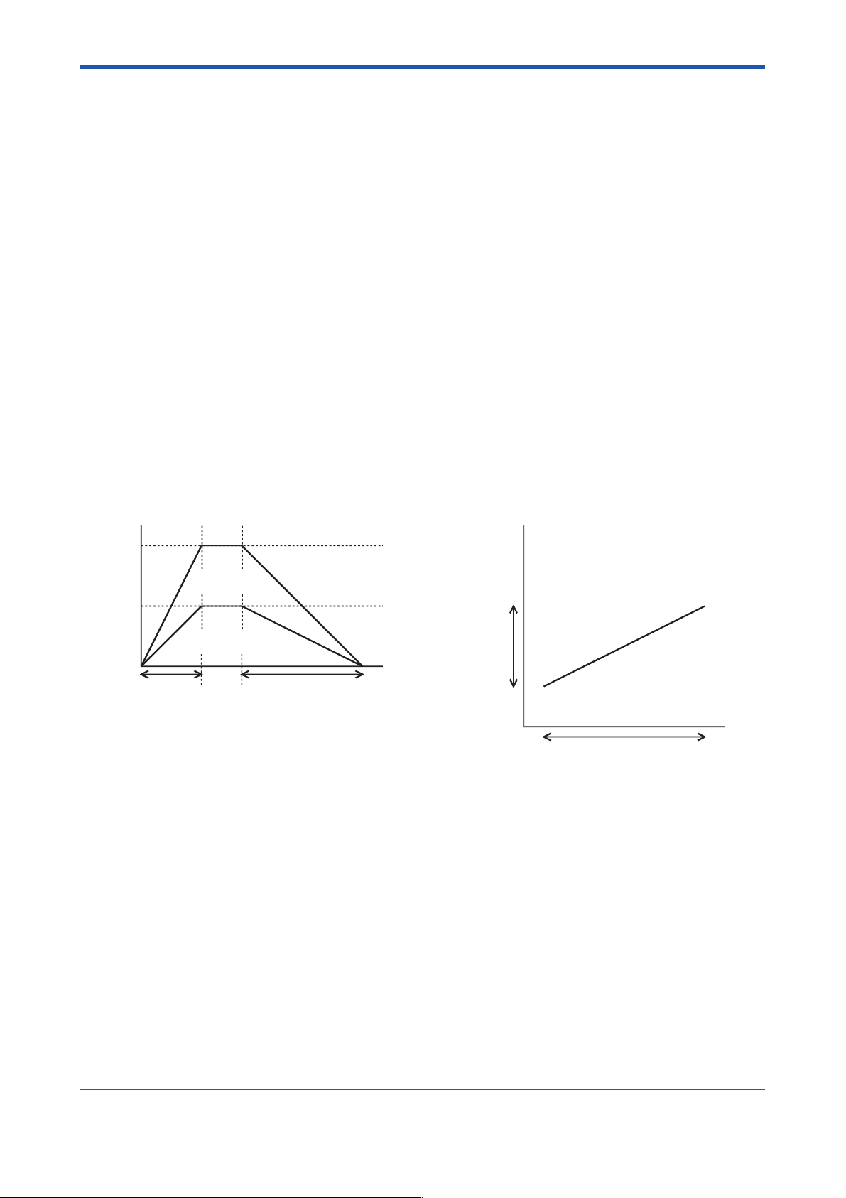
3.7 Linear-Interpolated Operation
To carry out a linear-interpolated operation:
- first write the target velocity, target position, acceleration time, deceleration time and
other necessary parameters for each axis from the CPU module,
- Set the command code to “0,”
- change the state of the output relay defined as “Execute Command” from off to on for
all axes simultaneously. When the positioning operation for each axis is completed, the
input relay defined as “End of Positioning” for each axis turns on.
In this operation, set the same acceleration and deceleration times to all axes concerned.
Calculate and set the ratio between the target velocities of the two axes so that it equals the
ratio between the travels of the two axes.
3-6
Velocity
Acceleration time
Figure 3.6 Multi-axial Linear-interpolated Operation (Example of Biaxial Application)
X-axis travel
Y-axis travel
Y-axis
X-axis target velocity
Y-axis target velocity
Y-axis
travel
Time
Deceleration time
X-axis
X-axis travel
F0306.EPS
IM 34M6H55-01E 3rd Edition : Apr 1, 2002-00
Page 26

4. Parameters
4.1 Parameters
Among the parameters listed in Tables 4.2 and 4.3, the ones with two data position numbers are 2 word data. The data item with the smaller number is the low-order word, and the
one with the larger number is the high-order word.
Data position numbers are three-digit numbers and the leading * symbol is the value of
(axis number - 1). The values from the first axis to the eighth axis are 0 to 7 respectively.
Data position numbers each correspond to a word. The WRITE and READ instructions
used to access from a sequence program must be on a word-basis. Long-word-based
instructions cause unexpected results. You should also use word-based instructions when
you access from BASIC programs.
In speed-related data, data whose setting units are [(1/65536) pulses/ms] are fixed point
data with 1-word integers (16 bits) and 1-word fractions (16 bits). The data item with the
smaller number is the low-order word, and the one with the larger number is the high-order
word.
4-1
■ Fixed-point data
The higher digits for the integer part of the binary data are sequentially defined as 1, 2, 4 ...
in value, and the lower digits for the fraction part are defined as 1/2, 1/4, 1/8, and so forth in
value. If both the integer and the fraction parts consist of 16 bits, the least significant bit for
the fraction part is 1/65536, which means that it is 32-bit (long-word) data whose setting
unit is 1/65536. Negative numbers are expressed as complements of 2 like ordinary binary
data.
Table 4.1
Bit 31(MSB) 30 ... 17 16 15 14 ... 1 0(LSB)
Value sign bit 16384 ... 2 1 1/2 1/4 ... 1/32768 1/65536
(Example of fixed point data)
When setting 123.45 [pulse/s] (=123450 [pulses/s]),
123.45x65536 = 8090419.2 [(1/65536) pulses/ms]
Thus, we should set 8090419 as long-word data. The high-order word of this data is 123
because 8090419 ÷ 65536 = 123. The low-order word is the remainder, i.e., 29491.
High-order word Low-order word
T0401.EPS
IM 34M6H55-01E 3rd Edition : Apr 1, 2002-00
Page 27

4-2
(Reference)
Example of a sequence program which converts data in [pulses/s] into data to be set for a
positioning module ([(1/65536) pulses/ms])
Let D0001 (long-word data) be the original data ([pulses/s]).
(1) Divide D0001 by 1000 (long-word division) and put the result into D0011. In this case,
since the maximum value of D0001 is 250000 (250000 pps) and it is positive, the
maximum value of the result is 250 and, thus, the high-order word (D0012) is always 0.
The low-order word of the result of the division (D0011) is the high-order word (the
integer which is 16 bits long) of the value ([(1/65536) pulses/ms]) to be set in the
positioning module.
The remainder is put into D0013 (the low-order word) and D0014 (the high-order
word). Since the maximum value of the remainder is 999 because the divisor is 1000,
the high-order word of the remainder (D0014) is always 0.
(2) Multiply the remainder by 65536 and divide it again by 1000. A useful trick here is this:
the remainder is in D0013 and D0012 is 0; thus, if D0012 is treated as long-word data,
its value is already the result of multiplying of the remainder by 65536. Therefore, in
order to divide the result of multiplying the remainder by 65536 by 1000, it is only
necessary to divide D0012 by 1000 (long-word division). Put the result of this division
into D0021.
D0012 (long word) is 999*65536 at most; dividing by 1000 is 65470 at most and the
high-order word (D0022) always becomes 0. Thus, D0021 is a low-order word (the
fraction of 16 bits) of data [(1/65536) pulses/ms] to be set in the positioning module
and the remainder is truncated.
(3) Combine the results of D0011 and D0021 into long-word data ([(1/65536) pulses/ms]).
To do this, it is only necessary to do long-word division twice and transfer the resulting
high-order and low-order words to D0032 and D0031, respectively. D0011-D0014 and
D0021-D0024 are work areas.
IM 34M6H55-01E 3rd Edition : Apr 1, 2002-00
Page 28

(1) Long-word division
D0011 = D0001 ÷ 1000
FC0401_1.EPS
Computation results
D0014 D0013 D0012 D0011
0
Remainder
0
High-order of set data
(2) Long-word division
D0021 = D0012 ÷ 1000
FC0401_2.EPS
Computation results
D0024 D0023 D0022 D0021
0
Remainder
0
Low-order of set data
(3) Data transfer
4-3
TC0401_1.EPS
TC0401_2.EPS
MOV D0011 D0032
MOV D0021 D0031
FC0401_3.EPS
Computation results
D0032
High-order set data
D0031
Low-order set data
TC0401_3.EPS
In the case of 123450 [pulses/s]
(1) D0011 = 123450/1000 (long-word division)
D0014 D0013 D0012 D0011
0 450
0 123
29491200 (= 450 × 65536)
TC0401_4.EPS
(2) D0021 = 29491200/1000 (long-word division)
D0014 D0013 D0012 D0011
0 200 0 29491
TC0401_5.EPS
From the results, the high-order word of the long-word data ([(1/65536) pulses/ms]) to
be set in the positioning module is 123, and the low-order word is 29491.
IM 34M6H55-01E 3rd Edition : Apr 1, 2002-00
Page 29

4.1.1 Entry Parameters
Entry parameters are usually set only once after turning the power on. You can set them by
writing from the CPU module and then executing the Set Parameter command. Be sure to
set all the parameters.
When the power supply is cut off, entry parameters are cleared and it is necessary to set
the parameters again.
Table 4.2 Entry parameters
4-4
Data Position
Number
01 Contact Input Polarity 0 to 7
*
02/*03 Positive-direction Limit Value –134217728 to 134217727 [pulses]
*
04/*05 Negative-direction Limit Value –134217728 to positive-direction limit value-1 [pulses]
*
is the value of (axis number - 1). The values from the first axis to the eighth axis are 0 to 7 respectively.
*
Parameter Range of values
4.1.2 Command Parameters
These are parameters to be set when executing a command. It is necessary to write all the
required parameters when executing a command.
Table 4.3 Command Parameters
Data Position
Number
11 Command Code 0 to 5
*
12 Target Position Mode 0: absolute position; 1: relative position
*
13/*14 Target Position Negative-direction limit value to positive-direction
*
15/*16 Target Velocity 1 to 16384000 [(1/65536) pulses/ms]
*
17 Acceleration Time 0 to 32767 [ms]
*
18 Deceleration Time 0 to 32767 [ms]
*
19/*20 Start Up Velocity 0 to set velocity [(1/65536) pulses/ms]
*
21 Origin Search Mode 0 to 4095
*
22 Origin Search Direction 0: Negative Direction; 1: Positive Direction
*
23 Z-phase Edge Selection 0: OFF→ON edge; 1: ON→OFF edge
*
24 Z-phase Search Count 0 to 32767 [times]
*
25/*26 Z-phase Search Range 0 to 134217727/Z-phase search count [pulses]
*
27 Deviation Pulse Clear Time 0 to 32767 [ms]
*
is the value of (axis number - 1). The values from the first axis to the eight axis are 0 to 7 respectively.
*
Parameter Range of values
T0402.EPS
limit value [pulse]
T0403.EPS
IM 34M6H55-01E 3rd Edition : Apr 1, 2002-00
Page 30

4-5
●
●
●
●
4.2 Parameters Required for Each Command
To execute a command for the positioning module from the CPU module, it is necessary to
write all the required parameters in advance.
The table below shows the required parameters for each command.
The Set Parameter command is not included in this table because it changes all the entry
parameters.
Table 4.4 Parameters Required for Each Command
Command (output relay)
Positivedirection
Jog
Data
Position
Number
11 Command code ●●— ●●— ●
*
12 Target position mode ● —— ————
*
13/*14 Target position ● —— ● ———
*
15/*16 Target velocity ●●●————
*
17 Acceleration time ●●●————
*
18 Deceleration time ●●●————
*
19/*20 Starting velocity ●●●————
*
21 Origin search mode — ● —————
*
22 Origin search direction — ● — ————
*
23 Z-phase edge selection —
*
24 Z-phase search count —
*
25/*26 Z-phase search range —
*
27
*
Parameter
Deviation pluse clear time
is the value of (axis number - 1). The values from the first axis to the eighth axis are 0 to 7 respectively.
*
● : Required parameters.
: Parameters that are required or not depending on the values of the other parameters.
—: Non-required parameters (have no effect on the operation of the commands if used).
Start
Positioning
Command
—
Origin
Search
Command
Stepping
Command
Negative-
direction
Jog
Stepping
Command
—————
—————
—————
—————
Set
Current
Position
Command
Decelerate
& Step
Command
Stop
Immediately
Command
Error
Reset
Command
T0404.EPS
IM 34M6H55-01E 3rd Edition : Apr 1, 2002-00
Page 31

4.3 Descriptions of Parameters
4.3.1 Entry Parameters
When the power is switched on, all entry parameters are cleared. Set all entry parameters
using the Set Parameter command in an application program. When a set parameter value
is invalid, an Error Notification input relay is set, and a setting error in the entry parameter
results. When this happens, execute Error Reset and execute the Set Parameter command
again with valid values.
Table 4.5 Entry parameters
Parameter
Type
(Data Position
Number)
What the set
parameter does
Data Range Remarks
4-6
Contact input
polarity
(
01)
*
Positivedirection limit
value
(
02/*03)
*
Negativedirection limit
value
(
04/*05)
*
Defines the logic of
the external
contact input.
Sets the operation
limit position in the
positive direction
as the number of
pulses from the
origin.
Sets the operation
limit position in the
negative direction
as the number of
pulses from the
origin.
Specified for each contact
input as a bit. “0” indicates an
“a” contact and “1” indicates a
“b” contact.
Bit 0: Negative-direction limit
input
Bit 1: Positive-direction limit
input
Bit 2: Origin position input
–134217728 to 134217727
[pulses]
–134217728 to Positivedirection limit value-1 [pulses]
An “a” contact input is an input
which is effective when a signal
input exists, and a “b” contact
input is an input which is
effective without a signal input .
For example, a “limit input of ‘b’
contact” detects the limit when
there is no signal input, but
does not detect the limit when a
signal input exists.
If an origin search is not
executed, then the position at
the moment when the main
switch is turned on is defined as
the origin. If you start the
system after setting a target
position beyond this range, an
error results and the motor does
not start.
Detection of the limit values is
not performed during an origin
search or jog stepping. (An
error does not occur.)
T0405.EPS
IM 34M6H55-01E 3rd Edition : Apr 1, 2002-00
Page 32

4.3.2 Command Parameters
Table 4.6 Command Parameters
Parameter
Type
(Data Position
Number)
What the set
parameter does
4-7
Data Range Remarks
Command
Code
(
11)
*
Target
Position
Mode
(
12)
*
Target
Position
(
13/*14)
*
Target
Velocity
(
15/*16)
*
Acceleration
Time
(
17)
*
Deceleration
Time
(
18)
*
Starting
Velocity
(
19/*20)
*
Sets the command type
for the command
execution using the
Execute Command Relay.
Sets the types of Target
positions
Sets the target position for
the positioning operation,
or the current position.
Sets the operation velocity
in position control, origin
position search and jog
stepping.
Sets the time it takes to
reach the target velocity
from the Starting velocity.
Sets the time from the
target velocity to
Decelerate and Stop.
This is the starting velocity
of the operation at the
start of the positioning
operation and the velocity
just before stopping at the
end of Positioning.
0: Start Positioning command
1: Decelerate-and-Stop
command
2: Origin Search command
3: Set Parameter command
4: Set Current Position
command
5: Error Reset command
0:Absolute position,
1:Relative position
Negative-direction limit value
to Positive-direction limit
value [pulse]
1 to 16384000 [(1/65536)
pulses/ms]
0 to 32767 [ms]
0 to 32767 [ms]
0 to target velocity [(1/65536)
pulses/ms]
If the value of the target velocity specified
is smaller than the Starting velocity, an
error occurs.
When using a pulse motor and
accelerating from the velocity [0],
resonance may occur resulting in out of
phase at the low velocity portion during
acceleration. (The situation is the same
for deceleration). Set a velocity faster
than the resonance point to prevent this
from happening. However, you should
take note that too large a setting may
cause the moter to be out of phase at
startup or stop because of impact.
When using a servo motor, it is normally
set to [0].
Origin-search
Mode
(
21)
*
Origin-search
Direction
(
22)
*
Sets the motion of the
motor for each contact
input after detecting the
edges of each contact
input during an origin
search using bit patterns.
Sets the motor rotation
direction during an origin
search.
0 to 4095
0: Negative -direction,
1: Positive-direction
For details, refer to Section 3.5, “Originsearch Operation.”
T0406_1.EPS
IM 34M6H55-01E 3rd Edition : Apr 1, 2002-00
Page 33

Parameter
Type
(Data Position
Number)
What the set
parameter does
4-8
Data Range Remarks
Z-phase
Edge
Selection
(
23)
*
Z-phase
Search Count
(
24)
*
Z-phase
Search
Range
(
25/*26)
*
Deviation
Pulse Clear
Time
(
27)
*
Sets the Z-phase edge
direction when detecting
the Z-phase during an
origin search.
Sets the number of Zphase pulses to be
counted during origin
search fefore an origin
can be established.
Error occurs if a Z-phase
cannot be detected even
after the search exceeds
the Z-phase search range.
Sets the output time of the
deviation pulse clear
signal when the origin
search ends because of a
Z-phase detection.
0: OFF→ON edge
1: ON→OFF edge
0 to 32767 [times]
0 to 134217727/Z-phase
search count [pulses]
0 to 32767 [ms]
This parameter is used to prevent
continued operation when a Z-phase
cannot be detected because of a Z-phase
signal disconnection, etc. Usually, this is
set close to the number of pulses between
two Z-phase pulses.
T0406_2.EPS
IM 34M6H55-01E 3rd Edition : Apr 1, 2002-00
Page 34

4.4 Examples of Setting Entry Parameters
The following examples show the minimum settings of entry parameters for controlling the
motor using the positioning module. The underlined values are set.
■ The motor used
Rated rotating speed: 3000 rpm
Encoder pulse count: 1 rotation: 8192 pulses
CAUTION
You can set/change the ratio of the command pulses and encoder pulses on the servo
driver side. In these cases, the parameters set in the positioning module must match the
setting of the servo driver. So calculate the values of the entry parameters after confirming
the setting of the servo driver.
4-9
■ Mechanism
Direct shaft drive using ball screw
Ball screw pitch: 5 mm/rot
Operation Range: –500 mm to +1000 mm
Maximum speed: 6000 mm/min (100 mm/s)
Contact Input: Positive/Negative-direction limit input (“b” contact), origin (“a” contact)
■ Calculation of entry parameters
- Contact input polarity
Positive-direction limit value ( “b” contact), Negative-direction limit input ( “b” contact),
Origin ( “a” contact) →
- Positive-direction limit value
1000 (mm) ÷ 5 (mm/rot) × 8192 (pulses/rot) =
- Negative-direction limit value
–500 (mm) ÷ 5 (mm/rot) × 8192 (pulses/rot) =
Negative-direction limit
$0003
1638400 (pulses)
–819200 (pulses)
Positive-direction limitOrigin Negative Positive
500 mm 1000 mm
Figure 4.1 Direct Shaft Drive Using Ball Screw
F0401.EPS
IM 34M6H55-01E 3rd Edition : Apr 1, 2002-00
Page 35

Blank Page
Page 36

5. Status
Statuses are the data which the CPU module reads from the positioning module. You can
check the state of the positioning module using these statuses and input relays.
CAUTION
When the CPU module reads 2-word data from the positioning module, the high-order
word/low-order word of 2-word data is not guaranteed to be concurrent due to a conflict
between the reading timing of the CPU module and the data update period of the positioning module.
In reading from the sequence CPU, to ensure that the high-order word and low-order word
of 2-word data are concurrent, use the READ command to read the data twice consecutively and verify that the data read are the same in both instances. In this situation, if the
HRD command is used, data concurrency cannot be guaranteed even if you confirm that
the data are the same.
In reading from the BASIC CPU, concurrency is not guaranteed because the time required
to read 2-word data is longer than the data update period of the positioning module.
5-1
IM 34M6H55-01E 3rd Edition : Apr 1, 2002-00
Page 37

5.1 List of Status
In Table 5.1, the statuses listed with 2 data position numbers are 2-word data. The data item
with the smaller number is the low-order word, and the one with the larger number is the
high-order word.
5-2
The data position number consists of three digits, the leading
is the value of (axis num-
*
ber-1). Insert the values 0 to 7 for axes 1 to 8 respectively.
Data position numbers are specified for each word. The READ instruction used for access
from a sequence program must be on a word basis. Long-word-based instructions cause
unexpected results.
Use word-wise instructions also when accessing from a BASIC program.
Speed-related data, data with a setting unit [(1/65536) pulses/ms], are fixed-point data with
a 1-word (16 bits) integer and a 1-word (16 bits) fraction. The data with the smaller number
is the low-order word, and the one with the larger number is the high-order word. For more
information on fixed-point data, refer to the description of fixed point data in Section 4.1,
“Parameters.”
(Reference)
To convert data in [(1/65536) pulses/ms] units into data in [pulses/sec] units, multiply the
data by 1000 in a long Operation Result word operation, ignore the lowest-order word and
the highest-order word and use the second and the third words as long-word data.
(Example)
Let D0001 be long-word data in [(1/65536) pulses/ms] units. The operation is as follows.
D0011 = D0001
D0014 D0013 D0012 D0011
0
Resulting long word [pulses/ms] Truncated Portion
*
1000
FC0501.EPS
TC0501.EPS
Table 5.1 Statuses
Data Position
Number
51/*52 Target Position Status –134217728 to 134217727 [pulses]
*
53/*54 Current Position Status –134217728 to 134217727 [pulses]
*
55/*56 Current Velocity Status 0 to 16384000 [(1/65536) pulses/ms]
*
57 Contact Input Status States of contact inputs
*
58 Error Status Error information when an error occurs
*
59 Origin Search Status Status related to an origin search
*
is the value of (Axis number - 1). The values of axis1 to axis 8 are 0 to 7, respectively.
*
Status Range of values
T0501.EPS
IM 34M6H55-01E 3rd Edition : Apr 1, 2002-00
Page 38

5.2 Description of Status
Table 5.2 Statuses
5-3
Data Position
Number
51/*52 Target Position Status
*
53/*54 Current Position
*
55/*56 Current Velocity
*
57 Contact Input Status Reads the state of the external contact input and the
*
58 Error Status Reads the error code when an error occurs. It is
*
[pulses]
Status [pulses]
Status [(1/65536)
pulses/ms]
Status Data Contents
Reads the operation target position during a positioning
operation. The target position which is set at the start of the
positioning is stored as the operation target position.
This represents the current position of the positioning
module output. Therefore, it is not the actual motor position
when the servomotor is used.
Reads the current velocity status, which is the current
velocity of the output pulse of the positioning module.
Therefore, it is not the actual velocity of the motor when the
servomotor is used. Regardless of the direction of the
motor’s rotation, the value is zero or positive.
encoder Z-phase input. The state of each contact is stored
as 1 bit (0: off; 1: on). When a contact is specified as an “a”
contact, it is represented by “1” if the contact is closed.
When a contact is specified as a “b” contact, it is
represented by “1” if the contact is opened.
bit 0: negative-direction limit input
bit 1: positive-direction limit input
bit 2: origin input
bit 3: encoder Z-phase input
meaningless if the relay labeled “Error Notification” is off.
For details, refer to Section 8.2, “Error Codes.”
59 Origin Search Status Reads the status during an origin search and at the end of
*
is the value of (axis number - 1). The values of axis 1 to 8 are 0 to 7, respectively.
*
an origin search.
0: On power-up or when at normal end of the origin search
1: Stops when the input edge of “Stop immediately” or
“Decelerate and Stop” command setting is detected.
2: Stopped by a “Stop immediately” or “Decelerate and
Stop” command.
3: Stopped by an error
4: During a Z-phase search
5: Before a Z-phase search
T0502.EPS
IM 34M6H55-01E 3rd Edition : Apr 1, 2002-00
Page 39

Blank Page
Page 40

6. Input/Output Relays
The positioning module has 32 output relays and 32 input relays as the interface to the
FA-M3 CPU module. For details on each input/output relay, refer to Chapter 7, “Accessing
Modules.”
CAUTION
In the F3YP04-0N, NEVER set the output relays related to axes 5 to 8 (Y49 to
Y64).
Further, input relays related to axes 5 to 8 (X17 to X32) are meaningless.
6.1 Output Relays
Table 6.1 Output Relays
6-1
Output
relay
number
Y33 Axis 1 Execute Command Y49 Axis 5 Execute Command
Y34 Axis 1 Stop Immediately Y50 Axis 5 Stop Immediately
Y35 Axis 1 Positive-direction Jog Stepping Y51 Axis 5 Positive-direction Jog Stepping
Y36 Axis 1 Negative-direction Jog Stepping Y52 Axis 5 Negative-direction Jog Stepping
Y37 Axis 2 Execute Command Y53 Axis 6 Execute Command
Y38 Axis 2 Stop Immediately Y54 Axis 6 Stop Immediately
Y39 Axis 2 Positive-direction Jog Stepping Y55 Axis 6 Positive-direction Jog Stepping
Y40 Axis 2 Negative-direction Jog Stepping Y56 Axis 6 Negative-direction Jog Stepping
Y41 Axis 3 Execute Command Y57 Axis 7 Execute Command
Y42 Axis 3 Stop Immediately Y58 Axis 7 Stop Immediately
Y43 Axis 3 Positive-direction Jog Stepping Y59 Axis 7 Positive-direction Jog Stepping
Y44 Axis 3 Negative-direction Jog Stepping Y60 Axis 7 Negative-direction Jog Stepping
Y45 Axis 4 Execute Command Y61 Axis 8 Execute Command
Y46 Axis 4 Stop Immediately Y62 Axis 8 Stop Immediately
Y47 Axis 4 Positive-direction Jog Stepping Y63 Axis 8 Positive-direction Jog Stepping
Y48 Axis 4 Negative-direction Jog Stepping Y64 Axis 8 Negative-direction Jog Stepping
(Note) Insert into the empty boxes above () the number of the FA-M3 slot where this module is installed.
Operation when ON
Output
relay
number
Operation when ON
T0601.EPS
IM 34M6H55-01E 3rd Edition : Apr 1, 2002-00
Page 41

6.2 Input Relays
Table 6.2 Input Relays
6-2
Input
relay
number
X01 Axis 1 Execute Command ACK X17 Axis 5 Execute Command ACK
X02 Axis 1 Stop Immediately ACK X18 Axis 5 Stop Immediately ACK
X03 Axis 1 Error Notification X19 Axis 5 Error Notification
X04 Axis 1 End of Positioning X20 Axis 5 End of Positioning
X05 Axis 2 Execute Command ACK X21 Axis 6 Execute Command ACK
X06 Axis 2 Stop Immediately ACK X22 Axis 6 Stop Immediately ACK
X07 Axis 2 Error Notification X23 Axis 6 Error Notification
X08 Axis 2 End of Positioning X24 Axis 6 End of Positioning
X09 Axis 3 Execute Command ACK X25 Axis 7 Execute Command ACK
X10 Axis 3 Stop Immediately ACK X26 Axis 7 Stop Immediately ACK
X11 Axis 3 Error Notification X27 Axis 7 Error Notification
X12 Axis 3 End of Positioning X28 Axis 7 End of Positioning
X13 Axis 4 Execute Command ACK X29 Axis 8 Execute Command ACK
X14 Axis 4 Stop Immediately ACK X30 Axis 8 Stop Immediately ACK
X15 Axis 4 Error Notification X31 Axis 8 Error Notification
X16 Axis 4 End of Positioning X32 Axis 8 End of Positioning
(Note) Insert into the empty boxes above () the number of the FA-M3 slot where this module is installed.
Operation when ON
Input
relay
number
Operation when ON
T0602.EPS
IM 34M6H55-01E 3rd Edition : Apr 1, 2002-00
Page 42

7. Accessing Modules
In the program examples shown in this chapter, the positioning module is installed in the
4th slot (slot #004) of the main unit; when only one axis is used in these examples, it will be
axis 1.
7.1 Accessing from the Sequence CPU
The following are the instructions to access from the sequence CPU with the ladder sequence program. The details for each instruction are explained in the “Sequence CPU
Instruction Manual — Instructions” (IM34M6P12-03E).
■ Reading/Writing Parameters and Statuses
The instructions should be in word units. Long-word unit instructions cannot be used.
• Special Module Read Instruction (READ Instruction)
kDn1SLREAD
FC0701_1.EPS
SL: number of slot where the module is installed
7-1
n1: first data position number for reading data
D: first device to store the read data
k: number of data (in word units) to be read
• Special Module Write Instruction (WRITE Instruction)
kn2SLSWRITE
FC0701_2.EPS
S: device in which to store the write data
SL: number of slot where the module is installed
n2: first data position number for the write data
k: number of data (in word unit) to be written
• Special Module High-Speed Read Instruction (HRD Instruction)
kDn1SLHRD
FC0701_3.EPS
SL: number of slot where the module is installed
n1: first data position number for reading data
D: first device in which to store the read data
k: number of data (in word units) to be read
• Special Module High-Speed Write Instruction (HWR Instruction)
kn2SLSHWR
FC0701_4.EPS
S: device in which to store the write data
SL: number of slot where the module is installed
n2: first data position number for the write data
k: number of data (in word units) to be written
IM 34M6H55-01E 3rd Edition : Apr 1, 2002-00
Page 43

7.1.1 Reading the Module Status
This section explains how to read the status of the positioning module.
Item to Note
- The status of the positioning module can be read at any time. Take care when reading
the long-word data. Refer to Chapter 5, “Statuses.”
Program Example
In the example below, all of the statuses are read at the same time using a READ instruction.
● Major devices used
D0051/D0052 Read the target position status
D0053/D0054 Read the current position status
D0055/D0056 Read the current velocity status
D0057 Read the contact input status
D0058 Read the error status
D0059 Read the origin search status
D0121/D0122 Current Velocity [pulses/s]
D0131 to D0134 (Computation Work Area)
I00001 to I00016 Bit Data of Contact Input
7-2
TC070101.EPS
(0001)
(0002)
00001
(0003)
(0004)
(0005)
Module Status Reading Program
M0033
READ 5149
D0131 D0055
Figure 7.1 Module Status Reading Program
Status Read
D0051
Contact Input
MOV
=
MOV
D0057
D0132
I00001
*
1000
D0121
Expansion
Change Current
Velocity
Pulses/s
F0701.EPS
IM 34M6H55-01E 3rd Edition : Apr 1, 2002-00
Page 44

7.1.2 Set Parameter
This sets the entry parameters.
Items to Note
- This command is accepted only if both of the following conditions are satisfied: (1) the
positioning module is in the End of Positioning status and (2) no other commands are
being executed. If these conditions are not satisfied, then the command will be ignored.
- An error cannot be reset with the Error Reset command if the error occurs with the Set
Parameter command (error code 2uuu). Run the Set Parameter command again
with proper data.
Procedure:
1) Write setting parameters and command codes on the positioning module with the
WRITE command.
2) Set the Execute Command output relay.
3) Reset the Execute Command output relay after confirming that the Execute Command
ACK input relay is set. If there is an entry parameter setting error, the Execute Command ACK input relay is not set, but the Error Notification input relay is set. In this
case, reset the Execute Command output relay, and then go back and repeat from
step 1.
7-3
4) Check that the Execute Command ACK is reset.
Program Example:
In this example, parameters are set in the data register in advance. All entry parameters will
be written at once with the WRITE instruction.
● Major devices used
D0001 Contact Input Polarity
D0002/D0003 Positive-direction Limit Value
D0004/D0005 Negative-direction Limit Value
Y00433 Execute Command (Output Relay)
X00433 Execute Command ACK (Input Relay)
I00099 Command Execution Prohibit Condition (set elsewhere)
I00101 Request to Execute Command
I00102 Request to Execute Command (Rising Edge)
I00103 Waiting for Command ACK
I00104 Executing Command
I00105 Forced Reset of Set Parameter
TC070102.EPS
IM 34M6H55-01E 3rd Edition : Apr 1, 2002-00
Page 45

7-4
(0001)
(0002)
00001
(0003)
00003
(0004)
(0005)
(0006)
(0007)
(0008)
00015
(0009)
(0010)
00024
Parameter Setting Program
I00101
I00102 I00099
I00103 Y00433 X00401
I00105
I00104 I00103 X00401
Figure 7.2 Parameter Setting Program
DIFU
WRITE D0001 4 1 5
WRITE 43111
SET
SET
SET
RST
RST
RST
I00102
Y00433
I00103
I00104
Y00433
I00103
I00104
F0702.EPS
I00101
I00102
I00103
I00104
Y00433
X00401
F0703.EPS
Figure 7.3 Parameter Setting Program Time Chart
IM 34M6H55-01E 3rd Edition : Apr 1, 2002-00
Page 46

7.1.3 Error Reset
This resets the error status of the positioning module.
Item to Note:
- The positioning module ignores any commands other than the Error Reset command
and Set Parameter command in an error status (i.e. the status where the Error Notification input relay is set). So be sure to execute the Error Reset command in an error
status. However, if an error occurs because of an entry parameter setting error (error
code 2) in the Set Parameter command, the error cannot be reset using the
Error Reset command. Refer to Section 7.1.2, “Parameter.”
Procedures:
1) Write the command code on the positioning module with the WRITE instruction.
2) Set the Execute Command output relay.
3) Check that the Error Notification relay is reset. Then reset the Execute Command
output relay.
7-5
Program Example:
This example assumes that the Error Reset operation is done manually. All output relays of
the positioning module are reset at the time of the Error Reset operation. The error code
remains until the completion of Error Reset.
● Major devices used
X00433 Execute Command (Output Relay)
Y00401 Execute Command ACK (Input Relay)
X00403 Error Notification (Input Relay)
I00111 Request to Reset Error (Manually Operated Signal)
I00112 Request to Reset Error (Rising Edge)
I00113 Request to Reset Error (Falling Edge)
D0201 Error Code Storage Device
TC070103.EPS
IM 34M6H55-01E 3rd Edition : Apr 1, 2002-00
Page 47

7-6
(0001)
(0002)
00001
(0003)
(0004)
00006
(0005)
(0006)
(0007)
(0008)
(0009)
(0010)
(0011)
00022
Error Reset Program
I00111
I00112 X00403
I00114
Y00433 X00401
DIFU
DIFD I00113
READ 58 D0201 1
WRITE 45
4
RST
RST
RST
SET
SET
RST
I00112
11
Y00434
Y00435
Y00436
Y00433
I00114
Y00433
1
(0012)
I00113
Figure 7.4 Error Reset Program
I00111
I00112
I00113
Y00433
X00401
X00403
Figure 7.5 Error Reset Program Time Chart
F0705.EPS
RST
I00114
F0704.EPS
IM 34M6H55-01E 3rd Edition : Apr 1, 2002-00
Page 48

7.1.4 Jog Stepping
When the Positive- (Negative-) direction Jog Stepping output relay is on, the motor rotates
in the positive (negative) direction.
Items to Note:
- This command is accepted only if all of the following conditions are satisfied: (1) it is
not in an error state, (2) it is in the End of Positioning status and (3) no other command
is being executed. Otherwise, it is ignored.
- During jog stepping the Stop Immediately command is valid, while the Decelerateand-Stop command is ignored. Terminate jog stepping first when decelerate and stop
is desired.
- During log stepping, even if the module is operating beyond the range of the “Positive(Negative-) direction limit value,” no error occurs.
Procedures:
1) Write the required parameters of the Jog Stepping command on the positioning
module with the WRITE instruction and other commands.
7-7
2) When the Positive-direction (Negative-direction) Jog Stepping output relay is set, the
motor rotates according to the parameters, and the End-of-Positioning input relay is
reset.
3) When the Positive-direction (Negative-direction) Jog Stepping output relay is reset, the
motor will decelerate and stop according to the parameters set when the jog stepping
started. After that, the End-of-positioning input relay is set.
Program Example:
In this example, jog stepping starts with the Request for Jog Stepping, and ends with the
release of the request. The jog stepping mode is reset automatically if any error occurs
during jogging. This example shows only the positive-direction case. Required parameters
are set in advance in the data registers.
● Major devices used
D0215/D0216 Target Velocity
D0217 Acceleration Time
D0218 Deceleration Time
D0219/D0220 Start Up Velocity
Y00435 Positive-direction Jog Stepping (Output Relay)
X00403 Error Notification (Input Relay)
X00404 End of Positioning (Input Rely)
I00099 Command Execution Prohibit Condition (set elsewhere)
I00121 Positive Direction Jog Stepping Request
I00122 Positive Direction Jog Stepping Request (Rising Edge)
I00123 Positive Direction Jog Stepping Request (Falling Edge)
I00124 Executing Positive-direction Jog Stepping
TC070104.EPS
IM 34M6H55-01E 3rd Edition : Apr 1, 2002-00
Page 49

7-8
(0001)
(0002)
00001
(0003)
(0004)
00006
(0005)
(0006)
(0007)
00014
(0008)
(0009)
(0010)
Jog Stepping Program
I00121
I00122 I00099
I00124 I00123 Y00435
Y00435 X00404
X00403
Figure 7.6 Jog Stepping Program
DIFU
DIFD I00123
WRITE 4D0215 15 6
SET
SET
RST
RST
RST
RST
I00122
Y00435
I00124
Y00435
I00124
Y00435
I00124
F0706.EPS
Motor Speed
I00121
I00122
I00123
I00124
Y00435
X00404
F0707.EPS
Figure 7.7 Jog Stepping Program Time Chart
IM 34M6H55-01E 3rd Edition : Apr 1, 2002-00
Page 50

7.1.5 Using Origin Search
This executes an origin search. There are three external contact inputs related to an origin
search. The origin search mode specifies the action when each rising and falling edge of
these three inputs (six in total) are detected during the origin-search using bit patterns.
(2 bits for each edge, so 12 bits in total.)
In the example below, the condition of the search is as follows. The direction of the origin
search is negative. (1) Stops immediately when the rising edge of the negative-direction
limit is detected. (2) Decelerates and stops when the rising edge of the origin input is
detected. (3) Shifts to a Z-phase search when the falling edge of the origin search is
detected. In this case, the origin search mode is set as follows (“0C09” in sexadecimal).
(For the origin search mode, refer to Section 3.5, “Origin Search.”)
0000 000000100111
7-9
Negative direction Limit input
Figure 7.8 Example of Origin Search Operation
Items to Note:
- This command is accepted only if all of the following conditions are satisfied: (1) it is
- The origin search ends when a specified external contact input is detected and the
- In the following cases, an error occurs and the search automatically stops:
Negative direction
(1) (3) (2)
Origin input
Positive direction
F0708.EPS
not in an error state, (2) it is in the End-of-Positioning status, and (3) no other command is being executed. Otherwise, it is ignored.
search is stopped. Change the parameters and begin the origin search again after it
ends if you want to continue the search in another direction or at a different speed.
- The limit input of the origin-search direction is set to be ignored but it is detected.
- After shifting to a Z-phase search, the limit input of the origin-search direction is
detected (causing an error regardless of the setting).
- After shifting to a Z-phase search, the Z-phase cannot be detected within the Z-
phase search range.
- If you want to change the setup values according to the status of the external contact
input at the beginning of the origin search, read the state with the Contact Input Status
and then execute the origin search.
- After shifting to a Z-phase search, even if the external contact input that sets the Stop
Immediately and Decelerate and Stop operation is detected, the Z-search operation
will continue. (This is different from an origin search in the F3NC11-0N and F3NC120N modules)
- During the origin search, even if the operation goes beyond the range defined by the
Positive- (Negative-) direction limit values, an error does not occur.
IM 34M6H55-01E 3rd Edition : Apr 1, 2002-00
Page 51

Procedures:
1) Write parameters and command codes required by the Origin-Search command on
the positioning module with the WRITE instruction and other commands.
2) When the output relay defined as “Execute Command” is set, the “Execute Command
ACK” input relay is set and operation starts. Operation continues until the specified
external contact input is detected. If there is an error in the parameter, the ErrorNotification Input Relay will be set but not the Execute Command ACK Input Relay.
3) When Z-phase pulses are detected for the specified number of times after shifting to a
Z-phase search (if this number is specified as ‘’0," then without shifting to a Z-phase),
the current position is specified as “Position 0” and the operation stops immediately.
After outputting the deviation pulse clear signal for a preset duration, the End of
Positioning Input relay is set.
4) By referring to the origin search status, the cause of the end of an origin search can be
determined. When the origin search status is “0,” the origin search has ended due to
the detection of a Z-phase. For details on the origin search status, refer to Section 5.2,
“Description of Statuses.”
Program Example:
This program starts the origin search using the Request to Start Origin Search and stops it
using the specified external contact input.
7-10
If any error is detected during the search, the search mode is automatically reset.
The following program also occupies the area for non-required parameters because all the
parameters are written at once.
All required parameters are set in advance in the data register.
● Major devices used
D0311 Command Code
D0312 to D0314 (unnecessary area)
D0315/D0316 Target Velocity
D0317 Acceleration Time
D0318 Deceleration Time
D0319/D0320 Start Up Velocity
D0321 Origin-search Mode
D0322 Origin-search Direction
D0323 Z-phase Edge Selection
D0324 Z-phase Search Count
D0325/D0326 Z-phase Search Range
D0327 Deviation Pulse Clear Time
D0359 Origin-Search Status
Y00433 Execute Command (Output Relay)
X00401 Execute Command ACK (Input Relay)
X00403 Error Notification (Input Relay)
X00404 End of Positioning (Input Relay)
I00099 Command Execution Prohibit Condition (set elsewhere)
I00131 Request to Search Origin
I00132 Request to Search Origin, Differentiate Up
I00133 Waiting for Command ACK
I00134 Executing Origin Search
TC070105.EPS
IM 34M6H55-01E 3rd Edition : Apr 1, 2002-00
Page 52

7-11
(0001)
(0002)
00001
(0003)
00003
(0004)
(0005)
(0006)
(0007)
00013
(0008)
(0009)
00022
(0010)
Origin-search Program
I00131
I00132 I00099
I00133 Y00433 X00401
X00403
I00134 I00133 X00401 X00404
Figure 7.9 Origin-search Program
DIFU
WRITE D0311 4 11 17
SET Y00433
SET
SET
RST
RST
RST
READ 4 59 D0359 1
I00132
I00133
I00134
Y00433
I00133
I00134
F0709.EPS
Motor Speed
Motor stops immediately at this position.
I00131
I00132
I00133
I00134
Y00433
X00401
X00404
Figure 7.10 Origin-search Program Time Chart
F0710.EPS
IM 34M6H55-01E 3rd Edition : Apr 1, 2002-00
Page 53

7.1.6 Set Current Position
This changes the current position of the axis during the End of Positioning.
Items to Note:
- This command is accepted only if all of the following conditions are satisfied: (1) it is
not in an error state, (2) it is in the End-of-Positioning status (3) no other commands
are being executed. Otherwise, it is ignored.
- The change position should fall in the range from the positive-direction limit to the
negative-direction limit. An error occurs when requesting to change beyond the limits
of the range.
- When the motor is operating, you cannot set the current position. This command is
ignored.
Procedures:
1) Write the new position and command code in the Positioning module using the WRITE
instruction.
2) Set the output relay defined as “Execute Command.”
7-12
3) Reset the relay defined as “Execute Command” after confirming that the input relay
defined as “Execute Command ACK” is set. If there is a parameter error, the input
relay defined as “Error Notification” is set but the Execute Command ACK will not be
set.
Program Example:
This is an example to set the current position. All required parameters are set in advance in
the data register.
● Major devices used
D0411 Command code
D0412 (unnecessary area)
D0413/D0414 Target Position (new current position)
Y00433 Execute Command (Output relay)
X00401 Execute Command ACK (Input relay)
X00403 Error Notification (Input relay)
I00099 Command Execution Prohibit Condition (set elsewhere)
I00141 Request to Write Current Position
I00142 Request to Write Current Position (Differentiate Up)
I00143 Waiting for Command ACK
I00144 Executing Command
TC070106.EPS
IM 34M6H55-01E 3rd Edition : Apr 1, 2002-00
Page 54

7-13
(0001)
(0002)
Current Position Setting Program
I00141
00001
(0003)
I00142 I00099
00003
(0004)
(0005)
(0006)
(0007)
I00143 Y00433 X00401
00013
(0008)
(0009)
I00144 I00143 X00401
X00403
00022
Figure 7.11 Current Position Setting Program
I00141
DIFU
I00142
WRITE D0411 4 11 4
SET Y00433
SET
SET
RST
RST
RST
I00143
I00144
Y00433
I00143
I00144
F0711.EPS
I00142
I00143
I00144
Y00433
X00401
F0712.EPS
Figure 7.12 Current Position Setting Program Time Chart
IM 34M6H55-01E 3rd Edition : Apr 1, 2002-00
Page 55

7.1.7 Positioning Operation
This executes a positioning operation towards a preset target position.
Items to Note:
- This command is accepted only if all of the following conditions are satisfied: (1) it is
not in an error state, (2) it is in the End -of -Positioning status, (3) no other commands
are being executed, If conditions are not satisfied, it is ignored.
- If an invalid value is set for a parameter, a parameter error results and the motor does
not move.
Procedures:
1) Write the required parameters and command codes in the positioning module using
the WRITE instruction.
2) Set the output relay defined as “Execute Command.”
3) The Execute Command ACK will be set and the motor starts operating. After confirming that the Execute Command ACK input relay is set, reset the Execute Command
relay. (If there is a parameter error, the Execute Command ACK input relay is not set
and the Error Notification input relay is set.).
7-14
4) The End of Positioning input relay is set when the output pulse count reaches the
target position. In general, when using servomotors, there is some time lag between
the stopping of the pulse output and the stopping of the motor after reaching the target
position. Take note of this time lag.
Program Example:
This is a sample program of a positioning operation. All required parameters are set in
advance in the data register.
● Major devices used
D0511 Command Code
D0512 Target Position Mode
D0513/D0514 Target Position
D0515/D0516 Target Velocity
D0517 Acceleration Time
D0518 Deceleration Time
D0519/D0520 Start Up Velocity
Y00433 Execute Command (Output Relay)
X00401 Execute Command ACK (Input Relay)
X00403 Error Notification
X00404 End-of-positioning (Input Relay)
I00099 Command Execution Prohibit Condition (set elsewhere)
I00151 Request to Start Positioning Operation Command
I00152 Request to Start Positioning Operation Command (Differentiate Up)
I00153 Waiting for Command ACK
I00154 Executing Positioning Operation
TC070107.EPS
IM 34M6H55-01E 3rd Edition : Apr 1, 2002-00
Page 56

7-15
(0001)
(0002)
00001
(0003)
00003
(0004)
(0005)
(0006)
(0007)
00013
(0008)
(0009)
00022
Positioning Operation Program
I00151
I00152 I00099
I00153 Y00433 X00401
X00403
I00154 I00153 X00401 X00404
Figure 7.13 Positioning Operation Program
Motor Speed
DIFU
WRITE D0511 4 11 10
SET Y00433
SET
SET
RST
RST
RST
I00152
I00153
I00154
Y00433
I00153
I00154
F0713.EPS
I00151
I00152
I00153
I00154
Y00433
X00401
X00404
F0714.EPS
Figure 7.14 Positioning Operation Program Time Chart
IM 34M6H55-01E 3rd Edition : Apr 1, 2002-00
Page 57

7.1.8 Request to Decelerate and Stop
Decelerates and stops the operating motor during the positioning operation, origin search,
etc. The slope of deceleration during Decelerate and Stop is determined from the setup
values at startup.
Items to Note:
- This command is accepted only if all of the following conditions are satisfied: (1) it is
not in an error state, (2) it is not during jog stepping, and (3) no other command is
being executed (not waiting for Command ACK). Otherwise, it is ignored.
- You cannot execute the Decelerate and Stop command during jog stepping. Terminate
jog stepping, if necessary.
- The Decelerate and Stop command is also accepted during the end-of-positioning.
(The corresponding ACK is set.)
Procedures:
1) Write the command code on the positioning module with the WRITE instruction.
2) Set the output relay defined as “Execute Command.”
7-16
3) Reset the output relay defined as “Execute Command” after confirming that the output
relay defined as “Execute Command ACK” is set. The motor starts decelerating when
the Execute Command ACK is set.
4) The input relay defined as “End of Positioning” is set when the motor stops.
Program Example:
This is a sample program for a request to decelerate and stop. All required parameters are
set in advance in the data register.
● Major devices used
Y00433 Execute Command (Output Relay)
X00401 Execute Command ACK (Input Relay)
X00404 End of Positioning (Input Relay)
I00099 Command Execution Prohibit Condition (set elsewhere)
I00161 Request to Decelerate and Stop
I00162 Request to Decelerate and Stop (Rising Edge)
I00163 Waiting for Command ACK
I00164 Waiting for Decelerate and Stop
TC070108.EPS
IM 34M6H55-01E 3rd Edition : Apr 1, 2002-00
Page 58

7-17
(0001)
(0002)
Request to Decelerate and Stop Program
I00161
00001
(0003)
00003
I00162 I00099
WRITE 1 4 11 1
(0004)
(0005)
(0006)
(0007)
I00163 Y00433 X00401
00013
(0008)
(0009)
I00163 X00401 X00404
I00164
00020
Figure 7.15 Request to Decelerate and Stop Program
Motor Speed
DIFU
I00162
SET Y00433
SET
SET
RST
RST
RST
I00163
I00164
Y00433
I00163
I00164
F0715.EPS
I00161
I00162
I00163
I00164
Y00433
X00401
X00404
F0716.EPS
Figure 7.16 Request to Decelerate and Stop Program Time Chart
IM 34M6H55-01E 3rd Edition : Apr 1, 2002-00
Page 59

7.1.9 Request to Stop Immediately
Stops the operating motor immediately without deceleration during the positioning operation, etc.
Items to Note:
- This command is accepted only if the system is not in an error state. Otherwise, it is
ignored.
- Be careful when stopping a motor operating at a high speed. The machine may experience a sudden impact because of the immediate stop.
- The Stop Immediately command is also accepted in the End-of-Positioning status.
(The corresponding ACK is set.)
Procedures:
1) Set the output relay defined as “Stop Immediately.”
2) Reset the output relay defined as “Stop Immediately” after confirming that the input
relay defined as “Stop Immediately ACK” is set. The motor stops immediately when the
Stop Immediately ACK is set.
7-18
3) The input relay defined as “End of Positioning” is set when the motor stops.
Program Example:
This is an example of a request to stop immediately.
● Devices used
Y00434 Request to Stop Immediately (Output Relay)
X00402 Stop Immediately ACK (Input Relay)
X00404 End of Positioning (Input Relay)
I00171 Request to Stop Immediately
I00172 Request to Stop Immediately (Rising Edge)
I00173 Waiting for Command ACK
I00174 Executing Command
TC070109.EPS
IM 34M6H55-01E 3rd Edition : Apr 1, 2002-00
Page 60

7-19
(0001)
(0002)
00001
(0003)
00003
(0004)
(0005)
(0006)
00010
(0007)
(0008)
00017
Request to Stop Immediately Program
I00171
I00172
I00173 Y00434 X00402
I00174 I00173 X00402 X00404
Figure 7.17 Request to Stop Immediately Program
Motor Speed
I00171
DIFU
SET Y00434
SET I00173
SET
RST
RST
RST
I00172
I00174
Y00434
I00173
I00174
F0717.EPS
I00172
I00173
I00174
Y00434
X00402
X00404
F0718.EPS
Figure 7.18 Request to Stop Immediately Program Time Chart
IM 34M6H55-01E 3rd Edition : Apr 1, 2002-00
Page 61

7.2 Accessing from BASIC CPU
The following are the commands to access from the BASIC CPU.
For details of each command, refer to “Basic CPU Modules and YM-BASIC/FA
Programming Language” (IM 34M6Q22-01E).
Function Statement Format Explanation
Module Use
Declaration
Reading Parameters
and Status
Writing Parameters OUTPUT SL,n NOFORMAT;I
Reading Input Relay *1STATUS SL,n;P
Writing Output Relay *2CONTROL SL,n;P,M
1: For input relays, data position number 101 is for axes 1 to 4 (X01 to X16), and 102 is for axes 5 to 8
*
(X17 to X32).
2: For output relays, data position number 101 is for axes 1 to 4 (Y33 to Y48), and 102 is for axes 5 to 8
*
(Y49 to Y64).
ASSIGN YP08=SL
SL: Slot number
Enter SL,n NOFORMAT;I
SL: Slot mumber
n: Data position number
I: Integer/integer array variable
name to store read data
SL: Slot number
n: Data position number
I: Integer/integer array variable
name to store writing data
SL: Slot number
n: Data position number (101/102)
P: Integer variable to store the
read data
SL: Slot number
n: Data position number (101/102)
P: Output data
M: Mask pattern
7-20
Declares use of a module or CPU
module.
Reads the parameter and status of
the data position number (n) of the
module installed in the slot (SL), and
stores them in the variable (I).
Overwrites a parameter at the data
position number (n) of the module
installed in the slot (SL) with the
value stored in the variable (I).
Reads the input relay of the module
that is installed in the slot (SL), and
stores it in the variable (P).
Overwrites the output relay of the
module that is installed in the slot
(SL) with the value stored in the
variable (P). The mask pattern (M)
allows overwriting to only the
specified output relays.
TC0702.EPS
■ How To Handle 2-Word Data
It is necessary to convert data from long-word to 2-word integer data when parameters are
written on the positioning module. It is also necessary to convert data to long-word data
after reading the data as two integer variables when 2-word data are read from the positioning module.
LDAT : Long-word integer variable (before conversion)
IDD, IDU: Integer variable to store the data (after conversion)(lower/upper)
100 IDD = VAL (“$” + RIGHT$ (LHEX$ (LDAT),4))
110 IDU = VAL (“$” + LEFT$ (LHEX$ (LDAT), 4 ))
ISD, ISU: Integer variable to store the 2-word data read. (lower/upper)
LST : Long-word integer variable (after conversion)
100 LST = VAL ($HEX$ (ISU) + HEX$ (ISD))
IM 34M6H55-01E 3rd Edition : Apr 1, 2002-00
Page 62

7.2.1 Reading the Module Status
Explains how to read the status of the positioning module.
Items to Note:
- The status of the positioning module can be read at any time. Use the ENTER instruction to read.
- A 2-word data status, such as the current position or current speed, can be read by
separating them into two integer variables.
- It is necessary to pay attention when reading long-word data. Refer to Chapter 5,
“Statuses.”
Program Example
This example uses the ENTER instruction to read all the statuses.
Finally, 2-word data are converted into long-word data and the speed data are converted to
[pulses/s].
100 ENTER SL, 51 NOFORMAT; I051
110 ENTER SL, 52 NOFORMAT; I052
120 ENTER SL, 53 NOFORMAT; I053
130 ENTER SL, 54 NOFORMAT; I054
140 ENTER SL, 55 NOFORMAT; I055
150 ENTER SL, 56 NOFORMAT; I056
160 ENTER SL, 57 NOFORMAT; I057
170 ENTER SL, 58 NOFORMAT; I058
180 ENTER SL, 59 NOFORMAT; I059
190 L051=VAL (“$”+HEX$(I052)+HEX$ (I051))
200 L053=VAL (“$”+HEX$(I054)+HEX$ (I053))
210 L055=VAL (“$”+HEX$(I056)+HEX$ (I055))
220 D055PPS=L055/65.536
7-21
IM 34M6H55-01E 3rd Edition : Apr 1, 2002-00
Page 63

7.2.2 Set Parameter
This sets the entry parameters.
Items to Note:
- This command is accepted only if both of the following conditions are satisfied: (1) it is
in the End of Positioning status and (2) no other commands are being executed. If
these conditions are not satisfied, then the command will be ignored.
- Errors cannot be reset with the 2Error Reset command if the error occurs with the Set
Parameter command (error code 2 ). Run the Set Parameter command again
with proper data.
Procedures:
1) Write parameters and command codes on the positioning module with the OUTPUT
instruction.
2) Set the Execute Command output relay.
3) Reset the Execute Command output relay after confirming that the Execute Command
ACK input relay is set. If there is any error in the entry parameters, the Execute Command ACK is not set, but the Error Notification input relay is set. In this case, reset the
Execute Command output relay, and then go back and repeat from step 1.
7-22
4) Check that the Execute Command ACK input relay is reset.
Program Example:
In this example, parameters are set in advance in integer variables (I01 to I05, I11).
100 OUTPUT SL, 1 NOFORMAT ; I01
110 OUTPUT SL, 2 NOFORMAT ; I02
.
.
.
140 OUTPUT SL, 5 NOFORMAT ; I05
150 OUTPUT SL, 11 NOFORMAT ; I11
200 CONTROL SL, 101 ; $ 0001, $ 0001
210 LOOP1@
220 STATUS SL, 101 ; P
230 IF BIT (P, 0) = 0 THEN LOOP1@
240 CONTROL SL, 101 ; $0000, $0001
250 LOOP2@
260 STATUS SL, 101 ; P
270 IF BIT (P, 0) = 1 THEN LOOP2@
IM 34M6H55-01E 3rd Edition : Apr 1, 2002-00
Page 64

7.2.3 Error Reset
This resets the error status of the positioning module.
Item to Note:
- The positioning module ignores any commands other than the Error Reset command
and Set Parameter command in an error status (i.e. the status where the Error Notification input relay is set). So be sure to execute the Error Reset command in an error
status. However, if an error occurs because of a parameter error in the Entry Set
Parameter command (error code 2 ), the error cannot be reset using the Error
Reset command. (Refer to Section 7.2.2, “Set Parameter.”)
Procedures:
1) Write the command code with the OUTPUT instruction on the positioning module.
2) Set the Execute Command output relay.
3) Check that the Error Notification relay is reset. Then reset the Execute Command
output relay.
7-23
Program Example:
In this example, all output relays of the positioning module are reset at the time of the Error
Reset operation. The error code retains its value even after the Error Reset. Parameters
are set in advance in integer variables (I11).
100 STATUS SL, 101 ; P
110 IF BIT (P, 2) = 0 THEN EXIT@
120 ENTER SL, 58 NOFORMAT ; ERCODE
130 OUTPUT SL, 11 NOFORMAT; I11
140 CONTROL SL, 101 ; $0001, $000F
150 LOOP1@
160 STATUS SL, 101 ; P
170 IF BIT (P, 2) = 1 THEN LOOP1 @
180 CONTROL SL, 101 ; $0000, $000F
190 EXIT1@
IM 34M6H55-01E 3rd Edition : Apr 1, 2002-00
Page 65

7.2.4 Jog Stepping
When the Positive- (Negative-) direction Jog Stepping output relay is on, the motor rotates
in the positive (negative) direction.
Items to Note:
- This command is accepted only if all of the following conditions are satisfied: (1) it is
not in an error state, (2) it is in the End-of-positioning status, and (3) no other
command is being executed. Otherwise, it is ignored.
- During jog stepping, you can stop the motor with the Stop Immediately command,
but not with the Decelerate-and-Stop command. Terminate jog stepping first when
decelerate and stop is desired.
- During jog stepping, even if the motor is operating beyond the range defined by the
“Positive- (Negative-) direction limit value,” it does not cause an error.
Procedures:
1) Write the required parameters of the Jog Stepping command with the OUTPUT
instruction on the positioning module.
7-24
2) When the Positive-direction (Negative-direction) Jog Stepping output relay is set, it
rotates according to the parameters, and the End-of-Positioning input relay is reset.
3) When the Positive-direction (Negative-direction) Jog Stepping output relay is reset, the
motor will be decelerated and stopped according to the parameters set at the start of
the jog stepping. Then the End-of-Positioning input relay is set.
Program Example:
This is a program example for Start Jog Stepping (JOGST@) and End-of Jog Stepping
(JOGEND@) only for the positive direction. Required parameters are set in advance in
integer variables (I15 to I20).
100 JOGST @
110 OUTPUT SL,15 NOFORMAT ; I15
120 OUTPUT SL,16 NOFORMAT ; I16
.
.
.
160 OUTPUT SL,20 NOFORMAT ; I20
170 CONTROL SL, 101 ; $0004, $0004
.
.
.
300 JOGEND@
310 CONTROL SL, 101 ; $0000, $0004
320 LOOP1@
330 STATUS SL, 101 ; P
340 IF BIT (P, 3) =0 THEN LOOP1@
IM 34M6H55-01E 3rd Edition : Apr 1, 2002-00
Page 66

7.2.5 Origin Search
This executes an origin search. There are three external contact inputs related to an origin
search. The origin-search mode specifies the action when each rising and falling edge of
these three inputs (six in total) are detected during the origin search using bit patterns (2
bits for each edge, so 12 bits in total).
In the example below, the condition of the search is as follows. The direction of the origin
search is negative. (1) Stop immediately when the rising edge of the negative-direction limit
is detected. (2) Decelerate and stop when the rising edge of the origin input is detected. (3)
Shift to a Z-phase search when the falling edge of the origin search is detected. In this
case, the origin search mode is set as follows:
0000 000000100111
(“0C09” in hexadecimal)
(For origin search mode, refer to Section 3.5, “Origin Search.”
7-25
TC070205.EPS
Negative direction limit input
Figure 7.19 Example of Origin-search Operation
Items to Note:
- This command is accepted only if all of the following conditions are satisfied: (1) it
- The origin search ends when a specified external contact input is detected and the
- In the following cases, an error occurs and the search automatically stops:
Negative direction
(1) (3) (2)
Origin input
Positive direction
F0719.EPS
is not in an error state, (2) it is in the End-of-Positioning status and (3) no other
command is being executed. Otherwise, it is ignored.
search has stopped. Change the parameters and re-execute the origin search after it
ends if you want to continue the search in another direction or at a different velocity.
- The limit input of the origin-search direction is set to be ignored but the limit input is
detected.
- After shifting to the Z-phase search, the limit input of the origin-search direction is
detected (causes an error regardless of the setting).
- After shifting to the Z-phase search, the Z-phase cannot be detected within the
Z-phase search range.
- If you want to change the setup values according to the status of the external contact
input at the beginning of the origin search, read the state with the Contact Input Status
and then execute the origin search.
- After shifting to the Z-phase search, even though a Stop Immediately or Decelerateand-Stop external contact input is detected, the Z-search operation will continue. (This
is different from the origin search in the F3NC11-0N and F3NC12-0N Modules.)
- During the origin search, even if the motor is operating beyond the range defined by
the “Positive (Negative) direction limit values,” it does not cause an error.
IM 34M6H55-01E 3rd Edition : Apr 1, 2002-00
Page 67

Procedures:
1) Write parameters and the command codes required by the Origin search command
on the positioning module with the OUTPUT instruction.
2) When the output relay defined as “Execute Command” is set, the “Execute Command
ACK” input relay is set and operation starts. Operation continues until the specified
external contact input is detected. When there is an error in the parameter, the ErrorNotification Input Relay will be set but not the Execute Command ACK Input Relay.
3) When Z-phase pulses are detected the specified number of times after shifting to the
Z-phase search (if this number is specified as ‘’0," then without shifting to the Z-
phase), the current position is specified as “Position 0” and the operation stops immediately. After outputting the deviation pulse clear signal for a preset duration, the End
of Positioning Input relay is set.
4) By referring to the Origin Search Status, the cause of the End of Origin Search can be
determined. When the Origin Search Status is “0,” the Origin Search has ended due to
the detection of the Z-phase. For details on the Origin Search Status, refer to Section
5.2, “Description of Statuses.”
Program Example:
This program starts the origin search using the Request to Start Origin Search and ends it
using the specified external contact input. If any error is detected during the search, the
search mode is automatically reset. Required parameters are set in integer variables (I11,
I15 to I27) beforehand.
7-26
100 OUTPUT SL,15 NOFORMAT; I15
110 OUTPUT SL,16 NOFORMAT; I16
:
220 OUTPUT SL,27 NOFORMAT; I27
230 OUTPUT SL,11 NOFORMAT; I11
240 CONTROL SL, 101 ; $0001, $0001
250 LOOP1@
260 STATUS SL, 101 ; P
270 IF BIT (P, 0) =0 THEN LOOP1@
280 CONTROL SL, 101; $0000, $0001
290 LOOP2@
300 STATUS SL, 101 ; P
310 IF BIT (P, 3) =0 THEN LOOP2@
320 ENTER SL, 59 NOFORMAT; ORGST
IM 34M6H55-01E 3rd Edition : Apr 1, 2002-00
Page 68

7.2.6 Set Current Position
This changes the current position of the axis in the End of Positioning status.
Items to Note:
- This command is accepted only if all of the following conditions are satisfied: (1) it is
not in an error state, (2) it is in the End-of-Positioning status and (3) no other commands are being executed. Otherwise, it is ignored.
- The change position should fall in the range from the positive-direction limit to the
negative-direction limit. An error occurs when requesting to change beyond the limits
of the range.
- When the motor is operating, you cannot set the current position. This command is
ignored.
Procedures:
1) Write the new position and command codes in the positioning module using the
OUTPUT instruction.
2) Set the output relay defined as “Execute Command.”
7-27
3) Reset the relay defined as “Execute Command” after confirming that the output relay
defined as “Execute Command ACK” is set. If there is a parameter error, the input
relay labeled “Error Notification” is set but the Execute Command ACK will not be set.
Program Example:
This is an example to write the current position. All required parameters are set in advance
in integer variables (I11, I13 to I14)
100 OUTPUT SL, 13 NOFORMAT ; I13
110 OUTPUT SL, 14 NOFORMAT ; I14
120 OUTPUT SL, 11 NOFORMAT ; I11
130 CONTROL SL, 101 ; $0001, $0001
140 LOOP1@
150 STATUS SL, 101 ; P
160 IF BIT (P, 0) = 0 THEN LOOP1@
170 CONTROL SL, 101; $0000, $0001
180 LOOP2@
190 STATUS SL, 101; P
200 IF BIT (P, 0) =1 THEN LOOP2@
IM 34M6H55-01E 3rd Edition : Apr 1, 2002-00
Page 69

7.2.7 Positioning Operation
This executes a positioning operation towards a preset target position.
Items to Note:
- This command is accepted only if all of the following conditions are satisfied: (1) it is
not in an error state, (2) it is in the End -of -Positioning status, and (3) no other commands are being executed, If conditions are not satisfied, it is ignored.
- If an invalid value is set for a parameter, a parameter error results and the motor does
not move.
Procedures:
1) Write the required parameters and command codes in the positioning module using
the OUTPUT instruction.
2) Set the output relay defined as “Execute Command.”
3) The Execute Command ACK will be set and the motor starts operating. After confirming that the Execute Command ACK input relay is set, reset the Execute Command
relay. (If there is a parameter error, the Execute Command ACK input relay is not set
and the Error Notification input relay is set.).
7-28
4) The End of Positioning input relay is set when the output pulse count reaches the
target position. In general, when using servomotors, there is some time lag between
the stopping of the pulse output and the stopping of the motor after reaching the target
position. Take note of this time lag.
Program Example:
This is a program example to perform a positioning operation. All required parameters are
set in advance in integer variables (I11 to I20).
100 OUTPUT SL, 12 NOFORMAT ; I12
110 OUTPUT SL, 13 NOFORMAT ; I13
:
180 OUTPUT SL, 20 NOFORMAT ; I20
190 OUTPUT SL, 11 NOFORMAT ; I11
200 CONTROL SL, 101 ; $0001, $0001
210 LOOP1@
220 STATUS SL, 101 ; P
230 IF BIT (P, 0) = 0 THEN LOOP1@
240 CONTROL SL, 101 ; $0000, $0001
250 LOOP2@
260 STATUS SL, 101 ; P
270 IF BIT (P, 0) = 1 THEN LOOP2@
280 LOOP3@
290 STATUS SL, 101 ; P
300 IF BIT (P, 3) = 0 THEN LOOP3@
IM 34M6H55-01E 3rd Edition : Apr 1, 2002-00
Page 70

7.2.8 Request to Decelerate and Stop
Decelerates and stops the operating motor during the positioning operation, origin search,
etc. The slope of deceleration during the decelerate-and-stop is determined from the setting
at startup.
Items to Note:
- This command is accepted only if all of the following conditions are satisfied: (1) it is
not in an error state, (2) it is not during jog stepping and (3) no other commands are
being exeucted. Otherwise, it is ignored
- You cannot execute the Decelerate and Stop command during the jog stepping
operation. Terminate jog stepping, if necessary.
- Accepts the Decelerate and Stop command even in the End-of-Positioning status.
(The corresponding ACK is set.)
Procedures:
1) Write the command codes with the OUTPUT instruction on the positioning module.
2) Set the output relay defined as “Execute Command.”
7-29
3) Reset the output relay defined as “Execute Command” after confirming that the input
relay defined as “Execute Command ACK” is set. The motor starts decelerating when
the Decelerate and Stop ACK is set.
4) The input relay defined as “End of Positioning” is set when the motor stops.
Program Example:
This is a program example for a request to decelerate and stop. All necessary parameters
are set beforehand in integer variables (I11)
100 OUTPUT SL, 11 NOFORMAT; I11
110 CONTROL SL,101 ; $0001,$0001
120 LOOP1@
130 STATUS SL,101 ; P
140 IF BIT(P,0)=0 THEN LOOP1@
150 CONTROL SL,101 ; $0000,$0001
160 LOOP2@
170 STATUS SL,101 ; P
180 IF BIT(P,0)=1 THEN LOOP2@
190 LOOP3@
200 STATUS SL,101 ; P
210 IF BIT(P,3)=0 THEN LOOP3@
IM 34M6H55-01E 3rd Edition : Apr 1, 2002-00
Page 71

7.2.9 Request to Stop Immediately
Stops the operating motor immediately without deceleration during the manual positioning
operation, origin search, etc.
Items to Note:
- This command is accepted only if the system is not in an error state. Otherwise, it is
ignored.
- Be careful when stopping a motor operating at a high speed. A sudden impact might
be impacted to the system because of the immediate stop in such cases.
- The Stop Immediately command is also accepted in the End-of-Positioning status.
(The corresponding ACK is set.)
Procedures:
1) Set the output relay defined as “Request to Stop Immediately.”
2) Reset the output relay defined as “Request to Stop Immediately” after confirming that
the input relay defined as “Stop Immediately ACK” is set. Stops immediately when
Stop Immediately ACK is set.
7-30
3) The input relay defined as “End of Positioning” is set when the motor stops.
Program Example:
This is an example for a request to stop immediately.
100 CONTROL SL,101 ; $0002,$0002
110 LOOP1@
120 STATUS SL,101 ; P
130 IF BIT(P,1)=0 THEN LOOP1@
140 CONTROL SL,101 ; $0000,$0002
150 LOOP2@
160 STATUS SL,101 ; P
170 IF BIT(P,1)=1 THEN LOOP2@
180 LOOP3@
190 STATUS SL,101 ; P
200 IF BIT(P,3)=0 THEN LOOP3@
IM 34M6H55-01E 3rd Edition : Apr 1, 2002-00
Page 72

8. Errors and Troubleshooting
This is an explanation of troubleshooting on the positioning module. However, it assumes
that power is supplied to the FA-M3 and the module is installed correctly.
8.1 Troubleshooting Flow
Error
8-1
N
N
N
Replace the module after checking
the extenal connections (especially
the external power supply 5 V)
(refer to Section 2.6, “Terminal
Assignments and Connections”).
RDY LED
ON?
Y
Does positive -
(negative-) direction jog
stepping result in forward
(reverse) pulse
output?
Y
Reading of contact
input is normal?
For Jog Stepping, set the high-order word for the
target velocity of data position number
value of (axis number-1)) to 10, and set all the
remaining parameters to 0.
Disconnect the external wiring except the external
power supply 5 V and keep the Jog Stepping relay
on.
You can check the contact input status (data position
number
57) for the state of the contact input.
*
16 (* is the
*
Y
Y
Application Program
Operating normally?
N
ERR LED ON?
N
End
Y
Check the error code. Remove
the cause of the error (refer to
Section 8.2, “Error Codes”).
Check the wiring and driver settings
(refer to Section 2.6, “Terminal
Assignments and Connections”).
FC0801.EPS
IM 34M6H55-01E 3rd Edition : Apr 1, 2002-00
Page 73

8.2 Error Codes
When an error occurs in any axis in the positioning module, the Error LED at the front of the
module lights up to indicate that an error has occurred. The Error Notification input relay
related to the axis in error is set. The error code status is also set. When the Error LED
lights up, the axes other than the one in error can still operate. The errors detectable in the
positioning module are listed in the table on the following pages. If an error occurs, check
the error code and remove the cause of the error, and reset the error.
8-2
IM 34M6H55-01E 3rd Edition : Apr 1, 2002-00
Page 74

Table 8.1 Error Codes
8-3
Error
Code
11 Positive-direction limit
12 Negative-direction limit
41 Origin-search error Z-phase is not detected within the Z-phase
2001 Contact input polarity
2002 Positive-direction limit
2004 Negative-direction limit
1011 Command code setting
1012 Target position mode
1013 Target position setting
1015 Target velocity error Target velocity (1 to 16384000) is outside the
1017 Acceleration time setting
1018 Deceleration time set
1019 Startup speed setting
1021 Origin search mode
1022 Origin search direction
1023 Z-phase edge selection
1024 Z-phase search count
1025 Z-phase search range
1027 Deviation pulse clear time
Type of Error Cause of Error Rectification
An attempt was made to output a positive-
error
error
setting error
value setting error
value setting error
error
setting error
error
error
error
error
setting error
setting error
setting error
setting error
setting error
setting error
direction pulse when the Positive-direction Limit
input was on.
Or the Positive-direction Limit input is turned on
during the output of a positive-direction pulse.
An attempt was made to output a negativedirection pulse when the Negative-direction
Limit input was on.
Or the Negative-direction Limit input is turned
on during the output of a negative-direction
pulse.
search range (data position number
after starting Z-phase search.
The contact input polarity (0 to 7) is outside the
setting range.
Positive-direction limit value is outside the
setting range. (–134217728 to 134217727)
Negative-direction Limit Value is outside the
setting range. (–134217728 to Positive-direction
Limit Value -1)
Command code (0 to 5) is outside the setting
range.
Target position mode (0 to 1) is outside the
setting range.
Target position (Negative-direction Limit Value
to Positive-direction Limit Value) is outside the
setting range.
setting range.
Acceleration time (0 to 32767) is outside the
setting range.
Deceleration time (0 to 32767) is outside the
setting range.
Startup speed (0 to target velocity) is outside
the setting range.
Origin search mode (0 to 4095) is outside the
setting range.
Origin search direction (0 to 1) is outside the
setting range.
Z-phase edge selection (0 to 1) is outside the
setting range.
Z-phase search count (0 to 32767) is outside
the setting range.
Z-phase search range (0 to 134217727/Z-phase
search count) is outside the setting range.
Deviation Pulse Clear Time (0 to 32767) is
outside the setting range.
25/ *26)
*
Check the Limit Input contact
input polarity setting (data
position
position and the operation
direction of the limit switch. For
the limit input status, you can
refer to the contact input status
(data position number
Set the Z-phase search range
larger than the Z-phase output
period value. It the error still
occurs, check the Z-phase input.
For the Z-phase input, you can
refer to the contact input status
(data position number
Set the value within the setting
range.
01). Or, verify the
*
*
*
57).
57).
T0801.EPS
IM 34M6H55-01E 3rd Edition : Apr 1, 2002-00
Page 75

Blank Page
Page 76

9. External Contact Signals
Use a shielded cable for conforming equipment incorporating the positioning module to
CE Marking. Remove part of the cable insulation to expose the shield, ground and secure
the shield with an FG clamp.
Remove part of the
insulation and
Shielded
cable
Screw the clamp to
the metal plate of the
panel enclosure to
ground it.
secure with an
FG clamp.
F3YP0-0N
F0901.EPS
9-1
9.1 Pulse Output
Outputs the position command pulse as a deviation signal conforming to RS422A
standards. An external power supply (for the F3YP04-0N, 5 V DC ±5%, 350 mA; for the
F3YP08-0N, 5 V DC ±5%, 700 mA) is required for position command pulse output.
Table 9.1 Signal Specifications
Item Specifications
Insulation method Photocoupler-isolated
Electrical specification Deviation signal conforming to RS422A standard
Maximum speed 250,000 pps
Table 9.2 Signal Polarity
Signal Off (Pulse Output Stopped) On
‘+’ signal Differential + (high level) Differential – (low level)
‘–’ signal Differential – (low level) Differential + (high level)
14a
13a
T0901.EPS
T0902.EPS
CW pulse
12a
CCW pulse
11a
8a
5 V DC
8b
Figure 9.1 Connection of the pulse outputs (line driver)
F0902.EPS
IM 34M6H55-01E 3rd Edition : Apr 1, 2002-00
Page 77

CAUTION
- Make sure that the polarity of the ‘+’ signal and ‘–’ signal during signal Off matches the
specification of the target driver. If connected with the wrong polarity, the driver might
not operate at all.
- Be very sure to check the polarity of the external power supply (5V DC). If connected
with the wrong polarity, the internal circuitry of the positioning module might be
damaged.
9.2 External Contact Input
These are 24 VDC inputs with a common terminal. The polarity of the common may be
either positive or negative. It is insulated from the internal circuitry by a photocoupler.
Table 9.3 Signal Specifications
Item Specifications
Insulation method Photocoupler-isolated
Input impedance Approx. 7.4 kΩ
Rated input voltage (operating voltage range) 24 V DC (20.4 to 26.4 V DC)
Rated input current 3.1 mA
On voltage/current (for “a”-contact) 19.2 V DC or more/2.4 mA or more
Off voltage/current (for “a”-contact) 5.8 V DC or less /0.9 mA or less
Common method Shared common
Response Time 5 ms max.
9-2
T0903.EPS
1a
24 V DC
2a
4a
Figure 9.2 Connection of the External Contact Inputs
F0903.EPS
IM 34M6H55-01E 3rd Edition : Apr 1, 2002-00
Page 78

9.3 Encoder Z-phase Input
This is the encoder Z-phase input. It is used only during an origin search. A differential
signal according to RS422A standards can also be connected here.
Table 9.4 Signal Specifications
Item Specifications
Insulation method Photocoupler-isolated
Input impedance 240 Ω
Rated input voltage (operating voltage range) 5 V DC (4.25 to 5.5 V DC)
Rated input current 15.3 mA (at 5 V DC)
On input voltage/current (“a” contact) 3.5 V DC or more/9 mA or more
Off input voltage/current (“a” contact”) 1.5 V DC or less/2 mA or less
Common method No internal common connection
Response time 2 ms
15a
9-3
T0904.EPS
16a
F0904.EPS
Figure 9.3 Connection of the Encoder Z-phase Input
IM 34M6H55-01E 3rd Edition : Apr 1, 2002-00
Page 79

9.4 Deviation Pulse Clear Signal Output
When using a servo motor/driver, this signal output is used to clear the deviation pulse
count of the servo driver when the orign search ends. It is insulated from the internal
circuitry by a photocoupler.
Table 9.5 Signal Specifications
Item Specifications
Insulation Method Photocoupler-isolated
Rated load voltage 24 V DC
Maximum load current 100 mA/points
Off leakage current 0.1 mA max.
Ob residual voltage 1.5 V DC max.
Common method No internal common connection
10a
9-4
T0905.EPS
9a
F0905.EPS
Figure 9.4 Deviation Pulse Clear Signal Output
IM 34M6H55-01E 3rd Edition : Apr 1, 2002-00
Page 80

10. Examples of Connections to Servo
Drivers
This chapter presents examples of connections of the module to motor/drivers. Note that
the figures indicate canonical connections. Other signals may also have to be connected
for other purposes.
CAUTION
- Make sure that the polarity of the ‘+’ and ‘-’ signals during signal off matches the
specification of the target driver. If connected with the wrong polarity, the driver may
not operate.
- Always check the polarity of the external power supply (5 V DC). If connected with the
wrong polarity, the internal circuitry of the positioning module may be damaged.
- To connect signal lines, use shielded cables and connect the shield to the FG terminal
of the driver.
- Use a shielded cable for conforming equipment incorporating the position module to
CE Marking. Remove part of the cable insulation to expose the shield, ground and
secure the shield with an FG clamp.
10-1
Shielded
cable
Screw the clamp to
the metal plate of the
panel enclosure to
ground it.
Remove part of the
insulation and
secure with an
FG clamp.
F3YP0-0N
F1001.EPS
IM 34M6H55-01E 3rd Edition : Apr 1, 2002-00
Page 81

10-2
10.1 Example of Connection to Oriental Motor Driver
Positioning module
Clockwise Pulse –
Clockwise Pulse +
Counterclockwise Pulse –
Counterclockwise Pulse +
Deviation Pulse Clear
Deviation Clear (GND)
External Power Supply 5Vin
External Power Supply 5Vin (GND)
Encoder Z-phase Input –
Encoder Z-phase Input +
Origin Input
Positive-direction Limit Input
Negative-direction Limit Input
13a
14a
11a
12a
10a
9a
8b
8a
16a
15a
4a
3a
2a
5 V DC
Origin Switch
Positive-direction Limit Switch
Negative-direction Limit Switch
Oriental Motor Driver
CW Pulse +
CW Pulse –
CCW Pulse +
CCW Pulse –
FG
Contact Input Common
1a
24 V DC
F1002.EPS
Figure10.1 Example of Connection to Oriental Motor Driver
CAUTION
Be very sure to check the polarity of the external power supply (5 V DC). If connected with
the wrong polarity, the internal circuitry might be damaged.
IM 34M6H55-01E 3rd Edition : Apr 1, 2002-00
Page 82
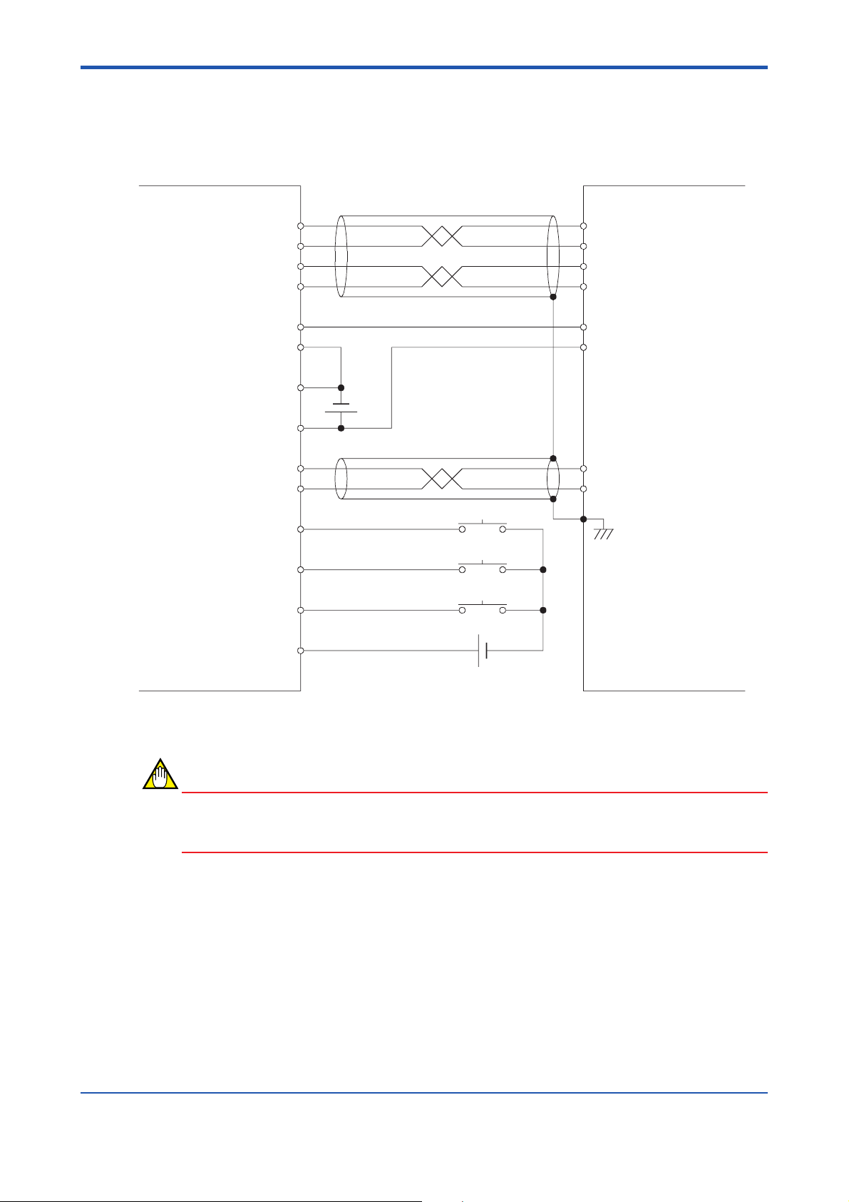
10.2 Example of Connection to YASKAWA Electric
∑II-Series Driver
10-3
Positioning module
Clockwise Pulse –
Clockwise Pulse +
Counterclockwise Pulse –
Counterclockwise Pulse +
Deviation Pulse Clear
Deviation Clear (GND)
External Power Supply 5Vin (GND)
External Power Supply 5Vin
Encoder Z-phase Input –
Encoder Z-phase Input +
Origin Input
Positive-direction Limit Input
Negative-direction Limit Input
13a
14a
11a
12a
10a
9a
8a
8b
18a
15a
4a
3a
2a
5 V DC
Origin Switch
Positive-direction Limit Switch
Negative-direction Limit Switch
YASKAWA Electric Servo Pack SGDN
7
CW Pulse
8
11
12
14
15
20
19
CW Pulse
CCW Pulse
CCW Pulse
CLR
CLR
PCO
PCO
FG
*
*
*
*
Contact Input Common
1a
24 V DC
Figure 10.2 Example of Connection to YASKAWA Electric ∑II Series Driver
CAUTION
Be very sure to check the polarity of the external power supply (5 V DC). If connected with
the wrong polarity, the internal circuitry might be damaged.
F1003.EPS
IM 34M6H55-01E 3rd Edition : Apr 1, 2002-00
Page 83

10.3 Example of Connection to Sanyo Denki PZ
Series Driver
10-4
Positioning module
Clockwise Pulse –
Clockwise Pulse +
Counterclockwise Pulse –
Counterclockwise Pulse +
Encoder Z-phase Input –
Encoder Z-phase Input +
External Power Supply 5Vin (GND)
External Power Supply 5Vin
Deviation Pulse Clear
Deviation Clear (GND)
Origin Input
Positive-direction Limit Input
Negative-direction Limit Input
13a
14a
11a
12a
16a
15a
8a
8b
10a
9a
4a
3a
2a
5 V DC
Origin Switch
Positive-direction Limit Switch
Negative-direction Limit Switch
Sanyo Denki PZ Series Driver
27
Clockwise Pulse +
26
Clockwise Pulse –
29
Counterclockwise Pulse +
28
Counterclockwise Pulse –
47
SG
48
SG
8
C–
7
C+
12
SG
FG
50
Deviation Clear +
34
Deviation Clear –
Contact Input Common
1a
24 V DC
F1004.EPS
Figure 10.3 Example of Connection to Sanyo Denki PZ Series Driver
CAUTION
Be very sure to check the polarity of the external power supply (5 V DC). If connected with
the wrong polarity, the internal circuitry might be damaged.
IM 34M6H55-01E 3rd Edition : Apr 1, 2002-00
Page 84

Revision Information
Document Name : Positioning Modules (with Multi-channel Pulse Output)
Document No. : IM 34M6H55-01E
Edition Date Revised Item
1st Feb, 1999 New publication
2nd July, 2001 Addition of explanations on support of CE Marking; Correction of typographical errors
3rd Apr, 2002 Cover, Appricable product, correction of typographical errors
i
Written by Product Marketing Department, IT Controller Center
Yokogawa Electric Corporation
Published by Yokogawa Electric Corporation
2-9-32 Nakacho, Musashino-shi, Tokyo 180-8750, JAPAN
Printed by Yokogawa Graphic Arts Co., Ltd.
IM 34M6H55-01E 3rd Edition : Apr 1, 2002-00
Page 85

Blank Page
 Loading...