

Page 1
99 Washington Street
Melrose, MA 02176
Phone 781-665-1400
Toll Free 1-800-517-8431
Visit us at www.TestEquipmentDepot.com
1
Page 2

Table of Contents
Specifications…………………………………………………………………………………3
General Safety Instructions .........................................................................................4-5
Component Diagram ...................................................................................................6
App Installation and Tablet Display Overview..............................................................7
Connecting Android to RMS Machine……………………………………………………..8-9
Perform Service............................................................................................................10
Vacuum and Charge ..........................................................................................10
Recover .............................................................................................................11
Full Cycle ......................................................................... .................................12
Performance Check ............................................................................ …………13
Vacuum and Leak Check ...................................................................................18
Job Reports…………………………………………………………………………………...19
2
Machine Maintenance………………………………………………..………………………19
Hose Flush .................................................................................................................. 20
Purging Non-Condensable Gases ...............................................................................20
System Calibrations .....................................................................................................21-22
Filter Change………………………………………………………………………………….22
Tank Refill ....................................................................................................................23
System Setup…………………………………………………………………………………23
Machine List…………………………………………………………………………………..24
Preferences…………………………………………………………………………………...25
Use of Sealant Filter……………………………………………………………….………...25
Change Weight Units……………………………………………..……………….………...25
Auto Connect to Last Machine……………………………………………………...…….. 25
Maintenance Procedures……………………………………………………………………26-29
Changeover Procedure ...............................................................................................29-30
Troubleshooting Information.........................................................................................31-34
Repair Parts List ..........................................................................................................35
Limited Warranty for 37840 & 37860 ...........................................................................36
Page 3

WARNING! CAUTION!
Before operating this unit, please read this manual thoroughly. You must understand the procedures
outlined in this manual. Failure to follow these procedures could void all warranties.
Before handling refrigerants, read the material safety data sheet (MSDS) from the refrigerant
manufacturer.
Inhalation of high concentration of refrigerant vapors is harmful and may cause heart irregularities,
unconsciousness, or death. Deliberate inhalation of refrigerants is extremely dangerous. Death can
occur without warning. Vapors reduce oxygen available for breathing and are heavier than air.
Decomposition products are hazardous. Liquid contact can cause frostbite. All refrigerant containers,
equipment, and hoses are under pressure.
3
37840, 37860 Refrigerant Management System
Specifications
Refrigerants: 37840 – Factory set for R-134a
37860 – R-1234yf
Electrical:
Compressor: Single 1/2 HP Hermetic Compressor
Power Source: 120V AC 60Hz for US Models
Amperage: 10 amps
Auxiliary Outlets: 10 amps maximum
2 amps during recovery
Size:
Height: 45 inches
Width: 22 inches
Depth: 29 inches
Weight: Maximum 265 lb. with full tank
Pressure:
Low side: Factory tested 186 psig
High side: Factory tested 350 psig
Page 4

4
General Safety Instructions
Know your equipment. Read and understand the
operation manual and labels affixed to the unit.
Learn its application and limitations as well as the
specific potential hazards of your equipment.
ALWAYS WEAR SAFETY GOGGLES.
Ground all equipment. This unit is equipped with
an approved 3 prong grounding-type plug. The
green ground wire should never be connected to a
live terminal.
Use the Proper Extension Cords. Use the
following guide for choosing the proper extension
cord and keep such cords at a minimal length.16
Ga. Minimum.
Cord Gauge – Maximum Length
16 Ga. - 25 feet
14 Ga. - 50 feet
12 Ga. - 100 feet
Avoid Dangerous Environments. Do not use this
unit in damp locations or expose it to rain. This
equipment should be used in a location with
mechanical ventilation that provides at least four air
changes per hour. This equipment should not be
used near open containers of flammable liquids.
Disconnect Unit from Power Supply Before
Servicing. An electrical shock hazard is present
when the unit is disassembled or the cowling is
removed.
Repair Damaged Parts. Do not operate the unit
with a defective part. Have unit repaired to proper
operating conditions. Only use factory authorized
parts. Any service to the machine not outlined in
this manual should only be done by factory
authorized service personnel. Ritchie Engineering
is not responsible for any lost refrigerant.
Use Recommended Accessories. Follow the
instructions that accompany all accessories.
Improper use of accessories may damage
equipment or create a hazard.
Use Caution When Connecting or
Disconnecting. Improper usage may result in
refrigerant burns (frostbite). If a major refrigerant
leak occurs, proceed immediately to a well
ventilated area. The hoses included with this unit
are supplied with couplers that, when closed,
prevent refrigerant vapors from venting when
disconnecting from the automobile.
Only Use the 37840 and 37860 with the Correct
Refrigerants. The 37840 and 37860 approved for
use only with R-134a and R-1234yf. Take care to
only use the refrigerant for which the machine is
currently configured.
CAUTION! The 37840 and 37860 are designed to
handle multiple refrigerants but not concurrently.
Only service systems containing the refrigerant for
which the machine is currently configured to run.
Operate the Unit within the Design
Environment. The 37840 and 37860 are designed
to operate in a temperature range from 40°F to
120°F. The unit should also not be operated in a
wet location.
WARNING! Refrigerant, in liquid and vapor form,
is a potentially hazardous material. Please consult
the manufacturer’s Material Safety Data Sheet for
additional information and adhere to the following
safety guidelines:
Avoid breathing high concentrations of
vapors.
Use with sufficient ventilation to keep
operator exposure below recommended
limits, especially in enclosed and low lying
areas.
Avoid contact of liquid refrigerant with the
eyes and prolonged skin exposure.
Wear goggles and protective gloves.
Do not attempt to operate this unit above
120°F ambient temperature.
Do not allow refrigerants to contact open
flame. Refrigerant decomposition in a flame
results in phosgene gas. Breathing
phosgene gas can be fatal.
Page 5

FIRST AID: If high concentrations of refrigerant
are inhaled, immediately remove the victim to
fresh air. Call a physician or emergency medical
technician. Keep calm. If not breathing, give
artificial respiration. If breathing is difficult, give
oxygen. Do not give epinephrine or similar drugs.
EYE: In case of liquid contact, immediately
flush eyes with plenty of water. Call a
physician.
SKIN: Flush with water and if necessary, treat
for frostbite gently warming affected area.
CAUTION! All refrigerant hoses, recovery tanks,
refrigerant lines, and other vessels containing
refrigerants should be handled as if under high
pressure.
CAUTION! Improper use or handling of equipment
could lead to damage increasing the risk potential
of leaks. Always use care when transporting
equipment and when servicing components to
avoid damaging refrigerant tubing.
CAUTION! This machine should only be operated
by certified personnel.
5
CAUTION! Avoid breathing A/C refrigerant and
lubricant vapor or mist. Exposure may irritate eyes,
nose, and throat. To remove refrigerant from the
A/C system, use only equipment certified for the
type of refrigerant being removed. Additional
health and safety information may be obtained
from refrigerant and lubricant manufacturers.
CAUTION! Do not pressure test or leak test
equipment and/or vehicle air conditioning systems
with compressed air. Some mixtures of air and
refrigerant have been shown to be combustible at
elevated pressures. These mixtures, if ignited,
may cause injury or property damage. Additional
health and safety information may be obtained
from refrigerant and lubricant manufacturers.
WARNING! R-1234yf is classified as an A2L
flammable refrigerant. Caution should be taken
when working with this refrigerant. See
refrigerant manufacturers SDS for more
information.
Page 6
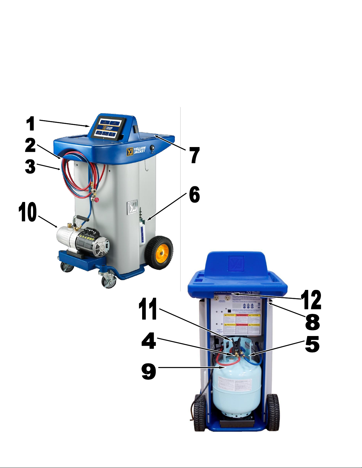
1.
Tablet (Control Panel)
7. Tool Trays
2.
Auto High Side Hose (Red)
8. Main Power Switch
3.
Auto Low Side Hose (Blue)
9. Refrigerant Storage Tank
4.
Tank Vapor Hose (Red)
10. Vacuum Pump
5.
Tank Liquid Hose (Blue)
11. Tank Temperature Clamp
6.
Oil Drain Bottle
12. Auxiliary outlets
Component Diagram
6
Page 7
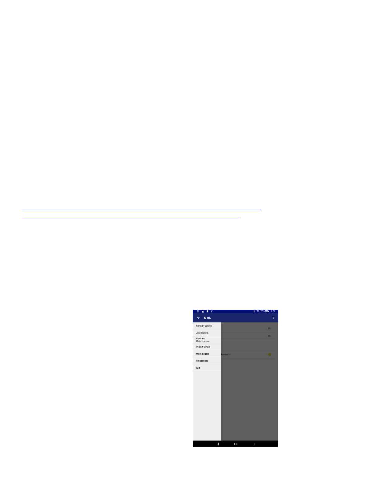
App Menu
To access the main app menu, click the menu icon in
the upper left corner of the app.
App Install and Configuration
Periodic updates to the App for running the machine are released for improved user information and for
optimized system performance. Before operating the machine it is recommended to contact Ritchie
Engineering to guarantee that the latest software version is installed. If the software is current proceed with
setup otherwise tech support will assist in updating the software.
Note: For tech support to assist in updating the tablet software the tablet needs to be connected on a
local Wifi connection. The machine does not need to be present to update the tablet software.
Note: All versions of released software will allow the user to accurately and safely perform service.
Updates to the software are made, for example, to improve user workflow within the software.
Note: App updates will be pushed to both the Google Play Store, and the Amazon App Store. Your
device will update itself automatically.
https://play.google.com/store/apps/details?id=com.yellowjacket.android&hl=en
https://www.amazon.com/Ritchie-Engineering-Inc-RMS/dp/B078XJ8NNV
7
Tablet Display Overview
Tablet display provides the unit operator with continual updates of the status of the machine while allowing the
operator to move away from the machine. In addition, the display will prompt the technician for the user input
needed to continue operation. The display also shows error codes for rapid diagnosis of abnormal conditions.
38
Page 8
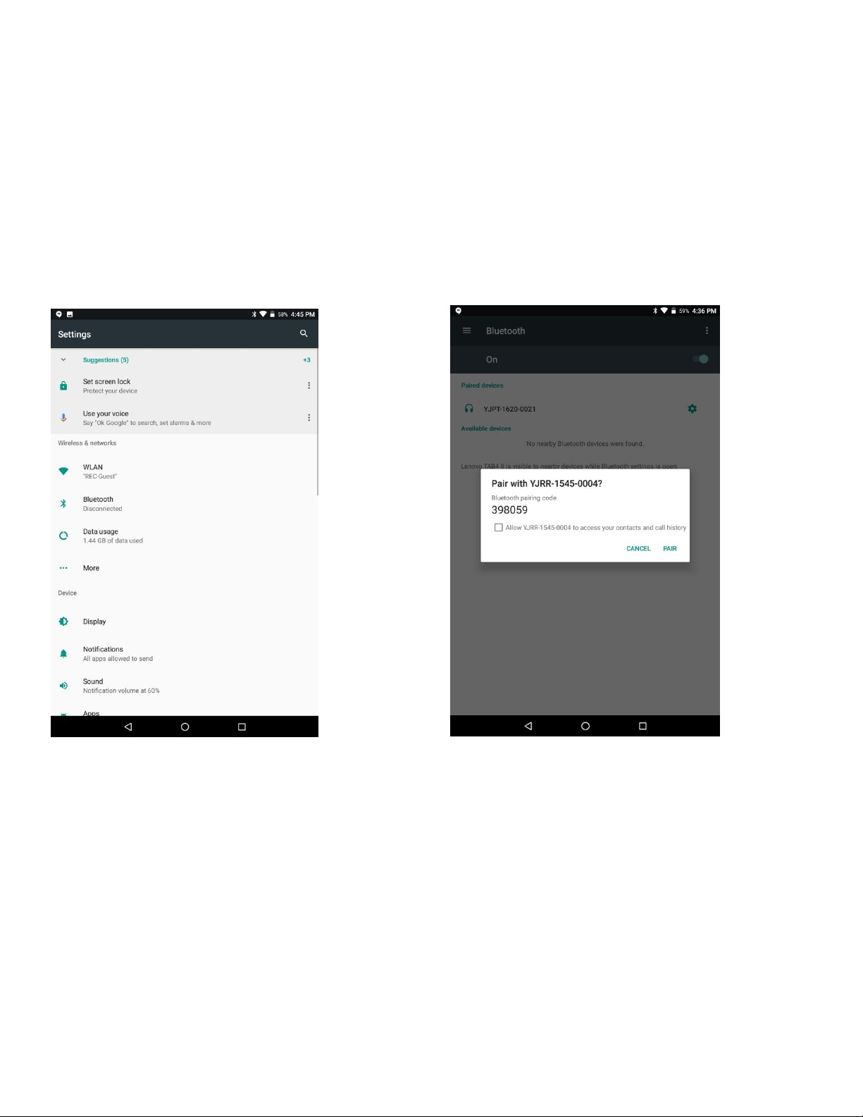
CONNECTING ANDROID TO RMS MACHINE
Tablet settings> Wireless> Tap on Bluetooth-Turn on if not already on
Turn on RMS machine> Tap on Available devices>Pair Bluetooth device-Choose
(Prefix YJRR)
Exit Wireless settings
8
38
Page 9
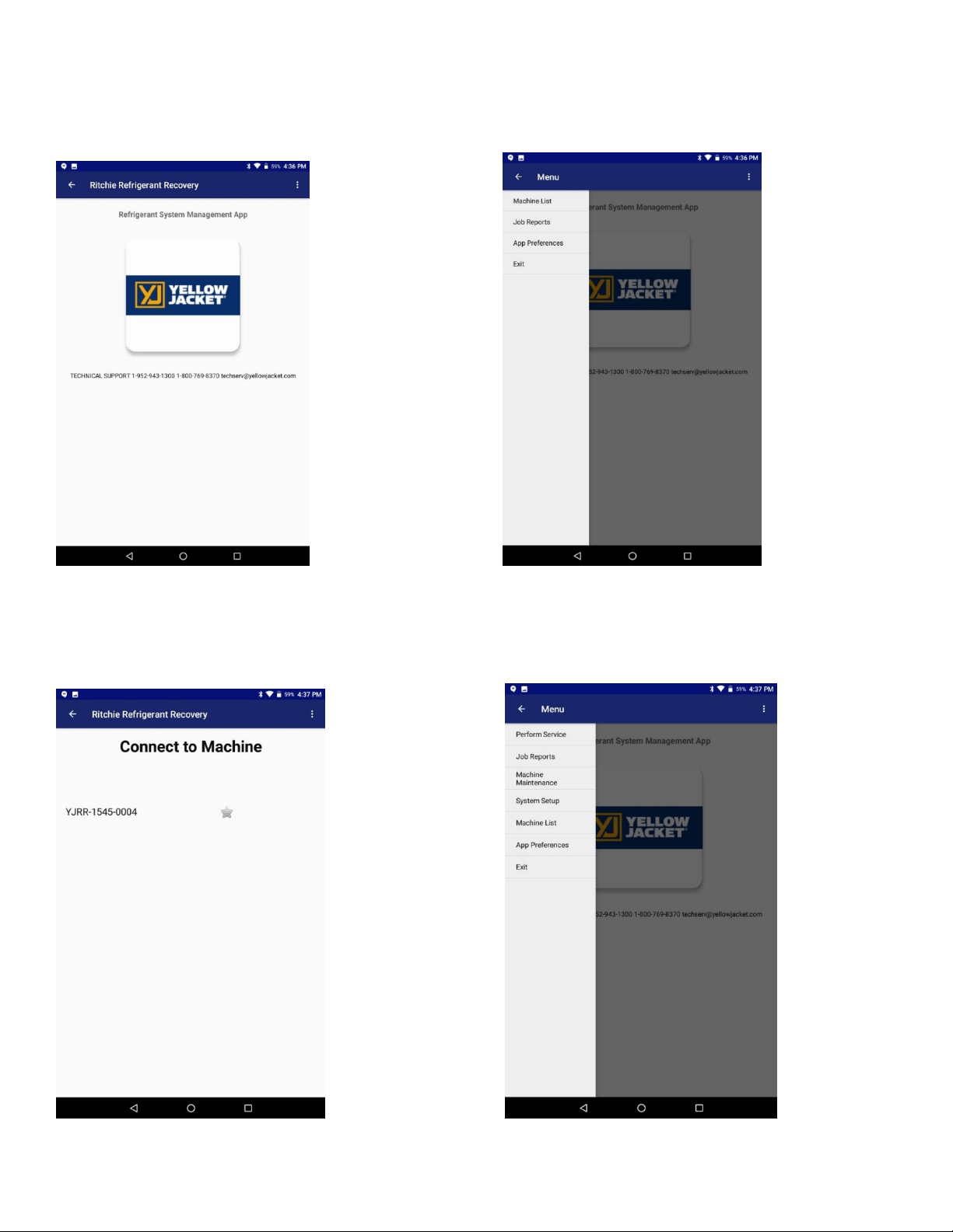
Open the RMS app>Click on the arrow in the upper left corner>Machine list
9
Select your RMS machine (Prefix YJJR)>Tap on the name. Choose your function.
38
Page 10
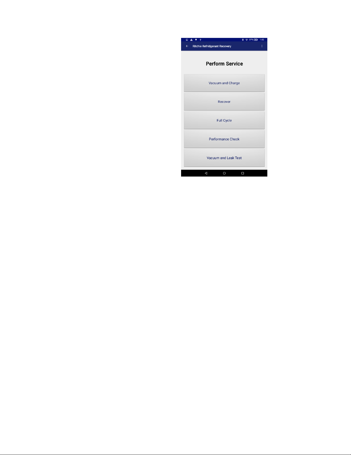
10
Perform Service
The Perform Service screen has all the options you
will need to provide service on a vehicle after the
diagnostic has been completed.
Vacuum and Charge
Vacuum and Charge Operational Steps:
1. Verify that the vehicle and its air conditioning system are off.
Note: Before attempting any charging operation go to SYSTEM SETUP to see how much Chargeable
Weight of refrigerant is available. Must be a minimum of 10 lbs.
2. From the Main Menu select PERFORM SERVICE.
3. If desired enter a unique job name. This name will be tied to this job can help you keep track of AC jobs on
specific vehicles.
4. Fill out the job form as it pertains to the vehicle being serviced and hit NEXT.
Note: The minimum vacuum time is 5 minutes and a 10 - 15 minute minimum vacuum time is
recommended to ensure full evacuation of the system and accurate charging for normal sized
systems.
Note: Due to SAE regulations the charge amount must be displayed to the user in KILOGRAMS, so we
provide a real-time conversion (read-only) showing the charge amount, if your preferences are set to
Lbs.
For hybrid vehicles it may be necessary to perform a hose flush. If necessary perform a hose flush.
7. The display should read “CONNECT SERVICE HOSES TO THE VEHICLE. PRESS START TO BEGIN.”
38
Page 11

8. Connect the high and low side auto service hoses to the respective high and low side service ports on the
automobile A/C system.
9. Open the service hose valves by tightening the knob on the top of the service hose coupler and push
START.
10. The machine will now go through the vacuum and leak test procedure required before charging per SAE
J2843 as outlined in the Vacuum and Leak Check section.
11. After the vacuum and vacuum hold time the display will read “STABILIZING PLEASE WAIT” The unit will
then automatically start the charge cycle. The display will show the charging process progress. The unit will
beep when the desired charge amount has been transferred to the A/C system.
NOTE: The last 3 oz. of refrigerant charge will be metered in by the charging solenoid. It is normal to
hear a clicking sound while charging.
12. Verify the message on the display reads “CHARGE COMPLETE.”
13. Close the service valves and disconnect the high and low side auto service hoses from the automobile.
14. After disconnecting the service hoses from the vehicle press the RESET key and allow the machine to
complete its automatic hose clearing procedure.
15. If any lubricant was pulled out of the system during service replace it with the same amount of only new
lubricant using an oil injector such as the YELLOWJACKET 37842.
11
Recover
The Recovery Option should be used to fully recover and recycle all refrigerant from an air conditioning
system. For instance, if the system needs to be opened to atmosphere to replace a part, all refrigerant must be
removed before opening the system.
RECOVER Operational Steps
1. Verify that the vehicle and its air conditioning system are off.
2. From the main menu select PERFORM SERVICE.
3. Fill out the job form as it pertains to the vehicle being serviced and hit NEXT.
4. The live display box should read “CONNECT SERVICE HOSES TO VEHICLE ENTER TO CONTINUE.”
5. Connect the high and low side auto service hoses to the respective high and low side service ports on the
automobile A/C system.
6. Open the service hose valves by tightening the knob on the top of the service hose coupler.
7. Press START to begin recovery operations.
38
Page 12

12
WARNING
DO NOT RECOVER CONTAMINATED REFRIGERANT WITH THIS UNIT. RECOVERING CONTAMINATED
REFRIGERANT WILL VOID ALL WARRANTIES AND MAY CAUSE DAMAGE TO OTHER AUTOMOBILES
SERVICED IN THE FUTURE.
8. During the recovery operation, refrigerant is removed from both the high and low side of the automobile air
conditioning system. The tablet will display the amount of refrigerant currently recovered during the cycle and
the status window will read “RECOVERING REFRIGERANT
Full Cycle
The Full Cycle function is designed to remove, clean, and recharge all refrigerant in an A/C system by
transferring the refrigerant to the storage tank, filtering out contaminants, removing any moisture in the system
by pulling a vacuum, and charging the system backup with a precise amount of refrigerant.
Operational Steps
1. Verify that the vehicle and its air conditioning system are off.
Note: Before attempting any charging operation go to SYSTEM SETUP to see how much Chargeable
Weight of refrigerant is available. Must be a minimum of 10 lbs.
2. From the Main Menu select PERFORM SERVICE
3. Select FULL CYCLE.
4. Fill out the job form as it pertains to the vehicle being serviced and hit NEXT.
Note: Due to SAE regulations the charge amount can only be entered in grams/kilograms. However
there is a real-time Lbs. conversion box on the screen, if your settings are set to Lbs.
Note: The minimum vacuum time is 5 minutes and a 10 - 15 minute minimum vacuum time is
recommended to ensure full evacuation of the system and accurate charging for normal sized
systems.
Note: On the 37840 machine configured for R-134a the Vacuum Hold Time can be bypassed if the time
is set to zero.
5. The display should read “CONNECT SERVICE HOSES TO VEHICLE”.
6. Connect the hoses to the vehicle and press START to begin full cycle operations.
7. The unit will begin to recover as outlined in the Recover Only cycle. Once the refrigerant has been
recovered, the machine will automatically begin evacuating the system with the same procedure as Vacuum
and Leak Check and will beep to indicate the end of the Vacuum Time and after the Vacuum Hold if Vacuum
Hold is used.
38
Page 13

13
8. After the Vacuum and Vacuum Hold Time the display will read “STABILIZING PLEASE WAIT” The machine
will then start the charge cycle.
9. The display will show the charging process progress. The unit will beep when the desired charge amount
has been transferred to the A/C system.
NOTE: The last 3 oz. of refrigerant charge will be metered in by the charging solenoid. It is normal to
hear a clicking sound while charging.
10. Verify the message on the display reads “CHARGE COMPLETE.”
11. Close the service valves and disconnect the high and low side auto service hoses from the automobile.
12. After disconnecting the service hoses from the vehicle press the RESET key and allow the machine to
complete its automatic hose clearing procedure.
13. If any lubricant was pulled out of the system during service replace it with the same amount of only new
lubricant using an oil injector such as the YELLOWJACKET 37842 for R-134a or 37862 for 1234yf.
Performance Check
To check the performance of the vehicle’s AC system before or after servicing the system use the included
ManTooth pressure gauges and the performance check to get an accurate reading of the vehicle’s running
pressures. Using the included ManTooth gauges to measure system pressures helps to ensure that the most
accurate charge possible is going into each vehicle as well as minimizing refrigerant loss and reducing
unnecessary recoveries.
System Performance Check Steps
1. Do not turn the vehicle on until ready. Before turning the vehicle’s air conditioning system on verify that the
ManTooth is securely connected to the vehicle and that the Recovery Machine is not connected to the to the
system.
2. From the main menu select PERFORM SERVICE.
3. Select PERFORMANCE CHECK.
4. If the ManTooth App has already been installed, it should launch. If not, it will bring you to the Google Play
store location where it can be installed.
5. Ensure that the ManTooth is turned on and connect with it. This demonstrates how to set up your Mantooth
connection:
38
Page 14
14
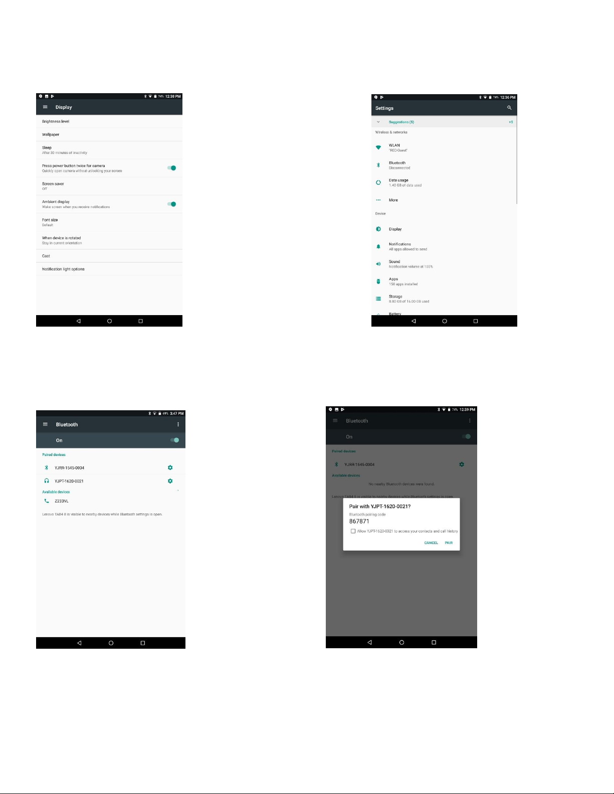
Tablet settings (GEAR)>Display>Find when device is rotated- Choose “Stay in current
orientation”>Set Sleep to 30 minutes> Tap on arrow Back soft key on bottom tool bar
Tablet Settings> Wireless>Tap on Bluetooth-Turn on if not already on
Turn on Mantooth-Tap on Available devices> >Pair Bluetooth Device-Choose Mantooth(Prefix YJPT)
> Exit Wireless Settings(Tap on bottom soft key circle)
38
Page 15
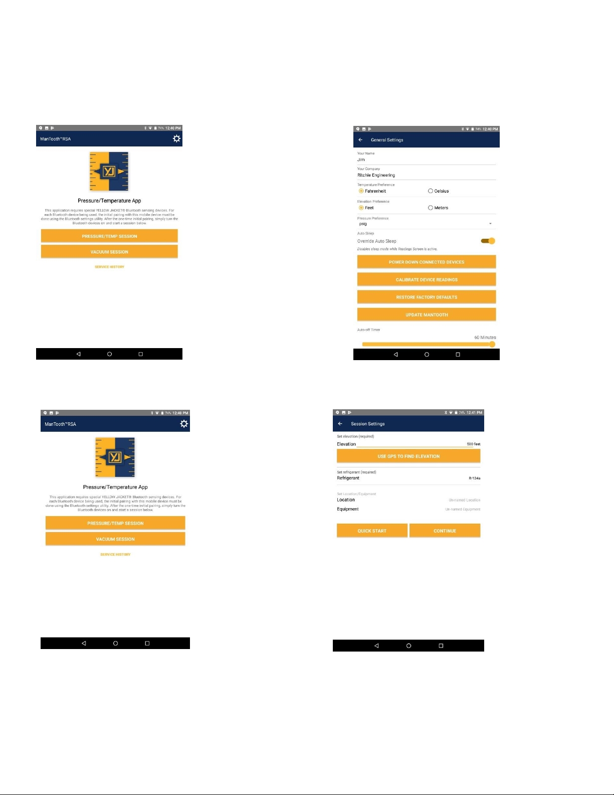
Open ManTooth App> Go to Settings (upper right corner GEAR) Choose temperature and elevation
preferences> Turn Override Auto Sleep ON> Or Adjust Auto off Timer scale to 60 minutes (On the
bottom of the page) Exit (Tap on arrow in upper left)
15
Choose Pressure/Temp session Select Elevation & Type of Refrigerant
Tap on Continue
38
Page 16
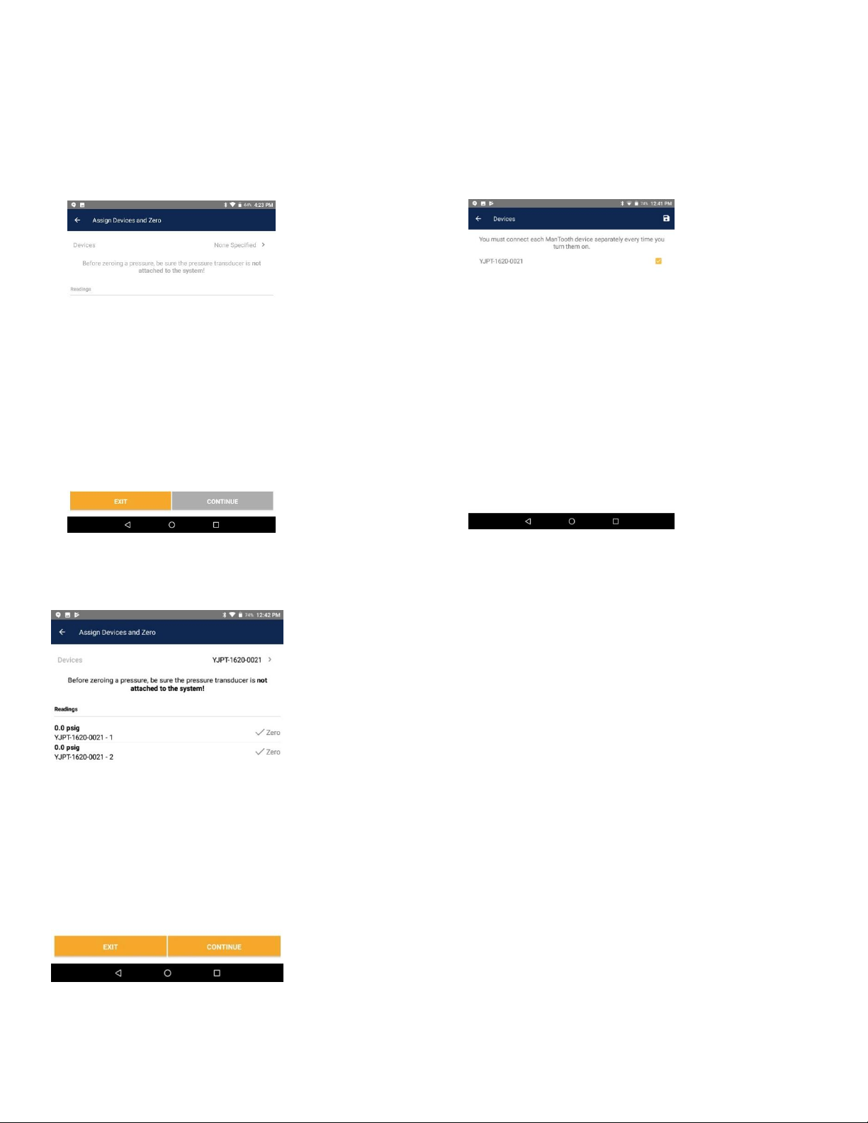
Devices-Tap on none specified> Tap on box next to appropriate Mantooth serial # (Make sure
Mantooth blue light is on)> Tap save (Upper Right Corner) The blinking blue light will turn solid blue
when connected.
16
Make sure pressure readings are 0 (If not release pressure in AC couplers)
Zero ManTooth 1 & then ManTooth 2 by tapping on the word zero one at a time>Continue
38
Page 17
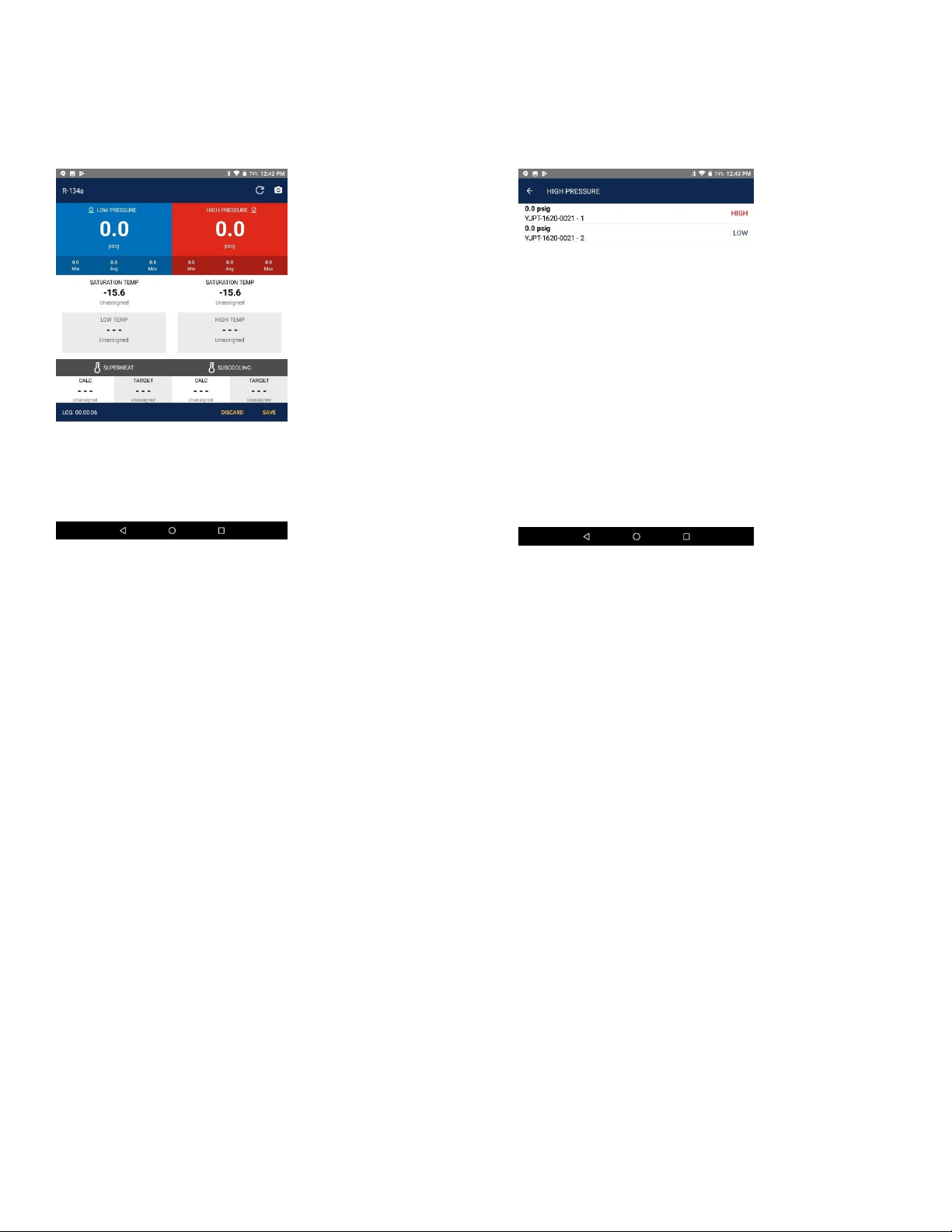
Tap on high pressure gauge>Tap on whichever module you assigned to HIGH- Tap on low pressure
gauge> Tap on the other module and assign LOW (1 is the PT Module-2 is the PT Tether)
17
Tapping on the circle on the bottom tool bar will hide the ManTooth App. Tapping on the square will
show your open sessions.
6. Once the app has connected to the ManTooth recall the high and low side gauges.
7. Turn on the vehicle’s AC system to read the running pressures on the tablet screen. The needles on the
gauges will point to the correct pressures and the digital readout will provide a more accurate pressure
reading.
8. After analyzing the running pressures hit the Exit Application button to close the gauges and return to the
main app.
Alternate Startup
Another way to start the Performance Check is to directly start the ManTooth app directly. Starting the
Performance Check this way enables the user to check the running pressures of a vehicle without having to
bring the entire Recovery Machine over to the vehicle. This will require reconnecting to the ManTooth once the
RMS app is launched.
38
Page 18

18
Vacuum and Leak Check
The vacuum function of this machine is designed to remove air/moisture from the automobile A/C system by
pulling a deep vacuum. This mode is most often used after completing a repair that required opening the A/C
system to the atmosphere. Moisture in an A/C system can cause erratic operation and/or damage and must be
removed before recharging the system with refrigerant.
VACUUM Operational Steps
1. Verify that the vehicle and its air conditioning system are off.
2. From the main menu select PERFORM SERVICE
3. Select VACUUM AND LEAK TEST.
4. Fill out the job form as it pertains to the vehicle being serviced and hit SUBMIT.
Note: The default minimum vacuum time is 5 minutes and a 10 - 15 minute minimum vacuum time is
recommended to ensure full evacuation of the system and accurate charging for normal size vehicles.
Note: On the 37840 machine configured for R-134a the Vacuum Hold Time can be bypassed if the time
is set to zero.
5. The display will read “CONNECT SERVICE HOSES TO THE VEHICLE. PRESS START TO BEGIN”.
6. Connect the high and low side auto service hoses to the respective high and low side service ports on the
automobile A/C system.
7. Open the service hose valves by tightening the knob on the top of the service hose coupler.
8. Press the START key to begin the vacuum operation.
Note: If the automobile A/C system has pressure in it, the unit will automatically begin a recovery cycle
to ensure that no refrigerant is released into the atmosphere.
9. The machine will begin to evacuate the A/C system and will beep to indicate the end of the vacuum time.
10. Following the Vacuum Time the unit will begin the vacuum hold automatically. The current vacuum level
and the vacuum level at the start of vacuum hold will be shown on the display. The hold time will count down
on the display and the unit will beep at the end of the hold time.
11. Note the final vacuum level shown on the display and the starting vacuum level. If the two recorded
vacuum levels are different, the A/C system may have a leak and might not retain refrigerant when charged.
12. Verify the message on the display reads “VACUUM COMPLETE.”
13. Close the service valves and disconnect the high and low side auto service hoses from the automobile.
38
Page 19
19
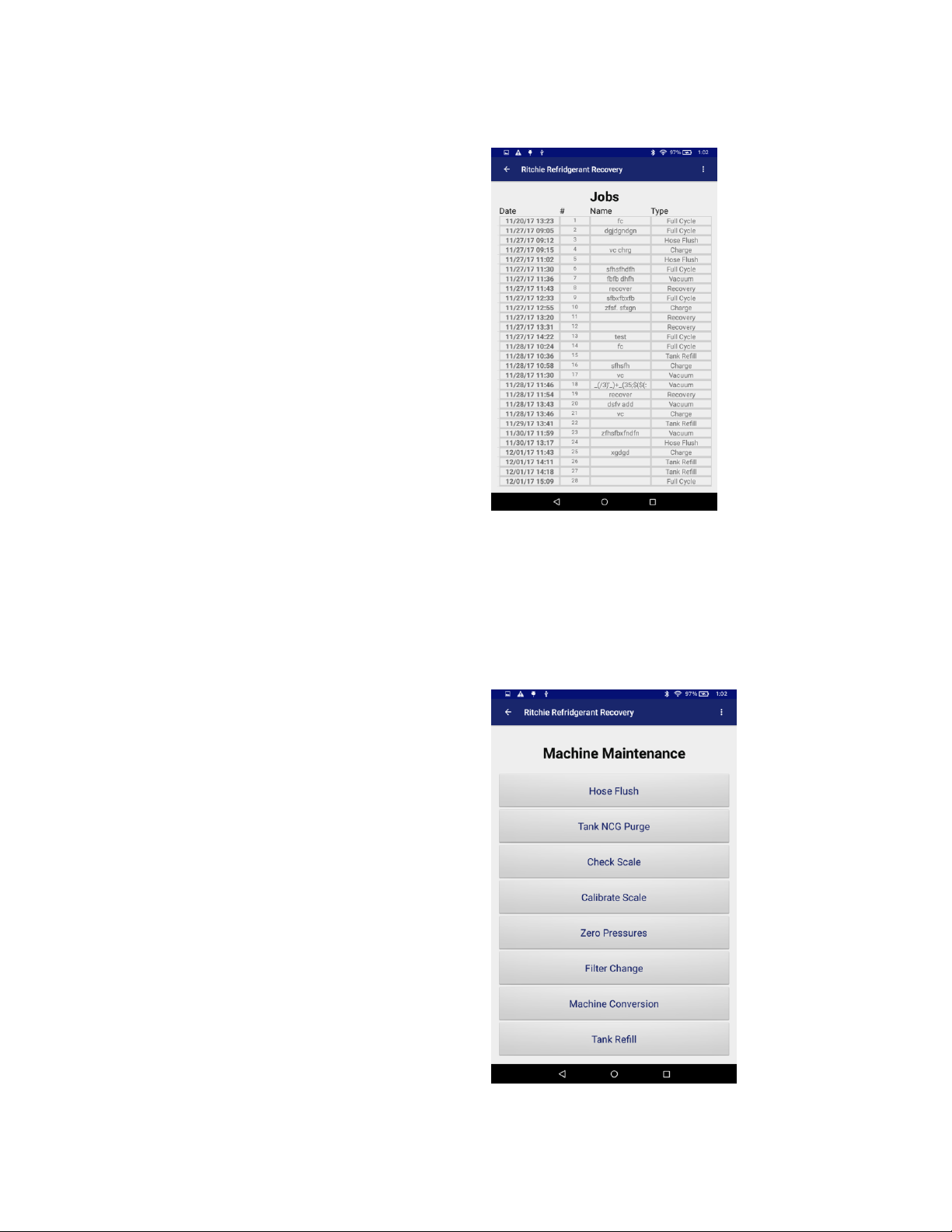
Job Reports
Choose this option to view service history. Here you
can view previous jobs to show customer history or
e-mail the information.
Machine Maintenance
Here you will be able to check the scale calibration,
re - zero the pressure transducers, and find the
procedure to change the filter drier. Additionally, if
your machine is a 37840 this is the location to begin
the one-time changeover procedure to change the
configuration of the machine from R-134a to R1234yf.
38
Page 20

20
Hose Flush
The Hybrid Hose Flush feature is used to remove residual oil and contaminates from the unit and hoses. The
SAE J2788 standard for R-134a require that the unit remove the residual oil so there isn't a risk of cross
contaminating the oil in a hybrid A/C system. Failure to perform this function before working on a hybrid A /C
system can cause serious issues with the electrical system. Having too much of the wrong type of oil in a
hybrid A/C system can cause damage to the compressor as well as conduct the electricity to the outside of the
A/C compressor creating the risk of shock.
SERVICING HIGH VOLTAGE A/C SYSTEMS.
Due to issues with oil contamination in High Voltage A/C systems, the 37840 have a unique flushing feature
that reduces cross contamination of oil to a level below specifications set by SAE and OEMs.
It is therefore necessary to perform the following procedure before working on a High Voltage A/ C system.
1. After submitting a job name select HOSE FLUSH.
2. When the display reads “PLEASE CONNECT FLUSH ADAPTER ” connect the supplied flush adapter
between the high and low side hoses. ((Replacement part numbers 38132 for R-134a, 19245 FOR 1234yf)
3. Press the ENTER key to begin the process.
4. The display will then read “FLUSHING HOSES PLEASE WAIT”.
5. When the process is complete press the BACK key to return to the main menu to continue with the vehicle
service.
Purging Non-Condensable Gases
The 37840 is designed to automatically purge Non-Condensable Gases (NCGs) such as air present in the
storage tank. The machine uses an algorithm based on the temperature and pressure of the tank and the
refrigerant inside to determine if there are NCGs present. When it is determined that there are NCGs in the
onboard tank, the unit will purge the excess NCGs.
The unit will automatically check for NCGs at the beginning of any job cycle that includes charging of
refrigerant into a vehicle, such as a full cycle. You can also have the machine check for NCGs at other times.
To manually check for and purge NCGs, from the home screen go into Machine Maintenance and select TANK
NCG PURGE. This will tell the machine to check for NCGs, perform a purge if necessary, and then clear the
system.
The maximum purge time is set to 15 seconds to minimize potential refrigerant loss. If you suspect that a purge
cycle was insufficient to remove all NCGs from the recovery tank you can repeat the purge cycle by pressing
the TANK NCG PURGE button again. If after multiple purge cycles the machine continues to purge, there may
be an error in the system. Check the pressure in the tank to determine if the system is purging unnecessarily.
38
Page 21

21
Check Scale
NOTE: Before doing any Scale calibration procedure, check this first:
1. Remove tank from machine scale. You may have to take both tank hoses off. Close the tank valves first.
2. In the MAIN SCREEN tap on SYSTEM SETUP.
3. With no weight on the scale read the scale ADC line:
4. This reading should be under 10,000. The best numbers should be 3000-8000. If close to 10,000 or
above the scale will need to be replaced. If ADC reading is good proceed to either CHECK SCALE or
CALIBRATE SCALE.
The Check Scale process will start by asking the user to place a small weight on the scale to verify whether the
scale is reading accurately. The user is then given a choice to proceed on to Scale Calibration if they are
unsatisfied with the scale accuracy.
Scale Calibration Check
1. With the tank still connected and on the scale s elect MACHINE MAINTENANCE in the main menu.
2. Select CHECK SCALE.
3. Press the “START” key to stabilize.
4. After stabilizing, machine will display “PLACE THE TEST WEIGHT ON THE TANK” (calibration check
weight supplied).
5. Press the “START” key.
6. Check to see if the displayed weight and value of the test weight are within 0.005Kg.
7. If out of calibration follow the steps displayed on the display to calibrate the scale.
Example:
Test weight = 500g (0.500 kg)
Machine reading: 0.494 k g = Out of Calibration
Machine reading: 0.500 kg = Good
Machine reading: 0.506 k g = Out of Calibration
Note: 500g = 1.1 lb.
If the scale calibration changes, a message reading “WARNING SCALE CALIBRATION” may appear on the
screen. To reset the warning message follow the on screen instructions or do the following:
1. Select MACHINE MAINTENANCE in the main menu.
2. Select CALIBRATE SCALE.
38
Page 22

22
3. The display will then read “REMOVE TANK FROM SCALE”.
4. Disconnect the hoses and remove the tank from the scale.
5. Once the tank is removed and there is nothing on the scale press the START key.
6. The display will then read “CALIBRATING PLEASE WAIT”.
7. When the display reads ATTENTION! Put the 20lb. weight on the scale and press ENTER-DO NOT PRESS
ENTER UNLESS YOU HAVE A CALIBRATED 20LB. WEIGHT-Press RESET.
8. Carefully place the tank back on the scale and reconnect the hoses, temperature clamp, and ground wire
and turn the main power switch back on.
Zero Pressure Transducers
1. Select MACHINE MAINTENANCE in the main menu.
2. Next select ZERO PRESSURE TRANSDUCERS.
3. Follow the onscreen instructions and install the hose flush adapter into the Low Side (blue) vehicle hose
coupler and open the coupler by turning the knob clockwise and press START.
4. The machine will automatically check the pressure transducers and rezero them if necessary.
Filter Change
NOTE: You MUST have your filter code before continuing.
1. Select FILTER CHANGE from the Machine Maintenance menu.
2. The app will instruct you to power down the machine and perform the physical filter change.
3. Power on the machine when complete, the app should automatically reconnect to the machine. If it does not,
you might need to select the machine from the “Machine List” menu option to connect.
4. Upon reconnecting to the machine, the app will bring you to the FILTER CODE ENTRY screen. Per SAE
requirements, enter the code on the filter to reset the filter memory on the app and machine.
38
Page 23
23
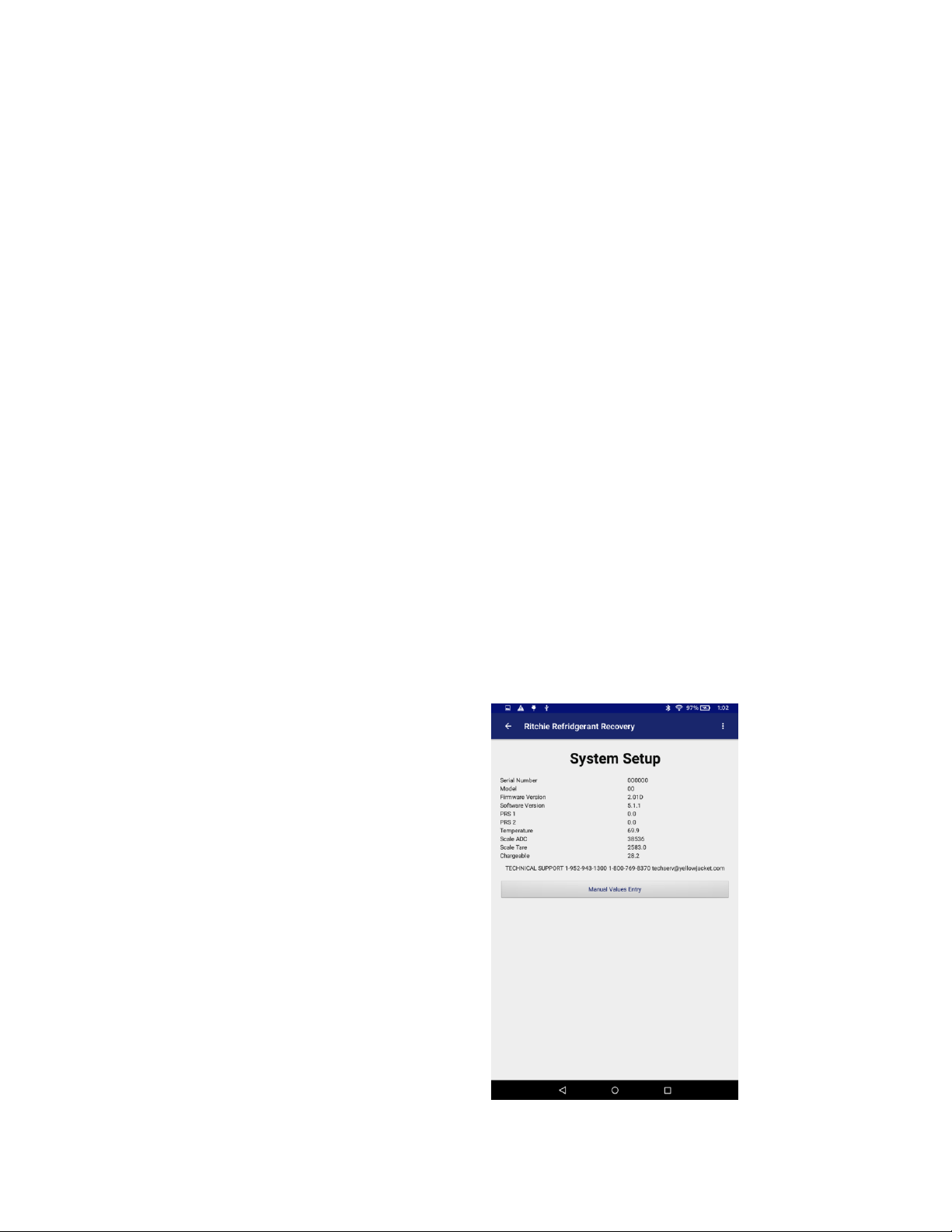
System Setup
This view shows real-time values coming from a
connected machine and also has a keypad to allow
technicians to access real-time administrative
settings.
- Typing 1234 and Enter into the keypad
should bring you to the “administrative”
screen.
- At the administrative screen you can clear or
export the job database.
Tank Refill
In order to use the charging mode, you must have at least ten (10) pounds of refrigerant in the storage tank.
Follow this procedure to add refrigerant to the storage tank. When adding refrigerant to the onboard storage
tank you will need to use the tank refill adapter (Part Number 36211 for R-134a and 19244 for 1234yf) supplied
in the accessory kit. The adapter connects the low side vehicle hose to the tank of new refrigerant. It should be
stored in the tool tray on the top of the unit.
1. Select TANK REFILL from the Machine Maintenance menu.
2. Connect the blue low side auto service hose to the new refrigerant source tank and open the tank valve.
Turn the source tank upside down to enable all of the refrigerant is transferred to the storage tank on the unit.
Press the ENTER button.
3. Press the START button. Refrigerant will transfer to the storage tank. The unit will shut off automatically
when either the supply tank is empty or the storage tank is full.
4. Press the BACK button to return to the main menu.
5. Remember to remove the tank fill adapter from the refrigerant source tank before disposing of the empty
cylinder. Save adapter for future use.
It is recommended that every two months the pressure transducers and the scale be checked for accuracy.
After extended use the 37840 may require the pressure transducers to be re-zeroed and or the scale to be
recalibrated.
38
Page 24
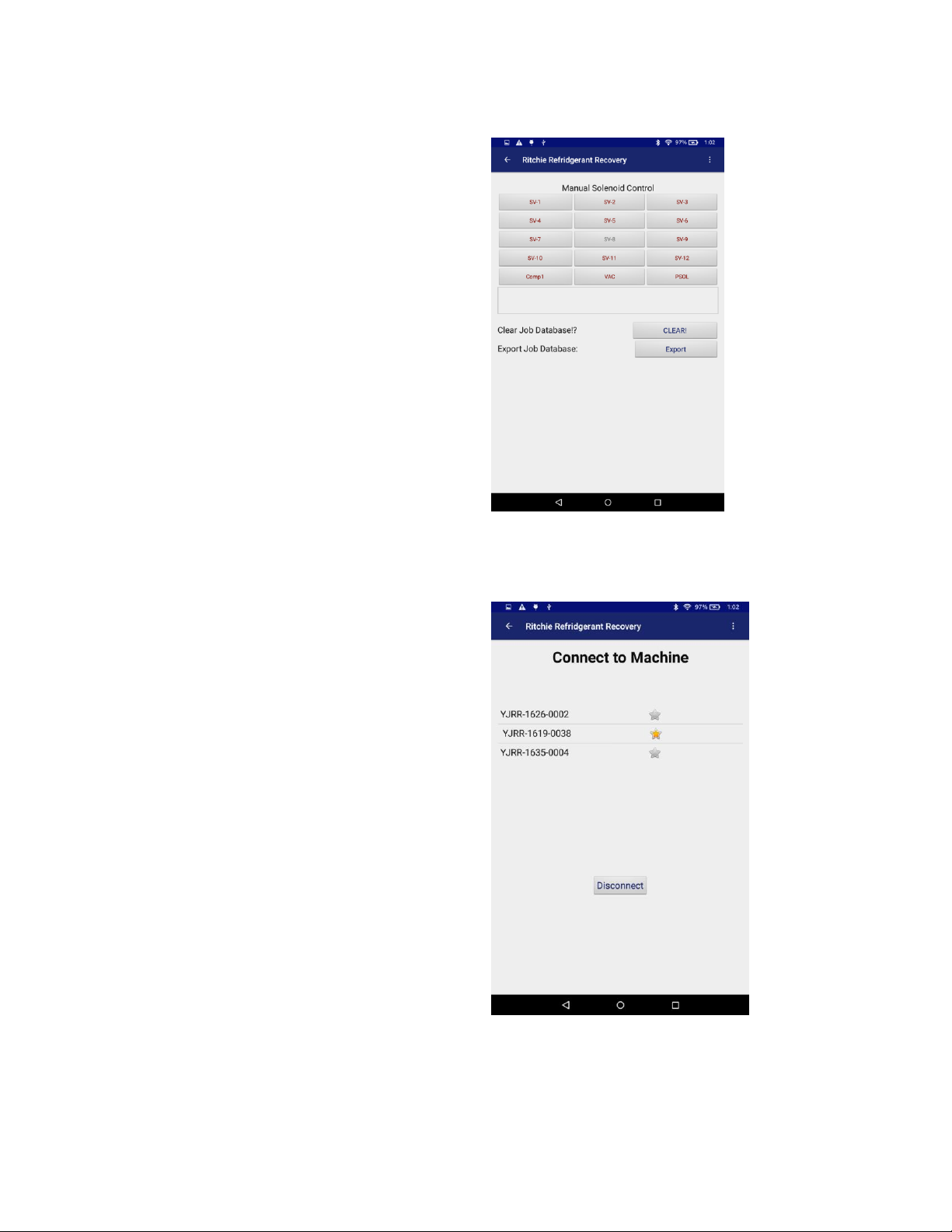
Manual Solenoid Setup
(Admin Screen)
Machine List
This view gives you the option of connecting or
disconnecting to any paired machine.
24
38
Page 25
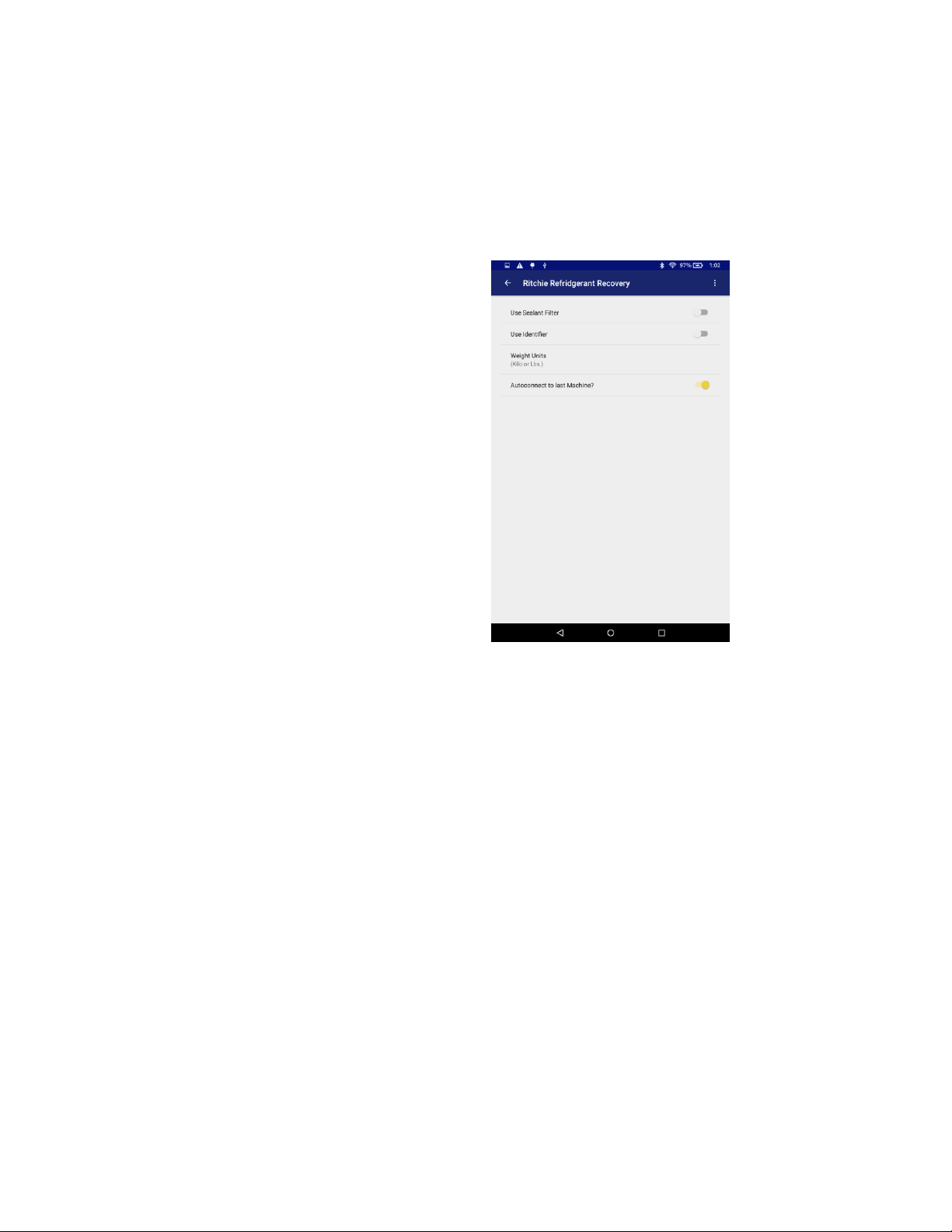
Preferences
Preferences are saved automatically and
immediately.
Exit
Disconnects from a machine if needed and closes out of the app.
25
Use Sealant Filter
The sealant filter is an aftermarket add-on to the R-134a machine. If you have added one, this setting needs to
be turned on so the machine is notified.
Change Weight Units
The user has the option of changing the weight units from KILOGRAMS to POUNDS. Based upon what the
user selects, the weights should display accurately in the selected units, and there should be a label next to the
value stating either Kilos or Lbs. The following screens are affected:
- Live Data
- Job Parameters
- Job Details Report
Auto-Connect to Last Machine
This setting (when turned on) will cause the app to attempt to connect automatically to the last machine it was
connected to.
38
Page 26
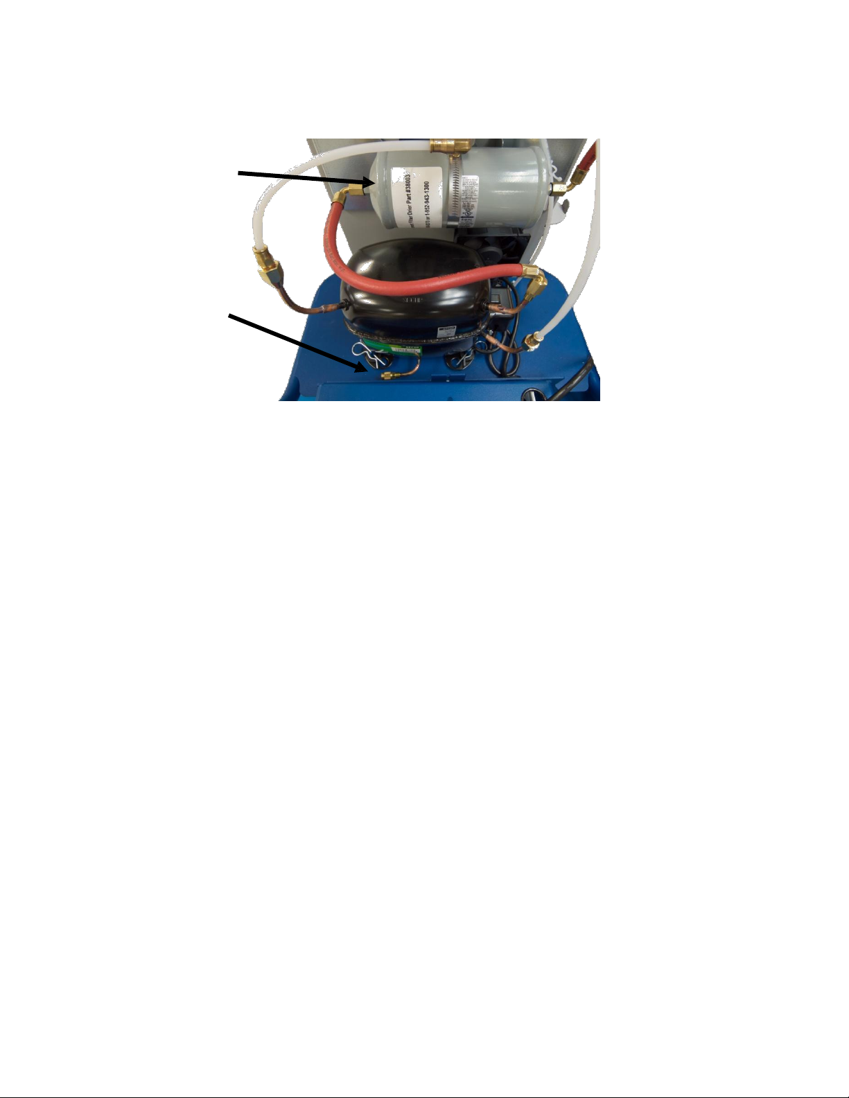
Regular Maintenance
Filter Drier
Compressor Oil
26
Drain
Filter Drier
MAINTENANCE WARNING! CHANGE FILTER
The 37840 and 37860 have a unique filter system
which ensures the refrigerant transferred to the
storage cylinder is clean and moisture-free. The
filters must be changed after they have processed
150lbs of refrigerant to ensure that the refrigerant
being processed meets purity requirements. A
maintenance reminder will prompt you when to
change your filter. All refrigerant must be removed
from the old filter before it is removed. Follow the
filter change procedures carefully to minimize
refrigerant loss and to ensure only clean, moisturefree refrigerant is transferred into the storage tank.
DRIER
SAE standards require that the further function of
the machine is disabled (locked out) if the filter drier
is not replaced at the proper interval. The unit will
prompt you when the filter is near the end of its life.
When the filter drier has processed 100 lbs (45.36
kg) of refrigerant it will warn the user that it is
nearing the end of its life. When the filter drier has
processed 150 lbs (680.4 kg) of refrigerant, the
machine will lock the user out and will require a
filter change before the unit can be used again. The
filter driers are marked with a unique code that will
be required to unlock the unit. Each filter and filter
code may only be used once.
Filter Change Procedure
Follow these steps to change the filter drier
1. From the main menu enter MACHINE
MAINTENANCE.
2. Select filter change.
3. The machine will now go through a clearing
procedure to prevent refrigerant loss.
4. When prompted, turn off and unplug the
unit.
5. Remove front covers of unit (2 bolts and 2
wing nuts).
6. Slowly loosen and detach the hoses from
the old filter.
7. Write down the filter code as printed on the
new filter.
8. Install the new filter and attach the hoses
making sure it is in the proper orientation
(the arrow should point towards the
compressor) and that the fittings are tight.
9. Replace the front covers.
10. Plug the machine in and power it on.
11. When prompted enter the filter code as
printed on the new filter.
12. The display should read “FILTER LIFE
CLEARED PRESS RESET TO
CONTINUE”.
13. The machine is now ready to continue
service.
38
Page 27

27
Compressor Oil
It is recommended to change the compressor oil
regularly. The machine automatically keeps track of
the run time of the compressor and will pop up the
following alert after a set interval.
MAINTENECE WARNING! CHANGE
COMPRESSOR OIL
The oil in the compressor should be
checked for contamination and proper
oil level when the compressor oil
maintenance reminder is displayed.
Select RESET to turn reminder off
until the next time you start the unit.
Select ENTER when the oil has been
changed
Instructions for Compressor Oil Maintenance
Oil Level Check
1. Place unit on a level surface
2. Run a recovery cycle with the unit not
connected to a vehicle.
3. Turn off and unplug the unit.
4. Remove front covers of unit.
5. SLOWLY remove oil port cap on
compressor.
Note: High pressure may be present, remove cap
slowly.
6. Place an oil pan or similar method for
collecting the oil under the oil drain port.
7. Place rear wheels of unit on a 2 x 4.
8. Oil should drip out of oil drain port.
9. If oil runs out of port rapidly, allow the oil to
drain until it is slowly dripping out.
10. Replace oil port cap and cover.
11. Replace the side covers.
12. Discard used lubricant per applicable
federal, state and local requirements.
Compressor Oil Replacement Procedure
1. Place unit on a level surface
2. Run a recovery cycle with the unit not
connected to a vehicle.
3. Turn off and unplug the unit.
4. Remove front covers of unit.
5. Carefully disconnect and remove the
onboard tank.
6. SLOWLY remove oil port cap on
compressor.
Note: High pressure may be present, remove cap
slowly.
7. Place an oil pan or similar method for
collecting the oil under the oil drain port.
8. Lock the front wheels and carefully tilt unit
at 45° angle towards oil drain port and allow
all oil to be drained.
Warning! Unit is heavy. Take care when tilting unit
to prevent injury or damage.
9. Replace the oil drain cap.
10. With the unit back on level ground refill with
proper amount and type of oil through the
compressor suction port. The proper oil
charge is 16.0 ounces of 150 VISCOSITY
(SUS) POE oil. If you are unsure of the
amount of oil added to the compressor
follow the instructions for an Oil Level
Check to ensure a proper oil fill.
11. Reconnect the compressor suction hose
and replace the front covers.
12. Discard used lubricant per applicable
federal, state and local requirements
An alternative method to changing the
compressor oil is to remove the compressor
from the machine for service
1. First, place the unit on a level surface.
2. Run a recovery cycle with the unit not
connected to a vehicle.
3. Turn off and unplug the unit and remove the
front covers.
4. Next, slowly unscrew the red hose from the
filter to the compressor and disconnect the 2
plastic hoses at the quick connectors.
5. Remove the electrical cover by inserting a
standard screw driver into the slots and
prying inward until the cover comes loose.
6. After noting the position of the white, black,
and green wires, disconnect them.
7. Now, remove the 4 clips holding the
compressor to the frame and remove the
compressor.
8. Place the compressor on a bench with an oil
drain pan below. Remove the oil drain cap
and drain the oil from the compressor by
tilting it forward at a 45 degree angle.
9. Then place the compressor on a flat surface
and fill it with 16 ounces of POE oil or until
it’s just dripping from the oil drain.
10. And, finally, reinstall the compressor.
38
Page 28

Note: Failure to perform oil maintenance can cause
the compressor to overfill with oil and severely
damage the compressor.
Another method is to remove the compressor from
the machine and service it on a bench and then
reinstall the compressor.
Vacuum Pump Oil
It is recommended to change the vacuum pump oil
regularly. The machine automatically keeps track of
the run time of the vacuum pump and will pop up
the following alert after a set interval.
MAINTENANCE WARNING! CHANGE VACUUM
PUMP OIL.
Select ENTER to turn the reminder off until the next
time you start the unit. Select RESET when the oil
has been changed. For additional vacuum pump
care see the vacuum pump manual that was
included with the machine.
28
Vacuum Pump Oil Level Check
While the vacuum pump is running the normal oil
level should be 1/2 to 5/8 up in the sight glass. This
level is necessary for proper operation.
Vacuum Pump Oil Replacement Procedure
This maintenance is best performed when the oil is
warm.
1. Remove thumb screws under vacuum pump
platform and the vacuum pump hose.
2. Tilt the vacuum pump at a 45° angle
towards the drain plug.
3. Place a container under the oil drain plug
and remove the oil drain plug.
4. Drain oil into a container.
5. Discard used lubricant per applicable
federal, state and local requirements.
6. Replace the oil drain plug and refill the
vacuum pump with YELLOW JACKET
Vacuum Pump oil 93192 to the correct level.
7. Replace the vacuum pump to its original
position and reinstall the thumb screws and
hose.
38
Page 29
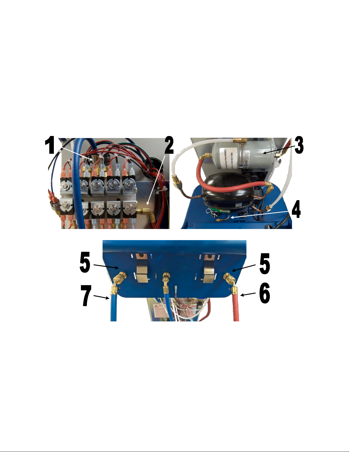
1.
Tank liquid hose
5.
Vehicle Hose Bulkhead Fittings
2.
Tank vapor hose
6.
Vehicle High Side Hose
3.
Filter Drier
7.
Vehicle Low Side Hose
4.
Compressor Oil Drain
Changeover Procedure
The 37840 has been designed to meet SAE J3030 requirements such that the machine can undergo a onetime changeover procedure that will enable the 37840 to change from only being able to service R-134a to
only being able to service R-1234yf. To perform the change over, conversion kit PN 37845 is needed which will
contain the parts necessary to convert the machine from a R-134a unit to a R-1234yf unit. Compressor oil not
included. Reminder SAE standards require the use of a refrigerant identifier for units running R-1234yf.
To change a factory default 37840 unit from the setting of R-134a to R1234yf the following procedure is to be
performed.
1. Select MACHINE CONVERSION from the
Machine Maintenance menu.
2. When prompted connect the hose flush
adapter to the vehicle service hoses and
press ENTER to start a hose flush.
3. When prompted close the tank liquid valve.
4. After the hose flush, the machine will now
confirm that you wish to change
refrigerants. REMEMBER THIS CAN NOT
BE UNDONE.
5. Follow the onscreen instructions to perform
a hose flush and system clearing procedure.
6. After the hoses have been flushed, turn
off the machine and close the vapor
valve on the tank then remove the tank
from the machine.
29
38
Page 30

7. Use a separate refrigerant recovery
machine on the tank hoses to remove any
remaining refrigerant from the tank hoses
such as the YELLOWJACKET LTE 95730.
CAUTION: Failure to recover the refrigerant from
the tank hoses may result in high pressure being
present in these hoses which could lead to user
injury or damage to the machine.
Note: During the mechanical portion of the
changeover procedure the tablet and App do not
need to be on. The App will automatically pick up
where it left off when reconnected.
8. Unplug the machine then remove the 4 bolts
to remove the top console and the 2 bolts
and 2 wing nuts to remove the front
shrouds.
9. Carefully disconnect the red and blue tank
hoses from the manifold block.
10. Disengage the black hose retainers and
remove the two tank hoses.
11. Disconnect and remove the two plastic
hoses running from the Vehicle Hose
Bulkhead Fittings and from where they
connect to the manifold. To disconnect the
hoses push the hose into the fitting then
push the fitting collar into the fitting before
pulling the hose free.
12. Remove the vehicle hose bulkhead fittings.
13. Remove the filter drier hoses and filter drier.
14. Remove any additional aftermarket
refrigerant filters.
15. Dispose of all removed hoses in an
environmentally friendly manner and
according to local laws.
16. Drain and replace the compressor oil by
following the Compressor Oil Replacement
Procedure on page 29.
17. Write down the filter code as printed on the
new filter.
18. Install the new filter and filter drier hoses
making sure the filter drier is in the proper
orientation (the arrow should point towards
the compressor) and that the fittings are
tight.
30
19. Install the new R-1234yf vehicle hose
bulkhead fittings.
20. Install the new plastic hoses into the
bulkhead fitting and back into the
corresponding manifold location.
Note: Make sure to firmly push the plastic hose
all the way into the fitting and give a gentle tug
to make sure the hose is properly installed and
engaged.
21. Feed the tank hoses through the plumbing
panel snapping the hose retainers into
place.
22. Connect the tank hoses to the manifold and
ensure the ball valves on the ends of the
hoses are closed.
23. Connect the new R-1234yf vehicle hoses.
Note: Remember to check all of the hose
connections and make sure that they are secure
and will not leak before reassembling the machine.
Also remember to properly reconnect any electrical
components you may have disconnected as well.
24. Make a note of the filter drier code then
replace the front shrouds and top console.
25. Plug the machine back in and turn it on.
26. The machine will now ask to confirm that all
the necessary hoses have been changed.
27. After you have confirmed that the necessary
changes have been performed, the machine
will go into a 30 minute vacuum cycle to
ensure that there is no cross contamination
between the refrigerants.
28. After the vacuum cycle, the machine will ask
for the new filter drier code. Enter the new
filter drier code.
29. Install the new R-1234yf tank
Note: R-1234yf tank fittings use left-hand-threaded
fittings.
30. Perform a tank refill before beginning
service.
38
Page 31

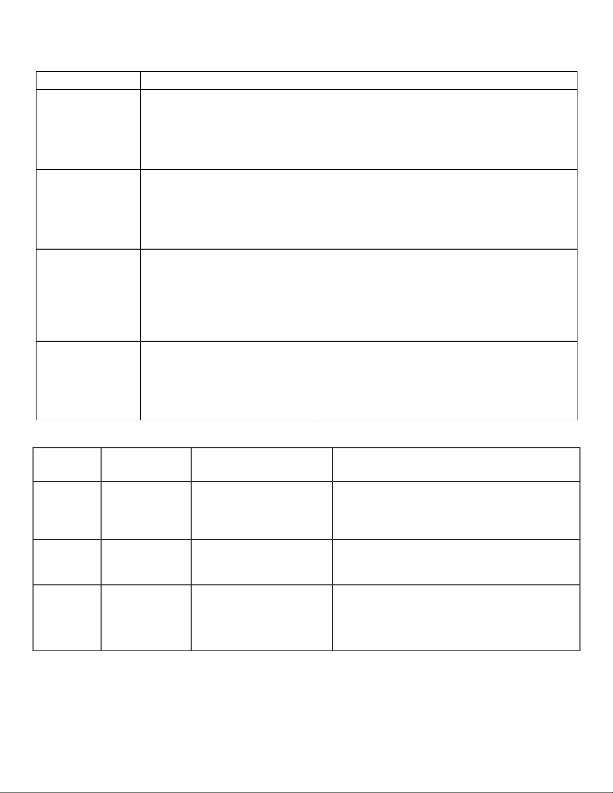
Problem
Possible Causes
Possible Solutions
Unit cannot pull
automobile A/C
system into a
vacuum.
Automobile A/C system has a
leak.
Service valves on hoses not
properly installed.
Service ball valve seals are
worn.
Hoses on unit are loose or leak.
Vacuum pump is not turned on.
Find and repair leak in A/C system.
Check valve seals and threads and replace if
needed.
Replace valve seals and Schrader core depressor.
Tighten or replace hoses on unit.
Turn on vacuum pump.
High side gauge
readings above
normal.
Restriction in A/C system or
Schrader core.
Service hose ball valve closed.
Incorrect charge amount entered
in unit.
Check hose connection and fix restriction.
Replace Schrader core.
Open the valve.
Recover, check scale calibration, and recharge
system.
Refrigerant not
being transferred
during Tank Refill.
Valve on supply tank closed.
Ball valve on blue service hose
closed or hose is constricted.
Wrong hose installed on new
refrigerant tank.
Storage tank is full.
Open valve.
Open valve or straighten hose.
Install blue service hose on refrigerant tank.
Close valve on new supply. Disconnect service
hose.
Unit will not accept
commands.
App is frozen.
The machine is not connected to
the tablet/app.
The tablet became unpaired
from the machine.
Machine is not powered on.
Control board malfunction.
Close out of the App and restart.
Restart the machine and the app then wait to hear
the beep from the machine confirming connection
Open Bluetooth settings in the tablet and re-pair
the tablet with the machine.
Turn on machine.
Call Technical Support.
Fan not running/fan
lockout.
Loose power wire to fan.
Fan airflow is blocked or fan
blades stuck.
Control board malfunction.
Fan malfunction.
Locate loose fitting and reconnect.
Remove obstruction from fan.
Call Technical Support.
Call Technical Support.
Unit will not turn on.
Power cord is not plugged into a
120 Volt outlet.
Tablet battery is dead.
Circuit breaker tripped on shop
power panel.
Bad Main Power switch.
Loose wire.
Plug into outlet.
Charge tablet.
Reset circuit breaker. If circuit breaker immediately
trips, do not reset. Consult a qualified electrician.
Call Technical Support.
Repair loose wire.
Troubleshooting Information
The 37840 and 37860 have a number of
sophisticated features which make it easy to
perform fast and efficient service. Although these
units are manufactured with high quality
components, a component failure could cause it to
operate incorrectly.
Common Problems and Potential Solutions
31
The following section is designed to provide you
with additional information to help diagnose the
system. If a problem occurs, please read this
section thoroughly prior to calling technical support.
This will reduce the time needed to restore your
system to normal operation. Please call technical
support number at (800)769-8370.
38
Page 32
32
Malfunction of control board.
Call Technical Support.
Unit will not recover
refrigerant from A/C
system.
Valves on service hoses shut.
Service hose is constricted.
Unit storage tank valve is closed.
Tablet is not connected to the
unit.
Compressor not operating.
Open valves.
Straighten hose.
Open tank valves.
Make Bluetooth connection between the tablet
and the unit.
Call Technical Support.
Unit will not charge
refrigerant into
vehicle.
Valves on service hoses shut.
Service hose is constricted.
Unit storage tank valve is closed.
Hoses to unit storage tank not
connected to the correct tank
valves
Open valves
Straighten hose
Open tank valves
Make sure the blue tank hose is connected to the
tank liquid port and the red tank hose is connected
to the tank vapor port.
Refrigerant leaking
during charging.
Service valves on hoses not
properly installed on A/C system.
Service ball valve seals are
worn.
Hoses on unit are loose or leak.
Automobile A/C system has a
leak
Check valve seals and threads and replace if
needed.
Replace valve seals and Schrader core depressor
Tighten or replace hoses on unit
Find leak in A/C system and repair.
Weight
measurements from
unit are not correct.
Tank hoses improperly installed.
Scale calibration has drifted.
Scale is damaged and cannot
be calibrated.
Ensure tank hoses are not pinched or rubbing on
the machine frame.
Check scale calibration and recalibrate if
necessary.
Call Technical support
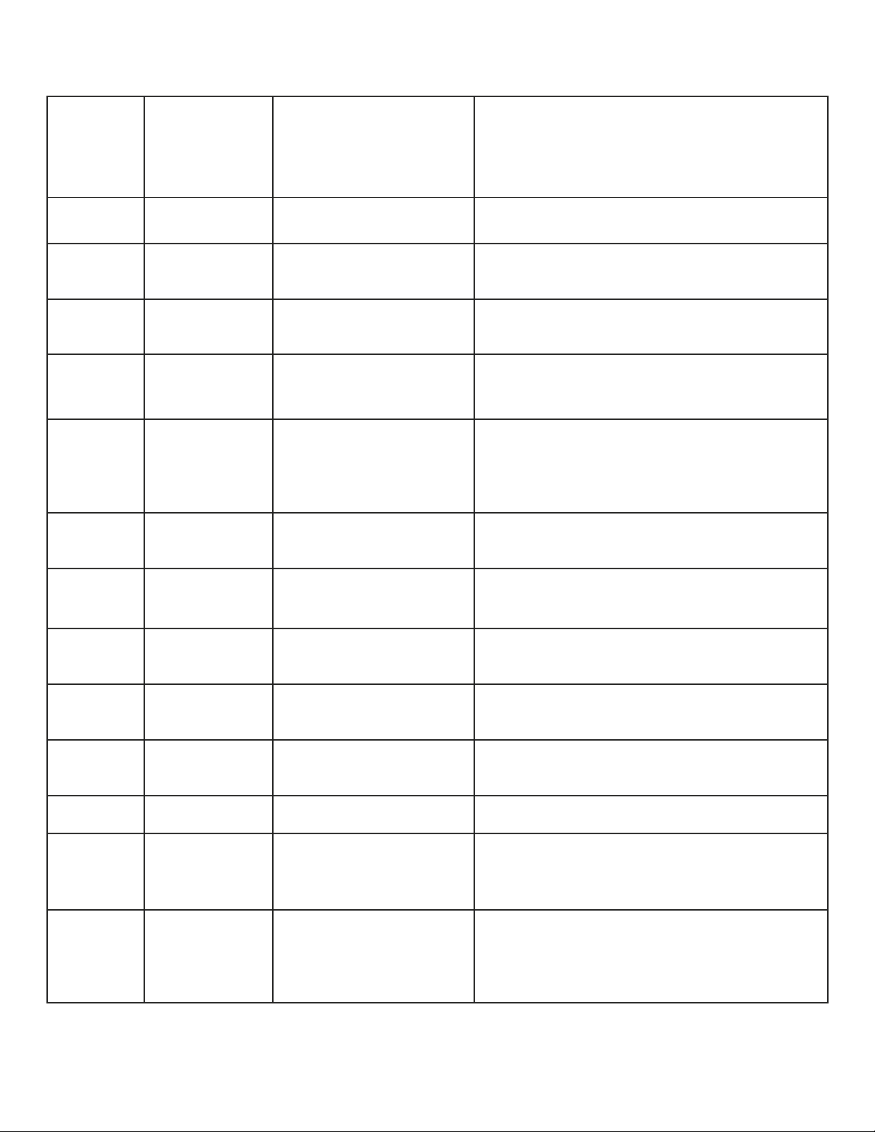
ERROR
NUMBER
MESSAGE
DESCRIPTION
TROUBLESHOOTING
ERROR 1
HIGH
PRESSURE
HIGH PRESSURE
SWITCH IS TRIPPED
(NORMALY CLOSED
SWITCH)
MAKE SURE TANK VALVE IS OPEN
TEST HIGH PRESSURE SWITCH
CHECK SV AND CHECK VALVE OP
CHECK TANK PRESSURE
ERROR 2
TANK FULL
TANK WEIGHT OVER
80% OF CAPACITY
CHECK SCALE CALIBRATION
REMOVE SOME REFRIGERANT FROM
STORAGE TANK
ERROR 3
RECOVERY
TIME OUT
RECOVERY PROCESS
HAS EXCEEDED 1 HR
FACTORY DEFAULT
IF AC SYSTEM CONTAINS MORE THAN 3
LBS OF REFRIGERANT INCREASE
DEFAULT TIME
CHECK FOR LEAKS (HOSES, FITTINGS
AND AUTO AC SYSTEM)
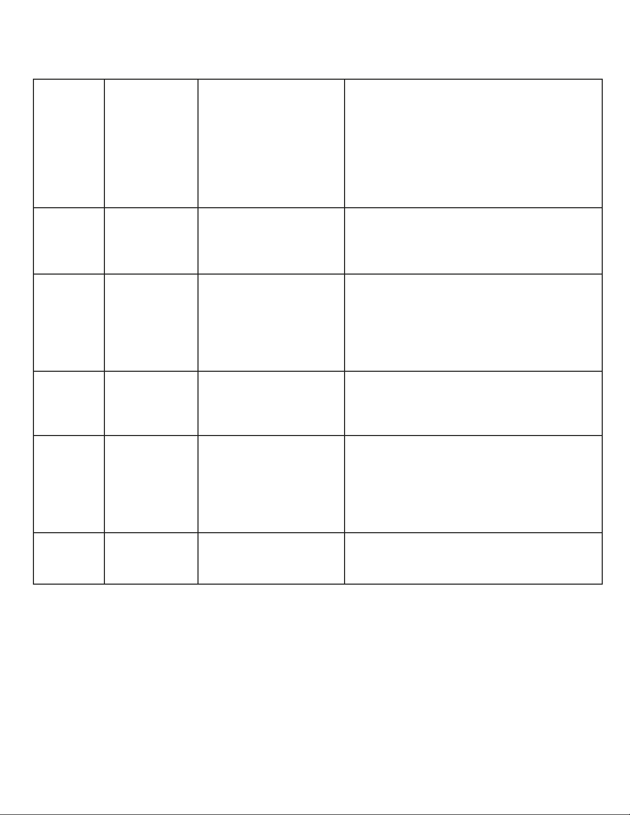
Error Messages
Page 33
33
ERROR 4
CHARGING
TIME OUT
CHARGING PROCESS
HAS EXEEDED 20 MIN
FACTORY DEFAULT
OPEN TANK VALVES
OPEN SERVICE COUPLERS
SWITCH TO LOW SIDE CHARGING
CHECK TANK WEIGHT (10 LB MIN)
INCREASE VACUUM TIME
ERROR 5
NO TANK ON
SCALE
SCALE NOT READING
TANK WEIGHT
PLACE TANK ON SCALE
CHECK SCALE CALIBRATION
ERROR 6
TANK EMPTY
REFRIGERANT AMOUNT
BELOW 5 % OF TANK
CAPACITY
REFILL TANK
CHECK SCALE CALIBRATION
ERROR 7
NOT ENOUGH
REFRIGERANT
UNIT IS LOW ON
REFRIGERANT
(10 LB MIN)
REFILL ONBOARD REFRIGERANT TANK
ERROR 8
TANK REFILL
TIME OUT
TANK REFILL HAS
EXCEEDED
DEFAULT TIME
RUN TANK REFILL MODE AGAIN
CHECK FOR LEAKS
ERROR 10
SYSTEM
EQUALIZED
PRESSURE EQUALIZED
DURING CHARGING
INCREASE VACUUM TIME
CHANGE TO LOW SIDE CHARGE, CLOSE
THE HIGH SIDE VEHICLE FITTING, AND
RUN THE VEHICLE TO DRAW IN THE
REMAINING REFRIGERANT CHARGE
ERROR 11
HOSE
CLEARING
TIME OUT
CLEARING TIME OUT
AFTER CHARGING
CLOSE SERVICE VALVES AND
DISCONNECT
ERROR 12
SCALE
MALFUNCTION
SCALE NOT READING
TANK PROPERLY
CHECK TANK PLACEMENT
CHECK SCALE CALIBRATION
REPLACE SCALE ASSEMBLY
ERROR 13
VACUUM
ERROR
R-134a SYSTEM NOT
MAINTAINING PROPER
VACUUM LEVEL
CHECK SYSTEM FOR LEAKS
INCREASE VACUUM TIME
ERROR 14
LEAK CHECK
FAILED
SYSTEM NOT HOLDING
PROPER VACUUM
LEVEL
CHECK SYSTEM FOR LEAKS
INCREASE VACUUM TIME
ERROR 15
SOLENOID
MALFUNCTION
SOLENOID
COMMUNICATION
ERROR
CHECK SOLENOID CONNECTIONS
REPLACE FAULTY SOLENOID
ERROR 16
SCALE
CALIBRATION
SCALE CALIBRATION
MAY HAVE CHANGED
RECALIBRATE ONBOARD SCALE
ERROR 17
STABILIZING
ERROR
SCALE READINGS NOT
STABILIZING
DO NOT MOVE MACHINE WHILE SCALE IS
STABILIZING
CALIBRATE SCALE
REPLACE SCALE
ERROR 19
UNIDENTIFIED
PRESSURE
DETECTED
MACHINE HAS
DETECTED PRESSURE
WHILE TRYING TO PULL
A VACUUM
ON R-1234yf MACHINES IF THE PRESSURE
IN THE SYSTEM IS ABOVE ATMOSPHERIC
PRESSURE THEN THE SYSTEM MUST BE
RECOVERED TO BELOW ATMOSPHERIC
PRESSURE BEFORE VACUUM CAN
Page 34
34
ERROR 19
OCCUR
CLOSE THE VEHICLE SERVICE
COUPLERS AND ALLOW MACHINE TO
CLEAR THE HOSES VIA THE VACUUM
PUMP
FOLLOW THE PROPER RECOVERY
PROCEDURE BEFORE PROCEEDING TO
THE VACUUM CYCLE
ERROR 20
IDENTIFIER
CALIBRATION
ERROR
IDENTIFIER COULD NOT
CALIBRATE
ENSURE IDNTIFIER IS DICONNECTED
FROM ANY REFIGERANT SOURCE
DURING CALIBRATION
CHECK IDENTIFIER FILTER
ERROR 21
SYSTEM
UNDER
PRESSURE
PRESSURE
TRANSDUCERS ARE
UNDER PRESSURE
WHILE MACHINE IS
ATTEMPTING TO ZERO
ENSURE BLUE VEHICLE HOSE IS
DISCONNECTED FROM THE MACHINE
AND THAT THE RED VEHICLE HOSE IS
DISCONNECTED FROM ANY
REFRIGERANT SOURCE
REPLACE PRESSURE TRANSDUCERS
ERROR 22
VACUUM
ERROR
R-1234yf REQUIRED
VACUUM LEVEL NOT
REACHED OR NOT
MAINTAINED
CHECK SYSTEM FOR LEAKS
INCREASE VACUUM TIME
ERROR 23
REFEGERANT
PURITY FAIL
IDENTIFIER HAS
DETECTED
CONTAMINATED
REFRIGERANT
RECALIBRATE IDENTIFIER AND TRY
IDENTIFICATION AGAIN
RECOVER CONTAMINATED
REFRIGERANT USING MACHINE
DESIGNED TO HANDLE CONTAMINATED
REFRIGERANT
ERROR 24
FAN SPEED
PROBLEM
FAN IS RUNNING AT AN
IRREGULAR SPEED
CHECK FAN FOR OBSTRUCTIONS
CHECK FAN WIRING
REPLACE FAN
Page 35
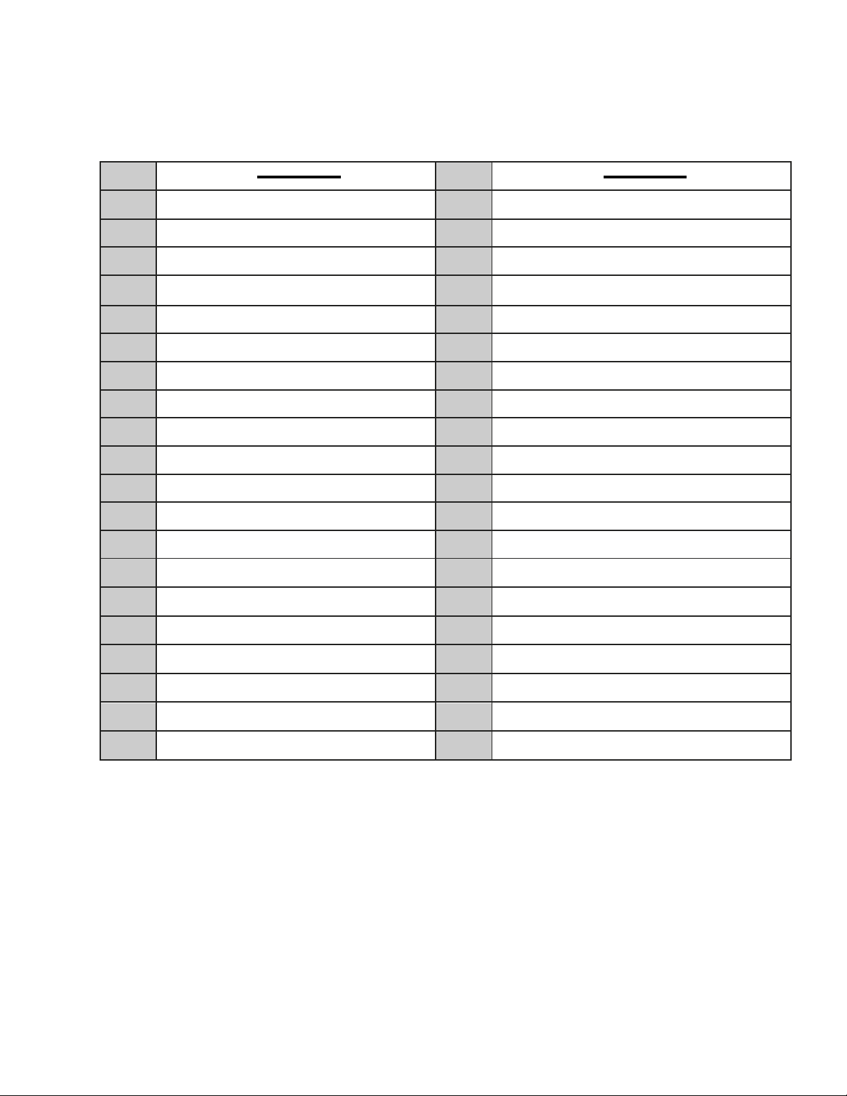
Part #
Description
Part #
Description
41301
R-134a High Side Coupler
41441
R-1234yf High Side Coupler
41302
R-134a Low Side Coupler
41442
R-1234yf Low Side Coupler
01215
R-134a Auto Low Side Blue Hose (10ft)
17830
R-1234yf Auto Low Side Blue Hose (10ft)
01216
R-134a Auto High Side Red Hose (10ft)
17870
R-1234yf Auto High Side Red Hose (10ft)
19240
R-134a Tank Vapor Red Hose
19234
R-1234yf Tank Vapor Red Hose
19241
R-134a Tank Liquid Blue Hose
19243
R-1234yf Tank Liquid Blue Hose
36211
R-134a Tank Refill Adapter
19244
R-1234yf Tank Refill Adapter
95026
R-134a 50lb Refrigerant Tank
95028
R-1234yf 50lb Refrigerant Tank
37842
R-134a Oil Injector
37862
R-1234yf Oil Injector
38132
R-134a Hybrid Hose Flush Adapter
19245
R-1234yf Hybrid Hose Flush Adapter
67008
R-134a Automotive ManTooth
67009
R-1234yf Automotive ManTooth
38019
Oil Bottle
37845
37840 R-134a to R-1234yf Changeover Kit
95157
Circuit Breaker, 15 Amp
93192
Vacuum Pump Oil
38113
Automatic Scale Assembly
37913
Dust Cover
95423
High Pressure Switch
37911
Replacement Tablet
38003
Filter-Dryer (1 per unit)
37865
Refrigerant Identifier
38155
Caster Wheels (2 pack)
69336
Refrigerant Leak Detector
19246
500g Scale Check Weight
19239
Replacement Magnet Set
19247
Replacement Side Hooks
Repair Parts List
Page 36

Limited Warranty for 37840 & 37860
EXCLUSIVE WARRANTY – LIMITATION OF LIABILITY
The Limited Warranty is the only Warranty for this unit given by Ritchie Engineering Company Inc. No one is authorized to make any other
warranties on our behalf. Ritchie Engineering’s sole liability, with respect to any defect, shall be set forth in this limited warranty, and any
claims for incidental or consequential damages are excluded. Some states do not allow limitations on how long an implied warranty last, or
for the exclusion of incidental or consequential damages, so the above limitations or exclusions may not apply to you.
This Limited Warranty gives you specific legal rights, and you may also have other rights, which vary from state to state.
Reasonable proof of the date of purchase of your Refrigerant Management System may be required to establish its “in-warranty” status.
Otherwise, the effective date of this Limited Warranty will be the date of sale to Distributor.
GENERAL
Ritchie Engineering Company Inc. warrants its product to be free from factory defects in materials and workmanship, under normal use
and service, for the applicable warranty period. At its option Ritchie Engineering Company Inc. will credit, repair or replace the defective
Refrigerant Management System, or defective component part(s), in accordance with the terms of this Limited Warranty, if it fails in normal
use and service during the applicable warranty period. The replacement Refrigerant Management System must be manufactured by Ritchie
Engineering. The replacement component part(s) must be Ritchie Engineering authorized component part(s). The replacement unit will be
warranted only for the unexpired portion of the original unit’s applicable warranty period.
WARRANTY EXCLUSIONS
This Limited Warranty will not cover:
1) Service trips to teach you how to install, use or maintain this Refrigerant Management System.
2) Damages, malfunction or failures resulting from failure to maintain clean uncontaminated oil in the Vacuum Pump and
Compressor.
3) Damages, malfunctions, or failures resulting from improper installation or failure to operate and maintain the Refrigerant
Management System in accordance with the manufacturer’s instructions provided.
4) Damages, malfunctions, or failures caused by misuse, abuse, accident, fire, flood, freeze, lightning, acts of God, and the like.
5) Damages, malfunctions, or failures caused by operating the Management Refrigerant System with modified, altered, or
unapproved parts installed.
THE EFFECTIVE DATE
The effective date of warranty coverage (or the beginning of the Applicable Warranty Periods) is the date of purchase of the
Refrigerant Management System, if properly documented. If you are not able to provide the documentary proof of the date of
original purchase, the effective date will be the date of sale to the Distributor.
APPLICABLE WARRANTY PERIODS
Ritchie Engineering Company Inc. YELLOW JACKET Refrigerant Management Systems part number 37840 and 37860 is covered by a one
year warranty for parts and labor. The Vacuum Pump has a standard 2 year parts and labor warranty.
BEFORE REQUESTING SERVICE
Please review the applicable technical documentation to insure proper installation and correct customer control for the system. If the
problem persists, please arrange for warranty service.
TO OBTAIN WARRANTY SERVICE
Promptly contact Ritchie Engineering Company Inc. at 1-800-769-8370 for service, repair or return. If service cannot be completed over
the phone and/or through Remote Access Troubleshooting by Ritchie Engineering Company’s Technical Services an Independent Service
Center may be dispatched. If return is required you must obtain an authorization number prior to return. All returns must be PREPAID.
Test Equipment Depot - 800.517.8431 - 99 Washington Street Melrose, MA 02176
TestEquipmentDepot.com
 Loading...