

Page 1
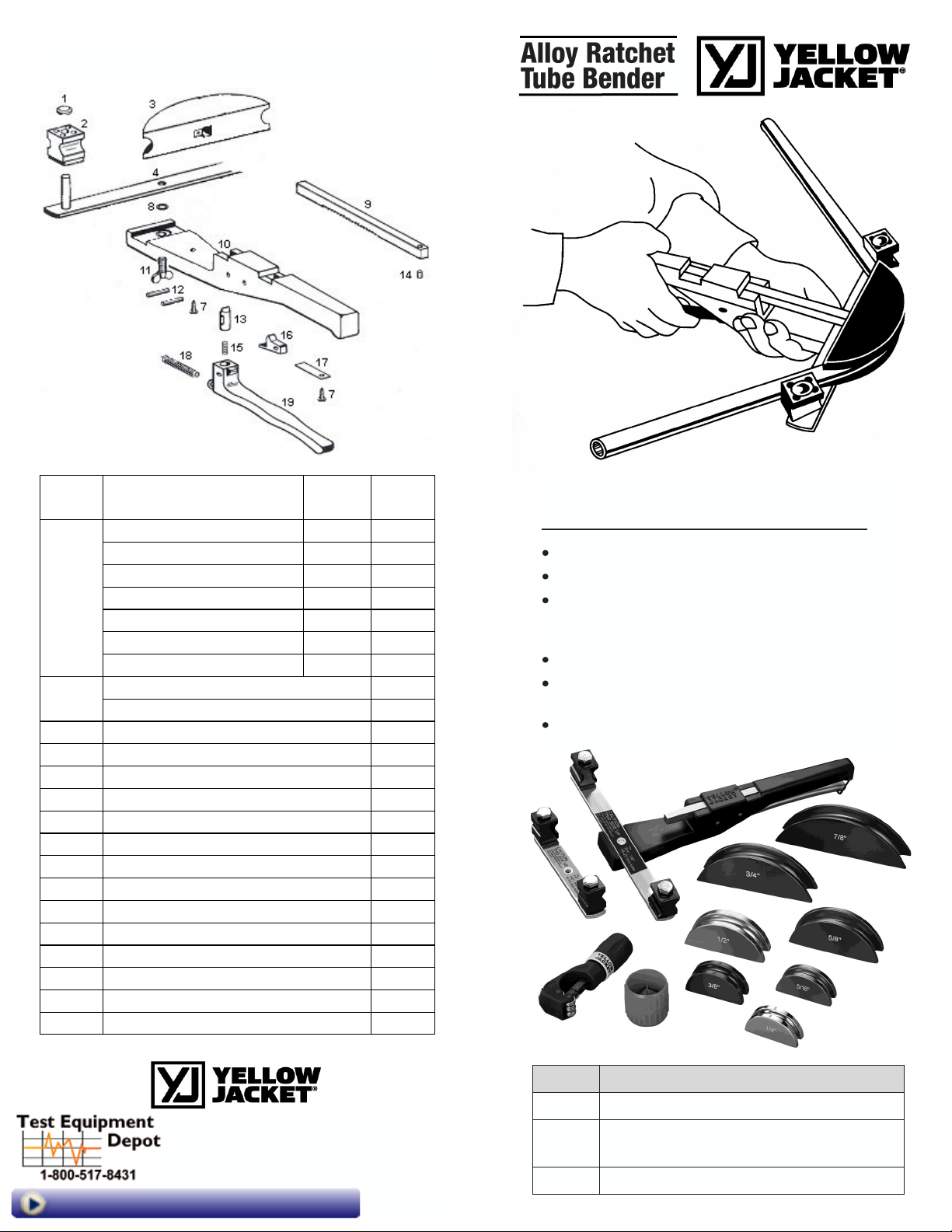
Replacement Parts (Exploded View)
P/N 733329 RevA
Diagram
Number Description
Bending
Radius
Part
Number
3
Alloy Bending Mandrel - 1/4" 1" 63326
Alloy Bending Mandrel - 5/16" 1-1/8" 63327
Alloy Bending Mandrel - 3/8" 1-1/4" 63332
Alloy Bending Mandrel - 1/2" 1-1/2" 63333
Alloy Bending Mandrel - 5/8" 1-1/2" 63334
Alloy Bending Mandrel - 3/4" 1-3/4" 63335
Alloy Bending Mandrel - 7/8" 2" 63336
1, 2, 4
Crossbar Assembly 3/4" to 7/8" 63329
Crossbar Assembly 1/4" to 5/8" 63330
7 Fillister Head Screw 60328
8, 11 Wing Nut & E-Clip 60348
9, 14 Ratchet Bar & Catch Bolt 63340
10 Bender Body Housing 60343
12 Spiral Pins N/A
13, 15 Catch Pin & Spring 60344
16 Catch Lever 60345
17 Flat Spring 60346
18 Tension Spring 60349
19 Feed Lever 60347
7-19 Ratchet Body Assembly 63339
N/A Plastic Carrying Case 63338
N/A Small Cutter for 1/8" to 1-1/8" OD 60101
N/A Tube Reamer - 1/16" to 1-3/8" 60161
Easy one hand bending of 1/4” to 7/8” soft copper,
aluminum and light wall hydraulic tubing.
Hard copper must be annealed before bending.
Quick change bending mandrels and shoes
Trouble free ratchet mechanism
Complete tube bender kit includes all items
required to bend 1/4”, 5/16”, 3/8”, 1/2”, 5/8”,
3/4” and 7/8” tubing
Color code Alloy Mandrels
Simple and secure mandrel attachment with
ball-detent feature
Smooth and consistent bends every time
UPC# Description
63331 Alloy Ratchet Tube Bender Kit
63325 Deluxe Alloy Ratchet Tube Bender Kit
(includes 63342 Reverse Bender)
63342 Reverse Bender for 63331
Visit us at www.TestEquipmentDepot.com
5 Commonwealth Ave
Woburn, MA 01801
Phone 781-665-1400 Toll
Free 1-800-517-8431
Page 2
Operating Instructions
Preparing Unit for Operation
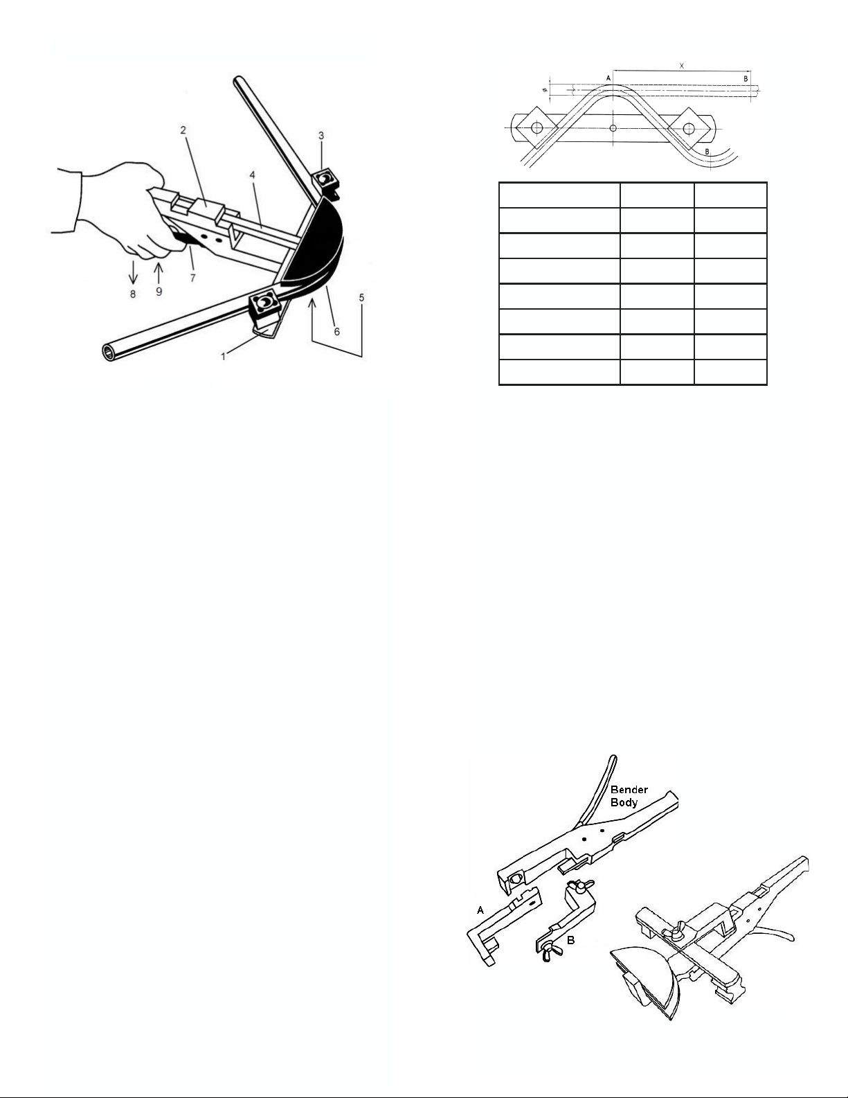
Choose the desired size bending mandrel (6) and
slide the square hole on the ratchet bar (4).
Fasten the correctly sized crossbar assembly (1)
on the bender body (2), so that the desired size
bending shoes (3) are in the same plane as the
mandrel. Use the wing screw (5) to fasten. The
bending shoes are marked with the various tube
sizes. Rotate the desired size shoe to face the
bender handle. Pull the feed lever (7) away from
the handle in the indicated direction (8) and push
the mandrel and ratchet bar back towards the
handle. Release feed lever (7). You are now
ready to bend tubing.
Bending Operation
Put your tubing between the mandrel and bending shoes making sure the bending shoe (3) and
mandrel (6) are matched for size. Squeeze the
feed lever a few times in the indicated direction
“(9)” to begin the bend. When the bender is in the
desired position, continue squeezing the lever
until the bend is complete. To remove the tube,
pull the feed lever (7) away from the handle in the
indicated direction (8), push the mandrel back
toward the handle and take the tubing out.
CAUTION: Annealed tubing should be cooled prior to bending so bending mandrel and bending
shoes are not damaged.
Tool Maintenance
This unit is maintenance free, no service is
required.
(Figure 1)
Minimum Distance Between Bends
Optional Reverse Bending Kit 63342
(included in Deluxe Alloy Ratchet Tube Bender Kit 63325)
To bend tubing from the outside of the bend, the
Reverse Bender Kit 63342 (mounts on the
bender handle) is required.
Adapter “A” attaches to the end of the bender
body (Figure 2) where the correctly sized crossbar is normally fastened.
Adapter “B” mounts to the end of the square
ratchet bar (4). The bending mandrel is installed
onto the square at the end of the “A” adapter.
The crossbar is fastened with the screw to the
end of adapter “B” (See Figures 1, 2 & 3).
The bend alignment and bending are done as in
Figure 1.
Figure 2
Tubing Diameter Inches (mm)
1/4” 4” 102
5/16” 4” 102
3/8” 5” 127
1/2” 5” 127
5/8” 5.5” 140
3/4” 8.5” 216
7/8” 8.5” 216
Figure 3
Test Equipment Depot - 800.517.8431 - 5 Commonwealth Ave, MA 01801
TestEquipmentDepot.com
 Loading...