

Page 1

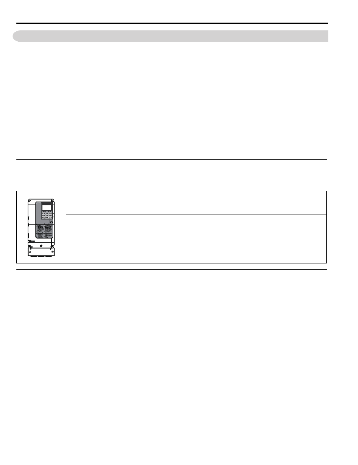
YASKAWA R1000 Series
Power Regenerative Unit
Instruction Manual
Type: CIMR-RU
Models:
To properly use the product, read this manual thoroughly and retain
for easy reference, inspection, and maintenance. Ensure the end user
receives this manual.
200 V Class, Three-Phase Input: 3.5 to 105 kW
400 V Class, Three-Phase Input: 3.5 to 300 kW
MANUAL NO. TOEP C710656 08B
Receiving
Mechanical Installation
Electrical Installation
Start-Up Programming &
Operation
Troubleshooting
Periodic Inspection &
Maintenance
Standard Configuration Devices,
Peripheral Devices, and Options
Specifications
Parameter List
MEMOBUS/Modbus
Communications
Standards Compliance
1
1
2
2
3
3
4
4
5
5
6
6
7
7
A
A
B
B
C
C
E
D
D
Page 2

Copyright © 2014 YASKAWA ELECTRIC CORPORATION. All rights reserved.
No part of this publication may be reproduced, stored in a retrieval system, or transmitted, in any form or by
any means, mechanical, electronic, photocopying, recording, or otherwise, without the prior written permission
of Yaskawa. No patent liability is assumed with respect to the use of the information contained herein.
Moreover, because Yaskawa is constantly striving to improve its high-quality products, the information
contained in this manual is subject to change without notice. Every precaution has been taken in the
preparation of this manual. Yaskawa assumes no responsibility for errors or omissions. Neither is any liability
assumed for damages resulting from the use of the information contained in this publication.
2 YASKAWA ELECTRIC TOEP C710656 08B YASKAWA Power Regenerative Unit - R1000 Instruction Manual
Page 3

Table of Contents
i. PREFACE & GENERAL SAFETY .............................................................................. 9
i.1 Preface . . . . . . . . . . . . . . . . . . . . . . . . . . . . . . . . . . . . . . . . . . . . . . . . . . . . . . . . . . . . . 10
Applicable Documentation . . . . . . . . . . . . . . . . . . . . . . . . . . . . . . . . . . . . . . . . . . . . . . 10
Symbols . . . . . . . . . . . . . . . . . . . . . . . . . . . . . . . . . . . . . . . . . . . . . . . . . . . . . . . . . . . . 10
Terms and Abbreviations . . . . . . . . . . . . . . . . . . . . . . . . . . . . . . . . . . . . . . . . . . . . . . . 10
Trademarks . . . . . . . . . . . . . . . . . . . . . . . . . . . . . . . . . . . . . . . . . . . . . . . . . . . . . . . . . 10
i.2 General Safety . . . . . . . . . . . . . . . . . . . . . . . . . . . . . . . . . . . . . . . . . . . . . . . . . . . . . . . 11
Supplemental Safety Information . . . . . . . . . . . . . . . . . . . . . . . . . . . . . . . . . . . . . . . . . 11
Safety Messages . . . . . . . . . . . . . . . . . . . . . . . . . . . . . . . . . . . . . . . . . . . . . . . . . . . . . 12
General Application Precautions . . . . . . . . . . . . . . . . . . . . . . . . . . . . . . . . . . . . . . . . . 14
Precautions on Using Peripheral Devices . . . . . . . . . . . . . . . . . . . . . . . . . . . . . . . . . . 16
Warning Label Example . . . . . . . . . . . . . . . . . . . . . . . . . . . . . . . . . . . . . . . . . . . . . . . . 16
Warranty Information . . . . . . . . . . . . . . . . . . . . . . . . . . . . . . . . . . . . . . . . . . . . . . . . . . 16
1. RECEIVING............................................................................................................... 17
1.1 Section Safety . . . . . . . . . . . . . . . . . . . . . . . . . . . . . . . . . . . . . . . . . . . . . . . . . . . . . . . 18
1.2 Model Numbers and Nameplates. . . . . . . . . . . . . . . . . . . . . . . . . . . . . . . . . . . . . . . . 19
Nameplate . . . . . . . . . . . . . . . . . . . . . . . . . . . . . . . . . . . . . . . . . . . . . . . . . . . . . . . . . . 19
Model Numbers . . . . . . . . . . . . . . . . . . . . . . . . . . . . . . . . . . . . . . . . . . . . . . . . . . . . . . 20
1.3 Regenerative Unit Models and Enclosure Types . . . . . . . . . . . . . . . . . . . . . . . . . . . 21
2. MECHANICAL INSTALLATION ............................................................................... 23
2.1 Section Safety . . . . . . . . . . . . . . . . . . . . . . . . . . . . . . . . . . . . . . . . . . . . . . . . . . . . . . 24
2.2 Mechanical Installation. . . . . . . . . . . . . . . . . . . . . . . . . . . . . . . . . . . . . . . . . . . . . . . . 25
Installation Environment . . . . . . . . . . . . . . . . . . . . . . . . . . . . . . . . . . . . . . . . . . . . . . . . 25
Installation Orientation and Spacing . . . . . . . . . . . . . . . . . . . . . . . . . . . . . . . . . . . . . . 25
Precautions and Instructions for Installation . . . . . . . . . . . . . . . . . . . . . . . . . . . . . . . . 27
Digital Operator Remote Usage . . . . . . . . . . . . . . . . . . . . . . . . . . . . . . . . . . . . . . . . . . 29
Exterior and Mounting Dimensions . . . . . . . . . . . . . . . . . . . . . . . . . . . . . . . . . . . . . . . 30
3. ELECTRICAL INSTALLATION ................................................................................ 35
3.1 Section Safety . . . . . . . . . . . . . . . . . . . . . . . . . . . . . . . . . . . . . . . . . . . . . . . . . . . . . . . 36
3.2 Standard Connection Diagram . . . . . . . . . . . . . . . . . . . . . . . . . . . . . . . . . . . . . . . . . 38
3.3 Main Circuit Connection Diagram . . . . . . . . . . . . . . . . . . . . . . . . . . . . . . . . . . . . . . . 40
2A03P5 to 2A0053, and 4A03P5 to 4A0073 . . . . . . . . . . . . . . . . . . . . . . . . . . . . . . . . 40
2A0073 to 2A0105, and 4A0105 to 4A0300 . . . . . . . . . . . . . . . . . . . . . . . . . . . . . . . . . 40
3.4 Terminal Block Configuration . . . . . . . . . . . . . . . . . . . . . . . . . . . . . . . . . . . . . . . . . . 41
3.5 Terminal Cover . . . . . . . . . . . . . . . . . . . . . . . . . . . . . . . . . . . . . . . . . . . . . . . . . . . . . . 45
Models 2A03P5 to 2A0028, 4A03P5 to 4A0028 (IP20/NEMA Type 1) . . . . . . . . . . . . 45
Models 2A0035 to 2A0105, 4A0035 to 4A0300 (IP00/Open Type enclosure) . . . . . . . 46
YASKAWA ELECTRIC TOEP C710656 08B YASKAWA Power Regenerative Unit - R1000 Instruction Manual 3
Page 4

3.6 Digital Operator and Front Cover. . . . . . . . . . . . . . . . . . . . . . . . . . . . . . . . . . . . . . . . 47
Removing/Reattaching the Digital Operator . . . . . . . . . . . . . . . . . . . . . . . . . . . . . . . . . 47
Removing/Reattaching the Front Cover . . . . . . . . . . . . . . . . . . . . . . . . . . . . . . . . . . . .47
3.7 Top Protective Cover . . . . . . . . . . . . . . . . . . . . . . . . . . . . . . . . . . . . . . . . . . . . . . . . . 49
Removing and Reattaching the Top Protective Cover . . . . . . . . . . . . . . . . . . . . . . . . . 49
3.8 Main Circuit Wiring . . . . . . . . . . . . . . . . . . . . . . . . . . . . . . . . . . . . . . . . . . . . . . . . . . .50
Main Circuit Terminal Functions . . . . . . . . . . . . . . . . . . . . . . . . . . . . . . . . . . . . . . . . . . 50
Protecting Main Circuit Terminals . . . . . . . . . . . . . . . . . . . . . . . . . . . . . . . . . . . . . . . . . 50
Wire Gauges and Tightening Torque . . . . . . . . . . . . . . . . . . . . . . . . . . . . . . . . . . . . . . 50
Ground Wiring . . . . . . . . . . . . . . . . . . . . . . . . . . . . . . . . . . . . . . . . . . . . . . . . . . . . . . . 55
3.9 Control Circuit Wiring . . . . . . . . . . . . . . . . . . . . . . . . . . . . . . . . . . . . . . . . . . . . . . . . .57
Control Circuit Terminal Block Functions . . . . . . . . . . . . . . . . . . . . . . . . . . . . . . . . . . .58
Terminal Configuration . . . . . . . . . . . . . . . . . . . . . . . . . . . . . . . . . . . . . . . . . . . . . . . . .60
Wiring the Control Circuit Terminal . . . . . . . . . . . . . . . . . . . . . . . . . . . . . . . . . . . . . . . . 61
3.10 Control I/O Connections . . . . . . . . . . . . . . . . . . . . . . . . . . . . . . . . . . . . . . . . . . . . . . .63
Terminal A2 Input Signal Selection . . . . . . . . . . . . . . . . . . . . . . . . . . . . . . . . . . . . . . . 63
Using the Contact Outputs . . . . . . . . . . . . . . . . . . . . . . . . . . . . . . . . . . . . . . . . . . . . . . 64
Connect to a PC . . . . . . . . . . . . . . . . . . . . . . . . . . . . . . . . . . . . . . . . . . . . . . . . . . . . . .65
3.11 Wiring Checklist . . . . . . . . . . . . . . . . . . . . . . . . . . . . . . . . . . . . . . . . . . . . . . . . . . . . . 66
4. START-UP PROGRAMMING & OPERATION ......................................................... 67
4.1 Section Safety . . . . . . . . . . . . . . . . . . . . . . . . . . . . . . . . . . . . . . . . . . . . . . . . . . . . . . .68
4.2 Using the Digital Operator . . . . . . . . . . . . . . . . . . . . . . . . . . . . . . . . . . . . . . . . . . . . . 69
LCD Display . . . . . . . . . . . . . . . . . . . . . . . . . . . . . . . . . . . . . . . . . . . . . . . . . . . . . . . . .69
ALARM (ALM) LED Displays . . . . . . . . . . . . . . . . . . . . . . . . . . . . . . . . . . . . . . . . . . . . 70
LO/RE LED and RUN LED Indications . . . . . . . . . . . . . . . . . . . . . . . . . . . . . . . . . . . . .70
Menu Structure for Digital Operator . . . . . . . . . . . . . . . . . . . . . . . . . . . . . . . . . . . . . . . 71
4.3 The Drive and Programming Modes . . . . . . . . . . . . . . . . . . . . . . . . . . . . . . . . . . . . . 72
Navigating the Drive and Programming Modes (Default Setting) . . . . . . . . . . . . . . . . . 72
Changing Parameter Settings or Values . . . . . . . . . . . . . . . . . . . . . . . . . . . . . . . . . . .73
Verifying Parameter Changes: Verify Mode . . . . . . . . . . . . . . . . . . . . . . . . . . . . . . . . .74
Switching Between LOCAL and REMOTE . . . . . . . . . . . . . . . . . . . . . . . . . . . . . . . . . . 74
4.4 Powering Up the Regenerative Unit. . . . . . . . . . . . . . . . . . . . . . . . . . . . . . . . . . . . . . 76
Powering Up the Regenerative Unit and Operation Status Display . . . . . . . . . . . . . . .76
4.5 Operation with the Drive Connected . . . . . . . . . . . . . . . . . . . . . . . . . . . . . . . . . . . . . 77
Drive Connection Example . . . . . . . . . . . . . . . . . . . . . . . . . . . . . . . . . . . . . . . . . . . . . . 77
Timing Chart for Turning the Power Supply On and Off . . . . . . . . . . . . . . . . . . . . . . . .77
Operation Command Selection . . . . . . . . . . . . . . . . . . . . . . . . . . . . . . . . . . . . . . . . . . 77
Interlocks . . . . . . . . . . . . . . . . . . . . . . . . . . . . . . . . . . . . . . . . . . . . . . . . . . . . . . . . . . .78
4.6 Verifying Parameter Settings and Backing Up Changes . . . . . . . . . . . . . . . . . . . . .80
Backing Up Parameter Values: o2-03 . . . . . . . . . . . . . . . . . . . . . . . . . . . . . . . . . . . . .80
Parameter Access Level: A1-01 . . . . . . . . . . . . . . . . . . . . . . . . . . . . . . . . . . . . . . . . . . 80
Password Settings: A1-04, A1-05 . . . . . . . . . . . . . . . . . . . . . . . . . . . . . . . . . . . . . . . . . 81
Copy Function . . . . . . . . . . . . . . . . . . . . . . . . . . . . . . . . . . . . . . . . . . . . . . . . . . . . . . . 81
4.7 Test Run Checklist . . . . . . . . . . . . . . . . . . . . . . . . . . . . . . . . . . . . . . . . . . . . . . . . . . .83
4 YASKAWA ELECTRIC TOEP C710656 08B YASKAWA Power Regenerative Unit - R1000 Instruction Manual
Page 5

5. TROUBLESHOOTING .............................................................................................. 85
5.1 Section Safety. . . . . . . . . . . . . . . . . . . . . . . . . . . . . . . . . . . . . . . . . . . . . . . . . . . . . . . 86
5.2 Alarms, Faults, and Errors . . . . . . . . . . . . . . . . . . . . . . . . . . . . . . . . . . . . . . . . . . . . 87
Types of Alarms, Faults, and Errors . . . . . . . . . . . . . . . . . . . . . . . . . . . . . . . . . . . . . . 87
Alarm and Error Displays . . . . . . . . . . . . . . . . . . . . . . . . . . . . . . . . . . . . . . . . . . . . . . 88
5.3 Fault Detection . . . . . . . . . . . . . . . . . . . . . . . . . . . . . . . . . . . . . . . . . . . . . . . . . . . . . . 91
Fault Displays, Causes, and Possible Solutions . . . . . . . . . . . . . . . . . . . . . . . . . . . . . 91
5.4 Alarm Detection . . . . . . . . . . . . . . . . . . . . . . . . . . . . . . . . . . . . . . . . . . . . . . . . . . . . 102
Alarm Codes, Causes, and Possible Solutions . . . . . . . . . . . . . . . . . . . . . . . . . . . . . 102
5.5 Operator Programming Errors . . . . . . . . . . . . . . . . . . . . . . . . . . . . . . . . . . . . . . . . 109
Operator Programming Error Codes, Causes, and Possible Solutions . . . . . . . . . . . 109
5.6 Copy Function Related Displays . . . . . . . . . . . . . . . . . . . . . . . . . . . . . . . . . . . . . . 111
Tasks, Errors, and Troubleshooting . . . . . . . . . . . . . . . . . . . . . . . . . . . . . . . . . . . . . 111
5.7 Diagnosing and Resetting Faults . . . . . . . . . . . . . . . . . . . . . . . . . . . . . . . . . . . . . . 112
Fault Reset Methods . . . . . . . . . . . . . . . . . . . . . . . . . . . . . . . . . . . . . . . . . . . . . . . . . 112
6. PERIODIC INSPECTION & MAINTENANCE ......................................................... 113
6.1 Section Safety. . . . . . . . . . . . . . . . . . . . . . . . . . . . . . . . . . . . . . . . . . . . . . . . . . . . . . 114
6.2 Inspection . . . . . . . . . . . . . . . . . . . . . . . . . . . . . . . . . . . . . . . . . . . . . . . . . . . . . . . . . 116
Recommended Daily Inspection . . . . . . . . . . . . . . . . . . . . . . . . . . . . . . . . . . . . . . . . 116
Recommended Periodic Inspection . . . . . . . . . . . . . . . . . . . . . . . . . . . . . . . . . . . . . . 117
6.3 Periodic Maintenance . . . . . . . . . . . . . . . . . . . . . . . . . . . . . . . . . . . . . . . . . . . . . . . 119
Replacement Parts . . . . . . . . . . . . . . . . . . . . . . . . . . . . . . . . . . . . . . . . . . . . . . . . . . 119
6.4 Cooling Fans. . . . . . . . . . . . . . . . . . . . . . . . . . . . . . . . . . . . . . . . . . . . . . . . . . . . . . . 121
Number of Cooling Fans . . . . . . . . . . . . . . . . . . . . . . . . . . . . . . . . . . . . . . . . . . . . . . 121
Cooling Fan Component Names . . . . . . . . . . . . . . . . . . . . . . . . . . . . . . . . . . . . . . . . 122
Cooling Fan Replacement . . . . . . . . . . . . . . . . . . . . . . . . . . . . . . . . . . . . . . . . . . . . . 123
6.5 Regenerative Unit Replacement . . . . . . . . . . . . . . . . . . . . . . . . . . . . . . . . . . . . . . . 131
Serviceable Parts . . . . . . . . . . . . . . . . . . . . . . . . . . . . . . . . . . . . . . . . . . . . . . . . . . . 131
Terminal Board . . . . . . . . . . . . . . . . . . . . . . . . . . . . . . . . . . . . . . . . . . . . . . . . . . . . . 131
Replacing the Regenerative Unit . . . . . . . . . . . . . . . . . . . . . . . . . . . . . . . . . . . . . . . . 132
7. STANDARD CONFIGURATION DEVICES, PERIPHERAL DEVICES,
AND OPTIONS........................................................................................................ 135
7.1 Section Safety. . . . . . . . . . . . . . . . . . . . . . . . . . . . . . . . . . . . . . . . . . . . . . . . . . . . . . 136
7.2 Regenerative Unit Options and Peripheral Devices . . . . . . . . . . . . . . . . . . . . . . . 138
7.3 Connecting Standard Configuration Devices and Peripheral Devices . . . . . . . . 139
7.4 Standard Configuration Devices Wiring . . . . . . . . . . . . . . . . . . . . . . . . . . . . . . . . 140
Wire Gauges and Tightening Torque . . . . . . . . . . . . . . . . . . . . . . . . . . . . . . . . . . . . 140
Terminal Functions . . . . . . . . . . . . . . . . . . . . . . . . . . . . . . . . . . . . . . . . . . . . . . . . . . 142
Specification . . . . . . . . . . . . . . . . . . . . . . . . . . . . . . . . . . . . . . . . . . . . . . . . . . . . . . . 143
7.5 Installing Peripheral Devices . . . . . . . . . . . . . . . . . . . . . . . . . . . . . . . . . . . . . . . . . 144
Installing a Molded Case Circuit Breaker (MCCB) or Ground Fault Circuit
Interrupter (GFCI) . . . . . . . . . . . . . . . . . . . . . . . . . . . . . . . . . . . . . . . . . . . . . . . . . . . 144
Installing a Magnetic Contactor at the Power Supply Side . . . . . . . . . . . . . . . . . . . . 145
Connecting a Surge Absorber . . . . . . . . . . . . . . . . . . . . . . . . . . . . . . . . . . . . . . . . . . 145
Attachment for External Heatsink Mounting . . . . . . . . . . . . . . . . . . . . . . . . . . . . . . . 145
YASKAWA ELECTRIC TOEP C710656 08B YASKAWA Power Regenerative Unit - R1000 Instruction Manual 5
Page 6

A. SPECIFICATIONS .................................................................................................. 147
A.1 Power Ratings . . . . . . . . . . . . . . . . . . . . . . . . . . . . . . . . . . . . . . . . . . . . . . . . . . . . . .148
A.2 Regenerative Unit Specifications. . . . . . . . . . . . . . . . . . . . . . . . . . . . . . . . . . . . . . . 149
A.3 Heat Loss Data. . . . . . . . . . . . . . . . . . . . . . . . . . . . . . . . . . . . . . . . . . . . . . . . . . . . . .150
A.4 Derating Data . . . . . . . . . . . . . . . . . . . . . . . . . . . . . . . . . . . . . . . . . . . . . . . . . . . . . . .151
Temperature Derating . . . . . . . . . . . . . . . . . . . . . . . . . . . . . . . . . . . . . . . . . . . . . . . . 151
Altitude Derating . . . . . . . . . . . . . . . . . . . . . . . . . . . . . . . . . . . . . . . . . . . . . . . . . . . . . 152
B. PARAMETER LIST ................................................................................................. 153
B.1 Parameter Groups . . . . . . . . . . . . . . . . . . . . . . . . . . . . . . . . . . . . . . . . . . . . . . . . . . .154
B.2 Parameter Tables. . . . . . . . . . . . . . . . . . . . . . . . . . . . . . . . . . . . . . . . . . . . . . . . . . . .155
A: Initialization Parameters . . . . . . . . . . . . . . . . . . . . . . . . . . . . . . . . . . . . . . . . . . . . .155
b: Application . . . . . . . . . . . . . . . . . . . . . . . . . . . . . . . . . . . . . . . . . . . . . . . . . . . . . . . 156
C: Tuning . . . . . . . . . . . . . . . . . . . . . . . . . . . . . . . . . . . . . . . . . . . . . . . . . . . . . . . . . . 157
F: Options . . . . . . . . . . . . . . . . . . . . . . . . . . . . . . . . . . . . . . . . . . . . . . . . . . . . . . . . . . 157
H: Multi-Function Terminals . . . . . . . . . . . . . . . . . . . . . . . . . . . . . . . . . . . . . . . . . . . .159
L: Protection Function . . . . . . . . . . . . . . . . . . . . . . . . . . . . . . . . . . . . . . . . . . . . . . . . .164
o: Operator-Related Settings . . . . . . . . . . . . . . . . . . . . . . . . . . . . . . . . . . . . . . . . . . .166
U: Monitors . . . . . . . . . . . . . . . . . . . . . . . . . . . . . . . . . . . . . . . . . . . . . . . . . . . . . . . .168
B.3 Defaults by Unit Model . . . . . . . . . . . . . . . . . . . . . . . . . . . . . . . . . . . . . . . . . . . . . . .173
C. MEMOBUS/MODBUS COMMUNICATIONS .......................................................... 175
C.1 MEMOBUS/Modbus Configuration. . . . . . . . . . . . . . . . . . . . . . . . . . . . . . . . . . . . . .176
C.2 Communication Specifications . . . . . . . . . . . . . . . . . . . . . . . . . . . . . . . . . . . . . . . . 177
C.3 Connecting to a Network . . . . . . . . . . . . . . . . . . . . . . . . . . . . . . . . . . . . . . . . . . . . .178
Network Cable Connection . . . . . . . . . . . . . . . . . . . . . . . . . . . . . . . . . . . . . . . . . . . . .178
Network Termination . . . . . . . . . . . . . . . . . . . . . . . . . . . . . . . . . . . . . . . . . . . . . . . . . 178
C.4 MEMOBUS/Modbus Setup Parameters . . . . . . . . . . . . . . . . . . . . . . . . . . . . . . . . . .179
MEMOBUS/Modbus Serial Communication . . . . . . . . . . . . . . . . . . . . . . . . . . . . . . . . 179
C.5 Regenerative Unit Operations by MEMOBUS/Modbus . . . . . . . . . . . . . . . . . . . . . 182
Observing the Regenerative Unit Operation . . . . . . . . . . . . . . . . . . . . . . . . . . . . . . . . 182
Controlling the Regenerative Unit . . . . . . . . . . . . . . . . . . . . . . . . . . . . . . . . . . . . . . . .182
C.6 Communications Timing. . . . . . . . . . . . . . . . . . . . . . . . . . . . . . . . . . . . . . . . . . . . . . 183
Command Messages from Master to Regenerative Unit . . . . . . . . . . . . . . . . . . . . . . 183
Response Messages from Regenerative Unit to Master . . . . . . . . . . . . . . . . . . . . . . 183
C.7 Message Format . . . . . . . . . . . . . . . . . . . . . . . . . . . . . . . . . . . . . . . . . . . . . . . . . . . .184
Message Content . . . . . . . . . . . . . . . . . . . . . . . . . . . . . . . . . . . . . . . . . . . . . . . . . . . . 184
Slave Address . . . . . . . . . . . . . . . . . . . . . . . . . . . . . . . . . . . . . . . . . . . . . . . . . . . . . . 184
Function Code . . . . . . . . . . . . . . . . . . . . . . . . . . . . . . . . . . . . . . . . . . . . . . . . . . . . . .184
Data . . . . . . . . . . . . . . . . . . . . . . . . . . . . . . . . . . . . . . . . . . . . . . . . . . . . . . . . . . . . . .184
Error Check . . . . . . . . . . . . . . . . . . . . . . . . . . . . . . . . . . . . . . . . . . . . . . . . . . . . . . . . 184
C.8 Message Examples . . . . . . . . . . . . . . . . . . . . . . . . . . . . . . . . . . . . . . . . . . . . . . . . . .186
Reading Regenerative Unit MEMOBUS/Modbus Register Contents . . . . . . . . . . . . . 186
Loopback Test . . . . . . . . . . . . . . . . . . . . . . . . . . . . . . . . . . . . . . . . . . . . . . . . . . . . . . 186
Writing to Multiple Registers . . . . . . . . . . . . . . . . . . . . . . . . . . . . . . . . . . . . . . . . . . . . 187
C.9 MEMOBUS/Modbus Data Table . . . . . . . . . . . . . . . . . . . . . . . . . . . . . . . . . . . . . . . . 188
Command Data . . . . . . . . . . . . . . . . . . . . . . . . . . . . . . . . . . . . . . . . . . . . . . . . . . . . . 188
Monitor Data . . . . . . . . . . . . . . . . . . . . . . . . . . . . . . . . . . . . . . . . . . . . . . . . . . . . . . . . 189
Fault Trace Contents . . . . . . . . . . . . . . . . . . . . . . . . . . . . . . . . . . . . . . . . . . . . . . . . . 196
Alarm Register Contents . . . . . . . . . . . . . . . . . . . . . . . . . . . . . . . . . . . . . . . . . . . . . .197
6 YASKAWA ELECTRIC TOEP C710656 08B YASKAWA Power Regenerative Unit - R1000 Instruction Manual
Page 7

C.10 Enter Command . . . . . . . . . . . . . . . . . . . . . . . . . . . . . . . . . . . . . . . . . . . . . . . . . . . . 198
Enter Command Types . . . . . . . . . . . . . . . . . . . . . . . . . . . . . . . . . . . . . . . . . . . . . . . 198
C.11 Communication Errors . . . . . . . . . . . . . . . . . . . . . . . . . . . . . . . . . . . . . . . . . . . . . . 199
MEMOBUS/Modbus Error Codes . . . . . . . . . . . . . . . . . . . . . . . . . . . . . . . . . . . . . . . 199
Slave Not Responding . . . . . . . . . . . . . . . . . . . . . . . . . . . . . . . . . . . . . . . . . . . . . . . . 199
C.12 Self-Diagnostics . . . . . . . . . . . . . . . . . . . . . . . . . . . . . . . . . . . . . . . . . . . . . . . . . . . . 200
D. STANDARDS COMPLIANCE ................................................................................. 201
D.1 Section Safety. . . . . . . . . . . . . . . . . . . . . . . . . . . . . . . . . . . . . . . . . . . . . . . . . . . . . . 202
D.2 European Standards . . . . . . . . . . . . . . . . . . . . . . . . . . . . . . . . . . . . . . . . . . . . . . . . 204
CE Low Voltage Directive Compliance . . . . . . . . . . . . . . . . . . . . . . . . . . . . . . . . . . . 204
EMC Guidelines Compliance . . . . . . . . . . . . . . . . . . . . . . . . . . . . . . . . . . . . . . . . . . 206
D.3 UL Standards . . . . . . . . . . . . . . . . . . . . . . . . . . . . . . . . . . . . . . . . . . . . . . . . . . . . . . 207
UL Standards . . . . . . . . . . . . . . . . . . . . . . . . . . . . . . . . . . . . . . . . . . . . . . . . . . . . . . 207
UL Standards Compliance . . . . . . . . . . . . . . . . . . . . . . . . . . . . . . . . . . . . . . . . . . . . 207
Power Coordinating Reactor/Current Suppression Reactor . . . . . . . . . . . . . . . . . . . 217
Installing Standard Configuration Devises . . . . . . . . . . . . . . . . . . . . . . . . . . . . . . . . 217
Precautionary Notes on External Heatsink (IP00/Open Type enclosure) . . . . . . . . . 218
D.4 CSA Standards Compliance . . . . . . . . . . . . . . . . . . . . . . . . . . . . . . . . . . . . . . . . . . 219
Conditions of Acceptability . . . . . . . . . . . . . . . . . . . . . . . . . . . . . . . . . . . . . . . . . . . . 219
Installing Standard Configuration Devices . . . . . . . . . . . . . . . . . . . . . . . . . . . . . . . . 219
Main Circuit Terminal Wiring . . . . . . . . . . . . . . . . . . . . . . . . . . . . . . . . . . . . . . . . . . . 219
Low Voltage Wiring for Control Circuit Terminals . . . . . . . . . . . . . . . . . . . . . . . . . . . 219
CSA for Industrial Control Equipment . . . . . . . . . . . . . . . . . . . . . . . . . . . . . . . . . . . . 219
CSA for Elevator Equipment . . . . . . . . . . . . . . . . . . . . . . . . . . . . . . . . . . . . . . . . . . . 219
Revision History............................................................................................................. 220
YASKAWA ELECTRIC TOEP C710656 08B YASKAWA Power Regenerative Unit - R1000 Instruction Manual 7
Page 8

8 YASKAWA ELECTRIC TOEP C710656 08B YASKAWA Power Regenerative Unit - R1000 Instruction Manual
Page 9

Preface & General Safety
This section provides safety messages pertinent to this product that, if not heeded, may result in
fatality, personal injury, or equipment damage. Yaskawa is not responsible for the consequences
of ignoring these instructions.
i.1 PREFACE . . . . . . . . . . . . . . . . . . . . . . . . . . . . . . . . . . . . . . . . . . . . . . . . . . . . . . . . 10
i.2 GENERAL SAFETY. . . . . . . . . . . . . . . . . . . . . . . . . . . . . . . . . . . . . . . . . . . . . . . . .11
i
YASKAWA ELECTRIC TOEP C710656 08B YASKAWA Power Regenerative Unit - R1000 Instruction Manual 9
Page 10
i.1 Preface
i.1 Preface
Yaskawa manufactures products used as components in a wide variety of industrial systems and equipment. The selection
and application of Yaskawa products remain the responsibility of the equipment manufacturer or end user. Yaskawa
accepts no responsibility for the way its products are incorporated into the final system design. Under no circumstances
should any Yaskawa product be incorporated into any product or design as the exclusive or sole safety control. Without
exception, all controls should be designed to detect faults dynamically and fail safely under all circumstances. All systems
or equipment designed to incorporate a product manufactured by Yaskawa must be supplied to the end user with
appropriate warnings and instructions as to the safe use and operation of that part. Any warnings provided by Yaskawa
must be promptly provided to the end user. Yaskawa offers an express warranty only as to the quality of its products in
conforming to standards and specifications published in the Yaskawa manual. NO OTHER WARRANTY, EXPRESS OR
IMPLIED, IS OFFERED. Yaskawa assumes no liability for any personal injury, property damage, losses, or claims
arising from misapplication of its products.
This manual is designed to ensure correct and suitable application of R1000-Series Regenerative Units. Read this manual
before attempting to install, operate, maintain, or inspect a regenerative unit and keep it in a safe, convenient location for
future reference. Be sure you understand all precautions and safety information before attempting application.
◆ Applicable Documentation
The following manuals are available for R1000 series:
YASKAWA R1000 Series
Power Regenerative Unit
Instruction Manual (TOEP C710656 08)
This guide is packaged together with the product and contains basic information required to install and wire the
regenerative unit. It also gives an fault diagnostics, maintenance, and parameter settings. The purpose of this guide is to
prepare the regenerative unit for a trial run with an application and for basic operation.
◆ Symbols
Note: Indicates a supplement or precaution that does not cause regenerative unit damage.
◆ Terms and Abbreviations
• Regenerative Unit: YASKAWA R1000 Series Power Regenerative Unit
• Drive: Yaskawa 1000-Series Drive
• BCD: Binary Coded Decimal
• H: Hexadecimal Number Format
• IGBT: Insulated Gate Bipolar Transistor
◆ Trademarks
• MECHATROLINK-I/MECHATROLINK-II are trademarks of MECHATROLINK Members Association (MMA).
• Other companies and product names mentioned in this manual are trademarks of those companies.
10 YASKAWA ELECTRIC TOEP C710656 08B YASKAWA Power Regenerative Unit - R1000 Instruction Manual
Page 11

i.2 General Safety
W ARNING
DANGER
W ARNING
CAUTION
NOTICE
i.2 General Safety
◆ Supplemental Safety Information
General Precautions
• The diagrams in this manual may be indicated without covers or safety shields to show details. Replace the covers or
shields before operating the regenerative unit and run the regenerative unit according to the instructions described in
this manual.
• Any illustrations, photographs, or examples used in this manual are provided as examples only and may not apply to
all products to which this manual is applicable.
• The products and specifications described in this manual or the content and presentation of the manual may be
changed without notice to improve the product and/or the manual.
• When ordering a new copy of the manual due to damage or loss, contact your Yaskawa representative or the nearest
Yaskawa sales office and provide the manual number shown on the front cover.
• If nameplate becomes worn or damaged, order a replacement from your Yaskawa representative or the nearest
Yaskawa sales office.
Read and understand this manual before installing, operating or servicing the regenerative unit. The regenerative unit
must be installed according to this manual and local codes.
The following conventions are used to indicate safety messages in this manual. Failure to heed these messages could
result in serious or fatal injury or damage to the products or to related equipment and systems.
Indicates a hazardous situation, which, if not avoided, will result in death or serious injury.
Indicates a hazardous situation, which, if not avoided, could result in death or serious injury.
WARNING! may also be indicated by a bold key word embedded in the text followed by an italicized safety message.
Indicates a hazardous situation, which, if not avoided, could result in minor or moderate injury.
CAUTION! may also be indicated by a bold key word embedded in the text followed by an italicized safety message.
Indicates a property damage message.
NOTICE: may also be indicated by a bold key word embedded in the text followed by an italicized safety message.
YASKAWA ELECTRIC TOEP C710656 08B YASKAWA Power Regenerative Unit - R1000 Instruction Manual 11
Page 12
i.2 General Safety
DANGER
W ARNING
◆ Safety Messages
Heed the safety messages in this manual.
Failure to comply will result in death or serious injury.
The operating company is responsible for any injuries or equipment damage resulting from failure to heed the warnings
in this manual.
Electrical Shock Hazard
Do not install, wire, maintain, or inspect the product or replace parts while the power supply is turned on.
Failure to comply will result in death or serious injury.
Disconnect all power to the equipment. The internal capacitor remains charged even after the power supply is turned
off. After shutting off the power, wait for at least the amount of time specified on the regenerative unit before touching
any components.
Sudden Movement Hazard
System may start unexpectedly upon application of power, resulting in death or serious injury.
Clear all personnel from the regenerative unit, drive, motor and machine area before applying power to the
regenerative unit. Secure covers, couplings, shaft keys and machine loads.
Electrical Shock Hazard
Do not attempt to modify or alter the regenerative unit in any way not explained in this manual.
Failure to comply could result in death or serious injury.
Yaskawa is not responsible for any modification of the product made by the user. This product must not be modified.
Do not allow unqualified personnel to perform work on the regenerative unit.
Failure to comply could result in death or serious injury.
Installation, maintenance, inspection, and servicing must be performed only by authorized personnel familiar with
installation, adjustment, and maintenance of regenerative units.
Do not remove covers or touch circuit boards while the power is on.
Failure to comply could result in death or serious injury.
Always use a ground wire that complies with technical standards on electrical equipment and minimize the
length of the ground wire.
Improper equipment grounding may cause dangerous electrical potentials on equipment chassis, which could result in
death or serious injury.
Always use a type B ground fault circuit interrupter GFCI according to IEC/EN 60755 when a protective
residual current monitor/detection device is installed for indirect or direct shock hazard protection.
The regenerative unit can cause a residual current with a DC component in the protective earthing conductor.
Do not operate equipment with covers removed.
Failure to comply could result in death or serious injury.
12 YASKAWA ELECTRIC TOEP C710656 08B YASKAWA Power Regenerative Unit - R1000 Instruction Manual
Page 13
i.2 General Safety
CAUTION
NOTICE
W ARNING
Fire Hazard
Do not use an improper voltage source.
Failure to comply could result in death or serious injury by fire.
Verify that the rated voltage of the regenerative unit matches the voltage of the incoming power supply before applying
power.
Tighten all terminal screws to the specified tightening torque.
Loose electrical connections could result in death or serious injury by fire due to overheating of electrical connections.
Do not use improper combustible materials.
Failure to comply could result in death or serious injury by fire.
Do not install the regenerative unit to a combustible surface. Never place combustible materials on the regenerative
unit.
Crush Hazard
Only allow qualified personnel to operate a crane or hoist to transport the regenerative unit.
Failure to comply may result in serious injury or death from falling equipment.
Do not carry the regenerative unit by the front cover or the terminal cover.
Failure to comply may result in minor or moderate injury from the main body of the regenerative unit falling.
Do not disconnect the wiring to the regenerative unit while the regenerative unit is outputting a voltage.
Improper equipment sequencing could result in damage to the regenerative unit.
Connect a power supply with a capacity (kVA) that is larger than the rated input capacity (kW) of the
regenerative unit.
Connecting a power supply with a capacity smaller than the rated input capacity may trigger an operating fault. If it is
necessary to connect a power supply with a capacity smaller than the rated input capacity, consult your Yaskawa
representative or the nearest Yaskawa sales office. Failure to comply may result in damage to the regenerative unit.
Observe proper electrostatic discharge procedures (ESD) when handling the regenerative unit, circuit boards,
and CMOSIC.
Failure to comply may result in ESD damage to the regenerative unit circuitry.
Do not perform a withstand voltage test on any part of the regenerative unit.
Failure to comply could result in damage to the sensitive devices within the regenerative unit.
Do not operate damaged equipment.
Failure to comply could result in further damage to the equipment.
Do not connect or operate any equipment with visible damage or missing parts.
YASKAWA ELECTRIC TOEP C710656 08B YASKAWA Power Regenerative Unit - R1000 Instruction Manual 13
Page 14

i.2 General Safety
NOTICE
Install adequate branch circuit short circuit protection per applicable codes.
Failure to comply could result in damage to the regenerative unit.
The regenerative unit is suitable for circuits capable of delivering not more than 100,000 RMS symmetrical Amperes,
240 Vac maximum (200 V Class) and 480 Vac maximum (400 V Class).
Prevent foreign matter such as metal shavings or wire clippings from falling into the regenerative unit during
regenerative unit installation and project construction.
Failure to comply could result in damage to the regenerative unit. Place a temporary cover over the top during
installation. Be sure to remove the temporary cover before start-up, as the cover will reduce ventilation and cause the
regenerative unit to overheat.
Never lift the regenerative unit up while the cover is removed.
This can damage the terminal board and other components.
Do not perform signal checks during operation.
Failure to comply could result in damage to the regenerative unit.
Do not modify the circuitry of the regenerative unit.
Failure to comply could result in damage to the regenerative unit and will void warranty.
Yaskawa is not responsible for any modification of the product made by the user. This product must not be modified.
Do not expose the regenerative unit to halogen group disinfectants.
Failure to comply may cause damage to the electrical components in the regenerative unit.
Do not pack the regenerative unit in wooden materials that have been fumigated or sterilized.
Do not sterilize the entire package after the product is packed.
◆ General Application Precautions
■ Load Capacity
• Install the regenerative unit in one-to-one with a drive. Do not connect the multiple drives to a regenerative unit.
• Connect R1000 to a drive with same maximum applicable motor capacity (Heavy Duty rating [HD]).
• Do not connect regenerative units in parallel.
Selecting the Capacity
■
Refer to Tab le i .1 to select the regenerative unit capacity.
Depending on the amount of regenerated energy, you can select an R1000 with a smaller capacity than the drive.
Use the DriveSelect Inverter Capacity Selection Program to make the selection.
Contact your Yaskawa representative or the nearest Yaskawa sales office.
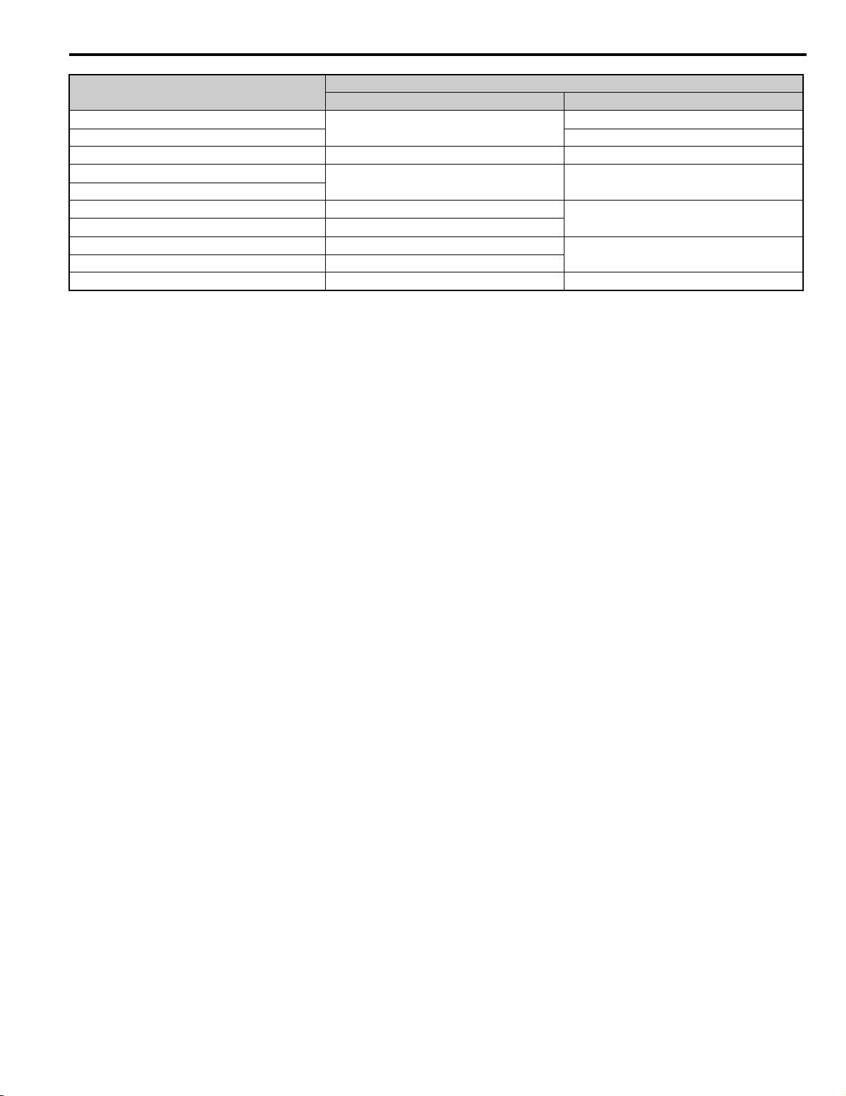
Table i.1 Model Selection
Drive Capacity or Motor Capacity (HP)
≤ 5 2A03P5 4A03P5
7 2A0005 4A0005
10 2A0007 4A0007
15 2A0010 4A0010
20 2A0014 4A0014
25 2A0017 4A0017
30 2A0020 4A0020
40 2A0028 4A0028
50 2A0035 4A0035
200 V Class 400 V Class
Model
14 YASKAWA ELECTRIC TOEP C710656 08B YASKAWA Power Regenerative Unit - R1000 Instruction Manual
Page 15
i.2 General Safety
Drive Capacity or Motor Capacity (HP)
60
74 4A0053
101 2A0073 4A0073
121
148
177 –
215 –
248 –
295 –
422 – 4A0300
200 V Class 400 V Class
2A0053
2A0105 4A0105
Model
4A0043
4A0150
4A0210
■ Installing Standard Configuration Devices
Each regenerative unit requires a corresponding set of input fuses, power coordinating reactor, and current suppression
reactor. Always install the specified devices.
Installation
■
Enclosure Panels
Keep the regenerative unit in a clean environment by installing the regenerative unit in an enclosure panel or selecting an
installation area free of airborne dust, lint, and oil mist. Be sure to leave the required space between regenerative units to
provide for cooling, and take proper measures so the ambient temperature remains within allowable limits and keep
flammable materials away from the regenerative unit. Yaskawa offers protective designs for regenerative units that must
be used in areas subjected to oil mist and excessive vibration. Contact Yaskawa or your Yaskawa agent for details.
Installation Direction
NOTICE: Install the regenerative unit upright as specified in the manual. Refer to Mechanical Installation on page 23 for more
information on installation. Failure to comply may damage the regenerative unit due to improper cooling
■ General Handling
Wiring Check
NOTICE: Do not connect power supply lines to output terminals. Failure to comply will destroy the regenerative unit. Be sure to perform
a final check of all sequence wiring and other connections before turning on the power and also check for short circuits on the control
terminals, which may damage the regenerative unit.
Inspection and Maintenance
WARNING! Electrical Shock Hazard. Capacitors in the regenerative unit do not immediately discharge after shutting off the power. Wait
for at least the amount of time specified on the regenerative unit before touching any components after shutting off the power. Failure to
comply may cause injury to personnel from electrical shock.
WARNING! Burn Hazard. Because the heatsink can get very hot during operation, take proper precautions to prevent burns. When
replacing the cooling fan, shut off the power and wait at least 15 minutes to be sure that the heatsink has cooled down. Failure to
comply may cause burn injury to personnel.
To connect or perform maintenance for the standard configuration devices, turn off the power supply to the regenerative
unit, wait for the time that is given on the regenerative unit, and then confirm that the temperature of the reactor has
sufficiently decreased before you proceed.
Wiring
Yaskawa recommends using ring terminals on all models. Regenerative units require the use of ring terminals for UL/cUL
compliance. Use only the tools recommended by the terminal manufacturer for crimping.
Transporting and Installing the Regenerative Unit
NOTICE: Never steam clean the regenerative unit. During transport, keep the regenerative unit from coming into contact with salts,
fluorine, bromine, phthalate ester, and other such harmful chemicals.
CAUTION! Crush Hazard. Carry all standard configuration and peripheral devices in a method suitable for the weight of the device.
Incorrectly handling devices could cause them to fall and result in injury or damage to the device.
Always use a three-phase power supply. The regenerative unit cannot be used with a single-phase power supply.
YASKAWA ELECTRIC TOEP C710656 08B YASKAWA Power Regenerative Unit - R1000 Instruction Manual 15
Page 16
i.2 General Safety
YAI
◆ Precautions on Using Peripheral Devices
■ Installing a Noise Filter
Install a reactor-type noise filter without a capacitor such as a zero phase reactor after the MCCB on the power supply
side when installing a noise filter on the power supply.
NOTICE: Do not install a filter with a built-in capacitor. The harmonic components may cause the capacitor to overheat or may damage
the capacitor. Always install the specified harmonic noise filter.
Wire Gauges and Wiring Distances
Use a motor cable gauge large enough to avoid unstable regenerative unit phase control from voltage drop caused by a
long motor cable.
When using the digital operator remotely, always use the cable specified (option). When controlling the regenerative unit
remotely using analog signals, limit the length of the control lines between the control signals and regenerative unit to 50
m or shorter and separate the control lines from power lines (main circuit and sequence circuits) to prevent induction from
peripheral devices.
When using a multi-function analog input, connect the shield wire to the sheath ground terminal E (G) with shielded
twisted-pair wires. Refer to Standard Connection Diagram on page 38 for details.
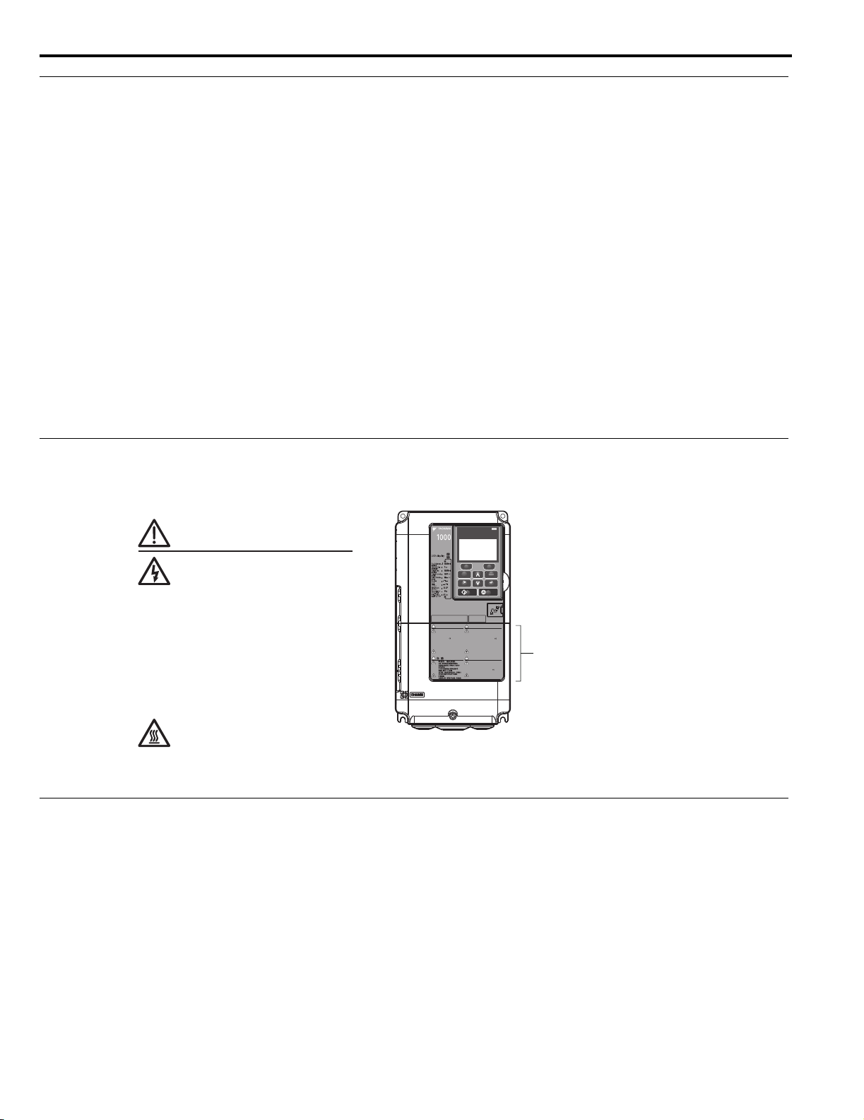
◆ Warning Label Example
Always heed the warning information in the position shown in Figure i.1.
Figure i.1
DIGITAL OPERATOR JVOP-180
ESC
RUN STOP
AVERTISSMENT
Risque de décharge électrique.
●
Lire le manuel avant l'installation.
●
Attendre 5 minutes après la coupure
de l'alimentation, pour permettre
la décharge des condensateurs.
●
Pour répondre aux exigences , s
assurer que le neutre soit relié
à la terre, pour la série 400V.
●
Après avoir déconnécte la protection
entre le driver et le moteur, veuillez
patienter 5 minutes avain d’effectuer
une opération de montage ou de
câblage du variateur.
Surfaces Chaudes
●
Dessus et cotés du boitier Peuvent
devenir chaud. Ne Pas toucher.
危 険
けが.感電のおそれがあります。
●
据え付け、運転の前には必ず取扱説明書を読むこと。
●
通電中および電源遮断後5分以内はフロントカバー
を外さない事。
●
400V級インバータの場合は、電源の中性点が接地
されていることを確認すること。(対応)
●
保守・点検、配線を行う場合は、出力側開閉器を
遮断後5分待って実施してください。
高温注意
●
インバータ上部、両側面は高温になります。
触らないでください。
ALM
F2F1
LO
RE
ENTERRESET
NPJT31470-1
Warning Label
WARNING
Risk of electric shock.
●
Read manual before installing.
●
Wait 5 minutes for capacitor
discharge after disconnecting
power supply.
●
To conform to CE requirements,
make sure to ground the supply
neutral for 400V class.
●
After disconnecting from power
supply, please wait 5 minutes
4
CIMR-AA2A0021FAA
200V 3Phase 5.5kW/3.7kW
S/N:
WARNING
Risk of electric shock.
●
Read manual before installing.
●
Wait 5 minutes for capacitor
discharge after disconnecting
power supply.
●
To conform to requirements,
make sure to ground the supply
neutral for 400V class.
●
After opening the manual switch
between the drive and motor,
please wait 5 minutes before
inspecting, performing
maintenance or wiring the drive.
Hot surfaces
●
Top and Side surfaces may
become hot. Do not touch.
●
●
●
●
before inspecting, performing
maintenance or wiring the
converter.
Hot Surfaces
●
Top and side surfaces may
become hot. Do not touch.
Figure i.1 Warning Information Position
◆ Warranty Information
■ Restrictions
The regenerative unit is not designed or manufactured for use in devices or systems that may directly affect or threaten
human lives or health.
Customers who intend to use the product described in this manual for devices or systems relating to transportation, health
care, space aviation, atomic power, electric power, or in underwater applications must first contact their Yaskawa
representatives or the nearest Yaskawa sales office.
WARNING! Injury to Personnel. This product has been manufactured under strict quality-control guidelines. However, if this product is
to be installed in any location where failure of this product could involve or result in a life-and-death situation or loss of human life or in
a facility where failure may cause a serious accident or physical injury, safety devices must be installed to minimize the likelihood of any
accident.
16 YASKAWA ELECTRIC TOEP C710656 08B YASKAWA Power Regenerative Unit - R1000 Instruction Manual
Page 17

1
Receiving
This chapter explains how to inspect the regenerative unit upon receipt, and gives an overview of
the different enclosure types and components.
1.1 SECTION SAFETY . . . . . . . . . . . . . . . . . . . . . . . . . . . . . . . . . . . . . . . . . . . . . . . . . 18
1.2 MODEL NUMBERS AND NAMEPLATES. . . . . . . . . . . . . . . . . . . . . . . . . . . . . . . . 19
1.3 REGENERATIVE UNIT MODELS AND ENCLOSURE TYPES . . . . . . . . . . . . . . .21
YASKAWA ELECTRIC TOEP C710656 08B YASKAWA Power Regenerative Unit - R1000 Instruction Manual 17
Page 18

1.1 Section Safety
CAUTION
NOTICE
1.1 Section Safety
Do not carry the unit by the front cover or the terminal cover.
Failure to comply may cause the main body of the regenerative unit to fall, resulting in minor or moderate injury.
Observe proper electrostatic discharge procedures (ESD) when handling the regenerative unit and circuit
boards.
Failure to comply may result in ESD damage to circuitry.
18 YASKAWA ELECTRIC TOEP C710656 08B YASKAWA Power Regenerative Unit - R1000 Instruction Manual
Page 19

1.2 Model Numbers and Nameplates
Receiving
1
D1000
Model
Rated output capacity
<1>
PASS
VAJ123456
CIMR-RU2A0073AAA
MODEL
C/C
Regenerative Capacity : 73kW
REV : A
INPUT
OUTPUT
MASS
O / N
S / N
YASKAWA ELECTRIC CORPORATION
MADE IN JAPAN
2-1 Kurosaki-shiroishi, Yahatanishi-Ku, Kitakyushu 806-0004 Japan
209A 1min 25%ED
167A 80% CONT.
253A 1min 25%ED
226A 80% CONT.
: AC3PH 200-240V
50/60Hz
:
:
CIMR-RU2A0073AAA
: DC270-340V
: 6W3050-2-100
: J0073D207410100
: 62kg
PRG : 1010 FILE: NO.E131457
IP00
Software version
Output specifications
Input specifications
MASS
Lot number
Serial number
YAI
1.2 Model Numbers and Nameplates
Perform the following tasks after receiving the regenerative unit:
• Inspect the regenerative unit for damage. If the regenerative unit appear damaged upon receipt, contact the shipper
immediately.
• Verify receipt of the correct model by checking the information on the nameplate.
• If you have received the wrong model or the regenerative unit does not function properly, contact your supplier.
◆ Nameplate
<1> The address of the head office of Yaskawa Electric Corporation (responsible for product liability) is shown on the nameplate.
Figure 1.1 Regenerative Unit Nameplate Information Example
YASKAWA ELECTRIC TOEP C710656 08B YASKAWA Power Regenerative Unit - R1000 Instruction Manual 19
Page 20

1.2 Model Numbers and Nameplates
<1>
CIMR- R A 2 A 0005 A A A
YASKAWA
Power
Regenerative
Unit
No.
Region Code
A
B
C
D
T
U
Japan
China
Europe
India
Asia
USA
No. Voltage Class
4
3-phase, 380-480 Vac
2
3-phase, 200-240 Vac
No.
Customized
Specifications
A
Standard model
No. Enclosure Type
A
No.
Environmental Specification
A
K
M
N
S
Standard
Gas-resistant
Humidity- and dust-resistant
Oil-resistant
Vibration-resistant
R1000
Series
Design
Revision
Order
IP00/Open Type
B
IP20/NEMA Type 1
D1000
◆ Model Numbers
Three-Phase 200 V Class Three-Phase 400 V Class
Model
03P5 5 03P5 5
0005 7 0005 7
0007 9 0007 9
0010 13 0010 13
0014 19 0014 19
0017 23 0017 23
0020 27 0020 27
0028 38 0028 38
0035 47 0035 47
0053 71
0073 98 0053 71
0105 141 0073 98
Rated Output Capacity
(HP)
Model
Rated Output Capacity
(HP)
0043 58
0105 141
0150 201
0210 282
0300 402
<1> Regenerative units with these specifications do not guarantee complete protection for the environmental conditions indicated.
20 YASKAWA ELECTRIC TOEP C710656 08B YASKAWA Power Regenerative Unit - R1000 Instruction Manual
Page 21

1.3 Regenerative Unit Models and Enclosure Types
Receiving
1
1.3 Regenerative Unit Models and Enclosure Types
Two types of enclosures are offered for R1000 regenerative units:
• IP00/Open Type enclosure models are designed for installation in an enclosure panel that serves to protect personnel
from injury caused by accidentally touching live parts.
• IP20/NEMA Type 1 enclosure models mount to an indoor wall or in an enclosure panel. Removing the top protective
cover from a IP20/NEMA Type 1 enclosure drive voids NEMA Type 1 protection while retaining IP20 conformity.
Table 1.1 describes regenerative unit enclosures and models.
Table 1.1 Models and Enclosure Types
Voltage Class
Three-Phase
200 V Class
Three-Phase
400 V Class
Enclosure Type
IP20/NEMA Type 1 IP00/Open Type
2A03P5 2A0035
2A0005 2A0053
2A0007 2A0073
2A0010 2A0105
2A0014 –
2A0017 –
2A0020 –
2A0028 –
4A03P5 4A0035
4A0005 4A0043
4A0007 4A0053
4A0010 4A0073
4A0014 4A0105
4A0017 4A0150
4A0020 4A0210
4A0028 4A0300
YASKAWA ELECTRIC TOEP C710656 08B YASKAWA Power Regenerative Unit - R1000 Instruction Manual 21
Page 22

1.3 Regenerative Unit Models and Enclosure Types
22 YASKAWA ELECTRIC TOEP C710656 08B YASKAWA Power Regenerative Unit - R1000 Instruction Manual
Page 23

2
Mechanical Installation
This chapter explains how to properly mount and install the regenerative unit.
2.1 SECTION SAFETY . . . . . . . . . . . . . . . . . . . . . . . . . . . . . . . . . . . . . . . . . . . . . . . . . 24
2.2 MECHANICAL INSTALLATION . . . . . . . . . . . . . . . . . . . . . . . . . . . . . . . . . . . . . . . 25
YASKAWA ELECTRIC TOEP C710656 08B YASKAWA Power Regenerative Unit - R1000 Instruction Manual 23
Page 24
2.1 Section Safety
W ARNING
CAUTION
2.1 Section Safety
Fire Hazard
Ensure proper cooling when installing an IP00/IP20 regenerative unit in a closed panel or cabinet.
Ensure the air temperature entering the regenerative unit is 50
conditioner. Failure to comply could result in overheating and fire.
Crush Hazard
Only allow qualified personnel to operate a crane or hoist to transport the unit.
Failure to comply may result in serious injury or death from falling equipment.
Use a dedicated lifter when transporting the unit by a lifter.
Failure to comply may result in serious injury or death from falling equipment.
Only use vertical suspension to temporarily lift the unit during installation to an enclosure panel.
Do not use vertical suspension to transport the unit.
Failure to comply may result in serious injury or death from falling equipment.
°C (122°F) or cooler by use of a cooling fan or air
Use screws to securely affix the unit front cover, terminal blocks, and other unit components prior to vertical
suspension.
Failure to comply may result in serious injury or death from falling equipment.
2
Do not subject the unit to vibration or impact greater than 1.96 m/s
Failure to comply may result in serious injury or death from falling equipment.
Do not attempt to flip the unit over or leave the unit unattended while it is suspended by the wires.
Failure to comply may result in serious injury or death from falling equipment.
(0.2 G) while it is suspended by the cables.
Crush Hazard
Do not carry the unit by the front cover or the terminal cover.
Failure to comply may result in minor or moderate injury from the main body of the unit falling.
24 YASKAWA ELECTRIC TOEP C710656 08B YASKAWA Power Regenerative Unit - R1000 Instruction Manual
Page 25
2.2 Mechanical Installation
Mechanical Installation
2
2.2 Mechanical Installation
This section outlines specifications, procedures, and the environment for proper mechanical installation of the
regenerative unit.
◆ Installation Environment
Install the regenerative unit in an environment matching the specifications in Tab le 2 .1 to help prolong the optimum
performance life of the regenerative unit.
Table 2.1 Installation Environment
Environment Conditions
Installation Area Indoors
IP00/Open Type enclosure: -10°C to +50°C (14°F to 122°F)
IP20/NEMA Type 1 enclosure: -10°C to +40°C (14°F to 104°F)
Ambient
Temperature
Humidity 95% RH or less and free of condensation
Storage
Temperature
Surrounding Area
Altitude 1000 m (3281 ft) or lower, up to 3000 m (9843 ft) with derating. Refer to Derating Data on page 151 for details.
Vibration
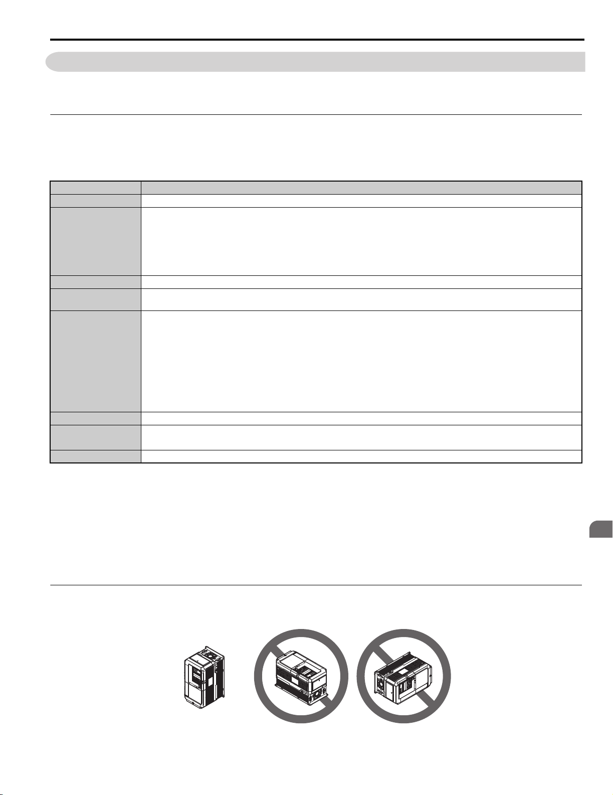
Orientation Install the regenerative unit vertically to maintain maximum cooling effects.
Regenerative unit reliability improves in environments without wide temperature fluctuations.
When using the regenerative unit in an enclosure panel, install a cooling fan or air conditioner in the area to ensure that
the air temperature inside the enclosure does not exceed the specified levels.
Do not allow ice to develop on the regenerative unit.
-20°C to +60°C (-4°F to +140°F)
Install the regenerative unit in an area free from:
• oil mist and dust
• metal shavings, oil, water, or other foreign materials
• radioactive materials
• combustible materials (e.g., wood)
• harmful gases and liquids
• excessive vibration
• chlorides
• direct sunlight.
10 to 20 Hz at 9.8 m/s
10 to 20 Hz at 9.8 m/s
2
, 20 to 55 Hz at 5.9 m/s2 (2A03P5 to 2A0053, 4A03P5 to 4A0073)
2
, 20 to 55 Hz at 2.0 m/s2 (2A0073 to 2A0105, 4A0105 to 4A0300)
WARNING! Fire Hazard. When installing an IP00/IP20 regenerative unit in a closed panel or cabinet, sufficiently cool the panel or
cabinet with a cooling fan or air conditioner so that the air temperature entering the regenerative unit is 50 °C (122 °F) or cooler. Failure
to comply could result in overheating and fire.
NOTICE: Avoid placing regenerative unit peripheral devices, transformers, or other electronics near the regenerative unit as the noise
created can lead to erroneous operation. If such devices must be used in close proximity to the regenerative unit, take proper steps to
shield the regenerative unit from noise.
NOTICE: Prevent foreign matter such as metal shavings and wire clippings from falling into the regenerative unit during installation.
Failure to comply could result in damage to the regenerative unit. Place a temporary cover over the top of the regenerative unit during
installation. Remove the temporary cover before regenerative unit start-up, as the cover will reduce ventilation and cause the
regenerative unit to overheat.
◆ Installation Orientation and Spacing
Install the regenerative unit upright as illustrated in Figure 2.1 to maintain proper cooling.
Figure2.1
Figure 2.1 Correct Installation Orientation
YASKAWA ELECTRIC TOEP C710656 08B YASKAWA Power Regenerative Unit - R1000 Instruction Manual 25
Page 26

2.2 Mechanical Installation
Side Clearance Top/Bottom Clearance
A
A
C
C
BB
D
D
YAI
■ Single Regenerative Unit Installation
Figure 2.2 shows the installation distance required to maintain sufficient space for airflow and wiring. Install the heatsink
against a closed surface to avoid diverting cooling air around the heatsink.
Figure 2.2
A – 50 mm minimum C – 120 mm minimum
B – 30 mm minimum D – Airflow direction
Figure 2.2 Correct Installation Spacing (Single)
■ Parallel Mounting with Drive
When installing the regenerative unit beside a drive, mount the devices according to Figure 2.3.
Figure 2.3
Side Clearance
Figure 2.3 Space Between Regenerative Unit and Drive (Parallel Mounting)
Line up the tops of the drive and regenerative unit.
A A
B
A A
C
DriveRegenerative Unit
B
A – 50 mm minimum C – 60 mm minimum
B – 30 mm minimum D – 120 mm minimum
Top/Bottom Clearance
D
D
26 YASKAWA ELECTRIC TOEP C710656 08B YASKAWA Power Regenerative Unit - R1000 Instruction Manual
Page 27

2.2 Mechanical Installation
Mechanical Installation
2
A
A
A
A
B
C
B
D
D
Line up the tops of the drive and regenerative unit.
Side Clearance Top/Bottom Clearance
Drive
Regenerative
Unit
YAI
■ Side-by-Side Installation with Drive
Models 2A03P5 to 2A0028, 4A03P5 to 4A0028 can take advantage of Side-by-Side installation.
When installing the regenerative unit beside a drive, mount the devices according to Figure 2.4 and set L8-35,
Installation Method Selection, to 1 (Side-by-Side Mounting).
When mounting regenerative units with the minimum clearance of 2 mm according to Figure 2.5, set parameter L8-35 to
1 while considering derating. Refer to Parameter Tables on page 155 for details.
Figure2.4
Note: Align the tops of the regenerative unit and the drives when installing the regenerative unit and the drives of different heights in the
same enclosure panel. Leave space between the tops and bottoms of stacked regenerative unit and drives for easier cooling fan
replacement.
■ Installation Screws
Refer to Exterior and Mounting Dimensions on page 30 for the sizes of the installation screws.
◆ Precautions and Instructions for Installation
Read the following precautions and instructions before installing models 2A0073, 2A0105, and 4A0210 to 4A0300.
WARNING! Crush Hazard. Observe the following instructions and precautions. Failure to comply could result in serious injury or death
from falling equipment.
• Only use vertical suspension to temporarily lift the regenerative unit during installation to an enclosure
panel.
• Do not use vertical suspension to transport the regenerative unit.
• Use screws to securely affix the regenerative unit front cover, terminal blocks, and other regenerative
unit components prior to vertical suspension.
• Do not subject the regenerative unit to vibration or impact greater than 1.96 m/s2 (0.2 G) while it is
suspended by the wires.
• Do not attempt to flip the regenerative unit over while it is suspended by the wires.
• Do not leave the regenerative unit unattended while it is suspended by the wires.
A – 50 mm minimum C – 2 mm minimum
B – 30 mm minimum D – 120 mm minimum
Figure 2.4 Space Between Regenerative Unit and Drive (Side-by-Side)
YASKAWA ELECTRIC TOEP C710656 08B YASKAWA Power Regenerative Unit - R1000 Instruction Manual 27
Page 28

2.2 Mechanical Installation
B
A
C
D
■ Horizontal Suspension of Models 2A0073, 2A0105, and 4A0105 to 4A0300
To make a wire hanger or frame for use when lifting the regenerative unit with a crane, lay the regenerative unit in a
horizontal position and pass a wire through the holes of the four eye bolts.
NOTICE: Damage to Equipment. When lifting the regenerative unit, confirm that the spring washer is fully closed. Failure to comply
may deform or damage the regenerative unit when lifted.
Figure 2.5
A – No space between regenerative
unit and washer
C – Space between regenerative
unit and washer
B – Spring washer: Fully closed D – Spring washer: Open
Figure 2.5 Details of Spring Washers
■ Vertical Suspension of Models 2A0073, 2A0105, and 4A0105 to 4A0300
When vertical suspension of the regenerative unit is required in an enclosure panel, the orientation of the eye bolts for
these regenerative unit models can be easily changed by turning the eye bolts counterclockwise 90 degrees.
Figure 2.6
Figure 2.6 Adjusting Angle of Eye Bolts
1. Gradually take up the slack in the wires and hoist the regenerative unit after the wires are stretched tight.
2. Lower the regenerative unit when ready to install in the enclosure panel. Stop lowering the regenerative unit
when it is near the floor then begin lowering the regenerative unit again very slowly until the regenerative unit is
placed correctly.
28 YASKAWA ELECTRIC TOEP C710656 08B YASKAWA Power Regenerative Unit - R1000 Instruction Manual
Page 29

2.2 Mechanical Installation
Mechanical Installation
2
S /N : J007XE273710001
Operator
Communication Cable Connector
Communication
Cable Connector
Regenerative Unit
D1000
S /N : J007XE273710001
90
78
60
7. 9
minimum
50
Unit: m m
12. 2
1. 6
Inst allat ion holes ( 2-M 3 sc rews , depth 5)
44
15
<1>
YAI
◆ Digital Operator Remote Usage
■ Remote Operation
The digital operator mounted on the regenerative unit can be removed and connected to the regenerative unit using an
extension cable up to 3 m long to facilitate operation when the regenerative unit is installed in a location where it can not
be easily accessed.
The digital operator can also be permanently mounted in remote locations such as panel doors using an extension cable
and an installation support set (depending on the installation type).
■
<1> If you install the digital operator in a control panel or other enclosure, use the optional connection cable.
Digital Operator Dimensions
Figure 2.7 Digital Operator Dimensions
YASKAWA ELECTRIC TOEP C710656 08B YASKAWA Power Regenerative Unit - R1000 Instruction Manual 29
Page 30
2.2 Mechanical Installation
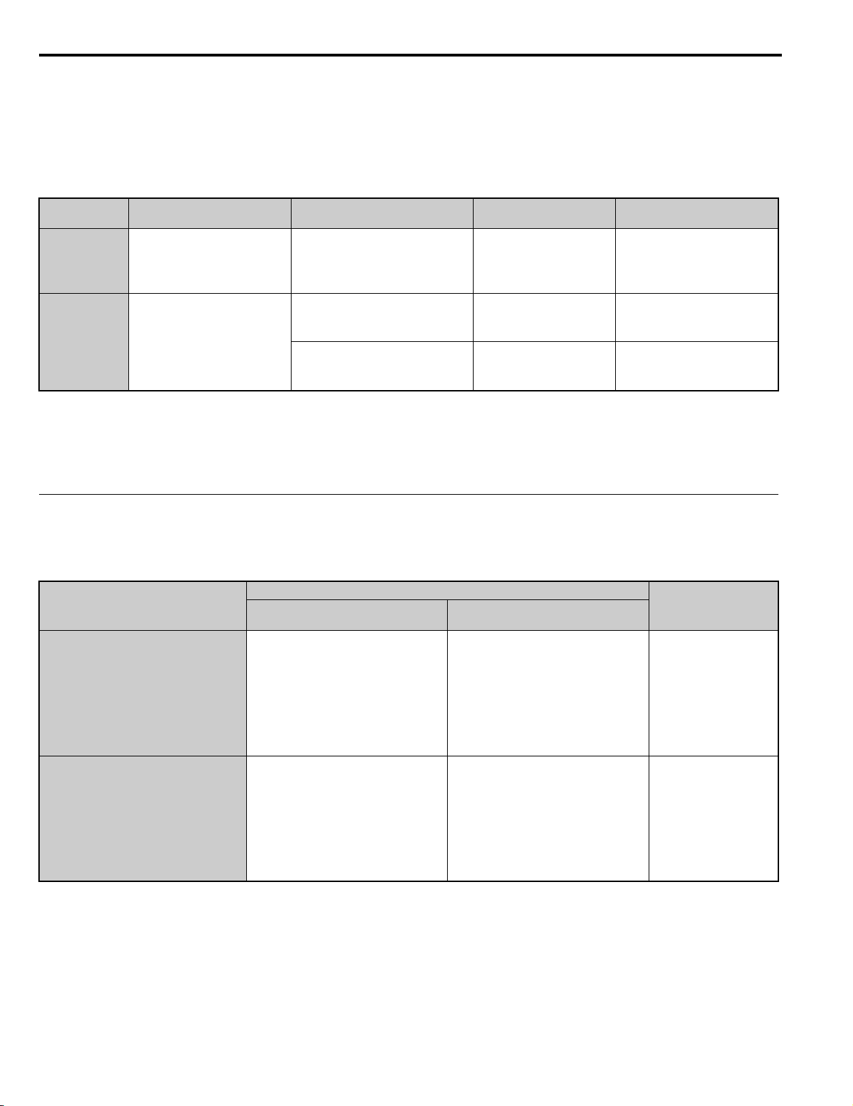
■ Installation Types and Required Materials
The digital operator mounts to an enclosure two different ways:
• External/face-mount installs the operator outside the enclosure panel
• Internal/flush-mount installs the operator inside the enclosure panel
Table 2.2 Digital Operator Installation Methods and Required Tools
Installation
Method
External/
Face-Mount
Internal/
Flush-Mount
<1> If there are welding studs in the control panel, use the Installation Support Set B (for threaded studs).
NOTICE: Prevent foreign matter such as metal shavings or wire clippings from falling into the drive or regenerative unit during
installation and project construction. Failure to comply could result in damage to the drive or regenerative unit. Place a temporary cover
over the top of the drive and regenerative unit during installation. Remove the temporary cover before drive and regenerative unit
start-up, as the cover will reduce ventilation and cause the drive or regenerative unit to overheat.
Description
Simplified installation with the
digital operator is mounted on
the outside of the panel with
two screws.
Encloses the digital operator in
the panel. The front of the
digital operator is flush with
the outside of the panel.
(for mounting with screws through
(for use with threaded studs that are
Installation
Support Sets
––
Installation Support Set A
holes in the panel)
Installation Support Set B
fixed to the panel) <1>
Model Required Tools
Phillips screwdriver
(#1)
EZZ020642A
EZZ020642B
Phillips screwdriver
(#1, #2)
Phillips screwdriver (#1)
Wrench (7 mm)
◆ Exterior and Mounting Dimensions
Use Tab le 2 .3 to find the regenerative unit dimension drawings.
Table 2.3 Models and Types
Protective
Design
IP20/NEMA Type 1 Enclosure
IP00/Open Type Enclosure
Three-Phase
200 V Class
2A03P5
2A0005
2A0007
2A0010
2A0014
2A0017
2A0020
2A0028
2A0035
2A0053
2A0073
2A0105
Regenerative Unit Model
Three-Phase
400 V Class
4A03P5
4A0005
4A0007
4A0010
4A0014
4A0017
4A0020
4A0028
4A0035
4A0043
4A0053
4A0073
4A0105
4A0150
4A0210
4A0300
Page
31
32
30 YASKAWA ELECTRIC TOEP C710656 08B YASKAWA Power Regenerative Unit - R1000 Instruction Manual
Page 31

2.2 Mechanical Installation
Mechanical Installation
2
W1
1.5
H
H1
H0
H2
H3
WD
D1
t1
4-d
Figure 1
YAI
■ IP20/NEMA Type 1 Enclosure Drives
Note: Removing the top protective cover or bottom conduit bracket from an IP20/NEMA Type 1 enclosure drive voids NEMA Type 1
protection while maintaining IP20 conformity.
Model Figure
2A03P5 1
2A0005 1
2A0007 1
2A0010 1
2A0014 1
2A0017 1
2A0020 1
2A0028 1
Table 2.4 Dimensions for IP20/NEMA Type 1 Enclosure: 200 V Class
Dimensions mm (in)
W H D W1 H0 H1 H2 H3 D1 t1 d
140
(5.5)
140
(5.5)
140
(5.5)
180
(7.1)
180
(7.1)
220
(8.7)
220
(8.7)
220
(8.7)
300
(11.8)
300
(11.8)
300
(11.8)
340
(13.4)
340
(13.4)
400
(15.8)
400
(15.8)
400
(15.8)
167
(6.6)
167
(6.6)
167
(6.6)
187
(7.4)
187
(7.4)
197
(7.8)
197
(7.8)
197
(7.8)
122
(4.8)
122
(4.8)
122
(4.8)
160
(6.3)
160
(6.3)
192
(7.6)
192
(7.6)
192
(7.6)
260
(10.2)
260
(10.2)
260
(10.2)
300
(11.8)
300
(11.8)
350
(13.8)
350
(13.8)
350
(13.8)
248
(9.8)6(0.2)40(1.6)55(2.2)5(0.2)
248
(9.8)6(0.2)40(1.6)55(2.2)5(0.2)
248
(9.8)6(0.2)40(1.6)55(2.2)5(0.2)
284
(11.2)8(0.3)40(1.6)75(3.0)5(0.2)
284
(11.2)8(0.3)40(1.6)75(3.0)5(0.2)
335
(13.2)8(0.3)50(2.0)78(3.1)5(0.2)
335
(13.2)8(0.3)50(2.0)78(3.1)5(0.2)
335
(13.2)8(0.3)50(2.0)78(3.1)5(0.2)
M5
M5
M5
M5
M5
M6
M6
M6
Weight
kg (lb)
4
(9)
4
(9)
4
(9)
6
(13)
6
(13)
9
(20)
9
(20)
9
(20)
YASKAWA ELECTRIC TOEP C710656 08B YASKAWA Power Regenerative Unit - R1000 Instruction Manual 31
Page 32

2.2 Mechanical Installation
W1
4-d
H1
H
H2
Max 10
W
t1
t1
D1
D
Figure 1
Max 10
D1
D
t1
H1
H2
H
4-d
W1
W
Max 8Max 8
t1
Figure 2
Table 2.5 Dimensions for IP20/NEMA Type 1 Enclosure: 400 V Class
Model Figure
4A03P5 1
4A0005 1
4A0007 1
4A0010 1
4A0014 1
4A0017 1
4A0020 1
4A0028 1
W H D W1 H0 H1 H2 H3 D1 t1 d
140
(5.5)
140
(5.5)
140
(5.5)
180
(7.1)
180
(7.1)
220
(8.7)
220
(8.7)
220
(8.7)
300
(11.8)
300
(11.8)
300
(11.8)
340
(13.4)
340
(13.4)
400
(15.8)
400
(15.8)
400
(15.8)
167
(6.6)
167
(6.6)
167
(6.6)
187
(7.4)
187
(7.4)
197
(7.8)
197
(7.8)
197
(7.8)
■ IP00/Open Type Enclosure Models
122
(4.8)
122
(4.8)
122
(4.8)
160
(6.3)
160
(6.3)
192
(7.6)
192
(7.6)
192
(7.6)
Dimensions mm (in)
260
(10.2)
260
(10.2)
260
(10.2)
300
(11.8)
300
(11.8)
350
(13.8)
350
(13.8)
350
(13.8)
248
(9.8)6(0.2)40(1.6)55(2.2)5(0.2)
248
(9.8)6(0.2)40(1.6)55(2.2)5(0.2)
248
(9.8)6(0.2)40(1.6)55(2.2)5(0.2)
284
(11.2)8(0.3)40(1.6)75(3.0)5(0.2)
284
(11.2)8(0.3)40(1.6)75(3.0)5(0.2)
335
(13.2)8(0.3)50(2.0)78(3.1)5(0.2)
335
(13.2)8(0.3)50(2.0)78(3.1)5(0.2)
335
(13.2)8(0.3)50(2.0)78(3.1)5(0.2)
M5
M5
M5
M5
M5
M6
M6
M6
Weight
kg (lb)
4
(9)
4
(9)
4
(9)
5
(11)
5
(11)
8
(18)
8
(18)
9
(20)
Table 2.6 Dimensions for IP00/Open Type Enclosure: 200 V Class
Model Figure
2A0035 1
2A0053 1
2A0073 2
2A0105 2
32 YASKAWA ELECTRIC TOEP C710656 08B YASKAWA Power Regenerative Unit - R1000 Instruction Manual
W H D W1 H1 H2 D1 t1 d
275
(10.8)
325
(12.8)
450
(17.7)
500
(19.7)
450
(17.7)
550
(21.7)
705
(27.8)
800
(31.5)
258
(10.2)
283
(11.1)
330
(13.0)
350
(13.8)
Dimensions mm (in)
220
(8.7)
260
(10.2)
325
(12.8)
370
(14.6)
435
(17.1)
535
(21.1)
680
(26.8)
773
(30.4)
7.5
(0.3)
7.5
(0.3)
12.5
(0.5)
13
(0.5)
100
(3.9)
110
(4.3)
130
(5.1)
130
(5.1)
2.3
(0.1)
2.3
(0.1)
3.2
(0.1)
4.5
(0.2)
M6
M6
M10
M12
Weight
kg (lb)
21
(46)
33
(73)
62
(137)
81
(179)
Page 33

2.2 Mechanical Installation
Mechanical Installation
2
Table 2.7 Dimensions for IP00/Open Type Enclosure: 400 V Class
Model Figure
4A0035 1
4A0043 1
4A0053 1
4A0073 1
4A0105 2
4A0150 2
4A0210 2
4A0300 2
Dimensions mm (in)
W H D W1 H1 H2 D1 t1 d
275
(10.8)
275
(10.8)
325
(12.8)
325
(12.8)
450
(17.7)
450
(17.7)
500
(19.7)
500
(19.7)
450
(17.7)
450
(17.7)
550
(21.7)
550
(21.7)
705
(27.8)
705
(27.8)
800
(31.5)
800
(31.5)
258
(10.2)
258
(10.2)
283
(11.1)
283
(11.1)
330
(13.0)
330
(13.0)
350
(13.8)
350
(13.8)
220
(8.7)
220
(8.7)
260
(10.2)
260
(10.2)
325
(12.8)
325
(12.8)
370
(14.6)
370
(14.6)
435
(17.1)
435
(17.1)
535
(21.1)
535
(21.1)
680
(26.8)
680
(26.8)
773
(30.4)
773
(30.4)
7.5
(0.3)
7.5
(0.3)
7.5
(0.3)
7.5
(0.3)
12.5
(0.5)
12.5
(0.5)
13
(0.5)
13
(0.5)
100
(3.9)
100
(3.9)
110
(4.3)
110
(4.3)
130
(5.1)
130
(5.1)
130
(5.1)
130
(5.1)
2.3
(0.1)
2.3
(0.1)
2.3
(0.1)
2.3
(0.1)
3.2
(0.1)
3.2
(0.1)
4.5
(0.2)
4.5
(0.2)
M6
M6
M6
M6
M10
M10
M12
M12
Weight
kg (lb)
20
(44)
20
(44)
33
(73)
33
(73)
62
(137)
62
(137)
86
(190)
87
(192)
YASKAWA ELECTRIC TOEP C710656 08B YASKAWA Power Regenerative Unit - R1000 Instruction Manual 33
Page 34

2.2 Mechanical Installation
34 YASKAWA ELECTRIC TOEP C710656 08B YASKAWA Power Regenerative Unit - R1000 Instruction Manual
Page 35

3
Electrical Installation
This chapter explains proper procedures for wiring the control circuit terminals, motor, and
power supply.
3.1 SECTION SAFETY . . . . . . . . . . . . . . . . . . . . . . . . . . . . . . . . . . . . . . . . . . . . . . . . . 36
3.2 STANDARD CONNECTION DIAGRAM . . . . . . . . . . . . . . . . . . . . . . . . . . . . . . . . .38
3.3 MAIN CIRCUIT CONNECTION DIAGRAM . . . . . . . . . . . . . . . . . . . . . . . . . . . . . . . 40
3.4 TERMINAL BLOCK CONFIGURATION . . . . . . . . . . . . . . . . . . . . . . . . . . . . . . . . . 41
3.5 TERMINAL COVER . . . . . . . . . . . . . . . . . . . . . . . . . . . . . . . . . . . . . . . . . . . . . . . . .45
3.6 DIGITAL OPERATOR AND FRONT COVER . . . . . . . . . . . . . . . . . . . . . . . . . . . . . 47
3.7 TOP PROTECTIVE COVER . . . . . . . . . . . . . . . . . . . . . . . . . . . . . . . . . . . . . . . . . . 49
3.8 MAIN CIRCUIT WIRING . . . . . . . . . . . . . . . . . . . . . . . . . . . . . . . . . . . . . . . . . . . . . 50
3.9 CONTROL CIRCUIT WIRING . . . . . . . . . . . . . . . . . . . . . . . . . . . . . . . . . . . . . . . . . 57
3.10 CONTROL I/O CONNECTIONS . . . . . . . . . . . . . . . . . . . . . . . . . . . . . . . . . . . . . . . 63
3.11 WIRING CHECKLIST. . . . . . . . . . . . . . . . . . . . . . . . . . . . . . . . . . . . . . . . . . . . . . . . 66
YASKAWA ELECTRIC TOEP C710656 08B YASKAWA Power Regenerative Unit - R1000 Instruction Manual 35
Page 36

3.1 Section Safety
DANGER
W ARNING
3.1 Section Safety
Electrical Shock Hazard
Do not connect or disconnect wiring while the power is on.
Failure to comply will result in death or serious injury.
Electrical Shock Hazard
Do not operate equipment with covers removed.
Failure to comply could result in death or serious injury.
The diagrams in this section may show units without covers or safety shields to show details. Be sure to reinstall covers
or shields before operating the unit and run the unit according to the instructions described in this manual.
Always use a type B ground fault circuit interrupter GFCI according to IEC/EN 60755 when a protective
residual current monitor/detection device is installed for indirect or direct shock hazard protection.
The regenerative unit can cause a residual current with a DC component in the protective earthing conductor.
Do not perform work on the unit while wearing loose clothing, jewelry or without eye protection.
Failure to comply could result in death or serious injury.
Remove all metal objects such as watches and rings, secure loose clothing, and wear eye protection before beginning
work on the unit.
Do not remove covers or touch circuit boards while the power is on.
Failure to comply could result in death or serious injury.
Do not allow unqualified personnel to perform work on the unit.
Failure to comply could result in death or serious injury.
Installation, maintenance, inspection, and servicing must be performed only by authorized personnel familiar with
installation, adjustment, and maintenance of this equipment.
Do not touch any terminals before the capacitors have fully discharged.
Failure to comply could result in death or serious injury.
Before wiring terminals, disconnect all power to the equipment. The internal capacitor remains charged even after the
power supply is turned off. After shutting off the power, wait for at least the amount of time specified on the unit before
touching any components.
Fire Hazard
Tighten all terminal screws to the specified tightening torque.
Loose electrical connections could result in death or serious injury by fire due to overheating of electrical connections.
36 YASKAWA ELECTRIC TOEP C710656 08B YASKAWA Power Regenerative Unit - R1000 Instruction Manual
Page 37

3.1 Section Safety
Electrical Installation
3
CAUTION
NOTICE
W ARNING
Do not use improper combustible materials.
Failure to comply could result in death or serious injury by fire.
Do not install the unit to a combustible surface. Never place combustible materials on the unit.
Do not use an improper voltage source.
Failure to comply could result in death or serious injury by fire.
Verify that the rated voltage of the unit matches the voltage of the incoming power supply before applying power.
When installing options, perform all wiring exactly as specified in the wiring diagrams provided.
Failure to do so can result in fire. Improper wiring may damage option components.
Crush Hazard
Do not carry the unit by the front cover or the terminal cover.
Failure to comply may result in minor or moderate injury from the main body of the unit falling.
Observe proper electrostatic discharge procedures (ESD) when handling the unit and circuit boards.
Failure to comply may result in ESD damage to the unit circuitry.
Do not use unshielded cable for control wiring.
Failure to comply may cause electrical interference resulting in poor system performance. Use shielded, twisted-pair
wires and ground the shield to the shield ground terminal E (G) of the unit.
Do not modify the unit circuitry.
Failure to comply could result in damage to the unit and will void warranty.
Yaskawa is not responsible for any modification of the product made by the user. This product must not be modified.
Check all the wiring to ensure that all connections are correct after installing the unit and connecting any other
devices.
Failure to comply could result in damage to the unit.
Check all the wiring to ensure that all connections are correct after installing the regenerative unit and
connecting any other devices.
Failure to comply could result in damage to the regenerative unit.
YASKAWA ELECTRIC TOEP C710656 08B YASKAWA Power Regenerative Unit - R1000 Instruction Manual 37
Page 38

3.2 Standard Connection Diagram
3.2 Standard Connection Diagram
Connect the regenerative unit and peripheral devices as shown in Figure 3.1. It is possible to set and run the regenerative
unit via the digital operator without connecting digital I/O wiring. This section does not discuss regenerative unit
operation; Refer to Start-Up Programming & Operation on page 67 for instructions on operating the regenerative unit.
Refer to Drive Connection Example on page 77 for connection with a drive.
WARNING! Sudden Movement Hazard. Ensure start/stop and safety circuits are wired properly and in the correct state before
energizing the regenerative unit. Failure to comply could result in death or serious injury from moving equipment.
NOTICE: If unsuitable wiring is performed, the regenerative unit could be damaged. Implement protection for branches and
short-circuits according to all national and local standards.
NOTICE: Do not connect AC control circuit ground to regenerative unit enclosure. Improper grounding can cause control circuit
malfunction.
NOTICE: The minimum load for the relay outputs M1-M2, M3-M4, M5-M6 and MA-MB-MC is 10 mA.
NOTICE: When installing a noise filter on the regenerative unit power supply, use a reactor-type noise filter (without a capacitor), such
as a zero phase reactor, and install it after the MCCB on the power supply side. Do not install a filter with a built-in capacitor as the
harmonic components may cause the capacitor to overheat or may damage the capacitor.
NOTICE: When installing a breaker or contactor on the regenerative unit side for an emergency shutoff, confirm that the CHARGE
indicators on the drive and regenerative unit are not lit before closing the breaker or contactor on the regenerative unit output (DC) side.
If the power supply is turned on while there is a voltage charge, an overcurrent will flow and the device may be damaged. Always
confirm that the breaker or contactor on the regenerative unit output (DC) side is turned on before applying power to the regenerative
unit.
38 YASKAWA ELECTRIC TOEP C710656 08B YASKAWA Power Regenerative Unit - R1000 Instruction Manual
Page 39

Electrical Installation
3
Power
Coordinating
Reactor
<1>
Current
Suppression
Reactor
<1>
Fuse
<1>
+
-
IM
+
1
R/L1
S/L2
T/L3
-
Drive
Regenerative Unit
U/T1
V/T2
W/T3
Motor
R1000
E(G)
Shield ground
terminal
Forced operation
command
Automatic operation
command
External fault
Fault reset
(Reserved)
(Reserved)
(Reserved)
External Baseblock
Multi-function
digital inputs
(default setting)
ThreePhase
Power
Supply
GFCI
or
MCCB
<4>
<4>
CN5-A
CN5-B
CN5-C
Option card
connectors
MEMOBUS/
Modbus Communication
RS-422/RS-485
max. 115.2 kbps
Termination resistor
(120 Ω, 1/2 W)
DIP
Switch S2
R+
R-
S+
S-
IG
(Reserved)
(Reserved)
(Reserved)
<2>
<5>
<5>
<3>
<5>
S1
S2
S3
S4
S5
S6
S7
S8
Control
Circuit
Ground
U
V
W
X
Y
Z
X
Y
Z
R
S
T
DIP Switch S1
shielded line
main circuit terminal
twisted-pair shielded line
control circuit terminal
FM
AC
0V
E (G)
AM
Multi-function analog output 1
(Power Supply Side Power)
-10 to +10 Vdc (2 mA) or
4 to 20 mA
Multi-function analog output 2
(Power Supply Side Current)
-10 to +10 Vdc (2 mA) or
4 to 20 mA
AM
FM
<7>
<7>
+
+
-
VI
+V
A1
A2
A3
AC
-V
Power supply
+10.5 Vdc, max. 20 mA
Power supply, -10.5 Vdc,
max. 20 mA
Analog Input 1
Analog Input 2
Analog Input 3
R/L1
S/L2
T/L3
r1/ 11
1/
21
t1/
31
Ground
MA
MB
MC
Fault relay output
250 Vac, max. 1 A
30 Vdc, max. 1 A
(min. 5 Vdc, 10 mA)
Multi-function relay output
(Operation Ready)
250 Vac, max. 1 A
30 Vdc, max. 1 A
(min. 5 Vdc, 10 mA)
Multi-function relay
output (During Run 1)
250 Vac, max. 1 A
30 Vdc, max. 1 A
(min. 5 Vdc, 10 mA)
Multi-function relay
output (During MC on)
<3>
250 Vac, max. 1 A
30 Vdc, max. 1 A
(min. 5 Vdc, 10 mA)
M1
M2
M3
M4
M5
M6
Sink
SC
+24 V
Sink / Source mode
selection wire link
(default: Sink)
SP
SN
<6>
YAI
3.2 Standard Connection Diagram
Figure3.1
<1> Use the specified AC reactor and fuse. Non-specified devices may cause erroneous operation.
<2> Always take the power supply for the drive’s AC power supply terminals (R/L1, S/L2, and T/L3) from the secondary side of the
power coordinating reactor.
<3> Always take the power supply for the unit’s power supply voltage detection inputs (r1/ 11, 1/ 21, and t1/ 31) from the primary
side of the power coordinating reactor.
<4> Do not use a DC bus line that is longer than 5 m (16.4 ft) to connect the regenerative unit and drive.
<5> Do not use a line longer than 10 m (32.8 ft) to connect the power coordinating reactor and the regenerative unit.
<6> This figure shows an example of a sequence input to S1 through S8 using a non-powered relay or an NPN transistor. Install the wire
link between terminals SC-SP for Sink mode and SC-SN for Source mode. Leave it out for external power supply. Never short
terminals SP and SN as doing so will damage the regenerative unit.
<7> Multi-function analog outputs work with devices such as analog frequency meters, ammeters, voltmeters, and wattmeters. They are
not intended for use as a feedback-type signal.
Figure 3.1 Standard Connection Diagram (example: model 2A0007)
YASKAWA ELECTRIC TOEP C710656 08B YASKAWA Power Regenerative Unit - R1000 Instruction Manual 39
Page 40

3.3 Main Circuit Connection Diagram
–
Relay
DC
Fuse
Gate
board
Control
board
Operator
+
+
Current
sensor
R/L1
S/L2
T/L3
r1/ 11
1/ 21
t1/ 31
YAI
YAI
3.3 Main Circuit Connection Diagram
Refer to diagrams in this section when wiring the main circuit of the regenerative unit. Connections may vary based on
regenerative unit capacity. The DC power supply for the main circuit also provides power to the control circuit.
NOTICE: Do not use the negative DC bus terminal “ ” as a ground terminal. This terminal is at high DC voltage potential. Improper
–
wiring connections could damage the regenerative unit.
◆ 2A03P5 to 2A0053, and 4A03P5 to 4A0073
Figure 3.2
Figure 3.2 Connecting Main Circuit Terminals
◆ 2A0073 to 2A0105, and 4A0105 to 4A0300
Figure 3.3
+
+
Gate
board
Relay
24 V
Power
Supply
DC
Fuse
–
R/L1
S/L2
T/L3
r1/ 11
1/ 21
t1/ 31
Current
sensor
Operator
Control
board
Figure 3.3 Connecting Main Circuit Terminals
40 YASKAWA ELECTRIC TOEP C710656 08B YASKAWA Power Regenerative Unit - R1000 Instruction Manual
Page 41

3.4 Terminal Block Configuration
Electrical Installation
3
3.4 Terminal Block Configuration
Refer to the terminal block configuration diagrams in Tab le 3 .1 for the location of the main circuit terminal block.
Table 3.1 Terminal Block Configuration
Model Figure
2A03P5 Figure 3.4
2A0005 Figure 3.4
2A0007 Figure 3.4
2A0010 Figure 3.5
2A0014 Figure 3.5
200 V Class
Models
400 V Class
Models
2A0017 Figure 3.6
2A0020 Figure 3.6
2A0028 Figure 3.6
2A0035 Figure 3.7
2A0053 Figure 3.8
2A0073 Figure 3.10
2A0105 Figure 3.11
4A03P5 Figure 3.4
4A0005 Figure 3.4
4A0007 Figure 3.4
4A0010 Figure 3.5
4A0014 Figure 3.5
4A0017 Figure 3.6
4A0020 Figure 3.6
4A0028 Figure 3.6
4A0035 Figure 3.7
4A0043 Figure 3.7
4A0053 Figure 3.9
4A0073 Figure 3.9
4A0105 Figure 3.10
4A0150 Figure 3.10
4A0210 Figure 3.11
4A0300 Figure 3.11
YASKAWA ELECTRIC TOEP C710656 08B YASKAWA Power Regenerative Unit - R1000 Instruction Manual 41
Page 42

3.4 Terminal Block Configuration
YAI
YAI
Figure 3.4
Figure 3.4 Main Circuit Terminal Block Configuration (Models 2A03P5 to 2A0007, 4A03P5 to 4A0007)
Figure 3.5
Figure 3.5 Main Circuit Terminal Block Configuration (Models 2A0010, 2A0014, 4A0010, 4A0014)
42 YASKAWA ELECTRIC TOEP C710656 08B YASKAWA Power Regenerative Unit - R1000 Instruction Manual
Page 43

Electrical Installation
3
Figure3.6
YAI
RL1 SL1 TL3
D1000
r1/ℓ11 t1/ℓ31 1/ℓ21
r1/ℓ11 t1/ℓ31 1/ℓ21
R1000
Figure3.7
3.4 Terminal Block Configuration
Figure 3.6 Main Circuit Terminal Block Configuration (Models 2A0017 to 2A0028, 4A0017 to 4A0028)
Figure3.8
Figure 3.7 Main Circuit Terminal Block Configuration (Models 2A0035, 4A0035, 4A0043)
Figure 3.8 Main Circuit Terminal Block Configuration (Models 2A0053)
YASKAWA ELECTRIC TOEP C710656 08B YASKAWA Power Regenerative Unit - R1000 Instruction Manual 43
Page 44

3.4 Terminal Block Configuration
r1/ℓ11 t1/ℓ31 1/ℓ21
R/L1
S/L2
T/L3
r1/ℓ11 t1/ℓ31 1/ℓ21
D1000
R/L1
S/L2
T/L3
r1/ℓ11 t1/ℓ31 1/ℓ21
r1/ℓ11 t1/ℓ31 1/ℓ21
D1000
R/L1
S/L2
T/L3
+
-
-
+
D1000
Figure 3.9
Figure 3.9 Main Circuit Terminal Block Configuration (Models 4A0053, 4A0073)
Figure 3.10
Figure 3.11
Figure 3.10 Main Circuit Terminal Block Configuration (Models 2A0073, 4A0105, 4A0150)
r1/ℓ11 t1/ℓ31 1/ℓ21
Figure 3.11 Main Circuit Terminal Block Configuration (Models 2A0105, 4A0210, 4A0300)
44 YASKAWA ELECTRIC TOEP C710656 08B YASKAWA Power Regenerative Unit - R1000 Instruction Manual
Page 45

3.5 Terminal Cover
Electrical Installation
3
YAI
<1>
YAI
3.5 Terminal Cover
Follow the procedure below to remove the terminal cover for wiring and to reattach the terminal cover after wiring is
complete.
◆ Models 2A03P5 to 2A0028, 4A03P5 to 4A0028 (IP20/NEMA Type 1)
■ Removing the Terminal Cover
Loosen the terminal cover screw using a #2 Phillips screwdriver. Screw sizes vary by regenerative unit model.
Then, push in on the tab located on the bottom of the terminal cover and gently pull forward to remove the terminal cover.
Figure3.12
Figure 3.12 Removing the Terminal Cover on an IP20/NEMA Type 1 Enclosure Model
■ Reattaching the Terminal Cover
Power lines and signal wiring should pass through the opening provided. Refer to Wiring the Main Circuit Terminal on
page 56 and Wiring the Control Circuit Terminal on page 61 for details on wiring.
Reattach the terminal cover after completing the wiring to the regenerative unit and other devices.
<1> Connect ground wiring first, followed by the main circuit, and then wire the control circuit. Power lines and signal wiring
exit through the opening provided.
Figure 3.13 Reattaching the Terminal Cover on an IP20/NEMA Type 1 Enclosure Model
YASKAWA ELECTRIC TOEP C710656 08B YASKAWA Power Regenerative Unit - R1000 Instruction Manual 45
Page 46

3.5 Terminal Cover
◆ Models 2A0035 to 2A0105, 4A0035 to 4A0300 (IP00/Open Type enclosure)
■ Removing the Terminal Cover
1. Loosen the screws on the terminal cover, then pull forward on the terminal cover to free it from the regenerative
unit.
Note: Models 2A0073, 2A0105, and 4A0105 to 4A0300 have three mounting screws above the terminal cover.
CAUTION! Do not completely remove the cover screws, just loosen them. If the cover screws are removed completely, the terminal
cover may fall off causing an injury.
Larger capacity regenerative units have large and heavy terminal covers. Remove and attach these covers with care.
Figure 3.13
Figure 3.14 Removing the Terminal Cover on an IP00/Open Type enclosure Model
■ Reattaching the Terminal Cover
After wiring the terminal board and other devices, double-check connections and reattach the terminal cover. Refer to
Wiring the Main Circuit Terminal on page 56 and Wiring the Control Circuit Terminal on page 61 for details on
wiring.
<1>
<1> Connect ground wiring first, followed by the main circuit, and then wire the control circuit. Power lines and signal wiring
exit through the opening provided.
Figure 3.15 Reattaching the Terminal Cover on an IP00/Open Type enclosure Model
46 YASKAWA ELECTRIC TOEP C710656 08B YASKAWA Power Regenerative Unit - R1000 Instruction Manual
Page 47

3.6 Digital Operator and Front Cover
Electrical Installation
3
Removing
Reattaching
3.6 Digital Operator and Front Cover
NOTICE: Be sure to remove the digital operator prior to opening or reattaching the front cover. Leaving the digital operator plugged into
the regenerative unit when removing the front cover can result in erroneous operation caused by a poor connection. Firmly fasten the
front cover back into place before reattaching the digital operator.
Detach the digital operator from the regenerative unit for remote operation or when opening the front cover to install an
option card.
◆ Removing/Reattaching the Digital Operator
While pressing on the tab located on the right side of the digital operator, pull the digital operator forward to remove it
from the regenerative unit.
Insert the digital operator into the opening in the top cover while aligning it with the notches on the left side of the
opening. Next, press gently on the right side of the operator until it clicks into place.
Figure3.14
Figure 3.16 Removing/Reattaching the Digital Operator
◆ Removing/Reattaching the Front Cover
■ Removing the Front Cover
Models 2A03P5 to 2A0028, and 4A03P5 to 4A0028
After removing the terminal cover and the digital operator, loosen the screw that affixes the front cover (models 2A03P5
to 2A0007, and 4A03P5 to 4A0007 do not use a screw to affix the front cover). Pinch in on the tabs found on each side of
the front cover, then pull forward to remove it from the regenerative unit.
Figure 3.17 Remove the Front Cover (2A03P5 to 2A0028, 4A03P5 to 4A0028)
YASKAWA ELECTRIC TOEP C710656 08B YASKAWA Power Regenerative Unit - R1000 Instruction Manual 47
Page 48

3.6 Digital Operator and Front Cover
Free hooks on both
sides of the cover
Hook
Hook
Front cover
installation screw
Models 2A0035 to 2A0105, and 4A0035 to 4A0300
Remove the terminal cover and the digital operator.
1.
2. Loosen the installation screw on the front cover.
3. Use a straight-edge screwdriver to loosen the hooks on each side of the cover that hold it in place.
Figure 3.15
Figure 3.18 Remove the Front Cover (2A0035 to 2A0105, and 4A0035 to 4A0300)
4. Unhook the left side of the front cover then swing the left side towards you as shown in Figure 3.16 until the
Figure 3.16
cover comes off.
Figure 3.19 Remove the Front Cover (2A0035 to 2A0105, and 4A0035 to 4A0300)
■ Reattaching the Front Cover
Models 2A03P5 to 2A0028, 4A03P5 to 4A0028
Reverse the instructions given in Models 2A03P5 to 2A0028, 4A03P5 to 4A0028 (IP20/NEMA Type 1) on page 45 to
reattach the front cover. Pinch inwards on the hooks found on each side of the front cover while guiding it back into the
regenerative unit. Make sure it clicks firmly into place.
Models 2A0035 to 2A0105, and 4A0035 to 4A0300
Slide the front cover so the hooks on the top connect to the regenerative unit.
1.
Figure 3.17
Figure 3.20 Reattach the Front Cover (2A0035 to 2A0105, and 4A0035 to 4A0300)
2. After connecting the hooks to the regenerative unit, press firmly on the cover to lock it into place.
48 YASKAWA ELECTRIC TOEP C710656 08B YASKAWA Power Regenerative Unit - R1000 Instruction Manual
Page 49

3.7 Top Protective Cover
Electrical Installation
3
Protective Cover
Mounting Holes
R1000
3.7 Top Protective Cover
Models 2A03P5 to 2A0028, 4A03P5 to 4A0028 are designed to IP20/NEMA Type 1 specifications with a protective
cover on the top. Removing this top protective cover or the bottom conduit bracket from an IP20/NEMA Type 1 enclosure
models voids the NEMA Type 1 protection while maintaining IP20 conformity.
◆ Removing and Reattaching the Top Protective Cover
Insert the tip of a straight-edge screwdriver into the small opening located on the front edge of the top protective cover.
Gently apply pressure as shown in the figure below to free the cover from the regenerative unit. Insert the two small
protruding hooks on the rear side of the top protective cover into the provided mounting holes near the back of the
regenerative unit, then press down on the front side of the top protective cover to fasten the cover into place.
Note: Removing the top protective cover or the bottom conduit bracket from an IP20/NEMA Type 1 enclosure drive voids the NEMA
Figure3.18
Type 1 protection while maintaining IP20 conformity.
Figure 3.21 Removing and Reattaching the Top Protective Cover
YASKAWA ELECTRIC TOEP C710656 08B YASKAWA Power Regenerative Unit - R1000 Instruction Manual 49
Page 50

3.8 Main Circuit Wiring
3
3.8 Main Circuit Wiring
This section describes the functions, specifications, and procedures required to safely and properly wire the main circuit
in the regenerative unit.
NOTICE: Do not switch the regenerative unit input power supply on and off frequently. Frequently switching the unit on and off shortens
the life of the DC bus capacitors, and can cause premature unit failure. For the full performance life, refrain from switching the unit on
and off more than once every 30 minutes.
NOTICE: Do not solder the ends of wire connections to the regenerative unit. Soldered wiring connections can loosen over time.
Improper wiring practices could result in regenerative unit malfunction due to loose terminal connections.
◆ Main Circuit Terminal Functions
Table 3.2 Main Circuit Terminal Functions
Termi nal Type
400 V Class 4A03P5 to 4A0300
Model
R/L1
S/L2
T/L3
r1/ 11
1/ 21
t1/ 31
–
+
2A03P5 to 2A0105
Main circuit power supply input
Power supply voltage detection inputs
DC voltage input These terminals input a DC voltage –
For 200 V class: 100 Ω or less
For 400 V class: 10 Ω or less
These are the power supply input terminals that connect to
the input reactor.
These terminals are to detect the power supply voltage order
and voltage levels.
Grounding terminal 55
Function Page200 V Class
38
38
◆ Protecting Main Circuit Terminals
■ Insulation Caps or Sleeves
Use insulation caps or sleeves when wiring the regenerative unit with crimp terminals. Take particular care to ensure that
the wiring does not touch nearby terminals or the surrounding case.
◆ Wire Gauges and Tightening Torque
Use the tables in this section to select the appropriate wires and crimp terminals.
Note: 1. Wire gauge recommendations based on continuous current ratings using 75°C 600 Vac vinyl-sheathed wire assuming ambient
temperature within 40°C.
2. Use terminals and when connecting the drive to the regenerative unit.
Consider the amount of voltage drop when selecting wire gauges. Increase the wire gauge when the voltage drop is greater than 2% of motor rated
voltage. Ensure the wire gauge is suitable for the terminal block. Use the following formula to calculate the amount of voltage drop:
Line drop voltage (V) =
Refer to UL Standards Compliance on page 207 for information on UL compliance.
The wire gauges listed inTab le 3 .3 and Ta bl e 3. 4 are Yaskawa recommendations. Refer to local codes for proper wire
gauge selections.
+ –
× wire resistance (Ω/km) × wire length (m) × current (A) × 10
-3
50 YASKAWA ELECTRIC TOEP C710656 08B YASKAWA Power Regenerative Unit - R1000 Instruction Manual
Page 51

Electrical Installation
3
■ Three-Phase 200 V Class
+
+
+
+
+
+
Table 3.3 Wire Gauge and Torque Specifications (Three-Phase 200 V Class)
3.8 Main Circuit Wiring
Model Terminal
R/L1,S/L2,T/L3 3.5 3.5 to 14 12 12 to 6 4 4 to 16 M4
–
,
2A03P5
r1/ 11, 1/ 21,t1/ 31
R/L1,S/L2,T/L3 3.5 3.5 to 14 12 12 to 6 4 4 to 16 M4
–
,
2A0005
r1/ 11, 1/ 21,t1/ 31
R/L1,S/L2,T/L3 3.5 3.5 to 14 12 12 to 6 4 4 to 16 M4
–
,
2A0007
r1/ 11, 1/ 21,t1/ 31
R/L1,S/L2,T/L3 5.5 5.5 to 14 10 10 to 6 4 4 to 16 M4
–
,
2A0010
r1/ 11, 1/ 21,t1/ 31
R/L1,S/L2,T/L3 8 8 to 14 8 8 to 6 6 6 to 16 M4
–
,
2A0014
r1/ 11, 1/ 21,t1/ 31
R/L1,S/L2,T/L3 14 14 to 38 8 8 to 1 10 10 to 25 M6
–
,
2A0017
r1/ 11, 1/ 21,t1/ 31
For Asia <1> For U.S.A. <2>
Recomm.
Gauge
mm
2
Applicable
Gauge
2
mm
Recomm.
Gauge
AWG
Applicable
Gauge
AWG
For Europe and China
<3>
Recomm.
Gauge
mm
2
Applicable
Gauge
2
mm
3.5 3.5 to 14 12 12 to 6 4 4 to 16 M4
2 2 14 14 2.5 2.5 M3.5
2 2 to 8 12 12 to 8 4 4 to 10 M5
3.5 3.5 to 14 10 10 to 6 4 4 to 16 M4
2 2 14 14 2.5 2.5 M3.5
2 2 to 8 12 12 to 8 4 4 to 10 M5
3.5 3.5 to 14 10 10 to 6 4 4 to 16 M4
2 2 14 14 2.5 2.5 M3.5
3.5 3.5 to 8 10 10 to 8 4 4 to 10 M5
14 14 6 6 16 16 M4
2 2 14 14 2.5 2.5 M3.5
5.5 5.5 to 14 8 8 to 6 4 4 to 16 M6
14 14 6 6 16 16 M4
2 2 14 14 2.5 2.5 M3.5
5.5 5.5 to 14 8 8 to 6 6 6 to 16 M6
14 14 to 38 4 4 to 1 16 16 to 25 M6
2 2 14 14 2.5 2.5 M3.5
5.5 5.5 to 22 8 8 to 4 10 10 to 25 M6
Screw
Size
Tightening
Tor que
Nxm
(lbxin.)
2.1 to 2.3
(18.6 to 20.4)
2.1 to 2.3
(18.6 to 20.4)
0.8 to 1.0
(7.1 to 8.9)
2.0 to 2.5
(17.7 to 22.1)
2.1 to 2.3
(18.6 to 20.4)
2.1 to 2.3
(18.6 to 20.4)
0.8 to 1.0
(7.1 to 8.9)
2.0 to 2.5
(17.7 to 22.1)
2.1 to 2.3
(18.6 to 20.4)
2.1 to 2.3
(18.6 to 20.4)
0.8 to 1.0
(7.1 to 8.9)
2.0 to 2.5
(17.7 to 22.1)
2.1 to 2.3
(18.6 to 20.4)
2.1 to 2.3
(18.6 to 20.4)
0.8 to 1.0
(7.1 to 8.9)
2.0 to 2.5
(17.7 to 22.1)
2.1 to 2.3
(18.6 to 20.4)
2.1 to 2.3
(18.6 to 20.4)
0.8 to 1.0
(7.1 to 8.9)
2.0 to 2.5
(17.7 to 22.1)
3.6 to 4.0
(31.9 to 35.4)
3.6 to 4.0
(31.9 to 35.4)
0.8 to 1.0
(7.1 to 8.9)
5.4 to 6.0
(47.8 to 53.1)
YASKAWA ELECTRIC TOEP C710656 08B YASKAWA Power Regenerative Unit - R1000 Instruction Manual 51
Page 52

3.8 Main Circuit Wiring
–
+
–
+
–
+
–
+
–
+
–
+
Model Termi nal
R/L1,S/L2,T/L3 14 14 to 38 6 6 to 1 10 10 to 25 M6
,
2A0020
r1/ 11, 1/ 21,t1/ 31
R/L1,S/L2,T/L3 22 22 to 38 4 4 to 1 16 16 to 35 M6
,
2A0028
r1/ 11, 1/ 21,t1/ 31
R/L1,S/L2,T/L3 38 38 to 70 2 2 to 2/0 25 25 to 70 M8
,
2A0035
r1/ 11, 1/ 21,t1/ 31
R/L1,S/L2,T/L3 50 50 to 150 2/0 2/0 to 250 50 50 to 95 M8
2A0053
,
r1/ 11, 1/ 21,t1/ 31
R/L1,S/L2,T/L3 80 80 to 150
,
2A0073
r1/ 11, 1/ 21,t1/ 31
R/L1,S/L2,T/L3 80 × 2P 80 to 325
,
2A0105
r1/ 11, 1/ 21,t1/ 31
For Asia <1> For U.S.A. <2>
Recomm.
Gauge
mm
2
Applicable
Gauge
2
mm
Recomm.
Gauge
AWG
Applicable
Gauge
AWG
For Europe and China
<3>
Recomm.
Gauge
mm
2
Applicable
Gauge
2
mm
22 22 to 38 4 4 to 1 16 16 to 25 M6
2 2 14 14 2.5 2.5 M3.5
8 8 to 22 6 6 to 4 10 10 to 25 M6
30 30 to 38 2 2 to 1 25 25 to 35 M6
2 2 14 14 2.5 2.5 M3.5
14 14 to 22 6 6 to 4 16 16 to 25 M6
38 38 to 70 1/0 1/0 to 2/0 35 35 to 70 M8
2 2 to 5.5 14 14 to 10 2.5 2.5 to 6 M4
22 22 4 4 16 16 to 25 M8
80 80 to 150 4/0 4/0 to 250 70 70 to 95 M8
2 2 to 5.5 14 14 to 10 2.5 2.5 to 6 M4
22 22 to 60 3 3 to 2 25 25 to 35 M10
1/0 to 300 70 70 to 150 M12
3/0 to 300 120 120 to 150 M12
125 125 to 150
1/0
3/0
× 2P
× 2P
2 2 to 5.5 14 14 to 10 2.5 2.5 to 6 M4
60 60 to 150 1/0 1/0 to 300 35 35 to 150 M12
150 × 2P 150 to 325
3/0
300
× 2P
× 2P
3/0 to 600
300 to 600
95 × 2P
150 × 2P
95 to 240 M12
150 to 240 M12
2 2 to 5.5 14 14 to 10 2.5 2.5 to 6 M4
60 60 to 180 1/0 1/0 to 300 70 70 to 240 M12
Screw
Size
Tightening
Torque
Nxm
(lbxin.)
3.6 to 4.0
(31.9 to 35.4)
3.6 to 4.0
(31.9 to 35.4)
0.8 to 1.0
(7.1 to 8.9)
5.4 to 6.0
(47.8 to 53.1)
3.6 to 4.0
(31.9 to 35.4)
3.6 to 4.0
(31.9 to 35.4)
0.8 to 1.0
(7.1 to 8.9)
5.4 to 6.0
(47.8 to 53.1)
5.4 to 6.0
(47.8 to 53.1)
5.4 to 6.0
(47.8 to 53.1)
1.1 to 1.2
(9.7 to 10.6)
9.0 to 11.0
(79.7 to 97.4)
13.5 to 15.0
(119,5 to
132,8)
13.5 to 15.0
(119,5 to
132,8)
1.1 to 1.2
(9.7 to 10.6)
18.0 to 23.0
(159 to 204)
32.0 to 40.0
(283 to 354)
32.0 to 40.0
(283 to 354)
1.1 to 1.2
(9.7 to 10.6)
32.0 to 40.0
(283 to 354)
32.0 to 40.0
(283 to 354)
32.0 to 40.0
(283 to 354)
1.1 to 1.2
(9.7 to 10.6)
32.0 to 40.0
(283 to 354)
<1> Gauges listed here are for use in Japan.
<2> Gauges listed here are for use in the United States.
<3> Gauges listed here are for use in Europe and China.
52 YASKAWA ELECTRIC TOEP C710656 08B YASKAWA Power Regenerative Unit - R1000 Instruction Manual
Page 53

Electrical Installation
3
Table 3.4 Three-Phase 400 V Class
+
+
+
+
+
+
3.8 Main Circuit Wiring
Model Terminal
R/L1,S/L2,T/L3 3.5 3.5 to 14 10 10 to 6 4 4 to 16 M4
–
,
4A03P5
r1/ 11, 1/ 21,t1/ 31
R/L1,S/L2,T/L3 3.5 3.5 to 14 10 10 to 6 4 4 to 16 M4
–
,
4A0005
r1/ 11, 1/ 21,t1/ 31
R/L1,S/L2,T/L3 3.5 3.5 to 14 12 12 to 6 4 4 to 16 M4
–
,
4A0007
r1/ 11, 1/ 21,t1/ 31
R/L1,S/L2,T/L3 3.5 3.5 to 14 12 12 to 6 4 4 to 16 M4
–
,
4A0010
r1/ 11, 1/ 21,t1/ 31
R/L1,S/L2,T/L3 3.5 3.5 to 14 10 10 to 6 4 4 to 16 M4
–
,
4A0014
r1/ 11, 1/ 21,t1/ 31
R/L1,S/L2,T/L3 8 8 to 38 10 10 to 1 10 10 to 25 M6
–
,
4A0017
r1/ 11, 1/ 21,t1/ 31
For Asia <1> For U.S.A. <2>
Recomm.
Gauge
mm
2
Applicable
Gauge
2
mm
Recomm.
Gauge
AWG
Applicable
Gauge
AWG
For Europe and China
<3>
Recomm.
Gauge
mm
2
Applicable
Gauge
2
mm
3.5 3.5 to 14 12 12 to 6 4 4 to 16 M4
2 2 14 14 2.5 2.5 M3.5
2 2 to 8 12 12 to 10 4 4 to 6 M5
3.5 3.5 to 14 12 12 to 6 4 4 to 16 M4
2 2 14 14 2.5 2.5 M3.5
2 2 to 8 12 12 to 10 4 4 to 6 M5
3.5 3.5 to 14 12 12 to 6 4 4 to 16 M4
2 2 14 14 2.5 2.5 M3.5
2 2 to 8 10 10 4 4 to 6 M5
5.5 5.5 to 14 10 10 to 6 6 6 to 16 M4
2 2 14 14 2.5 2.5 M3.5
3.5 3.5 to 14 10 10 to 6 4 4 to 16 M6
5.5 5.5 to 14 10 10 to 6 6 6 to 16 M4
2 2 14 14 2.5 2.5 M3.5
3.5 3.5 to 14 10 10 to 6 4 4 to 16 M6
14 14 to 38 6 6 to 1 16 16 to 25 M6
2 2 14 14 2.5 2.5 M3.5
5.5 5.5 to 22 8 8 to 6 10 10 to 16 M6
Screw
Size
Tightening
Tor que
Nxm
(lbxin.)
2.1 to 2.3
(18.6 to 20.4)
2.1 to 2.3
(18.6 to 20.4)
0.8 to 1.0
(7.1 to 8.9)
2.0 to 2.5
(17.7 to 22.1)
2.1 to 2.3
(18.6 to 20.4)
2.1 to 2.3
(18.6 to 20.4)
0.8 to 1.0
(7.1 to 8.9)
2.0 to 2.5
(17.7 to 22.1)
2.1 to 2.3
(18.6 to 20.4)
2.1 to 2.3
(18.6 to 20.4)
0.8 to 1.0
(7.1 to 8.9)
2.0 to 2.5
(17.7 to 22.1)
2.1 to 2.3
(18.6 to 20.4)
2.1 to 2.3
(18.6 to 20.4)
0.8 to 1.0
(7.1 to 8.9)
2.0 to 2.5
(17.7 to 22.1)
2.1 to 2.3
(18.6 to 20.4)
2.1 to 2.3
(18.6 to 20.4)
0.8 to 1.0
(7.1 to 8.9)
2.0 to 2.5
(17.7 to 22.1)
3.6 to 4.0
(31.9 to 35.4)
3.6 to 4.0
(31.9 to 35.4)
0.8 to 1.0
(7.1 to 8.9)
5.4 to 6.0
(47.8 to 53.1)
YASKAWA ELECTRIC TOEP C710656 08B YASKAWA Power Regenerative Unit - R1000 Instruction Manual 53
Page 54

3.8 Main Circuit Wiring
–
+
–
+
–
+
–
+
–
+
–
+
Model Termi nal
R/L1,S/L2,T/L3 8 8 to 38 8 8 to 1 10 10 to 25 M6
,
4A0020
r1/ 11, 1/ 21,t1/ 31
R/L1,S/L2,T/L3 8 8 to 38 8 8 to 1 10 10 to 25 M6
,
4A0028
r1/ 11, 1/ 21,t1/ 31
R/L1,S/L2,T/L3 14 14 to 70 6 6 to 2/0 10 10 to 70 M8
,
4A0035
r1/ 11, 1/ 21,t1/ 31
R/L1,S/L2,T/L3 14 14 to 70 4 4 to 2/0 10 10 to 70 M8
,
4A0043
r1/ 11, 1/ 21,t1/ 31
R/L1,S/L2,T/L3 22 22 to 70 4 4 to 2/0 16 16 to 70 M8
,
4A0053
r1/ 11, 1/ 21,t1/ 31
R/L1,S/L2,T/L3 30 30 to 70 2 2 to 2/0 25 25 to 70 M8
,
4A0073
r1/ 11, 1/ 21,t1/ 31
For Asia <1> For U.S.A. <2>
Recomm.
Gauge
mm
2
Applicable
Gauge
2
mm
Recomm.
Gauge
AWG
Applicable
Gauge
AWG
For Europe and China
<3>
Recomm.
Gauge
mm
2
Applicable
Gauge
2
mm
14 14 to 38 6 6 to 1 16 16 to 25 M6
2 2 14 14 2.5 2.5 M3.5
5.5 5.5 to 22 8 8 to 6 10 10 to 16 M6
14 14 to 38 6 6 to 1 16 16 to 25 M6
2 2 14 14 2.5 2.5 M3.5
5.5 5.5 to 22 8 8 to 6 10 10 to 16 M6
14 14 to 70 3 3 to 2/0 16 16 to 70 M8
2 2 to 5.5 14 14 to 10 2.5 2.5 to 6 M4
8 8 to 22 6 6 10 10 to 16 M8
22 22 to 70 2 2 to 2/0 16 16 to 70 M8
2 2 to 5.5 14 14 to 10 2.5 2.5 to 6 M4
14 14 to 22 6 6 10 10 to 16 M8
30 30 to 70 2 2 to 2/0 25 25 to 70 M8
2 2 to 5.5 14 14 to 10 2.5 2.5 to 6 M4
14 14 to 60 6 6 to 4 16 16 to 25 M10
50 50 to 70 1/0 1/0 to 2/0 50 50 to 70 M8
2 2 to 5.5 14 14 to 10 2.5 2.5 to 6 M4
22 22 to 60 4 4 16 16 to 25 M10
Screw
Size
Tightening
Torque
Nxm
(lbxin.)
3.6 to 4.0
(31.9 to 35.4)
3.6 to 4.0
(31.9 to 35.4)
0.8 to 1.0
(7.1 to 8.9)
5.4 to 6.0
(47.8 to 53.1)
3.6 to 4.0
(31.9 to 35.4)
3.6 to 4.0
(31.9 to 35.4)
0.8 to 1.0
(7.1 to 8.9)
5.4 to 6.0
(47.8 to 53.1)
5.4 to 6.0
(47.8 to 53.1)
5.4 to 6.0
(47.8 to 53.1)
1.1 to 1.2
(9.7 to 10.6)
9.0 to 11.0
(79.7 to 97.4)
5.4 to 6.0
(47.8 to 53.1)
5.4 to 6.0
(47.8 to 53.1)
1.1 to 1.2
(9.7 to 10.6)
9.0 to 11.0
(79.7 to 97.4)
5.4 to 6.0
(47.8 to 53.1)
5.4 to 6.0
(47.8 to 53.1)
1.1 to 1.2
(9.7 to 10.6)
18.0 to 23.0
(159 to 204)
5.4 to 6.0
(47.8 to 53.1)
5.4 to 6.0
(47.8 to 53.1)
1.1 to 1.2
(9.7 to 10.6)
18.0 to 23.0
(159 to 204)
54 YASKAWA ELECTRIC TOEP C710656 08B YASKAWA Power Regenerative Unit - R1000 Instruction Manual
Page 55

3.8 Main Circuit Wiring
Electrical Installation
3
+
+
+
+
Model Terminal
R/L1,S/L2,T/L3 50 50 to 150 2/0 2/0 to 300 50 50 to 150 M10
–
,
4A0105
r1/ 11, 1/ 21,t1/ 31
R/L1,S/L2,T/L3 100 100 to 150 250 250 to 300 95 95 to 240 M12
–
,
4A0150
r1/ 11, 1/ 21,t1/ 31
R/L1,S/L2,T/L3 80 × 2P 80 to 325
–
,
4A0210
r1/ 11, 1/ 21,t1/ 31
R/L1,S/L2,T/L3 100 × 2P 100 to 325
–
,
4A0300
r1/ 11, 1/ 21,t1/ 31
For Asia <1> For U.S.A. <2>
Recomm.
Gauge
mm
2
Applicable
Gauge
2
mm
Recomm.
Gauge
AWG
Applicable
Gauge
AWG
For Europe and China
<3>
Recomm.
Gauge
mm
2
Applicable
Gauge
2
mm
Screw
80 80 to 150 4/0 4/0 to 300 70 70 to 150 M10
2 2 to 5.5 14 14 to 10 2.5 2.5 to 6 M4
38 38 to 150 1 1 to 300 25 25 to 150 M10
150 150 to 325
3/0
× 2P
3/0 to 600 150 150 to 240 M12
2 2 to 5.5 14 14 to 10 2.5 2.5 to 6 M4
60 60 to 150 1/0 1/0 to 300 25 25 to 150 M12
80 × 2P 80 to 325
3/0 × 2P
× 2P
4/0
3/0 to 600
4/0 to 600
95 × 2P
95 × 2P
95 to 240 M12
95 to 150 M12
2 2 to 5.5 14 14 to 10 2.5 2.5 to 6 M4
60 60 to 180 2/0 2/0 to 350 95 95 to 240 M12
150 × 2P 150 to 325
250 × 2P
× 2P
400
250 to 600
400 to 600
95 × 2P
120 × 2P
95 to 240 M12
120 to 150 M12
2 2 to 5.5 14 14 to 10 2.5 2.5 to 6 M4
60 × 2P 60 to 180 4/0 4/0 to 350 95 95 to 240 M12
Size
Tightening
Tor que
Nxm
(lbxin.)
18.0 to 23.0
(159 to 204)
18.0 to 23.0
(159 to 204)
1.1 to 1.2
(9.7 to 10.6)
18.0 to 23.0
(159 to 204)
32.0 to 40.0
(283 to 354)
32.0 to 40.0
(283 to 354)
1.1 to 1.2
(9.7 to 10.6)
32.0 to 40.0
(283 to 354)
32.0 to 40.0
(283 to 354)
32.0 to 40.0
(283 to 354)
1.1 to 1.2
(9.7 to 10.6)
32.0 to 40.0
(283 to 354)
32.0 to 40.0
(283 to 354)
32.0 to 40.0
(283 to 354)
1.1 to 1.2
(9.7 to 10.6)
32.0 to 40.0
(283 to 354)
<1> Gauges listed here are for use in Japan.
<2> Gauges listed here are for use in the United States.
<3> Gauges listed here are for use in Europe and China.
◆ Ground Wiring
Follow the precautions below when wiring the ground for one regenerative unit or a series of regenerative units.
WARNING! Electrical Shock Hazard. Always use a ground wire that complies with technical standards on electrical equipment and
minimize the length of the ground wire. Improper equipment grounding may cause dangerous electrical potentials on equipment
chassis, which could result in death or serious injury.
WARNING! Electrical Shock Hazard. Be sure to ground the regenerative unit ground terminal (200 V class: ground to 100 Ω or less;
400 V class: ground to 10 Ω or less). Improper equipment grounding could result in death or serious injury by contacting ungrounded
electrical equipment.
NOTICE: Do not share the ground wire with other devices such as welding machines or large-current electrical equipment. Improper
equipment grounding could result in regenerative unit or equipment malfunction due to electrical interference.
NOTICE: When using more than one regenerative unit, ground multiple regenerative units according to instructions. Improper
equipment grounding could result in abnormal operation of regenerative unit or equipment.
YASKAWA ELECTRIC TOEP C710656 08B YASKAWA Power Regenerative Unit - R1000 Instruction Manual 55
Page 56

3.8 Main Circuit Wiring
NOTICE: If devices, such as office equipment, that is sensitive to noise are installed in the same location, separate the ground wires
and use independent grounds or noise filters to prevent noise from entering the devices through the ground wire. Otherwise, the office
equipment may fail.
Note: 1. Connect the regenerative units to power supply transformers on a 1:1 basis and use independent grounds. Otherwise the regenerative
units or the devices may fail to operate.
2. If other devices are installed in the same location, connect them while observing the grounding standards for each device. Otherwise
the regenerative units or the devices may fail to operate.
Do not loop the ground wire of the regenerative unit and the drive.
■
Wiring the Main Circuit Terminal
WARNING! Electrical Shock Hazard. Shut off the power supply to the regenerative unit before wiring the main circuit terminals. Failure
to comply may result in death or serious injury.
Wire the main circuit terminals after the terminal board has been properly grounded.
Main Circuit Connection Diagram
■
Refer to Main Circuit Connection Diagram on page 40 when wiring terminals on the main power circuit of the
regenerative unit.
56 YASKAWA ELECTRIC TOEP C710656 08B YASKAWA Power Regenerative Unit - R1000 Instruction Manual
Page 57

3.9 Control Circuit Wiring
Electrical Installation
3
YAI
3.9 Control Circuit Wiring
NOTICE: Do not connect AC control circuit ground to regenerative unit enclosure. Improper regenerative unit grounding can cause
control circuit malfunction.
Figure3.19
Regenerative Unit
R1000
Option card
connectors
CN5-C
CN5-B
CN5-A
Multi-function relay
output (During MC on)
250 Vac, max. 1 A
30 Vdc, max. 1 A
(min. 5 Vdc, 10 mA)
M1
M2
Multi-function
digital inputs
(default setting)
Forced operation
command
Automatic operation
command
External fault
Fault reset
(Reserved)
(Reserved)
(Reserved)
External
Baseblock
Sink / Source mode
selection wire link
(default: Sink)
(Reserved)
(Reserved)
(Reserved)
MEMOBUS/
Modbus Communication
RS-422/RS-485
max. 115.2 kbps
<1>
Control
Circuit
S1
S2
S3
S4
S5
S6
S7
S8
Sink
SN
SC
SP
+24 V
E(G)
Shield ground terminal
Power supply +10.5 Vdc,
+V
max. 20 mA
Analog Input 1
A1
A2
Analog Input 2
Analog Input 3
A3
AC
Power supply, -10.5 Vdc,
-V
R+
R-
S+
S-
IG
max. 20 mA
<2>
Termination resistor
(120 Ω,1/2 W)
DIP
Switch S2
Multi-function relay output 1
(Operation Ready)
250 Vac, max. 1A
30 Vdc, max. 1 A
(min. 5 Vdc, 10 mA)
Multi-function relay output
(During Run 1)
250 Vac, max. 1 A
30 Vdc, max. 1 A
(min. 5 Vdc, 10 mA)
Fault relay output
250 Vac, max. 1 A
30 Vdc, max. 1 A
(min. 5 Vdc, 10 mA)
<2>
DIP Switch S1
VI
<3>
<4>
M3
M4
<1>
M5
M6
MA
MB
MC
FM
+
AM
+
AC
-
0V
E(G)
Multi-function analog output 1
(Power Supply Side Power)
FM
0 to +10 Vdc
Multi-function analog output 2
(Power Supply Current)
AM
0 to +10 Vdc
<5>
<5>
shielded line
main circuit terminal
twisted-pair shielded line
control circuit terminal
Figure 3.22 Control Circuit Wiring
YASKAWA ELECTRIC TOEP C710656 08B YASKAWA Power Regenerative Unit - R1000 Instruction Manual 57
Page 58

3.9 Control Circuit Wiring
<1> The default setting is for Sinking Mode. Control is possible with no-voltage contacts or NPN transistors. For details, refer to
Control I/O Connections on page 63.
<2> The maximum output current capacity for the +V and -V terminals on the control circuit is 20 mA. Never short terminals +V, -V,
and AC, as it can cause erroneous operation or damage the regenerative unit.
<3> Set DIP switch S1 to select between a voltage or current input signal to terminal A2. The default setting is for current input. For
details, refer to
Terminal A2 Input Signal Selection on page 63.
<4> Set DIP switch S2 to the ON position to enable the termination resistor in a MEMOBUS/Modbus network.
<5> Monitor outputs work with devices such as analog frequency meters, ammeters, voltmeters, and wattmeters. They are not intended
for use as a feedback-type signal.
◆ Control Circuit Terminal Block Functions
Parameters determine which functions apply to the multi-function digital inputs (S1 to S8), multi-function relay outputs
(M1, M2, M3, M4, M5, M6), and multi-function analog monitor outputs (FM, AM). The default setting is listed next to
each terminal name in Tab le 3 .5.
NOTICE: Install an MC on the power supply side of the regenerative unit when the drive should not automatically restart after power
loss. To get the full performance life out of the electrolytic capacitors and circuit relays, refrain from switching the power supply off and
on more than once every 30 minutes. Frequent use can damage the regenerative unit.
■ Input Terminals
Tab le 3 .5 lists the input terminals on the regenerative unit. Text in parenthesis indicates the default setting for each
multi-function input.
Table 3.5 Control Circuit Input Terminals
Typ e No. Terminal Name (Function)
S1 Multi-function input 1 (Forced operation command)
S2 Multi-function input 2 (Automatic operation command)
S3 Multi-function input 3 (External fault)
S4 Multi-function input 4 (Fault reset)
S5 Multi-function input 5 (Reserved)
S6 Multi-function input 6 (Reserved)
Multi-Function
Digital Inputs
S7 Multi-function input 7 (Reserved)
S8 Multi-function input 8 (External Baseblock)
SC Multi-function input common
SP Digital input power supply +24 Vdc 24 Vdc power supply for digital inputs,
SN Digital input power supply 0 V
Function (Signal Level)
Default Setting
• Photocoupler
•24 Vdc, 8 mA
• Set the S3 jumper to select between
sinking, sourcing mode, and the power
supply. Refer to Control I/O
Connections on page 63.
150 mA max (only when not using digital
input option DI-A3)
NOTICE: Do not jumper or short
terminals SP and SN. Failure to
comply will damage the regenerative
unit.
Page
159
58 YASKAWA ELECTRIC TOEP C710656 08B YASKAWA Power Regenerative Unit - R1000 Instruction Manual
Page 59

3.9 Control Circuit Wiring
Electrical Installation
3
Typ e No. Terminal Name (Function)
+V Analog reference input 10.5 Vdc (max allowable current 20 mA) –
-V Analog reference input -10.5 Vdc (max allowable current 20 mA) –
A1 Multi-function analog input 1 (Reserved)
A2 Multi-function analog input 2 (Reserved)
Analog Inputs
A3 Multi-function analog input 3 (Reserved)
AC Frequency reference common 0 V –
E (G) Ground for shielded lines and option cards – –
Function (Signal Level)
Default Setting
-10 to 10 Vdc, 0 to 10 Vdc
(input impedance: 20 kΩ)
• -10 to 10 Vdc, 0 to 10 Vdc
(input impedance: 20 kΩ)
• 4 to 20 mA, 0 to 20 mA
(input impedance: 250 Ω)
• Voltage or current input must be
selected by DIP switch S1 and H3-09.
• -10 to 10 Vdc, 0 to 10 Vdc
(input impedance: 20 kΩ)
• Use DIP switch S4 on the terminal
board to select between analog and PTC
input.
Page
161
162
162
■ Output Terminals
Table 3.6 lists the output terminals on the regenerative unit. Text in parenthesis indicates the default setting for each
multi-function output.
Table 3.6 Control Circuit Output Terminals
Typ e
Fault Relay Output
Multi-Function Relay
Output <1>
Monitor Output
<1> Refrain from assigning functions to digital relay outputs that involve frequent switching, as doing so may shorten relay performance life.
Switching life is estimated at 200,000 times (assumes 1 A, resistive load).
No. Terminal Name (Function)
MA N.O. output (Fault)
MC Fault output common
M1
M2
M3
M4
M5
M6
FM
AM
AC Monitor common 0 V –
Multi-function relay output (During MC on)
Multi-function relay output (Operation Ready)
Multi-function relay output (During Run 1)
Analog monitor output 1 (Power Supply Side
Power)
Analog monitor output 2 (Power Supply Side
Current)
Function (Signal Level)
Default Setting
30 Vdc, 10 mA to 1 A; 250 Vac,
10 mA to 1 A
Minimum load: 5 Vdc, 10 mA
30 Vdc, 10 mA to 1 A; 250 Vac,
10 mA to 1 A
Minimum load: 5 Vdc, 10 mA
30 Vdc, 10 mA to 1 A; 250 Vac,
10 mA to 1 A
Minimum load: 5 Vdc, 10 mA
-10 to +10 Vdc, or 0 to +10 Vdc 163
Page
160MB N.C. output (Fault)
160
■ Serial Communication Terminals
Table 3.7 Control Circuit Terminals: Serial Communications
Typ e No. Signal Name Function (Signal Level) Page
Communications input (+)
MEMOBUS/
Modbus
Communication
<1>
R+
Communications input (-)
R-
Communications output (+)
S+
Communications output (-)
S-
Shield ground 0 V
IG
MEMOBUS/Modbus
communication: Use an
RS-422 or RS-485 cable to
connect the regenerative unit.
RS-422/RS-485
MEMOBUS/Modbus
communication protocol
115.2 kbps (maximum)
178
<1> Enable the termination resistor in the last regenerative unit in a MEMOBUS/Modbus network by setting DIP switch S2 to the ON position.
YASKAWA ELECTRIC TOEP C710656 08B YASKAWA Power Regenerative Unit - R1000 Instruction Manual 59
Page 60

3.9 Control Circuit Wiring
㪤㪘 㪤㪙 㪤㪚
㪤㪊 㪤㪋㪤㪍
㪤㪈 㪤㪉㪤㪌
㪛㪤㪄
㪠㪞 㪩㪂 㪩㪄 㪪㪂 㪪㪄㪟㪚 㪟㪈 㪟㪉
㪛㪤㪂
㪜㩿㪞㪀
㪘㪊 㪝㪤 㪘㪤 㪘㪚㪤㪧 㪩㪧 㪘㪚㪘㪚 㪭㪄 㪘㪈 㪘㪉㪭㪂
㪪㪈 㪪㪉 㪪㪊 㪪㪋 㪪㪌 㪪㪍 㪪㪎 㪪㪥 㪪㪚㪪㪧
㪪㪏
㪤㪘 㪤㪙 㪤㪚
㪤㪊 㪤㪋 㪤㪍
㪤㪈 㪤㪉 㪤㪌
㪘㪊 㪝㪤 㪘㪤 㪘㪚 㪤㪧 㪩㪧 㪘㪚㪘㪚 㪭㪄 㪘㪈 㪘㪉㪭㪂
㪪㪈 㪪㪉 㪪㪊 㪪㪋 㪪㪌 㪪㪍 㪪㪎 㪪㪥 㪪㪚 㪪㪧
㪪㪏
㪛㪤㪄
㪠㪞 㪩㪂 㪩㪄 㪪㪂 㪪㪄㪟㪚 㪟㪈 㪟㪉
㪛㪤㪂
㪜㩿㪞㪀
YAI
◆ Terminal Configuration
The control circuit terminals are arranged as shown in Figure 3.23.
Figure 3.20
Figure 3.23 Control Circuit Terminal Arrangement
■ Wire Size and Torque Specifications
Select appropriate wire type and gauges from Ta bl e 3. 8.
For simpler and more reliable wiring, use crimp ferrules on the wire ends. Refer to Tabl e 3. 9 for ferrule terminal types
and sizes.
Table 3.8 Wire Gauge and Torque Specifications
Bare Wire Terminal Ferrule-Type Terminal
Recomm.
Gauge
2
mm
(AWG)
0.75
(18)
1.25
(12)
Applicable
Gauge
2
mm
(AWG)
0.5 to 2
(20 to 14)
0.5 to 2
(20 to 14)
Recomm.
Gauge
2
mm
(AWG)
Applicable
Gauge
(AWG)
––
Stranded wire:
0.25 to 1.0
0.75
(18)
(24 to 17)
Solid wire:
0.5
(20)
0.25 to 0.5
(24 to 20)
0.25 to 1.5
(24 to 16)
mm
2
Wire Type
Shielded wire,
etc.
Terminal
FM, AC, AM, SC, SP, SN, A1,
A2, A3, +V, -V, S1 to S8, MA,
MB, MC, M1 to M6
E (G) M3.5
IG, R+, R-, S+, S- M2
Screw
Size
M3.5
Tightening
Torque
Nxm
(lbxin.)
0.8 to 1.0
(7.1 to 8.6)
0.8 to 1.0
(7.1 to 8.6)
0.22 to 0.25
(1.9 to 2.2)
60 YASKAWA ELECTRIC TOEP C710656 08B YASKAWA Power Regenerative Unit - R1000 Instruction Manual
Page 61

3.9 Control Circuit Wiring
Electrical Installation
3
–
+
■ Ferrule-Type Wire Terminals
Yaskawa recommends using CRIMPFOX 6, a crimping tool manufactured by PHOENIX CONTACT, to prepare wire
ends with insulated sleeves before connecting to the regenerative unit. See Tab le 3 .9 for dimensions.
Figure3.21
Figure 3.24 Ferrule Dimensions
Table 3.9 Ferrule Terminal Types and Sizes
φd1
φd2
6 mm
L
mm
Size
2
(AWG)
Typ e
L
(mm)
d1
(mm)
d2
(mm)
Manufacturer
0.25 (24) AI 0.25–6YE 10.5 0.8 2
PHOENIX CONTACT0.34 (22) AI 0.34–6TQ 10.5 0.8 2
0.5 (20) AI 0.5–6WH 14 1.1 2.5
◆ Wiring the Control Circuit Terminal
This section describes the proper procedures and preparations for wiring the control terminals.
WARNING! Electrical Shock Hazard. Do not remove covers or touch the circuit boards while the power is on. Failure to comply could
result in death or serious injury.
NOTICE: Separate control circuit wiring from main circuit wiring (terminals R/L1, S/L2, T/L3, r1/ 11, 1/ 21, t1/ 31, , ) and other
high-power lines. Improper wiring practices could result in regenerative unit malfunction due to electrical interference.
NOTICE: Separate wiring for digital output terminals MA, MB, MC, M1 to M6 from wiring to other control circuit lines. Improper wiring
practices could result in regenerative unit or equipment malfunction or nuisance trips.
NOTICE: Use a class 2 power supply (UL standard) when connecting to the control terminals. Improper application of peripheral
devices could result in regenerative unit performance degradation due to improper power supply.
NOTICE: Insulate shields with tape or shrink tubing to prevent contact with other signal lines and equipment. Improper wiring practices
could result in regenerative unit or equipment malfunction due to short circuit.
NOTICE: Connect the shield of shielded cable to the appropriate ground terminal. Improper equipment grounding could result in
regenerative unit or equipment malfunction or nuisance trips.
Wire the control circuit only after terminals have been properly grounded and main circuit wiring is complete.
Prepare the ends of the control circuit wiring as shown in Figure 3.25. Refer to Figure 3.27 for the treatment of the ends
of the shield wire.
NOTICE: Do not tighten screws beyond the specified tightening torque. Failure to comply may result in erroneous operation, damage
to the terminal block, or cause a fire.
NOTICE: Use shielded twisted-pair cables as indicated to prevent operating faults. Failure to comply may cause electrical interference
resulting in poor system performance due to improper wiring practices. Use shielded, twisted-pair cables and ground the shield to the
shield ground terminal E (G) of the regenerative unit.
YASKAWA ELECTRIC TOEP C710656 08B YASKAWA Power Regenerative Unit - R1000 Instruction Manual 61
Page 62

3.9 Control Circuit Wiring
A
B
C
D
Preparing wire
terminal ends
YAI
YAI
A
E
B
C
D
Connect control wires as shown in Figure 3.25 and Figure 3.26.
Figure 3.22
A – Loosen screw to insert wire. C – Avoid fraying wire strands when
B – Single wire or stranded wire D – Blade depth of 0.4 mm or less
Figure 3.25 Terminal Board Wiring Guide
Figure 3.23
stripping insulation from wire.
Strip length 5.5 mm.
E – Blade width of 2.5 mm or less
Figure 3.26 Terminal Board Location Inside the Regenerative Unit
For the control circuit wires, use shielded twisted-pair wires that have been prepared as shown in Figure 3.27.
Figure 3.24
A – Regenerative unit side D – Shield sheath (insulate with tape)
B – Insulation E – Shield
C – Control device side
Figure 3.27 Preparing the Ends of Shielded Cables
NOTICE: The analog signal wiring between the regenerative unit and the operator station or peripheral equipment should not exceed
50 meters when using an analog signal from a remote source. Failure to comply could result in poor system performance.
62 YASKAWA ELECTRIC TOEP C710656 08B YASKAWA Power Regenerative Unit - R1000 Instruction Manual
Page 63

3.10 Control I/O Connections
Electrical Installation
3
YAI
YAI
SC
S8
S7
24 Vdc
SP
SN
YAI
SC
S8
S7
24 Vdc
SP
SN
External
24 Vdc
YAI
DIP switch S1
VI
3.10 Control I/O Connections
Use the wire jumper between terminals SC and SP or SC and SN to select between Sink mode, Source mode or external
power supply for the digital inputs S1 to S8 as shown in Tab le 3 .1 0 (Default: Sink mode, internal power supply).
Note: Never short terminals SP and SN as doing so will damage the regenerative unit.
Table 3.10 Digital Input Sink / Source / External Power Supply Selection
Sinking Mode (NPN)
Sourcing Mode (PNP)
Regenerative Unit Internal Power Supply
(Terminal SN and SP)
S7
S8
SN
SC
24 Vdc
SP
External 24 Vdc Power Supply
S7
S8
SN
SC
24
Vdc
External
24
Vdc
SP
◆ Terminal A2 Input Signal Selection
Terminal A2 can be used to input either a voltage or a current signal. Select the signal type using switch S1 as explained
in Tab le 3 .11 . Set parameter H3-09 accordingly as shown in Tab le 3. 12 . Refer to Figure 3.28 for locating switch S1.
To set the DIP switch, use tweezers or a tool with a tip width of approximately 0.8 mm.
Figure3.25
YASKAWA ELECTRIC TOEP C710656 08B YASKAWA Power Regenerative Unit - R1000 Instruction Manual 63
Figure 3.28 DIP Switch S1
Page 64

3.10 Control I/O Connections
YAI
Setting Description
V (left position) Voltage input (-10 to +10 V or 0 to 10 V)
I (right position) Current input (4 to 20 mA or 0 to 20 mA): default setting
Table 3.11 DIP Switch S1 Settings
Table 3.12 Parameter H3-09 Details
No. Parameter Name Description
Selects the signal level for terminal A2.
0: 0 to 10 Vdc
H3-09 Terminal A2 signal level selection
1: -10 to 10 Vdc
2: 4 to 20 mA
3: 0 to 20 mA
◆ Using the Contact Outputs
Figure 3.29 illustrates the use of multi-function relay outputs and the fault relay outputs.
Figure 3.26
Relay
Relay
Relay
Controller
SA
Max
250 Vac
Max 250 Vac
Max 250 Vac
Relay
Regenerative Unit
Fault relay output <1>
250 Vac, max. 1 A
30 Vdc, max. 1 A
Multi-function relay output <1>
250 Vac, max. 1 A
30 Vdc, max. 1 A
Fault
Through mode
Through mode
Through mode
MA
MB
MC
M1
M2
3
M
4
M
5
M
6
M
Setting
Range
Default
Setting
0 to 3 2
SA
<1> Minimum load: 5 Vdc, 10 mA
Figure 3.29 Contact Outputs
64 YASKAWA ELECTRIC TOEP C710656 08B YASKAWA Power Regenerative Unit - R1000 Instruction Manual
Page 65

3.10 Control I/O Connections
Electrical Installation
3
◆ Connect to a PC
This regenerative unit is equipped with a USB port (type-B).
The regenerative unit can connect to a USB port on a PC using a USB 2.0, AB-type cable (sold separately). After
connecting the regenerative unit to a PC, Yaskawa DriveWizard Industrial software can be used to monitor regenerative
unit performance and manage parameter settings. Contact Yaskawa for more information on DriveWizard Industrial.
Figure3.27
USB Cable
(Type-AB)
(Type-B) (Type-A)
PC
Figure 3.30 Connecting to a PC (USB)
YASKAWA ELECTRIC TOEP C710656 08B YASKAWA Power Regenerative Unit - R1000 Instruction Manual 65
Page 66

3.11 Wiring Checklist
3.11 Wiring Checklist
No. Item Page
Regenerative Unit, Peripherals, Option Cards
1 Check regenerative unit model number to ensure receipt of correct model. 19
2 Make sure you have the correct peripheral devices. –
3 Check the option card model number. –
Installation Area and Physical Setup
4 Ensure that the area surrounding the regenerative unit complies with specifications. 25
Power Supply Voltage, Output Voltage
The voltage from the power supply should be within the input voltage specification range of the
5
regenerative unit.
6 The total load must be within the output specifications of the regenerative unit. 20
A power supply with a capacity (kVA) that is larger than the rated input capacity of the regenerative
7
unit must be used.
8 The ratings must be correct. 20
Main Circuit Wiring
9 Confirm proper branch circuit protection as specified by national and local codes. –
–
–
10 Properly wire the regenerative unit. 41
11 Suitable wires must be used to wire the power supply and regenerative unit. 50
12 Properly ground the regenerative unit. Review page 55. 55
Tighten control circuit and grounding terminal screws.
13
Refer to Wire Gauges and Tightening Torque on page 50
Control Circuit Wiring
14 Use twisted-pair line for all regenerative unit control circuit wiring. 61
15
Ground the shields of shielded wiring to the GND terminal.
16 Properly wire any option cards. –
17 Check for any other wiring mistakes. Only use a multimeter to check wiring. –
Properly fasten regenerative unit control circuit terminal screws. Refer to Wire Size and Torque
18
Specifications on page 60.
19 Pick up all wire clippings. –
20 Ensure that no frayed wires on the terminal block are touching other terminals or connections. –
21 Properly separate control circuit wiring and main circuit wiring. –
The line between the input-side AC reactor and regenerative unit must be 10 m or shorter and the DC
22
bus line between the regenerative unit and drive must be 5 m or shorter.
50
39
60
–
66 YASKAWA ELECTRIC TOEP C710656 08B YASKAWA Power Regenerative Unit - R1000 Instruction Manual
Page 67

4
Start-Up Programming & Operation
This chapter explains the functions of the digital operator and how to program the regenerative
unit for initial operation.
4.1 SECTION SAFETY . . . . . . . . . . . . . . . . . . . . . . . . . . . . . . . . . . . . . . . . . . . . . . . . . 68
4.2 USING THE DIGITAL OPERATOR . . . . . . . . . . . . . . . . . . . . . . . . . . . . . . . . . . . . . 69
4.3 THE DRIVE AND PROGRAMMING MODES . . . . . . . . . . . . . . . . . . . . . . . . . . . . . 72
4.4 POWERING UP THE REGENERATIVE UNIT. . . . . . . . . . . . . . . . . . . . . . . . . . . . . 76
4.5 OPERATION WITH THE DRIVE CONNECTED . . . . . . . . . . . . . . . . . . . . . . . . . . . 77
4.6 VERIFYING PARAMETER SETTINGS AND BACKING UP CHANGES . . . . . . . . 80
4.7 TEST RUN CHECKLIST . . . . . . . . . . . . . . . . . . . . . . . . . . . . . . . . . . . . . . . . . . . . . 83
YASKAWA ELECTRIC TOEP C710656 08B YASKAWA Power Regenerative Unit - R1000 Instruction Manual 67
Page 68

4.1 Section Safety
DANGER
W ARNING
4.1 Section Safety
Electrical Shock Hazard
Do not connect or disconnect wiring while the power is on.
Failure to comply will result in death or serious injury.
Electrical Shock Hazard
Do not operate equipment with covers removed.
Failure to comply could result in death or serious injury.
The diagrams in this section may show units without covers or safety shields to show details. Be sure to reinstall covers
or shields before operating the unit and run the unit according to the instructions described in this manual.
Do not remove covers or touch circuit boards while the power is on.
Failure to comply could result in death or serious injury.
68 YASKAWA ELECTRIC TOEP C710656 08B YASKAWA Power Regenerative Unit - R1000 Instruction Manual
Page 69

4.2 Using the Digital Operator
Start-Up Programming &
Operation
4
AC Current (OPR)
U1-55= 0A
6
5
4
123
87
U1-57= 0kW
U1-58= 0.0Hz
- MODE -
DRV
Rdy
RSEQ
LREF
YAI
F2
F2
F2
F2
4.2 Using the Digital Operator
Use the digital operator to enter Run and Stop commands, edit parameters, and display data including fault and alarm
information.
◆ LCD Display
Figure4.1
Table 4.1 Display and Contents
No. Name Display Content
MODE Displayed when in Mode Selection.
MONITR Displayed when in Monitor Mode.
1 Operation Mode Menus
2 Mode Display Area
3 Ready Rdy Indicates the regenerative unit is ready to run.
4 Data Display – Displays specific data and operation data.
DC Bus Voltage
5
Feedback Reference
Assignment
6
7
LO/RE
Display
Function Key 1
<1>
<2>
(F2)
VERIFY Indicates the Verify Menu.
PRMSET Displayed when in Parameter Setting Mode.
SETUP Displayed when in Setup Mode.
DRV Displayed when in Drive Mode.
PRG Displayed when in Programming Mode.
OPR
AI Displayed when the DC bus voltage feedback Reference is assigned to the Analog Input.
COM
OP
RSEQ Displayed when the reference is supplied from a remote source.
LSEQ Displayed when the reference is supplied from the operator keypad.
RREF Displayed when the frequency reference is supplied from a remote source.
LREF Displayed when the frequency reference is supplied from the operator keypad.
HELP
←
HOME
ESC
Displayed when the DC bus voltage feedback Reference is assigned to the LCD Operator
Option.
Displayed when the DC bus voltage feedback Reference is assigned to the MEMOBUS/Modbus
Communication Inputs.
Displayed when the DC bus voltage feedback Reference is assigned to a Option regenerative
unit.
Pressing displays the Help menu.
Pressing scrolls the cursor to the left.
Pressing returns to the top menu (DC bus voltage feedback Reference).
Pressing returns to the previous display.
Figure 4.1 LCD Display
YASKAWA ELECTRIC TOEP C710656 08B YASKAWA Power Regenerative Unit - R1000 Instruction Manual 69
Page 70

4.2 Using the Digital Operator
F1
F1
F1
RE
LO
No. Name Display Content
DATA
8
Function Key 2
(F1)
→
RESET
Pressing scrolls to the next display.
Pressing scrolls the cursor to the right.
Pressing resets the existing regenerative unit fault or error.
<1> Displayed when in DC bus voltage feedback Reference Mode.
<2> Displayed when in DC bus voltage feedback Reference Mode and Monitor Mode.
◆ ALARM (ALM) LED Displays
Table 4.2 ALARM (ALM) LED Status and Contents
State Content Display
Illuminated When the regenerative unit detects a fault.
Flashing
• When an alarm occurs.
• When oPE is detected.
Off Normal operation (no fault or alarm).
◆ LO/RE LED and RUN LED Indications
Table 4.3 LO/RE LED and RUN LED Indications
LED Lit Flashing Off
When source of the Run command is
assigned to the digital operator
–
(LOCAL)
RUN
During run Stopped for an operation interlock.
Examples
<1> The indicator flashes in the following cases:
x When REMOTE operation is restored after inputting a Run command from an external terminal during LOCAL operation.
x A Run command was input from an external terminal in any mode other than Drive Mode.
x The STOP key on the digital operator was pressed during REMOTE operation.
When a device other than the operator
is selected for Run command control
(REMOTE)
<1> During stop
70 YASKAWA ELECTRIC TOEP C710656 08B YASKAWA Power Regenerative Unit - R1000 Instruction Manual
Page 71

Start-Up Programming &
Operation
4
◆ Menu Structure for Digital Operator
- MODE -
U1-55= 0A
U1-57= 0kW
U1-58= 0.0Hz
DRV
AC Current (OPR)
Rdy
<3>
<1>
- MODE -
U1-55= 0A
U1-57= 0kW
U1-58= 0.0Hz
DRV
Monitor Menu
Rdy
- MODE - PRG
Modified Consts
HELP
HELP
DATA
- MODE - PRG
Quick Setting
DATA
HELP
- MODE - PRG
DATA
Programming
-MONITR-
U1 -55= 0A
U1-57= 0kW
U1-58= 0.0Hz
DRV
Monitor
Rdy -MONITR-
U1- 55 = 0A
U1-57= 0kW
U1-58= 0.0Hz
DRV
AC Current
Rdy
-MONITR-
U1-58= 0.0Hz
U1-72=
00000000
DRV
AC Power
Rdy
-MONITR-
U2 -01= oC
U2-02= oPr
U2-11=
00000000
DRV
Fault Trace
Rdy
Modified
X Parameters
RSEQ
LREF
RSEQ
LREF
RSEQ
LREF
RSEQ
LREF
RSEQ
LREF
RSEQ
LREF
YASKAWA
R1000
XXXV, X.XkW
XX.XXA
<XXXXXXXXX>
Initial Display
<4>
<5>
<2>
U1- 57
= 0kW
0
4.2 Using the Digital Operator
<1> Pressing will start the regenerative unit operation.
<2> Flashing characters are shown as .
<3> “X” characters are used as examples in this manual. The LCD Operator will display the actual setting values.
<4> The DC bus voltage feedback reference appears after the initial display that shows the product name.
<5> The information that appears on the display will vary depending on the regenerative unit.
Figure 4.2 Digital Operator Menu and Screen Structure
YASKAWA ELECTRIC TOEP C710656 08B YASKAWA Power Regenerative Unit - R1000 Instruction Manual 71
Page 72

4.3 The Drive and Programming Modes
4.3 The Drive and Programming Modes
The regenerative unit has a Drive Mode and a Programming Mode.
Drive Mode: In Drive Mode the user can operate the regenerative unit, monitor operating status (DC bus voltage, DC
current reference, etc.).
Programming Mode: In Programming Mode the user can edit and verify parameter settings. When the regenerative unit
is in Programming Mode it will not accept a Run command unless b1-08 is set to 1.
◆ Navigating the Drive and Programming Modes (Default Setting)
NOTICE: Check the following items before you turn on the power supply.
• Is the power supply voltage correct?
200 V Class: 200 to 240 Vac 50/60 Hz
400 V Class: 380 to 480 Vac 50/60 Hz
• Are the regenerative unit and the control devices connected properly (e.g., is the phase order correct)?
• Is the phase order correct between the main circuit terminals (R/L1, S/L2, and T/L3) on the regenerative
unit and the power supply voltage detection terminals (r1/ 11, 1/ 21, and t1/ 31).
• Are the control circuit terminals on the regenerative unit connected properly to the control devices?
• Are the Run Commands for the regenerative unit and the control devices turned off?
The regenerative unit is set to operate in Drive Mode when it is first powered up. Switch between display screens by using
the and keys.
Drive Mode Details
■
The following actions are possible in the Drive Mode:
• Run and stop the regenerative unit
• Monitor the operation status of the regenerative unit (DC bus voltage feedback, Power Supply Side Voltage, Power
supply side current, etc.)
• View information on an alarm
• View a history of alarms that have occurred
Note: The regenerative unit must be in Drive Mode to operate. Change to another mode when the regenerative unit is stopped.
■ Programming Mode Details
The following actions are possible in the Programming Mode:
• Verify Mode: View a list of parameters that have been changed from the default values.
• Setup Mode: Access a list of commonly used parameters to simplify setup. Refer to Setup Group Parameters on
page 72.
• Parameter Setting Mode: Access and edit all parameter settings.
Setup Group Parameters
Parameters most likely to be changed are assigned to the group of User Parameters, A2-01 through A2-32. User
Parameters are part of the Setup Group, which provides quicker access by eliminating the need to scroll through multiple
menus.
Tab le 4 .4 lists the default settings of the A2- parameters.
Note: Parameter b1-02 is displayed in Setup Mode regardless of A2- parameter settings.
Table 4.4 Setup Group Parameters
A2- Default Name
A2-01 b1-02 Run Command Selection 1
A2-02 b1-21 Operator Operation Mode
72 YASKAWA ELECTRIC TOEP C710656 08B YASKAWA Power Regenerative Unit - R1000 Instruction Manual
Page 73

4.3 The Drive and Programming Modes
Start-Up Programming &
Operation
4
- MODE - PRG
Programming
←→
-PRMSET-
Sequence
Run Source 1
PRG
b1-02=1
-PRMSET-
b1-02=1 *1*
Digital Inputs
PRG
Run Source 1
←→
←→
-PRMSET-
b1-02=0 *0*
Operator
PRG
Run Source 1
- MODE -
U1-51= 330V
U1-52= 330V
U1-03= 0.00A
DRV
Volt Ref(OPR)
Rdy
RSEQ
LREF
◆ Changing Parameter Settings or Values
This example explains changing b1-02 (Run Command Selection) from 01 to 00.
Step Display/Result
1. Turn on the power to the regenerative unit. The initial display appears.
2.
Press the or key until the Parameter Setting Mode screen appears.
- MODE -
AC Current
U1-55= 0A
U1-57= 0kW
U1-58=0.0Hz
DRV
Rdy
RSEQ
RREF
3.
Press the key to enter the parameter menu tree.
4.
Press or key to select the B parameter group.
5.
Press two times.
6.
Press to view the current setting value (1). “1” Flashes.
7.
Press the key and enter 0.
-PRMSET-
A1-00=0
PRG
Initialization
Select Language
←→
-PRMSET-
b1-02=1
PRG
Sequence
Run Source 1
←→
-PRMSET-
PRG
Run Source 1
b1-02=1 *1*
Digital Inputs
“1”
←→
-PRMSET-
PRG
Run Source 1
b1-02=1 *1*
Digital Inputs
“1”
←→
8.
Press and the regenerative unit will confirm the change.
9. The display automatically returns to the screen shown in Step 4.
10.
Press the key until back at the initial display.
YASKAWA ELECTRIC TOEP C710656 08B YASKAWA Power Regenerative Unit - R1000 Instruction Manual 73
Entry Accepted
Page 74

4.3 The Drive and Programming Modes
- MODE -
U1-55= 0A
U1-57= 0kW
U1-58=0.0Hz
DRV
AC Current
Rdy
RSEQ
RREF
b1-02 = 0 *0*
Operator
- VERIFY -
PRG
Run Source 1
Rdy
Home DATA
b1-02 = 0 *0*
Operator
“1”
- VERIFY - PRG
Run Source 1
Rdy
Home
DATA
YAI
LO
RE
F2F1
ESC
RUN STOP
ENTERRESET
ALM
DIGITAL OPERATOR JVOP-180
- MODE -
U1-55= 0A
U1-57= 0kW
U1-58=0.0Hz
DRV
AC Current
Rdy
RSEQ
RREF
YAI
◆ Verifying Parameter Changes: Verify Mode
The Verify Mode lists edited parameters from the Programming Mode. The Verify Mode helps determine which settings
have been changed, and is particularly useful when replacing a regenerative unit. If no settings have been changed, the
Verify Mode will read “None”. The Verify Mode also allows users to quickly access and re-edit any parameter settings
that have been changed.
Note: A1-, and A2-01 to A2-32 are not displayed even when those parameters have been changed from their default
values.
Step Display/Result
1. Turn on the power to the regenerative unit. The initial display appears.
- MODE - PRG
2.
Press or until the display shows the top of the Verify Menu.
Press to enter the list of parameters that have been edited from their original
default settings.
3.
If parameters other than b1-02 have been changed, use the or key to scroll
until b1-02 appears.
Modified Consts
Modified
X Parameters
HELP DATA
4.
Press the key to access the setting value.
◆ Switching Between LOCAL and REMOTE
LOCAL mode is when the regenerative unit is set to accept the Run command from the digital operator RUN key.
REMOTE mode is when the regenerative unit is set to accept the Run command from an external device.
Switch the operation between LOCAL and REMOTE using the key on the digital operator or via a digital input.
Note: 1. After selecting LOCAL, the LO/RE light will remain lit.
2. The regenerative unit will not allow the user to switch between LOCAL and REMOTE during run.
■ Using the LO/RE Key on the Digital Operator
Step Display/Result
- MODE -
DRV
Rdy
RSEQ
RREF
1 Turn on the power to the regenerative unit. The initial display appears.
Press . The LO/RE light will light up. The regenerative unit is now in LOCAL.
2
To set the regenerative unit for REMOTE operation, press the key again.
AC Current
U1-55= 0A
U1-57= 0kW
U1-58=0.0Hz
74 YASKAWA ELECTRIC TOEP C710656 08B YASKAWA Power Regenerative Unit - R1000 Instruction Manual
Page 75

4.3 The Drive and Programming Modes
Start-Up Programming &
Operation
4
■ Using Input Terminals S1 through S8 to Switch between LOCAL and REMOTE
It is possible to switch between LOCAL and REMOTE modes using one of the digital input terminals S1 through S8 (set
the corresponding parameter H1- to “1”).
Setting H1- to 1 disables the LO/RE key on the digital operator.
YASKAWA ELECTRIC TOEP C710656 08B YASKAWA Power Regenerative Unit - R1000 Instruction Manual 75
Page 76

4.4 Powering Up the Regenerative Unit
–
–+–
YAI
DIGITAL OPERATOR JVOP-180
ALARM
- MODE -
EF3
Ext Fault S3
DRV
RESET
YAI
4.4 Powering Up the Regenerative Unit
◆ Powering Up the Regenerative Unit and Operation Status Display
■ Powering Up the Regenerative Unit
Review the following checklist before turning the power on.
NOTICE: Equipment Damage. Check the following items before applying power to the unit. Failure to comply could result in damage to
the regenerative unit.
Item to Check Description
Check the power supply voltage.
200 V class: Three-phase 200 to 240 Vac 50/60 Hz
400 V class: Three-phase 380 to 480 Vac 50/60 Hz
Power supply voltage
Regenerative unit output terminals
and drive terminals
Control circuit terminals Properly connect the control circuit terminals on the regenerative unit to other control devices.
Regenerative unit control terminal
status
Power coordinating reactor, current
suppression reactor, and fuse
connections to regenerative unit
Properly wire the power supply input terminals (R/L1, S/L2, and T/L3).
Properly wire the phase order of the power supply input terminals (R/L1, S/L2, and T/L3) and the
power supply voltage detection terminals ( ).
r1/ 11, 1/ 21, and t1/ 31
Check for proper grounding of regenerative unit.
Properly connect the DC voltage output terminals ( / ) on the regenerative unit to the DC power
supply input terminals ( / ) on the drive. Be particularly careful to correctly connect the and
+
+
terminals.
Turn off the Run Commands for the regenerative unit and the peripheral control devices.
Properly connect the Power coordinating reactor, current suppressoin reactor, and fuse to
regenerative unit as shown in the Standard Connection Diagram.
■ Status Display
When the power supply to the regenerative unit is turned on, the digital operator lights will appear as follows:
Status Name Description
Normal
Operation
Fault
DIGITAL OPERATOR JVOP-180
- MODE -
U1-55= 0A
U1-57= 0kW
U1-58=0.0Hz
Example: External Fault
AC Current
ALARM
DRV
RSEQ
RREF
Rdy
The data display area displays the DC bus voltage feedback reference. is lit.
Data displayed varies by the type of fault. Refer to Troubleshooting on page 85 for more
information. and are lit.
76 YASKAWA ELECTRIC TOEP C710656 08B YASKAWA Power Regenerative Unit - R1000 Instruction Manual
Page 77

4.5 Operation with the Drive Connected
Start-Up Programming &
Operation
4
OFF
ON
OFF
OFF
OFF
OFF
ON
ON
ON
ON
ON OFF
Power supply side voltage
M5-M6 (Operation Ready)
S1(Forced Operation Command
)
S2(Automatic Operation Command
)
M1-M2 (During Run 1)
Drive Run Command
Motor speed
YAI
4.5 Operation with the Drive Connected
◆ Drive Connection Example
Refer to Standard Connection Diagram on page 38 for details.
◆ Timing Chart for Turning the Power Supply On and Off
Figure 4.3 is a timing chart for turning the power supply on and off.
Figure4.2
Observe the following precautions when you perform operation with the regenerative unit connected to the drive.
• After turning on the power supply to the regenerative unit, wait for the Operation Ready signal on the multi-function
contact output to turn on and then input the Run Command for the regenerative unit.
• Confirm that the regenerative unit is operating (i.e., confirm that During Run 1 is on) and then turn on the Run
Command for the drive.
• To stop the regenerative unit, turn off the Run Command to the drive, confirm that the motor has stopped, and then
input the Stop Command.
• Wait for the regenerative unit to stop and the During Run 1 multi-function contact output to turn off, then turn off the
power supply.
◆ Operation Command Selection
The automatic operation command and forced operation command are available in the regenerative unit.
Select one of the operation commands according to the application.
Note: Select forced operation command when the motor vibrates during automatic operation.
■ Automatic Operation Command
When the multifunction input terminal S2 (H1-02 = 3D (default setting)) is “closed”, the regenerative unit detects any
increase/decrease of the bus voltage and performs an automatic run/stop.
The regenerative unit stops after the minimum operation time set to C7-16 has passed when the bus voltage is less than
the acceptable voltage set to the operation start/stop level.
Figure 4.3 Timing Chart for Power ON and Run Command Sequence
YASKAWA ELECTRIC TOEP C710656 08B YASKAWA Power Regenerative Unit - R1000 Instruction Manual 77
Page 78

4.5 Operation with the Drive Connected
On
Run
Drive Status
Regeneration
DC Bus Voltage AC Power Supply Voltage
×
1.35
Automatic Operation Command
Run
Regenerative
Unit Status
Current at Power
Supply Side
Operation Start Level
Operation Stop Level
Stop
Minimum Operation
Time (C7-16
)
Figure 4.3
Figure 4.4 Automatic Operation Command Time Chart
■ Forced Operation Command
When the multi-function input terminal S1 (H1-01 = 3C (default setting)) is “closed”, the regenerative unit starts
operation. When the terminal S1 is “open”, the regenerative unit stops operation after the minimum operation time has
passed.
Note: When forced operation command is selected, use a sequence so that the operation commands of the regenerative unit and the
Figure 4.4
drive are input at the same time.
Drive Status
DC Bus Voltage
Forced Operation Command
Regenerative
Unit Status
Current at Power
Supply Side
Run
On
Run
Regeneration
AC Power Supply Voltage
×
1.35
Minimum Operation
Time (C7-16
)
Figure 4.5 Forced Operation Command Time Chart
◆ Interlocks
■ Stopping the Regenerative Unit for Faults in Peripheral Devices
If an external device fails or a fault occurs, the fault contact output on the regenerative unit is activated to stop operation.
To use an external fault, set H1- (terminal S1 to S8 function selection) to one of the values from Ta bl e 4 .5 .
When an external fault is input, EF is displayed on the digital operator.
The in EF is the number of the terminal where the external fault signal was input.
Example: If an external fault signal is input to the S3 terminal, EF3 is displayed.
Select the number to set for H1- according to the combination of the following three conditions:
• Use an input contact for a signal from the peripheral device.
• Use detection of an external fault.
• Stop operation (as the operation selection when an external fault is detected).
78 YASKAWA ELECTRIC TOEP C710656 08B YASKAWA Power Regenerative Unit - R1000 Instruction Manual
Page 79

4.5 Operation with the Drive Connected
Start-Up Programming &
Operation
4
Table 4.5 shows the relationship between the combination of conditions and the set value of H1-.
Table 4.5 Combination of Conditions
Input Contact <1> Detection <2> Operation Selection
Setting Value
24
25 – {{ – { –
26 { ––{{ –
27 – { – {{ –
2C { – { ––{
2D – {{ ––{
2E { ––{ – {
2F – { – { – {
<1> When using an input contact, set whether to detect a fault when the signal opens or closes. (N.O.: External fault when closed, N.C.: External
fault when open)
<2> When using detection of a fault, set whether to always detect faults or to detect them only during operation.
N.O. Contact N.C. Contact Always Detect
{ – { – { –
Detect Only
during Operation
Stop Unit (Fault)
Continue
Operation
(Minor Fault)
YASKAWA ELECTRIC TOEP C710656 08B YASKAWA Power Regenerative Unit - R1000 Instruction Manual 79
Page 80

4.6 Verifying Parameter Settings and Backing Up Changes
4.6 Verifying Parameter Settings and Backing Up Changes
Use the Verify Mode to check all changes to parameter settings. Refer to Verifying Parameter Changes: Verify Mode on
page 74.
Save the verified parameter settings. Change the access level or set a password to the regenerative unit to prevent
accidental modification of parameter settings.
◆ Backing Up Parameter Values: o2-03
Setting o2-03 to 1 saves all parameter settings to the regenerative unit internal memory. The regenerative unit can now
recall all the saved parameters by performing a User Initialization (A1-03 = 1110).
No. Parameter Name Description
Lets the user create a set of default settings for a User
Initialization.
0: Saved/Not Set
1: Set Defaults - Saves current parameter settings as the default
o2-03 User Defaults
A1-03 Initialize Parameters
values for a User Initialization.
2: Clear All - Clears the currently saved user settings. After
saving the user parameter set value, the items of 1110 (User
Initialization) are displayed in A1-03 (User Parameter Default
Va l ue ) .
Selects a method to initialize the parameters.
0: No Initialize
1110: User Initialization (The user must first program and store
desired settings using parameter o2-03)
2220: 2-Wire Initialization (parameter initialized prior to
shipment)
5550: oPE4 Fault reset
Setting
Range
0 to 2 0
0, 0110, 2220,
5550
Default
Setting
0
◆ Parameter Access Level: A1-01
Setting the Access Level for “Operation only” (A1-01 = 0) allows the user to access parameters A1- and U-
only.
Other parameters are not displayed.
Setting the Access Level for “User Parameters” (A1-01 = 1) allows the user to access only the parameters that have been
previously saved as User Parameters. This is helpful when displaying only the relevant parameters for a specific
application.
No. Parameter Name Description
Selects which parameters are accessible via the digital operator.
0: Operation only. A1-01, A1-04, and A1-06 can be set and
monitored, and U- parameters can also be viewed.
A1-01 Access Level Selection
80 YASKAWA ELECTRIC TOEP C710656 08B YASKAWA Power Regenerative Unit - R1000 Instruction Manual
1: User Parameters. Only recently changed parameters from
application parameters A2-01 to A2-16 and A2-17 to A2 -32 can
be set and monitored.
2: Advanced Access Level. All parameters can be set and
monitored.
Setting
Range
0 to 2 2
Default
Setting
Page 81

4.6 Verifying Parameter Settings and Backing Up Changes
Start-Up Programming &
Operation
4
No. Parameter Name Description
Parameters selected by the user are saved as User Parameters,
including recently viewed parameters and parameters specifically
selected for quick access.
A2-01
to
A2-32
A2-33
User Parameters 1 to 32
User Parameter Automatic
Selection
If parameter A2-33 is set to 1, recently viewed parameters will be
listed between A2-17 and A2-32.
Parameters A2-01 through A2-16 must be manually selected by
the user.
If A2-33 is set to 0, recently viewed parameters will not be saved
to the group of User Parameters.
A2- parameters are now available for manual programming.
0: Parameters A2-01 through A2-32 are reserved for the user to
create a group of User Parameters.
1: Save history of recently viewed parameters. Recently edited
parameters will be saved to A2-17 through A2-32 for quick
access. The most recently changed parameter is saved to A2-17.
The second most recently changed parameter is saved to A2-18,
etc.
Setting
Range
A1-00 to
o4-19
0,1 0
Default
Setting
–
◆ Password Settings: A1-04, A1-05
The user can set a password in parameter A1-05 to restrict access to the regenerative unit. The password must be entered
to A1-04 to unlock parameter access (i.e., parameter setting A1-04 must match the value programmed into A1-05). The
following parameters cannot be viewed or edited until the value entered to A1-04 correctly matches the value set to
A1-05: A1-01, A1-03, and A2-01 through A2-33.
Note: Parameter A1-05 is hidden from view. To display A1-05, access parameter A1-04 and press and simultaneously.
◆ Copy Function
Parameter settings can be copied to another regenerative unit to simplify parameter restoration or multiple regenerative
unit setup. The regenerative unit supports the following copy options:
• LCD Operator (standard in all models)
The LCD operator used to operate the regenerative unit supports copying, importing, and verifying parameter settings.
Refer to o3: Copy Function on page 167 for details.
• LED Operator
The optional LED operator also supports copying, importing, and verifying parameter settings. Refer to the manual
supplied with the LED operator for instructions.
• USB Copy Unit and CopyUnitManager
The copy unit is an external option connected to the regenerative unit to copy parameter settings from one regenerative
unit and save those settings to another regenerative unit. Refer to the manual supplied with the USB Copy Unit for
instructions.
Note: Connect the USB Copy Unit to the RS-422/RS-485 communication port on the regenerative unit.
CopyUnitManager is a PC software tool. It allows the user to load parameter settings from the Copy Unit onto a PC, or
from the PC onto a Copy Unit. This is useful when managing parameters for various regenerative units or applications.
Refer to the manual supplied with CopyUnitManager for instructions.
YASKAWA ELECTRIC TOEP C710656 08B YASKAWA Power Regenerative Unit - R1000 Instruction Manual 81
Page 82

4.6 Verifying Parameter Settings and Backing Up Changes
■ Copying Procedure for the LCD Operator
The LCD operator can perform the following operations by changing the o3-01(Copy Function Selection) parameter in
the regenerative unit.
Read (o3-01 = 1)
Copies all parameters from the regenerative unit to the LCD operator.
Note: There is a limit to the number of read operations that you can perform from the LCD operator. As a guide, do not perform more
than 100,000 read operations.
Copy (o3-01 = 2)
Copies all parameters from the LCD operator to the regenerative unit.
Verify (o3-01 = 3)
Compares the parameters in the regenerative unit with the parameter settings saved on the LCD operator for matches.
82 YASKAWA ELECTRIC TOEP C710656 08B YASKAWA Power Regenerative Unit - R1000 Instruction Manual
Page 83

Start-Up Programming &
Operation
4
4.7 Test Run Checklist
RE
LO
RE
LO
Review the checklist before performing a test run. Check each item that applies.
No. Checklist Page
1 Thoroughly read the manual before performing a test run. –
4.7 Test Run Checklist
2
Check the Wiring Checklist on page 66
3 Set the correct power supply voltage. 76
4 Turn on the power supply to the regenerative unit and drive. 76
5 Correctly sequence the Run commands. 77
6
The should light after giving a Run command.
7
To give Run command from the digital operator, press key to set to LOCAL.
To give Run command from the control circuit terminals, press the to set REMOTE. (The LO/
8
RE indicator is lit off while REMOTE is set.)
.
66
69, 74
74
–
YASKAWA ELECTRIC TOEP C710656 08B YASKAWA Power Regenerative Unit - R1000 Instruction Manual 83
Page 84

4.7 Test Run Checklist
84 YASKAWA ELECTRIC TOEP C710656 08B YASKAWA Power Regenerative Unit - R1000 Instruction Manual
Page 85

5
Troubleshooting
This chapter provides descriptions of the regenerative unit faults, alarms, errors, related displays,
and guidance for troubleshooting. This chapter can also serve as a reference guide for tuning the
regenerative unit during a trial run.
5.1 SECTION SAFETY . . . . . . . . . . . . . . . . . . . . . . . . . . . . . . . . . . . . . . . . . . . . . . . . . 86
5.2 ALARMS, FAULTS, AND ERRORS . . . . . . . . . . . . . . . . . . . . . . . . . . . . . . . . . . . . 87
5.3 FAULT DETECTION . . . . . . . . . . . . . . . . . . . . . . . . . . . . . . . . . . . . . . . . . . . . . . . . 91
5.4 ALARM DETECTION. . . . . . . . . . . . . . . . . . . . . . . . . . . . . . . . . . . . . . . . . . . . . . .102
5.5 OPERATOR PROGRAMMING ERRORS . . . . . . . . . . . . . . . . . . . . . . . . . . . . . . . 109
5.6 COPY FUNCTION RELATED DISPLAYS. . . . . . . . . . . . . . . . . . . . . . . . . . . . . . . 111
5.7 DIAGNOSING AND RESETTING FAULTS. . . . . . . . . . . . . . . . . . . . . . . . . . . . . . 112
YASKAWA ELECTRIC TOEP C710656 08B YASKAWA Power Regenerative Unit - R1000 Instruction Manual 85
Page 86

5.1 Section Safety
W ARNING
5.1 Section Safety
Electrical Shock Hazard
If a fuse is open or ground fault circuit interrupter GFCI is tripped, check the wiring and the selection of the
peripheral devices.
Contact your supplier if the cause cannot be identified. Failure to comply may result in electrical shock by indirect or
direct contact. The regenerative unit can cause a residual current with a DC component in the protective earthing
conductor.
After blowing a fuse or ground fault circuit interrupter GFCI is tripped, do not attempt to restart the unit or
operate peripheral devices until five minutes pass and CHARGE lamp is OFF.
Failure to comply could result in death, serious injury, and damage to the unit.
Do not connect or disconnect wiring while the power is on.
Failure to comply could result in death or serious injury.
Before servicing, disconnect all power to the equipment. The internal capacitor remains charged even after the power
supply is turned off. The charge indicator LED will extinguish when the DC bus voltage is below 50 Vdc. To prevent
electric shock, wait for at least the time specified on the warning label; after all indicators are OFF, measure for unsafe
voltages to confirm the unit is safe prior to servicing.
Do not operate equipment with covers removed.
Failure to comply could result in death or serious injury.
The diagrams in this section may illustrate units without covers or safety shields to display details. Be sure to reinstall
covers or shields before operating the unit and run the unit according to the instructions described in this manual.
Do not touch terminals before the capacitors have fully discharged.
Failure to comply could result in death or serious injury.
Before servicing, disconnect all power to the equipment. The internal capacitor remains charged even after the power
supply is turned off. The charge indicator LED will extinguish when the DC bus voltage is below 50 Vdc. To prevent
electric shock, wait for at least the time specified on the warning label; after all indicators are OFF, measure for unsafe
voltages to confirm the unit is safe prior to servicing.
Do not allow unqualified personnel to perform work on the unit.
Failure to comply could result in death or serious injury.
Installation, maintenance, inspection and servicing must be performed only by authorized personnel familiar with
installation, adjustment and maintenance this equipment.
Do not perform work on the unit while wearing loose clothing, jewelry, or without eye protection.
Failure to comply could result in death or serious injury.
Remove all metal objects such as watches and rings, secure loose clothing and wear eye protection before beginning
work on the unit.
Do not remove covers or touch circuit boards while the power is on.
Failure to comply could result in death or serious injury.
86 YASKAWA ELECTRIC TOEP C710656 08B YASKAWA Power Regenerative Unit - R1000 Instruction Manual
Page 87

5.2 Alarms, Faults, and Errors
Troubleshooting
5
5.2 Alarms, Faults, and Errors
◆ Types of Alarms, Faults, and Errors
Check the digital operator for information about possible faults if the regenerative unit fails to operate.
If problems occur that are not covered in this manual, contact the nearest Yaskawa representative with the following
information:
• Regenerative unit model
• Software version
• Date of purchase
• Description of the problem
Table 5.1 contains descriptions of the various types of alarms, faults, and errors that may occur while operating the
regenerative unit.
If the regenerative unit fails, contact your Yaskawa representative or the nearest Yaskawa sales office.
Table 5.1 Types of Alarms, Faults, and Errors
Type Response
When the regenerative unit detects a fault:
• The digital operator displays text indicating the specific fault and the ALM indicator LED remains lit until the
fault is reset.
Faults
Minor Faults and Alarms
Operation Errors
Copy Function Errors
• The fault interrupts regenerative unit output.
• Some faults allow the user to select the stopping method when the fault occurs.
• Fault output terminals MA-MC will close, and MB-MC will open.
• The regenerative unit will remain inoperable until the fault is cleared. Refer to Fault Reset Methods on
page 112.
When the regenerative unit detects an alarm or a minor fault:
• The digital operator displays text indicating the specific alarm or minor fault, and the ALM indicator LED
flashes.
• A multi-function contact output set to be tripped by a minor fault (H2- = 10) closes. If the output is set to
be tripped by an alarm, the contact will not close.
Remove the cause of the problem to reset a minor fault or alarm.
An operation error occurs when parameter settings conflict or do not match hardware settings (such as with an
option card). When the regenerative unit detects an operation error:
• The digital operator displays text indicating the specific error.
• Multi-function contact outputs do not operate.
The regenerative unit will not operate until the error has been reset. Correct the settings that caused the
operation error to clear the error.
Copy Function Errors occur when using the digital operator or the USB Copy Unit to copy, read, or verify
parameter settings.
• The digital operator displays text indicating the specific error.
• Multi-function contact outputs do not operate.
Pressing any key on the digital operator will clear the fault. Investigate the cause of the problem (such as
model incompatibility) and try again.
YASKAWA ELECTRIC TOEP C710656 08B YASKAWA Power Regenerative Unit - R1000 Instruction Manual 87
Page 88

5.2 Alarms, Faults, and Errors
◆ Alarm and Error Displays
■ Faults
Tab le 5 .2 gives an overview of possible fault codes. Conditions such as overvoltages can trip faults and alarms. It is
important to distinguish between faults and alarms to determine the proper corrective actions. When the regenerative unit
detects a fault, the ALM indicator LED lights, the fault code appears on the digital operator, and the fault contact
MA-MB-MC triggers. An alarm is present if the ALM LED blinks and the fault code on the digital operator flashes. Refer
to Minor Faults and Alarms on page 89 for a list of alarm codes.
Table 5.2 Fault Displays
Digital Operator
Display
LED LCD LED LCD
<1>
to
to
Aov
AUv Power Supply Undervoltage 91 Fdv Power Supply Frequency Fault 94
bUS Option Communication Error 91 FUA AC Fuse Blowout 95
CE
CoF Current Offset Fault 92 nSE Node Setup Error 95
,
CPF00,
CPF01
CPF02 A/D Conversion Error 92
CPF03
CPF06 EEPROM Memory Data Error 93
CPF07
CPF08
,
CPF11 to
CPF22
CPF23
CPF24 Unit Capacity Detect Fault 93 oL2 Overload 98
CPF26 to
,
CPF35,
CPF40 to
CPF45
Power Supply Overvoltage 91 Fan Internal Circulation Fan Fault 94
MEMOBUS/Modbus
Communication Error
Control Circuit Error 92 oC Overcurrent 95
Control Board Connection
Error
Terminal Board Connection
Error
Terminal Board Connection
Error
Control Circuit Error 92
Control Board Connection
Error
Control Circuit Error 92
Name Page
92 FUd DC Fuse Blowout 95
92
93
93
93 oH1 Overheat 1 98
Digital Operator
Display
to
to
to
oFA00 to
oFA43
oFb00 to
oFb17
oFC00 to
oFC55
oH Heatsink Overheat 98
oPr Operator Connection Fault 98
ov Overvoltage 99
PF2 Input Power Supply Fault 99
PF3 Input Phase Loss Detection 99
Name Page
Option Card Fault (CN5-A) 96
Option Card Fault (CN5-B) 96
Option Card Fault (CN5-C) 97
E5
EF0 Option Card External Fault 93 SrC Phase Order Fault 100
EF1
to
<1> Displayed as CPF00 when occurring at regenerative unit power up. When one of the faults occurs after successfully starting the regenerative
unit, the display will show CPF01. Displayed as CPF20 when occurring at regenerative unit power up. When one of the faults occurs after
successfully starting the regenerative unit, the display will show CPF21.
88 YASKAWA ELECTRIC TOEP C710656 08B YASKAWA Power Regenerative Unit - R1000 Instruction Manual
to
EF8
Err EEPROM Write Error 94 Uv3 Soft Charge Circuit Fault 101
MECHATROLINK
Watchdog Timer Error
External Fault
(input terminal S1 to S8)
93 SC
Uv1 Main Circuit Undervoltage 100
94
Uv2
IGBT Short Circuit or Ground
Fault
Control Power Supply
Undervoltage
99
100
Page 89

5.2 Alarms, Faults, and Errors
Troubleshooting
5
■ Minor Faults and Alarms
Refer to Tab le 5 .3 for an overview of possible alarm codes. Conditions such as overvoltages can trip faults and alarms. It
is important to distinguish between faults and alarms to determine the proper corrective actions. When the regenerative
unit detects an alarm, the ALM indicator LED blinks and the alarm code display flashes. Most alarms trigger a digital
output programmed for alarm output (H2- = 10). A fault (not an alarm) is present if the ALM LED lights without
blinking. Refer to Faults on page 88 for information on fault codes.
Table 5.3 Minor Fault and Alarm Displays
Digital Operator Display
LED LCD
AEr Station Number Setting Error YES 102
Aov
AUv Power Supply Undervoltage YES 102
bb Baseblock No output 102
bUS Option Card Communications Error YES 103
CALL Serial Communication Transmission Error YES 103
CE MEMOBUS/Modbus Communication Error YES 103
CoF Current Offset Fault YES 104
CrST Cannot Reset YES 104
CyC MECHATROLINK Communications Cycle Setting Error YES 104
E5 MECHATROLINK Watchdog Timer Error YES 104
EF0 Option Card External Fault YES 104
EF1
to
to
EF8
Fan Internal Circulation Fan Fault YES 105
Fdv Power Supply Frequency Fault YES 105
Name
Power Supply Overvoltage YES 102
External Fault (input terminal S1 to S8) YES 105
Minor Fault Output
(H2- = 10)
Page
HCA Current Alarm YES 106
LT-1 Cooling Fan Maintenance Time No output
LT-2 Capacitor Maintenance Time No output
LT-3 Capacitor Maintenance Time No output
oH Heatsink Overheat YES 106
oL2 Overload YES 107
ov Overvoltage YES 107
PAUv Power Supply Undervoltage Pre-alarm YES 107
PF3 Input Phase Loss Detection YES 107
PFDv Power Supply Frequency Pre-Alarm YES 108
SE MEMOBUS/Modbus Test Mode Fault YES 108
SRC Phase Order Fault YES 108
Uv Undervoltage YES 108
<1> Output when H2- = 2F.
YASKAWA ELECTRIC TOEP C710656 08B YASKAWA Power Regenerative Unit - R1000 Instruction Manual 89
<1> 106
<1> 106
<1> 106
Page 90

5.2 Alarms, Faults, and Errors
■ Operation Errors
Table 5.4 Operation Error Displays
Digital Operator Display
LED LCD
Err EEPROM Write Error 109
oPE01 Unit Capacity Setting Error 109
oPE02 Parameter Setting Range Error 109
oPE03 Multi-Function Input Setting Error 109
oPE04 Terminal Board Mismatch Error 110
oPE05 Run Command Selection Error 11 0
oPE07 Multi-Function Analog Input Selection Error 110
oPE30 Incorrect Input Voltage Adjustment 110
■ Errors and Displays When Using the Copy Function
Table 5.5 Copy Errors
Digital Opera
LED LCD
CoPy Writing parameter settings (flashing) 111
CPyE Error writing data 111
CSEr Copy unit error 111
dFPS Model mismatch 111
End Task complete 111
iFEr Communication error 111
ndAT Model, voltage class, capacity mismatch 111
rdEr Error reading data 111
rEAd Reading parameter settings (flashing) 111
vAEr Voltage class, capacity mismatch 111
vFyE Parameter setting mismatch 111
vrFy Comparing parameter settings (flashing) 111
Name Page
Name Page
90 YASKAWA ELECTRIC TOEP C710656 08B YASKAWA Power Regenerative Unit - R1000 Instruction Manual
Page 91

Troubleshooting
5
5.3 Fault Detection
◆ Fault Displays, Causes, and Possible Solutions
Table 5.6 Detailed Fault Displays, Causes, and Possible Solutions
5.3 Fault Detection
Digital Operator
Display
Aov
Cause Possible Solution
The input power supply voltage is too high. Reduce the voltage to within the range in the power supply specifications.
Digital Operator
Display
AUv
Cause Possible Solution
The capacity of the power supply is too small. Increase the capacity of the power supply.
The AC fuse is open.
The distortion in the power supply is too large. Lower the impedance of the input power supply wiring.
A phase loss occurred in the input power
supply.
Digital Operator
Display
bUS
Cause Possible Solution
No signal was received from the PLC.
Faulty communications wiring or an existing
short circuit.
Communication data error occurred due to
noise.
The option card is damaged. Replace the option card if there are no problems with the wiring and the error continues to occur.
The option card is not properly connected to
the regenerative unit.
Fault Name Details
The input power supply voltage became equal to or higher than the Input Power Supply
Power Supply
Overvoltage
Fault Name Details
Power Supply
Undervoltage
Fault Name Details
Option Communication
Error
Overvoltage Detection Level (L8-36).
200 V Class: Approximately 277 Vac
400 V Class: Approximately 554 Vac
The input power supply voltage became equal to or lower than the Input Power Supply
Undervoltage Detection Level.
200 V Class: Approximately 150 Vac
400 V Class: Approximately 300 Vac
A transistor inside the regenerative unit was destroyed.
The input wiring is ground-faulted or short-circuited.
Or, the drive output is ground-faulted or short-circuited, which destroyed the output transistor.
Consult with your Yaskawa representative or the nearest Yaskawa sales office.
Check the input power supply for phase loss or an imbalance in the interphase voltages.
Investigate and correct the cause and reset the fault.
• The connection was lost after establishing initial communication.
• Only detected when the run command frequency reference is assigned to an option card.
Check for faulty wiring.
• Correct the wiring.
• Check for disconnected cables and short circuits and repair as needed.
Check the various options available to minimize the effects of noise.
• Counteract noise in the control circuit, main circuit, and ground wiring.
• Ensure that other equipment such as switches or relays do not cause noise. Use surge absorbers
if necessary.
• Use only recommended cables or other shielded line. Ground the shield on the controller side
or the regenerative unit input power side.
• Separate all communication wiring from drive power lines. Install an EMC noise filter to the
regenerative unit power supply input.
The connector pins on the option card do not line up properly with the connector pins on the
regenerative unit.
Reinstall the option card.
YASKAWA ELECTRIC TOEP C710656 08B YASKAWA Power Regenerative Unit - R1000 Instruction Manual 91
Page 92

5.3 Fault Detection
Digital Operator
Display
CE
Fault Name Details
MEMOBUS/Modbus
Communication Error
Cause Possible Solution
Faulty communications wiring or an existing
short circuit.
Communication data error occurred due to
noise.
Digital Operator
Display
Fault Name Details
CoF Current Offset Fault
Cause Possible Solution
An error occurred in the power supply detection
circuit.
Digital Operator
Display
Fault Name Details
Control data was not received for the CE detection time set to H5-09.
Check for faulty wiring.
• Correct the wiring.
• Check for disconnected cables and short circuits and repair as needed.
Check the various options available to minimize the effects of noise.
• Counteract noise in the control circuit, main circuit, and ground wiring.
• Use only recommended cables or other shielded line. Ground the shield on the controller side
or the regenerative unit input power side.
• Ensure that other equipment such as switches or relays do not cause noise. Use surge
suppressors if required.
• Separate all communication wiring from drive power lines. Install an EMC noise filter to the
regenerative unit power supply input.
A fault occurred in adjustment of the automatic current offset when the power supply was turned
on.
Cycle the power supply and check operation.
If the fault occurs again, replace the board or regenerative unit. For information on board
replacement, consult with your Yaskawa representative or the nearest Yaskawa sales office.
CPF00,
,
CPF01
<1>
CPF11 to
to
to
CPF22
CPF26 to
Control Circuit Error A fault occurred in the control circuit.
<1>
CPF35
Cause Possible Solution
There is a self-diagnostic error in the control
circuit.
• Cycle power to the regenerative unit.
• If the problem continues, replace the control board or the entire regenerative unit. Contact
Yaskawa or a Yaskawa representative for instructions on replacing the control board.
Connector on the operator is damaged. Replace the operator.
Digital Operator
Display
CPF02
Fault Name Details
A/D Conversion Error
An A/D conversion error or control circuit error occurred.
Cause Possible Solution
Cycle power to the regenerative unit.
Control circuit is damaged.
If the problem continues, replace the control board or the entire regenerative unit. Contact
Yaskawa or a Yaskawa representative for instructions on replacing the control board.
Digital Operator
Display
CPF03
Fault Name Details
Control Board
Connection Error
Connection error between the control board and the regenerative unit
Cause Possible Solution
Turn off the power and check the connection between the control board and the regenerative unit.
There is a connection error.
If the problem continues, replace the control board or the entire regenerative unit. Contact
Yaskawa or a Yaskawa representative for instructions on replacing the control board.
92 YASKAWA ELECTRIC TOEP C710656 08B YASKAWA Power Regenerative Unit - R1000 Instruction Manual
Page 93

Troubleshooting
5
Check the various options available to minimize the effects of noise.
• Counteract noise in the control circuit, main circuit, and ground wiring.
• Use only recommended cables or other shielded line. Ground the shield on the controller side
Regenerative unit fails to operate properly due
to noise interference.
Digital Operator
Display
CPF06
Cause Possible Solution
There is an error in EEPROM control circuit.
The power supply was switched off while
parameters were being saved to the
regenerative unit.
Digital Operator
Display
CPF07
CPF08
Cause Possible Solution
There is a faulty connection between the
terminal board and the control board.
Digital Operator
Display
CPF23
Cause Possible Solution
Hardware is damaged.
Digital Operator
Display
CPF24
Cause Possible Solution
Hardware is damaged.
Digital Operator
Display
E5
Cause Possible Solution
Data has not been received from the PLC.
Digital Operator
Display
EF0
Cause Possible Solution
An external fault was received from the PLC
and F6-03 is set to a value other than 3.
Problem with the PLC program Check the PLC program and correct problems.
Fault Name Details
EEPROM Memory
Data Error
Fault Name Details
Ter m i nal Boar d
Connection Error
Fault Name Details
Control Board
Connection Error
Fault Name Details
Unit Capacity Detect
Fault
Fault Name Details
MECHATROLINK
Watchdog Timer Error
Fault Name Details
Option Card External
Fault
or the regenerative unit input power side.
• Ensure that other equipment such as switches or relays do not cause noise. Use surge
suppressors if required.
• Separate all communication wiring from regenerative unit power lines. Install an EMC noise
filter to the regenerative unit power supply input.
Error in the data saved to EEPROM
Turn off the power and check the connection between the control board and the regenerative unit.
If the problem continues, replace the control board or the entire regenerative unit. Contact
Yaskawa or a Yaskawa representative for instructions on replacing the control board.
Reinitialize the regenerative unit (A1-03 = 2220, 3330).
There is a faulty connection in the removable terminal block.
• Turn off the power and reconnect the terminal board.
• If the problem continues, replace the control board or the entire regenerative unit. Contact
Yaskawa or a Yaskawa representative for instructions on replacing the control board.
Connection error between the control board and the regenerative unit
Turn off the power and check the connection between the control board and the regenerative unit.
If the problem continues, replace the control board or the entire regenerative unit. Contact
Yaskawa or a Yaskawa representative for instructions on replacing the control board.
The regenerative unit capacity cannot be detected correctly (regenerative unit capacity is checked
when the regenerative unit is powered up).
If the problem continues, replace the control board or the entire regenerative unit. Contact
Yaskawa or a Yaskawa representative for instructions on replacing the control board.
The watchdog timed out.
Execute DISCONNECT or ALM_CLR, then issue a CONNECT command or SYNC_SET
command and proceed to phase 3. Refer to the MECHATROLINK Option Technical Manual for
more details on troubleshooting.
An external fault condition is present.
• Remove the cause of the external fault.
• Remove the external fault input from the PLC.
5.3 Fault Detection
YASKAWA ELECTRIC TOEP C710656 08B YASKAWA Power Regenerative Unit - R1000 Instruction Manual 93
Page 94

5.3 Fault Detection
Digital Operator
Display
EF1
EF2
EF3
EF4
EF5
EF6
EF7
EF8
Cause Possible Solution
An external device tripped an alarm function. Remove the cause of the external fault and reset the fault.
Wiring is incorrect.
Multi-function contact input setting is incorrect.
Digital Operator
Display
Err
Cause Possible Solution
Electrical noise has corrupted data while
writing to the EEPROM.
Hardware problem
Digital Operator
Display
Fan
Cause Possible Solution
Internal circulation fan malfunctioned. • Cycle power to the regenerative unit.
Fault detected in the internal circulation fan or
magnetic contactor to the power supply.
Digital Operator
Display
Fdv
Cause Possible Solution
A momentary power loss occurred.
An input power supply wiring terminal is loose.
The fluctuation in the voltage of the input
power supply is too large.
The AC power supply fuse is open.
Fault Name Details
External Fault
(input terminal S1)
External Fault
(input terminal S2)
External Fault
(input terminal S3)
External Fault
(input terminal S4)
External Fault
(input terminal S5)
External Fault
(input terminal S6)
External Fault
(input terminal S7)
External Fault
(input terminal S8)
Fault Name Details
EEPROM Write Error
Fault Name Details
Internal Circulation
Fan Fault
Fault Name Details
Power Supply
Frequency Fault
External fault at multi-function input terminal S1.
External fault at multi-function input terminal S2.
External fault at multi-function input terminal S3.
External fault at multi-function input terminal S4.
External fault at multi-function input terminal S5.
External fault at multi-function input terminal S6.
External fault at multi-function input terminal S7.
External fault at multi-function input terminal S8.
• Properly connect the signal lines to the terminals assigned for external fault detection
(H1- = 20 to 2B).
• Reconnect the signal line.
• Check for unused terminals set for H1- = 20 to 2B (External Fault).
• Change the terminal settings.
Data cannot be written to the EEPROM
• Press “ENTER” on the digital operator.
• Correct the parameter setting.
• Cycle power to the regenerative unit.
If the problem continues, replace the control board or the entire regenerative unit. Contact
Yaskawa or a Yaskawa representative for instructions on replacing the control board.
Fan or magnetic contactor failure
• Check for fan operation.
• Verify the cumulative operation time of the fan with monitor U4-03, and verify the cumulative
operation time of the fan maintenance timer with U4-04.
• If the cooling fan has exceeded its expected performance life or is damaged in any other way,
follow the replacement instructions in Cooling Fans on page 121.
The input power supply frequency exceeded the allowable frequency fluctuation.
Investigate and correct the cause and reset the fault.
Refer to Diagnosing and Resetting Faults on page 112.
• A transistor inside the regenerative unit was destroyed.
• The input wiring or drive output has ground faulted or short circuited.
Contact your Yaskawa representative or the nearest Yaskawa sales office.
94 YASKAWA ELECTRIC TOEP C710656 08B YASKAWA Power Regenerative Unit - R1000 Instruction Manual
Page 95

5.3 Fault Detection
Troubleshooting
5
r1/ 11, 1/ 21, t1/ 31
Digital Operator
Display
FUA AC Fuse Blowout The power supply fuse is open.
Cause Possible Solution
The power supply fuse is open.
Digital Operator
Display
FUd DC Fuse Blowout The DC regenerative unit output fuse is open.
Cause Possible Solution
The main transistor failed.
The DC circuit fuse is open.
The drive failed.
Digital Operator
Display
nSE
Cause Possible Solution
The node setup terminal closed during run.
A Run command was issued while the node
setup function was active.
Digital Operator
Display
oC
Cause Possible Solution
A momentary power loss occurred.
One of the cables has shorted out or there is a
grounding problem.
The load is too heavy.
Regenerative unit fails to operate properly due
to noise interference.
The wiring of the power supply voltage
detection circuits ( ) and
the wiring of the main circuit terminals
(R/L1, S/L2, and T/L3) is not correct.
The voltage on the power supply side is very
low.
Fault Name Details
Fault Name Details
Fault Name Details
Node Setup Error A terminal assigned to the node setup function closed during run.
Fault Name Details
Overcurrent
• A transistor inside the regenerative unit was destroyed.
• The input wiring or drive output has ground faulted or short circuited.
Contact your Yaskawa representative or the nearest Yaskawa sales office.
Replace the regenerative unit.
Replace the drive.
For information on drive replacement, consult with your Yaskawa representative or the nearest
Yaskawa sales office.
Stop the regenerative unit when using the node setup function.
Regenerative unit sensors detected an output current greater than the specified overcurrent level.
Investigate and correct the cause and reset the fault.
Refer to Diagnosing and Resetting Faults on page 112 for details.
• Check the motor cables.
• Remove the short circuit and reapply power to the regenerative unit.
• Check the resistance between the motor cables and the ground terminal .
• Replace damaged cables.
• Measure the current flowing into the regenerative unit.
• Replace the regenerative unit with a larger capacity regenerative unit if the current value
exceeds the rated current.
• Determine if there is sudden fluctuation in the current level.
• Reduce the load to avoid sudden changes in the current level or switch to a larger regenerative
unit.
• Review the possible solutions provided for handling noise interference.
• Review the section on handling noise interference on page 393 and check the control circuit
lines, main circuit lines, and ground wiring.
Correct the wiring.
• Check the wiring.
Correct the wiring.
• Check the load on the power supply of peripheral devices that are connected to the same power
supply line.
Reduce the load.
YASKAWA ELECTRIC TOEP C710656 08B YASKAWA Power Regenerative Unit - R1000 Instruction Manual 95
Page 96

5.3 Fault Detection
Digital Operator
Display
Fault Name Details
Option Card
oFA00
Connection Error at
Option Port CN5-A
Cause Possible Solution
The option card installed into port CN5-A is
incompatible with the regenerative unit.
Digital Operator
Display
oFA01
Fault Name Details
Option Card Fault at
Option Port CN5-A
Cause Possible Solution
The option card connection to port CN5-A is
faulty.
Digital Operator
Display
Fault Name Details
Same Type of Option
oFA02
Card Already
Connected
Cause Possible Solution
The same option cards or the same type of
option cards are connected to CN5-A, CN5-B,
and CN5-C.
Digital Operator
Display
oFA05 to
to
oFA06
oFA10,
,
Fault Name Details
Option Card Error
Occurred at Option
Port CN5-A
oFA11
to
to
oFA12 to
oFA17
oFA30 to
oFA43
Option Card
Connection Error
(CN5-A)
Communication Option
Card Connection Error
(CN5-A)
Cause Possible Solution
Option card or hardware is damaged.
Digital Operator
Display
oFb00
Fault Name Details
Option Card Fault at
Option Port CN5-B
Cause Possible Solution
The option card installed into port CN5-B is
incompatible with the regenerative unit.
Digital Operator
Display
oFb01
Fault Name Details
Option Card Fault at
Option Port CN5-B
Cause Possible Solution
The option card connection to port CN5-B is
faulty.
Option compatibility error
Check if the regenerative unit supports the option card to be installed. Contact Yaskawa for
assistance.
Option not properly connected
Turn off the power and reconnect the option card.
The combination of the option cards that are connected is not correct.
Connect the option cards correctly.
There is a fault in the option card.
• Cycle power to the regenerative unit.
• If the problem continues, replace the control board or the entire regenerative unit. Contact
Yaskawa or a Yaskawa representative for instructions on replacing the control board.
Option compatibility error
Make sure the regenerative unit supports the option card to be installed. Contact Yaskawa for
assistance.
Option not properly connected
Turn off the power and reconnect the option card.
96 YASKAWA ELECTRIC TOEP C710656 08B YASKAWA Power Regenerative Unit - R1000 Instruction Manual
Page 97

5.3 Fault Detection
Troubleshooting
5
Digital Operator
Display
oFb02
Cause Possible Solution
An option card of the same type is already
installed in option port CN5-A.
Digital Operator
Display
oFb03 to
to
oFb11
to oFb12 to
oFb17
Cause Possible Solution
Option card or hardware is damaged.
Digital Operator
Display
oFC00
Cause Possible Solution
The option card installed into port CN5-C is
incompatible with the regenerative unit.
Digital Operator
Display
oFC01
Cause Possible Solution
The option card connection to port CN5-C is
faulty.
Digital Operator
Display
oFC02
Cause Possible Solution
An option card of the same type is already
installed in option port CN5-A or CN5-B.
Digital Operator
Display
oFC03 to
to
oFC11
oFC12 to
to
oFC17
Cause Possible Solution
Option card or hardware is damaged.
Fault Name Details
Option Card Fault at
Option Port CN5-B
Fault Name Details
Option card error
occurred at Option Port
CN5-B
Option card error
occurred at Option Port
CN5-B
Fault Name Details
Option Card
Connection Error at
Option Port CN5-C
Fault Name Details
Option Card Fault at
Option Port CN5-C
Fault Name Details
Option Card Fault at
Option Port CN5-C
Fault Name Details
Option Card Error
Occurred at Option
Port CN5-C
Option Card Error
Occurred at Option
Port CN5-C
Same type of option card is currently connected
Only one of each option card type can only be installed simultaneously. Make sure only one type
of option card is connected.
There is a fault in the option card.
• Cycle power to the regenerative unit.
• If the problem continues, replace the control board or the entire regenerative unit. Contact
Yaskawa or a Yaskawa representative for instructions on replacing the control board.
Option compatibility error
Confirm that the regenerative unit supports the option card to be installed. Contact Yaskawa for
assistance.
Option not properly connected
Turn the power off and reconnect the option card.
Same type of option card is currently connected
Only one of each option card type can only be installed simultaneously. Make sure only one type
of option card is connected.
There is a fault in the option card.
• Cycle power to the regenerative unit.
• If the problem continues, replace the control board or the entire regenerative unit. Contact
Yaskawa or a Yaskawa representative for instructions on replacing the control board.
YASKAWA ELECTRIC TOEP C710656 08B YASKAWA Power Regenerative Unit - R1000 Instruction Manual 97
Page 98

5.3 Fault Detection
Digital Operator
Display
to
oFC50 to
oFC55
Cause Possible Solution
Option card or hardware is damaged. Refer to the option manual for details.
Digital Operator
Display
oH
Cause Possible Solution
Surrounding temperature is too high.
Load is too heavy.
Internal cooling fan is stopped.
Digital Operator
Display
oH1
Cause Possible Solution
Surrounding temperature is too high.
Load is too heavy.
Internal cooling fan is stopped.
Digital Operator
Display
oL2
Cause Possible Solution
Load is too heavy. Reduce the load.
Regenerative unit capacity is too small. Replace the regenerative unit with a larger model.
The regenerative unit does not operate. Start regenerative unit operation first, and then start regenerative unit operation.
Digital Operator
Display
oPr
Cause Possible Solution
External operator is not properly connected to
the regenerative unit.
Fault Name Details
Option Card Error
Occurred at Option
Port CN5-C
Fault Name Details
Heatsink Overheat
Fault Name Details
Overheat 1
Fault Name Details
Overload The thermal sensor of the regenerative unit triggered the unit overload protection.
Fault Name Details
External Digital
Operator Connection
Fault
Option card is damaged
The heatsink temperature exceeded the overheat pre-alarm level set to L8-02. The default value
for L8-02 is determined by o2-04 (Unit Model Selection).
• Check the temperature surrounding the regenerative unit. Verify temperature is within
regenerative unit specifications.
• Improve the air circulation within the enclosure panel.
• Install a fan or air conditioner to cool the surrounding area.
• Remove anything near the regenerative unit that might be producing excessive heat.
• Measure the output current.
• Decrease the load.
• Replace the cooling fan. Refer to page 122 for details.
• After replacing the cooling fan, set parameter o4-03 to 0 to reset the cooling fan maintenance.
The heatsink temperature exceeded the regenerative unit overheat level. Overheat level is
determined by o2-04 (Unit Model Selection).
• Check the temperature surrounding the regenerative unit.
• Improve the air circulation within the enclosure panel.
• Install a fan or air conditioner to cool the surrounding area.
• Remove anything near the regenerative unit that might be producing excessive heat.
• Measure the output current.
• Reduce the load.
• Replace the cooling fan. Refer to page 122 for details.
• After replacing the cooling fan, set parameter o4-03 to 0 to reset the cooling fan maintenance.
The external operator has been disconnected from the regenerative unit.
Note: An oPr fault will occur when all of the following conditions are true:
• Output is interrupted when the operator is disconnected (o2-06 = 1).
• The Run command is assigned to the operator (b1-02 = 0 and LOCAL has been selected).
• Check the connection between the operator and the regenerative unit.
• Replace the cable if damaged.
• Turn off the input power and disconnect the operator. Reconnect the operator and reapply
regenerative unit input power.
98 YASKAWA ELECTRIC TOEP C710656 08B YASKAWA Power Regenerative Unit - R1000 Instruction Manual
Page 99

5.3 Fault Detection
Troubleshooting
5
r1/ 11, 1/ 21, t1/ 31
Digital Operator
Display
ov
Cause Possible Solution
A momentary power loss occurred.
The regenerative load is too large. Reduce the regenerative load.
Input power voltage is too high.
Regenerative unit fails to operate properly due
to noise interference.
The wiring of the power supply voltage
detection circuits ( ) and
the wiring of the main circuit terminals
(R/L1, S/L2, and T/L3) is not correct.
Digital Operator
Display
PF2
Cause Possible Solution
The fluctuation in the voltage of the input
power supply is too large.
A phase loss occurred in the input power
supply.
The capacity of the power supply is too small.
The wiring is too long.
The phase imbalance is too large.
Digital Operator
Display
PF3
Cause Possible Solution
The fluctuation in the voltage of the input
power supply is too large.
A phase loss occurred in the input power
supply.
The capacity of the power supply is too small.
The wiring is too long.
The phase imbalance is too large.
Digital Operator
Display
SC
Cause Possible Solution
IGBT fault • Check the wiring to the drive.
IGBT short circuit detection circuit fault.
Fault Name Details
Voltage in the DC bus has exceeded the overvoltage detection level.
Overvoltage
Fault Name Details
Input Power Supply
Fault
Fault Name Details
Input Phase Loss
Detection
Fault Name Details
Input Short-circuit/
Main Transistor Failure
• 200 V Class: Approximately 410 V
• 400 V Class: Approximately 820 V
Investigate and correct the cause and reset the fault.
Refer to Diagnosing and Resetting Faults on page 112 for details.
• Check the voltage.
• Lower input power voltage within the limits listed in the specifications.
• Review the list of possible solutions provided for controlling noise.
• Review the section on handling noise interference and check the control circuit lines, main
circuit lines, and ground wiring.
Correct the wiring.
Abnormal oscillation in the main circuit DC bus continued. (Applies when L8-65 is set to 1 or 2.)
Investigate and correct the cause and reset the fault.
Refer to Diagnosing and Resetting Faults on page 112.
The voltage balance in the three-phase power supply has broken down. (Detected when L8-69 =
1.)
Investigate and correct the cause and reset the fault.
Refer to Diagnosing and Resetting Faults on page 112.
Short circuit or ground fault is detected.
• Turn the power supply off and then on again to check operation.
If the problem continues, contact your Yaskawa representative or nearest Yaskawa sales office.
YASKAWA ELECTRIC TOEP C710656 08B YASKAWA Power Regenerative Unit - R1000 Instruction Manual 99
Page 100

5.3 Fault Detection
Digital Operator
Display
SRC Phase Order Fault
Cause Possible Solution
The power supply phase order changed during
operation.
A momentary power loss occurred.
An input power supply wiring terminal is loose.
The fluctuation in the voltage of the input
power supply is too large.
Digital Operator
Display
Uv1
Cause Possible Solution
A phase loss occurred in the input power
supply.
An input power supply wiring terminal is loose.
Fluctuation occurred in the power supply
voltage.
A power loss occurred. Improve the power supply.
The main circuit capacitor circuit in the
regenerative unit has deteriorated.
The operation of the relay or contactor in the
inrush current protection circuit in the
regenerative unit failed.
A fault occurred in the power supply device.
A fault occurred in the power supply. A fault occurred in the power supply.
A fault occurred in power supply voltage
detection.
Digital Operator
Display
Uv2
Cause Possible Solution
Internal circuitry is damaged.
Fault Name Details
The phase order detection direction for the input power supply changed after the power supply
was turned on.
Investigate and correct the cause and reset the fault.
Refer to Diagnosing and Resetting Faults on page 112.
Fault Name Details
The following condition occurred in the regenerative unit when a Run Command was not being
input.
Main Circuit
Undervoltage
Fault Name Details
Control Power Supply
Voltage Fault
The main circuit DC voltage became equal to or lower than the set value of L2-05 (Undervoltage
Detection Level).
200 V Class: Approximately 190 V
400 V Class: Approximately 380 V
Check the wiring of the main circuit power supply for broken wires and wiring mistakes.
Correct the wiring.
Check the terminals for looseness.
Tighten the terminals to the tightening torque that is given in this manual. (See page 50.)
Check the voltage.
• Correct the voltage so that it is within the range given in the power supply specifications of the
regenerative unit.
• If there is no problem with the main circuit power supply, check the magnetic contactor in the
main circuit for faults.
Check the maintenance period for the capacitor in U4-05 (Capacitor Maintenance).
If the value of U4-05 has exceeded 90%, replace the board or the regenerative unit. For
information on board replacement, consult with your Yaskawa representative or the nearest
Yaskawa sales office.
Cycle the power supply and see if the fault occurs again.
• If the fault occurs repeatedly, replace the board or the regenerative unit. For information on
board replacement, consult with your Yaskawa representative or the nearest Yaskawa sales
office.
Check the maintenance period for the inrush prevention relay in U4-06 (Soft Charge Bypass
Relay Maintenance).
• If the value of U4-06 has exceeded 90%, replace the board or the regenerative unit. For
information on board replacement, consult with your Yaskawa representative or the nearest
Yaskawa sales office.
Check the wiring of the power supply device.
Correct the wiring.
Check the wiring.
Correct the wiring.
Voltage is too low for the control regenerative unit input power.
• Cycle power to the regenerative unit. Check if the fault reoccurs.
• If the problem continues, replace either the control board or the entire regenerative unit. For
instructions on replacing the control board, contact Yaskawa or a Yaskawa representative.
100 YASKAWA ELECTRIC TOEP C710656 08B YASKAWA Power Regenerative Unit - R1000 Instruction Manual
 Loading...