

Page 1
YASKAWA AC Drive 1000-Series Option
LCD Operator
Installation Manual
Type JVOP-180
To properly use the product, read this manual thoroughly and retain
for easy reference, inspection, and maintenance. Ensure the end user
receives this manual.
安川インバータ1000シリーズオプション
LCDオペレータ
取扱説明書
形 式 JVOP-180
製品を安全にお使い頂くために,本書を必ずお読みください。
また,本書をお手元に保管していただくとともに,最終的に本製品をご使用になる
ユーザー様のお手元に確実に届けられるよう,お取り計らい願います。
MANUAL NO. TOBP C730600 29G
Page 2

Copyright © 2007 YASKAWA ELECTRIC CORPORATION
All rights reserved. No part of this publication may be reproduced, stored in a retrieval system, or
transmitted, in any form or by any means, mechanical, electronic, photocopying, recording, or otherwise,
without the prior written permission of Yaskawa. No patent liability is assumed with respect to the use of the
information contained herein. Moreover, because Yaskawa is constantly striving to improve its high-quality
products, the information contained in this manual is subject to change without notice. Every precaution has
been taken in the preparation of this manual. Yaskawa assumes no responsibility for errors or omissions.
Neither is any liability assumed for damages resulting from the use of the information contained in this
publication.
2 YASKAWA ELECTRIC TOBP C730600 29G 1000-Series Option JVOP-180 Installation Manual
Page 3

Table of Contents
1 PREFACE AND SAFETY . . . . . . . . . . . . . . . . . . . . . . . . . . . .4
2 PRODUCT OVERVIEW . . . . . . . . . . . . . . . . . . . . . . . . . . . . . . 8
3 RECEIVING . . . . . . . . . . . . . . . . . . . . . . . . . . . . . . . . . . . . . .10
4 OPTION COMPONENTS. . . . . . . . . . . . . . . . . . . . . . . . . . . . 12
5 INSTALLATION PROCEDURE . . . . . . . . . . . . . . . . . . . . . . . 22
6 BASIC OPERATION . . . . . . . . . . . . . . . . . . . . . . . . . . . . . . . 28
7 RELATED PARAMETERS . . . . . . . . . . . . . . . . . . . . . . . . . .51
8 OPTION FAULT DIAGNOSTICS. . . . . . . . . . . . . . . . . . . . . . 54
9 SPECIFICATIONS . . . . . . . . . . . . . . . . . . . . . . . . . . . . . . . . . 56
10 REVISION HISTORY . . . . . . . . . . . . . . . . . . . . . . . . . . . . . .57
YAS KAWA ELE CTR IC TOBP C730600 29G 1000-Series Option JVOP-180 Installation Manual 3
Page 4

1 Preface and Safety
1 Preface and Safety
Yaskawa manufactures products used as components in a wide variety of industrial systems
and equipment. The selection and application of Yaskawa products remain the responsibility
of the equipment manufacturer or end user. Yaskawa accepts no responsibility for the way its
products are incorporated into the final system design. Under no circumstances should any
Yaskawa product be incorporated into any product or design as the exclusive or sole safety
control. Without exception, all controls should be designed to detect faults dynamically and
fail safely under all circumstances. All systems or equipment designed to incorporate a
product manufactured by Yaskawa must be supplied to the end user with appropriate
warnings and instructions as to the safe use and operation of that part. Any warnings
provided by Yaskawa must be promptly provided to the end user. Yaskawa offers an express
warranty only as to the quality of its products in conforming to standards and specifications
published in the Yaskawa manual. NO OTHER WARRANTY, EXPRESS OR IMPLIED, IS
OFFERED. Yaskawa assumes no liability for any personal injury, property damage, losses,
or claims arising from misapplication of its products.
4 YASKAWA ELECTRIC TOBP C730600 29G 1000-Series Option JVOP-180 Installation Manual
Page 5
1 Preface and Safety
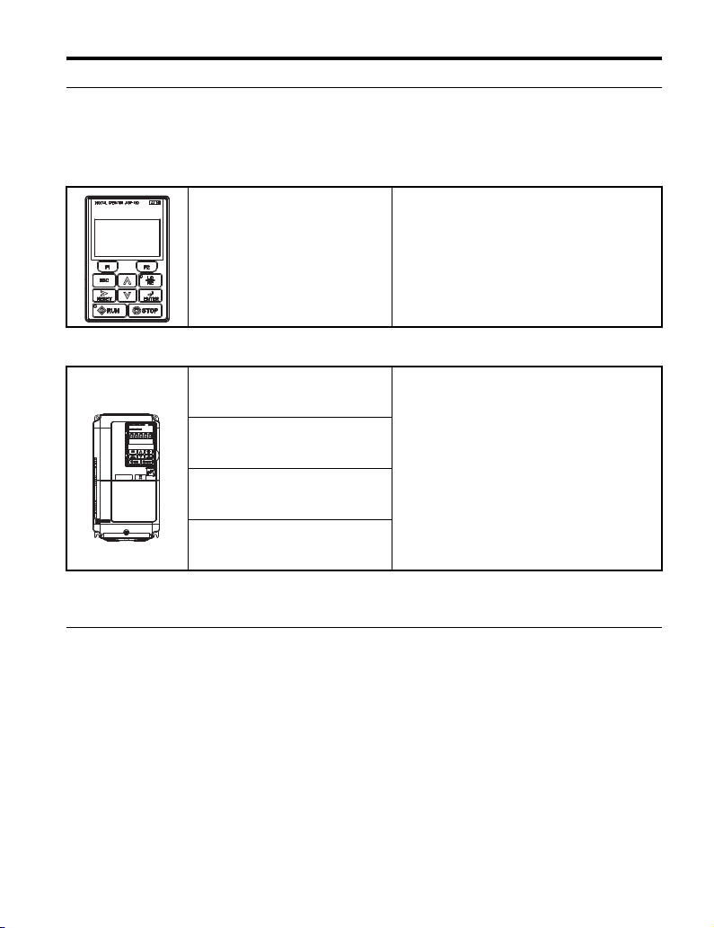
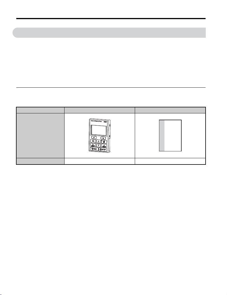
◆ Applicable Documentation
The following manuals are available for the JVOP-180 LCD Operator Option:
LCD Operator
Yaskawa AC Drive 1000-Series
Option LCD Operator
Installation Manual
Manual No: TOBP C730600 29
(this book)
Yaskawa Unit
Yaskawa AC Drive
1000-Series Quick Start Guide
Yaskawa AC Drive
1000-Series Technical Manual
YASKAWA D1000 Series
Power Regenerative Converter
Instruction Manual
YASKAWA R1000 Series
Power Regenerative Unit
Instruction Manual
Note: Check the option to make sure it is compatible with the A1000. The nameplate on the option
must list software number PRG: 0101 or later for compatibility with A1000.
Read this manual first.
The installation manual is packaged with the option
and contains information required to install the
option and set up related unit parameters.
The unit manuals cover basic installation, wiring,
operation procedures, functions, troubleshooting,
and maintenance information.
The manuals also include important information
about parameter settings and unit tuning. Access
these sites to obtain Yaskawa instruction manuals:
U.S.: http://www.yaskawa.com
Europe: http://www.yaskawa.eu.com
Japan: http://www.e-mechatronics.com
For questions, contact your local Yaskawa sales
office or the nearest Yaskawa representative.
◆ Terms
Note: Indicates a supplement or precaution that does not cause unit damage.
≥ PRG: 1012:
LED: Light emitting diode.
LCD: Liquid crystal display.
Option: YASKAWA 1000-Series Option LCD Operator
Unit: • YASKAWA AC Drive 1000-Series
Indicates a unit feature or function that is only available in unit software version 1012 or
greater.
• YASKAWA D1000 Series Power Regenerative Converter
• YASKAWA R1000 Series Power Regenerative Unit
YASKAWA ELECT RIC TOBP C730600 29G 1000-Series Option JVOP-180 Installation Manual 5
Page 6
1 Preface and Safety
W ARNING
CAUTION
NOTICE
Drive: • YASKAWA AC Drive 1000-Series A1000 High Performance Vector Control Drive
Converter: YASKAWA D1000 Series Power Regenerative Converter
Regenerative Unit: YASKAWA R1000 Series Power Regenerative Unit
• YASKAWA AC Drive 1000-Series V1000 Compact Vector Control Drive
◆ Registered Trademarks
Company names and product names listed in this manual are the registered trademarks of
those companies.
◆ Supplemental Safety Information
Read and understand this manual before installing, operating or servicing this option. The
option must be installed according to this manual and local codes.
The following conventions are used to indicate safety messages in this manual. Failure to
heed these messages could result in serious or fatal injury or damage to the products or to
related equipment and systems.
DANGER
Indicates a hazardous situation, which, if not avoided, will result in death or serious
injury.
Indicates a hazardous situation, which, if not avoided, could result in death or
serious injury.
Indicates a hazardous situation, which, if not avoided, could result in minor or
moderate injury.
Indicates an equipment damage message.
6 YASKAWA ELECTRIC TOBP C730600 29G 1000-Series Option JVOP-180 Installation Manual
Page 7
1 Preface and Safety
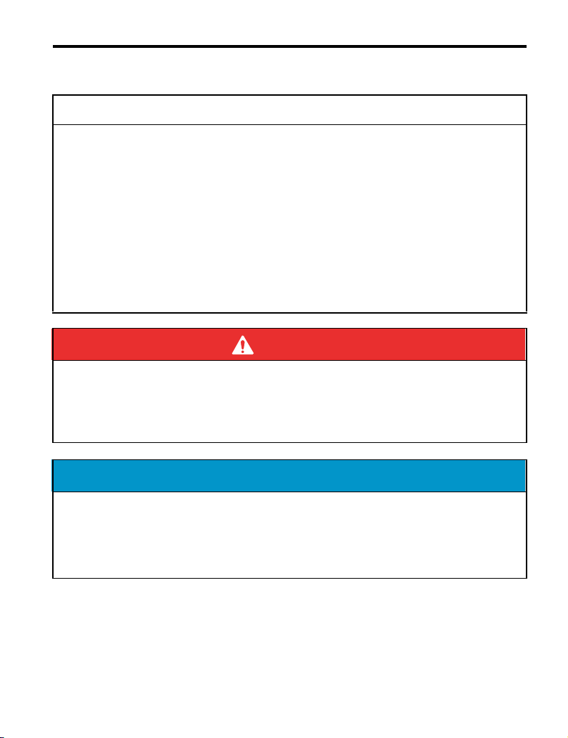
NOTICE
■ General Safety
General Precautions
• The diagrams in this section may include options and units without covers or safety
shields to illustrate details. Be sure to reinstall covers or shields before operating any
devices. The option board should be used according to the instructions described in this
manual.
• Any illustrations, photographs, or examples used in this manual are provided as
examples only and may not apply to all products to which this manual is applicable.
• The products and specifications described in this manual or the content and presentation
of the manual may be changed without notice to improve the product and/or the manual.
• When ordering a new copy of the manual due to damage or loss, contact your Yaskawa
representative or the nearest Yaskawa sales office and provide the manual number
shown on the front cover.
DANGER
Heed the safety messages in this manual.
Failure to comply will result in death or serious injury.
The operating company is responsible for any injuries or equipment damage resulting
from failure to heed the warnings in this manual.
Do not expose the unit to halogen group disinfectants.
Failure to comply may cause damage to the electrical components in the option.
Do not pack the unit in wooden materials that have been fumigated or sterilized.
Do not sterilize the entire package after the product is packed.
YASKAWA ELECT RIC TOBP C730600 29G 1000-Series Option JVOP-180 Installation Manual 7
Page 8
2 Product Overview
2 Product Overview
◆ About This Product
The option provides an enhanced unit user interface that can operate the Yaskawa unit from
up to 3 meters away. The option can display information in 13 languages, including English,
Japanese, and Spanish. <1> <2> The option is an LCD display that simplifies the task of
interfacing with the unit to perform these tasks:
• Read or modify unit parameters.
• Read and copy unit parameter settings to another Yaskawa unit.
• Operate the unit.
• Monitor unit operation status.
<1> Eight languages (English, Japanese, German, French, Italian, Spanish, Portuguese, Chinese) are available when
using one of the following devices:
• An A1000 with drive software version PRG: 1018 or later and option with software version PRG: 0101.
• An A1000 with drive software version PRG: 1017 or later and option with software version PRG: 0101 or later.
• A1000 models 4A0930 or 4A1200
• V1000
<2> Language support is limited to English, Japanese, and Chinese when using the option with software version PRG:
0101 in combination D1000 or R1000.
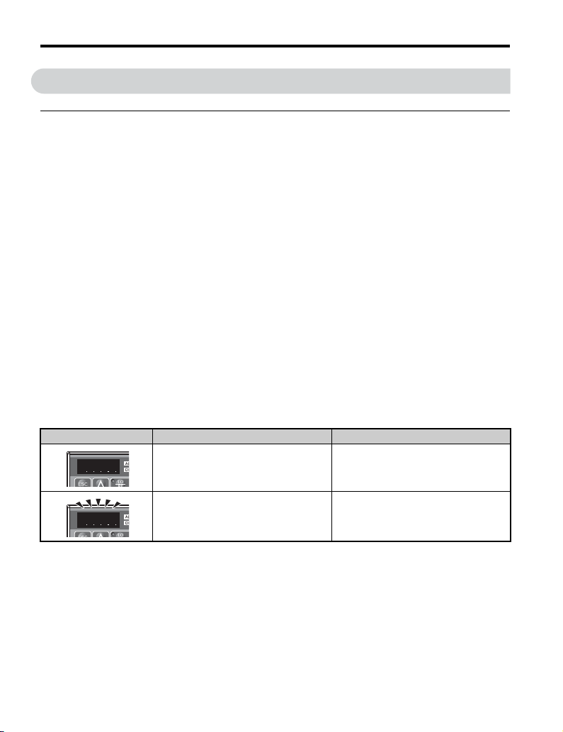
Note: Installing and connecting the option to a V1000 will cause the built-in LED operator on the drive
to display a series of dots as shown in Table 1. This is normal operation. Additionally, when the
option is connected, none of the keys on the built-in LED operator on the drive will work, except
for the STOP key. To disable the STOP key on the built-in LED operator, set parameter o2-02
(STOP Key Function Selection) to 0 (Disabled).
Table 1 Built-in LED Display When Option is Connected to a V1000
Display LED Display Drive Status
Illuminated During Stop
Flashing During Run
8 YASKAWA ELECTRIC TOBP C730600 29G 1000-Series Option JVOP-180 Installation Manual
Page 9

◆ Applicable Models
The option can be used with the unit models in Tab le 2 .
Table 2 Applicable Unit Models
Unit Unit Software Version <1>
A1000 All versions
V1000 ≥ PRG: 1012
D1000 All versions
R1000 All versions
<1> See “PRG” on the unit nameplate for software version number.
2 Product Overview
Note: 1. Check the option to make sure it is compatible with the A1000. The nameplate on the option must list
software version PRG: 0101 or later for compatibility with A1000.
2. To view information on the display in Czech, Russian, Turkish, Polish, or Greek, use option software
version PRG: 0102 or later and A1000 drive software version PRG: 1018 or later. Those languages
cannot be displayed on A1000 models 4A0930 or 4A1200.
3. Language support is limited to English, Japanese, and Chinese when using the option with software
version PRG: 0101 in combination D1000 or R1000.
YASKAWA ELECT RIC TOBP C730600 29G 1000-Series Option JVOP-180 Installation Manual 9
Page 10
3 Receiving
3 Receiving
Perform the following tasks after receiving the option:
• Inspect the option for damage.
If the option appears damaged upon receipt, contact the shipper immediately.
• Verify receipt of the correct model by checking the model number printed on the Name
plate of the option.
• If you have received the wrong model or the option does not function properly, contact
your supplier.
◆ Contents and Packaging
Table 3 Contents of Package
Description: Option Installation Manual
MANUAL
–
Quantity: 11
Parts Sold Separately
■
Proper installation of the option requires a digital operator cable (sold separately). A
communication cable may be purchased from Yaskawa or recommended LAN cables may
be used.
Installation support kit A or B (sold separately) may also be required depending on the
option installation method. Refer to Table 4. Refer to Installing the Option on page 23 for
more information regarding installation methods.
To order a communication or an installation support kit, contact Yaskawa directly or your
nearest Yaskawa distributor.
10 YASKAWA ELECTRIC TOBP C730600 29G 1000-Series Option JVOP-180 Installation Manual
Page 11
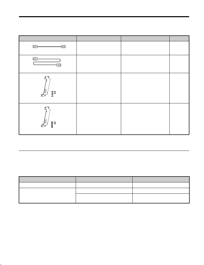
Table 4 Item Names and Part Numbers (Sold Separately)
Item Yaskawa Part Number Notes Page
Digital Operator Cable 1 m (3 ft.)
Digital Operator Cable 3 m (10 ft.)
Part number for the Ame ricas:
<1>
Part number for the Ame ricas:
<1>
WV001
UWR0051
WV003
UWR0052
3 Receiving
Alternate cables (customer-
supplied), RJ45 8-pin Straight
Connector UTP Cat5e cable
Alternate cables (customer-
supplied), RJ45 8-pin Straight
Connector UTP Cat5e cable
26
26
EZZ020642A
Installation Support Kit A
EZZ020642B
Installation Support Kit B
<1> Digital Operator Cable: Used to connect the digital operator to the drive (sold separately).
<2> Use Installation Support Kit B when weld studs are on the back of the panel.
<2>
Sold Separately;
For use with holes through the
For use with panel-mounted
panel
Sold Separately;
threaded studs
◆ Tool Requirements
The tools listed in Table 5 are required to install the option on an enclosure panel door.
Table 5 Required Tools
Installation Location Installation Support Required Tools
External/Face Mount – Phillips screwdriver, M3
Internal/Flush Mount
Installation Support Kit A Phillips screwdriver, M3, M4
Installation Support Kit B
Phillips screwdriver, M3
Box end or adjustable wrench, M4
25
25
YASKAWA ELECT RIC TOBP C730600 29G 1000-Series Option JVOP-180 Installation Manual 11
Page 12
4 Option Components
A
4 Option Components
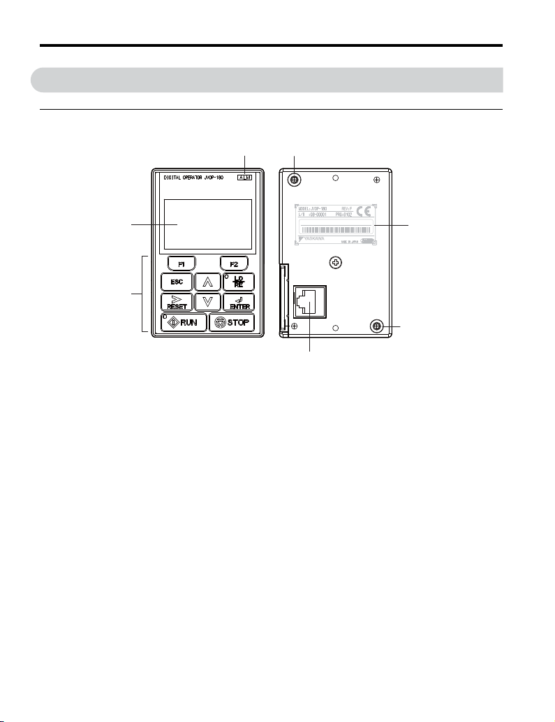
◆ Option
Figure 1
B
D
C
A – LCD Display
B – ALARM (ALM) LED E – Nameplate
C – Keys F – Communication Cable Connector
<1> REV: Display option version; PRG: Language data.
S /N : J007XE273710001
F
D – Installation Mounting Holes
Figure 1 Option Components
E
D
<1>
12 YASKAWA ELECTRIC TOBP C730600 29G 1000-Series Option JVOP-180 Installation Manual
Page 13
4 Option Components
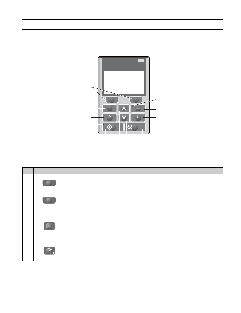
◆ Keys
Refer to Figure 2 and Table 6 for details on key names and functions.
Figure 2
DIGITAL OPERATOR JVOP-180
1
ALM
F2F1
2
ESC
3
10
RUN STOP
LO
RE
ENTERRESET
11
9
8
456 7
Figure 2 Keys
Table 6 Key Names and Functions
No. Key Name Function
F1
1
F2
Function Key
(F1, F2)
2ESC Key
3 RESET Key
The functions assigned to F1 and F2 vary depending on the menu that is
currently displayed. The name of each function appears in the lower half
of the display window.
For a description of functions assigned to the F1 and F2 keys, Refer to
LCD Display on page 18.
• Returns to the previous display.
• Moves the cursor one space to the left.
• Pressing and holding this button will return to the following display:
Drive: Frequency Reference
Converter: DC Bus Voltage Reference
Regenerative unit: DC Bus Voltage
• Moves the cursor to the right.
• Resets the unit to clear a fault situation.
YASKAWA ELECT RIC TOBP C730600 29G 1000-Series Option JVOP-180 Installation Manual 13
Page 14
4 Option Components
U
U
N
SOO
P
RE
LO
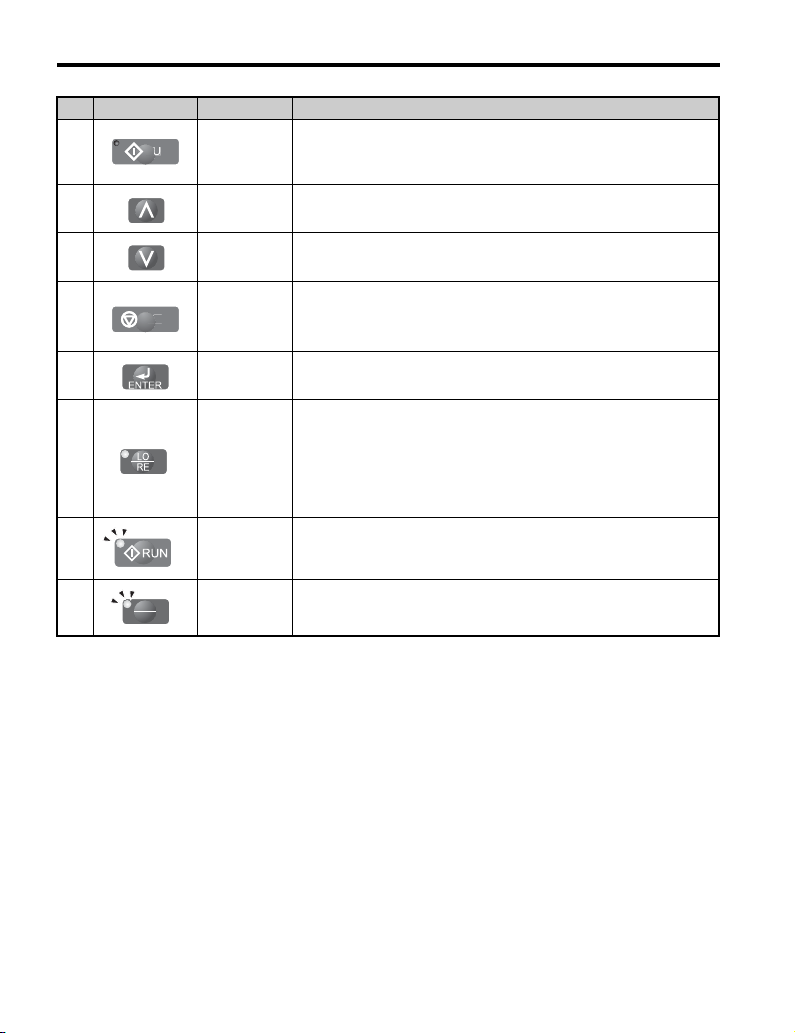
No. Key Name Function
4 RUN Key Starts the unit and motor.
5 Up Arrow Key
6
Down Arrow
Key
Scrolls up to display the next item, selects parameter numbers and
increments setting values.
Scrolls down to display the previous item, selects parameter numbers and
decrements setting values.
Stops unit operation.
7STOP Key
8ENTER Key
9
LO/RE
Selection Key
Note: The STOP key can be enabled or disabled when operating from the
external terminal or network communications by setting parameter o2-02.
• Enters parameter values and settings.
• Selects a menu item to move between displays.
Switches unit control between the operator (LOCAL) and an external
source (REMOTE) for the Run command and frequency reference.
Note: The LOCAL/REMOTE key is only effective when the unit is
stopped in Drive Mode. As a safety precaution, it is possible to disable the
LO/RE Selection Key by setting parameter o2-01 (LOCAL/REMOTE
Key Function Selection) to 0 (disabled).
10 RUN Light
Illuminated during an operation.
Refer to Option LED Status Indicators on page 15 for details.
11 LO/RE Light Illuminated while the option is selected to run the unit (LOCAL mode).
14 YASKAWA ELECTRIC TOBP C730600 29G 1000-Series Option JVOP-180 Installation Manual
Page 15
4 Option Components
Flashing
quickly
Flashing
ON ON
ON
ON ON
ON
1 s
Drive output frequency
During stop
Frequency setting
OFF ON
Flashing
OFF
OFF
RUN LED
STOP STOP
RUN
0 Hz
6 Hz
RUN
/
RUN STOP
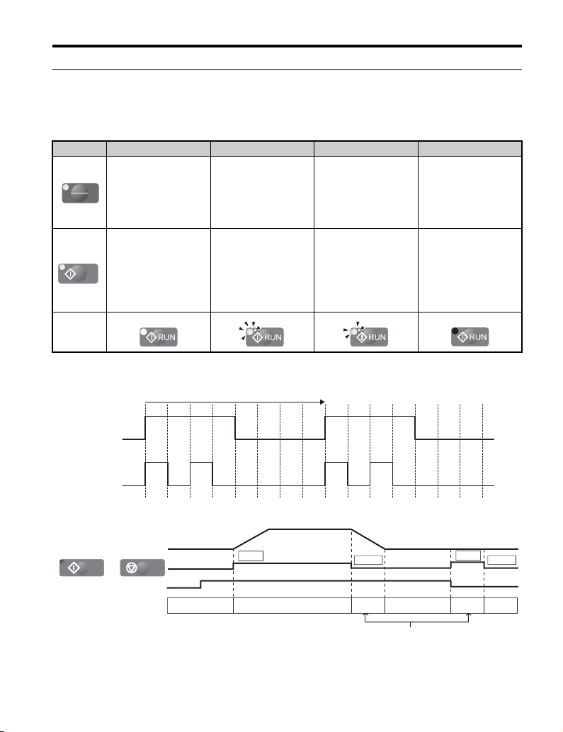
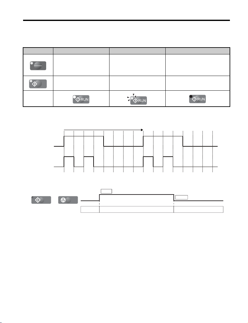
◆ Option LED Status Indicators
■ Connecting the Option to A1000 or V1000
Table 7 LED Status and Meaning
LED Illuminated Flashing <1>
When the option is
selected for Run
LO
command and
RE
frequency reference
control (LOCAL).
• During deceleration to
During run.
RUN
Examples
<1> Refer to Figure 3 for the difference between “flashing” and “flashing quickly”.
Figure 3
• When a Run
––
stop.
command is input and
the frequency
reference is 0 Hz.
Flashing Quickly <1> Off
• During deceleration
when a Fast Stop
command was
entered.
• During stop by
External Fault digital
input.
When a device other
than the option is
selected for Run
command and
frequency reference
control (REMOTE).
During stop.
Figure 4
YASKAWA ELECT RIC TOBP C730600 29G 1000-Series Option JVOP-180 Installation Manual 15
Figure 3 RUN LED Status
Figure 4 RUN LED and Drive Operation
Page 16
4 Option Components
RUN
/
RUN STOP
RUN LED OFF OFFON
DC bus voltage reference
DC bus voltage
STOP
RUN
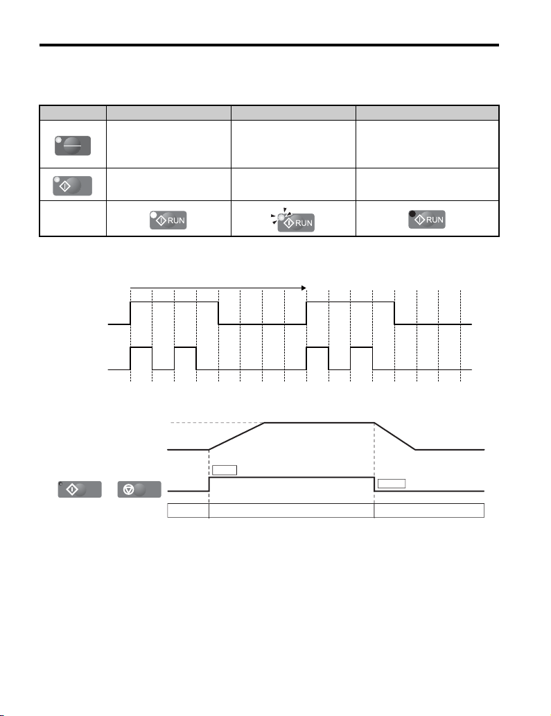
■ Connecting the Option to D1000
Table 8 LED Status and Meaning
LED Illuminated Flashing Quickly <1> Off
LO
RE
When the run command is
selected from the LED
operator (LOCAL).
During run.
–
During stop by External Fault
digital input.
Examples
<1> Refer to Figure 5 for the difference between “flashing” and “flashing quickly”.
Figure 5
1 s
When a device other than the
option is selected for Run
command and frequency reference
control (REMOTE).
During stop.
ON
ON
Flashing
Flashing
quickly
ON ON
ON ON
Figure 5 RUN LED Status
Figure 6
Figure 6 RUN LED and Converter Operation
16 YASKAWA ELECTRIC TOBP C730600 29G 1000-Series Option JVOP-180 Installation Manual
Page 17
4 Option Components
RUN
/
RUN STOP
RUN LED OFF OFFON
STOP
RUN
■ Connecting the Option to R1000
Table 9 LED Status and Meaning
LED Illuminated Flashing Quickly <1> Off
LO
RE
When the run command is
selected from the LED
operator (LOCAL).
During run.
–
During stop by External Fault
digital input.
Examples
<1> Refer to Figure 7 for the difference between “flashing” and “flashing quickly”.
Figure 7
1 s
When a device other than the
option is selected for Run
command and frequency reference
control (REMOTE).
During stop.
Flashing
ON
ON ON
Flashing
quickly
Figure 7 RUN LED Status
Figure 8
Figure 8 RUN LED and Regenerative Unit Operation
YASKAWA ELECT RIC TOBP C730600 29G 1000-Series Option JVOP-180 Installation Manual 17
ON
ON ON
Page 18
4 Option Components
㪴
7
6
5
1234
1098
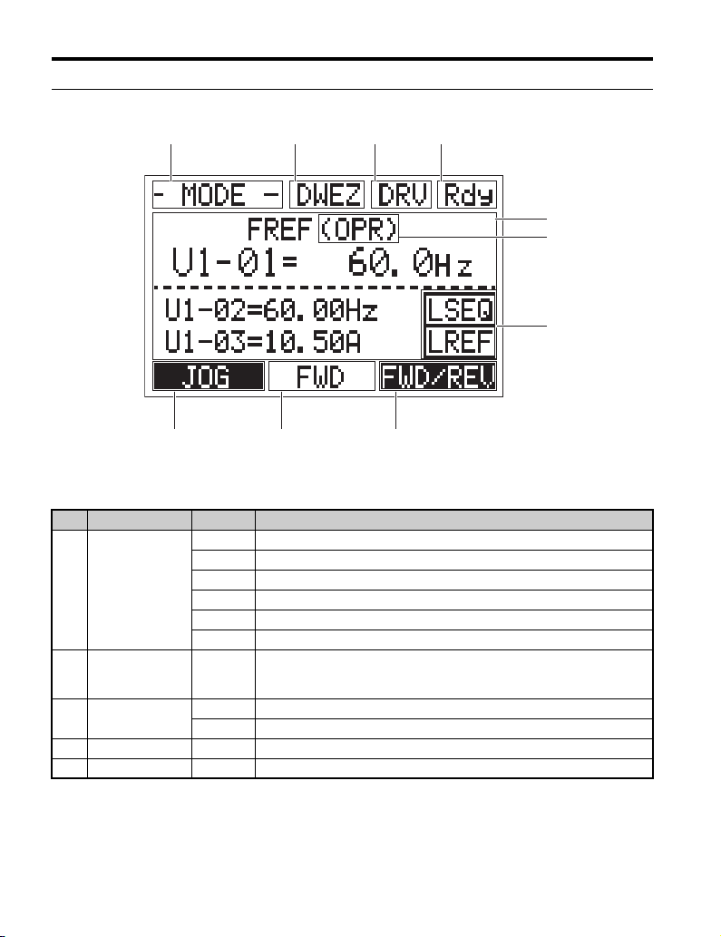
◆ LCD Display
Figure 9
Figure 9 LCD Display
Table 10 Display and Contents
No. Name Display Content
MODE Displayed when in Mode Selection.
MONITR Displayed when in Monitor Mode.
Operation Mode
1
Menus
DriveWorksEZ
2
Function Selection
<1>
3 Mode Display Area
4 Ready Rdy Indicates the unit is ready to run.
5 Data Display – Displays specific data and operation data.
VERIFY Indicates the Verify Menu.
PRMSET Displayed when in Parameter Setting Mode.
A.TUNE Displayed during Auto-Tuning.
SETUP Displayed when in Setup Mode.
DWEZ
Displayed when the DriveWorksEZ is set to enable.
(A1-07 = 1 or 2)
DRV Displayed when in Drive Mode.
PRG Displayed when in Programming Mode.
18 YASKAWA ELECTRIC TOBP C730600 29G 1000-Series Option JVOP-180 Installation Manual
Page 19

4 Option Components
No. Name Display Content
OPR Displayed when the frequency reference is assigned to the option.
Displayed when the frequency reference is assigned to the Analog Input of
AI
Drive:
Frequency
Reference
Assignment
Converter:
6
Voltage Reference
Assignment
Regenerative Unit:
Run Command
Assignment
LO/RE
7
Display
<2>
<2>
AUTO
<2>
RSEQ Displayed when the Run command is supplied from a remote source.
LSEQ Displayed when the Run command is supplied from the digital operator.
RREF
<3>
LREF
the drive.
Displayed when the frequency reference is assigned to the MEMOBUS/
COM
Modbus Communication Inputs of the drive.
Displayed when the frequency reference is assigned to an Option Unit of the
OP
drive.
Displayed when the frequency reference is assigned to the Pulse Train Input
RP
of the drive.
OPR Displayed when the voltage reference is assigned to the option.
Displayed when the voltage reference is assigned to the Analog Input of the
AI
converter.
Displayed when the voltage reference is assigned to the MEMOBUS/
COM
Modbus Communication Inputs of the converter.
Displayed when the voltage reference is assigned to an Option Unit of the
OP
converter.
Displayed when b1-18 is set to either 7 or 8 (input voltage based control 1 or
2).
OPR Displayed when the Run command is assigned to the option.
Displayed when the Run command is assigned to the Analog Input of the
AI
regenerative unit.
Displayed when the Run command is assigned to the MEMOBUS/Modbus
COM
Communication Inputs of the regenerative unit.
Displayed when the Run command is assigned to an Option Unit connected
OP
to the regenerative unit.
Drive: Displayed when the frequency reference is supplied from a remote
source.
Converter: Displayed when the voltage reference is supplied from a remote
source.
Regenerative unit: Displayed when the Run command is supplied from a
remote source.
Drive: Displayed when the frequency reference is supplied from the digital
operator.
Converter: Displayed when the voltage reference is supplied from the digital
operator.
Regenerative unit: Displayed when the Run command is supplied from the
digital operator.
YASKAWA ELECT RIC TOBP C730600 29G 1000-Series Option JVOP-180 Installation Manual 19
Page 20

4 Option Components
F1
F1
F1
F2
F2
No. Name Display Content
JOG
Pressing executes the Jog function.
<1>
8
HELP
Function Key 1
(F1)
HOME
Pressing displays the Help menu.
←
Pressing scrolls the cursor to the left.
Pressing will return to the following display:
Drive: Frequency Reference
Converter: DC Bus Voltage Reference
F1
Regenerative unit: DC Bus Voltage
ESC
Pressing returns to the previous display.
FWD/REV
9
10
<1> Not available for the converter and regenerative unit.
<2> Displayed when in Frequency Reference, Voltage Reference, or Run Command Mode.
<3> Displayed when in Frequency Reference, Voltage Reference, or Run Command Mode and Monitor Mode.
<1>
Function Key 2
(F2)
FWD Indicates forward motor operation.
REV Indicates reverse motor operation.
FWD/REV
DATA
RESET
Pressing switches between forward and reverse.
<1>
Pressing scrolls to the next display.
→
Pressing scrolls the cursor to the right.
Pressing resets the existing unit fault or error.
F1
F2
F2
20 YASKAWA ELECTRIC TOBP C730600 29G 1000-Series Option JVOP-180 Installation Manual
Page 21

4 Option Components
◆ ALARM (ALM) LED Displays
Table 11 ALARM (ALM) LED Status and Contents
State Content Display
Illuminated When the unit detects an alarm or error.
Flashing
Off Normal operation (no fault or alarm).
• When an alarm occurs.
• When oPE is detected.
• When a fault or error occurs during Auto-Tuning.
YASKAWA ELECT RIC TOBP C730600 29G 1000-Series Option JVOP-180 Installation Manual 21
Page 22

5 Installation Procedure
NOTICE
5 Installation Procedure
◆ Section Safety
Damage to Equipment
Use only Yaskawa connection cables or recommended cables.
Failure to comply may cause the unit or option to function incorrectly.
Properly connect the connectors.
Failure to comply may prevent proper operation and possibly damage equipment.
Do not exceed communication cable bend radius specifications.
Failure to comply may result in broken wires or loose connections.
22 YASKAWA ELECTRIC TOBP C730600 29G 1000-Series Option JVOP-180 Installation Manual
Page 23

◆ Option Dimensions
Figure 10
12.2
(0.48)
1.6 (0.06)
5 Installation Procedure
Installation holes
(2-M3 screws, depth 5 (0.2))
S /N : J007XE273710001
90 (3.54)
15
(0.59)
44 (1.73)
60 (2.36)
<1>
7.9
(0.31)
minimum 50 (1.97) Unit : mm (in.)
Figure 10 Dimensions
<1> Use only Yaskawa cables or cables recommended by Yaskawa. Refer to Item
Names and Part Numbers (Sold Separately) on page 11.
◆ Installing the Option
The option mounts to an enclosure two different ways:
• External/face-mount installs the operator outside the enclosure panel.
• Internal/flush-mount installs the operator inside the enclosure panel.
Table 12 Option Installation Methods
Installation Method Description Notes
External/Face-mount
Internal/Flush-mount
Simplified installation with the option is mounted on the
outside of the panel with two screws.
Encloses the option in the panel. The front of the option is
flush with the outside of the panel.
Requires purchase of
separate items. Refer to Item
Names and Part Numbers
(Sold Separately) on
page 11.
78 (3.07)
–
YASKAWA ELECT RIC TOBP C730600 29G 1000-Series Option JVOP-180 Installation Manual 23
Page 24
5 Installation Procedure
M3 × 6 (0.24)
Phillips recessed
pan head machine screw × 2
Unit: mm (in.)
Option
Enclosure panel
22 (0.87)
22(0.87)
14
(0.55) Unit: mm (in.)
26
(1.02)
22
(0.87)
78 (3.07)
2 (0.08)
NOTICE: Prevent foreign matter such as metal shavings or wire clippings from falling into the unit during
installation and project construction. Failure to comply could result in damage to the unit. Place a temporary
cover over the top of the unit during installation. Remove the temporary cover before startup, as the cover
will reduce ventilation and cause the unit to overheat.
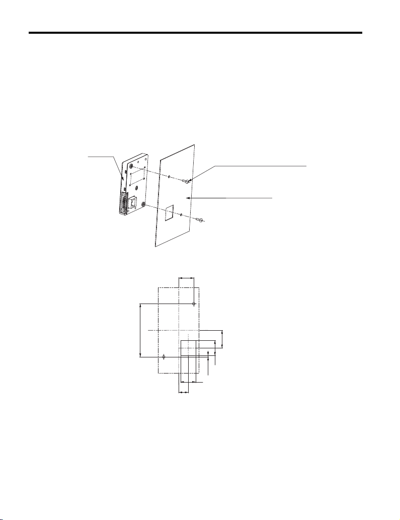
■ External/Face-mount Installation
1. Cut an opening in the enclosure panel for the option according to Figure 12.
2. Position the option so the LCD display faces outwards, and mount it to the
Figure11
enclosure panel as shown in Figure 11.
Figure 12
Figure 12 Panel Cut-out Dimensions (External/Face-mount Installation)
24 YASKAWA ELECTRIC TOBP C730600 29G 1000-Series Option JVOP-180 Installation Manual
Figure 11 External/Face-mount Installation
Page 25

5 Installation Procedure
120 (4.72)
Unit: mm (in.)
45 (1.77)
89
+0.5
0
35 )(
+0.02
0
59
+0.5
0
2.32 )(
+0.02
0
■ Internal/Flush-mount Installation
The internal flush-mount installation method requires an installation support that is
purchased separately. Refer to Item Names and Part Numbers (Sold Separately) on
page 11 for information regarding the installation support and mounting hardware.
Figure 13 illustrates how to install Installation Support Kit A.
1. Cut an opening in the enclosure panel for the option according to Figure 14.
2. Mount the option to the installation support (sold separately).
3. Mount the installation support and option to the enclosure panel.
Figure 13
Enclosure panel
M4 × 10 (0.39)
Phillips truss head screw × 4
(for panel widths between 1 (0.04)
and 1.6 (0.06))
Option
Installation Support Kit A
M3 × 6 (0.24)
Phillips recessed pan head
machine screw × 2
Unit:mm (in.)
Figure 13 Internal/Flush Mount Installation
Note: For environments with a significant amount of dust or other airborne debris, use a gasket
Figure 14
between the enclosure panel and the option.
Figure 14 Panel Cut-out Dimensions (Internal/Flush-mount Installation)
YASKAWA ELECT RIC TOBP C730600 29G 1000-Series Option JVOP-180 Installation Manual 25
Page 26

5 Installation Procedure
STOP
V1000
(Hz)
(Hz)
(A)
(V)
:
:
:
:
:
:
:
:
:
:
周波数指令
正転逆転選択
出力周波数
出力電流
出力電圧
モニタ
ベリファイ
セットアップ
パラメータ設定
オートチューニング
据え付け、運転の前には必ず取扱説明書を読むこと。
通電中および電源遮断後
5
分以内はフロントカバーを
外さないこと。
400V
級インバータの場合は、電源の中性点が接地
されていることを確認すること。( 対応)
けが、感電のおそれがあります。
危 険
Read manual before installing.
Wait 5 minutes for capacitor discharge after
disconnecting power supply.
To conform to requirements, make sure
to ground the supply neutral for 400V class.
Risk of electric shock.
WARNING
S /N : J007XE273710001
Comm Port
LED
Operator
Communication Cable Connector
OptionDrive
◆ Connecting the Option to the Unit
This section contains instructions for connecting the option to units.
■ Connecting the Option to V1000
Plug the customer-supplied communication cable into the communication cable connector of
the option and the drive communications port as shown in Figure 15. Ensure both cable
ends are firmly connected. Refer to Item Names and Part Numbers (Sold Separately) on
page 11 for information regarding recommended cables.
Refer to Table 1 for built-in LED display behavior with a connected option.
Note: 1. Use only Yaskawa recommended cables. Using a cable not specified may cause the option or drive to
Figure 15
malfunction.
2. The STOP key on the built-in LED operator of the drive is the only functional key on the drive when the
option is connected and parameter b1-02 is set to 0 (LCD Operator or Option). Set parameter o2-02
(STOP Key Function Selection) to 0 (Disable) to disable the STOP key.
Figure 15 Communication Cable Connection
26 YASKAWA ELECTRIC TOBP C730600 29G 1000-Series Option JVOP-180 Installation Manual
Page 27

5 Installation Procedure
■ Connecting the Option to A1000, D1000, or R1000
Plug the customer-supplied communication cable into the communication cable connector of
the option and the unit communications port as shown in Figure 15. Ensure both cable ends
are firmly connected. Refer to Item Names and Part Numbers (Sold Separately) on page 11
for information regarding recommended cables.
Note: Use only Yaskawa recommended cables. Using a cable not specified may cause the option or
Figure 16
unit to malfunction.
OptionUnit
Comm Port
S /N : J007XE273710001
Communication Cable Connector
Figure 16 Communication Cable Connection
YASKAWA ELECT RIC TOBP C730600 29G 1000-Series Option JVOP-180 Installation Manual 27
Page 28

6 Basic Operation
<1> Pressingޓg will start the motor.
<2> Drive cannot operate the motor.
<3> Flashing characters are shown as .
<4> X characters are shown in this manual.
The option will display the actual setting
values.
<5> The Frequency Reference appears after
the initial display which shows the product name.
<6> The information that appears on the display will
vary depending on the drive.
- MODE -
U1-01= 0.00Hz
U1-02= 0.00Hz
U1-03= 0.00A
DRV
FREF (OPR)
Rdy
-MONITR-
FREF (d1-01)
U1-01= 000.00Hz
<3>
<4>
㧔0.00㨪60.00㧕
0.00Hz
DRV
←→
FWD
Rdy
- MODE -
U1-01= 0.00Hz
U1-02= 0.00Hz
U1-03= 0.00A
DRV
Monitor Menu
Rdy
- MODE - PRG
Modified Consts
HELP
HELP
DATA
- MODE - PRG
Quick Setting
DATA
HELP
- MODE - PRG
Auto-Tuning
DATA
HELP
- MODE - PRG
DATA
Programming
AUTO
-MONITR-
U1 -01= 0.00Hz
U1-02= 0.00Hz
U1-03= 0.00A
DRV
Monitor
JOG FWD FWD/REV
Rdy
-MONITR-
U1- 01 = 0.00Hz
U1-02= 0.00Hz
U1-03= 0.00A
DRV
Frequency Ref
JOG FWD FWD/REV
Rdy
-MONITR-
U1- 02 = 0.00Hz
U1-03= 0.00A
U1-04= 0
DRV
Output Freq
JOG FWD FWD/REV
Rdy
-MONITR-
U2 -01= oC
U2-02= oPr
U2-03= 0.00Hz
DRV
Fault Trace
JOG FWD FWD/REV
Rdy
JOG FWD FWD/REV
JOG FWD
FWD
FWD
FWD
FWD
FWD/REV
Modified
X Parameters
Drive
Mode
<1>
Programming
Mode
<2>
LSEQ
LREF
LSEQ
LREF
LSEQ
LREF
LSEQ
LREF
LSEQ
LREF
LSEQ
LREF
YAS K A W A
V1000
V1000
XXXVX.X/X.XkW
XX.XX/XX.XXA
<XXXXXXXXX>
Initial Display <5>
<6>
RUN
0
6 Basic Operation
◆ Connecting the Option to A1000 or V1000
■ Menu Structure for Option
Figure 17
28 YASKAWA ELECTRIC TOBP C730600 29G 1000-Series Option JVOP-180 Installation Manual
Figure 17 Option Menu Structure
Page 29

6 Basic Operation
←→
-MONITRFREF (d1-01)
U1-01= 000.00Hz
㧔0.00㨪60.00㧕
0.00Hz
DRV
FWD
Rdy
Entry Accepted
■ Example: Basic Operation
The following procedures are examples of drive operation using the option.
Note: Actual LCD display data varies based on drive parameter settings.
Procedure Example: RUN/STOP
Note: If b1-01 is not set to 0 (Operator), press to set LOCAL.
Procedure LCD Display
1. Apply main power to the drive. The Frequency Reference appears after the initial
display on the option.
2. Press to show the display for inputting the frequency reference.
If b1-01 is not set to 0 (Operator), press to set LOCAL.
LO
RE
- MODE -
U1-01= 0.00Hz
U1-02= 0.00Hz
U1-03= 0.00A
JOG FWD FWD/REV
LO
RE
DRV
FREF (OPR)
Rdy
LSEQ
LREF
3. Press until the frequency
4. Press to set the output frequency.
YASKAWA ELECT RIC TOBP C730600 29G 1000-Series Option JVOP-180 Installation Manual 29
F1 F2
reference changes to 006.00 Hz.
-MONITR-
U1-01= 006.00Hz
㧔0.00㨪60.00㧕
←→
DRV
FREF (d1-01)
0.00Hz
FWD
Rdy
Page 30

6 Basic Operation
RUN
←→
-MONITRFREF (d1-01)
U1-01= 006.00Hz
㧔0.00㨪60.00㧕
0.00Hz
DRV
FWD
Rdy
- MODE -
U1-01= 6.00Hz
U1-02= 0.00Hz
LSEQ
LREF
U1-03= 0.00A
DRV
Monitor Menu
Rdy
JOG FWD FWD/REV
-MONITR-
U2-03= 0.00Hz
U2-04= 0.00Hz
DRV
Last Fault
JOG FWD FWD/REV
Rdy
LSEQ
LREF
U2 -02= oPr
Procedure LCD Display
5. Press to start the motor. The motor should accelerate up to 6 Hz while
the RUN LED is on.
6. Press to stop the motor. The RUN LED will flash until the motor
comes to a complete stop.
Procedure Example: Viewing Monitors
Procedure LCD Display
1. Frequency Reference display.
2. Press until the Monitor Menu display appears.
DRV
- MODE FREF(OPR)
U1-01= 0.00Hz
U1-02= 0.00Hz
U1-03= 0.00A
JOG FWD FWD/REV
Rdy
LSEQ
LREF
-MONITR-
3. Press to show the Monitor display.
4. Press to view the drive monitors.
30 YASKAWA ELECTRIC TOBP C730600 29G 1000-Series Option JVOP-180 Installation Manual
U1 -01= 6.00Hz
U1-02= 0.00Hz
U1-03= 0.00A
JOG FWD FWD/REV
Monitor
DRV
Rdy
LSEQ
LREF
Page 31

6 Basic Operation
HELP
-MODE- PRG
DATA
Programming
FWD
←→
-PRMSET-
ゲンゴ
㧔Language㧕
A1-00=1 *0*
ニホンゴ
㧔Japanese㧕
PRG
FWD
1
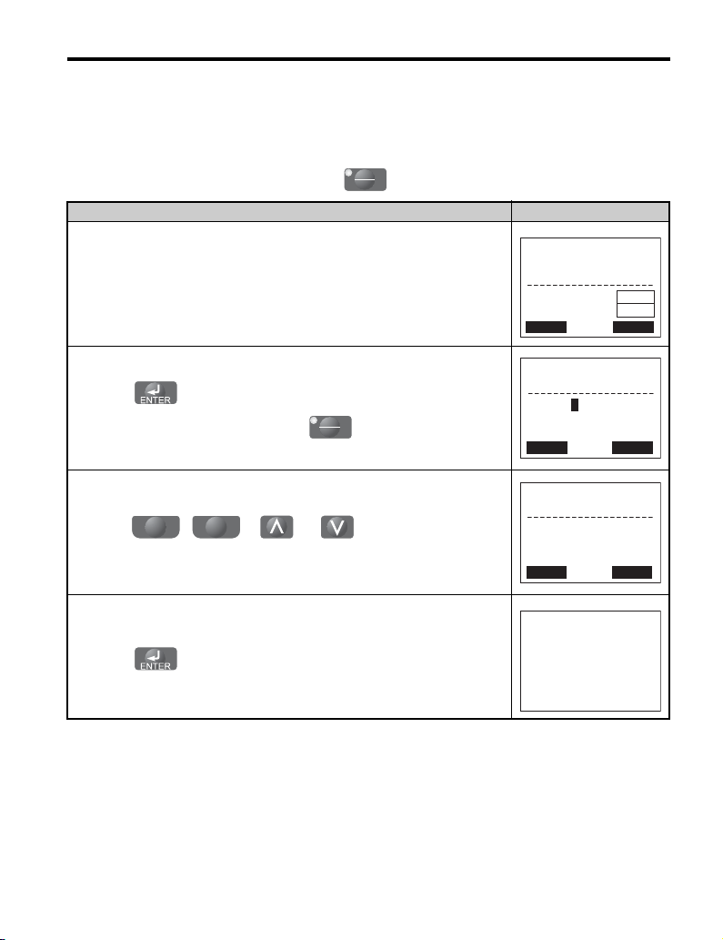
Procedure Example: Display Language Selection
The display language can be changed with parameter A1-00 (Select Language).
Procedure LCD Display
- MODE FREF(OPR)
1. Frequency Reference.
2. Press to select the Programming Mode.
U1-01= 0.00Hz
U1-02= 0.00Hz
U1-03= 0.00A
JOG FWD FWD/REV
DRV
Rdy
LSEQ
LREF
3. Press to show the Initialization display.
4. Press to select A1-00 and
5. Press to enter setting 1.
YASKAWA ELECT RIC TOBP C730600 29G 1000-Series Option JVOP-180 Installation Manual 31
F1 F2
press .
-PRMSET-
A1-00=0
Select Language
←→
-PRMSET-
Select Language
A1-00=0 *0*
←→
PRG
Initialization
FWD
PRG
English
“1”
FWD
Page 32

6 Basic Operation
- MODE -
U1-01= 0.00Hz
U1-02= 0.00Hz
U1-03= 0.00A
DRV
FREF(OPR)
Rdy
JOG FWD FWD/REV
LSEQ
LREF
HELP
-MODE- PRG
DATA
Programming
FWD
Procedure LCD Display
6. Press and the option will display Japanese.
䉦䉨䉮䊚㩷䉦䊮䊥䊢䉡
Procedure Example: Setting Parameters
The example below explains how to change the Deceleration Time parameter C1-01 to 20.0
sec from the default setting of 10.0 sec.
Procedure LCD Display
1. Frequency Reference display.
2. Press to select the Programming Mode.
3. Press to show the Initialization display.
-PRMSET-
A1-00=0
Select Language
←→
PRG
Initialization
FWD
-PRMSET-
4. Press to select parameter C1-01
F1 F2
and press .
Accel Time 1
C1-01= 0010.0Sec
(0.0~6000.0)
“10.0 sec”
←→
32 YASKAWA ELECTRIC TOBP C730600 29G 1000-Series Option JVOP-180 Installation Manual
PRG
FWD
Page 33

6 Basic Operation
-PRMSET-
C1-01=0020.0Sec
(0.0~6000.0)
“10.0 sec”
PRG
Accel Time 1
←→
FWD
Procedure LCD Display
5. Press to enter 20.0 sec.
6. Press to enter and store the new setting for C1-01.
F1 F2
Entry Accepted
YASKAWA ELECT RIC TOBP C730600 29G 1000-Series Option JVOP-180 Installation Manual 33
Page 34

6 Basic Operation
←→
-PRMSETInitialization
Select Language
PRG
FWD
A1-00=0
Read/Copy Function Procedure
•Read
Reads and saves parameter settings from the drive to the option.
Note: The option can perform the Read function an estimated 100,000 times.
• Copy
Copies parameter settings from the option to another Yaskawa drive.
These parameters control the Copy function of the digital operator. The Copy function
stores parameter settings into the memory of the digital operator to facilitate the transfer
of those settings to other drives that are the same model, capacity, and same control mode
setting.
Note: Parameter settings can only be copied to other drives that are the same model, capacity, and have
•Verify
The following procedure is used to read parameters from the drive.
the same control mode setting.
Verifies that parameter settings in the drive match the parameter settings saved to the
option.
Note: Set parameter o3-02 (Read Allowable) to 1 (Enable) to read the parameter settings from the
drive.
Set parameter o3-02 to 0 (Disable) to protect the parameter settings in the option.
Procedure LCD Display
- MODE FREF (OPR)
1. Frequency Reference display.
2. Press to select the Programming Mode.
3. Press to show the Initialization display.
34 YASKAWA ELECTRIC TOBP C730600 29G 1000-Series Option JVOP-180 Installation Manual
U1-01= 6.00Hz
U1-02= 0.00Hz
U1-03= 0.00A
JOG FWD FWD/REV
-MODE- PRG
Programming
HELP
FWD
DRV
Rdy
LSEQ
LREF
DATA
Page 35

Procedure LCD Display
F1
F2
←→
-PRMSETCopy Funtion Sel
COPY SELECT
PRG
FWD
o3-01= 0 *0*
INV→OP READING
READ
4. Press to select o3-01 and press
.
6 Basic Operation
5. Press to enter 1 (INV --> OP READ).
6. Press and the option will read the parameter settings from the drive.
7. Automatically return to the Copy Function Selection display.
-PRMSETCopy Funtion Sel
o3-01= 1 *0*
INV→OP READ
←→
READ COMPLETE
PRG
0
FWD
End
YASKAWA ELECT RIC TOBP C730600 29G 1000-Series Option JVOP-180 Installation Manual 35
Page 36

6 Basic Operation
◆ Connecting the Option to D1000
■ Menu Structure for Option
Figure 18
DRV
-
Volt Ref
DRV
Modified
Rdy
LSEQ
RREF
Rdy
LSEQ
LREF
DATA
DATA
<4>
U1-51= 0660V
U1-51= 660V
U1-52= 441V
U1-53= 0.0A
-MONITR-
U2-01= - - - - -
U2-02= ov
U2-11=
Initial Display <5>
Drive
Mode
<1>
Programming
<2>
Mode
-
MODE
U1-51= 660V
U1-52= 441V
U1-53= 0.0A
-MONITR-
Monitor Menu
U1-51= 660V
U1-52= 441V
U1-53= 0.0A
- MODE - PRG
Modified Consts
X Parameters
HELP
- MODE - PRG
Quick Setting
HELP
- MODE - PRG
Programming
DRV
-MONITR-
㧔600㨪730㧕
←→
-MONITR-
Volt Ref
660V
DRV
Monitor
DRV
Fault Trace
00000000
D1000
YAS K A W A
Rdy
Rdy
LSEQ
LREF
Rdy
LSEQ
LREF
<3>
-MONITR-
DC V Command
U1-51= 660V
U1-52= 441V
U1-53= 0.0A
-MONITRMessage ID(CNV)
U1-28 = 2892
U1-51= 660V
U1-52= 441V
XXXV, XXXkW
XXX.XXA
<XXXXXXXXX>
DRV
DRV
Rdy
LSEQ
LREF
Rdy
LSEQ
LREF
<6>
HELP
DATA
<1> Pressingޓg will start the converter.
<2> Converter cannot operate.
<3> Flashing characters are shown as .
<4> X characters are shown in this manual.
The option will display the actual setting
values.
<5> The DC Bus V
the initial display which shows the product name.
<6> The information that appears on the display will
vary depending on the converter.
RUN
0
oltage Reference appears after
Figure 18 Option Menu Structure
36 YASKAWA ELECTRIC TOBP C730600 29G 1000-Series Option JVOP-180 Installation Manual
Page 37
6 Basic Operation
←→
-MONITR-
Volt Ref
U1-51= 0330V
㧔300㨪360㧕
330V
DRV Rdy
Entry Accepted
■ Example: Basic Operation
The following procedures are examples of converter operation using the option.
Note: Actual LCD display data varies based on converter parameter settings.
Procedure Example: RUN/STOP
Note: If b1-18 is not set to 0 (Operator), press to set LOCAL.
Procedure LCD Display
1. Apply main power to the converter. The DC Bus Voltage Reference appears after
the initial display on the option.
2. Press to show the display for inputting the DC Bus voltage reference.
If b1-18 is not set to 0 (Operator), press to set LOCAL.
LO
RE
- MODE -
Volt Ref
U1-51= 0330V
U1-52= 295V
U1-53= 0.0A
LO
RE
DRV
Rdy
LSEQ
LREF
YASKAWA ELECT RIC TOBP C730600 29G 1000-Series Option JVOP-180 Installation Manual 37
3. Press until the DC bus voltage
4. Press to set the output voltage.
F1 F2
reference changes to the desired voltage.
-MONITR-
U1-51= 320V
DRV Rdy
Volt Ref
㧔300㨪360㧕
330V
←→
Page 38

6 Basic Operation
- MODE -
U1-51= 320V
U1-52= 295V
U1-53= 0.0A
DRV
Monitor Menu
Rdy
LSEQ
LREF
-MONITR-
U2-02= oPr
U2-11=
00000000
U2-12=
00000000
DRV
LSEQ
LREF
Last Fault
Rdy
Procedure LCD Display
5. Press to start the operation at the set voltage while the RUN LED is
on.
6. Press to stop the operation. The RUN LED will be off when the
converter comes to a complete stop.
RUN
Procedure Example: Viewing Monitors
Procedure LCD Display
1. DC Bus Voltage Reference display.
2. Press until the Monitor Menu display appears.
3. Press to show the Monitor display.
- MODE Volt Ref
U1-51= 320V
U1-52= 320V
U1-53= 5.0A
- MODE -
Volt Ref
U1-51= 320V
U1-52= 295V
U1-53= 0.0A
-MONITR-
Monitor
U1-51= 320V
U1-52= 295V
U1-53= 0.0A
DRV
DRV
DRV
Rdy
LSEQ
LREF
Rdy
LSEQ
LREF
Rdy
LSEQ
LREF
4. Press to view the converter monitors.
38 YASKAWA ELECTRIC TOBP C730600 29G 1000-Series Option JVOP-180 Installation Manual
Page 39

6 Basic Operation
HELP
-MODE- PRG
DATA
Programming
←→
-PRMSET-
ゲンゴ
㧔Language㧕
A1-00=1 *0*
ニホンゴ
㧔Japanese㧕
PRG
1
Procedure Example: Display Language Selection
The display language can be changed with parameter A1-00 (Select Language).
Procedure LCD Display
1. DC Bus Voltage Reference.
2. Press to select the Programming Mode.
3. Press to show the Initialization display.
4. Press to select A1-00 and
F1 F2
press .
- MODE -
U1-51= 0330V
U1-52= 295V
U1-53= 0.0A
-PRMSET-
A1-00=0
Select Language
DRV
Volt Ref
PRG
Initialization
Rdy
LSEQ
LREF
←→
-PRMSETSelect Language
A1-00=0 *0*
PRG
English
“1”
←→
5. Press to enter setting 1.
YASKAWA ELECT RIC TOBP C730600 29G 1000-Series Option JVOP-180 Installation Manual 39
Page 40

6 Basic Operation
- MODE -
U1-51= 0330V
U1-52= 295V
U1-53= 0.0A
DRV
Volt Ref
Rdy
LSEQ
LREF
HELP
-MODE- PRG
DATA
Programming
←→
-PRMSETVRef Up Rate 1
PRG
C1-20= 010.0sec
㧔0.0㨪100.0㧕
10.0sec
Procedure LCD Display
6. Press and the option will display Japanese.
䉦䉨䉮䊚㩷䉦䊮䊥䊢䉡
Procedure Example: Setting Parameters
The example below explains how to change the Deceleration Time parameter C1-20 to 20.0
sec from the default setting of 10.0 sec.
Procedure LCD Display
1. DC Bus Voltage Reference display.
2. Press to select the Programming Mode.
3. Press to show the Initialization display.
-PRMSET-
A1-00=0
Select Language
PRG
Initialization
←→
4. Press to select parameter C1-20
40 YASKAWA ELECTRIC TOBP C730600 29G 1000-Series Option JVOP-180 Installation Manual
F1 F2
and press .
Page 41

6 Basic Operation
Procedure LCD Display
5. Press to enter 20.0 sec.
6. Press to enter and store the new setting for C1-01.
F1 F2
-PRMSETVRef Up Rate
C1-20= 0020.0sec
㧔0.00㨪100.0㧕
PRG
10.0sec
←→
Entry Accepted
YASKAWA ELECT RIC TOBP C730600 29G 1000-Series Option JVOP-180 Installation Manual 41
Page 42

6 Basic Operation
- MODE -
U1-51= 0330V
U1-52= 295V
U1-53= 0.0A
DRV
Volt Ref
Rdy
LSEQ
LREF
←→
-PRMSETInitialization
Select Language
PRG
A1-00=0
Read/Copy Function Procedure
•Read
Reads and saves parameter settings from the converter to the option.
Note: The option can perform the Read function an estimated 100,000 times.
• Copy
Copies parameter settings from the option to another Yaskawa converter.
These parameters control the Copy function of the digital operator. The Copy function
stores parameter settings into the memory of the digital operator to facilitate the transfer
of those settings to other converters that are the same model, capacity, and same control
mode setting.
Note: Parameter settings can only be copied to other converters that are the same model, capacity, and
•Verify
The following procedure is used to read parameters from the converter.
1. DC Bus Voltage Reference display.
have the same control mode setting.
Verifies that parameter settings in the converter match the parameter settings saved to the
option.
Note: Set parameter o3-02 (Read Allowable) to 1 (Enable) to read the parameter settings from the
converter.
Set parameter o3-02 to 0 (Disable) to protect the parameter settings in the option.
Procedure LCD Display
-MODE- PRG
2. Press to select the Programming Mode.
3. Press to show the Initialization display.
42 YASKAWA ELECTRIC TOBP C730600 29G 1000-Series Option JVOP-180 Installation Manual
Programming
HELP
DATA
Page 43

Procedure LCD Display
F1
F2
←→
-PRMSETCopy Funtion Sel
COPY SELECT
PRG
o3-01= 0 *0*
CNV→OP READING
READ
4. Press to select o3-01 and press
.
6 Basic Operation
5. Press to enter 1 (CNV --> OP READ).
6. Press and the option will read the parameter settings from the
converter.
7. Automatically return to the Copy Function Selection display.
-PRMSETCopy Funtion Sel
o3-01= 1 *0*
CNV→OP READ
PRG
0
←→
End
READ COMPLETE
YASKAWA ELECT RIC TOBP C730600 29G 1000-Series Option JVOP-180 Installation Manual 43
Page 44

6 Basic Operation
-
MODE
-
U1-52= 660V
U1-54= 440V
U1-55= 0.00A
DRV
DC V Feedback
Rdy
RSEQ
LREF
-MONITR-
U1-52= 660V
U1-54= 440V
U1-55= 0.00A
DRV
Monitor Menu
Rdy
RSEQ
LREF
-MONITR-
U1-52= 660V
U1-54= 440V
U1-55= 0.00A
DRV
Monitor
Rdy
RSEQ
LREF
-MONITR-
U1-52= 660V
U1-54= 440V
U1-55= 0.00A
DRV
DC V Feedback
Rdy
RSEQ
LREF
-MONITR-
U2-01= - - - - -
U2-02= ov
U2-11=
00000000
DRV
Fault Trace
Rdy
RSEQ
LREF
-MONITR-
U1-28 = 2892
U1-52= 660V
U1-54= 440V
DRV
Message ID(CNV)
Rdy
RSEQ
LREF
XXXV, XXXkW
XXX.XXA
<XXXXXXXXX>
<1> Pressingޓg will start the regenerative unit.
<2> Regenerative unit cannot operate.
<3> X characters are shown in this manual.
The option will display the actual setting
values.
<4> The DC Bus V
oltage appears after the initial
display which shows the product name.
<5> The information that appears on the display will
vary depending on the regenerative unit.
Note: Flashing characters are shown as .
<3>
- MODE - PRG
Modified Consts
HELP
HELP
DATA
- MODE - PRG
Quick Setting
DATA
HELP
- MODE - PRG
DATA
Programming
Modified
X Parameters
Drive
Mode
<1>
Programming
Mode
<2>
YAS K A W A
R1000
Initial Display <4>
<5>
RUN
0
◆ Connecting the Option to R1000
■ Menu Structure for Option
Figure 19
Figure 19 Option Menu Structure
44 YASKAWA ELECTRIC TOBP C730600 29G 1000-Series Option JVOP-180 Installation Manual
Page 45

6 Basic Operation
- MODE -
U1-51= 320V
U1-52= 295V
U1-53= 0.0A
DRV
DC V Feedback
Rdy
LSEQ
LREF
-MONITR-
U1-51= 320V
U1-52= 295V
U1-53= 0.0A
DRV
Monitor
Rdy
LSEQ
LREF
■ Example: Basic Operation
The following procedures are examples of regenerative unit operation using the option.
Note: Actual LCD display data varies based on regenerative unit parameter settings.
Procedure Example: RUN/STOP
Note: If b1-18 is not set to 0 (Operator), press to set LOCAL.
Procedure Example: Viewing Monitors
Procedure LCD Display
1. DC Bus Voltage display.
2. Press until the Monitor Menu display appears.
3. Press to show the Monitor display.
LO
RE
- MODE -
U1-51= 320V
U1-52= 295V
U1-53= 0.0A
DRV
Monitor Menu
LSEQ
LREF
Rdy
-MONITR-
4. Press to view the regenerative unit monitors.
YASKAWA ELECT RIC TOBP C730600 29G 1000-Series Option JVOP-180 Installation Manual 45
U2-02= oPr
U2-11=
U2-12=
DRV
Last Fault
00000000
00000000
Rdy
LSEQ
LREF
Page 46

6 Basic Operation
- MODE -
U1-51= 0330V
U1-52= 295V
U1-53= 0.0A
DRV
DC V Feedback
Rdy
LSEQ
LREF
F1
F2
←→
-PRMSETSelect Language
English
“1”
A1-00=0 *0*
PRG
Procedure Example: Display Language Selection
The display language can be changed with parameter A1-00 (Select Language).
Procedure LCD Display
1. DC Bus Voltage.
-MODE- PRG
2. Press to select the Programming Mode.
Programming
HELP
-PRMSETInitialization
3. Press to show the Initialization display.
A1-00=0
Select Language
←→
4. Press to select A1-00 and
press .
-PRMSET-
ゲンゴ
5. Press to enter setting 1.
A1-00=1 *0*
ニホンゴ
←→
46 YASKAWA ELECTRIC TOBP C730600 29G 1000-Series Option JVOP-180 Installation Manual
DATA
PRG
PRG
㧔Language㧕
㧔Japanese㧕
1
Page 47

6 Basic Operation
- MODE -
U1-51= 0330V
U1-52= 295V
U1-53= 0.0A
DRV
DC V Feedback
Rdy
LSEQ
LREF
HELP
-MODE- PRG
DATA
Programming
←→
-PRMSETTerm FM FunSel
PRG
H4-01= 157
*157*
AC Power
“157”
Procedure LCD Display
6. Press and the option will display Japanese.
䉦䉨䉮䊚㩷䉦䊮䊥䊢䉡
Procedure Example: Setting Parameters
The example below explains how to change the Analog Output 1 Monitor Selection
parameter H4-01 to 158 from the default setting of 157.
Procedure LCD Display
1. DC Bus Voltage display.
2. Press to select the Programming Mode.
3. Press to show the Initialization display.
-PRMSET-
A1-00=0
Select Language
PRG
Initialization
4. Press to select parameter H4-01
YASKAWA ELECT RIC TOBP C730600 29G 1000-Series Option JVOP-180 Installation Manual 47
F1 F2
and press .
←→
Page 48

6 Basic Operation
Procedure LCD Display
5. Press to enter 158.
6. Press to enter and store the new setting for C1-01.
F1 F2
-PRMSETTerm FM FunSel
H4-01= 158
AC Frequency
PRG
*157*
“157”
←→
Entry Accepted
48 YASKAWA ELECTRIC TOBP C730600 29G 1000-Series Option JVOP-180 Installation Manual
Page 49

6 Basic Operation
- MODE -
U1-51= 0330V
U1-52= 295V
U1-53= 0.0A
DRV
DC V Feedback
Rdy
LSEQ
LREF
Read/Copy Function Procedure
•Read
Reads and saves parameter settings from the regenerative unit to the option.
Note: The option can perform the Read function an estimated 100,000 times.
• Copy
Copies parameter settings from the option to another Yaskawa regenerative unit.
These parameters control the Copy function of the digital operator. The Copy function
stores parameter settings into the memory of the digital operator to facilitate the transfer
of those settings to other regenerative units that are the same model, capacity, and same
control mode setting.
Note: Parameter settings can only be copied to other regenerative units that are the same model,
•Verify
The following procedure is used to read parameters from the regenerative unit.
capacity, and have the same control mode setting.
Verifies that parameter settings in the regenerative unit match the parameter settings saved
to the option.
Note: Set parameter o3-02 (Read Allowable) to 1 (Enable) to read the parameter settings from the
regenerative unit.
Set parameter o3-02 to 0 (Disable) to protect the parameter settings in the option.
Procedure LCD Display
1. DC Bus Voltage Reference display.
YASKAWA ELECT RIC TOBP C730600 29G 1000-Series Option JVOP-180 Installation Manual 49
2. Press to select the Programming Mode.
3. Press to show the Initialization display.
-MODE- PRG
Programming
HELP
-PRMSET-
Initialization
A1-00=0
Select Language
DATA
PRG
←→
Page 50

6 Basic Operation
F1
F2
←→
-PRMSETCopy Funtion Sel
COPY SELECT
PRG
o3-01= 0 *0*
CNV→OP READING
READ
Procedure LCD Display
4. Press to select o3-01 and press
.
5. Press to enter 1 (CNV --> OP READ).
6. Press and the option will read the parameter settings from the
converter.
7. Automatically return to the Copy Function Selection display.
-PRMSETCopy Funtion Sel
o3-01= 1 *0*
CNV→OP READ
PRG
0
←→
End
READ COMPLETE
50 YASKAWA ELECTRIC TOBP C730600 29G 1000-Series Option JVOP-180 Installation Manual
Page 51

7 Related Parameters
7 Related Parameters
Parameters related to the use of the option are listed in Table 13. Set these parameters as
needed for the application.
Table 13 Related Parameters
No. Name
Language
A1-00
Selection
A1000/
V1000
Unit
D1000 R1000
YES YES YES
Description Value s
Language selection for the option.
This parameter is not reset when the unit is
initialized by parameter A1-03.
0: English
1: Japanese
2: German
3: French
4: Italian
5: Spanish
6: Portuguese
7: Chinese
8: Czech
9: Russian
10: Turkish
11: Polish
12: Greek
Note: 1. To view information on the display in
Czech (8), Russian (9), Turkish (10),
Polish (11), or Greek (12), use option
software version PRG: 0102 or later
and A1000 drive software version
PRG: 1018 or later. Those languages
cannot be displayed on A1000
models 4A0930 or 4A1200.
2. When using an option with software
version PRG: 0101 or later with a
D1000 or R1000, only English (0),
Japanese (1), and Chinese (7) are
available.
3. When using an option with a V1000,
only English (0), Japanese (1),
German (2), French (3), Italian (4),
Spanish (5), Portuguese (6), and
Chinese (7) are available.
Default: 0
Range: 0 to 12
YASKAWA ELECT RIC TOBP C730600 29G 1000-Series Option JVOP-180 Installation Manual 51
Page 52

7 Related Parameters
No. Name
Frequency
b1-01
Reference
Selection 1
Run
b1-02
Command
Selection 1
Frequency
b1-15
Reference 2
Run
b1-16
Command
Source 2
Voltage
b1-18
Reference
Source
LOCAL/
REMOTE
o2-01
Key
Function
Selection
Unit
A1000/
D1000 R1000
V1000
YES N/A N/A
YES YES YES
YES N/A N/A
YES N/A N/A
N/A YES N/A
YES YES N/A
Description Val ues
Selects the source of the frequency reference.
0: Operator -Digital preset speed d1-01 to d117
1: Terminals - Analog input terminal A1 or A2
2: MEMOBUS/Modbus serial
communications
3: Option PCB
4: Pulse Input (Terminal RP)
Selects the Run command input source.
0: Operator -RUN and STOP keys on the LCD
Operator Option
1: Digital input terminals S1 to S7
2: MEMOBUS/Modbus serial
communications
3: Option PCB
Selects the frequency reference input source.
0: Operator - Digital preset speed d1-01 to d117
1: Terminals - Analog input terminal A1 or A2
2: MEMOBUS/Modbus serial
communications
3: Option PCB
4: Pulse Input (Terminal RP)
Selects the Run command input source.
0: Operator - RUN and STOP keys on the LCD
Operator Option
1: Digital input terminals S1 to S7
2: MEMOBUS/Modbus serial
communications
3: Option PCB
Sets the input source for the DC bus voltage
reference.
0: LED operator or LCD operator
1: Control circuit terminal (analog input)
2: MEMOBUS/Modbus communications
3: Option card
7: Input voltage based control 1
8: Input voltage based control 2
Enables/Disables the option LOCAL/
REMOTE key.
0: Disabled
1: Enabled
Default: 1
Range: 0 to 4
Default: 1
Range: 0 to 3
Default: 0
Range: 0 to 4
Default: 0
Range: 0 to 3
Default: 0
Range: 0 to 3,
7, 8
Default: 1
Range: 0, 1
52 YASKAWA ELECTRIC TOBP C730600 29G 1000-Series Option JVOP-180 Installation Manual
Page 53

7 Related Parameters
No. Name
STOP Key
o2-02
Function
Selection
Frequency
Reference
o2-05
Setting
Method
Selection
Operation
Selection
when LCD
o2-06
Operator
Option is
Disconnected
Copy
o3-01
Function
Selection
Copy
o3-02
Allowable
Unit
A1000/
D1000 R1000
V1000
YES YES YES
YES N/A N/A
YES YES YES
YES YES YES
YES YES YES
Description Value s
Enables/Disables the operator panel STOP key
when the unit is operated form external
sources (not operator).
0: Disabled
1: Enabled
Selects if the ENTER key press is required
when inputting the frequency reference by the
digital operator.
0: Data/Enter key must be pressed to enter a
frequency reference.
1: Data/Enter key is not required. The
frequency reference is adjusted by the up and
down arrow keys.
Sets unit action when the option is removed in
LOCAL mode or with b1-02 = 0.
0: The drive, converter, or regenerative unit
will continue operation.
1: The drive, converter, or regenerative unit
will trigger a fault (oPr) and the motor will
coast to stop.
This parameter controls the copying of
parameters to and from the option.
0: COPY SELECT (no function)
1: All parameters are copied from the drive to
the LCD Operator Option.
2: All parameters are copied from the LCD
Operator Option to the drive, converter, or
regenerative unit.
3: Parameter settings in the drive, converter, or
regenerative unit are compared to those in the
LCD Operator Option.
Note: When using the copy function, the drive
model number (o2-04), software number (U1-
14), and control method (A1-02) must match
or an error will occur.
Enables or disables reading of unit parameter
settings.
0: Disabled - Read not allowed
1: Enabled - Read allowed
Default: 1
Range: 0, 1
Default: 0
Range: 0, 1
Default: 0
Range: 0, 1
Default: 0
Range: 0 to 3
Default: 0
Range: 0, 1
YASKAWA ELECT RIC TOBP C730600 29G 1000-Series Option JVOP-180 Installation Manual 53
Page 54

8 Option Fault Diagnostics
8 Option Fault Diagnostics
◆ Error Code and Connection Messages
Fault/Error code text will appear on the option display to indicate a specific fault. The fault
codes in Table 14 are displayed on the LED operator and/or the option displays. For
information on the fault codes not listed in Table 14, refer to the unit manual.
When an option fault occurs, ensure that the communication cable is properly connected to
the option and it is not loose.
Contact your nearest Yaskawa representative or sales department if the cable appears to be
connect properly but still no message appears to indicate the error.
Note: If A1000, D1000, or R1000 is used, the fault codes are displayed on the option only.
Table 14 Fault/Error Code Displays
LCD Operator
<1>
LCD Operator
CPF00
COM-ERR (OP&INV)
Communication cable between the option and
the unit is not properly connected.
Problem with the option. Replace the option.
Problem with the control circuit in the unit.
LCD Operator
CPF01
COM-ERR (OP&INV)
Connector on the option cable is loose or
damaged.
Problem with the option. Replace the option.
Problem with the control circuit in the unit.
LED Operator
(V1000)
Option is connected
This is not an error message.
. . . . .
LED Operator
(V1000)
<1>
Cause Possible Solution
LED Operator
(V1000)
<1>
Cause Possible Solution
This is not an error message. Occurs when the option is connected
to the unit.
LCD Operator Option Communication Error 1
Occurs when the unit cannot communicate with the option within
5 seconds after the power is switched on.
Remove and reconnect the option.
• Cycle power to the unit.
• Replace the unit.
LCD Operator Option Communication Error 2
Occurs when the unit does not respond to the option for longer
than 2 seconds.
Remove and reconnect the option.
• Cycle power to the unit.
• Replace the unit.
Description
Description
Description
54 YASKAWA ELECTRIC TOBP C730600 29G 1000-Series Option JVOP-180 Installation Manual
Page 55

8 Option Fault Diagnostics
LCD Operator
oPr
Oper Disconnect
Option is not properly connected to the unit.
<1> Display will vary depending on operation status.
LED Operator
(V1000)
oPr
Cause Possible Solution
Description
LCD Operator Option Connection Fault
Data should appear on the LED operator. By reconnecting the
option to the unit, data should also appear on option display.
An oPr fault will occur when both of the following conditions are
true:
Output is interrupted when the option is disconnected (o2-06 = 1).
The Run command is assigned to the option (b1-02/b1-16 = 0 and
LOCAL is selected).
• Check the connection between the option and the unit.
• Replace the cable if damaged.
• Turn off the unit input power and disconnect the option.
Reconnect the option and reapply unit input power.
YASKAWA ELECT RIC TOBP C730600 29G 1000-Series Option JVOP-180 Installation Manual 55
Page 56

9 Specifications
9 Specifications
Table 15 Option Specifications
Model JVOP-180
Connector RJ-45
Power Supply Powered from the unit (DC +5 V ±5%)
Operating Temperature -10 to +50°C (+14 to +122°F) <1>
Humidity up to 95% RH (no condensation)
Storage Temperature
Area of Use Indoor (free of corrosive gas, airborne particles, etc.)
Altitude Up to 1000 m (3280 ft.)
Shock
Read Function
Limitation
<1> The LCD display may respond more slowly if the ambient temperature falls below freezing. Higher temperatures
can also shorten the performance life of the LCD display.
-20 to +60°C (-4 to +140°F)
(allowed for short-term transport of the product)
10 to 20 Hz: 9.8 m/s
20 to 55 Hz: 5.9 m/s
Estimated 100,000 times
2
2
56 YASKAWA ELECTRIC TOBP C730600 29G 1000-Series Option JVOP-180 Installation Manual
Page 57

10 Revision History
12
11
10
987654321
10 Revision History
The revision dates and numbers of the revised manuals are given on the bottom of the back
cover.
MANUAL NO. TOBP C730600 29A
Published in Japan June 2008 07-11
1
Date of
publication
Revision number
Date of original
publication
Date of Published Rev. No. Section Revised Content
December 2013
November 2013
March 2013
November 2012
July 2012 Back cover Revision: Address
June 2011
October 2010 Chapter 4 Revision: Figure5
August 2010 Back cover Revision: Address
April 2010 Back cover Revision: Address
December 2008 Chapter 3 Revision: The part numbers of the additional parts.
August 2008 All Chapters
June 2008 Back cover Revision: Address
November 2007 −−First edition
Front cover,
back cover
All Chapters Revision: Application to the R1000
Back cover Revision: Address
All Chapters Revision: Application to the D1000
Back cover Revision: Address
Chapter 2, 4,
5, and 7
Back cover Revision: Address
Front cover,
back cover
Revision: The title of the manual
Revision: Revised in accordance with software and hardware
upgrade.
Revision: Format
Revision: The title of the manual
Revision: Application to the A1000
YASKAWA ELECT RIC TOBP C730600 29G 1000-Series Option JVOP-180 Installation Manual 57
Page 58

YASKAWA AC Drive 1000-Series Option
LCD Operator
Installation Manual
DRIVE CENTER (INVERTER PLANT)
2-13-1, Nishimiyaichi, Yukuhashi, Fukuoka, 824-8511, Japan
Phone: 81-930-25-3844 Fax: 81-930-25-4369
http://www.yaskawa.co.jp
YASKAWA ELECTRIC CORPORATION
New Pier Takeshiba South Tower, 1-16-1, Kaigan, Minatoku, Tokyo, 105-6891, Japan
Phone: 81-3-5402-4502 Fax: 81-3-5402-4580
http://www.yaskawa.co.jp
YASKAWA AMERICA, INC.
2121 Norman Drive South, Waukegan, IL 60085, U.S.A.
Phone: 1-800-YASKAWA (927-5292) or 1-847-887-7000 Fax: 1-847-887-7310
http://www.yaskawa.com
YASKAWA ELÉTRICO DO BRASIL LTDA.
Avenida Piraporinha 777, Diadema, São Paulo, 09950-000, Brasil
Phone: 55-11-3585-1100
http://www.yaskawa.com.br
YASKAWA EUROPE GmbH
Hauptstrasse 185, 65760 Eschborn, Germany
Phone: 49-6196-569-300 Fax: 49-6196-569-398
http://www.yaskawa.eu.com
YASKAWA ELECTRIC KOREA CORPORATION
9F, Kyobo Securities Bldg., 26-4, Yeouido-dong, Yeongdeungpo-gu, Seoul, 150-737, Korea
Phone: 82-2-784-7844
http://www.yaskawa.co.kr
YASKAWA ELECTRIC (SINGAPORE) PTE. LTD.
151 Lorong Chuan, #04-02A, New Tech Park, 556741, Singapore
Phone: 65-6282-3003
http://www.yaskawa.com.sg
YASKAWA ELECTRIC (CHINA) CO., LTD.
12F, Carlton Bld., No.21 HuangHe Road, HuangPu Distr ict, Shanghai 200003, China
Phone: 86-21-5385-2200
http://www.yaskawa.com.cn
YASKAWA ELECTRIC (CHINA) CO., LTD. BEIJING OFFICE
Room 1011, Tower W3 Oriental Plaza, No. 1 East Chang An Ave.,
Dong Cheng District, Beijing, 100738, China
Phone: 86-10-8518-4086
YASKAWA ELECTRIC TAIWAN CORPORATION
9F, 16, Nanking E. Rd., Sec. 3, Taipei, 104, Taiwan
Phone: 886-2-2502-5003
YASKAWA INDIA PRIVATE LIMITED
#17/A Electronics City, Hosur Road Bangalore 560 100 (Karnataka), India
Phone: 91-80-4244-1900
http://www.yaskawaindia.in
Fax: 55-11-3585-1187
Fax: 82-2-784-8495
Fax: 65-6289-3003
Fax: 86-21-5385-3299
Fax: 86-10-8518-4082
Fax: 886-2-2505-1280
Fax: 91-80-4244-1901
YASKAWA ELECTRIC CORPORATION
In the event that the end user of this product is to be the military and said product is to be employed in any weapons systems or the manufacture
thereof, the export will fall under the relevant regulations as stipulated in the Foreign Exchange and Foreign Trade Regulations. Therefore, be sure
to follow all procedures and submit all relevant documentation according to any and all rules, regulations and laws that may apply.
Specifications are subject to change without notice for ongoing product modifications and improvements.
© 2007-2013 YASKAWA ELECTRIC CORPORATION. All rights reserved.
MANUAL NO. TOBP C730600 29G
Published in Japan December 2013 07-11
13-7-11
12 -0
 Loading...