

Page 1

L-nSERIES
SGDH
DeviceNet
USER1S'
MODEL:
JUSP-NS310
INTERFACE
MANUAL
UNIT
'
..
/
i
~i
/
YASKAWA
MANUAL NO; SIE-C718-7
Page 2

/
"
Page 3

Safety Information
The following conventions are used to indicate precautions in this manual. Failure to heed precau-
tions provided
ucts
or
to related equipment and systems.
&
WARNING
Safety
in
this
manual
Indicates precautions that, if not heeded, could possibly result in loss
serious injury.
can
result
in
serious
or
possibly even
fatal
injury
or
damage
Infonnation
to
the
prod-
of
life
or
&
Caution
Indicates precautions that, if not heeded, could result in relatively serious
injury, damage to the product,
or
faulty operation.
or
minor
©Yaskawa,
All rights reserved. No part
or
by any means, mechanical, electronic, photocopying, recording,
Yaskawa. No patent liability
Yaskawa
/
change without notice. Every precaution has been taken
sumes no responsibility for errors
information contained in this publication.
2000
of
this publication may
is
assumed with respect to the use
is
constantly striving to improve its high-quality products, the information contained in this manual is subject to
or
omissions. Neither
be
reproduced, stored in a retrieval system, or transmitted,
or
otherwise, without the prior written permission
of
the information contained herein. Moreover, because
in
the preparation
is
any liability assumed for damages resulting from the use
iii
of
this manual. Nevertheless, Yaskawa as-
in
any form,
of
of
the
Page 4

Visual Aids
The
following aids are used to indicate certain types of information
for
easier reference.
/
",EXAMPLE~
(.1
INFO
I>
I
IMPORTANT
II.
T.EI~s
Indicates application examples.
Indicates supplemental information.
I Indicates important information that should be memorized
1 • Explains difficult
to
understand terms and terms that have not been explained before.
/
..
/
iv
Page 5
Visual
Aids
Overview
Using
This
OVERVIEW
..................••....•........••.............
....
, . . . . . . . . . . . . . . . . . . . . . . . . . . . . . . . . . . . . . . . . . . . . .
Manual
.......................•.......•.......
OVERVIEW
, . .
iv
xi
xii
TABLE OF CONTENTS
Safety Precautions. . . . . . . . . . . . . . . . . . . . . . . . . . . . . . . . . . . . . . . . . . xiii
1 Checking Products and Part Names
1.1
Checking Products on Delivery
1.2
Product Part Names
1.3
Mounijng the NS310
2
Installation....................................
2.1
Storage Conditions
2.2 Installation Site
2.3 Orientation . . . . . . . . . . . . . • . . . . . . . . . . . . . . . . . . . . . . . . . . . . . • . 2 - 3
2.4
Installation...............
3 Connectors
3.1
Connecting to Peripheral Devices
3.2
SERVOPACK Internal Block Diagrams. . . . . . . . . . . . . . . . . . . . . 3 - 5
3.3
VO
Signals. . . . . . . . . . . . . . . . . . . . . . . . . . . . . . . . . . . . . . . . . . . . . 3 - 6
3.4 Connections for DeviceNet Communications 3 -
4 Parameter Settings
4.1
Parameter Outline
.....................................
............
....................................
Unit................................
.....................................
............
__
.. " ___
. . . . . . . . . . . . . . . . . . . . . . . . . . . . . 2 - 2
. . . . . . . . . . . . . . . . . . . . . . . . . . . . . . 2 - 4
...... _ .. .. .. ..
............
......................................
........
__
............
'.
. . . . . . . . . . . . . . 1 - 2
.. .. .. .. ..
. . . . . . . . . . . . . . . . . 3 - 2
........ _ .. ..
. 3 - 1
. 4 - 1
4.2 Parameters Tables . . . . . . . . . . . . . . . . . . . . . . . . . . . . . . . . . . . . . . 4 - 5
4.3 Parameter Details
......................................
vii
1 - 1
1 - 4
1 - 5
2 - 1
2 - 2
11
4 - 2
4 -
11
5 DevlceNet Communications
5.1
Specifications and Configuration
5.2 DeviceNet Communications Setting Switches. . . . . . . . . . . . . . . 5 - 4
5.3 Command/Response
5.4 Commands from the Host
5.5 Program FUnction. . . . . . . . . . . . . . . . . . . . . . . . . . . . . . . . . . . . . . . 5 - 24
Changing Parameters and Command Blocks
5.6
6
SG
DH
Parameters
6.1
Parameters and Standard Settings for NS310
Settings According to Equipment Characteristics
6.2
6.3 Settings According to Host
6.4
Setting
Up
the SERVOPACK
/
6.5 Setting Stop Functions
6.6 Absolute Encoders . . . . . . . . . . . . . . . . . . . . . . . . . . . . . . . . . . . . . . 6 - 17
6.7
Digital Operator
v
Format.
........ _ .. . ..
.................................
........................................
....
___
........
..........................
. .
..
. . . . . . .
..
. .
Controller. . . . . . . . . . . . . . . . . . . . . . . 5 - 15
...............
.. .. ..
Units.........
Controller . . . . . . . . . . . . . . . . . . . . . . 6 - 6
.............................
..
. . . . .
..
.. .. ..
............
___
..
..
. . . . 5 - 7
. 6 - 1
.
5 - 1
5 - 3
5 - 34
6 - 2
6 - 4
6 - B
6
-12
6 -
21
Page 6

7 Using the NSxxx Setup Tool
7.1
Connection and Installation
7.2
How
to
Use
......................................
..............................
.................
..
. 7 • 1
......
/
7 - 2
7-3
8 Ratings, Specifications, and
B.1
Ratings and Specifications
8.2 Dimensional Drawings
9
Troubleshooting...............................
9:
1 Troubleshooting Problems
9.2 Troubleshooting Problems
Alann
9.3
9.4
A DevieeNet Object Model
Display Table
Waming
Displays
B DeviceNet Attributes
C Alarm
and
Warning Codes
.................................
..............................
......................
..
.....
Dimensions.
.......
. . . . . . . . . . . . . . . . . . . . . . . . 8 - 2
with
Alarm Displays
with
No Alarm
...
.. .. .. ..
.'..............................
..............
. . . . . . . 8 • 1
, . 8 - 3
.............
~jsplay
..
...........
. . . . . . . 9 -
..
. .
..
. . . . .
..
. . . . 9 -
.. . .. ..
..
.. . ..
.. ..
. . . . . . . . . . . . . . . . . C - 1
9 • 1
9 - 2
9 - 19
21
24
A-I
B-1
/
vi
Page 7
TABLE
OF CONlENTS
TABLE OF CONTENTS
Visual Aids
.....................................................
Overview. . . . . . . . . . . . . . . . . . . . . . . . . . . . . . . . . . . . . . . . . . . . . . . . . . . . . . . xi
Using This Manual
1 Checking Products and Part Names .
1.1
Checking Products
1.2 Product Part Names
1.3 Mounting the NS310
2 Installation .
2.1
Storage Conditions. . .
2.2 Installation Site
..............................................
...................
on
Delivery
.............................
........................................
Unit...................................
..........................................
.. . .. ..
............................................
. . . .
..
. . . . .
..
. . . . .
.. . ..
..
. . . . . . 2 - 2
2.3 Orientation
2.4 Installation
3 Connectors .
.........................................
iv
xii
1 - 1
1 - 2
1 - 4
1 - 5
2 - 1
2 - 2
2-3
2-4
3 - 1
3.1
Connecting to Peripheral Devices
3.1.1 Single·phase (100 V or 200
3.1.2 Three·phase 200 V Main Circuit Specifications. . . . . . . .
V)
Main
3.2 SERVOPACK Internal Block Diagrams
/
3.3 1/0 Signals . . . . . . . . . . . . . . . . . . . . . . . . . . . . . . . . . . . . . . . . . . . . . . . . . 3 - 6
3.3.1 Connection Example of
3.3.2
I/O Signals Connector
3.3.3 I/O Signal Names
3.3.4 Interface Circuits. . . . .
1/0
Signal Connector (CN1)
(CN
1)
...........................................
and
Functions. . . . . . .
..
. . .
..
. . . . . . . . . . . . .
3.4 Connections for DeviceNet Communications . .
3.4.1 DeviceNet Communications Connection Example
3.4.2 DeviceNet Communications Connectors (CN6)
3.4.3 Precautions for Wiring DeviceNet
3.4.4 Grounding
4 Parameter Settings
4.1
Parameter Outline
4.1.1
/
What Are Parameters?
4.1.2 Parameter Types
4.1.3 Editing Parameters. . .
4.1.4 Effective Timing
...........................................................
...................................
..........................................
...............................................
.....................................................
..
. . . . . . . . . . . . . . .
......................................................
...........................
Circui1
Specifications. . . .
.......................
..
. . . . . . .
..
. . . . .
...........................
Cables. . . . . . . .
..
. .
..
. .
.. ..
..
..
. . . . . . . . . . . . . . . . . . 3 • 4
.......................
..
. . . . .
..
. . . . .
..
..
. . . . . .
.. .. ..
,.
. .
...
....
.........................
..
. . . . . . . .
.. . .. ..
.. .. ..
. .
..
. . .
..
3 - 2
. . .
...
. .
3·3
3 - 5
3 • 6
3 • 7
. . . .
..
. .
3·8
. . .
..
. . . 3 • 9
..
. . 3 -
. . . . . . . . . 3 • 15
11
3 •
11
3 • 13
3 • 18
4 - 1
4 - 2
4·2
.
4 • 2
. . . . . . . . 4 • 3
4 • 4
vii
Page 8
4.2 Parameters
4.2.1
Unit Parameters
4.2.2 Homing Parameters
4.2.3 Machine System and Peripheral Device Parameters
4.2.4 Speed, Acceleration, and Deceleration Parameters
4.2.5 Positioning Parameters
'Tables
.....................................................
..................................
.....................
:
...............
......................
.......................
'
...........................
4·5
/
4-5
.
4-5
.
4-7
.
4-8
.
4 -
10
.
4.3 Parameter Details
4.3.1
Unit Parameters
4.3.2 Homing
4.3.3 Machine System and Peripheral Device Parameters
4.3.4
Speed, Acceleration,
Positioning Parameters
4.3.5
Parameters
5 DeviceNet Communications
5.1
Specifications
5.1.1
Specifications
5.1.2 Control Configuration
.........................................
.....................................................
... : ...............................................
and
Deceleration Parameters
.....................
:
1
..... ; .....................
and
Configuration
.......................................................
......................
.....
. '
:
5.2 DeviceNet Communications Setting Switches
5.2.1
Rotary Switch Settings for Setting' Node Address
5.2.2 Rotary Switch Settings for Setting Baud Rate
5.2.3 LED Indicators
5.3 Command/Response Format .
5.3.1
Command Format.
5.3.2 Command Data Specifications
5.3.3 Response Format
......................................................
.............................
........... .-.......................................
.........................
.........................
","
:
.......................
.......................
..........................
......................
............
'.'
............
...............
.........................
.'
.......................
:
................
..........................
..
.
4
·11
4 -
11
.
4
-14
.
4
-18
.
4
-24
.
4
-35
.
5 • 1
5·3
.
5-3
.
5-3
.
5·4
.
5-4
.
5-5
.
5-5
.
5·7
5-7
.
5-9
.
5 -
.
11
/
5.4 Commands from the Host Controller
5.4.1
Positioning
5.4.2 Continuous Rotary Operation
5.4.3 Homing
5.4.4 Hard
5.4.5 Deceleration and Stop Operation
5.4.6 Emergency Stop Operation
5.4.7 Hardware Limit Operation
5.4.8 Software Limit Operation
5.5 Program Function .
5.5.1
Outline
5.5.2 Command Blocks
5.5.3 Command Block Links
5.6 Changing Parameters
5.6.1
DeviceNet Data Management
5.6.2 Editing Parameters
5.6.3 Editing Command
5.6.4 Organizing Data
...........................................
..........................................
...............
Stop Operation
."
.............................................
...............
..................
.............
...................
:
.................................
............ : ..........................
'.'
...................
.............................................................
.....................................................
................................................
and
Command Blocks
.........................................
...................................................
Blocks
.....................................................
..................
viii
..
1
•••• ; •••••••••••••••••
,'
..............
:
..........................
..............................
:
..........................
:
.....................
................
."
..........................
.
.
.
.
.
.
.
.
.
.
.
.
.
.
.
.
.
5
·15
5 -
15
5
-16
5 - 18
5
-20
5 -
21
21
5 5 -
22
5 - 23
5·24
5
-24
5 -
26
5 -
32
·34
5
5 -
34
5 - 35
5
-37
37
5 -
Page 9
6
SGDH
6.1
Parameters and Standard Settings for NS310 Units
6.1.1
6.1.2 Standard Settings for
Parameters
Parameters
....................................
..........................................................
CN1
I/O
Signals.
. . . . .
..
. . . . . . . . . . . . . . . . . . . . . . . . . . . 6 - 3
TABLE
...........
OF
CONTENTS
6 - 1
6 - 2
6 - 2
6.2 Settings According to Equipment Characteristics .
6.2.1
Switching Servomotor Rotation Direction . . . . . . . . . . . . . . . . . . . . . . . . . . . . . . . . . 6 - 4
6.2.2 Stop Mode Selection
6.3 Settings According to Host Controller
6.4 Setting Up the SERVOPACK
6.4.1
Parameters
6.4.2 Input Circuit Signal Allocation. . . . . . . . . . . . . . . . . . . . . . . . . . . . . . . . . . . . . . . . . . . 6 - 8
Output Circuit Signal Allocation
6.4.3
..........................................................
6.5 Setting Stop Functions
6.5.1
Using the Dynamic Brake
6.5.2 Using the Holding Brake
6.6 Absolute Encoders
6.6.1
Selecting
6.6.2
Absolute Encoder Setup
Multiturn Limit Setting
6.6.3
an
Absolute Encoder
6.7 Digital Operator
6.7.1
Connecting the Digital
6.7.2 Limitations
6.7.3 Panel Operator Indicators
in
Using a Hand-held Digital
at
Servo
OFF.
. . . . . . . .
..
. . . . . . .
.......................
................................
.........................................
.....................................
..............................................
....................................
.........................................
.........................................
...............................................
.................................................
............................................
Operator.........................................
Operator........
..................................
__
..
. . . . . . . . .
..................
','
. . . . . . . . . 6 - 4
..
. . . . . . . 6 - 4
,..........
..
. . .
..
. . . 6 -
6 - 6
6 - 8
6 - 8
6 - 9
6 - 12
6 - 12
6 - 13
6 - 17
6 - 17
6 - 18
6 - 18
6 -
21
6 -
21
6 -
21
21
7 Using the NSxxx Setup
7.1
Connection and Installation.
7.1.1
Connecting the NS310 Unit
7.1.2 Software Installation. . . . . .
7.2 How to Use
7.2.1 Screen Configuration at Startup. . . . .
7.2.2 Functions Configuration. . . . . . . .
................................................
8 Ratings, Specifications,
8.1
Ratings and Specifications
8.2 Dimensional Drawings. .
8.2.1
NS310 Unit
9 Troubleshooting
9.1
Troubleshooting Problems with Alarm Displays
9.2 Troubleshooting Problems
..........................................................
...........
Tool
............................................
...
...........................
.. .. . ..
. . .
..
...
and
. . . . . . . .
. . . . . . . .
.. ..
. . . . . . . .
..
. . . . . . . . . . . . . . . . . . . . . . . . . . . 7 - 2
. . .
..
. . .
..
..
. . . . . . . .
Dimensions
..
. .
. . . . . . . . . . . . . . . . . .
..
.................................
.. ..
. . . . .
..
. . . . .
.. .. ..
...........................
with
No Alarm
Display............
.. . ..
.. ..
..
. .
..
. . .
..
. . .
..
...............
. .
.. .. .. ..
..............
..
7 - 1
. . 7 - 2
7 - 2
7 - 3
..
. . 7 - 3
. . . 7 - 5
8 - 1
8 - 2
..
8 - 3
8 - 3
9 - 1
9 - 2
9
-19
/
9.3 Alarm Display Table
9.4 Warning Displays
........................................
..........................................
9 -
21
9 - 24
ix
Page 10

A DeviceNet Object Model
............................
/
, A - 1
B DeviceNet Attributes
B.l
Identity Object (OxOl)
B.2 Message Router Object
B.3 DeviceNet Object
B.4
Assembly Object
B.5 Connection Object
B.6 Position
B.7 Position
B.8
Block
B.9 Command Block Object
B.l0
Control Parameter Object
B.ll
SERVOPACK Parameter Object
Controller Supervisor Object
Controller Object
Sequencer Object
(Ox03)
(Ox04)
(Ox05)
...•.....•..
.•..............
(Ox02)
..............
..........••........••..•.........•.
(Ox26)
(Ox27)
........
....•.... : ..
(Ox25)
...••............•..•.......•
............•.................
(Ox64)
(Ox66)·.....
, . . . . . . . . . . . . . . . . .
>
....•.........
:......................
.'......................
:.
. . . • .
..
(Ox24)
.....
-...
...........................
....
. . . . . . . . . • . • • . . . . . . . . B - 9
. . . . . . . • . . • .
..
B-1
,......
. • . • • . • . • . . . . . B - 6
, . • • . . . . . . . . . B - 8
•. . ..
B-2
B-3
B - 4
B - 5
B - 12
B - 13
B
-14
B - 18
/
C Alarm and Warning
C.l
Alarm Codes
.......•.•.......••.........•....•.••••......•
Codes.
. . . • . . .
..
. . . . • . . . . . . . . . .
..
C - 1
C - 2
x
Page 11
Overview
• About this Manual
Overview
This manual provides the following information for the
with a
Unit is an Option Unit.
Procedures for installing and wiring the NS3
•
Specifications and methods for SERVOPACK DeviceNet communications
•
• Procedures
• Information on the NSxxx Setup Tool
• Troubleshooting
• Related Manuals
Refer to the following manuals as required.
Read this manual carefully to ensure the proper use
in
a safe place so that it can be referred to whenever necessary.
al
I:-II Series
SGMDHlSGDH
Servodrives
JUSP-NS31O DeviceNet Interface Unit (hereinafter called NS3 10 Unit) mounted. The NS3 10
10
Unit
for
setting
parameters
procedures
ofI:-I1 Series Servodrives. Also, keep this manu-
Manual
L-II Series SGMOHlSGDH
User's
Manual
Servo
Selection
L-II Series SGMOHlSGDH SIE-S800-32.2
User's
Manual
Design
and
MP920
Machine
User's
Manual
Design
and
Name
and
Data
Maintenance
Controller
Maintenance
Sheets
Manual
SIE-S800-32.1
SIE-S887-2.1
Number
Describes
1;-11
Series
Provides
SERVOPACKs.
Explains
tions.
as
a
host
detailed
in
and
controller.
Contents
the
procedure
Servodrives
information
detail
the
application
used
and
capacities.
functions,
methods
to
select
on
SGDH
specifica-
of
the
MP920
/
xi
Page 12
Using This Manual
• Intended Audience
This manual is intended for the following users.
• Those designing Servodrive systems using DeviceNei.
• Those designing 1:-II Series Servodrive systems.
• Those instaIJing or wiring 1:-II Series Servodrives.
/
• Those Performing trial operation or adjustments
• Those maintaining or inspecting
• Description
of
Technical Terms
In
this manual, the following terms are defined as follows:
• NS310
•
Servomotor
•
SERVOPACK = 1:-11
•
Servodrive
Unit
• Servo System = A servo control system that includes the combination
computer and peripheral devices.
• Indication
of
Reverse Signals
In this manual, the names
(f) before the signal name, as shown in the following examples:
slash
• IS-ON
• /P-CON
• Registered Trademark
of
1:-11
Series Servodrives.
1:-11
Series Servodrives.
= JUSP-NS31O
= 1:-II Series
SGMAH,
Series
SGDH-DDDE
SGMPH, SGMGH, or SGMSH servomotor.
SERVOPACK.
= A set including a servomotor and Servo Amplifier.
of
reverse signals (ones that are valid when low) are written with a forward
of
a Servodrive with a host
DeviceNet
is a registered trademark
of
ODVA (Open DeviceNet Vender Association, Inc.).
xii
Page 13

Safety Precautions
The following precautions are for checking products upon delivery, installation, wiring, operation,
maintenance
• Checking Products upon Delivery
and
inspections.
& CAUTION
Safety
Precautions
•
Installation
• Wiring
• Always use the servomotor and SERVOPACK in one
Not
doing
so
may
cause
fire
or
malfunction.
of
the specified combinations.
& CAUTION
• Never use the products in an environment subject to water, corrosive gases, inflammable gases,
or combustibles.
Doing
so
may
result
in
electric
shock
or
fire.
& WARNING
• Connect the SERVOPACK ground terminal effectively to a system grounding conductor or
(100
II
grounding electrode
Improper
grounding
may
or less).
result
in
electric
shock
& CAUTION
or
fire.
•
Do
not connect a three-phase power supply to SERVOPACK U,
Doing
sO
may
result
in
injury
or
fire.
• Securely fasten the power supply terminal screws and motor output terminal screws.
Not
doing
so
may
result
in
fire.
V,
or W output terminals.
/
xiii
Page 14
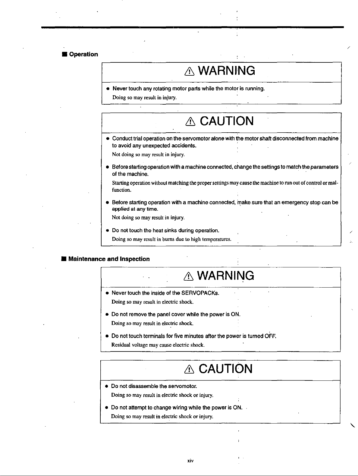
• Operation
/
& WARNING
• Maintenance
• Never touch any rotating
Doing so
may
result
in
motor
injury.
parts while the motor is running.
& CAUTION
• Conduct trial operation on
to
avoid any unexpected accidents. .
Not
doing
so
may
result
• Before starting operation with a machine connected, change the settings
of the machine.
Starting
function.
• Before starting operation with a machine connected,
applied at any time.
Not
•
Do
Doing
and
operation
doing
so
may
not
touch
the
so
may
result
Inspection
without
result
heat
in
bums
the
servomotor alone with the motor shaft disconnected from machine
in
injury.
matching
in
injury.
sinks
during
due
the
operation.
to
high
proper
settings
temperatures
may
.
cause
",ake
the
machine
sure that
an
to
match
the
parameters
to
run
out
of
control
or
emergency stop can
mal-
be
& WARNING
• Never touch the inside of
Doing
so
may
result
• Do not remove the panel cover while the power is ON.
Doing
so
may
result
• Do not touch terminals for five minutes after the power is turned OFF.
Residual
voltage
may
in
electric
in
electric
cause
the
SERVOPACKs.
shock.
shock.
electric
shock.
& CAUTION
• Do not disassemble the servomotor.
Doing so
• Do not attempt to change wiring while the power is ON.
Doing
so
may
may
result
result
in
electric shock
in
ele~tric
shock
or
or
injury.
injury.
xiv
Page 15
• General Precautions
Safety Precautions
Note
•
The
drawings
guards. Always replace the cover or protective guard as specified first, and then operate the
products
• The drawings presented in this manual are typical examples and may not match the product you
received.
• This manual is subject to change due to product improvement, specification modification, and
manual improvement. When this manual is revised, the manual code is updated and the new
manual is published as a next edition. The edition number appears on the front and back covers.
•
If
tive or one
• Yaskawa will not take responsibility for the results
uct. Yaskawa shall not be liable for any damages or troubles resulting from unauthorized modifi-
cation.
in
accordance
the manual must
of
the offices listed on the back
the
following
presented
in
this
with
the
manual.
be
ordered due to loss or damage, inform your nearest Yaskawa representa·
manual
to
ensure
are
of
this manual.
safe
sometimes
of
unauthorized modifications
application.
shown
without
covers
or
protective
of
this prod-
/
xv
Page 16

/
Page 17

Checking Products and Part Names
This chapter describes the procedure for checking l:-II Series products and
NS3l
the
1.1
1.2
1.3
0 Unit upon delivery.
Checking
Product
Mounting
Products
Part
the
It
Names
NS310
also describes the names
on
Delivery
.........
..................
Unit
of
product parts.
.
.
1 - 2
1 - 4
1 - 5
/
I
·1
Page 18
Checking Products and Part Names
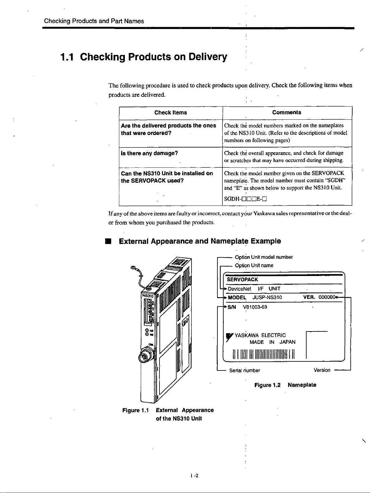
1.1 Checking Products
The
following procedure is used to
products are delivered.
on
Delivery
check
products upon delivery.
Check
the following items when
/
Check Items
Are the delivered products the ones
that were ordered?
Is
there any damage?
Can the
the SERVOPACK used?
If
any
of
er
from
NS310
Unit
be
the
above
items
are
faulty
whom
you purchased the products.
installed on
or
incorrect,
Check
the
model numbers marked on the nameplates
NS310
of the
numbers on following pages)
Check the overall appearance, and
or
scratches that may have occurred during shipping.
Check the
nameplate. The model number must contain
and
SGDH-DDDE-D
contact
model
"E"
~s
shown below to support
your Yaskawa
Comments
Unit.
(Refer to
number given
sales
• External Appearance and Nameplate Example
r--
pon
_
Opti~n
SERVOPACK
"OeviceNet
• MODEL
•
SIN
mmoenumer
Unit
name
I/F
JUSP-NS310
V81003·69
UNIT
the
descriptions of model
check
for damage
on
the
SERVOPACK
the
NS310
representative
VER.
00000
"SGDH"
Unit.
or
the
deal-
Figure
1.1
External Appearance
NS310
of the
Unit
1·2
"YASKAWA
111111111111111111111111111111111111
Senal
-
ELECTRIC
MADE
number
IN
JAPAN
Figure 1.2 Nameplate
I
Version
-
Page 19

• Model Number
NS310 Unit
1.1
JUSP - NS31 0
Checking
Products
on
Delivery
SERVOPACK
Type
NS31:
peripheral device
01
device:
DeviceNet
Interface
~
Unit
~
L
Design
Revision Order
/
1·3
Page 20

Checking Products and Part Names
1.2 Product Part Names
The following diagram illustrates the part names of theNS310 Unit.
Ground
wire:
Conect
to
SERVOPACK.
the
terminal
ma'rked
"G~
on
the
~
SGDH
'L_-
Rotary switches
Used
to
Rotary Switch (SW3):
Used
to
set
set
(SWt,
the
DeviceNet
the
baud
SW2):
rate
node
for
DeviceNet.
address.
"6iMtl-l--- Connector for RS-232C communications (CN11):
Used
to
communicate
LEO
(MS):
Module
LED (NS): Network Status LED indicator
Connector
Micro
for
Connector
with
Status
DeyiceNet
for
DeviceNet
the
NSxxx
Setup
LED
indicator
communications
Communications.
Tool.
(eN6):
Figure 1.3 NS310 Unit
1-4
Page 21
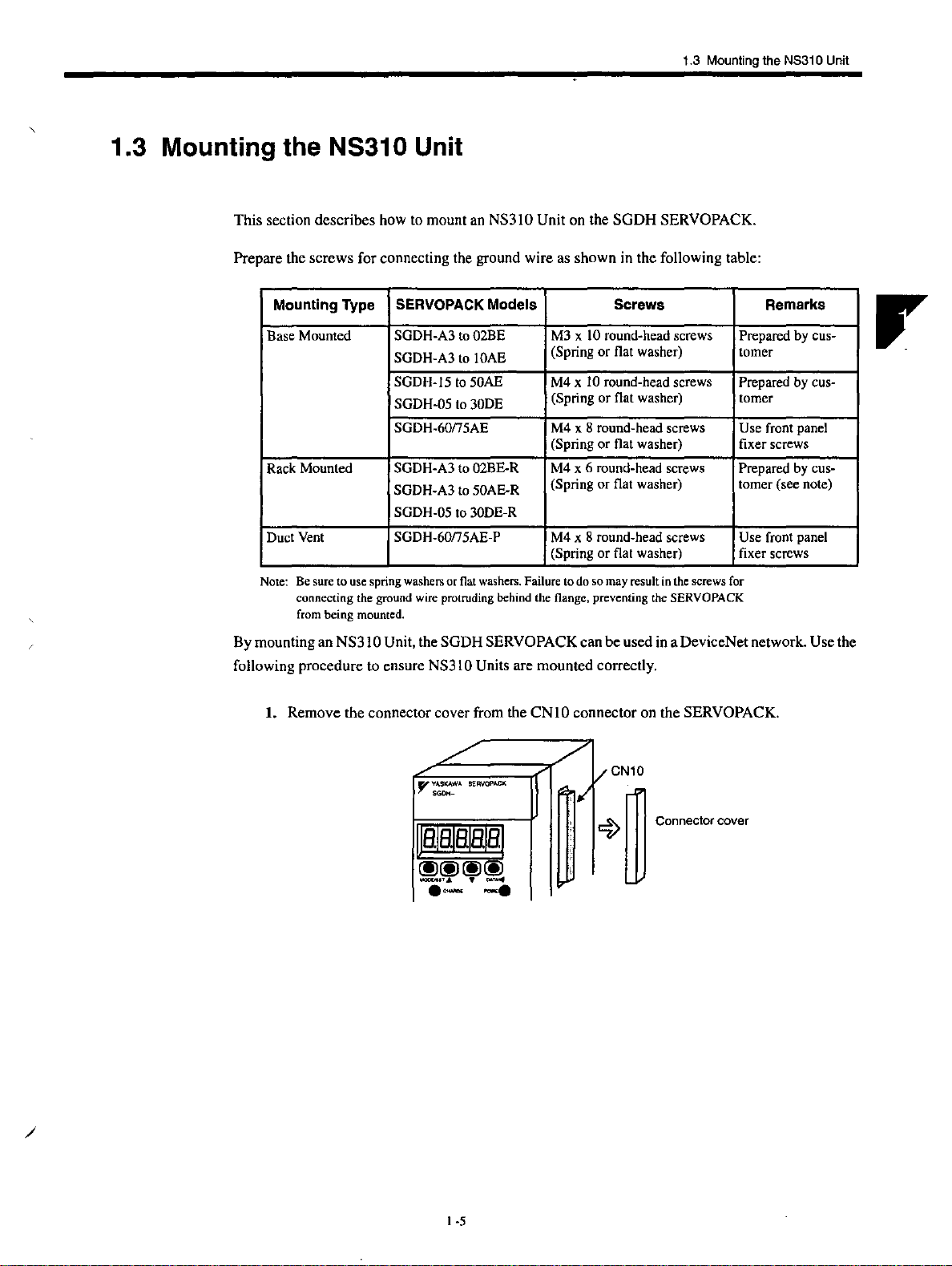
1.3 Mounting the NS310 Unit
1.3 Mounting the NS31 0 Unit
This section
Prepare the
describes
screws
Mounting Type SERVOPACK Models Screws Remarks
Base Mounted SGDH-A3
Rack
Mounted
Duct
Vent
how to mount an NS310 Unit on the
for connecting the ground wire as
to
02BE
SGDH-A3
SGDH-15
SGDH-05
to
to
to
lOAE
50AE
30DE
SGDH-60mAE
M3 x 10
(Spring or flat washer)
M4 x 10
(Spring or flat washer) torner
M4
(Spring
SGDH-A3
SGDH-A3
SGDH-05
SGDH-60mAE-p
to
02BE-R
to
50AE-R
to
30DE-R
M4
(Spring
M4
SOOH
shown
in the following table:
round-head
round-head
x 8
round-head
or
flat
washer)
x 6
round-head
or
flat
washer)
x 8
round-head
SERVOPACK.
screws
screws
screws
screws
Prepared by cus-
temer (see note)
screws Use
(Spring or flat washer)
Note:
Be
sure
to
use
spring
washers
or
flat
washers.
Failure
to
do
so
may
result
in
the
screws
for
By
mounting an
following
connecting
from
procedure
the
ground
wire
being
mounted.
NS310
Unit, the
SODH
to ensure NS310 Units are
protruding
behind
SERVOPACK can
the
flange. preventing
mounted
the
SERVOPACK
be
used in a DeviceNet network. Use the
correctly.
Prepared
by
ellS-
tomer
Prepared by cus-
Use
front
panel
fixer screws
front
panel
fixer
screws
1.
Remove
the connector cover from the
CNIO
connector on the SERVOPACK.
/
t
-5
Page 22

Checking Products
a,nd
Part Names
2.
Mount the NS310 Unit on the SERVOPACK.
SERVO
.,.,--.
7
SGDH-
PACK
Connector
I
o.
o.
/
-
3.
For grounding, connect a ground wire
SERVOPACK.
~alBJaalal
~~~~
~
. .
""
'"
POM.'.
30 W to
-<3"
~_
Illi"lIIlD
l/JJ
...
For
SERVOPACK
./
·,.Y~~
•
__
~
-.
of
5.0
kW
"
\//
~
a
Cl!;l!;lCl1l
0
, '
the NS31 0 Unit to the point marked
"""\JIIiI,,/
'-"'"
~
,.",-
Ground
.
wire
-%
"G"
on the
For
SERVOPACK
1-6
6.0
kW
to
7.5
kW
Page 23

1.3
Mounting
the
NS31 0 Unit
When the
in
NS31
the
following diagram.
0 Unit
has
been
mounted correctly. the SERVOPACK will appear
as
shown
/
1
-7
Page 24

Page 25

Installation
This chapter describes precautions for
The
SODH SERVOPACKs are base-mounted servo amplifiers. Incorrect
installation will cause problems. Always observe the installation precautions shown in this chapter.
2.1
Storage
2.2
Installation
2.3
Orientation
Installation
2.4
Conditions
Site
.......................
...........................
...........................
~I1
Series product installation.
...................
2-2
.
2-2
.
2-3
.
2-4
.
/
2
-I
Page 26
Installation
2.1
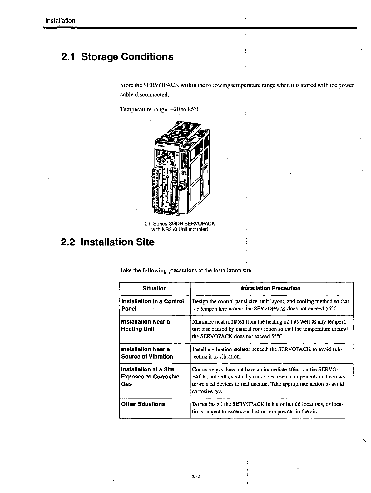
Storage
Conditions
Store the SERVOPACK within the following temperature range when it is stored with the power
cable disconnected.
Temperature range:
l:-II Series SGDH SERVOPACK
with
-20
NS310
to 85°C
Unit
mounted
2.2 Installation Site
Take the following precautions at the installation site.
Situation
Installation In a Control
Panel
Installation Near a Minimize heat radiated from the heating unit as well as any tempera-
Heating Unit
Installation Near a
Source
Installation at a Site Corrosive gas does not have an immediate effect
Exposed
Gas
Other Situations
of
Vibration jeeting
to
Corrosive
Installation Precaution
Design the control panel size. unit layout, and cooling method so that
the temperature around
ture
ris~
caused by natural convection so that the temperature around
the SERVOPACK does not exceed 55
Install a vibration isolator beneath the SERVOPACK to avoid sub-
it
to vibration.
PACK, but will eventually cause electronic components and contactor-related devices to malfunction. Take appropriate action to avoid
corrosive gas.
Do not install the SERVOPACK in hot or humid locations,
tions subject to
the
SERVOPACK does not exceed 55°C.
excessiv~
dust
or
'C.
on
the SERVO·
iron powder in the air.
or
loca-
2-2
Page 27

2.3 Orientation
2.3
Orientation
Install the SERVOPACK perpendicular to the wall as shown in the figure.
must
be
oriented this way because it is designed to be cooled by natural convectiori
fan.
Secure the SERVOPACK using2 to 4 mounting holes.
VOPACK
capacity.
The
number
of
holes depends
t t
Wall
Ventilation
The
SERVOPACK
on
or
cooling
the SER-
r
/
2 ·3
Page 28

Installation
2.4 Installation
Follow the procedure below to install multiple SERVOPACKs side by side in a control panel.
50 mm (1.97 in) min.
30 mm (1.18 in) min. 10 mm (0.39 in) min.
50 mm (1.97 in) min.
• SERVOPACK Orientation
Install the SERVOPACK perpendicularto the wall so that the front panel (containing connectors)
faces outward.
• COOling
As shown in the figure above, provide sufficient
by
cooling
fans
or
natural
convection.
sp~ce
around each SERVOPACK for cooling
• Side-by-side Installation
When installing SERVOPACKs side by side as shown in the figure above, provide
(0.39 in) between and at least
ing fans above the
perature inside the control panel.
SERVOPACKs to avoid excessive temperature rise and to maintain even tem-
• Environmental Conditions in the
50
mm
(1.97 in) above and below each SERVOPACK. Install cool-
CO!'!trol
Panel
at
least 10
mm
Oto
• Ambient Temperature:
Humidity:
•
• Vibration:
• Condensation and Freezing: None
• Ambient Temperature for Long-tenn Reliability;
2-4
55°C
90% or less
2
4.9mJs
max.
45°C
Page 29
•
jM
fiii*5MMW
fipM;
#
""*EM
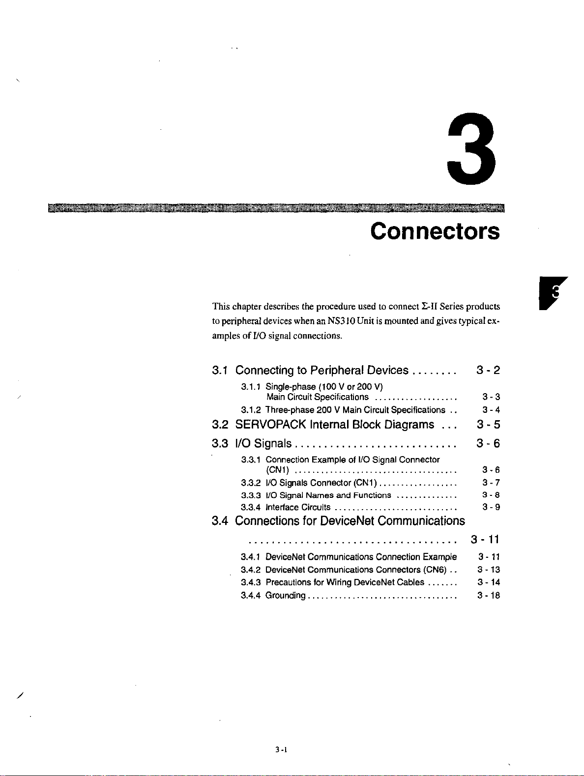
Connectors
This chapter describes the procedure used to connect I:-II Series products
to peripheral devices when an
amples
3.1
of
I/O signal connections.
Connecting to Peripheral Devices
3.1.1 Single-phase (100 V or 200
Main Circuit Specifications
3.1.2 Three-phase
3.2 SERVOPACK Internal Block Diagrams
3.3
110
Signals
3.3.1 Connection Example of I/O Signal Connector
I/O Signals Connector (CN1)
3.3.2
3.3.3
110
3.3.4 Interface Circuits
...........................
(CN1)
....................................
Signal
3.4 Connections for DeviceNet Communications
NS310 Unit
is
mounted and gives typical ex-
.......
V)
..................
200 V Main Circuit Specifications
.................
Names
and Functions
..........
. . . . . . . . . . . . . . . . . . 3 - 9
..............
..
.
.
..
.
.
.
.
3-2
3-3
3-4
3-5
3-6
3-6
3-7
3 - 8
3 -
11
3.4.1 DeviceNet Communications Conneclion Example
3.4.2 DeviceNet Communications Connectors (CN6)
3.4.3 Precautions for Wiring DeviceNet Cables
3.4.4 Grounding
/
3 -I
.................................
......
..
3 -
11
3
-13
.
3 - 14
.
3 - 18
Page 30

Connectors
·3.1
Connecting to Peripheral Devices
This section provides examples
It
also briefly explains how to connect each peripheral device.
of
standard
1:-11
Series product connections to peripheral devices.
3 -2
Page 31

3.1
Connecting to Peripheral Devices
3.1.1
Molded-case Circuit
Breaker
00
Single-phase (100 V
(MCCB)
P<otect,
th,
line
by
overcurrent
detected.
pow·
shuttIng
OFF
er
o the circuit
When
is
&1
Noise
Filter
Used
to eliminate external noise
Irom the power line.
or
Power
supply
Single-phase 200
R • T
""[I;IJ'IPIV
200
VAC
,
,
I
:
I
I
I
I
I
I
I
I
V)
Main Circuit Specifications
Can
Host
be connected to
~mlffi
MEMOCON
(Manufactured by
Digital Operator (See note.)
~~~;n
Personal Computer (See note.)
,
,
,
,
,
,
,
,
,
,
,
GL1201130,
Yaskawa)
DeviceNet
Master.
MP920
JUSP·QP02A·2
Allows
the
user
parameters
tion
display operation or
alarm
Communication
possible
al
computer.
or
references
status.
with a person-
to
opera-
and
is
set
to
also
~
Cable model:
Magnetic Contactor
HI
S'""
Turns
the
servo
ON
and
OFF.
fIj
Power Supply for Brake
Used
brake.
/
Install a surge
suppressor
magnetic conlac-
tor.
lor a servomotor
on
tna
with
a
I I
,---
--- ---
Regenerative Resistor
Connect
-:
to
capacity
:;~~:~::'~;:':t.:~".:,::;:::;::
terminals
81
and
is
insuflicienl.
---:----
---
Regenerative
- _ (option)
resistor
--
--
--- ---
---
Note Used for maintenance. Be sure to coordinate
operation from these devices with controls exerted
by the host controller.
JZSP-CMS01
Encoder
Cable
Encoder
Connector
to 03
3 ·3
Page 32

Connectors
3.1.2 Three-phase 200 V Main Circuit Specifications
3.1.2 Three-phase 200 V Main Circuit Specifications
Breaker (MCCB)
o the circuit
00
Circuit
P,otect, the
9f
line
by
when
overcurrent
is
detected.
pow-
shutting
OFF
r!J
Noise Filter
Used
to
eliminate external
from the power line.
Magnetic Contactor
noise
Noise
Power supply
Three-phase
filter
0
Host
: Controller
Can be connected
to
DeviceNet Master.
~el~o~ij~,U1
MEMOCON
,
,
,
,
,
,
,
200
VAC
T
,
,
,
,
,
,
,
,
..
I
I
I
I
I
I
I
I
(Manufactured
Digital
Personal
Cable model: JZSP·CMS01
Gl1201130, MP920
by
Operator
JUSP·OP02A·2
Allows
parameters or operation references and
display operallon
alarm status .
Communication is
posSible with
al
computer.
Computer
Yaskawa)
(See note.)
the
user
(See
-s
to
03
to
set
to
or
a
~~::::
ON
;'";,'~ta;;It,-;;;;
IJ
Power Su'pply
Used for a
brake.
If
the
capacity
the
tive
For SERVQPACKs
eldemal
and
SERVOPACKs.)
of
wire
between
resistor
to
terminals 81 and
regenerative resistor between terminals
82. (There
is
to'
servomotor
the internal regenerative resistor
tanninsls
82
with
a capacity
no
terminal 83
seriO
and
OFF
~~
II,.
I
for
Brake
with a
II
1:_----_
is
kW
or
higher,
Bl
insufficient,
and
83
and connect an external regenera-
82.
of
6.0
on
these '
----
connect
remove
---
--
. Encoder
Cable
Encoder
Connector
--
--
-- --
--
Note U sed for maintenance. Be sure to coordinate
--
--
---
operation from these devices with controls
by the host controller.
exerted
3-4
Page 33

3.2 SERVOPACK Internal Block Diagrams
The
following sections show an internal block diagram for the SERVOPACK with an NS3 10 Unit.
30 to 400 W 200·V and 30 to 200 W 100·V Models
Single-phase
200
to
230
v:;:
(5ot60Hz)
~--
...,.,
'"
3.2 SERVOPACK Internal Block Diagrams
AC
servomotor
~r;~I~~~~~'~
L.. _ _ Open
(iII'l
D'
, ,
'"------------------------.
during
servo
alarm
Master node
24·V
communications
power
supply
'!'
0------------
,
,
,
.w
,
,
,
...
"N
,
ASIC
(PWM control)
,
I
,
I
,
I
,
L
__
_
Analog
momlor
output
,..-_
,
I
,
I
,
I
,
I
,
L
! I
for
....!:e~sion
DeviceNet
communications
DC to DC
converter
____________________________
-c~~~:~:c::::::f=::::::::~;~:'~'-
::
Digital Operator!
su-
personal
_________
interface
computer
CPU
(position
calculations)
and
speed
--c===;:=====;;!;-
CPU
(position
command
arithmetic
etc.)
commands,
interpretation,
processing,
~,
--'
51Mb"
...
Saud
...
No.
Sequence
va
!.
.
/
3
-S
Page 34

Connectors
3.3.1
Connection Example of
3.3 1/0 Signals
110
Signal Connector (CN1)
This section describes 110 signals for the SERVOPACK with the NS3l 0 Unit.
3.3.1
Connection Example of
The following diagram shows a typical example
Backup
batte~
2.8
to
4.5
V·
+24
Not
used
Forward run prohibited
(Prohibited when OFF)
Reverse run prohibited
(Prohibited when OFF)
Not
used
Home position
Emergency
signal
stop signal
1/0
Signal Coimector (CN1)
of
110
signal connections.
SGDH
SERVOPACK
CNI
BAT
~'--'Tr:
::r
V"'l
~~
+
IP----,+'21
~BAT
-
+24VIN 47
~~-}---~~:::-~
__
~4~1~_~
40
22
3.3kQ
:+-~~1
__
:~t_:~\i
~~~P~-o~T!-,f4~2~_+-_-4:~t_:~{j
I-o~
ZERO
EMSTOP
'-<"";==:::"'F~----i":-!..
*
1.
:P
*
2.
When using an absolute encoder, connect a backup battery only
battery connected to the eNS.
* .3. Make signal allocations using parameters. (Refer to 6.1.2 Standard
CNI/IO
45
~
46
represents twisted-pair wires.
Signals.)
-(";'Ji
:-t
.....
~:
____
'
r1
-::!:-
I
Connector
FG
Connect the shield wire to connector
~_..::c.
<-
.
rt---':~
,<-
.Jrt---':~,AL03
""--~...l..jI
,,'l-":')'~
~:'--'=::'f
It
....
~
i
"____
'r.-_-,2C(.7."
11-:';J:
,f~~i
"----!,i--~2~9."/BK-
:1~~·r.
!:--'£f/
~"!:-:.
_1,;'
__
:1-:~r.
~,--"-.L~ALM+
It-:~:
L_~_~'
__
shell
..
ALOI Alarm code output
37
38
39'
25
26
28
"-30".,,
31
,,"32".fALM-
}
AL02 voltage: 30 VDC
SG
ICOIN+
ICOIN- been completed)
IBK+
S-RDY
I5-RDY-
whcm
Maximum operating
Maximum operating
current: 20
Positioning
(ON when positioning has
Brake output
(ON when brake released)
Servo ready output
+
(ON when ready)
Servo alarm output
(OFF for an alarm)
PhotocQupler output
Maximum
voltage: 30 VDC
Maximum operating
current: 50 rnA DC
shell.
there is
no
Setti~gsfor
rnA
DC
completed
'3
operating
Figure
3.1
110
Signal Connections
3-6
for
CN1
Connectors
Page 35

3.3 1/0 Signals
2
4
6
8
10
12
14
16
18
20
22
24
3.3.2
SO
- -
SO
SO
- -
-
-
-
-
BATH
-
1/0
Signals Connector (CN1)
The following diagram shows the layout
•
CN1
Terminal Layout
I SO
aND
3
5
aND
7
aND
-
-
9
II
13
15
17
-
19
-
BAT (+)
21
Battery H 47 +24VIN
23
-
25
ICOIN+
aND
- -
- -
- -
- -
-
-
- -
Battery (+)
-
Positioning
complete
output
27
29 IS-RDY+
31
33
35
37 ALOI
-
39 AL03
41
-
43
45 ZERO
49
of
IBK+
(Note 3)
ALM+
- -
N-OT
-
eN I terminals.
Brake
inter-
lock
output
Servo
ready
output
Servo
alarm
output
Alarm code
output
(open-eollee-
tor output)
Reverse
prohibited
input
Home
tion
External
power supply
input
run
pasi-
signal
-
Positioning
26 leDlN- complete
output
IBK-
28
(Note 3)
IS-RDY-
30
32 ALM-
34
36
38 AL02
40
Brake
lock output
Servo
output
Servo
output
- -
Alann
output
inter-
ready
alann
code
Forward
P-OT
42
44
46
48
50
EMSTOP
prohibited
input
- -
Emergency
stop signal
- -
drive
Note
1.
Do
not use unused tenninals for relays.
2.
Connect
the
shield
of
the
110
signal
cable
to
the
3.
The
Make
shield
signal
is
connected
allocations
to
the
using
FG
(frame
parameters.
ground)
(Refer
connector
to
shell.
at
the
SERVOPACK-end
6.1.2 Standard Settings
connector.
for
CN1/IO
Signals.)
• CN1 Specifications
Specifications for Applicable
SERVOPACK
/
Connectors
1 0250·52A2J L 50·p
Right
Angle
Plug
Soldered
10
I 50-3000VE
3
-7
10350-52AO-OO8
Receptacles
Case
Manufacturer
Sumitomo 3M Ltd.
Page 36

Connectors
3.3.3 I/O Signal Names and Functions
3.3.3 1/0 Signal Names and Functions
The following section describes SERVOPACK 110 signal names and functions.
• Input Signals
Signal Name
Common
P·OT
N·OT
ZERO
EMSTOP
+24VIN
BAT (+)
BAT
Signal Name Pin
Common
ALM+
ALM-
IBK+
IBKIS·ROY+
IS·ROY-
AL01
AL02
AL03
FG
Position ICOIN+
ICOIN-
Note
1.
Pin numbers in parenthesis 0 indicate signal grounds.
2.
The functions allocated
signals can be changed to feLT.
Pin No.
42
Forward run prohibited I Overtravel prohibited; Stops servomotor
43
Reverse run prohibited beyond the allowable range of motion.
45
External latch signals for home position
46
External signal for emergency stop connected.
47
Control
Allowable voltage fluctuation range:
21
Connecting pin
(-)
22
Connect to either eN8
• Output Signals
No.
31
Servo
32
27
Brake interlock: Output that controls the brake.
28
29
Servo ready: Turns
30
37
Alarm code output: Outputs 3-bit alarm codes.
38
Open-collector:
39
(I)
Shell
to
Connected to frame ground
nector shell.
Positioning completed (output in Position Control Mode):
25
26
error pulses reaches the set value. The setting is
units (input pulse units defined by the electronic' gear).
IBK. IS-ROY. and ICOIN can
NLT,
ffGON,IWARN, or INEAR signals.
Func!ion
when
movable part travels
connect~d.
power
supply input for sequence signals: Users must provide the +24-V power sup-
ply.
11
to 25 V :
for
alarm:
the absolute encoder backup
or
eNI.
Turns OFF
ply
30
when
an
ON
if
there is no servo alarm when the controVrnain circuit
is
turned
ON.
V and
20
rnA rating maximum
if
the shield wire
be
changed via parameters.
error is detected.
battery.
Function
I
I
The
brake is released when this signal is ON.
of
the 110 signal
~he
number
The~K./S-ROY.
cable
1ums
of
error
and ICOIN output
-
is connected to the con-
ON
when
pulses set
the
power
number
in
reference
sup-
of
·8
3
Page 37

3.3.4 Interface Circuits
The
following diagram shows an example
signal
for
a SERVOPACK.
• Sequence Input Circuit Interface
3.3 1/0 Signals
of
connections between a host controller and the 110
The sequence
input
circuit
interface
connects
through a re1ay
Select a low-current relay, otherwise a faulty contact will result.
SERVOPACK SERVOPACK
24VDC 24VDC
50 rnA min.
+ 0
.24VI.
IDEC,
etc.
3.3
kG
i -
li
-~;fl
___
~.
• Output Circuit Interfaces
Any
of
the following three types
circuit at the host controller that matches one
• Connecting to an Open-collector Output Circuit
Alarm code signals are output from open-collector transistor output circuits.
Connect an open-collector output circuit through a photocoupler, relay, or line receiver cir-
cuit.
510
SERVOPACK
end
or----<~ri-_....J
r:I~
12VDC
Pholocoupler
of
SERVOPACK output circuits can be used. Form an input
of
these types .
SERVOPACK
end
so
mA
or
open-collector
min.
3.3kD:
51024
VDC
C~
transistor
Relay
circuit.
OV
5to12VOC
SERVOPACK
end
/
:
•....
3 -9
OV
Note
The
maximum
ties
for
·Voltage:
·Current:
allowable voltage
open-collector
30
VDC
max.
20
rnA
DC
output
max.
and
circuits
current
are
as
capaci-
follows:
Page 38

Connectors
3.3.4
Interface
Circuits
• Connecting to a Photocoupler Output Circuit
Photocoupler
output
circuits
are
used
for
servo
:alann,
servo
ready.
and
other
put signal circuits.
Connect a "hotocoupler output circuit through a relay or line receiver circuit.
5
to
24
voe
SERVOPACK
end
Relay
C-~
.SERVOPACK
end
,'
.....
51012VDC
ov
Note
The
maximum
circuits
.
Voltage:
-Current:
allowable voltage
are
as
follows:
30
VDC
50
rnA
DC
max.
max.
and
current
capacities
for
photocoupler
output
sequence
ov
out-
, .
3 -10
Page 39

3.4
Connections
for
DeviceNet
3.4 Connections for DeviceNet Communications
Communications
This section describes the connection and wiring
of
connectors for
DeviceNet
3.4.1 DeviceNet Communications Connection Example
The following diagram shows an example
NS3IO Unit (CN6) using DeviceNet communications cables.
T-Branch
(with
Adapter
terminator)
T
of
connections between a host controller
T
:
:
T : T·Branch Adapter
communications.
Terminator
Trunk
line
Drop
line
and
an
Figure
3.2
Network
Connections
• Configuration Elements
The network is configured from the following elements.
Nodes
A node is either a slave that connects
ages the
110
of
the slaves. There are no restrictions on the location
node in Figure 3.2 can be the Master or a slave.
to
an NS31 0 Unit or similar Unit, or the Master that man-
of
the Master or slaves.
Any
Trunk Line and Drop Lines
A cable with a terminator on each end is a trunk line. Any cable branching from the trunk line
is a drop line.
Connection Methods
A node is connected using the T-branch method
/
used to connect a node with the T-branch method. A node is directly connected to the trunk line
or
a drop line with the multi-drop method. Both T·branch and multi·drop methods
together in the same network, as shown in
or
multi-drop method. A T-Branch Adapter is
Figure 3.2.
can
be used
3
·11
Page 40

Connectors
3.4.1
DeviceNet
Communications
Terminator
Connection
Example
I
IMPORTANT
Both ends
and ensure stable network communications.
of
the trunk line must connect to terminating resistance to decrease signal reflection
Communications Power Supply
I
The communications connector
supply through the communications cable for DeviceNet communications.
1.
The
2.
3.
Both
Only
lightning
communications
ends
of
DeviceNet devices
arrester.
the
cable
trunk:
line
must
must
can
be a special
connect
be
connected
of
each node must
• Branching from the Trunk Line
There are three methods that can be used to branch from the trunk line.
Single Branching
Trunk
line
Trunk
line
DeviceNet
to a terminator.
to
the
network.
'be
provided with a communications power
cable.
Do
not
connect
any
other
devices,
such
as
a
T·Branch
Adapter
Branching to Three Drop Lines
Direct Node Connection
Trunk
line
-'-;1
Multi-drop
Trunk
line'
:;::~~~7~10~1
;;;.;;
methOd
• Branching from Drop Lines
There are three methods that can be used to branch
3
-12
~om
,
drop lines.
Page 41

Single Branching
Drop
line
Drop
T-Branch Adapter
3.4 Connections for DeviceNet Communications
line
Branching
to
Three Drop Lines
Direct Node Connection
Drop line
Drop
line
3.4.2 DeviceNet Communications Connectors (CN6)
The terminal layout and specifications
of
the CN6 connectors are shown below.
• Connector Specifications
The
following table
a flange attached.
Unit side DeviceNet-compatible
Cable side DeviceNet-compatible
/
shows
the
connector
Name
Micro-style Connector
(male)
Micro-style Connector
(female)
3
-13
specifications.
These
connectors
Model Manufacturer
CM02-8DR5P
Not specified. Not specified.
are metal plated
DDK
with
Page 42

Connectors
3.4.2
DeviceNet
Communications
• Connector Pin Arrangement
Connectors
The
connector
(eNS)
pin
arrangement
is
as
shown
below.;
Pin No.
and
Code
I SHIELD
2
3
4
5
SHIELD
Symbol
24
V 24 V
0(24
V)
CANH
CANL
CANH
,
Connect
o V
CAN bus line dominant H
CAN
to
external
extem~
bus
line
CANL
'the
wire
mesh
communications
communications
dominant
L
OV
Detail
around
power
the
power
cable.
supply
supply
3 ·14
Page 43

3.4
Connections
for
DeviceNet Communications
3.4.3 Precautions
Observe the following precautions when wiring DeviceNet cables.
• Maximum Network Length
The
maximum network length is either the line length between two nodes located farthest from
each other
longer.
IE
T·Branch Adapter
(with
terminator)
for
Wiring DeviceNet Cables
or
the line length between the terminators on the ends
~
The longer of the two distances is the maximum network length .
• 0
T
T
of
the trunk line, whichever is
~
Terminator
: Trunk line
: Drop
line
T :
T-Branch
Adapter
Special DeviceNet cables can be either thick cables or thin cables. The characteristics
of
each
type are given in the following table.
Item
Thick
Signal
decay
Communications
distance
Characteristics
The
maximum network length is determined by the type
Baud
rate
(Kbps)
Slight
Long
distance Short distance
Rigid (difficult
Maximum
Thick
500
250
125
/
100
250
500
Cable
to
cable
Cable
bend)
network
Type
Thin
Cable
Considerable
Pliable (bends easily)
of
cable, as shown in the following table.
length (m)
Thin
cable
100
100
100
3
-15
Page 44

Connectors
3.4.3
Precautions
(')INFO
for
Wiring
DeviceNet
The
I>
the
Baud Rate (Kbps) Maximum Network Length (m)
line
length
250
Note
Cables
connecting
of
each
500
125
LTHICK:
two
nodes
located
farthest
cable
satisfies
LTHICK + LTHIN
LTHICK
LTHICK + 5.0 X LTHIN S 500
Thick
the
conditions
+ 2.5 x
LTHIN
cable length
;;;
100
LTHIN:
• Drop Line Length
The
drop line length is the line lenglh between a branch point on the trunk line to iIle farthest node
Ihat is located on the drop line.
out
into
other
drop
lines.
The
maximum
from
each
othe~
in
the
following
;;;
250
Thin cable lenglh
drop
can
use
both
thick
table.
line lenglh is 6 m. A
and
drop
thin
cables
line
provided
can
be branched
that
• Total Drop Line Length
The
total drop line length is a total
of
all drop line lengths.
Length Limits
The total drop line length
be 6 m or less.
The
allowable range
table.
Baud Rate (Kbps) Total Drop Line Length (m)
500
250
125
39
78
156
oftolal
max.
max.
max.
must
be within the allowable range and even Ihen,
drop
line lenglh varies with Ihe baud rate as
each
shown
drop
line must
in
Ihe following
3 -16
Page 45

3.4
Connections
for
DeviceNet
Communications
TMBranch
(with
terminator)
The following example is for a baud rate
Adapter
T
T
of
500
Kbps.
~f
·1
g~
The above example must satisfy the following conditions .
•
b~6m
.c~6m
T
~h
T :
:
Trunk
Drop
T-Branch
Terminator
line
line
Adapter
·d~6m
•
d+f ~ 6m
• d+e+g ~ 6m
• d+e+h ~ 6m
The total drop line length must satisfy the following condition.
• Total drop line length = a+b+c+d+e+f+g+h ~ 39 m
• Basic Precautions
Basic precautions
o
The
• The communications power supply must have a sufficient margin
o Connect the communications power supply to the trunk line.
o
If
many nodes are provided with power from a single power supply, locate the
supply as close as possible to the middle
o
The
o
The
a drop line is, the
of
/
the allowable current consumption
following equation.
are
as follows:
communications power supply to the network must be
of
the trunk line.
ali ow able current flow in a thick cable is 8 A and that in a thin cable is 3 A.
power supply capacity for a drop line varies with the drop line length.
the thickness
lowerthe
of
the drop line. Obtain the aliowable current (I)
maximum current capacity
of
the drop line and devices connected to it) from the
24
VDC.
in
the capacity.
The
of
the drop line will be regardless
of
the
drop
power
longer
line (i.e.,
3
-17
Page 46

Connectors
3.4.3
Precautions
for
Wiring
DeviceNet
Cables
•
The
1=4.S7/L
•
If
only the communications
errors
. - ,
Location
following two types
6f
may
occur
Power Supply
I:
Allowable current (A)
L:
Drop line length
power
supply is turned
in
the
nodes
that
are
communicating
of
configuration are possible for the location
Nodes on-Both Sides of the Power Supply
Nodes
Power Supply
T-Branch
Communications
power
on
One Side of the Power Supply
Tap
Adapter
supply
or
,
(m)
OFF
while the network is operating,
at
that
time.
of
the
power
supply.
Note
Power
Supply
T·Branch
Communications
power
supply
The
"Nodes
on
er
supply
is
connected
Tap
Adapter
Both
Sides
or
to
of the
many
Power
nodes.
Supply"
method
is
recommended
if a
single
pow-
3 -18
Page 47

3.4.4 Grounding
3.4
Connections
for
DeviceNet
Communications
As shown below. connect the shield wire
of
the cable to the
power supply and ground the shield wire to a resistance
• Power Supply with Single-point Ground
T-Branch
Adapter
"\
-
'--
-=-
or
Power
Supply
Tap
CANH
v+
}
Shield
CANL
v-
FG
~ommunications
power
Ground
to a resistance
v+
supply
v
of
100 n
CommunicaUon
cable
or
less.
• Power Supply without Ground
Power Supply Tap
of
FG
terminal
100 n
or
of
the communications
less.
CANH . .
v+
}
Shield
Communications
CAN
L
cable
v-
n
FG
Communications
power
- -
-=-
Ground
to a resistance
If
more than one communications power supply is used, ground only the power supply that is
located closest to the middle
supply through the shield wire at any
is connected to the network, connect them using a
1.
Power
Ground
Do
not
Do
not
supplies
ground
I IMPORTANT I
2.
3.
/
4.
the
network
ground
are
the
the
network
network
v-
v+
supply
not
counted
to a resistance
together
through
of
100 n or
of
the network through the shield wire. Do not ground the
less.
otherpoint.lfmore
than one communications power supply
Power Supply Tap each.
as
nodes.
of
100.0:
or
less.
with
the
shield
servodrivers
wire
at
or
.more
inverters.
than
one
point;
ground
at
a single
point
power
only.
3 -19
Page 48

Page 49

Parameter Settings
This chapter explains the outline and details
4.1
Parameter
4.1.1
4.1.2
4.1.3 Editing
4.1.4 Effective TIming
4.2
Parameters
4.2.1
4.2.2 Homing
4.2.3 Machine System and
4.2.4 Speed, Acceleration, and Deceleration Parameters
4.2.5 Positioning Parameters
4.3
Parameter
4.3.1
4.32
4.3.3 Machine System and
4.3.4 Speed, Acceleration, and Deceleration Parameters 4 - 24
Outline
What Are Parameters?
Parameter Types
Parameters
Tables
Unit Parameters
Parameters
Peripheral Device Parameters
Details
Unit Parameters
Homing Parameters
Peripheral Device Parameters
....................
...........................
........................
............................
.....
...........................
........................
....................
........................
of
NS31 0 parameters.
......................
...............
.....................
:.
.
4-2
.
4-2
4-2
.
4-3
4-4
.
.
4-5
.
4-5
.
4-5
4-7
4-8
.
4 - 10
.
4 -
11
4 -11
.
4 -
14
4 - 18
4.3.5
Positioning Parameters
/
4 -I
......................
4 - 35
Page 50

Parameter Settings
4.1.2
Parameter
Types
4.1
Parameter Outline
4.1.1 What Are Parameters?
Parameters
the NS3 10 Unit. You
and the machine to which the
You can edit the
or host controller.
For
SGDH
Maintenance (SIE-S800-32.2).
is
parameters, refer to Chapter 6 Parameters
4.1.2 Parameter Types
Parameters are classified depending
•
Unit
parameters
the
name
given
to
user
constants
must
set the
optimum
SGDH is mounted.
NS3 10 Unit parameters using the NSxxx Setup Tool,
For
the NXxxx Setup Tool. refer to Chapter 7 Using the NSxxx Setup Tool.
on
their purpose as follows:
th~t
are
required
valueSfor parameters according to the NS3 10 Unit
or
the SCDH User s Manual Design and
as
the
settings
DeviceNet
used
to
operate
Configurator,
• Homing parameters
• Machine system
• Speed, acceleration, and deceleration parameters
• Positioning
Parameters are further classified according to the priority
Table
4.1 Parameter
Type
A
S
C
and
peripheral
paramete~s
Types
Parameters
Parameters
Parameters
that
must
l,hat
must
whose
settings
device
be
set
be
set
parameters
even
when
when
using
hardly
ever
Meaning
using
the
need
of
the setting, as shown below.
the
NS310
Unit
in
standard
NS31 0 Unit
to
be
in
changed.
special
mode.
mode.
4-2
Page 51

4.1.3 Editing Parameters
You can edit parameters using the following methods.
4.1
Parameter Outline
I
IMPORTANT
Table 4.2
Methods
Tools
NSxxx Setup Tool
Select
read
tef the parameters have been displayed, power is turned
select the parameters you want to edit,
and click the
rameters.
Master Device
Configurator
If
parameters are changed via DeviceNet, they
I
Trajectory Command is executed.
automatically written to the flash
or
You
(Sel_Attrihule_Sing/e)
Device.
Object
Ox25
of
Editing
Parameters
Methods
Remarks
Ust From the Parameter Menu to All changed parameters are stored in
all
the
NS310
Unit
parameters.
Af-
RAM, so they are erased when the
OFF. Use the Module
Reset Command to write the parameter
Edit
Button to edit the pa- data
can edit using Explicit Message All changed parameters are stored in
from
the Master
wi1J
be automatically written to the flash ROM after the Start
To
lengthen the service life
ROM ·when the following parameters are changed.
of
the flash ROM, however, parameters are not
Attribute
6
7 Target Speed
Target
in
RAM
to
the
flash
ROM.
RAM.
Set
the Start Trajectory Bit
to write the parameter data in RAM to
the
flash
ROM.
Name
Position
to
I
Use
one
of
the
following
8
9 Deceleration
methods
when
it
is
Acceleration
necessary
to
be
sure
written to flash ROM.
Execute the Module Reset Command from the NSxxx Setup Tool.
•
• Execute the Reset Service to the Identity Object via DeviceNet.
Starting
positioning
and
other
movement
operations
will
not
be
automatically written to flash ROM.
that
all
delayed
parameters
when
parameters
have
been
are
4 ·3
Page 52

Parameter Settings
4.1.4 Effective Timing
4.1.4 Effective Timing
Not
all parameters edited from the NSxxx Setup Tool or Master Device are effective immedi-
ately. Changed parameters are effective at one
of
the following two times .
. Table
4.3
. Effective Timing
TIming
Power-up
The 'values
1. When power is turned ON.
2.
When the Module Reset Command is executed from the
Immediate The values
Parameters changed using the
be
stored
1. When the Module Reset
2.
When the Reset Service to the Ide;ntity Object is executed
for
of
all parameters are
of
changed parameters
in
the Flash
ROM
Parameters
Control
or
Processing
ma~e
effective at the following times.
,
,
NSxxx
Setup Tool.
ar~
made effective immediately.
Explicit Message from a Master Device, however, will
at the following
Comma~d
ti~es.
is
executed from the NSxxx Setup Tool.
via
DeviceNet.
4-4
Page 53

4.2 Parameters Tables
The
following tables list the parameters.
If
using the NSxxx Setup Tool, edit parameters using
Pn80A).
(e.g.,
object number uses the hexadecimal system (e.g., Ox64). The attribute number uses the decimal
system. Refer to
Object Ox24 (Position Controller Supervisor Object), Object
and Object Ox64 (Position Parameter Object) include multiple identical parameters. If you edit any
of
them, the others will be updated automatically.
one
If
editing via DeviceNet, edit using the object number and attribute number.
5.6 Changing Parameters and
PnDDD,
Command
4.2
Parameters
which uses the hexadecimal system
Blocks for details.
Ox25
(Position Controller Object),
Tables
The
Object
Ox64
4.2.1
Unit Parameters
The
unit parameter table is shown below.
Table 4.4 Unit Parameter (Object
Attribute No. Name Range
30
31
Pn810
Pn811
Electronic
(Numerator)
Electronic
(Denominator)
Gear
Gear
Ratio
Ratio
I
to
Ox7FFFFFFF
I
to
Ox7FFFFFFF
4.2.2 Homing Parameters
The homing parameter table is shown below.
Table 4.5 Homing Parameters (Objects
Ox64)
Units Effective Default Type
Timing Value
---
---
Ox24
and
Power-up
Power-up
Ox25)
I B
I B
Object
Ox24
Ox25
/
Attribute
II
253
254
255
No. Name Range Units
0,
4
0,1
I
I
-5
to
to
I
4,000,000
4,000,000
---
---
step/s
stepls
---
---
---
---
Home
Home
Home
Home
Active
Level
Direction
Fast Speed
Slow
Speed
Effective Default Type
Timing Value
Power-up
Immediate
Immediate
Immediate
0 B
0 B
10,000
5,000
B
B
Page 54

Parameter Settings
4.2.2 Homing Parameters
Object
Ox64
Note:
I.
2.
"Step"
If
you
Attribute
11
13
14
15
17
means
"reference unit." For reference
set
the
reference unit
No.
Pn801 Homing Function
Pn803 Home Fast Speed for
Pn804 Home Slow Speed for 1 to 240.000
Pn805 Final
Pn809 Home Position Offset -99,999,999 to step
Table.4.6 Homing Parameters (Object
Name Range Units
... .
Selection
240.000
1 to
Homing
Horning
Travel
Distance o to 99,999,999
for Homing
99,999,999
unit
details, refer
to
0.001 nun, 1,000 step/min. becomes mm/min.
to
4.3.1
Unit
. I
Ox64)
..
1000
stepl
min
1000
slep!
min
step
Parameter~.
Effective Default
Timing Value
Immediate
Immediate
Immediate
Immediate 0
1
600 B
300 B
B
Immediate 0 B
Type
B
Page 55

4.2.3 Machine System and Peripheral Device Parameters
4.2
Parameters
Tables
Object
Ox25
Attribute
24
26
27
49
52
54
55
231
232
The machine system
Table 4.7 Machine
No. Name Range
---
---
---
---
---
---
---
---
---
Reference
Positive
Negative
Hardware
Software
Positive
Limit
Position
Negative
Limit
Position
Hardware
Hardware
Logic
and
Direction
Torque
Torque
Limit
Limit
Enable
Software
Software
Limit
Limit
peripheral device parameter table is shown below.
System
0,1
Limit
Action
Enable
Limit
Input
o
to
-800
0,
1,2
0,
I
-99,999,999
99,999,999
-99,999,999
99,999,999
0,1
0,1
and
Peripheral Device Parameters (Object 0x25)
Default
Value
0 B
800 C
-800
0 B
0 B
99999999 B
-99999999 B
0 B
0 B
---
800 %
to
0
%
---
---
to
step
to
step
---
---
Units
rated
rated
Effective
Timing
Power-up
Immediate
Immediate
Immediate
Immediate
Immediate
Immediate
Immediate
Immediate
Type
C
241
242
243
---
---
---
Emergency
Action
Emergency
Enable
Emergency
Stop
Stop
Stop
Logic
0,1
0,1
0,1
---
---
---
Immediate
Immediate
Immediate
0 B
0 B
0 B
4-7
Page 56

Page 57

4.2
Parameters
Table 4.10 Speed, Acceleration, and Deceleration Parameters (Object Ox64)
Tables
Object
Ox64
Attribute No.
51
Pn821 Feed Speed for I
Name
Positioning
52 Pn822 AccellDecel
Constant
.
Positioning
53
Pn823
Deceleration
Constant
Asymmetric
54 Pn824
Switch Speed
Second
55
Pn825 AccellDecel
Constant
Time
for
Time
for
of
AcceIfDecel
Time
of
Second
AccellDecel
56 Pn826 AccellDecel1'ype for
Positioning
58 Pn829
60 Pn831 Feed Speed for JOG
Filter
Selection
Range Units Effective Default
Timing Value
to
240.000 1000
Immediate
step/min
I
to
10,000
I to 10,000 ms
I
to
240.000 1000
I
to
10,000
0,1.2,3
0,1.2.3
I to
240,000
ms
step/min
ms
---
---
1000
Immediate
Immediate
Immediate
Immediate
Immediate
Immediate
Immediate
step/min
24.000 B
100 B
100
24.000 C
100
C
0
0
24,000
B
Type
C
B
B
for
I to 10,000
I to 10,000
1
to
240,000
I
to
10,000 ms
0,
1,2,3
2to
1,000 ms
I
to
240,000
ms
ms
1000 Immediate
Immediate
Immediate
step/min
Immediate
---
Immediate
Immediate
1000
Immediate
100
100
24,000
100 C
0
2
24,000
B
C
C
B
C
C
61
62
63
64
65 Pn836
70
71
Pn832
Pn833
Pn834 Switch Speed
Pn835 AccellDecel
Pn840
Pn841 Bias Speed
AcceUDecel
Constant for JOG
Deceleration
Constant
Asymmetric for JOG
Second
for JOG
Time
Time
of
of
AccellDecel
Time
Constant
AccellDecel for JOG
AccellDecel
JOG
Time
Exponential
of
Second
Type
Constant
Curve
for
step/min
/
4-9
Page 58

Parameter Settings
4.2.5 Positioning Parameters
Object Attribute No. Name Range Units
Ox64 72
73
Pn842
Pn843
Time Constant
Moving
Maximum
Average
Feed
of
Speed I to
4
to
4,000
240,000
ms
1000
step/min
Note:
I.
"Step" means "reference unit." For reference unit details. refer to 4.3.1
2.
If
you set the reference unit to 0.001 mm, 1,000 step/min. becomes mm/min.
Unit
Parameters',
4.2.5 Positioning Parameters
The Positioning parameter table is shown below.
Table 4.11 Positioning Parameters (Object Ox25)
Object
Ox25 30
Attribute No. Name Range Units
38
-'-
..
Kp
-
Position
Deadband
I to 2,000
o to 255 step
lis
Effective
Timing
Immediate
Immediate
Default Type
Value
25
24,000
C
B
Effective Default Type
,
Timing Value
Immediate 40 B
Immediate 5
A
45
.. -
Ma~.
Dynamic
256
to
8388352
step .
Following Error
Table
4.12
Positioning Parameters (Object Ox64)
Object Attribute No. Name Range Units
Ox64
Note:
90
91 Pn851
1.
"Step"
means "reference unit." For reference
2.
If
you
set
Pn850
the reference unit to 0.001 mm, I
Positioning
Positioning
Deadband
Timeout
unit
details, refer to 4.3.1 Unit Parameters.
,(xx)
step/min. becomes mmlmin.
o to 255 step
o
to
100,000
ms'
Immediate
262.144
Effective Default
Timing
Value
Immediate 5 A
Immediate 0 A
B
Type
4-10
Page 59

4.3 Parameter Details
4.3 Parameter Details
Object
Ox64
4.3.1
Attribute
30
31
Unit
Parameters
The unit for performing positioning using an NS310 Unit
parameters.
Table 4.13 Unit
No.
Pn810
Pn811
The Electronic Gear Function can be used to set the position command units equal to the
amount
iar user-defined units such as millimeters
Electronic gear
(numerator)
Electronic gear
(denominator)
of
Name
encoder pulses. The host controller can generate position commands
Parameter
1
to
OxFFFFFFFF
1
to
OxFFFFFFFF
(Object Ox65)
Range
or
inches.
Units Effective Default
"-
---
is
determined by the following two
Timing
Power-up 1 B
Power-up 1 B
Value
• Not Using the Electronic Gear
If
not using the electronic gear, set Pn81 0 and Pn811 to I (initial value). This will set the refer-
ence unit to 1 pulse, so you must calculate the scale position units using the host controller.
Type
in
more famil-
I
IMPORTANT
SGDH
1
-1-
Motor
Encoder =
2048 pulse/revolution x 4
Reference unit is the smallest increment
I
If
you are not using the electronic gear. the setting
• 1 (pulse) = 1 (step)
m
NS310
1 pulse
7 revolutions
5 revolutions
n
of
a position command. In this manual. thereferenceunit is called a step.
4 -II
1 pulse
Pitch of
ball
P = 6 mm/revolution
will
screw
be as follows:
Page 60

Parameter
4.3.1
Unit
Parameters
Settings
• Electronic Gear Settings When Using a Ball Screw'
If
using a ball screw, first
check
the following specifications.
• Number
•
Gear
•
Ban
of
Encoder pulses
ratio
screw pitch
System Example
The
following system example shows the formulas ,when the reference unit is
NS310
mm
7
revolutions
5
revolutions
n
A
B
0.001
Pitch
of
P = 6
mm/revolution
mm
ball
screw
Encoder
2,048
pulse/revolution
=
Motor
SGDH
1
0.001
m
x 4
set
to
0.00
I mm.
REV = Travel distance
•
• A = (REV) x {Gear ratio (load rev.») =
•
B = (Encoder pulses) x (Encoder multiplier) x {Gear ratio (motor rev.») = 2048 x 4 x 7 =
of
load per revolution (mm) = 6
Reference unit (mm) . 0.001
6000
x 5 = 30000
mm
mm
=
6000
57344
•
BfA
= 57344130000 =
Perform three checks (important limitations
l.
911
of
gear yalves) below.
• A ~ 2,147,483,647
• B ~ 2,147,483,647
• 100 ~ BfA
By
storing the value
function. The reference unit is set
tings. After you have changed the parameter, execute the Module Reset
~
of
om
A in
Pn8II
and the value
to 0.001 mm. Cycle the power to enable the parameter set-
ofB:in
Pn8IO, you can use the Electronic Gear
Command
or
the Reset
Service to the Identity Object.
The NS310 Unit uses an algorithm to ensure accurate conversion
out any accumulated error.
The
value
of
BfA
may
be any real number between 100
of
position
commands
and
inclusive.
with-
0.01
4 -12
Page 61

I IMPORTANT I
1.
Setting
BfA
outside
the
range
0.01
to
100
may
result
2.
this
In
this
range.
manual,
Position:
Speed: [ (mm/s)
when
O.OO[
the
reference
(mm) ~ [ (step)
~
[
(1,000
stepsls)
unit
in a misoperation.
is
set
to
0.001
mm,
the
Make
following
sure
formulas
to
• Electronic Gear Settings when Using a Rotary Table
If
using a rotary table, first check the following specifications.
4.3' Parameter
set B and A within
are
applied.
Details
• Number
•
Gear
of
Encoder pulses
ratio
System Example
The following system example shows the formulas when the reference unit
NS310
3
revolutions
1
revolution
n
B
A
0.001
Rotating
o
360
/revolution
0
load
Motor
Encoder =
2048
pulse/revolution
• REV = 360
SGDH
1
1
m
x 4
%
.001 ° = 36000
0.0010
is
set to 0.001
0.
II
A ~ REV x (Gear Ratio (load rev.)) = 36000 x
•
• B = (Encoder
pulses)
x (Encoder multiplier) x (Gear ratio (motor rev.)) = 2048 x 4 x 3
1=36000
= 24576
•
BI
A = 24576/36000 = 0.683
Perform
three checks (important limitations
of
gear valves) below.
• A ~ 2,147,483,647
• B ~ 2,147,483,647
• 100;;:; BfA;;:; 0.01
By storing the value
function. The reference unit is set to 0.001
of A in
Pn811 and the value
0.
Cycle the power to enable the parameter settings.
ofB
in
Po81O, you can use the Electronic
After you have changed the parameter, execute the Module Reset
vice to the Identity Object.
4-13
Gear
Command or the Reset Ser-
Page 62

Parameter Settings
4.3.2 Homing Parameters
I
IMPORTANT
I
1.
Setting BfA outside.the range 0.01 to 100 may result in a misoperation. Make sure to set B and A within
this range.
2.
In-this manual, when the reference unit is set to 0.001°, the following formulas are applied .
• Position:
• Speed: 1
0.001
(o/s)
(0) = 1
= 1
(1.000
(step)
stepsls)
4.3.2
"'EXAMPLE~.
Homing
Parameters
• Homing Types
The
following three types
Type
This homing type returns
of
00
the Encoder. The outline
1. The axis travels
2. When the home position signal changes. the axis decelerates. and travels in the opposite
direction at home slow speed.
3.
When the home position signal changes again. the axis continues·to travel
rection
4. When the
Final Travel Distance for Homing
Speed
as
before until the phase C is detected. ;
phliSe C is
of
homing are supported.
to
the home position using the home position signal and the phase C
of
the operation is as follows:
in
the direction specified as
detected, that position becomes the home position.
= 0
Home fast speed
ho~e
Home
direction at home fast speed.
slow
speed
in
the same di-
Home
position
limit switch
Phase
C
Figure
4.1
Type
This homing type returns to the home position using the home position signal only. The outline
of
Ox01
the operation
1. The axis travels
___
Type
00
is
as follows:
in
the direction specified as
I I I
~
__
"'~I--
__
Home position area
Homing
4-14
..Jl..JL
I
Machine
~
i,
system home position
ho~e
direction at home fast speed.
coordinate
Page 63

4.3
Parameter
Details
2. When the home position signal changes, axis decelerates, and travels in the opposite direction at home slow speed.
3. The axis stops at the position where the home position signal changed, and that position
becomes the home position.
"'EXAMPLE~
"'EXAMPLE~
Final Travel Distance for Homing = 0
Home
fast
speed
Home
slow
Speed
--L---------------~~~~_+_f----~
Home
limit
position
switch
---------l
......-
.....
~
~
-V-
Home
position
area
Figure 4.2 Type
01
Homing
speed
Time
Machine
system
home
Final Travel Distance for Homing> 0
Home
fast
speed
Home
slow
Speed
speed
Homing
final
I travel distance
coordinate
position
Time
Home
limit switch
Figure 4.3 Type
Type
Ox03
position
--------i
Home
position
01
Homing with Final Travel Distance
Machine coordinate
system
area
home
position
This homing type returns to the home position using the phase C of the Encoder only. The out-
line of the operation
1.
The axis travels in the direction specified
2. When the phase C is detected, axis decelerates, and travels
is
as
follows:
as
home direction at home fast speed.
in
the opposite direction at
home slow speed.
3. The axis stops at the position where the phase C is detected. and that position becomes the
home position.
4 ·15
Page 64

Parameter Settings
4.3.2
Homing
Parameters
"EXAMPLE~
"EXAMPLE~
Final Travel Distance for Homing = 0
Home
fast
Speed
-L..-------.;-.l...."'T'"-i---+
PhaseC
Home
posmon
Figure 4.4
Final Travel Distance for Homing> 0
Speed
PhaseC
Figure 4.5
Type
Type
03
Homing ,
Home
03
Homing with Final Travel Distance
speed
Machine
system
home
area
Home
slow
speed
Homing final
travel
distance
~--'-"TIme
Machine
system
position
area
TIme
coordinate
position
coordinate
home
position
The details
• Parameter Details (Objects
Home Active Level (Object:
Use the Home Active Level to set the activity level
Setting Description
Home Direction (Object:
of
parameters relating
Active
Active
Low
High
0
I
to
homi~g
are given below,
Ox24
Ox24,
Ox25,
Attrib~te:
and
Ox25)
Attribute: 11)
of
the home position signal.
253)
Use the Home Direction to set the travel direction when homing starts.
changed. the Homing Direction Setting (Object:
0~64.
Attribute: I I; Pn801: bit 0) will also
be changed automatically,
Setting Description
0
I Positive Direction
Negative
Direction
,
If
this parameter is
4 -16
Page 65

4.3
Parameter
Details
Home Fast Speed (Object: Ox25, Attribute: 254)
Use the Home Fast Speed to set the home fast speed during homing. The setting unit is step/so
If
this parameter is changed, the Home Fast Speed for Homing (Object:
Pn803) will also be changed automatically.
The conversion is performed using the following formula.
• Home Fast Speed (step/s) = Home Fast Speed for Homing (1000 step/min) X 1000 .,. 60
Ox64,
Attribute: 13;
Home Slow Speed (Object:
Use the Home Slow Speed to set the home slow speed during homing. The setting unit is step/so
If
this parameter is changed, the home slow speed for Homing (Object:
Pn804) will also be changed automatically.
The conversion is performed using the following formula.
• Home Slow Speed (step/s) = Home Slow Speed for Homing (1000 step/min) X 1000 .,. 60
Ox25,
Attribute: 255)
Ox64,
Attribute: 14;
• Parameter Details (Object Ox64)
Homing Function Selection (Object: Ox64, Attribute:
The Homing Function Selection has the following bit settings.
Table 4.14 Homing Function Selection
Bit Name Description
00
01
to
15
Homing
Reserved
Direction
Setting*
0:
1 :
Do
Positive
Negative
not
change
Direction
Direction
11;
0
0
Pn801)
Default
'"
Set
the
travel
direction
when
homing
starts.
Home Fast Speed for Homing (Object: Ox64, Attribute: 13; Pn803)
Use the Home Fast Speed for Homing to set the Home Fast Speed during the homing. The setting unit is
If
this parameter is changed, the Home Fast Speed (Object: Ox25, Attribute: 254) will also be
changed automatically.
The conversion is performed using the following formula.
• Home Fast Speed (step/s) = Home Fast Speed for Homing (1,000 step/min) X 1000 .,. 60
1,000 step/min.
Home Slow Speed for Homing (Object: Ox64, Attribute: 14;
Pn804)
Use the Home Slow Speed for Homing to set the home slow speed during the homing. The setting unit is
1,000 step/min.
4-17
Page 66

Parameter Settings
4.3.3
Machine
System
and
Peripheral
Device
P~rameters
If
this parameter is changed, the Home Slow
changed automatically.
The conversion is performed using the following formula .
Spe~d
(Object:
Ox25,
Attribute: 255) will also
be
• Home Slow Speed (step/s)
60
Final Travel D,istance for Homing (Object:
;"
Home Slow Speed for Homing (1.000 step/min) x 1000 +
Ox64,
Attribute:
Pn80S)
Use the Final Travel Distance for Homing to set the distance from the position where the
phase C and
is step.
home.po~ition
signal were detected to;the machine home position. The setting unit
4.3.3 Machine System and Peripheral Device Parameters
The
details
of
parameters relating to the machine system and peripheral devices are given be-
low.
• Parameter Details (Object
Reference Direction (Object:
Use the Reference Direction to set the rotation direction
Table 4.15 Reference DirectIon
Ox2S)
Ox2S,
Attribute: 24)
of
the motor.
1S;
Setting DescrIption
CW
(from
motor
shaft
sjde):
0
CCW
1
(from motor
Positive Torque Limit (Object:
Use the Positive Torque Limit to set the positive maximum output torque to protect the equip-
ment or workpiece.
The setting unit is % rated torque. Make the setting between 0 and 800.
If
this parameter is changed, the Forward Torque Limit (Object:
will also be changed automatically.
Negative Torque Limit (Object:
Use
the Negative Torque Limit to set the negative maximum output torque to protect the equip-
ment or
The setting unit is % rated torque. Make setting
If
will also be changed automaticall
workpiece.
this parameter is changed, the Reverse Torque Liinit (Object:
y.
shaft
Ox2S,:
Ox2S;
bet~een
Positive
side):
Attribute: 26)
Attribute: 27)
Positive
-800
Direction
Direction
Ox66,
to
O.
Ox66,
Attribute: 142; Pn402)
Attribute: 143; Pn403)
4 -18
Page 67

4.3
Parameter
Details
Hardware Limit Action (Object:
Use the Hardware Limit Action to set the operation
is reached.
If
this parameter is changed, the Hardware Limit Action (Object: Ox64, Attribute: 40;
will also be changed automatically.
The
operations supported by the NS31 0 Unit are given in the table below.
Table 4.16 Hardware LImIt ActIon
Setting Description
0
I
2
3
to
255
Servo
OFF
Hard
Stop
Smooth
Reserved
Stop
Software Limit Enable (Object:
Use the Software Limit Enable to set whether to use the software limit function.
is used, when the motor position exceeds the limit that has been set, the motor will stop.
If
this parameter is changed, the Machine Function Selection (Object: Ox64, Attribute: 38;
Pn818) will also be changed automatically.
Ox25,
Ox25,
Attribute: 49)
of
the NS31 0 Unit when a hardware limit
Pn8IA)
Attribute: 52)
If
this function
Table 4.17 Software Limit Enable
Setting
0
I Enable
Disable
Positive Software Limit Position (Object: Ox25, Attribute:
Use the Positive Software Limit Position to set the position
setting unit is reference unit. Make the setting between -99,999,999 and 99,999,999.
If
this parameter is changed, the Positive Software Limit (Object:
be
will also
changed automatically.
Negative Software Limit Position (Object:
Use the Negative Software Limit Position to set the position
setting unit is reference unit. Make the setting between -99,999,999 and 99,999,999.
If
this parameter is changed, the Negative Software Limit (Object: Ox64, Attribute: 37; Pn817)
will also be changed automatically.
Hardware Limit Enable (Object:
Description
Ox25,
Attribute: 231)
54)
of
the positive software limit.
Ox64,
Attribute: 36; Pn816)
Ox25,
of
Attribute: 55)
the negative software limit.
The
The
Use the Hardware Limit Enable to set whether to use the hardware limit function.
tion is used, when a limit switch that has been connected changes its status, the motor will stop.
4
-19
If
this func-
Page 68

Parameter Settings
4.3.3
Machine
System
and
Peripheral
Device
Param~ters
If
this parameter is changed,.the Hardware Limit Enable (Object: Ox64, Attribute: 39;
will also be changed automatically.
Table
4.18 Hardware Limit Enable
Pn819)
Setting
0
I Enable
,
Description
Disable
Hardware Limit Input Logic (Object: Ox25, Attribute:
Use
the Hardware Limit Input Logic to
limit
function.
Table
4.19 Hardware Limlt.lnput
Setting
0
I Active High
..
Active Low
. Emergency Stop Action (Object: Ox25, Attribute:
Use
the Emergency Stop Action to set the operation
If
this parameter is changed, the Emergency Stop Action (Object: Ox64, Attribute:
will also be changed automatically.
set
the input logic
Logic
Description
ofthe
external signal
of
the emergency stop.
241)
232)
for
the hardware
42;
Pn81
C)
Table
4.20 Emergency Stop
Setting
0
I
to
255
.
. Emergency Stop Enable (Object: Ox25, Attribute:
Use
the Emergency Stop
If
this parameter is changed, the Emergency Input Function Selection (Object: Ox64, Attribute:
41;
Pn8IB)
will also be changed automatically.
Table
4.21
Bit
0 Description
0
I
Enable
Emergency
Disable
Enable
Emergency Stop Logic (Object: Ox25, Attribute:
Use
the Emergency Stop Logic to set the input logic
Action
Description
Hard Stop and Servo OFF
Reserved
to set
Stop
whether
Enable
to use the Emergency
of
the
243)
Emergency
242)
Stop
Stop
Action.
signal.
4-20
Page 69

4.3
Parameter
If
this parameter is changed, the Emergency Input Function Selection (Object: Ox64, Attribute:
41;
Pn8IB)
wiII also be changed automaticalIy.
Table
4.22
Emergency
Stop
Logic
Details
Setting
0 Active
I
Active
Low
High
Description
• Parameter Details (Object Ox64)
Coordinate Type (Object:
Use the Coordinate Type to set whether to use the
Table
4.23
Coordinate
Setting Description
0
I
Type
The
The
The
The
Ox64,
linear
unit
of
rotary
unit
of
Attribute: 32; Pn812)
NS3
I 0
Unit
axis
is
designated.
current
value
data:
mm,
etc.
axis
is
designated.
current
value
data:
degrees
as
a linear axis
Command Value per Machine Rotation (Object: Ox64, Attribute:
33; Pn813)
or
rotary axis.
Use the
tion. This parameter is enabled only when the Coordinate Type is
rameter is not set correctly, when the machine performs a
wiII
The setting unit is reference unit. The initial value is
Command
not be reset to 0
Value per Machine Rotation to
0
so be careful.
,
set
the reference unit for one machine
set
to rotary axis.
3600 rotation, the current position
360,000.
If
this pa-
Backlash Compensation (Object: Ox64, Attribute: 34; Pn814)
Use the Backlash Compensation to set the amount
of
backlash compensation.
Backlash Compensation Direction (Object: Ox64, Attribute: 35;
Pn815)
Use the Backlash Compensation Direction to set the direction
NormalIy, set this parameter in the opposite direction to the
Table
4.24
Backlash
Setting
0
I
Compensation
Positive
Negative
Direction
Direction
Direction
Description
of
the backlash compensation.
home
direction.
rota·
4 ·21
Page 70

Parameter Settings
4.3.3 Machine System and Peripheral Device Parameters
Positive Software
Limit
(Object:
Ox64,
Attribute: 36; Pn816)
,
Use the Positive Software Limit to set the software limit in the positive direction.
unit is reference unit. Make the setting between -99,999,999 and 99,999,999.
If
this parameter is changed, the Positive Software Limit Position (Object:
will also
Negative Software Limit (Object:
Use the Negative Software Limit to set the software limit in the negative direction.
unit is reference unit. Make the setting between -99,999,999 and 99,999,999.
If
be
changed automatically.
Ox64,
this parameter is changed, the Negative Software Limit Position (Object:
Attribute: 37; Pn817)
Ox25,
55) will also be changed automatically.
Machine Function Selection (Object:
Use the Machine Function Selection to set whether to use the software limit functions and the
Backlash Compensation functions.
If
this parameter is changed, Software Limit Enable (Object: Ox25, Attribute:
changed automatically.
Table 4.25 Machine Function
Selection
Ox64,
Attribute: 38; Pn818)
The
Attribute: 54)
The
Ox25,
Attribute:
52)
will
also be
setting
setting
BIt Description
0
I
Hardware Limit
Use the Hardware Limit Action to set the operation of the NS310 Unit when a hardware limit
is reached.
If
this parameter is changed, the Hardware Limit Action (Object:
be changed automatically.
Table 4.26. Hardware Limit Action
Setting
0
I .
Action
Software Limit Function Selection is disable.
0:
Software Limit Function Selection
I:
Backlash Compensation Function Selection is
0:
disable.
Backlash
I:
enable.
(Object:
Compens.ation
Ox64,
Function Selection is
Attribute: 40; Pn81A)
Ox25,
Description
Servo
Hard
OFF
Stop
,
is
enable.
Attribute: 49) will also
2
3
to
255
Smooth
Reserved
4-22
Stop
Page 71

4.3
Parameter
Details
Emergency Input Function Selection (Object: Ox64, Attribute: 41;
Pn81
B)
Use the Emergency Input Function Selection to set whether to use the emergency stop function
of
and the input logic
If
this parameter is changed. the Emergency Stop Enable (Object:
the Emergency
Table 4.27 Emergency Input Function Selection
Bit Description
emergency stop signal.
Stop Logic (Object:
Ox25.
Attribute: 243) will also
Ox25.
Attribute: 242) and
be
changed automatically.
0
1
0:
Emergency
1 :
Emergency
0:
Emergency
1 :
Emergency
stop
stop
stop
stop
function
function
Input
is Active
Input
is
is disable.
is
enable.
Low.
Active
High.
Emergency Stop Action (Object: Ox64, Attribute: 42; Pn81 C)
Use the Emergency Stop Action to set the operation
If
this parameter is changed. the Emergency Stop Action (Object:
also be changed automatically.
Table 4.28 Emergency Stop Action
Setting Description
0 Hard Stop and Servo
1 to 255
Reserved
of
the emergency stop.
OFF
Ox25.
Attribute: 241) will
4·23
Page 72

Parameter Settings
4.3.4 Speed, Acceleration, and Deceleration Parameters
4.3.4
Speed,
Acceleration,
• Acceleration and Deceleration Patterns
The
following
eration/deceleration
Table
-
0:
None
-
Filter
Selection deceleration
(Pn829)
0:
None No acceleration and
1:
Exponent
4.
Exponential
Decel
2: Exponent
with Bias
Constant
time*2
5.
Constant AccelJDecel
time*2
AccellDecel
Exponential AcceV
Decel with Bias
and
eight
acceleration and deceleration
types
and
filters.
4.29
Acceleration/Deceleration
Acceleration/Deceleration
1:
Single-step
1.
Single-step Linear
AccellDecel
Constant AccellDecel* I
AcceU
---
---
Deceleration
, . .
Type
. 2:
Linear
2.,
ConstantAcceVDecel'"
---
---
Parameters
patterns
Double-step Linear
AccellDecel AccellDecel
are
possible
(Pn826
Double-step
Linear
or
by
combining
Pn836)
3:
Asymmetric
3.
Asymmetric Linear
1 ConstantAccellDecel*
---
---
accel-
1
3: Moving
Average
'"
I. With Constant AcceVDecel. the time required for acceleration and deceleration changes
*
2.
With Constant AcceUDecel time, the time required for acceleration and deceleration does not change even
changes.
Note: Combinations other than those given above may result
6.
Single-step Linear
AccellDecel
Constant AccellDecel
time*2
7.
S-curve AccellDecel
ConstantAccellDecei * I
in
incorrect acceleration and deceleration.
---
wit.h
the feed speed changes.
Single-step Linear AccelerationlDeceleration with Constant
Acceleration/Deceleration
Table
4.30
Object
Ox64
Related
Attribute
Parameters
PnOOO
56 Pn826
58 Pn829
51
52 Pn822
Pn821
Acceleration/Deceleration Type
Filter Selection (= 0)
Feed Speed
AccCIerationIDeceleration Time Constant
if
the feed speed
Name
8.
Asymmetric S-curve
AccellDecel
ConstantAccel/Decel*1
(=
I)
73
Pn843 Maximum Feed Speed
4-24
Page 73

Speed
4.3
Parameter
Details
/
\
Attribute
52
Figure 4.6 Single-step Linear AcceleratlonlDeceleration
u;
2
JO
"
."
~
Attribute
~
~
JO
."
~
52
Time
Double-step Linear Acceleration/Deceleration with Constant
Acceleration/Deceleration
Table
4.31
Related Parameters
Object
Ox64
Attribute
56
58 Pn829
51
52
PnDDD Name
Pn826
Pn821
Pn822
AccelerationIDeceleration Type
Filter Selection
Feed
Speed
AccelerationIDeceleration
(= 0)
Time
(=
2)
Constant
54 Pn824
55 Pn825
Pn843 Maximum Feed
Attribute
Sp
73
Attribute 5
eed
/
u;
~
JO
~
I
A ttribute
Figure 4.7 Double-step LInear AccelerationlDeceleration
5i1.
lie
"
Switch
Second
speed
for
AccellDecel
Speed
....
'"
"
S
JO
."
~
l.JIttribute
second
Time
~
2
JO
"
."
<
"
52
AccellDecel
Constant
n me
4·25
Page 74

Parameter Settings
. 4.3.4
Speed,
Acceleration,
and
Deceleration
Parameters
Asymmetric Linear Acceleration/Deceleration with Constant
Acceleration/Deceleration I
Tabl~
4.32 Related Parameters
Object Attribute
Ox64
Speed
Attribute
-
52
56
58 .
51
52 Pn822 AccelerationIDeceleration Time Constant
53
73
PnOOO
Pn826
Pn829 Filter (= 0)
Pn821
Pn823
Pn843
Profile Type
Feed
Ddceieration
Mwmum
Attribute
I
Speed
,
53
(= 3)
Tiine
Feed Speed
Figure 4.8 Asymmetric Linear Acceleration/Deceleration
Name
Constant
for
Asymmetric
Time
Exponential Acceleration/Deceleration with Constant
Acceleration/Deceleration
Table 4.33 Related Parameters
Object Attribute
Ox64
56 Pn826
58 Pn829 Filter
51
70
PnOOO Name
Pn821 Feed Speed
Pn840
4-26
Profile Type
ExpOnential
(=
(=
1)
Time
0)
Constant
Page 75

Speed
4.3
Parameter
Details
1\
;;;
.s
.c
"
V
/
fj
1/
K
~
A
!tribute
7Q
Figure
Exponential Acceleration/Deceleration with Bias with Constant
Acceleration/Deceleration Time
Object Attribute
·Ox64
Table
4.9
Exponential Acceleration/Deceleration
4.34
Related Parameters
PnDDD
56 Pn826
58 Pn829
51
Pn821 Feed Speed
Profile Type
Filter
Attribute
(= 2)
70
(= 0)
Time
Name
S
peed
70
71
Pn840
Pn841 Bias Speed
Exponential
Time
Constant
r
In
V
;::
s
"
.c
·co
li
Att
ribute
70
Figure 4.10 exponential Acceleration/Deceleration with Bias
~
.c
.~
li
Attribute
Time
70
4-27
Page 76

Parameter Settings
4.3.4
Speed,
Acceleration,
and
Deceleration
Parameters
Single-step Linear Acceleration/Deceleration with Constant
Acceleration/Deceleration Time
Table
4.35
Related
Parameters
72
4.11
Attribute
56 Pn826
58 Pn829
51
72
Single-step
Linear
PnDDD
Pr?file lYpe (= 0)
Filter (= 3)
Pn821 Feed Speed
Pn842
Attribute
AccelerationiDeceleration
Moving
72
Average
Object
0.64
Speed
L--i~---t----------------;-----~~Time
Attribute
Figure
Time
Name
Constant
S-curve AccelerationlDeceleration with Constant
Acceleration/Deceleration
Table
4.36
Object
Ox64
Related
Attribute
Parameters
PnDDD
56 Pn826
58 Pn829 Filter
51
52
72 Pn842
73
Pn821 Feed Speed
.Pn822
Pn843 Maximum Feed
Profile
Acceleration/Deceleration
Moving
lYpe (= I)
(= 3)
,
Average
Time
Speed
Name
Constant
Time
Constant
4-28
Page 77

Speed
4.3
Parameter
Details
....
'"
~
."
"'
~
Attribute 72
Time
A !tribute
Figure
~
5~
4.12
I Attribute
S-curve AccelerationIDeceleration
Attribute
72
5~
\
\\
~i
\
Asymmetric S-curve Acceleration/Deceleration with Constant
Acceleration/Deceleration
Table
4.37
Related Parameters
Object Attribute
Ox64
56 Pn826 Profile Type
PnDDD
Name
Speed
Attribute
L-
58 Pn829
51
52
53 Pn823
72
73
__
~~~
52
Filter
Pn821 Feed Speed (mmlmin)
Pn822
Pn842
Pn843 Maximum Feed Speed
__________ ~ ______
AccelerationlDeceleration
Deceleration
Moving
Attribute
~~~
53
Time
Average
Attribute
Constant
Time
__
~~
Time
for
Constant
TIme
72
Constant
Asymmetric
Figure
4.13
Asymmetric S-curve AccelerationIDeceleration
4·29
Page 78

Parameter Settings
4.3.4
Speed,
Acceleration,
and
Deceleration
The details
Parameters
,
of
speed, acceleration, and deceleration parameters are given below.
• Parameter Details (Objec!
Target Speed (Object:
Use the Target Speed to set the feed speed
tion. The setting unit is
If
this parameter is changed, the Peed Speed for Positioning (Object:
Pn821) will also
step/so
be
changed automatically. !
Ox25)
Ox25,
Attribute: 7)
of
the positioning and the continuous rotary opera-
The conversion is performed using the following formula .
• Target Speed (step/s) = Peed Speed (1,000 step/min) X 1,000 + 60
1
Acceleration (Object:
Use the Acceleration to set the acceleration
Ox25,
Attribute: 8)
of
the positioning, the continuous rotary operation,
and the homing. The setting unit is step/s2
If
this parameter is changed, the AccelerationlDeceleration Time Constant for Positioning
Ox64,
(Object:
Attribute: 52; Pn822) will also be changed automatically.
, The conversion is performed using the following formula.
Ox64,
Attribute: 51;
Acceleration
(step/s2)
Accel/Decel
Constant (ms)
Acceleration
Maximum
(1000 step/min)
Time
Feed
Speed
• Acceleration (step/s2) = Maximum Peed Speed '(1000 step/min) X ]06 + {AccellDecel
Time Constant (ms) x 60}
Deceleration (Object: 0x25, Attribute: 9)
Use the Deceleration to set the deceleration
and the homing. The setting unit
is
step/s2. This
tionlDeceleration Type for Positioning (Object: Ox64, Attribute: 56; Pn826) is set
value, 3 (Asymmetrical linear acceleration and deceleration).
If
this parameter is changed, the Deceleration Time Constant for Asymmetric (Object: Ox64,
Attribute: 53; Pn823) will also be changed automatically.
The conversion is performed using the following formula.
of
the positioning, the continuous rotary operation,
par~meter
is enabled only when the Accelera-
to
the initial
4 -30
Page 79

Maximum
(1000
step/min)
Feed
Speed
Deceleration
(step/s2)
4.3
Parameter
Details
Deceleration
Constant
Asymmetric
Deceleration
Time
for
(ms)
• Deceleration (step/s2) = Maximum Feed Speed (1.000 step/min) x ]06 + (Deceleration
Time Constant for Asymmetric (ms) x
Profile Type (Object:
Ox25,
60)
Attribute: 18)
Use the Profile Type to set the acceleration and deceleration type for positioning and continu-
ous
rotation
If
this parameter is changed. the AccelerationlDeceleration Type for Positioning (Object:
operation.
Ox64. Attribute:56; Pn826). the Filter Selection (Object: Ox64. Attribute: 58; Pn829). and the
AccelerationlDeceleration Type for JOG (Object: Ox64. Attribute: 65; Pn836) will also be
changed automatically,
Table 4.38 The Relationship between Profile Type, Pn826, Pn836, and Pn829
Selling
0
Asymmetric
Constant
Acceleration/Deceleration Pn826 and Pn829
Pn836
Linear
AccelfDeceI
AcceVDecel*
3
I
0
...
.'
1
2
240
241
242
243
244
245
Asymmetric
Constant
S-curve
AcceVDecel
AcceVDecel*
3 3
I
Exponential AccellDecel 0 I
Constant
Single·step Linear AccellDecel
Constant
Double-step
Constant
Exponential
Constant
Single-step
Constant
S-curve
Constant
No
AcceVDecel
AccelfDecel* I
Linear
AcceVDecel
AccellDecel
AccellDecel
Linear
AccellDecel
AccellDecel
AccellDecel * 1
Acceleration
4 ·31
time*2
1 0
AccellDecel 2 0
* I
with
Bias
0 2
time*2
AcceUDecel
0
time*2
I
and
Deceleration
0 0
.3
3
Page 80

Parameter Settings
4.3.4 Speed,
Acceleration,
and
Deceleration
*
1.
*
2.
Parameters
With
Constant
with
the
feed
With
Constant
not
cbange even if
Accel!Decel.
speed
changes.
AcceVDecel
the
feed
the
time,
speed
time
required
the
time
changes.
for
required
acceleration
for
acceleration
and
deceleration
and
changes
deceleration
does
Profile Gain (Object: Ox25, Attribute: 19)
Use the Profile Gain to set the gain for the S-curve profile. The setting unit is ms. Make setting
between 4 and
If
this parameter is changed, the Time Constant for Moving Average (Object: Ox64, Attribute:
72; Pn842) will also be changed automatically.
• Parameter Details (Object
Feed Speed for Positioning (Object:
Use the
1,000 step/min.
is
If
this parameter is changed, the Target Speed (Object: Ox25, Attribute: 7) will also
automatically.
1000.
Ox64)
Feed
Speed for Positioning to set the feed speed
Ox64,
Attribute: 51; Pn821)
of
the positioning.
The
setting unit
be
changed
Acceleration/Deceleration Time Constant for Positioning (Object:
Ox64, Attribute: 52; Pn822)
Use
the AccelerationIDeceleration Time Constant for Positioning to set the time constant for
acc~leration
If
this parameter is changed, Acceleration (Object: Ox25, Attribute: 8) will also be changed
and deceleration for the positioning. 'The setting unit is ms.
automatically.
Deceleration Time Constant for Asymmetric (Object: Ox64,
Attribute:
Use the Deceleration Time Constant for Asymmetric to set the time constant for deceleration
when
using
This parameter is enabled only,when the AccelerationlDeceleration Type for Positioning (Ob-
ject: Ox64, Attribute: 56; Pn826) is set to the initial value, 3 (Asymmetrical linear acceleration
and deceleration).
Switch Speed
O~64,
Use the Switch Speed
eration and deceleration
celeration. The setting unit is
53; Pn823)
asymmetrical
~ttribute:
linear
of
Second AccelerationlDeceleration (Object:
54; Pn824)
of
Second AccelerationlDeceleration to set the switching speed to accelof
the second step when using double-step linear acceleration and de-
1,000 step/so
acceleration
and
deceleration.
,
The
setting
unit
is
ms.
This parameter is enabled only when the AccelerationlDeceleration Type for Positioning (Ob-
ject: Ox64, Attribute:
56;
Pn826) is set to 2
4-32
(Double~step
linear acceleration and deceleration).
Page 81

4.3
Parameter
Time Constant of Second AccelerationlDeceleration (Object:
Ox64, Attribute: 5; Pn825)
Details
Use the Time Constant
eration and deceleration
of
Second AccelerationlDeceleration to set the time constant for accel-
of
the second step when using double-step linear acceleration and de-
celeration. The setting unit is ms.
This parameter is enabled only when the AccelerationlDeceleration Type for Positioning (Ob-
Ox64,
ject:
Attribute: 56; Pn826)
Acceleration/Deceleration Type for Positioning (Object:
is
set to 2 (Double-step linear acceleration and deceleration).
Ox64,
Attribute: 56; Pn826)
Use the AccelerationlDeceleration Type for Positioning to set the type
celeration for the positioning.
You can set eight different acceleration and deceleration patterns using different combinations
of
AccelerationlDeceleration Type for Positioning and Filter Selection (Object:
ute: 58;
Pn829).
Table 4.39 AccelerationlDeceleratlon Type for Positioning
Setting
0
I Single Step Linear
None
Description
of
acceleration and de-
Ox64,
Attrib-
2
3
Filter Selection (Object:
Double Step Linear
Asymmetric
Ox64,
Attribute: 58; Pn829)
Use the Filter Selection to set the acceleration and deceleration filter type. This parameter is
used in common by the positioning, continuous rotary operation, and the homing.
Table 4.40 Filter Selection
with
Bias
Description
Setting
0
I
2
3
None
Exponential
Exponential
Moving
Average
Feed Speed for JOG (Object: Ox64, Attribute: 60; Pn831)
Use the Feed Speed for JOG to set the feed speed when using the continuous rotary operation.
The
setting unit
is
1,000 step/min.
4 ·33
Page 82

Parameter Settings
4.3.4
Speed,
Acceleration,
and
Deceleration
Parameters
Acceleration/Deceleration Time Constant for JOG (Object: Ox64,
Attribute: 61; Pn832)
Use the AccelerationlDeceleration Time Constant for JOG to set the acceleration and decelera-
tion
time
constant
when
using
the
continuous
rotary
operation.
The
setting unit is
ms.
Deceleration Time Constant for JOG (Object:
Pn833)
Use the Deceleration Time Constant for JOG to set the deceleration time constant when using
asymmetrical
unit
is
This parameter is enabled only when the AccelerationlDeceleration Type for JOG (Object:
Ox64, Attribute: 65; Pn836) is set to the initial val,!e, 3 (Asymmetrical linear acceleration and
deceleration).
accel~ration
ms.
and
deceleration
with
.
~e
continuous
Ox64,
rotary
Attribute: 62;
operation.
The
setting
Switch Speed for JOG (Object: Ox64, Attribute: 63; Pn834)
Use
the Switch Speed for JOG to set the switching
eration
operation. The setting unit is 1,000 step/min.
This parameter is enabled only when the AccelerationlDeceleration Type for
Ox64, Attribute: 65; Pn836)
Time Constant
(Object:
when
using double-step
Ox64,
linear
acceleration
is
set to 2 (Double-step linear acceleration and deceleration).
of
Second AccelerationlDeceleration
Attribute: 64; Pn835) .
speed
to double-step acceleration and decel-
and
deceleration
with
the
continuous
for
rotary
JOG (Object:
JOG
Use ihe Time Constant
for double-step acceleration and deceleration when using double-step linear acceleration and
dec~leration
This parameter is enabled only when the AccelerationlDeceleration Type for JOG (Object:
Ox64, Attrib'ute: 65; Pn836) is set to 2 (Double-step linear acceleration and deceleration).
with
the
continuous
of
Second
AccelerationlDe~eleration
rotary
operation.
"The
setting
for JOG to
unit
is
ms.
set
the time constant
Acceleration/Deceleration Type for JOG (Object: Ox64, Attribute:
65; Pn836)
Use the AccelerationlDeceleration Type for JOG to' set the acceleration and deceleration type
when
using continuous
You can set eight different acceleration and deceleraetion patterns using different combinations
of
AccelerationlDeceleration Type for JOG and Filter Selection (Object: Ox64, Attribute: 58;
Pn829).
rotary
operation.
4-34
Page 83

Table 4.41 AccelerationiDeceleratlon Type for JOG
4.3
Parameter
Details
Setting
0
1
2
3
None
Single
Step
Double
Step
Asymmetric
Description
Linear
Linear
Time Constant for Exponential Curve (Object: Ox64, Attribute: 70;
Pn840)
Use the Time Constant for Exponential Curve to set the time constant when using exponential
acceleration and deceleration. This parameter is used in common by the positioning and the
continuous rotary operation. The setting unit is ms.
Bias Speed (Object:
Use the Bias Speed to set the bias speed
setting unit is
1,000 step/min.
Time Constant of Moving Average (Object:
Ox64,
Attribute: 71; Pn841)
of
the exponential acceleration and deceleration. The
Ox64,
Attribute: 72;
Pn842)
4.3.5
Use the Time Constant
of
the acceleration and deceleration. This parameter is used in common by the positioning and
the
continuous rotary operation. The setting unit is ms.
Maximum Feed Speed (Object:
Use the Maximum Feed Speed
ous rotary operation, and the homing. The acceleration and deceleration data is calculated from
this data
Positioning
The details
and
the time constants. The setting unit is 1,000 step/min.
Parameters
of
parameters relating to positioning are given below.
of
Moving Average to set the time constant
Ox64,
to
set the maximum feed speed
Attribute: 73; Pn843)
of
the average travel speed
of
the positioning, the continu-
• Parameter Details (Object Ox25)
Kp
(Object:
Use the Kp to set the position loop gain
If
this parameter is changed, the Position Loop Gain (Object: Ox66, Attribute: 52; Pn I 02) will
also be changed automatically.
Ox25,
Attribute: 30)
of
the SGDH. The setting unit is lis.
Position Deadband (Object: Ox25, Attribute: 38)
Use the Position Deadband to set the positioning completed range for setting the On-Target
Position in a response message. The setting unit is step.
4 -35
Page 84

Parameter· Settings
4.3.5
Positioning
Parameters
If
this parameter is changed, the Positioning Deadband (Object: Ox64, Attribute: 90; Pn850)
will also be changed automatically.
Max
Dynamic Following Error (Object:
Ox25,
Attribute: 45)
Use the Max Dynamic Following Error to set the error pulse level
SGDH.
Ox25, Attribute: 47) will be set.
If
also be changed automatically.
If
the error pulses
this parameter
.
is
changed,
of
position·loop exceed this value, the Following Error Fault (Object:
The
setting unit
the
Overflow Level (Object: Ox66, Attribute: 165; Pn505) will
ActualPo~
..
is
step.
Max
Follow!ng
I
Dynamic
Error
of
the position loop in the
,
Commanded
• Parameter Details (Object
position
Ox65)
,
Target
position
Positioning Deadband (Object: Ox64, Attribute: 90; Pn850)
Use the Positioning Deadband to set the positioning completed range, i.e., to determine
The
axis is On-Target Position.
0, no On-Target Position check will be performed
Current
value
that
is
changing
setting unit
is
step. When the Positioning Deadband is set to
..
..
End
Point
I
I
Coordinate
axis
if
the
x
Positioning
When the following condition is satisfied in the above Figure, the axis is viewed as being OnTarget Position .
• X = (End point - Current value. that is ctiangingi :5 P
Positioning Timeout (Object:
Use the Positioning Timeout to set the time for performing On-Target Position check. The set-
ting unit is ms. If, after the
completed range is not entered within the time set, an A9A Positioning Completion Error warning will be sent.
If
this parameter is set to 0, the check time becomes infinite.
Deadband
Ox64,
move
command distribution has been completed, the positioning
4-36
Attribute: 91; Pn851)
Page 85

M&'7
fi
'66&#*4*.#
6-'.$
;;WWa;*fM
&&&+*
DeviceNet Communications
5&1
This chapter explains commands
Unit
using DeviceNet
5.1
Specifications and Configuration
5.1.1 Specifications
5.1.2 Control Configuration
communications.
to
and editing parameters
..............................
.......................
........
5.2 DeviceNet Communications
Setting Switches
5.2.1 Rotary Switch Settings for Setting Node Address
5.2.2 Rotary
5.2.3 LED Indicators
Switch Settings for Setting Baud Rate
5.3 Command/Response Format
5.3.1 Command Format
5.3.2 Command Data Specifications
5.3.3 Response Format
.....................
.............................
...........
..........................
...............
..........................
5.4 Commands from the Host Controller
5.4.1 Positioning
5.4.2 Continuous Rotary Operation
5.4.3 Homing
5.4.4 Hard
5.4.5 Deceleration and
5.4.6 Emergency
5.4.7 Hardware Limit Operation
5.4.8 Software Limit Operation
................................
...................................
Stop Operation
Stop Operation
........................
Stop Operation
....................
................
.............
..................
...................
.....
..
in
.
.
.
.
.
.
.
.
.
.
.
.
.
.
.
.
.
.
an
NS310
5-4
5-7
5 - 15
5-3
5-3
5-3
5-4
5-5
5-5
5-7
5-9
5 -
11
5 - 15
5
-16
5 - 18
5
-20
5 -
21
5 -
21
5 - 22
5
-23
5.5 Program Function
5.5.1 Outline
5.5.2 Command Blocks
5.5.3 Command Block Links
....................................
5
·1
....................
..........................
......................
.
.
.
.
5 - 24
5
-24
5 - 26
5 - 32
Page 86

DeviceNet Communications
5.6 Changing Parameters and
Command
5.6.1
DeviceNet Data Management. . . . . . . . . . . . . . . . . 5 - 34
5.6.2 Editing Parameters
5.6.3 Editing Command Blocks. . . . . . . . . . . . . . . . . . . . . 5 - 37
5.6.4 Organizing Data
Blocks
...
.'.'
. . . . . . . . . . . . . .
...
I.
• • • • • • • • • • • • • • • •
..
5 - 34
..
• • • • 5 - 35
5
-37
5
-2
Page 87

5.1
·Specifications
and
Configuration
5.1
Specifications and Configuration
5.1.1
Specifications
Refer to DeviceNet Specification Release 2.0 for details
5.1.2 Control Configuration
An outline
slave devices
PLC
or
of
personal
not
specified in this manual.
the control configuration is given below. A maximum
can
be
connected
computer
to
one DeviceNet
Master.
DeviceNet
Master
of
63 NS310 Units
Module
or
other
SERVOPACK
SERVOPACK
Inverter
63
nodes
max.
Machine
(Manufactured by OMRON
or
1/0
Signals
eqUivalent)
5
-3
Page 88

DeviceNet Communications
5.2.1 Rotary Switch Settings for Setting Node Address
5.2 DeviceNet Communications Setting Switches
x10
0
0
0
0
0
0
0
0
0
0
I
I
I
I
I
I
I
I
I
I
2
2
2
2
2
2
2
2
2
2
3
3
3
3
This section explains
the
switch
settings
required
for
DeviceNet communications.
5.2.1 Rotary Switch Settings for Setting Node Address
x1
0
I
2
3
4
5
6
7
8
9
0
I
2
3
4
5
6
7
8
9
0
I
2
3
4
5
6
7
8
9
0
I
2
3
Use the rotary switches (x
cycle the communications power to enable the settings.
The
node address
error
will
occur.
can
Select the node address
table.
Node Address x 10 x1 Node Address x10 x1
0 3 4 34 6 8
I 3 5
2
3 3 7
4
5 3 9 39 7 3 Setting error
6 4 0 40 7 4
7 4 I
8
9 4 3
3 6
3 8
4
to 4 4 44 7 8
II
12
13
14 4
15
16
17
18
19
20 5 4 54 8 8 Setting
21
22
23
24 5
25
26 6 0 60 9 4
27
28 6 2 62 9 6 Setting
29 6 3
30 6 4 Setting
31
32 6 6
33
4 5 45 7 9 Setting error
4 6 46 8 0
4 7 47 8 I Setting
'4
5 0
-
5 I
.5
5 3
5 5 55 8 9 Setting
5
5 7 57 9
5
6 I
6 5
6 7
I,
x I 0) to set the DeviceNet node address.
be set between 0 and 63.
of
the NS310 Unit using the switch settings as shown in the following
.35
2 42
8
9
2
.6
8
9 59
error
Setting
error
Setting
error
Setting
error
36
37
38
41
43
48
49
50
51
52
53
56
58
61
63
If
you
make a setting outside this range, a setting
6 9 Setting
7
7 I
7 2
,
7 5
7
7 7
4
8 2
8 3 Setting
,
8 4
8 5 Setting
8 6
8 7 Setting error
9
9 2
9
9 5
9 7 Setting
9 8 Setting
9 9 Setting
---
---
0 Setting error
6 Setting
0
I Setting error
3
---
--- ---
After
making
Node Address
Setting
Setting
Setting
Setting
Setting
Setting
Setting
Setting
Setting
Setting
Setting
Setting
Setting
Setting
Setting
Setting
---
the settings,
error
error
error
error
error
error
error
error
error
error
error
error
error
error
error
error
error
error
error
error
error
error
error
error
error
error
error
5-4
Page 89

5.2
DeviceNet
5.2.2 Rotary Switch Settings for Setting Baud Rate
Communications
Setting
Switches
Use the
DR
rotary switches to set the DeviceNet baud rate. After making the settings, cycle
the communications power supply to enable the settings.
Table
5.1
DR
0
I
2 500
3
to
9
5.2.3 LED Indicators
NS310 Units are equipped with two LED indicators, the Module Status indicator to indicate
Unit status, and the Network Status indicator to indicate the DeviceNet communications
the
status.
LED
The
• Module Status (MS) Indicator
indicator specifications conform to DeviceNet communications specifications.
DR Se"ings
125
Kbps
250
Kbps
Kbps
A
setting
Baud Rate
error
will
Se"lng
occur.
The MS indicator shows the status
Status Indicator
Communications
Unit
is
operating
Unit
is
warming
Minor Unit
Major
Unit
Unit
is
perfonning self-diagnosis.
up.
failure.
failure.
power
supply
normally.
is
turned
of
the NS3 10 Unit.
OFF.
Refer to the alarm codes in Appendix C for details
or
indicator is either flashing red
lit red.
• Network Status (NS) Indicator
The
NS
indicator shows the status
Power
supply
is
turned
Status Indicator
OFF
or
Unit
of
DeviceNet communications.
is
not
online.
Not
Lit
green.
Flashes
Flashes
Lit
Red
and
green
alternately.
of
the malfunction
lit.
green.
red.
red.
flash
Not
if
the the Module Status
lit.
Unit
is
online,
but
is
not
connected
Flashes
to
the
Master
device.
5
-5
green.
Page 90

DeviceNet Communications
5.2.3 LED Indicators
Status Indicator
Unit is online.
Connection
A
fatal
to
error
and
is connected to the Master device.
the
Master
device
has
timed
has
occurred
in
DeviceNet
:,
out.
communicati~ns.
,
Lit
green.
Flashes
Lit red.
red.
5 -6
Page 91

5.3 Command/Response Format
This
section
explains
command/response
messages.
5.3 Command/Response Format
Byte
0
I
2
3
4
5.3.1
Command Format
This section explains command messages sent to the
The following table shows the data format
the Master device.
Command messages consist
Bit 7
Enable
and byte
in byte 2.
Valid
Axis
Axis
0 holds bit unit commands. Bytes 4 to 7 store data that depend on the command
Table S.2 Command Message Format
Bit 6
Data
Instance (001)
Instance
(001)
BitS
Hard
Stop
NS31 0 Unit from the Master device.
of
command messages sent to the NS31 0 Unit from
of
8 bytes. Bytes 0 to 3 have the same format for all commands,
Bit 4
Smooth
Stop
Block
Data
Bit3
Direction
(V
mode)
Number
Low Byte
Bit 2 Bit 1 BltO
Absolute! Start
Incremental
Command
Response
Code
Code
Block
Start
Trajectory
code
Data
Low
High
Data
Middle Byte
Middle Byte
High
Byte
5
6
7
Data
• Start Trajectory
Use the Start Trajectory command to start a move operation.
below, start the move operation by changing the command bit from
• Positioning command (Code =
• Continuous Rotor Speed command (Code =
• Homing command (Code = Ox12)
Alarm Clear command (Code = OxIE)
•
The NS31 0 Unit detecls the command using the rising edge from 0 to I,
if
continue even
To
stop the move operation before it have been completed, set the Smooth Stop command bit
or Hard
Stop command bit to
the command bit
OxOI)
is
reset during travel.
I.
5
-7
Oxll)
For
the command codes given
0 to I.
so
the operation will
Page 92

DeviceNet Communications
5.3.1 Comman.d Fonnal
• Start Block
Use the Start Block command to execute the command block slored in the NS310 Unit.
setting
this
command
that have been registered in advance.
Refer to 5.5.2 Command Blocks for command
bit
to
1,
you
~an
execute
commands
blo,ck
details.
acco,rding
to
the
command
• Absolute/Incremental
Use the AbsolutelIncremental command to specify. whether the value
stored in bytes 4 to 7
Trajectory command
0: Absolute position
I: Incremental position
is
the absolute position or incremental. This data is enabled when the Start
is
set to
I.
of
the target position data
• Direction
Use
the
Direction
shaft when the rotary
mand code (Command Code) is set to Continuous Rotary Operation (Code:
command
to
specify
is
running continuously. This command is only enabled when the com-
the
rotor
direction
as
viewed
from
the
motor
Oxll).
, ,
0: Reverse direction, negative direction, counterclockwise
I
1:
Forward
direction, positive direction, clockwise
side
By
blocks
of
the
• Smooth Stop
Set
this command bit to I to stop travel at the current deceleration setting. The Valid
not affect this command bit.
• Hard Stop
Set
this command bit
Data does not affect this command.
to
I to stop movement using the maximum deceleration speed.
• Valid Data
The NS310 Unit refreshes the command code,
ceived only when the
or Hard Stop) are refreshed regularly regardless
Stop,
0: Data disabled
I: Data enabled
When the
message will be cleared.
Valid Data
Valid Data command has been set. Commands in byte 0 (Enable, Smooth
in
a command message is
Data
The
re~ponse
sei
code, and command data it has re-
of
the Valid Data command status.
to 0, the Command Error in the response
does
Valid
5
-8
Page 93

• Enable
5.3
CommandIResponse
Format
The Enable command controls the servo ON and OFF. The status
is
constantly effective (i.e., rising edge detection
er
the servo is to be ON.
0:
Servo OFF
I:
Servo
ON
not performed) and it must be set to I whenev-
• Block Number
Specify the block number from which the command blocks start.
• Axis Instance
Set
the
axis
number.
Always set
the
axis
instance
to
1,
or
• Command Code
The command code defines the command data
Command
Code
0.00
0.01
NOP
Target
0.02 Target
position
speed
in
bytes 4 to 7.
Definition
a command
---
DINT
DINT
of
this command bit is
error
will
occur.
Data
Type
(4
bytes)
(4
bytes)
0.03
0.04
0.05
to
0.10
0.11
Oxl2
0.13
to
0.1D Reserved
O.IE
OxlF
Acceleration
Deceleration
Reserved
Continuous
Homing
Alann
clear
Reserved
• Response Code
The
response code specifies the current position, current speed, and other data included in the
response message. Refer to 5.3.3
Response
• Command Data
Set the data defined for the command code.
5.3.2 Command Data Specifications
rotor
type
speed
Format.
DINT
DINT
---
DINT
USINT
---
BOOL
---
(4
(4
(4
(I
(I
bytes)
bytes)
bytes)
byte)
byte)
The command data specifications are given below.
5 -9
Page 94

DeviceNet Communications
5.3.2
Command
Data
Specifications
•
NOP
This code has no meaning.
(Code =
OxOO)
• Target Position (Code =
Use the Target Position command to set the target position. The setting unit is step. This setting
data is enabled when the Valid Data Flag is set to I. The positioning starts when the Start Trajectory command is set to 1 after the Target Position setting has been made (both are possible
simultaneously).
How the Target Position is handled depends on the AbsolutelIncremental setting, as shown be-
low.
1.
AbsolutelIncremental = 0 (Absolute position),
If
the current position is +200 and the command data is +300, the target position will
+300.
2. AbsolutelIncremental = I (Relative position) ,
If
the current position is
+500.
• Target Speed (Code =
Use the Target Speed command to set the target sPeed
step/so This setting data is enabled when the Valid Data Flag is set to
always has a positive value.
Ox01)
,
.,
+200
and the command data is +300, the target position will
, .
Ox02)
of
the positioning.
The
1.
Make sure this data
setting unit is
be
be
• Acceleration (Code =
Use the Acceleration command to set the
operation, and homing. The setting unit is step/s2. This setting data is enabled when the Valid
Data Flag is set to I. Make sure this data always has a positive value.
• Deceleration (Code =
Use the Deceleration command to set the deceleration
operation, and homing. The setting unit is step/s2. TIns setting data is enabled when the Valid
Data
Flag is set to I. Make sure this data always has a positive value.
• Continuous Rotor Speed (Code =
Use the Continuous Rotor Speed command to set the target speed
eration. This setting data is enabled when the Valid Data Flag
always has a positive value. The direction
• Homing Type (Code =
Use the Homing Type command to set the homing iype. This setting data is enabled when the
Valid Data Flag is set to
I.
Ox03)
Ox04)
Refer
Ox12)
to
5.4.3
acceler~tion
of
the positioning, continuous rotary
of
the positioning, continuous rotary
O~11)
of
the continuous rotary op-
is
set to
1.
Make sure this data
of
rotation is determined by the DIR signal.
Homing
for the homing types.
5 -10
Page 95

5.3
Command/Response
Format
Byte
4
5
6
7
Byte
4
5
6
7
BI17
BI17
0
BI16
I
•
Alarm
Use the Alarm Clear command to clear the NS31 0 Unit and
bit to
Unit and
Clear (Code =
I,
the Valid Data Flag, and then the Start Trajectory command bit. Alarms in the NS3 10
SaDH
BI16
0
I
BI15
I
BI14
Ox1
will
be
cleared on the rising edge
Bil5
0 0 0
Bil4
1
Homing
OxOO
OxOO
OxOO
E)
OxOO
OxOO
OxOO
BI13
Type
BI13
Bil2
I
SaDH
of
the start trajectory bit.
I
alarms. Set the Alarm Clear
Bil2
0 0 Alarm Clear
BI11
I
BilO
Bil1 BilO
5.3.3 Response Format
This section explains the response messages from the NS31 0 Unit to the Master device.
The following table shows the data format
the Master device.
Response messages consist
from the Master
data that depend
Table 5.3 Response Formal
Byte
0
I
2
3
Bil7
Enable State
Command
Error
Bil6
Valid
Block Fault
Axis
Instance (001) Response Code
Data
device.
on
the response
BilS
Home
Flag
Trajectory
Start Echo
of
response messages sent from the NS310 Unit to
of
8 bytes. Bytes 0 to 3 have the sarne format for all commands sent
Byte
0 and
byte 2 show
code
in byte 3.
Bil4
Emergency Alarm
Stop Input Position
Executing Block Number
Negative
Software
Limit Limit
the
Unit
status using bits.
BI13
Positive CCW
Software
BI12
On
Target Block
Hardware
Limit Limit
Bytes
BI11
In
Execution
CW
Hardware
Trajectory In
Servo Ready
4 to 7 store
BIIO
Progress
4
5
Data Low Byte
Data Low Middle Byte
5
-11
Page 96

DeviceNet Communications
5.3.3 Response Format
Byte BI17
6
7
•
I
BI16
I
Bit
5
I
Bil4
Data
High
Data
BI13
I
Middle Byte
High
Byte
I
Bil2
I
Bit
1
I
• Trajectory In Progress
This bit is set to 1 during a positioning, continuous rotary operation,
Data Flag and Start Trajectory command bits are:received from the Master device, operation
1.
is started and this bit is set to
The bit is set to 0 :when the operation has been completed.
or
homing. When the Valid
• Block In Execution
This bit is set
is
set 10 0 when the block commands have been completed or
It
curs.
On
Target Position
This bit is set to 1 when the current position is
Deadband depends on the setting
to
Chapter 4 Parameter Settings for details.
to'l
when executing block commands due to
ofthe
Position Deadband (Object:
Ii
Start Block command being sent.
it
~rthin
the Position Deadband.
block error (block fault) oc-
The
Ox25,
Attribute: 38). Refer
BIIO
Position
• Alarm
This bit is set to I
Alarm Clear command.
if
an alarm occurs in the NS31 0 Unit
or
SGDH. To clear an alarm, use the
• Emergency Stop Input
This bit is used to monitor the emergency stop signal
•
HomeFlag
This bit is set to I when the home position signal o'f the SGDH is Active.
of
the SGDH.
• Valid Data
This bit is set to 1 after the Valid Data has been set to I, in a command message from the Master
device, to notify the Master device that the command has been received normally. When the
Valid Data sent from the Master device has been set, the NS310
if
there is no problem with the contents, the Valid Data bit is set to 1 in the response mes-
and
sage.
If
there is an error in the command data, the, Command Error is set to
Data is also set to 1
at
the same time.
Unit checks the command data,
I,
and the Valid
• Enable State
This bit is set to I when the SGDH servo is ON.
will ignore a Start Trajectory command even
bit is set to I before sending a Start Trajectory command.
5 -12
If
the SGDH servo is OFF, the NS310 Unit
if
one is received. Consequently, be sure that this
Page 97

5.3
Command/Response
• Servo Ready
This bit is set to I when the SGDH servo can be turned ON.
• CW Hardware Limit
This bit is set to I when the current position reaches the hardware limit in the clockwise (CW)
direction.
• CCW Hardware Limit
This
bit
is
set
to
1 when
the
current
position reaches
(CCW) direction.
the
hardware
limit
in
the
counter-clockwise
• Positive Software Limit
This bit is set to I when the positive software limit is exceeded. Set the positive software limit
position using the
Positive Software Limit Position (Object: Ox25, Attribute: 54).
Format
• Negative Software Limit
This bit is set to I when the negative software limit is exceeded. Set the negative software limit
position using the Negative Software Limit
Position (Object: Ox25, Attribute 55).
• Trajectory Start Echo
This bit is set to I when a Start Trajectory command is received normally from the Master device. By checking this bit, the Master device can check
from the
NS310 Unit.
if
a command was received normally
• Block Fault
This bit is set to I
tion will be stopped.
if
an error occurs during a block operation.
If
an error occurs, the block opera-
• Command Error
This bit is set to I
command error, set the Valid Data Flag to
if
an error occurs
in
the command data in a command message. To clear the
0 in the command message.
• Response Code
The Response Code defines the response data in bytes 4 to
7.
Response
OxOO
OxOl
Ox02
Ox03
Code
NOP
Current
Command
Current
5
-13
DefinitIon
position
position
speed
---
DINT
DINT
DINT
(4
(4
(4
Data
bytes)
bytes)
bytes)
Type
Page 98

DeviceNet Communications
5.3.3 Response Format
Response Code Definition Data
Ox04
"to
Ox11
Ox
10
to
OxlE
OxlF
OxOF
OxID
Reserved
Reserved
Reserved
Alarm
code
Reserved
,
---
---
---
DINT
(4
bytes)
,
---
-'
Type
5 -14
Page 99

5.4 Commands from the Host Controller
5.4
Commands
from
the
Host
Controller
5.4.1
Positioning
Positioning can
• Using Commands
1. To change the current attribute settings, set the motion profile attributes, such as target
speed, acceleration, and deceleration.
2. Use the AbsolutelIncrementai bit in the command message to specify whether the target
position
3.
Set the
4. Set the Valid
command
to I at the
5. When the positioning starts, the Trajectory In Progress bit in the response message is set
to I. When the reference pulses to the target position have been distributed, this bit is set
O.
to
Example
be
perfonned to specified target positions.
setting
Command
is
an
absolute
Code
Data
Flag to I in the command message, and then set the Start Trajectory
to
I.
You can set both the Valid
same
time.
of
Positioning Command Messages
•
In this example, the settings are as follows:
Absolute position with a target position
or
relative
(OxOI)
and the target position in the command message.
position.
Data
of
128,000 steps (=
Flag and the Start Trajectory command
OxOOOIF400).
Byte
0
I
2
3
4
5
6
7
BII7
I
Enable
The
NS310 Unit assumes that data, such as the target position,
Flag in the
command
message
is
set to
I.
Consequently, set bytes I
o.
Bit
001
001
Valid
Axis
Axis
6
I
Data
Instance
Instance
BI15
0 0 0 0 0 I
Hard
Stop
OxF4
OxOI
Oxoo
Target
Target
Oxoo
Bil4
Smooth
Stop
Target
Position Low Middle Byte
Position
Target
5
-15
BI13
Direction
(V
Mode)
Oxoo
Position Low Byte
High
Middle Byte
Position
High
BI12
Absolute! Start
Incremental
0001
Command Code
0003 Response
Byte
is
valid when the Valid Data
to
7 first, and then set byte
BI11
Block
Code
BilO
Start
Trajectory
Page 100

DeviceNet Communications
5.4,2 Continuous Rotary Operation
I
IMPORTANT
5.4.2
,i
I I
A1'
Motor
Speed
Enable
Start Trajectory 0
Trajectory In 1
Progress 0 . ! . • . .
Command Code I
Command Data,
1.
If
an
I
2.
rotary
Be
sure
bit.
If
tory
alann
you
command
Continuous
t ! I
o
1
occurs,
operation,
that
theEnable
t~m
ON
Rotary
1
LI-_++-,
1-
r-:
-~l!---i,--i,--iI--1I--1i-'L-"f-L--
'I'
I
O~
V1
homing.
will
-t'",:",
" , -
i'
i I ! ' , ! I I I I
I I 03h I I
the
servo
etc.), positioning
State bit
theEnable
be
ignored.
!::
___
'I,'<-'
---+'+1
"-11-
,
''''
I i - , (,-+\ -,MI--+----i--t--+-'I+\-t I
~
A1
is
OFF,
or
in
the response message is
command
and
01
another
wiJI
the
I
operation
be
Start
Trajectory
Operation
!
;..
..
II
--11'--+) -
r:n-,'
i
~
em
~ommand
disab!ed.
set
to
1,
and
command
I
ii,"
,i
is
then
iV1
1
,P1
1
+1
--+--+---+'1'"
being
perfonned
set
the
at
the
01
I'
+-,+---1
'-,'I,'
'~
(e.g.,
continuous
StartTraject~ry
same
time, the
command
StartTrajec-
"Iii
This command perfonns the continuous rotary operation
• Using Commands
1. To change the current attribute settings,
tion
and
deceleration.
2.
Set
the Direction in the command message,
3.
Sellhe
4.
Set
command to
to I at the same lime,
5.
When
message
6. During
direction will change the speed and direction
rotation speed
mand
7. To stop the continuous rotary operation.
stop
Command Code
the Valid Data Flag
1.
You can set both the Valid Data Flag and the Start Trajectory command
the continuous rotary operation starts, the TrajeCtory In Progress bit in the response
is
set to
the
continuous
or
to
1.
the continuous rotary operation by setting the continuous rotation speed to 0,
(Oxll)
and Continuous Rotation Speed in
10
I in the command message, and then
1.
rotary
operation,
direction, make sure to
changing
at
a fixed speed,
sellhe
motion profile altributes, such as accelera"
the
command message,
set
the Start Trajectory
the
continuous rotation speed
of
the motor, When changing the continuous
set
the Valid Data
set
Smooth Stop
Flag
and Start Trajectory com-
or
Hard
Stop
attribute, You can
or
rotation
• Example of Continuous Rotary Operation Command Messages
In this example. the settings are as follows:
Clockwise rotation with a target speed
5,,16
of
8,000 reference units/s
(;"
OxOOOIF40),
 Loading...