

Page 1
AC SERVOPACK
JUNMA Series
INSTRUCTIONS
Model:SJDE-APA-OY
To properly use the product, read this manual thoroughly and retain for
easy reference, inspection, and maintenance. Ensure the end user
receives this manual.
AC伺服单元
JUNMA系列
使用说明书
型号:SJDE-APA-OY
为了安全使用本产品,请务必阅读该使用说明书。
另外,请妥善保管该使用说明书,并将其交至最终用户手中。
ACサーボパック
JUNMAシリーズ
取扱説明書
形式:SJDE-APA-OY
製品を安全にお使い頂くために,本書を必ずお読みください。
また,本書をお手元に保管していただくとともに,最終的に本製品をご使用になる
ユーザー様のお手元に確実に届けられるよう,お取り計らい願います。
MANUAL NO. TOMP C710806 06A
R
E
F
English
汉语
日本語
Page 2

English
AC SERVOPACK
JUNMA SERIES
INSTRUCTIONS
CONTENTS
Introduction - - - - - - - - - - - - - - - - - - - - - - - - - - - - - - - - - - - - - - - - - - - - E-4
Notation Used in this Manual - - - - - - - - - - - - - - - - - - - - - - - - - - - - - - - - E-4
Related Manuals - - - - - - - - - - - - - - - - - - - - - - - - - - - - - - - - - - - - - - - - E-4
Safety Information - - - - - - - - - - - - - - - - - - - - - - - - - - - - - - - - - - - - - - - E-5
Notes for Safe Operation- - - - - - - - - - - - - - - - - - - - - - - - - - - - - - - - - - - E-5
1 Before Use - - - - - - - - - - - - - - - - - - - - - - - - - - - - - - - - - - - - - - - - - - E-11
1.1 Warning Label - - - - - - - - - - - - - - - - - - - - - - - - - - - - - - - - - - - - - - - - - - - - - - - - E-11
1.2 Checking Products - - - - - - - - - - - - - - - - - - - - - - - - - - - - - - - - - - - - - - - - - - - - - E-11
1.3 Model Designation - - - - - - - - - - - - - - - - - - - - - - - - - - - - - - - - - - - - - - - - - - - - -E-12
1.4 SERVOPACKs and Applicable Servomotors - - - - - - - - - - - - - - - - - - - - - - - - - - - E-12
1.5 Part Names and Functions - - - - - - - - - - - - - - - - - - - - - - - - - - - - - - - - - - - - - - -E-13
Reference Pulse Setting (PULSE) - - - - - - - - - - - - - - - - - - - - - - - - - - - - - - - - E-13
Reference Filter Setting Rotary Switch (FIL) - - - - - - - - - - - - - - - - - - - - - - - - -E-14
Reference Display (REF) - - - - - - - - - - - - - - - - - - - - - - - - - - - - - - - - - - - - - - E-14
Alarm Display (AL1, AL2, and AL3) - - - - - - - - - - - - - - - - - - - - - - - - - - - - - - - E-15
2 Installation - - - - - - - - - - - - - - - - - - - - - - - - - - - - - - - - - - - - - - - - - - E-16
2.1 Installation Conditions - - - - - - - - - - - - - - - - - - - - - - - - - - - - - - - - - - - - - - - - - - -E-16
2.2 Installation Method - - - - - - - - - - - - - - - - - - - - - - - - - - - - - - - - - - - - - - - - - - - - -E-17
Installation Method and Direction - - - - - - - - - - - - - - - - - - - - - - - - - - - - - - - - E-17
Space between SERVOPACK Units - - - - - - - - - - - - - - - - - - - - - - - - - - - - - - E-17
3 Wiring - - - - - - - - - - - - - - - - - - - - - - - - - - - - - - - - - - - - - - - - - - - - - E-18
3.1 Precautions on Wiring - - - - - - - - - - - - - - - - - - - - - - - - - - - - - - - - - - - - - - - - - - - E-18
Protection for Power Supply Line - - - - - - - - - - - - - - - - - - - - - - - - - - - - - - - - E-18
Caution for Grounding - - - - - - - - - - - - - - - - - - - - - - - - - - - - - - - - - - - - - - - -E-18
Caution for Cable- - - - - - - - - - - - - - - - - - - - - - - - - - - - - - - - - - - - - - - - - - - -E-18
Other Precautions - - - - - - - - - - - - - - - - - - - - - - - - - - - - - - - - - - - - - - - - - - - E-19
Power Loss - - - - - - - - - - - - - - - - - - - - - - - - - - - - - - - - - - - - - - - - - - - - - - - - E-19
Molded-Case Circuit Breaker (MCCB) or Fuse Capacity Relation to
Power-Supply Capacity - - - - - - - - - - - - - - - - - - - - - - - - - - - - - - - - - - - - - - - E-20
Noise Prevention - - - - - - - - - - - - - - - - - - - - - - - - - - - - - - - - - - - - - - - - - - - - E-21
E-1
Page 3

3.2 System Configuration - - - - - - - - - - - - - - - - - - - - - - - - - - - - - - - - - - - - - - - - - - - E-23
3.3 Standard Connection - - - - - - - - - - - - - - - - - - - - - - - - - - - - - - - - - - - - - - - - - - - E-24
3.4 Installation and Wiring Conditions on CE Marking - - - - - - - - - - - - - - - - - - - - - - - E-26
Attaching the Ferrite Core - - - - - - - - - - - - - - - - - - - - - - - - - - - - - - - - - - - - - E-27
Fixing the Cable - - - - - - - - - - - - - - - - - - - - - - - - - - - - - - - - - - - - - - - - - - - - E-27
Shield Box - - - - - - - - - - - - - - - - - - - - - - - - - - - - - - - - - - - - - - - - - - - - - - - - E-27
3.5 SERVOPACKs and Applicable Peripheral Devices - - - - - - - - - - - - - - - - - - - - - - E-28
3.6 Main Circuit Wiring - - - - - - - - - - - - - - - - - - - - - - - - - - - - - - - - - - - - - - - - - - - - - E-28
3.7 SERVOPACK Main Circuit Wire Size - - - - - - - - - - - - - - - - - - - - - - - - - - - - - - - - E-28
Cable Types - - - - - - - - - - - - - - - - - - - - - - - - - - - - - - - - - - - - - - - - - - - - - - - E-28
Cable Size and Allowable Current - - - - - - - - - - - - - - - - - - - - - - - - - - - - - - - - E-29
Power Supply Input Terminals (L1, L2), Motor Connection Terminals (U, V, W),
and Regenerative Unit Connection Terminals (+, -)- - - - - - - - - - - - - - - - - - - - E-29
Ground Terminal ( ) - - - - - - - - - - - - - - - - - - - - - - - - - - - - - - - - - - - - - - - - E-29
Encoder Signal Connector - - - - - - - - - - - - - - - - - - - - - - - - - - - - - - - - - - - - - E-29
I/O Signal Connector - - - - - - - - - - - - - - - - - - - - - - - - - - - - - - - - - - - - - - - - - E-29
3.8 Wiring the Power Supply/Regenerative Unit Connector (CNA) - - - - - - - - - - - - - - E-30
Wire Size - - - - - - - - - - - - - - - - - - - - - - - - - - - - - - - - - - - - - - - - - - - - - - - - - E-30
Connector for Power Supply/Regenerative Unit (CNA) - - - - - - - - - - - - - - - - - E-31
3.9 Wiring the Servomotor Main Circuit Cable Connector (CNB) - - - - - - - - - - - - - - - E-32
Servomotors without Brakes - - - - - - - - - - - - - - - - - - - - - - - - - - - - - - - - - - - - E-32
Servomotors with Brakes - - - - - - - - - - - - - - - - - - - - - - - - - - - - - - - - - - - - - - E-33
3.10 Wiring the Encoder Connector (CN2) - - - - - - - - - - - - - - - - - - - - - - - - - - - - - - - E-35
Connection Diagram for Standard Encoder Cable- - - - - - - - - - - - - - - - - - - - - E-35
3.11 Wiring I/O Connectors- - - - - - - - - - - - - - - - - - - - - - - - - - - - - - - - - - - - - - - - - - E-36
Connection Diagram for Standard I/O Cable - - - - - - - - - - - - - - - - - - - - - - - - E-36
3.12 Connection Examples of Input Signal - - - - - - - - - - - - - - - - - - - - - - - - - - - - - - - E-37
Line Driver Output - - - - - - - - - - - - - - - - - - - - - - - - - - - - - - - - - - - - - - - - - - - E-37
Open-collector Output - - - - - - - - - - - - - - - - - - - - - - - - - - - - - - - - - - - - - - - - E-37
3.13 Connection Example of Output Signal - - - - - - - - - - - - - - - - - - - - - - - - - - - - - - E-38
3.14 EMG Sequence - - - - - - - - - - - - - - - - - - - - - - - - - - - - - - - - - - - - - - - - - - - - - - E-39
3.15 Explanation of I/O Signals - - - - - - - - - - - - - - - - - - - - - - - - - - - - - - - - - - - - - - - E-40
4 Trial Operation - - - - - - - - - - - - - - - - - - - - - - - - - - - - - - - - - - - - - - - E-42
5 Additional Functions When Digital Operator or JunmaWin is Used - - - E-44
5.1 Requirements - - - - - - - - - - - - - - - - - - - - - - - - - - - - - - - - - - - - - - - - - - - - - - - - E-44
5.2 List of Available Functions and Applicable SERVOPACKs - - - - - - - - - - - - - - - - - E-44
5.3 Servomotor Rotation Direction - - - - - - - - - - - - - - - - - - - - - - - - - - - - - - - - - - - - - E-45
Related Parameter - - - - - - - - - - - - - - - - - - - - - - - - - - - - - - - - - - - - - - - - - - E-46
5.4 Electronic Gear - - - - - - - - - - - - - - - - - - - - - - - - - - - - - - - - - - - - - - - - - - - - - - - E-47
Electronic Gear Ratio- - - - - - - - - - - - - - - - - - - - - - - - - - - - - - - - - - - - - - - - - E-48
Encoder Resolution - - - - - - - - - - - - - - - - - - - - - - - - - - - - - - - - - - - - - - - - - - E-48
Electronic Gear Ratio Setting Examples - - - - - - - - - - - - - - - - - - - - - - - - - - - E-49
Related Parameter - - - - - - - - - - - - - - - - - - - - - - - - - - - - - - - - - - - - - - - - - - E-50
E-2
Page 4

English
5.5 Positioning Completed Signal - - - - - - - - - - - - - - - - - - - - - - - - - - - - - - - - - - - - - E-50
Related Parameter- - - - - - - - - - - - - - - - - - - - - - - - - - - - - - - - - - - - - - - - - - -E-51
5.6 Internal Torque Limit - - - - - - - - - - - - - - - - - - - - - - - - - - - - - - - - - - - - - - - - - - - - E-52
Related Parameters - - - - - - - - - - - - - - - - - - - - - - - - - - - - - - - - - - - - - - - - - -E-52
5.7 Filter Setting using Parameter - - - - - - - - - - - - - - - - - - - - - - - - - - - - - - - - - - - - - E-53
Filter Setting Procedure - - - - - - - - - - - - - - - - - - - - - - - - - - - - - - - - - - - - - - - E-53
Related Parameter- - - - - - - - - - - - - - - - - - - - - - - - - - - - - - - - - - - - - - - - - - -E-54
5.8 Utility Functions - - - - - - - - - - - - - - - - - - - - - - - - - - - - - - - - - - - - - - - - - - - - - - - E-55
Utility Function List- - - - - - - - - - - - - - - - - - - - - - - - - - - - - - - - - - - - - - - - - - -E-55
Alarm History Display (Fn000) - - - - - - - - - - - - - - - - - - - - - - - - - - - - - - - - - - E-55
JOG Operation (Fn002) - - - - - - - - - - - - - - - - - - - - - - - - - - - - - - - - - - - - - - - E-57
Origin Search (Fn003) - - - - - - - - - - - - - - - - - - - - - - - - - - - - - - - - - - - - - - - - E-60
Clearing Alarm History (Fn006) - - - - - - - - - - - - - - - - - - - - - - - - - - - - - - - - - - E-62
Software Version Display (Fn012) - - - - - - - - - - - - - - - - - - - - - - - - - - - - - - - - E-63
5.9 Alarm Display- - - - - - - - - - - - - - - - - - - - - - - - - - - - - - - - - - - - - - - - - - - - - - - - - E-64
Alarm List - - - - - - - - - - - - - - - - - - - - - - - - - - - - - - - - - - - - - - - - - - - - - - - - -E-64
Warning List - - - - - - - - - - - - - - - - - - - - - - - - - - - - - - - - - - - - - - - - - - - - - - - E-65
5.10 Monitor - - - - - - - - - - - - - - - - - - - - - - - - - - - - - - - - - - - - - - - - - - - - - - - - - - - - E-66
Monitor List - - - - - - - - - - - - - - - - - - - - - - - - - - - - - - - - - - - - - - - - - - - - - - - - E-66
Analog Output Signals that can be Monitored - - - - - - - - - - - - - - - - - - - - - - - - E-67
5.11 Parameter List - - - - - - - - - - - - - - - - - - - - - - - - - - - - - - - - - - - - - - - - - - - - - - - E-68
Related Parameter- - - - - - - - - - - - - - - - - - - - - - - - - - - - - - - - - - - - - - - - - - -E-68
Related Parameter- - - - - - - - - - - - - - - - - - - - - - - - - - - - - - - - - - - - - - - - - - -E-69
5.12 Communication Unit - - - - - - - - - - - - - - - - - - - - - - - - - - - - - - - - - - - - - - - - - - - E-71
Wiring- - - - - - - - - - - - - - - - - - - - - - - - - - - - - - - - - - - - - - - - - - - - - - - - - - - - E-71
Operation - - - - - - - - - - - - - - - - - - - - - - - - - - - - - - - - - - - - - - - - - - - - - - - - - E-73
Dimensions - - - - - - - - - - - - - - - - - - - - - - - - - - - - - - - - - - - - - - - - - - - - - - - - E-73
Specifications of Connector for PC (CN9)- - - - - - - - - - - - - - - - - - - - - - - - - - -E-73
6 Troubleshooting - - - - - - - - - - - - - - - - - - - - - - - - - - - - - - - - - - - - - - E-74
6.1 Alarm Indicator Lights - - - - - - - - - - - - - - - - - - - - - - - - - - - - - - - - - - - - - - - - - - - E-74
6.2 Troubleshooting for Malfunctions when Alarm Indicators Are Not Lit - - - - - - - - - - E-79
7 Inspections- - - - - - - - - - - - - - - - - - - - - - - - - - - - - - - - - - - - - - - - - - E-83
7.1 Regular Inspections - - - - - - - - - - - - - - - - - - - - - - - - - - - - - - - - - - - - - - - - - - - - E-83
7.2 Part's Life Expectancy- - - - - - - - - - - - - - - - - - - - - - - - - - - - - - - - - - - - - - - - - - - E-83
7.3 Replacement of Cooling Fan - - - - - - - - - - - - - - - - - - - - - - - - - - - - - - - - - - - - - - E-84
SJDE-01APA-OY to 04APA-OY SERVOPACKs - - - - - - - - - - - - - - - - - - - - - - E-84
SJDE-08APA-OY SERVOPACKs - - - - - - - - - - - - - - - - - - - - - - - - - - - - - - - - E-86
8 Specifications - - - - - - - - - - - - - - - - - - - - - - - - - - - - - - - - - - - - - - - - E-89
8.1 Specifications- - - - - - - - - - - - - - - - - - - - - - - - - - - - - - - - - - - - - - - - - - - - - - - - - E-89
8.2 Torque-Motor Speed Characteristics- - - - - - - - - - - - - - - - - - - - - - - - - - - - - - - - -E-90
8.3 Overload Protection Characteristics - - - - - - - - - - - - - - - - - - - - - - - - - - - - - - - - - E-91
Revision History
E-3
Page 5
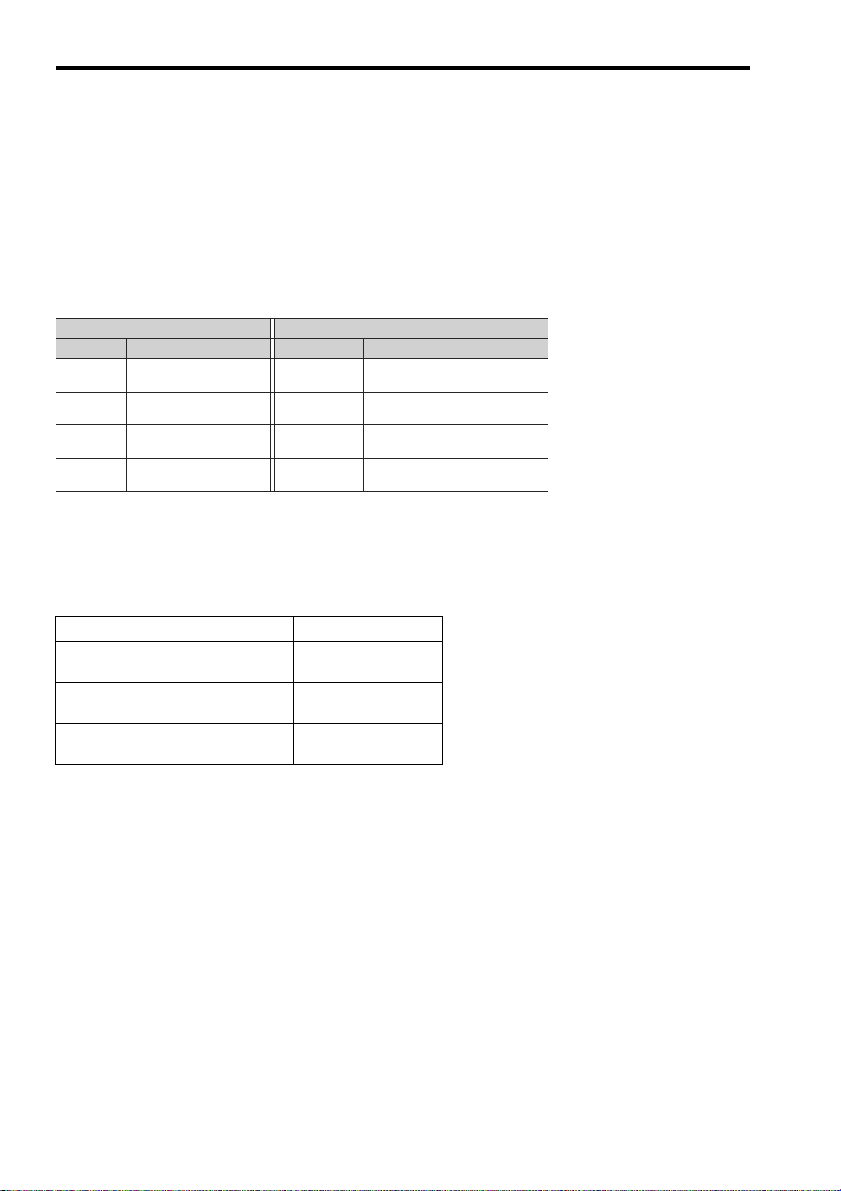
Notation for Parameters (Display Example for Pn170)
Digit Notation Setting Notation
Meaning Notation Meaning
Pn170.0
Pn170.1
Pn170.2
Pn170.3
Indicates the value for the
1st digit of parameter Pn170.
Indicates the value for the
2nd digit of parameter Pn170.
Indicates the value for the
3rd digit of parameter Pn170.
Indicates the value for the
4th digit of parameter Pn170.
Pn170.0 = x
or n.x
Pn170.1 = x
or n.x
Indicates that the value for the
1st digit of parameter Pn170 is x.
Indicates that the value for the
2nd digit of parameter Pn170 is x.
Pn170.2 = x
or n.x
Pn170.3 = x
or n.x
Indicates that the value for the
3rd digit of parameter Pn170 is x.
Indicates that the value for the
4th digit of parameter Pn170 is x.
Notation
Introduction
This instruction manual describes the JUNMA series AC SERVOPACKs. To properly use the JUNMA series AC
SERVOPACK, read these instructions thoroughly and retain for easy reference for inspections, maintenance, and so
on. Make sure that the end user receives this manual.
Notation Used in this Manual
Related Manuals
Refer to the following manuals as required.
Manual Name Manual Number
AC SERVO DRIVES
JUNMA SERIES
JUNMA series AC SERVOMOTOR
INSTRUCTIONS
Σ SERIES DIGITAL OPERATOR
SAFETY PRECAUTIONS
KAEPS80000023
TOBPC23026100
TOBPC73080000
E-4
Page 6
English
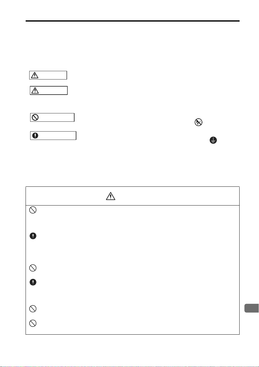
Safety Information
WARNING
CAUTION
PROHIBITED
MANDATORY
WARNING
The following conventions are used to indicate precautions in this manual. Failure to heed these precautions can
result in serious or possibly even fatal injury or damage to the products or to related equipment and systems.
Indicates precautions that, if not heeded, could possibly result in loss of life or serious injury.
Indicates precautions that, if not heeded, could result in relatively serious or minor
injury, damage to the product, or faulty operation.
In some situations, the precautions indicated could have serious consequences if not
heeded.
Indicates prohibited actions that must not be performed. For example, this symbol
would be used as follows to indicate that fire is prohibited: .
Indicates compulsory actions that must be performed. For example, this symbol
would be used as follows to indicate that grounding is compulsory: .
Notes for Safe Operation
Read these instructions thoroughly before checking products on delivery, storage and transportation, installation,
wiring, operation and inspection, and disposal of the AC SERVOPACK.
• Be sure to correctly connect the SERVOPACK connectors, CNA and CNB.
Incorrect wiring may result in electric shock, injury, or damage to the equipment. For the wiring
method, refer to 3.8 Wiring the Power Supply/Regenerative Unit Connector (CNA) and 3.9 Wiring
the Servomotor Main Circuit Cable Connector (CNB).
• Make sure that the emergency-stop circuit turns OFF the Servo ON signal and the power
supply of the main circuit when the EMG (emergency stop) signal turns ON.
Because of residual voltage, the servomotor rotates for a few seconds after the power supply has
turned OFF. This may result in injury or damage to the equipment. Make sure that the EMG means
the stop of the motor rotation.
• Never touch any rotating motor parts while the motor is running.
Failure to observe this warning may result in injury.
• Before starting operation with a machine connected, make sure that an emergency stop can
be applied at any time. Also, design the circuit's power supply to be automatically cut off if
/S-ON signal is OFF, and an emergency stop occurs at the same time.
Failure to observe this warning may result in injury.
• Never touch the inside of the SERVOPACKs.
Failure to observe this warning may result in electric shock.
• Do not touch terminals for five minutes after the power is turned OFF.
Residual voltage may cause electric shock.
E-5
Page 7
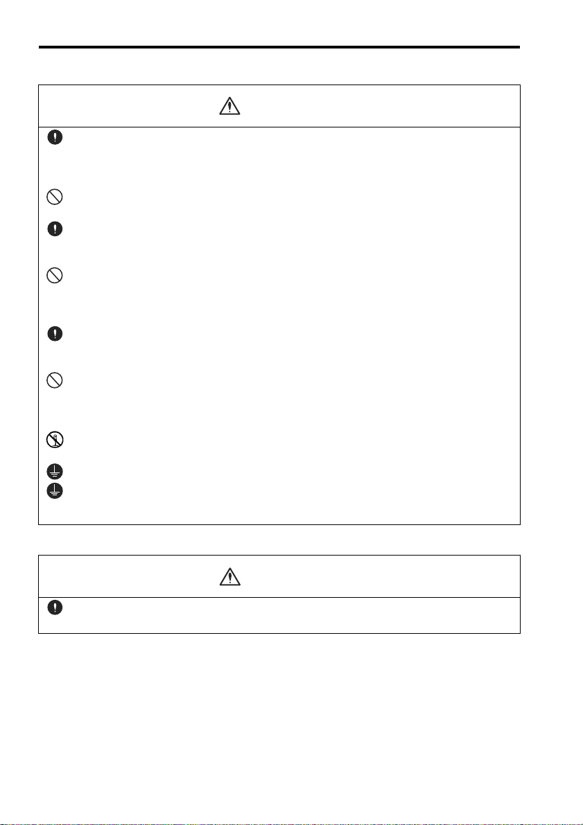
WARNING
CAUTION
• Follow the procedures and instructions for trial operation precisely as described in this manual.
Malfunctions that occur after the servomotor is connected to the equipment not only damage the
equipment, but may also cause an accident resulting in death or injury.
• Do not remove the cables, connectors, or optional items while the power is ON.
Failure to observe this warning may result in electric shock.
• Installation, wiring, advice on inspection and malfunction must be performed only by authorized personnel.
Failure to observe this warning may result in fire, electric shock, or injury.
• Do not damage, press, exert excessive force or place heavy objects on the cables or the
cables between other objects where they might be pinched.
Failure to observe this warning may result in electric shock, stopping operation of the product, or
burning.
• Provide an appropriate stopping device on the machine side to ensure safety.
A holding brake for a servomotor with brake is not a braking device for ensuring safety. Failure to
observe this warning may result in injury.
• Do not come close to the machine immediately after resetting momentary power loss to
avoid an unexpected restart.
Take appropriate measures to ensure safety against an unexpected restart. Failure to observe this
warning may result in injury.
• Do not modify the product.
Failure to observe this warning may result in injury or damage to the product.
• Be sure to correctly ground the SERVOPACK and the servomotor.
• Connect the SERVOPACK’s ground terminal to electrical codes (ground resistance: 100 Ω
or less).
Improper grounding may result in electric shock or fire.
Checking on Delivery
• Always use the servomotor and SERVOPACK in one of the specified combinations.
Failure to observe this caution may result in fire or malfunction.
E-6
Page 8
English
Storage and Transportation
CAUTION
CAUTION
• Do not store or install the product in the following places.
Failure to observe this caution may result in damage to the product.
• Locations subject to direct sunlight.
• Locations subject to temperatures outside the range specified in the storage or installation temperature conditions.
• Locations subject to humidity outside the range specified in the storage or installation humidity
conditions.
• Locations subject to condensation as the result of extreme changes in temperature.
• Locations subject to corrosive or flammable gases.
• Locations subject to dust, salts, or iron dust.
• Locations subject to exposure to water, oil, or chemicals.
• Locations subject to shock or vibration.
• Do not hold the product by the cables or motor shaft while transporting it.
Failure to observe this caution may result in injury or malfunction.
• Do not place any load exceeding the limit specified on the packing box.
Failure to observe this caution may result in injury or malfunction.
• If disinfectants or insecticides must be used to treat packing materials such as wooden
frames, pallets, or plywood, the packing materials must be treated before the product is
packaged, and methods other than fumigation must be used.
Example: Heat treatment, where materials are kiln-dried to a core temperature of 56°C for
30 minutes or more.
If the electronic products, which include stand-alone products and products installed in machines,
are packed with fumigated wooden materials, the electrical components may be greatly damaged by
the gases or fumes resulting from the fumigation process. In particular, disinfectants containing halogen, which includes chlorine, fluorine, bromine, or iodine can contribute to the erosion of the capacitors.
Installation
• Make sure to follow the conditions on 2.1 Installation Conditions.
Failure to observe this caution may result in electric shock, fire, or SERVOPACK’s malfunction.
• Do not step on or place a heavy object on the product.
Failure to observe this caution may result in injury.
• Do not cover the inlet or outlet parts and prevent any foreign objects, such as metallic fragment, or combustibles from entering the product.
Failure to observe this caution may cause internal elements to deteriorate resulting in malfunction or
fire.
• Be sure to install the product in the correct direction.
Failure to observe this caution may result in malfunction.
E-7
Page 9
CAUTION
CAUTION
• Provide the specified clearances between the SERVOPACK and the control panel or with
other devices.
Failure to observe this caution may result in fire or malfunction.
• SERVOPACK is precision equipment. Do not apply any strong impact.
Failure to observe this caution may result in malfunction.
Wiring
• Do not connect a three-phase power supply to the U, V, or W output terminals.
Failure to observe this caution may result in injury or fire.
• Securely connect the power supply terminals, regenerative unit connection terminal, and
motor main circuit cable terminals.
Failure to observe this caution may result in fire.
• Do not bundle or run power and signal lines together in the same duct. Keep power and signal lines separated by at least 30 cm (11.81 in).
Failure to observe this caution may result in malfunction.
• Use twisted-pair shielded wires or multi-core twisted pair shielded wires for I/O signal cable
and encoder cable.
The maximum length is 3 m (118.11 in) for reference input lines and is 20 m (787.40 in) for PG feedback lines.
• Do not touch the power terminals for five minutes after turning the power supply LED (PWR)
are OFF because high voltage may still remain in the SERVOPACK.
• Avoid frequently turning power ON and OFF. Do not turn power ON or OFF more than once
per minute.
Since the SERVOPACK has a capacitor in the power supply, a high charging current flows for 0.2
seconds when power is turned ON. Frequently turning power ON and OFF causes main power
devices such as capacitors and fuses to deteriorate, resulting in unexpected problems.
• Observe the following precautions when wiring connectors for power supply/regenerative
unit and for motor main circuit cable.
• Remove the connectors from the SERVOPACK prior to wiring.
• Insert only one wire per terminal on the connectors.
• Make sure that the core wire is not electrically shorted to adjacent core wires.
• Be sure to wire correctly and securely.
Failure to observe this caution may result in motor overrun, injury, or malfunction.
• Always use the specified power supply voltage.
Failure to observe this caution may result in damage to the SERVOPACK. For details on the power
supply voltage, refer to 8.1 Specifications.
E-8
Page 10
English
• Take appropriate measures to ensure that the input power supply is supplied within the
CAUTION
CAUTION
specified voltage fluctuation range. Be particularly careful in places where the power supply
is unstable.
An incorrect power supply may result in damage to the product.
• Install external breakers or other safety devices against short-circuiting in external wiring.
Failure to observe this caution may result in fire.
• Take appropriate and sufficient countermeasures for each when installing systems in the following locations.
Failure to observe this caution may result in damage to the product.
• Locations subject to static electricity or other forms of noise.
• Locations subject to strong electromagnetic fields and magnetic fields.
• Locations subject to possible exposure to radioactivity.
• Locations close to power supplies including power supply lines.
• Do not reverse the polarity of the battery when wiring with regenerative unit.
Failure to observe this caution may result in damage to the product.
Operation
• Conduct trial operation on the servomotor alone with the motor shaft disconnected from
machine to avoid any unexpected accidents.
Failure to observe this caution may result in injury.
• Before using a servomotor with a holding brake, run a trial operation to confirm that the holding brake activates correctly. Also, take appropriate measures to ensure safety against an
error such as signal line disconnection.
• Before starting any operation with a machine connected, change the settings of the SERVOPACK’s reference pulse with the PULSE rotary switch to match those of the machine.
Starting operation without matching the proper settings may cause the machine to run out of control
or malfunction.
• When using the servomotor for a vertical axis, install safety devices to prevent workpieces
from falling off because of alarms.
Workpiece’s falling off may result in injury or malfunction.
• Do not touch the SERVOPACK heatsinks, regenerative unit, or servomotor while power is
ON or soon after the power is turned OFF.
Failure to observe this caution may result in burns due to high temperatures.
• When an alarm occurs, remove the cause, turn OFF the power and ON again after confirming safety, and then resume operation.
Failure to observe this caution may result in injury.
• Do not use the holding brake of the servomotor for ordinary braking.
Failure to observe this caution may result in malfunction.
E-9
Page 11
CAUTION
CAUTION
Maintenance and Inspection
• Do not open the SERVOPACK case for 5 minutes after the power supply lamp (PWR LED)
goes out. High voltage may remain in the SERVOPACK after the power supply has been
turned OFF.
• After turning OFF the power supply, wait 15 minutes before replacing the cooling fan.
Failure to observe this caution may result in burns because the cooling fan is hot.
• Mount the cooling fan in the correct way explained in 6.3 Replacement of Cooling Fan.
Mounting the cooling fan in the incorrect direction may result in the breakdown of the SERVOPA CK .
• Do not attempt to change wiring while the power is ON.
Failure to observe this caution may result in electric shock or injury.
Disposal
• When disposing of the products, treat them as general industrial waste.
General Precautions
Note the following to ensure safe application.
• The drawings presented in this manual are sometimes shown without covers or protective guards. Always
replace the cover or protective guard as specified first, and then operate the products in accordance with the
manual.
• The drawings presented in this manual are typical examples and may not match the product you received.
• This manual is subject to change due to product improvement, specification modification, and manual
improvement. When this manual is revised, the manual code is updated and the new manual is published as
a next edition.
• If the manual must be ordered due to loss or damage, inform your nearest Yaskawa representative or one of
the offices listed on the back of this manual.
• Yaskawa will not take responsibility for the results of unauthorized modifications of this product. Yaskawa
shall not be liable for any damages or troubles resulting from unauthorized modification.
E-10
Page 12
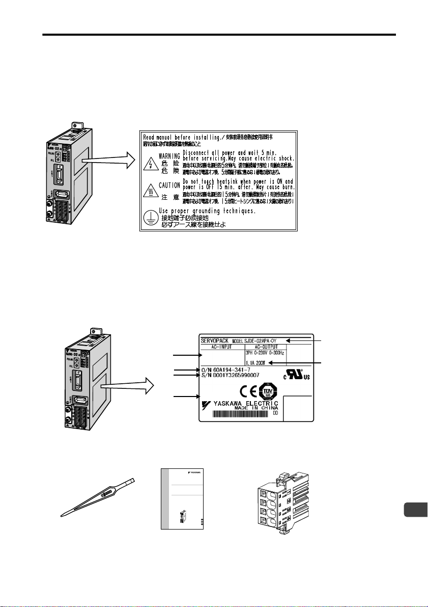
1.1 Warning Label
English
SERVOPACK's Warning Label
R
E
F
C
0
8
9
A
B
D
E
F
4
5
3
2
6
7
1
C
0
8
9
A
B
D
E
F
4
5
3
2
6
7
1
SERVOPACK
model
Serial number
SERVOPACK
version
Applicable
power supply
Applicable motor
capacity
Order number
SJDE
SERVOPACK
R
E
F
C
0
8
9
A
B
D
E
F
4
5
3
2
6
7
1
C
0
8
9
A
B
D
E
F
4
5
3
2
6
7
1
One screwdriver for
selecting the pulse
and setting the filter
One copy of this
Instruction Manual
Connector for power supply/
regenerative unit
(model: JZSP-CHG9-1)
Nameplate
1PH 200-230V 50/60Hz
1PH 100-115V 50/60Hz
2.5A
03404
1 Before Use
1.1 Warning Label
A warning label is located on the side of the SERVOPACK.
1.2 Checking Products
Confirm that the following items have been delivered together with the SERVOPACK. Verify that the ordered product as received by the model number marked on the nameplate on the SERVOPACK.
If you find any irregularities such as incorrect SERVOPACK model, damages, and missing parts or items, contact
your Yaskawa representative or the dealer from whom you purchased the products.
AC SERVOPACK
JUNMA Series
INSTRUCTIONS
Model:SJDE-APA-OY
To properly use the product, read this manual thoroughly and retain for
easy reference, inspection, and maintenance. Ensure the end user
receives this manual.
ACԎ᳡ܗ
JUNMA㋏߫
Փ⫼䇈ᯢк
ൟো˖SJDE-APA-OY
ЎњᅝܼՓ⫼ᴀѻકˈ䇋ࡵᖙ䯙䇏䆹Փ⫼䇈ᯢкDŽ
ˈ䇋ཹֱㅵ䆹Փ⫼䇈ᯢкˈᑊᇚ݊Ѹ㟇᳔㒜⫼᠋ЁDŽ
ACサーボパック
JUNMAシリーズ
取扱説明書
形式:SJDE-APA-OY
製品を安全にお使い頂くために,本書を必ずお読みください。
また,本書をお手元に保管していただくとともに,最終的に本製品をご使用になる
ユーザー様のお手元に確実に届けられるよう,お取り計らい願います。
R
E
F
English
∝䇁
日本語
MANUAL NO. TOMP C710806 06A
E-11
Page 13
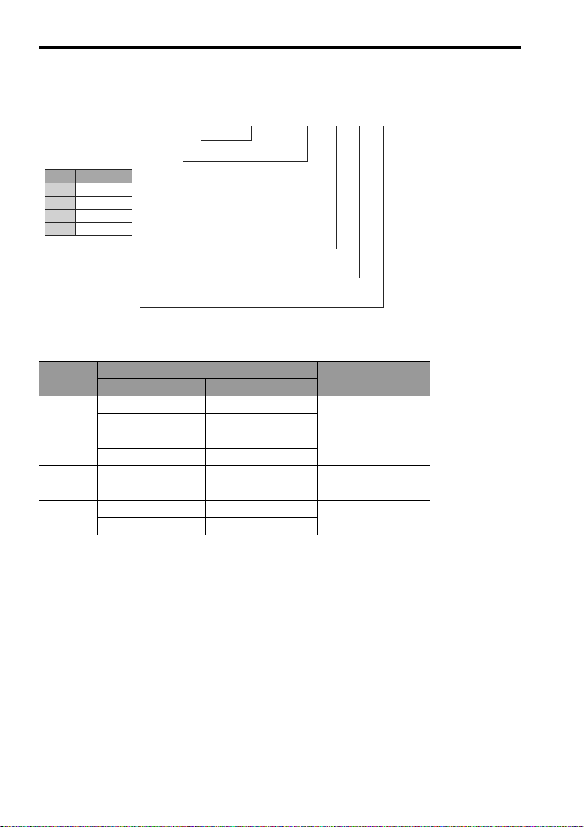
1.3 Model Designation
SJDE㧙02 A P A㧙OY
JUNMA series SERVOPACK SJDE
Applicable servomotor capacity
Power supply voltage
Interface specification
Code
A: 200 VAC
Design revision order
A
P: Pulse train reference
01
02
04
08
Output (W)
100
200
400
750
1.3 Model Designation
1.4 SERVOPACKs and Applicable Servomotors
Rated
Output
100W
200W
400W
750W
Without Brakes With Brakes
SJME-01AM41 SJME-01AM4C
SJME-01AM41-OY SJME-01AM4C-OY
SJME-02AM41 SJME-02AM4C
SJME-02AM41-OY SJME-02AM4C-OY
SJME-04AM41 SJME-04AM4C
SJME-04AM41-OY SJME-04AM4C-OY
SJME-08AM41 SJME-08AM4C
SJME-08AM41-OY SJME-08AM4C-OY
Servomotor
SERVOPACK
SJDE-01APA-OY
SJDE-02APA-OY
SJDE-04APA-OY
SJDE-08APA-OY
E-12
Page 14
English
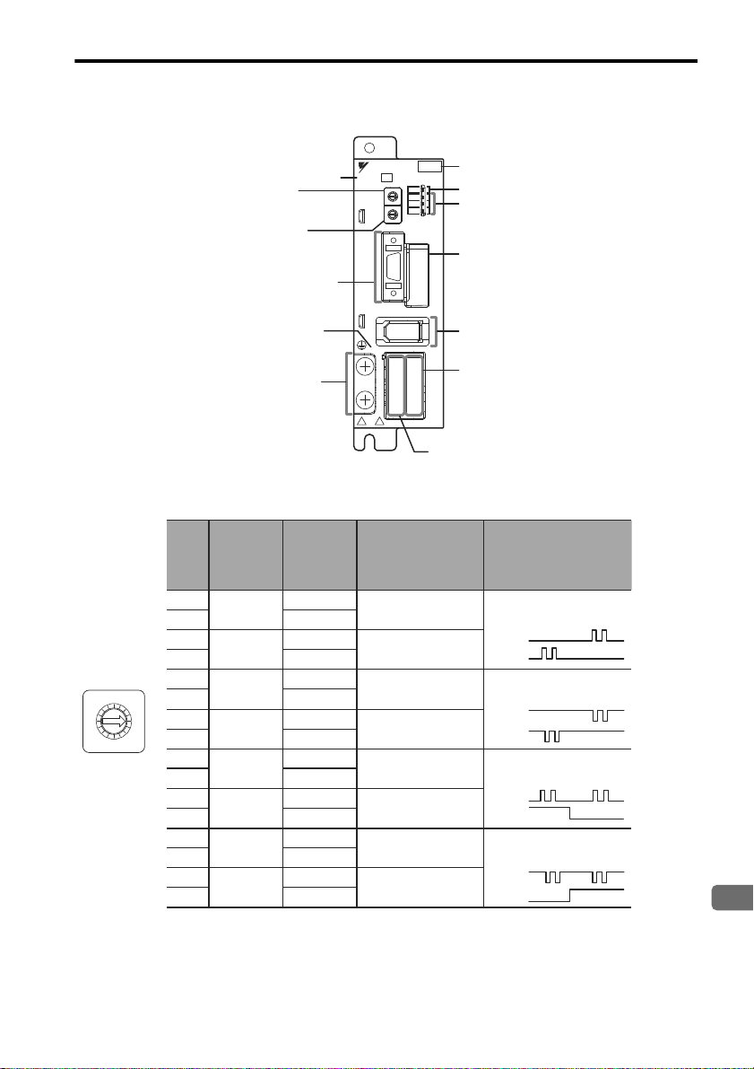
1.5 Part Names and Functions
Type
Rotary switch for reference
filter setting (FIL)
Rotary switch for reference
pulse setting (PULSE)
Power supply indicator
(PWR)
Connector for power supply /
regenerative unit (CNA)
Connector for motor main
circuit cable (CNB)
Encoder connector (CN2)
Ground terminal
I/O signal connector (CN1)
Alarm indicators (AL1 to AL3)
Reference indicator (REF)
Input voltage
200V
YASKAWA
SJDE- 04 APA-OY
FIL
PULSE
REF
AL1
AL2
AL3
C
N
2
PWR
L1
L2
+
CNA CNB
U
V
W
-
Connector for
communication unit (CN52)
C
N
1
9
F
A
E
B
D
C
4
5
6
7
0
1
8
2
3
9
F
A
E
B
D
C
4
5
6
7
0
1
8
2
3
PULSE
C
0
8
9
A
B
D
E
F
4
5
3
2
6
7
1
Set
Value
Reference Pulse
Connection Method
Reference
Pulse Type
Input
Frequency
Open collector
or line driver
Line driver
Open collector
or line driver
Line driver
Open collector
or line driver
Line driver
Open collector
or line driver
Line driver
CW + CCW
Positive logic
CW + CCW
Negative logic
Mark + pulse sequence,
Positive logic
Mark + pulse sequence,
Negative logic
0
1
2
3
4
5
6
7
8
9
A
B
C
D
E
F
to 187.5 kpps
187.5 to
750 kpps
to 187.5 kpps
187.5 to
750 kpps
to 187.5 kpps
187.5 to
750 kpps
to 187.5 kpps
187.5 to
750 kpps
Reference
Pulse
Resolution
(P/REV)
1000
2500
5000
10000
1000
2500
5000
10000
1000
2500
5000
10000
1000
2500
5000
10000
PULS
SIGN
CW
CCW
CW
CCW
PULS
SIGN
Reference Pulse Setting (PULSE)
1.5 Part Names and Functions
Note: 1. Make settings after turning OFF the power.
2. The factory setting is 0.
E-13
Page 15
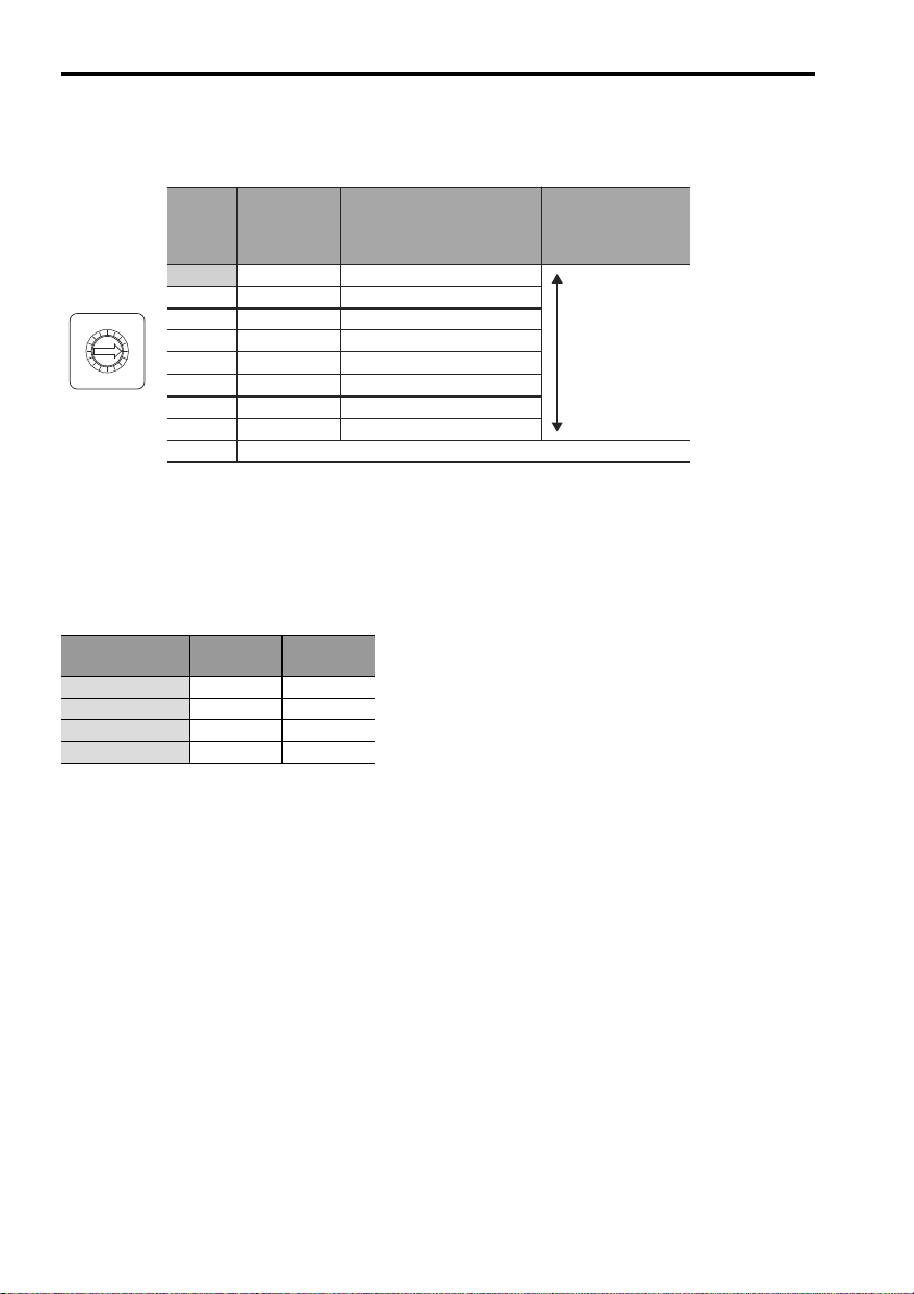
1.5 Part Names and Functions
Description
Approx. Time between
Completing Reference and
Completing Positioning
(Settling Time)*
3
Acceleration/
Deceleration
Time for Step
Reference
*4
Filter
Setting
Value*
2
Do not set 8 through F.
Small filter time
constant (short
positioning time)
Large filter time
constant
(little vibration
with a long
positioning time)
0*
1
1
2
3
4
5
6
7
8 to F
45 ms
50 ms
60 ms
65 ms
70 ms
80 ms
85 ms
170 ms
100 to 200 ms
110 to 220 ms
130 to 260 ms
150 to 300 ms
170 to 340 ms
200 to 400 ms
250 to 500 ms
500 to 1000 ms
FIL
C
0
8
9
A
B
D
E
F
4
5
3
2
6
7
1
Reference Filter Setting Rotary Switch (FIL)
When the digital operator or JunmaWin is used, set Pn170.0 to 0 to enable the setting of FIL switch.
* 1. The factory setting is 0. If the machine vibrates, this value must be changed.
* 2. If the machine vibrates when starting or stopping the machine, set a larger value.
* 3. The value depends on conditions such as the level of command acceleration and deceleration, the machine rigidity
and the motor resolution (PULSE switch).
* 4. Select the correct servomotor capacity with these values if using a step reference that has no acceleration or decel-
eration time.
Reference Display (REF)
Indicators*
Lit orange. OFF −
Blinks orange. OFF Input
Lit green. ON −
Blinks green. ON Input
* Lit yellow for 1s when the clear signal is input.
Motor
Power
Reference
Pulses
E-14
Page 16
1.5 Part Names and Functions
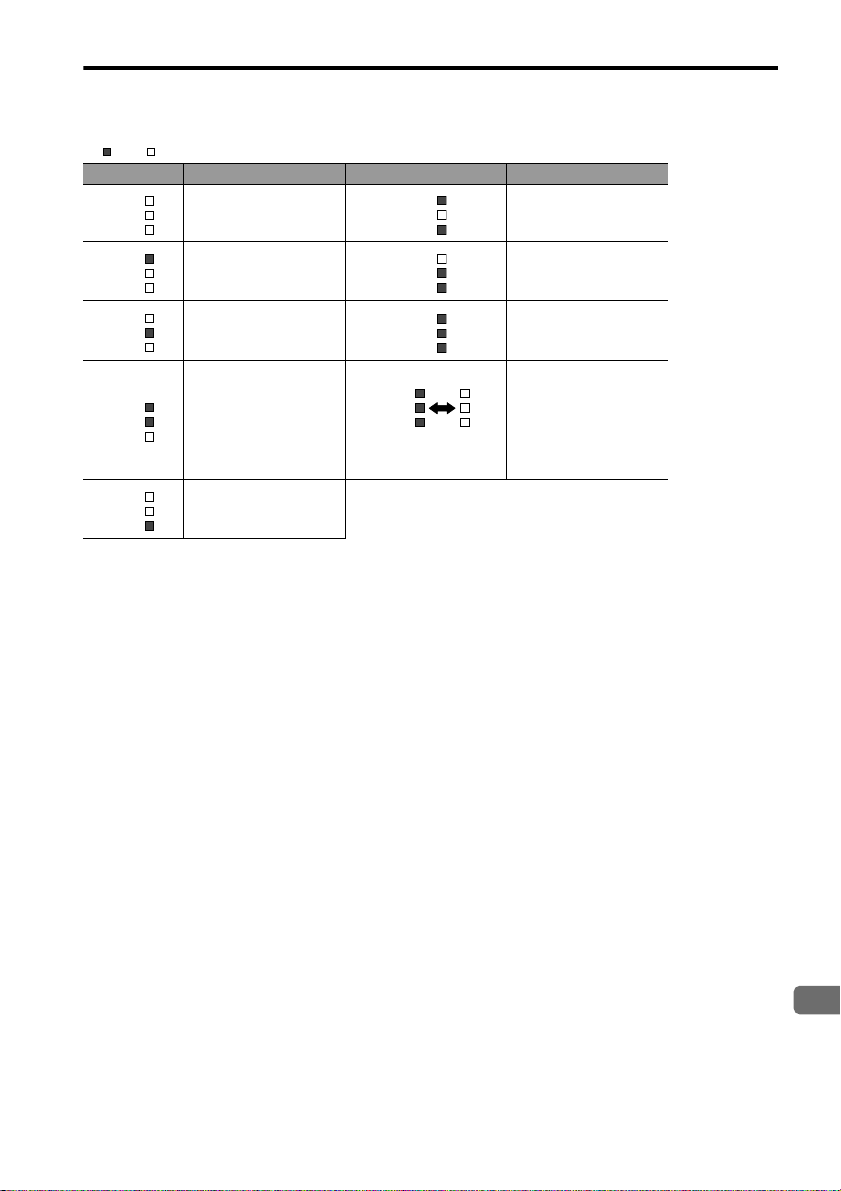
English
: Lit : OFF
AL1
AL2
AL3
AL1
AL2
AL3
AL1
AL2
AL3
AL1
AL2
AL3
AL1
AL2
AL3
AL1
AL2
AL3
AL1
AL2
AL3
Blinks at regular
intervals.
AL1
AL2
AL3
AL1
AL2
AL3
Alarm Display (AL1, AL2, and AL3)
Indicators Meaning of Alarm Indicators Meaning of Alarm
Normal Overcurrent
Speed error
Overload System error
Encoder error
Voltage error
SERVOPACK’s built-in
fan stop
Rotary switch for
reference pulse setting
(PULSE) changed.
The settings were
changed for parameters that require the
power to be restarted.
E-15
Page 17

2.1 Installation Conditions
2 Installation
The following shows the installation location and method of the SERVOPACK.
2.1 Installation Conditions
Item Specifications
Operating temperature 0 °C to +55 °C
Operating humidity 90% RH or less (with no condensation)
Storage temperature -20 °C to +70 °C
Storage humidity 90% RH or less (with no condensation)
Installation site Free of corrosive gases
Altitude 1000 m or below
Vibration resistance
Shock resistance
Operating conditions Installation category (overvoltage category): II
Installation in a control
panel
Installation near a
Installation
Site
heating unit
Installation near a
source of vibration
Installation at a site
exposed to corrosive
gas
Free of dust and iron powder
Clean and dry
2
4.9 m/s
2
19.6 m/s
Pollution degree: 2
Protection class: IP10 (EN50178)
Design the control panel size, unit layout, and cooling method so
the temperature around the SERVOPACK does not exceed 55 °C.
Note: For long-term reliability the internal temperature of the control
panel must be 45 °C or lower.
Minimize the heat radiating from the heating unit as well as any
temperature rise caused by natural convection so the temperature
around the SERVOPACK does not exceed 55 °C.
Install a vibration isolator beneath the SERVOPACK to avoid subjecting
it to vibration.
Corrosive gas does not have an immediate effect on the SERVOPACK
but will eventually cause the electronic components and contactor-
related devices to malfunction. Take appropriate action to avoid corrosive gas.
E-16
Page 18
2.2 Installation Method
English
SERVOPACK installation plate
M4 screw
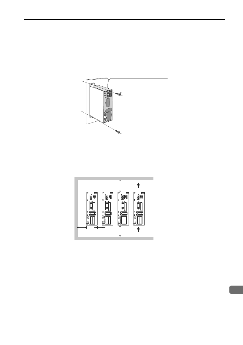
2.2 Installation Method
Installation Method and Direction
• Install the SERVOPACK perpendicular to the wall. The SERVOPACK contains a built-in fan for cooling and
must be mounted in the specified direction.
• Connect the mounting holes securely to the mounting surface with M4 screws (two mounting holes).
Space between SERVOPACK Units
• Be sure to keep a space between adjacent SERVOPACK units if they are mounted inside the control panel so that
the units can be cooled.
• Do not cover the inlet or outlet parts and prevent any foreign objects, such as metallic fragment, or combustibles
from entering the product.
Failure to observe this caution may cause internal elements to deteriorate resulting in malfunction or fire.
30 mm
min.
YASKAWA
SJDE- 04 APA-OY
A
9
8
7
PULSE
A
9
8
7
FIL
C
N
1
C
N
2
PWR
L1
L2
+
-
50 mm
min.
YASKAWA
YASKAWA
200V
200V
SJDE- 04 APA-OY
D
C
B
E
A
F
CTL
9
0
8
1
7
2
6
3
5
4
AL1
PULSE
D
C
AL2
B
E
A
F
9
0
8
1
AL3
7
2
6
3
5
4
FIL
C
N
1
C
N
2
PWR
U
L1
V
L2
+
W
-
CNA CNB
10 mm
min.
SJDE- 04 APA-OY
D
C
B
E
A
F
9
0
8
1
7
2
6
3
5
4
PULSE
D
C
B
E
A
F
9
0
8
1
7
2
6
3
5
4
FIL
C
N
1
C
N
2
PWR
L1
L2
+
-
CNA CNB
50 mm
min.
D
C
B
E
F
CTL
0
1
2
6
3
5
4
AL1
D
C
AL2
B
E
F
0
1
AL3
2
6
3
5
4
U
V
W
CNA CNB
YASKAWA
200V
SJDE- 04 APA-OY
CTL
AL1
PULSE
AL2
AL3
FIL
C
N
1
C
N
2
PWR
U
V
W
Air outlet direction
200V
D
C
B
E
A
F
CTL
9
0
8
1
7
2
6
3
5
4
AL1
D
C
AL2
B
E
A
F
9
0
8
1
AL3
7
2
6
3
5
4
U
L1
V
L2
+
W
-
CNA CNB
Air inlet direction
E-17
Page 19
3.1 Precautions on Wiring
WARNING
200V
YASKAWA
SJDE- 04 APA-OY
CTL
AL1
AL2
AL3
9
F
A
E
B
D
C
4
5
6
7
8
0
1
2
3
9
F
A
E
B
D
C
4
5
6
7
8
0
1
2
3
C
N
1
C
N
2
PWR
L1
L2
+
CNA CNB
U
V
W
-
200V
YASKAWA
SJDE- 04 APA-OY
FIL
PULSE
FIL
PULSE
FIL
PULSE
CTL
AL1
AL2
AL3
9
F
A
E
B
D
C
4
5
6
7
8
0
1
2
3
9
F
A
E
B
D
C
4
5
6
7
8
0
1
2
3
C
N
1
C
N
2
PWR
L1
L2
+
CNA CNB
U
V
W
-
200V
YASKAWA
SJDE- 04 APA-OY
CTL
AL1
AL2
AL3
9
F
A
E
B
D
C
4
5
6
7
8
0
1
2
3
9
F
A
E
B
D
C
4
5
6
7
8
0
1
2
3
C
N
1
C
N
2
PWR
L1
L2
+
CNA CNB
U
V
W
-
3 Wiring
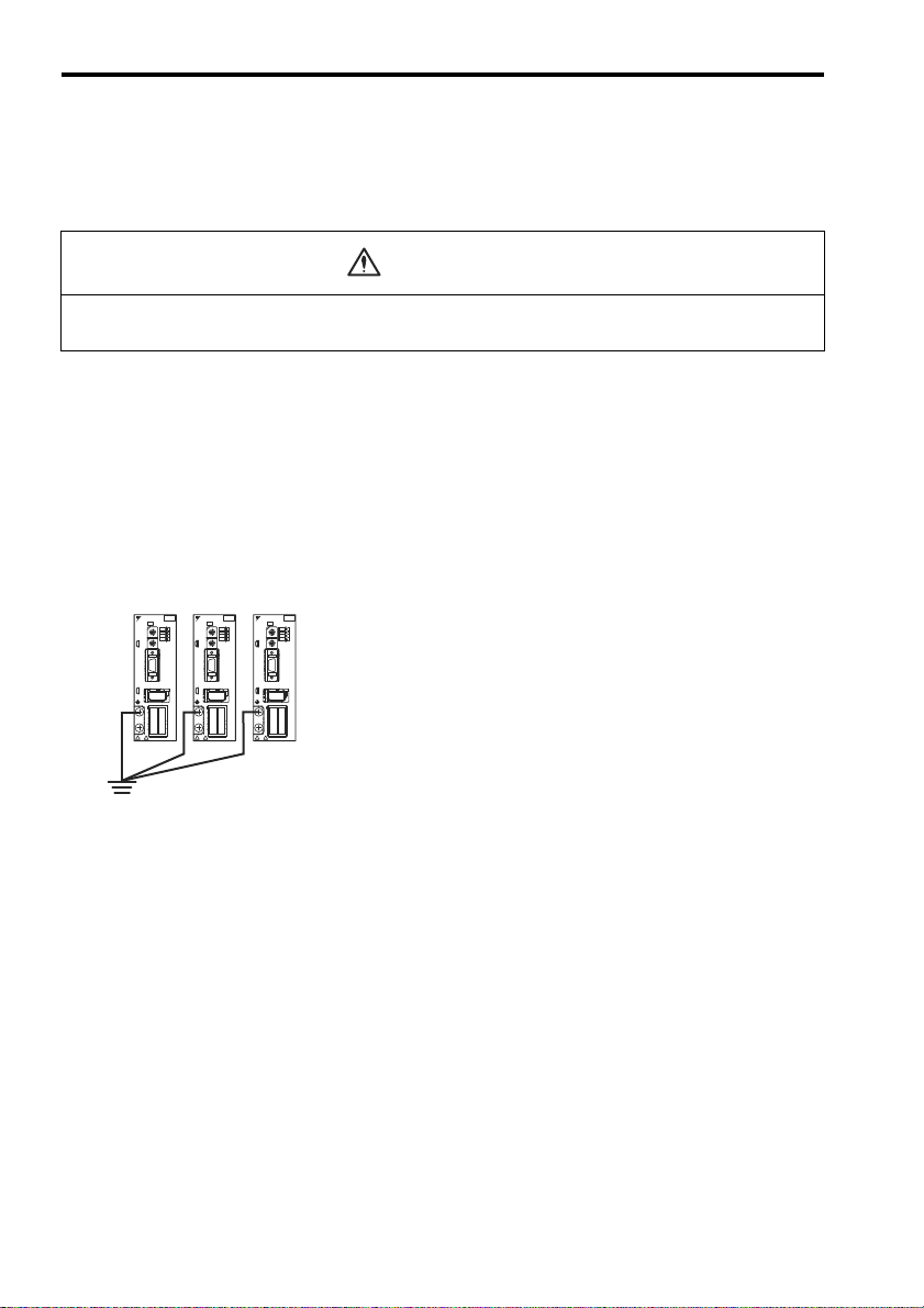
3.1 Precautions on Wiring
• Be sure to correctly ground the SERVOPACK and the servomotor.
• Wiring must be performed by an authorized person qualified in electrical work.
Protection for Power Supply Line
• Use a molded-case circuit breaker and fuse to protect the power supply line from high voltage. The SJDE SERVOPACK connects directly to a commercial power supply without a transformer, so always use a circuit breaker
and fuse to protect the SERVOPACK from accidental high voltage.
Caution for Grounding
Consider the following conditions when grounding the SERVOPACK.
• For a ground wire, use as thick a cable as possible (2.0 mm2 or thicker).
• A ground resistance of 100 (Ω) or less is recommended.
• Ground to one point only.
Caution for Cable
• For wiring, use the specified cables. Use cables that are as short as possible.
• Do not bend or apply tension to cables. The conductor of a signal cable is very thin (0.08 to 0.12 mm2), so handle
the cables carefully.
E-18
Page 20
3.1 Precautions on Wiring
English
Other Precautions
• Make sure that the emergency-stop circuit turns OFF the /S-ON signal as well as the power supply of the main
circuit. Refer to 3.14 EMG Sequence.
• An overtravel function is not provided for the SERVOPACK.
For system safety, include a sequence so that the /S-ON signal will turn OFF when the limit switch is activated.
• If the servomotor is used to drive a vertical axis, install a safety device with an alarm function to prevent the
workpiece from falling down. Failure to observe this precaution may result in injury or damage to the equipment
from fallen workpieces.
• Install an interlock system in the circuit to avoid any accident when opening or closing the machine’s protective
cover.
• Whether the electricity is served or not to the motor, do not use the motor being rotated from the outside.
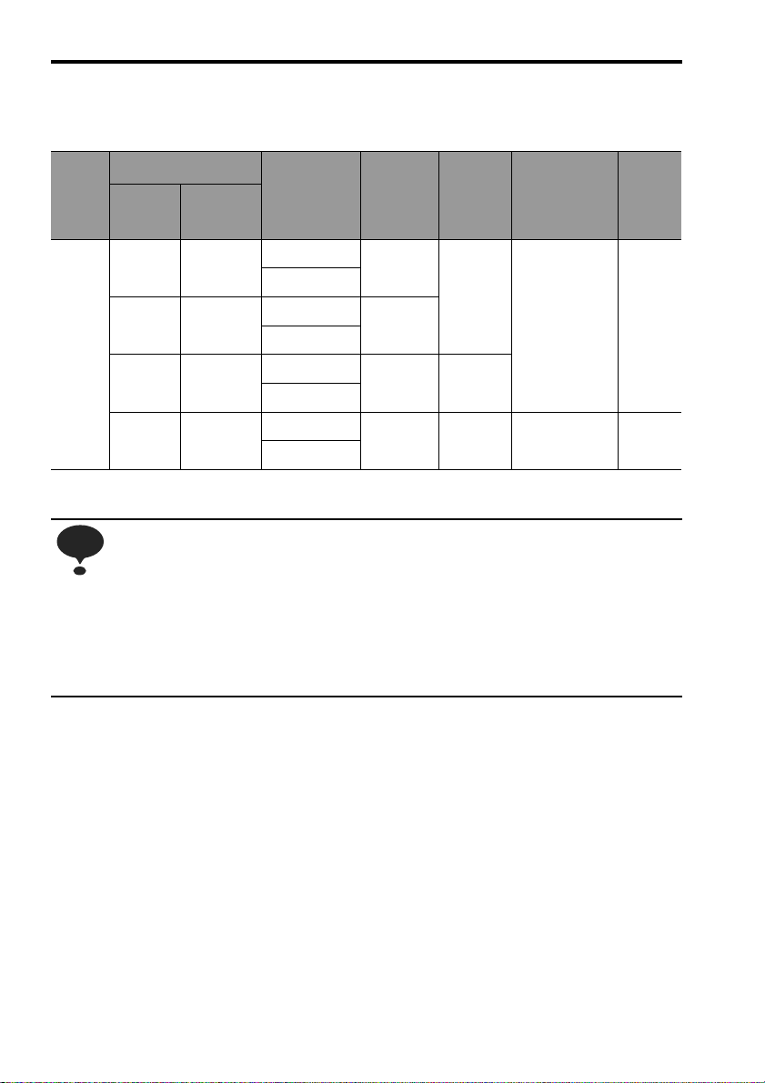
• When restarting the power supply soon after turning OFF, alarm may occur to the SERVOPACK. Refer to the
power supply holding time in the following table to restart the power supply correctly.
SERVOPACK Min. Waiting Time
Model Capacity
SJDE-01APA-OY
SJDE-04APA-OY
SJDE-08APA-OY
100W
200W
400W
750W
before Restarting
(s)
20SJDE-02APA-OY
30
Power Loss
Power Loss with SERVOPACK Rated Output
Main
Circuit
Power
Supply
Max. Applica-
ble Servomotor
Capacity
kW
0.1 SJDE-01APA-OY 0.84 6 0.9 4.2
SERVOPACK
Model No.
Output
Current
(Effective
Value)
A
Main
Circuit
Power
Loss
W
Diode
Power
Loss
W
IPM
Power
Loss
W
Control
Circuit
Power
Loss
W
To ta l
Power
Loss
W
15
Single-
phase
200 V
Note: Valued obtained with the servomotor with the rated output.
0.2 SJDE-02APA-OY 1.1 8 1.8 5.8 17
0.4 SJDE-04APA-OY 2.0 16 3.6 11.9 25
0.75 SJDE-08APA-OY 3.7 27 6.4 20.3 36
E-19
9
Page 21
3.1 Precautions on Wiring
NOTE
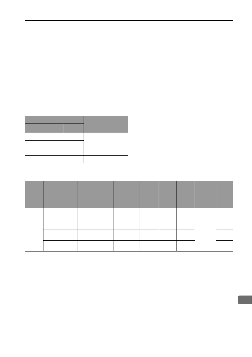
Molded-Case Circuit Breaker (MCCB) or Fuse Capacity Relation to Power-Supply Capacity
MCCB or Fuse Capacity Relation to Power-Supply Capacity
∗1
4
External Fuse
Model No.
[Power-Supply
Capacity
∗2
Arms]
0KLK 015.T
[15]
0KLK 030.T
[30]
Inrush
Current
Main
Circuit
Power
Supply
Single-
phase
200 V
* 1. Valued obtained with the servomotor with the rated output.
* 2. Fuse manufactured by Littelfuse Inc.
SERVOPACK
CapacitykWModel No.:
SJDE-
0.1 01APA-OY
0.2 02APA-OY
0.4 04APA-OY
0.75 08APA-OY
Ground Fault
The ground protection circuit is designed for ground fault inside the motor windings while the motor
is running. Therefore, it may not protect the system under the following conditions.
• A low-resistance ground fault occurs between the main circuit cable and connector for the servomotor.
• The power supply is turned ON during a ground fault.
To configure a safer system, install an earth leakage breaker for protection against overloads and
short-circuiting, or install an earth leakage breaker combined with a wiring circuit breaker for ground
protection.
Applicable Ser-
vomotor
Model:
SJME-
01AM41
01AM41-OY
02AM41
02AM41-OY
04AM41
04AM41-OY
08AM41
08AM41-OY
PowerSupply
Capacity
kVA
0.4
0.75
1.2 8
2.2 16
MCCB
Current
Capacity
Arms
A
30
60
E-20
Page 22
English
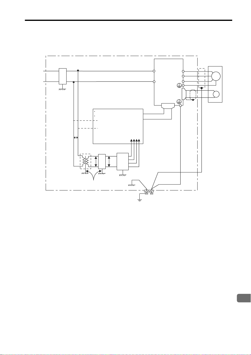
Noise Prevention
Example of Wiring for Noise Prevention
3.1 Precautions on Wiring
100 VAC
200 VAC
Noise filter
*1
Min. wire size
2
: 3.5 mm
*2
2LF
Casing
P
Min. wire size: 3.5 mm
Operation relay sequence
User signal generating circuit
*3
1LF
P
Casing
Casing
P
2
*2
AVR
(Ground
-ing)
2 mm2 or larger
Min. wire size: 3.5 mm
Casing
Casing
SERVOPACK
SJDE
L1
L2
Grounding plate
Groudning: Ground to one point only.
Min. grounding resistance: 100 Ω
CN1
2
*2
U
V
W
CN2
Min. wire size
: 3.5 mm
Min. wire size
: 3.5 mm
Servomotor
2
2
* 1. A 100 VAC power supply can be used with a SERVOPACK version 03404 or firmware version 0004 or later.
2
* 2. For the wires connected to the casings for installation purposes, use wires with a diameter of 3.5 mm
or larger.
Flat braided copper wires are recommended.
* 3. Use twisted pair wires for section P.
M
(FG)
PG
Correct Grounding
• Servomotor frame grounding:
Be sure to connect the FG grounding terminal on the frame of the servomotor to the grounding terminal on the
SERVOPACK.
• Be sure to ground the grounding terminal of the SERVOPACK.
• If the wires of the servomotor’s main circuit are laid in a metal conduit, ground the conduit and the grounding
box.
One-point grounding must be used.
E-21
Page 23
3.1 Precautions on Wiring
Noise Filters
Use noise filters to prevent any noise interference from the power-supply line.
The following table lists the recommended noise filters.
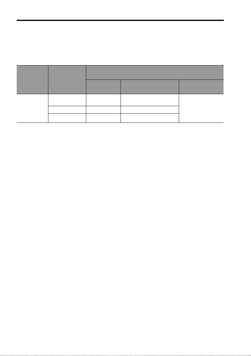
Recommended Noise Filters
Power-Supply
Volt age
Single-
phase
200 V
SERVOPACK
Model
SJDE-01APA-OY
to 02APA-OY
SJDE-04APA-OY
SJDE-08APA-OY
Recommended Noise Filters
Model Specifications Manufacturer
FN2070-6/07 Single-phase 250 VAC, 6A
FN2070-10/07 Single-phase 250 VAC,10A
FN2070L-16/07 Single-phase 250 VAC, 16A
Schaffner EMC, Inc.
E-22
Page 24
English
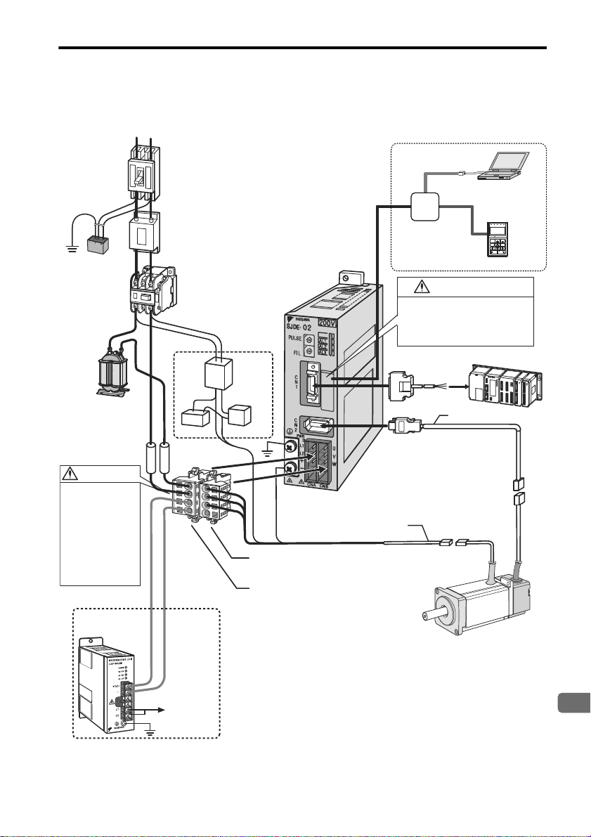
3.2 System Configuration
Connectors for motor
main circuit cable (CNB
)
Connectors for power
supply/regenerative unit
(
CNA
)
To the control
circuits of
magnetic
contactor
Encoder cable (for relay
)
Motor main circuit cable
(
for relay)
I/O signal cable
Host controller
SJDE
SERVOPACK
SJME
Servomotors
L1 L2
R
E
F
Brake relay
24-VDC
power
supply
*
3
Used for a
servomotor
with a brake.
Used for a
regenerative unit.
C
0
8
9
A
B
D
E
F
4
5
3
2
6
7
1
C
0
8
9
A
B
D
E
F
4
5
3
2
6
7
1
Noise filter
Used to eliminate suppress noise
from power lines for CE marking
requirements.
Molded-case circuit breaker
To protect the equipment and wiring,
always connect a molded-case circuit
breaker.
Magnetic contactor
Used to turn OFF the servo
power supply when using a
regenerative unit or in case
of emergency.
Power supply
Single-phase 100 VAC
*
1
Single-phase 200 VAC
Regenerative unit
Used if regenerative
energy is high.
AC reactor
Used for a power
supply harmonic
suppression.
Fuse
To protect the
equipment, always
install fuses.
Surge absorber
(for lightning
surge)
When not using a digital operator or
JunmaWin, never open the protective
cover for the connector.
If the connector is used, a
SERVOPACK failure may result.
CAUTION
Correctly connect the
connectors CNA and CNB.
Incorrect wiring may
result in electric shock,
injury, or damage to
the equipment.
After wiring, install the
connectors as explained
in 3.8 Wiring the Power
Supply/Regenerative
Unit Connector (CNA)
and 3.9 Wiring the
Servomotor Main Circuit
Cable Connector (CNB).
WARNING
Varistor
APA-OY
Communication unit
VCMP
SVON COIN TGON REF
CHARGE
ALARM
DATA
JOG
SVON
SCROLL
MODE/SET
RESET
SERVO
READ WRITE
SERVO
YASKAWA
DIGITAL OPERATOR JUSP-OP05A-1-E
PC running
JunmaWin
Digital operator
When using a digital operator, or JunmaWin*
2
3.2 System Configuration
* 1. A 100 VAC power supply can be used with a SERVOPACK version 03404 or firmware version 0004 or later.
* 2. A digital operator or JunmaWin can be used with a SERVOPACK version 03303 or firmware version 0003 or later.
* 3. Prepare a 24-VDC power supply for the brake separately from the sequence power supply.
E-23
Page 25
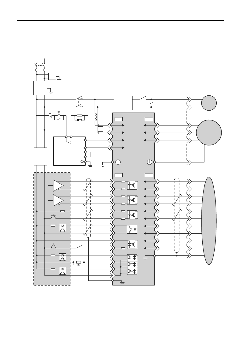
3.3 Standard Connection
Power supply
Single-phase 200 V to 230 VAC, Single-phase 100 V to 115 VAC
*
1
50/60Hz
AVR 1
*
2
24 V power supply
Brake
V
W
FG
U
V
W
U
V
W
U
/Z
B
+
A
+
PG0V
PG5VCW,PULS
/CW,/PULS
CCW,SIGN
/CCW,/SIGN
CLR
/CLR
PCO
SG-PCO
+24VIN
/S-ON
ALM
/BK
/COIN
SG-COM
2
3
4
1
2
3
4
5
6
7
8
9
10
12
1
2
3
4
1
2
3
4
8
9
5
6
7
Shell
Shell
Shield
Shield
Flywheel diode
10
11
12
13
14
1L1
L2
+
2
3
1
2
3
4
5
6
7
8
9
10
1
6
5
Varistor
200 V to
230 VAC,
100 V to
150 VAC
*
1
+
24V
0V
Molded-case circuit breaker
SERVOPACK
Controller
Regenerative unit
JUSP-
RG08E-E
Servomotor
Encoder
Surge absorber (for lightning surge)
Surge
absorber
*
3
L1
SW1
MC1
MC1
Ry1
Ry1
C1 C2
+
Y4
Y5
SW2
MC1
L2
75Ω
75Ω
75Ω
75Ω
75Ω
75Ω
2.2kΩ
CNA CNB
CN1 CN2
3.4kΩ
+
24V
0V
Noise
filter
Reactor
AVR 2
24 V power
supply
200 V to
230 VAC
100 V to
115 VAC
*
1
–
–
* Prepare a 24-VDC power supply
for the brake separate from the
sequence power supply.
Fuse
Fuse
MC1
A–
B–
3.3 Standard Connection
* 1. A 100 VAC power supply can be used with a SERVOPACK version 03404 or firmware version 0004 or later.
* 2. Prepare a 24 VDC power supply for sequence separately from the 24 VDC power supply for brake.
* 3. For switching surge
E-24
Page 26
3.3 Standard Connection
English
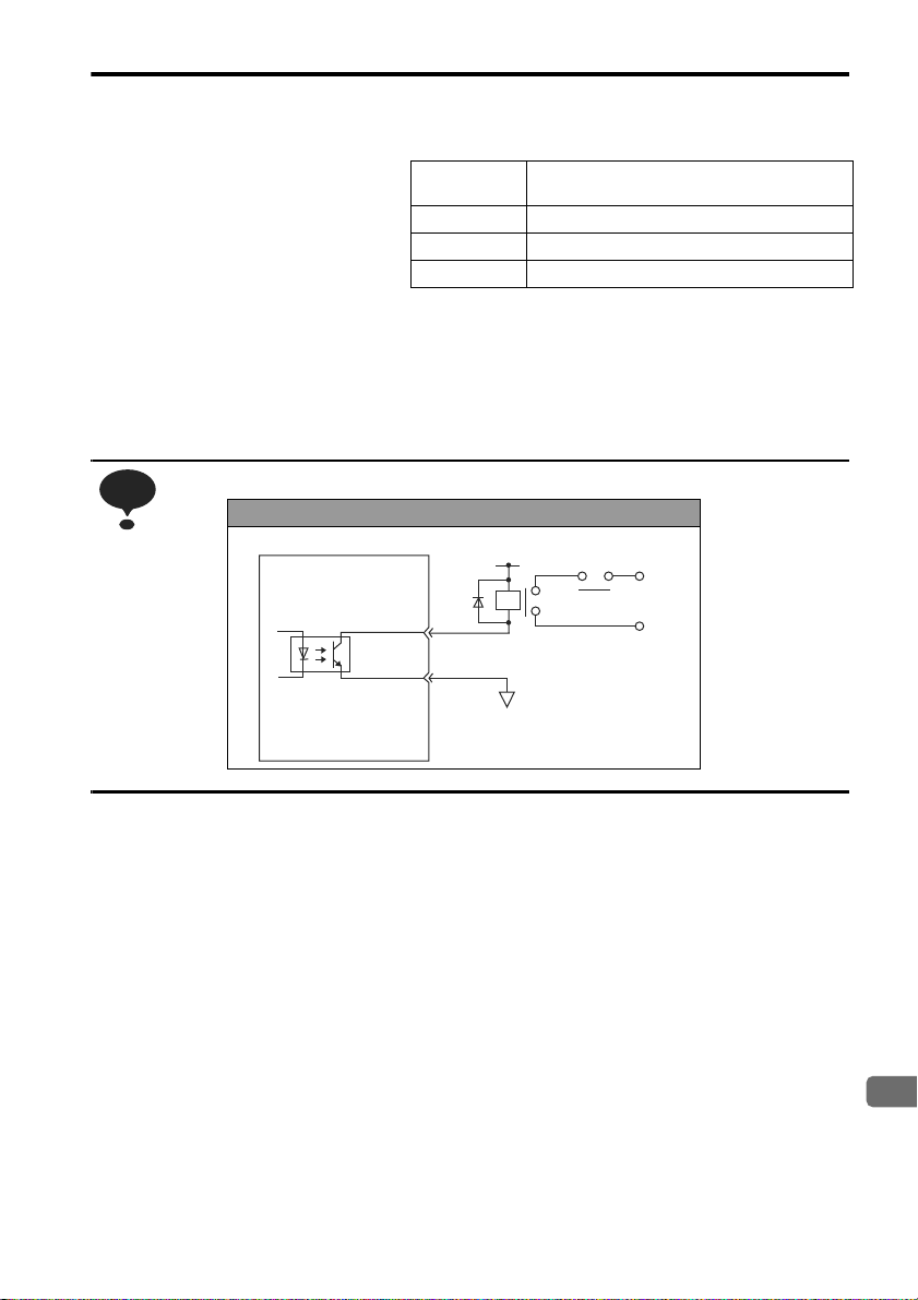
NOTE
SERVOPACK
0 V
Emergency Stop
5 VDC to 24 VDC
Note: 1. AVR1: 24 VDC power supply for brake
AVR2: 24 VDC power supply for
sequence
SW1: Power OFF switch
SW2: Power ON switch
MC1: Magnetic contactor
Ry1: Brake relay
2. The ground protection circuit is designed for ground fault inside the motor windings
while the motor is running. Therefore, it may not protect the system under the following
conditions.
• A low-resistance ground fault occurs between the main circuit cable and connector for the servomotor.
• The power supply is turned ON during a ground fault.
To configure a safer system, install an earth leakage breaker for protection against overloads and short-circuiting, or install an earth leakage breaker combined with a wiring circuit breaker for ground protection.
Configure the holding brake circuit that is to be activated upon occurrence of emergency stop.
• Parts example
Surge absorber Okaya Electric Industries Co., Ltd. CRE-50500
(Sold as: Spark Quencher)
Flywheel diode Toshiba Corporation 1NH42
Brake relay OMRON Corporation MY series
Varistor Nippon Chemi-Con Corporation TNR7V121K
Relay Circuit Example
E-25
Page 27
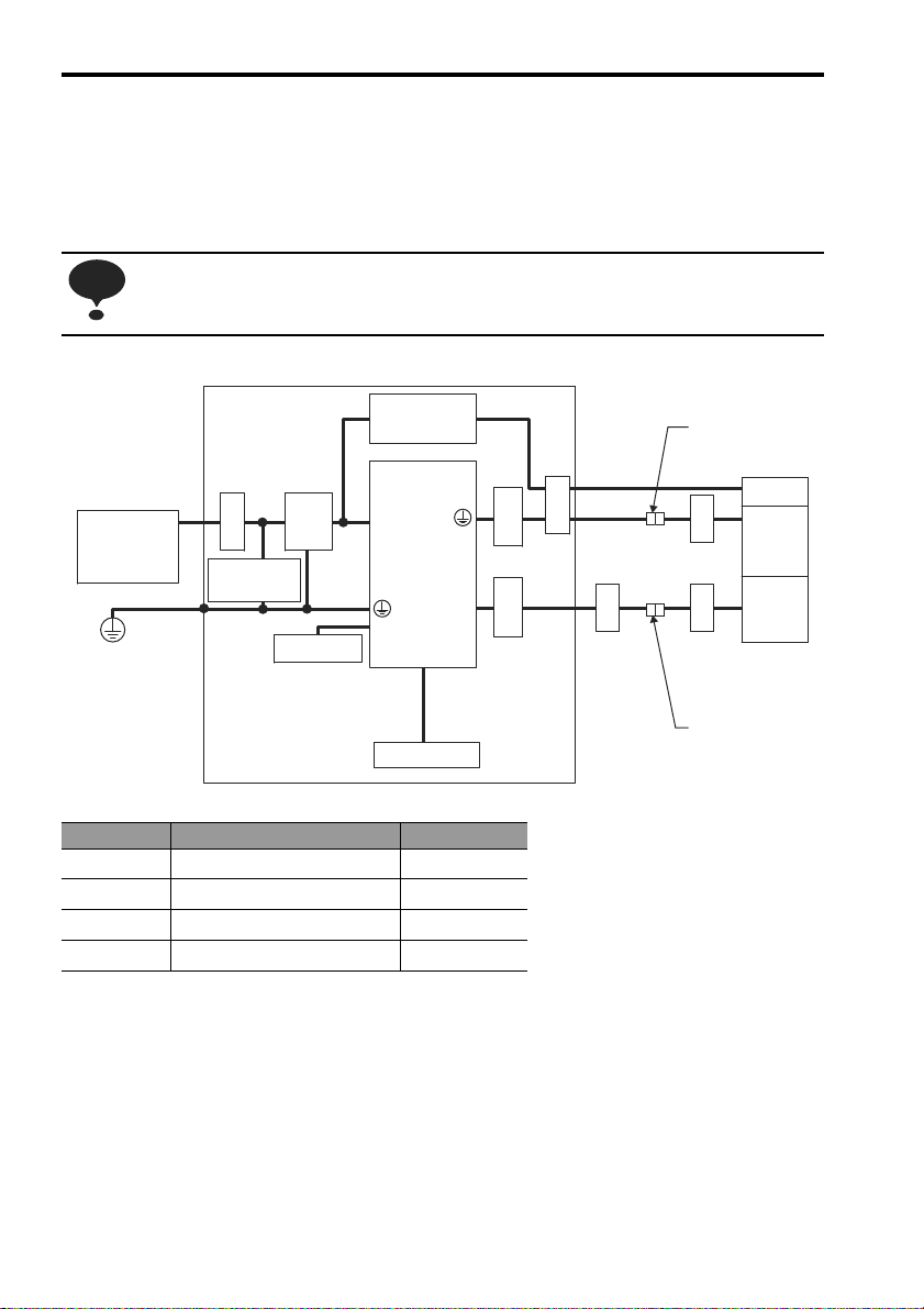
3.4 Installation and Wiring Conditions on CE Marking
NOTE
Power Supply
Single-phase
200 VAC,
100 VAC*
U, V, W
L1, L2
CN2
CN1
Ground Plate
PE
Encoder
Servo-
motor
Brake
Clamp
Noise
filter
Ferrite
core
Clamp
Surge absorber
(for lightning
surge)
Brake power
supply
Host controller
SERVOPACK
Ferrite
core
Ferrite
core
Ferrite
core
Ferrite
core
+, –
Regenerative
unit
Cable joint
Cable joint
3.4 Installation and Wiring Conditions on CE Marking
To adapt a combination of a SJME servomotor and a SJDE SERVOPACK to EMC Directives (EN55011, group 1,
class A and EN61000-6-2), the following conditions must be satisfied. After installing the SERVOPACK, do a test
run to make sure that the machine operates correctly.
The actual EMC level may differ depending on the actual system's configuration, wiring, and other
conditions.
Symbol Cable Name Specifications
c
d
e
f
* A 100 VAC power supply can be used with a SERVOPACK version 03404 or firmware version 0004 or later.
I/O Signals cable Shield cable
Servomotor Main Circuit cable Shield cable
Encoder cable Shield cable
AC Line cable Shield cable
E-26
Page 28
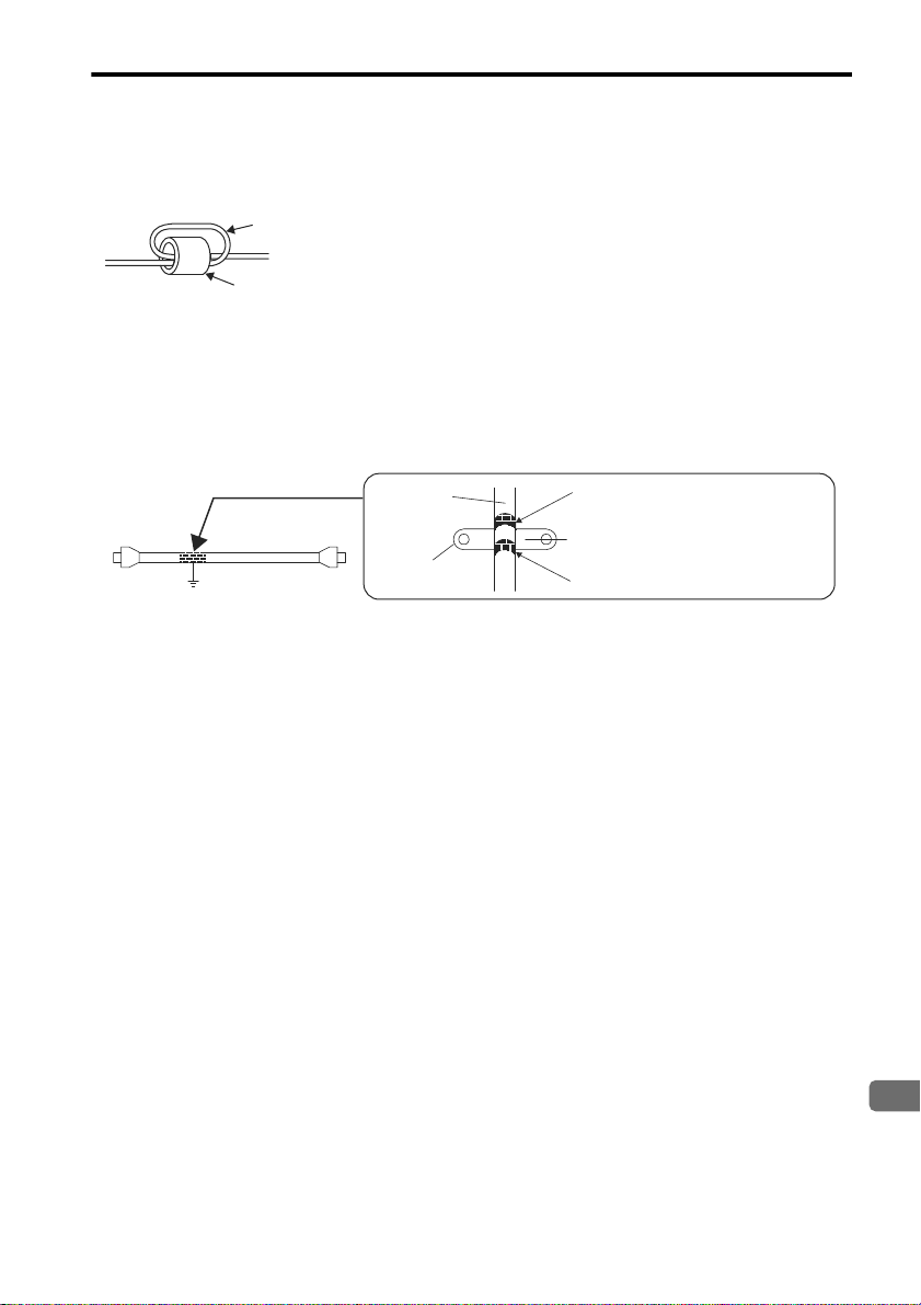
3.4 Installation and Wiring Conditions on CE Marking
English
Cable (two turns)
Ferrite core
Cable
clamp
Shield (cable sheath stripped)
Remove paint on mounting surface.
Fix and ground the cable shield
using a piece of conductive metal.
Ground plate
Host
controller
side
Cable
Attaching the Ferrite Core
Coil the motor main circuit cable (as a connection) around the ferrite core with two turns, then attach them by the
SERVOPACK. Refer to the diagram in the previous page.
Note: Recommended Ferrite-core
Model: ESD-SR-25 (Tokin. Corp.)
Fixing the Cable
Fix and ground the cable shield using a piece of conductive metal.
• Example of Cable Clamp
Shield Box
A shield box, which is a closed metallic enclosure, should be used for shielding magnetic interference. The structure
of the box should allow the main body, door, and cooling unit to be attached to the ground. The box opening should
be as small as possible.
E-27
Page 29

3.5 SERVOPACKs and Applicable Peripheral Devices
3.5 SERVOPACKs and Applicable Peripheral Devices
SERVOPACK
Capa-
Type
SJDE01APA-OY
SJDE02APA-OY
SJDE04APA-OY
SJDE08APA-OY
Manufacturer
* 1. Nominal value at the rated load. The specified derating is required to select the appropriate molded-case circuit breaker.
* 2. Cut-off characteristics (25 °C): 200 % two seconds min. and 700 % 0.01 seconds min.
Note: 1. The ground protection circuit is designed for ground fault inside the motor windings while the motor is running.
100 W
200 W
400 W
750 W
Therefore, it may not protect the system under the following conditions.
• A low-resistance ground fault occurs between the main circuit cable and connector for the servomotor.
• The power supply is turned ON during a ground fault.
To configure a safer system, install an earth leakage breaker for protection against overloads and short-circuiting,
or install an earth leakage breaker combined with a wiring circuit breaker for ground protection.
2. It is recommended to use a general-purpose circuit breaker of the rated current 200 mA or more, or a circuit
breaker for inverters (for high-frequency).
city
Power
Supply
Capacity per
SERVOPACK
kVA
0.40
0.75 X5053
1.2 8
2.2 16
−−
Current
Capacity of
Molded-case
Circuit Breaker
*1 *2
Arms
4
Current
Capacity and
Model of
External
Fuse
0KLK
015.T
(15 Arms)
0KLK
030.T
(30 Arms)
Littelfuse
Inc.
Inrush
Magnetic
Cur-
Contac-
rent
A0-p
30 HI-11J
60 HI-15J
Yaskawa
Controls
−
Co., Ltd.
tor
*3
Noise
Filter
FN2070
-6/07
FN2070
-10/07
FN2070
-16/07
Schaffner
Electronic
Surge
Absorber
xCxM-
R
601BQZ-4
Okaya
Electric
Industries
Co., Ltd.
(Sold as:
Surge
Protector)
AC
Reactor
X5052
X5054
X5056
Yaskawa
Controls
Co., Ltd.
3.6 Main Circuit Wiring
• SJDE SERVOPACKs are suitable where the power supply is less than 5000 Arms (230 V max.).
• SERVOPACKs must be used with UL-listed fuses or circuit breakers, in accordance with the National Electrical
Code (NEC).
• Use 75 °C heat-resistant copper wires or an equivalent.
3.7 SERVOPACK Main Circuit Wire Size
Cable Types
Symbol Name Allowable Conductor Temperature
PVC Normal vinyl cable −
IV 600 V vinyl cable 60 °C
HIV Temperature-resistant vinyl cable 75 °C
• Wire sizes are selected for three cables per bundle at 40 °C ambient temperature with the rated current.
• Use cables with a minimum withstand voltage of 600 V for main circuits.
• If cables are bundled in PVC or metal ducts, consider the reduction ratio of the allowable current.
• Use heat-resistant cables under high ambient or panel temperatures where normal vinyl cables will rapidly deteriorate.
• Do not use cables under continuous regenerative state.
E-28
Page 30

3.7 SERVOPACK Main Circuit Wire Size
English
Cable Size and Allowable Current
The following table shows the wire size and allowable current for three cables. Use a cable whose specifications
meet or are less than allowable current in the table.
• 600 V Heat-resistant Vinyl Cables (HIV)
AWG
Size
Nominal Cross
Section Diameter
2
mm
Configuration
Number of
2
wires/mm
Conductive
Resistance
Ω/mm
Allowable Current at Ambient Temperature
A
2
30 °C 40 °C 50 °C
20 0.5 19/0.18 39.5 6.6 5.6 4.5
− 0.75 30/0.18 26.0 8.8 7.0 5.5
18 0.9 37/0.18 24.4 9.0 7.7 6.0
16 1.25 50/0.18 15.6 12.0 11.0 8.5
14 2.0 7/0.6 9.53 23 20 16
Note: The values in the table are only for reference.
Power Supply Input Terminals (L1, L2), Motor Connection Terminals (U, V, W),
and Regenerative Unit Connection Terminals (+, -)
2
2
Terminal Symbol
HIV1.25mm
2
Wiring length:
20 m max.
HIV1.25mm
Wiring length:
0.5 m max.
2
Capacity
100
200
400
750
W
SERVOPACK Type
SJDE-01APA-OY
SJDE-02APA-OY
SJDE-04APA-OY
SJDE-08APA-OY
Note: Connectors are used for all wiring.
L1, L2 U, V, W +, -
HIV1.25 mm
HIV2.0 mm
Ground Terminal ( )
Wire Size Terminal Screw Size Tightening Torque
HIV 2.0 mm
2
min.
M4 1.2 to 1.4 Nxm
Encoder Signal Connector
Item Specifications
Cable Use Yaskawa specified wires, or shielded twisted-pair wires.
Maximum cable length 20 m
Applicable wires
Finished cable outer
diameter
AWG22 (0.33 mm
Used AWG22 for the encoder power supply and AWG26 for signal lines.
φ9 mm max.
2
) and AWG26 (0.12 mm2)
I/O Signal Connector
Item Specifications
Cable Use twisted-pair wires or shielded twisted-pair wires.
Maximum cable length 3 m
Applicable wires
Finished cable outer
diameter
AWG24 (0.2 mm
φ8 mm max.
2
), AWG26 (0.12 mm2), AWG28 (0.08 mm2)
E-29
Page 31
3.8 Wiring the Power Supply/Regenerative Unit Connector (CNA)
CAUTION
9 to 10 mm
fig A fig B
Tool Type: J-FAT-OT
(JST. Mfg Co., Ltd)
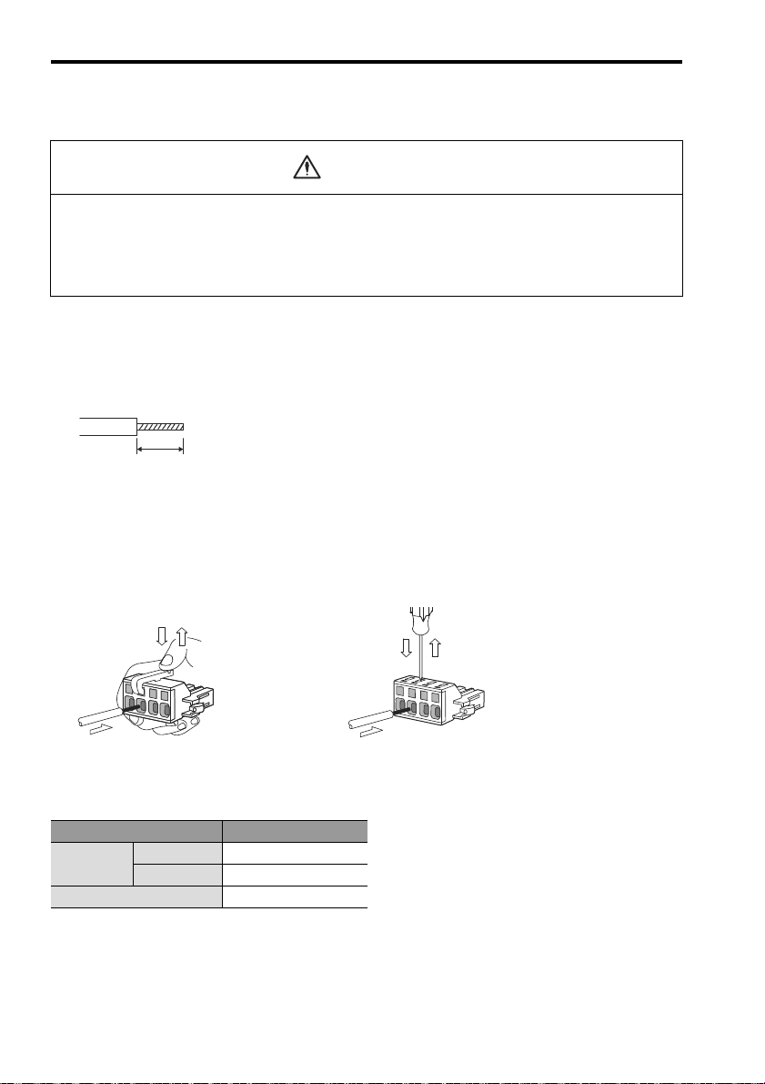
3.8 Wiring the Power Supply/Regenerative Unit Connector (CNA)
• Observe the following precautions when wiring connectors for power supply/regenerative unit and
for motor main circuit cable.
• Remove the connectors from the SERVOPACK prior to wiring.
• Insert only one wire per terminal on the connectors.
• Make sure that the core wire is not electrically shorted to adjacent core wires.
Use the following procedure when connecting the SERVOPACK to the power supply/regenerative unit connector.
1. Remove the connector from the SERVOPACK.
Make sure to remove the connector from the SERVOPACK when wiring.
2. Strip the outer coating.
Straighten the wire core with your fingers to prevent the wires from unwinding.
3. Open the wire terminal on the power supply connector housing (plug) with the tool (lever for wiring)
using the procedure shown in Fig. A or B.
• Insert the connection hook end of the provided tool into the slot as shown in Fig. A.
Tool must be purchased by the customer.
• Use a standard flat-blade screwdriver (blade width of 2.5 to 3.0 mm (0.09 to 0.12 in)). Put the blade into the
slot, as shown in Fig. B, and press down firmly to open the wire terminal.
Either the procedure shown in Fig. A or B can be used to open the wire insert opening.
4. Insert the wire core into the opening and then close the opening by releasing the tool hook or removing the screwdriver.
Wire Size
Item Wire Size
Conductor
Size
Sheath Dimension
Braided wire
Single wire
AWG14 to AWG22
φ1.6mm to φ0.65mm
φ3.8mm to φ1.7mm
E-30
Page 32

3.8 Wiring the Power Supply/Regenerative Unit Connector (CNA)
English
A
4321
N
Power supply/Regenerative Unit connector
04JFAT-SBXGF-N
(Manufactured by JST. Mfg. Co., Ltd.)
1
L2 L1
2
3
4
Power supply
Single-phase, 200 VAC, 100 VAC*
Molded-case circuit breaker
Noise filter
Magnetic contactor
AC reactor
Regenerative Unit
+(Y3)
㧙
Y4
Y5
C1
C2
CNA connector
200V
YASKAWA
SJDE- 04 APA-OY
FIL
PULSE
REF
AL1
AL2
AL3
C
N
1
C
N
2
PWR
C
0
8
9
A
B
D
E
F
4
5
3
2
6
7
1
C
0
8
9
A
B
D
E
F
4
5
3
2
6
7
1
FuseFuse
L1
L2
+
U
V
W
5. Connect the connector to the SERVOPACK.
After wiring the connector, reconnect the connector to the SERVOPACK.
* A 100 VAC power supply can be used with a SERVOPACK version 03404 or firmware version 0004 or later.
Note: 1. Pull lightly on the wires to confirm that they are securely connected.
2. Be sure that none of the insulating sheaths of the wires are caught in the springs.
Connector for Power Supply/Regenerative Unit (CNA)
Pin No. Symbol Signal Name
1L1
2L2
3+
4 −
Power supply input terminals
Regenerative unit connection
terminals
E-31
Page 33

3.9 Wiring the Servomotor Main Circuit Cable Connector (CNB)
NOTE
Servomotor main circuit cable
(for relaying)
Connector provided with
Servomotor main circuit cable
1
2
3
4
5
6
Red
White
Blue
Green/Yellow
Phase U
Phase V
Phase W
FG
Motor
Green/Yellow
CNB connector
200V
YASKAWA
SJDE- 04 APA-OY
FIL
PULSE
REF
AL1
AL2
AL3
C
N
1
C
N
2
PWR
L1
L2
+
CNA CNB
U
V
W
-
C
0
8
9
A
B
D
E
F
4
5
3
2
6
7
1
C
0
8
9
A
B
D
E
F
4
5
3
2
6
7
1
Connector for servomotor
main circuit cable
04JFAT-SAYGF-N
(JST. Mfg. Co., Ltd)
A
1
2
34
N
1
2
3
4
3.9 Wiring the Servomotor Main Circuit Cable Connector (CNB)
Wire the connector for the servomotor main circuit cable (CNB) in the same way as the connector for the power supply/regenerative unit (CNA). Refer to the previous section for details and the procedure.
• The distance between the cable for the servomotor’s main circuit and the encoder as well as the
I/O cable is 300 mm or more.
• Do not bundle or run the servomotor main circuit cable in the same duct with other cables.
• Be sure that the maximum wiring length of the servomotor main circuit cable is 20 m.
Servomotors without Brakes
YASKAWA
SJDE- 04 APA-OY
3
2
1
0
PULSE
F
E
3
2
1
0
F
FIL
E
C
N
1
C
N
2
294
L1
L2
+
-
CNA CNB
Controller
200V
4
5
6
REF
7
8
9
AL1
A
B
C
D
AL2
4
AL3
5
6
7
8
9
A
B
C
D
Separate by 300 mm or more
U
V
W
Power Supply
Note: Pin numbers are given on the connector as well. Confirm all pin numbers.
E-32
Page 34

3.9 Wiring the Servomotor Main Circuit Cable Connector (CNB)
English
SERVOPACK end
M4 crimped terminal
L
Connector (crimp type)
Receptacle: 5557-06R-210
Terminal: 5556T (Chain) or
5556TL (Loose wires)
(Molex)
Motor end
Connector (crimp type)
Receptacle: F32FSS-04V-KY
Rececontact: SF3F-01GF-P2.0 or SF3F-41GF-P2.0
(JST. Mfg. Co., Ltd.)
50mm
14
SERVOPACK Connector
(Viewed from soldered side)
123
456
Servomotor Connector
(Viewed from cable insertion side)
Lead ColorSignal NamePin No.
Red
White
Blue
Green/Yellow
Phase U
Phase V
Phase W
FG
∗
1
2
3
4
Crimped terminal
Lead ColorSignal Name
Red
White
Blue
Green/Yellow
Phase U
Phase V
Phase W
FG
Pin No.
1
2
3
4
5
6
∗:
Connect the FG pin to the grounding terminal of the SERVOPACK.
Connector provided with
Servomotor main circuit cable
CNB connector
Servomotor main circuit cable
(for relaying)
Motor
1
2
3
4
5
6
Red
White
Blue
Green/Yellow
Black
Black
Green/Yellow
Black
Varistor
Black
Phase U
Phase V
Phase W
FG
Brake
Brake
Brake relay
24 VDC
DC power
supply
200V
YASKAWA
SJDE- 04 APA-OY
FIL
PULSE
REF
AL1
AL2
AL3
C
N
1
C
N
2
PWR
L1
L2
+
CNA CNB
U
V
W
-
C
0
8
9
A
B
D
E
F
4
5
3
2
6
7
1
C
0
8
9
A
B
D
E
F
4
5
3
2
6
7
1
A
1234
N
1
2
3
4
Connector for servomotor
main circuit cable
04JFAT-SAYGF-N
(JST. Mfg. Co., Ltd)
Connection Diagram for Standard Servomotor Main Circuit Cable
If a user-prepared servomotor main circuit cable is used, refer to the following connection diagram for the standard
cable (JZSP-CHM000- Cable with Connectors on Both Ends) and wire the servomotor main circuit cable.
Servomotors with Brakes
Note: 1. Prepare a double-insulated 24-VDC power supply.
2. Connect the varistor in parallel with the 24-V power supply terminal and GND terminal
to suppress the surge voltage resulting from the holding brake turned ON and OFF.
3. Pin numbers are given on the connector as well.
E-33
Page 35

3.9 Wiring the Servomotor Main Circuit Cable Connector (CNB)
NOTE
Connector (crimp type)
Receptacle: 5557-06R-210
Terminal: 5556T (Chain) or
5556TL (Loose wires)
(Molex)
SERVOPACK end
L
50mm
Motor end
Connector (crimp type)
Receptacle: F32FSS-04V-KY
Rececontact: SF3F-01GF-P2.0 or SF3F-41GF-P2.0
(JST. Mfg. Co., Ltd.)
M4 crimped terminal
14
SERVOPACK Connector
(Viewed from soldered side)
123
456
Servomotor Connector
(Viewed from cable insertion side)
Lead ColorSignal NamePin No.
Red
White
Blue
Green/Yellow
Black
Black
Phase U
Phase V
Phase W
FG
∗1
Brake
∗2
Brake
∗2
Lead ColorSignal Name
Red
White
Blue
Green/Yellow
Black
Black
Phase U
Phase V
Phase W
FG
Brake
Brake
Pin No.
1
2
3
4
5
6
1
2
3
4
Crimped terminal
Crimped terminal
Crimped terminal
∗1:
Connect the FG pin to the grounding terminal of the SERVOPACK.
∗
2: No polarity for connection to the brake.
4. If using the servomotor to drive a vertical axis, provide a circuit to turn the holding brake
ON so that the movable section will not be pulled down by gravity when the power supply of the SERVOPACK is turned OFF.
Failures caused by incorrect wiring or wrong voltage application in the brake circuit may damage
the equipment or cause an accident resulting in death or injury.
Follow the procedures and instructions for wiring and trial operation precisely as described in this
manual.
Connection Diagram for Standard Servomotor Main Circuit Cable
If a user-prepared servomotor main circuit cable is used, refer to the following connection diagram for the standard
cable (JZSP-CHM030- Cable with Connectors on Both Ends) and wire the servomotor main circuit cable.
E-34
Page 36

3.10 Wiring the Encoder Connector (CN2)
English
Separate by
300 mm or more
Power Supply
200V
YASKAWA
SJDE- 04 APA-OY
FIL
PULSE
REF
AL1
AL2
AL3
L1
L2
+
CNA CNB
U
V
W
-
C
N
2
C
N
1
C
0
8
9
A
B
D
E
F
4
5
3
2
6
7
1
C
0
8
9
A
B
D
E
F
4
5
3
2
6
7
1
NOTE
Pin No. Signal Name
1
2
3
4
5
6
7
8
9
10
Shell
PG5V
PG0V(GND)
Phase A (+)
Phase A (-)
Phase B (+)
Phase B (-)
Phase /Z
Phase U
Phase V
Phase W
Lead Color
Red
Black
Blue
Blue/White
Yellow
Yellow/White
Purple
Gray
Green
Orange
Shield
Red
Black
Blue
Blue/White
Yellow
Yellow/White
Purple
Gray
Green
Orange
Shield
Lead ColorPin No. Signal Name
1
2
3
4
5
6
7
8
9
10
11
12
PG5V
PG0V(GND)
Phase A (+)
Phase A (-)
Phase B (+)
Phase B (-)
Phase /Z
Phase U
Phase V
Phase W
Shield
SERVOPACK Connector
(Viewed from soldered side)
Servomotor Connector
(Viewed from cable insertion side)
Shield wire
654321
12 11 10 8 79
97531
246810
SERVOPACK end
y Crimp type (Gray)
Plug and Cable Cover Set: 54599-1005
Plug Housing: 51209-1001
Crimp Terminals: 59351-8087(Chain) or
59351-8187 (Loose wires)
(Molex)
y Solder type (Black)
Shell Kit: 36310-3200-008
Receptacle: 36210-0100FD (3M)
Motor end
Receptacle: 5557-12R-210
Terminals: 5556T2 (Chain) or
5556T2L(Loose wires)
(Molex)
3.10 Wiring the Encoder Connector (CN2)
• Separate the encoder cable at least 300 mm from power lines (i.e., high-voltage lines such as the
power supply line and servomotor main circuit cable).
• Do not bundle with or run the encode cable in the same duct as power lines.
• Be sure that the maximum wiring length of the encoder cable is 20 m.
Connection Diagram for Standard Encoder Cable
If a user-prepared encoder cable is used for relaying, refer to the following connection diagram for the standard
cable (JZSP-CHP800- Cable with Connectors on Both Ends) and wire the encoder cable.
Note: Pin numbers are given on the connector as well.
E-35
Page 37

3.11 Wiring I/O Connectors
Controller
Separate by
300 mm or more
Power supply
200V
YASKAWA
SJDE- 04 APA-OY
FIL
PULSE
REF
AL1
AL2
AL3
L1
L2
+
CNA CNB
U
V
W
-
C
N
2
C
N
1
C
0
8
9
A
B
D
E
F
4
5
3
2
6
7
1
C
0
8
9
A
B
D
E
F
4
5
3
2
6
7
1
NOTE
8 9 10 11 13 1412
5432761
SERVOPACK Connector (Plug)
(Viewed from soldered side)
3.11 Wiring I/O Connectors
Note: Do not apply excessive force when connecting or disconnecting the cable or the connector.
Damage to the cable or connectors may cause the product to stop operating or malfunction.
• Separate the I/O cable at least 300 mm from power lines (i.e., high-voltage lines, such as the
power supply line and servomotor main circuit cable).
• Be sure that the maximum wiring length of the I/O cable is 3 m.
• The longer the I/O cable is, the lower the maximum transmission frequency will be.
Connection Diagram for Standard I/O Cable
If a user-prepared I/O cable is used for relaying, refer to the following connection diagram for the standard cable
(JZSP-CHI003- Cable with Connector) and wire the encoder cable.
Host controller endSERVOPACK end
Plug (14P): 10114-6000EL
Shell Kit: 10314-52A0-008
(3M)
Note: Pin numbers are given on the connector as well.
(φ5.6)
Pin
I/O Code Signal Name
No.
1 Input CW, PULS Reverse pulse,
2 Input /CW, /PULS Red
Reference pulse
3 Input CCW, SIGN Forward pulse,
4 Input /CCW, /SIGN Red
Reference sign
5 Input +24VIN External input power
Lead
Color
Orange 1 Black
Light
gray
White Black
Dot Mark
Number Color
Black
supply
6 Input /S-ON Servo ON Red
7 Output SG-COM Output signal ground Yellow Black
8 Input CLR Position deviation
9 Input /CLR Pink Black
Pulse clear
Red
10 Output PCO Phase-C signal Red
11 Output SG-PCO Phase-C signal ground Orange 2 Black
12 Output ALM Servo alarm Red
13 Output /BK Brake Light
14 Output /COIN Positioning completion Red
gray
Black
Shell −− FG −−
E-36
Page 38

3.12 Connection Examples of Input Signal
English
SERVOPACK
Photocoupler
Host Controller
1
2
9
8
4
3
/PULS
SIGN
/SIGN
CLR
/CLR
PULS
75Ω
7mA
∗
∗ޓޓ Twisted-pair wires
CN1
75Ω
75Ω
75Ω
75Ω
75Ω
5
6
3.4kΩ
/S-ON
+24VIN
0V
24VDC Power Supply
+24V
Photocoupler
1
2
9
8
4
3
/PULS
SIGN
/SIGN
CLR
/CLR
PULS
∗
Vcc
R1
i
R2
Tr1
Tr2
Tr3
R3
i
i
75Ω
75Ω
75Ω
75Ω
75Ω
75Ω
SERVOPACK
Photocoupler
7mA
CN1
5
6
3.4kΩ
/S-ON
+24VIN
0V
+24V
Examples:
When Vcc is +12V: R1 through R3=1 kΩ
When Vcc is +24V: R1 through R3=2.2 kΩ
When Vcc is +5V: R1 through R3=180 Ω
Note: The following signal logic applies for an
open-collector output.
Tr1 to Tr3 ON Equivalent to high level input.
Equivalent to low level input.Tr1 to Tr3 OFF
Host Controller
24VDC Power Supply
∗ޓޓ Twisted-pair wires
3.12 Connection Examples of Input Signal
Line Driver Output
Applicable line driver: SN75174 or MC3487 (Manufactured by Texas Instruments or equivalent)
Open-collector Output
Set the current limit resistors R1 through R3 so that the input current (i) will be within the following range.
Input Current (i) = 7 mA to 15 mA
E-37
Page 39

3.13 Connection Example of Output Signal
Photocoupler output (Per output signal)
y Max. voltage: 30VDC
y Max. current: 50m ADC
SERVOPACK
Photocoupler
10
50mA max.
+24V 0V
11
7
13
14
12
SG-PCO
ALM
/COIN
BK
SG-COM
PCO
CN1
Load
Load
Load
Load
24VDC Power Supply
NOTE
3.13 Connection Example of Output Signal
Set the load so that the output current (i) will fall within 50 mA or less.
Incorrect wiring or wrong voltage application in the output circuit may cause short-circuit.
E-38
Page 40

3.14 EMG Sequence
English
WARNING
NOTE
SERVOPACK
Servo ON
1
2
CNA
CN1
/S-ON
+24VIN
MC1
DC24V
MC1
Noise filter
MC1
MC1
SA
Power ONPower
OFF
Power supply
Single-phase 200VAC to 230VAC, Single-phase 100VAC to 115V*
50/60Hz
EMG
L1
L2
3.14 EMG Sequence
• Make sure that the emergency-stop circuit turns OFF the Servo ON signal and the power supply of
the main circuit when the EMG (emergency stop) signal turns ON.
Because of residual voltage, the servomotor rotates for a few seconds after the power supply has turned
OFF. This may result in injury or damage to the equipment. Make sure that the EMG means the stop of the
motor rotation.
• Use the power ON/OFF signals or the servo ON/OFF signals only when necessary to turn the
servomotor’s power supply ON or OFF.
Failure to observe this caution may result in unpredictable performance of the servomotor.
* A 100 VAC power supply can be used with a SERVOPACK version 03404 or firmware version 0004 or later.
E-39
Page 41

3.15 Explanation of I/O Signals
Servo ON (/S-ON)
Positioning completed (/COIN)
Clear (CLR)
Motor ON
Brake (/BK)
Sign + pulse train
Motor ON
Brake released
L
H
H
ON
ON
ON
t4
t3
t2
t1
(SIGN)
(PULS)
t1: Approx. 40 ms
t2: Approx. 130 ms
*
3
t3 ≥ 40 ms
*
1
(Motor with brake: 100 ms)
t4
≥ 20 μs
*
2
2ms max.
Alarm detection
ALM
PCO
An edge from OFF to ON
NOTE
3.15 Explanation of I/O Signals
Pulse train references are given to control the position of the servomotor. The following pulse train output forms are
supported from the host controller.
• Line driver output
• +24-V open-collector output
• +12-V open-collector output
• +5-V open-collector output
I/O Signal Timing Examples
* 1. The interval from when the servo ON signal is turned ON until the reference pulse is input
must be at least 40 ms, or the reference pulse may not be received by the SERVOPACK. If a
motor with a brake is in used, more time will be required to release the brake. Therefore,
provide an interval of at least 100 ms.
* 2. The error counter clear signal must be ON for at least 20 μs. The clear signal clears the error
counter of the SERVOPACK when the signal is turned from OFF to ON. If the reference pulse
is stops when the clear signal is turned ON, the motor will also stop at that position.
* 3. The lag time for the brake is 100 ms. Use a relay for brakes with an operating time of 30 ms or
less.
Note: 1. The maximum lag time from the time that the error or fault is detected until the time that
the alarm signal is turned ON is 2 ms.
2. If using the phase-C output signal, use an edge exactly when the signal changes from
OFF to ON. Because the wave curve is gentle, the timing to start the next sequence might
vary if not specified.
Failures caused by incorrect wiring or wrong voltage application in the brake circuit may damage
the equipment or cause an accident resulting in death or injury.
Follow the procedures and instructions for wiring and trial operation precisely as described in this
manual.
E-40
Page 42

3.15 Explanation of I/O Signals
English
Forward reference
Reverse reference
t1
t2 t3
T
SIGN
PULS
t1, t2, t3 > 3μs
τ ≥
0.65μs
(
τ/T
)
×
100 ≤ 50%
Forward reference
Reverse reference
t1
T
CW
CCW
t1 > 3μs
τ ≥
0.65μs
(
τ/T
)
×
100 ≤ 50%
Reference Pulse Signal Form Electrical Specifications Remarks
Sign + pulse train input
(SIGN + PULS signal)
Maximum reference frequency:
750 kpps (187.5 kpps for an
open-collector output)
CW pulse + CCW pulse
Sign (SIGN):
High = Forward
reference
Low = Reverse
reference
Maximum reference frequency:
750 kpps (187.5 kpps for an
open-collector output)
-
E-41
Page 43

NOTE
Select the
PULSE setting
with the rotary
switch.
Screwdriver
APA-OY
Controller
Reference pulse
APA-OY
4 Trial Operation
Failures caused by incorrect wiring or wrong voltage application in the brake circuit may damage
the equipment or cause an accident resulting in death or injury.
Follow the procedures and instructions for wiring and trial operation precisely as described in this
manual.
Use the following procedure to perform trial operation.
Step Details
1. Installation • Install the SERVOPACK and servomotor under the installation conditions.
Do not connect the servomotor shaft to the machine.
2. Wiring and PULSE Settings • Wire the power supply connector, servomotor main circuit cable,
3. LED Check • Turn ON the power and confirm that the REF indicator is lit orange
4. PULSE Reference Input 1 • Input the reference pulse from the controller, and then check on
YASK AWA
SJDE- 04 APA-OY
D
REF
C
B
E
A
F
9
0
8
1
AL1
7
PULSE
2
6
3
5
4
AL2
D
C
B
E
A
F
AL3
9
0
8
1
7
2
FIL
6
3
5
4
200V
Check that the
color of the REF
indicator changes
to orange or green.
encoder cable, and the I/O signal cable correctly following the procedures in 3 Wiring.
• If a servomotor with a brake is used, connect all signal cables
including those for the brake power supply and the relay.
• Use the PULSE rotary switch to select the type of controller’s output pulse and set the resolution of the servomotor.
Note: Use the screwdriver to change the setting
on the rotary switch. Never use the
screwdriver for any purpose other than
setting the rotary switch.
or green. If the indicator is orange, turn ON the servo ON (S-ON)
input signal and check that the color of the REF indicator changes
from orange to green.
• If the REF indicator is not orange or green, or the indicator of the
AL1, AL2 or AL3 alarm is red, refer to 6 Troubleshooting and clear
the alarm.
the number of the pulses and servomotor’s rotational direction.
Make sure the servomotor rotates in the correct direction while the
REF indicator is blinking green.
• If the servomotor does not rotate according to the reference, refer
to 6 Troubleshooting and clear the alarm.
E-42
Page 44

English
Step Details
EMERGENCY
Reference Pulse
Controller
APA-OY
Select the FIL
setting with the
rotary switch.
Screwdriver
APA-OY
5. Servomotor Shaft Coupling • Set the servomotor to servo OFF (servomotor OFF) status to turn
OFF the power. Couple the servomotor shaft to the machine under
the conditions outlined in the servomotor instructions.
6. Protective Functions • Turn ON the power, activate the servo ON (S-ON) input signal. The
machine may momentarily make a sound after the servo is turned
ON. This is due to the setting of the automatic filter in the servo
and is not an error.
• Check that all the protective functions, such as the emergency stop
and holding brake functions are working correctly.
7. PULSE Reference Input 2 • Input the reference pulse from the controller, and then check that
8. Filter Settings • If the machine vibrates or if the positioning completed signal
the machine is running in the correct direction and at the correct
rate designed by the settings. The machine may momentarily
make a sound after the machine moves. This is due to the setting
of the automatic filter in the servo and is not an error.
(/COIN) repeatedly turns ON and OFF after the servomotor stops,
turn the FIL rotary switch from 0 to 1, and then to 0 again. If the
machine still vibrates, gradually increase the setting on the FIL
rotary switch from 0 to 7 until the optimum setting is reached.
Note: Use the screwdriver to change the setting
on the rotary switch. Never use the
screwdriver for any purpose other than
setting the rotary switch.
E-43
Page 45

5.1 Requirements
CAUTION
5 Additional Functions When Digital Operator or
JunmaWin is Used
• Never run the SERVOPACK with a digital operator or JunmaWin connected.
Use a digital operator or JunmaWin only during:
• Setup, such as when the gear ratio is changed, and
• Maintenance, such as when the Monitor function is used to confirm the status.
5.1 Requirements
The following devices must be connected to the SERVOPACK to use the functions described in this chapter.
• A digital operator or personal computer running JunmaWin
• A communication unit (Model: JUSP-JC001-1)
For the operations of a digital operator, refer to Σ-V Series USER'S MANUAL Operation of Digital Operator (Manual No.: SIEP S800000 55).
5.2 List of Available Functions and Applicable SERVOPACKs
Items
Applicable SERVOPACK version
Applicable firmware version
Applicable JunmaWin version
Servomotor rotation direction
setting
Electronic gear ratio setting
Positioning completed signal
setting
Internal torque limit setting
Functions
* The digital operator cannot be connected to a Version 2 SERVOPACK (SERVOPACK: version 03202, firmware: version
0002).
Filter setting using parameters
Utility functions (alarm history
display, clearing alarm history,
JOG operation, origin search,
software version display)
Alarm display
Monitor
Version4 Version3 Version2*
03404 03303 03202
0004 0003 0002
JunmaWin
Ver.1.20 or later
Applicable Not applicable Not applicable
Applicable Applicable Not applicable
Applicable Not applicable Not applicable
Applicable Not applicable Not applicable
Applicable Not applicable Not applicable
Applicable Not applicable Not applicable
Applicable Not applicable Not applicable
Applicable Applicable Not applicable
SERVOPACK Version
JunmaWin for
SJDEP-OY
Ver.1. 00
cannot be
connected to
JunmaWin
E-44
Page 46

5.3 Servomotor Rotation Direction
English
Reverse
(CW)
Forward
(CCW)
5.3 Servomotor Rotation Direction
The servomotor rotation direction can be reversed with parameter Pn000.0 without changing the polarity of the
position reference.
The standard setting for forward rotation is counterclockwise (CCW) as viewed from the load end of the servomotor.
Forward/
Reverse
Reference
Forward
Reference
Reverse
Reference
Forward
Reference
Direction of Motor Rotation
Forward
(CCW)
Reverse
(CW)
Pn000
Parameter
n.0
The forward rotation is CCW.
[Factory setting]
n.1
The forward rotation is CW.
(reverse rotation mode)
Reverse
Reference
E-45
Page 47

5.3 Servomotor Rotation Direction
Direction Selection (rotational)
0
CCW for forward rotation.
1
CW for reverse rotation.
(reverse rotation mode)
Reserved (Do not change.)
Reserved (Do not change.)
Reserved (Do not change.)
4th 3rd 2nd 1st
digit digit digit digit
n.
Related Parameter
Parameter
No.
Basic Function Select Switch 0
Pn000
Name
Setting
Range
0010 to 0011 – 0010 After restart
Units
Factory
Setting
When
Enabled
E-46
Page 48

English
5.4 Electronic Gear
When the Electronic Gear is Not Used:
Calculate the revolutions.
1 revolution is 6 mm. Therefore, 10 ÷ 6 = 1.6666 revolutions.
Calculate the required reference pulses.
65536 pulses is 1 revolution. Therefore, 1.6666 × 65536 = 109222 pulses.
Input 109222 pulses as reference pulses.
Reference pulses must be calculated per reference. → complicated
When the Electronic Gear is Used:
The reference unit is 1μm. Therefore, to move the workpiece 10 mm (10000 μm),
1 pulse = 1 μm, so 10000 ÷ 1 = 10000 pulses.
Input 10000 pulses as reference pulses.
Calculation of reference pulses per reference is not required. → simplified
Ball screw pitch: 6 mm
Encoder resolution (16 bit) 65536
1
2
3
The section indicates the difference between using and not using an electronic gear when a workpiece is
moved 10 mm in the following configuration.
The electronic gear enables the workpiece travel distance per reference pulse input from the host controller. The
minimum unit of the position data moving a load is called a reference unit.
5.4 Electronic Gear
E-47
Page 49

5.4 Electronic Gear
Electronic gear ratio:
=
A
B
Pn210
Pn20E
=
n
m
Encoder resolution
Travel distance per load
shaft revolution (reference units)
×
NOTE
Electronic Gear Ratio
Set the electronic gear ratio using Pn20E and Pn210.
Electronic Gear Ratio (Numerator)
Pn20E
Pn210
Setting Range Setting Unit Factory Setting When Enabled
1 to 1073741824 1 4 After restart
Electronic Gear Ratio (Denominator)
Setting Range Setting Unit Factory Setting When Enabled
1 to 1073741824 1 1 After restart
If the gear ratio of the servomotor and the load shaft is given as n/m where m is the rotation of the servomotor and n
is the rotation of the load shaft,
Encoder Resolution
Encoder resolution is 65536.
Electronic gear ratio setting range: 0.01 ≤ Electronic gear ratio (B/A) ≤ 100
If the electronic gear ratio is outside this range, a parameter setting error 1 (A.040) will be output.
E-48
Page 50

English
Electronic Gear Ratio Setting Examples
Ball screw
pitch: 6 mm
16-bit encoder
Load shaft
Reference unit: 0.001 mm
16-bit encoder
Load shaft
Reference unit: 0.01°
Gear ratio:
1/10
Load shaft
Gear ratio
1/50
Reference unit: 0.005 mm
Pulley diameter:
100 mm
16-bit encoder
65536
600011
=
B
A
×
B
A
65536
36000
10
1
=
×
B
A
65536
62800
50
1
=
×
The following examples show electronic gear ratio settings for different load configurations.
Load Configuration
Ball Screw Disc Table Belt and Pulley
Step Operation
5.4 Electronic Gear
1 Check machine
specifications.
• Ball screw pitch:
6 mm
• Gear ratio: 1/1
Rotation angle per
revolution: 360°
Gear ratio: 1/10
Pulley diameter: 100 mm
(pulley circumference:
314 mm)
• Gear ratio: 1/50
2 Check the
encoder resolution.
3 Determine the
reference unit
used.
4 Calculate the
travel distance
per load shaft
revolution.
65536 (16-bit) 65536 (16-bit) 65536 (16-bit)
Reference unit: 0.001
mm (1 μm)
Reference unit: 0.01° Reference unit: 0.005
mm (5 μm)
6 mm/0.001 mm=6000 360°/0.01°=36000 314 mm/0.005 mm
=62800
(Reference unit)
5 Calculate the
electronic gear
ratio.
6 Set parameters. Pn20E: 65536 Pn20E: 655360 Pn20E: 3276800
Pn210: 6000 Pn210: 36000 Pn210: 62800
E-49
Page 51

5.5 Positioning Completed Signal
Electronic Gear Ratio Selection
0
Reference pulse resolution that is in accordance with
the setting of the rotary switch for the reference pulse
setting (PULSE).
1
Reference pulse resolution that is in accordance with
the electronic gear ratio (Pn20E/Pn210).*
Reserved. (Do not change.)
Reserved. (Do not change.)
Reserved. (Do not change.)
4th 3rd 2nd 1st
digit digit digit digit
n.
Related Parameter
Parameter
No.
Pn21B
* This parameter is only used to set the reference pulse resolution. Use the rotary switch for the reference pulse setting
(PULSE) to set the type of reference pulse. For details, refer to
and Functions.
Name Setting Range Units
Electronic Gear Function
Select Switch
0000 to 0001 – 0000 After restart
Reference Pulse Setting (PULSE) under 1.5 Part Names
Factory
Setting
5.5 Positioning Completed Signal
This signal indicates that servomotor movement has been completed during position control.
When the difference between the number of reference pulses output by the host controller and the travel distance of
the servomotor (position error) drops below the set value in the parameter, the positioning completion signal will be
output.
Use this signal to check the completion of positioning from the host controller.
Type
Output /COIN CN1-14 ON (close) Positioning has been completed.
Signal
Name
Connector
Pin Number
Setting Meaning
OFF (open) Positioning is not completed.
When
Enabled
E-50
Page 52

5.5 Positioning Completed Signal
English
Motor speed
Reference
Motor speed
/COIN
Time
Time
Time
Position error
Effective at ON (close).
Pn522
Related Parameter
Positioning Completed Width
Pn522
Setting Range Setting Unit Factory Setting When Enabled
0 to 1073741824 1 reference unit 10 Immediately
The positioning completed width setting has no effect on final positioning accuracy.
Note: If the parameter is set to a value that is too large, a positioning completed signal might be
output if the position error is low during a low speed operation. This will cause the positioning completed signal to be output continuously. If this signal is output unexpectedly, reduce
the set value until it is no longer output.
E-51
Page 53

5.6 Internal Torque Limit
V
Pn403
Pn402
V
Speed
Maximum torque
Speed
Limiting torque
No Internal Torque Limit
(Maximum Torque Can Be Output)
Internal Torque Limit
5.6 Internal Torque Limit
This function always limits maximum output torque by setting values of following parameters.
Related Parameters
Forward Torque Limit
Pn402
Pn403
The setting unit is a percentage of the rated torque.
Note: 1. The maximum torque of the servomotor is used when the set value exceeds the maximum torque.
2. If the settings of Pn402 and Pn403 are too low, the torque may be insufficient for acceleration or deceleration of
Setting Range Setting Unit Factory Setting When Enabled
0 to 800 1% 800 Immediately
Reverse Torque Limit
Setting Range Setting Unit Factory Setting When Enabled
0 to 800 1% 800 Immediately
the servomotor.
Torque waveform
E-52
Page 54

5.7 Filter Setting using Parameter
English
Start
Vibration during
operation?
Increase FIL setting with rotary
switch (FIL).
End
Satisfied with response?
End
Yes
No
Connect a digital operator or
a computer with JunmaWin.
Set the tuning-less function
(Pn170.0) to 1.
(Enable response settings
set by parameters.)
Load moment of inertia
too high?
No
Yes
Set tuning-less load level
(Pn170.3) to 0.
Set tuning-less load level
(Pn170.3) to 1.
No
Yes
Increase tuning-less rigidity
level (Pn170.2).
Satisfied with response?
End
Yes
No
Note: Set the tuning-less load level (Pn170.3) to 1 if
overshooting or low-frequency vibrations occur.
Note: Refer to Related Parameter under 5.7 Filter Setting
using Parameter.
5.7 Filter Setting using Parameter
If the machine vibrates or overshooting occurs, use the Pn170 parameter. Response can be improved by changing
the parameter setting to select a filter.
Filter Setting Procedure
E-53
Page 55

5.7 Filter Setting using Parameter
Tuning-less Function Selection
When
Enabled
0
Uses the setting of the reference filter
setting rotary switch (FIL).
After restart
1
Uses the settings in Pn170.2 and
Pn170.3.
Reserved (Do not change.)
Tuning-less Rigidity Level
Acceleration/
Deceleration
Time for step
Reference
Approx. Time
between Completing Reference and
Completing
Positioning
(Setting Time)
Description When
Enabled
0 170 ms 500 to 1000 ms
Immediately
1 85 ms 250 to 500 ms
2 80 ms 200 to 400 ms
3 70 ms 170 to 340 ms
4 65 ms 150 to 300 ms
5 60 ms 130 to 260 ms
6 50 ms 110 to 220 ms
7 45 ms 100 to 200 ms
8 40 ms 90 to 180 ms
9 36 ms 80 to 160 ms
A 33 ms 75 to 145 ms
B 30 ms 70 to 135 ms
C 28 ms 65 to 125 ms
D 26 ms 60 to 115 ms
E 24 ms 55 to 110 ms
F 22 ms 50 to 100 ms
Tuning-less Load Level
When
Enabled
0 Small load level
Immediately
1 Large load level
4th 3rd 2nd 1st
digit digit digit digit
n.
Related Parameter
Parameter
No.
Pn170
Name Setting Range Units
Tuning-less Function
0000 to 1F01 – 0700 –
Related Switch
Factory
Setting
Large filter
time
constant
(little
vibration
with a long
positioning
time)
Small filter
time
constant
(short
positioning
time)
When
Enabled
E-54
Page 56

5.8 Utility Functions
English
5.8 Utility Functions
Utility Function List
Fn No. Function Remarks
Fn000 Alarm History Display –
Fn002 JOG Operation –
Fn003 Origin Search –
Fn006 Clearing Alarm History –
Fn010 Write Prohibited Setting Cannot to be changed.
Fn012 Software Version Display –
Alarm History Display (Fn000)
This function displays the last ten alarms that have occurred in the SERVOPACK.
The latest ten alarm numbers and time stamps* can be checked.
* Time Stamps
A function that measures the ON times of the control power supply and main circuit power supply in 100-ms units
and displays the total operating time when an alarm occurs. The time stamp operates around the clock for approximately 13 years.
<Example of Time Stamps>
If 36000 is displayed,
3600000 [ms] = 3600 [s] = 60 [min] = 1 [h]
Therefore, the total number of operating hours is 1 hour.
Preparation
There are no tasks that must be performed before displaying the alarm history.
E-55
Page 57

5.8 Utility Functions
BB
− FUNCTION−
Fn012
Fn000
Fn002
Fn003
− ALARM−
0: D00 0001207196
1: 720 0000032651
2: 511 0000009043
3: −−−
BB
− ALARM−
1: 720 0000032651
2: 511 0000009043
3: −−−
4: −−−
Time stamps
Alarm Number
Alarm Sequence Number
The higher the number,
the older the alarm data.
BB
Operating Procedure
Use the following procedure.
Step Display after Operation Keys Operation
Press the Key to open the Utility
Function Mode main menu, and select
1
2
Fn000 using the or Key.
Press the Key.
The display is switched to the display of
Fn000 (alarm history display).
Press the or Key to scroll
the alarm history display.
E-56
or
Press the Key.
The display returns to the Utility Function
Mode main menu.
3
BB
Fn012
4
Fn000
Fn002
Fn003
Note: 1. If the same alarm occurs after more than one hour, the alarm will be saved. If it occurs in less than one hour, it will
not be saved.
2. The display ".---" means no alarm occurs.
3. Delete the alarm history using the parameter Fn006. The alarm history is not cleared on alarm reset or when the
SERVOPACK main circuit power is turned OFF.
4. CPF00 and CPF01 are the alarms related to digital operator, and not recorded in Alarm Data.
5. Warnings are not recorded in Alarm Data.
− FUNCTION−
Page 58

5.8 Utility Functions
English
BB
− FUNCTION−
Fn000
Fn002
Fn003
Fn006
JOG Operation (Fn002)
JOG operation is used to check the operation of the servomotor under speed control without connecting the SERVOPACK to the host controller.
Preparation
The following conditions must be met to perform a jog operation.
• All alarms must be cleared.
• The servo ON signal (/S-ON) must be OFF.
• The JOG speed must be set considering the operating range of the machine.
Set the jog speed in Pn304.
Jog Speed
Pn304
Pn305
Pn306
Setting Range Setting Unit Factory Setting When Enabled
0 to 10000
Soft Start Acceleration Time
Setting Range Setting Unit Factory Setting When Enabled
0 to 10000 1 ms 100 Immediately
Soft Start Deceleration Time
Setting Range Setting Unit Factory Setting When Enabled
0 to 10000 1 ms 100 Immediately
1 min
-1
500 Immediately
Operating Procedure
Use the following procedure. The following operation example shows when the servomotor rotates at the JOG speed
1000 min-1. The factory setting of JOG speed is 500 min-1.
Step Display after Operation Keys Operation
Press the Key to open the Utility
1
BB − JOG−
Pn304=00500
2
Un000=0 00000
Un002=0 00000
Un00D=0 0000000000
Function Mode main menu, and select
Fn002 using the
Key.
Press the
The display is switched to the execution
display of Fn002 (JOG mode operation).
or Key.
E-57
Page 59

5.8 Utility Functions
BB − JOG−
Pn304=00500
Un000=0 00000
Un002=0 00000
Un00D=0 0000000000
BB − JOG−
Pn304=01000
Un000=0 00000
Un002=0 00000
Un00D=0 0000000000
BB − JOG−
Pn304=01000
Un000=0 00000
Un002=0 00000
Un00D=0 0000000000
RUN − JOG−
Pn304=01000
Un000=0 00000
Un002=0 00000
Un00D=0 0000000000
RUN − JOG−
Pn304=01000
Un000=0 00000
Un002=0 00000
Un00D=0 0000000000
Step Display after Operation Keys Operation
Press the
Key.
3
The cursor moves to the setting side (the
right side) of Pn304 (JOG mode
operation).
4
5
6
7
BB − JOG−
Pn304=01000
8
Un000=0 00000
Un002=0 00000
Un00D=0 0000000000
Press the
or Key to set the JOG
speed to 1000 min
Press the Key.
The setting value is entered, and the
cursor moves to the parameter number
side (the left side).
Press the Key.
“RUN” is displayed in the status display,
and the servo turns ON.
Press the
servomotor at the speed 1000 min
forward direction.
Press the
servomotor at the speed 1000 min
reverse direction.
After having confirmed the correct motion
of servomotor, press the Key.
“BB” is displayed in the status display,
and the servo turns OFF.
or Key and the
-1
.
Key to rotate the
Key to rotate the
-1
in
-1
in
E-58
Page 60

5.8 Utility Functions
English
Step Display after Operation Keys Operation
Press the
BB
Fn000
9
Fn002
Fn003
Fn006
− FUNCTION−
Key.
The display returns to the Utility Function
Mode main menu.
10
After JOG operation, turn OFF the power
to the SERVOPACK and then turn ON
again.
E-59
Page 61

5.8 Utility Functions
CAUTION
For aligning the motor
shaft to the machine
Servomotor
Machine
BB
− FUNCTION−
Fn002
Fn003
Fn006
Fn010
Origin Search (Fn003)
The origin search is designed to position the origin pulse position of the incremental encoder (phase C) and to clamp
at the position.
• Perform origin searches without connecting the coupling.
This function is used when the motor shaft needs to be aligned to the machine.
Motor speed at the time of execution: 60 min
-1
Preparation
The following conditions must be met to perform the origin search.
• All alarms must be cleared.
• The servo ON signal (/S-ON) must be OFF.
Operation Procedure
Use the following procedure. The following operation example shows when the servomotor rotates
counterclockwise until the servomotor stops at the detected phase-C position.
Step Display after Operation Keys Operation
Key to open the Utility
Press the
1
BB − Z − Search−
Un000=0 00000
2
Un002=0 00000
Un003=0 0000000774
Un00D=0 0000000000
Function Mode main menu, and select
Fn003 using the
Press the Key.
The display is switched to the execution
display of Fn003 (Origin Search Mode).
or Key.
E-60
Page 62

5.8 Utility Functions
English
Un000=0 00000
Un002=0 00000
Un003=0 0000000774
Un00D=0 0000000000
RUN − Z − Search−
Un000=0 00000
Un002=0 00000
Un003=0 0000000000
Un00D=0 0000001D58
BB − Z − Search−
Step Display after Operation Keys Operation
Press the Key.
“RUN” is displayed in the status display,
3
RUN − Complete−
Un000=0 00000
Un002=0 00000
4
Un003=0 0000000000
Un00D=0 0000001D58
5
or
and the servomotor becomes servo ON
status.
Note: If the servomotor is already at the
zero position, “-Complete-” is displayed.
Key to rotate the
Press the
servomotor in forward direction. And then
stops at the phase-C position.
Note: 1. Keep pressing the key until the
servomotor stops.
2. When the origin search
completed normally,
“-Complete-” is displayed on the
right top on the screen.
When the origin search is completed,
press the Key.
“BB” is displayed in the status display,
and the servomotor becomes servo OFF
status. The display “-Complete-” changes
to “-Z-Search-.”
BB
Fn002
6
Fn003
Fn006
Fn010
7
− FUNCTION−
E-61
Press the
The display returns to the Utility Function
Mode main menu.
After origin search operation, turn OFF
the power to the SERVOPACK and then
turn ON again.
Key.
Page 63

5.8 Utility Functions
BB
Alarm History
Start : [DATA]
Return: [SET]
Data Clear
BB
Alarm History
Start : [DATA]
Return: [SET]
Data Clear
Clearing Alarm History (Fn006)
The clear alarm history function deletes all of the alarm history recorded in the SERVOPACK.
Note: The alarm history is not deleted when the alarm reset is executed or the main circuit power
supply of the SERVOPACK is turned OFF.
Preparation
There are no tasks that must be performed before clearing the alarm history.
Operating Procedure
Use the following procedure.
Step Display after Operation Keys Operation
Press the
BB
Fn003
1
Fn006
Fn010
Fn012
2
− FUNCTION−
Key to open the Utility
Function Mode main menu, and select
Fn006 using the or Key.
Key.
Press the
The display is switched to the execution
display of Fn006 (Clearing Alarm
History).
3
E-62
Key to clear the alarm
Press the
history.
During clearing, “Done” is displayed in
or
the status display. After the clearing is
completed, “BB” is displayed.
Note: Press the
Key not to clear
the alarm history. The display
returns to the Utility Function Mode
main menu.
Page 64

English
Software Version Display (Fn012)
BB
− FUNCTION−
Fn010
Fn012
Fn000
Fn002
BB − Soft Ver−
DRIVER
Ver.=0001
BB
− FUNCTION−
Fn010
Fn012
Fn000
Fn002
Select Fn012 to check the SERVOPACK software version numbers.
Preparation
There are no tasks that must be performed before the execution.
Operating Procedure
Use the following procedure.
Step Display after Operation Keys Operation
Press the key to open the Utility
1
2
3
Function Mode main menu, and select
Fn012 using the or Key.
Press the Key.
The SERVOPACK software version
number is displayed.
Press the Key.
The display returns to the Utility Function
Mode main menu.
5.8 Utility Functions
E-63
Page 65

5.9 Alarm Display
ALM1
ALM2
ALM3
ALM1
ALM2
ALM3
A
A
A
ALM1
ALM2
ALM3
A
A
A
A
A
A
A
A
A
5.9 Alarm Display
If an alarm occurs, remove the cause of the alarm, and then clear the alarm. When a digital operator is being used,
press ALARM RESET Key on the digital operator to clear the alarm. When JunmaWin is being used, click RESET
in the Alarm Display window to clear the alarm.
Alarm List
Alarm
Normal – – –
ALARM LED
Display
Alarm Code Alarm Name Alarm Reset
A.510
Speed error
A.d00
LM1
Overload
Encoder error
Voltage error
Overcurrent A.100
SERVOPACK
built-in fan
stopped
LM2
LM3
LM1
LM2
LM3
LM1
LM2
LM3
LM1
LM2
LM3
A.710
A.720
A.730
A.7AA
A.C10
A.C20
A.C50
A.C90
A.400
A.410
A.7Ab
Overspeed Available
Position Error
Pulse Overflow
Overload: High load Available
Overload: Low load Available
Dynamic Brake Overload Available
Board Overheated Available
Servo Overrun Detected Available
Incorrect Phase Detection N/A
Incorrect Polarity Detection N/A
Encoder Signal Error N/A
Overvoltage Available
Undervoltage Available
Overcurrent N/A
SERVOPACK Built-in Fan stop N/A
Available
E-64
Page 66

5.9 Alarm Display
English
ALM1
ALM2
ALM3
ALM1
ALM2
ALM3
Blinks at regular
intervals
A
A
A
Alarm
System error
Warning List
Warni ng
Servo Setup
• Rotary switch change
• Parameter change
ALARM LED
Display
Alarm Code Alarm Name Alarm Reset
A.020
A.021
A.022
A.023
A.030
A.040
A.b33
A.bF0
A.bF1
A.bF2
A.bF3
A.bF4
A.bFA
ALARM LED
Display
Parameter Error 0 N/A
Parameter Error 1 N/A
Parameter Error 2 N/A
Parameter Error 3 N/A
Main Circuit Detector Error N/A
Parameter Setting Error N/A
Current Detection Error N/A
System Alarm 0 N/A
System Alarm 1 N/A
System Alarm 2 N/A
System Alarm 3 N/A
System Alarm 4 N/A
System Alarm A N/A
Warning Code Warning Name
A.941
A.94E
Note: The alarm classification LED has priority over
the alarm LED for warning. Alarm LED for
warning will not blink until the alarm is cleared.
Setting changed for parameters
requiring restart
PULSE setting changed (rotary
switch)
LM1
Overload A.910
LM2
LM3
E-65
Overload
Page 67

5.10 Monitor
Un005 =
87654321 digit
Un006 =
87654321 digit
5.10 Monitor
Monitor List
Un Number Content of Display Unit
Un000 Motor rotating speed
Un001 Speed reference
Un002 Internal torque reference (in percentage to the rated
torque)
Un003 Rotation angle 1
Un004 Rotation angle 2 (electric angle from polarity origin) deg
Un005
Un006
Input signal monitor
Output signal monitor
*2
*3
Un007 Input reference pulse speed
Un008 Position error amount reference unit
Un009 Accumulated load ratio (in percentage to the rated torque:
effective torque in cycle of 10 s)
Un00C Input reference pulse counter reference unit
Un00D Feedback pulse counter
-1
min
-1
min
%
feedback unit
–
–
-1
min
%
feedback unit
*1
*1
* 1. 65536 pulses/rev for SJDE-APA-OY SERVOPACK.
* 2. Example of a display on the input signal monitor (Un005) is shown below. The top row indicates which signals are OFF,
and the bottom row which signals are ON. Signals that have not been defined are set to ON.
Digit Number
Input Pin
Number
1 CN1-6 /S-ON
2 to 8 – –
* 3. Example of a display on the output signal monitor (Un006) is shown below. The top row indicates which signals are
OFF, and the bottom row which signals are ON. Signals that have not been defined are set to ON.
Digit Number
Output Pin
Number
1CN1-12ALM
2CN1-13/BK
3CN1-14/COIN
4 to 8 – –
E-66
Signal Name
Signal Name
Page 68

English
Analog Output Signals that can be Monitored
−
+
+
−
+
The shaded parts in the following diagram indicate analog output signals that can be monitored.
SERVOPACK
CN 1
Speed reference Accumulated load ratio
Error
counter
Motor rotational
speed
Speed
loop
Speed
conversion
Torque
reference
Rotation angle
Current
loop
(U/V/W)
CN2
PULS
SIGN
Position reference speed
Speed
conversion
Position loop
Electronic
gear
1
Electronic
gear
Error
counter
Position error
−
5.10 Monitor
MKp
Load
ENC
E-67
Page 69

5.11 Parameter List
Direction Selection (rotational)
0
CCW for forward rotation.
1
CW for reverse rotation.
(reverse rotation mode)
Reserved (Do not change.)
Reserved (Do not change.)
Reserved (Do not change.)
4th 3rd 2nd 1st
digit digit digit digit
n.
5.11 Parameter List
Related Parameter
Parameter
No.
Basic Function Select Switch 0
Pn000
Name
Setting
Range
0010 to 0011 - 0010 After restart
Units
Factory
Setting
When
Enabled
E-68
Page 70

English
Related Parameter
Tuning-less Function Selection
When
Enabled
0
Uses the setting of the reference filter setting
rotary switch (FIL).
After restart
1
Uses the settings in Pn170.2 and Pn170.3.
Reserved (Do not change.)
Tuning-less Rigidity Level
Acceleration/
Deceleration
Time for step
Reference
Approx. Time
between Completing Reference and
Completing
Positioning
(Setting Time)
Description When
Enabled
0 170 ms 500 to 1000 ms
Immediately
1 85 ms 250 to 500 ms
2 80 ms 200 to 400 ms
3 70 ms 170 to 340 ms
4 65 ms 150 to 300 ms
5 60 ms 130 to 260 ms
6 50 ms 110 to 220 ms
7 45 ms 100 to 200 ms
8 40 ms 90 to 180 ms
9 36 ms 80 to 160 ms
A 33 ms 75 to 145 ms
B 30 ms 70 to 135 ms
C 28 ms 65 to 125 ms
D 26 ms 60 to 115 ms
E 24 ms 55 to 110 ms
F 22 ms 50 to 100 ms
Tuning-less Load Level
When
Enabled
0
Small load level
Immediately
1
Large load level
Small filter
time
constant
(short
positioning
time)
Large filter
time
constant
(little
vibration
with a long
positioning
time)
4th 3rd 2nd 1st
digit digit digit digit
n.
5.11 Parameter List
Parameter
No.
Pn170
Name Setting Range Units
Tuning-less Function
0000 to 1F01 – 0700 –
Related Switch
Factory
Setting
When
Enabled
E-69
Page 71

5.11 Parameter List
Electronic Gear Ratio Selection
0
Reference pulse resolution that is in accordance with
the setting of the rotary switch for the reference pulse
setting (PULSE).
1
Reference pulse resolution that is in accordance with
the electronic gear ratio (Pn20E/Pn210).*
Reserved. (Do not change.)
Reserved. (Do not change.)
Reserved. (Do not change.)
4th 3rd 2nd 1st
digit digit digit digit
n.
Parameter
No.
Pn20E
Pn210
Pn21B
Pn304
Pn305
Pn306
Pn402 Forward Torque Limit
Pn403 Reverse Torque Limit
Pn522
* This parameter is only used to set the reference pulse resolution. Use the rotary switch for the reference pulse setting
(PULSE) to set the type of reference pulse. For details, refer to
and Functions.
Name Setting Range Units
Electronic Gear Ratio
(Numerator)
Electronic Gear Ratio
(Denominator)
Electronic Gear Function
Select Switch
Jog Speed
Soft Start Acceleration
Time
Soft Start Deceleration
Time
Positioning Completed
Width
1 to 1073741824 1 4 After restart
1 to 1073741824 1 1 After restart
0000 to 0001 – 0000 After restart
0 to 10000
0 to 10000 1 ms 100 Immediately
0 to 10000 1 ms 100 Immediately
0 to 800 1% 800 Immediately
0 to 800 1% 800 Immediately
0 to 1073741824 1 reference
-1
1 min
unit
Reference Pulse Setting (PULSE) under 1.5 Part Names
Factory
Setting
500 Immediately
10 Immediately
When
Enabled
E-70
Page 72

5.12 Communication Unit
English
CAUTION
CN5
5.12 Communication Unit
Wiring
For the wirings, see the following figures.
• Do not frequently plug or unplug the cable.
The cable can only be connected 20 times. If the cable is connected more often, contact failure of the connector will occur and communications will be disabled.
• Do not bend the cable unless necessary.
Frequent bending may cause the cable to break.
• Do not connect the PC running JunmaWin and the digital operator to the communication unit at the
same time.
Only the JunmaWin or the digital operator will be enabled.
• Be sure that the cable connectors are correctly inserted.
If the connectors are incorrectly or loosely connected, a communications failure will occur.
• Open the connector cover on the SERVOPACK only if necessary.
Frequent opening and closing may cause the cover to break.
• Do not pull on the cable when disconnecting it from the SERVOPACK.
If the cable is disconnected incorrectly, it might be pulled out of the cable connector.
• Be sure that the cable connectors are correctly aligned.
If the connectors are incorrectly inserted, malfunction or damage to the connector pins may occur.
To make it easy to check, a red wire is used to make pin 1 on the cable.
Connecting to Digital Operator
Cable for SERVOPACK
APA-OY
R
D
C
E
F
E
B
F
A
9
0
8
1
7
2
6
3
5
4
D
C
E
B
F
A
9
0
8
1
7
2
6
3
5
4
SJDE-APA-OY
SERVOPACK
CN52
Communication Unit
CN9
JUSP-JC001-1
CN 3
SVON COIN TGON REF
CHARGE
VCMP
ALARM
RESET
JOG
SVON
READ WRITE
SERVO
DIGITAL OPERATOR JUSP-OP05A-1-E
YASKAWA
SCROLL
MODE/SET
DATA
SERVO
Digital Operator
E-71
Page 73

5.12 Communication Unit
SJDE-APA-OY
SERVOPACK
CN 3
CN9
CN52
JUSP-JC001-1
Communication Unit
Cable for SERVOPACK
Cable for PC
R
E
F
C
0
8
9
A
B
D
E
F
4
5
3
2
6
7
1
C
0
8
9
A
B
D
E
F
4
5
3
2
6
7
1
APA-OY
JunmaWin
*
Download
PC
Connecting to PC running JunmaWin
CN5
* JunmaWin software can be downloaded from http://www.e-mechatronics.com.
Connecting to SERVOPACK
1. Open the panel which is to the right of the CN1 connector on the SERVOPACK.
2. Connect the cable to the connector inside. When connecting the cable, make sure that pin 1 (red) is
bottom.
Connecting to Communication Unit
Connect the cable, making sure that pin 1 (red) is on the top.
SJDE
SERVOPACK
YASK AWA
200V
REF
C
D
B
E
A
F
9
0
8
1
AL1
7
2
6
3
5
4
AL2
C
D
B
E
A
F
AL3
9
0
8
1
7
FIL
2
6
3
5
4
C
N
1
C
N
2
PWR
L1
U
L2
V
+
W
−
CNBCNA
SJDE- 04 APA-OY
PULSE
Pin No.1 (red)
Pin No.1 (red)
Connector for PC
E-72
Communication Unit
Page 74

English
Operation
CN52
CN3
CN9
66.5
28
67
71
(4)
Unit: mm
Never run the SERVOPACK with a digital operator or JunmaWin connected.
Use a digital operator or JunmaWin only during:
• Setup, such as when the gear ratio is changed, and
• Maintenance, such as when the Monitor function is used to confirm the status.
Dimensions
5.12 Communication Unit
Specifications of Connector for PC (CN9)
Connector Specifications
Item Manufacturer Model
Board-side Hirose Electric Corporation DF11-4DP-2DS(52)(4P)
Connector-side Hirose Electric Corporation DF-4DS-2C(4P)
Connector Pin Arrangement
Pin
Number
1 /TXD I Transmitting 3 GND – GND
2 /RXD O Receiving 4 GND – GND
Symbol I/O Function
Pin
Number
Symbol I/O Function
E-73
Page 75

6.1 Alarm Indicator Lights
NOTE
AL1
AL2
AL3
AL1
AL2
AL3
6 Troubleshooting
If the servomotor does not operate correctly due to setting failures, wiring faults, or other problems, refer to this section and take corrective actions. Contact your Yaskawa representative if the problem cannot be solved by the corrective actions described here.
When taking a corrective action, turn OFF the power, remove the cause of the alarm, and then turn
ON the power again.
6.1 Alarm Indicator Lights
Alarm
Display
Alarm
Name
Speed
error
Overload Power was
Conditions at
Alarm Occur-
rence
Power was
turned ON.
Servo was
turned ON.
Servomotor
operation was
started or was
switched to
high-speed
operation.
turned ON.
Servo was
turned ON.
Cause Corrective Action
A SERVOPACK fault occurred. Replace the SERVOPACK.
Phases U, V, and W in the servomotor are wired to the wrong
terminals.
The encoder wiring is incorrect.
Malfunction occurred due to
noise interference in the
encoder wiring.
A SERVOPACK fault occurred. Replace the SERVOPACK.
Phases U, V, and W in the servomotor are wired to the wrong
terminals.
The encoder wiring is incorrect.
Malfunction occurred due to
noise interference in the
encoder wiring.
The position reference is too
large.
A SERVOPACK fault occurred. Replace the SERVOPACK.
An overload alarm was cleared
excessive number of times by
turning OFF the power.
A SERVOPACK fault occurred. Replace the SERVOPACK.
Servomotor main circuit cable
wiring is incorrect or a contact in
servomotor wiring is faulty.
Encoder cable wiring is incorrect or a contact in encoder wiring is faulty.
A SERVOPACK fault occurred. Replace the SERVOPACK.
Correct the servomotor wiring.
Take measures against noise
for the encoder wiring.
Check and correct the servomotor wiring.
Take measures against noise
for the encoder wiring.
Input the correct reference
value.
Reconsider and correct the
load, operating conditions, and
servomotor capacity.
Check and correct the servomotor wiring.
E-74
Page 76

6.1 Alarm Indicator Lights
English
AL1
AL2
AL3
Alarm
Display
Alarm
Name
Overload The servomo-
Conditions at
Alarm Occur-
rence
tor did not
rotate for a reference input
from the controller.
Normal operation.
Servo OFF
status.
Cause Corrective Action
Servomotor main circuit cable
wiring is incorrect or a contact in
servomotor wiring is faulty.
Encoder cable wiring is incorrect or a contact in the cable is
faulty.
The starting torque exceeds the
maximum torque.
A SERVOPACK fault occurred. Replace the SERVOPACK.
The effective torque continued
over the period of the rated
torque, or the starting torque
greatly exceeds the rated
torque.
Drop in power supply voltage. Make sure that the power
The servomotor coil burned out. Measure the coil resistance. If
The servomotor was operated
with the holding brake engaged.
The ambient temperature
around the servomotor
exceeded 55 °C.
The installation conditions of the
SERVOPACK are not suitable
(the SERVOPACK is influenced
by the mounting direction,
mounting space, or ambient
objects).
A SERVOPACK fault occurred. Replace the SERVOPACK.
An overload alarm was cleared
excessive number of times by
turning OFF the power.
The SERVOPACK is used with
the 100 VAC input voltage, and
the motor is trying to rotate at a
speed outside the allowable
range defined by the speed/
torque characteristic curve.
The servomotor did not stop
three seconds after the SERVOPACK is set to servo OFF
status.
Check and correct the servomotor wiring.
Reconsider and correct the
load, operating conditions, and
servomotor capacity.
Reconsider the load and operation conditions.
Reconsider the servomotor
capacity and use a servomotor
with a larger capacity.
supply voltage is within the
permissible range.
the coil burned out, replace the
servomotor.
Measure the voltage of the
brake terminals and release the
brake.
Reconsider the installation
conditions so that the ambient
temperature will be 55 °C or
less.
Reconsider and correct the
load, operating conditions, and
servomotor capacity.
Use the 200 VAC input voltage
or input the reference correctly.
Reconsider the load conditions.
Check to see if the servomotor
is being rotated by an external
force.
E-75
Page 77

6.1 Alarm Indicator Lights
AL1
AL2
AL3
AL1
AL2
AL3
Alarm
Display
Alarm
Name
Encoder
error
Voltage
error
Conditions at
Alarm Occur-
rence
Power was
turned ON or
during servomotor operation.
Power was
turned ON.
Normal operation.
Cause Corrective Action
The encoder wiring and the contact are incorrect.
Noise interference occurred due
to incorrect encoder cable specifications.
Noise interference occurred
because the wiring distance for
the encoder cable is too long.
The encoder cable is disconnected.
An zero point error occurred. Replace the servomotor.
An encoder fault occurred.
The AC power supply voltage
exceeded the permissible
range.
The power supply was turned
ON again before the power
supply to the SERVOPACK was
completely OFF.
A SERVOPACK fault occurred. Replace the SERVOPACK.
The AC power supply voltage
exceeded the permissible
range.
The servomotor speed is high
and load moment of inertia is
excessive.
The regenerative unit is not
connected or the selection of
the regenerative unit is wrong.
A SERVOPACK fault occurred. Replace the SERVOPACK.
Correct the encoder wiring.
Use twisted-pair or shielded
twisted-pair cables with a core
of at least 0.12 mm
The wiring distance must be
20 m maximum.
Replace the encoder cable.
Make sure the AC power voltage is within the specified
range.
Wait until the REF indicator is
OFF, and turn ON the power
supply again.
Make sure the AC power voltage is within the specified
range.
Reconsider the load and operation conditions.
Calculate the regenerative
energy and connect a regenerative unit with sufficient processing capacity.
2
.
E-76
Page 78

6.1 Alarm Indicator Lights
English
AL1
AL2
AL3
Alarm
Display
Alarm
Name
Overcurrent
Conditions at
Alarm Occur-
rence
Power was
turned ON.
Cause Corrective Action
Phases U, V, and W in the servomotor are wired to the wrong
terminals.
The ground wire is caught on
other terminals.
• A short circuit occurred
between ground and U, V, or
W of the servomotor main
circuit cable.
• A short circuit occurred
between phase U, V, or W of
the servomotor main circuit
cable.
The Regenerative Unit is wired
incorrectly.
A short circuit occurred between
ground and U, V, or W of the
SERVOPACK.
• A short circuit occurred
between ground and U, V, or
W of the servomotor.
• A short circuit occurred
between phase U, V, or W of
the servomotor.
The load is excessive or beyond
the capacity of regeneration
processing.
The installation conditions of the
SERVOPACK are not suitable
(the SERVOPACK is influenced
by the mounting direction,
mounting space, or ambient
heat).
The servomotor is operating in
excess of the rated output.
The built-in cooling fan of the
SERVOPACK stopped operating.
The SERVOPACK and servomotor capacities do not match
each other.
A SERVOPACK fault occurred. Replace the SERVOPACK.
The servomotor burned out. Check the balance of the
Check and correct the servomotor wiring.
Correct the servomotor circuits
or cable. Replace the servomotor.
Note: Before turning ON the
power supply, make sure
that the circuit is correctly
grounded without a short
circuit.
Check and correct the wiring.
Replace the SERVOPACK.
Replace the servomotor.
Reconsider and correct the load
and operating conditions.
Reconsider the installation conditions so that the ambient temperature will be 55 °C or less.
Reduce the load.
Replace the cooling fan.
Refer to the catalog and select
the proper combination of SERVOPACK and servomotor
capacities.
resistance between servomotor
phases. If there is any
unbalance, replace the servomotor.
E-77
Page 79

6.1 Alarm Indicator Lights
AL1
AL2
AL3
AL1
AL2
AL3
Pn20E
Pn210
0.01≤≤100
AL1
AL2
AL3
Flashing at
regular
intervals.
Alarm Display
Alarm
Name
SERVOP
ACK builtin fan
stopped.
System
error
Reference
pulse setting rotary
switch
(PULSE)
changed.
The settings
were
changed
for
parameters that
require
the power
to be
restarted.
Conditions at
Alarm Occur-
rence
Power was
turned ON or
during servomotor operation.
Power was
turned ON.
Servo was
turned ON.
Normal
operation
Power was
turned ON or
during servomotor operation.
Cause Corrective Action
The cooling fan built into the
SERVOPACK stopped.
The air inlet of the cooling
fan is blocked with dirt or
other foreign matter.
The power was turned OFF
while the parameter was
being set.
A value outside the allowable setting range was set
for the parameter.
The electronic gear ratio is
outside the setting range.
A SERVOPACK fault
occurred.
A SERVOPACK fault
occurred.
The cable for the servomotor main circuit was disconnected.
A SERVOPACK fault
occurred.
−
Refer to 7 Inspections and
replace the cooling fan.
Inspect the cooling fan.
Execute Initialize Servo of
the parameter edit function
of JunmaWin, and set the
parameter.
Reset the value to be within
the allowable setting range.
Reset the value to be within
the allowable range:
• Replace the SERVOPACK.
• Contact your Yaskawa
representative.
• Replace the SERVOPACK.
• Contact your Yaskawa
representative.
Reconsider the wiring of the
cable for the servomotor
main circuit.
• Replace the SERVOPACK.
• Contact your Yaskawa
representative.
Turn ON the power again.
(The operation of the servomotor can continue during
display of this alarm.)
E-78
Page 80

6.2 Troubleshooting for Malfunctions when Alarm Indicators Are Not Lit
English
6.2 Troubleshooting for Malfunctions when Alarm Indicators Are Not Lit
Troubleshooting for malfunctions that occur with the servomotor even though the alarm indicators do not light are
listed below. Perform the appropriate corrective actions accordingly.
: Take corrective actions for the shaded items only after turning the servo system OFF.
Problem Cause Inspection Items Corrective Action
PWR indicator does not
light when
power is
turned ON.
Servomotor
does not
rotate for reference input
from the controller.
The wiring of the power
cable is incorrect.
The wiring of the regenerative unit is incorrect.
The servo ON (/S-ON) input
is OFF.
The reference pulse settings
are incorrect.
The wiring of the servomotor
main circuit cable is
incorrect.
The wiring of the encoder
cable is incorrect
The wiring of the I/O signal
(connector CN1) is incorrect.
The power is not turned ON. Check the power supply and
Both CW input and CCW
input are ON simultaneously.
A SERVOPACK fault
occurred.
Check the power supply to
be sure it is within the permissible voltage range.
Check the wiring of the
power supply input.
Check the connection cable
for the regenerative unit is
correctly wired.
Check to see if the REF indicator is lit green.
Check to see if the REF
indicator is flashing.
Check the reference pulse
types of the controller and
the SERVOPACK.
Check the wiring. Correct the wiring.
Check the wiring of the reference pulse.
Check the reference pulse
type.
Check the voltage of the
reference pulse.
the status of PWR indicator.
Check the voltage between
the power supply terminals.
Check the wiring of the
reference pulses.
− Replace the SERVOPACK.
Set the power supply input
within the permissible power
supply voltage range.
Correct the wiring.
Replace the SERVOPACK
and the regenerative unit,
and correct the wiring.
Turn ON the servo ON signal
or wire the servomotor correctly if the REF indicator is
lit orange.
Wire the servomotor correctly
or set the pulse type of the
SERVOPACK according to
the reference pulse type of
the controller if the REF
indicator is not lit.
Set the pulse type of the
SERVOPACK according to
the reference pulse type of
the controller.
Correct the wiring.
Set the pulse type of the
SERVOPACK according to
the reference pulse type of
the controller.
Connect a resistor according
to the voltage.
Turn ON the power.
Correct the power ON circuit.
• Input either the CW pulse
signal or CCW pulse signal.
• Be sure to turn OFF all
terminals with no input
signals.
E-79
Page 81

6.2 Troubleshooting for Malfunctions when Alarm Indicators Are Not Lit
Problem Cause Inspection Items Corrective Action
Servomotor
turns for a
moment and
stops.
Servomotor
turns even
without a reference.
The motor
does not
rotate at the
speed specified by the
reference
input.
Servomotor
turns in the
wrong direction.
Servomotor
operation is
not stable.
Motor overheated
The wiring of the servomotor main circuit cable and
encoder cable is incorrect.
The reference pulse input is
not correct.
The SERVOPACK is faulty. − Replace the SERVOPACK.
The SERVOPACK is used
with the 100 VAC input voltage, and the motor is trying
to rotate at a speed outside
the allowable range defined
by the speed/torque characteristic curve.
The CW and CCW inputs
are connected backward.
The servomotor main circuit
cable or encoder cable is not
wired correctly.
Misalignment of the coupling connecting the servomotor shaft and machine,
loose screws, or load torque
changes resulting from pulley and gear engagement.
The load moment of inertia
exceeds the permissible
value of the SERVOPACK.
The connection of the pulse
signal wires is incorrect.
The ambient temperature
around the servomotor is too
high.
The ventilation is obstructed. Check to see if ventilation is
The servomotor is overloaded.
Check the order of phases U,
V, and W in the servomotor
main circuit cable and the
wiring of the encoder cable.
Check the reference pulse
type.
Check the voltage of the
reference pulse.
Check the input voltage. Reenter the correct refer-
Check the speed/torque
characteristics.
Check the reference pulse
speed.
Check the reference pulse
types of the controller and
the SERVOPACK.
Check the wiring of the servomotor main circuit cable
phases U, V, and W and the
encoder cable.
Check the coupling to the
machine system.
Operate the servomotor with
no load (i.e., disconnect the
servomotor from the
machine).
Operate the servomotor with
no load (i.e., disconnect the
servomotor from the
machine).
Check the wiring of the pulse
signal wires of the host
controller and SERVOPACK.
Check the reference pulse
types of the controller and
the SERVOPACK.
Be sure that the ambient
temperature around the servomotor is 40 °C or less.
obstructed.
Operate the servomotor with
no load (i.e., disconnect the
servomotor from the
machine).
Correct the wiring.
Set the suitable reference
pulse type.
Connect a resistor according
to the voltage.
ence.
Connect the CW pulse signal
to the CW input and the
CCW pulse signal to the
CCW input.
Correct the wiring.
Review and adjust the
machine.
Reduce the load.
Replace the servomotor and
SERVOPACK with ones with
higher capacities.
Correct the wiring.
Set the pulse type of the
SERVOPACK according to
the reference pulse type of
the controller.
Reconsider the installation
conditions so that the ambient temperature will be 40 °C
or less. Cool down the servomotor with a fan or cooler.
Provide good ventilation.
Reduce the load.
Replace the servomotor and
SERVOPACK with ones with
higher capacities.
E-80
Page 82

6.2 Troubleshooting for Malfunctions when Alarm Indicators Are Not Lit
English
Problem Cause Inspection Items Corrective Action
The holding
brake does
not work.
Servomotor
does not stop
operation
smoothly or
at all when
servo is
turned OFF.
Abnormal
noise from
Servomotor
or machine
vibrates, or
an overshoot
occurs.
The holding brake power is
turned ON.
The servomotor is overloaded.
A stop circuit fault occurred.
Mounting not secured. Check to see if there are any
Defective bearings Check for the noise and
Vibration source on the
driven machine
Noise interference due to
incorrect input signal cable
specifications.
Noise interference because
the input signal cable is
longer than the applicable
range.
Noise interference because
the encoder cable specifications are incorrect.
Noise interference because
the encoder cable is longer
than the applicable range.
Noise is entering the
encoder cable because the
sheath is damage.
Excessive noise interference on encoder cable.
FG potential varies due to
the influence of machines
such as a welder at the servomotor.
Check to see if the holding
brake power is turned ON.
Check to see if the load is
excessive or the servomotor
speed is too high.
−
loose mounting screws.
Check to see if the coupling
is misaligned.
Check to see if the coupling
is unbalanced.
vibration around the bearings.
Foreign matter, looseness, or
deformation on the machine
movable section.
Be sure that the twisted-pair
or shielded twisted-pair cable
with a core of at least
2
is used.
0.08 mm
The wiring distance must be
3 m max.
Check to see if a shielded
twisted-pair cable with a core
of at least 0.12 mm
used.
Check the length of the
encoder cable.
Check to see if the encoder
cable is damaged.
Check to see if the encoder
cable is bundled with highcurrent lines or near highcurrent lines.
Check to see if the machine
is correctly grounded
properly.
2
is being
Design the circuit so that the
holding brake is turned OFF
when the holding brake
needs to hold the load when
the servomotor comes to a
stop.
Reconsider the load
conditions and replace the
SERVOPACK.
Replace the SERVOPACK.
Tighten the mounting screws.
Align the coupling.
Balance the coupling.
If there is a fault, contact your
Yaskawa representative.
(Contact the machine manufacturer.)
Use the specified input signal
cables.
Shorten the wiring distance
for input signal cable to 3 m
or less.
Use a cable that meets the
encoder cable specifications.
The wiring distance must be
20 m or less.
Modify the encoder cable layout so the cable is not subjected to surge.
Install a surge absorber (for
lightning surge) on the
encoder cable.
Ground the machine
separately from the PG’s FG.
E-81
Page 83

6.2 Troubleshooting for Malfunctions when Alarm Indicators Are Not Lit
Problem Cause Inspection Items Corrective Action
Abnormal
noise from
Servomotor
or machine
vibrates, or
an overshoot
occurs.
Excessive vibration and
shock on the encoder.
The filter setting is improper. Check the set value on the
Vibration from the machine
occurred or servomotor
installation is incorrect.
(Mounting surface accuracy,
securing, alignment, etc.)
reference filter (FIL) rotary
switch.
Reduce vibration from the
machine or secure the servomotor.
Increase the set value on the
reference filter (FIL) rotary
switch.
E-82
Page 84

7.1 Regular Inspections
English
7 Inspections
7.1 Regular Inspections
For inspection and maintenance of the SERVOPACK, follow the inspection procedures in the following table at
least once every year. Other routine inspections are not required.
Item Frequency Procedure Comments
Exterior At least once a year Check for dust, dirt, and oil on
Loose Screws Check for loose connector
the surfaces.
screws.
7.2 Part's Life Expectancy
The following electric or electrical parts are subject to mechanical wear or deterioration over time.
If an unusual noise or vibration occurs, refer to the life expectancy table and contact your Yaskawa representative.
After examining the part in question, we will determine whether the parts should be replaced or not. When the part
has expired before the expected time, further inspection will be required.
Part Life Expectancy Comments
Cooling Fan 30,000 hours Life depends on operation conditions. Check that there is no
Note: 1. The life expectancy listed in the table is a reference period that may be affected by the
environmental and operating conditions.
2. The recommended models of the replacement cooling fans are:
SERVOPACK Model Manufacturer
SJDE-01APA-OY to
04APA-OY
SJDE-08APA-OY JZSP-CHF08-2
JZSP-CHF08-1 Sun-Wa Technos Co., Ltd.
unusual noise or vibration.
http://www.sunwa.co.jp/
Clean with cloth or compressed air.
Tighten any loose screws.
E-83
Page 85

7.3 Replacement of Cooling Fan
CAUTION
Front of
SERVOPACK
Case
Yaskawa
E
LECT
RIC
Case
Cover
APA-OY
7.3 Replacement of Cooling Fan
• Do not open the SERVOPACK case for five minutes after the LED (PWR) is turned OFF.
Residual voltage may cause electric shock.
• After turning OFF the power supply, wait 15 minutes before replacing the cooling fan.
Failure to observe this caution may result in burns because the cooling fan is hot.
• Mount the cooling fan in the correct way explained in 6.3 Replacement of Cooling Fan.
Mounting the cooling fan in the incorrect direction may result in the breakdown of the SERVOPACK.
SJDE-01APA-OY to 04APA-OY SERVOPACKs
1. Open the case of the SERVOPACK.
Insert the tip of a straight-edge screwdriver
into the three notches on the SERVOPACK
one by one and pry the case off.
2. Lift up to remove the case.
E-84
Page 86

English
3. Disconnect the cable of the cooling fan
Pick the cable up, and then pull it out.
Cooling fan
Mounting screw
Arrow on the
heatsink side
Fit the edge (
c
)
of the cooling fan
into the position (
d
)
circled here.
Arrows on the
cooling fan side
c
d
Place the cooling-fan
cable as shown here.
from the fan connector on the SERVOPAC K.
4. Unscrew the cooling fan and remove it.
5. Install the new cooling fan.
(Type: JZSP-CHF08-1)
CAUTION: Before installing the new cool-
ing fan, make sure that the
arrow on the heatsink and the
arrow on the fan face the same
direction as shown in the diagram.
6. Secure the new cooling fan on the
SERVOPACK with mounting screws.
7.3 Replacement of Cooling Fan
7. Connect the cooling-fan cable to the fan
connector on the SERVOPACK.
CAUTION: Make sure that the wiring lay-
out of the cable matches that
shown in the diagram.
8. Reattach the case and cover to the
SERVOPACK in their original positions.
E-85
Page 87

7.3 Replacement of Cooling Fan
Case
Front of
SERVOPACK
Pick the cable up,
and then pull it out.
Case
Cover
APA-OY
SJDE-08APA-OY SERVOPACKs
1. Open the case of the SERVOPACK.
Insert the tip of a straight-edge screwdriver
into the three notches on the case and the
two on the cover on the SERVOPACK one
by one and pry the case off.
2. Pull the case and the cover off of the
SERVOPACK.
3. Disconnect the cable of the cooling fan
from the fan connector on the SERVOPAC K.
E-86
Page 88

English
4. Remove the two mounting screws of
Cooling fan
Mounting screws
C
Diagram A
Diagram B
C
Make sure the direction
of the arrows on the fan
is the same as this diagram.
the cooling fan.
5. Install the new cooling fan.
Thread the cooling-fan cable through
the opening ( ) as shown in the diagram A.
CAUTION: Make sure that the arrow on
the heatsink and the arrow on
the fan face the same direction
as shown in the diagram B.
7.3 Replacement of Cooling Fan
6. Secure the fan on the SERVOPACK
with mounting screws.
E-87
Page 89

7.3 Replacement of Cooling Fan
Place the cooling-fan
cable as shown here.
H 10
J
M
LCBON
43
H 10
J
M
LCBON
43
7. Turn the SERVOPACK over, and then
connect the cooling-fan cable to the fan
connector on the SERVOPACK.
CAUTION: Make sure that the wiring lay-
out of the cable matches that
shown in the diagram.
8. Reattach the case and cover to the
SERVOPACK in their original positions.
E-88
Page 90

8.1 Specifications
English
8 Specifications
8.1 Specifications
SERVOPACK model SJDE- 01APA-OY 02APA-OY 04APA-OY 08APA-OY
Max. applicable servomotor capacity
[kW]
Continuous output current [Arms] 0.84 1.1 2.0 3.7
Instantaneous max. output current
[Arms]
Input power
supply
(for main
circuit and
control circuit)
Power loss at rated
output [W]
Input control method Capacitor-input type, single-phase full-wave rectification with resis-
Output control method PWM control, sine wave power driven system
Feedback Analog output encoder
Allowable load inertia [kgm
Leakage current
Input signal for
reference
Designated pulse
type, pulse
resolution and pulse
connection method
with PULSE switch.
I/O Signals
Clear input signal Clears the positioning error when turned from OFF to ON.
Servo ON input signal Turns the servomotor on or off.
Alarm output signal OFF if an alarm occurs.
Brake output signal External signal to control brakes.
Voltage
Frequency 50/60Hz ± 5%
Capacity at
rated output
[kVA]
200 VAC
100 VAC*
200 VAC
100 VAC*
200 VAC
100 VAC*
2
]* 0.6×10
Powersupply
frequency
High
frequency
Pulse type Select one of the following signals:
Pulse
resolution,
pulse connection
method
0.1 0.2 0.4 0.75
2.5 3.3 6.0 11.1
Single-phase 200 V to 230 VAC, +10% to -15%
Single-phase 100 V to 115 VAC, +10% to -15%
0.40 0.75 1.2 2.2
0.20 0.38 0.60 1.1
14 16 24 35
781217.5
tance to prevent inrush currents.
-4
5 mA or less
2.5 A0-p Motor cable length: 20 m max.
1. CCW + CW
2. Sign + pulse train
3. CCW + CW (logic reversal)
4. Sign + pulse train (logic reversal)
Select one of the following signals:
1. 1000 pulses/rev (Open collector/line driver) 75 kpps max.
2. 2500 pulses/rev (Open collector/line driver) 187.5 kpps max.
3. 5000 pulses/rev (Line driver) 375 kpps max.
4. 10000 pulses/rev (Line driver) 750 kpps max.
Note: OFF for 2s when power is turned ON.
Turn ON to release the brake.
3×10
-4
5×10
-4
10×10
-4
E-89
Page 91

8.2 Torque-Motor Speed Characteristics
NOTE
SERVOPACK model SJDE- 01APA-OY 02APA-OY 04APA-OY 08APA-OY
Positioning completed output
signal
ON if the current position is equal to the reference position ±10
pulses. External signal to control brakes.
Origin output signal ON if the motor is at the origin. (Width: 1/500 rev)
I/O Signals
Note: Use the pulse edge that changes the signal
from OFF to ON.
Dynamic brake (DB) Operated at main power OFF, servo alarm, servo OFF.
(OFF after motor stops; ON if the motor power is off.)
Regenerative processing Optional
(If the regenerated energy is too large, install a regenerative unit.)
LED display 5 (PWE, REF, AL1, AL2, AL3)
Built-in functions
Reference filter Select one of eight levels with FIL switch.
Cooling method Forced cooling (built-in fan)
* A 100 VAC power supply can be used with a SERVOPACK version 03404 or firmware version 0004 or later.
When a 100 VAC power supply is used, reduced ratings are applied. For details, refer to 8.2 Torque-Motor Speed Charac-
teristics.
Use the input power supply within the specified voltage range: 200 VAC to 230 VAC or 100 VAC to
115 VAC
8.2 Torque-Motor Speed Characteristics
A: Continuous Duty Zone B: Intermittent Duty Zone
SJME-01A SJME-02A SJME-04A SJME-08A
5000
)
4000
-1
3000
2000
A
1000
Motor speed (min
0
0 0.25 1.000.750.50
B
Torque (
) Torque (
N㨯m
Note: 1. The characteristics of the intermittent duty zone differ depending on the supply voltages.
The solid and dotted lines of the intermittent duty zone indicate the characteristics when
a servomotor runs with the following combinations:
• The solid line: With a single-phase 200 V SERVOPACK
• The dotted line: With a single-phase 100 V SERVOPACK
2. When the effective torque is within the rated torque, the servomotor can be used within
the intermittent duty zone.
3. When the main circuit cable length exceeds 20 m, note that the intermittent duty zone of
the To rqu e -Motor Speed Characteristics will shrink as the line-to-line voltage drops.
)
-1
Motor speed (min
5000
4000
3000
2000
1000
0
A
0 0.5 2.01.51.0
5000
)
4000
-1
3000
2000
1000
B
) Torque (
N㨯m
Motor speed (min
0
0123 4
5000
)
4000
-1
3000
A
B
) Torque (
N㨯m
2000
A
1000
Motor speed (min
0
02 4 68
N㨯m
B
)
E-90
Page 92

8.3 Overload Protection Characteristics
English
NOTE
1000
100
10
1
100 150 200 250 300
Motor torque (%)
Time (s)
SJME-01 100W)
Example: If the Servomotor torque is 300 %,
an overload alarm will occur in
approximately two seconds.
1000
100
10
1
100
150 200 250 300
Motor torque (%)
SJME-02 200W) to SJME-08(750W)
Time (s)
8.3 Overload Protection Characteristics
The SERVOPACK provides a function to protect the servomotor and SERVOPACK from overloads.
• If an overload alarm occurs, remove the cause of the alarm and wait for at least one minute. Turn
ON the servomotor again after the servomotor has cooled sufficiently. If the operation of the servomotor is repeated within a short time, the servomotor coil may burn out.
• Use a correct combination of the SERVOPACK and servomotor.
• Overload protection characteristics are the values used when the motor attached to the aluminum heatsink [250 mm × 250 mm × 6 mm (23.62 in × 23.62 in × 0.24 in)] at the ambient temperature of 40 °C (104 °F). Make sure to use the SERVOPACK in the recommended operating
conditions.
• When using SERVOPACKs with a 100 VAC power supply, depending on the motor speed, an
overload alarm may occur even if values are within the allowable range for the overload protection characteristics shown in the following figures.
The overload protection characteristics are shown below.
Note: The servomotor torque is given as a percentage of the rated torque.
E-91
Page 93

Revision History
MANUAL NO.ޓTOMP C710806 06A
Published in China October 201010-10
Date of
publication
Date of original
publication
The revision dates and numbers of the revised manuals are given on the bottom of the back cover.
Date of
Publication
October 2010
WEB
Rev.
Rev.
No.
–– –
Section Revised Content
No.
First edition
Page 94

AC SERVOPACK
JUNMA Series
INSTRUCTIONS
IRUMA BUSINESS CENTER (SOLUTION CENTER)
480, Kamifujisawa, Iruma, Saitama 358-8555, Japan
Phone 81-4-2962-5151 Fax 81-4-2962-6138
YASKAWA AMERICA, INC.
2121 Norman Drive South, Waukegan, IL 60085, U.S.A.
Phone (800) YASKAWA (800-927-5292) or 1-847-887-7000 Fax 1-847-887-7310
YASKAWA ELETRICO DO BRASIL LTDA.
Avenida Fagundes Filho, 620 Sao Paulo-SP CEP 04304-000, Brazil
Phone 55-11-3585-1100 Fax 55-11-5581-8795
YASKAWA EUROPE GmbH
Hauptstraβe 185, Eschborn 65760, Germany
Phone 49-6196-569-300 Fax 49-6196-569-398
YASKAWA ELECTRIC UK LTD.
1 Hunt Hill Orchardton Woods Cumbernauld, G68 9LF, United Kingdom
Phone 44-1236-735000 Fax 44-1236-458182
YASKAWA ELECTRIC KOREA CORPORATION
7F, Doore Bldg. 24, Yeoido-dong, Yeoungdungpo-gu, Seoul 150-877, Korea
Phone 82-2-784-7844 Fax 82-2-784-8495
YASKAWA ELECTRIC (SINGAPORE) PTE. LTD.
151 Lorong Chuan, #04-01, New Tech Park 556741, Singapore
Phone 65-6282-3003 Fax 65-6289-3003
YASKAWA ELECTRIC (SHANGHAI) CO., LTD.
No.18 Xizang Zhong Road. 17F, Harbour Ring Plaza Shanghai 200001, China
Phone 86-21-5385-2200 Fax 86-21-5385-3299
YASKAWA ELECTRIC (SHANGHAI) CO., LTD. BEIJING OFFICE
Room 1011, Tower W3 Oriental Plaza, No.1 East Chang An Ave.,
Dong Cheng District, Beijing 100738, China
Phone 86-10-8518-4086 Fax 86-10-8518-4082
YASKAWA ELECTRIC TAIWAN CORPORATION
9F, 16, Nanking E. Rd., Sec. 3, Taipei 104, Taiwan
Phone 886-2-2502-5003 Fax 886-2-2505-1280
YASKAWA ELECTRIC CORPORATION
In the event that the end user of this product is to be the military and said product is to be employed in any weapons systems or the manufacture
thereof, the export will fall under the relevant regulations as stipulated in the Foreign Exchange and Foreign Trade Regulations. Therefore, be sure to
follow all procedures and submit all relevant documentation according to any and all rules, regulations and laws that may apply.
Specifications are subject to change without notice for ongoing product modifications and improvements.
© 2010 YASKAWA ELECTRIC CORPORATION. All rights reserved.
MANUAL NO. TOMP C710806 06A
Published in China October 2010 10-10
10-10-4
 Loading...