

YASKAWA JEPMC-BUB3003-E, MP3200, JEPMC-BUB3005-E, JEPMC-BUB3008-E, JEPMC-PSD3012-E User Manual
...Page 1
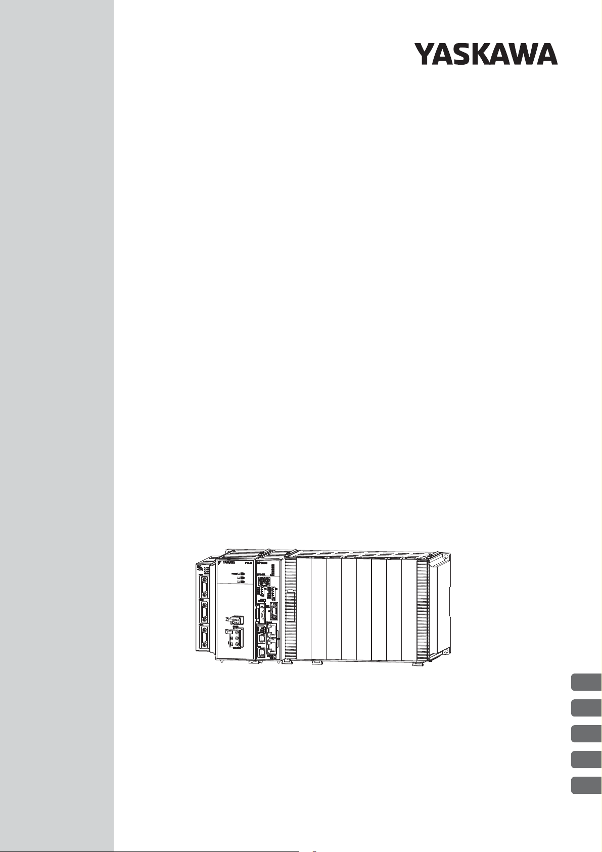
Machine Controller MP3000 Series
MP3200
USER’S MANUAL
Power Supply Unit model: JEPMC-PSA3012-E or JEPMC-PSD3012-E
CPU Unit model: JEPMC-CP3201-E or JEPMC-CP3202-E
Base Unit model: JEPMC-BUB3003-E, JEPMC-BUB3005-E, or JEPMC-BUB3008-E
Rack Expansion Interface Unit model: JEPMC-EXU3001-E or JEPMC-EXU3002-E
MANUAL NO. SIEP C880725 10D
Introduction
Appearances and Parts
CPU Unit Functionality
Specifications
External Dimensions
1
2
3
4
5
Page 2

Copyright © 2011 YASKAWA ELECTRIC CORPORATION
All rights reserved. No part of this publication may be reproduced, stored in a retrieval system, or transmitted, in any form, or by any means, mechanical, electronic, photocopying,
recording, or otherwise, without the prior written permission of Yaskawa. No patent liability is assumed with respect to the use of the information contained herein. Moreover,
because Yaskawa is constantly striving to improve its high-quality products, the information contained in this manual is subject to change without notice. Every precaution has been
taken in the preparation of this manual. Nevertheless, Yaskawa assumes no responsibility
for errors or omissions. Neither is any liability assumed for damages resulting from the use
of the information contained in this publication.
Page 3

About this Manual
This manual describes the specifications and system configuration of MP3200 Machine Controllers and the
functionality of the CPU Units.
Read this manual carefully to ensure the correct usage of the Machine Controller and apply the Machine Controller to control your manufacturing system.
Keep this manual in a safe place so that it can be referred to whenever necessary.
Using this Manual
Basic Terms
Unless otherwise specified, the following definitions are used:
Basic Terms Meaning
MP2000 A Machine Controller in the MP2000 Series
MP3000 A Machine Controller in the MP3000 Series
MPE720 The Engineering Tool or a personal computer running the Engineering Tool
PLC A Programmable Logic Controller
MP3200
Motion Control Function Modules
Communications Function Modules
A generic name for the Power Supply Unit, CPU Unit, Base Unit, and Rack
Expansion Interface Unit
The Function Modules in the Motion Modules and the Function Modules in the
SVC32 or SVR32 built into the CPU Units.
The Function Modules in the Communications Modules and the Function Modules in
the 218IFD built into the CPU Units.
MPE720 Engineering Tool Version Number
In this manual, the operation of MPE720 is described using screen captures of MPE720 version 7.
Indication of Reverse Signals
In this manual, the names of reverse signals (ones that are valid when low) are written with a forward slash (/)
before the signal name, as shown in the following example:
Notation Examples
•S-ON
•P-CON
= /S-ON
= /P-CON
Terms Used to Describe “Torque”
Although the term “torque” is commonly used when describing rotary Servomotors and “force” is used when
describing linear Servomotors, this manual uses “torque” when describing either one (excluding parameter
names).
iii
Page 4

Important
Note
Example
Information
Terms
Copyrights
• MECHATROLINK is a trademark of the MECHATROLINK Members Association.
• DeviceNet is a registered trademark of the ODVA (Open DeviceNet Venders Association).
• PROFIBUS is a trademark of the PROFIBUS User Organization.
• Ethernet is a registered trademark of the Xerox Corporation.
• Other product names and company names are the trademarks or registered trademarks of the respective company. “TM” and the
®
mark do not appear with product or company names in this manual.
Visual Aids
The following aids are used to indicate certain types of information for easier reference.
Indicates precautions or restrictions that must be observed.
Indicates alarm displays and other precautions that will not result in machine damage.
Indicates items for which caution is required or precautions to prevent operating mistakes.
Indicates operating or setting examples.
Indicates supplemental information to deepen understanding or useful information.
Indicates definitions of difficult terms or terms that have not been previously explained in this
manual.
iv
Page 5

Related Manuals
The following table lists the related manuals. Refer to these manuals as required.
Be aware of all product specifications and restrictions to product application before you attempt to use any
product.
Category Manual Name Manual Number Contents
Describes the functions of the MP2000/
MP3000-series Machine Controllers and
the procedures that are required to use the
Machine Controller, from installation and
connections to settings, programming,
trial operation, and debugging.
Describes troubleshooting an MP3000series MP3200 Machine Controller.
Describes the functions, specifications,
and application methods of the MP2200
Machine Controller.
Describes the functions, specifications,
operating methods, maintenance, inspections, and troubleshooting of the
MP2000-series MPU-01 Multi-CPU
Module.
Describes the specifications, system configuration, and communications connection methods for the Ethernet
communications that are used with an
MP3000-series Machine Controller.
Provides information on the Communications Modules that can be connected to
an MP2000-series Machine Controller
and describes the communications methods.
Describes the specifications and communications methods for the FL-net Communications Module that can be
connected to an MP2000-series Machine
Controller.
Describes the specifications and communications methods for the EtherNet/IP
Communications Module that can be
connected to an MP2000-series Machine
Controller.
Describes the specifications and communications methods for the CompoNet
Communications Module that can be
connected to an MP2000-series Machine
Controller.
Continued on next page.
Basic functionality
Communications functionality
Machine Controller MP2000/MP3000
Series
Machine Controller System
Setup Manual
Machine Controller MP3000 Series
MP3200 Troubleshooting Manual
Machine Controller MP2200
User’s Manual
Machine Controller MP2000 Series
MPU-01 Multi-CPU Module
User’s Manual
Machine Controller MP3000 Series
Communications
User’s Manual
Machine Controller MP2000 Series
Communication Module
User’s Manual
Machine Controller MP2000 Series
262IF-01 FL-net Communication Module
User’s Manual
Machine Controller MP2000 Series
263IF-01 EtherNet/IP Communication
Module User’s Manual
Machine Controller MP2000 Series
265IF-01 CompoNet Module
User’s Manual
SIEP C880725 00
SIEP C880725 01
SIEP C880700 14
SIEP C880781 05
SIEP C880725 12
SIEP C880700 04
SIEP C880700 36
SIEP C880700 39
SIEP C880700 44
v
Page 6

Category Manual Name Manual Number Contents
Describes the specifications, system con-
Motion control functionality
Programming
Engineering
Tools
I/O Modules
Machine Controller MP3000 Series
Motion Control
User’s Manual
Machine Controller MP2000 Series
Pulse Output Motion Module PO-01
User’s Manual
Machine Controller MP2000 Series
SVA-01 Motion Module
User’s Manual
Machine Controller MP2000 Series
Built-in SVB/SVB-01 Motion Module
User’s Manual
Machine Controller MP2000 Series
SVC-01 Motion Module
User’s Manual
Machine Controller MP3000 Series
Ladder Programming Manual
Machine Controller MP3000 Series
Motion Programming Manual
Machine Controller MP2000/MP3000
Series
MPLoader Ver. 4
User’s Manual
Machine Controller MP2000/MP3000
Series
MPLoad Maker Version 4
User’s Manual
Machine Controller MP2000/MP3000
Series
Engineering Tool
MPE720 Version 7
User’s Manual
Machine Controller MP2000 Series
Analog Input/Analog Output Module
AI-01/AO-01 User’s Manual
Machine Controller MP2000 Series
Counter Module CNTR-01
User’s Manual
Machine Controller MP2000 Series
I/O Module
User’s Manual
SIEP C880725 11
SIEP C880700 28
SIEP C880700 32
SIEP C880700 33
SIEP C880700 41
SIEP C880725 13
SIEP C880725 14
SIEP C880761 01
SIEP C880761 02
SIEP C880761 03
SIEP C880700 26
SIEP C880700 27
SIEP C880700 34
figuration, and operating methods for the
SVC32/SVR32 Motion Function Modules that are used in an MP3000-series
Machine Controller.
Describes the functions, specifications,
and operating methods of the MP2000series PO-01 Motion Module.
Describes the functions, specifications,
and operating methods of the MP2000series SVA-01 Motion Module.
Describes the functions, specifications,
and operating methods of the MP2000series Motion Module (built-in Function
Modules: SVB, SVB-01, and SVR).
Describes the functions, specifications,
and operating methods of the MP2000series SVC-01 Motion Module.
Describes the ladder programming specifications and instructions of MP3000series Machine Controller.
Describes the motion programming and
sequence programming specifications
and instructions of MP3000-series
Machine Controller.
Describes how to install and operate the
MPLoader.
Describes how to install and operate the
MPLoad Maker.
Describes how to operate MPE720 version 7.
Describes the functions, specifications,
and operating methods of the AI-01 and
AO-01 I/O Modules for MP2000-series
Machine Controllers.
Describes the functions, specifications,
and operating methods of the CNTR-01
Counter Module for MP2000-series
Machine Controllers.
Describes the functions, specifications,
and operating methods of the LIO-01,
LIO-02, LIO-04, LIO-05, LIO-06, and
DO-01 I/O Modules for MP2000-series
Machine Controllers.
Continued from previous page.
Continued on next page.
vi
Page 7

Continued from previous page.
Category Manual Name Manual Number Contents
Describes the functions, specifications,
MECHATROLINK
I/O
MECHATROLINK-III Compatible I/O
Module
User’s Manual
Machine Controller MP900/MP2000
Series
Distributed I/O Module
User’s Manual
MECHATROLINK System
SIEP C880781 04
SIE-C887-5.1
operating methods, and MECHATROLINK-III communications for the
Remote I/O Modules for MP2000/
MP3000-series Machine Controllers.
Describes MECHATROLINK distributed
I/O for MP900/MP2000-series Machine
Controllers.
vii
Page 8
CAUTION
PROHIBITED
MANDATORY
WARNING
Safety Precautions
The following signal words and marks are used to indicate safety precautions in this manual.
Information marked as shown below is important for safety. Always read this information and heed the precautions that are provided.
WARNING
The following precautions are for storage, transportation, installation, wiring, operation, maintenance, inspection, and disposal. These precautions are important and must be observed.
Indicates precautions that, if not heeded, could possibly result in loss of life or
serious injury.
Indicates precautions that, if not heeded, could result in relatively serious or
minor injury, or property damage.
If not heeded, even precautions classified as cautions ( ) can lead to
serious results depending on circumstances.
Indicates prohibited actions. For example, indicates prohibition of open
flame.
Indicates mandatory actions. For example, indicates that grounding is
required.
CAUTION
General Precautions
• The installation must be suitable and it must be performed only by an experienced technician.
There is a risk of electrical shock or injury.
• Before connecting the machine and starting operation, make sure that an emergency stop procedure has been provided and is working correctly.
There is a risk of injury.
• Do not approach the machine after a momentary interruption to the power supply. When power
is restored, the Machine Controller and the device connected to it may start operation suddenly.
Provide safety measures in advance to ensure human safety when operation restarts.
There is a risk of injury.
• Do not touch anything inside the Machine Controller.
There is a risk of electrical shock.
• Do not remove the front cover, cables, connector, or options while power is being supplied.
There is a risk of electrical shock, malfunction, or damage.
• Do not damage, pull on, apply excessive force to, place heavy objects on, or pinch the cables.
There is a risk of electrical shock, operational failure of the product, or burning.
• Do not attempt to modify the Machine Controller in any way.
There is a risk of injury or device damage.
viii
Page 9

Storage and Transportation
• Do not store the Machine Controller in any of the following locations.
• Locations that are subject to direct sunlight
• Locations that are subject to ambient temperatures that exceed the storage conditions
• Locations that are subject to ambient humidity that exceeds the storage conditions
• Locations that are subject to rapid temperature changes and condensation
• Locations that are subject to corrosive or inflammable gas
• Locations that are subject to excessive dust, dirt, salt, or metallic powder
• Locations that are subject to water, oil, or chemicals
• Locations that are subject to vibration or shock
There is a risk of fire, electrical shock, or device damage.
• Hold onto the main body of the Machine Controller when transporting it.
Holding the cables or connectors may damage them or result in injury.
• Do not overload the Machine Controller during transportation. (Follow all instructions.)
There is a risk of injury or an accident.
• Never subject the Machine Controller to an atmosphere containing halogen (fluorine, chlorine,
bromine, or iodine) during transportation.
There is a risk of malfunction or damage.
• If disinfectants or insecticides must be used to treat packing materials such as wooden frames,
pallets, or plywood, the packing materials must be treated before the product is packaged, and
methods other than fumigation must be used.
Example: Heat treatment, where materials are kiln-dried to a core temperature of 56°C for 30 minutes or
more.
If the electronic products, which include stand-alone products and products installed in machines, are
packed with fumigated wooden materials, the electrical components may be greatly damaged by the
gases or fumes resulting from the fumigation process. In particular, disinfectants containing halogen,
which includes chlorine, fluorine, bromine, or iodine can contribute to the erosion of the capacitors.
CAUTION
ix
Page 10

CAUTION
Installation
• Do not install the Machine Controller in any of the following locations.
• Never install the Machine Controller in an atmosphere containing halogen (fluorine, chlorine,
• Do not step on the Machine Controller or place heavy objects on the Machine Controller.
• Do not block the air exhaust ports on the Machine Controller. Do not allow foreign objects to
• Always mount the Machine Controller in the specified orientation.
• Leave the specified amount of space between the Machine Controller, and the interior surface
• Do not subject the Machine Controller to strong shock.
• Suitable Battery installation must be performed and it must be performed only by an experi-
• Do not touch the electrodes of the Battery.
• Locations that are subject to direct sunlight
• Locations that are subject to ambient temperatures that exceed the operating conditions
• Locations that are subject to ambient humidity that exceeds the operating conditions
• Locations that are subject to rapid temperature changes and condensation
• Locations that are subject to corrosive or inflammable gas
• Locations that are subject to excessive dust, dirt, salt, or metallic powder
• Locations that are subject to water, oil, or chemicals
• Locations that are subject to vibration or shock
There is a risk of fire, electrical shock, or device damage.
bromine, or iodine).
There is a risk of malfunction or damage.
There is a risk of injury or an accident.
enter the Machine Controller.
There is a risk of internal element deterioration, malfunction, or fire.
There is a risk of malfunction.
of the control panel and other devices.
There is a risk of fire or malfunction.
There is a risk of malfunction.
enced technician.
There is a risk of electrical shock, injury, or device damage.
Static electricity may damage the Battery.
x
Page 11

Wiring
Example of Separated Cables
Power cable
I/O signal
cables in
control circuits
Steel separator
• Check the wiring to be sure it has been performed correctly.
There is a risk of motor run-away, injury, or accidents.
• Always use a power supply of the specified voltage.
There is a risk of fire or accident.
• In places with poor power supply conditions, ensure that the input power is supplied within the
specified voltage range.
There is a risk of device damage.
• Install breakers and other safety measures to provide protection against shorts in external wiring.
There is a risk of fire.
• Provide sufficient shielding when using the Machine Controller in the following locations.
• Locations that are subject to noise, such as from static electricity
• Locations that are subject to strong electromagnetic or magnetic fields
• Locations that are subject to radiation
• Locations that are near power lines
There is a risk of device damage.
• Configure the circuits to turn ON the power supply to the CPU Unit before the 24-V I/O power
supply. Refer to the following manual for details on circuits.
If the power supply to the CPU Unit is turned ON after the external power supply, e.g., the 24-V I/O
power supply, the outputs from the CPU Unit may momentarily turn ON when the power supply to the
CPU Unit turns ON. This can result in unexpected operation that may cause injury or device damage.
• Provide emergency stop circuits, interlock circuits, limit circuits, and any other required safety
measures in control circuits outside of the Machine Controller.
There is a risk of injury or device damage.
• If you use MECHATROLINK I/O Modules, use the establishment of MECHATROLINK communications as an interlock output condition.
There is a risk of device damage.
• Connect the Battery with the correct polarity.
There is a risk of battery damage or explosion.
• Select the I/O signal wires for external wiring to connect the Machine Controller to external
devices based on the following criteria:
• Mechanical strength
• Noise interference
• Wiring distance
• Signal voltage
• Separate the I/O signal cables for control circuits from the power cables both inside and outside
the control panel to reduce the influence of noise from the power cables.
If the I/O signal lines and power lines are not separated properly, malfunction may occur.
CAUTION
MP3000 Series CPU Unit Instructions (Manual No.: TOBP C880725 16)
xi
Page 12

CAUTION
CAUTION
Operation
• Follow the procedures and instructions in the user’s manuals for the relevant products to per-
• Implement interlock signals and other safety circuits external to the Machine Controller to
form normal operation and trial operation.
Operating mistakes while the Servomotor and machine are connected may damage the machine or even
cause accidents resulting in injury or death.
ensure safety in the overall system even if the following conditions occur.
• Machine Controller failure or errors caused by external factors
• Shutdown of operation due to Machine Controller detection of an error in self-diagnosis and the subsequent turning OFF or holding of output signals
• Holding of the ON or OFF status of outputs from the Machine Controller due to fusing or burning of output relays or damage to output transistors
• Voltage drops from overloads or short-circuits in the 24-V output from the Machine Controller and the
subsequent inability to output signals
• Unexpected outputs due to errors in the power supply, I/O, or memory that cannot be detected by the
Machine Controller through self-diagnosis.
There is a risk of injury, device damage, or burning.
Maintenance and Inspection
• Do not attempt to disassemble or repair the Machine Controller.
There is a risk of electrical shock, injury, or device damage.
• Do not change any wiring while power is being supplied.
There is a risk of electrical shock, injury, or device damage.
• Suitable Battery replacement must be performed and it must be performed only by an experienced technician.
There is a risk of electrical shock, injury, or device damage.
• Replace the Battery only while power is supplied to the MP3200.
Replacing the Battery while the power supply to the MP3200 is turned OFF may result in loss of the data
stored in memory in the MP3200.
• When you replace the Battery, do not touch the electrodes of the Battery.
Static electricity may damage the Battery.
• Do not forget to perform the following tasks when you replace the CPU Unit:
• Back up all programs and parameters from the CPU Unit that is being replaced.
• Transfer all saved programs and parameters to the new CPU Unit.
If you operate the CPU Unit without transferring this data, unexpected operation may occur. There is a
risk of injury or device damage.
xii
Page 13

Disposal
• Dispose of the Machine Controller as general industrial waste.
• Observe all local laws and ordinances when you dispose of used Batteries.
Other General Precautions
Observe the following general precautions to ensure safe application.
• The products shown in the illustrations in this manual are sometimes shown without covers or
protective guards. Always replace the cover or protective guard as specified first, and then
operate the products in accordance with the manual.
• The illustrations that are presented in this manual are typical examples and may not match the
product you received.
• If the manual must be ordered due to loss or damage, inform your nearest Yaskawa representative or one of the offices listed on the back of this manual.
CAUTION
xiii
Page 14

Warranty
Details of Warranty
Warranty Period
The warranty period for a product that was purchased (hereinafter called “delivered product”) is one year from
the time of delivery to the location specified by the customer or 18 months from the time of shipment from the
Yaskawa factory, whichever is sooner.
Warranty Scope
Yaskawa shall replace or repair a defective product free of charge if a defect attributable to Yaskawa occurs
during the warranty period above. This warranty does not cover defects caused by the delivered product reaching the end of its service life and replacement of parts that require replacement or that have a limited service
life.
This warranty does not cover failures that result from any of the following causes.
• Improper handling, abuse, or use in unsuitable conditions or in environments not described in product catalogs or manuals, or in any separately agreed-upon specifications
• Causes not attributable to the delivered product itself
• Modifications or repairs not performed by Yaskawa
• Abuse of the delivered product in a manner in which it was not originally intended
• Causes that were not foreseeable with the scientific and technological understanding at the time of shipment
from Yaskawa
• Events for which Yaskawa is not responsible, such as natural or human-made disasters
Limitations of Liability
• Yaskawa shall in no event be responsible for any damage or loss of opportunity to the customer that arises
due to failure of the delivered product.
• Yaskawa shall not be responsible for any programs (including parameter settings) or the results of program
execution of the programs provided by the user or by a third party for use with programmable Yaskawa
products.
• The information described in product catalogs or manuals is provided for the purpose of the customer purchasing the appropriate product for the intended application. The use thereof does not guarantee that there
are no infringements of intellectual property rights or other proprietary rights of Yaskawa or third parties,
nor does it construe a license.
• Yaskawa shall not be responsible for any damage arising from infringements of intellectual property rights
or other proprietary rights of third parties as a result of using the information described in catalogs or manuals.
xiv
Page 15

Suitability for Use
• It is the customer’s responsibility to confirm conformity with any standards, codes, or regulations that apply
if the Yaskawa product is used in combination with any other products.
• The customer must confirm that the Yaskawa product is suitable for the systems, machines, and equipment
used by the customer.
• Consult with Yaskawa to determine whether use in the following applications is acceptable. If use in the
application is acceptable, use the product with extra allowance in ratings and specifications, and provide
safety measures to minimize hazards in the event of failure.
• Outdoor use, use involving potential chemical contamination or electrical interference, or use in conditions or
environments not described in product catalogs or manuals
• Nuclear energy control systems, combustion systems, railroad systems, aviation systems, vehicle systems, medical equipment, amusement machines, and installations subject to separate industry or government regulations
• Systems, machines, and equipment that may present a risk to life or property
• Systems that require a high degree of reliability, such as systems that supply gas, water, or electricity, or systems
that operate continuously 24 hours a day
• Other systems that require a similar high degree of safety
• Never use the product for an application involving serious risk to life or property without first ensuring that
the system is designed to secure the required level of safety with risk warnings and redundancy, and that the
Yaskawa product is properly rated and installed.
• The circuit examples and other application examples described in product catalogs and manuals are for reference. Check the functionality and safety of the actual devices and equipment to be used before using the
product.
• Read and understand all use prohibitions and precautions, and operate the Yaskawa product correctly to prevent accidental harm to third parties.
Specifications Change
The names, specifications, appearance, and accessories of products in product catalogs and manuals may be
changed at any time based on improvements and other reasons. The next editions of the revised catalogs or
manuals will be published with updated code numbers. Consult with your Yaskawa representative to confirm
the actual specifications before purchasing a product.
xv
Page 16

1
Contents
About this Manual . . . . . . . . . . . . . . . . . . . . . . . . . . . . . . . . . . . . . . . . . . . . . . . . . . . . . . . . iii
Using this Manual . . . . . . . . . . . . . . . . . . . . . . . . . . . . . . . . . . . . . . . . . . . . . . . . . . . . . . . . iii
Related Manuals . . . . . . . . . . . . . . . . . . . . . . . . . . . . . . . . . . . . . . . . . . . . . . . . . . . . . . . . . v
Safety Precautions. . . . . . . . . . . . . . . . . . . . . . . . . . . . . . . . . . . . . . . . . . . . . . . . . . . . . . . viii
Warranty . . . . . . . . . . . . . . . . . . . . . . . . . . . . . . . . . . . . . . . . . . . . . . . . . . . . . . . . . . . . . . xiv
Introduction
1.1
1.2
1.3
1.4
1.5
Definition of Terms . . . . . . . . . . . . . . . . . . . . . . . . . . . . . . . . . . . . . . . . . .1-2
MP3200 . . . . . . . . . . . . . . . . . . . . . . . . . . . . . . . . . . . . . . . . . . . . . . . . . . . . . . . . . . . . . . .1-2
Racks . . . . . . . . . . . . . . . . . . . . . . . . . . . . . . . . . . . . . . . . . . . . . . . . . . . . . . . . . . . . . . . . . 1-3
Main Rack and Expansion Racks . . . . . . . . . . . . . . . . . . . . . . . . . . . . . . . . . . . . . . . . . . .1-3
Rack Numbers . . . . . . . . . . . . . . . . . . . . . . . . . . . . . . . . . . . . . . . . . . . . . . . . . . . . . . . . . .1-6
Unit Numbers . . . . . . . . . . . . . . . . . . . . . . . . . . . . . . . . . . . . . . . . . . . . . . . . . . . . . . . . . . .1-7
Slot Numbers . . . . . . . . . . . . . . . . . . . . . . . . . . . . . . . . . . . . . . . . . . . . . . . . . . . . . . . . . . .1-7
System Configuration Example. . . . . . . . . . . . . . . . . . . . . . . . . . . . . . . . .1-8
Devices and Components That Are Required to Build a System . . . . . . .1-9
MP3200 Unit List . . . . . . . . . . . . . . . . . . . . . . . . . . . . . . . . . . . . . . . . . . . . . . . . . . . . . . . 1-11
Optional Modules . . . . . . . . . . . . . . . . . . . . . . . . . . . . . . . . . . . . . . . . . . . . . . . . . . . . . . . 1-12
Precautions When Combining Products . . . . . . . . . . . . . . . . . . . . . . . . .1-14
Precautions When Combining MP3200 Units . . . . . . . . . . . . . . . . . . . . . . . . . . . . . . . . .1-14
Precautions When Combining Optional Modules . . . . . . . . . . . . . . . . . . . . . . . . . . . . . .1-14
Precautions When Setting the Parameters. . . . . . . . . . . . . . . . . . . . . . .1-15
Precautions When Setting the Circuit Numbers. . . . . . . . . . . . . . . . . . . . . . . . . . . . . . . . 1-15
Precautions When Setting Module Configuration Definitions . . . . . . . . . . . . . . . . . . . . .1-15
xvi
2
Appearances and Parts
2.1
2.2
2.3
Power Supply Units. . . . . . . . . . . . . . . . . . . . . . . . . . . . . . . . . . . . . . . . . .2-2
Appearance and Part Names. . . . . . . . . . . . . . . . . . . . . . . . . . . . . . . . . . . . . . . . . . . . . . .2-2
Indicators . . . . . . . . . . . . . . . . . . . . . . . . . . . . . . . . . . . . . . . . . . . . . . . . . . . . . . . . . . . . . .2-2
Connectors. . . . . . . . . . . . . . . . . . . . . . . . . . . . . . . . . . . . . . . . . . . . . . . . . . . . . . . . . . . . .2-3
CPU Unit . . . . . . . . . . . . . . . . . . . . . . . . . . . . . . . . . . . . . . . . . . . . . . . . . .2-5
Appearance and Part Names. . . . . . . . . . . . . . . . . . . . . . . . . . . . . . . . . . . . . . . . . . . . . . .2-5
Display and Indicators . . . . . . . . . . . . . . . . . . . . . . . . . . . . . . . . . . . . . . . . . . . . . . . . . . . .2-6
Switches. . . . . . . . . . . . . . . . . . . . . . . . . . . . . . . . . . . . . . . . . . . . . . . . . . . . . . . . . . . . . . .2-9
Connectors. . . . . . . . . . . . . . . . . . . . . . . . . . . . . . . . . . . . . . . . . . . . . . . . . . . . . . . . . . . .2-11
Fan. . . . . . . . . . . . . . . . . . . . . . . . . . . . . . . . . . . . . . . . . . . . . . . . . . . . . . . . . . . . . . . . . . 2-12
Temperature Sensor . . . . . . . . . . . . . . . . . . . . . . . . . . . . . . . . . . . . . . . . . . . . . . . . . . . . 2-13
Base Units. . . . . . . . . . . . . . . . . . . . . . . . . . . . . . . . . . . . . . . . . . . . . . . .2-14
Appearance and Part Names. . . . . . . . . . . . . . . . . . . . . . . . . . . . . . . . . . . . . . . . . . . . . .2-14
Connector . . . . . . . . . . . . . . . . . . . . . . . . . . . . . . . . . . . . . . . . . . . . . . . . . . . . . . . . . . . .2-14
Page 17

3
2.4
Rack Expansion Interface Unit . . . . . . . . . . . . . . . . . . . . . . . . . . . . . . . . 2-15
Appearance and Part Names . . . . . . . . . . . . . . . . . . . . . . . . . . . . . . . . . . . . . . . . . . . . . 2-15
Indicators . . . . . . . . . . . . . . . . . . . . . . . . . . . . . . . . . . . . . . . . . . . . . . . . . . . . . . . . . . . . 2-16
Connectors . . . . . . . . . . . . . . . . . . . . . . . . . . . . . . . . . . . . . . . . . . . . . . . . . . . . . . . . . . . 2-17
CPU Unit Functionality
3.1
3.2
Basic Functionality . . . . . . . . . . . . . . . . . . . . . . . . . . . . . . . . . . . . . . . . . . 3-2
Programs . . . . . . . . . . . . . . . . . . . . . . . . . . . . . . . . . . . . . . . . . . . . . . . . . . . . . . . . . . . . . 3-2
Registers . . . . . . . . . . . . . . . . . . . . . . . . . . . . . . . . . . . . . . . . . . . . . . . . . . . . . . . . . . . . 3-19
Execution Scheduling. . . . . . . . . . . . . . . . . . . . . . . . . . . . . . . . . . . . . . . . . . . . . . . . . . . 3-31
Scans . . . . . . . . . . . . . . . . . . . . . . . . . . . . . . . . . . . . . . . . . . . . . . . . . . . . . . . . . . . . . . . 3-32
Function Modules . . . . . . . . . . . . . . . . . . . . . . . . . . . . . . . . . . . . . . . . . . 3-38
Self Configuration. . . . . . . . . . . . . . . . . . . . . . . . . . . . . . . . . . . . . . . . . . . . . . . . . . . . . . 3-38
Communications Function Module (218IFD) . . . . . . . . . . . . . . . . . . . . . . . . . . . . . . . . . 3-48
Motion Control Function Modules (SVC32 and SVR32) . . . . . . . . . . . . . . . . . . . . . . . . 3-50
The M-EXECUTOR . . . . . . . . . . . . . . . . . . . . . . . . . . . . . . . . . . . . . . . . . . . . . . . . . . . . 3-56
Data Logging . . . . . . . . . . . . . . . . . . . . . . . . . . . . . . . . . . . . . . . . . . . . . . . . . . . . . . . . . 3-70
USB Memory . . . . . . . . . . . . . . . . . . . . . . . . . . . . . . . . . . . . . . . . . . . . . . . . . . . . . . . . . 3-85
File Transfer . . . . . . . . . . . . . . . . . . . . . . . . . . . . . . . . . . . . . . . . . . . . . . . . . . . . . . . . . . 3-89
Security . . . . . . . . . . . . . . . . . . . . . . . . . . . . . . . . . . . . . . . . . . . . . . . . . . . . . . . . . . . . . 3-93
Calendar. . . . . . . . . . . . . . . . . . . . . . . . . . . . . . . . . . . . . . . . . . . . . . . . . . . . . . . . . . . . . 3-93
4
3.3
Multi-CPU Functions. . . . . . . . . . . . . . . . . . . . . . . . . . . . . . . . . . . . . . . . 3-94
Differences between Sub CPU Synchronization and Slave CPU Synchronization . . . . 3-94
Sub CPU Synchronization . . . . . . . . . . . . . . . . . . . . . . . . . . . . . . . . . . . . . . . . . . . . . . . 3-95
Slave CPU Synchronization . . . . . . . . . . . . . . . . . . . . . . . . . . . . . . . . . . . . . . . . . . . . . 3-108
Specifications
4.1
4.2
4.3
MP3200 Installation and Usage Conditions . . . . . . . . . . . . . . . . . . . . . . . 4-2
Control Panel Cooling Method . . . . . . . . . . . . . . . . . . . . . . . . . . . . . . . . . . . . . . . . . . . . . 4-2
Power Supply Unit Specifications . . . . . . . . . . . . . . . . . . . . . . . . . . . . . . .4-4
CPU Unit Specifications . . . . . . . . . . . . . . . . . . . . . . . . . . . . . . . . . . . . . . 4-5
Hardware Specifications. . . . . . . . . . . . . . . . . . . . . . . . . . . . . . . . . . . . . . . . . . . . . . . . . . 4-5
Performance Specifications . . . . . . . . . . . . . . . . . . . . . . . . . . . . . . . . . . . . . . . . . . . . . . . 4-6
Communications Specifications . . . . . . . . . . . . . . . . . . . . . . . . . . . . . . . . . . . . . . . . . . . . 4-9
Motion Control Function Module Specifications . . . . . . . . . . . . . . . . . . . . . . . . . . . . . . . 4-10
M-EXECUTOR Specifications . . . . . . . . . . . . . . . . . . . . . . . . . . . . . . . . . . . . . . . . . . . . .4-11
USB Memory Specifications. . . . . . . . . . . . . . . . . . . . . . . . . . . . . . . . . . . . . . . . . . . . . . 4-12
System Register Specifications . . . . . . . . . . . . . . . . . . . . . . . . . . . . . . . . . . . . . . . . . . . 4-13
4.4
4.5
Base Unit Specifications . . . . . . . . . . . . . . . . . . . . . . . . . . . . . . . . . . . . . 4-80
Rack Expansion Interface Unit Specifications . . . . . . . . . . . . . . . . . . . . 4-81
xvii
Page 18

External Dimensions
5
5.1
5.2
5.3
5.4
Power Supply Units. . . . . . . . . . . . . . . . . . . . . . . . . . . . . . . . . . . . . . . . . .5-2
CPU Units . . . . . . . . . . . . . . . . . . . . . . . . . . . . . . . . . . . . . . . . . . . . . . . . .5-3
Base Units. . . . . . . . . . . . . . . . . . . . . . . . . . . . . . . . . . . . . . . . . . . . . . . . .5-4
Rack Expansion Interface Units . . . . . . . . . . . . . . . . . . . . . . . . . . . . . . . .5-6
Index
Revision History
xviii
Page 19

Introduction
This chapter introduces the MP3200.
1
1.1
1.2
1.3
1.4
1.5
Definition of Terms . . . . . . . . . . . . . . . . . . . . . . . . 1-2
MP3200 . . . . . . . . . . . . . . . . . . . . . . . . . . . . . . . . . . . . . . . . . 1-2
Racks . . . . . . . . . . . . . . . . . . . . . . . . . . . . . . . . . . . . . . . . . . . 1-3
Main Rack and Expansion Racks . . . . . . . . . . . . . . . . . . . . . . 1-3
Rack Numbers . . . . . . . . . . . . . . . . . . . . . . . . . . . . . . . . . . . . 1-6
Unit Numbers . . . . . . . . . . . . . . . . . . . . . . . . . . . . . . . . . . . . . 1-7
Slot Numbers . . . . . . . . . . . . . . . . . . . . . . . . . . . . . . . . . . . . . 1-7
System Configuration Example . . . . . . . . . . . . . . 1-8
Devices and Components That Are Required to Build a System 1-9
MP3200 Unit List . . . . . . . . . . . . . . . . . . . . . . . . . . . . . . . . . 1-11
Optional Modules . . . . . . . . . . . . . . . . . . . . . . . . . . . . . . . . . 1-12
Precautions When Combining Products . . . . . . 1-14
Precautions When Combining MP3200 Units . . . . . . . . . . . 1-14
Precautions When Combining Optional Modules . . . . . . . . . 1-14
Precautions When Setting the Parameters . . . . 1-15
Precautions When Setting the Circuit Numbers . . . . . . . . . . 1-15
Precautions When Setting Module Configuration
Definitions . . . . . . . . . . . . . . . . . . . . . . . . . . . . . . . . . . . . . . . 1-15
Page 20
1.1 Definition of Terms
+
+
+
Power
Supply Unit
CPU Unit
Power
Supply Unit
CPU Unit Base Unit
Rack Expansion
Interface Unit
Power
Supply Unit
++
CPU Unit
Rack Expansion
Interface Unit
Power
Supply Unit
++
CPU Unit
+
Base Unit
MP3200
1.1
Definition of Terms
This section defines terms that have specific meanings in this manual.
MP3200
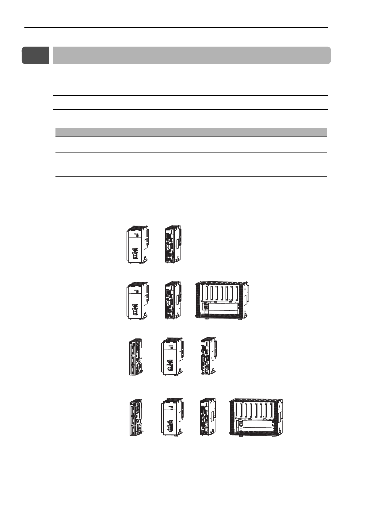
”MP3200” is a collective term that refers to the four Units in the following table.
Unit Name Primary Function
Power Supply Unit
CPU Unit
Base Unit Used to mount Optional Modules.
Rack Expansion Interface Unit Used to expand a Rack.
MP3200 Connection Example
The MP3200 is typically connected as shown in the following examples.
Supplies the power that is needed for the operation of the Units that are connected
to each other and to any Optional Modules that are connected in the Controller.
Stores the module definitions and programs, and interprets the programs. The
CPU Unit also controls the Optional Modules.
1-2
Page 21
1.1 Definition of Terms
1
Introduction
+
++
Power
Supply Unit
CPU Unit Optional Unit Base Unit
Racks
Racks
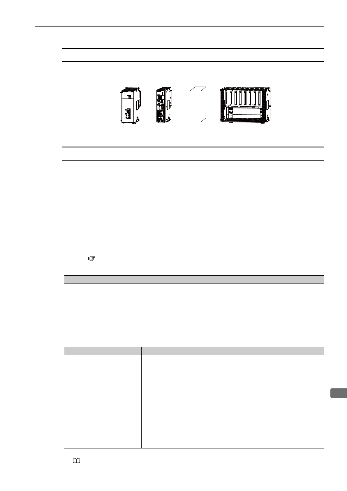
A Rack is a set of Units that are connected to each other.
Connection Example
Main Rack and Expansion Racks
You can add Units and Optional Modules to a Rack to expand functionality. However, if a restriction such
as the power supply capacity or number of Base Unit slots for one Rack is exceeded, you must add an
Expansion Rack.
You can achieve the following things by adding Units or Optional Modules to a Rack.
• Increase the number of Optional Modules that you can use.
• Increase the number of axes that are controlled.
• Use more than one CPU Unit to increase the speed of system response.
* You can not only add Expansion Racks, but you can also achieve more things by expanding the system.
Refer to the following section for details on Sub CPU synchronization and slave CPU synchronization.
If you add Racks, the Racks are classified into the Main Rack and Expansion Racks.
Type Description
Main Rack
Expansion
Racks
The method for adding Expansion Racks depends on the number of CPU Units that you use.
Number of CPU Units in Use Method to Add Expansion Racks
One CPU Unit
Two CPU Units
Three or more CPU Units
*1. Refer to the following manual for details on the MP2200 Base Unit and EXIOIF Module.
MP2200 Series User’s Manual (Manual No.: SIEP C880700 14)
*
• If you add an Expansion Rack, you can use Sub CPU synchronization under a Main CPU Unit.
• If you expand the system, you can use slave CPU synchronization with the CPU Units.
3.3 Multi-CPU Functions (page 3-94)
The Main Rack contains the Main CPU Unit.
There can be only one Main Rack in any one system configuration.
Expansion Racks are connected to the Main Rack.
You can connect up to six Expansion Racks to the Main Rack. (You can connect up to three
Expansion Racks by using a Rack Expansion Interface Unit and up to three Expansion Racks by
using EXIOIF Modules.)
Use MP2200 Base Units and EXIOIF Modules (MP2000-series Optional Mod-
ules) to add Expansion Racks.
Use one of the following methods.
• Method 1
Expand the Main Rack by connecting two CPU Units to it.
• Method 2
Use a Rack Expansion Interface Unit to add Expansion Racks.
Use the following method 1 and method 2 together, or use only method 2.
• Method 1
Expand the Main Rack by connecting two CPU Units to it.
• Method 2
Use a Rack Expansion Interface Unit to add Expansion Racks.
*1
*2
*2
1-3
Page 22

1.1 Definition of Terms
Main Rack and Expansion Racks
*2. To mount the Unit with screws, use the JEPMC-OP3006-E or JEPMC-OP3007-E Rack Reinforcement Bracket.
Refer to the following section for an expansion example.
MP3200 Expansion Example (page 1-5)
1-4
Page 23
1
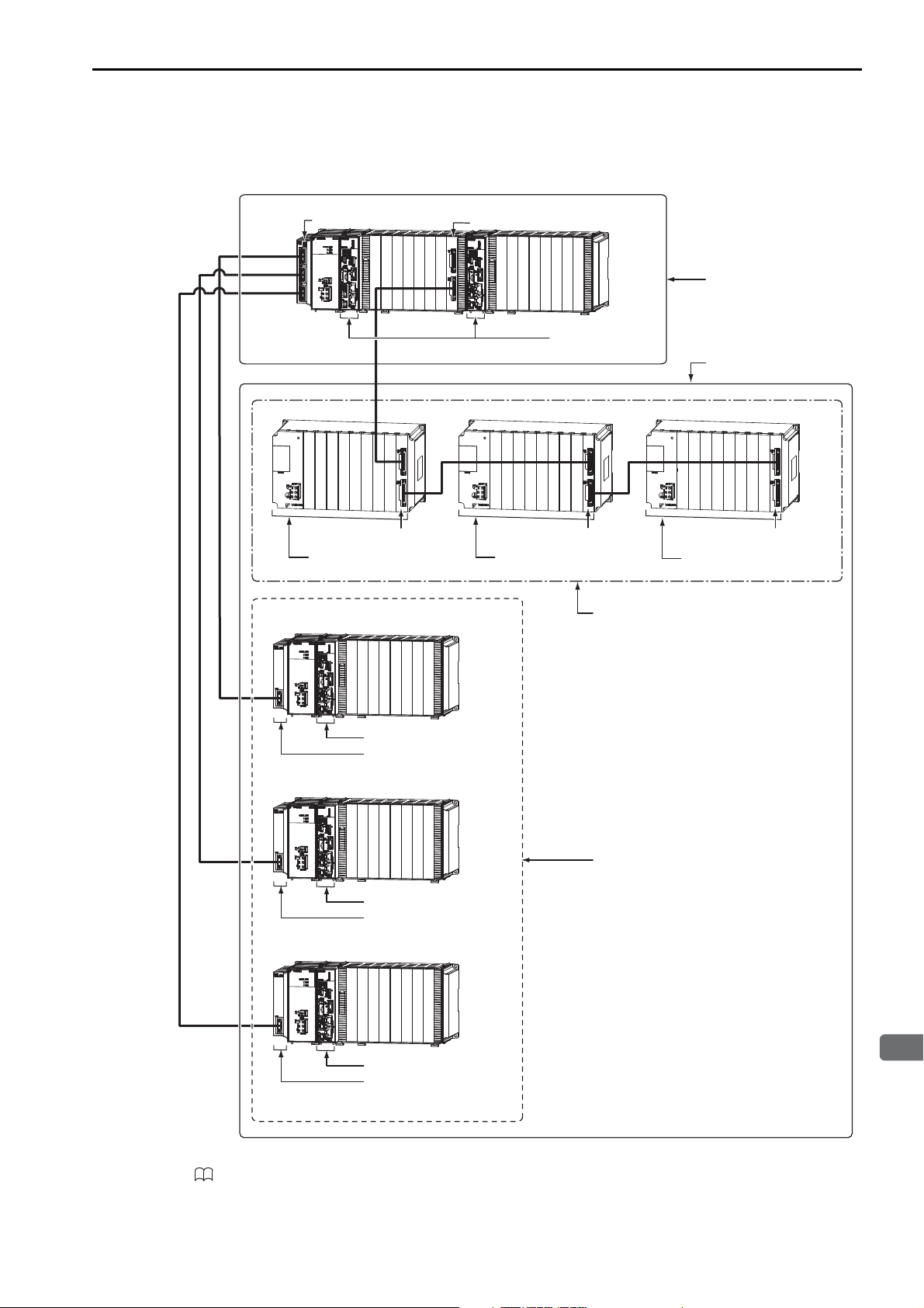
Introduction
MP3200 Expansion Example
An MP3200 expansion example is given in the following figure.
1.1 Definition of Terms
Main Rack and Expansion Racks
Rack Expansion
Interface Unit
MP2200
MBU-02
P
O
W
ER
DC
EXIOIF Module
MP2200 Base Unit
EXIOIF Module
EXIOIF
*1
CPU Unit
Main Rack
*2
Expansion Racks
(up to 6 Racks)
MP2200
EXIOIF
MBU-02
P
O
W
ER
DC
EXIOIF
EXIOIF Module
*1
MP2200 Base Unit
*1
MP2200
MBU-02
P
O
W
ER
DC
EXIOIF Module
MP2200 Base Unit
EXIOIF
*1
Expansion Racks added by using
EXIOIF Modules (up to 3 Racks)
CPU Unit
Rack Expansion
Interface Unit
Expansion Racks added by using a Rack
Expansion Interface Unit (up to 3 Racks)
CPU Unit
Rack Expansion
Interface Unit
CPU Unit
Rack Expansion
Interface Unit
*1. Refer to the following manual for details on the MP2200 Base Unit and EXIOIF Module.
MP2200 Series User’s Manual (Manual No.: SIEP C880700 14)
*2. If you use two CPU Units, you can connect to the Main Rack without adding an Expansion Rack. To mount the CPU
Units with screws, use the JEPMC-OP3006-E or JEPMC-OP3007-E Rack Reinforcement Bracket.
1-5
Page 24
1.1 Definition of Terms
Information
Rack 1 Racks 2 and 3 Rack 5
Rack number of Expansion Racks added by using the Rack Expansion Interface Unit
Rack numbers of Expansion Racks added by using EXIOIF Modules
Rack number of Main Rack
Rack Numbers
Rack Numbers
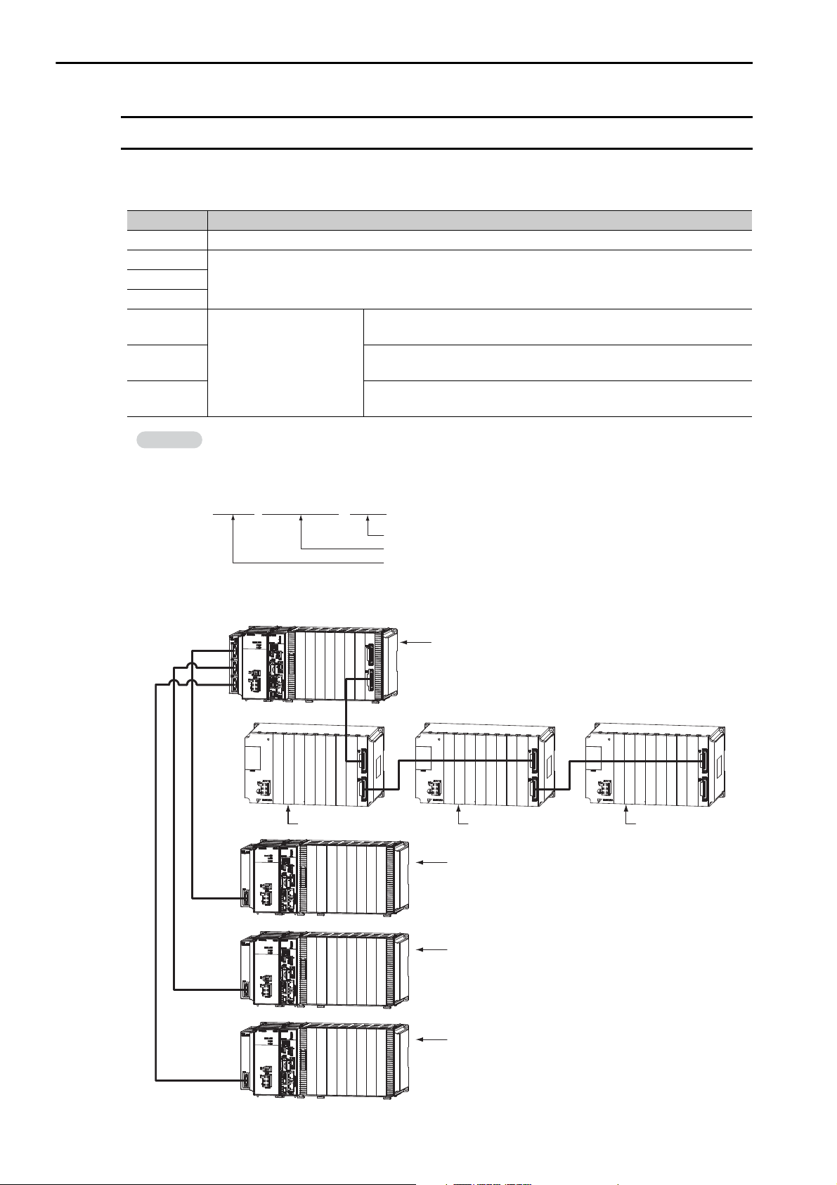
When you add Expansion Racks, the MPE720 automatically assigns a number to each Rack so that the
Racks can be identified.
Rack No. Description
Rack 1 Main Rack
Rack 2
Rack 4
Rack 5
Rack 6
Rack 7
Expansion Racks added by using EXIOIF ModulesRack 3
The Expansion Rack that is connected to port 1 on the Rack Expansion
Interface Unit on the Main Rack
Expansion Racks added by
using a Rack Expansion
Interface Unit
The Expansion Rack that is connected to port 2 on the Rack Expansion
Interface Unit on the Main Rack
The Expansion Rack that is connected to port 3 on the Rack Expansion
Interface Unit on the Main Rack
Depending on how the Expansion Racks are connected, the Rack numbers may not be sequential.
Example: If two Expansion Rack were connected with EXIOIF Modules and one Expansion Rack
was connected with a Rack Expansion Interface Unit, the Rack numbers would be as shown below.
There would be no rack 4.
The following figure illustrates Rack numbers.
EXIOIF
MP2200
M
BU-02
PO
WER
DC
Rack 2 Rack 3 Rack 4
EXIOIF
Rack 1
MP2200
M
PO
WER
DC
BU-02
Rack 5
Rack 6
MP2200
M
EXIOIF
BU-02
PO
WER
DC
EXIOIF
Rack 7
1-6
Page 25

1.1 Definition of Terms
1
Introduction
Unit Numbers
Unit Numbers
The MPE720 automatically assigns Unit numbers to the Units on each Rack so that the Units can be identified.
Numbers 1 to 5 are assigned to the Units in order from the left.
Slot Numbers
The MPE720 automatically assigns slot numbers to the slots on the Base Unit so that the slots can be identified.
Numbers 1 to 9* are assigned to the slots in order from the left.
* The highest slot number depends on the specifications of the Base Unit.
1-7
Page 26
1.2 System Configuration Example
MP2200
MBU-02
PO
W
ER
DC
EXIOIF
MP2200
MBU-02
PO
W
ER
DC
EXIOIF
PC
Ethernet
Ethernet communications cables
Ethernet
266IF-02
217IF-01
218IF-01
218IF-02
260IF-01
261IF-01
263IF-01
264IF-01
265IF-01
266IF-01
SVA-01
SVB-01
PO-01
SVC-01
MPU-01
Motion Modules
EXIOIF
Expansion Rack Module
MPALL00-0
MPAL000-0
AFMP-01
MPANL00-0
AFMP-02-C/-CA
MPAN000-0
Other Modules
(including those from other manufacturers)
External outputs
External inputs
RS-232C
Ethernet
DeviceNet
PROFIBUS
RS422/485
215 communications
SERVOPACKs
AnyWire
A-net/A-link
CC-Link
Up to 42 stations, including I/O
(Up to 32 of the stations can be Servos.)
LIO-01
LIO-02
LIO-04
LIO-05
DO-01
LIO-06
AI-01
AO-01
CNTR-01
I/O
Servomotor
Servomotor
Servomotor
MP3200
EXIOIF Module
Cable
EXIOIF Module
Cable
MECHATROLINK-III
EXIOIF
262IF-01
215AIF-01
MPCUNET-0
*1, *2
MPE720 Integrated
Engineering Tool Version 7
Optional Modules
Communications Modules
MECHATROLINK-III Cable
SERVOPACK with
MECHATROLINK-III
Communications
I/O Module with
MECHATROLINK-
III
Communications
I/O Modules
Host PLC
24-VDC power
supply, AC power
supply, or status
monitoring device
Power supply cable
24-VDC power
supply or AC
power supply
Battery
Front cover for
unused slot
RLYOUT
connector cable
Battery
Front cover for
unused slot
Battery
Front cover for
unused slot
Power supply cable
Power supply cable
Power supply cable
24-VDC power
supply or AC
power supply
24-VDC power
supply or AC
power supply
24-VDC power
supply or AC
power supply
Battery
Front cover for
unused slot
Rack Expansion
Interface Unit
Cable
1.2
System Configuration Example
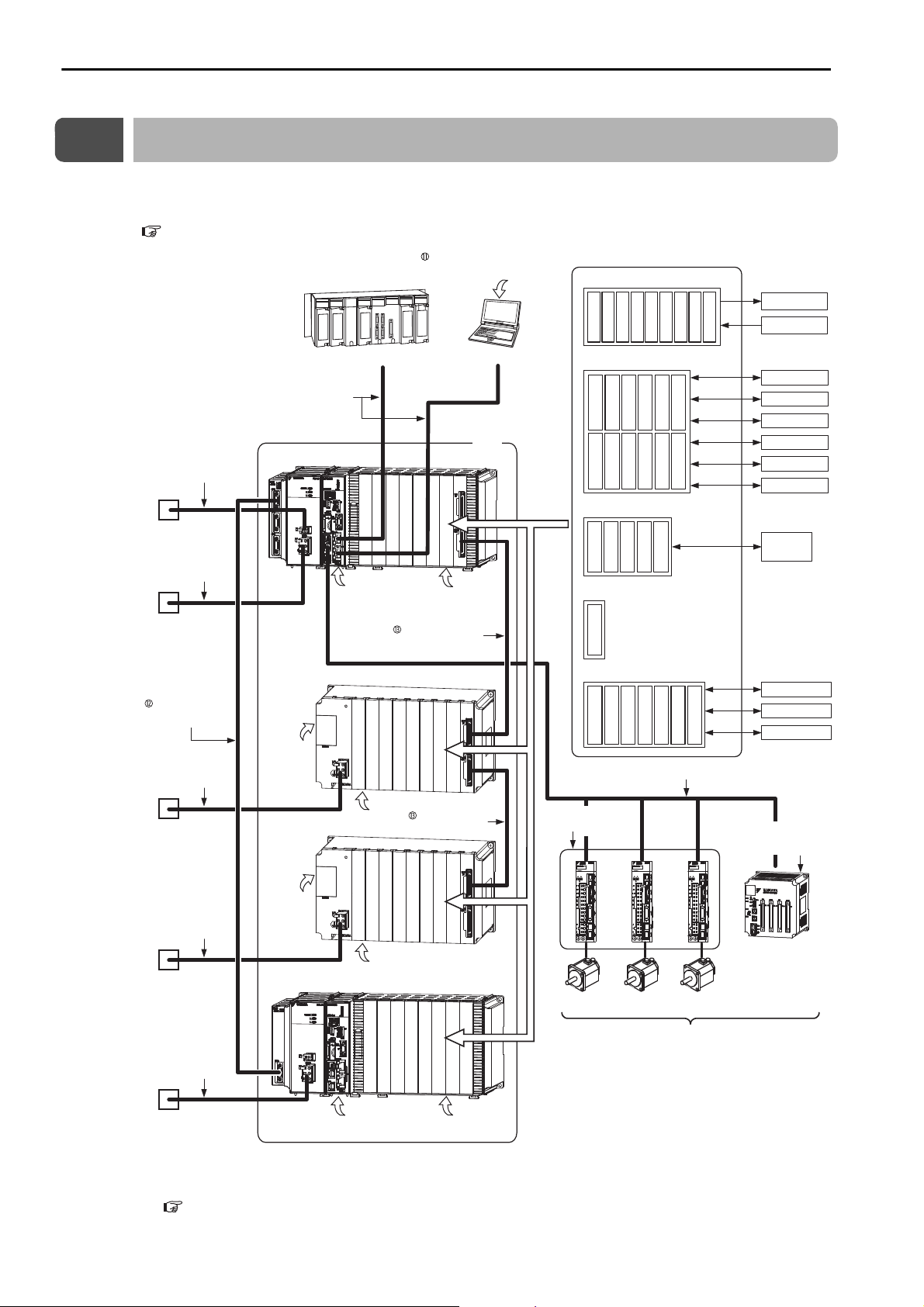
The following figure shows a typical system configuration. Refer to the following section for details on 1
to 11 in the following figure.
1.3 Devices and Components That Are Required to Build a System (page 1-9)
1-8
*1. This manual primarily describes this area.
*2. Refer to the following section for an MP3200 expansion example.
MP3200 Expansion Example (page 1-5)
Page 27
1.3 Devices and Components That Are Required to Build a System
1
Introduction
1.3
Devices and Components That Are Required to Build a System
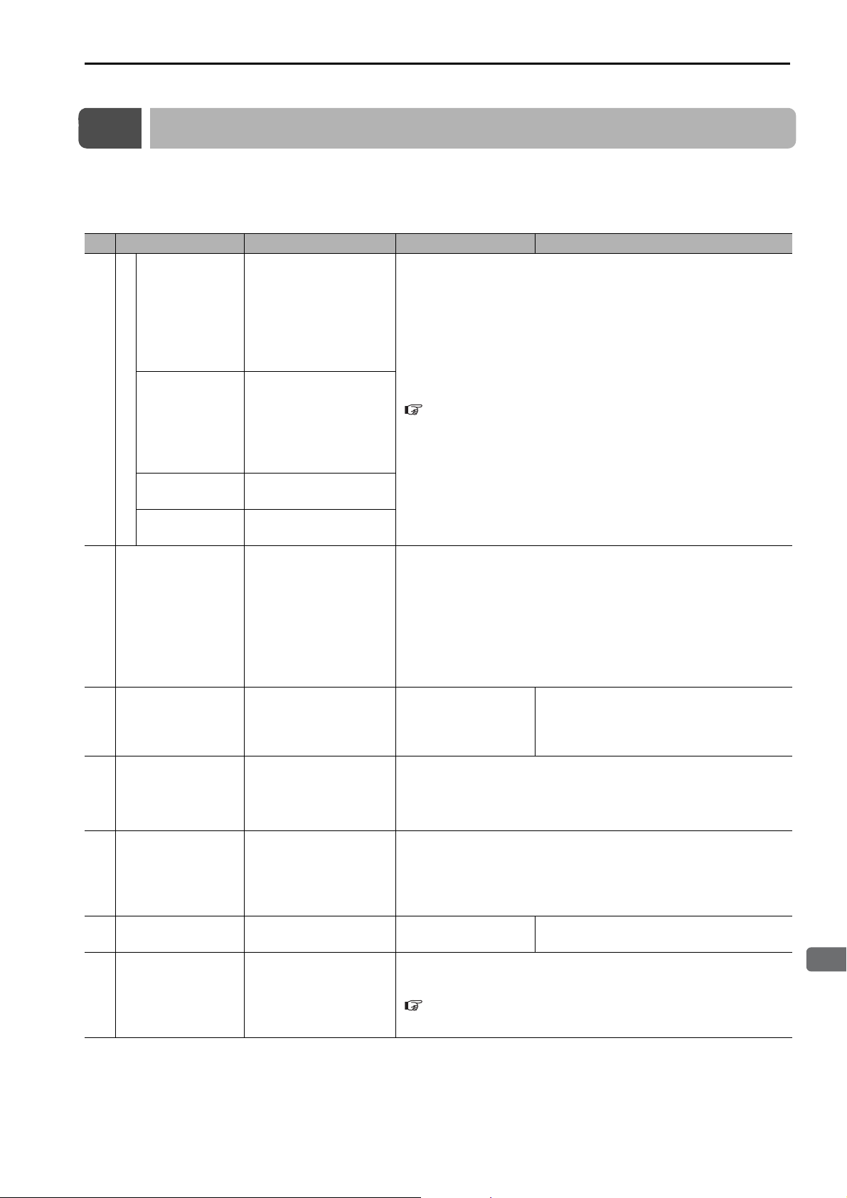
The following table lists the devices and components that are required to build the system that is shown in
1.2 System Configuration Example (page 1-8). The numbers 1 to 13 correspond to the numbers in the figure in 1.2 System Configuration Example (page 1-8).
No. Name Use Model Remarks
Supplies the power that is
needed for the operation
Power Supply
Unit
MP3200
CPU Unit
Base Unit
Rack Expansion
Interface Unit
Ethernet communica-
tions cables
Battery with Special
Connector
Power supply cable
RLYOUT connector
cable
Front cover for
unused slot
Optional Modules
of the Units that are connected to each other and
to any Optional Modules
that are connected in the
Controller.
Stores the module definitions and programs, and
interprets the programs.
The CPU Unit also controls the Optional Modules.
Used to mount Optional
Modules.
Used to expand a Rack.
Used to connect the CPU
Unit to Ethernet communications devices or to
connect the CPU Unit to
a PC that has the
MPE720 installed on it.
Provides power for the
calendar and backup
memory while the power
is turned OFF.
Connects the Power Supply Unit to a 24-VDC
power supply or an AC
power supply.
Connects the Power Supply Unit to a 24-VDC
power supply, an AC
power supply, or a status
monitoring device.
Used to cover unused
slots on the Base Unit.
Motion Modules, I/O
Modules, and Communications Modules are
selected based on the
application.
Refer to the following section for details.
MP3200 Unit List (page 1-11)
Use a commercially available cable that meets the following conditions:
• Ethernet specification: 100Base-TX
• Category 5 or higher
• Twisted-pair cable with RJ-45 connectors
Use a cross cable that meets the above conditions to connect the Main
CPU Unit to a Sub CPU Unit or to connect two Sub CPU Units.
JEPMC-OP3005 The Battery is provided with the CPU Unit.
Use a commercially available cable that meets the following conditions:
• Wire size: AWG18 to AWG13 (0.8 to 2.6 mm
• Twisted-pair cable
Use a commercially available cable that meets the following conditions:
• Wire size: AWG28 to AWG14 (0.08 to 2.0 mm
JEPMC-OP2300 −
Refer to the following section for details.
Optional Modules (page 1-12)
2
)
2
)
Continued on next page.
1-9
Page 28

1.3 Devices and Components That Are Required to Build a System
11
12
13
Continued from previous page.
No. Name Use Model Remarks
Standard cable
Length: 0.2 to 50 m
Cable with ferrite cores
Length: 10 to 50 m
Cable with loose wires at one end
Length: 0.5 to 50 m
Σ-V-series AC SERVOPACK with MECHATROLINK-III Communications for Rotational Motor
Σ-V-series AC SERVOPACK with MECHATROLINK-III Communications for Linear
Motor
MECHATROLINK-
III Cable
SERVOPACK with
MECHATROLINK-
III Communications
Connects the CPU Unit
to MECHATROLINK-III
Communications devices.
Used to control Servomotors.
JEPMC-W6012-E
JEPMC-W6013-E
JEPMC-W6014-E
SGDV-
21
SGDV-
25
64-point I/O
Module
Analog Input
Module
Analog Output
Module
Pulse Train Input
Module
I/O Modules with MECHATROLINK-III Communications
Pulse Train Output Module
MPE720 Integrated
Engineering Tool
Ver sio n 7
Rack Expansion
Interface Unit Cable
EXIOIF Module
Cable*
Used to input or output
digital, analog, or pulse
train signals.
Used to adjust, maintain,
and program AC Servo
Drives and Inverters that
are connected to the network.
Used to use a Rack
Expansion Interface Unit
to connect the Main Rack
to an Expansion Rack.
Used to use an EXIOIF
Module to connect the
Main Rack to an Expansion Rack or to connect
two Expansion Racks.
JEPMC-MTD2310-E 24 VDC, 64 inputs, 64 outputs
JEPMC-MTA2900-E 8 analog input channels
JEPMC-MTA2910-E 4 analog output channels
JEPMC-MTP2900-E 2 pulse-train inputs
JEPMC-MTP2910-E 4 pulse-train outputs
CPMC-MPE780 −
JEPMC-W3401-A5-E Length: 0.5 m
JEPMC-W3401-2A5-E Length: 2.5 m
JEPMC-W3401-06-E Length: 6.0 m
JEPMC-W2094-A5-E Length: 0.5 m
• Connector on both ends
with ferrite cores
• Wire size: AWG28
• Twin coaxial cable
• If you use more than one
Cable, do not allow the
total cable length to
JEPMC-W2094-01-E Length: 1.0 m
exceed 6 m.
• Connector on both ends
with ferrite cores
JEPMC-W2094-2A5-E Length: 2.5 m
• Wire size: AWG28
• Equivalent to UL20276.
Continued on next page.
1-10
Page 29
1.3 Devices and Components That Are Required to Build a System
1
Introduction
Continued from previous page.
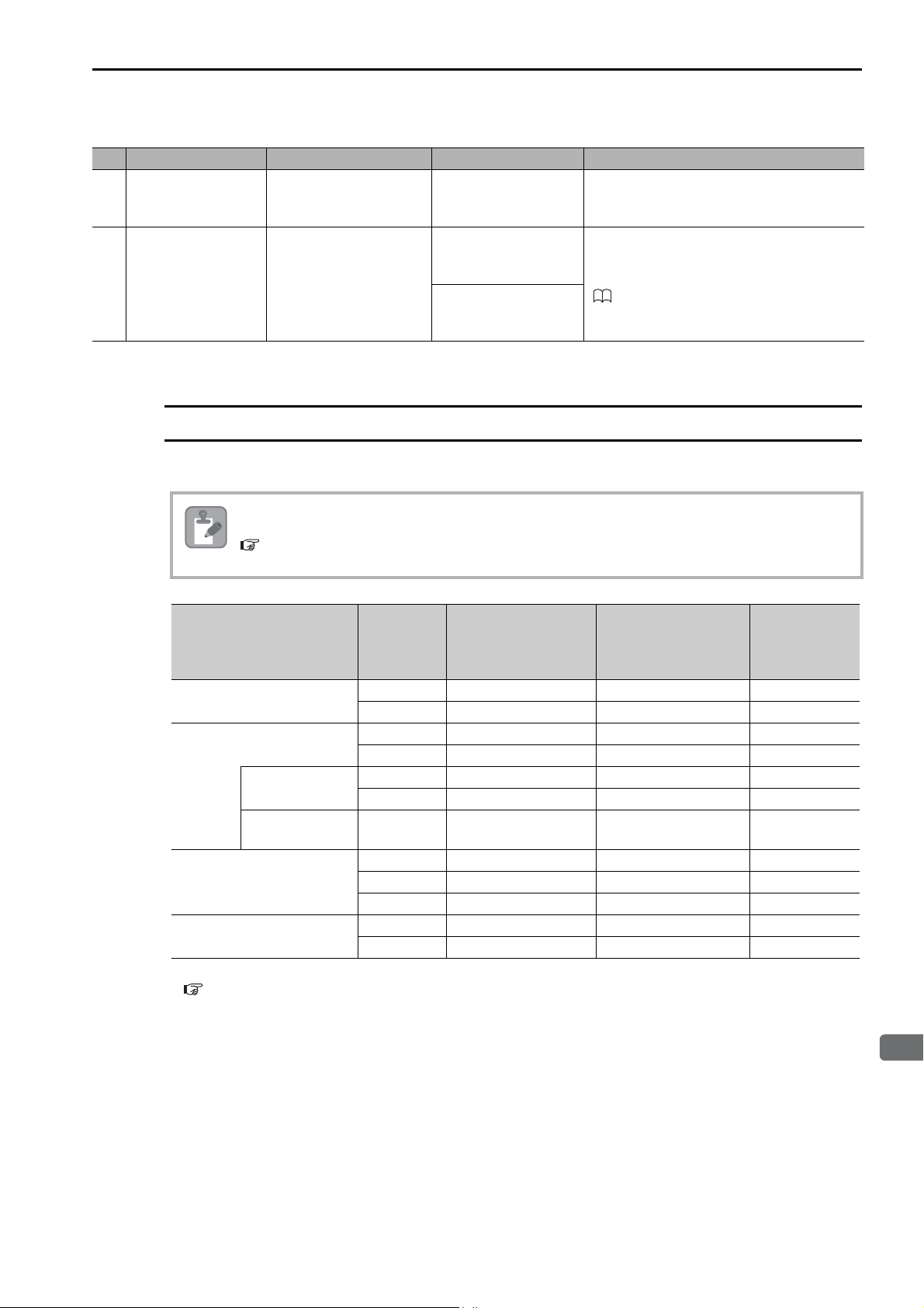
No. Name Use Model Remarks
Panel-mounting
−
Bracket
Rack Reinforcement
−
Bracket
* You cannot use an MP2000-series EXIOIF Module Cable (model: JEPMC-W2091-()).
Used to mount the
MP3200 inside a control
panel.
Used to mount the Sub
CPU Unit to the Main
Rack with screws.
JEPMC-OP3001-E
JEPMC-OP3006-E
JEPMC-OP3007-E
This Attachment is provided with the Power
Supply Unit.
Refer to the following manual for information on model selection and mounting methods.
MP2200/MP3000 Series Machine Controller
System Setup Manual (Manual No.: SIEP
C880725 00)
MP3200 Unit List
The following table lists the MP3200 Units.
MP3200 Unit List
Observe all precautions when combining MP3200 Units. Refer to the following section for details.
Note
Power Supply Units
CPU Unit
Base Units
Rack Expansion Interface
Unit
* Refer to the following section for details.
3.2 Function Modules - Motion Control Function Modules (SVC32 and SVR32) (page 3-50)
Precautions When Combining MP3200 Units (page 1-14)
Unit
Motion Control
Function Module
Communications
Function Module
Abbrevia-
tion
PSA-12 JEPMC-PSA3012-E AC power supply −
PSD-12 JEPMC-PSD3012-E DC power supply −
CPU-201 JEPMC-CP3201-E − 2,000 mA
CPU-202 JEPMC-CP3202-E − 4,000 mA
SVC32 − MECHATROLINK -III −
SVR32 − Virtual axes* −
218IFD − Ethernet −
MBU-B03 JEPMC-BUB3003-E 3 slots 10 mA
MBU-B05 JEPMC-BUB3005-E 5 slots 10 mA
MBU-B08 JEPMC-BUB3008-E 8 slots 10 mA
EXU-001 JEPMC-EXU3001-E For Main Rack 1,500 mA
EXU-002 JEPMC-EXU3002-E For Expansion Rack 1,500 mA
Model Description
Maximum
Internal
Current
Consumption
1-11
Page 30
1.3 Devices and Components That Are Required to Build a System
Optional Modules
Optional Modules
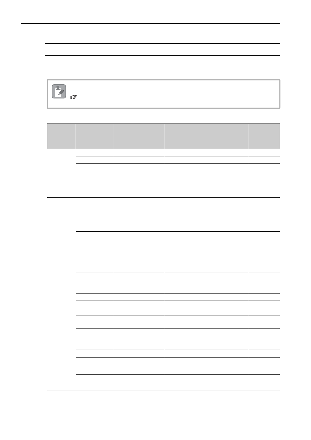
You can add the Optional Modules that are listed in the following table for as many open slots there are in
the Base Unit.
Observe all precautions when combining Optional Modules. Refer to the following section for details.
Note
Unit Abbreviation Model Description
Motion
Modules
Communications
Modules
* Refer to the manuals for individual Optional Modules for details.
Precautions When Combining Optional Modules (page 1-14)
SVC-01 JAPMC-MC2320-E MECHATROLINK -III × 1 460 mA
SVB-01 JAPMC-MC2310-E MECHATROLINK -II × 1 470 mA
SVA-01 JAPMC-MC2300 2-axis analog servo interface 540 mA
PO-01 JAPMC-PL2310-E 4-axis control with pulse-train output 760 mA
MPU-01 JAPMC-CP2700-E
217IF-01 JAPMC-CM2310-E RS-232C/RS-422 communications 240 mA
218IF-01
218IF-02
JAPMC-CM2300-E
JAPMC-CM2302-E
260IF-01 JAPMC-CM2320-E RS-232C/DeviceNet communications 150 mA
261IF-01
262IF-01
263IF-01
264IF-01
JAPMC-CM2330-E RS-232C/PROFIBUS communications 260 mA
JAPMC-CM2303-E FL-net communications 480 mA
JAPMC-CM2304-E EtherNet/IP communications 480 mA
JAPMC-CM2305-E EtherCAT (EtherCAT slave) 540 mA
265IF-01 JAPMC-CM2390-E
266IF-01 JAPMC-CM2306-E PROFINET master 540 mA
266IF-02 JAPMC-CM2307-E PROFINET slave 540 mA
215AIF-01
JAPMC-CM2360-E RS-232C/MPLINK communications 410 mA
JAPMC-CM2361 RS-232C/CP-215 communications 420 mA
AFMP-01 −
AFMP-02-C − CC-Link by Anywire Corporation
AFMP-02-CA −
MPANL00-0
MPALL00-0
MPAL000-0
MPAN000-0
− A-net/A-Link by ALGO System
− A-Link/A-Link by ALGO System
− A-Link by ALGO System
− A-net by ALGO System
MPCUNET-0 − CUnet by ALGO System
Optional Module with CPU Unit and
SVC-01 functionality
MECHATROLINK -III × 1
RS-232C/Ethernet communications
(10Base-T)
RS-232C/Ethernet communications
(100Base-TX/10Base-T)
CompoNet (I/O communications and
message communications)
Anywire-Master DB by Anywire Corporation
CC-Link and Anywire-Master DB by
Anywire Corporation
Continued on next page.
Maximum
Internal
Current
Consumption
580 mA
360 mA
480 mA
200 mA
*
*
*
*
*
*
*
*
1-12
Page 31
1.3 Devices and Components That Are Required to Build a System
1
Introduction
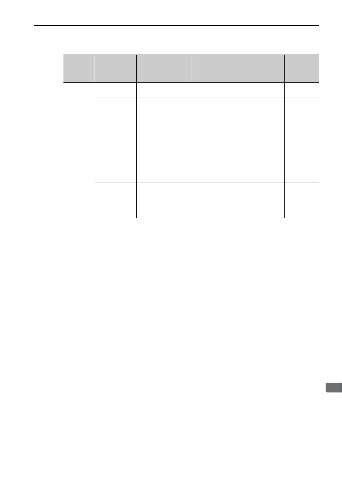
Unit Abbreviation Model Description
16 inputs, 16 sinking outputs, 1 pulsetrain input
16 inputs, 16 sourcing outputs, 1 pulsetrain input
8 digital inputs, 8 digital sinking outputs
1 analog input channel and 1 analog
output channel
1 pulse-train counter channel
2 counter channels, input circuits: 5 V
or 12 V
I/O
Modules
Expansion
Rack Module
LIO-01 JAPMC-IO2300-E
LIO-02 JAPMC-IO2301-E
LIO-04 JAPMC-IO2303-E 32 inputs, 32 sinking outputs 400 mA
LIO-05 JAPMC-IO2304-E 32 inputs, 32 sourcing outputs 400 mA
LIO-06 JAPMC-IO2305-E
DO-01
AI-01 JAPMC-AN2300-E 8 analog input channels 340 mA
AO-01 JAPMC-AN2310-E 4 analog output channels 740 mA
CNTR-01
EXIOIF JAPMC-EX2200-E −−
JAPMC-DO2300-E 64 sinking outputs 500 mA
JAPMC-PL2300-E
Optional Modules
Continued from previous page.
Maximum
Internal
Current
Consumption
300 mA
300 mA
500 mA
610 mA
1-13
Page 32
1.4 Precautions When Combining Products
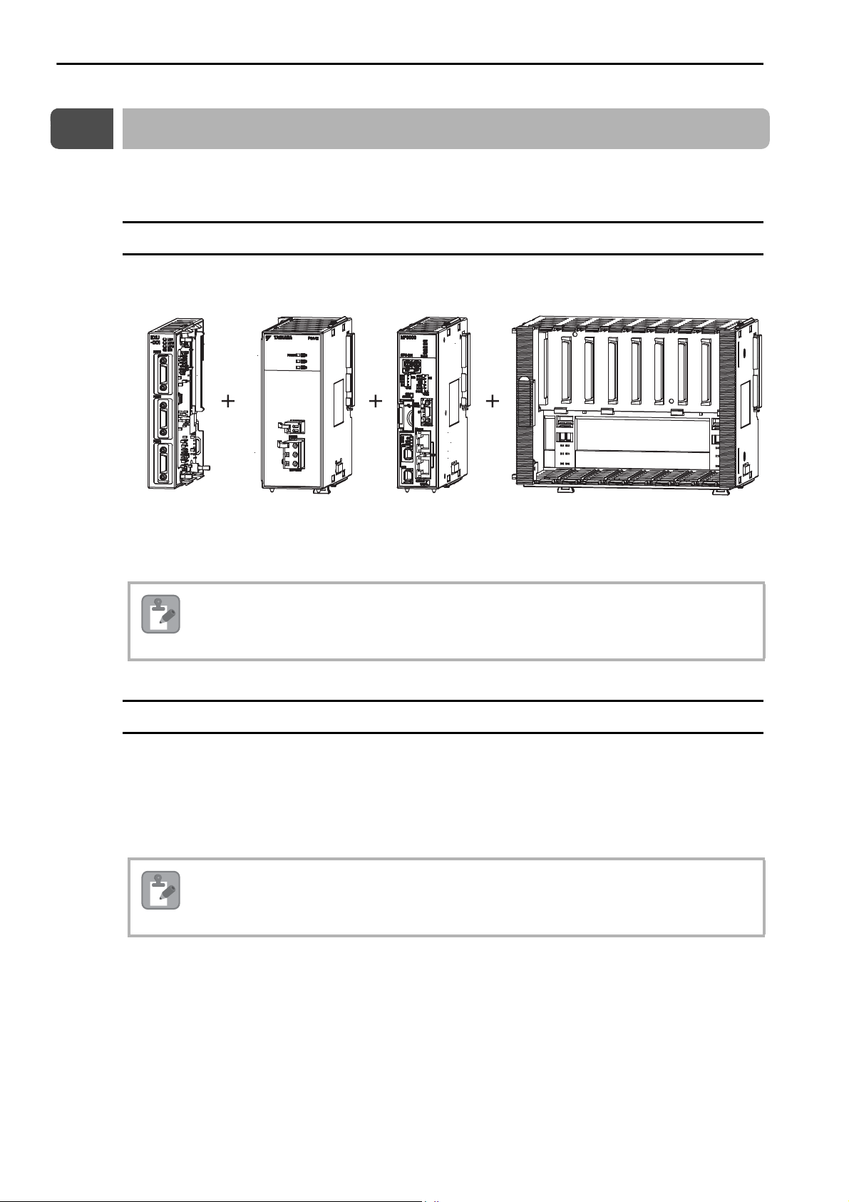
Power Supply Unit CPU Unit Base Unit
Rack Expansion
Interface Unit
(for Main Rack or
Expansion Rack)
Precautions When Combining MP3200 Units
1.4
Precautions When Combining Products
The following precautions must be observed when combining the MP3200 Units and Optional Modules.
Precautions When Combining MP3200 Units
There are restrictions in the order in which you can connect the Units. Build the Rack by connecting each
Unit in the order that is shown below.
The Units will not operate if they are connected in the wrong order (e.g., if the Base Unit is connected
to the left side of the Power Supply Unit).
Note
Precautions When Combining Optional Modules
When combining Optional Modules, make sure the following conditions are met.
*
• The output current of the Power Supply Unit
or less of the rated current capacity.
* This is the total of the maximum internal current consumption of the Base Units and Optional Modules that are con-
nected to the Power Supply Unit.
Always attach the front covers to unused slots on the Base Unit.
Note
must be held to approximately 75% (approximately 9 A)
1-14
Page 33

1.5 Precautions When Setting the Parameters
1
Introduction
Precautions When Setting the Circuit Numbers
1.5
Precautions When Setting the Parameters
Observe the following precautions when setting the MP3200.
Precautions When Setting the Circuit Numbers
When assigning circuit numbers to the Motion Control and Communications Function Modules, the numbers must be within the following ranges.
Circuit
numbers
1 to 16
1 to 8
Function Modules in
CPU Unit
Optional Modules
Unit Abbreviations of Built-in Modules
Motion Control
Function Module
Communications
Function Module
Motion Modules
Communications
Modules
SVC32, SVR32 1 to 16
218IFD 1 to 8
SVA-01 (SVA), SVB-01 (SVB01),
SVC-01 (SVC), MPU-01 (MPUIF),
PO-01 (PO)
217IF-01 (217IF) 1 to 16
218IF-01 (218IF), 218IF-02 (218IFB),
260IF-01 (260IF (DeviceNet)),
261IF-01 (261IFS (Profibus)),
262IF-01 (FL-net),
263IF-01 (EtherNet/IP),
264IF-01 (EtherCAT-S),
265IF-01 (Componet),
266IF-01, 266IF-02,
215AIF-01 (MPLINK),
215AIF-01 (CP-215)
Precautions When Setting Module Configuration Definitions
Observe the following precautions when writing module configuration definitions.
• Write the module configuration definitions only when the high-speed scan has sufficient unused processing time.
Otherwise, processing may exceed the time limit of the high-speed scan.
• Before writing module configuration definitions, make sure the machine is not in operation.
• Before you use the Machine Controller, save any written data to flash memory and turn the power supply to the Racks OFF and ON again.
1-15
Page 34

Appearances and Parts
This section describes the appearance and parts of the MP3200.
2
2.1
2.2
2.3
2.4
Power Supply Units . . . . . . . . . . . . . . . . . . . . . . . 2-2
Appearance and Part Names . . . . . . . . . . . . . . . . . . . . . . . . . 2-2
Indicators . . . . . . . . . . . . . . . . . . . . . . . . . . . . . . . . . . . . . . . . 2-2
Connectors . . . . . . . . . . . . . . . . . . . . . . . . . . . . . . . . . . . . . . . 2-3
CPU Unit . . . . . . . . . . . . . . . . . . . . . . . . . . . . . . . 2-5
Appearance and Part Names . . . . . . . . . . . . . . . . . . . . . . . . . 2-5
Display and Indicators . . . . . . . . . . . . . . . . . . . . . . . . . . . . . . 2-6
Switches . . . . . . . . . . . . . . . . . . . . . . . . . . . . . . . . . . . . . . . . . 2-9
Connectors . . . . . . . . . . . . . . . . . . . . . . . . . . . . . . . . . . . . . . 2-11
Fan . . . . . . . . . . . . . . . . . . . . . . . . . . . . . . . . . . . . . . . . . . . . 2-12
Temperature Sensor . . . . . . . . . . . . . . . . . . . . . . . . . . . . . . . 2-13
Base Units . . . . . . . . . . . . . . . . . . . . . . . . . . . . . 2-14
Appearance and Part Names . . . . . . . . . . . . . . . . . . . . . . . . 2-14
Connector . . . . . . . . . . . . . . . . . . . . . . . . . . . . . . . . . . . . . . . 2-14
Rack Expansion Interface Unit . . . . . . . . . . . . . . 2-15
Appearance and Part Names . . . . . . . . . . . . . . . . . . . . . . . . 2-15
Indicators . . . . . . . . . . . . . . . . . . . . . . . . . . . . . . . . . . . . . . . 2-16
Connectors . . . . . . . . . . . . . . . . . . . . . . . . . . . . . . . . . . . . . . 2-17
Page 35
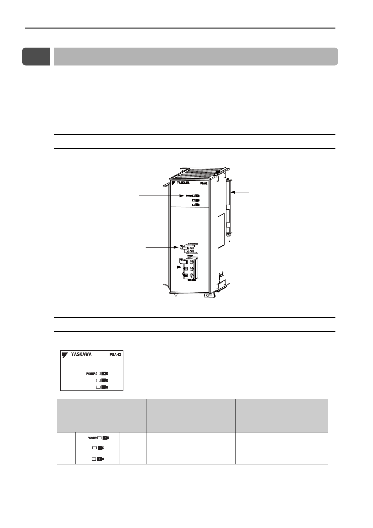
2.1 Power Supply Units
Indicators
RLYOUT connector
Power connector
Unit connector
Appearance and Part Names
2.1
Power Supply Units
The Power Supply Unit supplies the connected Units and Optional Modules with the power needed to
operate. There are two Power Supply Units available: an AC Power Supply Unit and a DC Power Supply
Unit.
This section shows the appearance and part names of the Power Supply Unit and describes the indicators
and connectors.
Appearance and Part Names
The following figure shows the appearance of the Power Supply Unit and the part names.
Indicators
These indicators show the load on the Power Supply Unit.
Output Current 8.9 A or less 9.0 to 11.4 A
Load
Green
Indi-
cator
Note: : Lit, : Not lit.
* Reduce the number of Optional Modules that are connected.
Yellow
Red
Normal: Within power supply
capacity
11.5 to 13.9 A*14.0 A or more
Normal: Maxi-
mum power
supply capacity
Error: Over
power supply
capacity
*
2-2
Page 36
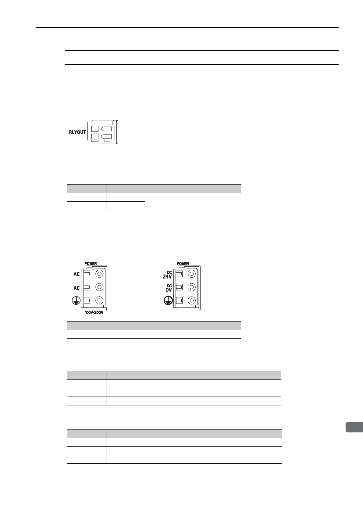
2.1 Power Supply Units
2
Appearances and Parts
DC Power Supply UnitAC Power Supply Unit
Connectors
The Power Supply Unit has three connectors: RLYOUT, power supply, and Unit connectors.
RLYOUT Connector
This connector outputs the operating status of the CPU Unit.
Model: 734-302
Pin Assignments
No. Signal Label Description
1OUT
2OUT
• Normal operation: Circuit closed.
• Error: Circuit open.
Connectors
Power Connector
Connect the power supply to this connector.
Type Model Color
AC Power Supply Unit 721-203/026-304 Black
DC Power Supply Unit 721-203/026-000 White
Pin Assignments: AC Power Supply Unit
Pin No. Signal Label Description
3 AC AC input
2 AC AC input
1 FG Connects to the frame ground. (Ground to 100 Ω max.)
Pin Assignments: DC Power Supply Unit
Pin No. Signal Label Description
3 24 VDC Power input wire for 24 VDC
2 0 VDC Power input wire for 0 VDC
1 FG Connects to the frame ground. (Ground to 100 Ω max.)
2-3
Page 37

2.1 Power Supply Units
Connectors
Unit Connector
This connector is used to connect the next Unit.
Refer to the following manual for details on connecting Units.
MP2000/MP3000 Series Machine Controller System Setup Manual (Manual No.: SIEP C880725 00)
2-4
Page 38
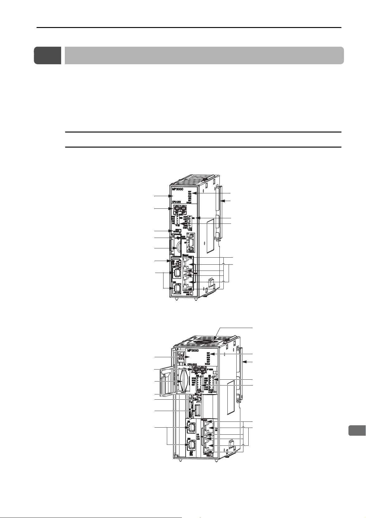
2.2 CPU Unit
2
Appearances and Parts
Display
Rotary switches
USB status indicator
STOP/SAVE switch*
USB connector*
MECHATROLINK-
III status indicators
MECHATROLINK-
III connectors
Status indicators
Unit connector
DIP switch: Mode switch 1
DIP switch: Mode switch 2
Ethernet status indicators
Ethernet connectors
Appearance and Part Names
2.2
CPU Unit
The CPU Unit stores the module definitions and programs, and interprets the programs. The CPU Unit
also controls the Optional Modules.
This section shows the appearance and part names of the CPU Unit and describes the indicators, switches,
connectors, Fan,
* These are built into the CPU-202 only.
Appearance and Part Names
The following figure shows the appearance of the CPU Unit and the part names.
CPU-201
*
and temperature sensor.
*
* Open the cover to access the switch and USB connector.
CPU-202
* Open the cover to connect or remove the Battery.
Rotary switches
USB status indicator
STOP/SAVE switch
MECHATROLINK-
Display
Battery*
USB connector
III
connectors
Fan
Status indicators
Unit connector
DIP switch: Mode switch 1
DIP switch: Mode switch 2
Ethernet status indicators
Ethernet connectors
2-5
Page 39
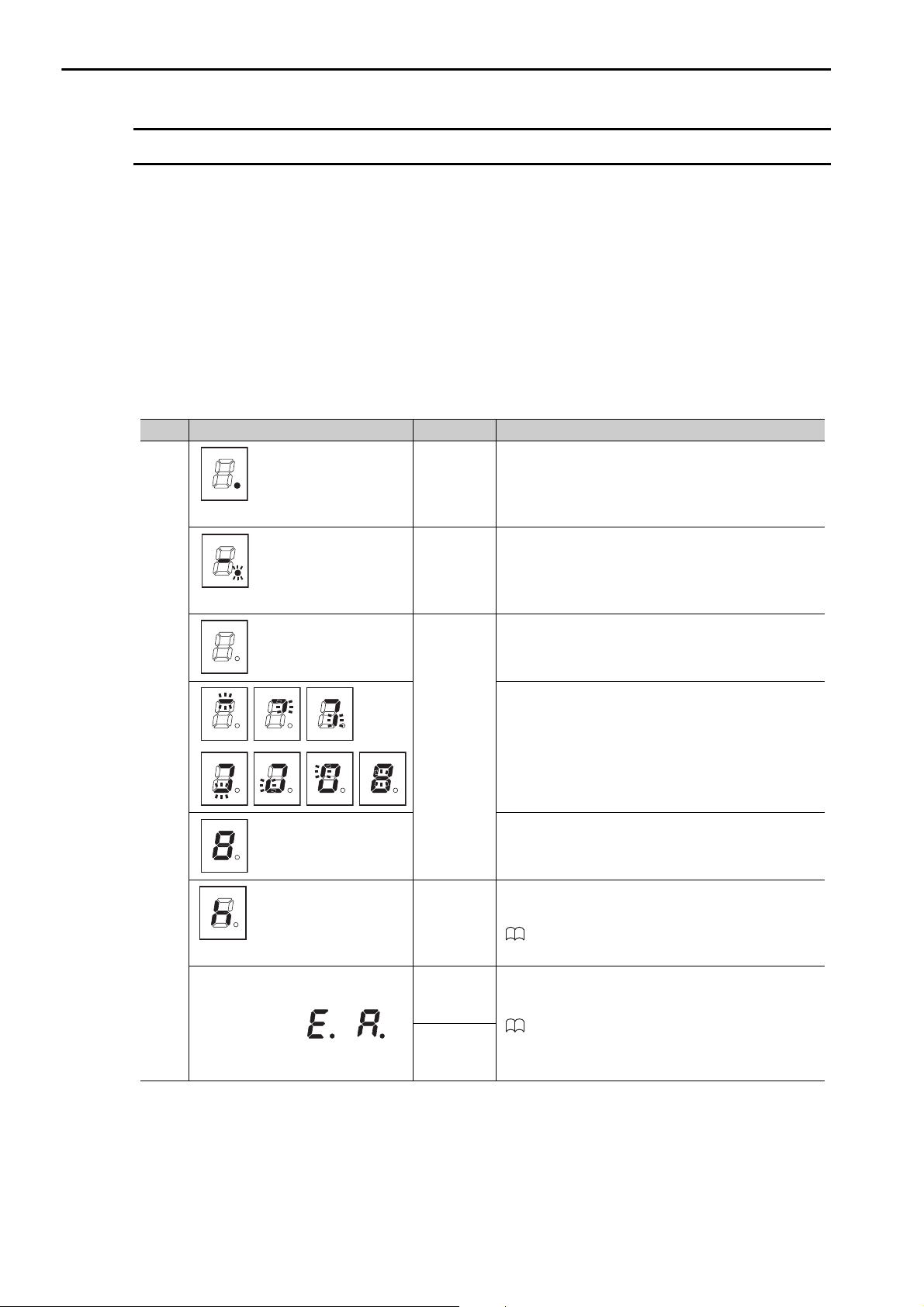
2.2 CPU Unit
Display and Indicators
Display and Indicators
The CPU Unit has the following display and four indicators.
•Display
• Status indicators
• USB status indicator
• MECHATROLINK-III status indicators
• Ethernet status indicators
Display
The display shows the execution or error status of the CPU Unit.
Color Display Status Description
Red
Lit dot at lower right
Flashing dot at lower right
(Displayed by CPU-202 only.)
Three digits after or
Initializing
Normal
operation
USB memory batch
transfer
Failsafe
function
stopped the
CPU Unit.
A system
error
occurred.
An alarm
occurred.
The CPU Unit started normally after the power was
turned ON or after the system was reset.
The CPU Unit is operating normally.
Save or load is starting.
Save or load is in progress.
Save or load was completed.
After 2 seconds, the display will indicate the status of
the CPU Unit.
Refer to the following manual for information on
internal temperature errors and Fan operation failure.
MP3000 Series MP3200 Troubleshooting Manual
(Manual No.: SIEP C880725 01)
Refer to the following manual for details on errors.
MP3000 Series Basic Units Troubleshooting Manual
(Manual No.: SIEP C880725 01)
2-6
Page 40
2
Appearances and Parts
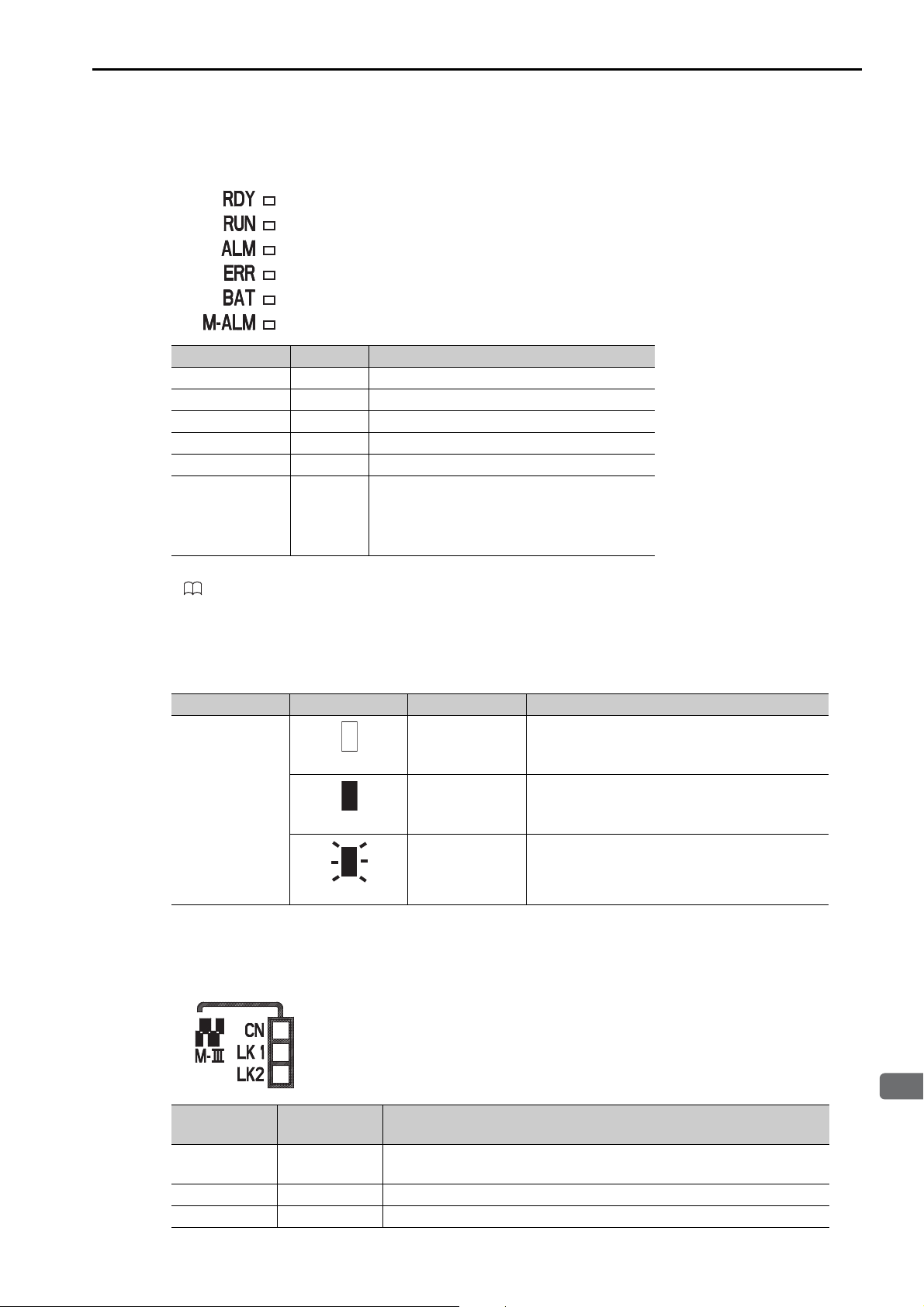
Status Indicators
These indicators show the status of the CPU Unit.
Indicator Name Color Status When Lit*
RDY Green Operation is normal.
RUN Green A user program is being executed.
ALM Red An alarm occurred.
ERR Red An error occurred.
BAT Red The battery alarm occurred.
An error occurred with one of the Servo axes:
M_ALM Red
* Refer to the following manual for details.
MP3000 Series MP3200 Troubleshooting Manual (Manual No.: SIEP C880725 01)
• Warning
•Alarm
• Command Error Completed Status
2.2 CPU Unit
Display and Indicators
USB Status Indicator
This indicator shows the status of the USB memory.
Indicator Name Indicator Status Status Description
USB
ACTIVE
Not lit
Lit
Flashing
No USB memory
device
USB memory
device inserted
Accessing USB
memory
No USB memory device has been inserted yet, or
the USB memory device is ready to be removed.
A USB memory device is inserted.
The USB memory is being accessed.
MECHATROLINK-III Status Indicators
These indicators show the status of the MECHATROLINK-III communications.
Indicator
Name
CN Green
LK1 Green MECHATROLINK-III communications are active on PORT1.
LK2 Green MECHATROLINK-III communications are active on PORT2.
Color Status When Lit
MECHATROLINK-III communications is established with the CPU Unit
as a slave (i.e., the Connect command is ON).
2-7
Page 41
2.2 CPU Unit
Display and Indicators
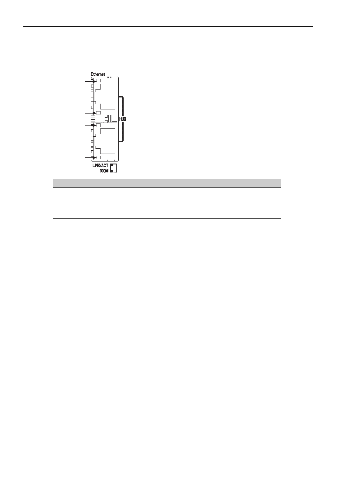
Ethernet Status Indicators
These indicators show the status of Ethernet communications.
LINK/ACT
LINK/ACT
Indicator Name Color Status When Not Lit, Lit, or Flashing
LINK/ACT Yellow
100M Green
100M
100M
Lit: Ethernet link established.
Flashing: Ethernet communications activity.
Not lit: 10 M connection
Lit: 100 M connection
2-8
Page 42
2
Appearances and Parts
Switches
The CPU Unit has the following four switches.
• DIP switch: Mode switch 1
• DIP switch: Mode switch 2
• Rotary switches
• STOP/SAVE switch
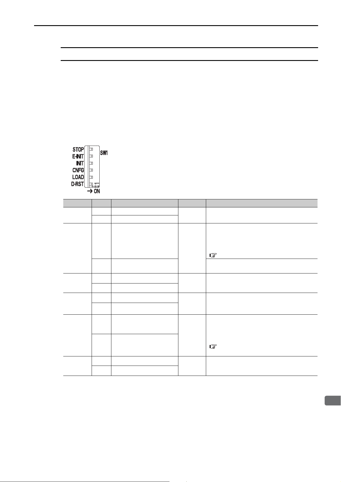
DIP Switch: Mode Switch 1
This DIP switch primarily sets the operating mode of the CPU Unit.
2.2 CPU Unit
Switches
Pin Name Status Operating Mode Default Remarks
STOP
E-INIT
INIT
CNFG
LOAD
D-RST
ON Stops the user programs.
OFF Executes the user programs.
ON
OFF
ON Resets memory.
OFF Normal operation
ON Configuration Mode
OFF Normal operation
ON Load data.
OFF Does not load data.
ON Reserved for system.
OFF Normal operation
Sets the IP address to
192.168.001..
Sets the IP address that is set
in the MPE720.
OFF
OFF
OFF
OFF
OFF
OFF Keep this pin OFF at all times.
Turn ON the pin to stop execution of the user
program.
The setting of is determined by the rotary
switch setting.
Refer to the following section for details on the
setting.
Rotary Switches (page 2-10)
−
Turn OFF the pin to execute the programs that
are stored in the flash memory.
Turn ON the pin to perform self configuration.
Turn OFF the pin to operate according to the
definitions that are stored in the flash memory.
Turn ON the pin and then turn ON the power to
batch load data from the USB memory to the
CPU Unit.
Refer to the following section for details.
3.2 Function Modules − USB Memory (page 3-
85)
2-9
Page 43
2.2 CPU Unit
···
···
···
Switches
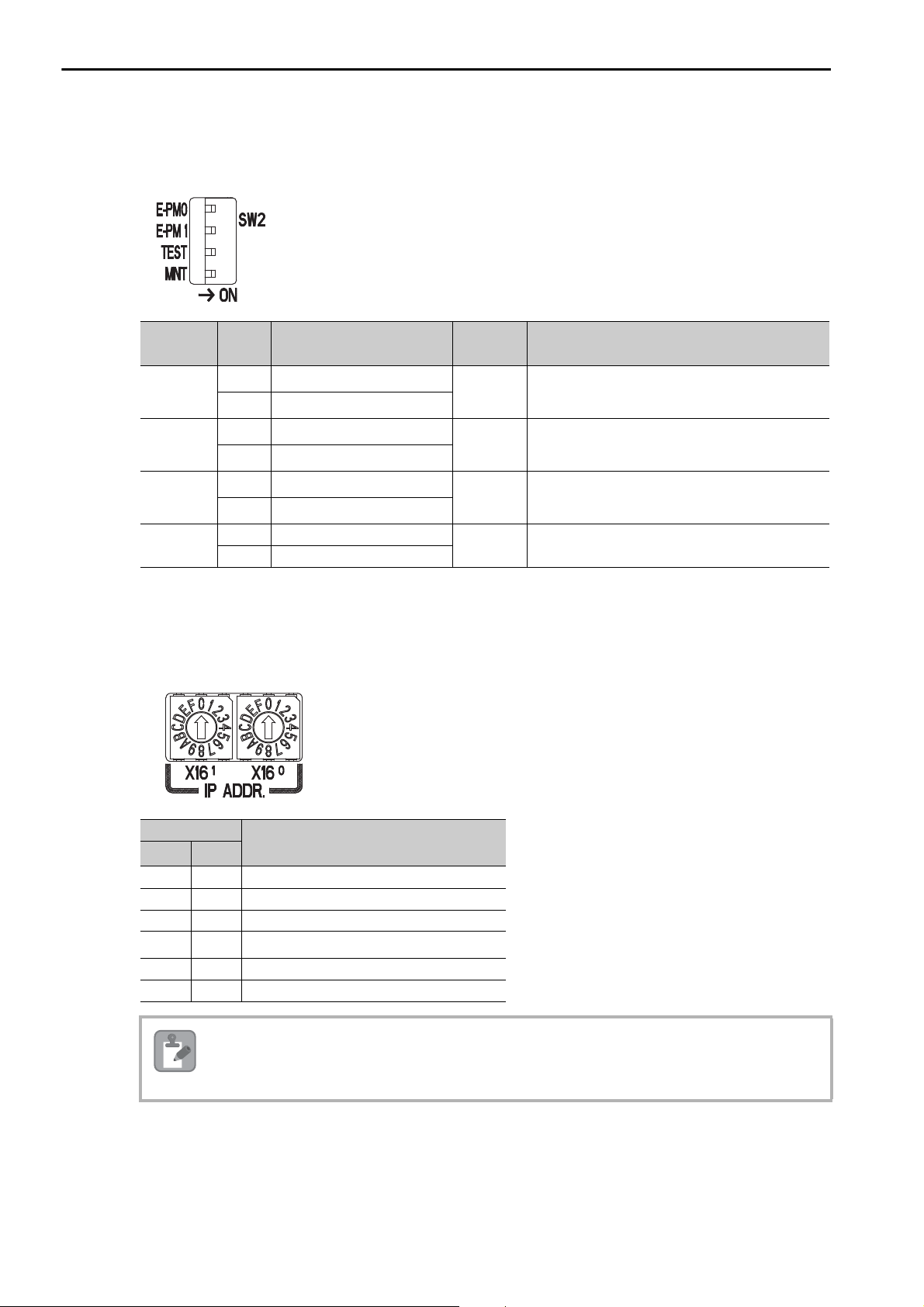
DIP Switch: Mode Switch 2
This DIP switch primarily sets the operating mode of the CPU Unit.
Pin Name Status Operating Mode Default Remarks
E-PM0
E-PM1
TEST
MNT
ON Reserved for system.
OFF Normal operation
ON Reserved for system.
OFF Normal operation
ON Reserved for system.
OFF Normal operation
ON Reserved for system.
OFF Normal operation
OFF Keep this pin OFF at all times.
OFF Keep this pin OFF at all times.
OFF Keep this pin OFF at all times.
OFF Keep this pin OFF at all times.
Rotary Switches
When the E-INIT pin on Mode Switch 1 is ON, the IP address will be set to 192.168.001.. The
value of is set on the rotary switches, S1 and S2. Set the hexadecimal value.
2-10
Set Value
X161X16
0 0 Reserved for system.
0 1 192.168.001.001 (default setting)
0 2 192.168.001.002
F E 192.168.001.254
F F Reserved for system.
Note
0
To enable the rotary switch setting, turn ON the E-INIT pin on the mode switch 1. If the E-INIT pin is
OFF, the IP address will be set from the MPE720.
IP Address
Page 44
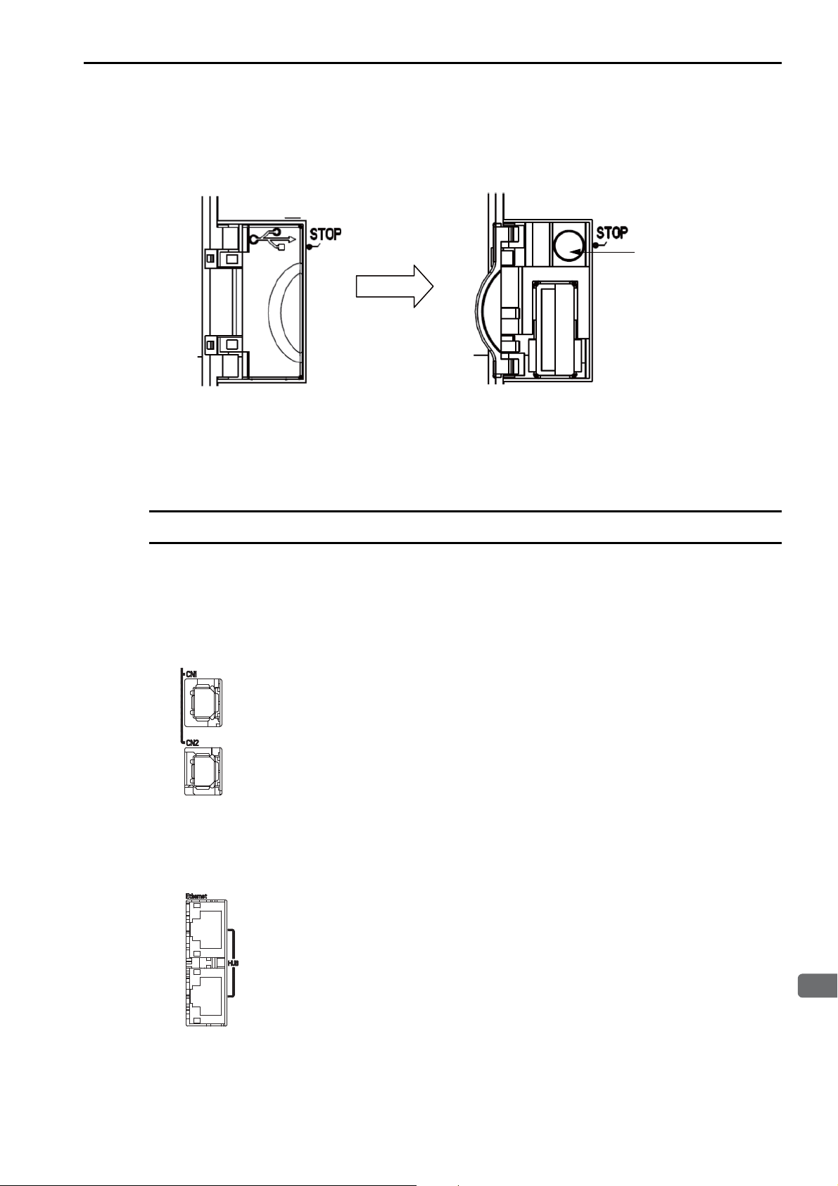
2.2 CPU Unit
2
Appearances and Parts
Open the cover.
STOP/SAVE switch
Connectors
STOP/SAVE Switch
This switch is used when removing the USB memory device, or when batch saving data to the USB memory.
• Lightly press this switch to prepare the USB memory device for removal. The USB memory device can
be safely removed when the USB status indicator changes from flashing to not lit.
• Press and hold this switch for at least 2 seconds to save all of the data to the USB memory. The display
will show the progress of saving.
Connectors
The CPU Unit has four connectors: MECHATROLINK-III, Ethernet, USB, and Unit connectors.
MECHATROLINK-III Connectors
These connectors are used to connect MECHATROLINK-III communications devices.
Ethernet Connectors
These connectors are used to connect Ethernet communications devices.
2-11
Page 45
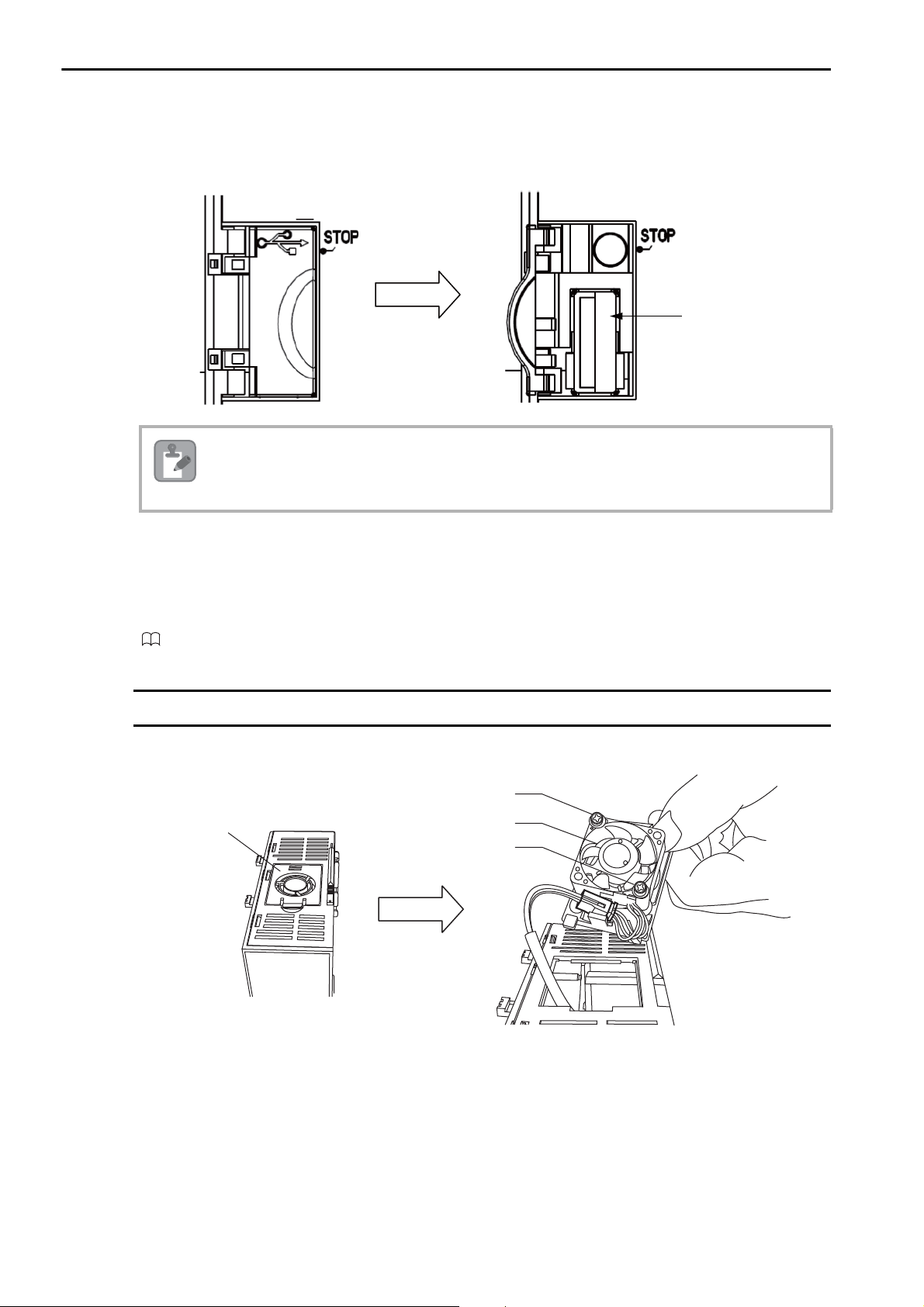
2.2 CPU Unit
Open the cover.
USB connector
Note
LOCK
Fan cover
Fan
Screw
Screw
Open the cover.
Fan
USB Connector
This connector is used to connect a USB memory device.
Before removing the USB memory device, press the STOP/SAVE switch and wait until the USB status
indicator goes out. If the USB memory device is removed while the USB status indicator is lit or flashing, the data may become corrupted.
Unit Connector
This connector is used to connect the next Unit.
Refer to the following manual for details on connecting Units.
MP2000/MP3000 Series Machine Controller System Setup Manual (Manual No.: SIEP C880725 00)
Fan
A Fan is built into the CPU-202 CPU Unit.
2-12
• Fan model: JEPMC-OP3101-E
• Screw specifications: M3 × 14 mm × 2 screws with spring washers
The Fan life is 50,000 hours minimum (at an average ambient operating temperature of 40°C). An alarm is
displayed on the CPU-202 if the Fan stops.
Page 46
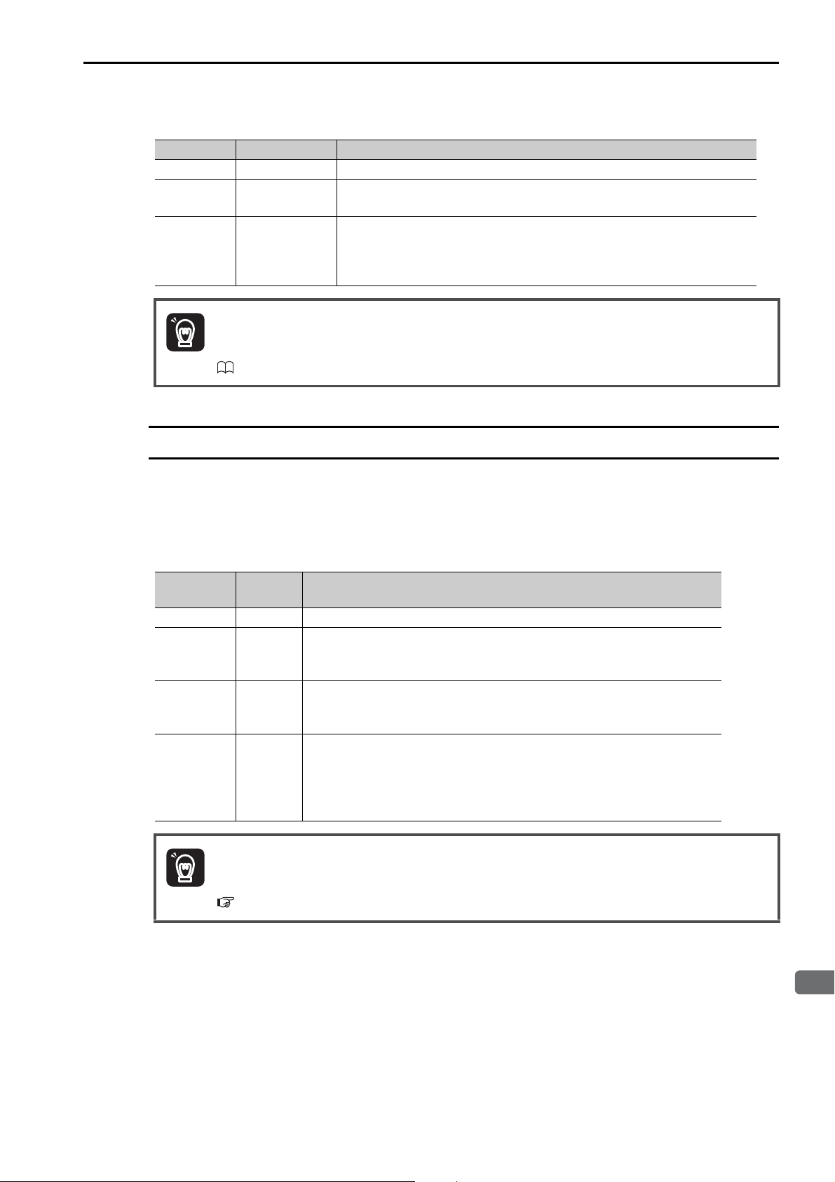
2
Appearances and Parts
There are three levels of alarms, as shown in the following table.
Important
Important
Display ALM Indicator Error Description
A.240 Lit A Fan operation failure was detected.
E.083 Lit
hLit
If the above alarms occur, turn OFF the power supply to the CPU-202 immediately and replace the
Fan.
Refer to the following manual for the Fan replacement procedure.
MP3000 Series MP3200 Troubleshooting Manual (Manual No.: SIEP C880725 01)
The Fan remained stopped for more than a minute after A.240 was detected.
(The CPU Unit will stop.)
The failsafe function was activated for E.083 (Fan Alarm) or E.082 (Temperature Warning).
(The CPU Unit will stop.)
(This alarm is displayed 5 seconds after E.083 is detected.)
Temperature Sensor
2.2 CPU Unit
Temperature Sensor
A temperature sensor is built into the CPU-202 CPU Unit.
The temperature sensor constantly monitors for abnormal temperatures in the CPU-202 Unit. If a temperature error is detected, an alarm is displayed on the CPU-202.
There are four levels of alarms, as shown in the following table.
Display
A.241 Lit A rise in the internal temperature was detected.
E.081 Lit
E.082 Lit
hLit
ALM
Indicator
The temperature continued to increase after A.241 was detected and is
approaching the permissible temperature of the internal parts.
(The CPU Unit will stop.)
The temperature continued to increase after E.081 was detected and has
reached the permissible temperature of the internal parts.
(The CPU Unit will stop.)
The failsafe function was activated for E.083 (Fan Alarm) or E.082 (Temperature Warning).
(The CPU Unit will stop.)
(This alarm is displayed if the temperature continues to increase after E.082
was detected.)
If the above alarms occur, turn OFF the power supply to the CPU-202 immediately and check the
ambient environment and installation conditions.
Refer to the following section for details on the ambient environment and installation requirements.
4.1 MP3200 Installation and Usage Conditions (page 4-2)
Error Description
2-13
Page 47
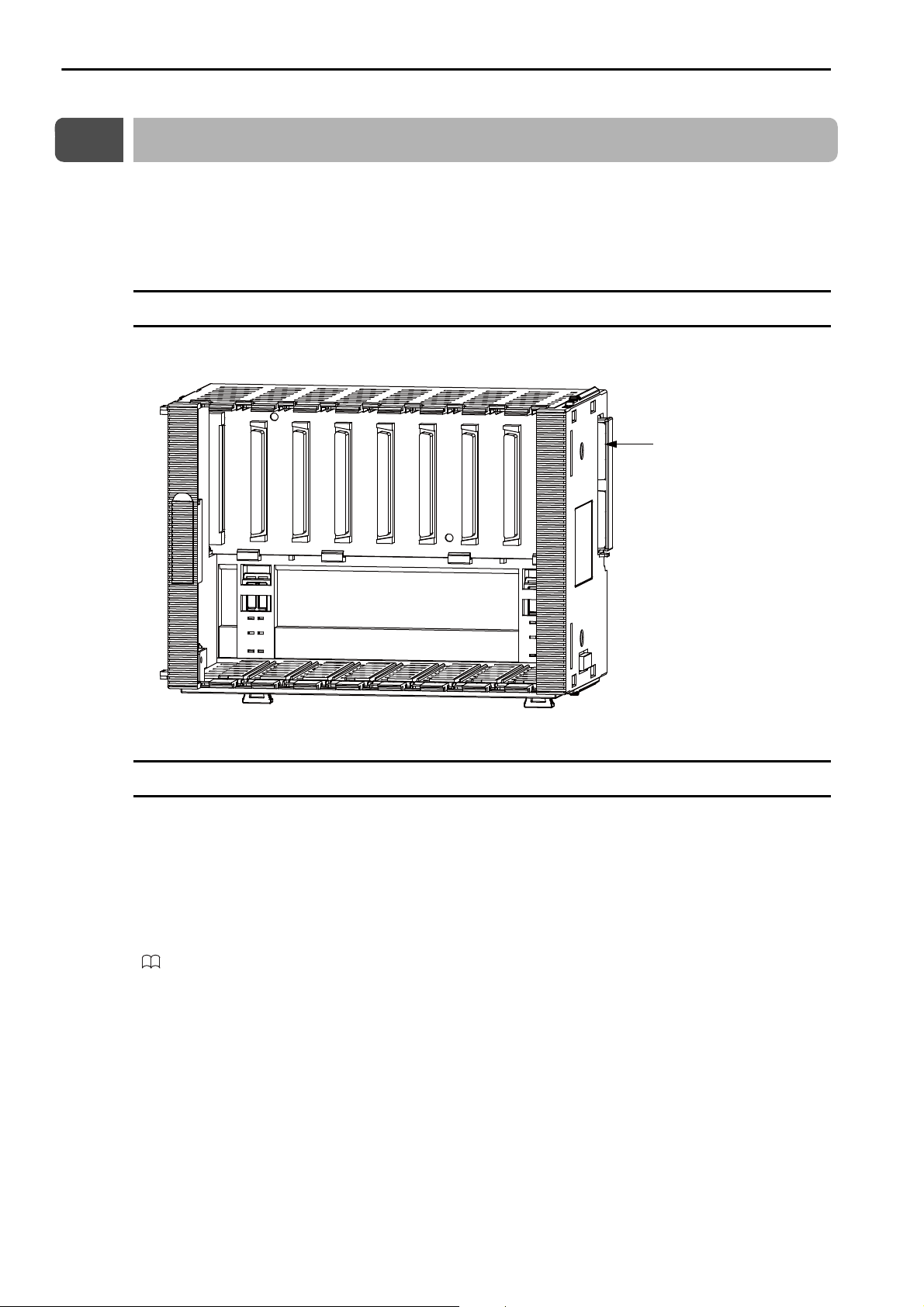
2.3 Base Units
Appearance and Part Names
2.3
Base Units
The Base Unit is used to mount Optional Modules. There are three models of Base Units, a three-slot
model, a five-slot model, and an eight-slot model.
This section shows the appearance and part names of the Base Unit and describes the connector.
Appearance and Part Names
The following figure shows the appearance of the Base Unit and a part name.
Unit connector
Connector
The Base Unit has a Unit connector.
Unit Connector
This connector is used to connect the next Unit.
Refer to the following manual for details on connecting Units.
MP2000/MP3000 Series Machine Controller System Setup Manual (Manual No.: SIEP C880725 00)
2-14
Page 48
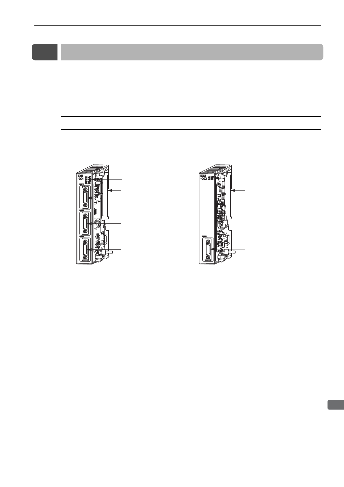
2.4 Rack Expansion Interface Unit
2
Appearances and Parts
Port 1 (Rack Expansion
Interface Unit connector)
Port 2 (Rack Expansion
Interface Unit connector)
Port 3 (Rack Expansion
Interface Unit connector)
Port 1 (Rack Expansion
Interface Unit connector)
Indicators
Indicators
Unit connector Unit connector
Main Rack Expansion
Interface Unit
Expansion Rack Expansion Interface Unit
次回用
Appearance and Part Names
2.4
Rack Expansion Interface Unit
A Rack Expansion Interface Unit is used to expand a Rack. There are two models of Rack Expansion
Interface Units, a Main Rack Expansion Interface Unit and an Expansion Rack Expansion Interface Unit.
This section shows the appearance and part names of the Rack Expansion Interface Units and describes
the indicators and connectors.
Appearance and Part Names
The following figure shows the appearance of the Rack Expansion Interface Unit and the part names.
2-15
Page 49
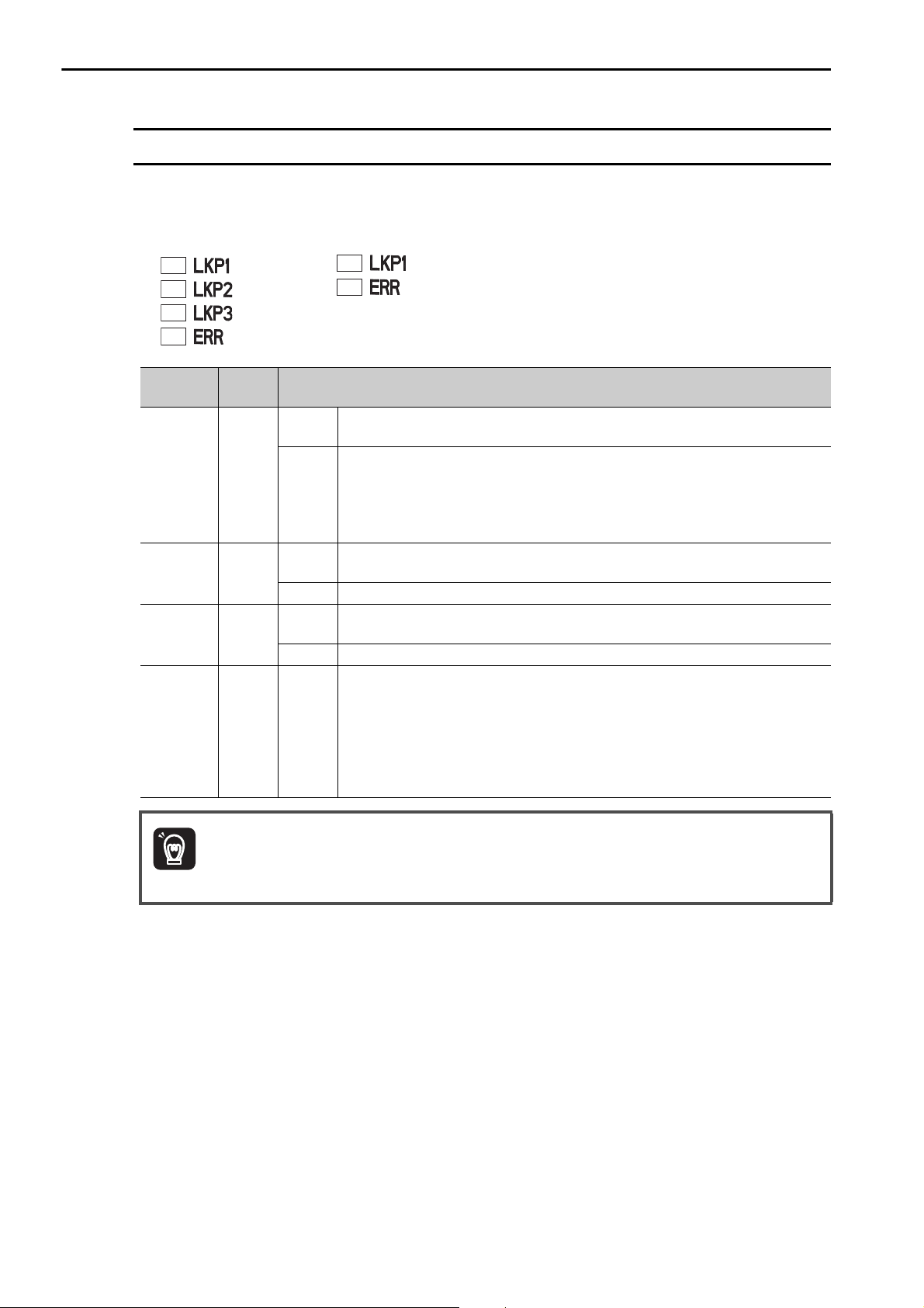
2.4 Rack Expansion Interface Unit
次回
用
次回用
Important
Indicators
Indicators
These indicators show the operating status of the Rack Expansion Interface Unit, the communications status of the cable, and the error status.
For Main Rack For Expansion Rack
Indicator
Name
LKP1 Green
LKP2 Green
LKP3 Green
ERR Red Lit
Color Status When Lit, Flashing, or Not Lit
Lit
Not lit
Lit
Not lit Same as LKP1.
Lit
Not lit Same as LKP1.
Communications are active with the Rack Expansion Interface Unit connected to
port 1.
• Consecutive communications errors occurred and communications cannot be
recovered automatically.
• The cable was disconnected or was not connected to the port.
• The current Rack Expansion Interface Unit or another Rack Expansion Interface Unit connected to it has a hardware failure.
Communications are active with the Rack Expansion Interface Unit connected to
port 2.
Communications are active with the Rack Expansion Interface Unit connected to
port 3.
• Consecutive communications errors occurred on one of the ports and communications cannot be recovered automatically.
• The cable was disconnected or was not connected. These errors are not shown
on the Main Rack Expansion Interface Unit before the connection is established.
• The current Rack Expansion Interface Unit or another Rack Expansion Interface Unit connected to it has a hardware failure.
2-16
If communications errors occur consecutively during operation, communications between the Main
Rack and Expansion Rack will stop.
Page 50

2.4 Rack Expansion Interface Unit
2
Appearances and Parts
次回用
Connectors
Connectors
The Rack Expansion Interface Unit has two connectors: Rack Expansion Interface Unit connector and
Unit connector.
Rack Expansion Interface Unit Connector
This connector is used to connect an Expansion Rack.
The Main Rack Expansion Interface Unit has three connectors (port 1, port 2, and port 3), and the Expansion Rack Expansion Interface Unit has one connector (port 1).
Unit Connector
This connector is used to connect the next Unit.
Refer to the following manual for details on connecting Units.
MP2000/MP3000 Series Machine Controller System Setup Manual (Manual No.: SIEP C880725 00)
2-17
Page 51

CPU Unit Functionality
This chapter describes the functionality of the MP3200 CPU
Units.
3
3.1
3.2
3.3
Basic Functionality . . . . . . . . . . . . . . . . . . . . . . . . 3-2
Programs . . . . . . . . . . . . . . . . . . . . . . . . . . . . . . . . . . . . . . . . 3-2
Registers . . . . . . . . . . . . . . . . . . . . . . . . . . . . . . . . . . . . . . . 3-19
Execution Scheduling . . . . . . . . . . . . . . . . . . . . . . . . . . . . . . 3-31
Scans . . . . . . . . . . . . . . . . . . . . . . . . . . . . . . . . . . . . . . . . . . 3-32
Function Modules . . . . . . . . . . . . . . . . . . . . . . . . 3-38
Self Configuration . . . . . . . . . . . . . . . . . . . . . . . . . . . . . . . . . 3-38
Communications Function Module (218IFD) . . . . . . . . . . . . 3-48
Motion Control Function Modules (SVC32 and SVR32) . . . . 3-50
The M-EXECUTOR . . . . . . . . . . . . . . . . . . . . . . . . . . . . . . . 3-56
Data Logging . . . . . . . . . . . . . . . . . . . . . . . . . . . . . . . . . . . . 3-70
USB Memory . . . . . . . . . . . . . . . . . . . . . . . . . . . . . . . . . . . . 3-85
File Transfer . . . . . . . . . . . . . . . . . . . . . . . . . . . . . . . . . . . . . 3-89
Security . . . . . . . . . . . . . . . . . . . . . . . . . . . . . . . . . . . . . . . . . 3-93
Calendar . . . . . . . . . . . . . . . . . . . . . . . . . . . . . . . . . . . . . . . . 3-93
Multi-CPU Functions . . . . . . . . . . . . . . . . . . . . . 3-94
Differences between Sub CPU Synchronization and
Slave CPU Synchronization . . . . . . . . . . . . . . . . . . . . . . . . . 3-94
Sub CPU Synchronization . . . . . . . . . . . . . . . . . . . . . . . . . . 3-95
Slave CPU Synchronization . . . . . . . . . . . . . . . . . . . . . . . . 3-108
Page 52

3.1 Basic Functionality
Programs
3.1
Basic Functionality
This section describes the basic functionality of the CPU Unit.
Programs
A program is a list of instructions to be processed by the CPU Unit.
This section describes the types of programs and gives an overview of each type.
Types of Programs
There are three types of user programs:
• Ladder programs
• Motion programs
• Sequence programs
This section describes these programs.
Ladder Programs
Ladder programs are managed as drawings (ladder diagrams) that are identified by their drawing numbers
(DWG numbers). These drawings form the basis of the user program.
Drawing Types and Hierarchical Configuration
This section describes the types of ladder drawings and their hierarchical configuration.
•Types
Ladder drawings are divided into four different types based on their purpose.
• DWG.A (Startup Drawings)
This type of ladder drawing is used to set register data. These ladder drawings are executed before
high-speed scan process drawings and low-speed scan process drawings.
• DWG.I (Interrupt Drawings)
This type of ladder drawing is used to perform processing with priority given to signals input from an
Optional Module. These ladder drawings are executed with higher priority than high-speed scan process drawings regardless of the scan cycle.
• DWG.H (High-speed Scan Process Drawings)
This type of ladder drawing is used to perform motion control or high-speed I/O control.
• DWG.L (Low-speed Scan Process Drawings)
This type of ladder drawing is used for communications with HMIs and external devices as well as for
standard I/O control.
3-2
Page 53
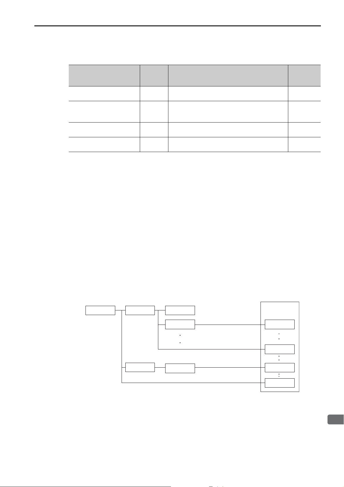
3.1 Basic Functionality
3
CPU Unit Functionality
Programs
The following table lists the priority, execution conditions, and maximum number of drawings for each
type of ladder drawing.
Maximum
Drawing Type Priority* Execution Condition
Number of
Drawings
DWG.A (Startup Drawings) 1
Power ON (These drawings are executed once when
the power supply is turned ON.)
64
External interrupt (These drawings are executed
DWG.I (Interrupt Drawings) 2
when a DI interrupt or counter match interrupt is
64
received from an Option Module.)
DWG.H (High-speed Scan
Process Drawings)
DWG.L (Low-speed Scan
Process Drawings)
* Drawings with lower numbers have higher priority.
3
4
Started at fixed intervals. (These drawings are executed once every high-speed scan.)
Started at fixed intervals. (These drawings are executed once every low-speed scan.)
200
1000
• Hierarchical Configuration
There are four types of ladder drawings: parent drawings, child drawings, grandchild drawings, and
operation error drawings.
• Parent Drawings
These drawings are automatically executed by the system program when the execution conditions are
met.
• Child Drawings
These drawings are executed when they are called from a parent drawing with a SEE instruction.
• Grandchild Drawings
These drawings are executed when they are called from a child drawing with a SEE instruction.
• Operation Error Drawings
These drawings are automatically executed by the system program when an operation error occurs.
A parent drawing cannot call a child drawing from a different type of drawing. Similarly, a child drawing cannot call a grandchild drawing from a different type of drawing. A parent drawing cannot call a
grandchild drawing directly. The parent drawing first must call the child drawing, and then the child
drawing must call the grandchild drawing. This is called the hierarchical configuration of drawings.
The following figure shows the parent-child-grandchild structure in which a program is created.
Parent
Drawing
DWG. DWG.01
Child
Drawings
DWG.nn
Note: = A, I, H, or L
Grandchild
Drawings
DWG.01.01
DWG.01.02
DWG.01.03
User Functions
FUNC-001
FUNC-006
FUNC-032
FUNC-064
3-3
Page 54
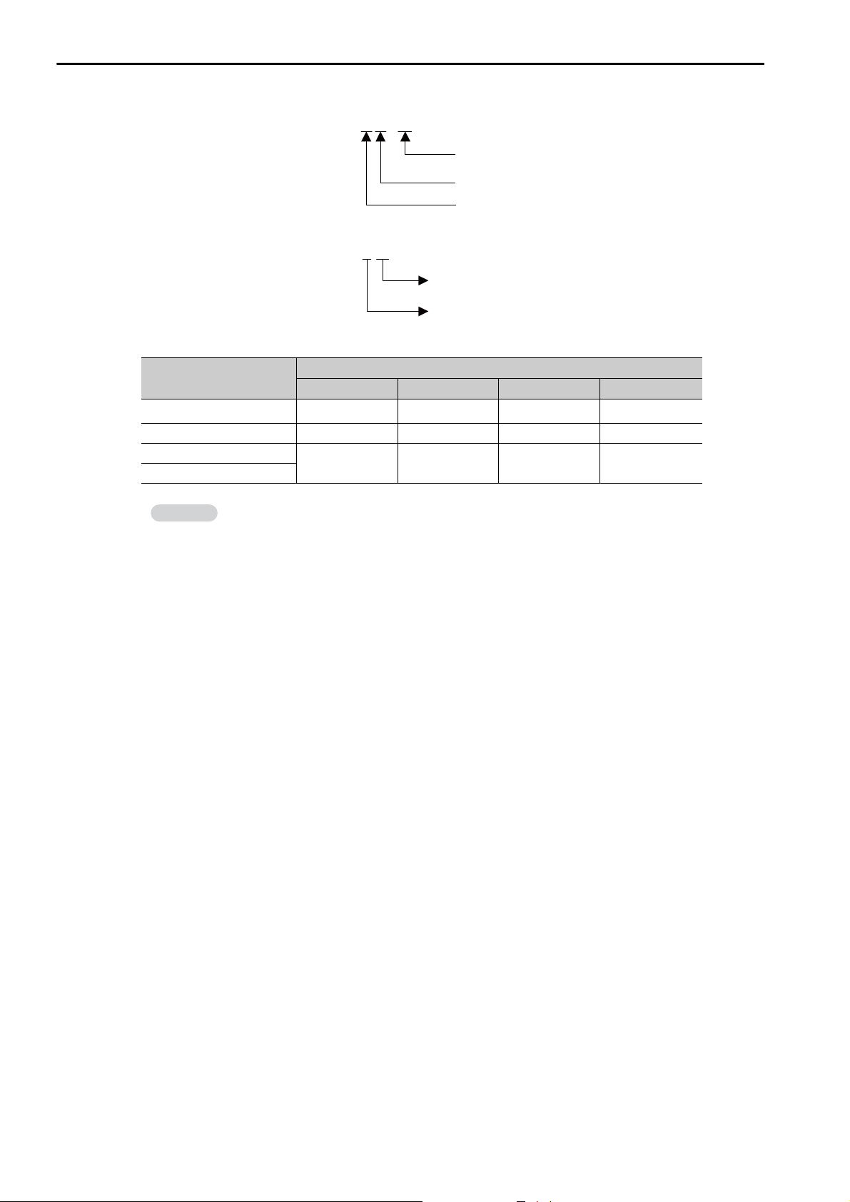
3.1 Basic Functionality
Information
Programs
DWG notation:
DWG.
Note: The following notation is used for operation error drawings.
DWG. 00
.
Grandchild drawing number
Child drawing number
Parent drawing type (A, I, H, or L)
Fixed value (00)
Parent drawing type (A, I, H, or L) of
the drawing where the error occurs
The breakdown of the number of ladder drawings in each category is given in the following table.
Drawings
DWG.A DWG.I DWG.H DWG.L
Parent Drawings 1 1 1 1
Operation Error Drawings 1 1 1 1
Child Drawings
Grandchild Drawings
Total of 62 max. Total of 62 max.
There are separate functions that can be called from the drawings as required. Functions are
executed when they are called from a parent, child, or grandchild drawing with the FUNC
instruction. You can create up to 2,000 functions.
Number of Drawings
Total of 998
max.
Total of 1,998
max.
3-4
Page 55
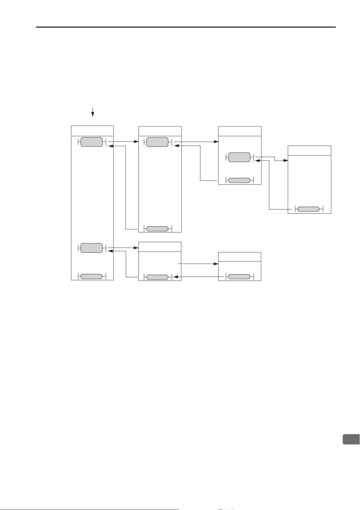
3.1 Basic Functionality
3
CPU Unit Functionality
Functions
Execution is started by the
system program when the
execution condition is met.
Parent Drawing
Child Drawings Grandchild Drawings
Execution is
automatically
started by the
system.
An operation
error occurs.
DWG.H
DWG.H01
H02
H00
DWG.H01.01
FUNC 01
SEE
H01
SEE
H02
END
END
END
END
END
END
SEE
H01.H01
FUNC
01
Programs
Execution Processing of Drawings
The drawings are executed by calling them from the top to the bottom, following the hierarchy of the
drawings. The following figure illustrates the execution processing of a high-speed scan drawing
(DWG.H).
Note: 1. The parent drawing is automatically called and executed by the system. Child drawings and grandchild drawings
are executed by calling them from a parent drawing or a child drawing using the SEE instruction.
2. You can call functions from any drawing. You can also call functions from other functions.
3. If an operation error occurs, the operation error drawing for the drawing type will be started automatically.
4. Always specify 00 as the drawing number for operation error drawings.
Functions
Functions are executed when they are called from a parent, child, or grandchild drawing with the FUNC
instruction.
Functions can be freely called from any drawing. The same function can be called simultaneously from
different types of drawings or different levels of drawings. You can also call functions from other functions that you have created.
The use of functions provides the following merits:
• Easy user program modularization
• Easy user program creation and maintenance
You can use standard functions that are provided by the system, and you can define user functions.
3-5
Page 56
3.1 Basic Functionality
Information
Important
Programs
• Standard System Functions
The following functions for communications and other purposes are provided as standard functions in the
system. You cannot change the system functions.
Function Name Name Used in MPE720
COUNTER Counter Counter
FINFOUT First-in First-out First-in First-out
TRACE Trace Trace
DTRC-RD Read Data Trace Data-Trace Read Extend
MSG-SND Send Message Send Message
MSG-SNDE Send Message Send Message Extend
MSG-RCV Receive Message Receive Message
MSG-RCVE Receive Message Extended Receive Message Extend
MOTREG-W Write Motion Register Write the Motion Parameter to Motion Register
MOTREG-R Read Motion Register Read the Motion Parameter from Motion Register
IMPORT Import Import
EXPORT Export Export
• User Functions
You can freely program the body of a user function and program the user function definitions.
A maximum of 2,000 user function drawings can be defined.
Refer to the following manual for details on how to define functions.
MP3000 Series Ladder Programming Manual (Manual No.: SIEP C880725 13)
Motion Programs
A motion program is a program that is written in a text-based motion language.
There are two types of motion programs.
Type
Main programs
Subprograms
Designation
Method
MPM
(
=
1 to
512)
MPS
(
=
1 to
512)
Features Number of Programs
• Main programs are called
from a DWG.H drawing.
• Main programs are called
from the M-EXECUTOR
program execution definitions.
Subprograms are called from a
main program.
You can create up to 512 motion programs, including the following programs:
• Motion main programs
• Motion subprograms
• Sequence main programs
• Sequence subprograms
3-6
1. The same numbers are used to manage the motion programs and sequence programs. Use a unique
number for each program.
• Motion program numbers are given in the form MPM or MPS.
• Sequence program numbers are given in the form SPM or SPS.
2. The number of motion programs that can be executed simultaneously depends on the model of the
Machine Controller. If the number of simultaneously executable programs is exceeded, an alarm
will occur (No System Work Available Error).
Page 57
3.1 Basic Functionality
3
CPU Unit Functionality
Terms
Programs
Motion Subprograms
Subprograms are created to perform common operations. They help minimizing the number of program steps and allow efficient use of memory.
Main program
MPM001 MPM002 MPM003
Call (MSEE) Call (MSEE) Call (MSEE)
MPS010
Main program Main program
The common
process is
written as a
subprogram.
Subprogram
3-7
Page 58
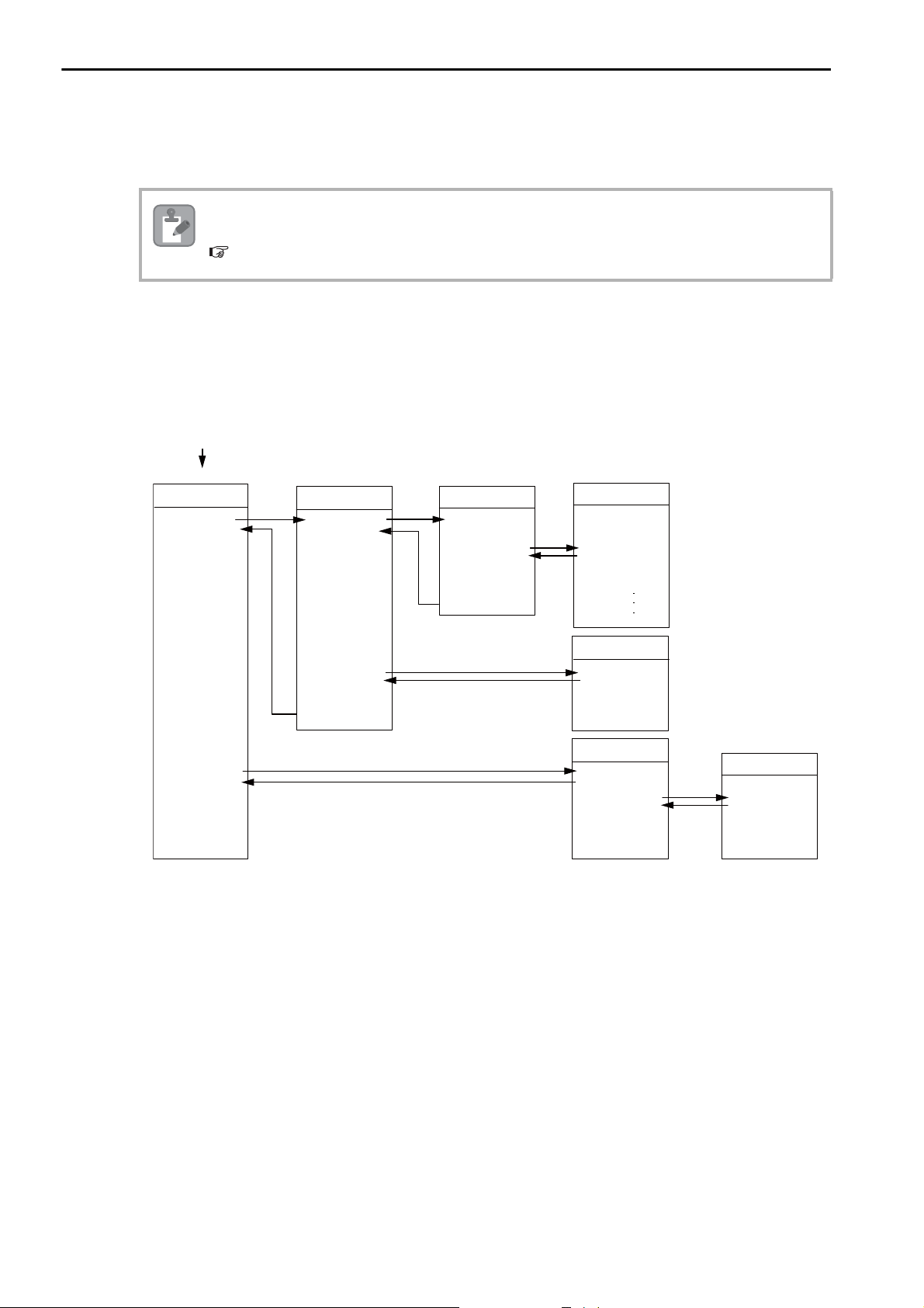
3.1 Basic Functionality
Note
MSEE
MPM001
DWG.H
SEE
H01
DEND
DWG.H01
SEE H01.01
END
DEND
END
RETEND
DEND
MPM003
MPS101
DWG.H01.01
MPM001
MPM002
MSEE
MPM002
MSEE
MPM003
MSEE
MPS101
VEL [a1]5000 [b1]..
FMX T10000000;
IAC T25;
IDC T30;
MOV [a1]300. [b1]..
MVS [a1]200. [b1]..
Execution is started by
the system program
when the execution
condition is met.
Parent drawing
Child drawing
Grandchild drawing
Motion programs
Subprogram
Programs
Motion Program Execution
Motion programs are called with an MSEE instruction from a ladder program in an H drawing.
After you create the motion program, place a Call Motion Program (MSEE) instruction in the ladder program of an H drawing. Motion programs can be called from any H drawing, regardless of whether it is a
parent, child, or grandchild drawing.
The following figure shows an execution example.
You can also register the motion program in the M-EXECUTOR (Motion Executor) to call it. Refer to
the following section for details.
The M-EXECUTOR (page 3-56)
3-8
The ladder instruction in the H drawing is executed every high-speed scan cycle according to the hierarchical organization of parent-child-grandchild drawings.
The above programming only prepares for execution of the motion program. The motion program is not
executed when the MSEE instruction is inserted. To start the motion program after inserting the MSEE
instruction, use a control signal to turn ON the Request for Start of Program Operation.
The motion program is executed in the scan cycle, but unlike ladder programs, the entire program is not
executed in a single scan. Motion programs are controlled specifically by the system’s motion management.
Page 59
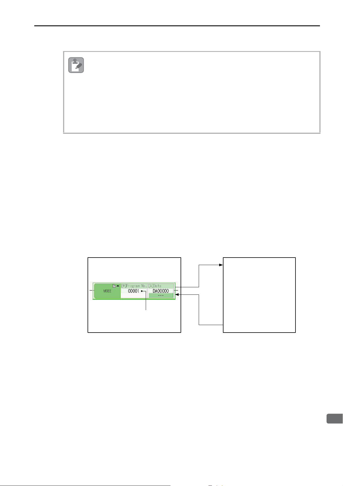
3
CPU Unit Functionality
The following points must be taken into consideration when executing motion programs.
Note
• Motion programs that are registered in the M-EXECUTOR cannot be executed with MSEE instructions.
• More than one instance of the same motion program (i.e., the same program number) cannot be executed with MSEE instructions.
• Subprograms (MPS) cannot be executed with MSEE instructions in a ladder program.
You can call subprograms only from motion programs and motion subprograms (MPM and
MPS).
• You cannot call the same subprogram more than once at the same time.
• Sequence programs (SPM or SPS) cannot be called with MSEE instructions from a ladder program.
Specifying Motion Programs
There are two methods that you can use to specify motion programs.
• Calling the motion program by specifying it directly
• Calling the motion program by specifying it indirectly
These two methods are described below.
3.1 Basic Functionality
Programs
• Calling the Motion Program by Specifying It Directly
Direct designation is used to call a motion program by specifying its program number (MPM)
directly.
To call the motion program from a ladder program with the MSEE instruction, specify the program number in the Program Number operand of the MSEE instruction.
MPM001
MSEE Instruction
MPM address
ABS;
MOV[X] _ [Y] _
MVS[X] _ [Y] _ F
IOW MB0001
MOV[X] _ [Y] _
.
.
.
Ladder Program
• Calling the Motion Program by Specifying It Indirectly
Indirect designation is used to call a motion program by specifying its number in a register.
In this method, the program (MPM) whose number is the same as the value that is stored in the register is called.
Motion Program
To call the motion program from a ladder program with an MSEE instruction, use the Program Number
operand of the MSEE instruction to specify the M or D register that indirectly designates the motion program.
3-9
Page 60
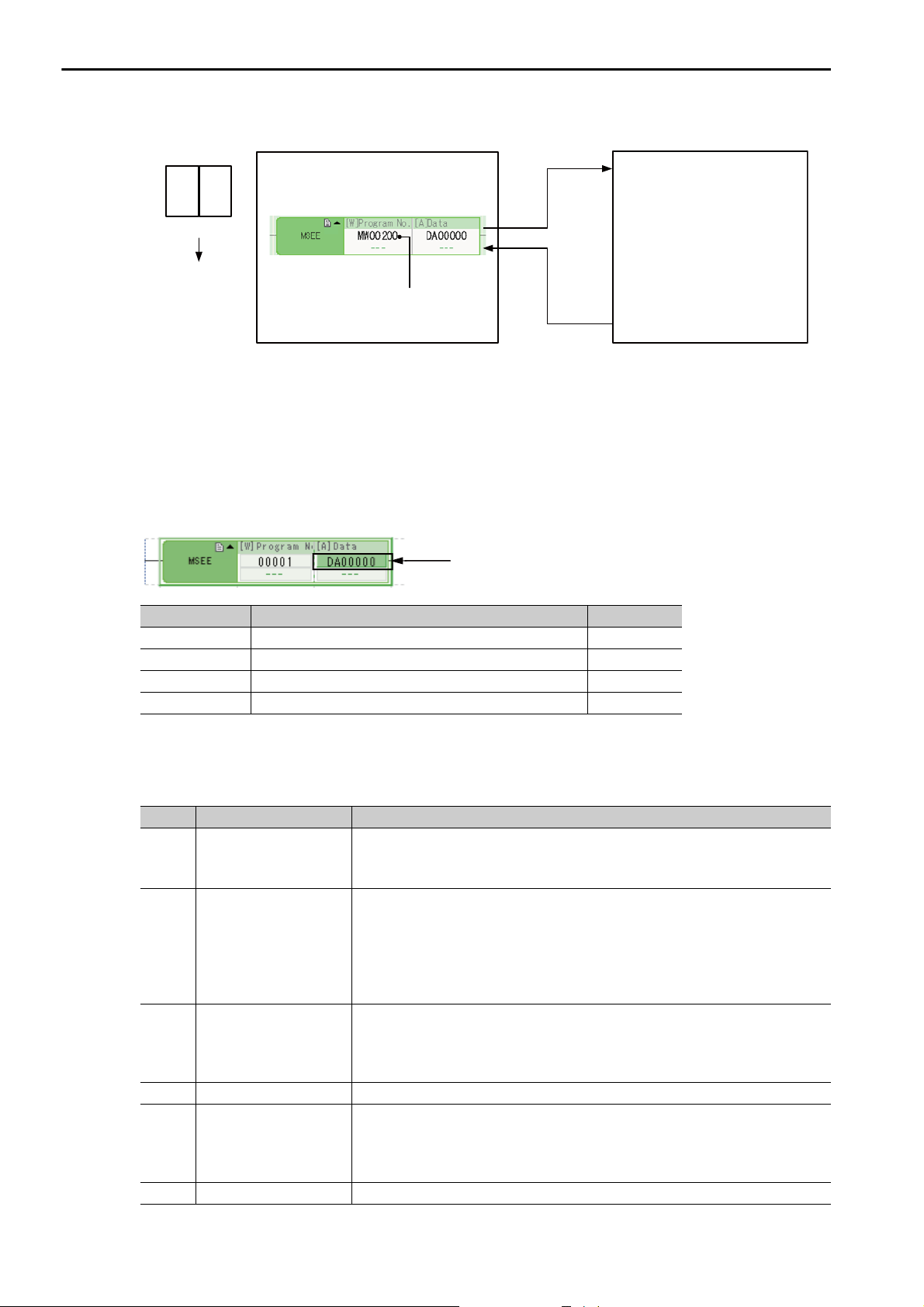
3.1 Basic Functionality
0 3
ABS;
IOW MB0001
.
.
.
MOV[X] _ [Y] _
MOV[X] _ [Y] _
MVS[X] _ [Y] _ F
* MW00200 = 3
MPM003
Setting device
The value is stored
in the MW00200
register.
MSEE Instruction
Register address
Ladder Program Motion Program
Address of first work register
(M register or D register)
Programs
Work Registers
Work registers are used to set and monitor motion programs.
The address of the first work register for the motion program that is called with an MSEE instruction is
specified in the MSEE instruction in the ladder program. The following figure shows the structure of the
work registers.
3-10
Work Register Contents Reference
1st register Motion Program Status Flags Page 3-10
2nd register Motion Program Control Signals Page 3-12
3rd register Interpolation Override Page 3-15
4th register System Work Number Page 3-15
• Status Flags
The Motion Program Status Flags give the execution condition of the motion program. The following
table describes the meanings of the Status Flags.
Bit No. Name Description
This bit is set to 1 when a motion program is running.
Bit 0 Program Executing
Bit 1 Program Paused
Bit 2
Program Stopped for
Stop Request
Bit 3 Reserved for system. −
Bit 4
Program Single-block
Execution Stopped
Bit 5 Reserved for system. −
0: Motion program is stopped.
1: Motion program is running.
This bit is set to 1 when execution of a motion program is paused by a Request
for Pause of Program.
After a Request for Pause of Program control signal is input, it is confirmed
that the axis decelerated to a stop and then the status flag is turned ON.
0: Program is not stopped by a pause request.
1: Program is stopped by a pause request.
This bit is set to 1 when execution of a motion program is stopped by a Request
for Stop of Program.
0: Program is not stopped by a stop request.
1: Program is stopped by a stop request.
This bit is set to 1 when execution of a single block is stopped in Debug Operation Mode.
0: Single block execution is not stopped.
1: Single block execution is stopped.
Continued on next page.
Page 61

3.1 Basic Functionality
3
CPU Unit Functionality
Programs
Continued from previous page.
Bit No. Name Description
Bit 6 Reserved for system. −
Bit 7 Reserved for system. −
This bit is set to 1 when a program alarm occurs.
When this bit is set to 1, details on the error will be displayed in the Error Infor-
Bit 8 Program Alarm
Bit 9
Bit A Reserved for system. −
Bit B Debug Operation Mode
Bit C Program Type
Bit D Start Request History
Bit E
Bit F
Note: If a program alarm occurs, motion program error information is provided in the Error Information Dialog Box and given in
Program Stopped at
Breakpoint
No System Work Error
or Execution Scan Error
Main Program Number
Limit Exceeded Error
the S registers.
mation Dialog Box and are given in the S registers.
0: There is no program alarm.
1: A program alarm occurred.
This bit is set to 1 when execution of a program stops at a breakpoint in Debug
Operation Mode.
0: Not stopped at a breakpoint.
1: Stopped at a breakpoint.
This bit is set to 1 when a program is running in Debug Operation Mode.
0: Not in Debug Operation Mode (Normal Execution Mode).
1: In Debug Operation Mode.
This bit reports whether the program that is being executed is a motion program
or a sequence program.
0: Motion program
1: Sequence program
This bit is set to 1 when the Request for Start of Program Operation is ON.
0: Request for Start of Program Operation is OFF.
1: Request for Start of Program Operation is ON.
This bit is set to 1 when a system work number that was needed to execute a
motion program could not be obtained, or when an MSEE instruction is programmed in a drawing other than a DWG.H.
0: There is no system work error or execution scan error.
1: A no system work error or execution scan error occurred.
This bit is set to 1 when the specified motion program number is out of range.
Motion program number range:1 to 512
0: There is no motion program number error.
1: A motion program number error occurred.
3-11
Page 62
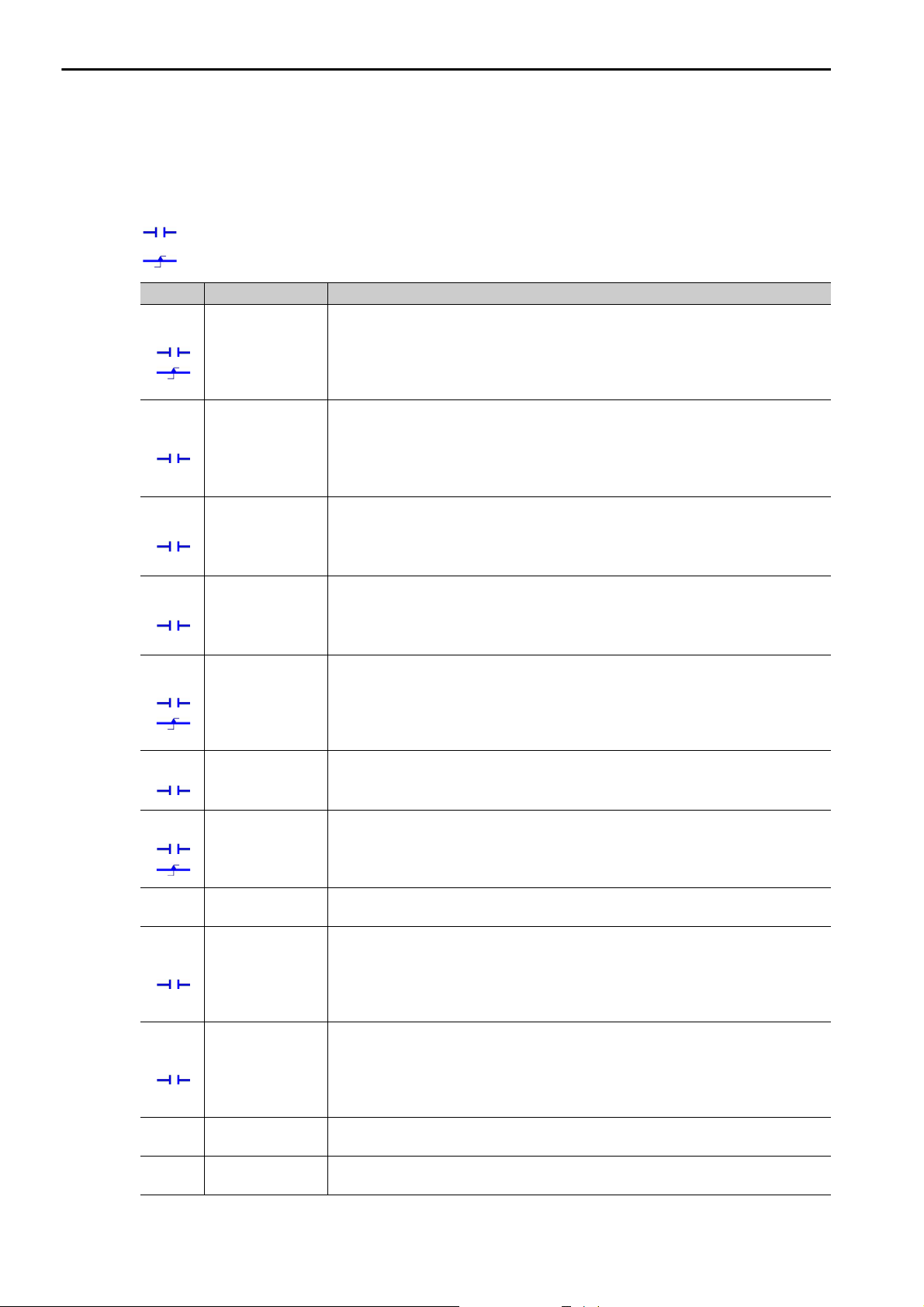
3.1 Basic Functionality
Programs
• Control Signals
To control the execution of a motion program, you must input program control signals (Request for Start
of Program Operation, or Request for Stop of Program, etc.). The following table describes the control signals for motion programs.
: This mark indicates that the signal must be kept ON until the system acknowledges it.
: This mark indicates that the signal needs to be turned ON only for one high-speed scan.
Bit No. Name Description
Bit 0
Bit 1
Bit 2
Bit 3
Bit 4
Bit 5
Bit 6
Bit 7
Bit 8
Bit 9
Bit A, B
Bit C
Request for Start
of Program Operation
Request for Pause
of Program
Request for Stop
of Program
Program Singleblock Mode
Selection
Program Singleblock Start
Request
Program Reset
and Alarm Reset
Request
Request for Start
of Continuous
Program Operation
Reserved for system.
Skip 1 Information
Skip 2 Information
Reserved for system.
Reserved for system.
This bit makes a request to start execution of a motion program. The motion program starts when this bit changes from 0 to 1. This bit is ignored when there is a
motion program alarm.
0: Turn OFF the request to start the program.
1: Turn ON the request to start the program.
This bit makes a request to pause execution of a motion program.
Execution of the program that was paused will resume when the pause request is
turned OFF.
0: Turn OFF the request to pause the program (i.e., cancel the pause).
1: Turn ON the request to pause the program.
This bit makes a request to stop execution of a motion program.
A motion program alarm occurs if this bit is set to 1 while the axis is in motion.
0: Turn OFF the request to stop the program.
1: Turn ON the request to stop the program.
This bit makes a request to select Program Single-block Execution Mode.
This mode can be used in place of Debug Operation Mode.
0: Turn OFF the request to select single-block mode.
1: Turn ON the request to select single-block mode.
When this bit is changed from 0 to 1, program execution changes to single-block
execution (step execution). This bit is valid only when bit 3 (Program Single-block
Mode Selection) in the control signals is set to 1.
0: Turn OFF the request to start the program in single-block mode.
1: Turn ON the request to start the program in single-block mode.
This bit resets motion programs and alarms.
0: Turn OFF the request to reset the program and alarms.
1: Turn ON the request to reset the program and alarms.
This bit makes a request to resume execution of a program that was stopped by a
Request for Stop of Program.
0: Turn OFF the request to resume the program.
1: Turn ON the request to resume the program.
−
If this bit changes to 1 while an axis is in motion due to a SKP instruction (when the
skip input signal selection is set to SS1), the axis will decelerate to a stop, and the
reference in the remaining travel distance will be canceled.
0: Turn OFF the skip 1 signal.
1: Turn ON the skip 1 signal.
If this bit changes to 1 while an axis is in motion due to a SKP instruction (when the
skip input signal selection is set to SS2), the axis will decelerate to a stop, and the
reference in the remaining travel distance will be canceled.
0: Turn OFF the skip 2 signal.
1: Turn ON the skip 2 signal.
−
−
Continued on next page.
3-12
Page 63

3.1 Basic Functionality
3
CPU Unit Functionality
Continued from previous page.
Bit No. Name Description
Bit D
System Work
Number Setting
Bit E
Interpolation
Override Setting
Bit F
*1. System Work Number Setting
• When the Motion Program Is Registered in M-EXECUTOR:
• When a Motion Program Is Called from a Ladder Program with an MSEE Instruction:
*2. Interpolation Override Setting
Note: 1. Use the specified signal types for the ladder program inputs.
Reserved for system.
The system work number cannot be specified. The system will use the definition number as the system work number.
OFF: The system will use an automatically acquired system work number. The system work number will be different each
time.
ON: The work number that is specified by the system will be used.
However, if the work number is assigned to the M-EXECUTOR, a No System Work Available Error (Status Flag
Bit E) is reported.
OFF: The interpolation override is always 100%.
ON: The interpolation override in the parameter setting is used.
2. At startup, the motion programs for which the Request for Start of Program Operation control signals are ON
will be executed.
To specify a system work number, set this bit to 1.
0: Do not specify a system work number.
*1
1: Specify a system work number.
To specify an interpolation override, set this bit to 1.
0: Do not specify an interpolation override.
*2
1: Specify an interpolation override.
−
Programs
3-13
Page 64
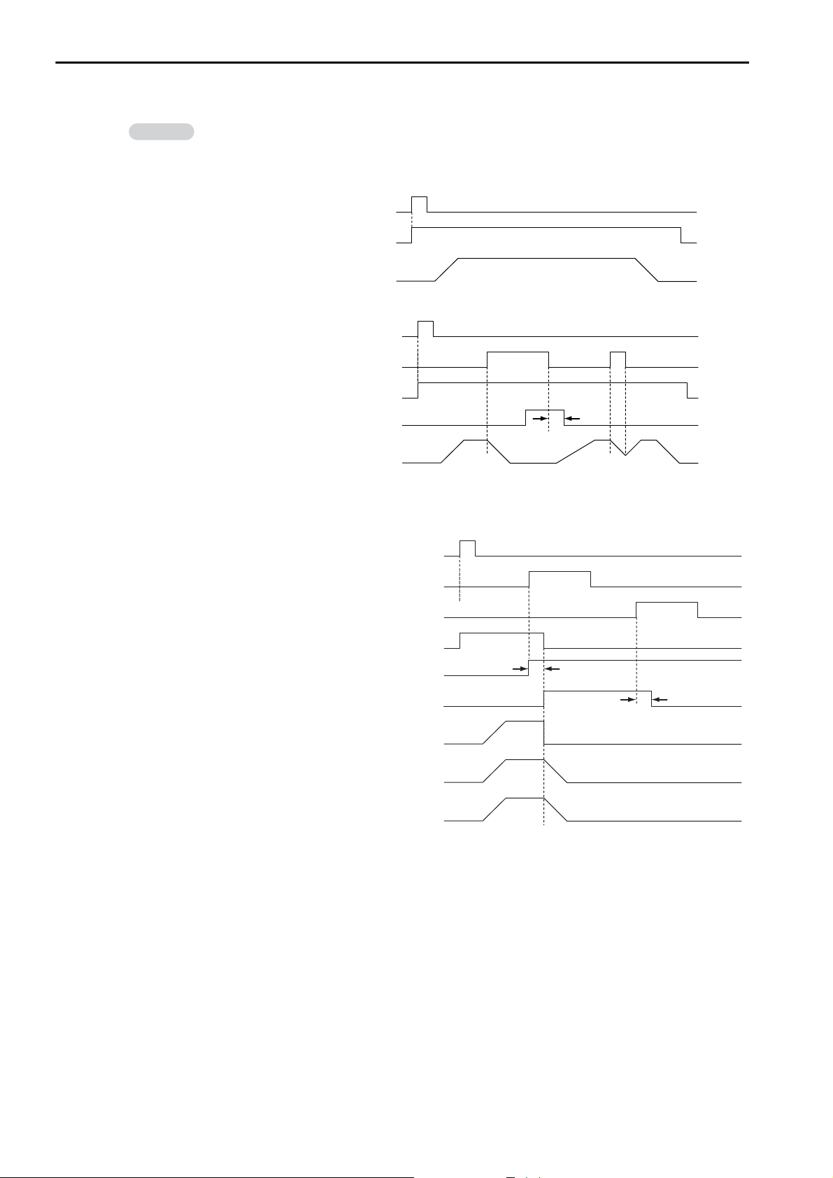
3.1 Basic Functionality
Example
Control signal: Request for Start of
Program Operation
Status flag: Program Executing
Axis operation: Pulse distribution
Control signal: Request for Start of
Program Operation
Status flag: Program Executing
Axis operation: Pulse distribution
Control signal: Request for Pause of
Program
Status flag: Program Paused
1 scan*
Control signal: Request for Start of
Program Operation
Status flag: Program Executing
Axis operation: Pulse distribution for
Positioning instruction
Control signal: Request for Stop of Program
Axis operation: Pulse distribution for
Zero Point Return instruction
Axis operation: Pulse distribution for
Interpolation instruction
Status flag: Program Stopped for
Stop Request
Status flag: Program Alarm
Control signal: Program Reset and
Alarm Reset Request
1 scan*
1 scan
Programs
Timing chart examples for axis operations and status flags after a control signal is input are provided below.
Request for Start of Program Operation
Request for Pause
* Status flags related to control signal input are updated after one scan.
Request for Stop
* Status flags related to control signal input are updated after one scan.
3-14
Page 65
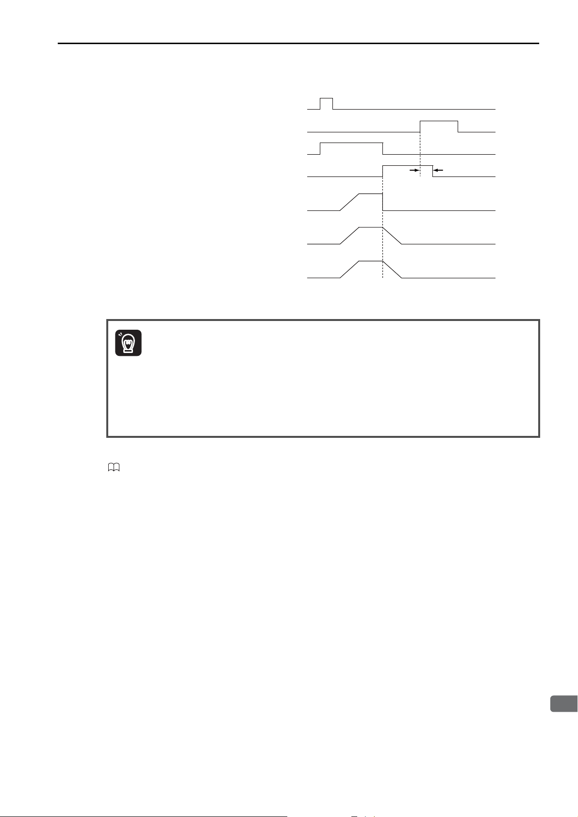
3
CPU Unit Functionality
If a Motion Program Alarm Occurs
Control signal: Request for Start of
Program Operation
Status flag: Program Alarm
Status flag: Program Executing
Axis operation: Pulse distribution for
Interpolation instruction
Control signal: Program Reset and Alarm
Reset Request
Axis operation: Pulse distribution for
Positioning instruction
Axis operation: Pulse distribution for
Zero Point Return instruction
1 scan*
Important
* Status flags related to control signal input are updated after one scan.
3.1 Basic Functionality
Programs
1. If the Request for Stop of Program control signal is turned ON while the axis is being controlled for
a motion language instruction, an alarm will occur.
2. If the Request for Stop of Program control signal is turned ON while the axis is being controlled for
an interpolation motion language instruction, the axes will stop immediately. To perform a deceleration stop, use the Request for Pause of Operation control signal.
3. The Request for Pause of Program control signal is not acknowledged while a Zero Point Return
(ZRN) instruction is being executed. To stop the operation, use the Request for Stop of Program
control signal.
4. If a motion program alarm occurs while an axis is in motion, the axis stops immediately.
Refer to the following manuals for details on programming examples for controlling motion programs.
MP3000 Series Motion Programming Manual (Manual No.: SIEP C880725 14)
• Interpolation Override
An interpolation override allows you to change the output ratio of the axis movement speed reference for
interpolation motion language instructions.
Set the override value to use when executing interpolation instructions (MVS, MCW, MCC, or SKP).
The interpolation override is valid only when bit E (Interpolation Override Setting) in the control signals is
ON.
The setting range of the interpolation override is 0 to 32,767.
Unit: 1 = 0.01%
•System Work Numbers
When you call a motion program from a ladder program with the MSEE instruction, set the system work
number to use to call the motion program. This system work number is valid only when bit D (System
Work Number Setting) of the control signals is ON.
Setting range: 1 to 32
3-15
Page 66
3.1 Basic Functionality
Important
Information
Programs
Monitoring Motion Program Execution Information
The execution information for motion programs can be monitored using the S registers (SW03200 to
SW05119 and SW08192 to SW09125).
The execution information is monitored differently, depending on whether the motion program is called
from a ladder program with an MSEE instruction, or the motion program is registered in the M-EXECUTOR program execution definitions.
This section describes these two monitoring methods.
When using MSEE instructions in ladder programs along with the M-EXECUTOR, do not specify the
system work numbers that are for the M-EXECUTOR in the MSEE instructions in the ladder programs.
If you specify one, a No System Work Error will occur.
System work numbers for the M-EXECUTOR: 0 to the set value of the number of program definitions
You cannot set the system work numbers when you use the M-EXECUTOR. The system will use
system work numbers that are the same as the definition numbers.
• When the Motion Program Is Called from the Ladder Program with an MSEE Instruction
When a motion program is called from the ladder program with an MSEE instruction, the monitoring
method depends on the setting of bit D (System Work Number Setting) in the Motion Program Control
Signals.
Bit D (System Work Number
Setting) in the Control Signal
Word for Motion Programs
ON
OFF
The execution information is reported in the Work n Program Information
registers (SW03264 to SW05119 and SW08192 to SW09125).
For example, if the system work number is 1, you can monitor the execution
information of the motion program with the Work 1 Program Information
registers (SW03264 to SW03321).
The system automatically determines the system work number to use.
You can check the work numbers that are in use in the Active Program Numbers registers (SW03200 to SW03231).
For example, if MPM001 is the motion program to be monitored and
SW03202 contains a 1, the system work number is 3. You can therefore monitor the execution information of the motion program with the Work 3 Pro-
gram Information registers (SW03380 to SW03437).
Monitoring
• When the Motion Program Is Registered in the M-EXECUTOR Program Execution Definitions:
When the motion program is registered in the M-EXECUTOR program execution definitions, the system
work number used will be the same as the program execution registration number in the M-EXECUTOR.
3-16
For example, if the motion program is registered for execution as number 3, system work number 3 is
used. You can therefore monitor the execution information of the motion program with the Work 3 Program Information registers (SW03380 to SW03437).
Page 67
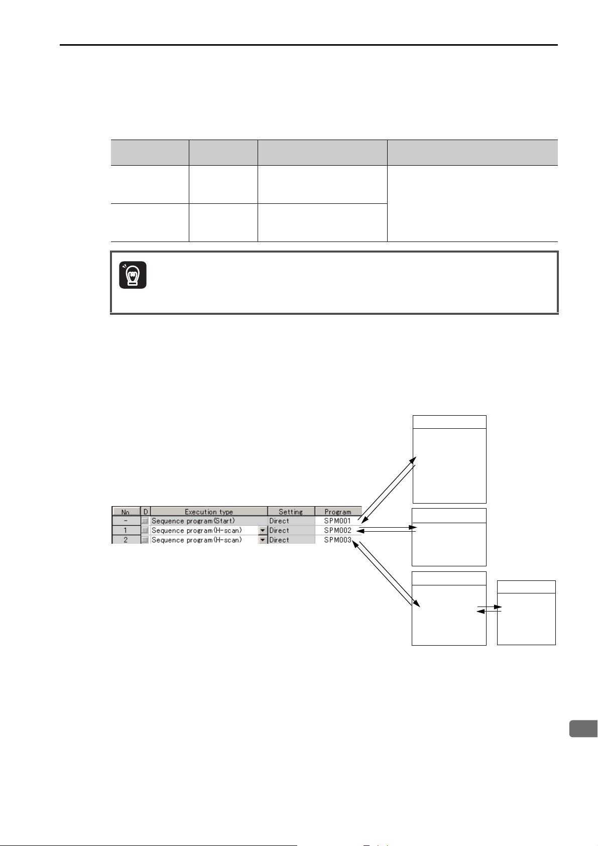
3
CPU Unit Functionality
Sequence Programs
Important
A sequence program is written in a text-based motion language.
There are two types of sequence programs.
3.1 Basic Functionality
Programs
Type
Main programs
Subprograms
Designation
Method
SPM
(=1 to
512)
SPS
(=1 to
512)
Features Number of Programs
Main programs are called from
the M-EXECUTOR program
execution definitions.
Subprograms are called from a
main program.
You can create up to 512 motion programs, including the following programs:
• Motion main programs
• Motion subprograms
• Sequence main programs
• Sequence subprograms
The same numbers are used to manage the sequence programs and motion programs.
Use a unique number for each program.
• Motion program numbers are given in the form MPM or MPS.
• Sequence program numbers are given in the form SPM or SPS.
Sequence Program Execution
A sequence program is executed by registering it in the M-EXECUTOR execution definitions.
The sequence programs are executed in ascending order.
The following figure shows an execution example.
Sequence programs
SPM001
IF MW000<32767;
MW000=MW000+1;
ELSE;
MW000;
IEND;
M-EXECUTOR Program Execution Definitions
END
END
END
SPM002
SPM003
SSEE
SPS101
Subprogram
SPS101
RET
If the execution type is set to an H-scan sequence program or L-scan sequence program, then the program
will be executed as soon as the definition is saved. If the execution type is set to a startup sequence program, then the program will be executed the next time when the power supply is turned ON.
3-17
Page 68
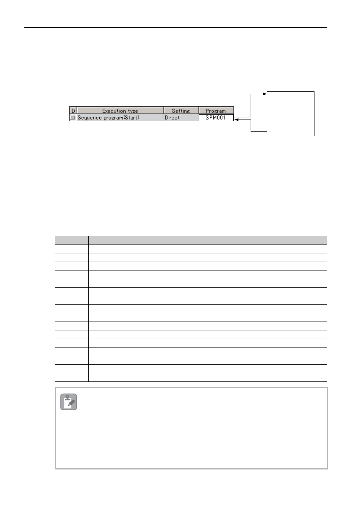
3.1 Basic Functionality
SPM001
IF MW000<32767;
MW000=MW000+1;
ELSE;
MW000;
IEND;
Sequence program
M-EXECUTOR Program Execution Definitions
Note
Programs
Specifying Sequence Programs
Sequence programs must be specified directly. Indirect designations cannot be used.
Specify the program number of the sequence program to execute (SPM).
Work Registers
Work registers are used to monitor sequence programs.
The work registers have Status Flags inside the M-EXECUTOR control registers, in the same way as
motion programs that are registered in the M-EXECUTOR.
• Sequence Program Status Flags
The Sequence Program Status Flags give the execution condition of the sequence program.
The following table describes the meanings of the Status Flags.
Bit No. Name Status
0 Program Executing Program is being executed.
1 − Reserved for system.
2 − Reserved for system.
3 − Reserved for system.
4 − Reserved for system.
5 − Reserved for system.
6 − Reserved for system.
7 − Reserved for system.
8 Program Alarm There is a program alarm.
9 Program Stopped at Breakpoint Execution is stopped at a breakpoint.
A − Reserved for system.
B Debug Operation Mode The program is in Debug Mode (EWS debugging).
C Program Type Program Type, 1: Sequence program
D Start Request History There is a request to start program execution.
E − Reserved for system.
F − Reserved for system.
Sequence Program Alarms
When an error is detected, bit 8 (Program Alarm) turns ON in the Status Flags in the M-EXECUTOR
control registers.
When the error is removed, this bit turns OFF.
The following errors can occur.
• The called program is not registered.
• The called program is not a sequence program.
• The called program is not a subprogram (a main program was called).
• Called Program Number Limit Exceeded Error
• Too Many Nesting Levels Error
3-18
Page 69
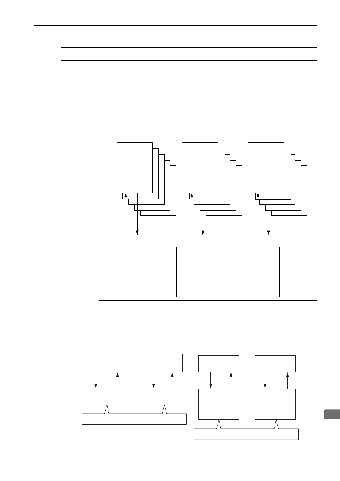
3.1 Basic Functionality
3
CPU Unit Functionality
H01
FUNC01 FUNC02
H
Parent drawing
# registers
Child drawing
# registers
User function
X registers
User function
X registers
D registers D registers
Y registers
Z registers
# registers
D registers
Y registers
Z registers
# registers
D registers
These registers cannot be shared between
different drawings.
These registers cannot be shared between
different drawings.
Registers
Registers
Registers are areas that store data within the Machine Controller. Variables are registers with labels (variable names).
There are two kinds of registers: global registers that are shared between all programs, and local registered
that are used only by a specific program.
Global Registers
Global registers are shared by ladder programs, user functions, motion programs, and sequence programs.
Memory space for global registers is reserved by the system for each register type.
Ladder
program
S registers
65,535
words
M registers
1,048,576
words
User functions Motion
Global registers
G registers
2,097,152
words
I registers
65,536
words
Input data +
Monitor
parameters +
CPU interface
inputs
programs/
sequence
programs
O registers
65,536
words
Output data +
Setting
parameters +
CPU interface
outputs
C registers
16,384
words
Local Registers
Local registers can be used within each specific drawing. These registers cannot be shared by other drawings. Local registers are stored in the program memory for each drawing.
Ladder Program Conceptual Diagram
3-19
Page 70
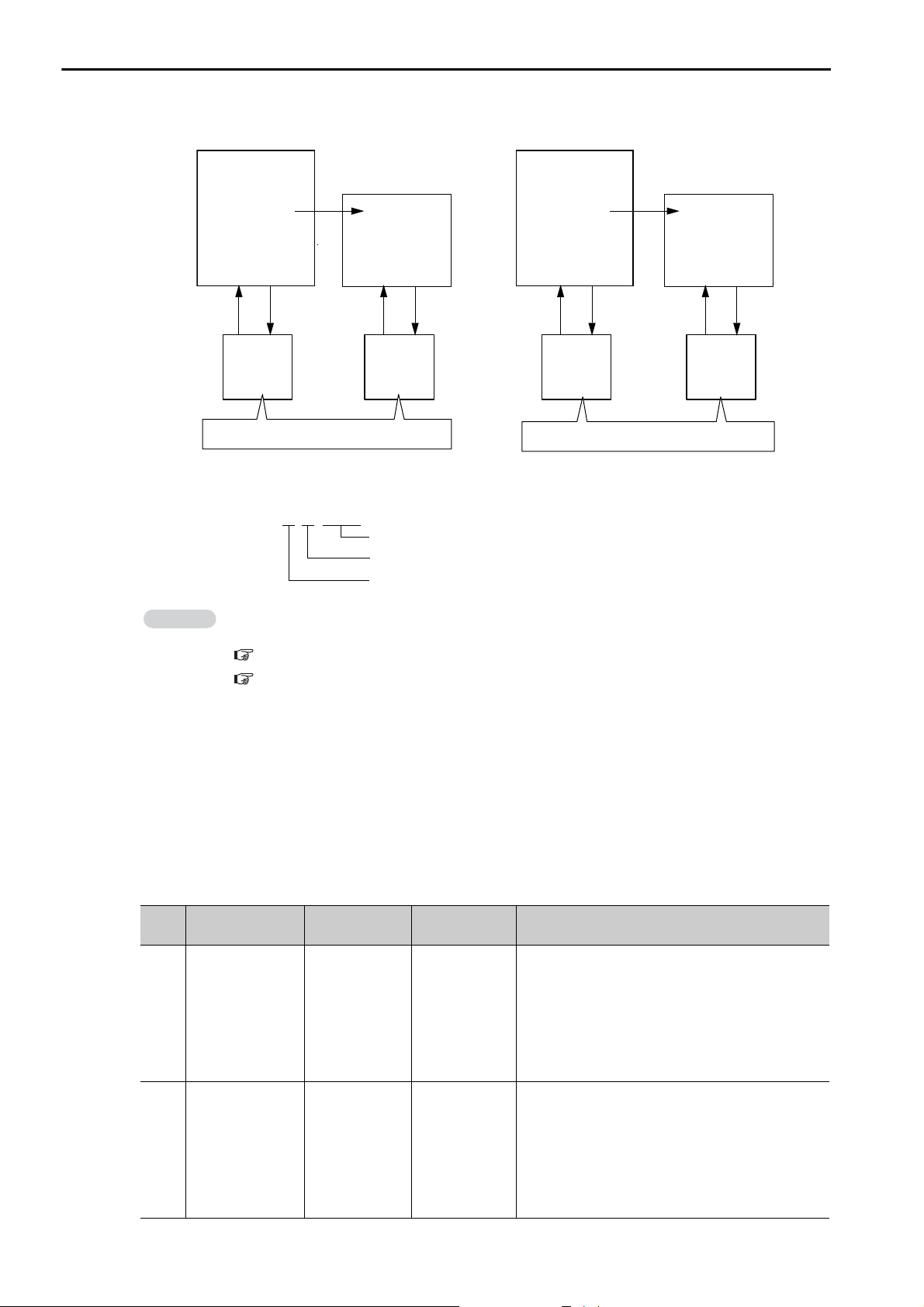
3.1 Basic Functionality
Register address = S W 00000
Range (The number of digits depends on the register type and data type.)
Data type
Register type
Information
Registers
Motion Program Conceptual Diagram
Motion program
(MPM001)
MSEE MPS002;
D registers
(DW00000
to
DW00031)
D registers cannot be shared between
different drawings.
Subprogram
(MPS002)
D registers
(DW00000
to
DW00031)
Structure of Register Addresses
You can also use index registers or array registers as variables to address specific registers.
Refer to the following sections for details.
Index Registers (i, j) (page 3-27)
Array Registers ([ ]) (page 3-30)
Sequence program
(SPM003)
SSEE SPS004;
D registers
(DW00000
to
DW00031)
D registers cannot be shared between
different drawings.
Subprogram
(SPS004)
D registers
(DW00000
to
DW00031)
Register Types
This section describes global and local registers.
Global Registers
Global registers are shared by ladder programs, user functions, motion programs, and sequence programs.
In other words, the operation results of a ladder program can be used by other user functions, motion programs, or sequence programs.
Type Name
S
M
3-20
System registers
(S registers)
Designation
Method
SBnnnnnh,
SWnnnnn,
SLnnnnn,
SQnnnnn,
SFnnnnn,
SDnnnnn,
SAnnnnn
Usable Range Description
These registers are prepared by the system. They
report the status of the Machine Controller and
SW00000 to
SW65534
other information.
The system clears the registers from SW00000 to
SW00049 to 0 at startup.
They have a battery backup.
MBnnnnnnnh,
MWnnnnnnn,
Data registers
(M registers)
MLnnnnnnn,
MQnnnnnnn,
MFnnnnnnn,
MW0000000
to
MW1048575
These registers are used as interfaces between programs.
They have a battery backup.
MDnnnnnnn,
MAnnnnnnn
Continued on next page.
Page 71

3
CPU Unit Functionality
Type Name
G G registers
Input registers
I
(I registers)
Output registers
O
(O registers)
Constant registers
C
(C registers)
Note: n: decimal digit, h: hexadecimal digit
Designation
Method
GBnnnnnnnh,
GWnnnnnnn,
GLnnnnnnn,
GQnnnnnnn,
GFnnnnnnn,
GDnnnnnnn,
GAnnnnnnn
IBhhhhhh,
IWhhhhh,
ILhhhhh,
IQhhhhh,
IFhhhhh,
IDhhhhh,
IAhhhhh
OBhhhhhh,
OWhhhhh,
OLhhhhh,
OQhhhhh,
OFhhhhh,
ODhhhhh,
OAhhhhh
CBnnnnnh,
CWnnnnn,
CLnnnnn,
CQnnnnn,
CFnnnnn,
CDnnnnn,
CAnnnnn
3.1 Basic Functionality
Continued from previous page.
Usable Range Description
GW0000000 to
GW2097151
IW00000 to
IW07FFF,
IW10000 to
IW17FFF
IW08000 to
IW0FFFF
IW20000 to
IW21FFF
OW00000 to
OW07FFF,
OW10000 to
OW17FFF
OW08000 to
OW0FFFF
OW20000 to
OW21FFF
CW00000 to
CW16383
These registers are used as interfaces between programs.
They do not have a battery backup.
These registers are used for input data.
These registers store the motion monitor parameters.
These registers are used for Motion Modules.
These registers are used as interfaces between
CPU Units when Expansion Racks are used (CPU
interface registers).
These registers are used for output data.
These store the motion setting parameters.
These registers are used for Motion Modules.
These registers are used as interfaces between
CPU Units when Expansion Racks are used (CPU
interface registers).
These registers can be read in programs but they
cannot be written.
The values are set from the MPE720.
Registers
3-21
Page 72

3.1 Basic Functionality
Registers
Local Registers
Local registers are valid within only one specific program. The local registers in other programs cannot be
accessed.
You specify the usable range from the MPE720.
Type Name
# # registers
D D registers
Function
X
input registers
Function out-
Y
put registers
Function
Z
internal registers
Function
A
external registers
Note: n: decimal digit, h: hexadecimal digit
Designation
Method
#Bnnnnnh,
#Wnnnnn,
#Lnnnnn,
#Qnnnnn,
#Fnnnnn,
#Dnnnnn,
#Annnnn
DBnnnnnh,
DWnnnnn,
DLnnnnn,
DQnnnnn,
DFnnnnn,
DDnnnnn,
DAnnnnn
XBnnnnnh,
XWnnnnn,
XLnnnnn,
XQnnnnn,
XFnnnnn,
XDnnnnn
YBnnnnnh,
YWnnnnn,
YLnnnnn,
YQnnnnn,
YFnnnnn,
YDnnnnn
ZBnnnnnh,
ZWnnnnn,
ZLnnnnn,
ZQnnnnn,
ZFnnnnn,
ZDnnnnn
ABnnnnnh,
AWnnnnn,
ALnnnnn,
AQnnnnn,
AFnnnnn,
ADnnnnn
Description Features
These registers can be read in programs but they cannot be
written.
The values are set from the MPE720.
These registers can be used for general purposes within a
program.
By default, 32 words are reserved for each program.
The default value after startup depends on the setting of
the D Register Clear when Start option.
Refer to the following section for details.
Setting the D Register Clear When Start Option (page 3-23)
These registers are used for inputs to functions.
• Bit inputs: XB000000 to XB00000F
• Integer inputs: XW00001 to XW00016
• Double-length integers: XL00001 to XL00015
• Quadruple-length integers: XQ00001 to XQ00013
• Real numbers: XF00001 to XF00015
• Double-precision real numbers: XD00001 to XD00013
These registers are used for outputs from functions.
• Bit outputs: YB000000 to YB00000F
• Integer outputs: YW00001 to YW00016
• Double-length integers: YL00001 to YL00015
• Quadruple-length integers: YQ00001 to YQ00013
• Real numbers: YF00001 to YF00015
• Double-precision real numbers: YD00001 to YD00013
These are internal registers that are unique within each
function. You can use them for internal processing in
functions.
• Bits: ZB000000 to ZB00063F
• Integers: ZW00000 to ZW00063
• Double-length integers: ZL00000 to ZL00062
• Quadruple-length integers: ZQ00000 to ZQ00060
• Real numbers: ZF00000 to ZF00062
• Double-precision real numbers: ZD00000 to ZD00060
These are external registers that use the address input
value as the base address.
When the address input value of an M or D register is provided by the source of the function call, then the registers
of the source of the function call can be accessed from
inside the function by using that address as the base.
Programspecific
Functionspecific
3-22
Page 73
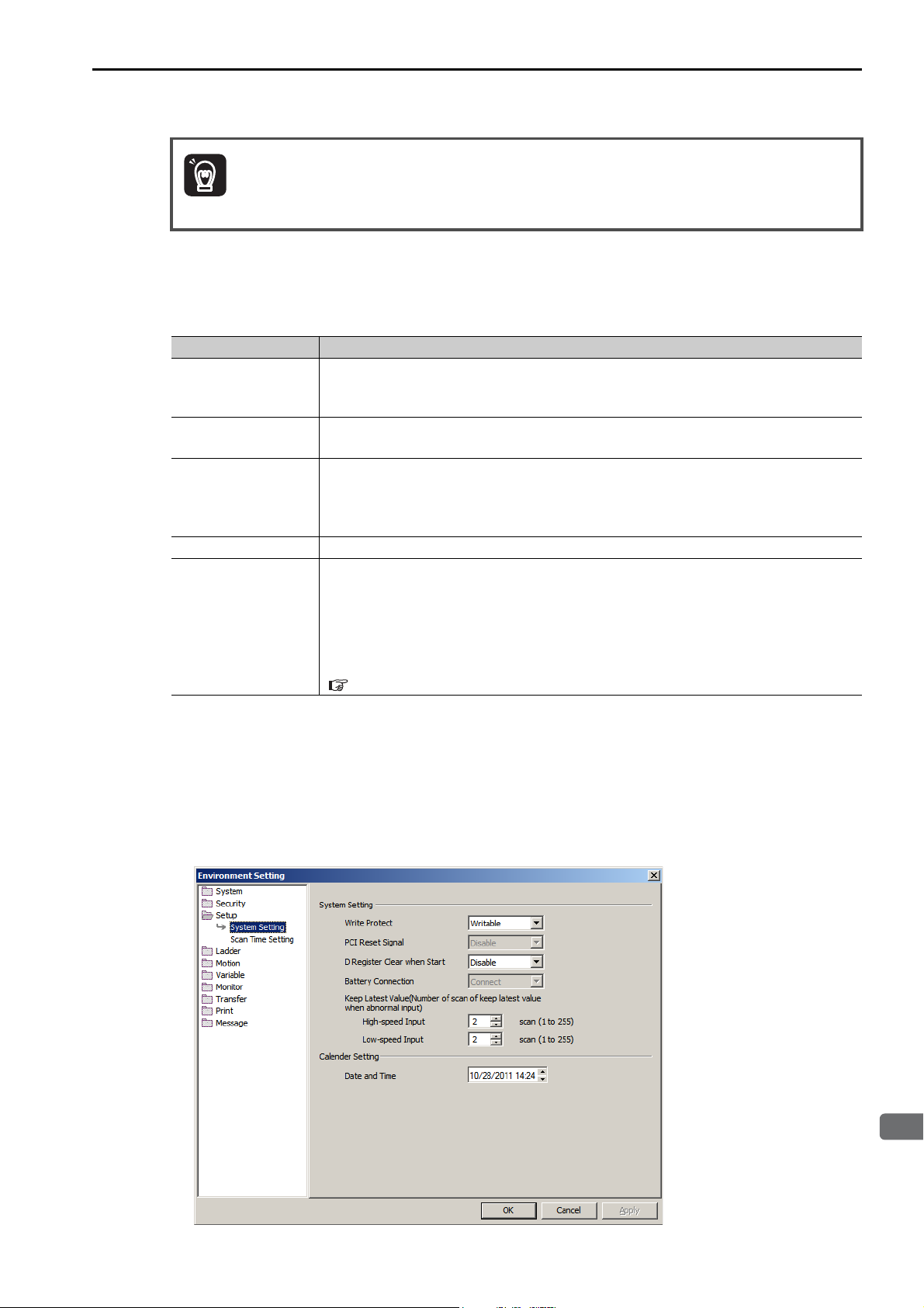
3.1 Basic Functionality
3
CPU Unit Functionality
Important
Registers
User functions can be called from any programs, any number of times.
Precautions When Using Local Registers within a User Function
When you call a user function, consider what values could be in the local registers, and perform initialization as needed.
Name Precautions
X registers (function
input registers)
Y registers (function
output registers)
Z registers (function
internal registers)
# registers These are constant registers. Their values cannot be changed.
D registers
If input values are not set, the values will be uncertain.
Do not use X registers that are outside of the range that is specified in the input defini-
tions.
If output values are not set, the values will be uncertain.
Always set the values of the range of Y registers that is specified in the output definitions.
When the function is called, the previously set values will be lost and the values will be
uncertain.
These registers are not appropriate for instructions if the previous value must be retained.
Use them only after initializing them within the function.
When the function is called, the previously set values are preserved.
If a previous value is not necessary, initialize the value, or use a Z register instead.
D registers retain the data until the power is turned OFF.
The default value after startup depends on the setting of the D Register Clear when
Start option.
Refer to the following sections for details.
Setting the D Register Clear When Start Option (page 3-23)
• Setting the D Register Clear When Start Option
1. Select File − Environment Setting from the MPE720 Version 7 Window.
2. Select Setup − System Setting.
3. Select Enable or Disable for the D Register Clear when Start option.
Disable: The initial values will be uncertain.
Enable: The initial values will be 0.
3-23
Page 74
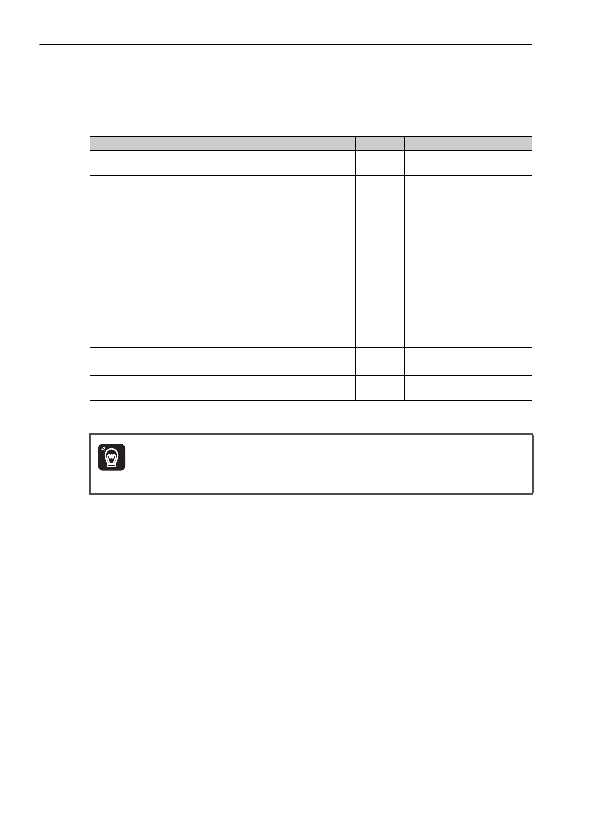
3.1 Basic Functionality
Important
Registers
Data Types
There are various data types that you can use depending on the purpose of the application: bit, integer,
double-length integer, quadruple-length integer, real number, double-precision real number, and address.
Symbol Data Type Range of Values Data Size Description
B Bit 1 (ON) or 0 (OFF) −
W Integer
L
Q
F Real number
D
A Address 0 to 2,097,152 −
*1. These data types cannot be used for indirect designation of motion programs.
*2. Conforms to IEEE754 standards.
Double-length
integer
Quadruple-length
*1
integer
Double-precision
real number
*1
-32,768 to 32,767
(8000 to 7FFF hex)
-2,147,483,648 to 2,147,483,647
(80000000 to 7FFFFFFF hex)
1 word
2 words
-9,223,372,036,854,775,808 to
9,223,372,036,854,775,807
(8000000000000000 to
4 words
7FFFFFFFFFFFFFFF hex)
± (1.175E - 38
to 3.402E + 38) or 0
2 words
± (2.225E - 308 to 1.798E + 308) or 0 4 words
Used in relay circuits and to
determine ON/OFF status.
Used for numeric operations.
The values in parentheses on
the left are for logical operations.
Used for numeric operations.
The values in parentheses on
the left are for logical operations.
Used for numeric operations.
The values in parentheses on
the left are for logical operations.
Used for advanced numeric
operations.
*2
Used for advanced numeric
operations.
*2
Used only as pointers for
addressing.
The MP3000-series Machine Controller does not have separate registers for each data type. As shown
in the following figure, the same address will access the same register even if the data type is different.
For example, MB00001003, a bit address, and the MW0000100, an integer address, have different data
types, but they both access the same register, MW0000100.
3-24
Page 75
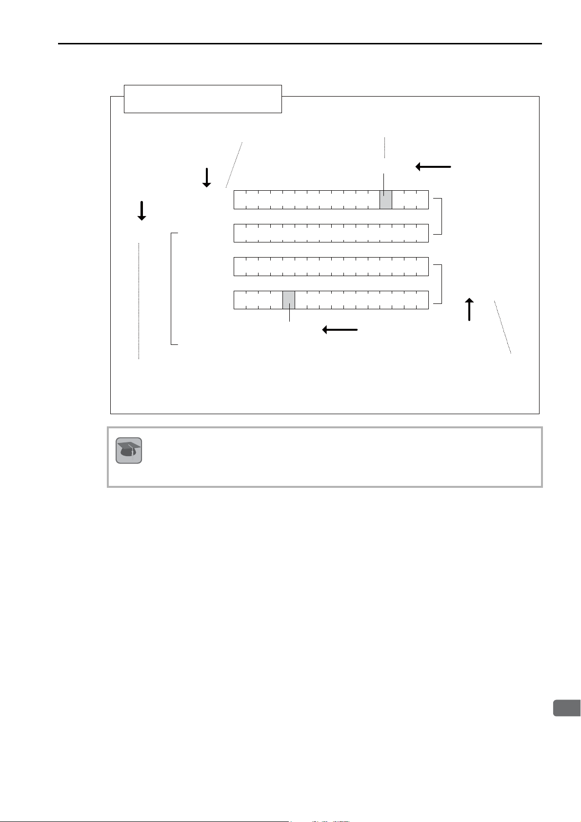
3
CPU Unit Functionality
Data Types and Register Designations
Terms
3.1 Basic Functionality
Registers
One word is allocated for
each register address.
Integer data type
Address data type
[MA0000101]
If MA0000101 is specified as a pointer, it addresses a
continuous data area with the specified register
address (0000101) as the starting address. This data
area can be used with all data types in internal
processing for functions.
[MW0000100]
[MW0000101]
[MW0000102]
[MW0000103]
……
[MB0000103B]
An extra digit that specifies the bit (3) is appended
to the end of the register address (0000100).
[MB00001003]
0123456789ABCDEF
Bit data type
The addressed register (0000102) and the
following register (0000103) are combined
as a 2-word area. Therefore the register
addresses are specified at intervals of 2.
Bit data type
[ML0000100]
[MF0000100]
[ML0000102]
[MF0000102]
Double-length
integer or real
number data type
Pointer Designation
When an address is passed to a function as a parameter, this is referred to as pointer designation. When
pointer designation is used, the continuous data area starting from the address of the specified register
address can be used in internal processing for functions with all data types.
3-25
Page 76
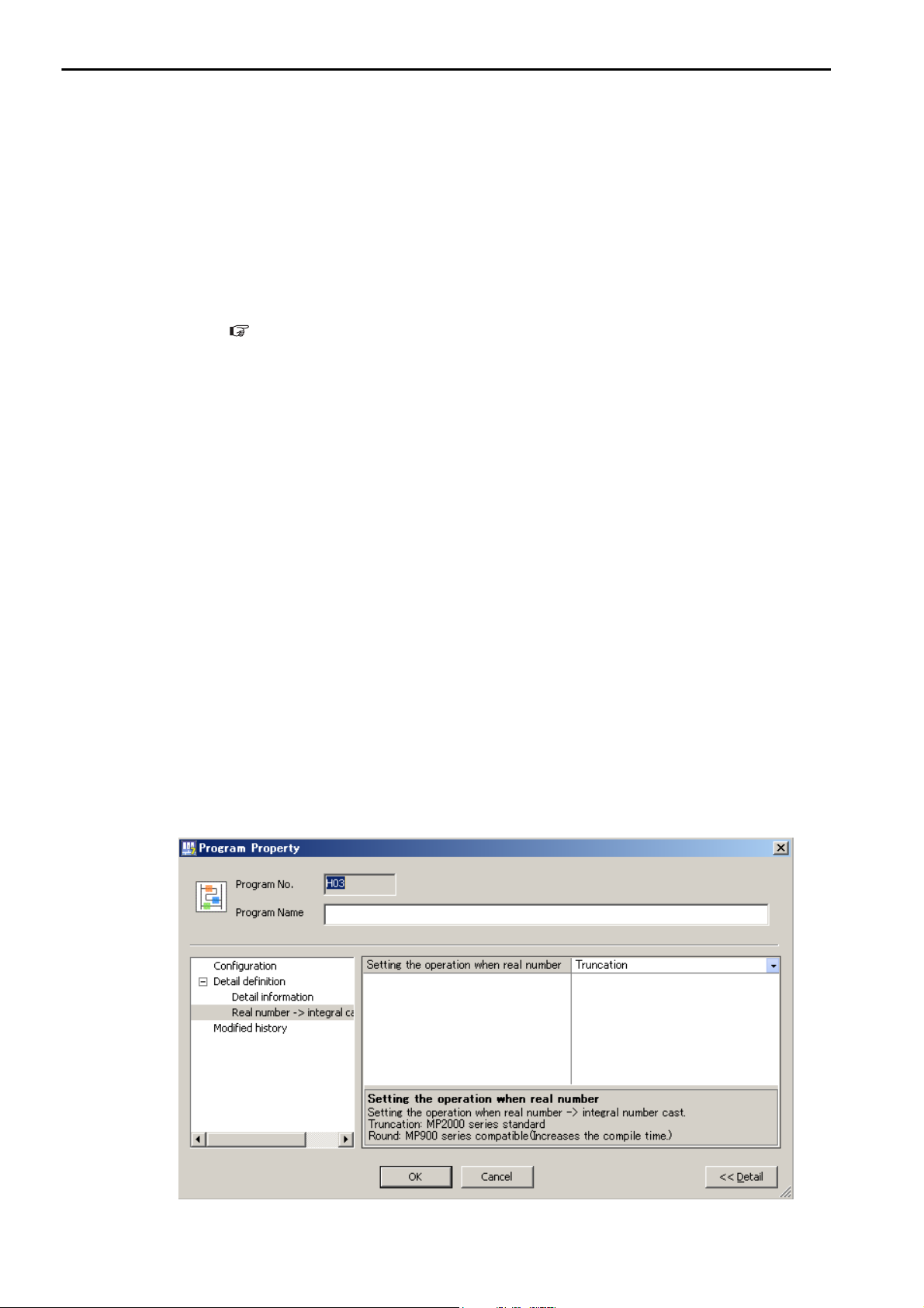
3.1 Basic Functionality
Registers
Precautions for Operations Using Different Data Types
If you perform an operation using different data types, be aware that the results will be different depending
on the data type of the storage register, as described below.
• Storing Real Number Data in an Integer Register
MW0000100 = MF0000200; the real number is stored after it is converted to an integer.
(00001) (1.234)
Note: There may be rounding error due to storing a real number in an integer register.
MW0000100 = MF0000200 + MF0000202
(0124) (123.48) (0.02) The result of the operation may be different depending on the value
(0123) (123.49) (0.01)
• Storing Real Number Data in a Double-length Integer Register
ML0000100 = MF0000200; the real number is stored after it is converted to an integer.
(65432) (65432.1)
• Storing Double-length Integer Data in an Integer Register
MW0000100 = ML0000200; the lower 16 bits of the double-length integer are stored without change.
-
00001) (65535)
(
Whether numbers are rounded or truncated when converting a real number to an integer can be set in the
properties of the drawing.
Setting for Real Number Casting (page 3-26)
of the variable.
• Storing Integer Data in a Double-length Integer Register
ML0000100 = MW0000200; the integer is stored after it is converted to double-length integer data.
(0001234) (1234)
Setting for Real Number Casting
The casting method (truncating or rounding) can be set in the detailed definitions in the Drawing Properties Dialog Box. The method to use for real number casting is set for each drawing.
Use the following procedure to display the Program Property Dialog Box.
1. In the Ladder Pane, select the ladder program for which to view the properties.
2. Right-click the selected program and select Property from the pop-up menu.
The Program Property Dialog Box will be displayed.
3-26
Page 77
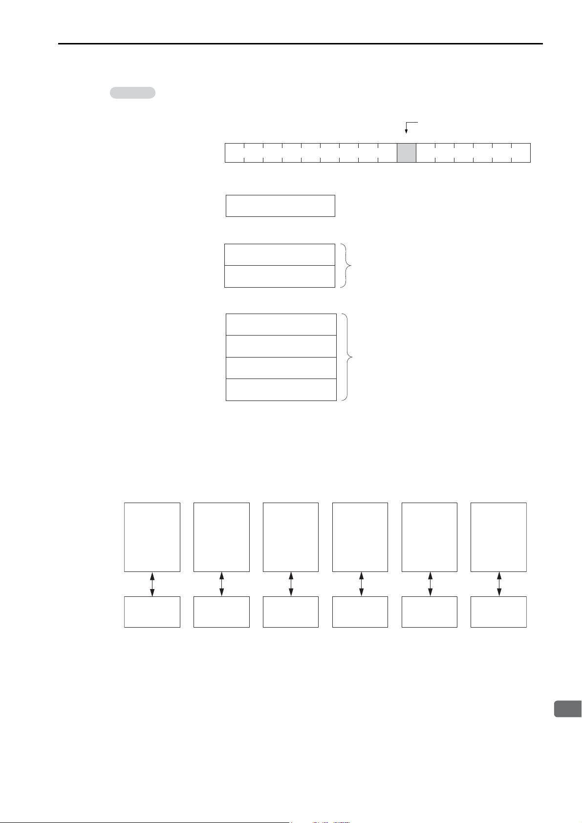
3
CPU Unit Functionality
The data is little endian, as shown in the following example.
Information
MW0000100 1234 hex
DWG.H DWG.LDWG.A DWG.I
Motion
program*
Sequence
program*
i and j registers i and j registers i and j registers i and j registers i and j registers i and j registers
• MB00001006
FEDCBA9876543210Bit
MW0000100
• MW0000100 = 1234 hex
• ML0000100 = 12345678 hex
3.1 Basic Functionality
Registers
MB00001006
MW0000100
MW0000101
5678 hex
ML0000100
1234 hex
• MQ0000100 = 123456789ABCDEF0 hex
MW0000100
MW0000101
MW0000102
MW0000103
DEF0 hex
9ABC hex
MQ0000100
5678 hex
1234 hex
Index Registers (i, j)
There are two special registers, i and j, that are used to modify relay and register addresses. The functions
of i and j are identical. They are used to handle register addresses like variables.
There are subscript registers for each program type, as shown in the following figure.
* Motion programs and sequence programs have separate i and j registers for each task.
Note: Functions reference the i and j registers that belong to the calling drawing.
For example, a function called by DWG.H will reference the i and j registers for DWG.H.
We will describe this with examples for each register data type.
3-27
Page 78
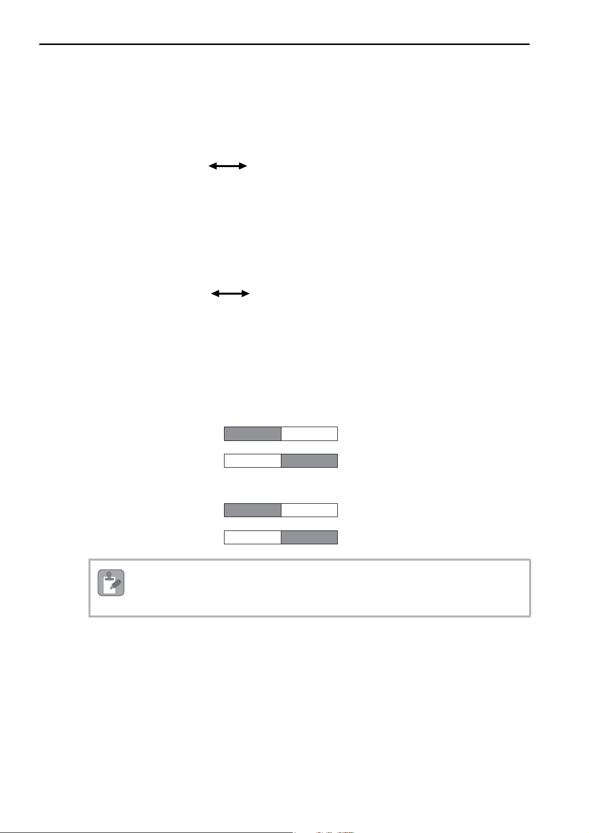
3.1 Basic Functionality
i = 2;
DB000000 = MB00000000i; DB000000 = MB00000002;
Equivalent
DW00000 = MW0000031;DW00000 = MW0000001j;
j = 30;
Equivalent
If j = 0, ML0000000j is ML0000000.
If j = 1, ML0000000j is ML0000001.
Double-length Integer Upper Word
MW0000001
Lower Word
MW0000000
If j = 0, MF0000000j is MF0000000.
If j = 1, MF0000000j is MF0000001.
Real Number
Upper Word
MW0000001
Lower Word
MW0000000
MW0000002 MW0000001
MW0000002 MW0000001
Note
Registers
Attaching an Index to a Bit Register
Using an index is the same as adding the value of i or j to the register address.
For example, if i = 2, MB00000000i is the same as MB00000002.
Attaching an Index to an Integer Register
Using an index is the same as adding the value of i or j to the register address.
For example, if j = 30, MW0000001j is the same as MW0000031.
Attaching an Index to a Double-length Integer or a Real Number Register
Using an index is the same as adding the value of i or j to the register address.
For example, if j = 1, ML0000000j is the same as ML0000001. Similarly, if j = 1, MF0000000j is the same
as MF0000001.
Double-length integers and real numbers use a region that is 2 words in size. For example, when using
ML0000000j with both j = 0 and j = 1, the one-word area of MW0000001 will overlap. Be careful of
overlapping areas when indexing double-length integer or real number register addresses.
3-28
Page 79
3.1 Basic Functionality
3
CPU Unit Functionality
If j = 0, MQ0000000j is MQ0000000.
If j = 2, MQ0000000j is MQ0000002.
Quadruple-length Integer Upper 2 words
Lower 2 words
Upper 2 words Lower 2 words
If j = 0, MD0000000j is MD0000000.
If j = 2, MD0000000j is MD0000002.
Double-precision Real Number
Upper 2 words Lower 2 words
Upper 2 words Lower 2 words
MW0000003 MW0000002
MW0000005
MW0000004
MW0000001 MW0000000
MW0000003 MW0000002
MW0000003 MW0000002
MW0000005
MW0000004
MW0000001 MW0000000
MW0000003 MW0000002
Note
Registers
Attaching an Index to a Quadruple-length Integer or a Double-precision
Real Number Register
Using an index is the same as adding the value of i or j to the register address.
For example, if j = 2, MQ0000000j is the same as MQ0000002. Similarly, if j = 2, MD0000000j is the
same as MD0000002.
Quadruple-length integers and double-precision real numbers use a region that is 4 words in size. For
example, when using MQ0000000j with both j = 0 and j = 2, the two-word area of MW0000002 and
MW0000003 will overlap. Be careful of overlapping areas when indexing quadruple-length integer or
double-precision real number register addresses.
3-29
Page 80

3.1 Basic Functionality
DW00000 = 2;
DB000020 = MB00000000[DW00000]; DB000020 = MB00000002;
Equivalent
DW00000 = 30;
DL00002 = ML0000002[DW00000]; DL00002 = ML0000062;
Equivalent
Registers
Array Registers ([ ])
Array registers are used to modify register addresses, and are denoted by square brackets [ ].
These are used to handle register addresses like variables.
Similarly to index registers, an offset is added to the register address.
Attaching an Array Register to a Bit Register
Using an array register is the same as adding the value of the array register to the register address.
For example, if DW00000 = 2, MB00000000[DW00000] is the same as MB00000002.
Attaching an Array Register to a Register Other Than a Bit Register
Using an array register is the same as adding the word size of the data type of the array register times the
value of the array register to the register address.
For example, if DW00000 = 30, ML0000002[DW00000] is the same as ML0000062.
DL00002 = ML00000 (30 × 2 + 2) = ML0000062
3-30
Page 81
3
CPU Unit Functionality
Execution Scheduling
Power ON
DWG.A
(Startup Drawings)
Interrupt signal
DWG.I
(interrupt drawing)
Execution is continued
from the point before
the interrupt.
Every low-speed scan
Batch output
Batch input
DWG.L (low-speed
scan process drawing)
Every high-speed scan
Batch output
Batch input
DWG.H (high-speed
scan process drawing)
*1
*2
Low-speed scan time
High-speed
scan time
High-speed
scan time
High-speed
scan time
High-speed
scan time
DWG.H
(high-speed
scan process
drawing)
DWG.L
(low-speed
scan process
drawing)
Background
processing*
: Actual processing time during the scan
This section describes the execution order of drawings.
Controlling the Execution of Drawings
Drawings are executed based on their priorities, as shown in the following figure.
3.1 Basic Functionality
Execution Scheduling
*1. DWG.A drawings are executed immediately after the power supply is turned ON.
*2. When an interrupt signal is input, execution of the DWG.I drawing is given priority even if execution of a DWG.H or
DWG.L drawing is currently in progress.
Note: The parent drawing of each drawing is automatically called and executed by the system.
Scheduling the Execution of High-speed and Low-speed Scan Process Drawings
High-speed scan process drawings (DWG.H) and low-speed scan process drawings (DWG.L) cannot be
executed at the same time. DWG.L drawings are executed during the idle time of DWG.H drawings.
The period during which DWG.H drawings are executed is called the high-speed scan time. The period
during which DWG.L drawings are executed is called the low-speed scan time.
* Background processing is used to execute internal system processing, such as communications processing.
Refer to the following section for the setting procedure for the high-speed and low-speed scans.
Setting the High-speed and Low-speed Scan Times (page 3-34)
3-31
Page 82
3.1 Basic Functionality
Note
Information
Scans
Scans
A scan refers to the processing that starts at fixed intervals.
This section describes the scans.
Types of Scans
The CPU Unit has two types of scans, the high-speed H scan and low-speed L scan.
A high-speed H scan has higher priority than a low-speed L scan. The fixed period for each scan, also
known as the scan time, can be set by the user.
This section describes the settings for the scan times.
High-speed (H) Scan
The following table shows the different high-speed scan time set values depending on whether the
MP2000 Optional Module is used.
There are restrictions on the set value of the high-speed scan time. Refer to the following section for
details.
High-speed Scan Time Set Value Restrictions (page 3-32)
When the MP2000 Optional Module Is Not Used When the MP2000 Optional Module Is Used
0.125 to 32.0 ms (in 0.125-ms increments)
The default high-speed scan time is 4.0 ms.
0.125 ms, 0.250 ms, or 0.5 to 32.0 ms (in 0.5-ms increments)
High-speed Scan Time Set Value Restrictions
This section describes the restrictions on the set value of the high-speed scan time.
Restrictions Imposed by the MECHATROLINK-III Communications Cycle
The high-speed scan of the CPU Unit is synchronized with the MECHATROLINK-III communications
cycle of the SVC32 Module built into the CPU Unit. This imposes the following restrictions in the set
value of the high-speed scan time.
Communica-
tions Cycle
125 μs Integral multiple of 125 μs
250 μs
500 μs
1 ms
1.5 ms
High-speed Scan Time Set
Value Restrictions
Integral multiple of 250 μs or
1 times the integer portion
Integral multiple of 500 μs or
1 times the integer portion
Integral multiple of 1 ms or 1
times the integer portion
Integral multiple of 1.5 ms or
1 times the integer portion
When MP2000 Optional
Module Is Not Used
0.125 to 32.0 ms (in increments of 0.125 ms)
0.250 to 32.0 ms (in increments of 0.250 ms)
0.5 to 32.0 ms (in increments
of 0.5 ms)
1.0 to 32.0 ms (in increments
of 1 ms)
1.5 to 31.5 ms (in increments
of 1.5 ms)
Possible Set Values
When MP2000 Optional
Module Is Used
0.125 ms, 0.250 ms, or 0.5 to
32.0 ms (in increments of 0.5
ms)
0.250 ms or 0.5 to 32.0 ms (in
increments of 0.5 ms)
0.5 to 32.0 ms (in increments
of 0.5 ms)
1.0 to 32.0 ms (in increments
of 1 ms)
1.5 to 31.5 ms (in increments
of 1.5 ms)
Continued on next page.
3-32
Page 83
3.1 Basic Functionality
3
CPU Unit Functionality
0.5 ms
c
c
c
d
d
d
e
e
e
High-speed scan
MP2000
Optional Module
System service
register SB000008*
Basic cycle
(0.5 ms)
Reference issued at c Reference issued at d Reference issued at e
Scans
Continued from previous page.
Communica-
tions Cycle
2 ms
3 ms
High-speed Scan Time Set
Value Restrictions
Integral multiple of 2 ms or 1
times the integer portion
Integral multiple of 3 ms or 1
times the integer portion
When MP2000 Optional
Module Is Not Used
2.0 to 32.0 ms (in increments
of 2 ms)
3.0 to 30.0 ms (in increments
of 3 ms)
Possible Set Values
When MP2000 Optional
Module Is Used
2.0 to 32.0 ms (in increments
of 2 ms)
3.0 to 30.0 ms (in increments
of 3 ms)
If these restrictions are not observed, the high-speed scan cycle will stop and an alarm will occur. The
alarm is reported in the M-III Restrictions Error Bit (SB00041D) in the CPU Error Status System Register.
Refer to the following section for details.
4.3 CPU Unit Specifications − System Status (page 4-19)
Restrictions Imposed by Σ-V SERVOPACKs
The specifications of MECHATROLINK-III Σ-V-series SERVOPACKs impose the following restrictions
on the set value of the high-speed scan time.
Σ-V SERVOPACK
Versio n
Restrictions
High-speed scan time set value ≤ (32 × Communications cycle)
Lower than version 21
Example: If the MECHATROLINK-III communications cycle is 125 μs, the set value of
the high-speed scan time can be up to 4.0 ms (125 μs × 32).
High-speed scan time set value ≤ (254 × Communications cycle)
Version 21 or higher
Example: If the MECHATROLINK-III communications cycle is 125 μs, the set value of
the high-speed scan time can be up to 31.75 ms (125 μs × 254).
If these restrictions are not observed, an A.94B Data Setting Warning 2 (Data Out of Range) warning will
occur in the SERVOPACK.
I/O Processing
If the high-speed scan time is set to at least 0.5 ms, the I/O service (I/O processing) of the MP2000
Optional Module will be performed every scan.
If the high-speed scan time is set to less than 0.5 ms (0.125 ms or 0.250 ms), the I/O service (I/O processing) of the MP2000 Optional Module will be performed at the filtered basic cycle of 0.5 ms.
The following figures show the timing results for these settings.
Example: High-speed Scan Time Set to 0.5 ms
* The purpose of this system service register is to determine from a ladder program whether the I/O scan service
is being executed for MP2000 Optional Modules
3-33
Page 84
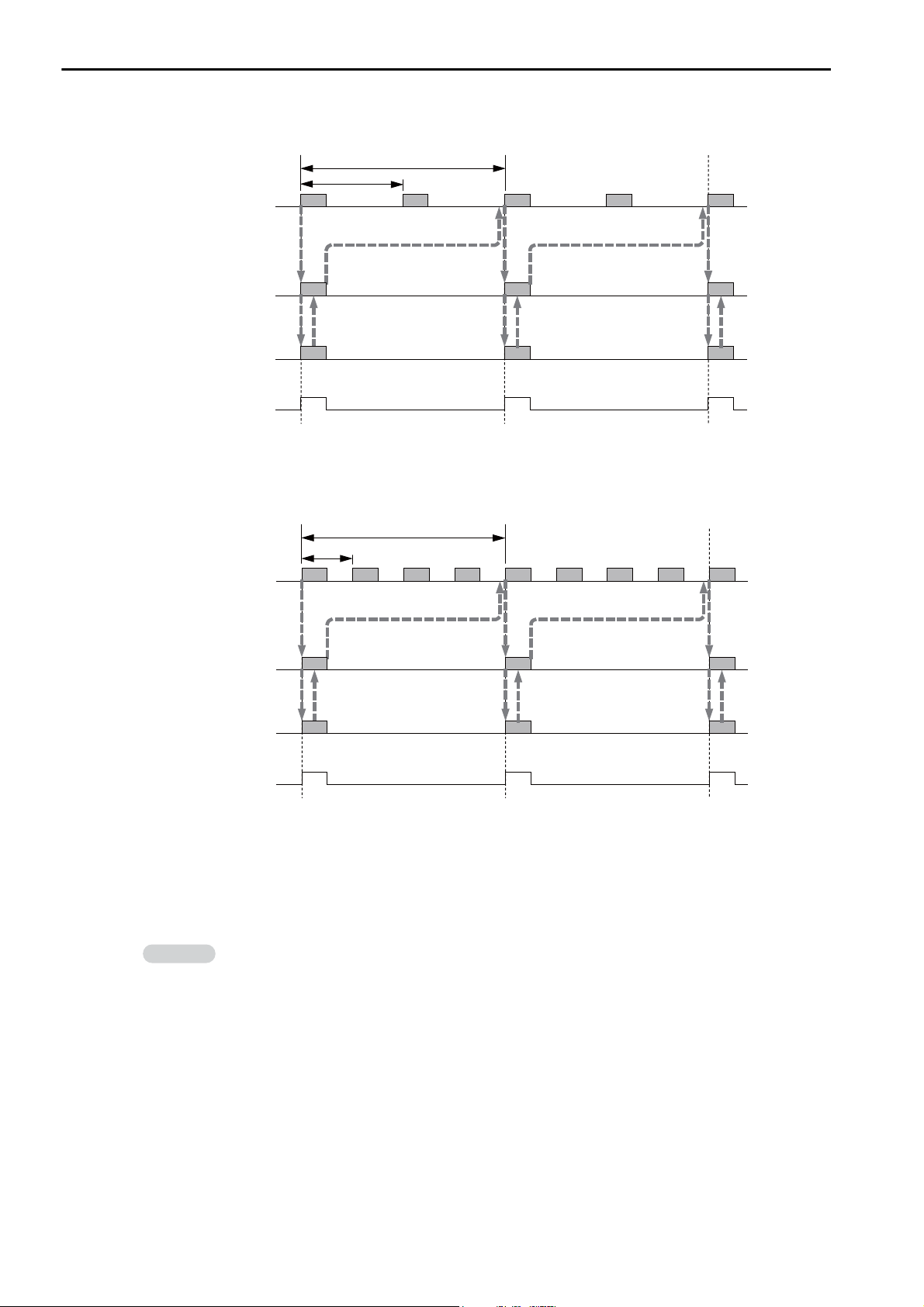
3.1 Basic Functionality
0.25 ms
0.5 ms
c
c
c
d
e
e
f
g
e
g
g
High-speed scan
Basic cycle
(0.5 ms)
Reference issued at c
MP2000
Optional Module
System service
register SB000008*
Reference issued at e
Reference
issued at g
0.125 ms
0.5 ms
c
c
c
d
e
f
g
g
h
i
j
k
k
k
g
High-speed scan
Basic cycle
(0.5 ms)
MP2000
Optional Module
System service
register SB000008*
Reference issued at c Reference issued at g
Reference
issued at k
Information
Scans
Example: High-speed Scan Time Set to 0.250 ms
* The purpose of this system service register is to determine from a ladder program whether the I/O scan service
Example: High-speed Scan Time Set to 0.125 ms
is being executed for MP2000 Optional Modules
3-34
* The purpose of this system service register is to determine from a ladder program whether the I/O scan service
is being executed for MP2000 Optional Modules
Low-speed (L) Scan
The setting range for the low-speed scan time is 2.0 to 300.0 ms (in increments of 0.5 ms).
The default low-speed scan time is 200.0 ms.
I/O Processing
During the low-speed scan, the I/O service (I/O processing) is performed every scan, regardless of the set
value.
Setting the High-speed and Low-speed Scan Times
Use MPE720 version 7 and perform the procedure given below to set the high-speed and low-speed scan
times.
1.
Stop the CPU Unit.
Page 85
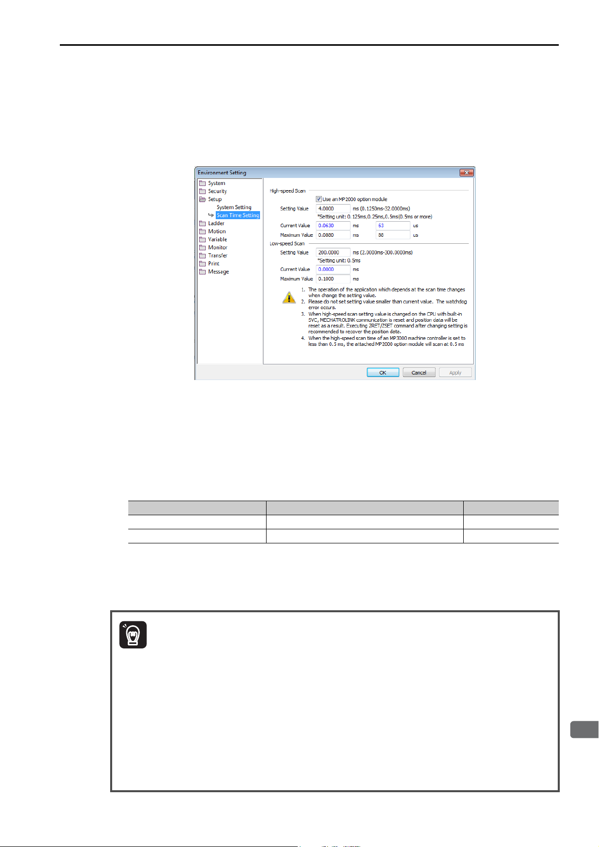
3.1 Basic Functionality
3
CPU Unit Functionality
Important
Scans
2. Select File
−
Environment Setting from the menu bar. Alternatively, click the System Setting
Icon on the Start Tab Page.
The Environment Setting Dialog Box will be displayed.
3. Select Setup
−
Scan Time Setting.
The following dialog box will be displayed.
Setting Value: Enter the scan time settings.
Current Value: A value of 0.0 ms is displayed when the MPE720 is offline. Otherwise, the actual pro-
cessing times for the scans are displayed.
Maximum Value: The maximum processing time for the scan is displayed. You can set the maximum
value. The setting is retained until it is exceeded.
4. Enter the high-speed scan time in the Setting Value Box under High-speed Scan. Enter the low-
speed scan time in the Setting Value Box under Low-speed Scan.
The following table shows the possible set values and default values for each scan time.
Item Possible Set Values Default
High-speed Scan Time 0.125 to 32 ms (in 0.125-ms increments) 4.0 ms
Low-speed Scan Time 2.0 to 300.0 ms (in 0.5-ms increments) 200.0 ms
Note: The possible set values and default values depend on the model. Refer to the user’s manual for the Module
you are using for details.
5. Click the OK Button.
The settings will be saved and the Environment Setting Dialog Box will close.
Observe the following precautions when setting the high-speed scan time and low-speed
scan time.
1. Set the scan set value so that it is 1.25 times greater than the maximum value.
If the scan set value is too close to the maximum value, the refresh rate of the MPE720 window will
noticeably drop and can cause communications timeout errors to occur. If the maximum value
exceeds the scan set value, a watchdog error may occur and cause the Machine Controller system to
shut down.
2. If you are using MECHATROLINK-II or MECHATROLINK-III, set values that are an integral
multiple of the communications cycle. If you change the communications cycle, check the scan time
set values.
3. Do not change the scan set value while the Servo is ON. Never change the scan set value while an
axis is in motion (i.e., while the motor is rotating). Doing so may cause the motor to rotate out of
control.
4. After changing or setting a scan time, always save the data to flash memory.
3-35
Page 86
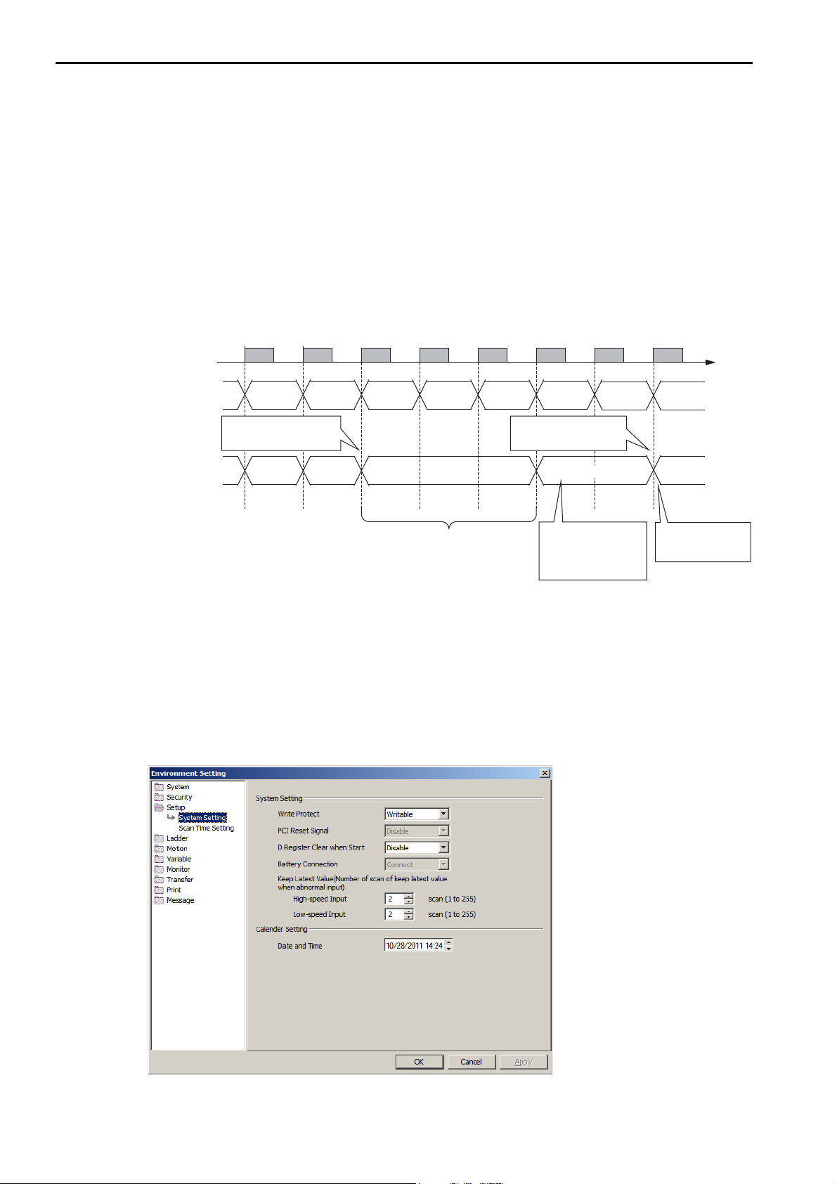
3.1 Basic Functionality
Scans
Keep Latest Value Setting in High-speed/Low-speed Scans
You can use the Keep Latest Value setting to specify the number of scans to hold previous data when an
input error occurs. If the input error still exists after the number of scans specified for the Keep Latest
Value setting, the input values will be treated as 0. When the input error is removed, reading the input values is resumed automatically. There are separate Keep Latest Value settings for the high-speed scan and
the low-speed scan.
Operation
The following figure illustrates the operation for the Keep Latest Value setting.
Keep Latest Value setting: 3 scans for high-speed scan
High-speed scan
Input value
to I/O
Module 1
Input value
to I/O
Module 2
100 101 102 103 104 105
Input error occurred in
I/O Module 2.
200 201
201
Input error removed
from I/O Module 2.
0
106 107
207
Keep Latest Value region:
The value from before
the input error (201) is held for 3 scans.
The number of scans
set for the Keep Latest
Value setting was
exceeded, so the input
value is treated as 0.
Reading the input
value is automatically started again.
Setting Procedure
Perform the following procedure with MPE720 version 7 to set the Keep Latest Value setting.
1.
Select File − Environment Setting from the menu bar. Alternatively, click the System Setting
Icon on the Start Tab Page.
The Environment Setting Dialog Box will be displayed.
2. Select Setup
The following dialog box will be displayed.
−
System Setting.
3-36
3. Set values in the High-speed Input and Low-speed Input Boxes in the Keep Latest Value
Group.
Page 87
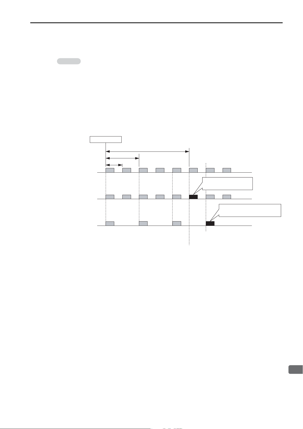
3
CPU Unit Functionality
4. Click the OK Button.
Information
0.250 ms
0.5 ms
Input error
Keep Latest Value setting = 5 scans for high-speed scan
High-speed scan
Function Modules
(218IFD and SVC32)
in the CPU Unit
MP2000
Optional Module
Service scan on MP2000-series Optional Module
immediately after the specified number of scans
Service scan on Function Modules in the CPU Unit
immediately after the specified number of scans
Input registers in the
Function Modules in the
CPU Unit are cleared.
The input registers in the MP2000
Optional Module are cleared.
The settings will be saved and the Environment Setting Dialog Box will close.
The Keep Latest Value setting specifies the number of scans to process before the I/O service
clears the input registers.
If the high-speed scan time setting is set to 0.250 ms or 0.125 ms, the scan at which the input registers are cleared will differ for the MP2000-series Optional Module and the 218IFD and SVC32
Function Modules that are built into the CPU Unit.
In the following example, an input error occurs simultaneously on the MP2000-series Optional
Module and the 218IFD and SVC32 Function Modules in the CPU Unit when the high-speed scan
setting is set to 0.250 ms and the Keep Latest Value setting is set to 5 scans.
The input registers in the 218IFD and SVC32 Function Modules built into the CPU Unit are
cleared on the sixth scan that immediately follows the specified number of scans, whereas on the
MP2000-series Optional Module, the input registers are cleared on the seventh service scan that
immediately follows the specified number of scans.
3.1 Basic Functionality
Scans
3-37
Page 88
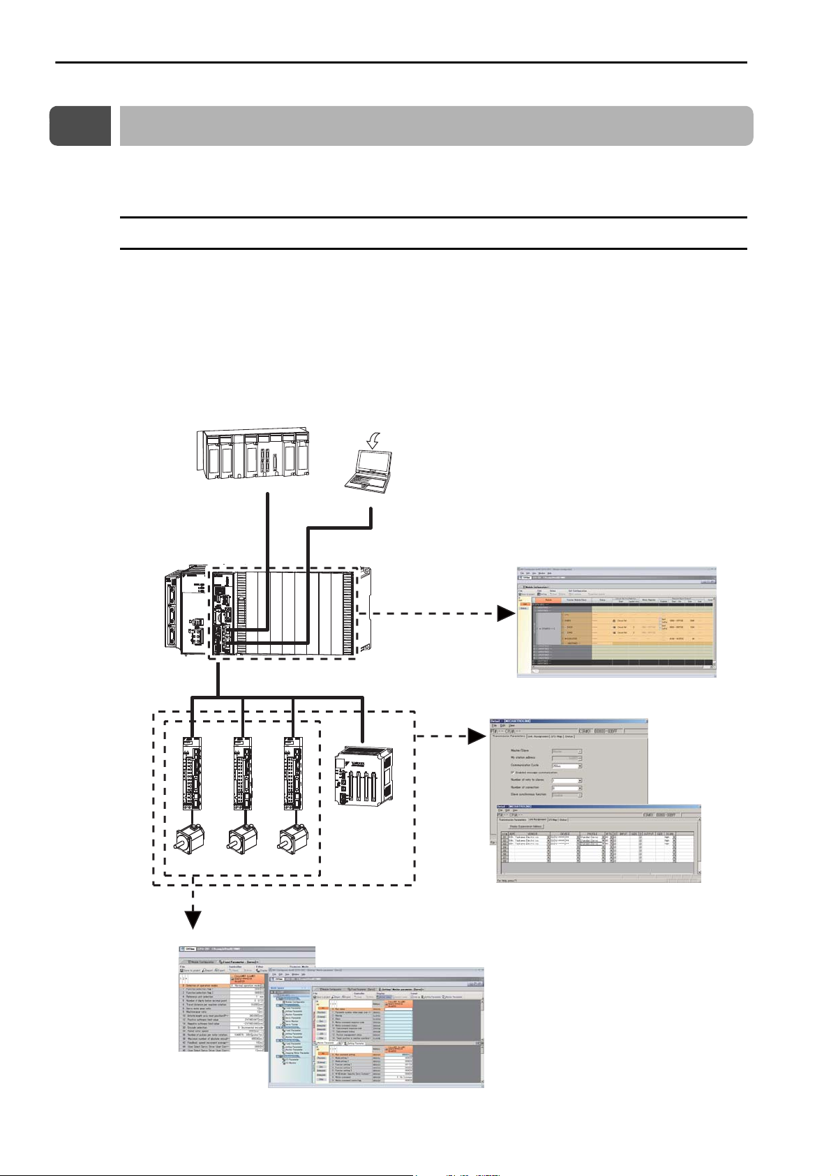
3.2 Function Modules
Self Configuration
3.2
Function Modules
This section describes the Function Modules that are built into the CPU Unit.
Self Configuration
Self configuration is a feature that automatically recognizes all the Optional Modules that are installed in
the Machine Controller and all the slave devices that are connected via the MECHATROLINK connector
(such as Servo Drives), and creates the module configuration definition files based on that information.
Self configuration greatly reduces the steps that are required to set up the system. Use the DIP switch on
the CPU Unit or use the MPE720 to execute self configuration.
The following figure illustrates self configuration.
Executing Self Configuration
Host PLC
Ethernet
MPE720 Integrated Engineering
Tool Version 7
PC
Ethernet
MECHATROLINK-III
Servomotor Servomotor Servomotor
Detection of motion parameter information
(SERVOPACKs)
Automatically writing the SVC definitions
Detection of information from
the Function Modules in the
CPU Unit (218IFD, SVC32,
SVR32, and M-EXECUTOR)
and from Optional Modules
Detection of slave
device information
I/O
Automatically writing the Module
configuration definitions
Automatically writing the MECHATROLINK
communications definitions
3-38
Page 89
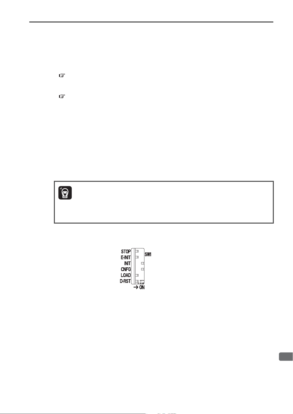
3.2 Function Modules
3
CPU Unit Functionality
Important
Self Configuration
Operating Procedures
This section describes the procedures for executing self configuration.
• Refer to the following section when you perform self configuration for the first time after connecting the
devices.
Self Configuration Using the DIP Switch (page 3-39)
• If the Machine Controller and the MPE720 are already connected, the self configuration can be performed by using the MPE720.
Self Configuration Using the MPE720 (page 3-42)
Self Configuration Using the DIP Switch
The procedure for executing self configuration using the DIP switch depends on whether self configuration is being done for the first time since the devices were connected, or if SERVOPACKs or other devices
have been added.
Both procedures are described below.
First Self Configuration after Connecting the Devices
The following procedure performs a new self configuration of all Modules, and creates new definition
files.
1. Before performing this procedure, turn ON the power supply to the SERVOPACKs and other
devices.
2. This procedure will clear the following data:
• All definition files
• All user programs
• All registers
1. Turn OFF the power supply to the CPU Unit.
2. Turn ON only the INIT and CNFG pins on the SW1 DIP switch on the CPU Unit.
3. Turn ON the power supply to the CPU Unit.
Self configuration will be executed.
4. Confirm that the status indicators on the CPU Unit change in the following way:
• RDY: Goes out, and then lights.
• RUN: Goes out, flashes, and then lights.
3-39
Page 90
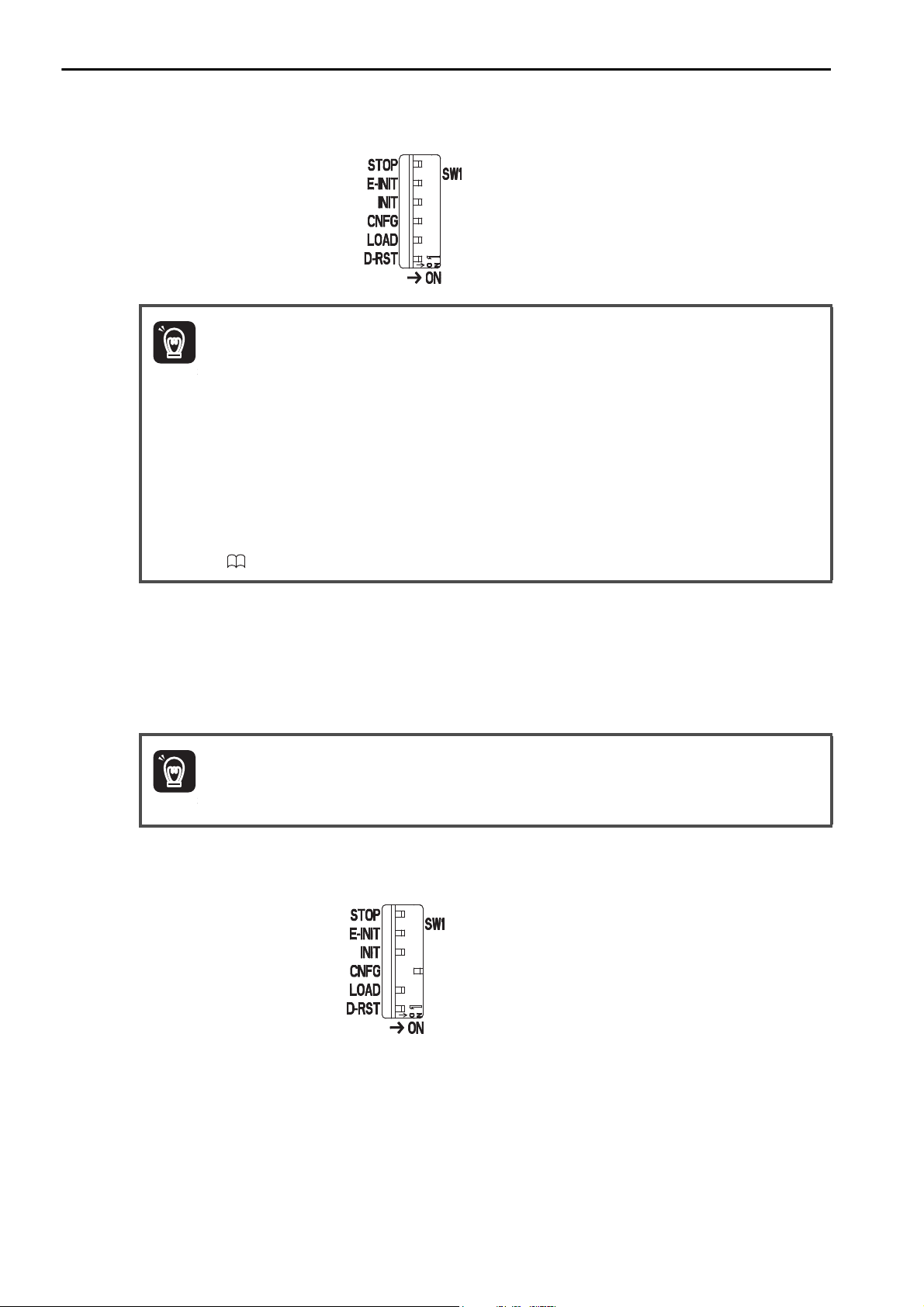
3.2 Function Modules
ImportantImportant
ImportantImportant
Self Configuration
5. Turn OFF the INIT and CNFG pins on the SW1 DIP switch on the CPU Unit.
1. INIT Pin on the DIP Switch and RAM Data
If the power supply is turned OFF and ON again when the INIT pin on the Machine Controller SW1
DIP switch is turned ON, the data in RAM will be cleared.
If the power supply is turned OFF and ON again when the INIT pin is turned OFF, the data from the
flash memory will be loaded and will overwrite the RAM data. Therefore, if the power supply must
be turned OFF while writing or editing a program, make sure you save the data to the Machine Controller’s flash memory to protect the RAM data.
2. Power Interruptions after Self Configuration
After performing self configuration, turn OFF the power supply to the Machine Controller only after
the definition data is saved to the flash memory of the Machine Controller.
If by chance, the power supply is turned OFF before the data is saved, perform self configuration
again.
Refer to the following manual for details on saving data to the flash memory.
MP2000/MP3000 Series Machine Controller System Setup Manual (Manual No.: SIEP C880725 00)
After Adding SERVOPACKs, Optional Modules, and Other Devices
The following procedure will create the definitions for devices and Function Modules that are newly
detected by MECHATROLINK communications. This procedure will not update any of the definitions
that were made for existing devices and Function Modules. The definitions before self configuration will
be retained.
Before performing this procedure, turn ON the power supply to the SERVOPACKs and other devices.
1. Turn OFF the power supply to the CPU Unit.
2. Turn ON only the CNFG pin on the SW1 DIP switch on the CPU Unit.
3. Turn ON the power supply to the CPU Unit.
Self configuration will be executed.
3-40
Page 91
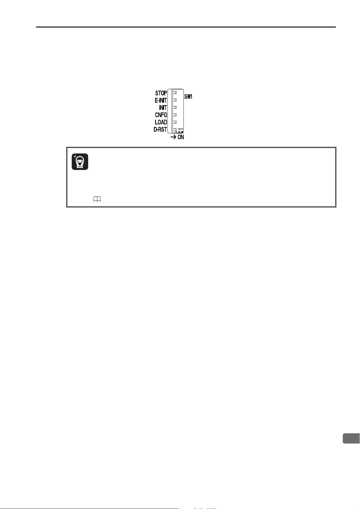
3.2 Function Modules
3
CPU Unit Functionality
ImportantImportant
4. Confirm that the status indicators on the CPU Unit change in the following way:
• RDY: Goes out, and then lights.
• RUN: Goes out, flashes, and then lights.
5. Turn OFF the CNFG pin on the SW1 DIP switch on the CPU Unit.
Power Interruptions after Self Configuration
After performing self configuration, turn OFF the power supply to the Machine Controller only after
the definition data is saved to the flash memory of the Machine Controller.
If by chance, the power supply is turned OFF before the data is saved, perform self configuration
again.
Refer to the following manual for details on saving data to the flash memory.
MP2000/MP3000 Series Machine Controller System Setup Manual (Manual No.: SIEP C880725 00)
Self Configuration
3-41
Page 92
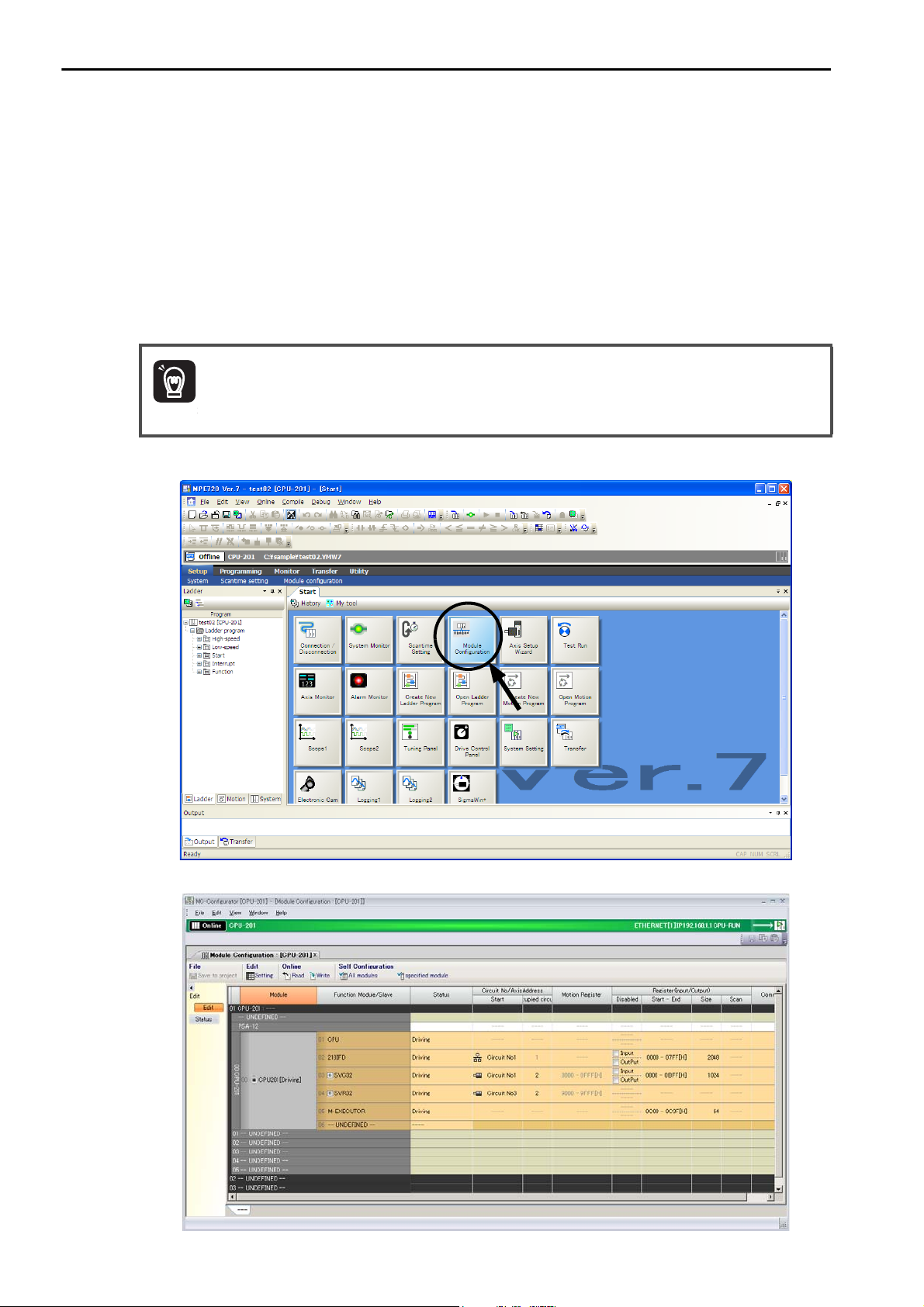
3.2 Function Modules
ImportantImportant
Self Configuration
Self Configuration Using the MPE720
There are two types of self configuration that can be performed with the MPE720.
• Self configuration of all Modules: Use this mode when the system is being set up for the first time, or
after the entire system has been changed.
• Self configuration of specified Modules: Use this mode when a part of the system has been changed.
This process will automatically recognize all devices that have been added or removed, and automatically generate definition files for them.
Self Configuration of All Modules
Click the Module Configuration Icon on the Start Tab Page.
1.
Before performing this procedure, turn ON the power supply to the SERVOPACKs and other devices.
3-42
The following Module Configuration Definition Tab Page will be displayed.
Page 93
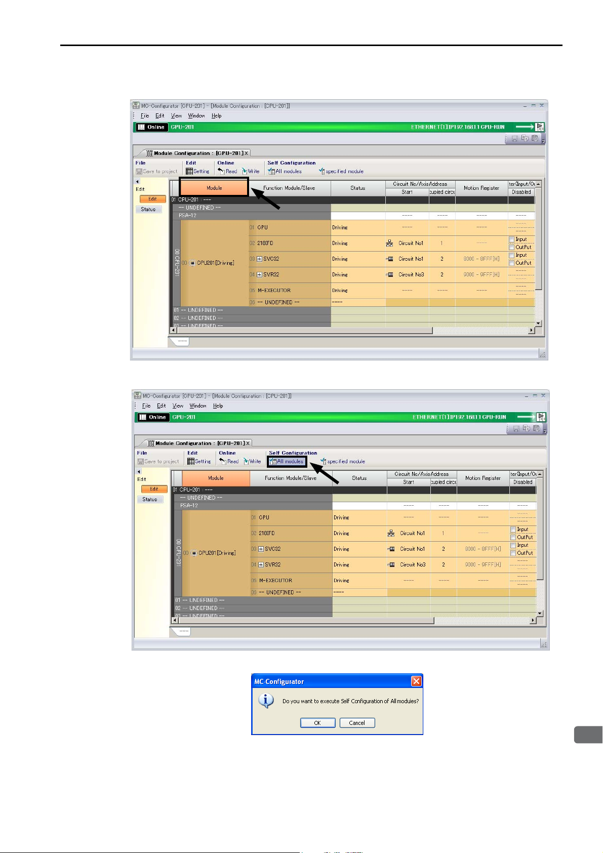
3
CPU Unit Functionality
2. Click the Module Button.
3.2 Function Modules
Self Configuration
3. Click the All modules Button on the Launcher.
The MC-Configurator Dialog Box will be displayed.
4. Click the OK Button.
Self configuration will be executed.
3-43
Page 94
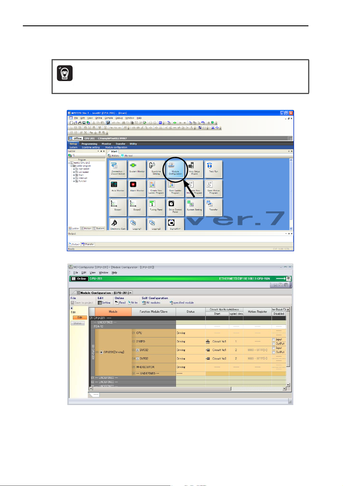
3.2 Function Modules
ImportantImportant
Self Configuration
Self Configuration of Specified Modules
Click the Module Configuration Icon on the Start Tab Page.
1.
Before performing this procedure, turn ON the power supply to the SERVOPACKs and other devices.
The following Module Configuration Definition Tab Page will be displayed.
2. In the Function Module/Slave Column, select the Modules to configure using self configuration.
3-44
Page 95
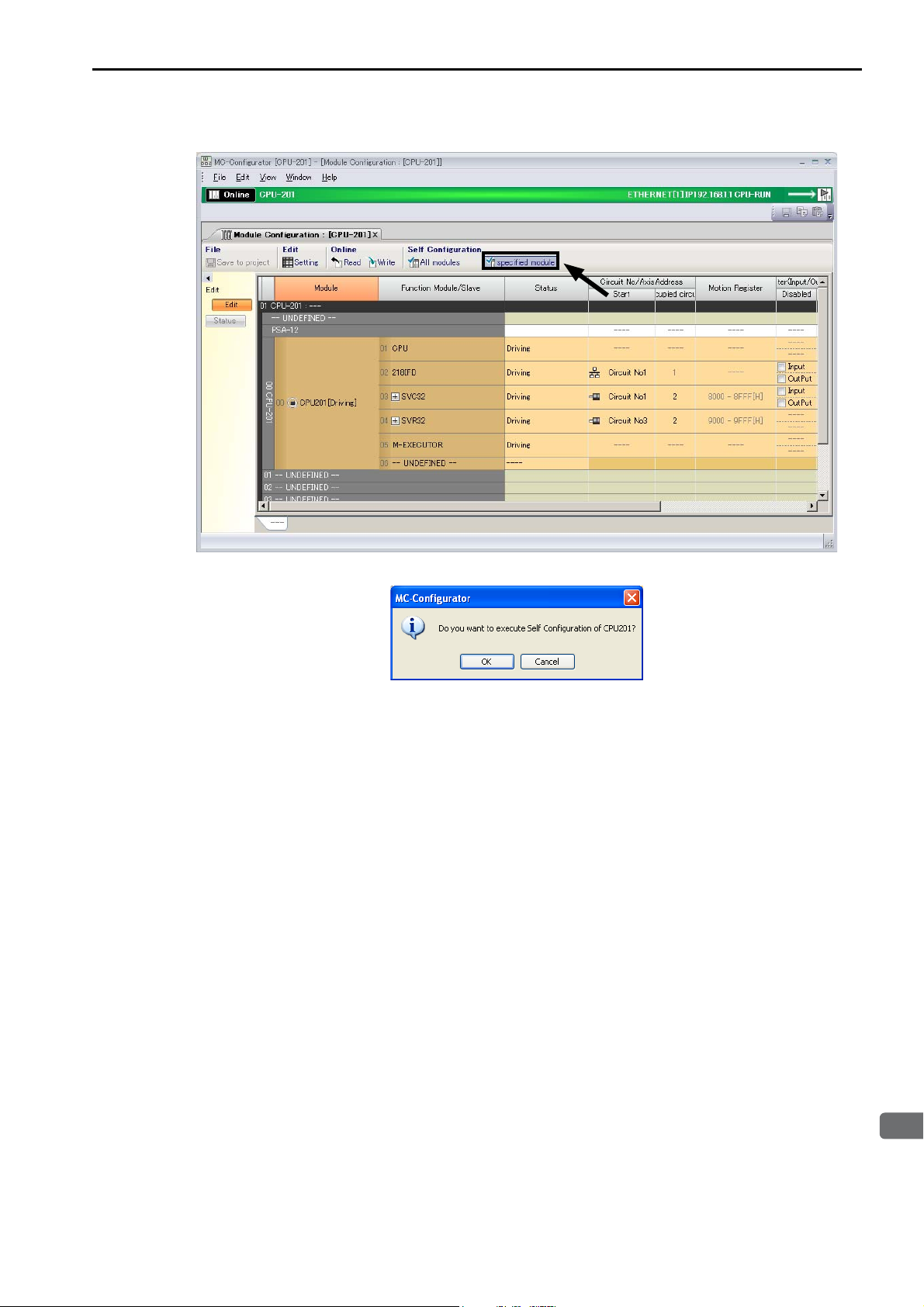
3
CPU Unit Functionality
3. Click the specified module Button on the Launcher.
3.2 Function Modules
Self Configuration
The MC-Configurator Dialog Box will be displayed.
4. Click the OK Button.
Self configuration will be executed only for the new devices that are detected by MECHATROLINK communications.
3-45
Page 96
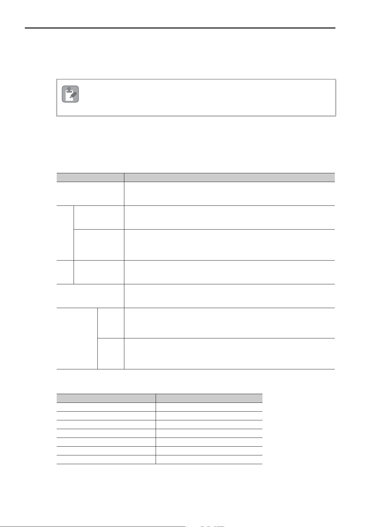
3.2 Function Modules
Note
Self Configuration
Definition Information Updated by Self Configuration
The definition information that is updated by self configuration is described below.
I/O Registers
I/O registers are assigned to the Function Modules (218IFD, SVC32, SVR32, M-EXECUTOR, and
CPUIF) in the CPU Unit as shown below.
I/O registers will also be automatically assigned to any Optional Modules mounted on the Base Unit.
218IFD
SVC
This procedure will not update any of the definitions that were made for existing devices and Function
Modules. The definitions before self configuration will be retained.
Item Settings after Self Configuration
• First I/O registers: IW00000 and OW00000
• Last I/O registers: IW007FF and OW007FF
(input registers: IW00000 to IW007FF, output registers: OW00000 to OW007FF)
MECHATROLINK
Motion parameters
• First I/O registers: IW00800 and OW00800
• Last I/O registers: IW00BFF and OW00BFF
(input registers: IW00800 to IW00BFF, output registers: OW00800 to OW00BFF)
• First motion registers: IW08000 and OW08000
• Last motion registers: IW087FF and OW087FF
(input registers: IW08000 to IW087FF, output registers: OW08000 to OW087FF)
• First motion registers: IW08800 and OW08800
SVR Motion parameters
M-EXECUTOR
For
CPUIF
(Assigned
only when Sub
CPU synchronization is
used.)
highspeed
scan
For lowspeed
scan
• Last motion registers: IW08FFF and OW08FFF
(input registers: IW08800 to IW08FFF, output registers: OW08800 to OW08FFF)
• First I/O registers: IW00C00 and OW00C00
• Last I/O registers: IW00C3F and OW00C3F
(input registers: IW00C00 to IW00C3F, output registers: OW00C00 to OW00C3F)
• First motion registers: IW20000 and OW20000
• Last motion registers: IW207FF and OW207FF
(input registers: IW20000 to IW207FF, output registers: OW20000 to OW207FF)
No registers are assigned.
If you need to use low-speed scan registers, manually set the register addresses to use
with the Start − End Boxes under I/O Registers on the Module Configuration Definition Tab Page.
218IFD Definition
Item Settings after Self Configuration
Local IP Address 192.168.1.1
Subnet Mask 255.255.255.0
Gateway IP Address 0.0.0.0
Module Name Definition CONTROLLER NAME
Engineering Port 9999 (UDP)
MEMOBUS Response Time 0 s
Count of Retry 0
Note: Self configuration sets up the 218IFD for an engineering communications connection with the MPE720.
If you want to use MEMOBUS message communications, manually set up automatic reception or I/O message
communications, or use MSG-SNDE and MSG-RCVE functions.
3-46
Page 97
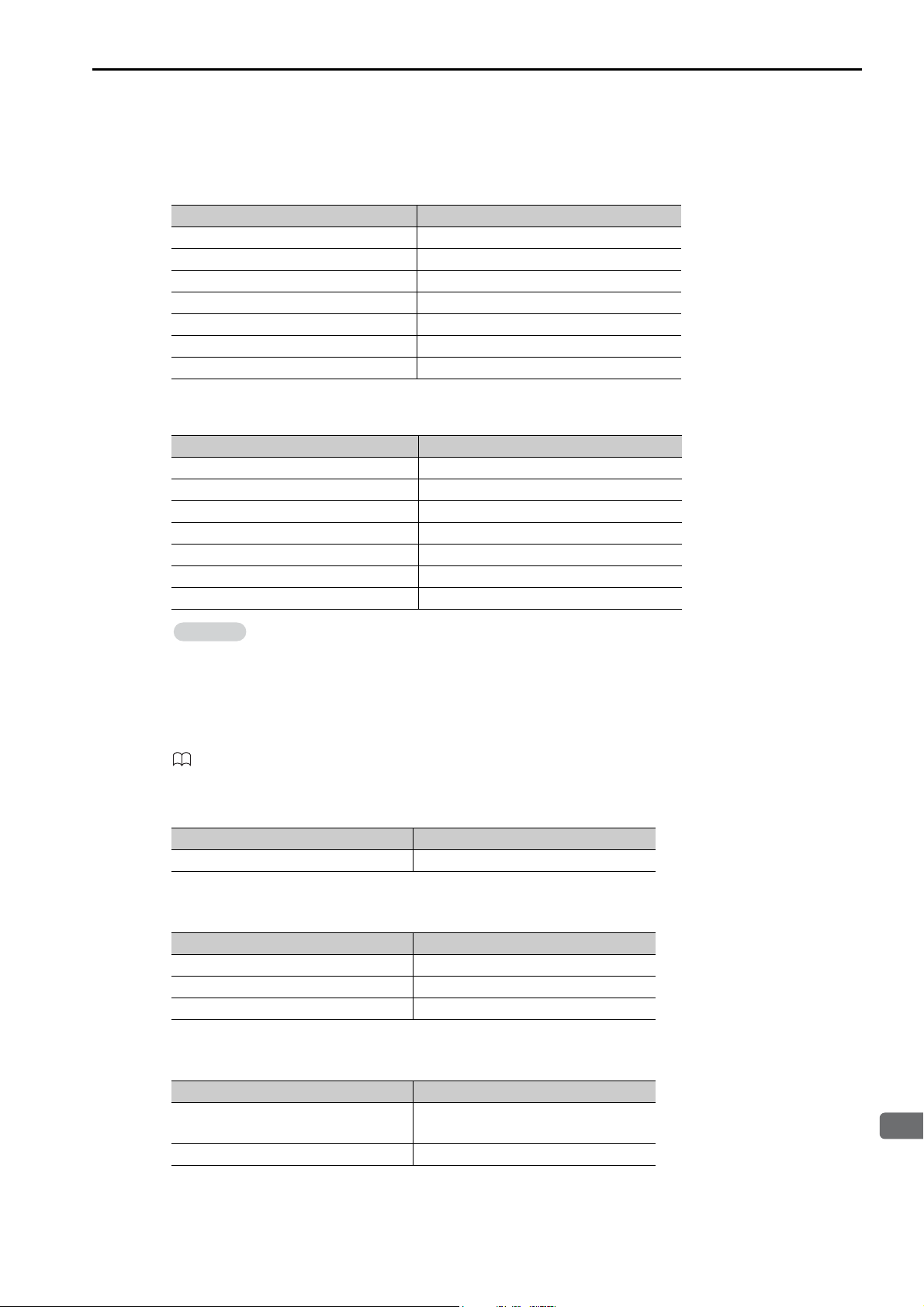
3
CPU Unit Functionality
MECHATROLINK Communications Definition
Information
When Set as the Master
Item Settings after Self Configuration
Master/Slave Master
My station address 0×0001
Communication Cycle 250 μs
Message Communications Enabled
Number of Retry to Slaves 1
Number of connection 8
Slave synchronous function Disabled
When Set as a Slave
Item Settings after Self Configuration
Master/Slave Slave
My station address 0×0003
Communication Cycle −
Message Communications Disabled
Number of Retry to Slaves −
Number of connection 1
Slave synchronous function Disabled
3.2 Function Modules
Self Configuration
To use the Module as a slave, set the parameter settings in the MECHATROLINK communications definition to Slave before performing self configuration in the MPE720.
SVC Definition
Refer to the following manual for details.
MP3000 Series Motion Control User’s Manual (Manual No.: SIEP C880725 11)
SVR Definition
Item Settings after Self Configuration
Defined Axes 32 axes (unused axes)
M-EXECUTOR Definition
Item Settings after Self Configuration
Program Definition Number 8
Program Assignments Not supported.
Control Register Assignments Not supported.
CPUIF Definition (Only when Sub CPU synchronization is used.)
Item Settings after Self Configuration
For high-speed scan
For low-speed scan No registers are assigned.
Input registers: 64 words
Output registers: 64 words
3-47
Page 98
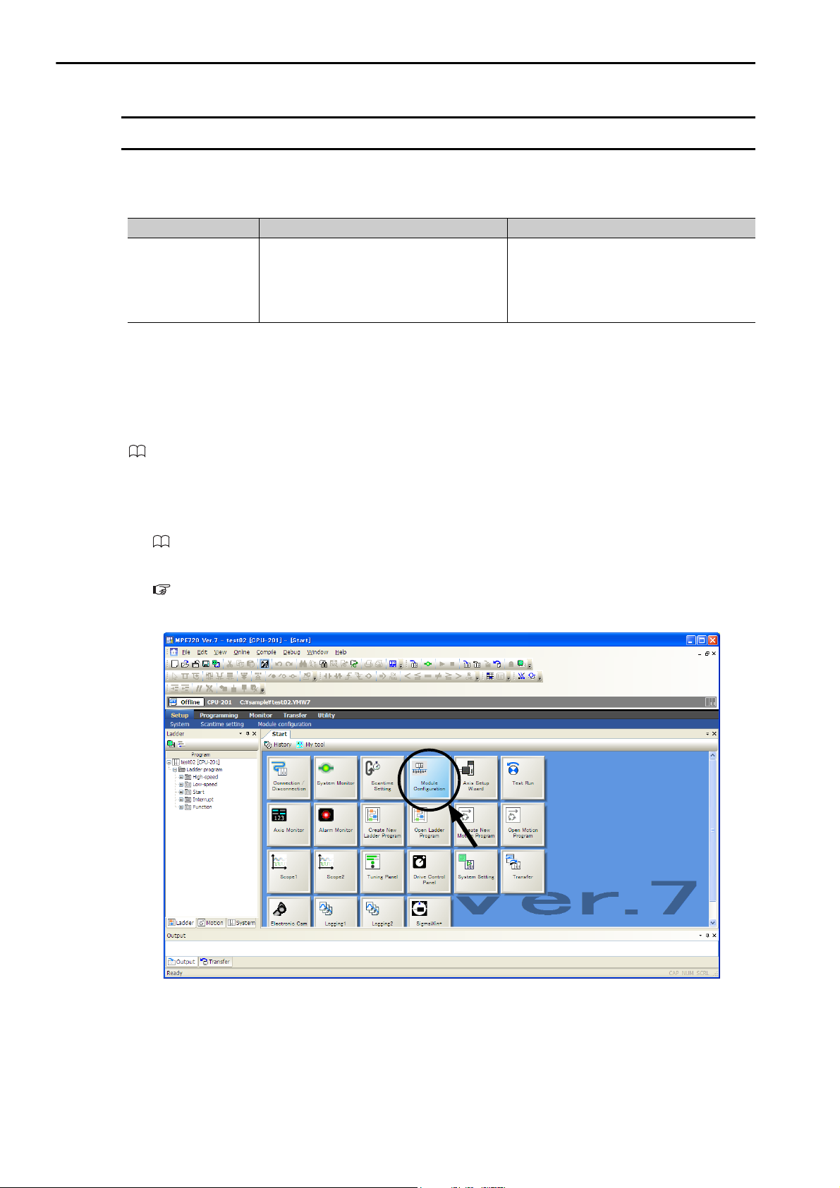
3.2 Function Modules
Communications Function Module (218IFD)
Communications Function Module (218IFD)
This Function Module is used for communications with a host device.
The following table describes the communication features.
Function Module Features Remarks
The MP3000 Controller supports multiple
protocols to enable general-purpose Ether-
Ethernet
Setting Method
Settings are made on the 218IFD Dialog Box after connecting the MP3000-series Controller to the host
device. Use the following procedure to display the 218IFD Dialog Box. Refer to the following manual for
details on settings.
MP3000 Series Communications User’s Manual (Manual No.: SIEP C880725 12)
net communications with PLCs and touch
panels from various manufacturers without
writing special applications.
• Supported Protocols
MODBUS/TCP, OMRON, MELSEC Acompatible 1E/QnA-compatible 3E,
Extended MEMOBUS, MEMOBUS, and
TOYOPUC
1. Connect the Machine Controller to the PC, and start the MPE720.
Refer to the following manual for details.
MP2000/MP3000 Series Machine Controller System Setup Manual (Manual No.: SIEP C880725 00)
2. Execute self configuration as required.
Operating Procedures (page 3-39)
3. Click the Module Configuration Icon on the Start Tab Page.
3-48
Page 99
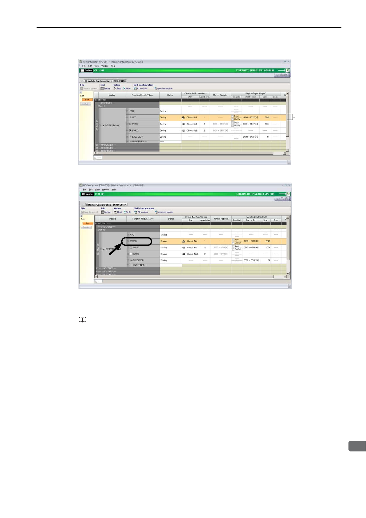
Communications Function Module (218IFD)
3
CPU Unit Functionality
Cells for 218IFD
settings
The following Module Configuration Definition Tab Page will be displayed.
4. Double-click the 218IFD cell.
3.2 Function Modules
The 218IFD Detail Definition Dialog Box will be displayed.
Refer to the following manual for details on settings.
MP3000 Series Communications User’s Manual (Manual No.: SIEP C880725 12)
3-49
Page 100
3.2 Function Modules
Information
Motion Control Function Modules (SVC32 and SVR32)
Motion Control Function Modules (SVC32 and SVR32)
The Motion Control Function Module is used for communications with a MECHATROLINK communications device.
There are two Motion Control Function Modules, the SVC32 and SVR32. Both Modules can provide the
following forms of motion control.
• Position control
• Synchronized phase control
• Torque control
• Speed control
* The SVR32 contains some parameters that you cannot set or monitor.
The features of the SVC32 and SVR32 are described below.
Function Module Features
SVC32
SVR32
*
*
Motion fixed and setting parameters must be set to use these controls.
Controls MECHATROLINK-III-compatible interface devices, such as Servo Drives and I/O
Modules.
Provides an interface for virtual axes. This allows you to test programs and create references
without connecting to physical motors.
Refer to the following manual for details.
MP3000 Series Motion Control User’s Manual (Manual No.: SIEP C880725 11)
Setting Method
Settings are made in the locations given below after the MP3000-series Controller is connected to the
MECHATROLINK device.
• MECHATROLINK Dialog Box
• SVC Definition Tab Page
Use the following procedure to display the tab pages and dialog boxes. Refer to the following manual for
details on settings.
MP3000 Series Motion Control User’s Manual (Manual No.: SIEP C880725 11)
1. Connect the Machine Controller to the PC, and start the MPE720.
Refer to the following manual for details.
MP2000/MP3000 Series Machine Controller System Setup Manual (Manual No.: SIEP C880725 00)
2. Execute self configuration as required.
Operating Procedures (page 3-39)
3-50
 Loading...