

Page 1
YASKAWA AC Drive-J1000
Compact V/f Control Drive
Quick Start Guide
Type: CIMR-JU
Models: 200 V Class, Three-Phase Input: 0.1 to 5.5 kW
200 V Class, Single-Phase Input: 0.1 to 2.2 kW
400 V Class, Three-Phase Input: 0.2 to 5.5 kW
To properly use the product, read this manual thoroughly and retain
for easy reference, inspection, and maintenance. Ensure the end user
receives this manual.
MANUAL NO. TOEP C710606 26D
Receiving
Mechanical Installation
Electrical Installation
Start-Up Programming &
Operation
Troubleshooting
Periodic Inspection &
Maintenance
Peripheral Devices &
Options
Specifications
Parameter List
Standards Compliance
1
2
3
4
5
6
7
A
B
C
Page 2

Copyright © 2008 YASKAWA ELECTRIC CORPORATION. All rights reserved.
All rights reserved. No part of this publication may be reproduced, stored in a retrieval system,
or transmitted, in any form or by any means, mechanical, electronic, photocopying, recording,
or otherwise, without the prior written permission of Yaskawa. No patent liability is assumed
with respect to the use of the information contained herein. Moreover, because Yaskawa is
constantly striving to improve its high-quality products, the information contained in this
manual is subject to change without notice. Every precaution has been taken in the preparation
of this manual. Yaskawa assumes no responsibility for errors or omissions. Neither is any
liability assumed for damages resulting from the use of the information contained in this
publication.
Page 3

Table of Contents
i. PREFACE & GENERAL SAFETY ........................9
i.1 Preface .................................................................. 10
Applicable Documentation ..........................................10
Symbols..................................................................10
Terms and Abbreviations............................................10
i.2
General Safety ....................................................... 11
Supplemental Safety Information..................................11
Safety Messages ......................................................12
Drive Label Warnings ................................................15
Warranty Information .................................................16
Quick Reference.......................................................16
1. RECEIVING .........................................................17
1.1 Section Safety........................................................ 18
1.2 Model Number and Nameplate Check.................... 19
Nameplate...............................................................19
1.3 Component Names ................................................ 22
IP20/Open-Chassis ...................................................22
Front Views .............................................................24
2. MECHANICAL INSTALLATION .........................25
YASKAWA ELECTRIC TOEP C710606 26D YASKAWA AC Drive – J1000 Quick Start Guide
3
Page 4

Table of Contents
2.1 Section Safety.................................................................. 26
2.2
Mechanical Installation .................................................... 29
Installation Environment .......................................................29
Installation Orientation and Spacing........................................ 30
Exterior and Mounting Dimensions .........................................32
ELECTRICAL INSTALLATION.................................... 35
3.
3.1 Section Safety.................................................................. 36
3.2 Standard Connection Diagram......................................... 39
3.3 Main Circuit Connection Diagram.................................... 42
Single-Phase 200 V Class Models BA0001 to BA0010 ...............42
Three-Phase 200 V Class Models 2A0001 to 2A0020
Three-Phase 400 V Class Models 4A0001 to 4A0011 ...............42
3.4 Terminal Block Configuration.......................................... 43
3.5 Protective Covers ............................................................ 44
IP20/Open-Chassis Cover Removal and Installation...................44
3.6 Main Circuit Wiring .......................................................... 46
Main Circuit Terminal Functions .............................................46
Wire Gauges and Tightening Torques .....................................46
Main Circuit Terminal Power Supply and Motor Wiring................ 49
3.7 Control Circuit Wiring...................................................... 52
Control Circuit Terminal Block Functions..................................53
Terminal Configuration......................................................... 54
Wiring Procedure ................................................................56
3.8 I/O Connections ............................................................... 59
Sinking/Sourcing Mode Switch...............................................59
3.9 Main Frequency Reference .............................................. 62
DIP Switch S1 Analog Input Signal Selection............................62
3.10 Braking Resistor .............................................................. 64
Installation......................................................................... 64
3.11 Interlocking with Connected Machinery .......................... 66
Drive Ready Signal .............................................................66
3.12 Wiring Checklist .............................................................. 67
4
YASKAWA ELECTRIC TOEP C710606 26D YASKAWA AC Drive – J1000 Quick Start Guide
Page 5

Table of Contents
4. START-UP PROGRAMMING & OPERATION............. 69
4.1 Section Safety.................................................................. 70
Using the Digital LED Operator........................................ 73
4.2
Keys, Displays, and LEDs.....................................................73
Digital Text Display .............................................................75
LED Screen Displays........................................................... 76
LO/RE LED and RUN LED Indications ....................................76
Menu Structure for Digital LED Operator.................................. 78
4.3 The Drive and Programming Modes ................................ 79
Navigating the Drive and Programming Modes..........................80
Changing Parameter Settings or Values ..................................83
Verifying Parameter Changes: Verify Menu ..............................84
Switching Between LOCAL and REMOTE................................85
Parameters Available in the Setup Group.................................86
4.4 Start-up Flowchart ........................................................... 87
Flowchart: Basic Start-up......................................................87
4.5 Basic Operation ............................................................... 88
Initialize Parameter Values: A1-03.......................................... 88
Frequency Reference Source: b1-01.......................................88
Run Command Input Selection: b1-02 .....................................90
Stopping Method Selection: b1-03..........................................92
Acceleration/Deceleration: C1-01 to C1-04............................... 93
Drive Duty and Carrier Frequency Selection: C6-01 and C6-02 ....95
Multi-Step Speed Operation (4-Step Speed).............................97
E1: V/f Characteristics ....................................................... 101
Motor Parameters: E2-01 to E2-03 ....................................... 104
Digital Output: H2-01 ......................................................... 105
Analog Outputs: H4-01 to H4-03 .......................................... 105
Motor Protection: L1-01 and L1-02 ....................................... 107
Drive Status Monitors: U1-01 to U4-13 .................................. 110
4.6 Powering Up the Drive ....................................................112
Powering Up the Drive and Operation Status Display ............... 112
V/f Pattern Setting............................................................. 113
4.7 No-Load Operation Test Run ..........................................114
No-Load Operation Test Run............................................... 114
YASKAWA ELECTRIC TOEP C710606 26D YASKAWA AC Drive – J1000 Quick Start Guide
5
Page 6

Table of Contents
4.8 Test Run with Load Connected.......................................116
Test Run with the Load Connected....................................... 116
4.9
Verifying and Backing Up Parameter Settings................117
Parameter Access Level: A1-01 ........................................... 117
Password Settings: A1-04, A1-05 ......................................... 117
Copy Function (Optional).................................................... 117
Test Run Checklist .........................................................119
4.10
5. TROUBLESHOOTING ...............................................121
5.1 Section Safety.................................................................122
5.2 Motor Performance Fine Tuning .....................................125
Parameters for Tuning the Drive .......................................... 125
Motor Hunting and Oscillation Control Parameters ................... 126
5.3 Drive Alarms, Faults, and Errors.....................................127
Types of Alarms, Faults, and Errors ...................................... 127
Alarm and Error Displays.................................................... 128
5.4 Fault Detection ...............................................................130
Fault Displays, Causes, and Possible Solutions ...................... 130
5.5 Alarm Detection ..............................................................141
Alarm Codes, Causes, and Possible Solutions........................ 141
5.6 Operator Programming Errors........................................147
oPE Codes, Causes, and Possible Solutions .......................... 147
5.7 Diagnosing and Resetting Faults....................................149
Fault Occurs Simultaneously with Power Loss ........................ 149
If the Drive Still has Power After a Fault Occurs ...................... 149
Viewing Fault History Data After Fault ................................... 149
Fault Reset Methods ......................................................... 150
5.8 Troubleshooting without Fault Display...........................151
Cannot Change Parameter Settings...................................... 151
Motor Does Not Rotate Properly after Pressing RUN Button or
after Entering External Run Command ................................. 152
6. PERIODIC INSPECTION & MAINTENANCE ...........161
6.1 Section Safety.................................................................162
6
YASKAWA ELECTRIC TOEP C710606 26D YASKAWA AC Drive – J1000 Quick Start Guide
Page 7

Table of Contents
6.2 Inspection.......................................................................165
Recommended Daily Inspection........................................... 165
Recommended Periodic Inspection....................................... 166
6.3
Periodic Maintenance .....................................................168
Replacement Parts............................................................ 168
Drive Cooling Fans .........................................................171
6.4
Number of Cooling Fans..................................................... 171
Cooling Fan Replacement .................................................. 172
7. PERIPHERAL DEVICES & OPTIONS ...................... 177
7.1 Section Safety.................................................................178
7.2 Drive Options and Peripheral Devices ............................180
7.3 Connecting Peripheral Devices ......................................182
7.4 Installing Peripheral Devices ..........................................184
Installing a Molded Case Circuit Breaker (MCCB) and Earth
Leakage Circuit Breaker (ELCB) ......................................... 184
Application Precautions when Installing a GFCI....................... 185
Installing a Magnetic Contactor ............................................ 185
Connecting an AC Reactor or DC Link Choke ......................... 186
Connecting a Surge Suppressor .......................................... 187
Connecting a Noise Filter ................................................... 187
EMC Filter Installation........................................................ 190
Zero-Phase Reactor .......................................................... 190
Installing Fuses on the Input Side......................................... 191
Attachment for External Heatsink ......................................... 191
Noise Filter Installation....................................................... 191
Installing a Motor Thermal Overload (oL) Relay on the Drive
Output........................................................................... 191
NEMA Type 1 Kit .............................................................. 193
7.5 Options ...........................................................................198
Interface Options .............................................................. 198
Other Options .................................................................. 198
A. SPECIFICATIONS ...................................................... 199
A.1 Heavy Duty and Normal Duty Ratings.............................200
YASKAWA ELECTRIC TOEP C710606 26D YASKAWA AC Drive – J1000 Quick Start Guide
7
Page 8

Table of Contents
A.2 Single/Three-Phase 200 V Class Drives ..........................201
A.3
Three-Phase 400 V Class Drives .....................................203
Drive Specifications........................................................205
A.4
A.5 Drive Watt Loss Data ......................................................209
A.6 Drive Derating Data.........................................................211
Temperature Derating........................................................ 211
Altitude Derating ............................................................... 212
B. PARAMETER LIST .................................................... 213
B.1 Parameter Groups ..........................................................214
B.2 Parameter Table..............................................................215
A: Initialization Parameters ................................................. 215
b: Application ................................................................... 216
C: Tuning ........................................................................ 217
d: References .................................................................. 220
E: Motor Parameters ......................................................... 222
H Parameters: Multi-Function Terminals ................................ 223
L: Protection Function ........................................................ 229
n: Advanced Performance Set-Up ........................................ 233
o: Operator Related Parameters .......................................... 233
U: Monitors...................................................................... 235
B.3 Defaults by Drive Model and Duty Rating ND/HD............238
C. STANDARDS COMPLIANCE ....................................241
C.1 Section Safety.................................................................242
C.2 European Standards.......................................................245
CE Low Voltage Directive Compliance .................................. 245
EMC Guidelines Compliance............................................... 248
C.3 UL Standards..................................................................254
UL Standards Compliance .................................................. 254
Drive Motor Overload Protection .......................................... 260
INDEX ......................................................................... 263
8
YASKAWA ELECTRIC TOEP C710606 26D YASKAWA AC Drive – J1000 Quick Start Guide
Page 9

Preface & General
Safety
This section provides safety messages pertinent to this product
not heeded, may result in fatality, personal injury, or
that, if
equipment damage. Yaskawa is not responsible for the
consequences of ignoring these instructions.
i.1 PREFACE.........................................................10
i.2 GENERAL SAFETY...........................................11
i
YASKAWA ELECTRIC TOEP C710606 26D YASKAWA AC Drive – J1000 Quick Start Guide
9
Page 10

TERMSTERMS
i.1 Preface
i.1 Preface
Yaskawa manufactures products used as components in a wide variety of industrial systems
and equipment.
of the equipment manufacturer or end user. Yaskawa accepts no responsibility for the way its
products are incorporated into the final system design. Under no circumstances should any
Yaskawa product be incorporated into any product or design as the exclusive or sole safety
control. Without exception, all controls should be designed to detect faults dynamically and
fail safely under all circumstances. All systems or equipment designed to incorporate a product
manufactured by Yaskawa must be supplied to the end user with appropriate warnings and
instructions as to the safe use and operation of that part. Any warnings provided by Yaskawa
must be promptly provided to the end user. Yaskawa offers an express warranty only as to the
quality of its products in conforming to standards and specifications published in the Yaskawa
manual. NO OTHER WARRANTY, EXPRESS OR IMPLIED, IS OFFERED. Yaskawa
assumes no liability for any personal injury, property damage, losses, or claims arising from
misapplication of its products.
u
Applicable Documentation
The following manuals are available for J1000 series drives:
The selection and application of Yaskawa products remain the responsibility
J1000 Series Compact V/f Control Drive Quick Start Guide
Read this manual first. This guide is packaged together with the product. It
contains basic information required to install and wire the drive. This guide
provides basic programming and simple setup and adjustment. Refer to the
J1000 Technical Manual for complete descriptions of drive features and
functions.
J1000 Series Compact V/f Control Drive Technical Manual
This manual describes installation, wiring, operation procedures, functions,
troubleshooting, maintenance, and inspections to perform before operation.
u
Symbols
Note: Indicates a supplement or precaution that does not cause drive damage.
Indicates a term or definition used in this manual.
u
Terms and Abbreviations
• Drive: Yaskawa J1000 Series Drive
• r/min: Revolutions per Minute
• SI-485/J: RS-422/RS-485 Interface for MEMOBUS/Modbus Communication
• V/f: V/f Control
10
YASKAWA ELECTRIC TOEP C710606 26D YASKAWA AC Drive – J1000 Quick Start Guide
Page 11

i.2 General Safety
i.2 General Safety
u
Supplemental Safety Information
General Precautions
• The diagrams in this manual may be indicated without covers or safety shields to show details. Restore
• Any illustrations, photographs, or examples used in this manual are provided as examples only and
• The products and specifications described in this manual or the content and presentation of the manual
• When ordering a new copy of the manual due to damage or loss, contact your Yaskawa representative
• If nameplate becomes worn or damaged, order a replacement from your Yaskawa representative or
Read and understand this manual before installing, operating or servicing this drive. The
drive must be installed according to this manual and local codes.
The following conventions are used to indicate safety messages in this manual. Failure to
heed these messages could result in serious or possibly even fatal injury or damage to the
products or to related equipment and systems.
or shields before operating the drive and run the drive according to the instructions described
covers
in this manual.
may not apply to all products to which this manual is applicable.
may be changed without notice to improve the product and/or the manual.
or the nearest Yaskawa sales office and provide the manual number shown on the front cover.
the nearest Yaskawa sales office.
WARNING
DANGER
Indicates a hazardous situation, which, if not avoided, will result in death or serious
injury.
WARNING
Indicates a hazardous situation, which, if not avoided, could result in death or serious
injury.
WARNING! will also be indicated by a bold key word embedded in the text followed by an italicized safety
message.
YASKAWA ELECTRIC TOEP C710606 26D YASKAWA AC Drive – J1000 Quick Start Guide
11
Page 12

i.2 General Safety
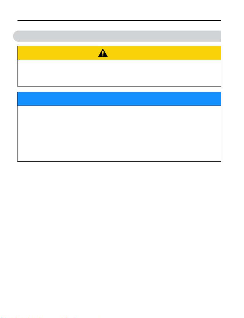
CAUTION
Indicates a hazardous situation, which, if not avoided, could result in minor or
moderate injury.
CAUTION! will also be indicated by a bold key word embedded in the text followed by an italicized safety
message.
NOTICE
Indicates a property damage message.
NOTICE: will also be indicated by a bold key word embedded in the text followed by an italicized safety
message.
u
Safety Messages
DANGER
Heed the safety messages in this manual.
Failure to comply will result in death or serious injury.
The operating company is responsible for any injuries or equipment damage resulting from
failure to heed the warnings in this manual.
Electrical Shock Hazard
Do not connect or disconnect wiring while the power is on.
Failure to comply will result in death or serious injury.
Before servicing, disconnect all power to the equipment. The internal capacitor remains
charged even after the power supply is turned off. The charge indicator LED will extinguish
when the DC bus voltage is below 50 Vdc. To prevent electric shock, wait at least one minute
after all indicators are OFF and measure the DC bus voltage level to confirm safe level.
12
YASKAWA ELECTRIC TOEP C710606 26D YASKAWA AC Drive – J1000 Quick Start Guide
Page 13

i.2 General Safety
WARNING
Sudden Movement Hazard
System may
injury.
Clear all personnel from the drive, motor and machine area before applying power. Secure
covers, couplings, shaft keys and machine loads before applying power to the drive.
start unexpectedly upon application of power, resulting in death or serious
Electrical Shock Hazard
Do not attempt to modify or alter the drive in any way not explained in this manual.
Failure to comply could result in death or serious injury.
Yaskawa is not responsible for any modification of the product made by the user. This
product must not be modified.
Do not allow unqualified personnel to use equipment.
Failure to comply could result in death or serious injury.
Maintenance, inspection, and replacement of parts must be performed only by authorized
personnel familiar with installation, adjustment and maintenance of AC drives.
Do not remove covers or touch circuit boards while the power is on.
Failure to comply could result in death or serious injury.
Fire Hazard
Do not use an improper voltage source.
Failure to comply could result in death or serious injury by fire.
Verify that the rated voltage of the drive matches the voltage of the incoming power supply
before applying power.
Crush Hazard
Do not use this drive in lifting applications without installing external safety circuitry
to prevent accidental dropping of the load.
The drive does not possess built-in load drop protection for lifting applications.
Failure to comply could result in death or serious injury from falling loads.
Install electrical and/or mechanical safety circuit mechanisms independent of drive circuitry.
YASKAWA ELECTRIC TOEP C710606 26D YASKAWA AC Drive – J1000 Quick Start Guide
13
Page 14

i.2 General Safety
CAUTION
Crush Hazard
Do not carry the drive by the front cover.
Failure to comply may result in minor or moderate injury from the main body of the drive
falling.
NOTICE
Observe proper electrostatic discharge procedures (ESD) when handling the drive and
circuit boards.
Failure to comply may result in ESD damage to the drive circuitry.
Never connect or disconnect the motor from the drive while the drive is outputting
voltage.
Improper equipment sequencing could result in damage to the drive.
Do not perform a withstand voltage test on any part of the drive.
Failure to comply could result in damage to the sensitive devices within the drive.
Do not operate damaged equipment.
Failure to comply could result in further damage to the equipment.
Do not connect or operate any equipment with visible damage or missing parts.
Install adequate branch circuit short circuit protection per applicable codes.
Failure to comply could result in damage to the drive.
The drive is suitable for circuits capable of delivering not more than 31,000 RMS
symmetrical Amperes, 240 Vac maximum (200 V Class) and 480 Vac maximum (400 V
Class).
Do not expose the drive to halogen group disinfectants.
Failure to comply may cause damage to the electrical components in the drive.
Do not pack the drive in wooden materials that have been fumigated or sterilized.
Do not sterilize the entire package after the product is packed.
14
YASKAWA ELECTRIC TOEP C710606 26D YASKAWA AC Drive – J1000 Quick Start Guide
Page 15
i.2 General Safety
u
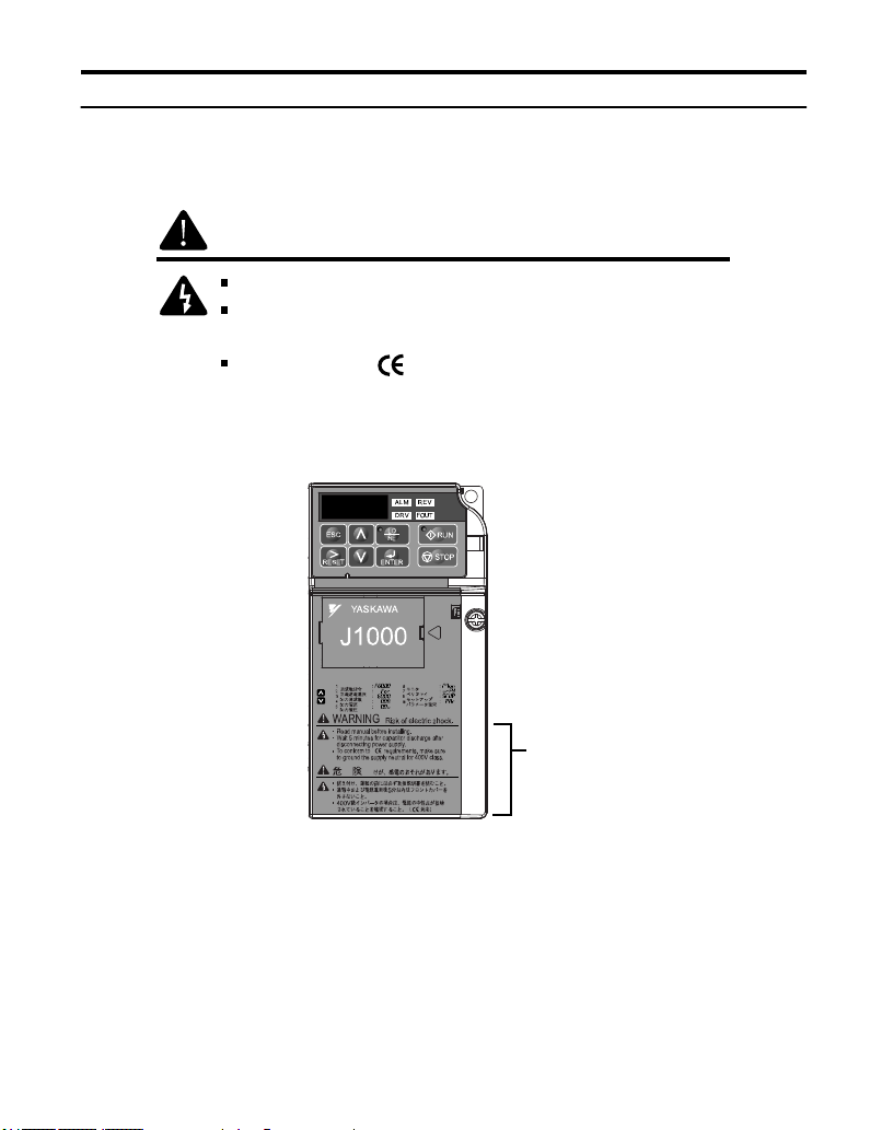
Drive Label Warnings
Always heed the warning information listed in Figure i.1 in the position shown in Figure i.
2.
WARNING
Risk of electric shock.
Read manual before installing.
Wait 1 minute for capacitor discharge after
y
disconnecting power suppl
.
To conform to requirements, make sure
to ground the supply neutral for 400V class.
Figure i.1 Warning Information
Warning
Label
Figure i.2 Warning Information Position
YASKAWA ELECTRIC TOEP C710606 26D YASKAWA AC Drive – J1000 Quick Start Guide
15
Page 16

i.2 General Safety
u
Warranty Information
Restrictions
n
The drive was not designed or manufactured for use in devices or systems that may directly
affect or threaten human lives or health.
Customers who intend to use the product described in this manual for devices or systems
relating to transportation, health care, space aviation, atomic power, electric power, or in
underwater applications must first contact their Yaskawa representatives or the nearest
Yaskawa sales office.
This product has been manufactured under strict quality-control guidelines. However, if this
product is
to be installed in any location where failure of this product could involve or result
in a life-and-death situation or loss of human life or in a facility where failure may cause a
serious accident or physical injury, safety devices must be installed to minimize the likelihood
of any accident.
u
Quick Reference
Run a Motor of One-Frame Larger Capacity
When using this drive for variable torque loads such as fans and pumps, a motor one frame size larger can be used.
Know the Details of Safety Measures
The functions listed below affect the safe operation of the drive. Ensure that the settings fit the application requirements
prior to operation.
Safe operations. Run by power on. Parameter setting b1-17.
LED operator stop key priority selection. Parameter o2-02.
Enter press required after changing the keypad frequency reference. Parameter o2-05.
Operation interlock when program mode is selected. Parameter b1-08.
Standards Compliance
Refer to European Standards on page 245 and Refer
254.
16
YASKAWA ELECTRIC TOEP C710606 26D YASKAWA AC Drive – J1000 Quick Start Guide
to UL Standards on page
Page 17

1
Receiving
This chapter describes the proper inspections to perform after
receiving the
and components.
1.1 SECTION SAFETY.............................................18
1.2 MODEL NUMBER AND NAMEPLATE CHECK...19
1.3 COMPONENT NAMES.......................................22
YASKAWA ELECTRIC TOEP C710606 26D YASKAWA AC Drive – J1000 Quick Start Guide
drive and illustrates the different enclosure types
17
Page 18
1.1 Section Safety
1.1 Section Safety
CAUTION
Do not carry the drive by the front cover.
Failure to
injury.
Observe proper electrostatic discharge procedures (ESD) when handling the drive and
circuit boards.
Failure to comply may result in ESD damage to the drive circuitry.
A motor
fed motor and the operating speed range may reduce motor cooling capacity.
Ensure that the motor is suitable for drive duty and/or the motor service factor is adequate
to accommodate the additional heating with the intended operating conditions.
comply may cause the main body of the drive to fall, resulting in minor or moderate
NOTICE
connected to a PWM drive may operate at a higher temperature than a utility-
18
YASKAWA ELECTRIC TOEP C710606 26D YASKAWA AC Drive – J1000 Quick Start Guide
Page 19
IND.CONT.EQ.
7J48
PASS
:
: AC3PH 200-240V 50 / 60Hz 2.7A / 1.4A
: AC3PH 0-240V 0-400Hz 1.2A / 0.8A
: 0.9 kg
:
:
: E131457 IP20
MODEL
MAX APPLI. MOTOR : 3.5A/3.0A REV : A
INPUT
OUTPUT
MASS
O / N
S / N
FILE NO
I
H
G
F
D
B
A
YASKAWA ELECTRIC CORPORATION MADE IN JAPAN
2-1 Kurosaki-shiroishi, Yahatanishi-Ku, Kitakyushu 806-0004 Japan
C
E
CIMR-J
1.2 Model Number and Nameplate Check
1.2 Model Number and Nameplate Check
Please perform the following tasks after receiving the drive:
• Inspect the drive for damage.
If the drive appears damaged upon receipt, contact the shipper immediately.
Verify receipt of the correct model by checking the information on the nameplate.
•
• If you have received the wrong model or the drive does not function properly, contact your
supplier.
u
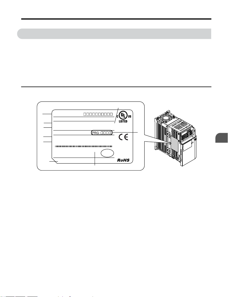
Nameplate
Receiving
1
A – Normal Duty Amps /
Heavy Duty Amps
B –
Software version
C – Enclosure type
D –
E – Serial number
<1> The address of the head office of Yaskawa Electric Corporation (responsible for product
liability) is shown on the nameplate.
YASKAWA ELECTRIC TOEP C710606 26D YASKAWA AC Drive – J1000 Quick Start Guide
<1>
Address
Figure 1.1 Nameplate Information Example
F – Lot number
G – Output specifications
H – Input specifications
I – AC drive model
19
Page 20
CIMR- J U 2 A
0001 B
A A
Drive
J1000
Series
Design
Revision
Order
No. Enclosure Type
IP20/OpenChassis
B
No.
Environmental
Specification <1>
A
M
N
S
Standard
Humidity- and
dust-resistant
Oil-resistant
Vibration-resistant
No.
Customized
Specifications
A Standard model
No.
Region
Code
A Japan
No. Voltage Class
B
1-phase, 200-240 Vac
3-phase, 380-480 Vac
3-phase, 200-240 Vac
2
4
B China
C Europe
T Asia
U USA
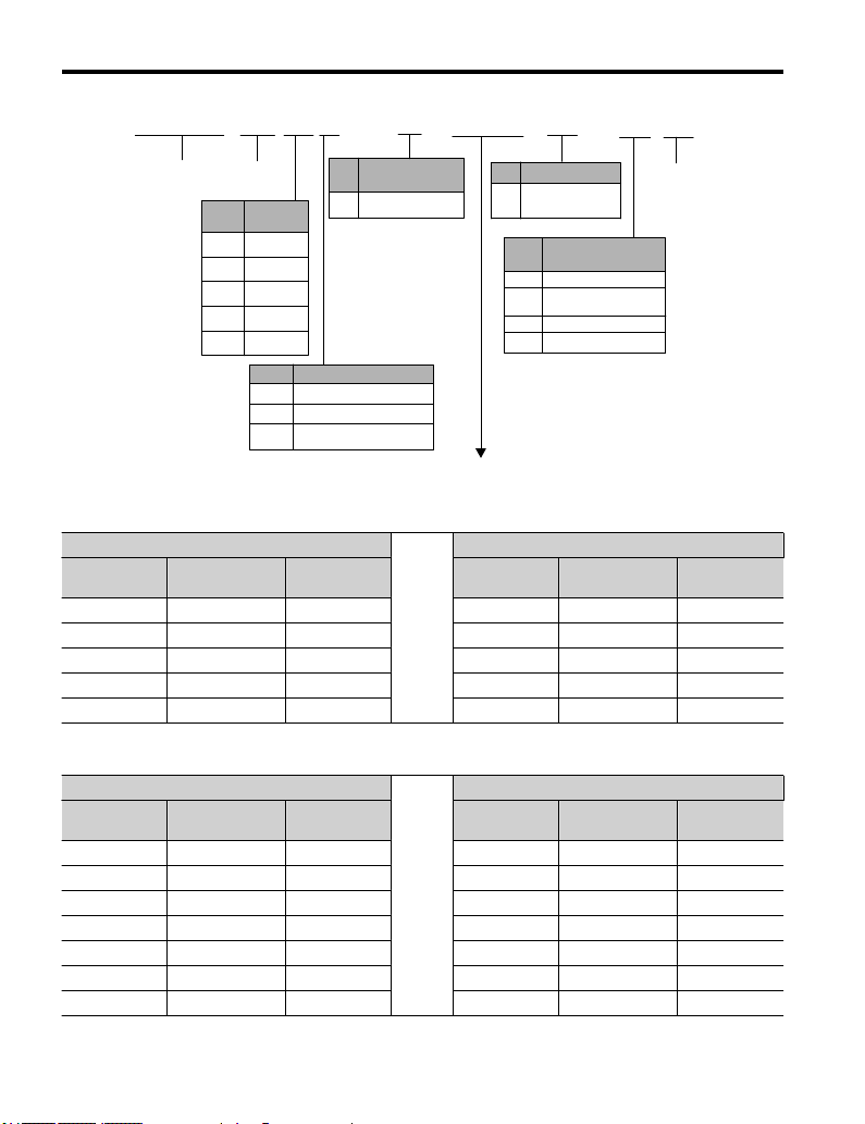
Refer to the tables below.
1.2 Model Number and Nameplate Check
Single-Phase 200 V
n
Normal Duty Heavy Duty
No.
Max. Motor
Capacity kW
0001 0.2 1.2 0001 0.1 0.8
0002 0.4 1.9 0002 0.2 1.6
0003 0.75 3.3 0003 0.4 3.0
0006 1.1 6.0 0006 0.75 5.0
0010 2.2 9.6 0010 1.5 8.0
Rated Output
Current A
No.
Max. Motor
Capacity kW
Rated Output
Current A
Three-Phase 200 V
n
Normal Duty Heavy Duty
No.
0001 0.2 1.2 0001 0.1 0.8
0002 0.4 1.9 0002 0.2 1.6
0004 0.75 3.5 0004 0.4 3.5
0006 1.1 6.0 0006 0.75 6.0
0010 2.2 9.6 0010 1.5 9.6
0012 3.0 12.0 0012 2.2 12.0
0020 5.5 19.6 0020 3.7 17.5
20
Max Motor
Capacity kW
YASKAWA ELECTRIC TOEP C710606 26D YASKAWA AC Drive – J1000 Quick Start Guide
Rated Output
Current A
No.
Max Motor
Capacity kW
Rated Output
Current A
Page 21

1.2 Model Number and Nameplate Check
Three-Phase 400 V
n
Normal Duty Heavy Duty
No.
0001 0.4 1.2 0001 0.2 1.2
0002 0.75 2.1 0002 0.4 1.8
0004 1.5 4.1 0004 0.75 3.4
0005 2.2 5.4 0005 1.5 4.8
0007 3.0 6.9 0007 2.2 5.5
0009 3.7 8.8 0009 3.0 7.2
0011 5.5 11.1 0011 3.7 9.2
Max. Motor
Capacity kW
Rated Output
Current A
No.
Max. Motor
Capacity kW
Rated Output
Current A
Receiving
1
YASKAWA ELECTRIC TOEP C710606 26D YASKAWA AC Drive – J1000 Quick Start Guide
21
Page 22

1.3 Component Names
1.3 Component Names
This section illustrates drive components in the IP20/Open-Chassis models.
Refer to NEMA Type 1 Kit on page 193 for information on using the NEMA Type 1 Kit
option to create a NEMA Type 1 rating.
u
IP20/Open-Chassis
Single-Phase AC 200 V BA0001B to BA0003B
n
Three-Phase AC 200 V 2A0001B to 2A0006B
K
J
I
A
H
B
G
F
C
E
A – Mounting hole
Heatsink
B –
C – Cable cover
D – Terminal cover
E – Front cover screw
F – Option connector cover
Figure 1.2 Exploded View of IP20/Open-Chassis Type Components
<1>
Models BA0001B to BA0003B and 2A0001B to 2A0004B do not have a cooling fan or a
cooling fan cover.
22
YASKAWA ELECTRIC TOEP C710606 26D YASKAWA AC Drive – J1000 Quick Start Guide
(Model 2A0006B)
D
G – Front cover
H – LED operator Refer to
Using the Digital LED
Operator on page 73
I – Case
J –
Cooling fan
K –
Fan cover
<1>
<1>
Page 23

Single-Phase AC 200 V BA0006B to BA0010B
n
Three-Phase AC 200 V 2A0010B to 4A0020B
Three-Phase AC 400 V 4A0001B to 4A0011B
L
K
1.3 Component Names
J
I
H
G
D
F
A – Mounting hole
B –
Heatsink
C – Cable cover
D – Terminal cover
E – Bottom cover
F – Front cover screw
Figure 1.3 Exploded view of IP20/Open-Chassis Type Components
<1> Models
BA0006B
and 4A0001B to 4A0004B do not have a cooling fan or a cooling fan cover.
(Model 2A0012B)
E
G – Option connector cover
H – Front cover
I – LED operator Refer to
Using the Digital LED
Operator on page 73
J – Case
K –
Cooling fan
L –
Fan cover
<1>
<1>
A
B
Receiving
1
C
YASKAWA ELECTRIC TOEP C710606 26D YASKAWA AC Drive – J1000 Quick Start Guide
23
Page 24

G
F
A
B
C
D
E
A
B
C
D
E
F
G
2A0006B
2A0012B
1.3 Component Names
u
Front Views
A – DIP switch S1 Refer to
DIP Switch S1 Analog
Input Signal
page 62
B – DIP switch S3 Refer to
Sinking/Sourcing Mode
Switch on page 59
C – Control circuit terminal
Refer to Control Circuit
Wiring on page 52
D – Main circuit terminal
Refer to Wiring the Main
Circuit Terminal on page
51
Selection on
Figure 1.4 Front Views of Drives
24
YASKAWA ELECTRIC TOEP C710606 26D YASKAWA AC Drive – J1000 Quick Start Guide
E – Ground terminal
F – Terminal cover
G – Option unit connector
Refer to Options on page
198
Page 25

2
Mechanical
Installation
This chapter explains how to properly mount and install the
drive.
2.1 SECTION SAFETY.............................................26
MECHANICAL INSTALLATION..........................29
2.2
YASKAWA ELECTRIC TOEP C710606 26D YASKAWA AC Drive – J1000 Quick Start Guide
25
Page 26
2.1 Section Safety
2.1 Section Safety
WARNING
Fire Hazard
Provide sufficient
inside an enclosed panel or cabinet.
Failure to comply could result in overheating and fire.
The airflow over an IP20/Open-Chassis drive should be less than 50 °C, while an IP20/
NEMA Type 1 drive using the NEMA Type 1 Kit option should have an airflow cooler than
40 °C.
Do not carry the drive by the front cover.
Failure to comply may result in minor or moderate injury from the main body of the drive
falling.
cooling with a fan or air conditioning unit when installing the drive
CAUTION
Crush Hazard
26
YASKAWA ELECTRIC TOEP C710606 26D YASKAWA AC Drive – J1000 Quick Start Guide
Page 27

2.1 Section Safety
NOTICE
Observe proper electrostatic discharge (ESD) procedures when handling the drive.
Failure to comply could result in ESD damage to the drive circuitry.
It may be difficult to perform maintenance on the cooling fans of drives installed in a
vertical row inside an enclosure.
Ensure adequate spacing at the top of the drive to perform cooling fan replacement when
required.
Operating the motor in the low-speed range diminishes the cooling effects, increases
motor temperature, and may lead to motor damage by overheating.
Reduce the motor torque in the low-speed range whenever using a standard blower cooled
motor.
or vector motor. Select a motor that is compatible with the required load torque and operating
speed range.
Do not operate motors above the maximum rated RPM.
Failure to comply may lead to bearing or other mechanical motor failures.
The speed range for continuous operation differs according to the lubrication method
and motor manufacturer.
If the motor is to be operated at a speed higher than the rated speed, consult with the
manufacturer.
Continuously operating an oil-lubricated motor in the low-speed range may result in burning.
100% torque is required continuously at low speed, consider using a special drive
If
Mechanical Installation
2
YASKAWA ELECTRIC TOEP C710606 26D YASKAWA AC Drive – J1000 Quick Start Guide
27
Page 28

2.1 Section Safety
NOTICE
When the wiring distance is greater than 100 meters, pay special attention to the motor
insulation voltage or use a drive-rated motor.
Failure to comply could lead to motor winding failure.
Motor vibration may increase when operating a machine in variable-speed mode, if
that machine previously operated at a constant speed.
Install
vibration-proof
a frequency resonating the machine.
The motor may require more acceleration torque with drive operation than with a
commercial power supply.
Set a proper V/f pattern by checking the load torque characteristics of the machine to be
used with the motor.
The rated input current of submersible motors is higher than the rated input current
of standard motors.
Select an appropriate drive according to its rated output current. When the distance between
the motor and drive is long, use a cable thick enough to connect the motor to the drive to
prevent motor torque reduction.
When using an explosion-proof motor, it must be subject to an explosion-proof test in
conjunction with the drive.
This is also applicable when an existing explosion-proof motor is to be operated with the
drive. Since the drive itself is not explosion-proof, always install it in a safe place.
Do not use a drive for a single-phase motor.
Replace the motor with a three-phase motor.
If an oil-lubricated gearbox or speed reducer is used in the power transmission
mechanism, oil lubrication will be affected when the motor operates only in the low
speed range.
The power transmission mechanism will make noise and experience problems with service
life and durability if the motor is operated at a speed higher than the rated speed.
rubber on the motor base or use the frequency jump function to skip
28
YASKAWA ELECTRIC TOEP C710606 26D YASKAWA AC Drive – J1000 Quick Start Guide
Page 29

2.2 Mechanical Installation
2.2 Mechanical Installation
This section outlines specifications, procedures, and environment for proper mechanical
installation of the drive.
u
Installation Environment
To help prolong the optimum performance life of the drive, install the drive in the proper
environment. The table below provides a description of the appropriate environment for the
drive.
Table 2.1 Installation Environment
Environment Conditions
Installation Area Indoors
IP20/NEMA Type 1 enclosure: -10 °C to +40 °C (14 °F to 104 °F)
IP20/IP00 Open-Chassis enclosure: -10 °C to +50 °C (14 °F to 122 °F)
Ambient
Temperature
Humidity 95% RH or less and free of condensation
Storage Temperature -20 °C to +60 °C (-4 °F to +104 °F)
Surrounding Area
Altitude
Vibration
Orientation Install the drive vertically to maintain maximum cooling effects.
NOTICE: Prevent foreign matter such as metal shavings or wire clippings from falling into the drive during
installation and project construction. Failure to comply could result in damage to the drive. Place a temporary
cover over the top of the drive during installation. Remove the temporary cover before startup, as the cover
will reduce ventilation and cause the drive to overheat.
NOTICE: Avoid placing drive peripheral devices, transformers, or other electronics near the drive. Failure to
comply could result in erroneous operation. If such devices must be used in close proximity to the drive, take
proper steps to shield the drive from noise.
Finless Type: IP20 enclosure: -10 °C to +50 °C (14 °F to 122 °F)
Drive reliability improves in environments without wide temperature fluctuations.
When using an enclosure panel, install a cooling fan or air conditioner in the area to ensure
that the air temperature inside the enclosure does not exceed the specified levels.
Do not allow ice to develop on the drive.
Install the drive in an area free from:
•
oil mist and dust
metal shavings, oil, water or other foreign materials
•
• radioactive materials
• combustible materials (e.g., wood)
• harmful gases and liquids
• excessive vibration
• chlorides
• direct sunlight
Up to 1000 meters without derating; up to 3000 meters with output current, ambient
temperature, and voltage derating.
10 to 20 Hz at 9.8 m/s
20 to 55 Hz at 5.9 m/s
2
2
Mechanical Installation
2
YASKAWA ELECTRIC TOEP C710606 26D YASKAWA AC Drive – J1000 Quick Start Guide
29
Page 30

2.2 Mechanical Installation
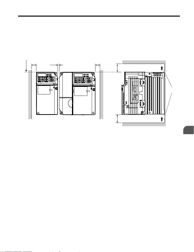
u
Installation Orientation and Spacing
Install the drive upright as illustrated in Figure 2.1 to maintain proper cooling.
A – Correct B – Incorrect
Single Drive Installation
n
A
Figure 2.1 Correct Installation Orientation
B
B
Figure 2.2 explains the required installation spacing to maintain sufficient space for airflow
and wiring.
Install the heatsink against a closed surface to avoid diverting cooling air around
the heatsink.
Side Clearance
A
A
Top/Bottom Clearance
C
B
Note: The space
30
C
A – 30 mm minimum
B – Airflow direction
Figure 2.2 Correct Installation Spacing
required on the left and right sides of the drive are the same for IP20/Open-Chassis drives and
IP20/NEMA Type 1 drives using the NEMA Type 1 Kit option.
YASKAWA ELECTRIC TOEP C710606 26D YASKAWA AC Drive – J1000 Quick Start Guide
C – 100 mm minimum
Page 31
2.2 Mechanical Installation
Multiple Drive Installation
n
When installing
multiple drives into the same enclosure panel, mount the drives according to
Figure 2.2. When mounting drives with a minimum side-by-side clearance of 2 mm according
to Figure 2.3, derating must be considered and parameter L8-35 must be set. Refer to
Parameter List on page 213.
A
B
2 mm
B
C
D
C
A – Line up the tops of the
drives.
B – 30 mm minimum
Figure 2.3 Space Between Drives (Side-by-Side Mounting)
Note: When installing
YASKAWA ELECTRIC TOEP C710606 26D YASKAWA AC Drive – J1000 Quick Start Guide
up. Leave space between the top and bottom of stacked drives for cooling fan replacement if required.
Using this method, it is possible to replace the cooling fans later.
drives of different heights in the same enclosure panel, the tops of the drives should line
C – 100 mm minimum
D – Airflow direction
Mechanical Installation
2
31
Page 32
2.2 Mechanical Installation
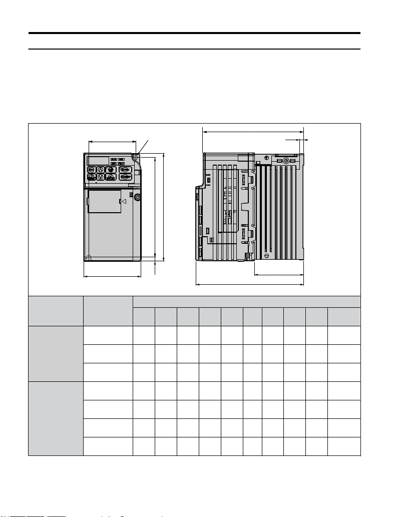
u
Exterior and Mounting Dimensions
Refer to NEMA Type 1 Kit on page 193
for exterior and mounting dimensions for drives
using the NEMA Type 1 Kit option.
IP20/Open-Chassis Drives
n
Table 2.2 IP20/Open-Chassis (without an EMC filter)
W1
2-M4
H1H2
H
D2
t1
Voltage Class
Single-Phase
200 V Class
Three-Phase
200 V Class
32
W
Drive
Model
BA0001B
BA0002B
BA0003B
2A0001B
2A0002B
2A0004B
2A0006B
W H D W1 H1 H2 D1 D2 t1
68
128
(2.7)
(5.0)76(3.0)56(2.2)
68
128
(2.7)
(5.0)76(3.0)56(2.2)
68
128
(2.7)
68
(2.7)
68
(2.7)
68
(2.7)
68
(2.7)
YASKAWA ELECTRIC TOEP C710606 26D YASKAWA AC Drive – J1000 Quick Start Guide
118
(5.0)
(4.6)56(2.2)
128
(5.0)76(3.0)56(2.2)
128
(5.0)76(3.0)56(2.2)
128
108
(5.0)
(4.3)56(2.2)
128
128
(5.0)
(5.0)56(2.2)
Dimensions mm (in)
118
(4.6)5(0.2)
118
(4.6)5(0.2)
118
(4.6)5(0.2)
118
(4.6)5(0.2)
118
(4.6)5(0.2)
118
(4.6)5(0.2)
118
(4.6)5(0.2)
D1
D
6.5
67.5
(0.3)
(2.7)3(0.1)
6.5
67.5
(0.3)
(2.7)3(0.1)
38.5
109.5
(1.5)
(4.3)5(0.2)
6.5
67.5
(0.3)
(2.7)3(0.1)
6.5
67.5
(0.3)
(2.7)3(0.1)
38.5
99.5
(1.5)
(3.9)5(0.2)
58.5
119.5
(2.3)
(4.7)5(0.2)
Wt. kg
(lb.)
0.6
(1.3)
0.6
(1.3)
1.0
(2.2)
0.6
(1.3)
0.6
(1.3)
0.9
(2.0)
1.1
(2.4)
Page 33

2.2 Mechanical Installation
Table 2.3 IP20/Open-Chassis (without an EMC filter)
Voltage Class
Single-Phase
200 V Class
Three-Phase
200 V Class
W1
W
Drive
Model
BA0006B
BA0010B
2A0010B
2A0012B
2A0020B
D
D2
D1
129
(5.1)5(0.2)
145.5
(5.7)5(0.2)
120.5
(4.7)5(0.2)
129
(5.1)5(0.2)
134.5
(5.3)5(0.2)
4-M4
H
H2 H1
Dimensions mm (in)
W H D W1 H1 H2 D1 D2 t1
108
128
(4.3)
108
(4.3)
108
(4.3)
108
(4.3)
140
(5.5)
(5.0)
128
(5.0)
128
(5.0)
128
(5.0)
128
(5.0)
137.5
(5.4)96(3.8)
154
(6.1)96(3.8)
129
(5.1)96(3.8)
137.5
5.496(3.8)
143
(5.6)
118
(4.6)5(0.2)58(2.3)
118
(4.6)5(0.2)58(2.3)
118
(4.6)5(0.2)58(2.3)
118
(4.6)5(0.2)58(2.3)
128
118
(5.0)
(4.6)5(0.2)65(2.6)
t1
Wt. kg
(lb.)
1.7
(3.8)
1.8
(4.0)
1.7
(3.8)
1.7
(3.8)
2.4
(5.3)
Mechanical Installation
2
YASKAWA ELECTRIC TOEP C710606 26D YASKAWA AC Drive – J1000 Quick Start Guide
33
Page 34

2.2 Mechanical Installation
Voltage Class
Three-Phase
400 V Class
W1
W
Drive
Model
4A0001B
4A0002B
4A0004B
4A0005B
4A0007B
4A0009B
4A0011B
4-M4
H
H2 H1
D2
D
Dimensions mm (in)
W H D W1 H1 H2 D1 D2 t1
108
128
(4.3)
(5.0)81(3.2)96(3.8)
108
128
(4.3)
(5.0)99(3.9)96(3.8)
108
128
(4.3)
(5.0)
108
128
(4.3)
(5.0)
108
128
(4.3)
(5.0)
108
128
(4.3)
(5.0)
140
128
(5.5)
(5.0)
137.5
(5.4)96(3.8)
154
(6.1)96(3.8)
154
(6.1)96(3.8)
154
(6.1)96(3.8)
143
(5.6
118
(4.6)5(0.2)10(0.4)
118
(4.6)5(0.2)28(1.1)
118
(4.6)5(0.2)58(2.3)
118
(4.6)5(0.2)58(2.3)
118
(4.6)5(0.2)58(2.3)
118
(4.6)5(0.2)58(2.3)
128
118
(5.0)
(4.6)5(0.2)65(2.6)
72.5
(2.9)5(0.2)
90.5
(3.6)5(0.2)
129
(5.1)5(0.2)
145.5
(5.7)5(0.2)
145.5
(5.7)5(0.2)
145.5
(5.7)5(0.2)
134.5
(5.3)5(0.2)
t1
D1
Wt. kg
(lb.)
1.0
(2.2)
1.2
(2.7)
1.7
(3.8)
1.7
(3.8)
1.7
(3.8)
1.7
(3.8)
2.4
(5.3)
34
YASKAWA ELECTRIC TOEP C710606 26D YASKAWA AC Drive – J1000 Quick Start Guide
Page 35

3
Electrical
Installation
This chapter explains proper procedures for wiring the control
circuit terminals, motor and power supply.
3.1 SECTION SAFETY.............................................36
STANDARD CONNECTION DIAGRAM...............39
3.2
3.3 MAIN CIRCUIT CONNECTION DIAGRAM..........42
3.4 TERMINAL BLOCK CONFIGURATION..............43
3.5 PROTECTIVE COVERS.....................................44
3.6 MAIN CIRCUIT WIRING.....................................46
3.7 CONTROL CIRCUIT WIRING.............................52
3.8 I/O CONNECTIONS...........................................59
3.9 MAIN FREQUENCY REFERENCE......................62
3.10 BRAKING RESISTOR........................................64
3.11 INTERLOCKING WITH CONNECTED
MACHINERY.....................................................66
3.12 WIRING CHECKLIST.........................................67
YASKAWA ELECTRIC TOEP C710606 26D YASKAWA AC Drive – J1000 Quick Start Guide
35
Page 36

3.1 Section Safety
3.1 Section Safety
DANGER
Electrical Shock Hazard
Do not connect or disconnect wiring while the power is on.
Failure to comply will result in death or serious injury.
WARNING
Electrical Shock Hazard
Do not operate equipment with covers removed.
Failure to comply could result in death or serious injury.
The diagrams in this section may show drives without covers or safety shields to show
details. Be sure to reinstall covers or shields before operating the drives and run the drives
according to the instructions described in this manual.
Always ground the motor-side grounding terminal.
Improper equipment grounding could result in death or serious injury by contacting the
motor case.
Do not
perform work on the drive while wearing loose clothing, jewelry or without eye
protection.
Failure to comply could result in death or serious injury.
Remove all metal objects such as watches and rings, secure loose clothing, and wear eye
protection before beginning work on the drive.
Do not remove covers or touch circuit boards while the power is on.
Failure to comply could result in death or serious injury.
Do not allow unqualified personnel to perform work on the drive.
Failure to comply could result in death or serious injury.
Installation, maintenance, inspection, and servicing must be performed only by authorized
personnel familiar with installation, adjustment, and maintenance of AC drives.
36
YASKAWA ELECTRIC TOEP C710606 26D YASKAWA AC Drive – J1000 Quick Start Guide
Page 37

3.1 Section Safety
WARNING
Do not touch any terminals before the capacitors have fully discharged.
Failure to comply could result in death or serious injury.
Before wiring terminals, disconnect all power to the equipment. The internal capacitor
remains charged even after the power supply is turned off. The charge indicator LED will
extinguish when the DC bus voltage is below 50 Vdc. To prevent electric shock, wait at
least one
safe level.
minute after all indicators are off and measure the DC bus voltage level to confirm
Fire Hazard
Tighten all terminal screws to the specified tightening torque.
Loose electrical connections could result in death or serious injury by fire due to overheating
of electrical connections.
Do not use improper combustible materials.
Failure to comply could result in death or serious injury by fire.
Attach the drive to metal or other noncombustible material.
Do not use an improper voltage source.
Failure to comply could result in death or serious injury by fire.
Verify that the rated voltage of the drive matches the voltage of the incoming power supply
before applying power.
Electrical Installation
3
YASKAWA ELECTRIC TOEP C710606 26D YASKAWA AC Drive – J1000 Quick Start Guide
37
Page 38

3.1 Section Safety
NOTICE
Observe proper electrostatic discharge procedures (ESD) when handling the drive and
circuit boards.
Failure to comply may result in ESD damage to the drive circuitry.
Never connect or disconnect the motor from the drive while the drive is outputting
voltage.
Improper equipment sequencing could result in damage to the drive.
Do not use unshielded cable for control wiring.
Failure to comply may cause electrical interference resulting in poor system performance.
Use shielded, twisted-pair wires and ground the shield to the ground terminal of the drive.
Check
and connecting any other devices.
Failure to comply could result in damage to the drive.
Do not modify the drive circuitry.
Failure to comply could result in damage to the drive and will void warranty.
Yaskawa is not responsible for any modification of the product made by the user. This
product must not be modified.
Route motor leads U/T1, V/T2, and W/T3 separate from other leads to reduce possible
interference-related issues.
Failure to comply may result in abnormal operation of drive and nearby equipment.
the wiring to ensure that all connections are correct after installing the drive
all
38
YASKAWA ELECTRIC TOEP C710606 26D YASKAWA AC Drive – J1000 Quick Start Guide
Page 39

3.2 Standard Connection Diagram
3.2 Standard Connection Diagram
Connect the
via the digital operator without connecting digital I/O wiring. This section does not discuss
drive operation; Refer to Start-Up Programming & Operation on page 69 for instructions
on operating the drive.
NOTICE: Inadequate branch short circuit protection could result in damage to the drive. Install adequate
branch circuit short circuit protection per applicable codes. The drive is suitable for circuits capable of
delivering not more than 31,000 RMS symmetrical amperes, 240 Vac maximum (200 V Class) and 480 Vac
maximum (400 V Class).
NOTICE: When the wiring distance is greater than 100 meters, pay special attention to the motor insulation
voltage or use a drive duty motor. Failure to comply could lead to motor insulation breakdown.
NOTICE: Correctly set Sink/Source jumper S3 for internal power supply. Failure to comply may result in
damage to the drive. Refer to I/O Connections on page 59 for details.
NOTICE: Do not connect AC control circuit ground to drive enclosure. Improper drive grounding can cause
control circuit malfunction.
NOTICE: Route motor leads U/T1, V/T2, and W/T3 separate from all other leads to reduce possible
interference related issues. Failure to comply may result in abnormal operation of drive and nearby equipment.
NOTICE: The minimum load for the multi-function relay output MA-MB-MC is 10 mA.
drive and peripheral devices as shown in Figure 3.. It is possible to run the drive
Electrical Installation
3
YASKAWA ELECTRIC TOEP C710606 26D YASKAWA AC Drive – J1000 Quick Start Guide
39
Page 40

SA
Motor
Cooling fan
Forward run/stop
Reverse run/stop
External fault
Fault reset
0 to +10 Vdc
(2 mA)
DIP
switch S3
DC link choke
(option)
Digital inputs
(default setting)
Fault
J1000
Shield ground
terminal
Thermal relay
(option)
Braking resistor
(option)
Main circuit
Control circuit
Thermal relay for
motor cooling fan
Fault relay
1 MCCB
MC
2 MCCB
r1
s1
t1
R/L1
S/L2
T/L3
S1
S2
S3
S4
S5
<3>
<1>
<2>
-
B1+1+2 B2
R/L1
S/L2
T/L3
MC
THRX
TRX
MC
TRX
MC MA
U/T1
V/T2
W/T3
24 V
MA
MB
MC
I V
+
24 V 8 mA
M
M
r1
s1
t1
FU
FV
FW
U
V
W
SC
AM
AC
+
-
AM
+V
A1
AC
2 k
Ground
10
or less (400 V class)
100
or less (200 V class)
Setting power supply
+10.5 max. 20 mA
For single phase 200 V
power supply, use
R/L1 and S/L2.
Analog monitor
output
Digital output
250 Vac, 10 mA to 1 A
30 Vdc, 10 mA to 1 A
(default setting)
Main speed
frequency
reference.
Multi-function
programmable
Multi-step
speed 1
main/aux switch
2 MCCB
THRX
OFF
ON
MC
SA
SA
Three phase
power supply
for 200 V /400 V
Jumper
DIP switch S1
Sink
Source
Terminals +1, +2, , B1, and B2
are for connecting options.
Never connect power supply
lines to these terminals.
_
Monitor
output
Option unit
connector
main circuit terminal
shielded line
twisted-pair shielded line
control terminal
<4>
<5>
<6>
<7>
0 to +10 V (20 k )
(0)4 to 20 mA (250 )
3.2 Standard Connection Diagram
<1> Remove the jumper when installing an optional DC link choke.
<2>
<3> Self-cooled motors do not require separate cooling fan motor wiring.
<4> Connected using sequence input signal (S1 to S5) from NPN transistor; Default: sink
<5> Use only a +24 V internal power supply in sinking mode; the source mode requires
<6> Minimum load: 5 Vdc, 10 mA (reference value).
40
Figure 3.1 Drive Standard Connection Diagram (200 V Class Example)
The MC on the input side of the main circuit should open when the thermal relay is
triggered.
mode (0 V com).
an external power supply. Refer to I/O Connections on page 59.
YASKAWA ELECTRIC TOEP C710606 26D YASKAWA AC Drive – J1000 Quick Start Guide
Page 41
3.2 Standard Connection Diagram
<7> Monitor outputs work with devices such as analog frequency meters, ammeters,
voltmeters and
WARNING! Sudden Movement Hazard. Do not close the wiring for the control circuit unless the multifunction
input terminal parameter is properly set (S5 for 3-Wire; H1-05 = “0”). Improper sequencing of run/stop circuitry
could result in death or serious injury from moving equipment.
WARNING! Sudden Movement Hazard. Ensure start/stop and safety circuits are wired properly and in the
correct state before energizing the drive. Failure to comply could result in death or serious injury from moving
equipment. When programmed for 3-Wire control, a momentary closure on terminal S1 may cause the drive
to start.
WARNING! When 3-Wire sequence is used, set the drive to 3-Wire sequence before wiring the control
terminals and ensure parameter b1-17 is set to 0 (drive does not accept a run command at power up (default).
If the drive is wired for 3-Wire sequence but set up for 2-Wire sequence (default) and if parameter b1-17 is
set to 1 (drive accepts a Run command at power up), the motor will rotate in reverse direction at power up of
the drive and may cause injury.
wattmeters; they are not intended for use as a feedback-type of signal.
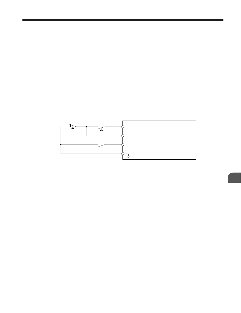
Figure 3.2 illustrates an example of a 3-Wire sequence.
Stop relay (N.C.)
Run relay (N.O.)
S1
Run command (run on momentary close)
S2
Stop command (stop on momentary open)
S5
Foward/reverse command
(multi-function input: H1-05 = 0)
SC
Sequence input common
Drive
Figure 3.2 3-Wire Sequence
YASKAWA ELECTRIC TOEP C710606 26D YASKAWA AC Drive – J1000 Quick Start Guide
Electrical Installation
3
41
Page 42
Drive
Jumper
Single-phase
200 Vac
Motor
DC link choke
(option)
Braking Resistor
Unit (option)
R/L1
S/L2
+1
+2
–
B1 B2
U/T1
V/T2
W/T3
—
Drive
Motor
Three phase 200 Vac
(400 Vac)
Braking
Resistor Unit
(option)
R/L1
S/L2
T/L3
U/T1
V/T2
W/T3
B1 B2
Jumper
DC link choke
(option)
+1
+2
3.3 Main Circuit Connection Diagram
3.3 Main Circuit Connection Diagram
Refer to diagrams in this section for the Main Circuit wiring connections. Connections may
vary based on drive capacity. The main circuit DC power supply powers the control circuit.
NOTICE: Do not use the negative DC bus terminal “-” as a ground terminal. This terminal is at high voltage
DC potential. Improper wiring connections could result in damage to the drive.
u
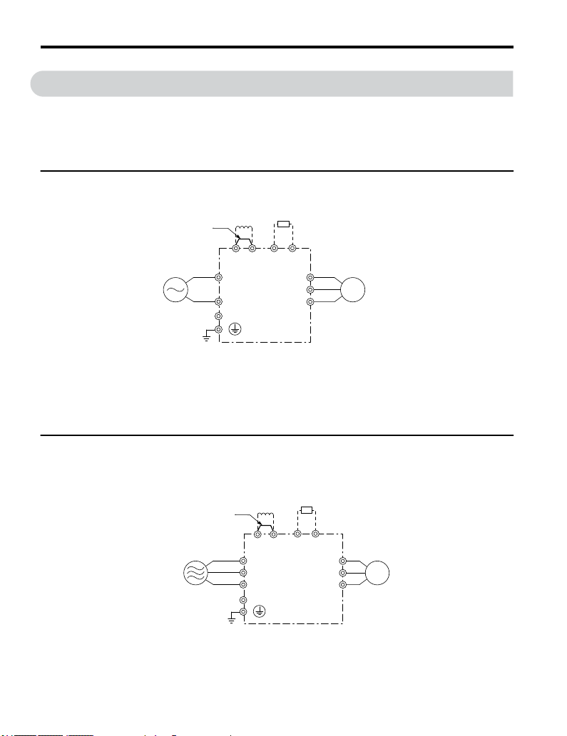
Single-Phase 200 V Class Models BA0001 to BA0010
Figure 3.3 Connecting Single-Phase Main Circuit Terminals
NOTICE: Do not connect T/L3 terminal when using single-phase power supply input. Incorrect wiring may
damage the drive.
u
Three-Phase 200 V Class Models 2A0001 to 2A0020 Three-Phase 400 V Class Models 4A0001 to 4A0011
42
Figure 3.4 Connecting Three-Phase Main Circuit Terminals
YASKAWA ELECTRIC TOEP C710606 26D YASKAWA AC Drive – J1000 Quick Start Guide
Page 43
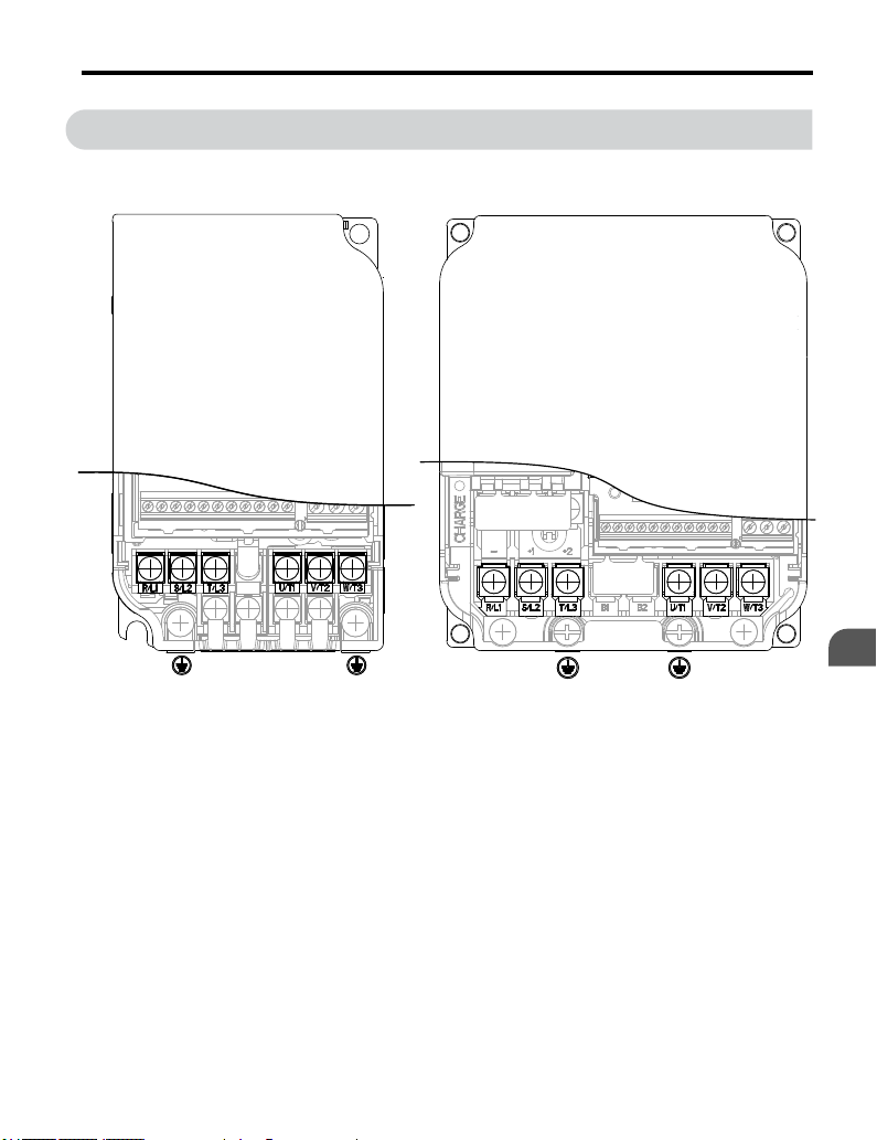
3.4 Terminal Block Configuration
3.4 Terminal Block Configuration
The figures in this section provide illustrations of the main circuit terminal block
configurations of the different drive sizes.
Models:
CIMR-JBA0001, 0002, 0003
CIMR-J2A0001, 0002, 0004, 0006
Figure 3.5 Main Circuit Terminal Block Configurations
Models:
CIMR-JBA0006, 0010
CIMR-J2A0010, 0012, 0020
CIMR-J4A0001, 0002, 0004, 0005, 0007,
0009, 0011
Electrical Installation
3
YASKAWA ELECTRIC TOEP C710606 26D YASKAWA AC Drive – J1000 Quick Start Guide
43
Page 44

3.5 Protective Covers
3.5 Protective Covers
Follow the procedure below to remove the protective covers before wiring the drive and to
reattach the covers after wiring is complete.
u
IP20/Open-Chassis Cover Removal and Installation
Removing the Protective Covers
n
Loosen the screw that locks the front cover in place to remove.
1.
Figure 3.6 Remove the Front Cover on an IP20/Open-Chassis Drive
pressure
Apply
2.
away from the drive while pushing in on the tabs to pull the cover free.
Figure 3.7 Remove the Terminal Cover on an IP20/Open-Chassis Drive
44
to the tabs on each side of the terminal cover. Pull the terminal cover
YASKAWA ELECTRIC TOEP C710606 26D YASKAWA AC Drive – J1000 Quick Start Guide
Page 45

3.5 Protective Covers
Reattaching the Protective Covers
n
Properly connect
all protective covers when wiring is complete. Apply only a small amount of pressure to lock
the cover back into place.
all wiring and route power wiring away from control signal wiring. Reattach
Figure 3.8 Reattach the Protective Covers on an IP20/Open-Chassis Drive
Electrical Installation
3
YASKAWA ELECTRIC TOEP C710606 26D YASKAWA AC Drive – J1000 Quick Start Guide
45
Page 46

3.6 Main Circuit Wiring
3.6 Main Circuit Wiring
This section describes the functions, specifications, and procedures required to safely and
properly wire the main circuit of the drive.
NOTICE: Do not solder the ends of wire connections to the drive. Soldered wiring connections can loosen
over time. Improper wiring practices could result in drive malfunction due to loose terminal connections.
u
Main Circuit Terminal Functions
Table 3.1 Main Circuit Terminal Functions
Terminal Type Function Reference
R/L1
T/L3
U/T1
W/T3
B1
B2
⊕1
⊕2
⊕1
⊖
(2 terminals)
Main circuit power
supply input
Drive output Connects to the motor. 49V/T2
Braking resistor
DC link choke
connection
DC power supply
input
Ground Grounding Terminal 49
Connects line power to the drive.
Drives with single-phase 200 V input power use terminals R/
L1 and S/L2 only.
Do NOT use T/L3.
Available for connecting a braking resistor or the braking
resistor unit option.
These terminals are shorted at shipment. Remove the shorting
bar between ⊕1 and ⊕2 when connecting a DC link choke to
this terminal.
For connecting a DC power supply. –
–S/L2
–
–
u
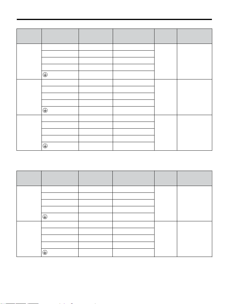
Wire Gauges and Tightening Torques
Select the appropriate wires and crimp terminals from Table 3.2 through Table 3.4.
Note: 1. Wire gauge recommendations based on drive continuous current ratings using 75 °C 600 Vac vinyl-
sheathed wire assuming ambient temperature within 30 °C and wiring distance shorter than 100 m.
2. Terminals ⊕1, ⊕2, ⊖, B1 and B2 are for connecting optional devices such as a braking resistor. Do
not connect other non-specified devices to these terminals.
• Consider the amount of voltage drop when selecting wire gauges. Increase the wire gauge
when the voltage drop is greater than 2% of motor rated voltage. Ensure the wire gauge is
suitable for the terminal block. Use the following formula to calculate the amount of voltage
drop:
•
Line drop voltage (V) = 3 x wire resistance (Ω/km) x
wire length (m) x current (A) x 10
• Refer to instruction manual TOBP C720600 00 for braking unit or braking resistor unit
wire gauges.
46
YASKAWA ELECTRIC TOEP C710606 26D YASKAWA AC Drive – J1000 Quick Start Guide
-3
Page 47

3.6 Main Circuit Wiring
• Refer to UL Standards Compliance on page 254
Single-Phase 200 V Class
n
Table 3.2 Wire Gauge and Torque Specifications
Drive
Model
BA0001
BA0002
BA0003
BA0006
BA0010
Three-Phase 200 V Class
n
Drive
Model
2A0001
2A0002
2A0004
2A0006
Terminal
R/L1, S/L2, T/L3 14 18 to 14
U/T1, V/T2, W/T3 14 18 to 14
⊖, ⊕1, ⊕2
B1, B2 – 18 to 14
R/L1, S/L2, T/L3 12 14 to 10
U/T1, V/T2, W/T3 14 14 to 10
⊖, ⊕1, ⊕2
B1, B2 – 14 to 10
R/L1, S/L2, T/L3 10 14 to 10
U/T1, V/T2, W/T3 14 14 to 10
⊖, ⊕1, ⊕2
B1, B2 – 14 to 10
Terminal
R/L1, S/L2, T/L3 14 18 to 14
U/T1, V/T2, W/T3 14 18 to 14
⊖, ⊕1, ⊕2
B1, B2 – 18 to 14
Recomm. Gauge
AWG, kcmil
– 18 to 14
14 18 to 14
– 14 to 10
10 14 to 10
– 14 to 10
10 14 to 10
Table 3.3 Wire Gauge and Torque Specifications
Recomm. Gauge
AWG, kcmil
– 18 to 14
14 18 to 14
for information on UL compliance.
Wire Range
AWG, kcmil
Wire Range
AWG, kcmil
Screw Size
M3.5
M4
M4
Screw Size
M3.5
Tightening
Torque
N•m (lb.in.)
0.8 to 1.0
(7.1 to 8.9)
1.2 to 1.5
(10.6 to 13.3)
1.2 to 1.5
(10.6 to 13.3)
Tightening
Torque
N•m (lb.in.)
0.8 to 1.0
(7.1 to 8.9)
Electrical Installation
3
YASKAWA ELECTRIC TOEP C710606 26D YASKAWA AC Drive – J1000 Quick Start Guide
47
Page 48
3.6 Main Circuit Wiring
Drive
Model
2A0010
2A0012
2A0020
Three-Phase 400 V Class
n
Terminal
R/L1, S/L2, T/L3 14 14 to 10
U/T1, V/T2, W/T3 14 14 to 10
⊖, ⊕1, ⊕2
B1, B2 – 14 to 10
R/L1, S/L2, T/L3 12 14 to 10
U/T1, V/T2, W/T3 14 14 to 10
⊖, ⊕1, ⊕2
B1, B2 – 14 to 10
R/L1, S/L2, T/L3 10 14 to 10
U/T1, V/T2, W/T3 10 14 to 10
⊖, ⊕1, ⊕2
B1, B2 – 14 to 10
Table 3.4 Wire Gauge and Torque Specifications
Drive
Model
4A0001
4A0002
4A0004
4A0005
4A0007
4A0009
Terminal
R/L1, S/L2, T/L3 14 14 to 10
U/T1, V/T2, W/T3 14 14 to 10
⊖, ⊕1, ⊕2
B1, B2 – 14 to 10
R/L1, S/L2, T/L3 14 14 to 10
U/T1, V/T2, W/T3 14 14 to 10
⊖, ⊕1, ⊕2
B1, B2 – 14 to 10
Recomm. Gauge
AWG, kcmil
– 14 to 10
10 14 to 10
– 14 to 10
10 14 to 10
– 14 to 10
10 14 to 10
Recomm. Gauge
AWG, kcmil
– 14 to 10
14 14 to 10
– 14 to 10
10 14 to 10
Wire Range
AWG, kcmil
Wire Range
AWG, kcmil
Screw Size
M4
M4
M4
Screw Size
M4
M4
Tightening
Torque
N•m (lb.in.)
1.2 to 1.5
(10.6 to 13.3)
1.2 to 1.5
(10.6 to 13.3)
1.2 to 1.5
(10.6 to 13.3)
Tightening
Torque
N•m (lb.in.)
1.2 to 1.5
(10.6 to 13.3)
1.2 to 1.5
(10.6 to 13.3)
48
YASKAWA ELECTRIC TOEP C710606 26D YASKAWA AC Drive – J1000 Quick Start Guide
Page 49

3.6 Main Circuit Wiring
Drive
Model
4A0011
u
Main Circuit Terminal Power Supply and Motor Wiring
This section
Terminal
R/L1, S/L2, T/L3 12 14 to 10
U/T1, V/T2, W/T3 14 14 to 10
⊖, ⊕1, ⊕2
B1, B2 – 14 to 10
outlines the various steps, precautions, and checkpoints for wiring the main circuit
Recomm. Gauge
AWG, kcmil
– 14 to 10
10 14 to 10
Wire Range
AWG, kcmil
Screw Size
M4
Tightening
Torque
N•m (lb.in.)
1.2 to 1.5
(10.6 to 13.3)
terminals and motor terminals.
NOTICE: When connecting the motor to the drive output terminals U/T1, V/T2, and W/T3, the phase order
for the drive and motor should match. Failure to comply with proper wiring practices may cause the motor to
run in reverse if the phase order is backward.
NOTICE: Route motor leads U/T1, V/T2, and W/T3 separate from all other leads to reduce possible
interference related issues. Failure to comply may result in abnormal operation of drive and nearby equipment.
NOTICE: Do not connect phase-advancing capacitors or LC/RC noise filters to the output circuits. Improper
application of noise filters could result in damage to the drive.
NOTICE: Do not connect the AC power line to the output motor terminals of the drive. Failure to comply could
result in death or serious injury by fire as a result of drive damage from line voltage application to output
terminals.
Cable Length Between Drive and Motor
n
When the cable length between the drive and the motor is too long (especially at low frequency
output), note that the cable voltage drop may cause reduced motor torque. Drive output current
will increase as the leakage current from the cable increases. An increase in leakage current
may trigger an overcurrent situation and weaken the accuracy of the current detection.
Adjust the drive carrier frequency according to the following table. If the motor wiring distance
exceeds 100 m because of the system configuration, reduce the ground currents.
Refer to Table 3.5 to set the carrier frequency to an appropriate level.
Table 3.5 Cable Length Between Drive and Motor
Cable Length 50 m or less 100 m or less Greater than 100 m
Carrier Frequency 15 kHz or less 5 kHz or less 2 kHz or less
Note: When setting
motors when running multiple motors from a single drive.
carrier frequency, calculate the cable length as the total distance of wiring to all connected
Electrical Installation
3
Ground Wiring
n
Follow the precautions to wire the ground for one drive or a series of drives.
YASKAWA ELECTRIC TOEP C710606 26D YASKAWA AC Drive – J1000 Quick Start Guide
49
Page 50

3.6 Main Circuit Wiring
WARNING! Electrical Shock Hazard. Always use a ground wire that complies with technical standards on
electrical equipment and minimize the length of the ground wire. Improper equipment grounding may cause
dangerous electrical potentials on equipment chassis, which could result in death or serious injury.
WARNING! Electrical Shock Hazard. Be sure to ground the drive ground terminal. (200 V Class: Ground to
100 Ω
or less, 400 V Class: Ground to 10 Ω or less). Improper equipment grounding could result in death or
serious injury by contacting ungrounded electrical equipment.
NOTICE: Do not share the ground wire with other devices such as welding machines or large-current electrical
equipment. Improper equipment grounding could result in drive or equipment malfunction due to electrical
interference.
NOTICE: When using more than one drive, ground multiple drives according to instructions. Improper
equipment grounding could result in abnormal operation of drive or equipment.
Refer to Figure 3.9 when using multiple drives. Do not loop the ground wire.
A
A – Correct B – Incorrect
Figure 3.9 Multiple Drive Wiring
B
50
YASKAWA ELECTRIC TOEP C710606 26D YASKAWA AC Drive – J1000 Quick Start Guide
Page 51

3.6 Main Circuit Wiring
Wiring the Main Circuit Terminal
n
WARNING! Electrical Shock Hazard. Shut off the power supply to the drive before wiring the main circuit
terminals. Failure to comply may result in death or serious injury.
Note: A cover
Main Circuit Connection Diagram
placed over the DC Bus and braking circuit terminals prior to shipment helps prevent miswiring.
Cut away covers as needed for terminals with a needle-nose pliers.
A
A – Protective Cover to Prevent Miswiring
Refer to section 3.3 Main Circuit Connection Diagram on page 42 for drive main power
circuit connections.
WARNING! Fire Hazard. The braking resistor connection terminals are B1 and B2. Do not connect braking
resistors to any other terminals. Improper wiring connections could cause the braking resistor to overheat
and cause death or serious injury by fire. Failure to comply may result in damage to the braking circuit or
drive.
Electrical Installation
3
YASKAWA ELECTRIC TOEP C710606 26D YASKAWA AC Drive – J1000 Quick Start Guide
51
Page 52

3.7 Control Circuit Wiring
3.7 Control Circuit Wiring
NOTICE: Do not
time. Improper wiring practices could result in drive malfunction due to loose terminal connections.
Main speed
frequency
reference.
Multi-function
programmable
solder the ends of wire connections to the drive. Soldered wire connections can loosen over
J1000
Control circuit
+
24 V 8 mA
<2>
DIP
switch S3
Shield ground
terminal
Setting power supply
+10.5 max. 20 mA
0 to +10 V (20 k )
(0)4 to 20 mA (250 )
main circuit terminal
Sink
Source
shielded line
Option unit
connector
DIP switch S1
I V
MA
MB
MC
24 V
AM
AC
twisted-pair shielded line
control terminal
Digital output
250 Vac, 10 mA to 1 A
30 Vdc, 10 mA to 1 A
(default setting)
<3>
Analog monitor
output
+
AM
0 to +10 Vdc
(2 mA)
-
Monitor
output
Forward run/stop
Reverse run/stop
External fault
Fault reset
Multi-step
speed 1
main/aux switch
Digital inputs
(default setting)
2 k
<1>
S1
S2
S3
S4
S5
SC
+V
A1
AC
Figure 3.10 Control Circuit Connection Diagram
<1> Connected using sequence input signal (S1 to S5) from NPN transistor; Default: sink
mode (0 V com)
Use
<2>
only the +24 V internal power supply in sinking mode; the source mode requires an
external power supply. Refer to I/O Connections on page 59.
52
YASKAWA ELECTRIC TOEP C710606 26D YASKAWA AC Drive – J1000 Quick Start Guide
Page 53

3.7 Control Circuit Wiring
<3> Minimum load: 5 Vdc, 10 mA (reference value).
u
Control Circuit Terminal Block Functions
Drive parameters
determine which functions apply to the multi-function digital inputs (S1 to
S5), multi-function digital outputs (MA, MB, MC), and multi-function analog output (AM).
The default is called out next to each terminal in Figure 3.10.
WARNING! Sudden Movement Hazard. Always check the operation and wiring of control circuits after being
wired. Operating a drive with untested control circuits could result in death or serious injury.
WARNING! Confirm the drive I/O signals and external sequence before starting test run. Failure to comply
may result in death or serious injury.
Input Terminals
n
Table 3.6 Control Circuit Input Terminals
Type No. Terminal Name (Function) Function (Signal Level) Default Setting
Multi-function input 1 (Closed: Forward
S1
run, Open: Stop)
Multi-function input 2 (Closed: Reverse
MultiFunction
Digital
Inputs
Main
Frequency
Reference
Input
S2
run, Open: Stop)
Multi-function input 3 (External fault
S3
(N.O.)
S4 Multi-function input 4 (Fault reset)
Multi-function input 5 (Multi-step speed
S5
reference 1)
Multi-function input common (Control
SC
common)
A1 Frequency reference
+V Analog input power supply +10.5 Vdc (max allowable current 20 mA)
AC Frequency reference common 0 Vdc
24 Vdc, 8 mA
Note: Drive preset to sinking mode. When using
source
(±10%) external power supply. Refer to Sinking/
Sourcing Mode Switch on page 59.
Sequence common
Input voltage or input current (Selected by DIP switch
S1 and H3-01) 0 to +10 Vdc (20 kΩ),
Resolution: 1/1000
4 to 20 mA (250 Ω) or 0 to 20 mA (250 Ω),
Resolution: 1/500
set DIP switch S3 to allow for a 24 Vdc
mode,
Electrical Installation
3
YASKAWA ELECTRIC TOEP C710606 26D YASKAWA AC Drive – J1000 Quick Start Guide
53
Page 54

3.7 Control Circuit Wiring
Output Terminals
n
Table 3.7 Control Circuit Output Terminals
Type No. Terminal Name (Function) Function (Signal Level) Default Setting
Multi-Function
Digital Output
Monitor Output
u
Terminal Configuration
MA N.O. output (fault)
MB N.C. output (fault)
MC Digital output common
AM Analog monitor output 0 to 10 Vdc (2 mA or less) Resolution: 1/256
AC Monitor common 0 V
Digital output
30
10 mA to 1 A; 250 Vac, 10 mA to 1 A
Vdc,
Minimum load: 5 Vdc, 10 mA (reference value)
S1 S2 S3 S4 S5 SC A1 +V AC AM AC
Figure 3.11 Control Circuit Terminal
54
YASKAWA ELECTRIC TOEP C710606 26D YASKAWA AC Drive – J1000 Quick Start Guide
MCMBMA
Page 55
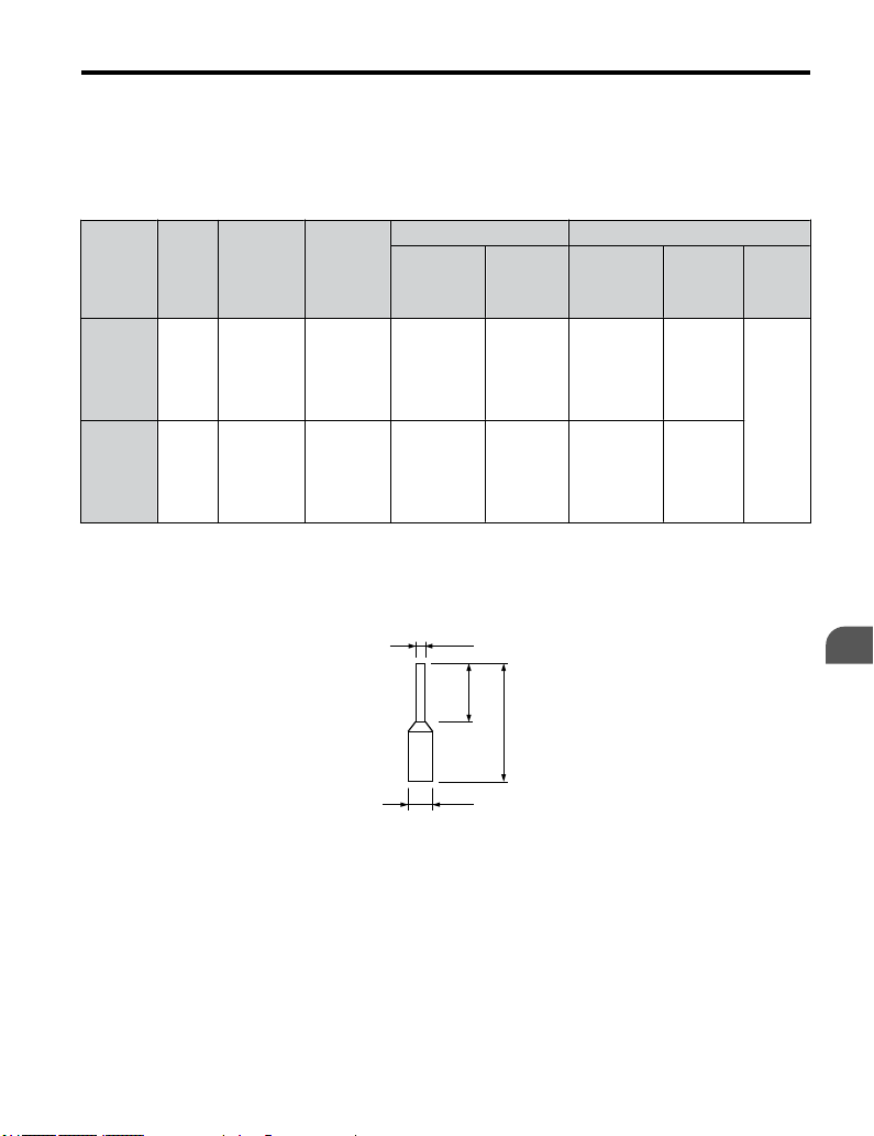
3.7 Control Circuit Wiring
Wire Size and Torque Specifications
n
Select appropriate wire type and size from Table 3.8. For simpler and more reliable wiring,
crimp ferrules to the wire ends. Refer to Table 3.9 for ferrule terminal types and sizes.
Table 3.8 Wire Size and Torque Specifications (Same for All Models)
Tightenin
Terminal
MA, MB,
MC
S1-S5,
SC, +V,
A1, AC,
AM
n
Crimp a
Screw
g Torque
Size
M3 0.5 to 0.6 4.4 to 5.3
M2 0.22 to 0.25 1.9 to 2.2
N•m
Ferrule-Type Wire Terminations
ferrule to signal wiring to improve wiring simplicity and reliability. Use CRIMPFOX
Tightenin
g Torque
(in-lbs)
Bare Wire Terminal Ferrule-Type Terminal
Applic.
wire size
2
mm
(AWG)
Stranded:
0.25 to 1.5
(24 to 16)
Single: 0.25
to 1.5
(24 to 16)
Stranded:
0.25 to 1.0
(24 to 18)
Single: 0.25
to 1.5
(24 to 16)
Recomm.
mm
(AWG)
0.75 (18)
0.75 (18)
2
Applic.
wire size
2
mm
(AWG)
0.25 to 1.0
(24 to 17)
0.25 to 0.5
(24 to 20)
Recomm.
2
mm
(AWG)
0.5 (20)
0.5 (20)
Wire
Type
Shielded
line, etc.
6, a crimping tool manufactured by PHOENIX CONTACT.
d1
Electrical Installation
3
6 mm
L
d2
Figure 3.12 Ferrule Dimensions
YASKAWA ELECTRIC TOEP C710606 26D YASKAWA AC Drive – J1000 Quick Start Guide
55
Page 56

3.7 Control Circuit Wiring
Table 3.9 Ferrule Terminal Types and Sizes
Size mm2 (AWG)
0.25 (24) AI 0.25-6YE 10.5 0.8 2.0
0.34 (22) AI 0.34-6TQ 10.5 0.8 2.0
0.5 (20) AI 0.5-6WH 12 1.1 2.5
0.75 (18) AI 0.75-6GY 12 1.3 2.8
1.0 AI 1-6RD 12 1.5 3.0
u
Wiring Procedure
This section
WARNING! Electrical Shock Hazard. Do not remove covers or touch the circuit boards while the power is on.
Failure to comply could result in death or serious injury.
NOTICE: Separate control circuit wiring from main circuit wiring (terminals R/L1, S/L2, T/L3, B1, B2, U/T1,
V/T2, W/T3, -, +1, +2) and other high-power lines. Improper wiring practices could result in drive malfunction
due to electrical interference.
NOTICE: Separate wiring for digital output terminals MA, MB and MC from wiring to other control circuit lines.
Improper wiring practices could result in drive or equipment malfunction or nuisance trips.
NOTICE: Use a class 2 power supply (UL standard) when connecting to the control terminals. Improper
application of peripheral devices could result in drive performance degradation due to improper power supply.
NOTICE: Insulate shields with tape or shrink tubing to prevent contact with other signal lines and equipment.
Improper wiring practices could result in drive or equipment malfunction due to short circuit.
NOTICE: Connect the shield of shielded cable to the appropriate ground terminal. Improper equipment
grounding could result in drive or equipment malfunction or nuisance trips.
describes the proper procedures and preparations for wiring the control terminals.
Type L (mm) d1 (mm) d2 (mm) Manufacturer
PHOENIX CONTACT
Wire the control terminals using Figure 3.13 as a guide. Prepare the ends of the control circuit
wiring as shown in Figure 3.14. Refer to Wire Size and Torque Specifications on page 55.
NOTICE: Do not tighten screws beyond the specified tightening torque. Failure to comply may damage the
terminal.
NOTICE: Use shielded twisted-pair cables as indicated to prevent operating faults. Improper wiring practices
could result in drive or equipment malfunction due to electrical interference.
Connect control wires as shown in the following figure:
56
YASKAWA ELECTRIC TOEP C710606 26D YASKAWA AC Drive – J1000 Quick Start Guide
Page 57

3.7 Control Circuit Wiring
D
Preparing wire
E
terminal ends
A
S1 S2 S3 S4 S5 SC A1 +V AC AM AC
C
A – Control terminal block
B – Avoid fraying wire
strands when stripping
insulation from wire.
Strip length 5.5 mm.
C – Single wire or stranded
wire
Figure 3.13 Terminal Board Wiring Guide
F
A
B
A – Drive side
B – Connect shield to ground
terminal of drive.
C – Insulation
Figure 3.14 Preparing the Ends of Shielded Cables
B
D – Loosen screw to insert
wire.
E – Blade depth of 0.4 mm or
less
Blade width of 2.5 mm or
less
C
E
D – Control device side
E – Shield sheath (Insulate
F – Shield
D
with tape)
Electrical Installation
3
When setting the frequency by analog reference from an external potentiometer, use shielded
twisted-pair wires and ground the shield of twisted-pair wires to the ground terminal of the
drive.
NOTICE: The analog
not exceed 50 meters when using an analog signal from a remote source to supply the frequency reference.
Failure to comply could result in poor system performance.
YASKAWA ELECTRIC TOEP C710606 26D YASKAWA AC Drive – J1000 Quick Start Guide
signal lines between the drive and the operator station or peripheral equipment should
57
Page 58
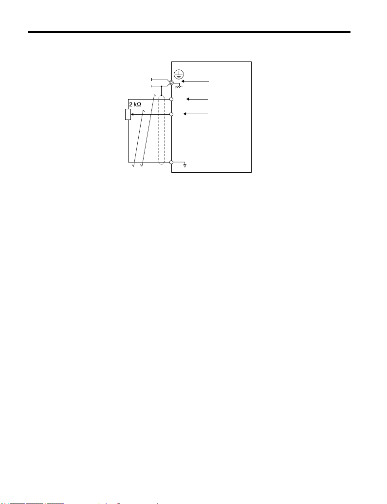
3.7 Control Circuit Wiring
A
B
+V
A1
AC
A – Drive
B –
Ground terminal (shield
connection)
Figure 3.15 Wiring the Frequency Reference to the Control Circuit Terminals (External
Reference)
C
D
C – (+V) Frequency setting
power source +10.5 Vdc
maximum 20 mA
D – (A1) Main speed
frequency reference 0 to
+10 Vdc (20 kΩ)
or
4 to 20 mA (250 Ω)/
0 to 20 mA (250 Ω)
58
YASKAWA ELECTRIC TOEP C710606 26D YASKAWA AC Drive – J1000 Quick Start Guide
Page 59
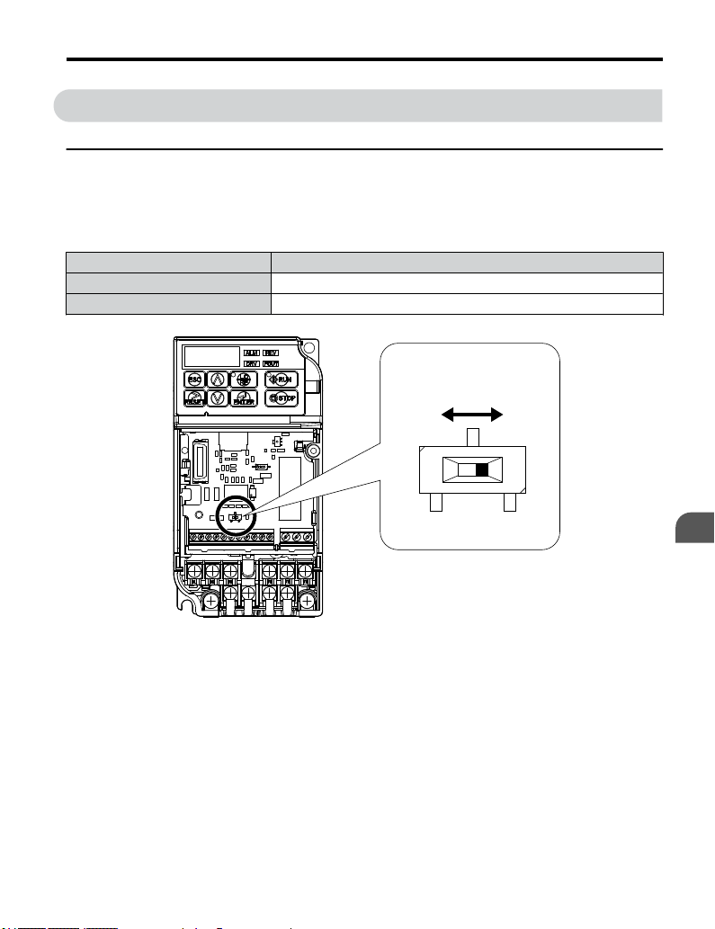
3.8 I/O Connections
3.8 I/O Connections
u
Sinking/Sourcing Mode Switch
Set the
DIP switch S3 on the front of the drive to switch the digital input terminal logic between
sinking mode and sourcing mode; the drive is preset to sinking mode.
Table 3.10 Sinking/Sourcing Mode Setting
Set Value Details
SINK Sinking Mode (0 V common): default setting
SOURCE Sourcing Mode (+24 V common)
DIP Switch S3
Electrical Installation
SOURCE
Figure 3.16 DIP Switch S3
YASKAWA ELECTRIC TOEP C710606 26D YASKAWA AC Drive – J1000 Quick Start Guide
SINK
3
59
Page 60

3.8 I/O Connections
Transistor Input Signal Using 0 V Common/Sink Mode
n
When controlling the digital inputs by NPN transistors (0 V common/sinking mode), set the
DIP switch S3 to SINK and use the internal 24 V power supply.
Shielded Cable
SOURCE
SINK
Multi-funciton input
FWD Run/Stop
REV Run/Stop
External Fault N.O.
Fault Reset
Multi-step Speed 1
Figure 3.17 Sinking Mode: Sequence from NPN Transistor (0 V Common)
S1
S2
S3
S4
S5
SC
S3
SINK
SOURCE
+24 V
60
YASKAWA ELECTRIC TOEP C710606 26D YASKAWA AC Drive – J1000 Quick Start Guide
Page 61
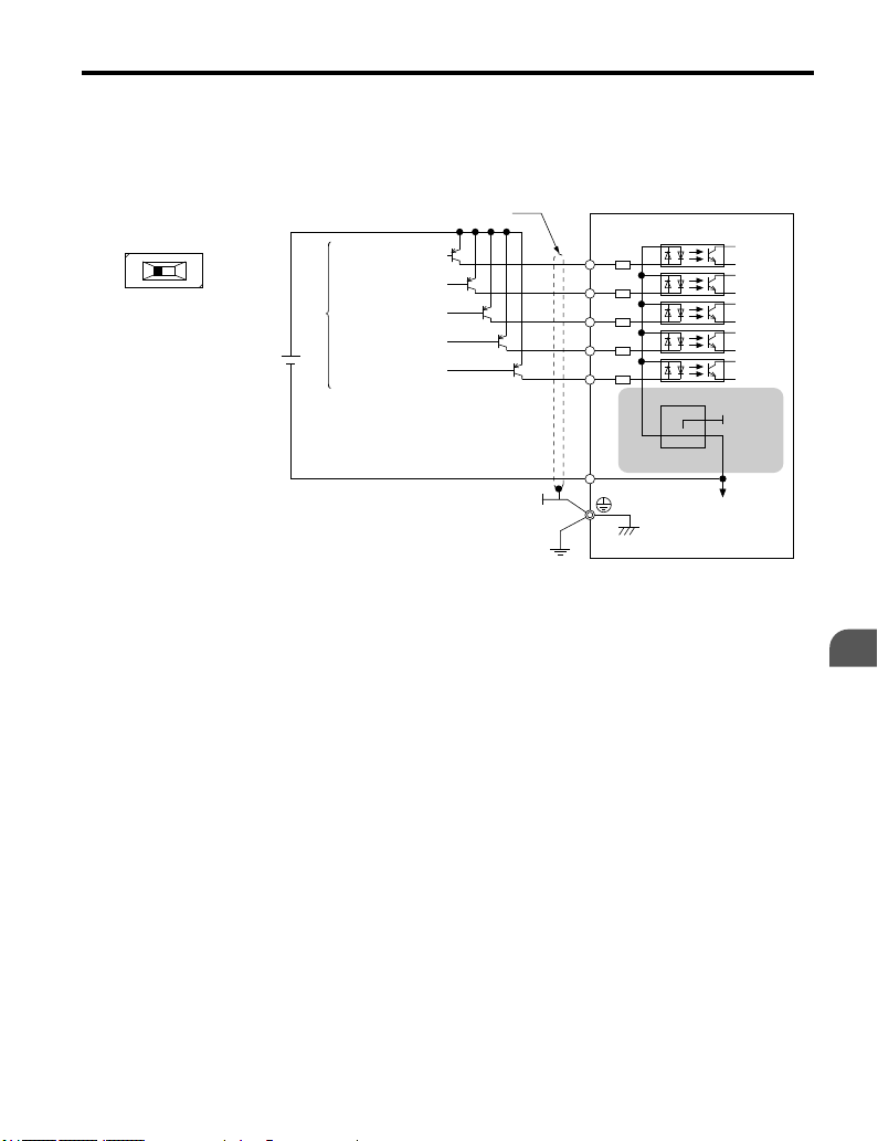
3.8 I/O Connections
Transistor Input Signal Using +24 V Common/Source Mode
n
When controlling digital inputs by PNP transistors (+24 V common/sourcing mode), set the
DIP switch S3 to SOURCE and use an external 24 V power supply.
Shielded cable
SOURCE
FWD Run/Stop
SINK
External
power supply
+24V
Figure 3.18 Source Mode: Sequence from PNP Transistor (+24 V Common)
REV Run/Stop
External Fault N.O.
Fault reset
Multi-step speed 1
S1
S2
S3
S4
S5
SC
SINK
S3
SOURCE
+24V
Electrical Installation
3
YASKAWA ELECTRIC TOEP C710606 26D YASKAWA AC Drive – J1000 Quick Start Guide
61
Page 62
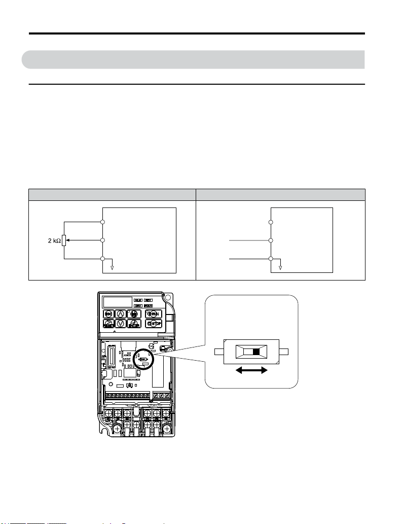
3.9 Main Frequency Reference
3.9 Main Frequency Reference
u
DIP Switch S1 Analog Input Signal Selection
The main frequency reference can either be a voltage or current signal input at terminal A1.
When using input A1 as a voltage input, set DIP switch S1 to “V” (right position, default
setting) and
Vdc without lower limit).
To use current input at terminal A1, set the DIP switch S1 to "I" and set parameter H3-01 =
“2” or “3” (4-20 mA or 0-20 mA).
program parameter H3-01 to “0” (0 to +10 Vdc with lower limit) or “1” (0 to +10
Table 3.11 Frequency Reference Configurations
Voltage Input Current Input
Drive
+10.5 V
+V
20 mA current
Main speed
A1
frequency reference
(current input)
AC
Frequency
reference
common
0 to 10 V
Drive
+10.5 V
+V
20 mA current
Main speed frequency
A1
reference (voltage input)
Frequency reference
AC
common
4 to 20 mA input
or
0 to 20 mA input
DIP Switch S1
I V
Figure 3.19 DIP Switch S1
62
YASKAWA ELECTRIC TOEP C710606 26D YASKAWA AC Drive – J1000 Quick Start Guide
Page 63
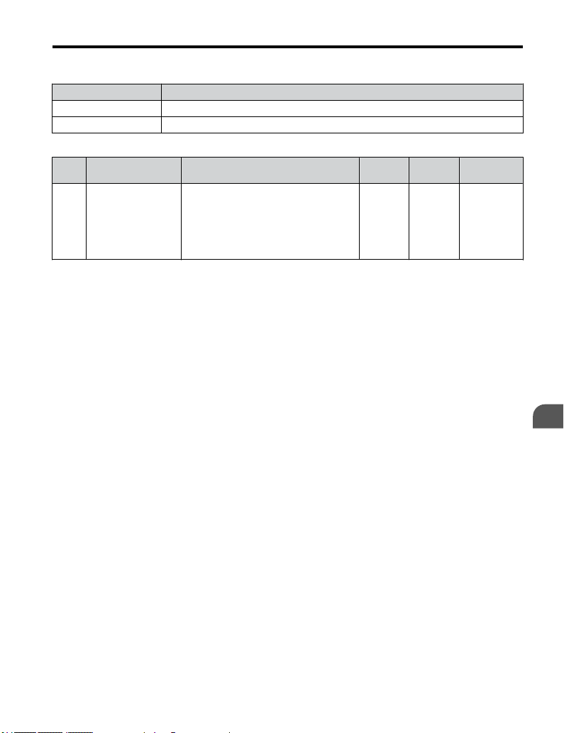
3.9 Main Frequency Reference
Table 3.12 DIP Switch S1 Settings
Setting Value Description
V ( right position) Voltage input (0 to 10 V): default setting
I ( left position) Current input (4 to 20 mA or 0 to 20 mA)
Table 3.13 Parameter H3-01 Details
No. Parameter Name Description
Selects the signal level for terminal A1.
0: 0 to +10 V, unipolar input (negative
frequency reference values are zeroed)
1: 0 to +10 V, bipolar input (negative
frequency reference changes the direction)
2: 4 to 20 mA
3: 0 to 20 mA
H3-01
Frequency ref.
(voltage/current)
terminal A1 signal
level selection
Setting
Range
0 to 3 0 410
Default
Setting
MEMOBUS
Register
Electrical Installation
3
YASKAWA ELECTRIC TOEP C710606 26D YASKAWA AC Drive – J1000 Quick Start Guide
63
Page 64

3.10 Braking Resistor
3.10 Braking Resistor
Dynamic braking
high inertia loads. Regeneration occurs as the drive lowers the motor frequency with high
inertia. When the regeneration flows back into the DC bus capacitors, an overvoltage situation
occurs. A braking resistor prevents these overvoltage faults.
NOTICE: Do not allow unqualified personnel to use the product. Failure to comply could result in damage to
the drive or braking circuit. Carefully review the braking resistor instruction manual when connecting a braking
option to the drive.
Note: The braking circuit must be sized properly in order to dissipate the power required to decelerate the load
NOTICE: Use a thermal overload relay or over-temperature contact to interrupt input power to the drive if the
braking resistor overheats. In the event of a possible thermal overload, the relay triggers the input contactor
and prevents the braking resistor from burning up.
u
Installation
WARNING! Fire Hazard.
resistor directly to any other terminals. Improper wiring connections could result in death or serious injury by
fire. Failure to comply may result in damage to the braking circuit or drive.
NOTICE: Connect braking resistors to the drive as shown in the I/O wiring examples. Improperly wiring braking
circuits could result in damage to the drive or equipment.
Installation Procedure
n
1.
2.
3.
(DB) helps bring the motor to a smooth and rapid stop when working with
in the desired time. Ensure that the braking circuit can dissipate the energy for the set deceleration time
prior to running the drive.
The braking resistor connection terminals are B1 and B2. Do not connect a braking
Disconnect all electrical power to the drive and wait at least one minute before
servicing the drive and any connected components.
Remove drive front cover.
Use a voltmeter to verify that voltage is disconnected from incoming power terminals
and that the DC bus no longer holds a charge.
64
YASKAWA ELECTRIC TOEP C710606 26D YASKAWA AC Drive – J1000 Quick Start Guide
Page 65

3.10 Braking Resistor
Thermal
relay
Power
supply
Thermal relay switch for
external braking resistor
MC
MA MC
MCCB
MCONMCOFFTHRX
SA
THRX
SA
TRX
SA
TRX
Fault contact
MC
B1 B2
R/L1
S/L2
T/L3
Drive
Figure 3.20 Connecting a Braking Resistor
Follow manufacturer instructions to connect the resistor unit to the drive using proper
4.
wire gauge according to local electrical codes.
Power leads for the remote mount resistors generate high levels of electrical noise;
group these signal leads separately.
Mount the resistor unit on a noncombustible surface. Maintain minimum side and top
5.
clearances according to resistor manufacturer instructions.
WARNING! Fire Hazard. Do not use improper combustible materials. Failure to comply could
result in death or serious injury by fire. Attach the drive or braking resistors to metal or other
noncombustible material.
Reinstall drive covers and resistor covers, if provided.
6.
Set parameter L3-04 = “0” to disable stall prevention during deceleration.
7.
Set parameter L8-01 to “1” to enable overheat protection when using a heatsinkmounted braking resistor option.
Set L8-01 = “0” for other braking resistor types.
Table 3.14 Braking Resistor Settings
Parameter Settings
L8-01: Internal Dynamic Braking
Resistor Protection Selection
L3-04: Stall Prevention During
Decel
Operate the system and verify the required deceleration rate is obtained during
8.
0: Disabled. The drive will not provide overheat protection.
Supply separate means of overheat protection.
1: Enabled. Braking Resistor is protected from overheat.
0: Stall prevention disabled.
dynamic braking or stopping.
U/T1
V/T2
W/T3
Braking resistor
Motor
Electrical Installation
3
YASKAWA ELECTRIC TOEP C710606 26D YASKAWA AC Drive – J1000 Quick Start Guide
65
Page 66

3.11 Interlocking with Connected Machinery
3.11 Interlocking with Connected Machinery
For safety
be set up so that operation can only occur when the drive is ready to operate. A "Drive ready"
and "Fault" signal should be assigned to the multi-function outputs to guarantee interlock with
application.
u
When the
output will close whenever the drive is ready to accept a Run command or is already running.
Under the following conditions the Drive ready signal will switch off and remain off, even if
a Run command is entered:
• when the power supply is shut off
• during a fault
• when there is problem with the control power supply
• when a parameter setting error makes the drive unable to run even if a Run command has
• when a fault such as overvoltage or undervoltage is triggered as soon as the Run command
• when the drive is in the Programming mode and will not accept a Run command even when
reasons, applications that may be affected by the operation status of the drive should
Drive Ready Signal
“Drive ready” signal has been set to one of the multi-function contact outputs, that
been entered
is entered
entered.
66
YASKAWA ELECTRIC TOEP C710606 26D YASKAWA AC Drive – J1000 Quick Start Guide
Page 67
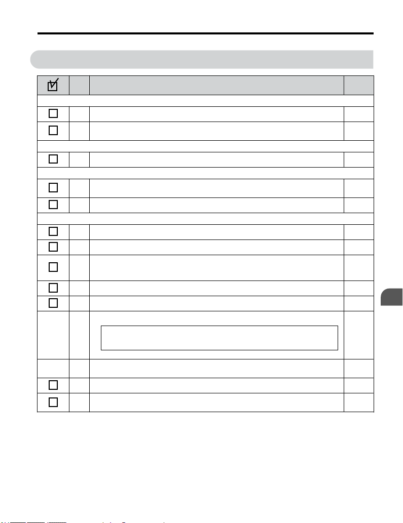
3.12 Wiring Checklist
No. Item Page
Drive, peripherals, option cards
1 Check drive model number to ensure receipt of correct model. 19
Check for correct braking resistors, DC link chokes, noise filters, and other peripheral
2
devices.
Installation area and physical setup
3 Ensure area surrounding the drive complies with specifications. 29
Power supply voltage, output voltage
The voltage from the power supply should fall within the input voltage specification range
4
of the drive.
5 The voltage rating for the motor should match the drive output specifications. 19
Main circuit wiring
6 Confirm proper branch circuit protection exists per National and Local codes. 39
7 Properly wire the power supply to drive terminals R/L1, S/L2 and T/L3. 42
Properly wire the drive and motor together. The motor lines and drive output terminals
8
R/T1, V/T2 and W/T3 should match in order to produce the desired phase order. If the
phase order is incorrect, the drive will rotate in the opposite direction.
9 Use 600 Vac vinyl-sheathed wire for the power supply and motor lines. 46
10 Use the correct wire gauges for the main circuit. Refer to Table 3.2 through Table 3.4. 46
• When using comparatively long motor cable, calculate the amount of voltage drop.
Motor rated voltage (V) x 0.02 ≥
3 x voltage resistance (Ω/km) x cable length (m) x motor rated current (A) x 10
3.12 Wiring Checklist
64
49
46
-3
Electrical Installation
3
YASKAWA ELECTRIC TOEP C710606 26D YASKAWA AC Drive – J1000 Quick Start Guide
• If the cable between the drive and motor exceeds 50 m, adjust the carrier frequency
(C6-02) accordingly.
11 Properly ground the drive. Review page 49. 49
Tightly fasten all terminal screws (control circuit terminals, grounding terminals). Refer
12
to Table 3.2 through Table 3.4..
49
46
67
Page 68

3.12 Wiring Checklist
No. Item Page
Set up overload protection circuits when running multiple motors from a single drive.
Power supply
13
Note: Close MC1 through MCn before operating the drive.
If using a braking resistor or dynamic braking resistor unit, install a magnetic contactor.
14
Properly install
15 Verify phase advancing capacitors are NOT installed on the output side of the drive. -
16 Use twisted-pair cables for all drive control circuit wiring. 52
17
Ground the shields of shielded wiring to the GND terminal.
If using a 3-Wire sequence, properly set parameters for multi-function contact input
18
terminals S1 through S5, and properly wire control circuits.
19 Check for any other wiring mistakes. Only use a multimeter to check wiring. -
Properly fasten the control circuit terminal screws in the drive. Refer to Table 3.2 through
20
Table 3.4.
21 Pick up all wire clippings. -
Ensure that no frayed wires on the terminal block are touching other terminals or
22
connections.
23 Properly separate control circuit wiring and main circuit wiring. -
24 Analog signal line wiring should not exceed 50 m. -
Drive
MC1 - MCn
OL
1 - OL
OL1
MC1
OL2
MC2
OLn
MCn
... magnetic contactor
n
... thermal relay
M1
M2
Mn
the resistor, and ensure that overload protection shuts off the power supply.
Control circuit wiring
-
64
56
41
46
-
68
YASKAWA ELECTRIC TOEP C710606 26D YASKAWA AC Drive – J1000 Quick Start Guide
Page 69

4
Start-Up
Programming &
Operation
This chapter explains the functions of the LED operator and how
to program the drive for initial operation.
4.1 SECTION SAFETY
4.2 USING THE DIGITAL LED OPERATOR..............73
4.3 THE DRIVE AND PROGRAMMING MODES.......79
4.4 START-UP FLOWCHART..................................87
4.5 BASIC OPERATION..........................................88
4.6 POWERING UP THE DRIVE.............................112
4.7 NO-LOAD OPERATION TEST RUN..................114
4.8 TEST RUN WITH LOAD CONNECTED.............116
4.9 VERIFYING AND BACKING UP PARAMETER
SETTINGS.......................................................117
4.10 TEST RUN CHECKLIST...................................119
YASKAWA ELECTRIC TOEP C710606 26D YASKAWA AC Drive – J1000 Quick Start Guide
.............................................70
69
Page 70

4.1 Section Safety
4.1 Section Safety
DANGER
Electrical Shock Hazard
Do not connect or disconnect wiring while the power is on.
Failure to comply will result in death or serious injury.
WARNING
Electrical Shock Hazard
Do not operate equipment with covers removed.
Failure to comply could result in death or serious injury.
The diagrams
details. Be sure to reinstall covers or shields before operating the drives and run the drives
according to the instructions described in this manual.
Always ground the motor-side grounding terminal.
Improper equipment grounding could result in death or serious injury by contacting the
motor case.
Do not touch any terminals before the capacitors have fully discharged.
Failure to comply could result in death or serious injury.
Before wiring terminals, disconnect all power to the equipment. The internal capacitor
remains charged even after the power supply is turned off. The charge indicator LED will
extinguish when the DC bus voltage is below 50 Vdc. To prevent electric shock, wait at
least one minute after all indicators are off and measure the DC bus voltage level to confirm
safe level.
Do not allow unqualified personnel to perform work on the drive.
Failure to comply could result in death or serious injury.
Installation, maintenance, inspection, and servicing must be performed only by authorized
personnel familiar with installation, adjustment and maintenance of AC drives.
in this section may include drives without covers or safety shields to illustrate
70
YASKAWA ELECTRIC TOEP C710606 26D YASKAWA AC Drive – J1000 Quick Start Guide
Page 71

4.1 Section Safety
WARNING
Do not perform work on the drive while wearing loose clothing, jewelry or without eye
protection.
Failure to comply could result in death or serious injury.
Remove all metal objects such as watches and rings, secure loose clothing, and wear eye
protection before beginning work on the drive.
Do not remove covers or touch circuit boards while the power is on.
Failure to comply could result in death or serious injury.
Fire Hazard
Tighten all terminal screws to the specified tightening torque.
Loose electrical
of electrical connections.
Do not use an improper voltage source.
Failure to comply could result in death or serious injury by fire.
Verify that the rated voltage of the drive matches the voltage of the incoming power supply
before applying power.
Do not use improper combustible materials.
Failure to comply could result in death or serious injury by fire.
Attach the drive to metal or other noncombustible material.
connections could result in death or serious injury by fire due to overheating
Start-Up Programming
& Operation
YASKAWA ELECTRIC TOEP C710606 26D YASKAWA AC Drive – J1000 Quick Start Guide
4
71
Page 72

4.1 Section Safety
NOTICE
Observe proper electrostatic discharge procedures (ESD) when handling the drive and
circuit boards.
Failure to comply may result in ESD damage to the drive circuitry.
Never connect or disconnect the motor from the drive while the drive is outputting
voltage.
Improper equipment sequencing could result in damage to the drive.
Do not use unshielded cable for control wiring.
Failure to comply may cause electrical interference resulting in poor system performance.
Use shielded twisted-pair wires and ground the shield to the ground terminal of the drive.
Do not allow unqualified personnel to use the product.
Failure to comply could result in damage to the drive or braking circuit.
Carefully review instruction manual TOBPC72060000 when connecting a braking option
to the drive.
Do not modify the drive circuitry.
Failure to comply could result in damage to the drive and will void warranty.
Yaskawa is not responsible for any modification of the product made by the user. This
product must not be modified.
Check
and connecting any other devices.
Failure to comply could result in damage to the drive.
the wiring to ensure that all connections are correct after installing the drive
all
72
YASKAWA ELECTRIC TOEP C710606 26D YASKAWA AC Drive – J1000 Quick Start Guide
Page 73

4.2 Using the Digital LED Operator
4.2 Using the Digital LED Operator
LED operator to enter run and stop commands, display data, edit parameters, as well
Use the
as display fault and alarm information.
u
Keys, Displays, and LEDs
1
2
3
J1000
:
1
:
2
周波数指令
:
3
正転逆転選択
:
4
出力周波数
:
5
出力電流
出力電圧
WARNING
Risk of electric shock.
Read manual before installing.
Wait 5 minutes for capacitor discharge after
disconnecting power supply.
To conform to requirements, make sure
to ground the supply neutral for 400V class.
けが、感電のおそれがあります。
危 険
据え付け、運転の前には必ず取扱説明書を読むこと。
分以内はフロントカバーを
通電中および電源遮断後
5
外さないこと。
級インバータの場合は、電源の中性点が接地
400V
されていることを確認すること。( 対応)
11
12
5
13
10
15
4
P
STOP
8
9
14
7
Start-Up Programming
& Operation
6
4
STOP
:
6
:
7
モニタ
8
:
ベリファイ
9
:
セットアップ
パラメータ設定
YASKAWA ELECTRIC TOEP C710606 26D YASKAWA AC Drive – J1000 Quick Start Guide
73
Page 74
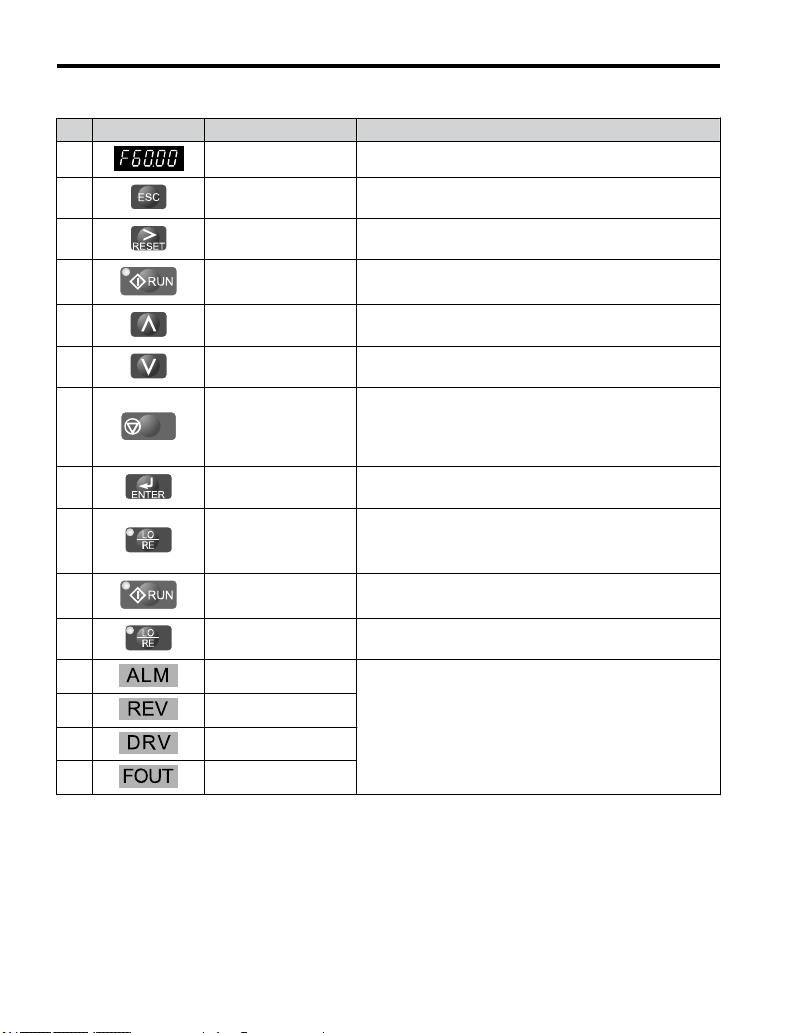
4.2 Using the Digital LED Operator
Table 4.1 Keys and Displays on the LED Operator
No. Display Name Function
1
2 ESC Key Returns to the previous menu.
Data Display Area Displays the frequency reference, parameter number, etc.
3
4
5 Up Arrow Key Scrolls up to select parameter numbers, setting values, etc.
6 Down Arrow Key Scrolls down to select parameter numbers, setting values, etc.
7
8
9
10 RUN Light Lit while the drive is operating the motor.
11
12 ALM LED Light
13
14 DRV LED Light
15 FOUT LED Light
STOP
RESET Key
RUN Key Starts the drive.
STOP Key
ENTER Key
LO/RE Selection Key
LO/RE Light Lit while the operator (LOCAL) is selected to run the drive.
REV LED Light
Moves the cursor to the right.
Resets the drive to clear a fault situation.
Stops the drive.
Note: Stop priority circuit. Pressing the STOP key will always
cause the drive to stop the motor, even if a Run command is
active at
any external Run command source. Set parameter o2-06
to 0 to disable the STOP key priority.
Selects all modes, parameters, settings, etc.
Selects a
menu item to move from one display screen to the next.
Switches drive control between the operator (LOCAL) and the
control circuit terminals (REMOTE).
Note: LOCAL/REMOTE key effective during stop in drive
mode.
Refer to LED Screen Displays on page 76.
74
YASKAWA ELECTRIC TOEP C710606 26D YASKAWA AC Drive – J1000 Quick Start Guide
Page 75
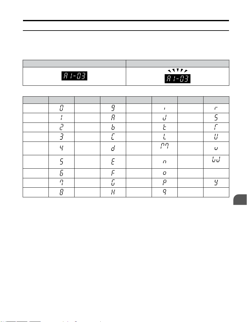
4.2 Using the Digital LED Operator
u
Digital Text Display
Text appears
on the LED Operator as shown below. This section explains the meaning of text
as it appears on the display screen.
Lit Flashing
Table 4.2 Digital Text Display
Text LED Text LED Text LED Text LED
0 9 I R
1 A J S
2 B K T
3 C L U
4 D M
5 E N W
6 F O X None
7 G P Y
8 H Q Z None
<1> Displayed in two digits.
YASKAWA ELECTRIC TOEP C710606 26D YASKAWA AC Drive – J1000 Quick Start Guide
<1>
V
<1>
Start-Up Programming
& Operation
4
75
Page 76

4.2 Using the Digital LED Operator
u
LED Screen Displays
Display Lit Flashing Off
When the drive detects an alarm
or error
Motor is rotating in reverse — Motor is rotating forward
Drive Mode — Programming Mode
Displays output frequency (Hz) — —
As illustrated
in this
manual
u
LO/RE LED and RUN LED Indications
• When an alarm occurs
•
oPE detected
Normal state (no fault or alarm)
LED Lit Flashing
When a Run command
is selected from the
LED operator
(LOCAL)
• During deceleration to
During Run
As shown
<1> Refer to Figure 4.1 for the difference between “flashing” and “flashing quickly”.
76
•
YASKAWA ELECTRIC TOEP C710606 26D YASKAWA AC Drive – J1000 Quick Start Guide
– –
stop
When a Run
command is input and
frequency reference is
0
Flashing Quickly
<1>
• During deceleration
at a fast-stop.
• During stop by
interlock operation.
Off
Run command is selected
from device other than LED
operator (REMOTE)
During stop
Page 77
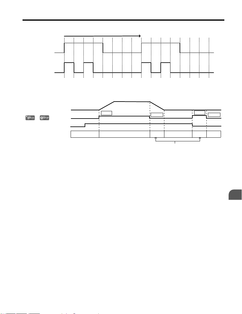
1 s
4.2 Using the Digital LED Operator
Flashing
Flashing
quickly
Drive output frequency
/
Frequency setting
RUN LED
ON
ON ON
Figure 4.1 RUN LED Status and Meaning
during stop
0 Hz
OFF
Figure 4.2 RUN LED and Drive Operation
RUN
6 Hz
ON
ON
ON ON
STOP
OFF
Flashing
RUN
STOP
OFF
Start-Up Programming
& Operation
4
YASKAWA ELECTRIC TOEP C710606 26D YASKAWA AC Drive – J1000 Quick Start Guide
77
Page 78
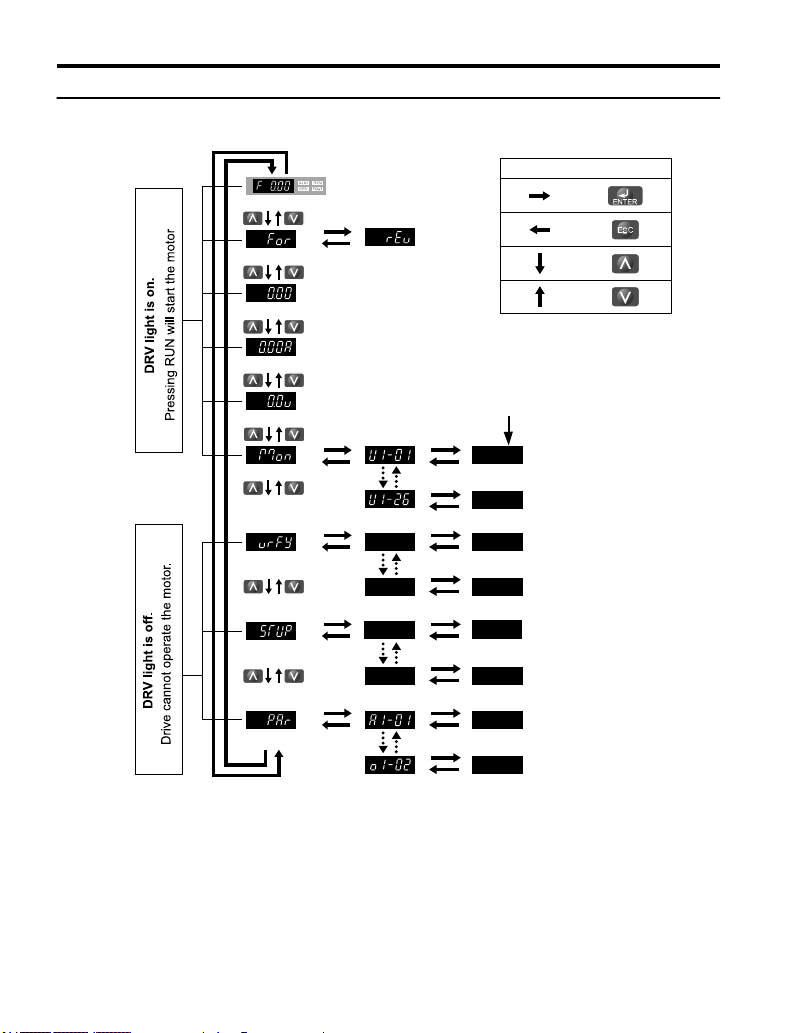
XXXX
XX
XX
XX
XX
XX
XX
XX
XX
XX
XX
XX
XX
XX
XX
:
:
:
:
Turn the power on
Forward Selection
Reverse Selection
Output Frequency
Output Current
Output Voltage
Monitor Display
Note: “XX” characters are shown in this manual.
The drive will display the actual setting values.
<1>
Verify Menu
Set Up Mode
Parameter Setting Mode
Description of Key Operations
PROGRAMMING MODE
DRIVE MODE
:
:
4.2 Using the Digital LED Operator
u
Menu Structure for Digital LED Operator
Figure 4.3 Digital LED Operator Screen Structure
<1> Reverse can only be selected when LOCAL is set.
78
YASKAWA ELECTRIC TOEP C710606 26D YASKAWA AC Drive – J1000 Quick Start Guide
Page 79
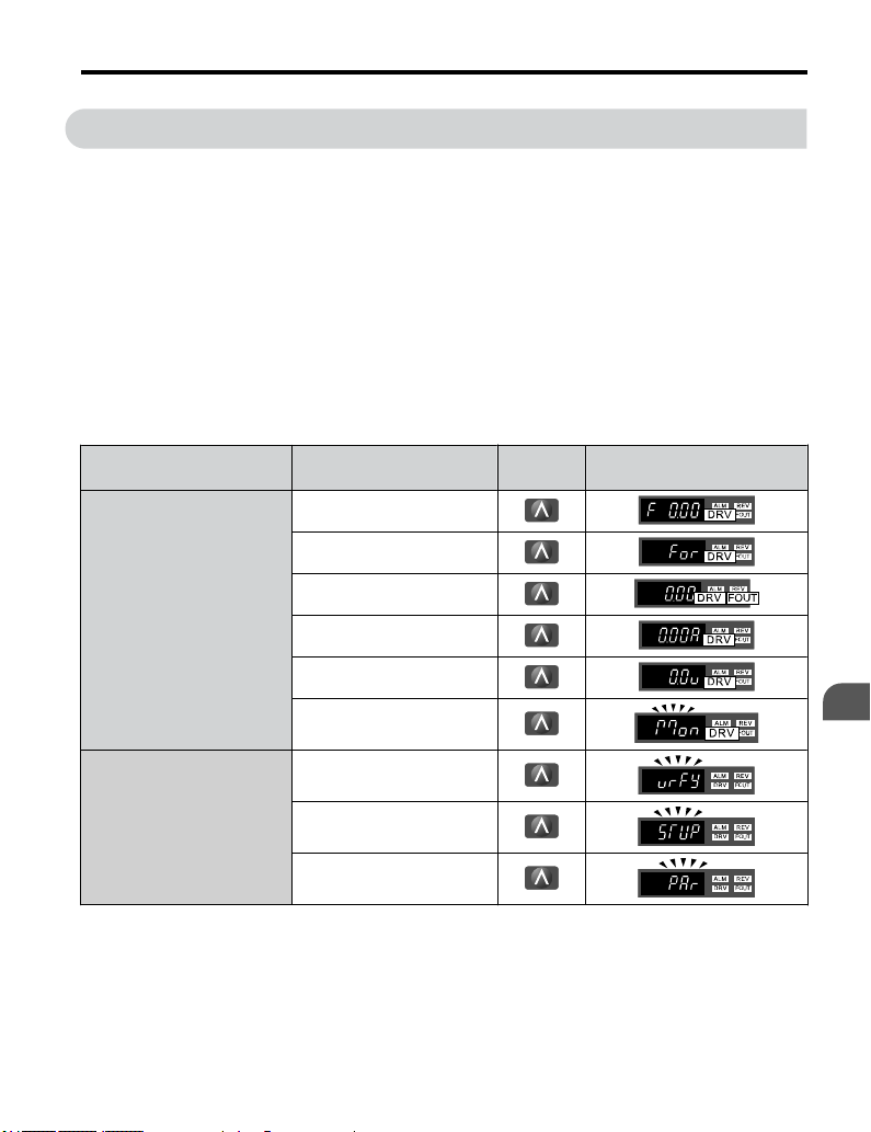
4.3 The Drive and Programming Modes
4.3 The Drive and Programming Modes
The drive
Drive Mode: The Drive mode allows motor operation and parameter monitoring. Parameter
settings cannot be changed when accessing functions in the Drive Mode (Table 4.3).
Programming Mode: The Programming Mode allows access to setup/adjust, verify
parameters. The drive prohibits changes in motor operation such as start/stop when the Digital
LED Operator is accessing a function in the Programming Mode.
Table 4.3 illustrates the different functions visible as the “Up arrow” is scrolled immediately
after powering up the drive.
functions are divided into two main groups accessible via the Digital LED Operator:
Note: When b1-08 (Run Command Selection while in Programming Mode) is set to 1 (enabled), the drive can
run even if the mode is switched to the programming mode. When setting b1-08 to 0 (disabled), the mode
cannot be switched to the programming mode while the drive is running.
Table 4.3 Summary of Modes
Mode Group Description Key Press
Frequency Reference Display
(Initial power-up state)
Forward/Reverse
LED Digital Operator Display
<1>
Drive Mode Functions
(Motor operation and
monitoring)
Programming Mode Functions
(Changing parameters)
<1> The enlarged illustration of the LED indicates that the LED is on.
YASKAWA ELECTRIC TOEP C710606 26D YASKAWA AC Drive – J1000 Quick Start Guide
Output Frequency Display
Output Current Display
Output Voltage Reference
Monitor Display
Verify Function
Setup Group Parameters
All Parameters
Start-Up Programming
& Operation
4
79
Page 80

4.3 The Drive and Programming Modes
u
Navigating the Drive and Programming Modes
The drive
screens using
is set to operate in Drive Mode when it is first powered up. Switch between display
and .
Frequency Reference
This display screen allows the user to monitor and set the frequency
Power Up
Default Setting
Forward/Reverse
Drive Mode
Output Frequency Display
reference while the drive is running. Refer to The Drive and
Programming Modes on page 79
Note: The user can select items to display when the drive is first
STOP
powered up by setting parameter o1-02.
: Motor rotates forward.
: Motor rotates in reverse.
Note: For applications that should not run in reverse (fans, pumps,
etc.), set
parameter b1-04 = “1” to prohibit the motor from rotating in
reverse. This sequence also puts the drive in LOCAL mode.
Switching to reverse:
The LED is lit when
LOCAL is selected
Monitors the frequency output by the drive.
.
Drive Mode
80
Output Current Display
YASKAWA ELECTRIC TOEP C710606 26D YASKAWA AC Drive – J1000 Quick Start Guide
Monitors the output current of the drive.
Page 81
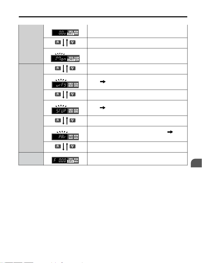
4.3 The Drive and Programming Modes
Output Voltage Reference
Drive Mode
Programming
Mode
Drive Mode
Drive Mode Details
n
Frequency Reference
Monitor Display
Verify Function
Setup
Parameter Setting
Monitors the output voltage of the drive.
Monitor parameters (U parameters) are displayed.
Lists all parameters that have been edited or changed from default
settings. Refer to Verifying Parameter Changes: Verify Menu
on page 84.
A select list of parameters necessary to get the drive operational
quickly. Refer to The Setup Group within the Programming
Mode on page 82.
Allows the user to access and edit all parameter settings. Refer
Parameter List
Returns to the frequency reference display screen.
on page 213.
The following actions are possible in the Drive Mode:
• Run and stop the drive.
•
Monitor the operation status of the drive (frequency reference, output frequency, output
current, output voltage, etc.).
• View information on an alarm.
Note: Select "Drive Mode" when running. The mode can be switched to any mode (program mode, etc.) other
than drive mode while the drive is stopped. However, the drive cannot be operated in other modes. Return
the mode to "Drive Mode" after completing periodic inspection.
Figure 4.4 illustrates changing the default frequency reference of F 0.00 (0 Hz) to F 6.00 (6
Hz) while in Drive Mode. This example assumes the drive is set to LOCAL.
to
Start-Up Programming
& Operation
4
YASKAWA ELECTRIC TOEP C710606 26D YASKAWA AC Drive – J1000 Quick Start Guide
81
Page 82

4.3 The Drive and Programming Modes
Frequency reference
display at power up
STOP
Press to select LOCAL
Press until the frequency
reference becomes 6 Hz
Figure 4.4 Setting the Frequency Reference while in Drive Mode
Note: The drive will not accept a frequency reference set value unless the ENTER key is pressed after the
n
frequency reference is entered. This feature prevents accidental setting of the frequency reference. By
setting o2-05 (Frequency Reference Setting Method Selection) to 1 (Enabled), the drive will accept the
frequency reference while it is being adjusted on the digital operator.
Programming Mode Details
Press to select the
digit to the right
The following actions are possible in the programming mode:
• Verify Function: Verify parameter setting changes from original default values.
• Setup Group: Access a list of commonly used parameters to simplify setup.
• Parameter Setting Mode: Access and edit all parameter settings.
The Setup Group within the Programming Mode
In Setup Group, the user can access the minimum group of parameters required to operate the
application.
Note: Setup Group parameters are listed in Table 4.4.
Figure 4.5 illustrates the keys to press to enter the Setup Group.
In this example, the source of the frequency reference is changed from the control circuit
terminals to the LED Operator (i.e., b1-01 is changed from 1 to 0).
82
YASKAWA ELECTRIC TOEP C710606 26D YASKAWA AC Drive – J1000 Quick Start Guide
Page 83

Frequency reference
appears when powered up
STOP
Press until
<1>
4.3 The Drive and Programming Modes
appears
Parameter Display
u
Changing Parameter Settings or Values
This example
explains changing C1-01 (Acceleration Time 1) from 10.0 seconds (default) to
Control Circuit
<1> Move to the right to change parameter settings. Scroll
down to view and check settings in the Setup Mode.
<2> To return to the Top Menu, press .
other parameters, press and .
Figure 4.5 Setup Group Example
Terminal
Select digit
to edit
20.0 seconds.
Step Display/Result
1. Turn on the power to the drive. The initial display appears.
<2>
Parameter Display
LED Operator
(2x)
To view or edit
Start-Up Programming
& Operation
4
2.
Press the key until the Setup Mode Screen appears.
YASKAWA ELECTRIC TOEP C710606 26D YASKAWA AC Drive – J1000 Quick Start Guide
83
Page 84

4.3 The Drive and Programming Modes
Step Display/Result
3.
Press the key to view the parameter setting display.
4.
Scroll through parameters by pressing the key until C1-01
appears.
5.
Press
farthest to the left flashes)
6.
Press
7.
Press the key and enter 0020.0.
8.
Press
9. The display automatically returns to the screen shown in Step 4.
10.
Press the key until back at the initial display.
u
Verifying Parameter Changes: Verify Menu
to view the current setting value (10.0). (Number
until the desired number is selected. (“1” flashes)
and the drive will confirm the change.
The Verify Menu lists edited parameters from the Programming Mode. The Verify Menu
helps determine
a drive. If no settings have been changed the Verify Menu will read
which settings have been changed, and is particularly useful when replacing
. The Verify menu
also allows users to access and re-edit edited parameters.
Note: The Verify Menu will not display parameters from the A1 group even if those parameters have been
changed from default settings.
The following example is a continuation of the steps beginning on page 83. Here, parameter
C1-01 is accessed using the Verify Menu and is changed again to 20.0 s.
To check the list of edited parameters:
Step Display/Result
1. Turn on the power to the drive. The initial display appears.
2.
Press until the display shows the “Verify” representation.
84
YASKAWA ELECTRIC TOEP C710606 26D YASKAWA AC Drive – J1000 Quick Start Guide
Page 85

4.3 The Drive and Programming Modes
Step Display/Result
Press
3.
from their original default settings.
Scroll through the list by pressing the key.
4.
Press the key until C1-01 appears.
5.
Press the key to access the setting value. (number farthest
to the left flashes)
u
Switching Between LOCAL and REMOTE
to enter the list of parameters that have been edited
Entering the run command using the LED operator is referred to as LOCAL, while entering
the run
command from an external device via the control circuit terminals or network option
is referred to as REMOTE.
WARNING! Sudden Movement Hazard. The drive may start unexpectedly if the Run command is already
applied when switching from LOCAL mode to REMOTE mode when b1-07 = 1, resulting in death or serious
injury. Be sure all personnel are clear of rotating machinery and electrical connections prior to switching
between LOCAL mode and REMOTE mode.
There are two ways to switch between LOCAL and REMOTE.
Note: 1. After selecting LOCAL, the LO/RE light will remain lit.
2. The drive will not allow the user to switch between LOCAL and REMOTE during run.
Using the LO/RE Key on the LED Operator
n
Step Display/Result
1. Turn on the power to the drive. The initial display appears.
Start-Up Programming
& Operation
4
Press . The LO/RE light will light up. The drive is now in
2.
Local.
the drive for REMOTE operation, press the
To set
YASKAWA ELECTRIC TOEP C710606 26D YASKAWA AC Drive – J1000 Quick Start Guide
key again.
STOP
85
Page 86

4.3 The Drive and Programming Modes
Using Input Terminals S1 through S5 to Switch between LO/RE
n
Switch between LOCAL and REMOTE using one of the digital input terminals S1 through
S5 (set the corresponding parameter H1-01 through H1-05 to “1”).
Follow the example below to set the digital input terminals.
Note: 1. For a list of digital input selections, Refer to Parameter List
u
n
Parameters used
2. Setting a multi-function input terminal to a value of 1 disables the LO/RE key on the LED operator.
Parameters Available in the Setup Group
Setup Mode (STUP)
for this drive are classified into A to U. To simplify the drive setup, frequently
on page 213.
used parameters are selected and input into Setup Mode.
To set a parameter, the Setup Mode must be displayed first. Press the Up/Down key
1.
until
Select the
2.
the Setup group. If the desired parameter cannot be set in the Setup mode, use the
Parameter Setting mode.
Parameter Name
b1-01 Frequency Reference Selection
b1-02 Run Command Selection
b1-03 Stop Method Selection
C1-01 Acceleration Time 1
C1-02 Deceleration Time 1
C6-01 Drive Duty Selection
C6-02 Carrier Frequency Selection
d1-01 Frequency Reference 1
d1-02 Frequency Reference 2
d1-03 Frequency Reference 3
d1-04 Frequency Reference 4
is displayed.
parameter and change the setting. Table 4.4 lists parameters available in
Table 4.4 Setup Group Parameters
Parameter Name
d1-17 Jog Frequency Reference
E1-01 Input Voltage Reference
E1-04 Maximum Output Frequency
E1-05 Maximum Voltage
E1-06 Base Frequency
E1-09 Minimum Output Frequency
E2-01 Motor Rated Current
H4-02 Terminal AM Gain Setting
L1-01 Motor Protection Function Selection
L3-04
Stall Prevention Selection during
Deceleration
86
YASKAWA ELECTRIC TOEP C710606 26D YASKAWA AC Drive – J1000 Quick Start Guide
Page 87

4.4 Start-up Flowchart
4.4 Start-up Flowchart
This section
as a quick reference to help familiarize the user with start-up procedures.
u
Figure 4.6 describes basic start-up sequence for the drive and motor system. This sequence
varies slightly depending on application. Use drive default parameter settings in simple
applications that do not require high precision.
summarizes the basic steps required to start the drive. The flowchart is intended
Flowchart: Basic Start-up
START
Install and wire the drive as explained in Chapters 1, 2 and 3
Adhere to safety messages concerning application of power.
Apply main power on to the drive.
* b1-01/02 for frequency reference and run command source selection
* H1-, H2-01, H3-, H4-, H5- for I/O terminal setting
* d1- for multi-speed references if used
* C1- and C2- for accel./decel. and S-curve time settings
* C6-01 for heavy/normal duty mode selection
* L3-04 if braking options are used
* E1-, V/f Characteristics
* E2-, Motor 1 parameters
Run the motor without load; check the rotation direction and operation.
Verify external signal commands to the drive work as desired.
Couple the load or machine to the motor. Run the machine and check for desired operation.
Fine tune parameters. Adjust application settings if necessary.
Check the machine operation and verify parameter settings.
YASKAWA ELECTRIC TOEP C710606 26D YASKAWA AC Drive – J1000 Quick Start Guide
Set the basic parameters:
Drive is ready to run the application.
Figure 4.6 Basic Start-Up
Start-Up Programming
& Operation
4
87
Page 88

4.5 Basic Operation
4.5 Basic Operation
This section explains the basic settings required for initial drive operation. Checking these
basic parameter settings during start-up will help to ensure a successful drive start-up.
If more information is required for parameters not listed in this section, Refer to Parameter
List on page 213
u
Initialize Parameter Values: A1-03
Parameter A1-03 (Initialize Parameters) resets all parameters to the original default values.
Note: Record all the changed settings before initializing parameters.
Different Methods of Drive initialization
n
2220: 2-Wire Initialization
Returns all
functions to input terminals S1 and S2.
3330: 3-Wire Initialization
Returns all parameters to factory default values for 3-wire control. A 3-Wire sequence assigns
functions to input terminals S1, S2, and S5.
u
Frequency Reference Source: b1-01
This section
be used to select the source of the run command and the frequency reference independently
(e.g., set the reference from the operator and set the run command from the terminals).
as required for a complete listing of drive parameters.
parameters to factory default values for 2-wire control. A 2-Wire sequence assigns
explains how to assign the frequency reference. Parameters b1-01 and b1-02 can
Frequency Reference from the LED Operator: b1-01 = 0
n
When b1-01 = 0 the frequency reference will be provided by the LED operator. Refer to The
Drive and Programming Modes on page 79 for information on how to set the frequency
reference.
Frequency Reference from the Analog Input Terminal: b1-01 = 1
n
When b1-01 = 1, analog input A1 provides the frequency reference.
Note: Set H3-01 (Terminal A1 Function Selection) to “0” to configure Terminal A1 for the main analog
Voltage Input
When entering the frequency reference with a voltage signal, set parameter H3-01 to “0” for
0 to 10 Vdc with lower reference limit. Set H3-01 to “1” if 0 to 10 Vdc input without lower
limit is required. Set DIP Switch S1 for voltage input (position “V”).
88
frequency reference.
YASKAWA ELECTRIC TOEP C710606 26D YASKAWA AC Drive – J1000 Quick Start Guide
Page 89

DIP switch S1
I V
4.5 Basic Operation
Drive
0 to 10 V
Main frequency
A1
(voltage or current input)
Analog common
AC
Figure 4.7 Voltage Input for the Frequency Reference
Current Input
When entering the frequency reference using an analog input signal, set parameter H3-01 to
“2” if 4 to 20 mA input is used. When using 0 to 20 mA input, set H3-01 to “3”. Set DIP
Switch S1 for current input (position “I”).
DIP switch S1
I V
0 or 4 to 20 mA input
Figure 4.8 Current Input for the Frequency Reference
Drive
V (+10.5 V, 20 mA power supply)
Main Frequency
A1
(current input)
Analog common
AC
Start-Up Programming
& Operation
4
YASKAWA ELECTRIC TOEP C710606 26D YASKAWA AC Drive – J1000 Quick Start Guide
89
Page 90
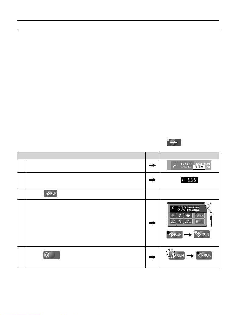
4.5 Basic Operation
u
Run Command Input Selection: b1-02
This section explains how to assign the run command input.
Parameters b1-01 and b1-02 can be used to select the source of the run command and the
frequency reference independently, e.g. set the reference from the operator and set the run
command from the terminals.
WARNING! Sudden Movement
circuitry before starting the drive. Failure to comply could result in death or serious injury from moving
equipment.
Run the Drive at 6 Hz using the LED Operator: b1-02 = 0
n
Hazard. Clear personnel, secure equipment, and check sequence and safety
To assign the run command to the operator panel, set parameter b1-02 to “0”. This will set up
the drive to acknowledge the run command through the LED operator. Initialize the run
command using the Run and Stop keys. Upon power up, the drive uses parameter b1-02 to
determine the run command location.
The following procedure indicates how to start and stop the drive through the LED operator
after parameter b1-02 has been set to 0.
Note:
1. Turn on the power to the drive. The initial display appears.
2.
3.
When b1-02 (Run Command Selection) is not set to 0 (operator), press
Step Display/Result
Set the frequency reference to F6.00 (6 Hz).
Note: Refer to
to set the frequency reference.
Press the
Drive Mode Details on page 81 for instructions on how
key to start the motor.
to set LOCAL.
4. The motor should accelerate up to 6 Hz while the RUN light is on.
5.
Press the
until the motor comes to a complete stop.
90
STOP
key to stop the motor. The RUN light will flash
YASKAWA ELECTRIC TOEP C710606 26D YASKAWA AC Drive – J1000 Quick Start Guide
off on
flashing
STOP
off
Page 91
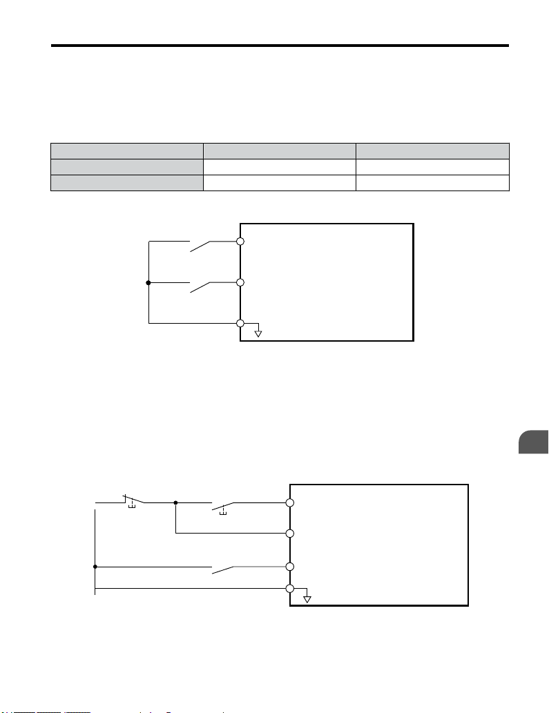
4.5 Basic Operation
Run the Drive using Digital Input Terminals: b1-02 = 1
n
This setting uses the digital input terminals to enter the run command. The factory setting is
a 2-Wire sequence.
Using a 2-Wire Sequence
Digital Input Terminals ON OFF
S1 Forward Run Stop
S2 Reverse Run Stop
Drive
Forward Run
S1
Reverse Run
Figure 4.9 Example Wiring Diagram for 2-Wire Sequence
S2
SC
Digital Input Common
Using a 3-Wire Sequence
When H1-05
(Multi-Function Digital Input Terminal S5 Function Selection) = 0, the functions
of terminals S1 and S2 are set to 3-Wire sequence, and the multi-function input terminal
becomes forward/reverse run command terminal.
Stop Button
(N.C.)
Figure 4.10 Example Wiring Diagram for 3-Wire Sequence Using Terminal S5
Run Button
(N.O.)
S1
Run Command
Runs when S1 and S2 are closed
(Run button pushed)
S2
Stop Command
Stops when S1 and S2 are open
(Stop button pushed)
S5
FWD/REV Command
SC
Drive
<1>
Digital Input Common
Start-Up Programming
& Operation
4
YASKAWA ELECTRIC TOEP C710606 26D YASKAWA AC Drive – J1000 Quick Start Guide
91
Page 92

4.5 Basic Operation
<1> When terminal S5 is open, the motor rotates forward. When closed, the motor rotates in
reverse.
WARNING! When 3-Wire sequence is used, set the drive to 3-Wire sequence before wiring the control
terminals and
If the drive is wired for 3-Wire sequence but set up for 2-Wire sequence (default) and if parameter b1-17 is
set to 1 (drive accepts a Run command at power up), the motor will rotate in reverse direction at power up of
the drive and may cause injury.
Note: Refer to Parameter List on page 213 for a list of digital input functions. After performing a 3-Wire
Note: Run by Turning on/off the Power Supply. For safety reasons, the drive is initially set up not to accept a
u
When a
n
ensure parameter b1-17 is set to 0 (drive does not accept a run command at power up (default)).
initialization (A1-03 = “3”), the drive will automatically assign the forward/reverse command to terminal
S5.
run command at power up (b1-17 = "0"). If a run command is issued at power up, the RUN indicator
LED will flash quickly. To change this and have the run command issued by the drive, change parameter
b1-17 to 1.
Stopping Method Selection: b1-03
Stop command is issued, the drive stops the motor using one of two possible methods.
Ramp to Stop: b1-03 = 0
When b1-03 = 0, the motor will decelerate to a stop when a stop command is entered. The
deceleration time is set by C1-02 (Deceleration Time 1). Refer to Acceleration/Deceleration:
C1-01 to C1-04 on page 93.
When the output frequency falls below E1-09 (Minimum Output Frequency) during
deceleration, the DC Injection braking current (b2-02) will be activated for the specified DC
Injection time at stop (b2-04).
Run Command
ON OFF
Output Frequency
DC Injection Braking
92
Decelerates according to the
specified deceleration time
Decel Time
(C1-02, etc.)
Figure 4.11 Ramp to Stop
YASKAWA ELECTRIC TOEP C710606 26D YASKAWA AC Drive – J1000 Quick Start Guide
DC Braking
Minimum Output Freq.
(E1-09)
DC Injection
Current (b2-02)
Time at Stop (b2-04)
Page 93
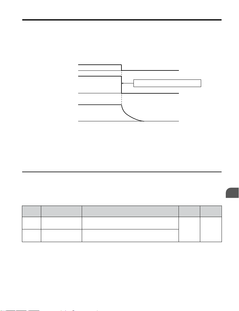
4.5 Basic Operation
Coast to Stop: b1-03 = 1
n
the run command is removed, the drive will shut off its output and the motor will coast
When
(uncontrolled deceleration). The motor will coast to a stop at the rate determined by the load
inertia.
Run Command
ON
OFF
Output Voltage
Drive output voltage interrupted
Motor Rotations
Figure 4.12 Coast to Stop
Note: 1. After entering a stop command, the drive will not accept another run command until the time set
u
Acceleration/Deceleration: C1-01 to C1-04
passes.
2. Do not enter another run command until the motor comes to a complete stop. If a run command must
be entered before the motor has fully stopped, use DC Injection to slow the motor or catch the motor
before restarting.
C1-01 (Acceleration Time 1) sets the time to accelerate from 0 to the maximum output
frequency (E1-04). C1-02 (Deceleration Time 1) sets the time to decelerate from maximum
output frequency to 0.
No. Parameter Name Description
C1-01
Acceleration Time 1
<1>
C1-02
Deceleration Time 1
<1>
<1> The parameter can be changed during run.
WARNING! Sudden Movement Hazard. Rapid deceleration may cause the drive to fault on an overvoltage
condition, resulting in death or serious injury due to an uncontrolled motor state. Set an acceptable
deceleration time in parameter C1-09 when using the Fast-stop feature.
Sets the time to accelerate from 0 to 100% (maximum
output frequency).
Sets the time to decelerate from 100% (maximum output
frequency) to 0%.
Setting
Range
0.0 to
6000.0
Default
10.0 s
Start-Up Programming
& Operation
4
YASKAWA ELECTRIC TOEP C710606 26D YASKAWA AC Drive – J1000 Quick Start Guide
93
Page 94
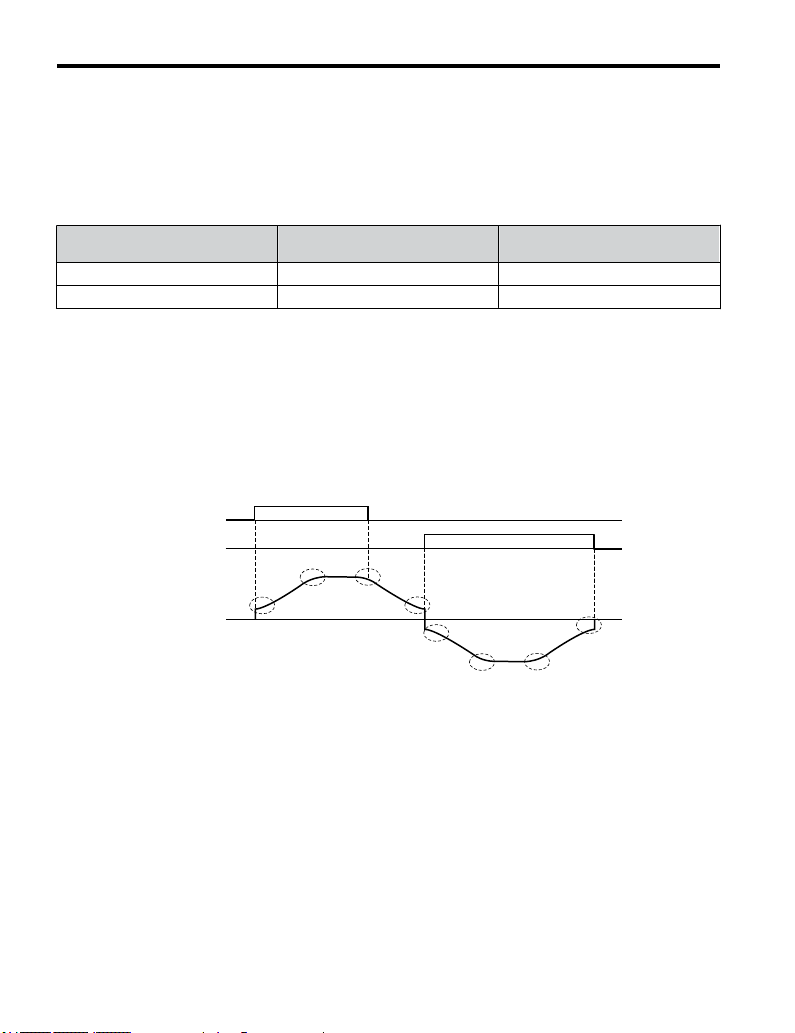
4.5 Basic Operation
Switching Accel/Decel Times with Digital Input Terminals
n
Two acceleration
/ deceleration times can be selected using one of the digital input terminals
S1 through S5.
Program one of the parameters H1-01 through H1-05 to “07” (Accel/Decel Time). Opening
or closing the digital input changes the accel/decel times as shown below:
Accel/Decel Time
H1- = 7
Open (not selected) C1-01 C1-02
Closed C1-03 C1-04
Using S-Curve Characteristics during Acceleration/Deceleration
n
Acceleration Time Deceleration Time
Use S-curve characteristics to smooth acceleration and deceleration and to minimize abrupt
shock to the load.
Note: Setting S-curve characteristics will lengthen accel/decel times as follows:
Setting Example
Accel Time = Selected Accel Time + (C2-01 + C2-02)/2
Decel Time = Selected Decel Time + (C2-03 + C2-04)/2
Figure 4.13 illustrates S-curve characteristics switching between forward and reverse.
Forward Run
Command
Reverse Run
Command
C2-03
C2-04
C2-01
C2-02
C2-04
C2-03
C2-02
Output
Frequency
94
C2-01
Figure 4.13 S-Curve Characteristics
YASKAWA ELECTRIC TOEP C710606 26D YASKAWA AC Drive – J1000 Quick Start Guide
Page 95
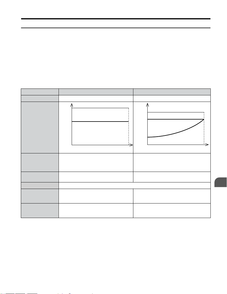
4.5 Basic Operation
u
Drive Duty and Carrier Frequency Selection: C6-01 and C6-02
Drive Duty Selection: C6-01
n
The drive
has two different duty modes from which to select based on the load characteristics.
The drive rated current, overload capacity, and carrier frequency will change depending upon
the duty mode selection. Use parameter C6-01 (Duty Cycle) to select Heavy Duty (HD) or
Normal Duty (ND) for the application. The default setting is ND. Refer to Specifications on
page 199 for details about the rated current.
HD and ND Mode Selections
Mode HD Rating ND Rating
C6-01 0 1
150 %
100 %
Characteristics
Overload
Rated Load
120 %
100 %
Overload
Rated Load
0 Motor Speed
Application
Overload capability
(oL2)
C6-02 2.0 to 15.0 kHz (default depends on drive capacity)
L3-02 Stall
Prevention during
Acceleration
L3-06 Stall
Prevention during
Run
Note: 1. By selecting HD/ND, motor parameter E2 is changed to the value for the maximum applicable
YASKAWA ELECTRIC TOEP C710606 26D YASKAWA AC Drive – J1000 Quick Start Guide
Use HD Rating is designed applications
requiring a high overload tolerance with
constant load torque, like conveyors.
100% continuous, 150% of drive rated current
for 60 s
150% 120%
150% 120%
motor.
2. Swing PWM uses 2.0 kHz carrier frequency as a base. The application of special PWM patterns
keeps the audible noise of the motor low.
100 %
0
Use ND Rating for applications in which the
torque requirements
Examples include fans or pumps where a high
overload tolerance is not required.
100% continuous, 120% of drive rated current
for 60 s
Motor Speed
drop along with the speed.
100 %
Start-Up Programming
& Operation
4
95
Page 96

4.5 Basic Operation
Carrier Frequency Selection: C6-02
n
Fixed Carrier Frequencies
The carrier frequency can be set using parameter C6-02 as shown in table below.
Parameter Name Description Setting Range Default
1 : 2.0 kHz
2 : 5.0 kHz
C6-02
Note: Settings 7 through A for parameter C6-02 use a Swing PWM equivalent to a 2 kHz audible noise. This
Note: The upper limit for the carrier frequency is determined by drive capacity.
Carrier
frequency
function turns the motor noise into a less obtrusive white noise.
3 : 8.0 kHz
4 : 10.0 kHz
5 : 12.5 kHz
6 : 15.0 kHz
7: Swing PWM
F : User defined (C6-03 to C6-05)
1 to F
Depends on
drive size
Precautions when setting parameter C6-02:
Symptom Possible Solution
Speed and torque are unstable at low speeds.
Noise from the drive is affecting peripheral devices.
Excessive leakage current from the drive.
Wiring between the drive and motor is too long.
Motor acoustic noise is too loud. Increase the carrier frequency or use Swing PWM.
<1> The carrier frequency may need to be lowered if the motor cable is too long. Refer to the table below.
Wiring Distance Up to 50 m Up to 100 m Greater than 100 m
C6-02 (Carrier Frequency Selection) 1 to F (15 kHz) 1 to 2 (5 kHz), 7 1 (2 kHz), 7
<1>
Lower the carrier frequency.
Carrier Frequency Setting Error (oPE11)
A carrier frequency setup error (oPE11) will occur when carrier frequency gain (C6-05) is
greater than 6 and C6-03 < C6-04.
Note: Refer to
Carrier Frequency and Drive Overload Current Level
n
Troubleshooting without Fault Display on page 151 for information on operator errors (oPE).
The tables below show the drive output current depending on the carrier frequency settings.
The 2 kHz value is equal to the Normal Duty (C6-01 = 1) rated current, the 8/10 kHz value
is equal to the Heavy Duty rated current. The carrier frequency determines the output current
linearly. Use the data below to calculate output current values for carrier frequencies not listed
in the tables.
Note: In Heavy Duty mode the maximum rated output current is equal to the 8/10 kHz value, even if the carrier
96
frequency is reduced.
YASKAWA ELECTRIC TOEP C710606 26D YASKAWA AC Drive – J1000 Quick Start Guide
Page 97

4.5 Basic Operation
Table 4.5 Drives with Heavy Duty Default Carrier Frequency of 10 kHz
200 V Single Phase Units 200 V Three Phase Units
Drive
Model
BA0001 1.2 0.8 0.6 2A0001 1.2 0.8 0.6
BA0002 1.9 1.6 1.3 2A0002 1.9 1.6 1.3
BA0003 3.5 3.0 2.4 2A0004 3.5 3.0 2.4
BA0006 6.0 5.0 4.0 2A0006 6.0 5.0 4.0
200 V Single Phase Units 200 V Three Phase Units 400 V Three Phase Units
Drive
Model
BA0010
u
Select up
Rated Current [A]
2 kHz 8 kHz 15 kHz 2 kHz 8 kHz 15 kHz 2 kHz 8 kHz 15 kHz
9.6 8.0 6.4 — — — — 4A0001 1.2 1.2 0.7
—
— — — 2A0010 9.6 8.0 6.4 4A0002 2.1 1.8 1.1
—
— — — 2A0012 12.0 11.0 8.8 4A0004 4.1 3.4 2.0
— — — — — — — — 4A0005 5.4 4.8 2.9
— — — — 2A0020 19.6 17.5 14.0 4A0007 6.9 5.5 3.3
— — — — — — — — 4A0009 8.8 7.2 4.3
— — — —
Multi-Step Speed Operation (4-Step Speed)
to 9 preset references (including Jog reference) using two multi-function inputs S4
Rated Current [A]
2 kHz 10 kHz 15 kHz 2 kHz 10 kHz 15 kHz
Table 4.6 Drives with Heavy Duty Default Carrier Frequency of 8 kHz
Drive
Model
— — — — 4A0011 11.1 9.2 5.5
Drive
Model
Rated Current [A]
Rated Current [A]
Drive
Model
Rated Current [A]
and S5. Two multi-step references can be selected using two multi-function inputs as
illustrated in Figure 4.14.
Start-Up Programming
& Operation
4
Multi-Step Speed Operation Parameters
n
No. Name Description
d1-01 Frequency Reference 1 Frequency reference. o1-03 determines the units, with Hz as the default.
d1-02 Frequency Reference 2
d1-03 Frequency Reference 3
d1-04 Frequency Reference 4
YASKAWA ELECTRIC TOEP C710606 26D YASKAWA AC Drive – J1000 Quick Start Guide
Frequency reference when multi-function input “Multi-Step Speed Reference 1"
(H1- = 3) is on. Setting unit: set by o1-03.
Frequency reference when multi-function input “Multi-Step Speed Reference 2”
(H1- = 4) is on. Setting unit: set by o1-03.
Frequency reference when multi-function input “Multi-Step Speed Reference 1,
2" (H1- = 3 and 4) are both on. Setting unit: set by o1-03.
97
Page 98

4.5 Basic Operation
Digital Input
n
Terminal Parameter Setting Contents
S4 H1-04 4 Multi-Step Speed Reference 2
S5 H1-05 3 Multi-Step Speed Reference 1
Wiring Example
n
Set up external switches SW1 and SW2.
Three-Phase, 200 Vac
(400 Vac)
SW1
SW2
Figure 4.14 Control Terminals for 4 Multi-Step Speeds
R/L1
S/L2
T/L3
S4
S5
SC
Drive
U/T1
V/T2
W/T3
M
98
YASKAWA ELECTRIC TOEP C710606 26D YASKAWA AC Drive – J1000 Quick Start Guide
Page 99

Frequency
Reference
4.5 Basic Operation
Freq Ref 4
Freq Ref 3
Freq Ref 2
Freq Ref 1
Forward/Reverse Run/Stop
Multi-Step Speed 1
Multi-Step Speed 2
Figure 4.15 4-Step Speed Time Chart
Setting Procedure
n
Step Display/Result
1. Turn on the power to the drive. The initial display appears.
Set the frequencies listed below to the specified parameters:
1. d1-01 = 5 Hz: Step 1
2.
2. d1-02 = 20 Hz: Step 2
3. d1-03 = 50 Hz: Step 3
4. d1-04 = 60 Hz: Step 4
3.
Press the
4. turns on.
<1>
key until the initial display appears.
OFF
OFF
ON
ON
ON
ON
Start-Up Programming
& Operation
4
YASKAWA ELECTRIC TOEP C710606 26D YASKAWA AC Drive – J1000 Quick Start Guide
99
Page 100

4.5 Basic Operation
Step Display/Result
5.
Press
6.
Press to run the motor at 5 Hz. The RUN light will turn on.
to select LOCAL. The LO/RE light will turn on.
STOP
STOP
Off On
With SW1 closed, the drive runs the motor at Multi-Step Speed 2
7.
(20 Hz).
With SW1 open and SW2 closed, the drive runs the motor at
8.
Multi-Step 3 (50 Hz).
With both SW1 and SW2 closed, the drive runs the motor at
9.
Multi-Step 4 (60 Hz).
10.
STOP
Press
motor comes to a complete stop.
to stop the drive. The RUN light will flash until the
Flashing Off
<1> When the frequency reference is assigned to the LED operator (b1-01=0), the first step in a multi-step speed
sequence comes from d1-01.
Note: When
a run command is input from the control circuit terminal, the frequency reference value is selected
as follows:
When b1-01 = 0 and the run command is given, the drive uses the frequency set to d1-01.
When b1-01 = 1 and the run command is given, the drive uses the frequency reference value input to
analog control terminal A1.
STOP
100
YASKAWA ELECTRIC TOEP C710606 26D YASKAWA AC Drive – J1000 Quick Start Guide
 Loading...