

Page 1
iQpump Micro AC Drive
Compact Intelligent Pump Controller
Quick Start Guide
Type: CIMR-PW
Models:
To properly use the product, read this manual thoroughly and retain
for easy reference, inspection, and maintenance. Ensure the end user
receives this manual.
200 V Class, Single-Phase Input: 1 to 5 HP ND
200 V Class, Three-Phase Input: 1.5 to 25 HP ND
400 V Class, Three-Phase Input: 1 to 25 HP ND
MANUAL NO. TOEP YAIQPM 02B
Page 2

Copyright © 2014 YASKAWA ELECTRIC CORPORATION.
No part of this publication may be reproduced, stored in a retrieval system, or transmitted, in any form or by any means,
mechanical, electronic, photocopying, recording, or otherwise, without the prior written permission of Yaskawa. No patent
liability is assumed with respect to the use of the information contained herein. Moreover, because Yaskawa is constantly
striving to improve its high-quality products, the information contained in this manual is subject to change without notice.
Every precaution has been taken in the preparation of this manual. Yaskawa assumes no responsibility for errors or omissions.
Neither is any liability assumed for damages resulting from the use of the information contained in this publication.
Page 3

iQpump Micro AC Drive Simplex Quick Start Procedure
u
This procedure is a supplement to other documentation supplied with this equipment and guides the user in properly wiring
the iQpump and motor. It also shows the configuration for a simplex pump application.
WARNING! Read and adhere to all safety messages contained in this manual prior to performing this procedure. When installing the system
be sure to follow good wiring practices and all applicable codes. Ensure that the mounting of the various components are secure and that
the environment, such as extreme dampness, poor ventilation etc. will not cause system degradation. Please read this cheat sheet and
other documentation provided with the iQpump thoroughly before attempting any installation.
The setup procedure begins on the next page.
YASKAWA TOEP YAIQPM 02B YASKAWA AC Drive - iQpump Micro Quick Start Guide
3
Page 4

4
YASKAWA TOEP YAIQPM 02B YASKAWA AC Drive - iQpump Micro Quick Start Guide
Page 5

YASKAWA TOEP YAIQPM 02B YASKAWA AC Drive - iQpump Micro Quick Start Guide
5
Page 6

6
YASKAWA TOEP YAIQPM 02B YASKAWA AC Drive - iQpump Micro Quick Start Guide
Page 7
YASKAWA TOEP YAIQPM 02B YASKAWA AC Drive - iQpump Micro Quick Start Guide
7
Page 8
8
YASKAWA TOEP YAIQPM 02B YASKAWA AC Drive - iQpump Micro Quick Start Guide
Page 9

YASKAWA TOEP YAIQPM 02B YASKAWA AC Drive - iQpump Micro Quick Start Guide
9
Page 10

10
YASKAWA TOEP YAIQPM 02B YASKAWA AC Drive - iQpump Micro Quick Start Guide
Page 11

YASKAWA TOEP YAIQPM 02B YASKAWA AC Drive - iQpump Micro Quick Start Guide
11
Page 12

12
YASKAWA TOEP YAIQPM 02B YASKAWA AC Drive - iQpump Micro Quick Start Guide
Page 13

YASKAWA TOEP YAIQPM 02B YASKAWA AC Drive - iQpump Micro Quick Start Guide
13
Page 14

14
YASKAWA TOEP YAIQPM 02B YASKAWA AC Drive - iQpump Micro Quick Start Guide
Page 15

YASKAWA TOEP YAIQPM 02B YASKAWA AC Drive - iQpump Micro Quick Start Guide
15
Page 16
16
YASKAWA TOEP YAIQPM 02B YASKAWA AC Drive - iQpump Micro Quick Start Guide
Page 17

YASKAWA TOEP YAIQPM 02B YASKAWA AC Drive - iQpump Micro Quick Start Guide
17
Page 18

18
YASKAWA TOEP YAIQPM 02B YASKAWA AC Drive - iQpump Micro Quick Start Guide
Page 19

YASKAWA TOEP YAIQPM 02B YASKAWA AC Drive - iQpump Micro Quick Start Guide
19
Page 20

20
YASKAWA TOEP YAIQPM 02B YASKAWA AC Drive - iQpump Micro Quick Start Guide
Page 21
YASKAWA TOEP YAIQPM 02B YASKAWA AC Drive - iQpump Micro Quick Start Guide
21
Page 22

22
YASKAWA TOEP YAIQPM 02B YASKAWA AC Drive - iQpump Micro Quick Start Guide
Page 23

YASKAWA TOEP YAIQPM 02B YASKAWA AC Drive - iQpump Micro Quick Start Guide
23
Page 24

24
YASKAWA TOEP YAIQPM 02B YASKAWA AC Drive - iQpump Micro Quick Start Guide
Page 25
YASKAWA TOEP YAIQPM 02B YASKAWA AC Drive - iQpump Micro Quick Start Guide
25
Page 26

26
YASKAWA TOEP YAIQPM 02B YASKAWA AC Drive - iQpump Micro Quick Start Guide
Page 27

YASKAWA TOEP YAIQPM 02B YASKAWA AC Drive - iQpump Micro Quick Start Guide
27
Page 28

This Page Intentionally Blank
28
YASKAWA TOEP YAIQPM 02B YASKAWA AC Drive - iQpump Micro Quick Start Guide
Page 29

i
iQpump Micro Quick Start Guide
i.1 PREFACE...............................................................................................................30
i.2 RECEIVING............................................................................................................37
i.3 MECHANICAL INSTALLATION.............................................................................39
i.4 ELECTRICAL INSTALLATION..............................................................................42
i.5 MAIN CIRCUIT WIRING.........................................................................................46
i.6 START-UP PROGRAMMING AND OPERATION..................................................58
i.7 TROUBLESHOOTING............................................................................................78
i.8 DRIVE SPECIFICATIONS......................................................................................87
i.9 PARAMETER TABLE............................................................................................90
i.10 STANDARDS COMPLIANCE..............................................................................102
i.11 REVISION HISTORY............................................................................................106
YASKAWA TOEP YAIQPM 02B YASKAWA AC Drive - iQpump Micro Quick Start Guide
29
Page 30
Micro
AVERTISSEMENT
Lire le manuel avant l'installation.
Attendre 5 minutes apres la coupure de l'alimentation,
pour permettre la decharge des condensateurs.
WARNING
Read manual before installing.
Wait 5 minutes for capacitor discharge after
disconnecting power supply.
Risk of electric shock.
Risque de decharge
electrique.
i.1 Preface
i.1 Preface
Yaskawa manufactures products used as components in a wide variety of industrial systems and equipment. The selection and
application of Yaskawa products remain the responsibility of the equipment manufacturer or end user. Yaskawa accepts no
responsibility for the way its products are incorporated into the final system design. Under no circumstances should any
Yaskawa product be incorporated into any product or design as the exclusive or sole safety control. Without exception, all
controls should be designed to detect faults dynamically and fail safely under all circumstances. All systems or equipment
designed to incorporate a product manufactured by Yaskawa must be supplied to the end user with appropriate warnings and
instructions as to the safe use and operation of that part. Any warnings provided by Yaskawa must be promptly provided to
the end user. Yaskawa offers an express warranty only as to the quality of its products in conforming to standards and
specifications published in the Yaskawa manual. NO OTHER WARRANTY, EXPRESS OR IMPLIED, IS OFFERED.
Yaskawa assumes no liability for any personal injury, property damage, losses, or claims arising from misapplication of its
products.
This manual is designed to ensure correct and suitable application of drives. Read this manual before attempting to install,
operate, maintain, or inspect a drive and keep it in a safe, convenient location for future reference. Be sure you understand all
precautions and safety information before attempting application.
u
Applicable Documentation
The following manuals are available for iQpump Micro drives:
iQpump Micro Quick Start Procedure (TOEPYAIQPM01)
This sheet is packaged together with the drive and contains a step-by-step guide to enable the user to properly wire the drive
and motor and connect the 24 V power supply.
iQpump Micro AC Drive Quick Start Guide (TOEPYAIQPM02)
Read this guide first. This guide is packaged together with the product and contains basic information required to install and
wire the drive. It also gives an overview of fault diagnostics, maintenance, and parameter settings. The purpose of this guide
is to prepare the drive for basic operation. The most recent version of this manual is available for download on our
documentation website, www.yaskawa.com.
iQpump Micro AC Drive User Manual (TOEPYAIQPM03)
This manual provides detailed information on parameter settings, fault diagnostics, and drive functions. Use this manual to
expand drive functionality and to take advantage of higher performance features. The most recent version of this manual is
available for download on our documentation website, www.yaskawa.com.
u
Supplemental Safety Information
General Precautions
• The diagrams in this manual may be indicated without covers or safety shields to show details. Replace the covers or shields before
operating the drive and run the drive according to the instructions described in this manual.
• Any illustrations, photographs, or examples used in this manual are provided as examples only and may not apply to all products to
which this manual is applicable.
• The products and specifications described in this manual or the content and presentation of the manual may be changed without notice
to improve the product and/or the manual.
• When ordering a new copy of the manual due to damage or loss, contact your Yaskawa representative or the nearest Yaskawa sales
office and provide the manual number shown on the front cover.
• If nameplate becomes worn or damaged, order a replacement from your Yaskawa representative or the nearest Yaskawa sales office.
WARNING
Read and understand this manual before installing, operating or servicing this drive. The drive must be installed according
to this manual and local codes.
The following conventions are used to indicate safety messages in this manual. Failure to heed these messages could result
in serious or fatal injury or damage to the products or to related equipment and systems.
DANGER
Indicates a hazardous situation, which, if not avoided, will result in death or serious injury.
30
YASKAWA TOEP YAIQPM 02B YASKAWA AC Drive - iQpump Micro Quick Start Guide
Page 31

WARNING
Indicates a hazardous situation, which, if not avoided, could result in death or serious injury.
WARNING! may also be indicated by a bold key word embedded in the text followed by an italicized safety message.
CAUTION
Indicates a hazardous situation, which, if not avoided, could result in minor or moderate injury.
CAUTION! may also be indicated by a bold key word embedded in the text followed by an italicized safety message.
NOTICE
Indicates a property damage message.
NOTICE: may also be indicated by a bold key word embedded in the text followed by an italicized safety message.
u
Safety Messages
DANGER
i.1 Preface
Heed the safety messages in this manual.
Failure to comply will result in death or serious injury.
The operating company is responsible for any injuries or equipment damage resulting from failure to heed the warnings in
this manual.
Electrical Shock Hazard
Before servicing, disconnect all power to the equipment.
The internal capacitor remains charged even after the power supply is turned off. The charge indicator LED will extinguish
when the DC bus voltage is below 50 Vdc. To prevent electric shock, wait for at least the time specified on the warning label,
once all indicators are OFF, measure for unsafe voltages to confirm the drive is safe prior to servicing.
Failure to comply will result in death or serious injury.
WARNING
Sudden Movement Hazard
System may start unexpectedly upon application of power, resulting in death or serious injury.
Clear all personnel from the drive, motor and machine area before applying power. Secure covers, couplings, shaft keys and
machine loads before applying power to the drive.
Electrical Shock Hazard
Do not attempt to modify or alter the drive in any way not explained in this manual.
Failure to comply could result in death or serious injury.
Yaskawa is not responsible for any modification of the product made by the user. This product must not be modified.
Do not allow unqualified personnel to use equipment.
Failure to comply could result in death or serious injury.
Installation, maintenance, inspection, and service must be performed only by authorized personnel familiar with installation,
adjustment and maintenance of AC drives.
YASKAWA TOEP YAIQPM 02B YASKAWA AC Drive - iQpump Micro Quick Start Guide
31
Page 32

i.1 Preface
WARNING
Do not remove covers or touch circuit boards while the power is on.
Failure to comply could result in death or serious injury.
Make sure the protective earthing conductor complies with technical standards and local safety regulations.
Always use appropriate equipment for Ground Fault Circuit Interrupters (GFCIs).
The drive can cause a residual current with a DC component in the protective earthing conductor. Where a residual current
operated protective or monitoring device is used for protection in case of direct or indirect contact, always use a type B GFCI
according to IEC/EN 60755.
Fire Hazard
Do not use an improper voltage source.
Failure to comply could result in death or serious injury by fire.
Verify that the rated voltage of the drive matches the voltage of the incoming power supply before applying power.
Install adequate branch circuit protection according to applicable local codes and this Installation Manual. Failure
to comply could result in fire and damage to the drive or injury to personnel.
The device is suitable for use on a circuit capable of delivering not more than 100,000 RMS symmetrical amperes, 240 Vac
maximum (200 V class) and 480 Vac maximum (400 V class) when protected by branch circuit protection devices specified
in this document.
Crush Hazard
Do not use this drive in lifting applications without installing external safety circuitry to prevent accidental dropping
of the load.
The drive does not possess built-in load drop protection for lifting applications.
Failure to comply could result in death or serious injury from falling loads.
Install electrical and/or mechanical safety circuit mechanisms independent of drive circuitry.
CAUTION
Crush Hazard
Do not carry the drive by the front cover.
Failure to comply may result in minor or moderate injury from the main body of the drive falling.
NOTICE
Observe proper electrostatic discharge procedures (ESD) when handling the drive and circuit boards.
Failure to comply may result in ESD damage to the drive circuitry.
Do not perform a withstand voltage test on any part of the drive.
Failure to comply could result in damage to the sensitive devices within the drive.
Do not operate damaged equipment.
Failure to comply could result in further damage to the equipment.
Do not connect or operate any equipment with visible damage or missing parts.
32
YASKAWA TOEP YAIQPM 02B YASKAWA AC Drive - iQpump Micro Quick Start Guide
Page 33

i.1 Preface
NOTICE
If a fuse is blown or a Ground Fault Circuit Interrupter (GFCI) is tripped, check the wiring and the selection of the
peripheral devices.
Contact your supplier if the cause cannot be identified after checking the above.
Do not restart the drive immediately operate the peripheral devices if a fuse is blown or a GFCI is tripped.
Check the wiring and the selection of peripheral devices to identify the cause. Contact your supplier before restarting the
drive or the peripheral devices if the cause cannot be identified.
Do not expose the drive to halogen group disinfectants.
Failure to comply may cause damage to the electrical components in the drive.
Do not pack the drive in wooden materials that have been fumigated or sterilized.
Do not sterilize the entire package after the product is packed.
General Application Precautions
n
Selection
Installing a Reactor
Use an AC reactor or DC link choke in the following situations:
• to suppress harmonic current.
• to smooth peak current that results from capacitor switching.
• when the power supply is above 600 kVA.
• when the drive is running from a power supply system with thyristor converters.
4000
Power supply harmonics
reactor required
Power Supply
Capacity (kVA)
Drive Capacity
600
0
Drive Capacity (kVA)
Figure i.1 Installing a Reactor
Reactor
unnecessary
60 400
For specialized motors, make sure that the motor rated current is less than the rated output current for the drive.
When running more than one motor in parallel from a single drive, the capacity of the drive should be larger than [total motor
rated current × 1.1].
Starting Torque
The overload rating of the drive determines the starting and accelerating characteristics of the motor. Expect lower running
torque than when running the motor from line power. To get more starting torque, use a larger drive or increase both the motor
and drive capacity.
Emergency/Fast Stop
During a drive fault condition, a protective circuit is activated and drive output is shut off. The motor may coast to a stop or
attempt to decelerate depending on parameter settings. If the emergency/fast stop cannot stop the load as fast as desired, a
customer-supplied mechanical brake may be required. Test emergency stop circuitry before putting drive into operation.
Repetitive Starting/Stopping
n
Applications with frequent starts and stops often exceed 150% of their rated current values. Heat stress generated from
repetitive high current can shorten the life span of the IGBTs. The expected lifetime for the IGBTs is about 8 million start and
stop cycles with a 4 kHz carrier frequency and a 150% peak current.
YASKAWA TOEP YAIQPM 02B YASKAWA AC Drive - iQpump Micro Quick Start Guide
33
Page 34

i.1 Preface
Yaskawa recommends lowering the carrier frequency, particularly when audible noise is not a concern. The user can also
choose to reduce the load, increase the acceleration and deceleration times, or switch to a larger drive. This will help keep
peak current levels under 150%. Be sure to check the peak current levels when starting and stopping repeatedly during the
initial test run, and make adjustments accordingly.
Installation
n
Enclosure Panels
Keep the drive in a clean environment by installing the drive in an enclosure panel or selecting an installation area free of
airborne dust, lint, and oil mist. Be sure to leave the required space between drives to provide for cooling, and take proper
measures so the ambient temperature remains within allowable limits and keep flammable materials away from the drive.
Yaskawa offers protective designs for drives that must be used in areas subjected to oil mist and excessive vibration. Contact
Yaskawa or your Yaskawa agent for details.
Installation Direction
NOTICE: Install the drive upright as specified in the manual. Refer to Mechanical Installation on page 39 for more information on
installation. Failure to comply may damage the drive due to improper cooling.
Settings
n
Upper Limits
NOTICE: The drive is capable of running the motor up to 400 Hz. Be sure to set the upper limit for the frequency of the drive to prevent the
possible danger of accidentally operating equipment at higher than rated speed. The default setting for the maximum output frequency is
60 Hz.
Lower Limits
NOTICE: Many pumps have a minimum safe operating speed. Be sure to properly set the minimum pump speed in to protect the pump
from damage.
DC Injection Braking
NOTICE: Excessive current during DC Injection Braking and excessive duration of DC Injection Braking can cause motor overheat.
Acceleration/Deceleration Times
Acceleration and deceleration times are affected by the amount of torque generated by the motor, the load torque, and the
inertia moment. Set a longer accel/decel time when Stall Prevention is enabled. The accel/decel times are lengthened for as
long as the Stall Prevention function is in operation.
General Handling
n
Wiring Check
NOTICE: Do not connect power supply lines to output terminals U/T1, V/T2, or W/T3. Failure to comply will destroy the drive. Be sure to
perform a final check of all sequence wiring and other connections before turning on the power and also check for short circuits on the
control terminals, which may damage the drive.
Selecting a Circuit Breaker or Circuit Interrupter
Yaskawa recommends installing a Ground Fault Circuit Interrupter (GFCI) to the power supply side. The GFCI should be
designed for use with AC drives (e.g., Type B according to IEC 60755).
Select a Molded Case Circuit Breaker (MCCB) or GFCI with a rated current 1.5 to 2 times higher than the drive rated input
current to avoid nuisance trips caused by harmonics in the drive input current.
Magnetic Contactor Installation
NOTICE: To get the full performance life out of the electrolytic capacitors and circuit relays, refrain from switching the drive power supply
off and on more than once every 30 minutes. Frequent use can damage the drive. Use the drive to stop and start the motor.
Inspection and Maintenance
WARNING! Electrical Shock Hazard. Capacitors in the drive do not immediately discharge after shutting off the power. Wait for at least the
amount of time specified on the drive before touching any components after shutting off the power. Failure to comply may cause injury to
personnel from electrical shock.
WARNING! Burn Hazard. Because the heatsink can get very hot during operation, take proper precautions to prevent burns. When replacing
the cooling fan, shut off the power and wait at least 15 minutes to be sure that the heatsink has cooled down. Failure to comply may cause
burn injury to personnel.
Wiring
Yaskawa recommends using ring terminals on all drive models. UL/cUL approval requires the use of UL Listed closed-loop
crimp terminals when wiring the drive main circuit terminals. Use only the tools recommended by the terminal manufacturer
for crimping.
34
YASKAWA TOEP YAIQPM 02B YASKAWA AC Drive - iQpump Micro Quick Start Guide
Page 35

i.1 Preface
Transporting the Drive
NOTICE: Never steam clean the drive. During transport, keep the drive from coming into contact with salts, fluorine, bromine, phthalate
ester, and other such harmful chemicals.
u
Motor Application Precautions
Standard Induction Motors
n
Low Speed Range
The cooling fan of a standard motor is usually designed to sufficiently cool the motor at the rated speed. As the self-cooling
capability of such a motor reduces with the speed, applying full torque at low speed will possibly damage the motor. To prevent
motor damage from overheat, reduce the load torque as the motor slows. Figure i.2 shows the allowable load characteristics
for a Yaskawa standard motor. A motor designed specifically for operation with a drive should be used when 100% continuous
torque is needed at low speeds.
25% ED (or 15 min)
40% ED (or 20 min)
60% ED (or 40 min)
100
90
80
70
(%)
60
50
Continuous operation
Torque
3 6
Figure i.2 Allowable Load Characteristics for a Yaskawa Motor
20
Frequency (Hz)
60
Insulation Tolerance
NOTICE: Consider motor voltage tolerance levels and motor insulation in applications with an input voltage of over 440 V or particularly
long wiring distances.
High-Speed Operation
NOTICE: Problems may occur with the motor bearings and dynamic balance of the machine when operating a motor beyond its rated speed.
Contact the motor or machine manufacturer.
Torque Characteristics
Torque characteristics differ compared to operating the motor directly from line power. The user should have a full
understanding of the load torque characteristics for the application.
Vibration and Shock
The drive allows selection of high carrier PWM control and low carrier PWM. Selecting high carrier PWM can help reduce
motor oscillation (drive current derating may be required).
Take particular caution when adding a variable speed drive to an application running a motor from line power at a constant
speed. If resonance occurs, use shock absorbing mounts to the motor base and enable the Jump frequency selection to prevent
continuous operation in the resonant frequency range.
Audible Noise
The audible noise of the motor varies based on the carrier frequency setting. However, drive current derating may be required.
When using a high carrier frequency, audible noise from the motor is comparable to the motor noise generated when running
from line power.
Specialized Motors
n
Multi-Pole Motor
Because the rated current will differ from a standard motor, be sure to check the maximum current when selecting a drive.
Always stop the motor before switching between the number of motor poles. If a regen overvoltage (oV) fault occurs or if
overcurrent protection (oC) is triggered, the motor will coast to stop.
YASKAWA TOEP YAIQPM 02B YASKAWA AC Drive - iQpump Micro Quick Start Guide
35
Page 36

Micro
AVERTISSEMENT
Lire le manuel avant l'installation.
Attendre 5 minutes apres la coupure de l'alimentation,
pour permettre la decharge des condensateurs.
WARNING
Read manual before installing.
Wait 5 minutes for capacitor discharge after
disconnecting power supply.
Risk of electric shock.
Risque de decharge
electrique.
i.1 Preface
Submersible Motor
The rated current of a submersible motor is greater than that of a standard motor, so select the drive accordingly. Use a motor
cable large enough to avoid decreasing the maximum torque level from voltage drop caused by a long motor cable.
Explosion-Proof Motor
The motor and the drive must be tested together to be certified as explosion-proof. The drive is not designed for explosionproof areas.
Geared Motor
Make sure that the gear and the lubricant are rated for the desired speed range to avoid gear damage when operating at low
speeds or very high speeds. Consult with the manufacturer for applications that require operation outside the rated speed range
of the motor or gear box.
Single-Phase Motor
Variable speed drives are not designed to operate with single phase motors. Using capacitors to start the motor causes excessive
current to flow and can damage drive components. A split-phase start or a repulsion start can burn out the starter coils because
the internal centrifugal switch is not activated. The drive is for use with three-phase motors only.
Notes on Power Transmission Machinery
n
Installing an AC drive in machinery that was previously connected directly to the power supply will allow the machine to
operate at variable speeds. Continuous operation outside of the rated speeds can wear out lubrication material in gear boxes
and other power transmission parts. Make sure that lubrication is sufficient within the entire speed range to avoid machine
damage. Note that operation above the rated speed can increase the noise generated by the machine.
u
Drive Label Warning Example
Always heed the warning information listed in Figure i.3.
Figure i.3 Warning Information Example
u
Warranty Information
Restrictions
n
The drive is not designed or manufactured for use in devices or systems that may directly affect or threaten human lives or
health.
Customers who intend to use the product described in this manual for devices or systems relating to transportation, health
care, space aviation, atomic power, electric power, or in underwater applications must first contact their Yaskawa
representatives or the nearest Yaskawa sales office.
WARNING! Injury to Personnel. This product has been manufactured under strict quality-control guidelines. However, if this product is to
be installed in any location where failure of this product could involve or result in a life-and-death situation or loss of human life or in a facility
where failure may cause a serious accident or physical injury, safety devices must be installed to minimize the likelihood of any accident.
36
YASKAWA TOEP YAIQPM 02B YASKAWA AC Drive - iQpump Micro Quick Start Guide
Page 37

i.2 Receiving
IND.CONT.EQ.
7J48
PASS
:
: AC3PH 200-240V 50 / 60Hz 2.7A
: AC3PH 0-240V 0-400Hz 1.2A / 0.8A
: 0.6 kg
:
:
: E131457 IP20
MODEL
MAX APPLI. MOTOR : 0.75kW / 0.4kW REV : A
INPUT
OUTPUT
MASS
O / N
S / N
FILE NO
I
H
G
F
D
B
A
YASKAWA ELECTRIC CORPORATION MADE IN JAPAN
2-1 Kurosaki-shiroishi, Yahatanishi-Ku, Kitakyushu 806-0004 Japan
C
E
CIMR-PW
CIMR
-
PW 2 V 0010 F A A
Drive
iQpump
No.
Enclosure
Type <1>
Design
Revision
Order
No.
Customized
Specifications
V Standard model
F
IP20/NEMA
Type 1
No.
Environmental
Specification <2>
A Standard
Refer to the following tables
G
IP66/NEMA
Type 4X
No. Voltage Class
2
4
1-phase, 200-240 Vac
B
3-phase, 200-240 Vac
3-phase, 380-480 Vac
u
Model Number and Nameplate Check
Please perform the following tasks after receiving the drive:
• Inspect the drive for damage.
If the drive appears damaged upon receipt, contact the shipper immediately.
• Verify receipt of the correct model by checking the information on the nameplate.
• If you have received the wrong model or the drive does not function properly, contact your supplier.
u
Nameplate
i.2 Receiving
<1> Refer to Mechanical Installation on page 39 for differences regarding enclosure protection types and component
descriptions.
<2> Please contact Yaskawa for details regarding Environmental Specifications.
YASKAWA TOEP YAIQPM 02B YASKAWA AC Drive - iQpump Micro Quick Start Guide
A – Normal Duty Amps
B – Software version
C – Enclosure type
D –
Address
<1>
F – Lot number
G – Output specifications
H – Input specifications
I – AC drive model
E – Serial number
Figure i.4 Nameplate Information Example
<1> The address of the head office of Yaskawa Electric Corporation (responsible for product liability) is shown on the nameplate.
37
Page 38

i.2 Receiving
Single-Phase 200 V Class
n
Drive Model Max. Motor Capacity kW (HP) Rated Output Current A
BV0006 1.1 (1) 6.0
BV0010 2.2 (3) 9.6
BV0012 3.0 (3) 12.0
BV0018 3.7 (5) 17.5
Three-Phase 200 V Class
n
Drive Model Max. Motor Capacity kW (HP) Rated Output Current A
2V0006 1.1 (1.5) 6.0
2V0010 2.2 (3) 9.6
2V0012 3.0 (3) 12.0
2V0020 5.5 (5) 19.6
2V0030 7.5 (10) 30.0
2V0040 11 (10) 40.0
2V0056 15 (20) 56.0
2V0069 18.5 (25) 69.0
Three-Phase 400 V Class
n
Drive Model Max. Motor Capacity kW (HP) Rated Output Current A
4V0002 0.75 (1) 2.1
4V0004 1.5 (2) 4.1
4V0005 2.2 (3) 5.4
4V0007 3.0 (3) 6.9
4V0009 3.7 (5) 8.8
4V0011 5.5 (7.5) 11.1
4V0018 7.5 (10) 17.5
4V0023 11 (15) 23.0
4V0031 15 (20) 31.0
4V0038 18.5 (25) 38.0
38
YASKAWA TOEP YAIQPM 02B YASKAWA AC Drive - iQpump Micro Quick Start Guide
Page 39

i.3 Mechanical Installation
i.3 Mechanical Installation
This section outlines specifications, procedures, and environment for proper mechanical installation of the drive.
u
Installation Environment
To help prolong the optimum performance life of the drive, install the drive in the proper environment. Table i.1 describes
the appropriate environment for the drive.
Table i.1 Installation Environment
Environment Conditions
Installation Area Indoors
IP20/NEMA Type 1 enclosure: -10 °C to +40 °C (14 °F to 104 °F)
IP66/NEMA Type 4X enclosure: -10 °C to +40 °C (14 °F to 104 °F)
Ambient Temperature
Humidity 95% RH or less and free of condensation
Storage Temperature -20 °C to +60 °C (-4 °F to +104 °F)
Surrounding Area
Altitude Up to 1000 meters without derating; up to 3000 meters with output current, ambient temperature, and voltage derating.
Vibration
Orientation Install the drive vertically to maintain maximum cooling effects.
Drive reliability improves in environments without wide temperature fluctuations.
When using an enclosure panel, install a cooling fan or air conditioner in the area to ensure that the air temperature inside
the enclosure does not exceed the specified levels.
Do not allow ice to develop on the drive.
Install the drive in an area free from:
• oil mist and dust
• metal shavings, oil, water or other foreign materials
• radioactive materials
• combustible materials (e.g., wood)
• harmful gases and liquids
• excessive vibration
• chlorides
• direct sunlight
For IP66/NEMA Type 4X enclosure drives, install the drive in an environment suitable for IP66/NEMA Type 4X
enclosures:
• NEMA Type 4X – Enclosures constructed for either indoor or outdoor use to provide a degree of protection to personnel
against incidental contact with the enclosed equipment; to provide a degree of protection against falling dirt, rain, sleet,
snow, windblown dust, splashing water, hose-directed water, and corrosion; and that will be undamaged by the external
formation of ice on the enclosure.
• IP66 – Dust-tight enclosures to do not allow any dust to penetrate. The enclosure guards the drive against powerful
jetting water sprayed from any direction and is protected against access to hazardous parts with a wire.
10 to 20 Hz at 9.8 m/s
20 to 55 Hz at 5.9 m/s
2
2
NOTICE: Prevent foreign matter such as metal shavings or wire clippings from falling into the drive during installation and project
construction. Failure to comply could result in damage to the drive. Place a temporary cover over the top of the drive during installation.
Remove the temporary cover before startup, as the cover will reduce ventilation and cause the drive to overheat.
NOTICE: Avoid placing drive peripheral devices, transformers, or other electronics near the drive. Failure to comply could result in erroneous
operation. If such devices must be used in close proximity to the drive, take proper steps to shield the drive from noise.
u
Installation Orientation and Spacing
NOTICE: Install the drive upright as illustrated in Figure i.5. Failure to comply may damage the drive due to improper cooling.
Figure i.5 Correct Installation Orientation
YASKAWA TOEP YAIQPM 02B YASKAWA AC Drive - iQpump Micro Quick Start Guide
39
Page 40

A A
B
C
C
Top/Bottom Clearance
Side Clearance
2 mm
A
B
B
C
D
C
i.3 Mechanical Installation
Single Drive Installation
n
Figure i.6 shows the required installation spacing to maintain sufficient space for airflow and wiring for IP20/NEMA Type
1 and IP66/NEMA Type 4X enclosures. Install the heatsink against a closed surface to avoid diverting cooling air around the
heatsink.
A – 30 mm minimum
B – Airflow direction
Figure i.6 Correct Installation Spacing
Note: IP20/NEMA Type 1 and IP66/NEMA Type 4X enclosure models require the same amount of space above and below the drive for installation.
Multiple Drive Installation
n
C – 100 mm minimum
When installing multiple drives into the same enclosure panel, mount the drives according to Figure i.6. When mounting
drives with a minimum side-by-side clearance of 2 mm according to Figure i.7, derating must be considered and parameter
L8-35 must be set.
A – Line up the tops of the drives.
B – 30 mm minimum
Figure i.7 Space Between Drives (Side-by-Side Mounting)
C – 100 mm minimum
D – Airflow direction
Note: When installing drives of different heights in the same enclosure panel, the tops of the drives should line up. Leave space between the top
NOTICE: When mounting IP20/NEMA Type 1 enclosure drives side by side, the top covers of all drives must be removed as shown in
Figure i.8.
and bottom of stacked drives for cooling fan replacement if required. Using this method, it is possible to replace the cooling fans later.
Figure i.8 IP20/NEMA Type 1 Side-by-Side Mounting in Enclosure
40
YASKAWA TOEP YAIQPM 02B YASKAWA AC Drive - iQpump Micro Quick Start Guide
Page 41

i.3 Mechanical Installation
u
Drive Dimensions
NOTICE
Refer to the iQpump Micro User Manual TOEP YAIQPM 03 for IP20/NEMA Type 1 and IP66/NEMA Type 4X dimensions.
The iQpump Micro User Manual is posted on the Yaskawa website, www.yaskawa.com.
YASKAWA TOEP YAIQPM 02B YASKAWA AC Drive - iQpump Micro Quick Start Guide
41
Page 42

i.4 Electrical Installation
i.4 Electrical Installation
u
Standard Connection Diagram
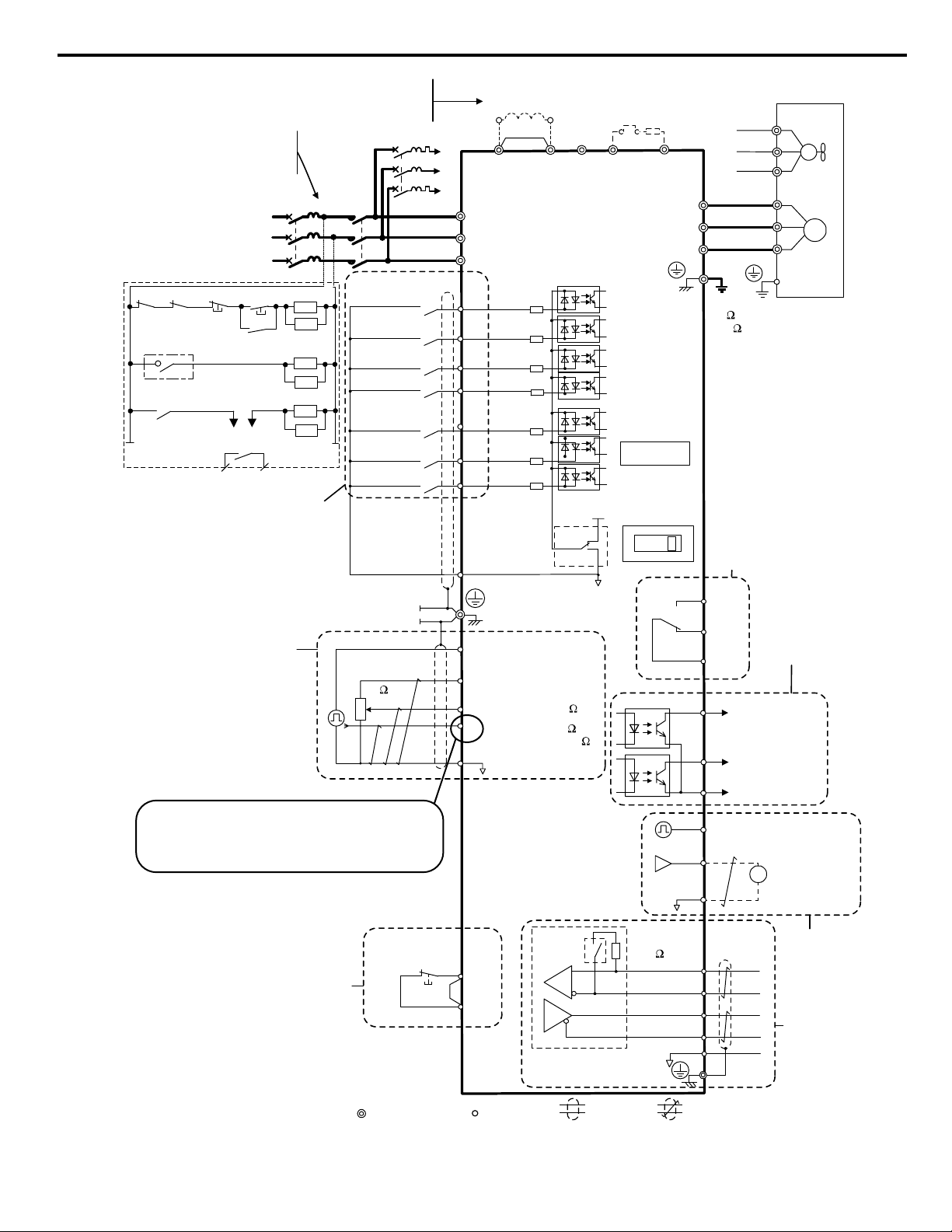
Connect the drive and peripheral devices as shown in Figure i.9. It is possible to run the drive via the digital operator without
connecting digital I/O wiring. Refer to Start-Up Programming and Operation on page 58 for instructions on operating the
drive
NOTICE: Inadequate branch short circuit protection could result in damage to the drive. Install adequate branch circuit short circuit protection
per applicable codes. The drive is suitable for circuits capable of delivering not more than 31,000 RMS symmetrical amperes, 240 Vac
maximum (200 V Class) and 480 Vac maximum (400 V Class).
NOTICE: When the wiring distance is greater than 100 meters, pay special attention to the motor insulation voltage or use a drive duty
motor. Failure to comply could lead to motor insulation breakdown.
NOTICE: Correctly set Sink/Source jumper S3 for internal power supply. Failure to comply may result in damage to the drive.
NOTICE: Do not connect AC control circuit ground to drive enclosure. Improper drive grounding can cause control circuit malfunction.
NOTICE: Route motor leads U/T1, V/T2, and W/T3 separate from all other leads to reduce possible interference related issues. Failure to
comply may result in abnormal operation of drive and nearby equipment.
NOTICE: The minimum load for the multi-function relay output MA-MB-MC is 10 mA. If a circuit requires less than 10 mA (reference value),
connect it to a photocoupler output (P1, P2, PC). Improper application of peripheral devices could result in damage to the photocoupler
output of the drive.
42
YASKAWA TOEP YAIQPM 02B YASKAWA AC Drive - iQpump Micro Quick Start Guide
Page 43
+
-
1 MCCB
MC
2 MCCB
r1
s1
t1
<3>
R/L1
S/L2
T/L3
For single-phase
200 V power supply
use R/L1 and S/L2.
Three phase
power supply
for 200 V / 400 V
Terminals +1, +2, − , B1, and B2
are for connecting options.
Never connect power supply
lines to these terminals.
Digital inputs
(default setting)
Forward run/stop
Not Used
External
pump fault
Fault reset
HAND Mode
S1
S2
S3
S4
S5
S6
S7
Multisetpoint 1
<4>
DC link choke
(option)
iQpumpMicro
Thermal relay
(option)
Main circuit
Control circuit
R/L1
S/L2
T/L3
<1>
<2>
-
B1+1+2 B2
Jumper
Motor
Cooling fan
Braking resistor
(option)
U/T1
V/T2
W/T3
M
M
r1
s1
t1
FU
FV
FW
U
V
W
Ground
10 or less (400 V class)
100 or less (200 V class)
Digital output
250 Vac, 10 mA to 1 A
30 Vdc, 10 mA to 1 A
(default setting)
Option card
connector
Fault
MA
P1
MB
MC
P2
MP
PC
During Run
(photocoupler 1)
Fault
(photocoupler 2)
Photocoupler
output common
Digital output
5 to 48 Vdc
2 to 50 mA
(default setting)
Pulse train output
0 to +10 Vdc
(2 mA)
Comm.
connector
AM
AC
AM
0 to 32 kHz
Analog monitor
output
Termination
resistor
Monitor
output
<6>
IG
R
+
R
-
S
+
S
-
MEMOBUS/
Modbus comm.
RS-485/422
120 , 1/2 W
Cable shield ground
DIP
switch
S2
main circuit terminal
shielded line
twisted-pair shielded line
control terminal
Safe Disable
Input
Safety switch
HC
H1
Jumper
<7>
System feedback,
HAND speed,
Main speed reference
Multi-function
programmable
RP
+V
A1
A2
AC
2 k
Pulse train input
(max. 32 kHz)
0 to +10 V (20 k )
Setting power supply
+10.5 max. 20 mA
0 to +10 V (20 k )
(0)4 to 20 mA (250 )
DIP
switch S3
Shield ground
terminal
0 V
SC
Sink
Source
<5>
24 V
+
24 V 8 mA
Wiring sequence should shut off
power to the drive when a fault
<8>
output is triggered.
TRX
ON
OFF
THRX
SA
1
2
TRX
MC
MC
MB
TRX
Fault relay contact
Braking resistor unit
Thermal relay trip contact
MC
SA
SA
THRX
V I
DIP switch S1
HAND Mode 2
Refer to “Transducer 2-Wire Connection Diagram”
and “Transducer 3-Wire Connection Diagram” figures
on the following pages for details on 24 V Power Supply
connections.
i.4 Electrical Installation
Figure i.9 Drive Standard Connection Diagram
YASKAWA TOEP YAIQPM 02B YASKAWA AC Drive - iQpump Micro Quick Start Guide
43
Page 44

i.4 Electrical Installation
<1> Remove the jumper when installing an optional DC link choke.
<2> The MC on the input side of the main circuit should open when the thermal relay is triggered.
<3> Self-cooled motors do not require separate cooling fan motor wiring.
<4> Connected using sequence input signal (S1 to S7) from NPN transistor; Default: sink mode (0 V com).
<5> Use only a +24 V internal power supply in sinking mode; the source mode requires an external power supply.
<6> Monitor outputs work with devices such as analog frequency meters, ammeters, voltmeters and wattmeters; they are not
intended for use as a feedback-type of signal.
<7> Disconnect the wire jumper between HC and H1 when utilizing the safety input. Refer to Wiring the Control Circuit
Terminal on page 52 for details on removing the jumper. The wire length for the Safe Disable input should not exceed
30 m.
<8> Note that if the drive is set to trigger a fault output whenever the fault restart function is activated (L5-02 = 1), then a
sequence to interrupt power when a fault occurs will result in shutting off the power to the drive as the drive attempts to restart
itself. The default setting for L5-02 is 0 (fault output active during restart attempt).
WARNING! Sudden Movement Hazard. Do not close the wiring for the control circuit unless the multifunction input terminal parameter is
properly set (S5 for 3-Wire; H1-05 = “0”). Improper sequencing of run/stop circuitry could result in death or serious injury from moving
equipment.
WARNING! Sudden Movement Hazard. Ensure start/stop and safety circuits are wired properly and in the correct state before energizing
the drive. Failure to comply could result in death or serious injury from moving equipment. When programmed for 3-Wire control, a momentary
closure on terminal S1 may cause the drive to start.
WARNING! When 3-Wire sequence is used, set the drive to 3-Wire sequence before wiring the control terminals and ensure parameter
b1-17 is set to 0 (drive does not accept a run command at power up (default). If the drive is wired for 3-Wire sequence but set up for 2-Wire
sequence (default) and if parameter b1-17 is set to 1 (drive accepts a Run command at power up), the motor will rotate in reverse direction
at power up of the drive and may cause injury.
WARNING! When the application preset function is executed (or A1-06 is set to any value other than 0) the drive I/O terminal functions
change. This may cause unexpected operation and potential damage to equipment or injury.
Figure i.10 illustrates an example of a 3-Wire sequence.
Stop relay (N.C.)
Run relay (N.O.)
S1
Run command (run on momentary close)
S2
Stop command (stop on momentary open)
S5
Foward/reverse command
(multi-function input: H1-05 = 0)
SC
Sequence input common
Drive
Figure i.10 3-Wire Sequence
44
YASKAWA TOEP YAIQPM 02B YASKAWA AC Drive - iQpump Micro Quick Start Guide
Page 45

u
Signal Wire (white)
24 V PSU to Drive
A2
24V
AC
FE
24V Power Supply
Shield
SIG
FE
Functional Earth Cable
(Blue)
J2
24V Power Supply
Transducer
Signal 4-20 mA
(typical)
CN1
Terminal
Block
TB1-2
TB1-1
TB2
TB1-3
EG
A2
A1
PC
P2
V+
AM
AC
MP
AC
P1
iQpump Micro Drive
(Earth
Ground)
Internal Circuit
Internal Circuit
iQpump Micro Drive
I/O Terminals
2
4
3
1
N/C
N/C
V+
Output
Example:
Customer supplied
pressure transducer
feedback device
(2-Wire)
Signal Wire (white)
24 V PSU to Drive
A2
24V
AC
FE
24V Power Supply
Shield
FE
Functional Earth Cable
(Blue)
J2
24V Power Supply
Transducer
Signal 0-10 Vdc
(typical)
CN1
Terminal
Block
Example:
Customer supplied
pressure transducer
feedback device
(3-Wire)
TB1-2
TB1-1
TB2
TB1-3
EG
A2
A1
PC
P2
V+
AM
AC
MP
AC
P1
iQpump Micro Drive
(Earth
Ground)
Internal Circuit
Internal Circuit
iQpump Micro Drive
I/O Terminals
Supply Common
2
4
3
1
N/C
V+
Output
Com
+
Transducer Connection Diagrams
i.4 Electrical Installation
YASKAWA TOEP YAIQPM 02B YASKAWA AC Drive - iQpump Micro Quick Start Guide
Figure i.11 Transducer 2-Wire Connection Diagram
Figure i.12 Transducer 3-Wire Connection Diagram
45
Page 46

i.5 Main Circuit Wiring
i.5 Main Circuit Wiring
This section describes the functions, specifications, and procedures required to safely and properly wire the main circuit of
the drive.
NOTICE: Do not solder the ends of wire connections to the drive. Soldered wiring connections can loosen over time. Improper wiring practices
could result in drive malfunction due to loose terminal connections.
u
Main Circuit Terminal Functions
Table i.2 Main Circuit Terminal Functions
Terminal Type Function Reference
R/L1
T/L3
U/T1
W/T3
B1
B2
⊕1
⊕2
⊕1
⊖
Main circuit power supply
input
Drive output Connects to the motor. 49V/T2
Braking resistor Available for connecting a braking resistor or the braking resistor unit option. –
DC link choke connection
DC power supply input For connecting a DC power supply. –
Connects line power to the drive.
Drives with single-phase 200 V input power use terminals R/L1 and S/L2 only.
Do NOT use T/L3.
These terminals are shorted at shipment. Remove the shorting bar between ⊕1
and ⊕2 when connecting a DC link choke to this terminal.
–S/L2
–
(2 terminals)
u
Wire Gauges and Tightening Torques
Ground Grounding Terminal 49
Select the appropriate wires and crimp terminals from Table i.3 through Table i.5.
Note: 1. Wire gauge recommendations based on drive continuous current ratings using 75 °C 600 Vac vinyl-sheathed wire assuming ambient
temperature within 30 °C and wiring distance shorter than 100 m.
2. Terminals ⊕1, ⊕2, ⊖, B1 and B2 are for connecting optional devices such as a braking resistor. Do not connect other non-specified
devices to these terminals.
• Consider the amount of voltage drop when selecting wire gauges. Increase the wire gauge when the voltage drop is greater
than 2% of motor rated voltage. Ensure the wire gauge is suitable for the terminal block. Use the following formula to
calculate the amount of voltage drop:
•
Line drop voltage (V) = 3 x wire resistance (Ω/km) x wire length (m) x current (A) x 10
-3
• Refer to instruction manual TOBP C720600 00 for braking unit or braking resistor unit wire gauges.
• Refer to UL Standards Compliance on page 102 for information on UL compliance.
Single-Phase 200 V Class
n
Table i.3 Wire Gauge and Torque Specifications
Drive
Model
BV0006
BV0010
Recomm.
Terminal
R/L1, S/L2, T/L3 12 14 to 10
U/T1, V/T2, W/T3 14 14 to 10
⊖, ⊕1, ⊕2
B1, B2 – 14 to 10
R/L1, S/L2, T/L3 10 14 to 10
U/T1, V/T2, W/T3 14 14 to 10
⊖, ⊕1, ⊕2
B1, B2 – 14 to 10
Gauge
AWG, kcmil
– 14 to 10
10 14 to 10
– 14 to 10
10 14 to 10
Wire Range
AWG, kcmil
Screw
Size
M4
M4
Tightening
Torque
N•m (lb.in.)
1.2 to 1.5
(10.6 to 13.3)
1.2 to 1.5
(10.6 to 13.3)
46
YASKAWA TOEP YAIQPM 02B YASKAWA AC Drive - iQpump Micro Quick Start Guide
Page 47

i.5 Main Circuit Wiring
Drive
Model
R/L1, S/L2, T/L3 10 14 to 10
U/T1, V/T2, W/T3 14 14 to 10
BV0012
⊖, ⊕1, ⊕2
B1, B2 – 14 to 10
R/L1, S/L2, T/L3 8 12 to 8
U/T1, V/T2, W/T3 10 12 to 8
BV0018
⊖, ⊕1, ⊕2
B1, B2 – 12 to 8
Three-Phase 200 V Class
n
Drive
Model
R/L1, S/L2, T/L3 14 18 to 14
U/T1, V/T2, W/T3 14 18 to 14
2V0006
⊖, ⊕1, ⊕2
B1, B2 – 18 to 14
R/L1, S/L2, T/L3 12 14 to 10
U/T1, V/T2, W/T3 14 14 to 10
2V0010
⊖, ⊕1, ⊕2
B1, B2 – 14 to 10
R/L1, S/L2, T/L3 12 14 to 10
U/T1, V/T2, W/T3 14 14 to 10
2V0012
⊖, ⊕1, ⊕2
B1, B2 – 14 to 10
R/L1, S/L2, T/L3 10 14 to 10
U/T1, V/T2, W/T3 10 14 to 10
2V0020
⊖, ⊕1, ⊕2
B1, B2 – 14 to 10
R/L1, S/L2, T/L3 8 10 to 6
U/T1, V/T2, W/T3 8 10 to 6
2V0030
⊖, ⊕1, ⊕2
B1, B2 – 14 to 10
R/L1, S/L2, T/L3 6 10 to 6
U/T1, V/T2, W/T3 8 10 to 6
2V0040
⊖, ⊕1, ⊕2
B1, B2 – 14 to 10
Terminal
Terminal
Recomm.
Gauge
AWG, kcmil
Wire Range
AWG, kcmil
– 14 to 10
10 14 to 10
– 12 to 8
8 12 to 8
Table i.4 Wire Gauge and Torque Specifications
Recomm.
Gauge
AWG, kcmil
Wire Range
AWG, kcmil
– 18 to 14
14 18 to 14
– 14 to 10
10 14 to 10
– 14 to 10
10 14 to 10
– 14 to 10
10 14 to 10
– 10 to 6
8 10 to 6 M5
– 10 to 6
6 10 to 6 M5
Screw
Size
M4
M5
Screw
Size
M3.5
M4
M4
M4
M4
M4
Tightening
Torque
N•m (lb.in.)
2.3 to 2.5
(20.4 to 22.1)
2.3 to 2.5
(20.4 to 22.1)
2 to 2.5
(17.7 to 22.1)
Tightening
Torque
N•m (lb.in.)
0.8 to 1.0
(7.1 to 8.9)
1.2 to 1.5
(10.6 to 13.3)
1.2 to 1.5
(10.6 to 13.3)
1.2 to 1.5
(10.6 to 13.3)
2.1 to 2.3
(18.6 to 20.4)
2 to 2.5
(17.7 to 22.1)
2.1 to 2.3
(18.6 to 20.4)
2 to 2.5
(17.7 to 22.1)
YASKAWA TOEP YAIQPM 02B YASKAWA AC Drive - iQpump Micro Quick Start Guide
47
Page 48

i.5 Main Circuit Wiring
Drive
Model
R/L1, S/L2, T/L3 4 6 to 4
U/T1, V/T2, W/T3 4 6 to 4
⊖, ⊕1, ⊕2
2V0056
B1, B2 – 10 to 6 M5
R/L1, S/L2, T/L3 3 8 to 2
U/T1, V/T2, W/T3 3 8 to 2
⊖, ⊕1, ⊕2
2V0069
B1, B2 – 8 to 6 M5
Three-Phase 400 V Class
n
Drive
Model
R/L1, S/L2, T/L3 14 14 to 10
U/T1, V/T2, W/T3 14 14 to 10
4V0002
4V0004
⊖, ⊕1, ⊕2
B1, B2 – 14 to 10
R/L1, S/L2, T/L3 14 14 to 10
4V0005
4V0007
4V0009
U/T1, V/T2, W/T3 14 14 to 10
⊖, ⊕1, ⊕2
B1, B2 – 14 to 10
R/L1, S/L2, T/L3 12 14 to 10
U/T1, V/T2, W/T3 14 14 to 10
4V0011
⊖, ⊕1, ⊕2
B1, B2 – 14 to 10
R/L1, S/L2, T/L3 10 14 to 6
U/T1, V/T2, W/T3 10 14 to 6
4V0018
⊖, ⊕1, ⊕2
B1, B2 – 14 to 10
R/L1, S/L2, T/L3 10 10 to 6
U/T1, V/T2, W/T3 10 10 to 6
4V0023
⊖, ⊕1, ⊕2
B1, B2 – 14 to 10
Terminal
Terminal
Recomm.
Gauge
AWG, kcmil
Wire Range
AWG, kcmil
– 6 to 4
6 8 to 4 M6
– 8 to 2
6 6 to 4 M6
Table i.5 Wire Gauge and Torque Specifications
Recomm.
Gauge
AWG, kcmil
Wire Range
AWG, kcmil
– 14 to 10
14 14 to 10
– 14 to 10
10 14 to 10
– 14 to 10
10 14 to 10
– 14 to 6
8 14 to 6 M5
– 10 to 6
8 10 to 6 M5
Screw
Size
M6
M8
Screw
Size
M4
M4
M4
M4
M4
Tightening
Torque
N•m (lb.in.)
5.4 to 6.0
(47.8 to 53.1)
2.7 to 3.0
(23.9 to 26.6)
5.4 to 6.0
(47.8 to 53.1)
9.9 to 11
(87.6 to 97.4)
2.7 to 3.0
(23.9 to 26.6)
5.4 to 6.0
(47.8 to 53.1)
Tightening
Torque
N•m (lb.in.)
1.2 to 1.5
(10.6 to 13.3)
1.2 to 1.5
(10.6 to 13.3)
1.2 to 1.5
(10.6 to 13.3)
2.1 to 2.3
(18.6 to 20.4)
2 to 2.5
(17.7 to 22.1)
2.1 to 2.3
(18.6 to 20.4)
2 to 2.5
(17.7 to 22.1)
48
YASKAWA TOEP YAIQPM 02B YASKAWA AC Drive - iQpump Micro Quick Start Guide
Page 49

i.5 Main Circuit Wiring
Drive
Model
R/L1, S/L2, T/L3 8 10 to 6
U/T1, V/T2, W/T3 8 10 to 6
4V0031
4V0038
u
Main Circuit Terminal Power Supply and Motor Wiring
⊖, ⊕1, ⊕2
B1, B2 – 14 to 10
R/L1, S/L2, T/L3 6 10 to 6
U/T1, V/T2, W/T3 8 10 to 6
⊖, ⊕1, ⊕2
B1, B2 – 10 to 8
Terminal
Recomm.
Gauge
AWG, kcmil
– 10 to 6
6 10 to 6 M6
– 10 to 6
6 10 to 6 M6
Wire Range
AWG, kcmil
Screw
Size
M5
M5
Tightening
Torque
N•m (lb.in.)
3.6 to 4.0
(31.8 to 35.4)
2.7 to 3.0
(23.9 to 26.6)
5.4 to 6.0
(47.8 to 53.1)
3.6 to 4.0
(31.8 to 35.4)
2.7 to 3.0
(23.9 to 26.6)
5.4 to 6.0
(47.8 to 53.1)
This section outlines the various steps, precautions, and checkpoints for wiring the main circuit terminals and motor terminals.
NOTICE: When connecting the motor to the drive output terminals U/T1, V/T2, and W/T3, the phase order for the drive and motor should
match. Failure to comply with proper wiring practices may cause the motor to run in reverse if the phase order is backward.
NOTICE: Route motor leads U/T1, V/T2, and W/T3 separate from all other leads to reduce possible interference related issues. Failure to
comply may result in abnormal operation of drive and nearby equipment.
NOTICE: Do not connect phase-advancing capacitors or LC/RC noise filters to the output circuits. Improper application of noise filters could
result in damage to the drive.
NOTICE: Do not connect the AC power line to the output motor terminals of the drive. Failure to comply could result in death or serious
injury by fire as a result of drive damage from line voltage application to output terminals.
Cable Length Between Drive and Motor
n
When the cable length between the drive and the motor is too long (especially at low frequency output), note that the cable
voltage drop may cause reduced motor torque. Drive output current will increase as the leakage current from the cable increases.
An increase in leakage current may trigger an overcurrent situation and weaken the accuracy of the current detection.
Adjust the drive carrier frequency according to the following table. If the motor wiring distance exceeds 100 m because of the
system configuration, reduce the ground currents.
Refer to Table i.6 to set the carrier frequency to an appropriate level.
Table i.6 Cable Length Between Drive and Motor
Cable Length 50 m or shorter 100 m or shorter Longer than 100 m
Carrier Frequency 15 kHz or less 5 kHz or less 2 kHz or less
Note: When setting carrier frequency, calculate the cable length as the total distance of wiring to all connected motors when running multiple
Ground Wiring
n
motors from a single drive.
Follow the precautions to wire the ground for one drive or a series of drives.
WARNING! Electrical Shock Hazard. Always use a ground wire that complies with technical standards on electrical equipment and minimize
the length of the ground wire. Improper equipment grounding may cause dangerous electrical potentials on equipment chassis, which could
result in death or serious injury.
WARNING! Electrical Shock Hazard. Be sure to ground the drive ground terminal. (200 V Class: Ground to 100 Ω or less, 400 V Class:
Ground to 10 Ω or less). Improper equipment grounding could result in death or serious injury by contacting ungrounded electrical equipment.
NOTICE: Do not share the ground wire with other devices such as welding machines or large-current electrical equipment. Improper
equipment grounding could result in drive or equipment malfunction due to electrical interference.
NOTICE: When using more than one drive, ground multiple drives according to instructions. Improper equipment grounding could result in
abnormal operation of drive or equipment.
Refer to Figure i.13 when using multiple drives. Do not loop the ground wire.
YASKAWA TOEP YAIQPM 02B YASKAWA AC Drive - iQpump Micro Quick Start Guide
49
Page 50

i.5 Main Circuit Wiring
Figure i.13 Multiple Drive Wiring
u
Control Circuit Terminal Block Functions
Drive parameters determine which functions apply to the multi-function digital inputs (S1 to S7), multi-function digital outputs
(MA, MB), multi-function pulse inputs and outputs (RP, MP) and multi-function photocoupler outputs (P1, P2). The default
is called out next to each terminal in Figure i.9.
WARNING! Sudden Movement Hazard. Always check the operation and wiring of control circuits after being wired. Operating a drive with
untested control circuits could result in death or serious injury.
WARNING! Confirm the drive I/O signals and external sequence before starting test run. Setting parameter A1-06 may change the I/O
terminal function automatically from the factory setting. Failure to comply may result in death or serious injury.
Input Terminals
n
Table i.7 Control Circuit Input Terminals
Type No. Terminal Name (Function) Function (Signal Level) Default Setting
Multi-function input 1 (Closed: Forward run, Open:
S1
Stop)
Multi-Function
Digital Inputs
Safe Disable
Input
Main
Frequency
Reference
Input
S2 Multi-function input 2 (Not used/Through mode)
S3 Multi-function input 3 (External pump fault (N.O.)
S4 Multi-function input 4 (Fault reset)
S5 Multi-function input 5 (Multi-step speed reference 1)
S6 Multi-function input 6 (HAND Mode)
S7 Multi-function input 7 (HAND Mode 2)
SC Multi-function input common (Control common) Sequence common
HC Power supply for safe disable input +24 Vdc (max 10 mA allowed)
H1 Safe disable input
RP Multi-function pulse train input (frequency reference)
+V Analog input power supply +10.5 Vdc (max allowable current 20 mA)
A1 Multi-function analog input 1 (frequency reference) Input voltage 0 to +10 Vdc (20 kΩ) resolution 1/1000
A2 Multi-function analog input 2 (frequency reference)
AC Frequency reference common 0 Vdc
Photocoupler
24 Vdc, 8 mA
Note: Drive preset to sinking mode. When using source mode, set
DIP switch S3 to allow for a 24 Vdc (±10%) external power supply.
Refer to Sinking/Sourcing Mode Switch on page 54.
Open: Output disabled
Closed: Normal operation
Note: Disconnect wire jumper between HC and H1 when using the
safe disable input. The wire length should not exceed 30 m.
Response frequency: 0.5 to 32 kHz
(Duty Cycle: 30 to 70%)
(High level voltage: 3.5 to 13.2 Vdc)
(Low level voltage: 0.0 to 0.8 Vdc)
(input impedance: 3 kΩ)
Input voltage or input current (Selected by DIP switch S1 and H3-09)
0 to +10 Vdc (20 kΩ),
Resolution: 1/1000
4 to 20 mA (250 Ω) or 0 to 20 mA (250 Ω),
Resolution: 1/500
Output Terminals
n
Type No. Terminal Name (Function) Function (Signal Level) Default Setting
Multi-Function Digital
<1>
Output
50
Table i.8 Control Circuit Output Terminals
MA N.O. (fault)
MB N.C. output (fault)
MC Digital output common
Digital output
30 Vdc, 10 mA to 1 A; 250 Vac, 10 mA to 1 A
Minimum load: 5 Vdc, 10 mA (reference value)
YASKAWA TOEP YAIQPM 02B YASKAWA AC Drive - iQpump Micro Quick Start Guide
Page 51

S1 S2 S3 S4 S5 S6 S7 HC SC H1 RP
R+ R– S+ S– IG
P1 P2 PC A1 A2 +V AC AM AC MP
MCMBMA
S1 S2 S3 S4 S5 S6 S7 HC SC H1 RP
R+ R- S+ S- IG
P1 P2 PC A1 A2 +V AC AM AC MP
MCMBMA
i.5 Main Circuit Wiring
Type No. Terminal Name (Function) Function (Signal Level) Default Setting
Multi-Function
Photocoupler Output
Monitor Output
<1> Do not assign functions to digital relay outputs that involve frequent switching. This may shorten relay performance life. Switching life is estimated
at 200,000 times (assumes 1 A, resistive load).
<2> Connect a suppression diode as shown in Figure i.14 when driving a reactive load such as a relay coil. Ensure the diode rating is greater than the
circuit voltage.
<3> When set for sourcing. +5 V/1.5 kΩ or higher, +8 V/3.5 kΩ or higher, +10 V/10 kΩ or higher.
<4> When set for sinking, the external power supply should be +12 Vdc, ±5% with 16 mA or less.
P1 Photocoupler output 1 (During run)
P2 Photocoupler output 2 (Frequency agree)
Photocoupler output 48 Vdc, 2 to 50 mA
<2>
PC Photocoupler output common
MP Pulse train output (Output frequency)
32 kHz (max)
<3> <4>
AM Analog monitor output 0 to 10 Vdc (2 mA or less) Resolution: 1/1000
AC Monitor common 0 V
B
A – External power, 48 V max.
B – Suppression diode
Serial Communication Terminals
n
Table i.9 Control Circuit Terminals: Serial Communications
Type No. Signal Name Function (Signal Level)
R+ Communications input (+)
R- Communications input (-)
MEMOBUS/Modbus
Communication
S+ Communications output (+)
S- Communications output (-)
IG Shield ground 0 V
u
Terminal Configuration
A
C
D
C – Coil
D – 50 mA or less
Figure i.14 Connecting a Suppression Diode
MEMOBUS/Modbus communication: Use a
RS-485 or RS-422 cable to connect the drive.
RS-485/422
MEMOBUS/
Modbus
communication
protocol 115.2 kbps
(max.)
Figure i.15 Removable Control Circuit Terminal Block
YASKAWA TOEP YAIQPM 02B YASKAWA AC Drive - iQpump Micro Quick Start Guide
51
Page 52
i.5 Main Circuit Wiring
Wire Size and Torque Specifications
n
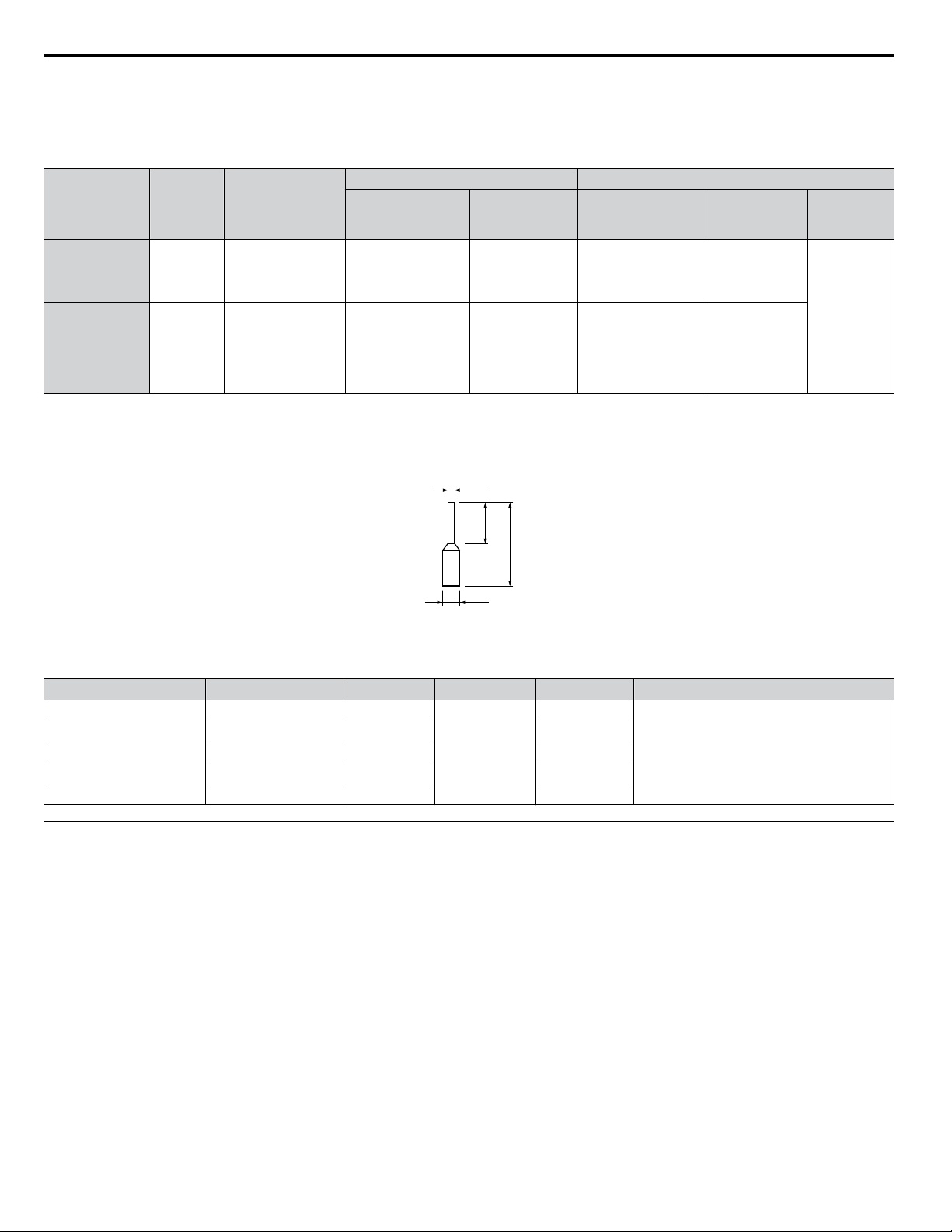
Select appropriate wire type and size from Table i.10. For simpler and more reliable wiring, crimp ferrules to the wire ends.
Refer to Table i.11 for ferrule terminal types and sizes.
Table i.10 Wire Size and Torque Specifications (Same for All Models)
Terminal
MA, MB, MC M3
S1-S7, SC, RP,
+V, A1, A2, AC,
HC, H1, P1, P2,
PC, MP, AM,
AC, S+, S-, R+,
R-, IG
Ferrule-Type Wire Terminations
n
Screw
Size
M2
Tightening
Torque
N•m
(in-lbs)
0.5 to 0.6
(4.4 to 5.3)
0.22 to 0.25
(1.9 to 2.2)
Stranded: 0.25 to 1.5
(24 to 16)
Single: 0.25 to 1.5
(24 to 16)
Stranded: 0.25 to 1.0
(24 to 18)
Single: 0.25 to 1.5
(24 to 16)
Bare Wire Terminal Ferrule-Type Terminal
Applic. wire size
Applic. wire size
mm2 (AWG)
Recomm. mm
(AWG)
0.75 (18)
0.75 (18)
2
2
mm
(AWG)
0.25 to 1.0
(24 to 17)
0.25 to 0.5
(24 to 20)
Recomm. mm
(AWG)
0.5 (20)
0.5 (20)
2
Wire Type
Shielded line,
etc.
Crimp a ferrule to signal wiring to improve wiring simplicity and reliability. Use CRIMPFOX 6, a crimping tool manufactured
by PHOENIX CONTACT.
d1
6 mm
L
d2
Figure i.16 Ferrule Dimensions
Table i.11 Ferrule Terminal Types and Sizes
Size mm
u
Wiring the Control Circuit Terminal
2
(AWG)
0.25 (24) AI 0.25-6YE 10.5 0.8 2.0
0.34 (22) AI 0.34-6TQ 10.5 0.8 2.0
0.5 (20) AI 0.5-6WH 12 1.1 2.5
0.75 (18) AI 0.75-6GY 12 1.3 2.8
1.0 AI 1-6RD 12 1.5 3.0
Type L (mm) d1 (mm) d2 (mm) Manufacturer
PHOENIX CONTACT
This section describes the proper procedures and preparations for wiring the control terminals.
WARNING! Electrical Shock Hazard. Do not remove covers or touch the circuit boards while the power is on. Failure to comply could result
in death or serious injury.
NOTICE: Separate control circuit wiring from main circuit wiring (terminals R/L1, S/L2, T/L3, B1, B2, U/T1, V/T2, W/T3,
other high-power lines. Improper wiring practices could result in drive malfunction due to electrical interference.
NOTICE: Separate wiring for digital output terminals MA, MB and MC from wiring to other control circuit lines. Improper wiring practices
could result in drive or equipment malfunction or nuisance trips.
NOTICE: Use a class 2 power supply (UL standard) when connecting to the control terminals. Improper application of peripheral devices
could result in drive performance degradation due to improper power supply.
NOTICE: Insulate shields with tape or shrink tubing to prevent contact with other signal lines and equipment. Improper wiring practices could
result in drive or equipment malfunction due to short circuit.
NOTICE: Connect the shield of shielded cable to the appropriate ground terminal. Improper equipment grounding could result in drive or
equipment malfunction or nuisance trips.
⊖, ⊕
1, ⊕2) and
Wire the control terminals using Figure i.17 as a guide. Prepare the ends of the control circuit wiring as shown in Figure i.
18. Refer to Wire Size and Torque Specifications on page 52.
52
YASKAWA TOEP YAIQPM 02B YASKAWA AC Drive - iQpump Micro Quick Start Guide
Page 53

Preparing wire
terminal ends
E
A
B
D
RP
+V
A1
A2
AC
A
B
C
D
E
F
G
2 k
i.5 Main Circuit Wiring
NOTICE: Do not tighten screws beyond the specified tightening torque. Failure to comply may damage the terminal block.
NOTICE: Use shielded twisted-pair cables as indicated to prevent operating faults. Improper wiring practices could result in drive or
equipment malfunction due to electrical interference.
Connect control wires as shown in the following figure:
A – Control terminal block
B – Avoid fraying wire strands when
stripping insulation from wire. Strip
D – Loosen screw to insert wire.
E – Blade depth of 0.4 mm or less
Blade width of 2.5 mm or less
length 5.5 mm.
C – Single wire or stranded wire
Figure i.17 Terminal Board Wiring Guide
F
A
B
A – Drive side
B – Connect shield to ground terminal
of drive.
C
E
D
D – Control device side
E – Shield sheath (Insulate with tape)
F – Shield
C – Insulation
Figure i.18 Preparing the Ends of Shielded Cables
When setting the frequency by analog reference from an external potentiometer, use shielded twisted-pair wires and ground
the shield of twisted-pair wires to the ground terminal of the drive.
NOTICE: The analog signal lines between the drive and the operator station or peripheral equipment should not exceed 50 meters when
using an analog signal from a remote source to supply the frequency reference. Failure to comply could result in poor system performance.
A – Drive
B – Ground terminal (shield
YASKAWA TOEP YAIQPM 02B YASKAWA AC Drive - iQpump Micro Quick Start Guide
Figure i.19 Wiring the Frequency Reference to the Control Circuit Terminals (External Reference)
connection)
C – (RP) Pulse train (maximum 32 kHz)
D – (+V) Frequency setting power
source +10.5 Vdc maximum 20 mA
E – (A1) Main speed frequency
reference 0 to +10 Vdc (20 kΩ)
F – (A2) Multi-function analog input
0 to +10 Vdc (20 kΩ) or
4 to 20 mA (250 Ω)/
0 to 20 mA (250 Ω)
G – Frequency setting potentiometer
53
Page 54

DIP Switch S3
SINK
SOURCE
Drive
Shielded cable
Forward run/stop
Reverse run/stop
External fault N.O.
Fault reset
Multi-speed step 1
Multi-speed step 2
Jog reference
Multi-function input
S1
S2
S3
S3
+24V
S4
S5
S6
S7
SC
SINK
SOURCE
SINK
SOURCE
i.5 Main Circuit Wiring
u
Sinking/Sourcing Mode Switch
Set the DIP switch S3 on the front of the drive to switch the digital input terminal logic between sinking mode and sourcing
mode; the drive is preset to sinking mode.
Table i.12 Sinking/Sourcing Mode Setting
Set Value Details
SINK Sinking Mode (0 V common): default setting
SOURCE Sourcing Mode (+24 V common)
Figure i.20 DIP Switch S3
Transistor Input Signal Using 0 V Common/Sink Mode
n
When controlling the digital inputs by NPN transistors (0 V common/sinking mode), set the DIP switch S3 to SINK and use
the internal 24 V power supply.
Figure i.21 Sinking Mode: Sequence from NPN Transistor (0 V Common)
54
YASKAWA TOEP YAIQPM 02B YASKAWA AC Drive - iQpump Micro Quick Start Guide
Page 55

Forward run / stop
Reverse run / stop
External fault N.O.
Fault rest
Multi-step speed 1
Multi-step speed 2
Jog frequency
External
power supply
Shielded cable
Drive
Multi-function input
S1
S2
S3
+24V
S4
S5
S6
S7
SC
S3
SINK
SOURCE
+24 V
SINK
SOURCE
i.5 Main Circuit Wiring
Transistor Input Signal Using +24 V Common/Source Mode
n
When controlling digital inputs by PNP transistors (+24 V common/sourcing mode), set the DIP switch S3 to SOURCE and
use an external 24 V power supply.
u
The main frequency reference can either be a voltage or current signal input. For voltage signals both analog inputs, A1 and
A2, can be used, for current signals A2 must be used.
When using input A2 as a voltage input, set DIP switch S1 to “V” (left position) and program parameter H3-09 to 0 (0 to +10
Vdc with lower limit) or 1 (0 to +10 Vdc without lower limit).
To use current input at terminal A2, set the DIP switch S1 to "I" (default setting) and set parameter H3-09 = 2 or 3 (4-20 mA
or 0-20 mA). Set parameter H3-10 = 0 (frequency reference).
Figure i.22 Source Mode: Sequence from PNP Transistor (+24 V Common)
DIP Switch S1 Analog Input Signal Selection
Note: If Terminals A1 and A2 are both set for frequency reference (H3-02 = 0 and H3-10 = 0), the addition of both input values builds the frequency
reference.
Table i.13 Frequency Reference Configurations
Voltage Input Current Input
Drive
0 to 10 V
+10.5 V
+V
20 mA current
Main speed
frequency reference
A1
(voltage input)
Main speed
A2
frequency reference
(current input)
AC
Frequency reference
common
4 to 20 mA input
or
0 to 20 mA input
+V
A1
A2
AC
Drive
+10.5 V
20 mA current
Main speed
frequency reference
(voltage input)
Main speed
frequency reference
(current input)
Frequency reference
common
YASKAWA TOEP YAIQPM 02B YASKAWA AC Drive - iQpump Micro Quick Start Guide
55
Page 56

V I
i.5 Main Circuit Wiring
Figure i.23 DIP Switch S1
Table i.14 DIP Switch S1 Settings
Setting Value Description
V (eft position) Voltage input (0 to 10 V)
I (right position) Current input (4 to 20 mA or 0 to 20 mA): default setting
Table i.15 Parameter H3-09 Details
No. Parameter Name Description
Selects the signal level for terminal A2.
H3-09
Frequency ref. (current)
terminal A2 signal level selection
0: 0 to +10 V, unipolar input (with lower limit)
1: 0 to +10 V, bipolar input (no lower limit)
2: 4 to 20 mA
3: 0 to 20 mA
Setting
Range
0 to 3 2
Default
Setting
u
Wiring Checklist
No.
1 Check drive model number to ensure receipt of correct model. 37
2 Check for correct braking resistors, DC link chokes, noise filters, and other peripheral devices. –
3 Ensure area surrounding the drive complies with specifications. 39
4 The voltage from the power supply should fall within the input voltage specification range of the drive. –
5 The voltage rating for the motor should match the drive output specifications. 37
6 Confirm proper branch circuit protection exists per National and Local codes. 42
7 Properly wire the power supply to drive terminals R/L1, S/L2 and T/L3. –
8
9 Use 600 Vac vinyl-sheathed wire for the power supply and motor lines. 46
10
11 Properly ground the drive. 49
12 Tightly fasten all terminal screws. Refer to Table i.3, Table i.4, or Table i.5. 46
Item Page
Drive, peripherals, option cards
Installation area and physical setup
Power supply voltage, output voltage
Main circuit wiring
Properly wire the drive and motor together.
The motor lines and drive output terminals R/T1, V/T2 and W/T3 should match in order to produce the desired
49
phase order. If the phase order is incorrect, the drive will rotate in the opposite direction.
Use the correct wire gauges for the main circuit. Refer to Table i.3, Table i.4, or Table i.5. 46
When using comparatively long motor cable, calculate the amount of voltage drop.
Motor rated voltage (V) x 0.02 ≥
3 x voltage resistance (Ω/km) x cable length (m) x motor rated current (A) x 10
If the cable between the drive and motor exceeds 50 m, adjust the carrier frequency (C6-02) accordingly. 49
-3
46
56
YASKAWA TOEP YAIQPM 02B YASKAWA AC Drive - iQpump Micro Quick Start Guide
Page 57

i.5 Main Circuit Wiring
No. Item Page
Set up overload protection circuits when running multiple motors from a single drive.
Power supply
13
Note: Close MC1 through MCn before operating the drive.
If using a braking resistor or dynamic braking resistor unit, install a magnetic contactor. Properly install the resistor,
14
and ensure that overload protection shuts off the power supply.
15 Verify phase advancing capacitors are NOT installed on the output side of the drive. –
16 Use twisted-pair cables for all drive control circuit wiring. –
17 Ground the shields of shielded wiring to the GND terminal. 52
18 If using a 3-Wire sequence, set parameters for MFDI terminals S1 through S7, and properly wire control circuits. 44
19 Check for any other wiring mistakes. Only use a multimeter to check wiring. –
20 Properly fasten the control circuit terminal screws in the drive. Refer to Table i.3, Table i.4, or Table i.5. 46
21 Pick up all wire clippings. –
22 Ensure that no frayed wires on the terminal block are touching other terminals or connections. –
23 Properly separate control circuit wiring and main circuit wiring. –
24 Analog signal line wiring should not exceed 50 m. –
25 Safe Disable Input wiring should not exceed 30 m. –
Drive
MC1 - MCn
OL 1 - OLn
Control circuit wiring
OL1
MC1
OL2
MC2
OLn
MCn
... magnetic contactor
... thermal relay
M1
M2
Mn
–
–
YASKAWA TOEP YAIQPM 02B YASKAWA AC Drive - iQpump Micro Quick Start Guide
57
Page 58

5
1
11
12
13
8
15
14
16
10
2
3
AUTO OFF
HAND
4 6
7
9
AUTO
OFF
HAND
AUTO
HAND
i.6 Start-Up Programming and Operation
i.6 Start-Up Programming and Operation
u
Keys, Displays, and LEDs on the Standard LED Operator
Table i.16 Keys and Displays on the LED Operator
No. Display Name Function
1 Data Display Area Displays the frequency reference, parameter number, etc.
2 ESC Key Returns to the previous menu.
3 RESET Key
Moves the cursor to the right.
Resets the drive to clear a fault situation.
Selects the source of Run command and frequency reference.
4
AUTO Key
• Set the drive to AUTO mode.
• Run command input source depends on b1-02.
• Frequency reference input source depends on b1-01.
5 Up Arrow Key
6 Down Arrow Key
7
OFF Key Follows the stopping method set in b1-03 to stop drive operation.
8 ENTER Key
Scrolls up to display the next item, selects parameter numbers, and increments setting
values.
Scrolls down to display the previous item, selects parameter numbers, and decrements
setting values.
• Enters parameter values and settings.
• Selects a menu item to move between displays.
The drive runs at a selectable frequency reference source as set by P5-01.
9
HAND Key
• Set the drive to HAND mode.
• When P5-03 is set to 1, HAND and AUTO mode can be switched while the drive is
running.
10
11
AUTO Light Lit while the drive is in AUTO mode.
HAND Light Lit while the drive is in HAND mode.
12 ALM LED Light Lit or flashing when the drive detects an alarm or error.
13 REV LED Light Lit when motor is rotating in reverse.
14 DRV LED Light Lit when in Drive Mode or Auto-Tuning.
15 FOUT LED Light Lit then displaying output frequency.
58
YASKAWA TOEP YAIQPM 02B YASKAWA AC Drive - iQpump Micro Quick Start Guide
Page 59

XXXX
XX
XX
XX
XX
XX
XX
XX
XX
XX
XX
XX
XX
XX
X
:
:
:
:
Turn the power on
Forward Selection
Reverse Selection
Output Frequency
Output Current
Output Voltage
Monitor Display
Verify Menu
Set Up Mode
Parameter Setting Mode
Auto-Tuning
Description of Key Operations
Note: “XX” characters are shown in this manual.
The drive will display the actual setting values.
PROGRAMMING MODE
DRIVE MODE
<1>
Application Preset
i.6 Start-Up Programming and Operation
No. Display Name Function
Port used for USB Copy Unit, LCD Operator Keypad, and for connecting to a PC.
NOTICE: Use only specified cable when making connections to the drive. Failure
16 – Communication Port
u
Menu Structure for Digital LED Operator
to comply may damage the drive.
NOTICE: Do not open the port cover wider than 90 degrees. Failure to comply
may break the port cover and leave the unprotected port susceptible to damage.
<1> Reverse can only be selected when LOCAL is set.
Powering Up the Drive
n
Figure i.24 Digital LED Operator Screen Structure
Review the following checklist before turning the power on.
Power supply voltage
Drive output terminals
and motor terminals
Control circuit terminals Check control circuit terminal connections.
Drive control terminal status Open all control circuit terminals (off).
Status of the load
and connected machinery
YASKAWA TOEP YAIQPM 02B YASKAWA AC Drive - iQpump Micro Quick Start Guide
Item to Check Description
Ensure the power supply voltage is correct:
200 V class: single-phase 200 to 240 Vac 50/60 Hz
200 V class: 3-phase 200 to 240 Vac 50/60 Hz
400 V class: 3-phase 380 to 480 Vac 50/60 Hz
Properly wire the power supply input terminals (R/L1, S/L2, T/L3).
(for single-phase 200 V class models, wire only R/L1 and S/L2)
Check for proper grounding of drive and motor.
Properly wire drive output terminals U/T1, V/T2, and W/T3 with motor terminals U, V, and W.
Uncouple the motor from the load.
59
Page 60

F2F1
ESC
M M
AUTO OFF
ENTERRESET
ALM
DIGITAL OPERATOR JVOP-183
HAND
12
11
9
8
1
2
3
10
4 5 6 7
AUTO
OFF
HAND
AUTO
HAND
i.6 Start-Up Programming and Operation
u
Keys and Displays on the Optional HOA Keypad
Figure i.25 Keys and Displays on the HOA Keypad
No. Display Name Function
1
2
F1
F2
ESC
3 RESET Key
4
5 Up Arrow Key Scrolls up to display the next item, selects parameter numbers, and increments setting values.
Function Key
(F1, F2)
ESC Key
AUTO Key
The functions assigned to F1 and F2 vary depending on the currently displayed menu. The name of
each function appears in the lower half of the display window.
• Returns to the previous display.
• Moves the cursor one space to the left.
• Pressing and holding this button will return to the Frequency Reference display.
• Moves the cursor to the right.
• Resets the drive to clear a fault situation.
Selects the source of Run command and frequency reference.
• Set the drive to AUTO mode.
• Run command input source depends on b1-02.
• Frequency reference input source depends on b1-01.
6 Down Arrow Key Scrolls down to display the previous item, selects parameter numbers, and decrements setting values.
7
8 ENTER Key
OFF Key Follows the stopping method set in b1-03 to stop drive operation.
• Enters parameter values and settings.
• Selects a menu item to move between displays.
The drive runs at a selectable frequency reference source as set by P5-01.
9
HAND Key
• Set the drive to HAND mode.
• When P5-03 is set to 1, HAND and AUTO mode can be switched while the drive is running.
10
11
AUTO Light Lit while the drive is in AUTO mode.
HAND Light Lit while the drive is in HAND mode.
12 ALM LED Light Lit or flashing when the drive detects an alarm or error.
60
YASKAWA TOEP YAIQPM 02B YASKAWA AC Drive - iQpump Micro Quick Start Guide
Page 61

i.6 Start-Up Programming and Operation
u
LCD Display
Figure i.26 LCD Display
Table i.17 Display and Contents
No. Name Display Content
MODE Displayed when in Mode Selection.
QMONI: Use F1/F2 Instructions to access the Quick Monitors.
MENU: Use UP/
DWN
1 Operation Mode Menus
MONITR Displayed when in Monitor Mode.
VERIFY Indicates the Verify Menu.
PRMSET Displayed when in Parameter Setting Mode.
A.TUNE Displayed during Auto-Tuning.
SETUP Displayed when in Setup Mode.
2 Mode Display Area
DRV Displayed when in Drive Mode.
PRG Displayed when in Programming Mode.
3 Ready Rdy Indicates the drive is ready to run.
4 Data Display — Displays specific data and operation data.
OPR Displayed when the frequency reference is assigned to the HOA keypad.
Frequency
5
Reference
Assignment
<1>
COM
OP Displayed when the frequency reference is assigned to option card connected to the drive.
AI Displayed when the function reference is assigned to an analog input.
OFF Displayed when HAND mode is OFF.
RSEQ
6
LOCAL/REMOTE
Display
<2>
LSEQ Displayed when the Run command is supplied from the HOA keypad.
RREF
LREF Displayed when the Run command is supplied from the HOA keypad.
<-MONITOR->
DATA
7
Function Key 2
(F2)
→
RESET
Monitor
Instructions to access the next menu item.
Displayed when the frequency reference is assigned to the MEMOBUS/Modbus
Communication Inputs of the drive.
Displayed when the Run command is supplied from a remote source.
Note: This display will blink when b1-02 is set to 1 (Digital Inputs).
Displayed when the Run command is supplied from a remote source.
Note: This display will blink when b1-01 is set to 1 (Analog Inputs).
Pressing
Pressing
Pressing
Pressing
Pressing
F2
displays the next Quick Monitor.
F2
scrolls to the next display.
F2
scrolls the cursor to the right.
F2
resets the existing drive fault error.
F2
switches Monitor mode.
YASKAWA TOEP YAIQPM 02B YASKAWA AC Drive - iQpump Micro Quick Start Guide
61
Page 62

20 10/01/01 00:00
Second per month
+ 0 sec
YYYY/MM/DD HH:MM
A
B
i.6 Start-Up Programming and Operation
No. Name Display Content
8 FWD/REV
9
<1> Displayed when in Frequency Reference Mode.
<2> Displayed when in Frequency Reference Mode and Monitor Mode.
u
Setting the Real Time Clock
Function Key 1
(F1)
FWD Indicates forward motor operation.
REV Indicates reverse motor operation.
<-MONITOR->
←
Home
ESC
Monitor
Pressing
Pressing
Pressing
Pressing
Pressing
F1
displays the next Quick Monitor.
F1
scrolls the cursor to the left.
F1
returns to the top menu (Frequency Reference).
F1
returns to the previous display.
F1
switches Monitor mode.
The time and date must be set when a new HOA keypad is plugged in and the drive is powered up. The HOA keypad will
display the time and date setup screen for 30 seconds. If a button is not pressed during this time, the display will clear and a
“Clock Not Set” alarm will flash. Pressing the F2 (Data) key will display the setting screen again.
Feedback Loss Wire Break Alarm
n
If there is no sensor wired to the drive, a “Feedback Loss – Wire Break” alarm will flash on the display. Providing the proper
feedback device signal will clear the Feedback Loss alarm.
The drive requires a feedback device (e.g., pressure transducer, flow meter, etc.) to perform automatic system regulation. Any
analog 0~10 V or 4-20 mA feedback device can be used in combination with the drive.
Note: The factory default setting for the drive is 4~20 mA feedback device connected to analog input A2.
Real Time Clock Setting Display
n
Note: Setting the Real-Time Clock will clear a “Clock Not Set” alarm.
A – Real Time Clock Setting Display
Set in 24-Hour Clock Time
Figure i.27 Real Time Clock Adjustment Display
Display Description
YYYY Set the year with the last two digits.
MM Set the month with two digits.
DD Set the day with two digits.
HH:MM
Second per month
Moving the Cursor
Pressing the F2 key or the RESET key will move the cursor to the digit on the right. Pressing the F1 key will move the cursor
Set the hours and minutes, with two digits for each.
Note: Set in 24-hour clock time. After initial setup, the time will display in 12-hour clock time.
Set the gain or loss in seconds per month.
Note: This does not need to be set for the RTC to function properly.
B – Gain/Loss Adjustment Display
to the left.
62
YASKAWA TOEP YAIQPM 02B YASKAWA AC Drive - iQpump Micro Quick Start Guide
Page 63

ALM
20 10/01/01 00:00
Second per month
+ 0 sec
YYYY/MM/DD HH:MM
ALM
ALM
Entry accepted
- MODE -
U5-99= 0.0PSI
U1-02= 0.00Hz
U1-91= 0.0PSI
DRV
Auto Setpoint
Rdy
<-MONITOR->
LSEQ
LREF
- MODE -
DATA
DRV Rdy
ALM
FWD
ALM
Clock Not Set
Press F2 to Set
- MODE -
HOME
PRG
ALM
Programming
FWD
i.6 Start-Up Programming and Operation
Changing Settings
• Changing YYYY/MM/DD HH:MM: Pressing the up arrow key will increase the number selected by the cursor from 0 to
9. Pressing the down arrow key will decrease the number selected by the cursor from 0 to 9.
• Setting the Seconds per Month: This setting does not need to be adjusted. Pressing the up arrow key will increase the
number selected by the cursor from -504 to +488 in increments of 8. Pressing the down arrow key will decrease the number
selected by the cursor from -504 to +488 in increments of 8.
The feature is used to keep the RTC in sync with an external device clock, like a PLC or BAS system, and will adjust the
clock by a set amount of seconds every month.
Real-Time Clock Setting at Initial Power-up of a New Drive
n
Setting the Real-time clock is required at power-up of a new HOA operator or after digital operator battery replacement.
Table i.18 illustrates how to set the Real-Time Clock at initial power-up of a new drive.
Table i.18 Clock Adjustment Procedure at Power-up of a New Drive
Procedure Display
Turn the power on. The Real Time Clock Adjustment Display will appear. Use the right arrow
1
key to select the desired digit, then set the correct date and 24-hour clock time using the up and
down arrow keys.
After entering the Real-Time Clock data, press the ENTER key to save the changes.
2
The display will indicate “Entry Accepted” and return to the initial display in step 3 and the alarm
LED will be OFF.
3 Initial display.
Manual Clock Adjustment by Setting o4-17 to 1
n
The following actions are possible in the Clock Adjustment Mode:
• Set the current time
• Check the time set to the drive Real-Time Clock
Table i.19 illustrates how to set the Real-Time Clock manually.
Table i.19 Manual Clock Adjustment Procedure by Setting o4-17 to 1
Procedure Display
The “Clock Not Set” display will appear if the Real-Time Clock data is not entered within 30
1
seconds of power-up of a drive with an HOA operator that has not yet been set.
2
YASKAWA TOEP YAIQPM 02B YASKAWA AC Drive - iQpump Micro Quick Start Guide
Use the up and down arrow keys to scroll through display menu until the screen shows
“Programming”.
63
Page 64

- PRMSET - PRG
ALM
Initialization
A1-00 = 0
Select Language
FWD
ALM
HOME
DATA
- PRMSET - PRG
ALM
Maintenance
o4-17 = 0
Set time
FWD
ALM
HOME
DATA
- PRMSET - PRG
ALM
Set time
o4-17= 0 *0*
- “0”
FWD
ALM
HOME
DATA
- PRMSET - PRG
ALM
Set time
o4-17= 1 *0*
Set
“0”
FWD
ALM
HOME
DATA
ALM
20 10/01/01 00:00
Second per month
+ 0 sec
YYYY/MM/DD HH:MM
ALM
ALM
Entry accepted
i.6 Start-Up Programming and Operation
Procedure Display
3 Press the ENTER key to enter select the parameter setting mode.
4 Use the up and down arrow keys to scroll through display menu until parameter o4-17 appears.
5 Press the ENTER key until “0” flashes.
6 Press the up arrow key so that the display changes to “1”.
Press the ENTER key and the time setting screen will appear. Use the right arrow key to select
7
the desired digit, then set the correct date and time using the up and down arrow keys.
After entering the correct time, press the ENTER key to save the changes.
8
The display will return to the display shown in step 5 and the alarm LED will be OFF.
o4-17: Real-Time Clock Setting (Resetting RTC to Factory Default)
n
No.
(Addr.
Name Description Values
Hex)
Sets the current date and time for the Real-Time Clock.
o4-17
(3100)
Set/Reset Real-time Clock
0: — — No Setting
1: Real-Time Clock Set
Default: 0
Range: 0 to 2
2: Real-Time Clock Reset
Setting 0: — —
No Setting (Default)
Setting 1: Set
The digital operator will show the Clock Adjustment display. In Clock Adjustment Mode the user can adjust the Real-Time
Clock.
Setting 2: Reset
The Real-Time Clock data is cleared. A Clock Not Set alarm will occur until o4-17 is set to 1 and the Real-Time Clock is set.
64
YASKAWA TOEP YAIQPM 02B YASKAWA AC Drive - iQpump Micro Quick Start Guide
Page 65

u
- MODE -
U5-99= 0.0PSI
U1-02= 0.00Hz
U1-91= 0.0PSI
DRV
Auto Setpoint
Rdy
<4>
- MODE -
U1-01= 0.00Hz
U1-02= 0.00Hz
U1-91= 0.0PSI
DRV
Monitor Menu
Rdy
- MODE - PRG RDY
Modified Consts
Home
Home
- MODE - PRG
Pump Quick Setup
Home
- MODE - PRG
Auto-Tuning
Home
- MODE - PRG
Programming
AUTO
-MONITR-
U1-01=0.00Hz
U1-02= 0.00Hz
U1-91= 0.0PSI
DRV
Frequency Ref
Rdy
-MONITR-
U2 -01= -----
U2-02= oPr
U2-03= 0.00Hz
DRV
Fault Trace
Rdy
<-MONITOR->
JOG
FWD
FWD
FWD
FWD
Appl (001)
Std (029)
LSEQ
LREF
LSEQ
LREF
LSEQ
LREF
LSEQ
LREF
YASKAWA
iQpump
XXXV, XXXHP
XXXA
<XXXXXXXXX>
CIMR-PWXXXXXXXX
Initial Display <5>
<6>
Programming Mode <3> Drive Mode <2>
Home FWD
Home
FWD
FWD
QMONI: Use F1/F2
MENU: Use UP/DWN
<1>
-MONITR-
U1 -01= 0.00Hz
U1-02= 0.00Hz
U1-91= 0.0PSI
DRV
Monitor
JOG
Rdy
LSEQ
LREF
Home FWD
-MONITR-
U1-02= 0.00Hz
U1-02= 0.00Hz
U1-91= 0.0PSI
DRV
Output Freq
Rdy
LSEQ
LREF
Home
FWD
JOG
Home
F1
- MODE -
U1-99= 0.0sec
U1-02= 0.00Hz
U1-91= 0.0PSI
DRV
ANF Timer
Rdy
<-MONITOR->
LSEQ
LREF
QMONI: Use F1/F2
MENU: Use UP/DWN
DATA
0
Menu Structure for HOA Keypad
i.6 Start-Up Programming and Operation
<1> The display cycles between these three displays on the initial startup screen and the Quick Monitor screens.
<2> Pressing “AUTO” or “HAND” will start the motor.
<3> Drive cannot operate motor.
<4> Flashing characters are shown with white letters on gray background. (Example:
<5> The Frequency Reference appears after the initial display that shows the product name.
<6> The information that appears on the display will vary depending on the drive model.
Figure i.28 HOA Keypad Menu and Screen Structure
)
YASKAWA TOEP YAIQPM 02B YASKAWA AC Drive - iQpump Micro Quick Start Guide
65
Page 66

S1
SN
FWD Run/Stop
2-Wire Control
Stop switch
(NC contact)
Operation switch
(NO contact)
S1
S2
SN
Run command
(Run on momentary close)
Stop command
(Stop on momentary open)
Sequence input common
3-Wire Control
i.6 Start-Up Programming and Operation
u
Detailed Parameter Descriptions
A1-03: Initialize Parameters
n
Resets parameters to default values or performs an Application Preset for fan or pump applications. After initialization, the
setting for A1-03 automatically returns to 0.
No. Parameter Name Setting Range Default
A1-03 Initialize Parameters
0, 1110, 2220, 3330, 5550,
6008, 6009, 7770, 7771
0
Setting 1110: User Initialize
Resets parameters to the values selected by the user as User Settings. User Settings are stored when parameter o2-03 is set to
“1: Set defaults”.
Note: User Initialization resets all parameters to a user-defined set of default values previously saved to the drive. Set parameter o2-03 to 2 to
Setting 2220: 2-Wire Initialization
clear the user-defined default values.
Resets parameters to default settings with digital inputs S1 and S2 configured as Forward run and Reverse run, respectively.
Setting 3330: 3-Wire Initialization
Resets parameters to default settings with digital inputs S1, S2, and S5 configured as Run, Stop, and Forward/Reverse
respectively.
Figure i.29 2-Wire and 3-Wire Control Wiring Examples
Notes on Parameter Initialization
The parameters shown in Table i.20 will not be reset when the drive is initialized by setting A1-03 = 2220 or 3330.
Table i.20 Parameters Not Changed by Drive Initialization
No. Parameter Name
A1-00 Language Selection
E1-03 V/f Pattern Selection
F6-08 Communication Parameter Reset
L8-35 Installation Selection
o2-04 Drive/kVA Selection
Setting 5550: Terminal/Control Initialize
An oPE04 error appears on the digital operator when a terminal block with settings saved to its built-in memory is installed
in a drive that has edited parameters. Set A1-03 to 5550 to use the parameter settings saved to the terminal block memory.
Application Presets are available to facilitate drive setup for commonly used applications. Selecting one of these Application
Presets automatically assigns functions to the input and output terminals and sets a predefined group of parameters to values
appropriate for the selected application.
In addition, the parameters most likely to be changed are assigned to the group of User Parameters, A2-01 through A2-16.
User Parameters are part of the Setup Group, which provides quicker access by eliminating the need to scroll through multiple
menus.
66
YASKAWA TOEP YAIQPM 02B YASKAWA AC Drive - iQpump Micro Quick Start Guide
Page 67

i.6 Start-Up Programming and Operation
Setting 6008: Pressure Control
Application Preset for Pressure Control applications.
Setting 6009: Pump Down Level
Application Preset for Pump Down Level applications.
Setting 7770: General Purpose
General Purpose Application Preset.
Setting 7771: Submersible Motor General Purpose Operation
General Purpose Application Preset.
b1-01: Frequency Reference Selection 1
n
Selects the frequency reference source 1 for the AUTO mode.
Note: If a Run command is input to the drive but the frequency reference entered is 0 or below the minimum frequency, the RUN indicator LED
on the digital operator will light and the STOP indicator will flash.
No. Parameter Name Setting Range Default
b1-01 Frequency Reference Selection 1 0 to 4 0
In order to run the drive and motor, the drive must receive a Run command and an Auto Setpoint command. Parameter b1-01
specifies the origin of the Auto setpoint when in AUTO Mode. Switch to AUTO mode by pressing the AUTO button on the
HOA keypad while the drive is stopped.
Note: If a Run command is input to the drive without a corresponding Auto setpoint, the Run indicator on the HOA keypad will turn on and the
STOP indicator on the keypad will blink.
If the drive should follow the “HAND Reference” set by the HOA keypad, use HAND Mode by pressing the HAND key and
set P5-01 to “1: Hand Reference (P5-02).” The HAND reference can then be entered into the U1-01 monitor parameter in the
“-DRIVE-” Menu.
The drive offers the ability to provide four types of “Auto Setpoint” reference sources. These Auto Setpoint reference sources
are determined by the setting of b1-01 and the drive set to AUTO Mode by pressing the AUTO key on the keypad.
Prior to programming, it is recommended to select the system units (P1-02) and the feedback device, Scaling (P1- 03) first.
P1-03 will automatically scale the drive setpoint.
Example: P1-02 = 1: PSI
P1-03 = 200, feedback range = 200 PSI.
If the drive should follow an “Auto Set-Point” set by the HOA keypad: Set b1-01 to “0: Operator” (factory default). The Auto
setpoint can then be entered into the U5-99 monitor parameter in the “-DRIVE-” menu.
Setting 0: Operator (HOA keypad)
Using this setting, the frequency reference can be input by:
•
switching between the multi-speed references in the d1-oo parameters.
• entering the frequency reference on the operator keypad.
This selection will also switch PID setpoint to Q1-01.
Setting 1: Terminals (Analog Input Terminals)
Using this setting, an analog frequency reference can be entered from:
• Terminal A1 using a 0 to 10 Vdc signal.
• Terminal A2 using either a 0 to 10 Vdc or a 0/4 to 20 mA signal.
Note: Terminal A2 supports voltage and current input. The input signal type must be set up by setting DIP switch S1 and adjusting parameter
H3-09.
Entering only the main frequency reference:
Using Control Circuit Terminal A1 (0 to 10 Vdc voltage input):
Use a circuit such as the one shown in Figure i.30 or an external 0 to 10 Vdc voltage source like a PLC analog output and set
the input level selection for A1 in parameter H3-02 as desired.
YASKAWA TOEP YAIQPM 02B YASKAWA AC Drive - iQpump Micro Quick Start Guide
67
Page 68

Drive
A1
A2
Frequency reference
Frequency reference bias
AC
Analog common
+V (+10.5 V, 20 mA power supply)
0 or 4 to 20 mA input
DIP switch S1
V I
i.6 Start-Up Programming and Operation
Figure i.30 Setting the Frequency Reference by Voltage Input
• Using Control Circuit Terminal A2 (0 to 10 Vdc voltage input)
Use the same connection as explained for terminal A1 for terminal A2. Make sure that switch S1 is set to “V” and set the
appropriate signal level for terminal A2 by entering 0 or 1 into parameter H3-09. The terminal A2 function must be set to
frequency bias by entering 0 into parameter H3-10.
• Using Control Circuit Terminal A2 (0/4 to 20 mA current input)
Connect input A2 to an external current source such as the one shown in Figure i.31. Make sure that switch S1 is set to “I”
and set the appropriate signal level for terminal A2 by entering 2 (4 to 20 mA) or 3 (0 to 20 mA) into parameter H3-09. The
terminal A2 function must be set to frequency bias by entering 0 into parameter H3-10.
Figure i.31 Setting the Frequency Reference by Current Input
Switching between Main/Auxiliary Frequency References
The frequency reference input can be switched between terminal A1 (main) and terminal A2 (auxiliary). When using this
function:
• Make sure that b1-01 is set to “1” (Frequency reference from analog input).
• Set the terminal A2 function to auxiliary frequency (H3-10 = 2).
•
Set one digital input to multi-speed 1 (H1-oo = 3, default for S5).
The frequency reference value is read from
• Terminal A1 when the digital input set for multi-speed 1 is open.
• Terminal A2 when the digital input set for multi-speed 1 is closed.
Figure i.31 shows a wiring example for main/auxiliary reference switching using digital input S5.
68
YASKAWA TOEP YAIQPM 02B YASKAWA AC Drive - iQpump Micro Quick Start Guide
Page 69

RS-485 Communication Connection
Modbus RTU Communications
RS-422/RS-485
19.2 Kbps
Terminating
Resistor
i.6 Start-Up Programming and Operation
Figure i.32 Switching between Analog Reference 1 and 2
Setting 2: MEMOBUS/Modbus Communications
This setting requires entering the frequency reference via the RS-485/422 serial communications port (control terminals R+,
R-, S+, S-).
To setup the drive to receive the “Auto Setpoint” from serial communication, set b1-01 to “2: Serial Com,” and connect the
RS-422/RS-485 serial communications cable to terminals R+, R-, S+, and S- on the control I/O terminal block. Refer to
69 to see the connection diagram using a PC to provide the auto setpoint reference to the drive.
Figure i.33 PC or PLC Connection Diagram
Setting 3: Option card
This setting requires entering the frequency reference via an option board plugged into connector CN5 on the drive control
board. Consult the option board manual for instructions on integrating the drive with the communication system.
Note: If the frequency reference source is set for Option PCB (b1-01 = 3), but an option board is not installed, an oPE05 Operator Programming
Error will be displayed on the digital operator and the drive will not run.
To setup the drive to receive the “Auto Setpoint” for a network communication option card, set b1-01 to “3: Option PCB”,
and plug a supported communication option card into the drive control PCB. Consult the manual supplied with the option for
instructions on integrating the drive into the network system.
Setting 4: Pulse Train Input
This setting requires a pulse train signal to terminal RP to provide the frequency reference. Follow the directions below to
verify that the pulse signal is working properly.
YASKAWA TOEP YAIQPM 02B YASKAWA AC Drive - iQpump Micro Quick Start Guide
69
Page 70

i.6 Start-Up Programming and Operation
Pulse Train Input Specifications
Response Frequency 0.5 to 32 kHz
Duty Cycle 30 to 70%
High Level Voltage 3.5 to 13.2 V
Low Level Voltage 0.0 to 0.8 V
Input Impedance 3 kΩ
Verifying the Pulse Train is Working Properly
• Set b1-01 to 4 and set H6-01 to 0.
• Set the H6-02 to the pulse train frequency value that equals 100% of the frequency reference.
• Enter a pulse train signal to terminal RP and check for the correct frequency reference on the display.
b1-02: Run Command Selection 1
n
Determines the Run command source 1 in AUTO Mode.
The drive comes factory programmed for Start and Stop from the keypad, but the user can program the drive to receive a Run
command from four different inputs: digital operator, terminals, serial communications, or an option PCB.
WARNING! Sudden Movement Hazard. Clear personnel, secure equipment, and check sequence and safety circuitry before starting the
drive. Failure to comply could result in death or serious injury from moving equipment.
To set the drive to receive the Run command from the HOA keypad, set b1-02 to “0: Operator,” and the HAND key will be
used to provide the Run command to the drive.
To set the drive to receive the Run command from the external terminals, set b1-02 to “1: Terminals” and initiate an external
Run command by a contact closure between terminals S1 and SN.
Note: Using the external terminals requires setting the drive to AUTO Mode by pressing the AUTO key.
No. Parameter Name Setting Range Default
b1-02 Run Command Selection 1 0 to 3 0
Setting 0: Operator (HOA keypad)
This setting requires entering the Run command via the HOA keypad AUTO key and also illuminates the HAND indicator
on the digital operator.
Setting 1: Control Circuit Terminal
This setting requires entering the Run command via the digital input terminals using one of following sequences:
• 2-Wire sequence 1:
Two inputs (FWD/Stop-REV/Stop). Set A1-03 to 2220 to initialize the drive and preset terminals S1 and S2 to these
functions. This is the default setting of the drive.
• 2-Wire sequence 2:
Two inputs (Start/Stop-FWD/REV).
• 3-Wire sequence:
Three inputs (Start-Stop-FWD/REV). Set A1-03 to 3330 to initialize the drive and preset terminals S1, S2, and S5 to these
functions.
Setting 2: MEMOBUS/Modbus Communications
This setting requires entering the Run command via serial communications by connecting the RS-485/422 serial
communication cable to control terminals R+, R-, S+, and S- on the removable terminal block.
Setting 3: Option Card
This setting requires entering the Run command via the communication option board by plugging a communication option
board into the CN5 port on the control PCB. Refer to the option board manual for instructions on integrating the drive into
the communication system.
Note: If b1-02 is set to 3, but an option board is not installed in CN5, an oPE05 operator programming error will be displayed on the digital
operator and the drive will not run.
b1-03: Stopping Method Selection
n
Selects how the drive stops the motor when the Run command is removed or when a Stop command is entered.
Note: Parameter b1-11, Run Delay at Stop (Back Spin Timer), is effective for all stopping methods (b1-03 = 0 to 3), not only Coast to Stop w/
70
Timer (b1-03 =3).
YASKAWA TOEP YAIQPM 02B YASKAWA AC Drive - iQpump Micro Quick Start Guide
Page 71
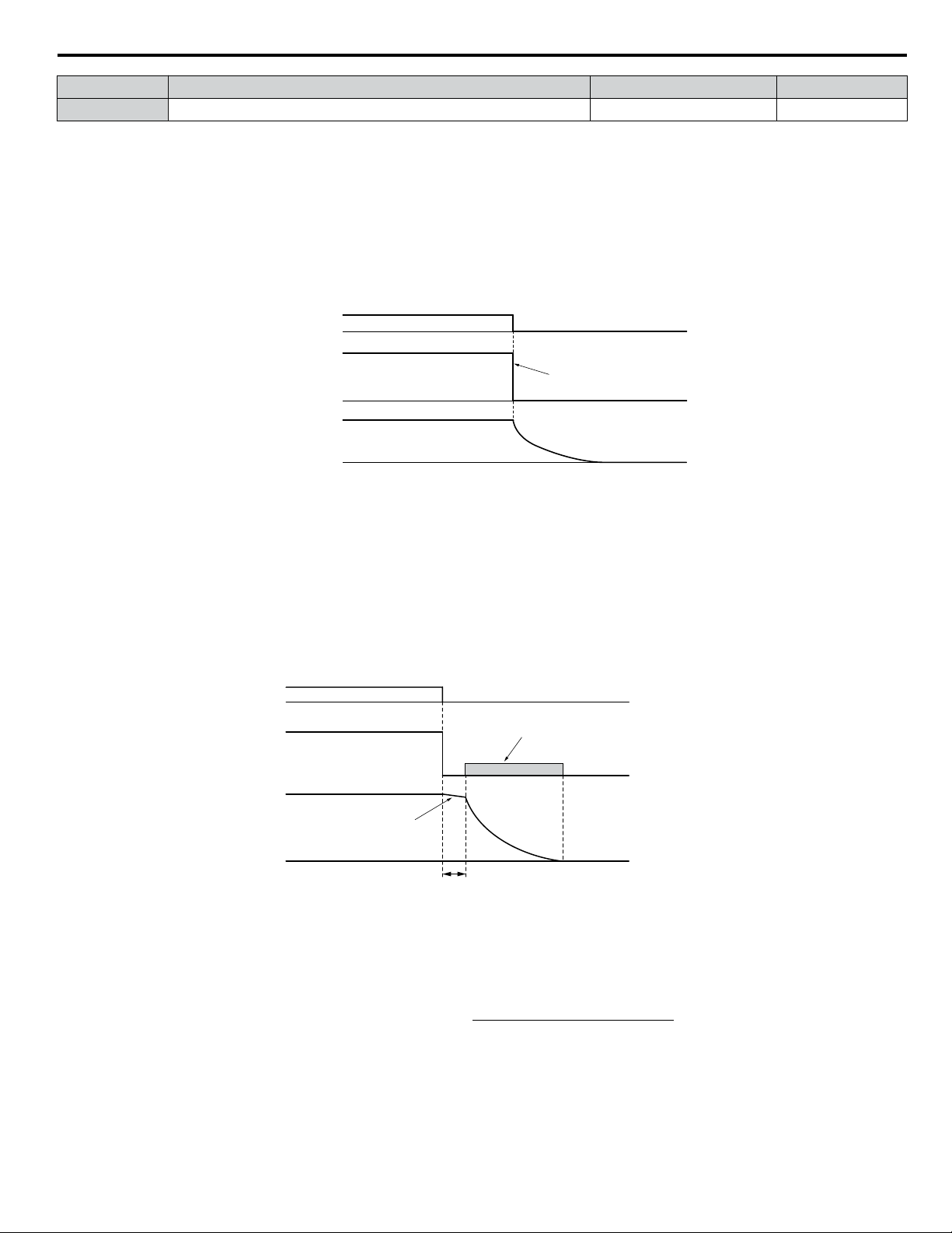
DC Injection brake time
(b2-04) x 10 x Output frequency
Max. output frequency (E1-04)
=
i.6 Start-Up Programming and Operation
No. Parameter Name Setting Range Default
b1-03 Stopping Method Selection 0 to 3 1
Setting 0: Ramp to Stop
When the Run command is removed, the drive will decelerate the motor to stop. The deceleration rate is determined by the
active deceleration time. The default deceleration time is set to parameter C1-02.
When the output frequency falls below the level set in parameter b2-01, the drive will start DC injection, Zero Speed Control,
or Short Circuit Braking.
Setting 1: Coast to Stop
When the Run command is removed, the drive will shut off its output and the motor will coast (uncontrolled deceleration) to
stop. The stopping time is determined by the inertia and the friction in the driven system.
Run
command
Output
frequency
Motor speed
ON OFF
Drive output is shut off
Figure i.34 Coast to Stop
Note: After a stop is initiated, any subsequent Run command entered will be ignored until the minimum baseblock time (L2-03) has expired. Do
not enter Run command until it has come to a complete stop. Use DC Injection at Start or Speed Search to restart the motor before it has
completely stopped.
Setting 2: DC Injection Braking to Stop
When the Run command is removed, the drive will enter baseblock (turn off its output) for the minimum baseblock time
(L2-03). When the minimum baseblock time has expired, the drive will inject the amount DC Injection Braking is set in
parameter b2-02 into the motor windings to brake the motor. The stopping time in DC Injection Braking to Stop is significantly
faster compared to Coast to Stop.
Run
command
Output
frequency
Motor speed
ON OFF
DC Injection Braking
with the current set in
b2-02
Motor coasts
Minimum Baseblock
Time (
L2-03)
Figure i.35 DC Injection Braking to Stop
DC Injection Braking time is determined by the value set to b2-04 and the output frequency at the time the Run command is
removed. It can be calculated by:
YASKAWA TOEP YAIQPM 02B YASKAWA AC Drive - iQpump Micro Quick Start Guide
71
Page 72

Min output
frequency
100%
(Max output
frequency)
Output frequency
when Stop command
was entered
Run wait time t
Active deceleration time
Momentary Power Loss
Minimum Baseblock
Time (L2-03)
i.6 Start-Up Programming and Operation
DC Injection braking time
b2-04×10
b2-04
10%
Output frequency when
Stop command was entered
100%
(Maximum output
frequency)
Figure i.36 DC Injection Braking Time Depending on Output Frequency
Note: If an overcurrent (oC) fault occurs during DC Injection Braking to Stop, lengthen the minimum baseblock time (L2-03) until the fault no
longer occurs.
Setting 3: Coast to Stop with Timer (Used for Back Spin Control on Vertical Turbine Pumps)
When the Run command is removed, the drive coasts to a stop. If parameter b1-11 = 0, the coast-timer (Run Delay at Stop)
becomes a value determined by a combination of output frequency and C1-02. However, if b1-11 > 0, the Run Delay at Stop
timer is set to b1-11. If the Run command is reissued during the Run Delay at Stop timer time, the drive WILL restart when
the timer expires without the need to re-cycle the Run command. The Run Delay at Stop timer will operate for both AUTO
Mode and HAND Mode. The Run Delay at Stop timer will still operate when the drive goes to sleep and then wakes up. During
the Run Delay at Stop timer execution, the HOA keypad will display a Start Delay message.
Run command
Output
frequency
ON ON ONOFF OFF
Drive output shut off
Run wait time t
Figure i.37 Coast to Stop with Timer
The wait time t is determined by the output frequency when the Run command is removed and by the active deceleration time.
Figure i.38 Run Wait Time Depending on Output Frequency
b3-01: Speed Search Selection at Start
n
Determines if Speed Search is automatically performed when a Run command is issued.
No. Parameter Name Setting Range Default
b3-01 Speed Search Selection at Start 0, 1 0
Setting 0: Disabled
This setting starts operating the drive at the minimum output frequency when the Run command is entered. If external Speed
Search 1 or 2 is already enabled by a digital input, the drive will start operating with Speed Search.
72
YASKAWA TOEP YAIQPM 02B YASKAWA AC Drive - iQpump Micro Quick Start Guide
Page 73

Output
frequency
Accel Time 1
(C1-01)
Decel Time 1
(C1-02)
Accel Time 2
(C1-03)
Decel Time 2
(C1-04)
Decel Time 1
(C1-02)
Time
FWD (REV)
Run command
ON
OFF
ON
ON
Accel/Decel Time Selection 1
(Terminals S1 to S7, H1-oo = “7”)
OFF
i.6 Start-Up Programming and Operation
Setting 1: Enabled
This setting performs Speed Search when the Run command is entered. The drive begins running the motor after Speed Search
is complete.
b5-01: PID Function Setting
n
Enables and disables the PID operation and selects the PID operation mode.
No. Parameter Name Setting Range Default
b5-01 PID Function Setting 0, 1 1
Setting 0: PID disabled
Setting 1: Output frequency = PID output 1
The PID controller is enabled and the PID output builds the frequency reference. The PID input is D controlled.
C1-01 to C1-04: Accel, Decel Times 1 and 2
n
Two different sets of acceleration and deceleration times can be set in the drive by digital inputs, motor selection, or switched
automatically.
Acceleration time parameters always set the time to accelerate from 0 Hz to the maximum output frequency (E1-04).
Deceleration time parameters always set the time to decelerate from maximum output frequency to 0 Hz. C1-01 and C1-02
are the default active accel/decel settings.
No. Parameter Name Setting Range Default
C1-01 Acceleration Time 1
C1-02 Deceleration Time 1
0.0 to 6000.0 s
<1>
C1-04 Deceleration Time 2
<1> The setting range for the acceleration and deceleration times is determined by the accel/decel time setting units in C1-10. For example, if the time
is set in units of 0.01 s (C1-10 = 0), the setting range becomes 0.00 to 600.00 s.
20.0 s
10.0 sC1-03 Acceleration Time 2
Switching Acceleration Times by Digital Input
Accel/decel time 1 is active by default if no input is set. Activate accel/decel times 2, 3, and 4 by digital inputs
(H1-oo = 7 and 1A) as explained in Table i.21.
Table i.21 Accel/Decel Time Selection by Digital Input
Accel/Decel Time Sel. 1
H1-oo = 7
Accel/Decel Time Sel. 2
H1-oo = 1A
Acceleration Deceleration
Active Times
0 0 C1-01 C1-02
1 0 C1-03 C1-04
Figure i.39 shows an operation example for changing accel/decel times. The example below requires that the stopping method
be set for “Ramp to stop” (b1-03 = 0).
Figure i.39 Timing Diagram of Accel/Decel Time Change
YASKAWA TOEP YAIQPM 02B YASKAWA AC Drive - iQpump Micro Quick Start Guide
73
Page 74

i.6 Start-Up Programming and Operation
E2-01: Motor Rated Current
n
Provides motor control, protects the motor, and calculates torque limits. Set E2-01 to the full load amps (FLA) stamped on
the motor nameplate. If Auto-Tuning completes successfully, the value entered to T1-04 will automatically be saved to E2-01.
No. Parameter Name Setting Range Default
E2-01 Motor Rated Current
<1> Display is in the following units:
BV0006 to BV0018, 2V0006 to 2V0040, and 4V0002 to 4V0023: 0.01 A units.
2V0056 to 2V0069 and 4V0031 to 4V0038: 0.1 A units.
Note: An oPE02 error will occur if the motor rated current in E2-01 is set lower than the motor no-load current in E2-03. Set E2-03 correctly to
H1-01 to H1-07: Functions for Terminals S1 to S7
n
prevent this error.
10% to 200% of the drive
rated current
<1>
Determined by
o2-04
These parameters assign functions to the multi-function digital inputs.
No. Parameter Name
H1-01 Multi-Function Digital Input Terminal S1 Function Selection 2 to B0
H1-02 Multi-Function Digital Input Terminal S2 Function Selection 2 to B0 F: Through Mode
H1-03 Multi-Function Digital Input Terminal S3 Function Selection 0 to B0 26: External Pump Fault
H1-04 Multi-Function Digital Input Terminal S4 Function Selection 0 to B0 14: Fault Reset
H1-05 Multi-Function Digital Input Terminal S5 Function Selection 0 to B0
H1-06 Multi-Function Digital Input Terminal S6 Function Selection 0 to B0
H1-07 Multi-Function Digital Input Terminal S7 Function Selection 0 to B0
<1> Number appearing in parenthesis is the default value after performing a 3-Wire initialization (A1-03 = 3330).
Setting
Range
40 (F)
8D (0)
80 (3)
81 (4)
Default
<1>
: Forward Run Command (2-Wire sequence)
<1>
: Multi Setpoint 1
<1>
: HAND Mode
<1>
: HAND Mode 2
Setting F: Not Used/Through Mode
Select this setting when using the terminal in a pass-through mode. When set to F, an input does not trigger any function in
the drive. Setting F, however, still allows the input status of the terminal (open or closed) to be read out by a PLC via a
communication option or MEMOBUS/Modbus communications. The drive input terminals can then be used as remote I/O by
the PLC.
Setting 14: Fault Reset
When the drive detects a fault condition, the fault output contact closes, the drive output shuts off, and the motor coasts to
stop (specific stopping methods can be selected for some faults such as L1-04 for motor overheat). After removing the Run
command, clear the fault either by pressing the RESET key on the digital operator or closing a digital input configured as a
Fault Reset (H1-oo = 14).
Note: Remove the Run command prior to resetting a fault. Fault Reset commands are ignored while the Run command is present.
Setting 20 to 2F: External Fault
The External fault command stops the drive when problems occur with external devices.
To use the External fault command, set one of the multi-function digital inputs to a value between 20 and 2F. The digital
operator will display EFo where o is the number of the terminal to which the external fault signal is assigned.
For example, if an external fault signal is input to terminal S3, “EF3” will be displayed.
Select the value to be set in H1-oo from a combination of any of the following three conditions:
• Signal input level from peripheral devices (N.O., N.C.)
• External fault detection method
• Operation after external fault detection
An “On-Delay” timer will be applied to the external fault if it is “Normally Open” and an “Off-Delay” timer will be applied
to the external fault if it is “Normally Closed”.
If the external fault is set to “During Run”, the time delay will start after the Run command is received.
Table i.22 shows the relationship between the conditions and the value set to H1-oo:
Terminal statuses, detection conditions, and stopping methods marked with an “O” are applicable to the corresponding settings.
74
YASKAWA TOEP YAIQPM 02B YASKAWA AC Drive - iQpump Micro Quick Start Guide
Page 75

S1
S2
SN
Drive
Forward Run
Reverse Run
Standard Digital
Input Common
i.6 Start-Up Programming and Operation
Table i.22 Stopping Method for External Fault
Terminal Status
Setting
20 O O O
21 O O O
22 O O O
23 O O O
24 O O O
25 O O O
26 O O O
27 O O O
28 O O O
29 O O O
2A O O O
2B O O O
2C O O O
2D O O O
2E O O O
2F O O O
<1> Determine the terminal status for each fault, i.e., whether the terminal is normally open or normally closed.
<2> Determine whether detection for each fault should be enabled only during run or always detected.
N.O. N.C.
<1>
Detection Conditions
Always
Detected
during Run
<2>
Detected
only
Ramp to Stop
(fault)
Stopping Method
Coast to Stop
(fault)
Fast Stop
(fault)
Alarm Only
(continue
running)
Settings 40, 41: Forward Run, Reverse Run Command for 2-Wire Sequence
Configures the drive for a 2-Wire sequence.
When an input terminal set to 40 closes, the drive operates in the forward direction. When an input set for 41 closes, the drive
operates in reverse. Closing both inputs simultaneously will result in an external fault.
Note: 1. This function cannot be used simultaneously with settings 42 and 43.
2. The same functions are assigned to terminals S1 and S2 when the drive is initialized for 2-Wire sequence.
Figure i.40 Example Wiring Diagram for 2-Wire Sequence
Setting 80: HAND Mode
Closing this input will put the drive in HAND Mode.
If this contact is closed within one second of power-up, the drive will honor the utility delay time.
Note: When inputs 80 and 81 are closed simultaneously, input 80 has priority and P5-01 determines the frequency reference.
Setting 81: HAND Mode 2
Closing this input will put the drive in HAND Mode using P5-05 as a frequency reference.
If this contact is closed within one second of power-up, the drive will honor the utility delay time.
Note: When inputs 80 and 81 are closed simultaneously, input 80 has priority and P5-01 determines the frequency reference.
Settings 8D and 8E: Multi Setpoints 1 and 2
Settings 8D and 8E will override all other PID setpoints when closed.
YASKAWA TOEP YAIQPM 02B YASKAWA AC Drive - iQpump Micro Quick Start Guide
75
Page 76

i.6 Start-Up Programming and Operation
Table i.23 Multi Setpoints 1 and 2
Multi Setpoint 1
(H1-0o = 8D)
Open Open
Closed Open Set Point 2 – Q1-02
Open Closed Set Point 3 – Q1-03
Closed Closed Set Point 4 – Q1-04
H2-01 to H2-03: Terminal MA/MB/MC, P1/PC, and P2/PC Function Selection
n
Multi Setpoint 2
(H1-0o = 8E)
Setpoint Source
Frequency Ref (dependent on b1-01), Set-Point 1
- Q1-01 (when b1-01 = 0), Analog Setpoint
(H3-0o = C), Pulse Input Setpoint (H6-01 = 2),
or Memobus setpoint.
The drive has three multi-function output terminals.
No. Parameter Name Setting Range Default
H2-01 Terminal MA, MB and MC Function Selection (relay) 0 to 1AA E: Fault
H2-02 Terminal P1 Function Selection (open-collector) 0 to 1AA 37: During Frequency Output
H2-03 Terminal P2 Function Selection (open-collector) 0 to 1AA E: Fault
Setting E: Fault
The output closes when the drive faults (excluding CPF00 and CPF01 faults).
Setting 37: During Frequency Output
The output closes when the drive is outputting a frequency.
Status Description
Open Drive is stopped or one of the following functions is being performed: baseblock, DC Injection Braking, Short Circuit Braking.
Closed Drive is outputting frequency.
ON
OFF
OFF
ONOFF
OFF
Figure i.41 During Frequency Output Time Chart
ON
ON
P1-01: Pump Mode
n
run command
baseblock
command
output
frequency
during run
during frequency
output
Selects the base operation mode of the drive controller.
No. Parameter Name Setting Range Default
P1-01 Pump Mode 0, 3 0
Setting 0: Drive only
Designed for single pump stand-alone applications
Setting 3: MEMOBUS network
Up to eight drives can be networked together to provide for system redundancy and precise control.
Staging is disabled when and the drive PID output is influenced by the Water Level / Suction Pressure Control.
The functions listed below will behave slightly different when P1-01 is set to 3:
• Start Level: Active on the first pump in the network. Drives in the process of alternation will not undergo this process.
• Sleep: Active when the drive is the only drive running on the network.
76
YASKAWA TOEP YAIQPM 02B YASKAWA AC Drive - iQpump Micro Quick Start Guide
Page 77

i.6 Start-Up Programming and Operation
• Over-cycle Protection: Active when the drive is the only drive running on the network.
• Pre-charge: Active only on the first drive to run in the network.
• Low City Pressure: Active on any drive in the network. An alarm condition will cause other drives in the network to stop
running and show a “Net Pump Err” message.
• Utility Delay: When this function is active, the drive is unavailable to the iQpump MEMOBUS Network and will force the
Home Screen text to show “Pump Off Network”.
• Remote Drive Disable: When this function is active, the drive is unavailable to the iQpump MEMOBUS Network and will
force the Home Screen text to show “Pump Off Network”.
P1-02: System Units
n
Selects the base unit in which most drive PID setpoints, scaling, monitors, limits, and faults/alarm levels will be set.
Note: Set this parameter prior to changing other parameters, as internal scaling is based on P1-02.
No. Parameter Name Setting Range Default
P1-02 System Units 0 to 10 1
Setting 0: No unit
Setting 1: PSI: Pounds per square inch
Setting 2: Pa: Pascals
Setting 3: Bar: Bar
Setting 4: "WC: Inch of water
Setting 5: "Hg: Inch of Mercury
Setting 6: ft: feet
Setting 7: m: meters
Setting 8: °F: Degrees Fahrenheit
Setting 9: °C: Degrees Celsius
Setting 10: Percent
P1-03: Feedback Device Scaling
n
Sets the feedback device scaling used for the PID controller. This information can be found on the nameplate or specification
sheet and is usually expressed as the maximum output of the device.
For example, a pressure sensor scaling might be 145.0 PSI at 20 mA output and would require setting P1-03 to 145.0 PSI.
Note: Set this parameter prior to changing other parameters related to the PID feedback, as internal scaling is based on P1-03.
No. Parameter Name Setting Range Default
P1-03 Feedback Device Scaling 0.1 to 6000.0 145.0 PSI
P1-04: Start / Draw Down Level
n
Sets the wake up level from the Sleep function. This setting is dependent on whether PID is normal or inverse acting (b5-09).
When the drive is asleep and the PID feedback signal rises above (normal acting) or falls below (inverse acting) this setting
for the time set in P1-05, Start Level Delay Time, the drive will wake up.
No. Parameter Name Setting Range Default
P1-04 Start / Draw Down Level -999.9 to 999.9 0.0 PSI
Q1-01: PID Controller Setpoint 1
n
Sets the PID setpoint for the controller. The drive will use the system feedback signal and modulate the pump speed to regulate
the feedback at the Q1-01 setpoint. The units for Q1-01 are selected by b1-01 and the scaling is set in parameter P1-03. This
parameter is active when b1-01 (Reference Source) is set to 0 (HOA keypad).
No. Parameter Name Setting Range Default
Q1-01 PID Controller Setpoint 1 0.0 to 6000.0 0.0 PSI
YASKAWA TOEP YAIQPM 02B YASKAWA AC Drive - iQpump Micro Quick Start Guide
77
Page 78

i.7 Troubleshooting
i.7 Troubleshooting
NOTICE
Refer to the iQpump Micro User Manual TOEP YAIQPM 03 for complete information on Troubleshooting causes and
solutions.
The iQpump Micro User Manual is posted on the Yaskawa website, www.yaskawa.com.
u
Fault Detection
Note: Digital operator display text is represented in the tables below using standard font for both LCD displays and LED displays. When using
Fault Displays
n
Digital Operator
Anti-Jam Fault
CPF20 or CPF21 One of the following faults occurred: RAM fault, FLASH memory error, watchdog circuit exception, clock error
the standard LED operator, however, display text will appear in 7-segment LED (ex: “ ”). When the LED fault display differs from the
LCD display, the LED display text will be shown in parentheses under the LCD display text.
Display
AJF
(AJF)
<1>
bUS
CE
CPF02
CPF03
CPF06
<1>
CPF07
CPF08
CPF11 RAM Fault
CPF12
CPF13
CPF14
CPF16
CPF17
CPF18
CPF19
Anti-Jam Fault
Option Communication Error
• The connection was lost after establishing initial communication.
• Only detected when the run command frequency reference is assigned to an option card.
MEMOBUS/Modbus Communication Error
Control data was not received for the CE detection time set to H5-09.
A/D Conversion Error
An A/D conversion error or control circuit error occurred.
PWM Data Error
There is a problem with the PWM data.
EEPROM Memory Data Error
Error in the data saved to EEPROM
Terminal Board Communications Error
A communication error occurred at the terminal board.
EEPROM Serial Communication Fault
EEPROM communications are not functioning properly.
FLASH Memory Fault
Problem with the ROM (FLASH memory).
Watchdog Circuit Exception
Self-diagnostics problem.
Control Circuit Fault
CPU error (CPU operates incorrectly due to noise, etc.)
Clock Fault
Standard clock error.
Timing Fault
A timing error occurred during an internal process.
Control Circuit Fault
CPU error. Non-Maskable Interrupt (An unusual interrupt was triggered by noise, etc.)
Control Circuit Fault
CPU error (Manual reset due to noise, etc.)
Fault Name
78
YASKAWA TOEP YAIQPM 02B YASKAWA AC Drive - iQpump Micro Quick Start Guide
Page 79

i.7 Troubleshooting
Digital Operator
Display
CPF22
CPF23 PWM Feedback Fault
CPF24
<1>
CPF25 Terminal Board Not Connected
CPF26 to CPF35
CPF40 to CPF43
E5
EF0
EF1
EF2
EF3
EF4
EF5
EF6
EF7
A/D Conversion Fault
A/D conversion error.
Drive Unit Signal Fault
The drive capacity cannot be detected correctly (drive capacity is checked when the drive is powered up).
Control Circuit Error
CPU error
SI-T3 Watchdog Timer Error
The watchdog timed out.
Option Card External Fault
An external fault condition is present.
Pump Fault (input terminal S1)
External fault at multi-function input terminal S1.
Pump Fault (input terminal S2)
External fault at multi-function input terminal S2.
Pump Fault (input terminal S3)
External fault at multi-function input terminal S3.
Pump Fault (input terminal S4)
External fault at multi-function input terminal S4.
Pump Fault (input terminal S5)
External fault at multi-function input terminal S5.
Pump Fault (input terminal S6)
External fault at multi-function input terminal S6.
Pump Fault (input terminal S7)
External fault at multi-function input terminal S7.
Fault Name
EEPROM Write Error
Err
Data cannot be written to the EEPROM
FAn Internal Cooling Fan Failure
FDBKL Wire Break
(FDB-L)
GF
HFB
HWL
(HIH20)
LF
LF2
LFB
LOP
PID Feedback Loss
The analog input programmed for PID feedback has risen above 21 mA or fallen below 3 mA.
Ground Fault
• A current short to ground exceeded 50% of rated current on the output side of the drive.
• Setting L8-09 to 1 enables ground fault detection in models 2V0020 to 2V0069 and 4V0011 to 4V0038.
High Feedback
The feedback signal is too high.
High Water Level
The “High Water Level” digital input is active (H1-0o = 90).
Output Phase Loss
• Phase loss on the output side of the drive.
• Setting L8-07 to 1 or 2 enables Phase Loss Detection.
Output Current Imbalance
One or more of the phases in the output current are lost.
Low Feedback
The feedback signal is too low.
Loss of Prime
The pump has lost its prime.
YASKAWA TOEP YAIQPM 02B YASKAWA AC Drive - iQpump Micro Quick Start Guide
79
Page 80

i.7 Troubleshooting
Digital Operator
Display
LWL
(LOH20)
MSL
Net Master Lost
(NSL)
NMS
(NOTSP)
nSE
oC
oFA00
<1>
oFA01
oFA03, oFA04 Option Card Error Occurred at Option Port CN5
oFA30 to oFA43 Communication Option Card Connection Error (CN5)
oH
oH1
oH4
oL1
oL2
oL3
oL4
oL5
oPr
ov
PF
PoC Pump Over Cycle
rH
Low Water Level
The “Low Water Level” digital input is active (H1-0o = 8F).
Net Master Lost
The MEMOBUS master has been lost
Not Maintaining Setpoint
The setpoint cannot be maintained and P1-17 is set to 0.
Node Setup Error
A terminal assigned to the node setup function closed during run.
Overcurrent
Drive sensors detected an output current greater than the specified overcurrent level.
Option Card Connection Error at Option Port CN5
Option compatibility error
Option Card Fault at Option Port CN5
Option not properly connected
Heatsink Overheat
The heatsink temperature exceeded the overheat pre-alarm level set to L8-02.
Overheat 1 (Heatsink Overheat)
The heatsink temperature exceeded the drive overheat level.
Motor Overheat Fault (PTC Input)
• The motor overheat signal to analog input terminal A1 or A2 exceeded the fault detection level.
• Detection requires setting multi-function analog inputs H3-02 or H3-10 to E.
Motor Overload
The electronic motor overload protection tripped
Drive Overload
The thermal sensor of the drive triggered overload protection.
Overtorque Detection 1
The current has exceeded the value set for Torque Detection Level 1 (L6-02) for longer than the allowable time (L6-03).
Overtorque Detection 2
The current has exceeded the value set for Torque Detection Level 2 (L6-05) for longer than the allowable time (L6-06).
Mechanical Weakening Detection 1
Overtorque occurred, matching the conditions specified in L6-08.
External Operator Connection Fault
The external operator has been disconnected from the drive.
Note: An oPr fault will occur when all of the following conditions are true:
• Output is interrupted when the keypad is disconnected (o2-06 = 1).
• The Run command is assigned to the operator (b1-02 = 0 and HAND has been selected).
Overvoltage
Voltage in the DC bus has exceeded the overvoltage detection level.
• For 200 V class drives: approximately 410 V
• For 400 V class drives: approximately 820 V (740 V when E1-01 is less than 400)
Input Phase Loss
Drive input power has an open phase or has a large imbalance of voltage between phases. Detected when L8-05 is set 1
(enabled).
Braking Resistor Overheat
Braking resistor protection was triggered.
Fault detection is enabled when L8-01 = 1 (disabled as a default).
Fault Name
80
YASKAWA TOEP YAIQPM 02B YASKAWA AC Drive - iQpump Micro Quick Start Guide
Page 81

i.7 Troubleshooting
Digital Operator
Display
rr
SC IGBT Short Circuit or Ground Fault
SEr
Single Phase Foldback
(1PH)
TIE Time Interval Error
UL3
UL4
UL6
Underload Det 6
Uv1
<1>
Uv2
<1>
Uv3
<1>
VLTS Volute-Thermostat Fault
<1> Fault history is not kept for this fault.
Dynamic Braking Transistor
The built-in dynamic braking transistor failed.
Too Many Speed Search Restarts
The number of Speed Search restarts exceeded the value set to b3-19.
Single Phase Foldback
Output speed is being limited because of excessive DC Bus voltage ripple.
Undertorque Detection 1
The current has fallen below the minimum value set for Torque Detection Level 1 (L6-02) for longer than the allowable time
(L6-03).
Undertorque Detection 2
The current has fallen below the minimum value set for Torque Detection Level 2 (L6-05) for longer than the allowable time
(L6-06).
Motor Underload
The load has fallen below the underload curve defined in L6-14.
Control Circuit Undervoltage Fault
One of the following conditions occurred while the drive was running:
• Voltage in the DC bus fell below the undervoltage detection level (L2-05).
• For 200 V class: approximately 190 V (160 V for single phase drives)
• For 400 V class: approximately 380 V (350 V when E1-01 is less than 400) The fault is output only if L2-01 = 0 or L2-01
= 1 and the DC bus voltage is under L2-05 for longer than L2-02.
The fault is output only if L2-01 is set to 0 or 1 and the DC bus voltage has fallen below the level set to L2-05 for longer than
the time set to L2-02.
Control Power Supply Voltage Fault
Voltage is too low for the control drive input power.
Undervoltage 3 (Soft-Charge Bypass Relay Fault)
The soft-charge bypass relay failed.
Fault Name
u
Alarm Detection
Note: Digital operator display text is represented in the tables below using standard font for both LCD displays and LED displays. When using
Alarm Codes
n
the standard LED operator, however, display text will appear in 7-segment LED (ex: “ ”). When the LED fault display differs from the
LCD display, the LED display text will be shown in parentheses under the LCD display text.
An alarm is indicated by a code on the data display and the flashing ALM LED. The drive output is not necessarily switched
off.
To remove an alarm, trace and remove the cause, and reset the drive by pushing the Reset key on the operator or cycle the
power supply.
Digital Operator
Display
AEr
AnalogFB Lost
Switched to Net
(AFBL)
Anti-Jam Active
(AJA)
bAT Digital Operator Battery Voltage Low
bb
Station Address Setting Error (CC-Link, CANopen, MECHATROLINK)
Option card node address is outside of the acceptable setting range.
Analog Feedback Lost
Analog feedback has not been detected and the network PI feedback signal is now used.
Anti-Jam Alarm
Baseblock
Drive output interrupted as indicated by an external baseblock signal.
Alarm Name
YASKAWA TOEP YAIQPM 02B YASKAWA AC Drive - iQpump Micro Quick Start Guide
81
Page 82

i.7 Troubleshooting
Digital Operator
Display
bUS
CALL
CE
CrST Cannot Reset
CyC
dnE Drive Disabled
E5
EF
EF0
EF1
EF2
EF3
EF4
EF5
EF6
EF7
EoF Emergency Override Forward Run
Eor Emergency Override Reverse Run
FAn Internal Cooling Fan Error
Hbb
HbbF
Feedback Loss Go To
Freq. b5-13
(FLGT)
Feedback Loss Wire
Break
(FDB-L)
Freq. Ref Pump Min
(P1-06)
(PFREF)
Freq. Ref Thrust (P4-12)
(PTHRT)
HCA
Alarm Name
Option Communication Error
• The connection was lost after establishing initial communication.
• Only detected when the run command frequency reference is assigned to an option card.
Serial Communication Transmission Error
Communication has not yet been established.
MEMOBUS/Modbus Communication Error
Control data was not received for the CE detection time set to H5-09.
MECHATROLINK Comm. Cycle Setting Error
Comm. Cycle Setting Error was detected.
SI-T3 Watchdog Timer Error
The watchdog timed out.
Forward/Reverse Run Command Input Error
Both forward run and reverse run closed simultaneously for longer than 0.5 s.
Option Card External Fault
An external fault condition is present.
Pump Fault (input terminal S1)
External fault at multi-function input terminal S1.
Pump Fault (input terminal S2)
External fault at multi-function input terminal S2.
Pump Fault (input terminal S3)
External fault at multi-function input terminal S3.
Pump Fault (input terminal S4)
External fault at multi-function input terminal S4.
Pump Fault (input terminal S5)
External fault at multi-function input terminal S5.
Pump Fault (input terminal S6)
External fault at multi-function input terminal S6.
Pump Fault (input terminal S7)
External fault at multi-function input terminal S7.
Safe Disable Signal Input
Both Safe Disable Input channels are open.
Safe Disable Signal Input
One Safe Disable channel is open while the other channel is closed.
PI Feedback Loss
The drive will run at the speed set in b5-13, Feedback Loss Goto Frequency.
PI Feedback Loss
The analog input programmed for PID feedback has gone above 21 mA or fallen below 3 mA.
Minimum Pump Frequency Reference
Drive frequency reference is set lower than P1-06, Minimum Pump Frequency.
Thrust Frequency Reference
The fixed frequency reference is set to a value lower than the P4-12, Thrust Frequency, setting.
Current Alarm
Drive current exceeded overcurrent warning level (150% of the rated current).
82
YASKAWA TOEP YAIQPM 02B YASKAWA AC Drive - iQpump Micro Quick Start Guide
Page 83

i.7 Troubleshooting
Digital Operator
Display
High Feedback High FB
Sensed
(HIFB)
LOP
Low City Pressure
(LCP)
Low Feedback Low FB
Sensed
(LoFb)
Low Suction Pressure
(LSP)
Low Water in Tank
(LWT)
LT-1
LT-2
LT-3
LT-4
NETSCAN
Waiting for Master
(NETSC)
NMS
(NOTSP)
oH
oH2
oH3
oL1
oL2
oL3
oL4
ov
PCyC Pump Over Cycle
Alarm Name
High Feedback Level Alarm
The feedback signal is too high.
Loss of Prime
The pump has lost its prime and P1-22 is set to 1.
Low City Pressure
Low Feedback Level Alarm
The feedback signal is too low.
Low Suction Pressure
Low Water in Tank
Cooling Fan Maintenance Time
The cooling fan has reached its expected maintenance period and may need to be replaced.
Note:
Capacitor Maintenance Time
The main circuit and control circuit capacitors are nearing the end of their expected performance life.
Note:
Soft Charge Bypass Relay Maintenance Time
The DC bus soft charge relay is nearing the end of its expected performance life.
Note:
IGBT Maintenance Time (50%)
IGBTs have reached 50% of their expected performance life.
Note:
NETSCAN
Drive is waiting for a message from the master.
Not Maintaining Setpoint
The setpoint cannot be maintained and P1-17 is set to 1.
Heatsink Overheat
The temperature of the heatsink exceeded the overheat pre-alarm level set to L8-02.
Heatsink Overheat Warning
“Heatsink Overheat Warning” was input to a multi-function input terminal, S1 through S7 (H1-oo= B).
Motor Overheat
The motor overheat signal entered to a multi-function analog input terminal exceeded the alarm level (H3-02 or H3-10 = E).
Motor Overload
The electronic motor overload protection tripped
Drive Overload
The thermal sensor of the drive triggered overload protection.
Overtorque Detection 1
The current has exceeded the value set for Torque Detection Level 1 (L6-02) for longer than the allowable time (L6-03).
Overtorque Detection 2
The current has exceeded the value set for Torque Detection Level 2 (L6-05) for longer than the allowable time (L6-06).
Control Circuit Overvoltage
Voltage in the control circuit exceeded the trip point.
• For 200 V class drives: approximately 410 V
• For 400 V class drives: approximately 820 V (740 V when E1-01 < 400)
An alarm output (H2-oo = 10) will only be triggered if both (H2-oo = 2F and
H2-oo = 10) are set.
An alarm output (H2-oo = 10) will only be triggered if H2-oo = 2F.
An alarm output (H2-oo = 10) will only be triggered if H2-oo = 2F.
An alarm output (H2-oo = 10) will only be triggered if H2-oo = 2F.
YASKAWA TOEP YAIQPM 02B YASKAWA AC Drive - iQpump Micro Quick Start Guide
83
Page 84

i.7 Troubleshooting
Digital Operator
Display
R-DNE-So
(Rdd)
SE
TdE Time Data Error
TrPC
UL3
UL4
UL6
Underload Det 6
Uv
u
Operator Programming Errors
Remote Drive Disable
MEMOBUS/Modbus Communication Test Mode Error
Note: This alarm will not trigger a multi-function output terminal that is set for alarm output
(H2-oo = 10).
IGBT Maintenance Time (90%)
IGBTs have reached 90% of their expected performance life.
Undertorque Detection 1
The current has fallen below the minimum value set for Torque Detection Level 1 (L6-02) for longer than the allowable time
(L6-03).
Undertorque Detection 2
The current has fallen below the minimum value set for Torque Detection Level 2 (L6-05) for longer than the allowable time
(L6-06).
Motor Underload
The load has fallen below the underload curve defined in L6-14.
Control Circuit Undervoltage
One of the following conditions occurred:
• Contactor to suppress inrush current in the drive was opened.
• Low voltage in the control drive input power. This alarm outputs only if L2-01 is not 0 and DC bus voltage is under L2-05.
Alarm Name
oPE Codes
n
An Operator Programming Error (oPE) occurs when a contradictory parameter is set or an individual parameter is set to an
inappropriate value.
The drive will not operate until the parameter or parameters causing the problem are set correctly. An oPE, however, does not
trigger an alarm or fault output. When an oPE appears on the operator display, press the ENTER button to view U1-18 and
see which parameter is causing the oPE.
Digital Operator
Display
oPE01
oPE02
oPE03
oPE04 Initialization Required, Term <–> Ctrl Chg
oPE05 Run Command/Frequency Reference Source Selection Error
oPE07
oPE08
oPE09
oPE10
oPE11
oPE33
Net Incompatible
Drive Capacity Setting Fault
Drive capacity and the value set to o2-04 do not match.
Parameter Range Setting Error
Use U1-18 to find parameters set outside the range.
Multi-Function Input Selection Error
A contradictory setting is assigned to multi-function contact inputs H1-01 to H1-07.
Multi-Function Analog Input Selection Error
A contradictory setting is assigned to multi-function analog inputs H3-02 or H3-06 and PID functions conflict.
Parameter Selection Error
A function has been set that cannot be used in the motor control method selected.
PID Control Selection Fault
PID control function selection is incorrect. Requires that PID control is enabled (b5-01 = 1).
V/f Data Setting Error
One of the following setting errors has occurred:
E1-09 ≤ E1-07 < E1-06 ≤ E1-11 ≤ E1-04
Carrier Frequency Setting Error
Correct the setting for the carrier frequency.
Parameter selection is incompatible with the selected network P9-99
Error Name
84
YASKAWA TOEP YAIQPM 02B YASKAWA AC Drive - iQpump Micro Quick Start Guide
Page 85

i.7 Troubleshooting
u
Digital Operator Display Messages
Table i.24 lists messages and errors that may appear during normal pump operation.
These messages do not trigger multi-function output terminals that have been set up to close when a fault or alarm occurs.
Table i.24 Digital Operator Display Messages
HOA Keypad Display
(LED Operator Display)
CrST
Cannot Reset
(CrST)
Current Limit Foldback
(CUr)
De-staging in X sec
(dSTgE)
DigitalOut Delay Active
(no indication)
Feedback Drop Check
(FbCH-)
LOCK
Parameter Locked
(LoC-P)
Lube Pump Active
(no indication)
Net Pump Err
Chk Faulted Pump
(nETEr)
Net Start Delay
P9-29 Active
(nETST)
Network FB Lost
Check FB Source
(nETFb)
PASS
MEMOBUS/Modbus Comm. Test
Mode Complete
(PASS)
Pre Chg Mode
Exit in Xsec
(PrCHg)
Single Phase Foldback
(1PH)
Sleep Active Wait for Start
(SLEEP)
Sleep Boost Active
(booST)
Staging in X sec
(STAgE)
Start Delay Adjust b1-11
(WAIT)
Start Delay Timer Active
(WAIT)
Thrust Mode
Thrust Active
(THrST)
Utility Delay Adjust by P4-17
(UTIL)
Fault reset was being executed when a Run command was entered. Ensure that a Run command cannot be entered
from the external terminals or option during fault reset. Turn off the Run command.
Displayed when drive output speed is being limited due to the output current limit. Reduce the load or replace
with higher capacity drive.
Displayed during multiplexing when drive de-staging is in progress. X sec indicates the time left before the destaging takes place.
Displayed when the Digital Output Delay function is active.
Displayed when the drive is determining whether the feedback will change abruptly when the drive enters Sleep
Mode. Drop Level is configured by P2-08, Delta Sleep Feedback Drop Level, and P2-09 Feedback Detection
Drop Time.
Displayed after an attempt to change a parameter when A1-01 = 3. Unlock the keypad by setting A1-01 = 2.
Displayed when the Lube Pump digital output is energized.
Displayed when the drive has been stopped because another drive in the network has a system fault or a Low City
Pressure alarm.
Displayed when the MEMOBUS network is waiting for the P9-29 timer to elapse.
Displayed when no valid analog PI feedback source can be found on the network and network PI feedback has
been lost.
MEMOBUS/Modbus test has finished normally.
Pre-charge 1 or 2 active. X indicates time left before pre-charge exits due to timers (P4-03 + P4-07).
Displayed when an input phase has been lost, or when excess load is being drawn by the motor in a single phase
application.
Displayed when the drive is in Sleep Mode or when the drive is waiting for the feedback level to reach the level
set in P1-04, Start Level.
Displayed when the drive entering Sleep Mode and the pressure setpoint is being boosted. During this time, the
U1-01, Frequency Reference, monitor will be updated with the boosted setpoint.
Displayed during multiplexing when drive staging is in progress. X sec indicates the time left before the staging
takes place.
Displayed when the drive start is being delayed by Coast to Stop with Timer (Back Spin Timer). This time is
adjusted by parameter b1-11, Coast to Stop with Timer Time.
Displayed when the feedback level has reached the level set in P1-04, Start Level, and the Start Delay timer is
incrementing.
Displayed during Thrust Mode.
Displayed when the drive is delaying the Run command due to the Utility Start Delay Function.
Description
YASKAWA TOEP YAIQPM 02B YASKAWA AC Drive - iQpump Micro Quick Start Guide
85
Page 86

F2F1
ESC
M M
AUTO OFF
ENTERRESET
-DRIVE-
U1- 01=60.00Hz
----------------
U1- 02=60.00Hz
JOG FWD FWD/REV
-Rdy-
ALM
DIGITAL OPERATOR JVOP-183
HAND
Freq Ref (OPR)
i.7 Troubleshooting
u
Fault Reset Methods
After the Fault Occurs Procedure
Press
on the digital operator.
Fix the cause of the fault, restart the
drive, and reset the fault
Press on the optional HOA keypad.
Fix the cause of the fault and reset via
Fault Reset Digital Input S4.
Close then open the fault signal digital input via
terminal S4. S4 is set to fault reset as default
(H1-04 = 12).
Turn off the main power supply if the above methods do not reset the fault. Reapply power
after the digital operator display has turned off.
Fault Reset Switch
2
1
Drive
S4 Fault Reset Digital Input
SC Digital Input Common
ON
OFF
86
YASKAWA TOEP YAIQPM 02B YASKAWA AC Drive - iQpump Micro Quick Start Guide
Page 87

i.8 Drive Specifications
i.8 Drive Specifications
Note: For optimum performance life of the drive, install the drive in an environment that meets the required specifications.
Item Specification
Control Method V/f Control (V/f)
Frequency Control Range 0.01 to 400 Hz
Digital input: within ±0.01% of the max output frequency
(-10 to +50 °C)
Analog input: within ±0.5% of the max output frequency
(25 °C ±10 °C)
Digital inputs: 0.01 Hz
Analog inputs: 1/1000 of maximum output frequency
1/220 x Maximum output frequency (E1-04)
Main frequency reference: 0 to +10 Vdc (20 kΩ), 4 to 20 mA (250 Ω), 0 to 20 mA (250 Ω)
Main speed reference: Pulse Train Input (max 32 kHz)
Instantaneous Average Decel Torque
1.5 kW: over 50%, 2.2 kW and above: over 20%
Continuous Regen Torque: 20%,
125% with a Braking Resistor Unit
Momentary Power Loss Ride-Thru
Speed Search
Over/Undertorque Detection
Multi-Step Speed (17 steps max)
Accel/Decel Time Switch
S-Curve Accel/Decel,
2-Wire/3-Wire Sequence
Stationary Auto-Tuning of Line-to-Line Resistance
Dwell
Cooling Fan ON/OFF
Slip Compensation
Torque Compensation
Jump Frequencies (reference dead band)
Frequency Reference Upper/Lower Limit
DC Injection Braking (start and stop)
PID Control (with Sleep Function)
MEMOBUS/Modbus (RS-485/RS-422 Max 115.2 kbps)
Fault Reset
Parameter Copy
Fault Restart
Removable Terminals with Parameter Backup Function
Drive stops when output current is 120% rated current for 60 sec.
200 V Class: Stops when DC bus voltage exceeds approx. 410 V
400 V Class: Stops when DC bus voltage exceeds approx. 820 V
Drive stops when DC bus voltage falls below the levels indicated:
190 V (3-phase 200 V), 160 V (single-phase 200 V), 380 V (3-phase 400 V), 350 V (3-phase
380 V)
3 selections available: Ride-Thru disabled (stops after 15 ms), time base of 0.5 s, and continue
running as long as the drive control board is powered up.
<1>
: 0.1/0.2 kW: over 150%, 0.4/0.75 kW: over 100%,
<2>
: (10% ED) 10 s with an internal braking resistor.
<4>
Control
Character-
istics
Protection
Functions
Frequency Accuracy
Frequency Setting Resolution
Output Frequency Calculation
Resolution
Frequency Setting Signal
Starting Torque V/f: 150% at 3 Hz
Speed Control Range 1:40 (V/f Control)
Accel/Decel Time 0.00 to 6000.0 s (allows four separate settings for accel and decel)
Braking Torque
V/f Characteristics Preset V/f patterns and user-set program available.
Functions
Motor Protection Motor overheat protection via output current sensor
Overcurrent Protection Drives stops when output exceeds 170% of the rated current
Overload Protection
Overvoltage Specification
Low Voltage Protection
Momentary Power Loss Ride-Thru
<3>
YASKAWA TOEP YAIQPM 02B YASKAWA AC Drive - iQpump Micro Quick Start Guide
87
Page 88

i.8 Drive Specifications
Item Specification
Heatsink Overheat Protection Protected by thermistor
Braking Resistor Overheat Protection Overheat input signal for braking resistor (Optional ERF-type, 3% ED)
Protection
Stall Prevention
Functions
Cooling Fan Failure Protection Circuit protection (“fan-lock” sensor)
Ground Fault Protection
DC Bus Charge LED Remains lit until DC bus voltage falls below 50 V
Storage/Installation Area Indoors
Ambient Temperature
Humidity 95% RH or less with no condensation
Storage Temperature -20 to +60 °C (-4 to +140 °F) allowed for short-term transport of the product
Altitude
Shock, Impact
Environment
Surrounding Area
Orientation Install the drive vertically to maintain maximum cooling effects
Standards cULus
Protective Enclosure
Cooling Method
<1> Instantaneous average deceleration torque refers to the torque required to decelerate the motor (uncoupled from the load) from the rated motor speed
down to zero in the shortest time.
<2> Ensure that Stall Prevention Selection during Deceleration is disabled (L3-04 = 0) or set to 3 when using a braking resistor or the Braking Resistor
Unit. The default setting for the stall prevention function will interfere with the braking resistor.
<3> Overload protection may be triggered when operating with 150% of the rated output current if the output frequency is less than 6 Hz.
<4> A Momentary Power Loss Ride-Thru Unit is required for 200/400 V class drives 7.5 kW and less if the application needs to continue running during
a momentary power loss up to 2 seconds.
<5> Ground protection cannot be provided under the following circumstances when a ground fault is likely in the motor windings during run: Low
ground resistance for the motor cable and terminal block; low ground resistance for the motor cable and terminal block; or the drive is powered up
from a ground short.
Stall prevention is available during acceleration, deceleration, and during run. Separate
settings for each type of stall prevention determine the current level at which stall prevention
is triggered.
Electronic circuit protection
<5>
IP20/NEMA Type 1 enclosure: -10 °C to +40 °C (14 °F to 104 °F)
IP66/NEMA Type 4X enclosure: -10 °C to +40 °C (14 °F to 104 °F)
Up to 1000 meters without derating; up to 3000 meters with output current and voltage
derating.
10 to 20 Hz: 9.8 m/s
20 to 55 Hz: 5.9 m/s
2
2
Install the drive in an area free from:
• oil mist and dust
• metal shavings, oil, water or other foreign materials
• radioactive materials
• combustible materials (e.g., wood)
• harmful gases and liquids
• excessive vibration
• chlorides
• direct sunlight
For IP66/NEMA Type 4X enclosure drives, install the drive in an environment suitable for
IP66/NEMA Type 4X enclosures:
• NEMA Type 4X – Enclosures constructed for either indoor or outdoor use to provide a
degree of protection to personnel against incidental contact with the enclosed equipment;
to provide a degree of protection against falling dirt, rain, sleet, snow, windblown dust,
splashing water, hose-directed water, and corrosion; and that will be undamaged by the
external formation of ice on the enclosure.
• IP66 – Dust-tight enclosures to not allow any dust to penetrate. The enclosure guards the
drive against powerful jetting water sprayed from any direction and is protected against
access to hazardous parts with a wire.
IP20/NEMA Type 1
IP66/NEMA Type 4X
BV0006G and BV0010G: self-cooled
BV0012G: internal cooling fan
BV0006F: self-cooled
BV0010F to BV0018F: cooling fan
2V0006F to 2V0069F: cooling fan
4V0002F to 4V0004F: self-cooled
4V0005F to 4V0038F: cooling fan
2V0006G to 2V0012G: self-cooled
2V0020G: internal cooling fan
2V0030G to 2V0069G: internal and external
cooling fans
4V0002G to 4V0005G: self-cooled
4V0007G to 4V0011G: internal cooling fan
4V0018G to 4V0038G: internal and external
cooling fans
88
YASKAWA TOEP YAIQPM 02B YASKAWA AC Drive - iQpump Micro Quick Start Guide
Page 89

i.8 Drive Specifications
u
Single-Phase Derating
iQpump Micro drives are compatible for use with both three-phase and single-phase input power supplies. The drive output
to the motor is always three-phase, regardless of number of input phases.
Output capacity to the motor is derated when using single-phase input power and the drive firmware includes protection for
single-phase input applications. This protection is enabled by default. Disabling this protection for single-phase input
applications can void warranty and result in premature failure.
Selection of larger models always results in greater output capacity to the motor when supplying the drive with three-phase
input power. However, the selection of larger models does not always yield greater output capacity when using the drive with
single-phase input power.
Several factors affect the amount of derated drive output capacity when single-phase input power is supplied to the drive:
• Single-phase input voltage level
• Motor voltage rating
• Amount of input impedance.
The tables in this section assist in model selection by considering factors that affect the amount of derating in single-phase
input power applications.
Single-Phase Input Sizing
n
The rated output current listed in the tables allows for a 120% overload for 60 seconds. Contact Yaskawa if assistance is needed
in selecting drive models with higher overload requirements. Adding more impedance than is specified will degrade
performance.
Table i.25 240 V Single-Phase Input (-5% to +10%)
Without Input Reactor With Input Reactor
Drive Model
2V0006 7.3 4.9 1.0 URX000303 7.3 4.9 1.0
2V0010 10.8 6.8 1.5 URX000307 10.8 6.8 1.5
2V0012 13.9 7.5 2.0 URX000311 13.9 7.5 2.0
2V0020 24.0 9.7 2.0 URX000319 24.0 12.3 3.0
2V0030 37.0 7.5 2.0 URX000326 37.0 15.2 3.0
2V0040 52.0 16.7 5.0 URX000329 52.0 21.0 5.0
2V0056 68.0 23.4 5.0 URX000335 68.0 27.7 7.5
2V0069 80.0 25.8 7.5 URX000335 80.0 30.8 10.0
Drive Model
4V0002 2.1 1.3 0.5 URX000292 2.1 1.7 0.5
4V0004 4.3 2.4 1.0 URX000300 4.3 2.8 1.0
4V0005 5.9 3.5 1.5 URX000304 5.9 3.9 2.0
4V0007 8.1 3.5 1.5 URX000309 8.1 5.4 2.0
4V0009 9.4 5.1 2.0 URX000308 9.4 5.5 3.0
4V0011 14.0 5.5 3.0 URX000312 14.0 7.5 3.0
4V0018 20.0 4.5 2.0 URX000316 20.0 8.7 5.0
4V0023 24.0 5.5 3.0 URX000320 24.0 10.5 5.0
4V0031 38.0 7.9 3.0 URX000327 38.0 13.5 7.5
4V0038 44.0 11.3 5.0 URX000327 44.0 16.1 10.0
Rated Input
Current (A)
Without Input Reactor With Input Reactor
Rated Input
Current (A)
Rated
Output
Current (A)
Table i.26 480 V Single-Phase Input (-5% to +10%)
Rated
Output
Current (A)
Max
Applicable
Motor (HP)
Max
Applicable
Motor (HP)
Yaskawa Reactor Part
Number
Yaskawa Reactor Part
Number
Rated Input
Current (A)
Rated Input
Current (A)
Rated
Output
Current (A)
Rated
Output
Current (A)
Motor (HP)
Applicable
Motor (HP)
Max
Applicable
Max
YASKAWA TOEP YAIQPM 02B YASKAWA AC Drive - iQpump Micro Quick Start Guide
89
Page 90

i.9 Parameter Table
i.9 Parameter Table
This parameter table shows the most important parameters. Default settings are in bold type. Refer to the User Manual for
more detailed descriptions of parameters and settings.
No. Name Description
0: English
1: Japanese
2: German
A1-00 Language Selection
A1-01 Access Level Selection
A1-03 Initialize Parameters
A1-04 Password When the value set into A1-04 does not
A1-05 Password Setting
A1-06 Application Preset
A2-01 to
A2-32
A2-33
User Parameters 1 to 32
User Parameter
Automatic Selection
Frequency Reference
b1-01
Selection 1
Run Command
b1-02
Selection 1
Stopping Method
b1-03
Selection
Reverse Operation
b1-04
Selection
Run Command
b1-07
Retention when Source
is Changed
3: French
4: Italian
5: Spanish
6: Portuguese
7: Chinese
0: View and set A1-01 and A1-04.
Uo-oo parameters can also be viewed.
1: User Parameters (access to parameters
selected by the user, A2-01 to A2-32)
2: Advanced Access (access to view and
set all parameters)
3: Lock parameters
0: No initialization
1110: User Initialize (parameter values
must be stored using parameter o2-03)
2220: 2-Wire initialization
3330: 3-Wire initialization
5550: Terminal->Control Initialize
6008: Pressure Control
6009: Pump down level
7770: General purpose
7771: Submersible motor GP operation
match the value set into A1-05, parameters
A1-01 through A1-03 and A2-01 through
A2-33 cannot be changed.
0: Pressure control
1: General purpose
2: Submersible motor GP operation
8: Pressure control
9: Pump down level
Note: This parameter is not settable. It is
used as a monitor only.
Recently edited parameters are listed here.
The user can also select parameters to
appear here for quicker access.
0: A2-01 to A2-32 are reserved for the
user to create a list of User Parameters.
1: Save history of recently viewed
parameters. Recently edited parameters
will be saved to A2-17 through A2-32 for
quicker access.
0: Operator (will also switch PID setpoint
to Q1-01)
1: Analog input terminals
2: MEMOBUS/Modbus communications
3: Option PCB
4: Pulse input (terminal RP)
0: HOA keypad
1: Digital input terminals
2: MEMOBUS/Modbus communications
3: Option PCB
0: Ramp to stop
1: Coast to stop
2: DC Injection Braking to stop
3: Coast with timer
0: Reverse enabled
1: Reverse disabled
0: Require Cycle
1: Retain Run Command
No. Name Description
0: Run command is not accepted while in
b1-08
b1-11
b1-12
b1-14 Phase Order Selection
b1-15
b1-16
b1-17
b2-01
b2-02
b2-03
b2-04
b3-01
b3-02
b3-03
b3-05
b3-06
b3-08
Run Command
Selection in
Programming Mode
Run Delay at Stop
(Back Spin Timer)
Run Delay Memory
Selection
Frequency Reference
Selection 2
Run Command
Selection 2
Run Source 2
Run Command at
Power Up
DC Injection Braking
Start Frequency
DC Injection Braking
Current
DC Injection Braking
Time at Start
DC Injection Braking
Time at Stop
Speed Search Selection
at Start
Speed Search
Deactivation Current
Speed Search
Deceleration Time
Speed Search Delay
Time
Output Current 1
during Speed Search
Current Control Gain
during Speed Search
(Speed Estimation
Type)
Programming Mode.
1: Run command is accepted while in
Programming Mode.
2: Prohibit entering Programming Mode
during run.
Sets the amount of time that the drive will
disallow the reapplication of the Run
command after the Run command is lost.
b1-11 is active for all b1-03 settings.
0: Disabled
1: Only at Stop
2: Running & Stop
Note: A JVOP-183 HOA Keypad must be
plugged into the drive for settings 1 and 2
to function. If the keypad is removed, b1-12
will function as setting 0 (Disabled).
0: Standard
1: Switch phase order (reverses the
direction of the motor)
0: Operator
1: Analog Input
2: Serial Communications
3: Option PCB
4: Pulse Input
0: Operator
1: Digital Inputs
2: Communication
3: Option PCB
0: Disregarded. A new Run command must
be issued after power up.
1: Allowed. Drive will run immediately
after power up if a Run command is
present.
Sets the frequency at which DC Injection
Braking starts when “Ramp to stop”
(b1-03 = 0) is selected.
Sets the DC Injection Braking current as a
percentage of the drive rated current.
Sets DC Injection Braking time at start.
Disabled when set to 0.00 seconds.
Sets DC Injection Braking time at stop.
0: Disabled
1: Enabled
Sets the current level at which the speed is
assumed to be detected and Speed Search is
ended. Set as a percentage of the drive rated
current.
Sets output frequency reduction time during
Speed Search.
When using an external contactor on the
output side, b3-05 delays executing Speed
Search after a momentary power loss to
allow time for the contactor to close.
Sets the current injected to the motor at the
beginning of Speed Estimation Speed
Search. Set as a coefficient for the motor
rated current.
Sets the proportional gain for the current
controller during Speed Search.
90
YASKAWA TOEP YAIQPM 02B YASKAWA AC Drive - iQpump Micro Quick Start Guide
Page 91

i.9 Parameter Table
No. Name Description
Sets the gain which is applied to the speed
b3-10
b3-14
b3-17
b3-18
b3-19
b3-24
b3-25
b4-01
b4-02
b5-01 PID Function Setting
b5-02
b5-03
b5-04 Integral Limit Setting
b5-05 Derivative Time (D) Sets D control derivative time.
b5-06 PID Output Limit
b5-07 PID Offset Adjustment
b5-08
b5-09
b5-10
b5-11
b5-12
b5-13
b5-14
Speed Search
Detection
Compensation Gain
Bi-Directional Speed
Search Selection
Speed Search Restart
Current Level
Speed Search Restart
Detection Time
Number of Speed
Search Restarts
Speed Search Method
Selection
Speed Search Wait
Time
Timer Function OnDelay Time
Timer Function OffDelay Time
Proportional Gain
Setting (P)
Integral Time Setting
(I)
PID Primary Delay
Time Constant
PID Output Level
Selection
PID Output Gain
Setting
PID Output Reverse
Selection
Feedback Loss 4 to 20
mA Detection
Selection
Feedback Loss Goto
Frequency
Feedback Loss of
Prime Level
detected by Speed Estimation Speed Search
before the motor is reaccelerated. Increase
this setting if ov occurs when performing
Speed Search after a relatively long period
of baseblock.
0: Disabled (uses the direction of the
frequency reference)
1: Enabled (drive detects which way the
motor is rotating)
Sets the Speed Search restart current level
as a percentage of the drive rated current.
Sets the time to detect Speed Search restart.
Sets the number of times the drive can
attempt to restart when performing Speed
Search.
0: Current Detection
1: Speed Estimation
Sets the time the drive must wait between
each Speed Search restart attempt.
Sets the on-delay and off-delay times for a
digital timer output (H2-oo=12).
The output is triggered by a digital input
programmed to H1-oo=18).
0: Disabled
1: Enabled (PID output becomes output
frequency reference, deviation D
controlled)
Sets the proportional gain of the PID
controller.
Sets the integral time for the PID controller.
Sets the maximum output possible from the
integrator as a percentage of the maximum
output frequency.
Sets the maximum output possible from the
entire PID controller as a percentage of the
maximum output frequency.
Applies an offset to the PID controller
output. Set as a percentage of the maximum
output frequency.
Sets a low pass filter time constant on the
output of the PID controller.
0: Direct acting
1: Inverse acting
Sets the gain applied to the PID output.
0: Negative PID output triggers zero
limit.
1: Rotation direction reverses with negative
PID output.
Note: When using setting 1, make sure
reverse operation is permitted by b1-04.
0: Disabled
1: Alarm only
2: Fault
3: Run at b5-13
Sets the speed at which the drive will run if
a 4 to 20 mA wire break is detected on the
PID Feedback and when b5-12 is set to 3
(Run at b5-13).
Detects loss of prime in the pump when a
wire break condition has occurred.
No. Name Description
b5-15
b5-16
b5-17 PID Accel/Decel Time
b5-32 Integrator Ramp Limit
b5-34
b5-35 PID Input Limit
b5-39
b5-40
b5-47
b6-01
b6-02 Dwell Time at Start
b6-03
b6-04 Dwell Time at Stop
C1-01 Acceleration Time 1
C1-02 Deceleration Time 1
C1-03 Acceleration Time 2
C1-04 Deceleration Time 2
C1-09 Fast Stop Time Sets the time for the Fast Stop function.
C1-10
C1-11
C1-14
C2-01
C2-02
C2-03
C2-04
C3-01
C3-02
Feedback Loss Go To
Frequency Time Out
Feedback Loss Start
Delay
PID Output Lower
Limit
PID System Units
Display Digits
Frequency Reference
Monitor Content
during PID
Reverse Operation
Selection 2 by PID
Output
Dwell Reference at
Start
Dwell Reference at
Stop
Accel/Decel Time
Setting Units
Accel/Decel Time
Switching Frequency
Accel/Decel Rate
Frequency
S-Curve Characteristic
at Accel Start
S-Curve Characteristic
at Accel End
S-Curve Characteristic
at Decel Start
S-Curve Characteristic
at Decel End
Slip Compensation
Gain
Slip Compensation
Primary Delay Time
When b5-12 = 3 and the Feedback signal is
lost, the drive will run at the b5-13 speed for
the b5-15 time, after which the drive will
fault on Feedback Loss (FDBKL).
When an AUTO Run command is initiated,
the drive will not fault on Feedback Loss
(FDBKL) or use the Feedback Loss GoTo
Frequency (b5-13) until the b5-16 time has
expired.
Sets the acceleration and deceleration time
to PID setpoint.
When set to a value greater than zero, the PI
Integrator is forced to be within +/- this
amount of the soft starter output.
Sets the minimum output possible from the
PID controller as a percentage of the
maximum output frequency.
Limits the PID control input (deviation
signal) as a percentage of the maximum
output frequency. Acts as a bipolar limit.
0: No decimal place
1: One decimal place
2: Two decimal places
3: Three decimal places
0: Display the frequency reference
(U1-01) after PID compensation has been
added.
1: Display the frequency reference (U1-01)
before PID compensation has been added.
0: Zero limit when PID output is a negative
value.
1: Reverse operation when PID output is
a negative value
Parameters b6-01 and b6-02 set the
frequency to hold and the time to maintain
that frequency at start.
Parameters b6-03 and b6-04 set the
frequency to hold and the time to maintain
that frequency at stop.
Sets the time to accelerate from 0 to
maximum frequency.
Sets the time to decelerate from maximum
frequency to 0.
Sets the time to accelerate from 0 to
maximum frequency.
Sets the time to decelerate from maximum
frequency to 0.
0: 0.01 s (0.00 to 600.00 s)
1: 0.1 s (0.0 to 6000.0 s)
Sets the frequency to switch between accel/
decel time settings.
Sets the base frequency used to calculate
acceleration and deceleration times.
S-curve at acceleration start.
S-curve at acceleration end.
S-curve at deceleration start.
S-curve at deceleration end.
Sets the gain for the motor slip
compensation function used for motor 1.
Adjusts the slip compensation function
delay time used for motor 1.
YASKAWA TOEP YAIQPM 02B YASKAWA AC Drive - iQpump Micro Quick Start Guide
91
Page 92

i.9 Parameter Table
No. Name Description
C3-03
C3-04
Slip Compensation
Limit
Slip Compensation
Selection during
Regeneration
Sets an upper limit for the slip
compensation function as a percentage of
motor rated slip for motor 1 (E2-02).
0: Disabled
1: Enabled above 6 Hz
Sets the gain for the automatic torque
C4-01
Torque Compensation
Gain
(voltage) boost function and helps to
produce better starting torque. Used for
motor 1.
C4-02
Torque Compensation
Primary Delay Time 1
Sets the torque compensation filter time.
1: 2.0 kHz
2: 5.0 kHz (4.0 kHz)
3: 8.0 kHz (6.0 kHz)
4: 10.0 kHz (8.0 kHz)
5: 12.5 kHz (10.0 kHz)
6: 15.0 kHz (12.0 kHz)
C6-02
Carrier Frequency
Selection
7: Swing PWM1 (Audible sound 1)
8: Swing PWM2 (Audible sound 2)
9: Swing PWM3 (Audible sound 3)
A: Swing PWM4 (Audible sound 4)
B: Leakage Current Rejection PWM
C to E: No setting possible
F: User-defined (determined by C6-03
through C6-05)
C6-03
C6-04
C6-05
d1-01 to
Carrier Frequency
Upper Limit
Carrier Frequency
Lower Limit
Carrier Frequency
Proportional Gain
Frequency Reference 1
d1-16
to 16
Jog Frequency
d1-17
Reference
Frequency Reference
d2-01
Upper Limit
Frequency Reference
d2-02
Lower Limit
Determines the upper and lower limits for
the carrier frequency.
Sets the frequency reference for the drive.
Setting units are determined by parameter
o1-03.
Sets the Jog frequency reference. Setting
units are determined by parameter o1-03.
Sets the frequency reference upper limit as
a percentage of the maximum output
frequency.
Sets the frequency reference lower limit as
a percentage of the maximum output
frequency.
Sets the lower limit for frequency
Master Speed
d2-03
Reference Lower Limit
references from analog inputs as a
percentage of the maximum output
frequency.
d3-01 Jump Frequency 1 Eliminates problems with resonant
d3-02 Jump Frequency 2
vibration of the motor/machine by avoiding
continuous operation in predefined
frequency ranges. The drive accelerates and
d3-03 Jump Frequency 3
decelerates the motor through the
prohibited frequency ranges.
Sets the dead-band width around each
d3-04 Jump Frequency Width
selected prohibited frequency reference
point.
Frequency Reference
d4-01
Hold Function
Selection
Frequency Reference
d4-03
Bias Step (Up/Down 2)
0: Disabled. Drive starts from zero when
the power is switched on.
1: Enabled. At power up, the drive starts the
motor at the Hold frequency that was saved.
Sets the bias added to the frequency
reference when the Up 2 and Down 2 digital
inputs are enabled (H1-oo = 75, 76).
0: Bias value is held if no input Up 2 or
Down 2 is active.
Frequency Reference
d4-05
Bias Operation Mode
Selection (Up/Down 2)
1: When the Up 2 reference and Down 2
reference are both on or both off, the applied
bias becomes 0. The specified accel/decel
times are used for acceleration or
deceleration.
No. Name Description
The Up/Down 2 bias value is saved in d4-06
d4-06
Frequency Reference
Bias (Up/Down 2)
when the frequency reference is not input
by the digital operator. Set as a percentage
of the maximum output frequency.
d4-07
d4-08
d4-09
d4-10
Analog Frequency
Reference Fluctuation
Limit (Up/Down 2)
Frequency Reference
Bias Upper Limit (Up/
Down 2)
Frequency Reference
Bias Lower Limit (Up/
Down 2)
Up/Down Frequency
Reference Limit
Selection
Limits how much the frequency reference
is allowed to change while an input terminal
set for Up 2 or Down 2 is enabled.
Sets the upper limit for the bias and the
value that can be saved in d4-06. Set as a
percentage of the maximum output
frequency.
Sets the lower limit for the bias and the
value that can be saved in d4-06. Set as a
percentage of the maximum output
frequency.
0: The lower limit is determined by d2-02
or an analog input.
1: The lower limit is determined by d2-02.
This parameter must be set to the power
supply voltage.
WARNING!Electrical Shock Hazard.
E1-01 Input Voltage Setting
Drive input voltage (not motor voltage)
must be set in E1-01 for the protective
features of the drive to function properly.
Failure to do so may result in equipment
damage and/or death or personal injury.
0: 50 Hz, Constant torque 1
1: 60 Hz, Constant torque 2
2: 60 Hz, Constant torque 3 (50 Hz base)
3: 72 Hz, Constant torque 4 (60 Hz base)
4: 50 Hz, Variable torque 1
5: 50 Hz, Variable torque 2
6: 60 Hz, Variable torque 3
7: 60 Hz, Variable torque 4
E1-03 V/f Pattern Selection
8: 50 Hz, High starting torque 1
9: 50 Hz, High starting torque 2
A: 60 Hz, High starting torque 3
B: 60 Hz, High starting torque 4
C: 90 Hz (60 Hz base)
D: 120 Hz (60 Hz base)
E: 180 Hz (60 Hz base)
F: Custom V/f, E1-04 through E1-13
settings define the V/f pattern
E1-04
Maximum Output
Frequency
E1-05 Maximum Voltage
E1-06 Base Frequency
E1-07
E1-08
E1-09
E1-10
E1-11
E1-12
Middle Output
Frequency
Middle Output
Frequency Voltage
Minimum Output
Frequency
Minimum Output
Frequency Voltage
Middle Output
Frequency 2
Middle Output
Frequency Voltage 2
E1-13 Base Voltage
These parameters are only applicable when
E1-03 is set to F.
To set linear V/f characteristics, set the
same values for E1-07 and E1-09.
In this case, the setting for E1-08 will be
disregarded. Ensure that the four
frequencies are set according to these rules:
E1-09 ≤ E1-07 < E1-06 ≤ E1-11 ≤ E1-04
Setting E1-11 to 0 disables both E1-11 and
E1-12 and the above conditions do not
apply.
Output Voltage (V)
E1-05
E1-12
E1-13
E1-08
E1-10
E1-09 E1-07 E1-06 E1-11 E1-04
Frequency (Hz)
Sets the motor nameplate full load current
E2-01 Motor Rated Current
in amps. Automatically set during
Auto-Tuning.
E2-02 Motor Rated Slip
E2-03
Motor No-Load
Current
Sets the motor rated slip. Automatically set
during Auto-Tuning.
Sets the no-load current for the motor.
Automatically set during Auto-Tuning.
92
YASKAWA TOEP YAIQPM 02B YASKAWA AC Drive - iQpump Micro Quick Start Guide
Page 93

i.9 Parameter Table
No. Name Description
E2-04 Number of Motor Poles
E2-05
E2-06
E2-10
E2-11 Motor Rated Power
H1-01 to
H1-07
H1-21
H1-22
H1-23
H1-24
H1-25
H1-26
H1-27
H2-01
H2-02
H2-03
H2-06
H3-01
H3-02
H3-03
H3-04
H3-09
H3-10
H3-11
Motor Line-to-Line
Resistance
Motor Leakage
Inductance
Motor Iron Loss for
Torque Compensation
Multi-Function Digital
Input Terminal S1 to
S7 Function Selection
External Fault 1 Delay
Time
External Fault 2 Delay
Time
External Fault 3 Delay
Time
External Fault 4 Delay
Time
External Fault 5 Delay
Time
External Fault 6 Delay
Time
External Fault 7 Delay
Time
Terminal MA, MB, and
MC function selection
(relay)
Terminal P1 function
selection (opencollector)
Terminal P2 function
selection (opencollector)
Power Consumption
Output Unit Selection
Terminal A1 Signal
Level Selection
Terminal A1 Function
Selection
Terminal A1 Gain
Setting
Terminal A1 Bias
Setting
Terminal A2 Signal
Level Selection
Terminal A2 Function
Selection
Terminal A2 Gain
Setting
Sets the number of motor poles.
Automatically set during Auto-Tuning.
Sets the phase-to-phase motor resistance.
Automatically set during Auto-Tuning.
Sets the voltage drop due to motor leakage
inductance as a percentage of motor rated
voltage. Automatically set during
Auto-Tuning.
Sets the motor iron loss.
Sets the motor rated power in kilowatts
(1 HP = 0.746 kW). Automatically set
during Auto-Tuning.
Selects the function of terminals S1 to S7.
Sets the amount of time delay applied to the
EF1 fault. (20 ≤ H1-01 ≤ 2F)
Sets the amount of time delay applied to the
EF2 fault. (20 ≤ H1-02 ≤ 2F)
Sets the amount of time delay applied to the
EF3 fault. (20 ≤ H1-03 ≤ 2F)
Sets the amount of time delay applied to the
EF4 fault. (20 ≤ H1-04 ≤ 2F)
Sets the amount of time delay applied to the
EF5 fault. (20 ≤ H1-05 ≤ 2F)
Sets the amount of time delay applied to the
EF6 fault. (20 ≤ H1-06 ≤ 2F)
Sets the amount of time delay applied to the
EF7 fault. (20 ≤ H1-07 ≤ 2F)
Sets the function for terminals
MA/MB/MC.
Sets the function for the terminal P1.
Sets the function for terminal P2.
0: 0.1 kWh units
1: 1 kWh units
2: 10 kWh units
3: 100 kWh units
4: 1000 kWh units
0: 0 to 10 V
1: -10 to 10 V
Sets the function of terminal A1.
Sets the level of the input value selected in
H3-02 when 10 V is input at terminal A1.
Sets the level of the input value selected in
H3-02 when 0 V is input at terminal A1.
0: 0 to 10 V
1: -10 to 10 V
2: 4 to 20 mA
3: 0 to 20 mA
Note: Use DIP Switch S1-2 to set input
terminal A2 for a current or voltage input
signal.
Sets the function of terminal A2.
Sets the level of the input value selected in
H3-10 when 10 V (20 mA) is input at
terminal A2.
No. Name Description
H3-12
H3-13
H3-14
H3-16 Terminal A1 Offset
H3-17 Terminal A2 Offset
H4-01
H4-02
H4-03
H5-01 Drive Node Address
H5-02
H5-03
H5-04
H5-05
H5-06
H5-07 RTS Control Selection
H5-09 CE Detection Time
H5-10
H5-11
H5-12
Terminal A2 Bias
Setting
Analog Input Filter
Time Constant
Analog Input Terminal
Enable Selection
Multi-Function Analog
Output Terminal AM
Monitor Selection
Multi-Function Analog
Output Terminal AM
Gain
Multi-Function Analog
Output Terminal AM
Bias
Communication Speed
Selection
Communication Parity
Selection
Stopping Method After
Communication Error
(CE)
Communication Fault
Detection Selection
Drive Transmit Wait
Time
Unit Selection for
MEMOBUS/Modbus
Register 0025H
Communications
ENTER Function
Selection
Run Command
Method Selection
Sets the level of the input value selected in
H3-10 when 0 V (0 or 4 mA) is input at
terminal A2.
Sets a primary delay filter time constant for
terminals A1 and A2. Used for noise
filtering.
1: Terminal A1 only
2: Terminal A2 only
7: All terminals enabled
Adds an offset when the analog signal to
terminal A1 is at 0 V.
Adds an offset when the analog signal to
terminal A2 is at 0 V.
Selects the data to be output through multifunction analog output terminal AM.
Set the desired monitor parameter to the
digits available in Uo-oo.
For example, enter “103” for U1-03.
Sets the signal level at terminal AM that is
equal to 100% of the selected monitor
value.
Sets the signal level at terminal AM that is
equal to 0% of the selected monitor value.
Selects drive station node number (address)
for MEMOBUS/Modbus terminals R+, R-,
S+, S-. Cycle power for the setting to take
effect.
0: 1200 bps
1: 2400 bps
2: 4800 bps
3: 9600 bps
4: 19200 bps
5: 38400 bps
6: 57600 bps
7: 76800 bps
8: 115200 bps
Cycle power for the setting to take effect.
0: No parity
1: Even parity
2: Odd parity
Cycle power for the setting to take effect.
0: Ramp to stop
1: Coast to stop
2: Fast Stop
3: Alarm only
0: Disabled
1: Enabled. If communication is lost for
more than two seconds, a CE fault will
occur.
Set the wait time between receiving and
sending data.
0: Disabled. RTS is always on.
1: Enabled. RTS turns on only when
sending.
Sets the time required to detect a
communications error.
0: 0.1 V units
1: 1 V units
0: Drive requires an Enter command
before accepting any changes to
parameter settings.
1: Parameter changes are activated
immediately without the Enter command.
0: FWD/Stop, REV/Stop
1: Run/Stop, FWD/REV
YASKAWA TOEP YAIQPM 02B YASKAWA AC Drive - iQpump Micro Quick Start Guide
93
Page 94

i.9 Parameter Table
No. Name Description
H6-01
H6-02
H6-03 Pulse Train Input Gain
H6-04 Pulse Train Input Bias
H6-05
H6-06
H6-07
H6-08
L1-01
L1-02
L1-03
L1-04
L1-05
L1-13
L1-22
L1-23
L2-01
L2-02
Pulse Train Input
Terminal RP Function
Selection
Pulse Train Input
Scaling
Pulse Train Input Filter
Time
Pulse Train Monitor
Terminal MP Selection
Pulse Train Monitor
Scaling
Pulse Train Input
Minimum Frequency
Motor Overload
Protection Selection
Motor Overload
Protection Time
Motor Overheat Alarm
Operation Selection
(PTC input)
Motor Overheat Fault
Operation Selection
(PTC input)
Motor Temperature
Input Filter Time (PTC
input)
Continuous
Electrothermal
Operation Selection
Leakage Current Filter
Time Constant 1
Leakage Current Filter
Time Constant 2
Momentary Power
Loss Operation
Selection
Momentary Power
Loss Ride-Thru Time
0: Frequency reference
1: PID feedback value
2: PID setpoint value
Sets the terminal RP input signal frequency
that is equal to 100% of the value selected
in H6-01.
Sets the level of the value selected in H6-01
when a frequency with the value set in
H6-02 is input.
Sets the level of the value selected in H6-01
when 0 Hz is input.
Sets the pulse train input filter time
constant.
Select the pulse train monitor output
function (value of the o-oo part of
Uo-oo).
Example: Select “501” for monitor U5-01.
Select “0” when not using this parameter or
when using in the through mode.
Sets the terminal MP output signal
frequency when the monitor value is 100%.
For example, to have the pulse train monitor
output equal the output frequency, set
H6-06 to 102 and H6-07 to 0.
Sets the minimum frequency for the pulse
train input to be detected. Enabled when
H6-01 = 0, 1, or 2.
0: Disabled
1: General purpose motor (standard fan
cooled)
2: Drive dedicated motor with a speed range
of 1:10
3: Vector motor with a speed range of 1:100
6: General purpose motor (50 Hz)
Sets the motor thermal overload protection
(oL1) time.
0: Ramp to stop
1: Coast to stop
2: Fast Stop (decelerate to stop using the
deceleration time in C1-09)
3: Alarm only (“oH3” will flash)
0: Ramp to stop
1: Coast to stop
2: Fast Stop (decelerate to stop using the
deceleration time in C1-09)
Adjusts the filter for the motor temperature
analog input (H3-02 or H3-10 = E).
0: Disabled
1: Enabled
2: Enabled (RTC)
Sets the time constant for reducing the
sensitivity level when detecting leakage
current. Set in seconds and used when
operating at constant speed.
Sets the time constant for reducing the
sensitivity level when detecting leakage
current. Set in seconds and used during
acceleration and deceleration operation.
0: Disabled. Drive trips on Uv1 fault when
power is lost.
1: Recover within the time set in L2-02. Uv1
will be detected if power loss is longer than
L2-02.
2: Recover as long as CPU has power.
Uv1 is not detected.
Sets the Power Loss Ride-Thru time.
Enabled only when L2-01 = 1 or 3.
No. Name Description
Sets the minimum wait time for residual
motor voltage decay before the drive output
reenergizes after performing Power Loss
Ride-Thru.
Sets the time for the output voltage to return
to the preset V/f pattern during Speed
Search.
Sets the DC bus undervoltage trip level.
Sets the time required to decelerate from the
speed when KEB was activated to zero
speed.
Sets the time to accelerate to the frequency
reference when momentary power loss is
over. If set to 0.0, the active acceleration
time is used.
Sets the percentage of output frequency
reduction at the beginning of deceleration
when the KEB Ride-Thru function is
started.
Sets the desired value of the DC bus voltage
during KEB Ride-Thru.
0: Disabled.
1: General purpose. Acceleration is
paused as long as the current is above the
L3-02 setting.
2: Intelligent. Accelerate in the shortest
possible time without exceeding the L3-02
level.
Used when L3-01 = 1 or 2. 100% is equal
to the drive rated current.
Sets Stall Prevention lower limit during
acceleration when operating in the constant
power range. Set as a percentage of drive
rated current.
0: Disabled. Deceleration at the active
deceleration rate. An ov fault may occur.
1: General purpose. Deceleration is paused
when the DC bus voltage exceeds the Stall
Prevention level.
2: Intelligent. Decelerate as fast as possible
while avoiding ov faults.
3: Stall Prevention with braking resistor.
Stall Prevention during deceleration is
enabled in coordination with dynamic
braking.
4: Overexcitation Deceleration.
Decelerates while increasing the motor
flux.
7: Overexcitation Deceleration 3. Applies
more braking power than normal
overexcitation deceleration. Yaskawa
recommends extra caution due to the heavy
load on the motor.
0: Disabled. Drive runs at a set
frequency. A heavy load may cause speed
loss.
1: Decel time 1. Uses the deceleration time
set to C1-02 while Stall Prevention is
performed.
2: Decel time 2. Uses the deceleration time
set to C1-04 while Stall Prevention is
performed.
Enabled when L3-05 is set to 1 or 2. 100%
is equal to the drive rated current.
0: Disabled
1: Enabled
Sets the desired value for the DC bus
voltage during overvoltage suppression and
Stall Prevention during deceleration.
L2-03
L2-04
L2-05
L2-06
L2-07
L2-08
L2-11
L3-01
L3-02
L3-03
L3-04
L3-05
L3-06
L3-11
L3-17
Momentary Power
Loss Minimum
Baseblock Time
Momentary Power
Loss Voltage Recovery
Ramp Time
Undervoltage
Detection Level (Uv1)
KEB Deceleration
Time
KEB Acceleration
Time
Frequency Gain at
KEB Start
DC Bus Voltage
Setpoint during KEB
Stall Prevention
Selection during
Acceleration
Stall Prevention Level
during Acceleration
Stall Prevention Limit
during Acceleration
Stall Prevention
Selection during
Deceleration
Stall Prevention
Selection during Run
Stall Prevention Level
during Run
Overvoltage
Suppression Function
Selection
Target DC Bus Voltage
for Overvoltage
Suppression and Stall
Prevention
94
YASKAWA TOEP YAIQPM 02B YASKAWA AC Drive - iQpump Micro Quick Start Guide
Page 95

i.9 Parameter Table
No. Name Description
L3-20
L3-21
L3-23
L3-24
L3-25 Load Inertia Ratio
L4-01
L4-02
L4-03
L4-04
L4-05
L4-06
L4-07
L5-01
L5-02
L5-04
L5-40
L5-41
L5-42
L5-50
L5-51
L5-52
L5-53
DC Bus Voltage
Adjustment Gain
Accel/Decel Rate
Calculation Gain
Automatic Reduction
Selection for Stall
Prevention during Run
Motor Acceleration
Time for Inertia
Calculations
Speed Agreement
Detection Level
Speed Agreement
Detection Width
Speed Agreement
Detection Level (+/-)
Speed Agreement
Detection Width (+/-)
Frequency Reference
Loss Detection
Selection
Frequency Reference
at Reference Loss
Speed Agreement
Detection Selection
Number of Auto
Restart Attempts
Auto Restart Fault
Output Operation
Selection
Fault Reset Interval
Time
Low Feedback Fault
Retry Selection
High Feedback Fault
Retry Selection
Feedback Loss Fault
Retry Selection
Setpoint Not Met Retry
Selection
Loss of Prime Fault
Retry Selection
Pump Over Cycle Fault
Retry Selection
Volute-TStat Retry
Selection
Sets the proportional gain for KEB RideThru, Stall Prevention, and overvoltage
suppression.
Sets the proportional gain used to calculate
the deceleration rate during KEB RideThru, ov suppression function, and Stall
Prevention during deceleration (L3-04 = 2).
0: Sets the Stall Prevention level set in
L3-06 that is used throughout the entire
frequency range.
1: Automatic Stall Prevention level
reduction in the constant output range. The
lower limit value is 40% of L3-06.
Sets the time needed to accelerate the
uncoupled motor at rated torque from stop
to the maximum frequency.
Sets the ratio between the motor and
machine inertia.
L4-01 sets the frequency detection level for
digital output functions H2-oo = 2, 3, 4,
5.
L4-02 sets the hysteresis or allowable
margin for speed detection.
L4-03 sets the frequency detection level for
digital output functions H2-oo = 13, 14,
15, 16.
L4-04 sets the hysteresis or allowable
margin for speed detection.
0: Stop. Drive stops when the frequency
reference is lost.
1: Run. Drive runs at a reduced speed when
the frequency reference is lost.
Sets the percentage of the frequency
reference that the drive should run with
when the frequency reference is lost.
0: No detection during baseblock.
1: Detection always enabled.
Sets the number of times the drive may
attempt to restart after the following faults
occur: GF, LF, oC, oH1, ov, PF, rH, rr, oL1,
oL2, oL3, oL4, STo, Uv1.
0: Fault output not active.
1: Fault output active during restart attempt.
Sets the amount of time to wait between
performing fault restarts.
0: No retry
1: Retry
0: No retry
1: Retry
0: No retry
1: Retry
0: No retry
1: Retry
0: No retry
1: Retry
0: No retry
1: Retry
0: No retry
1: Retry
Note: The drive will restart only after the
Volute-Tstat digital input deactivates and
the L5-04 timer expires.
No. Name Description
0: Disabled
1: oL3 detection only active during speed
agree, operation continues after detection
2: oL3 detection always active during run,
operation continues after detection
3: oL3 detection only active during speed
agree, output shuts down on an oL3 fault
4: oL3 detection always active during run,
output shuts down on an oL3 fault
L6-01
L6-02
L6-03
L6-04
L6-05
L6-06
L6-13
L6-14
L8-01
L8-02 Overheat Alarm Level
L8-03
L8-05
Torque Detection
Selection 1
Torque Detection
Level 1
Torque Detection Time
1
Torque Detection
Selection 2
Torque Detection
Level 2
Torque Detection
Time 2
Motor Underload
Protection Selection
Motor Underload
Protection Level at
Minimum Frequency
Internal Dynamic
Braking Resistor
Protection Selection
(ERF type)
Overheat Pre-Alarm
Operation Selection
Input Phase Loss
Protection Selection
5: UL3 detection only active during speed
agree, operation continues after detection
6: UL3 detection always active during run,
operation continues after detection
7: UL3 detection only active during speed
agree, output shuts down on an oL3 fault
8: UL3 detection always active during run,
output shuts down on an oL3 fault
9: UL6 Alarm at Speed Agree
10: UL6 Alarm during Run
11: UL6 Fault at Speed Agree
12: UL6 Fault during Run
Sets the overtorque and undertorque
detection level.
Sets the time an overtorque or undertorque
condition must exist to trigger torque
detection 1.
0: Disabled
1: oL4 detection only active during speed
agree, operation continues after detection
2: oL4 detection always active during run,
operation continues after detection
3: oL4 detection only active during speed
agree, output shuts down on an oL4 fault
4: oL4 detection always active during run,
output shuts down on an oL4 fault
5: UL4 detection only active during speed
agree, operation continues after detection
6: UL4 detection always active during run,
operation continues after detection
7: UL4 detection only active during speed
agree, output shuts down on an oL4 fault
8: UL4 detection always active during run,
output shuts down on an oL4 fault
Sets the overtorque and undertorque
detection level.
Sets the time an overtorque or undertorque
condition must exist to trigger torque
detection 2.
0: Base frequency enable
1: Max frequency enable
Sets the UL6 detection level at minimum
frequency by percentage of drive rated
current.
0: Resistor overheat protection disabled
1: Resistor overheat protection enabled
An overheat alarm occurs when heatsink
temperature exceeds the L8-02 level.
0: Ramp to stop. A fault is triggered.
1: Coast to stop. A fault is triggered.
2: Fast Stop. Decelerate to stop using the
deceleration time in C1-09. A fault is
triggered.
3: Continue operation. An alarm is
triggered.
4: Continue operation at reduced speed as
set in L8-19.
0: Disabled
1: Enabled
YASKAWA TOEP YAIQPM 02B YASKAWA AC Drive - iQpump Micro Quick Start Guide
95
Page 96

i.9 Parameter Table
No. Name Description
0: Disabled
L8-07
L8-09
L8-10
L8-11
L8-12
L8-15
L8-18
L8-19
L8-35
L8-38
L8-40
L8-41
n1-01
n1-02
n1-03
n1-05
n3-13
n3-21
n3-23
o1-01
Output Phase Loss
Protection Selection
Output Ground Fault
Detection Selection
Heatsink Cooling Fan
Operation Selection
Heatsink Cooling Fan
Off Delay Time
Ambient Temperature
Setting
oL2 Characteristics
Selection at Low
Speeds
Software Current Limit
Selection
Frequency Reduction
Rate during Overheat
Pre-Alarm
Installation Method
Selection
Carrier Frequency
Reduction
Carrier Frequency
Reduction Off Delay
Time
High Current Alarm
Selection
Hunting Prevention
Selection
Hunting Prevention
Gain Setting
Hunting Prevention
Time Constant
Hunting Prevention
Gain while in Reverse
Overexcitation
Deceleration Gain
High-Slip Suppression
Current Level
Overexcitation
Operation Selection
Drive Mode Unit
Monitor Selection
1: Enabled (triggered by a single phase
loss)
2: Enabled (triggered when two phases are
lost)
0: Disabled
1: Enabled
0: During run only. Fan operates only
during run for L8-11 seconds after stop.
1: Fan always on. Cooling fan operates
whenever the drive is powered up.
Sets a delay time to shut off the cooling fan
after the Run command is removed when
L8-10 = 0.
Enter the ambient temperature. This value
adjusts the oL2 detection level.
0: No oL2 level reduction below 6 Hz.
1: oL2 level is reduced linearly below 6
Hz. It is halved at 0 Hz.
0: Disabled
1: Enabled
Specifies the frequency reference reduction
gain at overheat pre-alarm when L8-03 = 4.
0: IP00/Open-Chassis enclosure
1: Side-by-Side mounting
2: IP20/NEMA Type 1 enclosure
3: Finless model drive or external heatsink
installation
0: Disabled
1: Enabled below 6 Hz
2: Enabled for the entire speed range
Sets the time that the drive continues
running with reduced carrier frequency
after the carrier reduction condition is gone.
Setting 0.00 s disables the carrier frequency
reduction time.
0: Disabled
1: Enabled. An alarm is triggered at output
currents above 150% of drive rated current.
0: Disabled
1: Enabled
If the motor vibrates while lightly loaded,
increase the gain by 0.1 until vibration
ceases. If the motor stalls, decrease the gain
by 0.1 until the stalling ceases.
Sets the time constant used for Hunting
Prevention.
Sets the gain used for Hunting Prevention.
If set to 0, the gain set to n1-02 is used for
operation in reverse.
Applies a gain to the V/f pattern during
deceleration (L3-04 = 4). Returns to normal
values after ramp to stop or at reacceleration.
Sets output current level at which the drive
will start reducing the overexcitation gain
in order to prevent a too high motor slip
during Overexcitation Deceleration. Set as
a percentage of the drive rated current.
0: Enabled in both directions
1: Enabled only when rotating forward
2: Enabled only when in reverse
Selects the content of the last monitor that
is shown when scrolling through Drive
Mode display. Enter the last three digits of
the monitor parameter number to be
displayed: Uo-oo.
No. Name Description
1: Frequency reference (U1-01)
o1-02
o1-03
o1-05 LCD Contrast Control
o1-06
o1-07
o1-08
o1-09
o1-10
o1-11
o1-12 Home Help Text
o2-02
o2-03
o2-04 Drive Model Selection
User Monitor Selection
after Power Up
Digital Operator
Display Selection
User Monitor Selection
Mode
Second Line Monitor
Selection
Third Line Monitor
Selection
Frequency Reference
Display Units
User-Set Display Units
Maximum Value
User-Set Display Units
Decimal Display
STOP Key Function
Selection
User Parameter
Default Value
2: Direction
3: Output frequency (U1-02)
4: Output current (U1-03)
5: User-selected monitor (set by o1-01)
0: 0.01 Hz
1: 0.01% (100% = E1-04)
2: r/min (calculated using the number of
motor poles setting in E2-04)
3: User-selected units (set by o1-09, o1-10
and o1-11)
Sets the brightness of the optional LCD
operator.
0: 3 Monitor Sequential (displays the next
two sequential monitors)
1: 3 Monitor Selectable (set by o1-07 and
o1-08)
Selects the monitor that is shown in the
second line.
Enter the last three digits of the monitor
parameter number to be displayed: Uooo. For example, set "403" to display
monitor parameter U4-03.
Note: Parameter is effective only when
o1-06 is set to 1.
Selects the monitor that is shown in the third
line.
Enter the last three digits of the monitor
parameter number to be displayed: Uooo. For example, set "403" to display
monitor parameter U4-03.
Note: Parameter is effective only when
o1-06 is set to 1.
Sets unit display for the frequency reference
parameters and frequency related monitors
when o1-03 = 3.
0: WC (Inch of water)
1: PSI (Pounds per square inch)
2: GPM (Gallons per minute)
3: F (Degrees Fahrenheit)
4: CFM (Cubic feet per minute)
5: CMH (Cubic meters per hour)
6: LPH (Liters per hour)
7: LPS (Liters per second)
8: Bar (Bar)
9: Pa (Pascal)
10: C (Degrees Celsius)
11: Mtr (Meters)
12: Ft (Feet)
13: LPM (Liters per minute)
14: CMM (Cubic meters per minute)
15: “Hg (inches of mercury)
25: None
These settings define the display values
when o1-03 is set to 3.
o1-10 sets the display value that is equal to
the maximum output frequency.
o1-11 sets the position of the decimal
position.
0: Disabled
1: Enabled
0: Disabled. STOP key is disabled in
REMOTE operation.
1: Enabled. STOP key is always enabled.
0: No change.
1: Set defaults. Saves parameter settings as
default values for a User Initialization.
2: Clear all. Clears the default settings that
have been saved for a User Initialization.
Enter the drive model. Setting required only
if installing a new control board.
96
YASKAWA TOEP YAIQPM 02B YASKAWA AC Drive - iQpump Micro Quick Start Guide
Page 97

i.9 Parameter Table
No. Name Description
o2-05
o2-06
o2-07
o2-30 Monitor Position Save
o3-01
o3-02
o4-01
o4-02
o4-03
o4-05
o4-07
o4-09
o4-11 U2, U3 Initialization
o4-12
o4-13
o4-17
o4-20 Time Display Format
P1-01 Pump Mode
Frequency Reference
Setting Method
Selection
Operation Selection
when Digital Operator
is Disconnected
Motor Direction at
Power Up when Using
Operator
Copy Function
Selection
Copy Allowed
Selection
Cumulative Operation
Time Setting
Cumulative Operation
Time Selection
Cooling Fan Operation
Time Setting
Capacitor Maintenance
Setting
DC Bus Pre-Charge
Relay Maintenance
Setting
IGBT Maintenance
Setting
kWh Monitor
Initialization
Number of Run
Commands Counter
Initialization
Set/Reset Real-Time
Clock
0: ENTER key must be pressed to enter
a frequency reference.
1: ENTER key is not required. The
frequency reference can be adjusted using
the up and down arrow keys only.
0: The drive continues operating if the
digital operator is disconnected.
1: An oPr fault is triggered and the motor
coasts to stop.
This parameter requires assigning drive
operation to the digital operator.
0: Forward
1: Reverse
Saves the monitor position and Home
Screen quick monitor selection.
0: Disabled
1: Enabled
0: No action
1: Read parameters from the drive, saving
them onto the digital operator.
2: Copy parameters from the digital
operator, writing them to the drive.
3: Verify parameter settings on the drive to
check if they match the data saved on the
operator.
0: Read operation prohibited
1: Read operation allowed
Sets the value for the cumulative operation
time of the drive in units of 10 h.
0: Logs power-on time
1: Logs operation time when the drive
output is active (output operation time).
Sets the value of the fan operation time
monitor U4-03 in units of 10 h.
Sets the value of the Maintenance Monitor
for the capacitors. See U4-05 to check when
the capacitors may need to be replaced.
Sets the value of the Maintenance Monitor
for the soft charge bypass relay. See U4-06
to check when the bypass relay may need to
be replaced.
Sets the value of the Maintenance Monitor
for the IGBTs. See U4-07 for IGBT
replacement times.
0: U2-oo and U3-oo monitor data is
not reset when the drive is initialized
(A1-03).
1: U2-oo and U3-oo monitor data is
reset when the drive is initialized (A1-03).
0: U4-10 and U4-11 monitor data is not
reset when the drive is initialized (A1-03).
1: U4-10 and U4-11 monitor data is reset
when the drive is initialized (A1-03).
0: Number of Run commands counter is
not reset when the drive is initialized
(A1-03).
1: Number of Run commands counter is
reset when the drive is initialized (A1-03).
0: - -
1: Set
2: Reset
0: 12-hour
1: 24-hour
0: Drive only
3: MEMOBUS network
No. Name Description
0: No unit
1: PSI: Pounds per square inch
2: Pa: Pascals
3: Bar: Bar
4: ”WC: Inch of water
P1-02 System Units
P1-03
P1-04
P1-05 Start Level Delay Time
P1-06 Minimum Pump Speed
P1-07
P1-08 Low Feedback Level
P1-09
P1-10
P1-11 High Feedback Level
P1-12
P1-13
P1-14 Hysteresis Level
P1-15
P1-16
P1-17
Feedback Device
Scaling
Start / Draw Down
Level
Minimum Pump Speed
Units
Low Feedback Level
Fault Delay Time
Low Feedback
Selection
High Feedback Level
Fault Delay Time
High Feedback
Selection
Maximum Setpoint
Difference
Not Maintaining
Setpoint Time
Not Maintaining
Setpoint Selection
5: ”Hg: Inch of Mercury
6: ft: feet
7: m: meters
8: °F: Degrees Fahrenheit
9: °C: Degrees Celsius
10: Percent
Sets the scaling of feedback device in userset units.
The system starts when the feedback level
drops below the start level for the time set
in P1-05. This level also specifies the wakeup level when the drive is in Sleep Mode.
Note: When PID operates in reverse mode,
the system will start when the feedback has
risen above the start level for the time set to
P1-05.
The system starts when the feedback level
drops below the start level for the time set
in this parameter.
Minimum frequency at which the drive will
run. Applies to both HAND and AUTO
Modes.
Note: For minimum pump frequency, the
drive will use the highest setting from
among P1-06, P4-12 (Thrust Bearing
Frequency), or d2-02 (Reference Lower
Limit).
0: Hz
1: RPM
Note: Changing this parameter will reset
the P1-06 default value.
Sets the lower detection level for the PID
feedback.
Sets the amount of delay time from when
the low feedback is detected until the drive
faults on an “LFB Low Feedback” fault.
Note: This parameter is effective only when
P1-10 is set to 0 (Fault).
0: Fault
1: Alarm
2: Digital out only
Sets the upper detection level for the PID
feedback.
Note: When P1-03 is set to 3, parameter
P9-18 uses the value set here to calculate
quick de-stage feedback level.
Sets the amount of delay time from when
the high feedback is detected until the drive
faults on a “HFB High Feedback” fault.
Note: This parameter is effective only when
P1-13 is set to 0 (Fault (and digital out)).
0: Fault
1: Alarm
2: Digital out only
Sets the hysteresis level used for low and
high level feedback detection.
Sets the level that the difference between
the setpoint and the feedback must exceed
for the time set in P1-16 to trigger the drive
response set in P1-17.
Sets the delay time before a “Setpoint Not
Met” condition occurs. The pump
protection criteria set in P1-15 must be met
before the timer will start.
0: Fault
1: Alarm
2: Digital out only
YASKAWA TOEP YAIQPM 02B YASKAWA AC Drive - iQpump Micro Quick Start Guide
97
Page 98

i.9 Parameter Table
No. Name Description
Prime Loss Detection
P1-18
Method
P1-19 Prime Loss Level
P1-20 Loss of Prime Time
Loss of Prime
P1-21
Frequency
Loss of Prime
P1-22
Selection
Loss of Prime
P1-23
Maximum Restart
Time after Fault
Low Water Digital
P1-30
Input Configuration
High Water Digital
P1-31
Input Configuration
P2-01 Sleep Level Type
0: Current (A)
1: Power (kW)
2: Torque (%)
Detects loss of prime in the pump when in
Auto or Sleep Boost Mode.
Sets the delay time before a “Loss of Prime”
condition occurs. The pump protection
criteria set in P1-18 and P1-19 must be met
before the timer will start.
Sets the frequency level above which the
“Loss of Prime” detection is enabled when
set to a value other than 0.
0: Fault
1: Alarm
2: Digital out only
Sets the time in minutes that the drive will
wait before attempting another restart when
the restart fails or is not attempted due to a
continuing fault condition.
0: Normally open
1: Normally closed
0: Normally open
1: Normally closed
0: Output frequency
1: Output current
2: Feedback
3: Output speed (RPM)
Note: Feedback depends on PID
direction operation.
P2-02 Sleep Level
P2-03 Sleep Delay Time
P2-04 Sleep Activate Level
P2-05 Sleep Boost Level
P2-06 Sleep Boost Hold Time
Sleep Boost Maximum
P2-07
Time
Delta Sleep Feedback
P2-08
Drop Level
Feedback Detection
P2-09
Drop Time
Sleep Mode: Cycling
P2-10
Protection
Sleep Mode:
P2-11
Maximum Cycling
Protection Time
Sleep activates when the selected level type
(P2-01 setting) reaches the programmed
sleep level for the time set in P2-03.
Sets the delay time before the drive enters
Sleep Mode when the sleep level set in
P2-02 is reached.
Sets the level above which the output
frequency must rise to activate the sleep
function when P2-01, Sleep Level Type, is
set to 0 (Output Frequency / Speed).
Sets the amount of boost applied to the
setpoint before going to sleep.
Setting this parameter to 0.0 disables the
function.
Sets the amount of time that the boosted
pressure will be maintained before the drive
goes to sleep.
Sets the amount of time that the system
(feedback) has to reach the boosted
setpoint. The drive will go to sleep when the
amount of time set in this parameter has
been exceeded.
If the PID Error (setpoint minus feedback)
exceeds the level programmed in this
parameter within the time window set in
P2-09 and the output frequency is greater
than the level set in P1-06, the sleep
operation deactivates and the drive returns
to normal operation.
Defines the time window in which the
software monitors the feedback to detect a
flow/no-flow condition.
Sets the maximum number of cycles that are
allowed within the time specified in P2-11
before tripping the PoC “Pump Over Cycle”
fault.
Sets the maximum time allowed between
cycles. When no cycling occurs within the
programmed time, the drive will decrease
the internal cycle register.
No. Name Description
0: Disabled
P2-12 Over Cycling Mode
P2-13
P2-14
P2-23
P2-24
P2-25
P4-01 Pre-Charge Level Runs the drive at the frequency set in P4-02.
P4-02 Pre-Charge Frequency
P4-03 Pre-Charge Time
P4-05
P4-06
P4-07 Pre-Charge Time 2
P4-08
P4-10
P4-11
P4-12
Setpoint
Compensation
Maximum Setpoint
Compensation
Anti-No-Flow
Bandwidth
Anti-No-Flow
Detection Time
Anti-No-Flow Release
Level
Pre-Charge Loss of
Prime Level
Pre-Charge Frequency
2
Pre-Charge Loss of
Prime Level 2
AUTO Mode Operator
Run Power Down
Storage
Thrust Bearing
Acceleration Time
Thrust Bearing
Frequency
1: Alarm
2: Fault
3: Auto SP Compensation
Allows for the software to automatically
compensate the setpoint in the event of
excessive cycling.
Sets the maximum allowed setpoint
compensation for over-cycling function.
Sets the amount of PI error bandwidth used
to detect the Anti-No-Flow condition.
Sets the time delay before the drive starts
the increased deceleration rate after AntiNo-Flow is detected.
Sets the amount below the setpoint which
the feedback must drop to disengage the
Anti-No-Flow and return to normal PI
operation.
Sets the frequency reference used when the
Pre-Charge function is active.
Sets the time at which the drive will spend
at the Pre-Charge Frequency 1 during precharge. Maximum pre-charge time is P4-03
+ P4-07.
Detects loss of prime in the pump during
Pre-charge 1.
When the measured quantity determined by
P1-18 drops below this level for the time set
in P1-20 and the output frequency is at the
level set in P4-02, a “Loss of Prime”
condition occurs.
The drive responds to the “Loss of Prime”
condition depending on the setting of
P1-22, Loss of Prime Selection.
Sets the frequency reference used when the
Pre-Charge function 2 is active.
Setting this parameter to 0.0 disables the
function.
Sets the time at which the drive will spend
at the Pre-Charge frequency 2 during precharge. Maximum pre-charge time is P4-03
+ P4-07.
Detects loss of prime in the pump.
When the measured quantity determined by
P1-18 drops below this level for the time set
in P1-20 and the output frequency is at the
level set in P4-06, a “Loss of Prime”
condition occurs.
The drive responds to the “Loss of Prime”
condition depending on the setting of
P1-22, Loss of Prime Selection.
0: Disabled
1: Enabled
WARNING!Sudden Movement Hazard. If
the drive is powered down while running, it
will automatically initiate an internal Run
command upon power-up.
Sets the time at which the drive output
frequency will ramp up to the reference
frequency set in P4-12.
The drive will accelerate to this frequency
in the time set to P4-11. The drive will
decelerate from the frequency in the time set
to P4-13.
98
YASKAWA TOEP YAIQPM 02B YASKAWA AC Drive - iQpump Micro Quick Start Guide
Page 99

i.9 Parameter Table
No. Name Description
Sets the amount of time it takes to bring the
drive from the Thrust Frequency set in
P4-12 to stop when Thrust Mode is active.
P4-13
P4-17 Utility Start Delay
P4-21 Low City Input Select
P4-22
P4-23
P4-24 Low City Alarm Text
P4-25
P4-26
P4-27
P4-29
P4-30
P4-31
P4-32 Pre-charge Level 2
P5-01
P5-02 HAND Reference 1
P5-03
P5-04
P5-05 HAND Reference 2
P5-06
P5-07
Thrust Bearing
Deceleration Time
Low City On-Delay
Time
Low City Off-Delay
Time
Remote Drive Disable
Selection
Remote Drive Disable
On-Delay
Remote Drive Disable
Off-Delay
Lube Pump Message
Text
Lube Pump Active
During Run
Lube Pump / Digital
Output Delay Timer
HAND Mode Ref
Source
HAND/AUTO During
Run Selection
HAND Key Function
Selection
HAND Ref. 1 Loss of
Prime Level
HAND Ref. 2 Loss of
Prime Level
When the Run command is removed while
the drive is operating in Thrust Mode above
the Thrust Frequency, the time set in this
parameter is used when the frequency
reference is at or below the thrust
frequency.
Sets the amount of time that the drive will
delay starting if a Run command is present
at power-up.
When P1-01, Pump Mode, is set to 3
(MEMOBUS network), the drive is
unavailable to the network (Pump Off
Network) when the function is active.
Setting this parameter to 0.0 disables the
function.
0: Normally open (closed indicates the Low
City Pressure condition)
1: Normally closed (open indicates the
Low City Pressure condition)
Sets the amount of time a Low City Pressure
condition needs to be present before the
drive will stop.
Sets the amount of time a Low City Pressure
condition needs to be absent before the
drive will restart.
0: Low city pressure
1: Low suction pressure
2: Low water in tank
0: Normally open (closed indicates the
Remote Drive Disable condition)
1: Normally closed (open indicates the
Remote Drive Disable condition)
Sets the amount of time a Remote Drive
Disable condition must be present before
the drive will stop.
Sets the amount of time a Remote Drive
Disable condition must be absent before the
drive will run.
0: Lube Pump
1: Digital Out Delay
0: Disabled
1: Active During Run
Sets the amount of time to delay the drive
output and to energize the digital output
(H2-oo = 8B) before the drive is allowed
to run.
For normal PI operation during Pre-charge
2, if the PI Feedback signal rises above the
P4-32 level, Pre-charge 2 is cancelled and
the drive resumes normal operation.
Sets the HAND Mode reference.
0: Analog input
1: P5-02 (HAND reference)
Sets the frequency reference used when
HAND Mode is active and P5-01 is set to 1.
0: Disabled
1: Enabled
0: Disabled
1: Enabled
Sets the frequency reference used when
HAND Mode 2 is active.
Detects loss of prime in the pump when in
HAND Mode.
Detects loss of prime in the pump when in
HAND Mode 2.
No. Name Description
P5-09
P7-01
P7-02 Anti-Jam Cycle Count
P7-03
P7-04
P7-05
P7-06
P7-07
P7-08
P9-01 Lead Drive Selection
P9-02 Feedback Source
P9-03 Alternation Time
P9-04 Alternation Mode
P9-05 Lag Drive Mode
P9-06 Lag Fixed Speed
P9-07 Lag Fixed Speed Delay
P9-08 Add Pump Mode
HAND References Set
via Motor Operated Pot
Selection
Anti-Jam Operation
Selection
Anti-Jam Detection
Current Level
Anti-Jam Detection
Time at Start
Anti-Jam During Run
Current
Anti-Jam During Run
Time
Anti-Jam Frequency
Reference
Anti-Jam Release
Time
0: Disabled
1: Enabled
0: Disabled
1: Enabled
Sets the maximum number of cycles that
will be attempted before triggering and
Anti-Jam fault.
Sets the current level at start that will trigger
the anti-jam function.
Set as a percentage of the motor rated
current.
Sets the length of time that current must rise
above the level set in P7-03 to trigger the
anti-jam function.
Sets the current level during run that will
trigger the anti-jam function.
Set as a percentage of motor rated current.
Setting this parameter to 0 will disable antijam during run.
Sets the length of time that the current must
rise above the level set in P7-05 to trigger
the anti-jam function.
Restricted to simplex only.
Sets the maximum speed allowed when the
anti-jam function is active.
Sets the length of time that the current must
fall below the level set in P7-03 to resume
normal operation.
0: Next available
1: Lowest runtime
2: Stop history
0: Analog only
1: Ana->Net, No Alrm
2: Ana->Net, Alarm
3: Network only
Specifies the time for a drive to request
alternation.
Setting this parameter to 0 disables the
function.
0: FIFO auto
1: FIFO forced
2: LIFO
3: FIFO @sleep
0: Fixed speed. The drive runs at the
P9-06 setting after the time set in P9-07
expires.
2: Turn off. The drive stops running when
it switches to a lag drive after the time set
in P9-07 expires.
3: Follow Lead Speed. The drive will follow
the speed of the current lead drive, applying
P9-30 gain and P9-31 bias.
Sets the speed at which the drive will run
when the drive changes from a lead to a lag
and the time set in P9-07 has expired.
Specifies how long speed is latched before
performing the function specified in P9-05
when the drive changes from a lead to a lag.
0: Output frequency
1: Feedback
2: Feedback + Fout
YASKAWA TOEP YAIQPM 02B YASKAWA AC Drive - iQpump Micro Quick Start Guide
99
Page 100

i.9 Parameter Table
No. Name Description
When P9-08 is set to 0, this parameter sets
the level above which the output frequency
needs to rise for the time set in P9-11 before
the lead drive will send a request for a new
lead drive via the iQPump MEMOBUS
network.
P9-09 Add Frequency Level
P9-10 Add Delta Level
P9-11 Add Delay Time
P9-12 Remove Pump Mode
Remove Frequency
P9-13
Level
P9-14 Remove Delta Level
P9-15 Remove Delay Time
P9-16 Stabilization Time
P9-17 Setpoint Modifier
When P9-08 is set to 2 and the delta
feedback (setpoint minus feedback) has
exceeded the level set in P9-10 for the time
set in P9-11, this parameter sets the level
above which the output frequency needs to
rise before the lead drive will send a request
for a new lead drive via the iQPump
MEMOBUS network.
When P9-08 is set to 1, this parameter sets
the level above which the delta feedback
(setpoint minus feedback) must rise for the
time set in P9-11 before the lead drive will
send a request for a new lead drive via the
iQPump MEMOBUS network.
When P9-08 is set to 2 and the output
frequency has exceeded the level set in
P9-09 for the time set in P9-11, this
parameter sets the level above which the
delta feedback (setpoint minus feedback)
needs to rise before the lead drive will send
a request for a new lead drive via the
iQPump MEMOBUS network.
Sets the delay time before a new lead drive
is added to the system.
0: Output frequency
1: Feedback
2: Feedback + Fout
When P9-12 is set to 0, this parameter sets
the level below which the output frequency
must fall for the time set in P9-15 before the
lead drive will send a request to be removed
from the system via the iQPump
MEMOBUS network.
When P9-12 is set to 2 and the delta
feedback (feedback minus setpoint) has
exceeded the level set in P9-14 for the time
set in P9-15, this parameter sets the level
below which the output frequency must fall
before the lead drive will request to be
removed from the system via the iQPump
MEMOBUS network.
When P9-12 is set to 1, this parameter sets
the level above which the delta feedback
(feedback minus setpoint) must rise for the
time set in P9-15 before the lead drive will
request to be removed from the system via
the iQPump MEMOBUS network.
When P9-12 is set to 2 and the output
frequency has exceeded the level set in
P9-13 for the time set in P9-15, this
parameter sets the level above which the
delta feedback (feedback minus setpoint)
frequency must rise before the lead drive
will request to be removed from the system
via the iQPump MEMOBUS network.
Sets the delay time before the lead drive is
removed from the system.
Sets the time used to stabilize the system
when a pump is staged or de-staged.
Lead/lag control and pump protection are
suspended during this time.
Sets the value by which the system setpoint
is incremented depending on the number of
pumps that are running.
Pump 1: Setpoint
Pump 2: Setpoint + ((X-1) (P9-17))
No. Name Description
Sets the feedback level that will trigger a
quick de-stage. Set as a percentage of the
P9-18
P9-19 Alternation Unit
P9-20 Allow Network Run
P9-21 Run Priority
P9-22 System Fault Retry
P9-23
P9-24 Lead Swap at Sleep
P9-25 Highest Node Address
P9-26 Master Time-out
P9-27 Network Recovery
P9-28
P9-29 Net Start Delay
P9-30
P9-31
High Feedback Quick
De-Stage
Maximum Number of
Running Pumps
NETSCAN Alarm
Time
Lag Drive Speed
Follower Gain
Lag Drive Speed
Follower Bias
P1-11 value.
The quick de-stage ignores parameters
P9-12 to P9-15 and uses an internal 2
second delay.
Setting this parameter to 0.0 disables the
feature.
Sets the units used in P9-03.
0: Hours (H)
1: Minutes (min)
0: Always
1: First/alternation
2: First only
3: Alternation only
Sets the lead drive selection priority
overriding the P9-01 selection. Lower value
= Higher priority.
If multiple drives have the lowest P9-21
value, then P9-01 determines which drive
becomes the lead.
Sets the number of times that the iQPump
MEMOBUS network will allow automatic
restarts of system faults.
The drive uses L5-04, Fault Reset Interval
Time, to determine when to attempt a
system fault restart.
Set this parameter to the same value for all
drives on the network.
Sets the maximum number of pumps that
can run on the system.
Sets the length of time for which the lead
drive will be in Sleep Mode before this drive
will request a swap when there is another
drive available with a lower P9-21 setting.
Setting this parameter to 0 will disable the
function.
Sets the highest possible node address in the
MEMOBUS network.
For optimal network performance, set the
serial communication address H5-01
beginning with 01h consecutively up to the
last drive and then set this parameter to that
H5-01 address.
Sets the minimum amount of time that the
slave drives will wait for a message from
the master before performing the action set
in P9-27.
0: Automatic. The drive will attempt to
assume master functionality.
1: Slave/Resume. The drive will continue
running when the master is lost and will
wait for a master to come online.
2: Slave/Stop. The drive will stop running
when the master is lost and will wait for a
master to come online.
3: Fault MSL. Fault the drive with an MSL
(Master Lost).
Sets the amount of time that the slave drives
will wait for a message from the master
before displaying a NETSCAN alarm.
Sets the amount of time that the network
will wait before selecting and starting the
lead drive after the first drive on the network
has been put on AUTO Mode.
Sets the gain to be applied to the speed of
the current lead drive when P9-05 is set to
3. The bias to be applied is set in P9-31.
Sets the bias to be applied to the speed of
the current lead drive when P9-05 is set to
3. The gain to be applied is set in P9-30.
100
YASKAWA TOEP YAIQPM 02B YASKAWA AC Drive - iQpump Micro Quick Start Guide
 Loading...