

Page 1
iQpump Controller
Programming Manual
Document Number: TM.iQp.07 PRG: 0034 ~ 003X
Page 2

2 YASKAWA TM.iQp.06 iQpump Controller Programming Manual
Page 3

◆ Quick Reference for iQpump (P7U) <0034>
Parameter
Number
A1-00 0
A1-01 2
A1-03 0
A1-04 0 d1-01 0.00
A1-05 0 d1-02 0.00
b1-01 0 d1-03 0.00
b1-02 0 d1-04 0.00
b1-03 0 d1-17 0.00
b1-07 0 d2-01 100.0 %
b1-08 0 d2-02 0.0 %
b1-11 0 s d2-03 0.0 %
b2-01 0.5 Hz d3-01 0.0 Hz
b2-02 50 % d3-02 0.0 Hz
b2-03 0.00 s d3-03 0.0 Hz
b2-04 0.50 s d3-04 1.0 Hz
b2-09 0 %
b3-01 2
b3-02 120 % E1-03 F
b3-03 2.0 s E1-04 60.0 Hz
b3-05 0.2 s
b3-14 1
b4-01 0.0 s E1-06 60.0 Hz
b4-02 0.0 s E1-07 3.0 Hz
b5-01 1
b5-02 2.00
b5-03 3.0 s E1-09 1.5 Hz
b5-04 100.0 %
b5-06 100.00 %
b5-07 0.0 % E1-11 0.0 Hz
b5-08 0.00 s E1-12 0.0 Vac
b5-09 0 E1-13 0.0 Vac
b5-10 1.0 E2-01 kVA Dep
b5-12 2 E2-03 kVA Dep
b5-13 0 % E2-04 2
b5-14 2.0 s E2-05 kVA Dep
b5-17 0.0 s F6-01 1
b5-32 0.0 Hz F6-02 0 L3-04 1
Factory
Setting
User
Setting
Parameter
Number
Factory
Setting
C6-03 kVA Dep
E1-01
E1-05
E1-08
E1-10
240 V
480 V
230 V
460 V
17.2 Vac
34.5 Vac
10.3 Vac
20.7 Vac
User
Setting
Parameter
Number
Factory
Setting
User
Setting
Parameter
Number
H3-08 2 L8-09 1
H3-09 B** L8-10 0
H3-10 100.0 % L8-11 300 s
H3-11 0.0 % L8-12 45 ºC
H3-12 0.30 s L8-15 1
H3-13 0 L8-18 1
H4-01 2 L8-19 20.0 %
H4-02 100.0 % n1-01 1
H4-03 0.0 % n1-02 1.00
H4-04 8 n3-01 5 %
H4-05 50.0 % n3-02 150 %
H4-06 0.0 % n3-03 1.0 s
H4-07 0 n3-04 40 s
H4-08 0 o1-01 6
H5-01 1F o1-02 1
H5-02 3 o1-05 3
H5-03 0 o1-06 1**
H5-04 3 o1-07 2**
H5-05 1 o1-08 91**
H5-06 5 ms o2-01 1
H5-07 1 o2-02 1
H5-08 0 o2-03 0
H5-09 2.0 s o2-04 kVA Dep
L1-01 1 o2-05 0
L1-02 8.0 min o2-06 1
L1-03 3 o2-07 0 hr
L1-04 1 o2-08 1
L1-05 0.20 s o2-10 0 hr
L2-01 2 o2-12 0
L2-02 kVA Dep o2-14 0
L2-03 kVA Dep o3-01 0
L2-04 kVA Dep o3-02 0
L2-05
Voltage
Class Dep
P1-01 0
P1-02 1
L3-01 1 P1-03 00145
L3-02 120 %
P1-04
0.0
units P1-02)
b8-01 0 F6-03 1 L3-05 1 P1-05 1 s
b8-04 kVA Dep. F6-05 0
b8-05 20 ms H1-01 24
b8-06 0 % H1-02 14 L4-02 2.0 Hz
C1-01 20.0 s
C1-02 10.0 s
H1-03
3: 2-wire
0: 3-wire
C1-03 10.0 s H1-04 80 L5-01 5
L3-06 120 % P1-06 40.0 Hz
L4-01 0.0 Hz
P1-07
0.0
units P1-02)
L4-05 0 P1-08 5 s
L4-06 0
P1-09
units P1-02)
C1-04 10.0 s H1-05 84 L5-02 0 P1-10 2 s
C1-05 50.0 s H1-12 0.00 s
C1-06 50.0 s H1-13 0.00 s L6-01 0
L5-03 20.0 s
P1-11
0.0
units P1-02)
C1-09 10.0 s H1-14 0.00 s L6-02 15 % P1-12 60 s
C1-11 0.0 Hz H1-15 0.00 s
C2-01 0.20 s H1-16 0.00 s L8-01 0
L6-03 10.0 s
P1-13
0.0
units P1-02)
C2-02 0.20 s H2-01 40 L8-02 95 ºC P1-14 0.0 A
C4-01 1.00 H2-02 41
C4-02 200 ms H3-02 100.0 %
C6-02 kVA Dep H3-03 0.0 %
L8-03 4 P1-15 0
L8-05 1 P1-16 20 s
L8-06 kVA Dep P2-01 0
L8-07 1 P2-02 0.0
Factory
Setting
(system
(system
155.0
(system
(system
(system
User
Setting
YASK AWA TM.iQp.07 iQpump Controller Programming Manual 3
Page 4

Parameter
Number
P2-03 5 s
P2-04
P2-05 10 s P3-10 40.0 Hz
P2-06 0 P3-11 2 s
P2-07 300 s
P2-08 0
P2-09
P2-10
P2-11 0 rpm
P2-12 15 rpm P4-02 0.00 Hz P6-10 0 kgl
Factory
Setting
(system
0.0
units P1-02)
(system
0.0
units P1-02)
0.0
(system
units P1-02)
User
Setting
Parameter
Number
P3-08
P3-09 40.0 Hz
Factory
Setting
0.0
(system
units P1-02)
User
Setting
Parameter
Number
Factory
Setting
User
Setting
Parameter
Number
P5-02 40.00 Hz P8-09 1
P5-03 0 P8-10 2.00
P5-04 1 P8-11 5.0 s
Factory
P6-01 0.0 Gpm P9-02 0
P6-02 0 P9-03 24 hr
P3-12
(system
0.0
units P1-02)
P6-03 0 P9-04 0
P6-04 0.0 P9-05 0
P3-13 0.0 Hz P6-05 10 s P9-06 55.0 Hz
P3-14
P4-01
(system
0.0
units P1-02)
(system
0.0
units P1-02)
P6-06 0.0 min P9-07 5 s
P6-07 1 P9-08 0
P6-08 3.0 min P9-09 56.0 Hz
P6-09 0.0 gal
P9-10
0.0
units P1-02)
P2-13 5.0 s P4-03 0.0 min P6-11 1 P9-11 10 s
P2-14 5.0 s P4-04 1.0 s
P2-15
P2-16
1.0
(system
units P1-02)
(system
1.5
units P1-02)
P4-05 30.0 Hz P6-13 10 s P9-13 40.0 Hz
P4-06 1.0 s
P4-07 0 P7-01 0
P4-08 0 P7-02 1 P9-15 10 s
P2-17 2.0 s P4-09 0.2 min
P2-18 2.0 s P4-10 0
P2-19 0 P4-11 0.2 min P7-05 25.00 Hz
P6-12 0.0 P9-12 0
P6-14 1
P9-14
0.0
units P1-02)
P7-03 120 % P9-16 3 s
P7-04 0.3 s
P9-17
0.0
units P1-02)
P2-20 0.0 P4-12 0.00 Hz P7-06 10 s P9-18 90.0 %
P2-21 0.0 P4-13 0.0 min
P2-22 5.0 s P4-14 0
P2-23 0.40 % P4-15 0
P2-24 10.0 s P4-16 24.0 hr
P2-25 3.0 psi
P3-01 0
P3-02 59.0 Hz
0.0
P3-03
(system
units P1-02)
P4-17
P4-18 0.0 min P8-03 20.0 ft P9-26 4.0 s
P4-19 0.0 min
10.0
(system
units P1-02)
P3-04 2 s P4-20 0
P3-05
0.0
(system
units P1-02)
P4-21 1 P8-06 0.00 Hz P9-29 2.0 s
P4-22 10 s
P3-06 5 s P4-23 0.0 s
P3-07
0.0
(system
units P1-02)
P5-01 1
P7-07 10 s P9-19 0
P7-08 2.0 s P9-20 0
P7-09 2.0 s P9-21 8
P7-10 168.0 hr P9-22 5
P7-11 2.0 s P9-23 16
P8-01 0 P9-24 0 s
P8-02 100 psi P9-25 08 h
P8-04 10.0 ft P9-27 0
P8-05 30.0 ft P9-28 2.0 s
P8-07 0.0 ft T1-02 kVA Dep
P8-08 0.1 min T1-04 kVA Dep
Setting
(system
(system
(system
User
Setting
* Factory Setting changes to “B” when b5-01 = 1.
** Factory Setting changes to “B” when b5-01 = 1 as follows: o1-06 = 1, o1-07 = 38, o1-08 = 24.
4 YA SK AWA TM.iQp.07 iQpump Controller Programming Manual
Page 5

Table of
Contents
TABLE OF CONTENTS. . . . . . . . . . . . . . . . . . . . . . . . . . . . . . . . . . . . . . . . . . . . . . . . . . . . . . . 5
W
ARNINGS AND CAUTIONS. . . . . . . . . . . . . . . . . . . . . . . . . . . . . . . . . . . . . . . . . . . . . . . . . . . 7
I
NTRODUCTION . . . . . . . . . . . . . . . . . . . . . . . . . . . . . . . . . . . . . . . . . . . . . . . . . . . . . . . . . . . . 9
Conventions Used in this Manual . . . . . . . . . . . . . . . . . . . . . . . . . . . . . . . . . . . . . . . 10
P
ROGRAMMING . . . . . . . . . . . . . . . . . . . . . . . . . . . . . . . . . . . . . . . . . . . . . . . . . . . . . . . . . . 11
iQpump Drive Basic Programming Parameters . . . . . . . . . . . . . . . . . . . . . . . . . . . . 12
b1 Sequence . . . . . . . . . . . . . . . . . . . . . . . . . . . . . . . . . . . . . . . . . . . . . . . . . . . . . . . . 14
b2 DC Braking . . . . . . . . . . . . . . . . . . . . . . . . . . . . . . . . . . . . . . . . . . . . . . . . . . . . . . . 25
b3 Speed Search . . . . . . . . . . . . . . . . . . . . . . . . . . . . . . . . . . . . . . . . . . . . . . . . . . . . . 27
b4 Delay Timers . . . . . . . . . . . . . . . . . . . . . . . . . . . . . . . . . . . . . . . . . . . . . . . . . . . . . . 31
b5 PI Function . . . . . . . . . . . . . . . . . . . . . . . . . . . . . . . . . . . . . . . . . . . . . . . . . . . . . . .32
b8 Energy Savings . . . . . . . . . . . . . . . . . . . . . . . . . . . . . . . . . . . . . . . . . . . . . . . . . . . 40
C1 Accel / Decel. . . . . . . . . . . . . . . . . . . . . . . . . . . . . . . . . . . . . . . . . . . . . . . . . . . . . .41
C2 S-Curve Acc . . . . . . . . . . . . . . . . . . . . . . . . . . . . . . . . . . . . . . . . . . . . . . . . . . . . . . 43
C4 Torque Comp . . . . . . . . . . . . . . . . . . . . . . . . . . . . . . . . . . . . . . . . . . . . . . . . . . . . . 44
C6 Carrier Frequency . . . . . . . . . . . . . . . . . . . . . . . . . . . . . . . . . . . . . . . . . . . . . . . . . 45
d1 Setpoint and Jog References . . . . . . . . . . . . . . . . . . . . . . . . . . . . . . . . . . . . . . . . 47
d2 Reference (Speed Command) Limits . . . . . . . . . . . . . . . . . . . . . . . . . . . . . . . . . . 49
d3 Jump Frequencies . . . . . . . . . . . . . . . . . . . . . . . . . . . . . . . . . . . . . . . . . . . . . . . . . 50
E1 V/f Pattern . . . . . . . . . . . . . . . . . . . . . . . . . . . . . . . . . . . . . . . . . . . . . . . . . . . . . . . . 51
E2 Motor Setup . . . . . . . . . . . . . . . . . . . . . . . . . . . . . . . . . . . . . . . . . . . . . . . . . . . . . . 56
F6 Com OPT Setup . . . . . . . . . . . . . . . . . . . . . . . . . . . . . . . . . . . . . . . . . . . . . . . . . . . 57
H1 Digital Inputs . . . . . . . . . . . . . . . . . . . . . . . . . . . . . . . . . . . . . . . . . . . . . . . . . . . . . 58
H2 Digital Outputs . . . . . . . . . . . . . . . . . . . . . . . . . . . . . . . . . . . . . . . . . . . . . . . . . . . . 76
H3 Analog Inputs . . . . . . . . . . . . . . . . . . . . . . . . . . . . . . . . . . . . . . . . . . . . . . . . . . . . . 85
H4 Analog Outputs . . . . . . . . . . . . . . . . . . . . . . . . . . . . . . . . . . . . . . . . . . . . . . . . . . . 93
H5 Serial Communications Setup . . . . . . . . . . . . . . . . . . . . . . . . . . . . . . . . . . . . . . . 97
MEMOBUS / Modbus Function Code Details . . . . . . . . . . . . . . . . . . . . . . . . . . . . . 101
MEMOBUS / Modbus Data Tables . . . . . . . . . . . . . . . . . . . . . . . . . . . . . . . . . . . . . .103
iQpump MEMOBUS / Modbus Status Registers . . . . . . . . . . . . . . . . . . . . . . . . . . . 111
L1 Motor Overload . . . . . . . . . . . . . . . . . . . . . . . . . . . . . . . . . . . . . . . . . . . . . . . . . . . 114
L2 Momentary Power Loss Ride-thru Function . . . . . . . . . . . . . . . . . . . . . . . . . . . 117
L3 Stall Prevention . . . . . . . . . . . . . . . . . . . . . . . . . . . . . . . . . . . . . . . . . . . . . . . . . . 119
L4 Speed Command Loss Detection . . . . . . . . . . . . . . . . . . . . . . . . . . . . . . . . . . . . 122
L5 Fault Restart . . . . . . . . . . . . . . . . . . . . . . . . . . . . . . . . . . . . . . . . . . . . . . . . . . . . . 123
L6 Torque Detection . . . . . . . . . . . . . . . . . . . . . . . . . . . . . . . . . . . . . . . . . . . . . . . . . 125
YAS K AW A TM.iQp.07 iQpump Controller Programming Manual 5
Page 6

L8 Hardware Protection . . . . . . . . . . . . . . . . . . . . . . . . . . . . . . . . . . . . . . . . . . . . . . 127
n1 Hunting Prevention . . . . . . . . . . . . . . . . . . . . . . . . . . . . . . . . . . . . . . . . . . . . . . . 131
n3 High-Slip Braking . . . . . . . . . . . . . . . . . . . . . . . . . . . . . . . . . . . . . . . . . . . . . . . . . 132
o1 Monitor Configuration . . . . . . . . . . . . . . . . . . . . . . . . . . . . . . . . . . . . . . . . . . . . . 133
o2 Key Selections . . . . . . . . . . . . . . . . . . . . . . . . . . . . . . . . . . . . . . . . . . . . . . . . . . . 135
o3 Digital Operator Copy Function . . . . . . . . . . . . . . . . . . . . . . . . . . . . . . . . . . . . . 139
P1 Pump Basic. . . . . . . . . . . . . . . . . . . . . . . . . . . . . . . . . . . . . . . . . . . . . . . . . . . . . . 141
P2 Pump Protection . . . . . . . . . . . . . . . . . . . . . . . . . . . . . . . . . . . . . . . . . . . . . . . . . 155
P3 Pump Multiplex. . . . . . . . . . . . . . . . . . . . . . . . . . . . . . . . . . . . . . . . . . . . . . . . . . . 172
P4 Pump Advanced . . . . . . . . . . . . . . . . . . . . . . . . . . . . . . . . . . . . . . . . . . . . . . . . . . 186
P5 Hand Mode . . . . . . . . . . . . . . . . . . . . . . . . . . . . . . . . . . . . . . . . . . . . . . . . . . . . . . 208
P6 Flow Meter Setup <0034> . . . . . . . . . . . . . . . . . . . . . . . . . . . . . . . . . . . . . . . . . . 211
P7 Anti-Jam / De-Scale <0034> . . . . . . . . . . . . . . . . . . . . . . . . . . . . . . . . . . . . . . . .220
P8 Pressure and Level Control <0034> . . . . . . . . . . . . . . . . . . . . . . . . . . . . . . . . . . 226
P9 Network Options <0034> . . . . . . . . . . . . . . . . . . . . . . . . . . . . . . . . . . . . . . . . . . .233
T1 Auto-Tuning . . . . . . . . . . . . . . . . . . . . . . . . . . . . . . . . . . . . . . . . . . . . . . . . . . . . .258
P
ARAMETERS. . . . . . . . . . . . . . . . . . . . . . . . . . . . . . . . . . . . . . . . . . . . . . . . . . . . . . . . . . . 259
Parameter List . . . . . . . . . . . . . . . . . . . . . . . . . . . . . . . . . . . . . . . . . . . . . . . . . . . . . . 260
Monitor List . . . . . . . . . . . . . . . . . . . . . . . . . . . . . . . . . . . . . . . . . . . . . . . . . . . . . . . . 291
Fault Trace List . . . . . . . . . . . . . . . . . . . . . . . . . . . . . . . . . . . . . . . . . . . . . . . . . . . . .294
Fault History List . . . . . . . . . . . . . . . . . . . . . . . . . . . . . . . . . . . . . . . . . . . . . . . . . . . . 295
F
ACTORY DEFAULT SETTINGS . . . . . . . . . . . . . . . . . . . . . . . . . . . . . . . . . . . . . . . . . . . . . . 299
6 YAS K AWA TM.iQp.07 iQpump Controller Programming Manual
Page 7

Warnings and Cautions
WARNING
This Section provides warnings and cautions pertinent to this product, that if not heeded, may
result in personal injury, fatality, or equipment damage. Yaskawa is not responsible for
consequences of ignoring these instructions.
YASKAWA manufactures component parts that can be used in a wide variety of industrial applications. The selection
and application of YASKAWA products remain the responsibility of the equipment designer or end user. YASKAWA
accepts no responsibility for the way its products are incorporated into the final system design. Under no circumstances
should any YASKAWA product be incorporated into any product or design as the exclusive or sole safety control.
Without exception, all controls should be designed to detect faults dynamically and fail safely under all circumstances.
All products designed to incorporate a component part manufactured by YASKAWA must be supplied to the end user
with appropriate warnings and instructions as to that part’s safe use and operation. Any warnings provided by
YASKAWA must be promptly provided to the end user. YASKAWA offers an express warranty only as to the quality of
its products in conforming to standards and specifications published in the YASKAWA manual. NO OTHER
WARRANTY, EXPRESS OR IMPLIED, IS OFFERED. YASKAWA assumes no liability for any personal injury,
property damage, losses, or claims arising from misapplication of its products.
YASK AWA TM.iQp.07 iQpump Controller Programming Manual 7
Page 8

WARNING
• Read and understand this manual before installing, operating, or servicing this drive. All warnings, cautions, and
instructions must be followed. All activity must be performed by qualified personnel. The iQpump drive must be
installed according to this manual and local codes.
• Do not connect or disconnect wiring while the power is on. Do not remove covers or touch circuit boards while the
power is on. Do not remove or insert the digital operator while power is on.
• Before servicing, disconnect all power to the equipment. The internal capacitor remains charged even after the power
supply is turned off. Status indicator LEDs and Digital Operator display will be extinguished when the DC bus
voltage is below 50 Vdc. To prevent electric shock, wait at least five minutes after all indicators are OFF and
measure DC bus voltage level to confirm safe level.
• Do not perform a withstand voltage test on any part of the unit. This equipment uses sensitive devices and may be
damaged by high voltage.
• The iQpump drive is not suitable for circuits capable of delivering more than 100,000 RMS symmetrical amperes.
Install adequate branch short circuit protection per applicable codes. Refer to the specification. Failure to do so may
result in equipment damage and/or personal injury.
• Do not connect unapproved LC or RC interference suppression filters, capacitors, or overvoltage protection devices
to the output of the drive. These devices may generate peak currents that exceed iQpump drive specifications.
• To avoid unnecessary fault displays caused by contactors or output switches placed between iQpump drive and
motor, auxiliary contacts must be properly integrated into the control logic circuit.
• YASKAWA is not responsible for any modification of the product made by the user; doing so will void the warranty.
This product must not be modified.
• Verify that the rated voltage of the iQpump drive matches the voltage of the incoming power supply before applying
power.
• To meet CE directives, proper line filters and proper installation are required.
• Some drawings in this manual may be shown with protective covers or shields removed, to describe details. These
must be replaced before operation.
• Observe electrostatic discharge procedures when handling circuit cards to prevent ESD damage.
• The equipment may start unexpectedly upon application of power. Clear all personnel from the drive, motor, and
machine area before applying power. Secure covers, couplings, shaft keys, and machine loads before energizing the
drive.
• Please do not connect or operate any equipment with visible damage or missing parts. The operating company is
responsible for any injuries or equipment damage resulting from failure to heed the warnings in this manual.
◆ Intended Use
Drives are intended for installation in electrical systems or machinery.
For use in the European Union, the installation in machinery and systems must conform to the following product standards of
the Low Voltage Directive:
• EN 50178, 1997-10, Equipping of Power Systems with Electronic Devices
• EN 60201-1, 1997-12 Machine Safety and Equipping with Electrical Devices
• Part 1: General Requirements (IEC 60204-1:1997)
• EN 61010, 1997-11 Safety Requirements for Information Technology Equipment
• (IEC 950:1991 + A1:1992 + A2:1993 + A3:1995 + A4:1996, modified)
◆ Other
The iQpump (P7U) drive is suitable for use on a circuit capable of delivering not more than 100,000 RMS symmetrical amperes,
240 Vac maximum (240 V Class) and 480 Vac maximum (480 V Class).
8 YASK AWA TM.iQp.07 iQpump Controller Programming Manual
Page 9

Introduction
This Section describes the applicability of this manual.
The iQpump (P7U) is a Pulse Width Modulated drive for 3-Phase AC induction motors. This type of drive is also known as an
Adjustable Frequency Drive, Variable Frequency Drive, AC Drive, AFD, ASD, VFD, and Inverter.
The iQpump (P7U) is a variable torque AC drive, designed specifically for Simplex and Multiplex pumping applications. The
pump applications include Booster Systems, Submersible Deep Well, Fluid Storage Tanks, Metering Pumps, Commercial and
Residential Irrigation Systems.
The iQpump (P7U) sets a new benchmark for size, cost, performance, ease-of-use benefits, comprehensive pump, motor
protection features, and quality. The iQpump includes numerous built-in features such as H/O/A Operation, Selectable Pump
Control Engineering Units, PI Control, Pump Basic Control, Pump Protection, Multi-Pump Control (Lead/Lag), and Pump
Messaging Terminology.
The LCD keypad/operator is equipped with Hand/Off/Auto functions, copy feature, and 5 lines of display with 16 characters
per line.
Built-in PI and pump-specific functions and parameters allow the operator to setup specific control values for a wide range of
applications. The iQpump (P7U) will optimize the pump performance by automatically adjusting the pump controller based on
operating conditions of the pump, such as process variable changes and pump protection requirements. The P Group
programming parameters are dedicated for pumping applications and help facilitate setup.
The iQpump (P7U) drive offers energy savings by controlling the flow rate and the number of operating pumps on the system.
The iQpump (P7U) can be configured using the most popular system control configurations including Simplex, Duplex, and
Triplex pumps systems. The iQpump is the master controller with the ability to add additional pumps on-line by controlling
the digital I/O to each individual motor starter.
The iQpump (P7U) has an optional feature to replace the motors starters with additional drives for a more precise pump
control system.
This manual is applicable to the iQpump (P7U) Drives defined by models CIMR-P7U - 107.
This manual is subject to change as product improvements occur. The latest version of the manual can be obtained from
Yaskawa. The date shown on the rear cover is changed when revisions are made.
This manual may describe trademarked equipment, which is the property of other companies. These trademarks are the
property of the registered owner companies and may include the following:
• Modbus
Other documents and manuals are available to support special use or installation of this product. These documents may be
provided with the product or upon request. Contact Yaskawa Electric America, Inc. as required. Documents may include the
following:
• TM.iQp.06 Users Manual
• TM.iQp.11 Modbus Manual
• PumpScada Software and Manual included on CD ROM with product
• Option Instructions included on CD ROM with product
YASK AWA TM.iQp.07 iQpump Controller Programming Manual 9
®
, trademark of Schneider Automation, Inc.
Page 10
0.1 Conventions Used in this Manual
◆ Software Versions
Yaskawa recognizes the need to continuously improve product quality. This iQpump drive may receive feature enhancements in the form
of software or hardware changes in the future, and new functions may be added to the drive. When a new feature or function is added, the
software version <####> will be placed next to the feature or function.
EXAMPLE:
A1-00 Language Selection
Setting Description
0 English (factory default)
1 Japanese
2 Deutsche <0034>
3Francais <0034>
4 Italiano <0034>
5Espanol <0034>
6 Portugues <0034>
Figure 0.1
The example above shows that settings 2, 3, 4, 5, and 6 are added to parameter A1-00 for drive software version PRG: <0034>.
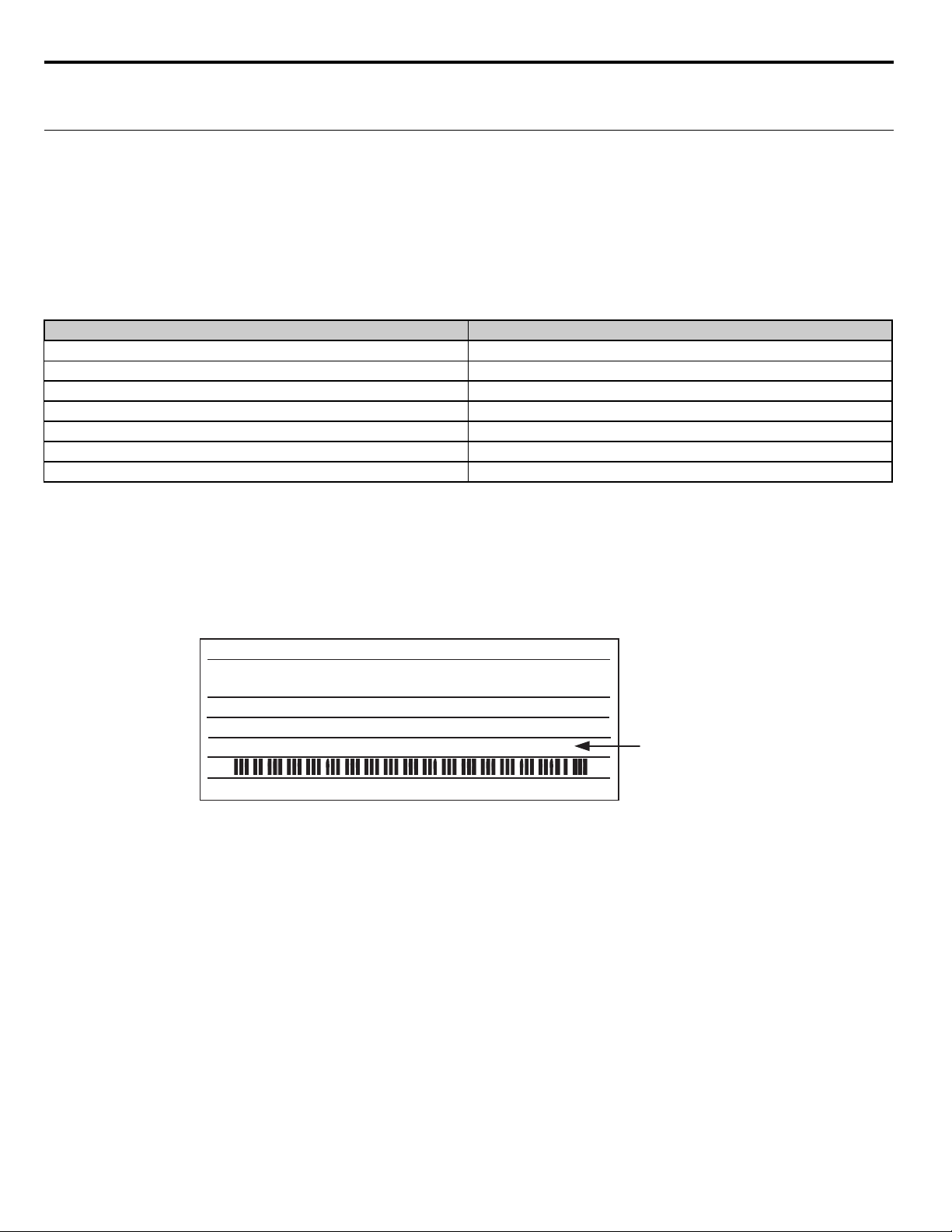
Figure 0.2
MODEL: CIMR-P7U2018 SPEC: 20181E
INPUT:
OUTPUT:
O/N:
S/N:
FILE NO: E131457 TYPE 1 ENCLOSURE
AC3PH 200-240V 50/60Hz HD:84A ND:89A
AC3PH 0-240V 0-400Hz HD:71A 27kVA ND:74.8A 29kVA
MASS: 11kg
1W9911234560123
PRG: 0034
IP20
DRIVE SOFTWARE
VERSION
Figure 1 Nameplate with PRG software number
The “PRG:” number on the drive nameplate reflects the software version. The software version normally increases to a higher number
with newer versions.
10 YASK AWA TM.iQp.07 iQpump Controller Programming Manual
Page 11

1
Programming
This chapter contains descriptions of all user accessible parameters contained in the drive.
Parameters are listed in alpha-numerical order. Parameter number and name, along with a detailed
description and its settings are described on the following pages.
iQpump BASIC PROGRAMMING PARAMETERS . . . . . . . . . . . . . . . . 12
MEMOBUS / MODBUS FUNCTION CODE DETAILS . . . . . . . . . . . . . 101
IQPUMP MEMOBUS / MODBUS STATUS REGISTERS . . . . . . . . . . . 111
PARAMETER LIST . . . . . . . . . . . . . . . . . . . . . . . . . . . . . . . . . . . . . . . . 260
MONITOR LIST . . . . . . . . . . . . . . . . . . . . . . . . . . . . . . . . . . . . . . . . . . . 291
FACTORY DEFAULT SETTINGS . . . . . . . . . . . . . . . . . . . . . . . . . . . . . 300
YASK AWA TM.iQp.07 iQpump Controller Programming Manual 11
Page 12

iQpump Drive Basic Programming Parameters
The initialization group contains parameters associated with initial drive setup. Parameters involving the display language, access levels,
initialization, and password are located in this group.
◆ A1 Initialization
■ A1-00 Language Selection
Setting Description
0 English (factory default)
2Deutsch
3 Francais
4Italiano
5 Espanol
6 Portugues
*Not returned to factory setting by initialization
■ A1-01 Access Level Selection
Setting Description
0Operation Only
2 Advanced Level (factory default)
If the iQpump drive is programmed for Operation Only (A1-01 = “0: Operation Only”), then only the OPERATION and the
PROGRAMMING menus are accessible. Within the PROGRAMMING menu only parameters A1-01 and A1-04 are adjustable.
If A1-01 is configured for Advanced Access (A1-01 = “2: Advanced Level”), then all menus and all parameters are shown. If the Access
Level Selection is set to Advanced, all parameters should be adjustable unless:
The iQpump drive parameters are password protected (A1-04) which will prevent access to A1-00 through A1-03 and all A2 parameters.
A digital input has been configured as a Program Lockout (H1-0x = 1B) is active.
During serial communication writing, if a parameter change is also attempted via the digital operator, a “BUSY - WRITE PROTECTED”
message will display. Parameter change will not be possible from the digital operator until an Enter command is received via the serial
communication to finish the serial writing process.
■ A1-03 Initialize Parameters
Setting Description
0 No Initialize (factory default)
1110 User Initialize
2220 2-Wire Initialize
3330 3-Wire Initialize
The iQpump drive can be set back to one of three default states via the A1-03 parameter.
1. User Initialization – 1110: The modified iQpump drive parameters are returned to the values selected as user settings. User settings are
stored when parameter o2-03 = “1: Set Defaults”.
2. 2-Wire Initialization – 2220: The iQpump drive parameters are returned to factory default values with digital inputs S1and S2
configured as Forward Run.
3. 3-Wire Initialization – 3330: The iQpump drive parameters are returned to factory default values with digital inputs S1, S2, and S5
configured as Run, Stop, and Forward / Reverse respectively.
After an initialization is performed, parameter A1-03 will automatically be set back to 0.
12 YASK AWA TM.iQp.07 iQpump Controller Programming Manual
Page 13

Figure 1.1
Note: 2-Wire Control is the most commonly used.
Stop switch
(NC contact)
Operation switch
(NO contact)
3-wire control
2-wire control
Run command
(run on momentary close)
Stop command
(stop on momentary close)
Sequence input common
S1
SN
S2
S1
SN
FWD Run/Stop
Figure 1. 2 and 3-Wire Control Wiring Examples
Important: Some parameters are unaffected by either the 2-Wire or 3-Wire initialization. The following parameters will not be reset
when parameter A1-03 = 2220 or 3330:
A1-00 Language Selection
E1-03 V/f Pattern Selection
o2-04 kVA Selection
■ A1-04 Password Entry
Setting Range: 0 ~ 9999
Factory Default: 0
If parameters A1-01 through A1-03 are locked (unchangeable), they can be unlocked by entering the correct password number into
A1-04.
Once the correct password number is entered and the specified parameters are unlocked, a 2-Wire or 3-Wire initialization will reset the
password to 0000.
Note: A1-04 will return to “0000” when the password has been entered.
■ A1-05 Select Password
Setting Range: 0 ~ 9999
Factory Default: 0
When the value set into A1-04 does NOT match the value set into A1-05, parameters A1-01 thru A1-03 cannot be changed. All other
parameters determined by A1-01 can be changed. Parameter A1-05 can be accessed by displaying parameter A1-04, then press and hold
the RESET key along with the MENU key simultaneously.
YASK AWA TM.iQp.07 iQpump Controller Programming Manual 13
Page 14
b1 Sequence
The Sequence Group contains parameters associated with starting and stopping the drive. Parameters involving the Run Command, Speed
Reference location, Stopping Method and Hand / Auto changeover are located in this group.
◆ b1-01 Reference (Auto Setpoint) Source Selection
Setting Description
0 Operator - Digital Preset Setpoint d1-01 (factory default)
1 Terminals - Analog Input Terminal A1 (or Terminal A2, see Parameter H3-13)
2 Serial Com - RS-485 Terminals R+, R-, S+ and S3 Option PCB - Option Board connected at 2CN
In order to run the iQpump drive and motor, the iQpump drive must receive a Run command and a Auto Setpoint command. Parameter
b1-01 specifies from where the Auto Setpoint is received when in the “Auto” mode. Switching into the “Auto” mode can be done by
pressing the AUTO button on the digital operator while the iQpump drive is stopped.
Important: If a Run command is input to the iQpump drive but no corresponding Auto Setpoint is input, the Run indicator on the digital
operator will turn on and the STOP indicator on the digital operator will blink.
To configure the iQpump drive to follow the “Hand Reference” set by the digital operator: Use the “Hand” mode by pressing the
hand key and set P5-01 = “1: Hand Reference (P5-02)”. The hand reference can then be entered into the P5-02 parameter.
The iQpump drive offers the ability to provide four types of “Auto Setpoint” reference sources. These Auto Setpoint reference sources are
determined by the setting of b1-01 and the drive set to “Auto” mode by pressing the Auto key on the digital operation.
Note: Prior to programming, it is recommended to first select the system units (P1-02) and the feedback device, Scaling
(P1-03). P1-03 will automatically scale the iQpump Setpoint.
Example:
P1-02 = 1: psi
P1-03 = 200, feedback range = 200 psi.
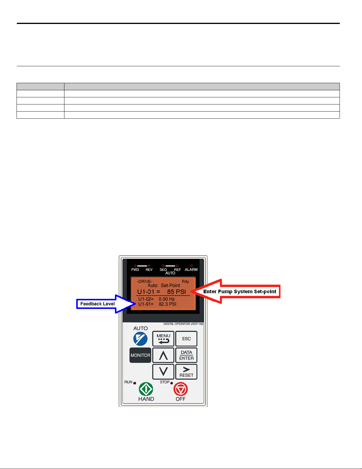
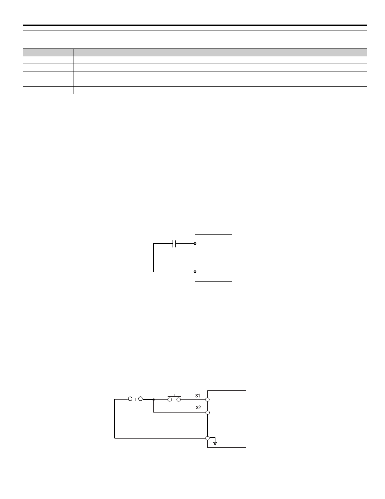
To configure the iQpump drive to follow an “Auto Setpoint” set by the digital operator: Set b1-01 = “0: Operator” (factory default),
The Auto Setpoint can then be entered into the U1-01 monitor parameter in the “-DRIVE-” menu.
Figure 1.2
Figure 2. Digital Operator Auto Setpoint
To configure the iQpump drive to follow an “Auto Setpoint” set by the analog input: Set b1-01 = “1: Terminals,” and connect a
potentiometer or external signal to the iQpump drive. Refer to Figu re 3. for connection diagram for the setpoint potentiometer.
14 YASK AWA TM.iQp.07 iQpump Controller Programming Manual
Page 15
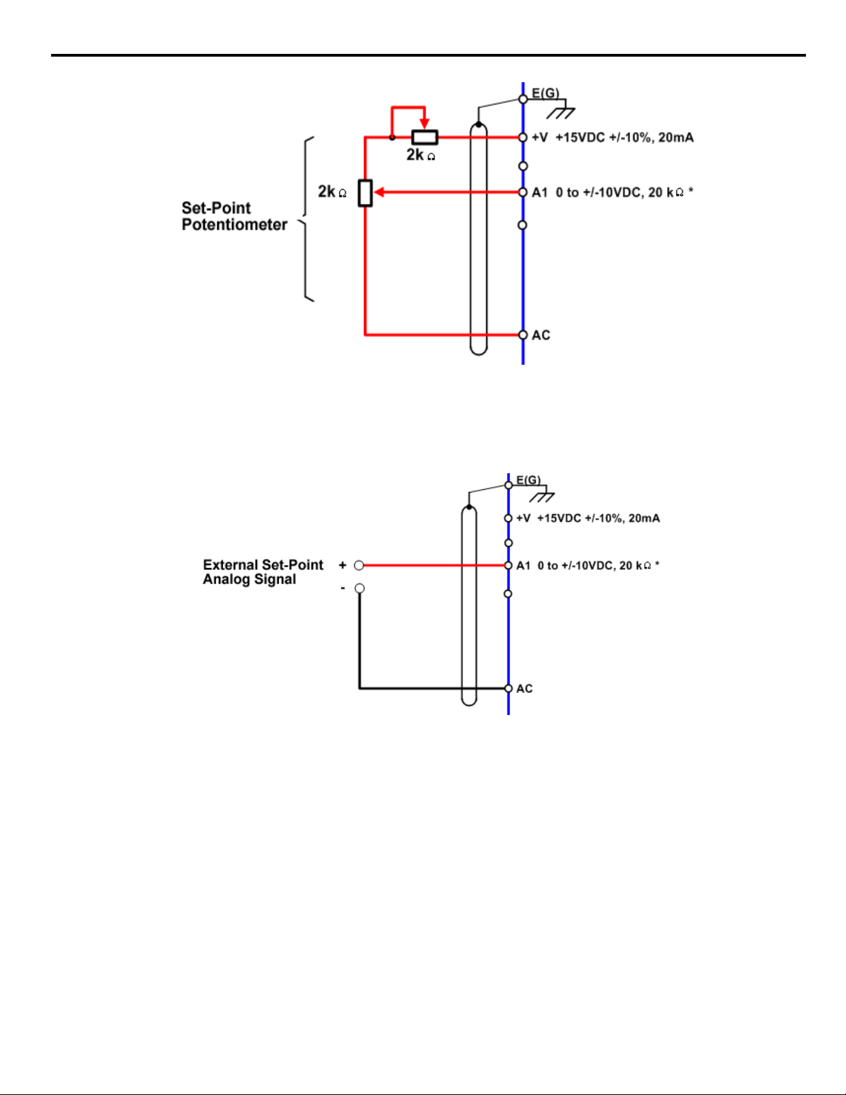
Figure 1.3
Figure 3. Setpoint Potentiometer Connection Diagram
Refer to Figure 4. for the connection diagram for an external analog signal setpoint reference.
Note: When b1-01 = 1 (terminals) and P5-01 = 0 (hand mode reference source), the setpoint and the hand reference are
determined by the external analog signal.
Figure 1.4
Figure 4. External Analog Signal Setpoint Reference
Setting the iQpump drive to receive the “Auto Setpoint” from serial communication: Set b1-01 = “2: Serial Com,” and connect the
RS-485 / 422 serial communications cable to terminals R+, R-, S+, and S- on the control I/O terminal block.
Refer to Figure 5. for the connection diagram using a PC to provide the auto setpoint reference to the iQpump drive. Further information
regarding communication protocols are referenced in Appendix A.
YASK AWA TM.iQp.07 iQpump Controller Programming Manual 15
Page 16
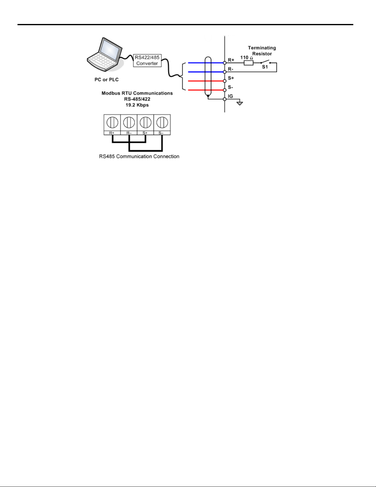
Figure 1.5
Figure 5. Connection Diagram of PC or PLC
To configure the iQpump drive to receive the “Auto Setpoint” for a network communication option card: Set b1-01= “3: Option
PCB,” and plug a network option board (p/n SI-J) into the 2CN port on the iQpump drive Control PCB. Consult the manual supplied with
the option board for instructions on integrating the iQpump drive into the network system.
The iQpump drive can support the following network communication options. Refer to the appropriate Installation Guide (IG) and
Technical Manual (TM) for further details. These network communications documents can be located at http://iQpump.yaskawa.com.
Profibus DP Option Card CM061 Manual: IG.AFD.12
DeviceNet Option Card CM05X Manual: IG.AFD.14
Modbus Plus Option Card CM071 Manual: IG.AFD.17
Modbus TCP/IP Option Card CM090 Manual: IG.AFD.25
EtherNet/IP Option Card CM092 Manual: IG.AFD.26
Important: If b1-01 = “3: Option PCB” but a network card is not installed in 2CN, an OPE05 Operator Programming Error will be
displayed on the digital operator and the iQpump drive will not run.
■ Start / Stop from Comm. Option Card (Parameter b1-01 = 3):
The iQpump Controller allows for the setpoint reference to be set via any of the following communication option cards:
Profibus DP Option Card CM061 Manual: IG.AFD.12
DeviceNet Option Card CM05X Manual: IG.AFD.14
Modbus Plus Option Card CM071 Manual: IG.AFD.17
Modbus TCP / IP Option Card CM090 Manual: IG.AFD.25
EtherNet / IP Option Card CM092 Manual: IG.AFD.26
16 YASK AWA TM.iQp.07 iQpump Controller Programming Manual
Page 17
◆ b1-02 Run Command Selection
S1
S2
SN
FWD Run/Stop
REV Run/Stop
3-wire control
Stop switch
(NC contact)
Operation switch
(NO contact)
Run command
(run on momentary close)
Stop command
(stop on momentary open)
Sequence input common
SN
Setting Description
0 Operator (factory default)
1 Terminals
2Serial Com
3 Option PCB
5Timed Run
b1-02 = 0, Operator (factory default).
The iQpump drive comes factory programmed for Start and Stop from the Keypad.
The iQpump drive can be programmed to receiver a Run command from four different inputs: digital operator, terminals, serial
communications, or an option PCB.
If the Run command input is determined by the digital operator: Set b1-02 = “0: Operator,” and the HAND and OFF keys will be
used to provide the Run command to the iQpump drive.
b1-02 = 1, Terminals
If the Run command input is determined by the external terminals: Set b1-02 = “1: Terminals” and initiate an external Run
command by a contact closure between terminals S1 and SN. Refer to Figure 8. for the connection diagram of the external Run
command.
Note: To use the external terminals requires the iQpump drive to be set to “Auto” mode by pressing the Auto key.
Select between 2-wire and 3-wire control operation by doing the following:
2-Wire Control The factory default setting is for 2-wire operation. In the 2-wire configuration a closure between S1 and SN will be
interpreted as a Forward Run command by the drive.
Figure 1.6
Figure 6. 2-Wire Control
3-Wire Control When any of the multi-function digital input parameters, H1-01 through H1-05, is set to 0, terminals S1 and S2 become
Run and Stop, respectively. The multi-function digital input that was set to 0 will function as a Forward / Reverse input for the iQpump
drive. When the Forward / Reverse input is open the iQpump drive will run in the Forward direction and when the input is closed, the
iQpump drive will run in the Reverse direction.
In 3-wire operation a momentary closure (> 50mS) of S1 will cause the iQpump drive to run provided that S2 is held closed. The iQpump
drive will stop anytime the S2-SN connection is broken. If the 3-wire configuration is implemented via a 3-wire Initialization (A1-03 =
“3330: 3-Wire Initial”), then terminal S3 becomes the Forward / Reverse input.
Note: Reverse operation is disabled in the iQpump drive; however, in 3-wire control, one of the multi-function digital inputs
needs to be programmed to 0. Otherwise, the 3-wire control will not work.
Figure 1.7
YASK AWA TM.iQp.07 iQpump Controller Programming Manual 17
Figure 7. 3-Wire Control
Page 18
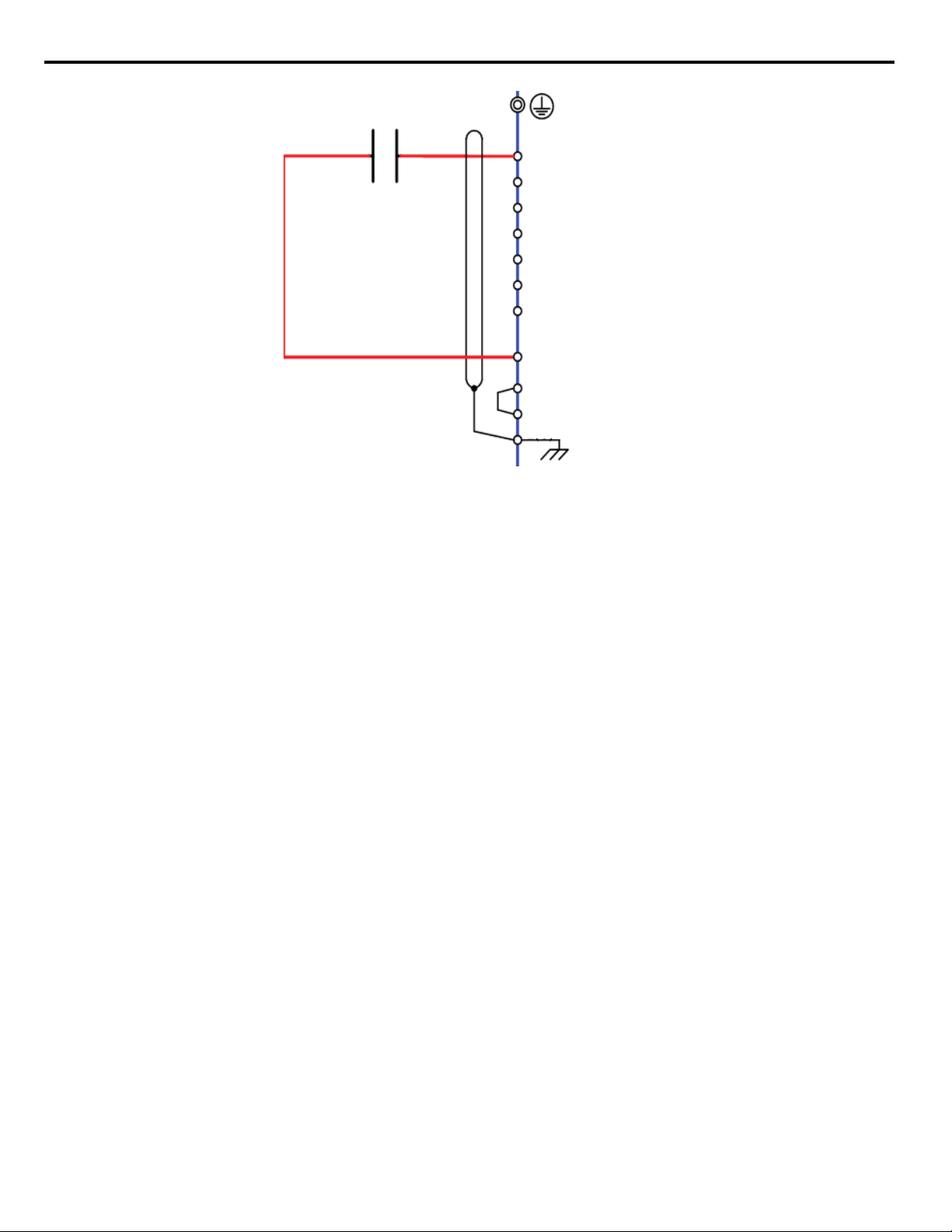
Figure 1.8
b
b1-02 = 1
Auto Mode Start
External Switch or
Relay Contact
S1
S2
S3 (H1-01)
S4 (H1-02)
S5 (H1-03)
S6 (H1-04)
S7 (H1-05)
SN
SC
SP 24 VDC +/- 20%, 8 mA
E (G)
b1-02 = 2, Serial Com
Figure 8. Connection Diagram of External Start / Stop Switch
If the Run command is determined by Serial Communication:“b1-02 = 2: Serial Communications,” and initiate the Run command
through the serial communications. Refer to Figure 8. (in the previous b1 sequence section) for the connection diagram for serial
communications through the RS232 / 485 terminals to R+, R-, S+ and S-. The following is a simple setup procedure for programming the
iQpump drive and PC Serial communications to initiate Run and Stop commands through serial communications.
1. Program b1-02 = “2: Serial communications”.
2. Program the following H5 parameters:
H5-01 Serial Communication Address: 31
H5-02 Serial Baud Rate: 9600 Baud (setting 3).
H5-03: Serial Communication Parity Selection: None (setting 0)
3. Initiate a Start / Stop command
iQpump command register number: 0001
Stop Command: Transmit value of 0000 (16 bit) to iQpump command address.
Start Command: Transmit value of 0001 (16 bit) to iQpump command address.
Reset Command: Transmit value of 0008 (16 bit) to iQpump command address.
b1-02 = 3, Option PCB
If the Run command input is determined by a network communications option PCB: “b1-02 = 3: Option PCB,” and initiate the Run
command through the available network communications option PCB listed below. The Installation Guides (IG) and Technical Manuals
(TM) are available at http://iQpump.yaskawa.com.
The iQpump Controller allows for monitoring, diagnostics and control using any of the following communication option cards:
Profibus DP Option Card CM061 Manual: IG.AFD.12
DeviceNet Option Card CM05X Manual: IG.AFD.14
b1-02 = 5, Timed Run
If the Run command input is determined by a Timed Run: “b1-02 = 5: Timed Run,” when this feature is enabled, the drive will run at
the HAND frequency reference for the time specified in parameter P4-18. Timed Run cannot be enabled when in multiplex mode
(P1-01 > 0).
Modbus Plus Option Card CM071 Manual: IG.AFD.17
Modbus TCP / IP Option Card CM090 Manual: IG.AFD.25
EtherNet / IP Option Card CM092 Manual: IG.AFD.26
Note: Refer to the communication card instruction manual or consult factory for installation and operation instructions.
18 YASK AWA TM.iQp.07 iQpump Controller Programming Manual
Page 19
Run / Stop Control:
“Hand”
Key
“Off”
Key
P4-18
R-S Run Time
P4-19
R-S Stop Time
P4-18
R-S R un Time
P4-19
R-S Stop Time
P4-18
R-S Run Time
P4-19
R-S Stop Time
P4-18
R-S Run Time
P4-19
R-S Stop Time
P4-18
R-S Run T ime
Cycle
1
Cycle
2
Cycle
3
Cycle
4
Cycle
5
P4-18
R-S Run T ime
Cycle
1
(Cy cle 0)
Output
Frequency
P5-02
Sleep
Mess age
Run /Stop
Finished
Mess age
R-S Cycle Count
P4-20 = 5
• Only enabled when all three Run / Stop Control parameters are set to a value greater than zero (P4-18 > 0, P4-19 > 0, and P4-20 > 0).
• Available only when in HAND or LOCAL mode.
• PI control is disabled.
• Will always start off running when a run command is given.
• A stop command, power loss or fault will reset all timers and counters associated with the Run / Stop Control.
• A stop command will result in a stopping method set by parameter b1-03.
• When the “Run” portion of the timer expires, the drive stop using the stopping method set by parameter b1-03.
• When stopped due to the “Run” timer expired, the standard “sleep” message will be displayed on the operator.
• When stopped because the final cycle count has been exceeded, the digital operator will display “Run / Stop Finished”. The display
will be cleared when a stop command is given or power is lost.
• If a fault (not auto-restart) occurs during Run / Stop Control, all timers and counters are reset.
• If an auto-restart is in process, under most circumstances the Run / Stop Control will continue to operate. However, if the stop timer
expires prior to the auto-restart expiring, the drive will wait until the auto-restart time expires before resuming normal Run / Stop
Control.
When this feature is enabled and the drive is given a run command, the drive will run for the time specified in parameter P4-18, then stop
for the time specified in parameter P4-19. It will do this the number of times programmed in parameter P4-20. (Refer to parameters P418, P4-19 and P4-20.) The display will show one of two messages if the drive is stopped due to this feature. Run-Stop control cannot be
enabled when a multiplex mode (P1-01 > 0).
Timed Run:
If parameter b1-02 is set to 5 “Timed Run”, the timed run feature will be enabled. When “Timed Run” is enabled, Terminal S1 will be a
normally open “start” input and Terminal S2 will be a normally closed “stop” input. The drive can be started by either causing a rising
edge (open to close) on the S1 digital input when S2 is closed, or both S1 and S2 are closed when power is applied to the drive. The drive
will then start running at the HAND frequency reference P5-02 and run for the time specified in parameter P4-18. If the drive needs to be
stopped before the P4-18 timer expires, the circuit connected to Terminal S2 can be opened, or the Stop or Off keys on the digital operator
can stop the drive. The drive can be re-started by simply causing another rising edge on Terminal S1. There will be no modified display or
messages when the drive is stopped due to the Timed Run feature. If the drive is switched into HAND or LOCAL mode, the timed run
feature will be disabled.
1. Wire-Break detection for Terminal A2 will be completely disabled during Timed Run control.
2. The pre-charge feature is disabled during Timed Run control.
3. Uses the “Hand” reference as the frequency reference. If P5-01 is set to 1, parameter P5-02 will be used as the reference. If P5-02 is set
to 0, Terminal A1 will be used as the reference.
4. The “Not Maintaining Setpoint”, and “Low Feedback” faults are disabled during Timed Run control.
5. The “Loss of Prime” fault (if enabled) will become active when the output frequency comes to within 1 Hz of the frequency reference.
6. The Timed Run Control will take priority over the “Auto Mode Fixed Speed” mode (digital input).
When this feature is enabled, the drive will run at the “Hand” frequency reference for the time specified in parameter P4-18. Timed Run
cannot be enabled when in Multiplex Mode (P1-01 > 0). (Refer to parameter P4-18.)
Figure 1.9
Figure 9. Run / Stop Control - HOA Operator JVOP162 - Coast to Stop
YASK AWA TM.iQp.07 iQpump Controller Programming Manual 19
Page 20
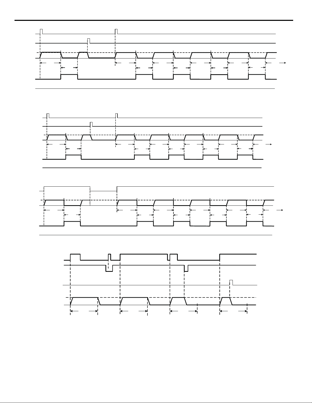
Figure 1.10
Key
“Off”
Key
P4- 18
R-S R un Time
R-S Stop Time
P4-18
R-S Run Time
P4-19
R-S Stop Time
P4-18
R-S Run Time
P4-19
R-S Stop Time
P4-18
R-S Run Time
P4-19
R-S Stop Time
P4-18
R-S Run Time
Cycle
1
Cycle
2
Cycle
3
Cycle
4
Output
Frequency
P5-02
Sleep
Message
Run/Stop
Finished
Message
P4-19
Cycle
1
(Cy cle 0)
P4-19
R-S Stop Time
P4-18
R-S Run Time
R-S C yc le Count
P4- 20 = 5
“Hand”
“Run”
Key
“Stop”
Key
P4-1 8
R-S R un Time
R-S Stop Time
P4-18
R-S Run Time
P4-19
R-S Stop Time
P4-18
R-S R un Time
P4-19
R-S Stop Time
P4-18
R-S R un Time
P4-19
R-S Stop Time
P4-18
R-S Run Time
Cycle
1
Cycle
2
Cycle
3
Cycle
4
Output
Frequency
P5-02
Sleep
Message
Run/Stop
Finished
Message
P4-19
Cycle
1
(Cycle 0)
P4-19
R-S Stop Time
P4-18
R-S Run Time
R-S Cycle Count
P4-2 0 = 5
NOTE: I f the JVOP-160 is installed, t he drive must already be i n
“Local” mode for t he Run /Stop feature to operat e .
Figure 1.11
Figure 10. Run / Stop - HOA Operator JVOP162 - Ramp to Stop
Figure 1.12
Figure 1.13
“Hand” DI
(H1- 0x = 80)
Output
Frequency
Sleep
Mess age
Run /Stop
Finished
Mess age
P4-18
R-S Run Time
Terminal
S1
Terminal
S2
“Off ” or
“Stop”
Key
Output
Frequency
Cycle
1
R-S Stop Time
Figure 11. Run / Stop - HOA Operator JVOP160 - Ramp to Stop
P4-18
R-S R un Time
Cycle
P5- 02
P4- 19
(Cycle 0)
P4-18
R-S R un Time
Cycle
1
P4-19
R-S Stop Time
R-S C ycl e Count
P4-20 = 5
P4-18
R-S R un Time
Cycle
2
R-S S top Time
P4-19
Figure 12. Run / Stop - HOA Operator JVOP160 - Coast to Stop
P5-02
P4-18
R-S Run Time
P4-18
R-S Run Time
P4-18
R-S Run Time
Figure 13. Timed Run Operation (b1-02 = 5)
3
P4- 19
R-S S top Time
P4-18
R-S R un Time
P4-18
R-S Run Time
Cycle
4
R-S Stop Time
P4-19
P4-18
R-S R un Time
20 YASK AWA TM.iQp.07 iQpump Controller Programming Manual
Page 21
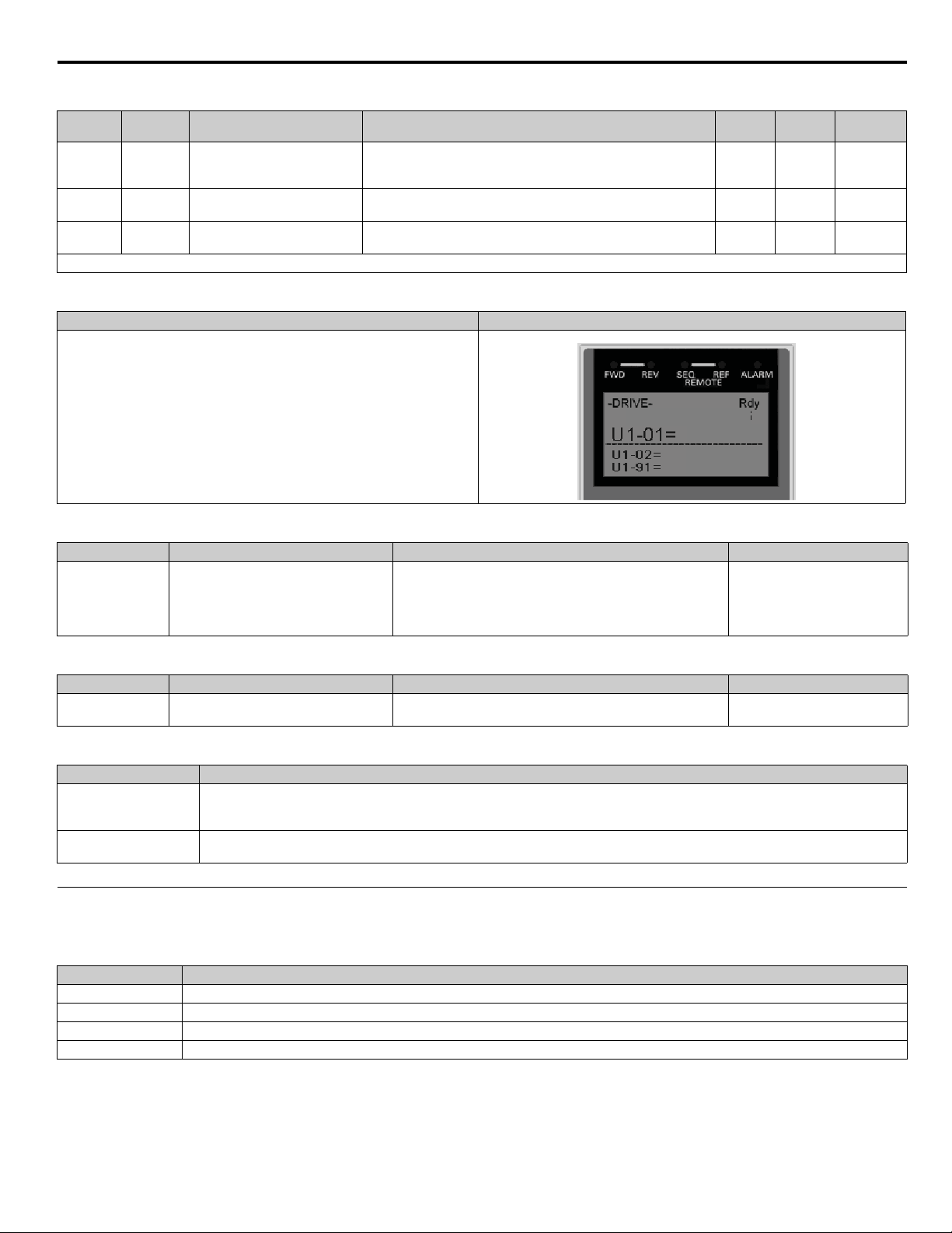
Table 1 Related Parameters <0034>
Run/Stop Control
40.00Hz
0.00 Hz
0.0 PSI
Parameter
No.
P4-18
P4-19
P4-20
Denotes that parameter can be changed when the drive is running.
Addr. Hex
831
832
833
Parameter Name
Digital Operator Display
Run / Stop Control Run Time
R-S Run Time
Run / Stop Control Stop Time
R-S Stop Time
Run / Stop Control Cycles
R-S Cycle Count
Description
This parameter sets the amount of time the drive will run for when
the Run / Stop Control is enabled. It will also set the “timed” run time
when enabled (b1-02 = 5).
This parameter sets the amount of time the drive will stop for when
the Run / Stop Control is enabled.
This parameter determines how many Run / Stop Cycles the drive
will execute before staying stopped.
Setting
Range
0.0 ~
6000.0 min
0.0 ~
6000.0 min
0 ~ 1000 0 Programming
Factory
Setting
0.0 min Programming
0.0 min Programming
Table 2 Digital Operator Display
Description Operator Display
When the Run / Stop function is enabled, the display will change as shown.
The Run / Stop function is enabled by setting parameters P4-18, P4-19 and P4-20
to values greater than zero.
Table 3 Fault <0034>
Fault Display Description Cause Countermeasures
Run / Stop Control has been enabled when in multiplex mode.
oPE15
Run / Stp-
Run / Stop or Timed Run enabled in
multiplex mode.
(P1-01 > 0, P4-18 > 0, P4-19 > 0 and P4-20 > 0).
OR
Timed Run Control has been enabled when in multiplex mode.
(P1-01 > 0 and b1-02 = 5).
Reprogram P1-01, P4-18 ~ P4-20,
or b1-02.
Menu
Location
Table 4 Message <0034>
Fault Display Description Cause Countermeasures
Run / Stop Finished Run / Stop Cycles have completed.
The number of Run / Stop Cycles since the last HAND command
has completed.
Press “Off” to clear the message.
Table 5 Multi-Function Output Setting <0034>
Setting Description
51
52
Run / Sto p - Stop
Closed: Drive is stopped due to the Run / Stop control (P4-18 and P4-19) OR
Closed: Drive is stopped because the Run / Stop cycles have completed (P4-20).
Run / Stop - Finish
Closed: Drive is stopped because the Run / Stop cycles have completed (P4-20).
◆ b1-03 Stopping Method
There are four methods of stopping the iQpump drive when the Run command is removed.
Setting Description
0 Ramp to Stop (factory default)
1Coast to Stop
2 DC Injection to Stop
3 Coast w / Timer
YASK AWA TM.iQp.07 iQpump Controller Programming Manual 21
Page 22
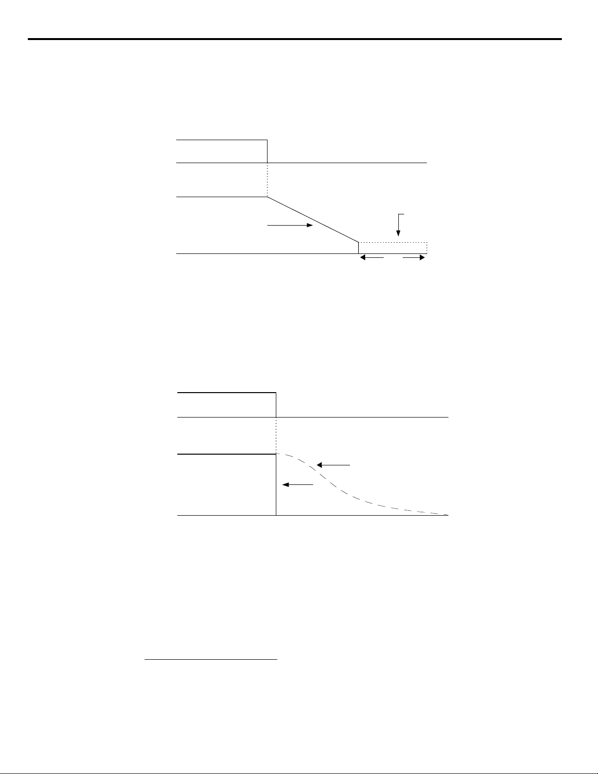
0: Ramp to stop: When the Run command is removed, the iQpump drive will decelerate the motor to 0 rpm. The rate of deceleration is
ON
OFF
Run Command
Output Frequency
Deceleration Time (C1-02)
DC Injection Brake
100 %
0 %
TIME
| b2-04 |
b2-01
(CLOSED)
(OPEN)
Time to Stop
Output Freq. at time of stop command
Maximum Frequency (E1-04)
------------------------------------------------------------------------------------------- Se tt in g o f ac ti v e D e c el Ti m e ( C 1 -0 2 or C1-04)×=
ON
OFF
Run Command
Output Frequency
Drive Output Frequency Interrupted
100 %
0 %
TIME
Motor Speed
(CLOSED)
(OPEN)
04)-(E1Frequency Maximum
FrequencyOutput 1004)-(b2
Time BrakeInjection DC
××
=
determined by the active deceleration time. The factory default Decel Time is in parameter C1-02.
When the output frequency has dropped below the DC Injection Start Frequency in b2-01 (Default = 0.5 Hz) DC current will be injected
in the motor at a level determined by b2-02 (50% Default). The DC Injection condition will occur for the time specified by b2-04 (0.0
Default), to establish the end point of the ramp. DC injection can be used to insure the motor is at zero rpm prior to the iQpump drive
shutting off.
Figure 1.14
Figure 14. Deceleration to Stop
The actual deceleration time can be determined by the following formula.
If S-Curve characteristics are specified by the iQpump drive programming, they will add to the total time to stop.
1: Coast to stop: When the Run command is removed, the iQpump drive will turn off its output and the motor will coast (uncontrolled
deceleration). The friction of the driven equipment will eventually overcome any residual inertia of the system and the rotation will stop.
Figure 1.15
Figure 15. Coast to Stop
Important: After a stop is initiated, a subsequent Run commands input before the Minimum Baseblock Time (L2-03) has expired, will
be ignored.
2: DCInj to Stop: When the Run command is removed, the iQpump drive will Baseblock (turn off its output) for the Minimum
Baseblock Time (L2-03). Once the Minimum Baseblock Time has expired, the iQpump drive will inject DC current into the motor
windings to lock the motor shaft. The stopping time will be reduced as compared to Coast to Stop. The level of DC Injection current is set
by parameter b2-02 (50% Default). The DC Injection brake time is determined by the set value in b2-04 and the output frequency at the
time the Run command is removed.
22 YASK AWA TM.iQp.07 iQpump Controller Programming Manual
Page 23

Figure 1.16
ON
OFF
Run Command
Output Frequency
Drive Output Voltage Interrupted
DC Injection Brake
DC Injection Brake Time
Minimum Baseblock
Time (L2-03)
100 %
0 %
DC Injection Brake Time
b2-04 x 10
b2-04
10%
100% (Maxim um
Output Frequency)
b2-04
(CLOSED)
(OPEN)
Run Command
Output Frequency
Drive Output
Voltage
Interrupted
OFF
ON
Timer Value T
(C1-02)
100 %
0 %
Operat ion Wait Time ( T)
Deceleration
Time (C1-02 )
Minimu m
Baseblock
Time (L2-03)
Minimu m
Output
Frequency
100% (Maximum
Output
Frequency)
Output Fr equency at S top Command Input
Ignored
Run Command
Timer Value T
(OPEN)
(CLOSED)
Figure 16. DC Injection Braking to Stop
Important: If an overcurrent (OC) fault occurs during DCInj to Stop, lengthen the Minimum Baseblock Time (L2-03) until the fault no
longer occurs.
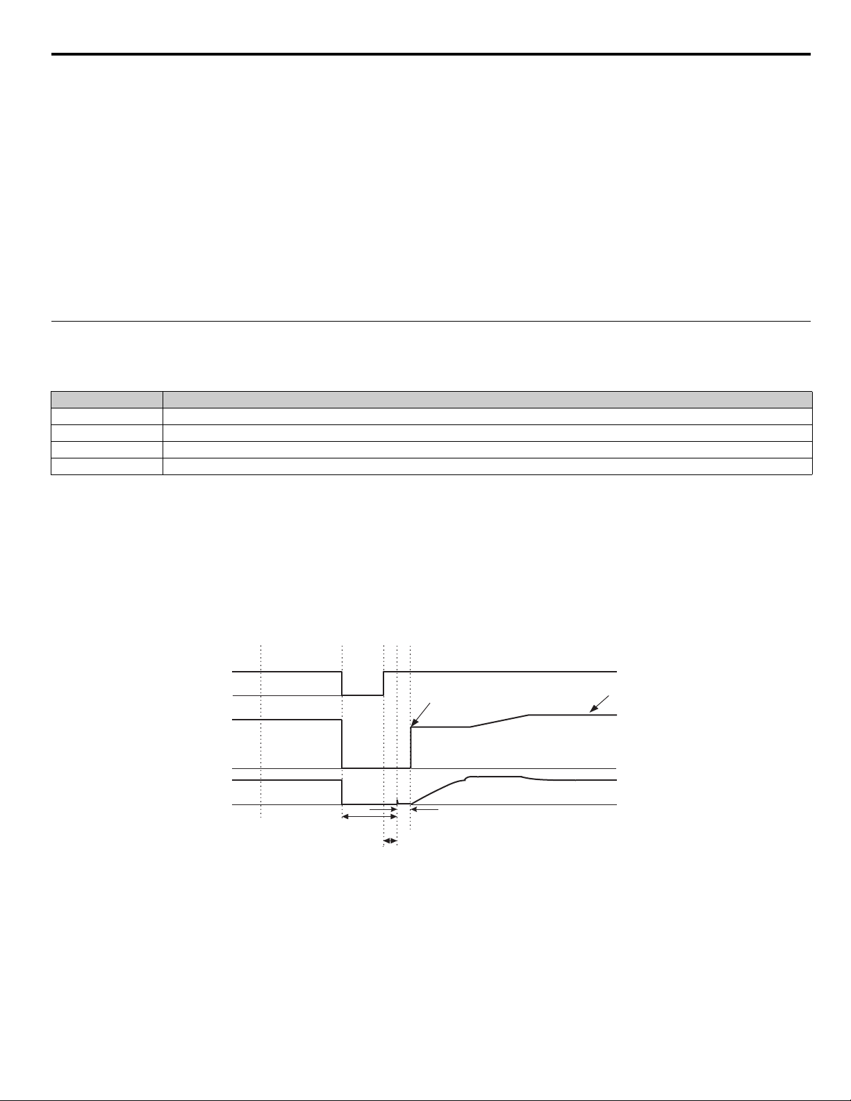
3: Coast w / Timer: When the Run command is removed, the iQpump drive will turn off its output and the motor will coast to a stop. If
a Run command is input before time T (operation wait time) expires, the iQpump drive will not run and the Run command will need to be
cycled before operation can occur. The time T (operation wait time) is determined by the output frequency when the Run command is
removed and the active deceleration time (C1-02).
Figure 1.17
◆ b1-07 Local / Remote Run Selection
◆ b1-08 Run Command Selection During Programming
As a safety precaution, the iQpump drive will not normally respond to a Run input when the digital operator is being used to adjust
parameters. If it is necessary that external Run commands be recognized even while the drive is being programmed, set b1-08 = “1:
Enabled.”
YASK AWA TM.iQp.07 iQpump Controller Programming Manual 23
Figure 17. Coast to Stop with Timer
Setting Description
0
Cycle External Run - If the run command is closed when switching from Hand (local) mode to Auto (remote) mode, the drive will not run.
(factory default)
1 Accept External Run - If the run command is closed when switching from Hand (local) mode to Auto (remote) mode, the drive WILL run.
Note: Used with LCD Operator only.
Setting Description
0 Disabled (factory default)
1 Enabled
Page 24

◆ b1-11 Drive Delay Time Setting
DDLY
Waiting to RUN
Setting Range: 0 ~ 600 s
Factory Default: 0 s
If a time is set into parameter b1-11, the iQpump drive will delay executing any run command until the b1-11 time has expired. During
iQpump drive delay time execution, the digital operator will display:
Both the ALARM and Run indicators will blink while the iQpump drive waits to execute the Run command.
24 YASK AWA TM.iQp.07 iQpump Controller Programming Manual
Page 25

b2 DC Braking
Output Frequency
t
b2-01
||
b2-04
ime
The DC Braking Group contains parameters associated with the DC injection braking feature. Parameters involving the starting
frequency, current level, braking time, and motor pre heat current level are located here.
◆ b2-01 DC Injection Braking Start Frequency
Setting Range: 0.0 ~ 10.0 Hz
Factory Default: 0.5 Hz
Parameter b2-01 sets the output frequency where the iQpump drive begins DC Injection during Ramp to stop in order to lock the rotor
of the motor and established the end point of the ramp. If b2-01 < E1-09 (Minimum Frequency), then DC Injection begins at E1-09.
Parameter b2-01 also determines the output frequency that the iQpump drive must be at or below before a Zero Speed condition is
considered true. This affects any digital output configured as a Zero Speed signal (H2-0x = “1: Zero Speed”).
Figure 1.18
DC injection
Figure 18. DC Injection Braking During Stopping
◆ b2-02 DC Injection Braking Current
Setting Range: 0 ~ 100%
Factory Default: 50%
The level of DC Injection Braking Current affects the strength of the magnetic field attempting to lock the motor shaft. Increasing the
level of current will increase the amount of heat generated by the motor windings and should only be increased to the level necessary to
hold the motor shaft. DC Injection current is set in percentage of the iQpump drive rated output current. iQpump drive rated output
current is stated on the iQpump drive nameplate.
◆ b2-03 and b2-04 DC Injection Braking Time
Parameter No. Parameter Name
b2-03 DC Injection Braking Time at Start
b2-04 DC Injection Braking Time at Stop
Setting Range: 0.00 ~ 10.00 s
Factory Defaults: b2-03 = 0.00 s and b2-04 = 0.50 s
The iQpump drive can be programmed to automatically DC Inject for a predetermined amount of time prior to accelerating to speed (b2-
03) and / or at the end of a Ramp to stop (b2-04). Parameter b2-03 can be used to stop a rotating motor prior to attempting acceleration
(i.e. a wind milling fan). If DC Injection braking at start or Speed Search is not enabled, attempting to drive a spinning motor may cause
nuisance tripping.
Parameter b2-04 can be used to resist any residual motion of the load after the deceleration has finished.
YASK AWA TM.iQp.07 iQpump Controller Programming Manual 25
Page 26

Figure 1.19
Output Frequency
DC injection
b2-03 b2-04
Figure 19. DC Injection Braking During Starting and Stopping
Parameter b2-04 also serves the function of affecting the length of time DC Injection to stop (b1-03 = “2: DC Injection to Stop”) will
occur.
◆ b2-09 Motor Pre-Heat Current
Setting Range: 0 ~ 100%
Factory Default: 0%
A DC current can be circulated within the motor windings while the motor is stopped. The current will produce heat within the motor and
prevent condensation. Parameter b2-09 determines the percentage of the iQpump drive rated output current that will be used for the motor
pre-heat function. This function can be useful in applications where the motor sits for extended periods of time in humid conditions.
Motor pre-heating can only be initiated by closing a digital input programmed as a Motor Pre-heat Input (H1-0x = 60). Check with the
motor manufacturer to determine the maximum acceptable current level the motor can withstand when stopped. Be sure not to exceed the
motor manufacturers recommended level.
26 YASK AWA TM.iQp.07 iQpump Controller Programming Manual
Page 27
b3 Speed Search
The Speed Search function allows the iQpump drive to determine the speed of a motor shaft that is being driven by rotational inertia.
Speed Search will allow the iQpump drive to determine the speed of the already rotating motor and begin to ramp the motor to a set speed
without first having to bring it to a complete stop. When a momentary loss of supply power is experienced, the iQpump drive output is
turned off. This results in a coasting motor. When power returns, the iQpump drive can determine the speed of the coasting motor and
start without requiring it to be brought to minimum speed. Speed Search can be programmed to always be active by setting b3-01 or it can
be commanded by remote contact closure by setting a digital input.
There are two forms of Speed Search in the drive, the speed estimation method and the current detection method.
Important: When setting the iQpump drive for remote Speed Search input, via a contact closure, the method of Speed Search is
determined by the setting of b3-01. If b3-01 = “0: SpdsrchF Disable” then the remote input will initiate speed estimation method, and if
b3-01 = “2: SpdsrchI Disable,” then the remote input will start the current detection method.
Parameters L2-03 and L2-04 also affect the current detection method of Speed Search operation.
◆ b3-01 Speed Search Selection
This parameter is effective only when the iQpump drive is given a new Run command.
Setting Description
0 SpdsrchF Disable
1SpdsrchF Enable
2 SpdsrchI Disable (factory default)
3SpdsrchI Enable
Speed Estimation: Method (b3-01 = 0 or 1) The speed estimation method will calculate the speed using measurements of residual
motor fields. The speed estimation version is bi-directional and will determine both the motor speed and direction. To enable speed
estimation Speed Search at start, set b3-01 = “1: SpdsrchF Enable”.
Important: If the speed estimation method of Speed Search is to be used, then Auto-tuning must be performed prior to using Speed
Search. If the length of cable between the iQpump drive and motor is ever changed after Auto-tuning then Auto-tuning should be
performed again
Important: The speed estimation mode cannot be used when there are multiple motors operated by one iQpump drive or the motor is two
or more frames smaller than the standard size motor per the iQpump drive capacity.
Figure 1.20
AC power supply
Output frequency
Output current
Minimum baseblock time (L2-03) x 0.75 *1
Minimum baseblock time (L2-03) x 0.75*1
OFFON
*2
Start using
speed detected
10 ms
*1 Baseblock time may be reduced by the output frequency
immediately before the baseblock.
*2
After AC power supply recovery, the drive waits for the
minimum Speed Search Wait Time (b3-05).
Set frequency
reference
Figure 20. Speed Search (Estimated Speed Method) after momentary power loss
where the power loss time is less than the minimum baseblock time
YASK AWA TM.iQp.07 iQpump Controller Programming Manual 27
Page 28
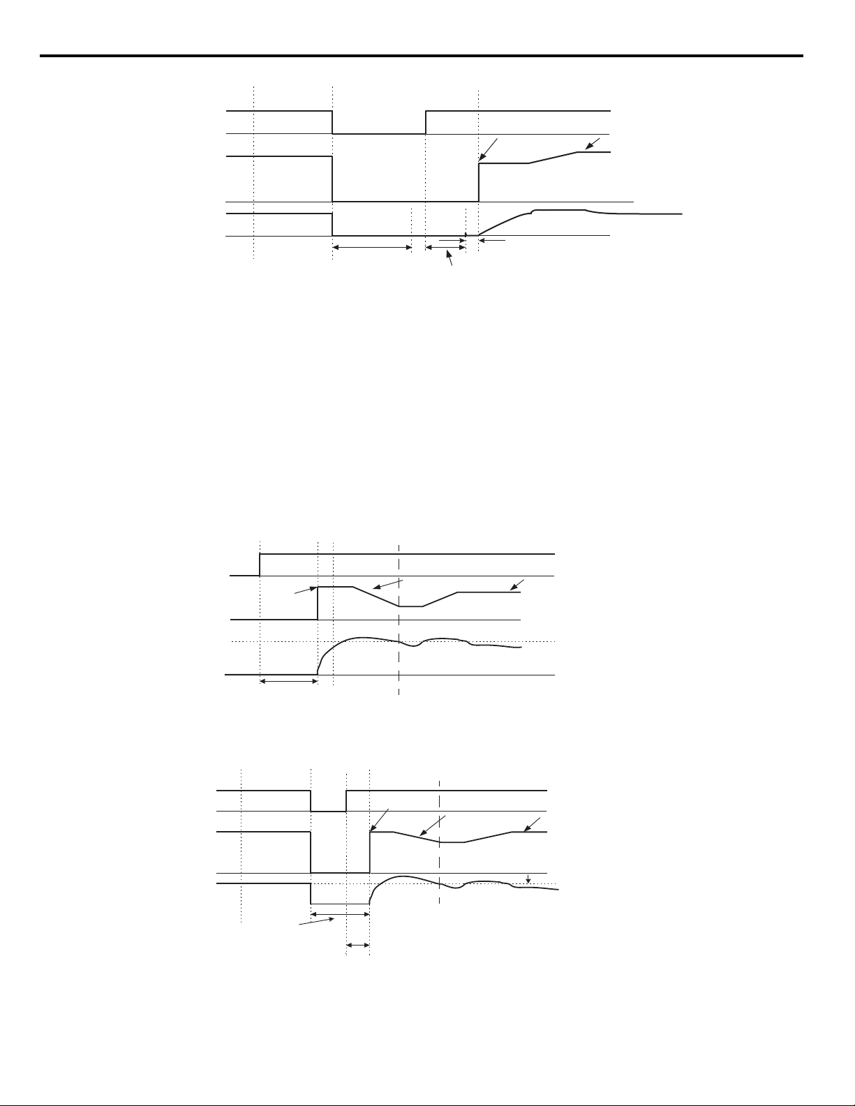
Figure 1.21
AC power supply
Output frequency
Output current
OFFON
Start using speed detected
Set frequency
reference
Minimum baseblock time
(L2-03)
10 ms
Speed Search Wait Time
(b3-05)
Note: If the frequency immediately before the baseblock is low or the power supply break time is long,
operation may be the same as the search in case 1.
Note: If the frequency immediately before the baseblock is low or the power supply off time is long,
operation may be the same as the search in case 1.
Run command
Output frequency
Output current
OFF ON
b3-02
Deceleration time set in b3-03
Set frequency
reference
Minimum baseblock time
(L2-03)
Maximum output
frequency or
set frequency
* Lower limit is set using Speed Search Time (b3-05).
*
Search Delay Time (b3-05).
Speed search current level
AC power supply
Output frequency
Output current
OFFON
Output frequency before power loss
Set frequency
reference
Minimum baseblock time (L2-03)
*1 Baseblock time may be reduced by the output frequency
immediately before baseblock.
*2 After AC power supply recovery, drive waits for the minimum
Speed Search Wait Time (b2-03).
Deceleration
time set in b3-03
b3-02
speed search operating current
*2
*1
b3-05
Figure 21. Speed Search (Estimated Speed Method) after momentary power loss
where the power loss time exceeds the minimum baseblock time
Current Detection Method (b3-01 = 2 or 3): The current detection method starts searching from a predetermined frequency while
monitoring the iQpump drive output current to determine when the rotor speed and the iQpump drive output speed (frequency) match.
The current detection version is not bi-directional. To enable current detection Speed Search at start set b3-01 = “3: SpdscrhI enable” and
program any digital input equal to Speed Search 1 (H1-0x = 61) or Speed Search 2 (H1-0x = 62). Speed Search 1 will start searching from
the max. frequency (E1-04) and ramp down to meet the rotor speed. Speed Search 2 will start searching from the set frequency and ramp
down to meet the rotor speed.
Important: If a UV1 fault occurs when current detection Speed Search is attempted, increase the setting of L2-04.
Important: If an OC fault occurs when Speed Search is attempted after power loss recovery, increase the setting of L2-03.
Figure 1.22
Figure 22. Speed Search (Current Detection Method) at Startup
Figure 1.23
28 YASK AWA TM.iQp.07 iQpump Controller Programming Manual
Figure 23. Speed Search (Current Detection Method) after momentary power loss
where the power loss time is less than the minimum baseblock time
Page 29
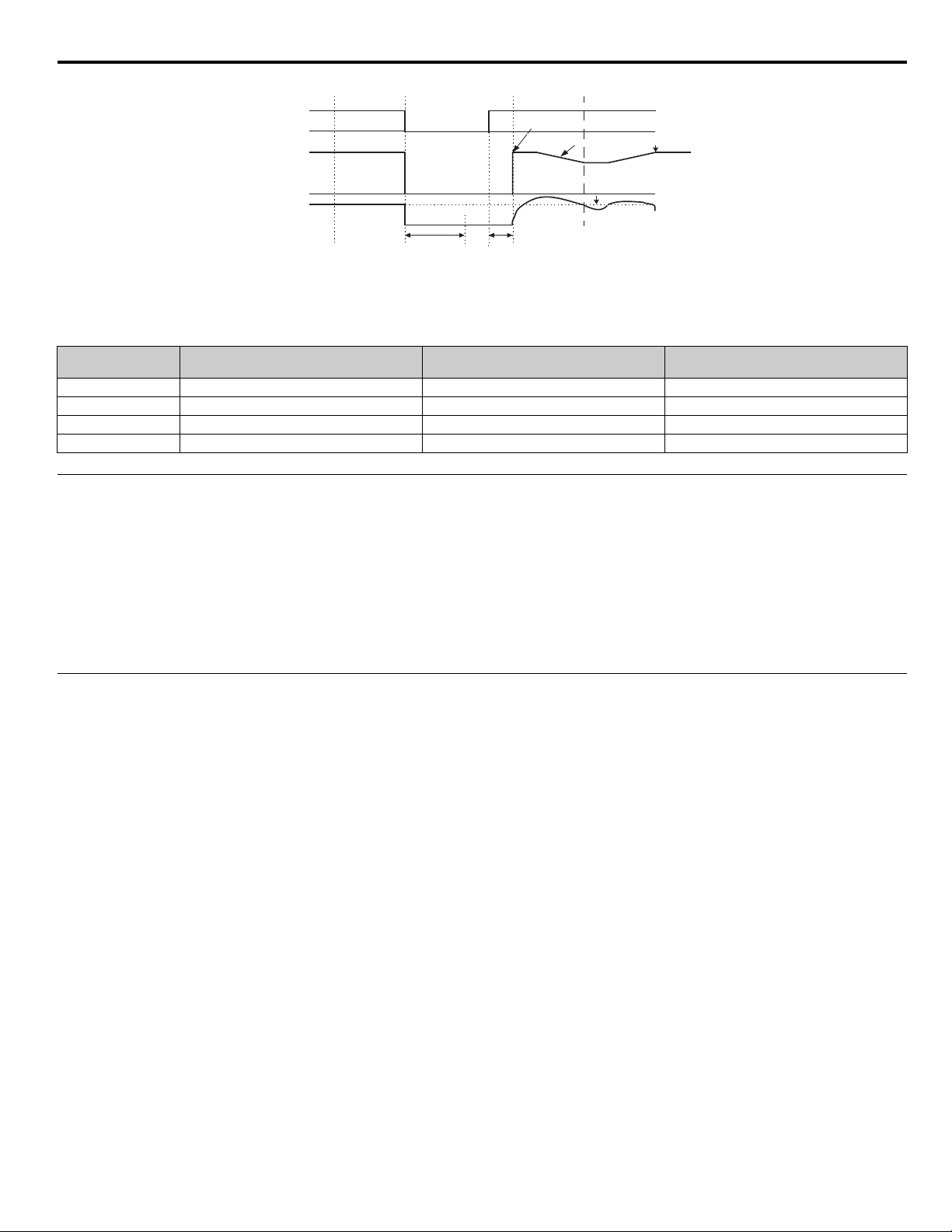
Figure 1.24
AC power supply
Output frequency
Output current
OFFON
Output frequency before power loss
Set frequency
reference
Minimum baseblock time
(L2-03)
Deceleration speed set in b3-03
b3-02
Speed search operating time
Speed search wait time (b3-05)
Deceleration time set in b3-03
Figure 24. Speed Search (Current Detection Method) after momentary power loss
where the power loss time exceeds the minimum baseblock time
Setting of b3-01
0 No Yes - Speed Estimation Yes - Speed Estimation
1 Yes - Speed Estimation Yes - Speed Estimation Yes - Speed Estimation
2 No Yes - Current Detection Yes - Current Detection
3 Yes - Current Detection Yes - Current Detection Yes - Current Detection
Automatic Speed Search for all RUN
commands
Automatic Speed Search after
momentary power loss and baseblock
Speed Search Used for Run with
programmed multi-function input
◆ b3-02 Speed Search Deactivation Current
Setting Range: 0 ~ 200% of the iQpump drive rated output current
Factory Default: 120% of the iQpump drive rated output current
When using the current detection method of Speed Search, parameter b3-02 sets the current level that will determine when the search is
complete and the rotor and output speeds match. When the output frequency is higher than the actual rotor speed, the slip causes the
current to be high. As the output frequency is lowered, the closer it comes to the rotor speed, the lower the current draw will be. When the
output current drops below the level as set in b3-02 (100% = iQpump drive Rated Current) the output frequency stops decreasing and
normal operation resumes.
◆ b3-03 Speed Search Deceleration Time
Setting Range: 0.1 ~ 10.0 s
Factory Default: 2.0 s
Parameter b3-03 sets the deceleration ramp used by the current detection method of Speed Search when searching for the motor’s rotor
speed. Even if Speed Search 2 is selected, for Speed Search at start, the time entered into b3-03 will be the time to decelerate from
maximum frequency (E1-04) to minimum frequency (E1-09).
YASK AWA TM.iQp.07 iQpump Controller Programming Manual 29
Page 30

◆ b3-05 Speed Search Delay Time
Setting Range: 0.0 ~ 20.0 s
Factory Default: 0.2 s
In cases where an output contactor is used between the iQpump drive and the motor, extra waiting time is provided after power returns
and before Speed Search is performed. This extra time allows for the contactor to operate. When Speed Search at start is used, b3-05 will
serve as the lower limit of the Minimum Baseblock Time (L2-03).
◆ b3-14 Bi-Directional Speed Search Selection
Setting Description
0Disabled
1 Enabled (factory default)
The b3-14 parameter can be used to turn off the bi-directional capabilities of the Speed Estimation form of Speed Search. By turning off
the bi-directional capability, the speed search will only try to match the speed in the last known direction.
30 YASK AWA TM.iQp.07 iQpump Controller Programming Manual
Page 31

b4 Delay Timers
Multi-function Contact
Input: Timer Function
Multi-function Contact
Output: Timer Function
b4-01
b4-01
b4-02
ON (CLOSED)
OFF (OPEN)
ON (CLOSED
OFF (OPEN)
b4-02
The iQpump drive has an internal timer function that operates independently from the drive. A digital input must be programmed to be a
timer start input by setting H1-0x = 18. A digital output must be programmed as a timer output by setting H2-0x = 12. (Not to be
confused with the “Wait to Run Time” in b1-11.)
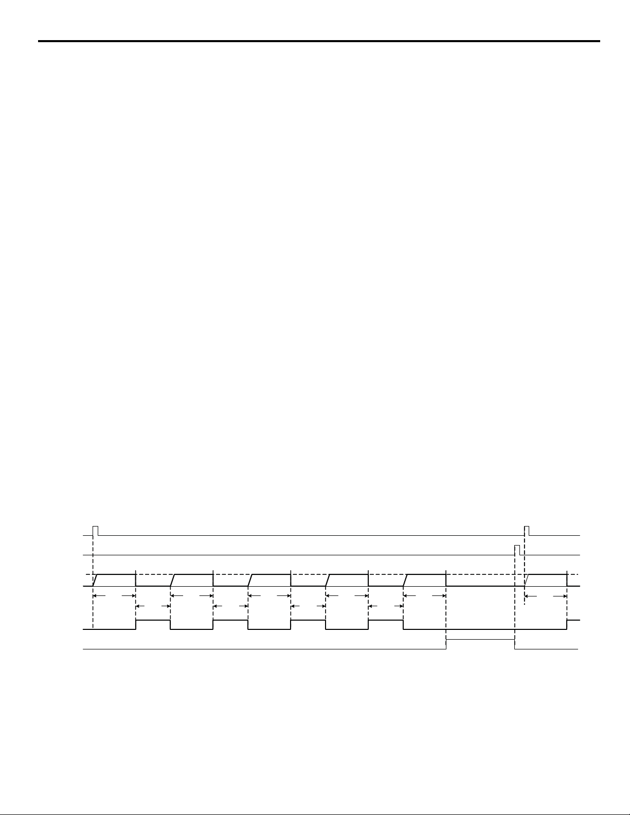
◆ b4-01 Timer Function ON-Delay Time
Setting Range: 0.0 ~ 3000.0 s
Factory Default: 0.0 s
The timer start input (H1-0x = 18) must be held on for at least the time specified in parameter b4-01 before the digital output programmed
as the timer output will close. See Figure 25. for timing details.
◆ b4-02 Timer Function OFF-Delay Time
Setting Range: 0.0 ~ 3000.0 s
Factory Default: 0.0 s
The timer start input (H1-0x = 18) must be held off for at least the time specified by b4-02 before the digital output programmed as the
timer output will open. See Figure 2 5. for timing details.
Figure 1.25
Figure 25. Timing Diagram of Timer Function
YASK AWA TM.iQp.07 iQpump Controller Programming Manual 31
Page 32

b5 PI Function
Option Card
Serial Com
Terminal A1
D1-01
D1-04
D1-02
Output
frequency
P
1/t
1/t
Z
-1
b1-01
1
2
3
Frequency Reference
using multi-step
command
Frequency reference
(U1-01)
PI Set Point
(U1-38)
Proportional
gain
b5-02
I-time
b5-03
I - limit
b5-04
PI Limit
b5-06
PI delay time
b5-08
PI offse
t
(b5-07)
+
+
+
+
PI output monitor
(U1-37)
b5-01=0
ON
PI control is OFF under t he following
conditions:
- b5-01=0
- H3-xx=19 and the terminal status is
ON
Upper limit
Fmax x109%
+
+
b5-01=3
b5-01=1
Lower limit 0
4
Integral Hold
H1-xx=31
Integral Reset
H1-xx=30
PI Output
Characteristic
b5-09
1
0
PI SFS
b5-17
PI SFS cancel
H1-xx=34
0
1
P1-03
Scaling
Terminal A1
Terminal A2
PI Differential
Fdbk. H3-09=16
1
0
H3-09=B
1
0
1
0
PI Different ial
Fdbk. H3-09=16
PI Different ial
Fdbk. H3-09=16
Z
-1
1
0
1
0
PI Input
Caracteristic
H1-xx=35
1
0
Z
-1
PI SFS
b5-17
PI SFS cancel
H1-xx=34
0
1
Scaling
PI Input
(U1-36)
+
0
1
PI Different ial
Fdbk. H3-09=16
PI Feedback
(U1-24)
Scaling
10
10
b5-07
0
1
+
+
PI Different ial
Fdbk. H3-09=16
-
+
+
+
b5-10
PI Output
Gain
PI offset
H3-09=16
SFS
OFF
PI Different ial
Fdbk. H3-09=16
Characteristic
H1
P1-06
Minimum
Pump Speed
Speed Command / PI Setpoint
PI Setpoint
PI Feedback
The capability to accept an analog signal as feedback for a PI (Proportional + Integral) control function is built into the drive.
Figure 1.26
The analog feedback to the iQpump drive for the PI control is via the A2 terminal. The iQpump drive must be programmed (H3-09 = “B:
PI Feedback”) to use terminal A2 as feedback for the PI functionality of the drive.
The PI Setpoint can be configured to come from one of many different inputs or parameters. Table 6 on page 32 describes the options for
originating the PI Setpoint.
The PI Setpoint will be read from:
MEMOBUS/Modbus Register 06H 0 ON N/A
In some situations there are two feedback inputs. The drive can be programmed to maintain a set differential between two analog signals.
If input A2 is configured as a “PI Differential Mode” (H3-09 = “16: PI Differential”), then the iQpump drive will maintain a set
difference between the measurements read on inputs A1 and A2. This differential setpoint is programmed by parameter (b5-07).
32 YASK AWA TM.iQp.07 iQpump Controller Programming Manual
Figure 26. PI Block Diagram
Table 6 PI Setpoint Options
Status of b5-18 =
If these conditions are true
Status of MEMOBUS /
Modbus Register 0Fh bit 1
Status of b1-01 =
Parameter b5-19 1 N/A N/A
D1-01 0 OFF 0
Ter minal A 1 0 OFF 1
Serial Comm. 0 OFF 2
Option PCB 0 OFF 3
Page 33

◆ b5-01 PI Mode
Setting Description
0Disabled
1 Enabled (factory default)
2 Enabled - 2 Zone (dual zone PI enabled)
The iQpump drive can be used as a stand-alone PI controller. If PI functionality is selected by parameter b5-01, the iQpump drive will
adjust its output to cause the feedback from a transmitter to match the PI Setpoint (b5-19). The setting of b5-01 will determine whether PI
functionality is disabled (b5-01 = “0: Disabled”), enabled (b5-01 = “1: Enabled”), enabled - 2 zone (dual zone PI enabled) (b5-01 = 2).
b5-01 = 0, Disabled
PI functionality is disabled.
b5-01 = 1, Enabled (factory default)
PI functionality is enabled.
<0034>
b5-01 = 2, Enabled - 2 Zone (dual zone PI enabled)
<0034>
Enabled - 2 zone.
Provides automatic setpoint and feedback switching for dual zone pumping applications (geothermal).
• Terminal A1 is used as a feedback signal for “Zone 1”.
• Standard PI Feedback (H3-09 = B) as feedback for “Zone 2”.
• Based upon the two feedback levels, the drive determines which setpoint and feedback signal to use.
Figure 1.27
To:
Zone 1
Zone 1
Valve
Moto r
Pump
T1 T2 T3
Motor Leads
Zone 2
Valve
To:
Zone 2
A1
A2
Yaskawa
iQpump Drive
Figure 27. Dual Zone PI
Changes from standard product:
• When the Dual Zone PI is enabled (b5-01 = 2) Terminal A1 becomes the feedback signal for Zone 1.
• Multi-Step Frequency Reference Select digital inputs are ignored (H1-0x = 3 or 4) when the Dual Zone PI is enabled (b5-01 = 2).
• Transducer Loss Detection is enabled on Terminal A1 when b5-01 = 2.
YASK AWA TM.iQp.07 iQpump Controller Programming Manual 33
Page 34

Dual Zone PI Operation:
Set-Pt Zones 1&2
85 PSI
0.00 Hz
82.3 PSI
Set-Point Zone 1
85 PSI
0.00 Hz
82.3 PSI
Set-Point Zone 2
85 PSI
0.00 Hz
82.3 PSI
In order to enable the Dual Zone PI Operation:
b5-01 = 2 The PI Mode Setting Parameter must be set to “Enabled - 2 Zone”.
P1-01 = 0 Simplex mode only.
b5-09 = 0 Output Level Select set to “Normal Output” (Not Inverse PI Control).
When Dual Zone PI Operation is enabled:
• When the drive is in auto mode, the digital operator display will change as noted in Table 6 on page 32.
• Terminal A1 becomes a PI feedback, assigned to Zone 1.
• Standard PI feedback is assigned to Zone 2 (requires H3-09 = B).
• If feedback on Terminal A1 within the P4-17 value of the feedback on Terminal A2, the drive will use the d1-04 parameter as the
setpoint. It will use either Terminal A1 or Terminal A2 as feedback depending on which one is higher. The feedback signal(s) need to
be different for more than 5 seconds before any switching between the two will occur.
• If the feedback on Terminal A1 is more than the feedback on Terminal A2 plus the P4-17 value for more than 5 seconds, the drive will
then operate off of the Zone 1 setpoint (d1-02) and the Zone 1 feedback (Terminal A1).
• If the feedback on Terminal A2 is more than the feedback on Terminal A1 plus the P4-17 value for more than 5 seconds, the drive will
then operate off of the Zone 2 setpoint (d1-03) and the Zone 2 feedback (Terminal A2).
From the main “Auto Mode” display see Table 6 on page 32, if the <Data / Enter> key is pressed, the currently active setpoint will be
editable.
Note: To convert Terminal A1 to a 4 - 20 mA signal, connect a 250 Ohm precision resistor (1/4 Watt or greater) between A1
and AC. Then program H3-02 = 231.3% and H3-03 = 25.0%.
Table 7 Dual Zone PI
Pressure Condition Feedback Signal Setpoint Parameter Used
Zone 1 = Zone 2
(+/- P4-17)
Zone 1 > Zone 2 + P4-17
Whichever is higher
(Terminal A1 or A2)
Whichever is higher
(Terminal A1 or A2)
d1-04
d1-02
“Auto Mode”
Digital Operator Display
Zone 1 < Zone 2 - P4-17
34 YASK AWA TM.iQp.07 iQpump Controller Programming Manual
Whichever is higher
(Terminal A1 or A2)
d1-03
Page 35

Figure 1.28
Run Cmd.
PI Setpoin t
PI
Feedback
Zone 1
(Term A1)
PI Feedback
Zone 2
(Term A1)
PI Feedback
5 sec 5 sec
Short
Disturbance
Zone 1 Valve
Is closed
5 sec
Zone 2 Valve
Is opened
5 sec
Zone 2 Valve
Is closed
5 sec
Zone 1 Valve
Is opened
d1-04 d1-04 d1-04
d1-02
d1-03
Figure 28. Dual Zone PI Operation
Table 8 Related Parameters <0034>
Parameter
No.
d1-02
d1-03
d1-04
Addr. Hex
281
282
283
Parameter Name
Digital Operator Display
Setpoint 2
Setpoint 2
Setpoint 3
Setpoint 3
Setpoint 4
Setpoint 4
Description
Digital preset setpoint 2. Used when b1-01 = 0. Setting units are
affected by P1-02 and P1-03. Also is the Zone 1 PI reference when
b5-01 = 2.
Digital preset setpoint 3. Used when b1-01 = 0. Setting units are
affected by P1-02 and P1-03. Also is the Zone 2 PI reference when
b5-01 = 2.
Digital preset setpoint 4. Used when b1-01 = 0. Setting units are
affected by P1-02 and P1-03. Also is the Zones 1 and 2 PI reference
when b5-01 = 2.
Setting
Range
0.00 ~
P1-02
value
0.00 ~
P1-02
value
0.00 ~
P1-02
value
Factory
Setting
0.00 Programming
0.00 Programming
0.00 Programming
Denotes that parameter can be changed when the drive is running.
Table 9 Parameters <0034>
Parameter
No.
P4-17
<0034>
Addr. Hex
830
Parameter Name
Digital Operator Display
Dual Zone PID Feedback
Bandwidth Range
Dual Zone Range
Description
Determines the detection bandwidth for the dual zone PI control.
Setting
Range
0 ~ 6000.0
(system
units
P1-02)
Factory
Setting
10.0
(system
units
P1-02)
Table 10 Fault <0034>
Fault Display Description Cause Countermeasures
Terminal A1 is being assigned to more than one of the following
oPE13
Ter minal A 1
Programming error
functions:
- Frequency Reference (b1-01 = 1)
- Dual Zone PI is enabled (b5-01 = 2)
- Flow Meter Enabled (P6-01 > 0)
- Level Control Enabled (P8-01 = 1)
Reprogram b1-01, b5-01, P6-01,
or P8-01.
Menu
Location
Menu
Location
Programming
◆ b5-02 Proportional Gain Setting
Setting Range: 0.00 ~ 25.00
Factory Default: 2.00
The proportional gain will apply a straight multiplier to the calculated difference (error) between the PI Setpoint and the measured
transmitter feedback at terminal A2. A large value will tend to reduce the error but may cause instability (oscillations) if too high. A small
value may allow to much offset between the setpoint and feedback (See Figure 29. on following page).
YASK AWA TM.iQp.07 iQpump Controller Programming Manual 35
Page 36

◆ b5-03 Integral Time Setting
Zero
offset with
Integral Action
No Integral With Integral
Measured Feedback
Measured Feedback
Setpoint
Offset
Setpoint
Feedback Feedback
TIME
TIME
Setting Range: 0.0 ~ 360.0 s
Factory Default: 3.0 s
The Integral factor of PI functionality is a time-based gain that can be used to eliminate the error (difference between the setpoint and
feedback at steady state). The smaller the Integral Time set into b5-03, the more aggressive the Integral factor will be. To turn off the
Integral Time, set b5-03 = 0.00.
Figure 1.29
Figure 29. PI Feedback Response Characteristics
◆ b5-04 Integral Limit Setting
Setting Range: 0.0 ~ 100.0%
Factory Default: 100.0%
On some applications, especially those with rapidly varying loads, the output of the PI function may have large oscillations. To suppress
these oscillations, a limit can be applied to the integral factor by programming b5-04.
◆ b5-06 PI Output Limit
Setting Range: 0.0 ~ 100.0%
Factory Default: 100.0%
Places a cap on the output of the PI function. Limiting the PI function may help to prevent large overshoots in the drive’s response to error
(the difference between the setpoint and the feedback).
◆ b5-07 PI Offset Adjustment
Setting Range: -100.0% ~ +100.0%
Factory Default: 0.0%
The PI Offset Adjustment parameter has two different uses. Parameter b5-07 serves different functions depending on whether it is used
on a standard PI loop or a Differential PI loop.
Parameter b5-07 causes an offset to be applied to the output of the PI function in a non-Differential PI loop. Every time the PI output is
updated, the offset (b5-07) is summed with the PI output. This can be used to artificially kick-start a slow starting PI loop.
If the iQpump drive is configured for Differential PI Regulation (H3-09 = “16: PI differential”), then this parameter is the target setpoint
for the differential to be maintained between the signal measured on analog input A1 and the signal measured on analog input A2.
36 YASK AWA TM.iQp.07 iQpump Controller Programming Manual
Page 37

◆ b5-08 PI Primary Delay Time Constant
Setting Range: 0.00 ~ 10.00 s
Factory Default: 0.00 s
Acts as a time based filter that lowers the responsiveness of the PI function, but also makes the function more stable when the setpoint
varies rapidly or when the feedback is noisy.
◆ b5-09 PI Output Level Selection
Setting Description
0 Normal Output (direct acting) (factory default)
1 Reverse Output (reverse acting)
Normally, the output of the PI function causes an increase in motor speed whenever the measured feedback is below the setpoint. This is
referred to as direct acting response. However, if b5-09 = “1: Reverse Output,” the output of the PI function causes the motor to slow
down when the feedback is below the setpoint. This is referred to as reverse acting response.
◆ b5-10 PI Output Gain Setting
Setting Range: 0.0 ~ 25.0
Factory Default: 1.0
Applies a multiplier to the output of the PI function. Using the gain can be helpful when the PI function is used to trim the Speed
Command. Increasing b5-10 causes the PI function to have a greater regulating affect on the speed command.
◆ b5-12 PI Feedback Reference Missing Detection Selection
Setting Description
0Disabled
1Alarm
2Fault (factory default)
Loss of feedback can cause problems to a PI application. The iQpump drive can be programmed to turn on a digital output whenever a
loss of feedback occurs. Feedback Loss Detection (FBL) is turned on by b5-12. When b5-12 = “1: Alarm,” the iQpump drive
acknowledges the loss of feedback without stopping or turning on the fault output (MA-MB). If b5-12 = “2: Fault,” the iQpump drive
coasts to a stop and turns on the fault output if the feedback is determined to be lost.
The Feedback Loss Detection can be disabled during the following conditions:
• Pre-charge Level (P4-01) is set to 0.
• Thrust Bearing acceleration or deceleration.
Note: A Feedback Loss Detection (FBL) will occur when the Thrust Bearing function is enabled and a run command given, P1
Feedback Loss Detection Time (b5-14) is set to 0, and P1 Feedback is below Feedback Loss Detection Level (b5-13).
Function Description
This parameter also allows feedback loss detection to also function as a wire break detection when the signal type is 4 ~ 20mA. The Wirebreak Feedback Loss Detection will still be active when b5-13 = 0%.
Wire break will be detected on Terminal A2 when:
• PI Feedback Loss Detection is enabled (b5-12 = 1 or 2)
• PI is enabled (b5-01 > 0)
• Terminal A2 9s set for PI Feedback (H3-09 = B)
• Terminal A2 is set for 4 ~ 20 mA (H3-08 = 2)
• PI is NOT disabled via Multi-Function Digital Input
• Signal on Terminal A2 goes below 3 mA or above 21 mA for more than 1 s.
Note: Wire break detection on Terminal A2 is unaffected by the gain / bias parameters H3-10 and H3-11.
Wire break will be detected on Terminal A1 when:
<0034>
• PI Feedback Loss Detection is enabled (b5-12 = 1 or 2)
YASK AWA TM.iQp.07 iQpump Controller Programming Manual 37
Page 38

• PI is enabled (b5-01 > 0)
• Dual Zone PI is enabled (b5-01 = 2, P1-01 = 0, b5-09 = 0, and H3-09 = B)
• PI is NOT disabled via Multi-Function Digital Input
• Signal on Terminal A1 goes below -6.25% or above 106.25% for more than 1 s.
Note: Wire break detection on Terminal A1 occurs after the gain / bias parameters (h3-02 and H3-03) are applied.
Feedback Loss (wire-break):
The drive will then react depending on how parameter b5-12 is programmed. However, if b5-12 is set to “fault” (b5-12 = 2), the drive will
only fault when running in “Auto” mode. A warning will only be displayed if the drive is not running, or is running in “Hand” mode.
Feedback Loss (standard):
The drive will then react depending on how parameter b5-12 is programmed. However, if b5-12 is set to “fault” (b5-12 = 2), the drive will
only fault when running in “Auto” mode. A warning will only be displayed if the drive is running in “Hand” mode.
Note: To convert terminal A1 to a 4 ~ 20 mA signal, connect a 250 Ohm precision resistor (1/4 W or greater) between A1 and
AC. Then program H3-02 = 231.2% and H3-03 = 25.0%.
Table 11 Related Parameters
Parameter
No.
b5-12 1B0
b5-13 1B1
b5-14 1B2
Addr.
Hex
Parameter Name
Digital Operator Display
PI Feedback Reference Missing
Detection Selection
Fb los Det Sel
PI Feedback Loss Detection
Level
Fb los Det Lvl
PI Feedback Loss Detection
Time
Fb los Det Time
Description
0: Disabled
1: Alarm
2: Fault
Sets the PI feedback lost detection level as a percentage of maximum
frequency (E1-04).
Sets the PI feedback loss detection delay time in terms of seconds.
Setting
Range
0 ~ 2 2 Programming
0 ~ 100% 0% Programming
0.0 ~
25.5 s
Table 12 Related Fault
Fault Display Description Cause Countermeasure
FBL Feedback
Loss
PI Feedback Loss PI Feedback source is not installed correctly or is not working.
Check to insure the PI Feedback source is installed and working
properly.
Table 13 Multi-Function Output Setting
Setting Description
4A
Transducer Loss
Closed: During a “Feedback Loss Alarm”
Closed: During a “FBL - Feedback Loss Fault”
◆ b5-13 PI Feedback Loss Detection Level
Setting Range: 0 ~ 100%
Factory
Setting
2.0 s Programming
Menu
Location
Factory Default: 0%
Refer to parameter b5-13 in appendix A for description details.
◆ b5-14 PI Feedback Loss Detection Time
Setting Range: 0.0 ~ 25.0 s
Factory Default: 2.0 s
The iQpump drive interprets feedback loss whenever the feedback signal drops below the value of b5-13 and stays below that level for at
least the time set into b5-14. See Figure 1.30 for timing details.
38 YASK AWA TM.iQp.07 iQpump Controller Programming Manual
Page 39

Figure 1.30
Measured
T
Feedback
Loss Output
T
b5-13
T = b5-14
Feedback
Loss Digital Output
ON (CLOSED)
OFF (OPEN)
TIME
Feedback
Figure 30. Loss of PI Feedback Feature
◆ b5-17 PI Accel / Decel Time
Setting Range: 0.0 ~ 25.5 s
Factory Default: 0.0 s
This is a soft start function that is applied to the PI Setpoint analog input. Instead of having nearly instantaneous changes in signal levels,
there is a programmed ramp applied to level changes. When changing setpoints the error can be limited by gradually ramping the setpoint
through the use of parameter b5-17.
◆ b5-32 Integrator Ramp Limit <0034>
The Integrator Ramp Limit provides a way to tune the PI loop so that it is less reactive to sudden spikes and dips in the feedback signal.
Sometimes in a pressure regulated system with a very long piping system, pressure waves can develop which without this feature, can
cause instability in the PI controller.
This feature only applies to the drive’s standard PI Loop. It will not be applied to the PI Loop associated with water level control (Well
Draw Down Control).
Function Description
<0034>
Integrator Ramp Limit.
When the Integrator Ramp Limit is enabled, the PI Integrator is limited to +/- the b5-32 value of the soft starter output (output frequency
without slip compensation). A b5-32 setting of zero disables this feature and the integrator is allowed to operate normally.
Table 14 Related Parameter
Parameter
No.
b5-32 85F
Addr.
Hex
Parameter Name
Digital Operator Display
Integrator Ramp Limit
Int Ramp Lim
Description
When set to a value greater than zero, the PI Integrator is forced to be
within +/- this amount of the soft starter output
Setting
Range
0.0 ~
10.0 Hz
Factory
Setting
0.0 Hz Programming
Menu
Location
YASK AWA TM.iQp.07 iQpump Controller Programming Manual 39
Page 40

b8 Energy Savings
The energy savings function improves overall system operating efficiency by operating the motor at its highest efficiency. This is
accomplished by continuously monitoring the motor load and adjusting the motor terminal voltage so that the motor always operates near
its rated slip frequency. A motor is most efficient when operating near rated slip conditions.
◆ b8-01 Energy Savings Selection
Setting Description
0 Disabled (factory default)
1 Enabled
When the Energy Savings function is enabled (b8-01 = “1: Enabled”), the iQpump drive reduces the output voltage to the motor below
the voltage value specified by the programmed V/f pattern whenever the motor load is light. Since torque is reduced during this voltage
reduction, the voltage has to return to normal levels when the load returns. The energy savings is realized through improved motor
efficiency. The reduced output voltage causes increased rotor slipping even with a light load. A motor is most efficient when operating
fully loaded (i.e. operating at rated slip).
◆ b8-04 Energy Saving Coefficient Value
Setting Range: 0.0 ~ 655.0
Factory Default: Model Dependent
Parameter b8-04 is used in maximizing motor efficiency. The factory setting will be iQpump drive capacity dependant but can be adjusted
in small amounts while viewing the kW monitor (U1-08) and running the iQpump drive to minimize the output kW. A larger value
typically results in less voltage to the motor and less energy consumption. Too large a value will cause the motor to stall.
◆ b8-05 Power Detection Filter Time
Setting Range: 0 ~ 2000 ms
Factory Default: 20 ms
The Energy Saving function will search out the lowest output voltage in order to achieve minimum output power usage. Parameter b8-05
determines how often the output power (kW) is measured and the output voltage is adjusted.
◆ b8-06 Search Operation Voltage Limit
Setting Range: 0 ~ 100%
Factory Default: 0%
Once Energy Savings is enabled and the optimal energy saving coefficient value has been set, the programmer can have the iQpump drive
further search out the proper voltage to achieve the lowest output power by making minute changes to the output voltage and measuring
the output power every b8-05 ms. Parameter b8-06 sets limits to the range over which the voltage will be adjusted in order to minimize
the power output. Settings too large a value may allow the motor to stall if the load is applied abruptly.
If b8-06 = 0, then the optimum voltage search operation is disabled (but not Energy Savings itself).
40 YASK AWA TM.iQp.07 iQpump Controller Programming Manual
Page 41

C1 Accel / Decel
◆ Acceleration Times
Parameter No. Parameter Name
C1-01 Acceleration Time 1
C1-02 Deceleration Time 1
C1-03 Acceleration Time 2
C1-04 Deceleration Time 2
C1-05 Acceleration Time 3
C1-06 Deceleration Time 3
Setting Range: 0.0 ~ 6000.0 s
Factory Defaults: C1-01 20.0 s
C1-02, C1-03 and C1-04 10.0 s
C1-05 and C1-06 50.0 s
C1-01 (Acceleration Time 1) sets the time to accelerate from zero to maximum speed (E1-04). C1-02 (Deceleration Time 1) sets the time
to decelerate from maximum speed to zero. C1-01 and C1-02 are the factory default active accel / decel “pair”. Another accel / decel pair
(C1-03 and C1-04) exists that can be activated by a multi-function digital input (H1-0x = 7), or specified by a switch over frequency as
programmed in parameter C1-11.
C1-05 (Acceleration Time 3) and C1-06 (Deceleration Time 3) are used during the multiple pumping operation. Refer to P3-12 for more
details.
Acceleration Time: This is the time it takes to accelerate from 0 Hz to Maximum Output Frequency defined by parameter E1-04.
Deceleration Time: This is the time it takes to decelerate from Maximum Output Frequency defined by parameter E1-04 to 0 Hz.
Example: C1-01 Acceleration Time 1 programmed for 30 seconds, E1-04 Maximum Output Frequency set to 60 Hz. It will take the
iQpump Controller 20 seconds to accelerate from 0 to 40 Hz (40 Hz ÷ 60 Hz x 30 s = 20 s).
Example: C1-02 Deceleration Time 1 programmed for 50 seconds, E1-04 Maximum Output Frequency set to 60 Hz. It will take the
iQpump Controller 10 seconds to decelerate from 60 to 30 Hz (30 Hz ÷ 60 Hz x 50 s = 25 s).
• Thrust Bearing Operation uses a separate acceleration time defined by parameter P4-04. Once Thrust frequency is reached, the iQpump
drive returns to its normal acceleration time set by C1-01.
• Pre-charge mode uses C1-01 as its acceleration time.
• Hand Mode Operation uses C1-01 and C1-02 for acceleration and deceleration time.
• Auto Mode can use acceleration time C1-05 and deceleration time C1-06, depending on parameter P3-12 setting (see section. P3-12
Delta Setpoint Feedback Acc / Dec Changeover on page 183.)
◆ C1-09 Fast Stop Time
Setting Range: 0.0 ~ 6000.0 s
Factory Default: 10.0 s
A special deceleration parameter is available for use with emergency or fault operations. Parameter C1-09 will set a special deceleration
that can be operated by closing a digital input configured as H1-0x = 15 or H1-0x = 17. A digital input configured as H1-0x = 15 will look
for a switch closure before initiating the Fast Stop operation. A digital input configured as H1-0x = 17 will look for the switch opening
before initiating the Fast Stop operation.
Unlike a standard deceleration time, once the Fast Stop operation is initiated even momentarily, the iQpump drive cannot be re-operated
until the deceleration is complete, the Fast Stop input is cleared, and the Run command is cycled.
The C1-05 (Acceleration Time 3) and C1-06 (Deceleration Time 3) are used during the multiplex pumping operation. Refer to P3-12 for
more details.
YASK AWA TM.iQp.07 iQpump Controller Programming Manual 41
Page 42

◆ C1-11 Accel / Decel Switch Frequency
cy
Time
C1-11
C1-03 Rate C1-01 Rate
C1-02 Rate C1-04 Rate
Setting Range: 0.0 ~ 200.0 Hz
Factory Default: 0.0 Hz
The iQpump drive can be programmed to automatically switch between the two sets of Accel / Decel parameters on the fly. No digital
input is required. If parameter C1-11 is set to a frequency other than zero, the iQpump drive will use Acceleration 1 and Deceleration 1
whenever the output frequency is equal to or above the value of C1-11 and use Acceleration 2 and Deceleration 2 whenever the output
frequency is below the value of C1-11.
A multi-function input programmed as “Multi-Acc / Dec 1” will have priority over C1-11. For example, if the output frequency is greater
than the value of C1-11 but a digital input configured as “Multi-Acc / Dec 1” is closed then Acceleration 2 and Deceleration2 are active.
Figure 1.31
Output
Frequen
Figure 31. Accel / Decel Switch Frequency Operation
42 YASK AWA TM.iQp.07 iQpump Controller Programming Manual
Page 43

C2 S-Curve Acc
Output Frequency
Frequency Reference
Output Frequency
S-curve Characteristic
TIME
Time (Tsc)
Speed Command
Overall Aceleration Time Active Acceleration Time
C2-01()C2-02()+
2
------------ ------------ ------------- ---------
+=
FWD Run Command
REV Run Command
Forward
Acceleration
t
t
t
Reverse
C2-01
C2-02
Output Frequency
TIME
◆ S-Curve Characteristics
Parameter No. Parameter Name
C2-01 S-Curve Characteristic at Start
C2-02 S-Curve Characteristic at Stop
Setting Range: 0.00 ~ 2.50 s
Factory Default: 0.20 s
Parameters C2-01 and C2-02 will affect the acceleration rate of the output frequency in order to reduce shock to the load. The S-curve
addition to the acceleration profile can ramp the acceleration rate from a 0 to the rate specified by the active Acceleration Time (C1-01 or
C1-03) and back to 0.
Figure 1.32
The S-Curve transition into and out of the active acceleration rate can be programmed independently. C2-01 will ramp up the acceleration
from no acceleration up to the rate of C1-01 or C1-03. C2-02 will ramp the acceleration rate from the rate of C1-01 or C1-03 back down
to no acceleration (constant speed). The use of S-Curve characteristics will lengthen the overall acceleration time as follows:
Figure 1.33
Figure 33. S-Curve Characteristic Timing Diagram
YASK AWA TM.iQp.07 iQpump Controller Programming Manual 43
Figure 32. S-curve Characteristic Timing Diagram
Page 44

C4 Torque Comp
◆ C4-01 Torque Compensation Gain
Setting Range: 0.00 ~ 2.50
Factory Default: 1.00
Refer to parameter C4-01 in Appendix A for description details.
◆ C4-02 Torque Compensation Primary Delay Time
Setting Range: 0 ~ 10000 ms
Factory Default: 200 ms
The Torque Compensation function compensates for insufficient torque production at start-up and during low speed operation. The
iQpump drive will detect increases in the motor load by monitoring the output current and compensate by increasing the output voltage.
The increased output voltage leads to an increase in usable torque.
Parameter C4-01 sets the aggressiveness of the compensation for IR (resistive) and IL (inductive) losses in the motor windings, which are
more pronounced at lower speeds. Normally C4-01 does not need to be changed but may require adjustment in the following cases:
• If the iQpump drive to motor cable is long, increase C4-01
• If the motor capacity is smaller than the iQpump drive capacity, increase C4-01
• If the low speed motor performance is unstable, decrease C4-01.
• If the output current level exceeds the drive’s rated current while operating at low speeds, increase C4-01
Parameter C4-02 determines how quickly the Torque Compensation function will react to situations of insufficient torque. Again, C4-02
will not normally require adjustment except for the following situations:
• If the motor vibrates, increase C4-02
• If the motor response is sluggish (and possibly stalls), decrease C4-02
Important: Performing Auto-tuning can enhance low speed performance.
44 YASK AWA TM.iQp.07 iQpump Controller Programming Manual
Page 45

C6 Carrier Frequency
◆ C6-02 Carrier Frequency Selection
Setting Description
0 Low Noise
1 Fc = 2.0 kHz
2 Fc = 5.1 kHz
3 Fc = 8.0 kHz
4 Fc = 10.0 kHz
FProgram
*The factory default setting is model dependent
Parameter C6-02 sets the switching frequency of the drive’s output transistors. It can be changed in order to reduce audible noise and also
reduce leakage current. Cases that may require adjustment to the C6-02 are:
• If the wiring length between the iQpump drive and the motor is long, decrease the carrier frequency
Wiring Length 328 ft or less Over 328 ft
C6-02 (carrier frequency) setting 1 ~ 4 (10 kHz max.) 1 ~ 2 (5 kHz max.)
• If speed and torque are inconsistent at low speeds, decrease the carrier frequency
• If leakage current from the iQpump drive is large, decrease the carrier frequency
• If the audible motor noise is too great, increase the carrier frequency (may require iQpump drive current derating)
When parameter C6-02 is set to “0: Low Noise” the iQpump drive uses a carrier frequency of 2 kHz and reduces the motor audible noise
by approximately 5 db. over the conventional 2 kHz setting (C6-02 = 1). The iQpump drive modulates the nominal PWM pattern to
achieve the lower noise. This setting is normally used with high starting torque loads that are frequently started and stopped or,
applications where leakage current needs to be minimized and motor audible noise is important.
YASK AWA TM.iQp.07 iQpump Controller Programming Manual 45
Page 46

Figure 1.34
CC arrie r F requenc y P arame ter F ac tor y De fa ults :
208V – 240V Drive s 480V Drives
Model
CIMR-P7
C6-02
Carrier
Frequency
(kHz)
C6-03
Carrier Frequency
(kHz)
Model
CIMR-P7
C6-02
Carrier
Frequency
(kHz)
C6-03
Carrier Frequency
(kHz)
20P4 3 8.0 kHz* 40P4 3 8.0 kHz*
20P7 3 8.0 kHz* 40P7 3 8.0 kHz*
21P5 3 8.0 kHz* 41P5 3 8.0 kHz*
22P2 3 8.0 kHz* 42P2 3 8.0 kHz*
23P7 3 8.0 kHz* 43P7 3 8.0 kHz*
25P5 3 8.0 kHz* 44P0 3 8.0 kHz*
27P5 3 8.0 kHz* 45P5 3 8.0 kHz*
2011 3 8.0 kHz* 47P5 3 8.0 kHz*
2015 3 8.0 kHz* 49P0 3 8.0 kHz*
2018 3 8.0 kHz* 4011 3 8.0 kHz*
2022 3 8.0 kHz* 4015 3 8.0 kHz*
2030 3 8.0 kHz* 4018 3 8.0 kHz*
2037 2 5.1 kHz 4022 3 8.0 kHz*
2045 2 5.1 kHz 4024 3 8.0 kHz*
2055 3 8.0 kHz* 4030 3 8.0 kHz*
2075 1 2.0 kHz 4037 3 8.0 kHz*
2090 1 2.0 kHz 4045 3 8.0 kHz*
2110 1 2.0 kHz 4055 2 5.1 kHz
4075 2 5.1 kHz
4090 3 8.0 kHz*
4110 2 5.1 kHz
4132 2 5.1 kHz
4160 2 5.1 kHz
4185 1 2.0 kHz
4220 1 2.0 kHz
4300 1 2.0 kHz
* = when an option card is installed, C6-03 max is 7.0 kHz.
Figure 34. Carrier Frequency Parameter Factory Defaults
◆ Carrier Frequency Limit
Parameter No. Parameter Name
C6-03 Carrier Frequency Upper Limit
Setting Range: 0.4 ~ 10.0 kHz
Factory Default: Model Dependent
46 YASK AWA TM.iQp.07 iQpump Controller Programming Manual
Page 47

d1 Setpoint and Jog References
RUN
Multi-step
Reference 1 Input
Multi-step
Reference 2 Input
Closed
Open
Closed
Open
Closed
Open
Closed
Open
Jog Input
Output
Speed
t
d1-01
d1-02
d1-03
d1-04
d1-17
Preset
References
Multi-step
SP 1 Input
Multi-step
SP 2 Input
*
◆ Setpoint References
Parameter No. Parameter Name
d1-01 Setpoint Reference 1
d1-02 Setpoint Reference 2
d1-03 Setpoint Reference 3
d1-04 Setpoint Reference 4
Setting Range: 0.00 ~ P1-03 Value
Factory Default: 0.00
Figure 1.35
Figure 35. Setpoint and Jog Reference Timing Diagram
* Available only with an LCD operator (JVOP-160).
◆ d1-17 Jog Frequency Reference (LCD Operator Function Only JVOP-160)
Setting Range: 0.00 ~ E1-04 Value
Factory Default: 0.00 Hz
The iQpump drive can be programmed to utilize digital inputs to change between four setpoint and a jog references. It is a two-step
process to set the iQpump drive up for setpoint point and jog references. First, d1-01 through d1-04 and d1-17 must be programmed with
the desired setpoint references and the desired jog reference, respectively. Next, up to three of the drive’s digital inputs (Terminals S3
through S7) need to be programmed (via parameters H1-01 to H1-05) and wired (to normally open contacts) as Multi-step SP1, Multistep SP2, and Jog Frequency.
Table 15 Preset Speed Truth Table
Preset Reference
# Shown for H3-13 = “0: Main Fref TA1”; A1 and A2 are reversed if H3-13 = “1: Main Fref TA2”
As shown in Table 15 on page 47, it is possible to use analog inputs in place of Setpoint Reference 1 and Setpoint Reference 2.
YASK AWA TM.iQp.07 iQpump Controller Programming Manual 47
Terminal
programmed as
Multi-step SP1
1OFFOFF
2ONOFF
3 OFF ON Setpoint Reference 3 (d1-03)
Terminal
programmed as
Multi-step SP2
Details
Setpoint Reference 1 (d1-01) or analog input A1
(determined by b1-01, see page 47)
Setpoint Reference 2 (d1-02) or analog input A2
(determined by H3-09, see page 47)
4 ON ON Setpoint Reference 4 (d1-04)
#
#
Page 48

• If b1-01 = “1: Terminals” then the analog input A1 will be used instead of Setpoint Reference 1 for the first preset Setpoint. If b1-01 =
“0: Operator,” then Setpoint Reference 1 will be used.
• If H3-09 = “2: Aux Reference” then the analog input A2 will be used instead of Setpoint Reference 2 for the second preset Setpoint. If
H3-09 = 2 then Setpoint Reference 2 will be used. This is only available when the iQpump drive is operating in the speed mode.
Important: The programming of d1-01 through d1-04 and d1-17 will be affected by the setting of P1-02 and o1-03, respectively. The
programming of these parameters will be in the units specified by Display Scaling parameter (P1-02 and o1-03).
Note: This function is only used with the LCD operation, not used with HOA operator.
48 YASK AWA TM.iQp.07 iQpump Controller Programming Manual
Page 49

d2 Reference (Speed Command) Limits
q
p
p
Note: See also the “Sleep” function in Figure 1.19 for alternate “lower limit” implementation.
d2-01
d2-02
Operating
Range
◆ d2-01 Frequency Reference Upper Limit
Setting Range: 0.0 ~ 110.0%
Factory Default: 100.0%
Refer to parameter d2-01 in Appendix A for description details.
◆ d2-02 Frequency Reference Lower Limit
Setting Range: 0.0 ~ 110.0%
Factory Default: 0.0%
The use of parameters d2-01 and d2-02 places limitations on the speed command that the iQpump drive will accept. The parameters are
set in units of percentage of the maximum frequency (E1-04) and provide limits on any remote speed command input. By entering upper
or lower frequency limits, the iQpump drive programmer can prevent operation of the iQpump drive above or below levels that may cause
resonance, equipment damage or discomfort (see also parameter d3-0X). For example, limits may be needed to prevent low speed
operation of: Cooling tower fans with gear boxes, pumps with pressure dependent seals, or AHUs with minimum delivery requirements.
Figure 1.36
Internal S
eed Command
-
-
Frequency Reference Upper Limit
Fre
uency Reference Lower Limit
Set S
eed Command
Figure 36. Frequency Reference Upper and Lower Limit Effects on the Speed Command
◆ d2-03 Master Speed Reference Lower Limit
Setting Range: 0.0 ~ 110.0%
Factory Default: 0.0%
Unlike Frequency Reference Lower Limit (d2-02) which will affect the speed command no matter where it is sourced from (i.e. analog
input, preset speed, jog speed, etc.), the Master Speed Reference Lower Limit (d2-03) sets a low speed threshold that will only affect the
analog input that is the active master speed frequency (as determined by parameter H3-13 and H3-09). This parameter allows a minimum
speed to be programmed for the master reference while allowing a lower speed to be set as a jog reference. If the speed commanded by
the active master speed frequency is below the setting of d2-03, then the iQpump drive will operate at the speed specified by d2-03.
YASK AWA TM.iQp.07 iQpump Controller Programming Manual 49
Page 50

d3 Jump Frequencies
◆ Jump Frequencies
Parameter No. Parameter Name
d3-01 Jump Frequency 1
d3-02 Jump Frequency 2
d3-03 Jump Frequency 3
Setting Range: 0.0 ~ 200.0 Hz
Factory Default: 0.0 Hz
◆ d3-04 Jump Frequency Width
Setting Range: 0.0 ~ 20.0 Hz
Factory Default: 1.0 Hz
In order to avoid continuous operation at a speed that causes resonance in driven machinery, the iQpump drive can be programmed with
jump frequencies that will not allow continued operation within specific frequency ranges. If a speed is commanded that falls within a
dead band, or Jump Frequency, the iQpump drive will clamp the frequency reference just below the dead band and only accept higher
speed commands when the commanded speed rises above the upper end of the dead band, for increasing references. Similarly, the
iQpump drive will clamp the frequency reference just above the dead band and only accept lower speed commands when the command
speed falls below the lower end of the dead band, for decreasing references.
Figure 1.37
d3-03
d3-03
-
d3-04
Command
Accepted Speed
d3-01
d3-04
-
d3-04
User Speed
Command Input
d3-04
Figure 37. Jump Frequency Characteristics
Setting the center point of the dead band with the d3-01 through d3-03 parameters and setting the width of the dead band with parameter
d3-04 determines the dead band characteristics. The programmer can set up to three Jump Frequencies. If multiple Jump Frequencies are
programmed the following rule applies:
d3-01 < = d3-02 < = d3-03
50 YASK AWA TM.iQp.07 iQpump Controller Programming Manual
Page 51

E1 V/f Pattern
◆ E1-01 Input Voltage Setting
Setting Ranges: 155.0 V ~ 255.0 V (208 V / 240 V Models)
310.0 V ~ 510.0 V (480 V Models)
Factory Defaults: 208.0 V (208 V Models)
240.0 V (240 V Models)
480.0 V (480 V Models)
Set the Input Voltage parameter (E1-01) to the nominal voltage of the connected AC power supply. This parameter adjusts the levels of
some protective features of the iQpump drive (i.e. Overvoltage, Stall Prevention, etc.). E1-01 also serves as the Maximum / Base Voltage
used by the Preset V / Hz curves (E1-03 = 0 ~ D).
◆ E1-03 V/f Pattern Selection
Setting Description
050 Hz
1 60 Hz Saturation
2 50 Hz Saturation
372 Hz
450 Hz VT1
550 Hz VT2
660 Hz VT1
760 Hz VT2
850 Hz HST1
950 Hz HST2
A60 Hz HST1
B60 Hz HST2
C90 Hz
D120 Hz
E 180 Hz (invalid - OPE2 fault will occur)
F Custom V/f (factory default
FF Custom w/o limit
, with parameter values per setting 1)
The iQpump drive operates utilizing a set V/f pattern to determine the appropriate output voltage level for each commanded speed. There
are 14 different preset V/f patterns to select from with varying voltage profiles, saturation levels (frequency at which maximum voltage is
reached), and maximum frequencies.
There are also settings for Custom V/f patterns that will allow the programmer to manually set (“Customize”) the V/f pattern using
parameters E1-04 through E1-13.
Using parameter E1-03, the programmer can select one of the preset V/f patterns or chose between a custom V/f pattern with an upper
voltage limit (E1-03 = “F: Custom V/f”) and a custom V/f pattern without a voltage limit (E1-03 = “FF: Custom w/o limit”).
YASK AWA TM.iQp.07 iQpump Controller Programming Manual 51
Page 52

Table 16 Preset V/f Patterns
(Hz)
(V)
230
17
10
01.32.5 50
0
230
(V)
28
22
15
13
(Hz)
01.32.5 50
9
8
(Hz)
01.53.0 50 60
17
10
2
1
F
(V)
230
230
(V)
28
22
17
13
(Hz)
01.53.0
B
A
60
(Hz)
01.53.0 60 72
17
10
3
(V)
230
(Hz)
01.53.0 60 90
17
10
C
(V)
230
230
(V)
57
40
10
9
(Hz)
0 1.3 25 50
5
4
(Hz)
01.53.0 60 120
17
10
D
(V)
230
230
(V)
57
40
10
9
(Hz)
0 1.5 30 60
7
6
Specifications E1-03 V/f Pattern *1 Specifications E1-03 V/f Pattern *1
High Starting
Torque 1
8
General-
purpose
Va ri a bl e
Tor qu e
50 Hz 0
60 Hz Saturation
50 Hz Saturation 2
72 Hz 3
Va r i ab l e
Torque 1
50 Hz
Va r i ab l e
Torque 2
Va r i ab l e
Torque 1
50 Hz
High Starting
Torque 2
9
High
1
F
Starting
Torque *2
High Starting
Torque 1
A
60 Hz
High Starting
Torque 2
B
90 Hz C
4
High Speed
5
Operation
120 Hz D
6
60 Hz
Va r i ab l e
Torque 2
7
If one of the custom V/f patterns is selected, then parameters E1-04 through E1-13 will determine the V/f pattern.
Table 18, Table 19 and Table 19 on page 55 is for 240 V class units only. For 480 V class units multiply the voltage value by 2.
Important: When a factory Initialization is performed, the setting of E1-03 is unaffected but the settings of E1-04 through E1-13 are
returned to their factory default settings.
52 YASK AWA TM.iQp.07 iQpump Controller Programming Manual
Page 53

◆ E1-04 Maximum Output Frequency
Setting Range: 0.0 ~ 120.0 Hz
Factory Default: 60.0 Hz
Refer to parameter E1-04 in Appendix A for description details.
◆ E1-05 Maximum Output Voltage
Setting Ranges: 0.0 ~ 255.0 V (240 V Models)
0.0 ~ 510.0 V (480 V Models)
Factory Defaults: 240.0 V (240 V Models)
480.0 V (480 V Models)
Refer to parameter E1-05 in Appendix A for description details.
◆ E1-06 Base Frequency
Setting Range: 0.0 ~ 120.0 Hz
Factory Default: 60.0 Hz
Refer to parameter E1-06 in Appendix A for description details.
◆ E1-07 Mid Output Frequency A
Setting Range: 0.0 ~ 120.0 Hz
Factory Default: 3.0 Hz
Refer to parameter E1-07 in Appendix A for description details.
◆ E1-08 Mid Output Voltage A
Setting Ranges: 0.0 ~ 255.0 V (240 V Models)
0.0 ~ 510.0 V (480 V Models)
Factory Defaults: 17.2 V (240 V Models)
34.5 V (480 V Models)
Refer to parameter E1-08 in Appendix A for description details.
◆ E1-09 Minimum Output Frequency
Setting Range: 0.0 to 120.0 Hz
Factory Default: 1.5 Hz
Refer to parameter E1-09in Appendix A for description details.
◆ E1-10 Mid Output Voltage
Setting Ranges: 0.0 ~ 255.0 V (240 V Models)
0.0 ~ 510.0 V (480 V Models)
Factory Defaults: 10.3 V (240 V Models)
20.7 V (480 V Models)
Refer to parameter E1-10 in Appendix A for description details.
YASK AWA TM.iQp.07 iQpump Controller Programming Manual 53
Page 54

◆ E1-11 Mid Output Frequency B
Frequency
E1-09 E1-07
E1-06
E1-04
E1-11
Max Voltage E1-05
Mid Voltage B E1-12
Mid Voltage A E1-08
Base Voltage E1-13
Min Voltage E1-10
Min
Freq
Max
q
Base
Freq
Mid
Freq
Mid
Freq B
Freq A
Setting Range: 0.0 ~ 120.0 Hz
Factory Default: 0.0 Hz
Refer to parameter E1-11 in Appendix A for description details.
◆ E1-12 Mid Output Voltage B
Setting Ranges: 0.0 ~ 255.0 V (240 V Models)
0.0 ~ 510.0 V (480 V Models)
Factory Defaults: 0.0 V (240 V Models)
0.0 V (480 V Models)
Top set up custom V/f pattern, program the points shown in the diagram below using parameters E1-04 through E1-13. Be sure that the
following condition is true:
E1-09 ≤ E1-07 ≤ E1-06 ≤ E1-11 ≤ E1-04
◆ E1-13 Base Voltage
Setting Ranges: 0.0 ~ 255.0 V (240 V Models)
0.0 ~ 510.0 V (480 V Models)
Factory Defaults: 0.0 V (240 V Models)
0.0 V (480 V Models)
To set up a custom V/f pattern, program the points shown in the diagram below using parameters E1-04 through E1-13. Be sure that the
following condition is true:
E1-09 ≤ E1-07 ≤ E1-06 ≤ E1-11 ≤ E1-04
Figure 1.38
Figure 38. Custom V/f Pattern Programming Curve
Fre
Increasing the voltage in the V/f pattern increases the available motor torque. However, when setting a custom V/f pattern, increase the
voltage gradually while monitoring the motor current, to prevent:
• Drive faults as a result of motor over-excitation
• Motor overheating or excessive vibration
54 YASK AWA TM.iQp.07 iQpump Controller Programming Manual
Page 55

Table 18, Table 19 and Table 19 on page 55 are for 240 V class units only. For 480 V class units, multiply the voltage values by 2.
Table 17 V/f Pattern Default Settings for Drive Capacity 0.5 ~ 2 HP for 240 V Class
Parameter
No.
E1-03 V/f Pattern Selection — 0123456789ABCDF
E1-04 Max Output Frequency Hz 50.0 60.0 60.0 72.0 50.0 50.0 60.0 60.0 50.0 50.0 60.0 60.0 90.0 120.0 60.0
E1-05 Max Output Voltage V 240.0 240.0 240.0 240.0 240.0 240.0 240.0 240.0 240.0 240.0 240.0 240.0 240.0 240.0 240.0
E1-06 Base Frequency Hz 50.0 60.0 50.0 60.0 50.0 50.0 60.0 60.0 50.0 50.0 60.0 60.0 60.0 60.0 60.0
E1-07 Mid Output Frequency A V 2.5 3.0 3.0 3.0 25.0 25.0 30.0 30.0 2.5 2.5 3.0 3.0 3.0 3.0 3.0
E1-08 Mid Output Voltage A V 17.2 17.2 17.2 17.2 40.2 57.5 40.2 57.5 21.8 27.6 21.8 27.6 17.2 17.2 17.2
E1-09 Min Output Frequency Hz 1.3 1.5 1.5 1.5 1.3 1.3 1.5 1.5 1.3 1.3 1.5 1.5 1.5 1.5 1.5
E1-10 Mid Output Voltage V 10.3 10.3 10.3 10.3 9.2 10.3 9.2 10.3 12.6 14.9 12.6 17.2 10.3 10.3 10.3
E1-11 Mid Output Frequency B Hz000000000000000
E1-12 Mid Output Voltage B V 000000000000000
E1-13 Base Voltage V 000000000000000
For 480 V class units, the value is twice that of 240 V class units.
Name Unit Factory Setting
Table 18 V/f Pattern Default Settings for Drive Capacity 3 ~ 40 HP for 240 V Class
Parameter
No.
E1-03 V/f Pattern Selection — 0123456789ABCDF
E1-04 Max. Output Frequency Hz 50.0 60.0 60.0 72.0 50.0 50.0 60.0 60.0 50.0 50.0 60.0 60.0 90.0 120.0 60.0
E1-05 Max. Output Voltage V 240.0 240.0 240.0 240.0 240.0 240.0 240.0 240.0 240.0 240.0 240.0 240.0 240.0 240.0 240.0
E1-06 Base Frequency Hz 50.0 60.0 50.0 60.0 50.0 50.0 60.0 60.0 50.0 50.0 60.0 60.0 60.0 60.0 60.0
E1-07 Mid. Output Frequency A V 2.5 3.0 3.0 3.0 25.0 25.0 30.0 30.0 2.5 2.5 3.0 3.0 3.0 3.0 3.0
E1-08 Mid. Output Voltage A V 16.1 16.1 16.1 16.1 40.2 57.5 40.2 57.5 20.7 26.4 20.7 26.4 16.1 16.1 16.1
E1-09 Min. Output Frequency Hz 1.3 1.5 1.5 1.5 1.3 1.3 1.5 1.5 1.3 1.3 1.5 1.5 1.5 1.5 1.5
E1-10 Mid. Output Voltage V 8.0 8.0 8.0 8.0 6.9 8.0 6.9 8.0 10.3 12.6 10.3 14.9 8.0 8.0 8.0
E1-11 Mid Output Frequency B Hz000000000000000
E1-12 Mid Output Voltage B V 000000000000000
E1-13 Base Voltage V 000000000000000
For 480 V class units, the value is twice that of 240 V class units.
Name Unit Factory Setting
Table 19 V/f Pattern Default Settings for Drive Capacity 50 ~ 150 HP for 240 V Class
Parameter
No.
E1-03 V/f Pattern Selection – 0123456789ABCDF
E1-04 Max. Output Frequency Hz 50.0 60.0 60.0 72.0 50.0 50.0 60.0 60.0 50.0 50.0 60.0 60.0 90.0 120.0 60.0
E1-05 Max. Output Voltage V 240.0 240.0 240.0 240.0 240.0 240.0 240.0 240.0 240.0 240.0 240.0 240.0 240.0 240.0 240.0
E1-06 Max. Voltage Frequency Hz 50.0 60.0 50.0 60.0 50.0 50.0 60.0 60.0 50.0 50.0 60.0 60.0 60.0 60.0 60.0
E1-07 Mid. Output Frequency A V 2.5 3.0 3.0 3.0 25.0 25.0 30.0 30.0 2.5 2.5 3.0 3.0 3.0 3.0 3.0
E1-08 Mid. Output Voltage A V 13.8 13.8 13.8 13.8 40.2 57.5 40.2 57.5 17.2 23.0 17.2 23.0 13.8 13.8 13.8
E1-09 Min. Output Frequency Hz 1.3 1.5 1.5 1.5 1.3 1.3 1.5 1.5 1.3 1.3 1.5 1.5 1.5 1.5 1.5
E1-10 Mid. Output Voltage V 6.9 6.9 6.9 6.9 5.7 6.9 5.7 6.9 8.0 10.3 8.0 12.6 6.9 6.9 6.9
E1-11 Mid Output Frequency B Hz 000000000000000
E1-12 Mid Output Voltage B V 000000000000000
E1-13 Base Voltage V 000000000000000
For 480 V class units, the value is twice that of 240 V class units.
Name Unit Factory Setting
YASK AWA TM.iQp.07 iQpump Controller Programming Manual 55
Page 56

E2 Motor Setup
Phase-to-phase Resistance at
Insulation Class Temperature
273 + (25 + insulation class temperature) /2
273 + insulation class temperature
E2-05 =
)
(
X
Where: Insulation class temperature is in °C
◆ E2-01 Motor Rated Current
Setting Range: 10% ~ 200%
Factory Default: Model Dependent
The Motor Rated Current parameter (E2-01) is necessary information for the iQpump drive motor protection function. The motor
overload protection parameter L1-01 is enabled by default. In addition, motor rated current is used by the torque compensation function
to insure optimum torque production. Set E2-01 to the full load amps (FLA) value stamped on the motor’s nameplate. During Autotuning, it is required for the operator to enter the motor rated current in parameter T1-04 on the Auto-Tuning menu. If the Auto-tuning
operation completes successfully, the value entered into T1-04 will be also written into E2-01.
For applications employing an iQpump drive that is oversized for the motor, E2-01 may be set as low as 10% of the iQpump drive output
current rating. The AMP value in E2-01, however, must always be greater than the “No Load Current” value in parameter E2-03 or an
OPE02 error will be displayed.
◆ E2-03 No Load Current
Setting Range: Model Dependent (see Appendix B)
Factory Default: Model Dependent
Set E2-03 to the motor no-load current at rated voltage and rated frequency. Consult the motor manufacturer for the proper value if the no
load current is not stated on the motor nameplate.
◆ E2-04 Number of Motor Poles
Setting Range: 2 ~ 48 poles
Factory Default: 2 pole
This parameter sets the number of motor poles used for no-flow detection function and for the calculation of rpm-related parameters.
◆ E2-05 Motor Line-to-Line Resistance
Setting Range: 0.000 ~ 65.000 Ω
Factory Default: Model Dependent
Sets the line-to-line resistance of the motor’s stator winding. Usually determined by performing Auto-tuning. If Auto-tuning cannot be
completed without error, then manually set E2-05 to the value as determined by the motor manufacturer. Remember this value must be
entered as line-line and not line neutral.
56 YASK AWA TM.iQp.07 iQpump Controller Programming Manual
Page 57

F6 Com OPT Setup
◆ F6-01 Operation Selection After Communication Error
Setting Description
0 Ramp to Stop
1 Coast to Stop (factory default)
2Fast-Stop
3 Alarm Only
If a serial communication option board is attached to the iQpump drive at the 2CN connector, the iQpump drive will automatically
monitor the card for any type of communication errors. F6-01 is applicable no matter whether a run command or speed command is
coming via the option board, digital operator, or terminal input. The setting of F6-01 determines whether the communication error is seen
as a fault or an alarm. If F6-01 = “3: Alarm Only,” then the fault output is not energized upon a communication error. All other settings of
F6-01 cause the fault output to energize. The setting of F6-01 does not apply to any of the embedded communication protocols used at the
RS-485 / 422 terminals on the removable terminal board. (See parameters H5-0X.)
◆ F6-02 Option PCB External Fault Detection Selection
Setting Description
0 Always Detected
1 Detected only during operation
(factory default)
◆ F6-03 Option PCB External Fault Stopping Method
Setting Description
0 Ramp to Stop
1 Coast to Stop (factory default)
2Fast-Stop
3 Alarm Only
If an external fault is received from a communication option card, the settings of F6-02 and F6-03 will determine the iQpump drive
operation in reaction to the fault signal. Parameter F6-02 will determine if the external fault is always recognized (F6-02 = “0: Always
Detected”) or only recognized when the Run command is active (F6-02 = “1: Detected only during operation”).
Once the fault is recognized, parameter F6-03 will determine the operation of the drive. If parameter F6-03 is set to anything other then
“3,” the iQpump drive will fault and a stopping sequence is begun. If F6-03 = “3: Alarm Only,” then the external fault is treated like an
alarm. Operation will continue and an EF0 fault will flash on the digital operator.
◆ F6-05 Current Scaling via Communication Option PCB
Setting Description
0 A Display (factory default)
1 100% / 8192 (Drive Rated Current)
A communication option card can read the drive’s DPRAM to access the current monitor. The format of the current reading in the
DPRAM will be determined by parameter F6-05.
F6-05 = “0: A Display” Æ Current is a decimal number corresponding to actual Amperes
F6-05 = “1: 100% / 8192 (Drive Rated Current)” Æ Current reading is a number where 8192 = 100% of the iQpump drive rated
output current
YASK AWA TM.iQp.07 iQpump Controller Programming Manual 57
Page 58

H1 Digital Inputs
◆ Terminal Function Selections
Parameter No. Parameter Name
H1-01 Terminal S3 Function Selection
H1-02 Terminal S4 Function Selection
H1-03 Terminal S5 Function Selection
H1-04 Terminal S6 Function Selection
H1-05 Terminal S7 Function Selection
Setting Range: 0 ~ 86
Factory Defaults: H1-01 = “24: External Fault”
H1-02 = “14: Fault Reset”
H1-03 = “3: Multi-Step SP1” (2-Wire)
xxxxxxx“0: 3-Wire Control” (3-Wire)
H1-04 = “80: Hand Mode”
H1-05 = “84: Pre-charge”
The iQpump drive has five multi-function contact digital inputs. By programming parameters H1-01 through H1-06, the user can assign
specific functions to each input. Below is a table with a complete list of all of the digital input functions. Following the table is a more
detailed description of each of the functions.
Table 20 Digital Input Functions
Parameter setting Function Parameter setting Function
0 3-Wire Control 20-2F External Pump Fault
1 Local / Remote Selection 30 Integral Reset
2 Option / Inv Selection 1 31 Integral Hold
3 Multi-step SP1 34 PI Soft Start Cancel
4 Multi-step SP2 - 6 Not Used 36 Option / Inv Selection 2
7 Multi-Accel / Decel 1 60 Motor Pre-heat
8 External Baseblock N.O. 61 Speed Search 1
9 External Baseblock N.C. 62 Speed Search 2
A Accel / Decel Ramp Hold 64 Speed Search 3
C Terminal A2 Enable 67 Communications Test Mode
F Terminal Not Used 68 High Slip Braking
10 MOP Increase 6A Drive Enable
11 MOP Decrease 6B Comm / Inv Selection
12 Not Used 6C Com / Inv SEL 2
13 Not Used 6D Not Used
14 Fault Reset 6E Not Used
15 Fast Stop N.O. 70 Not Used
17 Fast Stop N.C. 80 Hand Mode
18 Timer Function 81 Disable Sleep Mode
19 PI Disable 82 Sleep Activation
1B Program Lockout 83 Thermostat Fault
1C Not Used 84 Disable Pre-charge
1D Not Used 85 Low Water Level
1E Not Used 86 Fixed Speed Auto
* Input Level Sel - H1-0x = 35, This multi-function input selection for PI Invert has been removed because it interferes with the standard
iQpump operation.
58 YASK AWA TM.iQp.07 iQpump Controller Programming Manual
<0034>
Page 59

Table 21 Parameters <0034>
3-wire control
Stop switch
(NC contact)
Operation switch
(NO contact)
Run command
(run on momentary close)
Stop command
(stop on momentary open)
Sequence input common
SN
Parameter
No.
H1-12 87A
H1-13 87B
H1-14 87C
H1-15 87D
H1-16 87E
■ Function: 3-Wire Control (Setting: 0)
Addr.
Hex
Parameter Name
Digital Operator Display
External Fault 3 Delay Time
EF3 Delay Time
External Fault 4 Delay Time
EF4 Delay Time
External Fault 5 Delay Time
EF5 Delay Time
External Fault 6 Delay Time
EF6 Delay Time
External Fault 7 Delay Time
EF7 Delay Time
Description
Sets the amount of time delay applied to the EF3 fault.
(20 =< H1-01 =< 2F)
Sets the amount of time delay applied to the EF4 fault.
(20 =< H1-02 =< 2F)
Sets the amount of time delay applied to the EF5 fault.
(20 =< H1-03 =< 2F)
Sets the amount of time delay applied to the EF6 fault.
(20 =< H1-04 =< 2F)
Sets the amount of time delay applied to the EF7 fault.
(20 =< H1-05 =< 2F)
Setting
Range
0.00 ~
300.00
0.00 ~
300.00
0.00 ~
300.00
0.00 ~
300.00
0.00 ~
300.00
Factory
Setting
0.00 s Programming
0.00 s Programming
0.00 s Programming
0.00 s Programming
0.00 s Programming
Menu
Location
When one of the digital inputs is programmed for 3-Wire control, that input becomes a Forward / Reverse directional input. Whenever the
input is open, the iQpump drive will be set for forward rotation of the motor shaft. If the input it closed, then the motor shaft will rotate in
the reverse direction whenever a there is a Run input. The S1 and S2 digital inputs will function as a Run and Stop input respectively.
Figure 1.39
Figure 39. Terminal Configuration for 3-Wire Control
Figure 1.40
50 ms min.
Run command
Stop command
Forward/reverse
command
OFF (forward)
Can be either ON or OFF
OFF
(stopped)
ON (reverse)
Motor speed
TIME
Stop Forward Reverse Stop Forward
Figure 40. 3-Wire Control Timing Diagram
Important: As long as the S1(Run Command) input is applied in for at least 50 ms the Run command will latch internally in the drive.
■ Function: Local / Remote Selection (Setting: 1)
This function has been disabled. Please refer to settings “6D” and “6E”.
YASK AWA TM.iQp.07 iQpump Controller Programming Manual 59
Page 60

Function: Option / Inv Selection 1 (Setting: 2)
■
The Option / Inv Selection function allows the user to select the source for the Run and speed commands between either the drive’s
terminals or an optional communication card. When a digital input is programmed for the Option / Inv Selection function (H1-0x = 2)
that input will function as follows:
Table 22 Digital Input Functions
Option / Inv Selection Input Status Run and Speed Command Source
CLOSED From the control circuit and analog input terminals
OPEN From the Communications Option Card
To switch the command source between the option card and the terminals be sure to program the following parameters:
• Set b1-01 (Auto Setpoint Reference Selection) to 1 (Terminals).
•Set
(Run Command Selection) to 1 (Terminals).
• Set H1-0x (Input Terminal Function Selection) to 2.
Important: Switching between the different Reference and Run sources can only be done while the iQpump drive is stopped.
■ Function: Multi-step SP1 (Setting: 3)
■ Function: Multi-step SP2 (Setting: 4)
The iQpump drive can be programmed to step through four preset setpoints and a jog reference. It is also possible to mix in the analog
inputs as setpoint references that can be chosen in place of the first and second preset setpoint references. The selection of which preset
setpoint will be the active setpoint is determined by the status of the digital inputs set for Multi-step SP1 (H1-0x = 3) and Multi-step SP2
(H1-0x = 4). Changing the active setpoint via the Multi-step Setpoint References can be done while the iQpump drive is running.
The following table details which reference is active based on the status of the Multi-step SP1 and Multi-step SP2 inputs:
Table 23 Digital Input Functions
Preset Reference
1OFFOFF
2ONOFF
3 OFF ON Setpoint Reference 3 (d1-03)
4 ON ON Setpoint Reference 4 (d1-04)
#
Shown for H3-13 = “0: Main Fref TA1”; A1 and A2 are reversed if H3-13 = “1: Main Fref TA2”
Terminal Programmed
as Multi-step SP1
Terminal Programmed
as Multi-step SP2
Details
Setpoint Reference 1 (d1-01) or analog input A1#
(determined by b1-01)
Setpoint Reference 2 (d1-02) or analog input A2#
(determined by H3-09)
The determination of whether the Preset Reference 1 will be the Setpoint Reference 1 (d1-01 or the analog input A1) is determined by the
status of b1-01. If b1-01 = “1: Terminals,” the value of the input to A1 will determine the commanded Setpoint when Preset Reference 1
is selected. If b1-01≠1, the setting of d1-01 will determine the commanded Setpoint when Preset Reference 1 is selected.
The determination of Preset Reference 2 is made much the same way as Preset Reference 1 except that the setting of parameter H3-09
decides whether the analog input A2 or d1-02 is Preset Setpoint 2. If H3-09 = “2: Aux Reference,” the value of the input to A2 will
determine the commanded Aux Reference when Preset Reference 2 is selected. If H3-09 = 2, the setting of d1-02 will determine the
commanded setpoint when Preset Reference 2 is selected.
60 YASK AWA TM.iQp.07 iQpump Controller Programming Manual
Page 61

■ Function: Multi-Acc / Dec 1 (Setting: 7)
(
)
(
) A
(
)
(
)
(
p
q
FWD (REV)
Run Command
Multi-
A
Input
Accel Time 1
RUN Command
Baseblock Input
Speed Command
Output Frequency
Begin Speed Search
from stored Speed
Command
TIME
When a digital input configured as Multi-Acc/Dec 1 (H1-0x = 7) is OPEN the first set of acceleration / deceleration times (C1-01 and C1-
02) are active.
When a digital input configured as Multi-Acc / Dec 1 (H1-0x = 7) is CLOSED the second set of acceleration / deceleration times (C1-03
and C1-04) are active.
Figure 1.41
Fre
Out
C1-01
ut
uency
Decel Time 1
C1-02
ccel Time 2
C1-03
Decel Time 2
C1-04
Decel Time 1
C1-02)
t
t
cc/Dec 1
t
Figure 41. Multi-Accel/Decel Timing Diagram
■ Function: Ext Baseblk N.O. (Setting: 8)
■ Function: Ext Baseblk N.C. (Setting: 9)
When the iQpump drive is commanded into baseblock, gating of the output transistor stops and output voltage/frequency drops to zero
(motor coasts). The iQpump drive can be forced into a baseblock state by either closing a digital input configured for Ext Baseblk N.O.
(H1-0x = 8) or opening a digital input configured for Ext Baseblk N.C. (H1-0x = 9).
When the baseblock state is removed the speed search function is used to catch the coasting motor and ramp it back to the commanded
speed.
The method of speed search, Current Detection or Speed Estimation, that is utilized when the baseblock input is removed depends on the
setting of parameter b3-01:
If b3-01 = “0: SpdsrchF Disable” or “1: SpdsrchF Enable”; Speed Estimation is used
If b3-01 = “2: SpdsrchI Disable” or “3: SpdsrchF Enable”; Current Detection is used
Figure 1.42
YASK AWA TM.iQp.07 iQpump Controller Programming Manual 61
Figure 42. External Baseblock Characteristics
Page 62

■
Run
Hold Input
Output
d4-01=1
d4-01=0
ON
ON
ON
OFF
OFF
OFF
TIME
Input Power
Run
Command
Hold Input
Output
Frequency
Function: Acc / Dec Ramp Hold (Setting: A)
The Acc / Dec Ramp Hold function will clamp (“hold”) the speed of the output frequency whenever a digital input that has been
programmed for it (H1-0x = A) is closed. All acceleration or deceleration will stop and the iQpump drive will hold the current speed.
Once the input is opened, acceleration or deceleration continues.
The Acc / Dec Ramp Hold function is affected by parameter d4-01. If d4-01 = “1: Enabled” and the Acc /Dec Ramp Hold functions are
both being used, whenever the RampHold input is closed the output frequency is memorized. When interrupted power is returned and a
Run command is input, the Speed Command will be the last output frequency memorized by the Acc / Dec Ramp Hold function, if the
Acc / Dec Ramp Hold input is still closed.
Figure 1.43
Input Power
Figure 43. Accel / Dec Ramp Hold Function Timing Diagram
■ Function: Term A2 Enable (Setting: C)
Any digital input configured as Term A2 Enable (H1-0x = C) when open will cause the input to analog input A2 to be ignored.
If analog input A2 is configured as the Main Reference (H3-13 = “1: Main Fref TA1”), then the Term A2 Enable input will have no effect.
■ Function: Term Not Used (Setting: F)
Any digital input programmed as Term Not Used (H1-0x = F) will have no function assigned to it and it’s OPEN / CLOSED state will not
matter to the drive’s operation.
■ Function: MOP Increase (Setting: 10)
■ Function: MOP Decrease (Setting: 11)
Using two digital inputs, the iQpump drive can operate with the same type of functionality as a motor operated potentiometer (MOP).
One digital input can be programmed as an MOP Increase input (H1-0x = 10) and another digital input can be programmed as an MOP
Decrease input (H1-0x = 11). This MOP functionality is also commonly referred to as Floating Point Control, Incremental Control or UP
and DOWN Control since closing the MOP Increase input will cause the speed command to increase and closing the MOP Decrease
input will cause the speed command to decrease.
If both the MOP Increase and the MOP Decrease are closed or open simultaneously, the speed will command will not change. The speed
command will change at the active acceleration or deceleration rate.
MOP Increase cannot be programmed without also programming the MOP Decrease (or vice versa) else an OPE03 fault will occur.
Setting the MOP Increase / Decrease function while the Acc / Dec RampHold function is programmed into other digital inputs will also
cause an OPE03 fault.
Once the MOP function is programmed the preset speeds are disabled and the analog speed command input becomes a potential
frequency reference lower limit. The lower limit of the MOP function is the greater of the analog speed command and the programmed
frequency reference lower limit (d2-03). Once a Run command is issued the iQpump drive will accelerate immediately to the lower limit.
The upper limit will be the Frequency Reference Upper Limit (d2-01), if used, otherwise the Maximum Frequency (E1-04).
The status of the d4-01 parameter (MOP Reference Memory) will affect the performance of the iQpump drive after power is cycled to the
iQpump drive and a fresh Run command is issued. If d4-01 = “0: Disabled,” the Run command will cause the iQpump drive to ramp to
the frequency reference lower limit. However, if d4-01 = “1: Enabled,” the Run command will cause the iQpump drive to ramp to the last
speed commanded by the MOP function before the Run command was removed and the power cycled. Even if d4-01 = “1: Enabled,” the
62 YASK AWA TM.iQp.07 iQpump Controller Programming Manual
Page 63

previous speed command can be reset to the frequency reference lower limit automatically by closing either the UP or Down input
Accelerates to
lower limit
without having a Run command active.
Important: Be sure to set b1-01 = “1: Terminals,” (Auto Setpoint = Terminals) if the MOP function is to be used. If b1-01 = “0:
Operator,” then the MOP is disabled even if it is programmed. The Jog inputs have priority over the MOP function.
Figure 1.44
Output frequency
Upper limit
Accelerates to
Lower limit
Forward run/stop
Increase command
Decrease command
Frequency
matching output*
Power supply
lower limit
* The frequency matching signal turns ON when the motor is not accelerating/
decelerating while the Run command is ON.
Same
frequency
Reference
frequency reset
TIME
ON
OFF
ON
OFF
ON
OFF
ON
OFF
ON
OFF
(CLOSED)
(OPEN)
(CLOSED)
(OPEN)
(CLOSED)
(OPEN)
(CLOSED)
(OPEN)
(CLOSED)
(OPEN)
Figure 44. Floating Point Control Time Chart
■ Function: Fault Reset (Setting: 14)
Whenever the iQpump drive detects a fault condition, the fault output contact will close and the drive’s output will shut OFF causing the
motor to coast (specific stopping methods can be selected for some faults such as L1-04 for motor overheat). Once the Run command is
removed, the fault can be reset by either the RESET key on the digital operator or by closing a digital input configured as a Fault Reset
(H1-0x = 14).
■ Function: Fast Stop N.O. (Setting: 15)
■ Function: Fast Stop N.C. (Setting: 17)
The Fast Stop function operates much like an emergency stop input to the drive. While in the Run mode, if a Fast Stop is input to the
iQpump drive (CLOSED for H1-0x = 15 or OPEN for H1-0x = 17), the iQpump drive will decelerate to a stop with the deceleration time
determined by C1-09 (Fast Stop Time). The Run command can remain closed during the Fast Stop operation. The iQpump drive will not
run, from either the terminals or the digital operator, while the Fast Stop is being input to the drive. To restart the drive, the Fast Stop input
must be removed and the Run command must be cycled.
YASK AWA TM.iQp.07 iQpump Controller Programming Manual 63
Page 64

Figure 1.45
Output
H1-0x=17
ON (Closed)
OFF (Open)
OFF (Open)
ON (Closed)
C1-09
TIME
Multi-function Contact
Input: Timer Function
Multi-function Contact
Output: Timer Function
b4-01
b4-01
b4-02
ON
OFF
ON
OFF
b4-02
(CL OSED
(CLOSE
(OPE N)
(OPEN)
RUN
Fast Stop
Frequency
Figure 45. Fast Stop Commands Time Chart
Important: Be aware that during rapid deceleration the iQpump drive may fault on an over voltage condition. When faulted, the iQpump
drive output shuts off allowing the motor to coast. The result is an uncontrolled motor state. Therefore, be sure to set an acceptable
deceleration time in parameter C1-09 when using the fast stop feature.
■ Function: Timer Function (Setting: 18)
The Timer Function works independently from the drive. For Timer operation a digital input must be configured for a Timer Function
start (H1-0x = 18), a digital output must be configured as a Timer Function output (H2-0x = 12), and the Timer Function ON-Delay and
OFF-Delay parameters (b4-01 and b4-02, respectively) must be programmed.
Once the applicable parameter are programmed the Timer Function start digital input must be closed at least as long as the setting of b401 before the Timer Function output will close. The Timer Function input must be open for at least as long as the setting of b4-02 before
the Timer Function output will reopen.
Figure 1.46
Figure 46. Timer Function Time Chart
■ Function: Program Lockout (Setting: 1B)
A Program Lockout digital input will allow changing of parameter values when it is open but prevent changing of any iQpump drive
parameter value except the Speed Command when it is closed. Parameter values can be viewed even when a Program Lockout is active.
■ Function: PI Disable (Setting: 19)
When the PI Function has been enabled by b5-01 (PI Mode Selection), it can be indefinitely disabled by closing a digital input configured
as a PI Disable input (H1-0x = 19). When disabled, the iQpump drive operates as a standard drive that does not have PI enabled.
64 YASK AWA TM.iQp.07 iQpump Controller Programming Manual
Page 65

■ Function: External Fault (Setting: 20 through 2F)
Ext Fault Sx
-DRIVE- Rdy
EFx
External Fault functionality can be programmed into the digital inputs of the drive. The External Fault inputs can be used to signal to the
iQpump drive that other equipment related to the operation of the iQpump drive has experienced problems. If the External Fault is input
to the iQpump drive the digital operator will display as shown in the illustration below:
The x in EFx and Sx represent the terminal number of the digital input that the fault was received on.
To program an External Fault the value input into the H1-0x parameter will determined by:
• Contact type wired to the terminal (Normally Open or Normally Closed)
• Detection profile (Always Detected or Only Detected while Running)
• Drive operation after fault (Stopping Method or Continue Operation)
The following table shows the programming choices.
Table 24 Programming Choices
Input Contact Type Detection Mode Stopping Method
Set Value
20 X X X
21 X X X
22 X X X
23 X X X
24 X X X
25 X X X
26 X X X
27XXX
28 X X X
29 X X X
2AXXX
2B X X X
2C X X X
2D X X X
2E X X X
2F X X X
N.O. contact N.C. contact
Always
Detected
Detected while
Running
Decel to stop
(major fault)
Coast to stop
(major fault)
Fast stop
(major fault)
Continue
operation
(minor fault)
■ Function: PI Integral Reset (Setting: 30)
By configuring one of the digital inputs as an Integral Reset Input, (H1-0x = 30), the value of the integral component of PI control can be
reset to zero whenever the configured input is CLOSED. The integral component of PI control will be held at zero as long as the
configured digital input is held CLOSED.
Resetting the Integral component of PI control can be useful in cases where an excessively large Integral value prevents the PI control
from responding quickly to changes in the system being regulated by the iQpump drive (e.g. duct pressure, water temperature).
Function: PI Integral Hold (Setting: 31)
By configuring a digital input as an Integral Hold input (H1-0x = 31), the value of the Integral component of the PI control can be forced
to clamp at the value it was at when the input is CLOSED. The Integral component of the PI control returns to accumulating error when
the digital input is OPEN again.
Holding the Integral Value can be useful during periods when the error can build up naturally, such as during long accelerations. Not
allowing Integral windup produces a more stable PI control.
YASK AWA TM.iQp.07 iQpump Controller Programming Manual 65
Page 66

■
Set
Point
+
-
Z
1
PI Block
Open
Closed
Function: PI SFS Cancel (Setting: 34)
SFS means softstart, also referred to as accel / decel in this description.
By configuring a digital input as a PI SFS (softstart) Cancel input (H1-0x = 34), the operator will be able to use a contact closure to
remove the acceleration and deceleration times that are applied to changes in the PI Setpoint by the b5-17 parameter. If the digital input
configured as PI SFS Cancel is closed, the PI Setpoint Accel / Decel (Parameter b5-17) will be ignored. Immediate updating of any
change to the setpoint will apply.
■ Function: Input Level Sel (Setting: 35)
When using the PI Function built into the drive, the chosen setpoint is compared with the measured feedback. The difference is called the
Error. The proportional and integral function are applied to this error. For some applications it may be appropriate to invert the input to
the PI block. This can be accomplished by setting one of the digital inputs up as an Input Level Sel (H1-0x = 35). When an Input Level
Sel digital input is closed the Error will be inverted before it is passed to the PI block.
Figure 1.47
H1=0x=35
OP
-
Feed
back
Figure 47. PI Error signal Inversion Block Diagram
■ Function: Option / Inv Sel 2 (Setting: 36)
The Option / Inv Selection function allows the user to switch the source of the Run and speed command between the drive’s terminals and
optional communication card. When a digital input is programmed for the Option / Inv Selection 2 function (H1-0x = 36) that input will
function as follows:
Table 25 Programming Choices
Option / Inv Function Input Status Run and Speed Command Source
CLOSED From the Communications Option Card
OPEN From the control circuit and analog input terminals
To switch the command source between the option card and the terminals be sure to program the following parameters:
• Set b1-01 (Frequency Reference Selection) to 1 (Terminals).
• Set b1-02 (Run Command Selection) to 1 (Terminals).
• Set H1-0x (Input Terminal Function Selection) to 36.
Important: Switching the Reference and RUN sources can only be done while the iQpump drive is stopped.
■ Function: Motor Pre-heat (Setting: 60)
In order to prevent condensation on the motor windings, a DC current can be circulated through the windings. The heat produced by the
current in the windings will prevent the moisture from condensation on the wire. Motor pre-heating can only be initiated by closing a
digital input programmed as a Motor Pre-heat input (H1-0x = 60). The level of the DC current used by the Motor Pre-heat function is
determined by parameter b2-09.
A Run input will be given priority over a Motor Pre-heat input. When the Run command is removed, if the Motor Pre-heat input is still
closed, the motor pre-heating will resume.
66 YASK AWA TM.iQp.07 iQpump Controller Programming Manual
Page 67

■ Function: Speed Search 1 (Setting: 61)
S1
S2
S3
S5
S6
S7
SC
R-
S-
S1
O
F
F
1
Terminating
resistance
DIP Switch S1 located on
removable terminal board.
2
1
■ Function: Speed Search 2 (Setting: 62)
■ Function: Speed Search 3 (Setting: 64)
Table 26 Digital Input Functions
Setting of b3-01 Speed Search Method Used for Multi-function inputs
0
1
2
3
Speed Estimation
Current Detection
The Speed Search function can be turned on for all starts with parameter b3-01. If, however, it is beneficial to only use Speed Search at
certain starts, a digital input can be programmed to turn on Speed Search only when it is closed.
Speed Search 1 will start searching for the rotor speed from the maximum frequency (E1-04). Speed Search 2 will begin searching for the
rotor speed from the existing Speed Command. Speed Search 3 will cause the motor to baseblock when the switch is open and then
perform Speed Search when it closes.
In all cases the form of Speed Search, Speed Estimation or Current Detection, is determined by the setting of b3-01. If b3-01 = “0:
SpdsrchF Disable,” then the Speed Estimation form of Speed Search is used. If b3-01 = “2: SpdsrchI Disable,” then the Current Detection
form of Speed Search is used.
■ Function: Comm Test Mode (Setting: 67)
The iQpump drive has a built-in function for self-diagnosing the serial communications operation. The test involves wiring the send and
receive terminals of the RS-485 / 422 port together. The iQpump drive transmits data and then confirms the communications are received
normally.
In order to perform the serial communications self-diagnosis, terminal S7 must be programmed as the Comm Test Mode digital input
(H1-05 = “67: Com Test Mode”) and then power removed from the iQpump drive and the following steps performed:
1. Wire the S7 and SC terminals of the control circuit terminals together
S4
2. Wire the R+ and S+ terminals of the RS-485 / 422 port together
3. Wire the R- and S- terminals of the RS-485 / 422 port together
RP
4. Turn On the terminating resistance (Move Switch 1 of Dip Switch 1 to the ON position).
Figure 1.48
R+
S+
Figure 48. DIP Switch Setting for Terminating Resistor
5. Turn on power to the drive.
After step 5 above the iQpump drive will either display “Pass” if everything is okay or a CE alarm will be displayed. If the CE alarm
occurs, the fault output contact will energize.
YASK AWA TM.iQp.07 iQpump Controller Programming Manual 67
Page 68

■
-DRIVE-
DNE
Drive Not Enable
Function: Drive Enable (Setting: 6A)
A digital input configured as an iQpump drive Enable input (H1-0x = 6A) will prevent the iQpump drive from executing a Run command
until it is closed. When the iQpump drive Enable input is open the digital operator will display:
If a Run command is closed prior to the iQpump drive Enable input being closed the iQpump drive will not run until the Run command is
cycled.
If the iQpump drive Enable input is opened while the iQpump drive is running, the iQpump drive will stop, using the method set by
parameter b1-03.
■ Function: Com / Inv Sel (Setting: 6B)
■ Function: Com / Inv Sel 2 (Setting: 6C)
The Com / Inv Selection function allows the user to switch the origin of the Run and speed command between the drive’s terminals and
the RS-485 / 422 port (and the embedded communication protocols) on the removable terminal board. When a digital input is
programmed for the Com / Inv Selection function (H1-0x = 6B) that input will function as follows:
Table 27 6B, COM / INV SEL
Option / Inv Function Input Status Run and Speed Command Source
OPEN From the control circuit and analog input terminals (follows b1-01)
CLOSED From Serial Comm port (R+, R-, S+, and S-) (embedded protocols)
To switch the command source between the serial communication port and the control circuit terminals be sure to program the following
parameters:
• Set b1-01 (Auto Setpoint Reference Selection) to 1 (Terminals).
• Set b1-02 (Run Command Selection) to 1 (Terminals).
• Set H1-0x (Input Terminal Function Selection) to 6B or 6C.
The Com / Inv Sel 2 function will operate the same way except the logic is reversed. When a digital input is programmed for the Com /
Inv Selection function (H1-0x = 6C) that input will function as follows:
Table 28 6C, COM / INV SEL 2
Option / Inv Function Input Status Run and Speed Command Source
OPEN From Serial Comm port (R+, R-, S+, and S-) (embedded protocols)
CLOSED From the control circuit and analog input terminals (follows b1-01)
Important: Switching the Reference and Run sources can only be done while the iQpump drive is stopped.
■ Function: Low City Press (Setting: 73) <0034>
Indicates pressure status on the inlet to the pump. Function logic depends on parameter P4-21 (Low City Pressure Input Select).
■ Function: Reset Accum (Setting: 75) <0034>
Closed: Volume accumulated will be reset to zero (and held at zero if digital input remains closed).
68 YASK AWA TM.iQp.07 iQpump Controller Programming Manual
Page 69

■ Function: High Water Level (Setting: 76) <0034>
b1-02 = 1
Function will be active whenever the drive is running. Function logic depends on parameter P1-15 (Water DI Config).
P1-15 = 0 or 1 (Normally Open)
Closed: High Water Level Fault
Open: Reservoir / Tank is filled to normal level
P1-15 = 2 or 3 (Normally Closed)
Closed: Reservoir / Tank is filled to normal level.
Open: High Water Level Fault
Function: Hand Mode (Setting: 80)
A digital input can be configured to operate the drive in the hand mode from an external contact as a Hand Mode command (H1-0x = 80).
In conjunction with the digital input programmed to hand mode, the run command source has to be programmed to 1 (b1-02 = 1:
Terminals).
The multi-function digital input terminal S6 is programmed for Hand Mode as a factory default (H1-04 = 80).
Figure 1.49
Figure 49. Connection Diagram for External Hand Mode Contact (b1-02 = 1)
■ Function: Disable Sleep Mode (Setting: 81)
A digital input can be configured to enable or disable the Sleep Mode (H1-0x = 81). The Sleep Mode is only active when the drive is in
the Auto Mode. A contact closure into the multi-function digital input will disable the Sleep Mode. Also, the Feedback Drop Detection
and Over Cycle Protection will also be disabled. When the digital input is open, the Sleep Mode, Feedback Drop Detection and Over
Cycle Protection will be enabled.
Figure 1.50
Figure 50. Wiring Diagram
YASK AWA TM.iQp.07 iQpump Controller Programming Manual 69
Page 70

■
TIME
Output Frequency
Sleep Delay Time
P2-03
Start Level Delay
P1-05
Feedback
Auto Mode Run
Sleep Active
Wait for Start
Closed
STOP, 0Hz
0%
OFF Mode
Start Level
P1-04
SLEEP ACTIVE
START DELAY
AUTO MODE RUN AUTO MODE STOP
Start System, Incoming Run Command
Start System
AUTO MODE RUN
Start Level Delay
P1-05
START DELAY
System
Set-Point
Digital Input
Function #82
Max. Freq.
Function: Activate Sleep (Setting: 82)
A digital input can be configured to activate the Sleep Mode (H1-0x = 82) when the drive is operating in the Auto Mode. A contact
closure into the multi-function digital input will cause the drive to go to sleep for the time specified by the Sleep Delay Time (P2-03).
When the digital input is open, the drive will return to normal operation. Refer to the P2 group for further description of the Sleep
function.
Note: Oscillation can occur if Sleep is activated by using the digital input and Sleep Feedback Drop Detection is enabled and
detected. It is recommended to disable Sleep Feedback Drop Level (P2-04) or program a long Sleep Delay Time (P2-03)
and a large Delta Sleep Feedback Drop Level (P2-04).
Figure 1.51
Figure 51. Wiring Diagram
Figure 1.52
Figure 52. Timing Chart
70 YASK AWA TM.iQp.07 iQpump Controller Programming Manual
Page 71

■ Function: Thermostat Fault (Setting: 83)
External Switch or
Relay Contact
Thermostat Fault
H1-04 = 83
(Thermostat FltNo)
S1
S2
S3 (H1-01
S4 (H1-02)
S5 (H1-03)
S6 (H1-04)
S7 (H1-05)
SC
SP 24 VDC +/- 20%, 8 mA
SN
A digital input can be configured to indicate a Thermostat Fault from an external contact (H1-0x = 83). A contact closure into the multifunction input will enable the Thermostat Fault. After an initiation of a Thermostat Fault, to disable the Thermostat Fault requires a open
digital input contact, the drive run command to be open and reset the Thermostat Fault via the drive's reset button or fault reset input.
Note: An OPE12 fault will occur if H1-xx = 83 and 87. H1-xx cannot be programmed to “83” and “87” at the same time.
Figure 1.53
-DRIVE-
Thermostat
THMS
Figure 1.54
U2-04 =
U2-05 =
0.00 Hz
0.00 A
Figure 53. Thermostat Fault on Operator
Figure 54. Wiring Diagram
■ Function: Disable Pre-charge (Setting: 84)
A digital input can be configured to enable or disable the Pre-charge function (H1-0x = 84). A contact closure into the multi-function
digital input will disable the Pre-charge function independent of the value programmed into the Pre-charge Time (P4-03). When the
digital input is open, the Pre-charge function is enabled.
■ Function: Low Water Level (Setting: 85)
A digital input can be configured to indicate a Low Water Level Fault (H1-0x = 85). The Low Water Level input can be configured as a
normally open or normally closed contact by programming the Water DI Config (P1-15). When P1-15 = 0 or 2, a Low Water Level Fault
will occur when the contact is closed (normally open). An open contact will indicate the drive is operating under normal operating
conditions.
When P1-15 = 1 or 3, a Low Water Level Fault will occur when the contact is open (normally closed). A closed contact will indicate the
drive is operating under normal operating conditions.
If the Pre-charge function is activated, the Low Water Level will not cause a Low Water Level Fault. The Low Water Level will only
indicate that the Pre-charge function has been completed.
If the drive is operating under normal operating condition and a Low Water Level occurs, the drive will indicate a Low Water Level Fault
(LFB / LW) on the digital operator.
YASK AWA TM.iQp.07 iQpump Controller Programming Manual 71
Page 72

To reset the Low Water Level Fault would require the removal of the run command, initiate a fault reset, and restart the drive using the
-DRIVE-
Low FB / Water
LFB /
U2-04 =
U2-05 =
0.00 Hz
0.00 A
External Switch or
Relay Contact
Low Water Level
H1-04 = 85
(Low Water Level)
S1
S2
S3 (H1-01)
S4 (H1-02)
S5 (H1-03)
S6 (H1-04)
S7 (H1-05)
SC
SP 24 VDC +/- 20%, 8 mA
E (G)
SN
Pre-charge function.
IMPORTANT:
<0034>
Program P1-15 to 0 or 2 when the “Low Water” function is not used.
Note: Low Water Level Fault is only active in the Auto Mode and inactive during the Pre-charge function.
Figure 1.55
Figure 55. Lower Water Fault on Operator
Figure 1.56
Figure 56. Wiring Diagram
■ Function: Fixed Speed Auto (Setting: 86)
A digital input can be configured to enable the Fixed Speed Auto (H1-0x = 86) when operating in the Auto Mode. A contact closure into
the multi-function input will enable the Fixed Speed Auto function.
The Fixed Speed Auto will cause the drive to run at the iQpump drive Multi / Maximum Level (P3-02) and disable the PI Control, Sleep
Mode and Lead / Lag operation.
When the digital input is open, the Fixed Speed Auto is disabled.
Note: Pre-charge and Thrust Bearing functions have a higher priority than Fixed Speed Auto.
72 YASK AWA TM.iQp.07 iQpump Controller Programming Manual
Page 73

■ Function: Thermostat Fault (Setting:87) <0032>
H1-04 = 87
(Thermostat FltNC)
A digital input can be configured to indicate a Thermostat Fault from an external contact (H1-0x = 87). An open contact into the multifunction input will enable the Thermostat Fault. After an initiation of a Thermostat Fault to disable the Thermostat Fault requires a closed
digital input contact, the drive run command to be open and reset the Thermostat Fault via the drive’s reset button or fault reset input.
Note: An OPE12 fault will occur if H1-xx = 83 and 87. H1-xx cannot be programmed to “83” and “87” at the same time.
Figure 1.57
-DRIVE-
Thermostat
THMS
Figure 1.58
U2-04 =
U2-05 =
Figure 57. Thermostat Fault on Operator
0.00 Hz
0.00 A
Figure 58. Wiring Diagram
YASK AWA TM.iQp.07 iQpump Controller Programming Manual 73
Page 74

◆ Time Delayed External Fault(s)
EF3 Input
(H 1-01 = 25)
External Fault 3 – Normally Closed, Always Detected , Coast To St op
H1-12
EF3 Delay Tm
H1-12
EF3 Delay Tm
H1-12
EF3 Delay Tm
H1-12
EF3 Delay Tm
Fault Reset
Input
Run
Comm and
Output
Frequency
Fault Out put
(Ext ernal Fault 3)
Allow all external faults to have a settable time delay.
- An “On-Delay” timer will be applied to the external fault if it is “Normally Open”.
- An “Off-Delay” timer will be applied to the external fault if it is “Normally Closed”.
- If the external fault is set to “During Run”, the time delay will start after a run command is received.
Figure 1.59
External Fault 3 – Normall y Open, Always Det ected , Coast To Stop
EF3 Input
(H 1-01 = 24)
Figure 1.60
Fault Reset
Input
Run
Comm and
Output
Frequency
Fault Out put
(Ext ernal Fault 3)
H1-12
EF3 Delay Tm
Figure 59. External Fault 3 - Normally Open, Always Detected, Coast To Stop
H1-12
EF3 Delay Tm
H1-12
EF3 Delay Tm
H1-12
EF3 Delay Tm
Figure 60. External Fault 3 - Normally Closed, Always Detected, Coast To Stop
74 YASK AWA TM.iQp.07 iQpump Controller Programming Manual
Page 75

Figure 1.61
EF3 Input
(H1-01 = 27)
External Fault 3 – Normally Cl osed, Detected Duri ng Run, Coast To Stop
H1-12
EF3 Delay Tm
H1-12
EF3 Delay Tm
H1-12
EF3 Delay Tm
H1-12
EF3 Delay Tm
Fault Reset
Input
Run
Comm and
Output
Frequency
Fault Out put
(Ext ernal Fault 3)
External Fault 3 – Normally Open, Detected During Run, Coast To Stop
EF3 Input
(H1- 01 = 26)
Fault Reset
Input
Run
Comm and
Output
Frequency
Fault Out put
(Ext ernal Fault 3)
H1-12
EF3 Delay Tm
EF 3 Input
(H1- 01 = 26 )
Fault Reset
Input
Run
Comm and
Output
Frequency
Fault Out put
(Ext ernal Fault 3)
H1-12
EF3 Delay Tm
H1-12
EF3 Delay Tm
H1-12
EF3 Delay Tm
H1-12
EF3 Delay Tm
H1-12
EF3 Delay Tm
Figure 61. External Fault 3 - Normally Open, Detected During Run, Coast To Stop
Figure 1.62
Figure 62. Normally Closed, Detected During Run, Coast To Stop
YASK AWA TM.iQp.07 iQpump Controller Programming Manual 75
Page 76

H2 Digital Outputs
◆ Terminal Function Selections
Parameter No. Parameter Name
H2-01 Terminal M1-M2 Function Selection
H2-02 Terminal M3-M4 Function Selection
Setting Range: 0 ~ 57
Factory Defaults: H2-01 = “40: Pump 2 Control”
H2-02 = “41: Pump 3 Control”
The iQpump drive has two multi-function outputs. By programming parameters H2-01 and H2-02, the user can assign specific functions
to each output. Below is a table with a complete list of all of the digital output functions. Because the iQpump drive is a dedicated pump
controller, the digital outputs described in this section only relate to the pump specific functions. Following the table is a more detailed
description of each of the pump related functions.
Table 29 Digital Output Functions
Parameter setting Function Parameter setting Function
0 During Run1 3B Run from Serial Com
1 Zero Speed 3D Cooling Fan Err
2 FREF / FOUT Agree 1 40 Pump 2 Control
3 FREF / Set Agree 1 41 Pump 3 Control
4 Frequency Detect 1 42 Pump Fault
5 Frequency Detect 2 43 Mot 2 Alternate
6 Drive Ready 44 Sleep Active
7 DC Bus Undervoltage 45 Start Lvl Delay
8 Baseblock 1 46 Thrust Bearing
9 Option Reference 47 Pre-charge
A Remote Operation 48 High Feedback
B Torque Detect 1 N.O. 49 Low Feedback
C Loss of Reference 4A Transducer Loss
E Fault 4B Setpoint Not Met
F Terminal Not Used 4C Loss of Prime
10 Minor Fault 4D Thermostat Fault
11 Reset Cmd Active 4E Low Flow
12 Timer Output 4F Accum Level
17 Torque Detect 1 N.C. 50 Utility Delay
1A Reverse Direction 51 Run / Stop-Stop
1E Restart Enabled 52 Run / Stop-Finish
1F Overload (OL1) 53 Anti-Jam / De-Scale
20 OH Pre-alarm 54 During Run 2
38 Drive Enable 55 Lube Pump
39 Drive Waiting 56 High Flow
3A Frequency Reduced, OH 57 Low Water Level
Parameter
No.
H2-01 40B
H2-02 40C
Addr.
Hex
Parameter Name
Digital Operator Display
Terminal M1-M2 Function
Selection
Terminal M1-M2 Sel
Terminal M3-M4 Function
Selection
Terminal M3-M4 Sel
Table 30 Parameters
Selects the functionality of the M1-M2 digital output contacts. 0 ~ 57 40 Programming
Selects the functionality of the M3-M4 digital output contacts. 0 ~ 57 40 Programming
<0034>
Description
Setting
Range
Factory
Setting
Menu
Location
76 YASK AWA TM.iQp.07 iQpump Controller Programming Manual
Page 77

Table 31 Multi-Function Output Setting <0034>
Frequency Agree
Signal
Output Frequency
a
Frequency
Speed Agree Level
(L4-01)
Speed Command
Frequency / Set Agree 1
Signal
a - Speed Agree Width (L4-02) X2
ON (CLOSED)
OFF (OPEN)
TIME
Setting Description
44
45
46
47
48
49
4B
4C
4D
54
■ Function: During Run 1 (Setting: 0)
Sleep Active
Closed: Drive is in the sleep mode.
Start Lvl Delay
Closed: During the Start Level Delay Time (P1-05). Feedback has dropped below the P1-04 level and the drive is delaying running.
Thrust Bearing
Closed: The Thrust Bearing feature is active (output frequency is between zero and P4-05).
Pre-charge
Closed: The Pre-charge feature is active (configured by P4-01 ~ P4-03) OR
Closed: The Pre-charge 2 feature is active (configured by P4-12 ~ P4-13)
High Feedback
Closed: During a “High FB / Water: Fault OR
Closed: During a “High Feedback” Alarm.
Low Feedback
Closed: During a Low FB / Water Fault OR
Closed: During a “Low Feedback” Alarm
Setpoint Not Met
Closed: During an “NMS - Setpoint Not Met” Fault
Loss of Prime
Closed: During an “LOP - Loss Of Prime” Fault
Thermostat Fault
Closed: Thermostat Fault is present
During Run 2
Closed: Whenever the drive is outputting voltage to the motor (not base-blocked).
A “During Run 1”output will close whenever the Run command is provided and the iQpump drive is outputting voltage. This will include
deceleration and DC Injection.
■ Function: Zero Speed (Setting: 1)
The “Zero Speed” output will close whenever the output frequency falls below the Minimum Frequency (E1-09).
■ Function: Fref / Fout Agree 1 (Setting: 2)
The “Fref / Fout Agree 1” output will close whenever the actual output frequency is within the Speed Agree Width (L4-02) of the current
Speed Command regardless of the direction.
■ Function: Fref / Set Agree 1 (Setting: 3)
The “Fref / Set Agree 1” output will close whenever the actual output frequency and the Speed Command are within the Speed Agree
Width (L4-02) of the programmed Speed Agree Level (L4-01).
Figure 1.63
t
t
YASK AWA TM.iQp.07 iQpump Controller Programming Manual 77
Figure 63. Fref / Set Agree 1 Timing Diagram
t
Page 78

■
Frequency
Detection Signal
Output
Frequency
t
a - Detection Width (L4-02)
Detection 1 Signal
ON (CLOSED)
OFF (OPEN)
a - Speed Agree Width (L4-02)
a
t
TIME
Frequency Detection Signal
Output Frequency
a - Detection Width (L4-02)
a
L4-01
a - Speed Agree Width (L4-02)
Frequency Detection 2 Signal
a
OFF (OPEN)
ON (CLOSED)
TIME
Function: Freq Detect 1 (Setting: 4)
A “Freq Detect 1” output will be closed whenever the output frequency is equal to or below the value of the programmed Speed Agree
Level (L4-01). The Speed Agree Width (L4-02) is the hysteresis to the Freq Detect 1 function. Whenever the output frequency
approaches the Speed Agree Level while accelerating it will need to be equal to or exceed the Speed Agree Level (L4-01) plus the Speed
Agree Width (L4-02) before the Freq Detect 1 output will energize.
As the output frequency approaches the Speed Agree Level while decelerating, the Freq Detect 1 output will de-energize exactly at the
Speed Agree Level.
The Freq Detect 1 function is effective during both forward and reverse operation.
Figure 1.64
a
L4-01
Figure 64. Freq Detect 1 Timing Diagram
■ Function: Freq Detect 2 (Setting: 5)
A Freq Detect 2 output will be closed whenever the output frequency is equal to or above the value of the programmed Speed Agree
Level (L4-01). The Speed Agree Width (L4-02) is the hysteresis to the Freq Detect 2 function. Whenever the output frequency
approaches the Speed Agree Level (L4-01) while accelerating it will de-energize exactly at the Speed Agree Level.
As the output frequency approaches the Speed Agree Level while decelerating, the Freq Detect 2 output will de-energize when the output
frequency is equal to or below the Speed Agree Level (L4-01) minus the Speed Agree Width (L4-02).
The Freq Detect 2 function is effective during both forward and reverse operation.
Figure 1.65
t
t
Figure 65. Freq Detect 2 Timing Diagram
■ Function: Inverter Ready (Setting: 6)
The Inverter Ready output will be closed whenever the iQpump drive is not in a fault state and not being programmed. If b1-08 = “1:
Enabled,” an iQpump drive that is in an active Run state that is also being programmed will have the Inverter Ready output closed.
■ Function: DC Bus Undervolt (Setting: 7)
The DC Bus Undervolt output will close whenever the main circuit DC Bus voltage or control circuit power supply drop below their
respective trip level. The undervoltage trip level is determined by parameter L2-05. An open soft charge contactor answer back signal will
also cause the DC Bus Undervolt output to close.
■ Function: BaseBlk 1 (Setting: 8)
A BaseBlk 1 programmed output will close to indicate that the iQpump drive is in baseblocked state. While in a baseblock state the
drive’s output transistors are prevented from firing. A BaseBlk 1 output contact can also serve as notice that the iQpump drive has a
charged DC Bus, no fault and can start at any time.
78 YASK AWA TM.iQp.07 iQpump Controller Programming Manual
Page 79

■ Function: Option Reference (Setting: 9)
L6-01 = 5, 6,7, or 8
L6-02 = TD Level 1
L6-03 = TD Delay Time 1
b = 10% of Drive rated current
Undertorque Detection
Signal
t
L6-03
L6-02
t
Output Current
b
ON (Closed)
OFF (Open)
TIME
..........
........
...
....
Analog
Speed Command
10%
80%
100%
T = 400ms
Loss of
Reference
Output
ON (Closed)
OFF (Open)
TIME
When an output is configured as an Option Reference output, the output will close to show that the speed command is being sourced from
the digital operator. If the Option Reference output is open, it indicates the speed command is coming from the control circuit terminals
or an optional communications card.
■ Function: Remote / Auto Operation (Setting: A)
When an output is configured as a Remote Operation output, the output will close to show that the Run command is being sourced from
the digital operator. If the Remote Operation output is open, it indicates the Run command is coming from the control circuit terminals or
an optional communications card.
■ Function: Trq Det 1 N.O. (Setting: B)
The Trq Det 1 function ties a digital output to the overtorque / undertorque sensing capabilities of the drive. If a digital output is
configured as Trq Det 1 N.O., whenever the output current differs from the level of L6-02 for at least the length of time set in L6-03, the
digital output will close.
The torque detection function has a built-in hysteresis of 10% of the iQpump drive rated output current.
Figure 1.66
Figure 66. Trq Det 1 N.O. Timing Diagram
■ Function: Loss of Reference (Setting: C)
The Loss of Reference configured digital output will close when the iQpump drive has detected a loss of the analog speed command. The
speed command is considered lost when the voltage level drops 90% in 0.4 seconds. Parameter L4-05 determines the drive’s reaction to a
loss of reference state in addition to turning on the Loss of Reference digital output.
The Loss of Reference digital output will only initiate if the iQpump drive is configured for the speed command to be via one of the
analog inputs (A1 or A2).
Figure 1.67
T
Figure 67. Loss of Reference Function Characteristics
■ Function: Fault (Setting: E)
The Fault configured digital output will close whenever the iQpump drive experiences a major fault with the exception of the CPF00 and
CPF01 (Digital Operator Communications Faults).
■ Function: Not Used (Setting: F)
The Not Used setting can be used to disable the digital output.
YASK AWA TM.iQp.07 iQpump Controller Programming Manual 79
Page 80

■
Undertorque Detection
Signal
t
L6-03
L6-02
t
Output Current
b
ON (Closed)
OFF (Open)
L6-01 = 5,6, 7, or 8
L6-02 = TD Level 1
L6-03 = TD Delay Time 1
b = 10% of Drive rated cur rent
TIME
Output Frequency
Fwd RUN
Rev RUN
ON (Closed)
ON (Closed)
ON (Closed)
OFF (Open)
OFF (Open)
t
OFF (Open)
Reverse Dir Output
TIME
Function: Minor Fault (Setting: 10)
A Minor Fault, also referred to as an alarm, indicates that a condition exists that may be critical to the iQpump drive or application but
does not require the iQpump drive to stop. A minor fault will be flashed on the digital operator but neither the Fault output (MA-MB) nor
any digital output configured as a Fault output (H2-0x = E) will close. Any digital output configured as Minor Fault will close whenever
a minor fault of alarm condition exists.
■ Function: Reset Cmd Active (Setting: 11)
A Reset Cmd Active digital output will close to signal that a Fault reset is being attempted from terminals or Serial Com.
■ Function: Timer Output (Setting: 12)
This Timer function, that is built into the drive, is independent of the rest of the iQpump drive operation, i.e. there is no requirement for a
Run command for the timer to operate. A Timer digital output will close b4-01 seconds after a digital input configured as Timer Input
(H1-0x = 18) closes and remains closed. The Timer digital output will remain closed for b4-02 seconds after the Timer digital input opens
and remains open.
Refer to the descriptions of parameters b4-01 and b4-02 for a timing chart of the Timer function.
Function: Trq Det 1 N.C. (Setting: 17)
The Trq Det 1 function ties a digital output to the overtorque / undertorque sensing capabilities of the drive. If a digital output is
configured as Trq Det 1 N.C., whenever the output current exceeds the level of L6-02 for at least the length of time set in L6-03, the
digital output will open.
The torque detection function has a built-in hysteresis of 10% of the iQpump drive rated output current.
Figure 1.68
Figure 68. Trq Det 1 N.C. Timing Diagram
■ Function: Reverse Dir (Setting: 1A)
The Reverse Dir digital output will close whenever the iQpump drive is turning the motor in the direction that corresponds to the reverse
direction (CW or CCW). The Reverse Dir digital output will remain closed during deceleration when the rotation is in the reverse
direction.
Figure 1.69
Reverse Dir Output
80 YASK AWA TM.iQp.07 iQpump Controller Programming Manual
Figure 69. Reverse Direction Timing Diagram
Page 81

■ Function: Restart Enabled (Setting: 1E)
Depending on the setting of parameter L5-01, the iQpump drive may be configured to automatically attempt to restart itself after certain
faults. The Restart Enabled output will be closed once the restarts begin and will remain closed until a successful restart is accomplished
or the number of Auto Restart attempts as specified by L5-01 is reached.
A timing diagram for the Auto Restart function is contained in the parameter L5-01 description.
■ Function: Overload (OL1) Alarm (Setting: 1F)
The OL1 fault function is designed to protect the motor. It estimates the motor’s winding temperature based on the output current, output
frequency, and time. The OL1 time is determined by the setting of parameters E2-01, L1-01, and L1-02. An Overload digital output will
close whenever 90% of the programmed OL1 time is exceeded.
■ Function: OH Prealarm (Setting: 20)
The Overheat fault function (OH) is designed to protect the iQpump drive from excessive temperature damage. Thermistors attached to
the heatsink of the iQpump drive monitor the temperature near the devices attached to the heatsink (e.g. input diode modules, output
transistor modules) and will fault the drive if the temperature reaches 105oC.
An OH Prealarm digital output will close whenever the heatsink temperature reaches the level specified by parameter L8-02. Parameter
L8-03 will determine the drive’s response to reaching the OH Prealarm level, in addition to closing the configured digital output.
■ Function: Drive Enabled (Setting: 38)
A iQpump drive Enable digital output will reflect the status of a digital input configured as an iQpump drive Enable input (H1-0x = 6A).
If the iQpump drive Enable digital input is closed then the iQpump drive Enabled digital output will also close.
■ Function: Drive Waiting (Setting: 39)
A iQpump drive Waiting digital output will close during the time-out period between the input of a Run command and the expiration of
the delay time specified by b1-11.
■ Function: Frequency Reduced, OH (Setting: 3A)
A Frequency Reduced, OH digital output will close when L8-03 = “4:OH Alarm and Reduce” and an overheat pre-alarm is detected.
■ Function: Run from Serial Com (Setting: 3B)
A Run from Serial Com digital output will close when the drive run command is from embedded serial com or the com option card.
■ Function: Pump 2 Control (Setting: 40)
The multi-function digital output is configured to enable a second lag pump based on the normal operating conditions of the iQpump,
which determines when the second lag pump should be activated or deactivated. The operation of the digital output is determined by the
programming of the Pump Mode selection (P1-01).
If P1-01 = 0, the iQpump is programmed for drive only; therefore, the Pump 2 Control output will be deactivated.
If P1-01 = 1 or 2, the iQpump will activate the Pump 2 Control output based on normal operating conditions.
Figure 1.70
Figure 70.
YASK AWA TM.iQp.07 iQpump Controller Programming Manual 81
Page 82

Function: Pump 3 Control (Setting: 41)
■
The multi-function digital output is configured to enable a third lag pump based on the normal operating conditions of the iQpump, which
determines when the third lag pump should be activated or deactivated. The operation of the digital output is determined by the
programming of the Pump Mode selection (P1-01).
If P1-01 = 1 or 2, the iQpump is programmed for drive only or drive + 1 pump; therefore, the Pump 3 Control output will be deactivated.
If P1-01 = 2, the iQpump will activate the Pump 3 Control output based on normal operating conditions.
Figure 1.71
Figure 71.
■ Function: Pump Fault (Setting: 42)
The multi-function digital output can be configured to indicate a Pump Fault (H2-0x = 42). An open contact or output will indicate a
normal condition and that no Pump Fault has occurred.
A closed contact or output will indicate a Pump Fault has occurred. The following is a list of dedicated Pump Faults: Low Feedback
Fault, High Feedback Fault, Over Cycling Fault, Pump Protection Fault, Thermostat Fault, Low Water Fault, External Pump Fault.
Note: The Pump Fault function is active in Hand, Auto, Pre-charge and Thrust Bearing Modes. If the Pump Fault function is
used, one or both of the Pump Controls (Pump 2, pump 3) will not be available.
■ Function: Mot 2 Alternate (Setting: 43) <0034>
Used in conjunction with the 2-motor alternation function.
Open: Motor 1 in use (or 2-motor alternation is disabled).
Closed: Motor 2 in use.
■ Function: Sleep Active (Setting: 44) <0034>
Closed: Drive is in the sleep mode.
■ Function: Start Lvl Delay (Setting: 45) <0034>
Closed: During the Start Level Delay Time (P1-05). Feedback has dropped below the P1-04 level and the drive is delaying running.
■ Function: Thrust Bearing (Setting: 46) <0034>
Closed: The Thrust Bearing feature is active (output frequency is between zero and P4-05).
■ Function: Pre-charge (Setting: 47) <0034>
Closed: The Pre-charge feature is active (configured by P4-01 ~ P4-03) - OR -
Closed: The Pre-charge 2 feature is active (configured by P4-12 or P4-13).
■ Function: High Feedback (Setting: 48) <0034>
Closed: During a “High FB / Water” Fault - OR -
Closed: During a High Feedback” Alarm.
82 YASK AWA TM.iQp.07 iQpump Controller Programming Manual
Page 83

■ Function: Low Feedback (Setting: 49) <0034>
Closed: During a Low FB / Water” Fault - OR -
Closed: During a “Low Feedback” Alarm.
■ Function: Transducer Loss (Setting: 4A) <0034>
Closed: Feedback Loss has been detected (configured by b5-12 ~ b5-14) - OR -.
Closed: Feedback Loss has been detected on A1 (dual-zone PI) - OR -
Closed: During a “FBL - Feedback Loss Fault”.
■ Function: Setpoint Not Met (Setting: 4B) <0034>
Closed: During an “NMS - Setpoint Not Met” Fault - OR -
Closed: Feedback level is outside of the P1-11 window. (P1-12 delay is not applied.)
Note: If P1-11 is set to zero, this digital output will always be open.
■ Function: Loss of Prime (Setting: 4C) <0034>
Closed: During an “LOP - Loss Of Prime” Fault - OR -
Closed: Output current is below the P1-14 level.
Note: If P1-14 is set to zero, this digital output will always be open.
■ Function: Thermostat Fault (Setting: 4D) <0034>
Closed: Thermostat Fault is present.
■ Function: Low Flow (Setting: 4E) <0034>
Closed: During the “Low Flow Fault” condition - OR -
Closed: During a low flow condition as set by P6-04 ~ P6-06 (includes “Low Flow Alarm”).
■ Function: Accum Level (Setting: 4F) <0034>
Closed: Accumulated level has exceeded the P6-098 and P6-10 setting. - OR -
Closed: During the “Accum Level” Fault.
■ Function: Utility Delay (Setting:50) <0034>
Closed: Drive is stopped and is waiting for the utility delay timer to expire. (Configured by P4-11.)
■ Function: Run / Stop - Stop (Setting: 51) <0034>
Closed: Drive is stopped due to the Run / Stop control (and P4-19). - OR -
Closed: Drive is stopped because the number of Run / Stop cycles has completed. (P4-20)
■ Function: Run / Stop Finish (Setting: 52) <0034>
Closed: Drive is stopped because the number of Run / Stop cycles has completed. (P4-20)
■ Function: Anti-Jam / De-Scale (Setting: 53) <0034>
Closed: When the Anti-Jam or the De-Scale features are active. (Configured by P7-xx)
■ Function: During Run 2 (Setting: 54) <0034>
Closed: Whenever the drive is outputting voltage to the motor (not base-blocked).
YASK AWA TM.iQp.07 iQpump Controller Programming Manual 83
Page 84

■ Function: Lube Pump (Setting: 55) <0034>
Closed: When the Lube Pump Feature is active.
■ Function: High Flow (Setting: 56) <0034>
CLosed: During the “High Flow Fault” condition - OR -
Closed: During a high flow condition as set by P6-12 ~ P6-14 (includes “High Flow Alarm”).
■ Function: Low Water Level (Setting: 57) <0034>
Closed: During the “Low Water Level” condition as set by P8-07 and P8-08. - OR -
Closed: During the “LOWWL - Low Water Level Fault”.
Refer to iQpump MEMOBUS / Modbus Status Registers (#728).
84 YASK AWA TM.iQp.07 iQpump Controller Programming Manual
Page 85

H3 Analog Inputs
20mA
4mA
0V
10V
Gain = 100%
Bias = 0%
Output
Frequency
Analog Input Level
Signal
4mA
20mA
0V
10V
Bias = 0%
Output
A
Gain =200%
100%
Analog Input Signal
5V
12mA
Note: To convert terminal A1 to a 4-20 mA signal, connect a 250 Ohm precision resistor (1/4 Watt or greater) between A1 and
AC. Then program H3-02 = 231.3% and H3-03 = -25.0%.
◆ H3-02 Terminal A1 Gain Setting
Setting Range: 0.0 ~ 1000.0%
Factory Default: 100.0%
Refer to parameter H3-02 in Appendix A for description details.
◆ H3-03 Terminal A1 Bias Setting
Setting Range: -100.0% ~ +100.0%
Factory Default: 0.0%
In order to have the iQpump drive properly interpret an analog input, it may be necessary to apply a gain and / or a bias to the signal. The
analog inputs have a resolution of 10 bits (1024 steps). Using the factory default settings for the analog input’s gain and bias, the 0-10
Vdc or 4-20 mA signal at the analog input will yield a 0-100% speed command span.
Figure 1.72
Figure 72. Output Frequency as Commanded Via Analog Input
If a different span of analog input signal is desirable, it will be necessary to adjust the gain, the bias, or both to allow the analog input
level to generate the desired frequency command. Adjustment of the gain setting will change the speed command that is equivalent to the
maximum analog input (10 Vdc or 20 mA). If, for instance, the gain is increased to 200%, then 10 Vdc or 20 mA will be equivalent to a
200% speed command and 5 Vac or 12 mA will be equivalent to a 100% Speed Command. Since the iQpump drive output is limited by
the maximum frequency parameter (E1-04), 0-5 Vdc or 4-12 mA will now be equivalent to 0-100% speed command span.
Figure 1.73
Frequency
nalog Input Level
Figure 73. Output Frequency as Commanded via Analog Input with Increased Gain Setting
YASK AWA TM.iQp.07 iQpump Controller Programming Manual 85
Page 86

Adjustment of the bias setting will likewise adjust the speed command that is equivalent to the minimum analog input level (0 Vdc or 4
2 V
7.2 mA
Analog Input Signal
20mA
4mA
0V
10V
Gain = 100%
Bias = 0%
Output
Analog Input Level
Analog Input Signal
Bias
Gain
mA). If, for instance, the bias is set to –25%, then 0 Vdc or 4 mA will be equivalent to a –25% speed command. Since the minimum
speed command is 0% an analog input of 2 to 10 Vdc or 7.2 to 20 mA will now be equivalent to 0-100% speed command span.
Figure 1.74
Figure 74. Output Frequency with Reduced Bias Setting
As a further example, for an inverse-acting speed command, set the bias = 100% and the gain = 0%. The minimum analog input level (0
Vdc or 4 mA) will produce a 100% speed command and the maximum analog input level (10 Vdc or 20 mA) will produce a 0% speed
command.
Figure 1.75
Frequency
Figure 75. Output Frequency with Inverted Gain and Bias Settings
86 YASK AWA TM.iQp.07 iQpump Controller Programming Manual
Page 87

◆ H3-08 Terminal A2 Signal Level
S1
1
Terminating
resistance
DIP Switch S1-1 located on
terminal board.
2
1
Setting Description
0 0 - 10 Vdc
2 4 - 20 mA (factory default)
3 0 - 20 mA
The H3-08 parameter (Terminal A2 Signal Level) allows the programmer to specify the signal that will be applied to the A2 analog input.
The A2 analog input can accept either a 0–10 Vdc or 4-20 mA signal as a reference. The iQpump drive also has a DIP switch (S1) on the
removable terminal board that must be set for the proper reference signal into the A2 analog input. The S1-2 dipswitch setting determines
the internal resistance of the A2 input while parameter H3-08 determines how the iQpump drive interprets the measured signal.
Figure 1.76
Figure 1.77
Figure 76. DIP Switch S1
Table 32 DIP Switch S1
Name Function Setting
S1-1 RS-485 and RS-422 terminating resistance
S1-2 Input method for analog input A2
YASK AWA TM.iQp.07 iQpump Controller Programming Manual 87
OFF: No terminating resistance
ON: Terminating resistance of 110 Ω
OFF: 0 to 10 V (internal resistance: 20 kΩ)
ON: 4 ~ 20 mA (internal resistance: 250 Ω) (Default)
Page 88

◆ H3-09 Terminal A2 Function Selection
10%
Terminal A1 Voltage
Speed
Command
10V
Input
V
A2 Input
Factory Default
Speed
Command
10V
A1 Voltage
Speed
Command
A1 Voltage
10V
H3-03
H3-02
With H3-
Speed
A1 Voltage
10V
With both H3-03 and analog input bias
(H3-09=0) applied
H3-02
H3-03
Spee d
Command
Speed
Command
Spee d
Command
Setting Description
0 Frequency Bias
2 Aux Reference
B PI Feedback (factory default)
D Frequency Bias 2
E Motor Temperature
16 PI Differential
1F Not Used
The A2 analog input can be programmed to perform many different functions. The setting of parameter H3-09 determines which of the
following functions the A2 analog input will perform.
■ Function: Frequency Bias (Setting: 0)
By setting H3-09 = “0: Frequency Bias,” the A2 analog input will serve as a bias signal to the A1 Speed Command. The effect of using
A2 for a frequency bias is that the level of the A2 analog input will be summed with the level of the Speed Command analog input (A1).
For example, if H3-02 = 100%, H3-03 = 0%, and the A2 analog input level is 1 Vdc, the Speed Command profile will look like Figure 77.
below. If A1 = 0 Vdc the Speed Command would be 10% of the programmed maximum frequency because A1 (0 Vdc) + A2 (1 Vdc) = 1
Vdc.
Figure 1.78
H3-02
Bias
1V
0V
109V
Figure 77. Effect of Frequency Bias Function on Speed Command
It should be noted that the bias applied by the A2 analog input functions differently than the level set by the H3-03. If both biases are used
simultaneously they will sum together.
The level of the A1 analog input, as a percentage of the maximum input (either 10 Vdc or 20 mA), can be viewed by the U1-15 monitor.
The level of the A2 analog input, as a percentage of the maximum input, can be viewed by the U1-16 monitor.
The bias applied by setting H3-09 = “0: Frequency Bias,” can be used in conjunction with the parameter bias H3-03. In that case the H303 bias is applied first which changes the slope of the Speed Command vs. Terminal A1 Voltage graph. Then the level of the A2 analog
input is summed with the A1 analog input level, which in effect shifts the Speed Command vs. Terminal A1 Voltage graph upwards or
downwards but does not change the slope of the line.
Figure 1.79
03 applied
88 YASK AWA TM.iQp.07 iQpump Controller Programming Manual
Figure 78. Frequency Bias Applied to Analog Speed Command
Page 89

■ Function: Aux Reference (Setting: 2)
Factory Default
Speed
Command
10V
A1 Voltage
Speed
Command
A1 Voltage
10V
H3-03
H3-02
With H3-
Speed
A1 Voltage
10V
With both H3-03 and analog input bias
(H3-09=0) applied
H3-02
H3-03
Spee d
Command
Speed
Command
Spee d
Command
(H3-09 = D) applied
In order for the A2 analog input to be used as the master Speed Command, parameter H3-09 must be set for Aux Reference (H3-09 = “2:
Aux Reference”). Once A2 is configured as an auxiliary reference, it can be selected as the master Speed Command by setting H3-13 =
“1: Main Fref TA2”. If H3-09 = 2, terminal A2 analog input will become the speed command when a digital input programmed for MultiStep Ref 1 (H1-0x = 3) is selected by a contact closure.
■ Function: PI Feedback (Setting: B)
Configuring the A2 analog input as PI Feedback (H3-09 = “B: PI Feedback”) is a requirement of setting the iQpump drive up for PI
operation. The A2 analog input is the only source for feedback for PI operation though the setpoint can come from a number of different
sources (refer to the section covering the PI parameters for more information regarding specifying the setpoint source. PI parameters are
listed in “b5 PI Function” on page 32).
Parameters H3-10 (Terminal A2 Gain) and H3-11 (Terminal A2 Bias) can be used to configure the A2 analog input to match the signal
from the Feedback Transmitter.
The U1-24 monitor (PI Feedback) can be used to check the PI Feedback level with the digital operator.
■ Function: Frequency Bias 2 (Setting: D)
By setting H3-09 = “D: Frequency Bias 2,” the A2 analog input will serve as a bias signal to the A1 Speed Command. This setting
functions the same as a setting of H3-09 = 0: Frequency Bias.
Figure 1.80
03 applied
Figure 79. Frequency Bias 2 Applied to Analog Speed Command
■ Function: Motor Temperature (Setting: E)
In addition to or in place of the OL1 (Motor Overload) fault of the drive, it is possible to use a PTC (Positive Temperature Coefficient)
thermistor for motor insulation protection. The PTC thermistors are built into the windings of some motors and will vary their resistance
based on temperature. An example PTC characteristic is show below.
Figure 1.81
Resistance (ohms)
Class F
150
Class H
180
1330
550
Tr: Temperature threshold value
Temperature
Tr
Tr +5TrTr 5
Figure 80. PTC Thermistor Temperature-Resistance Value Characteristics
Connection of the thermistor to the iQpump drive is shown below, in addition make sure Dip Switch S1-2 is in the OFF position, see
Figure 81.
YASK AWA TM.iQp.07 iQpump Controller Programming Manual 89
Page 90

Figure 1.82
+V
(+15 V, 20 mA)
A
(0-10 Vdc)
AC
r
Branch resistance
18 k
Ω
*1
*1 The resistance value of 18 kΩ is only valid for
using a 3-phase PTC with the characteristics shown in
the figure below.
above.
(R
ptc@Tr
x3) x (V
S -Vptc@OH3
)
V
ptc@OH3
Rbranch =
Rbranch =
(R
ptc@Tr
x3) x (V
S -Vptc@OH3
)
V
ptc@OH3
2
PTC Thermisto
Figure 81. Thermistor to Drive Connection Diagram
After the connections are made, configure the A2 analog input for motor temperature protection by setting H3-09 = “E: Motor
Temperature”. Parameters L1-03, L1-04, and L1-05 set the response to the alarm level being exceeded, response to the fault level being
exceeded, and temperature sensing delay time, respectively.
The proper value of the branch resistance is approximated by the formula:
Where: (R
x 3) = The resistance value of the thermistor at either the alarm or fault level adjusted for three phase (three thermistors in
ptc@Tr
series, refer to typical PTC thermistor characteristic in Figure 81.).
V
= The supply voltage (+15 Vdc)
S
V
■ Function: PI Differential (Setting: 16)
= The rated voltage for the over-temperature alarm or fault
ptc@OH3
Normal PI operation will adjust the iQpump drive output in order to match the measured feedback value to a desired setpoint. When PI is
operated in the differential mode, however, the iQpump drive output is adjusted in order to maintain a desired differential between two
feedback signals. Air handling unit return fan speed control in a “volume snatching” strategy for building pressure control is an example.
When the A2 analog input is configured as a PI Differential (H3-09 = “16: PI Differential”), the A1 analog input becomes the other PI
Differential input. The desired differential is set by parameter b5-07 (PI Differential Setpoint) and can be set so that A2 is held less than
A1 (b5-07 <0) or A2 is held greater than A1 (b5-07>0).
When PI Differential operation is chosen, the A1 feedback level can be monitored by U1-24 (PI Feedback) and the A2 feedback level can
be monitored by U1-53 (PI Feedback2).
■ Function: Not Used (Setting: 1F)
When H3-09 = “1F: Not Used,” any signal applied to the A2 analog input will be ignored by the drive.
◆ H3-10 Terminal A2 Gain Setting
Setting Range: 0.0 ~ 1000.0%
Factory Default: 100.0%
90 YASK AWA TM.iQp.07 iQpump Controller Programming Manual
Page 91

Refer to parameter H3-10 in Appendix A for description details.
◆ H3-11 Terminal A2 Bias Setting
Setting Range: -100.0% ~ +100.0%
Factory Default: 0.0%
Parameters H3-10 and H3-11 perform the same function for the A2 analog input that parameters H3-02 and H3-03 perform for the A1
analog input. Please refer to the parameter description for H3-02 and H3-03 for information about H3-10 and H3-11.
These parameters could be used for final calibration of a factory or field installed pressure to electric transducer input connected to
terminal A2 and AC. This field calibration may be needed if there is a job site variation from the typical 3 to 15 psi g pneumatic signal
input range.
YASK AWA TM.iQp.07 iQpump Controller Programming Manual 91
Page 92

◆ H3-12 Analog Input Filter Time Constant
Input
Filter
Noisy input
signal
Analog
Internal Analog Input Valve
(Filtered)
Setting Range: 0.00 ~ 2.00 s
Factory Default: 0.30 s
An analog input filter can be used to prevent erratic iQpump drive control when a “noisy” analog reference is used. Parameter H3-12 sets
the time constant for a first order filter that will be applied to both the A1 and A2 analog inputs. The iQpump drive operation becomes
more stable the longer the time programmed, but it becomes less responsive to rapidly changing analog signals.
Figure 1.83
Analog
input post
Figure 82. Analog Input Filter Time Constant Effect on “Noisy” Signal
◆ H3-13 Master Frequency Reference Terminal Selection
Setting Description
0 Main Fref = A1 (factory default)
1 Main Fref = A2
Parameter H3-13 allows the programmer to select which analog input will serve as the Speed Command input when “Terminals” are
selected as the Auto Mode Speed source (b1-01 = “1: Terminals”), or Terminal is selected as the reference source for the Hand mode (b112 = “1: Terminals”). For the A2 analog input to be an effective selection for the H3-13 parameter, parameter H3-09 must be configured
as Aux Reference (H3-09 = “2: Aux Reference”).
If H3-09≠2, then the A1 analog input will be used regardless of the setting of parameter b1-12.
92 YASK AWA TM.iQp.07 iQpump Controller Programming Manual
Page 93

H4 Analog Outputs
10 V
0
Output
Voltage
Monitor
Function Level
◆ H4-01 Terminal FM Monitor Selection
Setting Range: 1 ~ 53
Factory Default: 2: Output Freq
The FM and AM analog output terminals can be programmed to output a 0-10 Vdc signal proportional to any one of functions detailed in
Table 33 on page 93.
Table 3 3
Setting Description Setting Description
1 Frequency Ref 20 SFS Output*
2 Output Freq 24 PI Feedback
3 Output Current 31 Not Used
6 Output Voltage 36 PI Input
7 DC Bus Voltage 37 PI Output
8 Output kWatts 38 PI Setpoint
15 Term A1 Level 51 Auto Mode Fref
16 Term A2 Level 52 Hand Mode Fref
18 Mot SEC Current 53 PI Feedback 2
* SFS is the internal soft starter signal. This signal is generated from the reference and often it passes through the accel / decel functions.
When the H4-01 or H4-04 are configured the iQpump drive will output 10 Vdc to represent 100% of the function programmed into them.
Figure 1.84
100%
Figure 83. Analog Output Signal Level as a Function of the Monitor Value
■ Function: Frequency Ref (Setting: 1)
The analog output level will correspond to the chosen Speed Command input whether it is input via the digital operator, analog input, or
serial communication. 100% will be equivalent to the maximum output frequency of the iQpump drive (E1-04).
■ Function: Output Freq (Setting: 2)
The analog output level will correspond to the actual Speed being output by the iQpump drive and will include the acceleration and
deceleration ramps. 100% will be equivalent to the maximum output frequency of the iQpump drive (E1-04).
■ Function: Output Current (Setting: 3)
The analog output level will correspond to the output current level of the drive. 100% will be equivalent to the drives rated output current
which is based on the kVA Rating of the iQpump drive (o2-04).
■ Function: Output Voltage (Setting: 6)
The analog output level will correspond to the output voltage level of the drive. 100% will be equivalent to either 200 Vac or 400 Vac
depending on the input voltage rating of the drive.
YASK AWA TM.iQp.07 iQpump Controller Programming Manual 93
Page 94

■
I s = √ Ι
Nameplate
2
- I
no load
2
= √ (
E2-01)
2
- (E2-03)
2
Function: DC Bus Voltage (Setting: 7)
The analog output level will correspond to the voltage level of the drive’s DC bus. 100% will correspond to 400 Vdc for the 240 Vac input
iQpump drive and 800 Vdc for the 480 Vac input drive.
■ Function: Output kWatts (Setting: 8)
The analog output level will correspond to an internally calculated output power level based on the measured output current and output
voltage. 100% will correspond to the kilowatt rating of the iQpump drive as determined by o2-04.
■ Function: Term A1 Level (Setting: 15)
The analog output level will correspond to the analog input to the drive’s A1 terminal. 100% will be equivalent to 10 Vdc.
■ Function: Term A2 Level (Setting: 16)
The analog output level will correspond to the analog input to the drive’s A2 terminal. 100% will be equivalent to 10 Vdc.
■ Function: Mot SEC Current (Setting: 18)
The analog output level will correspond to the calculated secondary (torque producing) current. 100% will be equivalent to motor’s full
load secondary current as calculated by:
■ Function: SFS (Softstart) Output (Setting: 20)
The analog output level will correspond to the Speed Command after the applicable acceleration and deceleration rates are applied. The
SFS (Softstart) Output monitor will not include variations to the Speed Command other than the acceleration and deceleration ramps.
100% will be equivalent to the maximum output frequency of the iQpump drive (E1-04).
■ Function: PI Feedback (Setting: 24)
The analog output level will correspond to the analog input to the drive’s A2 terminal during normal PI operation but will correspond to
the A1 analog input when the A2 analog input is configured as a PI Differential input (H3-09 = “16: PI Differential”). The output will
function even if PI operation is not selected (b5-01 = “0: Disabled”). Parameter b5-20 will apply a gain to the measured analog output
voltage before the monitor is displayed.
(i.e. with b5-20 = 5 the 2 Vdc feedback signal will generate 10 Vdc on the analog output).
■ Function: Not Used (Setting: 31)
When H4-01 = “31: Not Used” no voltage is output by the analog output.
■ Function: PI Input (Setting: 36)
The analog output will correspond to the measured error of the PI function. The measured error of normal PI operation is the setpoint
minus the feedback. The measured error of the differential PI is the difference between the A1 and A2 analog inputs summed with the PI
differential setpoint). The output will not function unless PI operation is selected (b5-01≠0).
■ Function: PI Output (Setting: 37)
The analog output will correspond to the output of the PI function. The PI output will be measured after any gains, offsets, or limits are
applied to the output of the Proportional and Integral factors. The output will not function unless PI operation is selected (b5-01≠0) and
there is an active Run command. 100% will be equivalent to maximum frequency (E1-04).
■ Function: PI Setpoint (Setting: 38)
The analog output will correspond to the level of the chosen setpoint of the PI function. Please refer to table on page 32 included in the
section PI Control (b5 parameters) for more information about selecting the PI Setpoint source. The output will not function unless PI
operation is selected (b5-01≠0).
94 YASK AWA TM.iQp.07 iQpump Controller Programming Manual
Page 95

◆ H4-02 Terminal FM Gain Setting
Output
Function
Level
Monitor
Function
Level
Analog Input
10V x 150%
10V
67%
100%
100%
10V
0
Output
Function
Level
Analog Output
2V
-25%
Setting Range: 0.0 ~ 1000.0%
Factory Default: 100.0%
Refer to parameter H4-03 section for description details.
◆ H4-03 Terminal FM Bias Setting
Setting Range: -110.0% ~ +110.0%
Factory Default: 0.0%
The gain and bias parameters for the analog outputs of the iQpump drive allow the programmer to customize the output signal for the
equipment connected to the output. The analog outputs are adjustable over a range of 0-10 Vdc. The gain settings for the analog outputs
determine the output voltage level that will be equivalent to 100% of the Monitor Function Level. A gain setting greater than 100% will
produce 10 Vdc on the analog output when the monitor function is less than 100%.
For example, if H4-02 = 150%, then the FM analog output will produce 6.7 Vdc when the assigned output function initially reached the
100% level.
Figure 1.85
150%
100%
0
~6.7V
AnalogOutput
10V
Figure 84. Analog Output gain Setting Adjustment
Like the bias settings for the analog inputs (H3-03 and H3-11), the bias settings for the analog outputs determine the output function level
that will be equivalent to 0 Vdc (or 4 mA if the optional terminal board is used).
For example, if H4-03 = -25%, then when the output function level is at 0% the FM analog output will output 2 Vdc.
Figure 1.86
Figure 85.
◆ H4-04 Terminal AM Monitor Selection
Setting Range: 1 ~ 53 <0032>
Factory Default: 8: Output kWatts
Refer to parameter H4-01 section for description details.
YASK AWA TM.iQp.07 iQpump Controller Programming Manual 95
Page 96

◆ H4-05 Terminal AM Gain Setting
Setting Range: 0.0 ~ 1000.0%
Factory Default: 50.0%
Refer to parameter H5-05 in Appendix A for description details.
◆ H4-06 Terminal AM Bias Setting
Setting Range: -110.0% ~ +110.0%
Factory Default: 0.0%
Refer to parameters H4-02 and H4-03 sections for description details.
◆ H4-07 and H4-08 Terminal Signal Level Selections
Parameter No. Setting Description
H4-07 0 Terminal FM Signal Level Selection, 0 - 10 Vdc (factory default)
H4-08 1 Terminal AM Signal Level Selection, 4 - 20 mA
When the iQpump drive is equipped with the optional, removable terminal board with 4-20 mA outputs (p/n ETC618120), parameters
H4-07 and H4-08 determine whether analog outputs are configured as 0-10 Vdc or 4-20 mA. Refer to the documentation for the optional
terminal board as the proper jumper settings are required in addition to programming H4-07 and H4-08.
If the standard removable terminal board is being used, the settings of H4-07 and H4-08 have no effect.
96 YASK AWA TM.iQp.07 iQpump Controller Programming Manual
Page 97

H5 Serial Communications Setup
Master
iQpump
iQpump iQpump
Slaves
Terminating resistance (1/2W, 110 Ohms)
RS-422A
or RS-485
Switch
S1
O
F
F
1
Terminating
resistance on
DIP Switch S1 located on
terminal board.
2
1
This section explains the individual functions used in special applications involving MEMOBUS / Modbus Communications.
◆ Communication Specifications
The MEMOBUS / Modbus communication specifications are shown below:
Table 34 MEMOBUS / Modbus Communication Specifications
Item Specifications
Interface RS-422, RS-485
Communications Cycle Asynchronous (Start-stop synchronization)
Baud rate: Select from 1200, 2400, 4800, 9600, and 19200 bps.
Communications Parameters
Communications Protocol MEMOBUS / Modbus
Number of Connectable Units 31 units max.
◆ MEMOBUS / Modbus Communication Configuration
MEMOBUS / Modbus communication is configured using 1 master (PLC) and a maximum of 31 slaves. Serial communication between
master and slave is normally initiated by the master and responded to by the slaves.
The master performs serial communication with one slave at a time. Consequently, the slave address of each slave must be individually
set, so that the master can perform serial communication using that address. Slaves receiving commands from the master perform the
specified functions, and send a response back to the master.
Figure 1.87
Data length: 8 bits fixed
Parity: Select from even, odd, or none.
Stop bits: 1 bit selected
Figure 86. Example of Connections between Master and Drive
◆ Communication Connection Terminal
MEMOBUS / Modbus communication uses the following terminals: S+, S-, R+, and R-. The terminating resistance must be turned ON
only if the iQpump drive is at the very end of the Serial Communication chain. Set the terminating resistance by turning ON pin 1 of
switch S1 On the drives terminal board. Switch S1 is located directly above the left most relay module.
Figure 1.88
Figure 87. Communication Connection Terminals and Terminating Resistance
YASK AWA TM.iQp.07 iQpump Controller Programming Manual 97
Page 98

Important:
• Separate the communication cables from the main circuit cables and control circuit wiring.
• Use shielded cables for the communication cable, and use proper shield clamps.
• When using RS-485 2 Wire communication, connect S+ to R+, and S- to R-, on the control circuit terminal board. See Figure 88..
• Terminate shield at one end only.
Figure 1.89
Figure 88.
◆ Procedure for Setting Up Communication
Use the following procedure to perform communication with the PLC.
1. Turn OFF the input power to the iQpump drive and connect the communication cable between the PLC and the drive.
2. Turn ON the input power to the drive.
3. Set the required communication parameters (H5-01 ~ H5-09) using the Digital Operator.
4. Turn OFF the input power to the drive, and check that the Digital Operator display has completely faded.
5. Turn ON the input power to the iQpump drive once again.
6. Perform communication with the PLC.
■ Related Parameters
The following parameters need to be set correctly to insure proper operation of the iQpump drive when using MEMOBUS / Modbus
communication.
Table 35 Serial Communication Related Parameters
Parameter
No.
b1-01 0108
b1-02 0181
H5-01 0425
H5-02 0426
H5-03 0427
Addr. Hex
Parameter Name
Digital Operator
Display
Frequency Reference
Selection
Reference Source
Run Command
Selection
Run Source
Drive Node Address
Serial Com Adr
Communication
Speed Selection
Serial Baud Rate
Communication
Parity Selection
Serial Com Sel
Description
Selects the speed command (frequency reference) input source.
0: Operator - Digital preset speed d1-01
1: Terminals - Analog Input Terminal A1 (or Terminal A2 see
parameter H3-13)
2: Serial Com - RS-485 terminals R+, R-, S+ and S3: Option PCB - Option board connected at 2CN
Selects the run command input source.
0: Operator - “Hand” and “Off” keys on digital operator
1: Terminals - Contact Closure on Terminal S1
2: Serial Com - RS-485 terminals R+, R-, S+ and S3: Option PCB - Option board connected at 2CN
Selects drive station node number (address) for terminals R+, R-, S+,
S-.
Note: An address of “0” disables serial com.
Drive power must be cycled before the changes will take effect.
<0034>
*Range is dependent on P9-25, if P1-01 = 3. <0034>
Selects the baud rate for terminals R+, R-, S+ and S-.
0: 1200 Baud
1: 2400 Baud
2: 4800 Baud (APOGEE FLN)
3: 9600 Baud (Metasys N2)
4: 19200 Baud
Note: Drive power must be cycled before the changes will take
effect. <0034>
Selects the communication parity for terminals R+, R-, S+ and S-.
0: No Parity
1: Even Parity
2: Odd Parity
Note: Drive power must be cycled before the changes will take
effect. <0034>
Setting
Range
0 ~ 3 0
0 ~ 3 1
0 ~ 20* 1F Programming 272
0 ~ 4 3 Programming 272
0 ~ 2 0 Programming 272
Factory
Setting
Menu
Location
Pump Quick
Setup
Pump Quick
Setup
Page
Number
260
260
98 YASK AWA TM.iQp.07 iQpump Controller Programming Manual
Page 99

Parameter
DDC to Drive
Drive to DDC
DDC to Drive
Command message
Response message
Command message
Time (Seconds)
24 bits long
5 ms min.
H5-06
setting
24 bits long
No.
H5-04 0428
H5-05 0429
H5-06 042A
H5-07 042B
H5-09 0435
*Set H5-01 to 0 to disable drive responses to MEMOBUS / Modbus communications.
Addr. Hex
Parameter Name
Digital Operator
Display
Stopping Method
after Communication
Error
Serial Fault Sel
Communication
Error Detection
Selection
Serial Flt Dtct
Drive Transmit Wait
Time
Transmit WaitTIM
RTS Control
Selection
RTS Control Sel
Communication
Error Detection Time
CE Detect Time
Description
Selects the stopping method when a communication error is
detected.
0: Ramp to Stop
1: Coast to Stop
2: Fast-Stop
3: Alarm Only
Enables or disables the communications timeout detection function.
0: Disabled - A communications loss will NOT cause a
communications fault.
1: Enabled - If communications are lost for more than the time
specified in parameter H5-09, a communications fault will occur.
Sets the time from when the drive receives data to when the drive
sends data.
Enables or disables “request to send” (RTS) control:
0: Disabled (RTS is always on)
1: Enabled (RTS turns on only when sending)
Determines how long communications must be lost before a fault is
annunciated. Works in conjunction with parameters H5-05 and
H5-04.
Setting
Range
0 ~ 3 3 Programming 272
0 ~ 1 1 Programming 272
5 ~ 65 5 ms Programming 273
0 ~ 1 1 Programming 273
0 ~ 10.0 2.0 s Programming 273
Factory
Setting
Menu
Location
MEMOBUS / Modbus communication can perform the following operations regardless of the settings in b1-01 and b1-02:
1. Monitoring operation status of the drive
2. Setting and reading iQpump drive parameters
3. Resetting faults
4. Input multi-function commands
Page
Number
Important:
An OR operation is performed between the multi-function command input from the PLC and the command input from multi-function
digital input terminals S3 to S7.
■ Message Format
In MEMOBUS / Modbus communication, the master sends commands to the slave, and the slave responds. The message format is
configured for both sending and receiving as shown below. The length of the data packets is changed by the command (function)
contents.
Slave address
Function code
Data
Error check
Figure 89. Message Format
The space between messages must support the following:
Figure 1.90
Figure 90. Message Spacing
Slave Address
Set the iQpump drive address from 0 to 32. If 0 is selected, commands from the master will be broadcast (i.e., the iQpump drive will not
return responses).
YASK AWA TM.iQp.07 iQpump Controller Programming Manual 99
Page 100

Function Code
The function code specifies commands. There are four function codes supported by the drive, as shown below.
Table 36 MEMOBUS / Modbus Function Codes
Function Code
(Hexadecimal)
03H Reading / Holding Register Contents 8 8 7 37
06H Write In Single Holding Register 8 8 8 8
08H Loopback Test 8 8 8 8
10H Write In Several Holding Registers 11 41 8 8
* Minimum bytes for a normal Response Message (error response message is always 5 bytes).
Function
Command Message Response Message
Min. (Bytes) Max. (Bytes) Min.* (Bytes) Max. (Bytes)
Data
Configure consecutive data by combining the storage register address (test code for a loopback address) and the data the register contains.
The data length changes depending on the command details.
Error Check
Errors are detected during communication using CRC-16. Perform calculations using the following method:
1. The factory setting for CRC-16 communication is typically zero, but when using the MEMOBUS / Modbus system, set the factory
setting to one (e.g., set all 16 bits to 1).
2. Calculate CRC-16 using MSB as slave address LSB, and LSB as the MSB of the final data.
3. Calculate CRC-16 for response messages from the slaves and compare them to the CRC-16 in the response messages.
100 YASK AWA TM.iQp.07 iQpump Controller Programming Manual
 Loading...