

Page 1

To make sure you received the correct model, it is essential to
verify the iQpump nameplate with your
order and make sure
the iQpump has the correct rating so it can be used with your
motor. Please chec
k the nameplate information as shown in
the example below.
input power
output power
Mounting the iQpump
Section 1 Physical Installation
Removing and Attaching the Terminal Cover
Removing and Attaching the Terminal Cover.
iQpump 7 AC Drive (Software 0034)
DEFAULT SETUP TO START/STOP FROM THE
KEYPAD
MAKE
SURE POWER TO THE iQpump IS TURNED OFF!
SELECT START / STOP CONTROL METHOD
2-Wire Control
Use for permanent contacts
iQpump User Control Terminals
3-Wire Control
Use for momentary contacts
To use 3-Wire Control first
initialize the iQpump using
parameter A1-03 = 3330
(Refer to TM.iQp.06)
FEEDBACK SIGNAL WIRING (TRANSDUCER)
For use with 3-Wire, 0 – 10V Transducer
iQpump User Control Terminals
O
F
F
1
2
S1-2 in ON
Position
O
F
F
1
2
S1-2 in OFF
Position
Cable
Type
DIN
Type
For use with 2-Wire, 4 – 20mA Transducer
Important Note: Signal colors and numbering may vary
depending on feedback device used.
Please consul
t feedback device manual.
!
Cable
Shield
Cable
Shield
E(G)
E(G)
(Factory Default)
E(G)
Cable
Shield
Cable
Shield
E(G)
Simplex Quick Start Procedure
Page 1 of 4
The following
procedure is a
Step
1
iQpump Model Identification
and Mounting
supplement to
other
documentation
supplied with this
equipment and
will guide the user
in properly wiring
the iQpump and
motor. It will also
show the user
how to configure
the iQpump for a
simplex pump
application.
Danger:
Improper wiring
can and will
cause bodily
harm as well as
damage to the
equipment.
When installing
the system, be
sure to follow
good wiring
practices and all
applicable codes.
Ensure that the
mounting of the
various
components are
secure and that
the environment,
such as extreme
dampness, poor
ventilation, etc.
will not cause
system
degradation.
Drive Model
Number
Input Power
Rating
Output Power
Rating
Serial
Number
UL File
Number
· Check that the available power will meet the
requirements.
· Ensure that the
compatible with the pump motor requirements.
· In the case of systems with more than one iQpump, follow
the above procedure for each iQpump and pump motor.
The mounting of the iQpump is extremely important
regarding environment and accessibility. Depending on your
system, there are various models available and the mounting
dimensions (footprint) may be different. Because the
mounting procedure is fairly extensive, it is beyond the scope
of this document; the user is referred to the iQpump User
Manual (Document No. TM.iQp.06) received with the
iQpump,
that you received and follow the procedure described in the
manual to ensure a safe and functional installation. In cases
where the system has more than one iQpump, refer to the
proper clearances required for adequate ventilation.
pay particular attention to:
· The clearances to be maintained around the enclosure
for adequate ventilation.
· The environmental specifications such as avoiding
excessive dampness, extreme temperatures, chemical
exposure, corrosive areas, etc. to avoid damage to the
equipment and to maintain safety.
Improper removal of the iQpump terminal cover as well as
front cover can cause extensive damage to the iQpump. To
avoid damage to these items, please pay particular attention
to the iQpump User Manual, Document No. TM.iQp.06,
Section 1.8, R
Please read this
cheat sheet and
other
documentation
provided with
the iQpump
thoroughly
NEMA 1
before
attempting any
installation.
from the iQpump is
0034
. Match the model
Open Chassis
Drive Spec
Number
Weight
Please
Step
Connect Pump Motor and
2
Line Power
Fig.1 & 2 below show the electrical connections for the
input power and motor terminals for various iQpump
models. Select the proper diagram for the model you are
installing (see Step 1). WITH POWER OFF make the
appropriate connections.
Make sure to follow good wiring practices and all
applicable codes. Ensure that the equipment is
grounded properly as shown.
DANGER; LETHAL VOLTAGES ARE PRESENT- Before
!
applying power to the iQpump, ensure that the
terminal cover is fastened and all wiring connections
are secure. After the power has been turned OFF, wait
at least five minutes
extinguishes completely
until the charge indicator
before touching any wiring,
circuit boards or components.
WARNING DO NOT CONNECT ANY OF THE
FOLLOWING TERMINALS TO EARTH GROUND
B1 B2
-
T/L3
S/L2
R/L1
(R/L1) (S/L2)
Use L1, L2 for
1Ø Input Power
Fig. 1 Input Power and Output Motor Electrical Connections for
Models: 20P4 to 2018 and 40P4 to 4018
(Fuse or Circuit
1Ø Input Power
Fig. 2 Input Power and Output Motor Electrical Connections for
Models: 2022 & Larger and 4030 & Larger
* Make sure the
(T/L3)
L1
L3
L2
R1/L11
R/L1
(R/L1) (S/L2)
Input
Protection
Breaker)
Use L1, L2 for
iQpump
*
L1
+
Connect to
chassis
ground
Input
Protection
(Fuse or Circuit
Breaker)
Use L1, L2, L3 for
3Ø Input Power
T1/L31
S1/L21
S/L2
T/L3
L3
L2
Use L1, L2, L3 for
*
3Ø Input Power
has been properly sized for single phase input power.
++1+2
-
1
2B1
+
NOT USED
To change direction of
pump motor rotation
swap any two of the
three motor leads
(See Step 2)
-
U/T1 V/T2 W/T3
(U/T1)
(T/L3)
Connect to
chassis
ground
Connect
frame to
ground
B2
U/T1 V/T2 W/T3
Connect to
chassis ground
3Ø Induction
motor
NOT USED
1
+
(W/T3)
(V/T2)
3Ø Induction
(U/T1)
(V/T2)
+
To change direction of pump
motor rotation swap any two
of the three motor leads
(See Step 2)
motor
2
Connect
frame to
ground
(W/T3)
Step
3
Control Wiring
This step shows how to connect control wiring and feedback signal
to the iQpump. Before making any control connections, M
Next remove
the terminal cover to gain access to the control terminals. (Step 1.)
The iQpump is D
(digital operator). If this is the preferred start/stop
method, then continue to the feedback signal connection section.
Please refer to the wiring diagram below to start/stop the iQpump
using an external switch or contact.
SP A2 +V AC ACSC A1SN
S3 S5 S6 S7 FM AC AM IGS2 S4S1
Connect switch or contact to
terminal S1 and terminal SN
SP A2 +V AC ACSC A1SN
S3 S5 S6 S7 FM AC AM IGS2 S4S1
Normally Open
Connect momentary contacts
to terminal S1, S2 and SN
Normally Closed
SP A2 +V AC ACSC A1SN
Black: Output
4 – 20mA (2)
SP A2 +V AC ACSC A1SN
Black or White Output
0 – 10V (3)
S3 S5 S6 S7 FM AC AM IGS2 S4S1
Brown or Red: +Power (1)
S3 S5 S6 S7 FM AC AM IGS2 S4S1
Brown or Red: +Power (1)
R+ R-
S+ S-
R+ R-
S+ S-
R+ R-
S+ S-
R+ R-
S+ S-
Blue or Black
Common Signal (2)
Step
4
Pump Quick Setup
In this step, the iQpump is setup for a simplex pump
application using the Pump Quick Setup menu. Apply
power to the iQpump after all the electrical connections
have been made and the terminal cover has been
re-attached. At this point DO NOT RUN THE MOTOR the
digital operator should be reading as shown below in
Fig. 3.
FWD LED
ON
01 Flashing
Feedback
Value
RUN LED OFF
STOP LED ON
Fig. 3 Digital Operator
Next, push 2 times on the digital operator until
the digital operator shows the Pump Quick Setup Main Menu.
Next press to start
the Pump Quick Setup procedure.
The Pump Quick Start Menu consists of the most important
parameters to setup your iQpump for use with your pump system.
Press to access a parameter, and use
to select the digit and use to change the
parameter value.
Press to save the value.
IMPORTANT: Enter service factor amps (SFA) when using an
iQpump with a submersible pump motor.
Press to go to the next parameter to continue the Pump
Quick Setup programming. When Quick Setup is completed, press
to exit the Pump Quick Setup menu and go to operation.
Note: Refer to Step 5 for a Pump Quick
Setup Parameter Overview.
Page 2
iQpump 7 AC Drive (Software 0034)
Simplex Quick Start Procedure
Step
iQpump Quick Setup Parameter Overview (Simplex)
5
Parameter Value Description Reference Comments
E2-01
E2-04 2 Number of Motor Poles
P1-03 145
d1-01 0 Set-Point 1 Set System Set-Point
P1-04 0.0 PSI Start Level
Drive Size
Dependent
Motor Rated Current Set to the motor nameplate full load amps.
Number of motor poles is used to show the correct motor RPM on the display
Enter ’4’ for an 1800 RPM motor and ‘2’ for a 3600 RPM motor.
Feedback Device
Scaling
System Scaling: Enter feedback device maximum:
Example: Enter 200 for pressure transducer with a maximum of 200 PSI at 20mA.
When the iQpump is turned On and the feedback signal level (transducer) falls below this
level, the pump system will start after the time specified in P1-05 (default 1 sec).
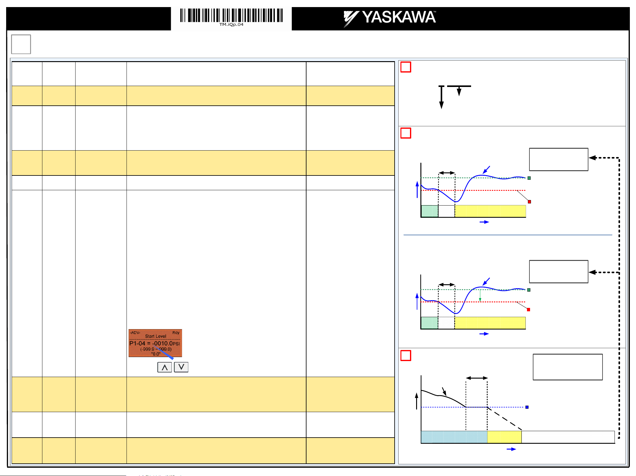
Programming the Start Level as an Absolute Value
Start Level has to programmed to a positive value in order for the Start Level to be an
absolute value. Example: Start Level P1-04 set to 50 PSI and delay time P1-05 set to
5 sec. Pump system will start when the pressure drops below 50 PSI for 5 sec.
Programming the Start Level as a Delta Level from the System Set-Point
Start Level has to programmed to a negative value in order for the Start Level to be a
delta value from the set-point.
Example: Start Level P1-04 set to –10 PSI with a system set-point of 50 PSI and a delay
time P1-05 set to 5 sec. Pump system will start when the pressure drops below 40 PSI
(50 - 10) for 5 sec.
For submersible motors use service
factor amps (SFA).
Confirm number of poles
2 Pole Motor = 3600 RPM
4 Pole Motor = 1800 RPM
6 Pole Motor = 1200 RPM
8 Pole Motor = 900 RPM
Confirm feedback device scaling.
(See Illustration 1)
Set to system pressure
It is mandatory to program the Start Level
in order to use the sleep function.
(See Illustration 2 and 3)
TRANSDUCER / FEEDBACK DEVICE SCALING
1
P1-03 = 0 0 0 0 0 Feedback Scaling
Examples:
Feedback
Maximum
Decimal Point
0 – 1000, no decimals, P1-03 = 1000
0 – 300.0, one decimal, P1-03 = 10300
0 – 50.00, two decimals, P1-03 = 25000
Position
START LEVEL
2
Example: Absolute Level (Positive Start Level)
SYSTEM STARTS WHEN
PRESSURE SIGNAL
FALLS BELOW 100 PSI
System Set-Point
(Example 150 PSI)
100 PSI
Start Level P1-04 (Absolute)
(Example 100 PSI)
Feedback Scaling (P1-03)
(Example 200 PSI)
200 PSI
150
Pressure
Start Level Delay (P1-05)
(Example 5.0 sec.)
Start
WAIT
0
Delay
Feedback Signal from
pressure transducer
(4 – 20 mA)
Start Pump System
Time
Example: Delta Level (Negative Start Level)
Note: When System Set-point is changed, the start level is automatically adjusted.
SYSTEM STARTS WHEN
PRESSURE SIGNAL
FALLS BELOW 100 PSI
System Set-Point
(Example 150 PSI)
100 PSI
Start Level P1-04 (Delta)
(Example -50 PSI,
Start Level = 150 – 50 = 100 PSI)
Feedback Scaling (P1-03)
(Example 200 PSI)
200 PSI
150
Pressure
Start Level Delay (P1-05)
(Example 5.0 sec.)
Start
WAIT
0
Delay
Feedback Signal from
pressure transducer
(4 – 20 mA)
-50 PSI
Start Pump System
Time
Page 2 of 4
P1-06 40.0 Hz
P4-10
P5-04
0
Disabled
1
Enabled
Minimum Pump
Frequency
Auto Mode Operator
Run Power Down
Storage
Hand Key
Enable / Disable
Use to change the sign.
Minimum speed (Hz) the pump motor has to operate at.
Example: Base pump motor speed is 3600 RPM, minimum speed is 2400 RPM. Set
minimum pump frequency to 40.0 Hz. (2400 ÷ 3600 x 60 Hz = 40 Hz)
Stores the run status in the Auto mode when operating from digital operator (b1-02=0).
0: Disabled
1: Enabled
Enables or disables the Hand Key on the digital operator.
0: Disabled
1: Enabled
Minimum pump frequency should be set to
a value where the pump enters a no-flow
condition.
Recommended for use when Start/Stop
command is from keypad.
(See Illustration 6)
Hand Key on keypad.
(See Illustration 4)
3
SLEEP MODE (Example)
60 Hz
Frequency
(pump motor
Output Frequency
0
Output
speed)
Sleep Delay Time (P2-03)
(Example 5.0 sec.)
Pump Running
Go to Sleep
Time
SYSTEM GOES TO SLEEP
WHEN PUMP MOTOR SPEED
DROPS BELOW 2400 RPM
Minimum Speed P1-06
(Example 40.0 Hz)
Ramp or Coast to Stop, b1-02
WAIT FOR PRESSURE TO FALL BELOW
START LEVEL (P1-04)
Page 3

iQpump 7 AC Drive (Software 0034)
Simplex Quick Start Procedure
Step
5
Page 3 of 4
iQpump Factory Defaults Overview (only adjust settings based on your application)
Parameter Value
b5-03 3.0 sec. PI Integral Time Decrease integral time to make iQpump more responsive.
2
b5-12
b5-14 2.0 sec. PI Feedback Loss Detection Time
C1-01 20.0 sec. Acceleration Time 1 Time it takes to accelerate the pump motor from zero to maximum speed.
C1-02 10.0 sec. Deceleration Time 1 Time it takes to decelerate the pump motor from maximum speed to zero.
L5-01 5 Number of Restart Attempts
L5-03 20 sec. Maximum Restart Time After Fault
P1-06 40.0 Hz Minimum Pump Frequency
(Fault)
PI Feedback Reference Missing
Detection Selection
Description
Reference
Select what to do when the feedback device (transducer) fails or gets disconnected.
0: Disabled, continue running no message is displayed
1: Alarm, show warning on the keypad when the feedback device fails or is disconnected
2: Fault, stop pump system when the feedback fails or is disconnected
Delay time before iQpump shows alarm or fault when feedback device has failed or is
disconnected. Example: 2.0 sec., iQpump displays alarm or fault 2 sec. after the device has
failed or is disconnected.
Determines the number of times iQpump will perform an automatic restart on the faults listed
in the comments column.
iQpump System Protection Faults that can be setup to restart are Low Level Feedback,
High Level Feedback, Transducer Loss, Not Maintaining Set-point, Loss of Prime,
Pump Over Cycle. Refer to parameters P4-07 and P4-08. The number of restart attempts is
set by L5-01.
If the restart fails (or is not attempted due to a continuing fault condition) iQpump waits the
Maximum Restart Time After Fault, before attempting another restart.
Minimum speed (Hz) the pump motor has to operate at.
Example: Base pump motor speed is 3600 RPM, minimum speed is 2400 RPM. Set minimum
pump frequency to 40.0 Hz. (2400 ÷ 3600 x 60 Hz = 40 Hz)
Comments
Caution: can cause instability if
value is too low.
NOTE: Disable parameter b5-12
if no transducer is installed.
Adjusted depending on system
performance
Overcurrent
Ground Fault
Output Phase Loss
Input Phase Loss
iQpump Overload
Motor Overload
Overtorque
DC Bus Fuse Blown
DC Bus Undervoltage
DC Bus Overvoltage
Overheat
P1-06 should be set to the level
where the pump can produce the
minimum pressure even at zero
flow.
HAND MODE OPERATION
4
Hand Speed from the Keypad/Digital Operator (Default)
Press the HAND KEY on the digital operator to run the system in Hand Mode.
Hand Mode speed can be adjusted by pressing , use
to move the cursor and to adjust the hand speed reference.
Press to save new active hand speed reference.
‘0’ Blinking
Hand Speed from Analog Input (0 – 10V)
Set parameter P5-01 ‘Hand Mode Ref.’ to ‘0’ to adjust the hand mode
reference from an external 0 – 10V signal connected to terminal A1 and AC.
SP A2 +V AC ACSC A1SN
S3 S5 S6 S7 FM AC AM IGS2 S4S1
+
0 – 10V
-
R+ R-
S+ S-
HAND KEY
Note: Hand Key can be disabled with parameter P5-04
THRUST BEARING - SUBMERSIBLE MOTORS (e.g. Franklin)
5
Note: Thrust Bearing Function is Enabled by Default
When using a submersible motor in combination with iQpump, it is recommended to use the Thrust Bearing
function to prevent excess motor wear. To enable this function, enter the minimum motor frequency in parameter
P4-05. Example: Minimum motor speed 1800 RPM, 1800 RPM ÷ 3600 RPM x 60.0 Hz = 30.0 Hz
Turn Off Thrust Bearing Function
(Output Frequency Reached)
Thrust Acceleration Time P4-04
(Example 1.0 sec.)
Thrust Bearing Frequency P4-05
(Example 30.0 Hz)
T
.
l
e
c
c
A
4
-0
4
Output Frequency
P
Thrust Bearing
C1-01 Acceleration Time
e
m
i
Output Frequency
Auto/Hand Operation
P2-03 5 sec. Sleep Delay Time
P4-05 30.0 Hz Thrust Bearing Frequency
P4-11 0.2 Min Utility Start Delay
Time it takes before the pump system goes to sleep when the selected signal level (P2-01)
falls below the specified sleep level (P2-02)
Sets the frequency reference used when the thrust bearing function is active. A value of 0
disables this function.
When utility power is restored and P4-10 is enabled (1), iQpump waits the time specified in
P4-11 before auto operation becomes active.
Adjust according to system
requirements.
Primarily used for submersible
pumps. Program P4-05 = 0.0 Hz
to disable function when iQpump
is used with a centrifugal pump.
Note: Only active when P4-10 is
enabled (1) and operation
(start/stop) is from the
digital operator.
Time
AUTO OPERATION – POWER DOWN STORAGE
6
Allows iQpump to automatically start after power failure when operated from keypad / digital operator. This function
is recommended for use when operating the iQpump in remote / unmanned areas.
When the iQpump is powered down while running, an internal run
command will automatically be initiated upon power-up.
Page 4

TYPICAL DISPLAY MESSAGES
Yaskawa Electric America, Inc.
2121 Norman Drive South
Waukegan, IL 60085
(800) YASKAWA (927-5292) / Fax (847) 887-7310
DrivesHelpDesk@
yaskawa.com
www.yaskawa.com
YEA Document Number: TM.iQp.04 5/08/2013
© 2009 Yaskawa Electric America, I
nc.
Sleep and Anti-No-Flow (ANF) Detection
NOTE:
Step 1:
Step 2:
Example:
Note:
Step 3:
Step 4:
Step 5:
iQpump 7 AC Drive (Software 0034)
Simplex Quick Start Procedure
Page 4 of 4
Step
Pump Rotation and Feedback Signal Check
6
When Pump Quick Setup is completed, press to exit the Pump Quick Setup
menu and go to operation.
In this step the pump motor is checked for proper direction and operation. This test is to
be performed solely from the digital operator. Apply power to the iQpump after all the
electrical connections have been made and the terminal cover has been reattached. At
this point, DO NOT RUN THE MOTOR, the digital operator should display as shown
below in Fig. 5.
FWD LED
ON
01 Flashing
Fig. 5 Digital Operator
Step
Auto Mode Operation
7
iQpump can be operated in automatic mode when the following actions have been
performed:
All parameters are programmed
Pump motor direction has been checked
Feedback signal has been checked
At this point, DO NOT RUN THE MOTOR, the digital operator should display as shown
below in Fig. 6.
FWD LED
ON
01 Flashing
Fig. 6 Digital Operator
(P2-23, P2-24, P2-25)
Before adjusting Anti-No-Flow operation ensure your system is regulating
satisfactory while operating under normal running conditions.
If stable continue to Step 1 to verify no-flow/sleep operation. If unstable turn off the
Anti-No-Flow function (P2-23 = 0.00%) and adjust the PI control parameters b5-02
and b5-03 to stabilize pump system. Refer to iQpump User Manual
(Document No. TM.iQp.06) for additional information. Once the system is stable,
re-enable the Anti-No-Flow function by setting P2-23 to 0.40% and continue to Step 1
to verify no-flow/sleep operation.
Verify system holds pressure by creating a no-flow situation (e.g. close off
discharge valve).
Press OFF button on the digital operator, wait 1 min. until system stabilizes
and verify system pressure feedback U1-91. If the pressure drops more than 3 PSI
(U1-91) adjust P2-25 to the actual delta pressure drop plus 1 PSI.
be 4 + 1 or 5 PSI. N
(P1-04). If not, the system pressure is not holding and this needs to be corrected, or
the pump system will continue to cycle on and off.
U1-99 “ANF Timer” and verify that the value is incrementing and resetting back to zero
continuously. If the value holds at 10 sec. (P2-24) increase P2-24 “Anti-No-Flow
Detection Time” by increments of 5 sec. Repeat Step 3 each time P2-24 is adjusted.
Set-point is 80 PSI, pressure feedback U1-91 shows 76 PSI, P2-25 should
This value should always be more than your start level
Run system in normal automatic operation with flow. Next check monitor
RUN LED OFF
Next, push
Hand reference speed can be adjusted by pressing , use to move cursor
and to adjust the value. Press to save changes.
The motor should now be operating at low speed in the correct direction of pump.
RUN
Push
OFF
If the direction is not correct, then power down the iQpump.
DANGER, LETHAL VOLTAGES ARE PRESENT- Before applying power to the
!
iQpump, ensure that the terminal cover is fastened and all wiring connections
are secure. After the power has been turned OFF, wait at least five minutes until
the charge indicator extinguishes completely before touching any wiring, circuit
boards or components.
Using Safety precaution, and referring to Fig.1 or 2, swap any two of the three output
leads to the pump motor (U/T1, V/T2 and W/T3). After the wiring change repeat
Step 6 and recheck motor direction.
on the digital operator; the display should read
HAND
LED should be ON.
on the digital operator; the display should read as in Fig. 3.
STOP LED ON
FEEDBACK SIGNAL CHECK
Verify feedback on display (show keypad) matches mechanical pressure gauge.
RUN LED OFF
STOP LED ON
SET SYSTEM SET-POINT
Next, press
parameter d1-01 System Set-point in the Pump Quick Setup Menu
Use
Next press
operation menu.
iQpump automatically starts in Auto Mode when the feedback signal level falls below
the programmed level in parameter P1-04 for the specified time in P1-05.
145 PSI
Start Level Delay (P1-05)
to access or modify the system set-point that was entered using
to select the digit and
to store set-point and press
(Example 5.0 sec.)
Next, press the AUTO
button to start the
iQpump.
Example: 80 PSI
Feedback signal from
pressure transducer
to change the system set-point.
to return to the main
(4 – 20 mA)
System Set-Point
(Example 80 PSI)
Create a no-flow situation (e.g. close discharge valve) and monitor that U1-99
“ANF Timer” increments and holds at P2-24 time (value set in Step 3). Once the
Anti-No-Flow timer expires the speed will reduce gradually until it reaches minimum
pump speed (P1-06) where it will hold for 5 sec. (P2-03) before going to sleep.
Run system in normal automatic operation and verify sleep and wake-up
operation until system performs satisfactory.
Displays when the iQpump is about to
start. The feedback level has fallen below
the Start Level (P1-04) and the start delay
timer is active. Once the Start Level Delay
Time (P1-05) expires the iQpump will start.
Displays when “Thrust Bearing” mode is
active. To enable, enter value in parameter
P4-05
Displays when the iQpump is in “sleep”
mode or when the iQpump is waiting for
the feedback level to drop below the Start
Level (P1-04).
The feedback level has risen above P1-09
level for the time specified in P1-10. High
feedback fault is active in Hand Mode,
Auto Mode, Pre-Charge and Thrust Mode
when the iQpump is running.
Refer to parameter P1-02 and P1-03, if the feedback
device scaling or system units are incorrect.
FEEDBACK SIGNAL LEVEL
Pressure
Start
WAIT
0
Refer to Illustration 2 on Page 2 of 4 for additional information on the Start Level Function.
Delay
Start Pump System
Start Level P1-04
 Loading...