

Page 1

iQpump1000 AC Drive
Intelligent Pump Controller
Quick Start Guide
Type: CIMR-PW
Models:
To properly use the product, read this manual thoroughly and retain
for easy reference, inspection, and maintenance. Ensure the end user
receives this manual.
200 V Class: 3/4 to 175 HP ND
400 V Class: 3/4 to 1000 HP ND
600 V Class: 2 to 250 HP ND
A
Receiving
Mechanical Installation
1
2
MANUAL NO. TOEP YAIP1W 01B
Electrical Installation
Start-Up Programming &
Operation
Troubleshooting
Periodic Inspection &
Maintenance
Peripheral Devices &
Options
Specifications
Parameter List
MEMOBUS/Modbus
Communications
Standards Compliance
3
4
5
6
7
A
B
C
D
Page 2

Page 3

Simple Setup Procedure
u
This procedure is a supplement to other documentation supplied with this equipment and guides the user in properly wiring
the iQpump and motor. It also shows the configuration for a simplex pump application.
WARNING! Read and adhere to all safety messages contained in this manual prior to performing this procedure. When installing the system
be sure to follow good wiring practices and all applicable codes. Ensure that the mounting of the various components are secure and that
the environment, such as extreme dampness, poor ventilation etc. will not cause system degradation. Please read this cheat sheet and
other documentation provided with the iQpump thoroughly before attempting any installation.
The setup procedure begins on the next page.
YASKAWA TOEP YAIP1W 01B YASKAWA AC Drive - iQpump1000 Quick Start Guide
3
Page 4

Step
1
iQpump Model
Identification and Mounting
To make sure you received the correct model, it is
essential to verify the iQpump nameplate with your order
and make sure the iQpump has the correct rating so it can
be used with your motor. Please check the nameplate
information as shown in the example below.
Check that the available power will meet the input
power requirements.
Ensure that the output power from the iQpump is
compatible with the motor requirements.
Mounting the iQpump
In the case of systems with more than one iQpump, follow
the above procedure for each iQpump and motor.
The mounting of the iQpump is extremely important
regarding environment and accessibility. Depending on your
system, there are various models available and the mounting
dimensions (footprint) may be different. Because the
mounting procedure is fairly extensive, it is beyond the scope
of this document; Refer to the iQpump1000
Quick Start Guide (Document No. TOEPYAIP1W01)
received with the iQpump, Section 2.2 Mechanical
Installation. Match the model that you received and follow
the procedure described in the manual to ensure a safe and
functional installation. In cases where the system has more
than one iQpump, refer to the proper clearances required for
adequate ventilation. Please pay particular attention to:
The clearances to be maintained around the enclosure
for adequate ventilation.
The environmental specifications such as avoiding
excessive dampness, extreme temperatures, chemical
exposure, corrosive areas, etc. to avoid damage to the
equipment and to maintain safety.
Removing and Attaching the Terminal Cover
Improper removal of the iQpump terminal cover as well as
front cover can cause extensive damage to the iQpump. To
avoid damage to these items, please pay particular attention
Open Chassis
NEMA 1
Drive Model
Number
Input Power
Rating
Output
Power
Rating
Serial
Number
UL File
Number
Drive Spec Number
Weight
Software
Version
Normal
Duty Amps
CIMR-PW2A0021FAA
CIMR-PW2A0021FAA
CC :
8000
6W3050 - 2 - 100
J0073D207410100
to the iQpump1000 Quick Start Guide TOEPYAIP1W01
Section 3.5 Removing and Attaching the Terminal Cover.
Connect Motor and
Line Power
Step
2
WARNING DO NOT CONNECT ANY OF THE
FOLLOWING TERMINALS TO EARTH GROUND
B1 B2
-
+1 +2 +3
NOT USED
Fig.1 & 2 below show the electrical connections for the input
power and motor terminals for various iQpump models. Select
the proper diagram for the model you are installing (see Step
1). WITH POWER OFF make the appropriate connections.
Make sure to follow good wiring practices and all
applicable codes. Ensure that the equipment is grounded
properly as shown in fig. 1
DANGER; LETHAL VOLTAGES ARE PRESENT - Before
applying power to the iQpump, ensure that the terminal
cover is fastened and all wiring connections are secure.
After the power has been turned OFF, wait at least five
minutes until the charge indicator extinguishes
completely before touching any wiring, circuit boards or
components.
!
Make sure the iQpump has been properly sized for single phase input
power. For best performance, the drive input supply voltage must be
equal to or greater than the motor rated voltage.
3Ø Induction
motor
Connect
frame to
ground
Input
Protection
(Fuse or Circuit
Breaker)
To change direction of motor
rotation swap any two of the
three motor leads.
Fig. 2 Input Power and Output Motor Electrical Connections for
Models: 2_0110 & Larger and 4_0058 & Larger
(R/L1) (S/L2)
(T/L3)
(U/T1)
(V/T2)
(W/T3)
Connect to
chassis
ground
Use L1, L2, L3 for
3Ø Input Power
L1
L2
L3
Use L1, L2 for
1Ø Input Power
*
BUS TERMINALS:
DO NOT CONNECT TO GROUND
Use L1, L2, L3 for
3Ø Input Power
To change
direction of
motor rotation
swap any two
of the three
motor leads.
Fig. 1 Input Power and Output Motor Electrical Connections for
Models: 2_0004 - 2_0056, 4_0002 - 4_0044 and 5_0003 - 50011
Use L1, L2 for
1Ø Input Power
3Ø Induction
motor
Connect
frame to
ground
Input
Protection
(Fuse or Circuit
Breaker)
L1
L2
L3
(R/L1)
(S/L2)
(T/L3)
(U/T1)
(V/T2)
(W/T3)
Connect to
chassis ground
*
DC Bus terminals
location varies by
model.
*
Step
3
Real-time
Clock Setup
This step shows how to setup the
iQpump real-time clock for first
use.
Note: If clock is not set the drive
can still be programmed and
operated, but ALM light will flash
every 30s and showing Clock
Not Set message.
Power up the drive and set the
real-time Clock. The real-time
Clock setup screen will appear at
first power up.
Press to set the clock.
Note: After the real-time clock is
set the real-time clock setup
screen will not show again unless
parameter o4-17 is set to “Set”.
Real-time Clock Setup Screen
Use to move cursor to
The left and to move
cursor to the right
use to adjust.
When date and time are set
press to save.
Note: Do NOT adjust sec per
month.
Example: Jun 12th 2012, 7:35am
4
YASKAWA TOEP YAIP1W 01B YASKAWA AC Drive - iQpump1000 Quick Start Guide
Page 5
Step
4
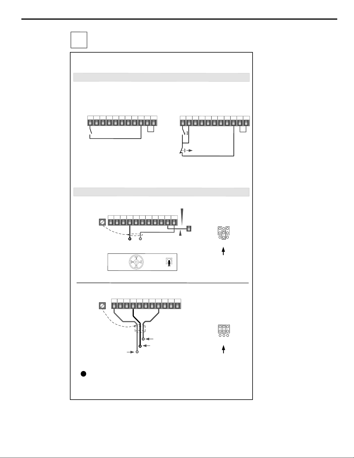
This step shows how to connect control wiring and feedback signal to the iQpump
.
Before
making any control connections
MAKE SURE POWER TO THE iQpump IS TURNED
OFF
!
Next remove the terminal cover to gain access to the control terminals
. (
Step
1
.)
SELECT START
/
STOP CONTROL METHOD
b
1
-
02
NOTE
:
It is beyond the scope of this document to program the iQpump drive for network communication control
.
Please refer to the refer to the iQpump1000 Quick Start Guide
(
Document No.
.
TOEPYAIP1W01)
for this selection.
.
FEEDBACK SIGNAL WIRING
(
TRANSDUCER
)
Wiring Diagram
:
2
-
Wire Control
Run
(
FWD
)
Wiring Diagram
:
3
-
Wire Control
Use for momentary contacts
Use for maintained contacts
User Terminals
User Terminals
Note
:
3
rd
row of terminal board is shown here
.
Link
Start
Switch
Stop
Switch
Normally
Open
Normally
Closed
Link
+
V
AC
A
1
A
2
A
3
FM
AM
AC
RP
AC
24
V
Brown or Red
: +
Power
(
1
)
Black
:
Output
4
–
20
mA
(
2
)
Cable
Shield
+
V
AC
A
1
A
2
A
3
FM
AM
AC
RP
AC
24
V
2
-
Wire
,
4
-
20
mA Transducer
Cable
Type
DIN
Type
E
(
G
)
S
1
S
2
S
3
S
4
S
5
S
6
S
7
S
8
SN
SC
SP
S
1
S
2
S
3
S
4
S
5
S
6
S
7
S
8
SN
SC
SP
Install link
(
AC
-
SN
)
when
using transducer
.
SN
Factory Installed
To use
3
-
Wire Control first Initialize the
iQpump using parameter A
1
-
03
=
3330
(
Refer to the Quick Start Guide
TOEP YAIP
1
W
01
)
For use with
3
-
Wire
,
0
–
10
V Transducer
Brown or Red
: +
Power
(
1
)
Black or White Output
0
–
10
V
(
3
)
Blue or Black Common Signal
(
2
)
Important Note
:
Signal colors and numbering may vary depending
on feedback device used
,
please consult feedback device manual
.
!
The iQpump is
DEFAULT SETUP TO START
/
STOP FROM THE KEYPAD
(
digital operator
).
If this is the preferred start
/
stop method then continue to the feedback signal connection
section
.
Please refer to the wiring diagram below to start
/
stop the iQpump using an external
switch or contact
.
For use with
2
-
Wire
,
4
–
20
mA Transducer
(
Factory Default
)
E
(
G
)
(
Factory Default
)
Jumper located
inside the drive on
the terminal board
Note
:
2
nd
row of terminal
board is shown here
.
A
1
A
3
A
2
V
I
Set Jumper to use
0
–
10
V
Transducer
Jumper located
inside the drive on
the terminal board
Note
:
2
nd
row of terminal
board is shown here
.
A
1
A
3
A
2
V
I
3
-
Wire
,
0
-
10
V Transducer
S
e
l
ec
t
i
n
g
S
t
a
r
t
/
S
t
o
p
a
n
d
S
p
e
e
d
M
e
t
h
o
d
YASKAWA TOEP YAIP1W 01B YASKAWA AC Drive - iQpump1000 Quick Start Guide
5
Page 6
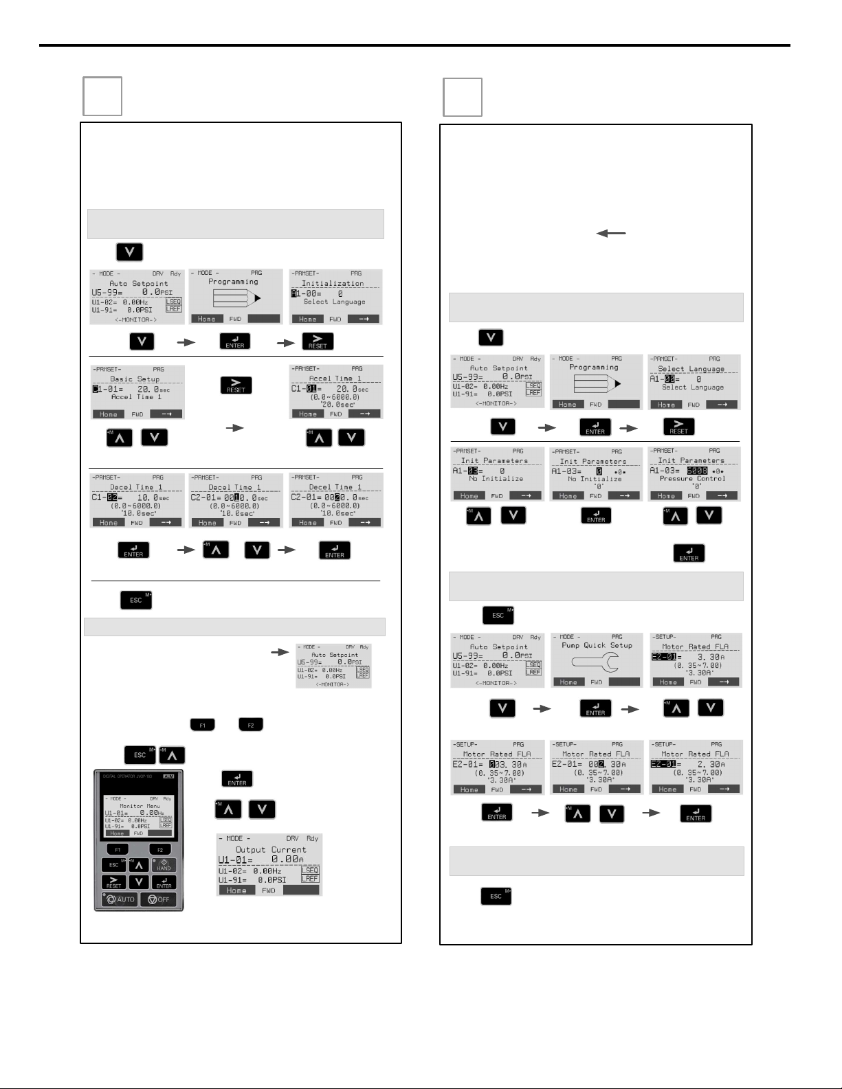
Step
5
Changing Parameters and
Monitoring the iQpump
This step shows how to access and modify an iQpump parameter
as well as how to monitor iQpump signals such as output
frequency and motor current.
Make sure all protective covers have been re-attached and power
is turned on. DO NOT RUN THE MOTOR.
Press two times until the digital operator shows the parameter menu.
Select Digit
Access Parameter Menu and Change Parameter Value
Monitor Motor Frequency and Motor Current
Please refer to the iQpump Quick Start Manual, (Document No.
TOEP YAIP1W 01) on how to access other drive monitors.
2X
Inc./Dec. Selection Inc./Dec. SelectionGo to Next Digit
Switch to Edit Mode Save New ValueModify Value
iQpump Digital Operator power-up state
Output Frequency and Transducer Feedback can be monitored
simultaneously.
Hold button for 3 sec. to go back to the main menu.
2X
Use and to select monitor signals.
Press simultaneously shows the monitor menu.
Use to select monitor.
Press to access monitor menu.
Step
6
Application Setup
This step shows how to configure the iQpump for a dedicated pump
application.
Make sure all protective covers have been re-attached and power is
turned on. DO NOT RUN THE MOTOR.
Available iQpump Application Macro’s:
6008 Constant Pressure Mode (PSI)
6009 Pump Down Level Mode (Ft)
6010 Geothermal Mode
6011 VTC Pressure Control Mode
7770 General Purpose Mode
Press two times until the digital operator shows the parameter menu.
Select Digit
Select Application
2X
Inc./Dec. Selection
Select Application
Switch to Edit Mode
Press to select.
Hold button for 3 sec. to go back to the main menu.
2X
Enter Application Parameters
3X
Select Parameter.
Switch to Edit Mode Save New ValueModify Value
Hold button for 3 sec. to go back to the main menu.
Go Back to Main Menu
Default
The factory default is setup for
constant pressure PSI, only
change if application different.
6
YASKAWA TOEP YAIP1W 01B YASKAWA AC Drive - iQpump1000 Quick Start Guide
Page 7
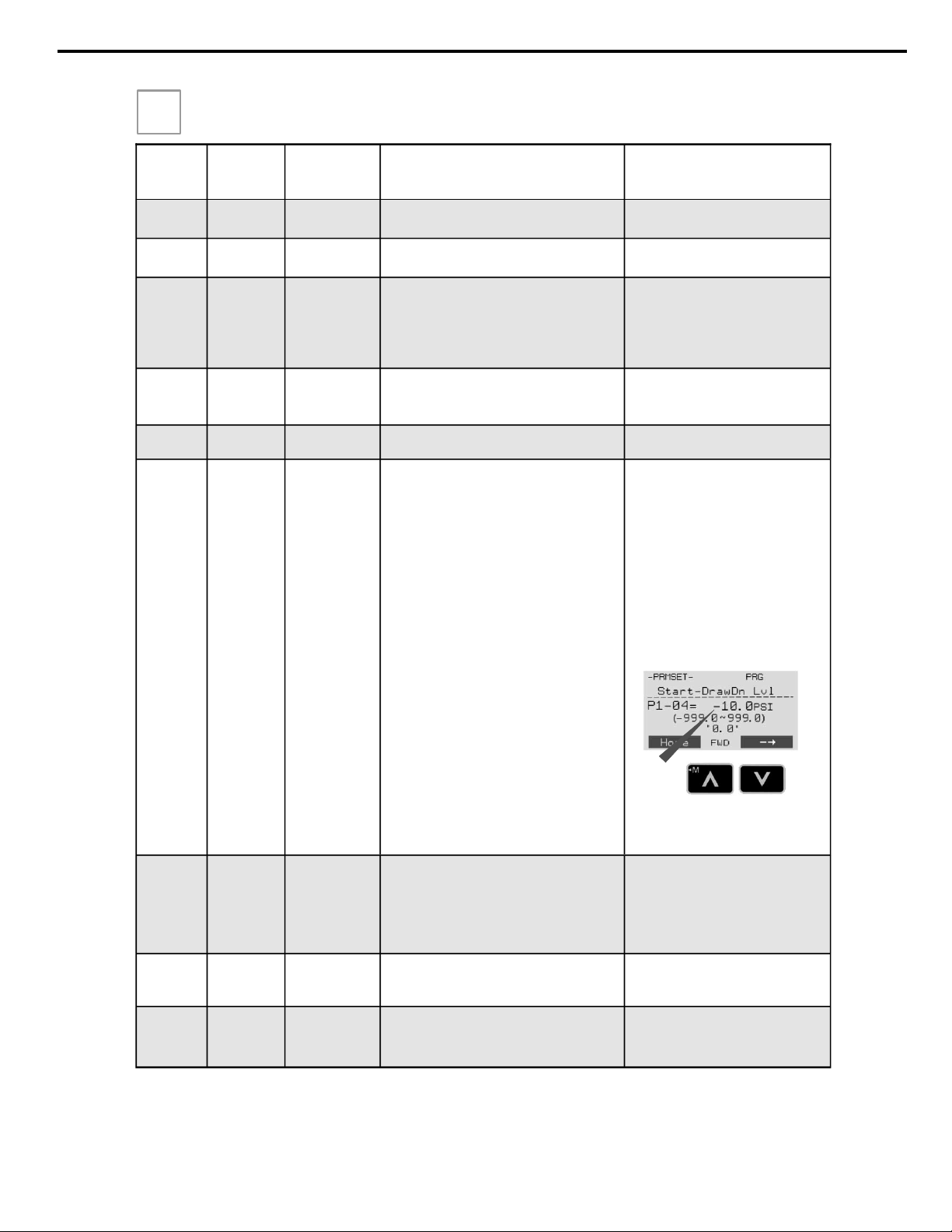
iQpump Quick Setup Parameter Overview (Simplex)
Step
7
Parameter Value Description Reference Comments
E2-01
Drive Size
Dependent
Motor Rated Current
Set to the motor nameplate full load amps.
For submersible motors use service
factor amps (SFA).
E2-04 2
Number of Motor
Poles
Number of motor poles is used to show the correct
motor RPM on the display
Enter ’4’ for an 1800 RPM motor and ‘2’ for a 3600
RPM motor.
Confirm number of poles
2 Pole Motor = 3600 RPM
4 Pole Motor = 1800 RPM
6 Pole Motor = 1200 RPM
8 Pole Motor = 900 RPM
P1-03 145
Feedback Device
Scaling
System Scaling: Enter feedback device maximum:
Example: Enter 200 for pressure transducer with a
maximum of 200 PSI at 20mA.
Confirm feedback device scaling.
(See Illustration 1)
Q1-01 0 Setpoint 1
Set System Setpoint Set to system pressure
P1-04 0.0 PSI
Start / Drawn
Down Level
When the iQpump is turned On and the feedback
signal level (transducer) falls below this level, the
pump system will start after the time specified in P1-
05 (default 1 sec).
Programming the Start Level as an Absolute
Value. Start / Draw Down Level has to programmed
to a positive value in order for the Start / Draw Down
Level to be an absolute value. Example: Start /
Draw Down Level P1-04 set to 50 PSI and delay
time P1-05 set to 5 sec. Pump system will start
when the pressure drops below 50 PSI for 5 sec.
Programming the Start Level as a Delta Level
from the System Setpoint
Start / Draw Down Level has to programmed to a
negative value in order for the Start Level to be a
delta value from the setpoint.
Example: Start / Draw Down Level P1-04 set to –10
PSI with a system setpoint of 50 PSI and a delay
time P1-05 set to 5 sec. Pump system will start
when the pressure drops below 40 PSI (50 - 10) for
5 sec.
It is mandatory to program the Start / Draw
Down Level in order to use the sleep func-
tion.
(See Illustration 2 and 3)
P1-06 40.0 Hz
Minimum Pump
Speed
Minimum speed (Hz) the pump motor has to operate
at. Example: Base pump motor speed is 3600 RPM,
minimum speed is 2400 RPM. Set
minimum pump frequency to 40.0 Hz. (2400 ÷ 3600
x 60 Hz = 40 Hz)
Minimum pump frequency should be set to
a value where the pump enters a no-flow
condition.
P4-10
0
Disabled
Auto Mode Operator Run Power
Down
Storage
Stores the run status in the Auto mode when operating from digital operator (b1-02=0).
0: Disabled
1: Enabled
Recommended for use when Start/Stop
command is from the keypad.
(See Step 9)
P5-04
1
Enabled
Hand Key
Enable / Disable
Enables or disables the Hand Key on the digital operator.
0: Disabled
1: Enabled
Hand Key on keypad.
(See Step 10)
A1-06
Dependent on
Initialization
Mode
Application
Selected
Displays selected applications, see Step 6. Read-only cannot be modified
Use
to change the sign.
YASKAWA TOEP YAIP1W 01B YASKAWA AC Drive - iQpump1000 Quick Start Guide
7
Page 8
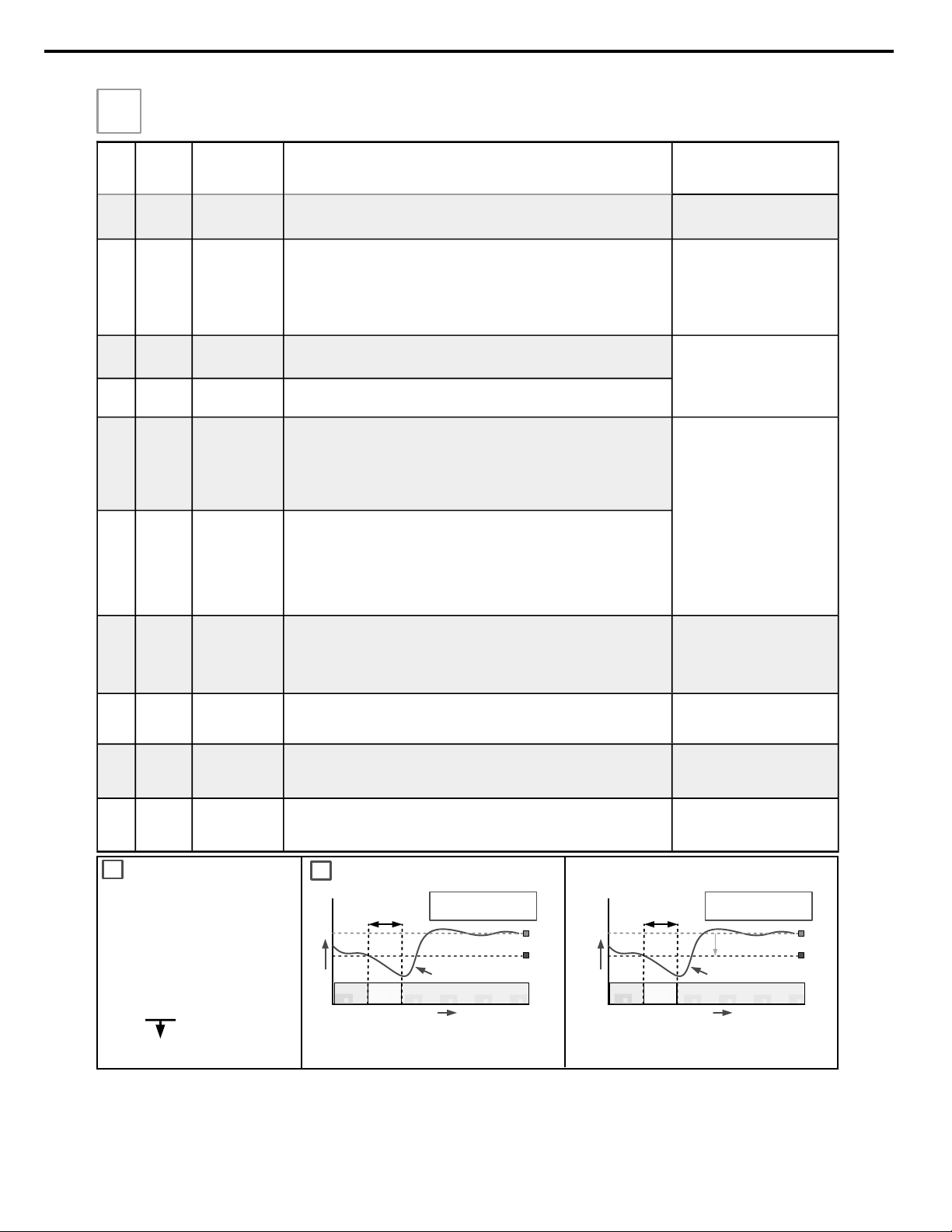
Step
7
No.
Value Description
Reference
Comments
b5-03 3.0 sec. PI Integral Time
Decrease integral time to make iQpump more responsive.
Caution: can cause instability if
value is too low.
b5-12
2
(Fault)
PI Feedback Reference Missing
Detection Selection
Select what to do when the feedback device (transducer) fails or gets disconnected.
0: Disabled, continue running no message is displayed
1: Alarm, show warning on the keypad when the feedback device fails or is discon-
nected
2: Fault, stop pump system when the feedback fails or is disconnected
NOTE: Disable parameter b5-12
if no transducer is installed.
C1-01
20.0 sec.
See Note
Acceleration Time
1
Time it takes to accelerate the pump motor from zero to maximum speed.
NOTE: Factory default with Thrust Mode enabled is 12.0 sec, 20.0 sec when disabled.
Adjusted depending on system
performance
C1-02
10.0 sec.
See Note
Deceleration
Time 1
Time it takes to decelerate the pump motor from maximum speed to zero.
NOTE: Factory default with Thrust Mode enabled is 5.0 sec, 10.0 sec when dis-
abled.
L5-01 5
Number of Restart Attempts
Determines the number of times iQpump will perform an automatic restart on the
faults listed in the comments column.
iQpump System Protection Faults that can be setup to restart are Low Level Feedback,
High Level Feedback, Transducer Loss, Not Maintaining Setpoint, Loss of Prime,
Pump Over Cycle. Refer to parameters P4-07 and P4-08. The number of restart attempts is set by L5-01.
Overcurrent
Ground Fault
Output Phase Loss
Input Phase Loss
iQpump Overload
Motor Overload
Overtorque
DC Bus Fuse Blown
DC Bus Undervoltage
DC Bus Overvoltage
Overheat
L5-03 20 sec.
Maximum Restart
Time After Fault
If the restart fails (or is not attempted due to a continuing fault condition) iQpump
waits the Maximum Restart Time After Fault, before attempting another restart.
P1-06 40.0 Hz
Minimum Pump
Frequency
Minimum speed (Hz) the pump motor has to operate at.
Example: Base pump motor speed is 3600 RPM, minimum speed is 2400 RPM. Set
minimum pump frequency to 40.0 Hz. (2400 ÷ 3600 x 60 Hz = 40 Hz)
P1-06 should be set to the level
where the pump can produce the
minimum pressure even at zero
flow.
P2-03 5 sec. Sleep Delay Time
Time it takes before the pump system goes to sleep when the selected signal level
(P2-01) falls below the specified sleep level (P2-02)
Adjust according to system
requirements.
P4-12 30.0 Hz
Thrust Bearing
Frequency
Sets the frequency reference used when the thrust bearing function is active. A
value of 0 disables this function.
Primarily used for submersible
pumps. Program P4-12 = 0.0 Hz
to disable function when iQpump is
used with a centrifugal pump.
P4-17 0.2 Min Utility Start Delay
When utility power is restored and P4-10 is enabled (1), iQpump waits the time
specified in P4-11 before auto operation becomes active.
Note: Only active when P4-10 is
enabled (1) and operation
(start/stop) is from the
digital operator.
iQpump Factory Defaults Overview
(adjust certain settings specific to the application)
P1-03 = 200.0 PSI Feedback Scaling
P1-02 Feedback Unit
0: Inch of Water 8: Bar
1: PSI 9: Pascal
2: GPM 10: Degrees Celsius
3: Degrees Fahrenheit 11: Meter
4: CFM 12: Feet
5: CMH 13: Liters per Minute
6: Liters / Hr 14: cm per Minute
7: Liters/Sec 15: Inch Hg
25: No Unit
Feedback
Maximum
SYSTEM FEEDBACK UNIT /
FEEDBACK DEVICE SCALING
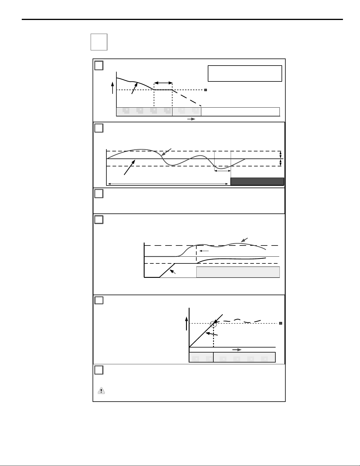
1
START / DRAW DOWN LEVEL
Start Pump System
Start
Delay
200
PSI
Start / Draw Down Level (P1-04)
(Example 100.0 PSI)
System Setpoint
(Example 150.0 PSI)
Feedback Signal from pressure
transducer (4 – 20 mA)
0
Time
Pressure
Start Level Delay (P1-05)
(Example 5.0 sec.)
System Units (P1-02)
(Example PSI)
Feedback Scaling (P1-03)
(Example 200.0 PSI)
WAIT
2
SYSTEM STARTS WHEN
PRESSURE SIGNAL FALLS
BELOW 100 PSI
Example: Absolute Level (Positive Start Level)
Example: Delta Level (Negative Start Level)
150
Start Pump System
Start
Delay
Start / Draw Down Level (P1-04)
(Example -50.0 PSI, (150.0 – 50.0)
System Setpoint
(Example 150.0 PSI)
Feedback Signal from pressure
transducer (4 – 20 mA)
Time
Pressure
Start Level Delay (P1-05)
(Example 5.0 sec.)
System Units (P1-02)
(Example PSI)
Feedback Scaling (P1-03)
(Example 200.0 PSI)
WAIT
SYSTEM STARTS WHEN
PRESSURE SIGNAL FALLS
BELOW 100 PSI
-50.0 PSI
150
200
PSI
START / DRAW DOWN LEVEL
8
YASKAWA TOEP YAIP1W 01B YASKAWA AC Drive - iQpump1000 Quick Start Guide
Page 9
Step
7
iQpump Factory Defaults Overview
(adjust certain settings specific to the application)
THRUST BEARING - SUBMERSIBLE MOTORS
When using a submersible motor in combination
with the iQpump, it is recommended to use the
Thrust Bearing function to prevent excess motor
wear. To enable this function , enter the minimum
motor frequency in parameter
P4-11. Example: Minimum motor speed 1800
RPM, 1800 RPM ÷ 3600 RPM x 60.0 Hz = 30.0 Hz
Output Frequency
Output Frequency
Thrust Bearing Frequency P4-12
(Example 30.0 Hz)
Time
Thrust
Bearing
Auto/Hand Operation
Turn Off Thrust Bearing Function
(Output Frequency Reached)
P
4
-
04
Accel
.
Time
Thrust Acceleration Time P4-11
(Example 1.0 sec.)
C1-01 Acceleration Time
PUMP SYSTEM FAULT SETUP
PRE-CHARGE OPERATION
5
4
6
7
LOW/HIGH FEEDBACK LEVEL DETECTION
AUTO OPERATION – POWER DOWN STORAGE
8
Allows iQpump to automatically start after power failure when operated from keypad / digital operator. This function is
recommended for use when operating the iQpump in remote / unmanned areas. Use parameter P4-10 to enable.
When the iQpump is powered down while running , an internal run
command will automatically be initiated upon power -up.
This function is used when the pump system requires to be pre-charged before normal operation. Upon start the
iQpump will run at a fixed speed for a specified time or until the feedback signal reaches a programmed level after
which it will switch to auto mode operation.
Feedback
0 Hz
Pre-Charge Freq. P4-02
Pre-Charge Completed
Pre-Charge Lvl. P4-01
P4-01 Pre-Charge Level: Specified feedback level to stop pre-charge operation
P4-02 Pre-Charge Frequency: Set desired pre-charge speed
P4-03 Pre-Charge Time: Specified maximum pre-charge operation time
FEEDBACK SIGNAL
P1-11
Time
SETPOINT
SET-POINT NOT MET
P1-16
Setpoint -LOP Tim
The iQpump can display a ‘Setpoint Not Met’ fault when the iQpump is unable to maintain the programmed system
setpoint due a problem with the pump system. Set P1-15 to the maximum allowed difference between setpoint and
feedback level.
P1-11
P1-15 Max Setpoint Diff
iQpump continuously monitors the system feedback signal. To display a ‘ Low Feedback’ fault set the low feedback
level parameter P1-08 to the minimum feedback level allowed for your system and to display a ‘High Feedback’
fault set the high feedback level parameter P1-11 to the maximum feedback level allowed.
Auto Operation
Output
Frequency
SLEEP MODE (Example)
Minimum Speed P1-06
(Example 40.0 Hz)
Output Frequency
(pump motor speed)
0
Sleep Delay Time (P2-03)
(Example 5.0 sec.)
Ramp or Coast to Stop, b1-02
Output Frequency
60 Hz
Pump Running
Go to Sleep
Time
WAIT FOR PRESSURE TO FALL BELOW
START / DRAW DOWN LEVEL (P1-04)
SYSTEM GOES TO SLEEP WHEN
PUMP MOTOR SPEED DROPS BELOW
40 Hz (2400 RPM for 3600 RPM Motor).
3
YASKAWA TOEP YAIP1W 01B YASKAWA AC Drive - iQpump1000 Quick Start Guide
9
Page 10
Motor Rotation Test
In this step the motor is checked for proper direction and operation. This
test is to be performed solely from the digital operator. Apply power to the
iQpump after all the electrical connections have been made and protective
covers have been re-attached. At this point, DO NOT RUN THE MOTOR,
the Digital Operator should display as shown in Fig. 3.
Fig. 3: Digital Operator
Use precaution, and refer to
Fig.1 or 2, swap any two of the
three output leads to the motor
(U/T1, V/T2 and W/T3). After the
wiring change, repeat Step 8
and recheck motor direction.
After the power has been turned OFF, wait at least five minutes until
the charge indicator extinguishes completely before touching any
wiring, circuit boards or components.
DANGER
!
Digital Operator
turned off.
Verify feedback on display (show keypad) matches mechanical pressure
gauge.
FEEDBACK SIGNAL CHECK
FEEDBACK SIGNAL LEVEL
Refer to parameter P1-02 and P1-03, if the
feedback device scaling or system units are
incorrect.
Next, push
and the
HAND
LED should be ON.
The motor should now be operating at in the correct direction of pump.
Push
on the Digital Operator; the display should read
on the Digital Operator; the display should read as in Fig. 3.
No alarm active
Auto Mode Off
Hand Mode Off
If the direction is not correct, then power down the iQpump and follow
Instructions below.
Press to access Hand Speed. Use to change
Hand Speed value. Press to save value.
Step
8
Pump Rotation and Feedback Signal Check
Step
9
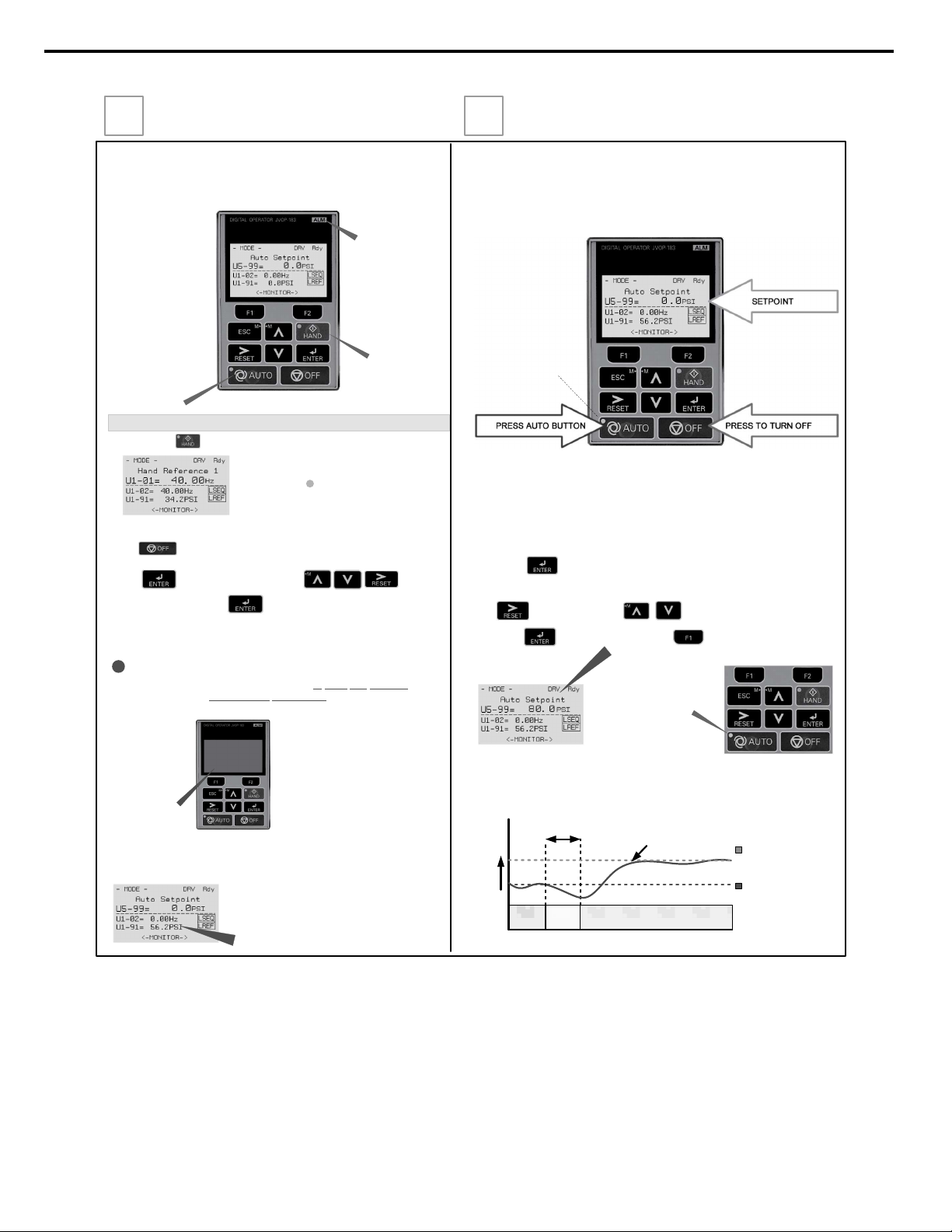
Auto Mode Operation
AUTO MODE
Press the AUTO button to put the iQpump into AUTO mode.
In AUTO mode the iQpump is capable of starting or stopping based on the Run Source
Selection setting parameter b1-02. (See Step 3 Select Start/Stop Control Method) The
setpoint used in AUTO mode is based on the Reference Source Selection setting
parameter b1-01. (See Step 3 Select Speed Method)
The iQpump can be operated in AUTO mode when the following actions have been
performed:
All parameters are programmed
Motor direction has been checked
Auto Mode: Reference source selected in parameter b1-01 (See step 3)
Auto Mode: Run source selected in parameter b1-02 (See Step 3)
Next, press
to access or modify the system setpoint that was entered using
SET SYSTEM SETPOINT
iQpump automatically starts in Auto Mode when the feedback signal level falls below
the programmed level in parameter P1-04 for the specified time in P1-05.
Use
to select the digit and
to change the system setpoint.
Next press
Next, press the AUTO
button to start the
iQpump.
Start Pump System
Start
Delay
145 PSI
Start / Draw Down
Level P1-04
System Setpoint
(Example 80 PSI)
Feedback signal from
pressure transducer
(4 – 20 mA)
0
Pressure
Start Level Delay (P1-05)
(Example 5.0 sec.)
WAIT
to store setpoint and press
operation menu.
to return to the main
Refer to Illustration 2 on Page 3 of 4 for additional information on the Start Level Function.
parameter Q1-01 System Setpoint in the iQpump Quick Setup Menu
Example: 80 PSI
LED is blinking
when AUTO mode
is active but AUTO
Run Command is
not active.
Fig. 4: Digital Operator
10
YASKAWA TOEP YAIP1W 01B YASKAWA AC Drive - iQpump1000 Quick Start Guide
Page 11
Sleep and Anti-No-Flow (ANF) Detection
NOTE: Before adjusting Anti-No-Flow operation ensure your system is regulating satisfactory while operating
under normal running conditions.
If stable continue to Step 1 to verify no-flow/sleep operation. If unstable turn off the Anti-No-Flow function
(P2-23 = 0.00%) and adjust the PI control parameters b5-02 and b5-03 to stabilize pump system. Refer to iQpump
Quick Start Guide (Document No.TOEP YAIP1W 01) for additional information. Once the system is stable, reenable the Anti-No-Flow function by setting P2-23 to 0.40% and continue to Step 1 to verify no-flow/sleep
operation.
Step 1: Verify system holds pressure by creating a no-flow situation (e.g. close off discharge valve).
Step 2: Press OFF button on the digital operator, wait 1 min. until system stabilizes and verify system pressure
feedback U1-91. If the pressure drops more than 3 PSI (U1-91) adjust P2-25 to the actual delta pressure drop plus
1 PSI.
Example: Setpoint is 80 PSI, pressure feedback U1-91 shows 76 PSI, P2-25 should be 4 + 1 or 5 PSI.
Note: This value should always be more than your start level (P1-04). If not, the system pressure is not holding
and this needs to be corrected, or the pump system will continue to cycle on and off.
Step 3: Run system in normal automatic operation with flow. Next check monitor
U1-99 “ANF Timer” and verify that the value is incrementing and resetting back to zero continuously. If the value
holds at 10 sec. (P2-24) increase P2-24 “Anti-No-Flow Detection Time” by increments of 5 sec. Repeat Step 3
each time P2-24 is adjusted.
Step 4: Create a no-flow situation (e.g. close discharge valve) and monitor that U1-99 “ANF Timer” increments and
holds at P2-24 time (value set in Step 3). Once the Anti-No-Flow timer expires the speed will reduce gradually until
it reaches minimum pump speed (P1-06) where it will hold for 5 sec. (P2-03) before going to sleep.
Step 5: Run system in normal automatic operation and verify sleep and wake-up operation until system performs
satisfactory.
(P2-23, P2-24, P2-25)
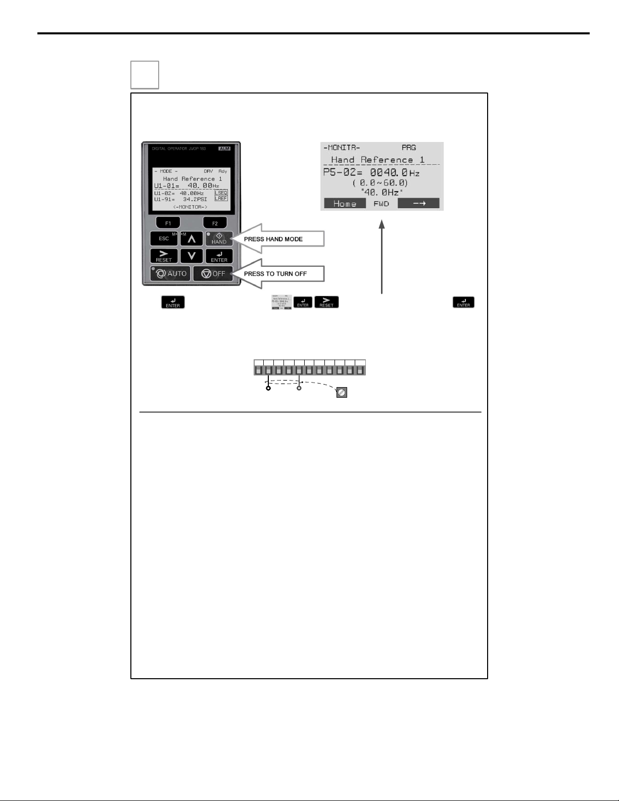
The iQpump can be operated in HAND mode when the following actions have been performed:
All parameters are programmed
Motor direction has been checked
HAND MODE
Press to access Hand Speed. Use to change Hand Speed value. Press
to save value.
Set parameter P5-01 ‘Hand Mode Ref.’ to ‘0’ to adjust the hand mode reference from an external 0 – 10V signal
connected to terminal A1 and AC.
Hand Speed from Analog Input (0 – 10V)
+
0 – 10V Connection
0 ~ 10 Vdc
+V AC A1 A2 A3 FM AM AC RP AC
24V
Cable
Shield
E(G)
Step
10
Hand Mode Operation
YASKAWA TOEP YAIP1W 01B YASKAWA AC Drive - iQpump1000 Quick Start Guide
11
Page 12

This Page Intentionally Blank
12
YASKAWA TOEP YAIP1W 01B YASKAWA AC Drive - iQpump1000 Quick Start Guide
Page 13

Table of Contents
SIMPLE SETUP PROCEDURE........................................................................ 3
i. PREFACE & GENERAL SAFETY.................................................................. 21
i.1 Preface ....................................................................................................................... 22
Applicable Documentation....................................................................................................... 22
Symbols................................................................................................................................... 22
Terms and Abbreviations ........................................................................................................ 22
Trademarks ............................................................................................................................. 22
i.2 General Safety ........................................................................................................... 24
Supplemental Safety Information ............................................................................................ 24
Safety Messages..................................................................................................................... 25
General Application Precautions ............................................................................................. 26
Motor Application Precautions................................................................................................. 28
Drive Label Warning Example................................................................................................. 30
Warranty Information............................................................................................................... 30
1. RECEIVING .................................................................................................... 31
1.1 Model Number and Nameplate Check ..................................................................... 32
Nameplate ............................................................................................................................... 32
2. MECHANICAL INSTALLATION..................................................................... 35
2.1 Mechanical Installation ............................................................................................. 36
Installation Environment .......................................................................................................... 36
Installation Orientation and Spacing........................................................................................ 36
Instructions on Installation Using the Eye Bolts ...................................................................... 38
HOA Keypad Remote Usage .................................................................................................. 40
Exterior and Mounting Dimensions ......................................................................................... 43
2.2 Flange Type Enclosure (NEMA 12 Backside) Dimensions & Heat Loss .............. 53
Flange Type Models 2A0004 to 2A0012, 4A0002 to 4A0005, and 5A0003 and 5A0004 ....... 53
Flange Type Models 2A0018 and 2A0021, 4A0007 to 4A0011, and 5A0006 and 5A0009 .... 57
Flange Type Models 2A0030 and 2A0040, 4A0018 and 4A0023, and 5A0011...................... 61
Flange Type Model 4A0031 .................................................................................................... 65
Flange Type Models 2A0056, 4A0038, and 5A0017 and 5A0022 .......................................... 68
Flange Type Models 2A0069 and 2A0081, 4A0044, and 5A0027 and 5A0032...................... 72
Flange Type Models 2A0110 and 4o0058 ............................................................................. 77
Flange Type Models 2A0138, 4o0072, and 5A0041 and 5A0052 ......................................... 81
Flange Type Models 4o0088 and 4o0103 ............................................................................ 86
Flange Type Models 2A0169 and 2A0211, 4o0139 and 4o0165, and 5A0062 to 5A0099... 90
YASKAWA
TOEP YAIP1W 01B YASKAWA AC Drive - iQpump1000 Quick Start Guide
13
Page 14

Table of Contents
Flange Type Models 2A0250 and 2A0312, 4o0208, and 5A0125 and 5A0145 ............................... 95
Flange Type Models 2A0360 and 2A0415, 4o0250 to 4o0362, and 5A0192 and 5A0242........... 101
Flange Type Model 4A0414 ............................................................................................................ 107
Flange Type Models 4A0515 and 4A0675 ...................................................................................... 110
Flange Type Models 4A0930 and 4A1200 ...................................................................................... 113
3. ELECTRICAL INSTALLATION ............................................................................ 117
3.1 Standard Connection Diagram.........................................................................................118
3.2 Main Circuit Connection Diagram....................................................................................121
Three-Phase 200 V Class Models 2A0004 to 2A0081
Three-Phase 400 V Class Models 4A0002 to 4A0044
Three-Phase 600 V Class Models 5A0003 to 5A0032 .................................................................. 121
Three-Phase 200 V Class Models 2A0110, 2A0138
Three-Phase 400 V Class Models 4A0058, 4A0072
Three-Phase 600 V Class Models 5A0041, 5A0052 ..................................................................... 121
Three-Phase 200 V Class Models 2A0169 to 2A0211
Three-Phase 400 V Class Models 4A0088 to 4A0139
Three-Phase 600 V Class Models 5A0062 to 5A0099 .................................................................. 122
Three-Phase 200 V Class Models 2A0250 to 2A0415
Three-Phase 400 V Class Models 4A0165 to 4A0675
Three-Phase 600 V Class Models 5A0125 to 5A0242 .................................................................. 122
Three-Phase 400 V Class Models 4A0930, 4A1200....................................................................... 123
Single-Phase Connections .............................................................................................................. 123
12-Phase Rectification .................................................................................................................... 123
3.3 Terminal Cover ..................................................................................................................125
Models 2A0004 to 2A0081, 4A0002 to 4A0044, 5A0003 to 5A0032 (IP20/NEMA Type 1
Enclosure)...................................................................................................................................... 125
Models 2A0110 to 2A0250, 4A0208 to 4A1200, and 5A0125 to 5A0242 (IP00/Open Type
Enclosure)...................................................................................................................................... 126
3.4 HOA Keypad and Front Cover..........................................................................................127
Removing/Reattaching the HOA Keypad ........................................................................................ 127
Removing/Reattaching the Front Cover .......................................................................................... 127
3.5 Top Protective Cover ........................................................................................................130
Removing the Top Protective Cover ............................................................................................... 130
Reattaching the Top Protective Cover ............................................................................................ 130
3.6 Main Circuit Wiring............................................................................................................131
Factory Recommended Branch Circuit Protection .......................................................................... 131
Main Circuit Terminal Functions...................................................................................................... 131
Protecting Main Circuit Terminals ................................................................................................... 133
Main Circuit Wire Gauges and Tightening Torque .......................................................................... 134
Main Circuit Terminal and Motor Wiring .......................................................................................... 141
3.7 Control Circuit Wiring .......................................................................................................143
Control Circuit Terminal Block Functions ........................................................................................ 143
Terminal Configuration .................................................................................................................... 145
Wiring the Control Circuit Terminal ................................................................................................. 146
3.8 Control I/O Connections ...................................................................................................148
Sinking/Sourcing Mode for Digital Inputs ........................................................................................ 148
Terminals A1, A2, and A3 Input Signal Selection............................................................................ 149
Terminal AM/FM Signal Selection ................................................................................................... 152
3.9 Connect to a PC.................................................................................................................153
14
YASKAWA TOEP YAIP1W 01B YASKAWA AC Drive - iQpump1000 Quick Start Guide
Page 15

Table of Contents
4. START-UP PROGRAMMING & OPERATION..................................................... 155
4.1 Drive Start-Up Preparation ...............................................................................................156
Start-Up Checklist ........................................................................................................................... 156
4.2 Powering Up the Drive ......................................................................................................158
Setting the Real Time Clock............................................................................................................ 158
4.3 Using the HOA Keypad .....................................................................................................162
Keys and Displays........................................................................................................................... 162
LCD Display .................................................................................................................................... 163
ALARM (ALM) LED Displays........................................................................................................... 164
AUTO LED and HAND LED Indications .......................................................................................... 164
Menu Structure for HOA Keypad..................................................................................................... 166
Changing Parameter Settings or Values ......................................................................................... 167
4.4 Pump Application Presets................................................................................................169
Parameters Set Depending on A1-03 Setting ................................................................................. 169
Parameters Displayed Depending on A1-06 Setting....................................................................... 170
4.5 iQpump Presets and Functions .......................................................................................171
iQpump Presets............................................................................................................................... 171
iQpump Functions ........................................................................................................................... 184
4.6 Basic iQpump Setup and Application Preset Parameters.............................................207
4.7 Test Run with No Load......................................................................................................236
No-Load Operation Test Run .......................................................................................................... 236
4.8 Test Run with Load Connected........................................................................................237
Test Run with the Load Connected ................................................................................................. 237
5. TROUBLESHOOTING.......................................................................................... 239
5.1 Drive Alarms, Faults, Errors, and Messages ..................................................................240
Types of Alarms, Faults, and Errors................................................................................................ 240
5.2 Fault Detection ..................................................................................................................241
Fault Displays, Causes, and Possible Solutions ............................................................................. 241
5.3 Alarm Detection.................................................................................................................260
Alarm Codes, Causes, and Possible Solutions ............................................................................... 260
5.4 Operator Programming Errors .........................................................................................274
Operator Programming Error Codes, Causes, and Possible Solutions........................................... 274
5.5 Auto-Tuning Fault Detection ............................................................................................278
Auto-Tuning Codes, Causes, and Possible Solutions..................................................................... 278
5.6 Copy Function Related Displays .....................................................................................281
Tasks, Errors, and Troubleshooting ................................................................................................ 281
5.7 HOA Keypad Display Messages ......................................................................................283
Fault Reset Methods ....................................................................................................................... 284
5.8 Auto-Tuning .......................................................................................................................285
Types of Auto-Tuning ...................................................................................................................... 285
Auto-Tuning Interruption and Fault Codes ...................................................................................... 286
Auto-Tuning Operation Example ..................................................................................................... 286
6. PERIODIC INSPECTION & MAINTENANCE ...................................................... 289
6.1 Inspection ..........................................................................................................................290
YASKAWA TOEP YAIP1W 01B YASKAWA AC Drive - iQpump1000 Quick Start Guide
15
Page 16

Table of Contents
Recommended Periodic Inspection................................................................................................. 290
6.2 Periodic Maintenance .......................................................................................................292
Replacement Parts.......................................................................................................................... 292
6.3 Drive Replacement ............................................................................................................294
Replacing the Drive ......................................................................................................................... 294
7. PERIPHERAL DEVICES & OPTIONS ................................................................. 297
7.1 Option Card Installation....................................................................................................298
Prior to Installing the Option ............................................................................................................ 298
Communication Option Installation Example................................................................................... 299
A. SPECIFICATIONS ................................................................................................ 303
A.1 Power Ratings ...................................................................................................................304
Three-Phase 200 V Class Drive Models 2A0004 to 2A0030 .......................................................... 304
Three-Phase 200 V Class Drive Models 2A0040 to 2A0211 .......................................................... 305
Three-Phase 200 V Class Drive Models 2A0250 to 2A0415 .......................................................... 306
Three-Phase 400 V Class Drive Models 4A0002 to 4A0031 .......................................................... 307
Three-Phase 400 V Class Drive Models 4A0038 to 4A0165 .......................................................... 308
Three-Phase 400 V Class Drive Models 4A0208 to 4A1200 .......................................................... 309
Three-Phase 600 V Class Drive Models 5A0003 to 5A0032 .......................................................... 310
Three-Phase 600 V Class Drive Models 5A0041 to 5A0099 .......................................................... 311
Three-Phase 600 V Class Drive Models 5A0125 to 5A0242 .......................................................... 312
A.2 Drive Specifications ..........................................................................................................313
A.3 Drive Watt Loss Data ........................................................................................................315
A.4 Drive Derating Data ...........................................................................................................317
Single-Phase Derating .................................................................................................................... 317
Temperature Derating ..................................................................................................................... 322
Altitude Derating.............................................................................................................................. 323
B. PARAMETER LIST............................................................................................... 325
B.1 A: Initialization Parameters ..............................................................................................326
A1: Initialization ............................................................................................................................... 326
A2: User Parameters....................................................................................................................... 327
B.2 b: Application.....................................................................................................................328
b1: Operation Mode Selection......................................................................................................... 328
b2: DC Injection Braking and Short Circuit Braking......................................................................... 329
b3: Speed Search............................................................................................................................ 329
b4: Timer Function .......................................................................................................................... 330
b5: PID Control................................................................................................................................ 330
b6: Dwell Function........................................................................................................................... 333
b8: Energy Saving ........................................................................................................................... 333
B.3 C: Tuning............................................................................................................................334
C1: Acceleration and Deceleration Times ....................................................................................... 334
C2: S-Curve Characteristics............................................................................................................ 334
C3: Slip Compensation.................................................................................................................... 335
C4: Torque Compensation .............................................................................................................. 335
C6: Carrier Frequency..................................................................................................................... 336
B.4 d: References.....................................................................................................................337
d1: Frequency Reference................................................................................................................ 337
16
YASKAWA TOEP YAIP1W 01B YASKAWA AC Drive - iQpump1000 Quick Start Guide
Page 17

Table of Contents
d2: Frequency Upper/Lower Limits ................................................................................................. 338
d3: Jump Frequency........................................................................................................................ 338
d4: Frequency Reference Hold and Up/Down 2 Function............................................................... 339
B.5 E: Motor Parameters .........................................................................................................340
E1: V/f Pattern ................................................................................................................................. 340
E2: Motor 1 Parameters .................................................................................................................. 341
B.6 F: Options...........................................................................................................................343
F4: Analog Monitor Card (AO-A3) ................................................................................................... 343
F5: Digital Output Card (DO-A3) ..................................................................................................... 343
F6, F7: Communication Option Card............................................................................................... 344
B.7 H Parameters: Multi-Function Terminals ........................................................................347
H1: Multi-Function Digital Inputs ..................................................................................................... 347
H2: Multi-Function Digital Outputs................................................................................................... 352
H3: Multi-Function Analog Inputs .................................................................................................... 355
H4: Analog Outputs ......................................................................................................................... 357
H5: MEMOBUS/Modbus Serial Communication ............................................................................. 358
H6: Pulse Train Input....................................................................................................................... 359
B.8 L: Protection Function ......................................................................................................360
L1: Motor Protection ........................................................................................................................ 360
L2: Momentary Power Loss Ride-Thru............................................................................................ 361
L3: Stall Prevention ......................................................................................................................... 362
L4: Speed Detection........................................................................................................................ 363
L5: Fault Restart.............................................................................................................................. 364
L6: Torque Detection....................................................................................................................... 365
L7: Torque Limit .............................................................................................................................. 366
L8: Drive Protection......................................................................................................................... 366
B.9 n: Special Adjustment.......................................................................................................368
n1: Hunting Prevention.................................................................................................................... 368
n2: Speed Feedback Detection Control (AFR) Tuning.................................................................... 368
n3: High Slip Braking (HSB) and Overexcitation Braking................................................................ 368
n6: Online Tuning ............................................................................................................................ 369
B.10 o: Operator-Related Settings ...........................................................................................370
o1: HOA Keypad Display Selection................................................................................................. 370
o2: HOA Keypad Keypad Functions................................................................................................ 371
o3: Copy Function ........................................................................................................................... 372
o4: Maintenance Monitor Settings................................................................................................... 372
B.11 P: Pump Parameters .........................................................................................................373
P1: Pump Basic............................................................................................................................... 373
P2: Pump Protection ....................................................................................................................... 375
P3: Contactor Multiplexing .............................................................................................................. 377
P4: Pump Advanced........................................................................................................................ 379
P5: Pump HAND Mode ................................................................................................................... 381
P6: Flow Meter Setup...................................................................................................................... 382
P7: Anti-Jam.................................................................................................................................... 384
P8: De-Scale / De-Ragging ............................................................................................................. 385
P9: Network Options ....................................................................................................................... 385
B.12 Q: PID Controller Parameters...........................................................................................390
Q1: Preset Setpoint ......................................................................................................................... 390
Q2: Geothermal Mode Setup .......................................................................................................... 390
Q3: Output Current Limit ................................................................................................................. 391
YASKAWA TOEP YAIP1W 01B YASKAWA AC Drive - iQpump1000 Quick Start Guide
17
Page 18

Table of Contents
Q4: Water Level Control.................................................................................................................. 391
Q5: Suction Pressure Control.......................................................................................................... 392
B.13 S: Special Application.......................................................................................................395
S1: Dynamic Noise Control Function .............................................................................................. 395
S2: Programmable Run Timers....................................................................................................... 395
S3: Secondary PI (PI2) Control ....................................................................................................... 397
S6: Protection.................................................................................................................................. 399
B.14 T: Motor Tuning .................................................................................................................400
T1: Induction Motor Auto-Tuning..................................................................................................... 400
B.15 U: Monitors.........................................................................................................................401
U1: Operation Status Monitors ........................................................................................................ 401
U2: Fault Trace................................................................................................................................ 404
U3: Fault History.............................................................................................................................. 405
U4: Maintenance Monitors .............................................................................................................. 406
U5: PID Monitors ............................................................................................................................. 409
U6: Operation Status Monitors ........................................................................................................ 410
U7: CASE Monitors ......................................................................................................................... 410
U9: Operation Status Monitors ........................................................................................................ 410
C. MEMOBUS/MODBUS COMMUNICATIONS........................................................ 411
C.1 MEMOBUS/Modbus Configuration ..................................................................................412
C.2 Communication Specifications ........................................................................................413
C.3 Connecting to a Network ..................................................................................................414
Network Cable Connection.............................................................................................................. 414
Wiring Diagram for Multiple Connections ........................................................................................ 415
Network Termination ....................................................................................................................... 416
C.4 MEMOBUS/Modbus Setup Parameters ...........................................................................417
MEMOBUS/Modbus Serial Communication.................................................................................... 417
C.5 Drive Operations by MEMOBUS/Modbus........................................................................420
Observing the Drive Operation........................................................................................................ 420
Controlling the Drive........................................................................................................................ 420
C.6 Communications Timing...................................................................................................421
Command Messages from Master to Drive..................................................................................... 421
Response Messages from Drive to Master ..................................................................................... 421
C.7 Message Format ................................................................................................................422
Message Content ............................................................................................................................ 422
Slave Address ................................................................................................................................. 422
Function Code ................................................................................................................................. 422
Data................................................................................................................................................. 422
Error Check ..................................................................................................................................... 422
C.8 Message Examples ...........................................................................................................424
Reading Drive MEMOBUS/Modbus Register Contents .................................................................. 424
Loopback Test................................................................................................................................. 424
Writing to Multiple Registers............................................................................................................ 425
C.9 MEMOBUS/Modbus Data Table........................................................................................426
Command Data ............................................................................................................................... 426
Monitor Data.................................................................................................................................... 428
Broadcast Messages....................................................................................................................... 440
Fault Trace Contents....................................................................................................................... 440
18
YASKAWA TOEP YAIP1W 01B YASKAWA AC Drive - iQpump1000 Quick Start Guide
Page 19

Table of Contents
Alarm Register Contents ................................................................................................................. 442
C.10 Enter Command.................................................................................................................444
Enter Command Types ................................................................................................................... 444
Enter Command Settings when Upgrading the Drive...................................................................... 444
C.11 Communication Errors .....................................................................................................445
MEMOBUS/Modbus Error Codes.................................................................................................... 445
Slave Not Responding..................................................................................................................... 445
C.12 Self-Diagnostics ................................................................................................................446
D. STANDARDS COMPLIANCE .............................................................................. 447
D.1 European Standards .........................................................................................................448
CE Low Voltage Directive Compliance............................................................................................ 448
EMC Guidelines Compliance .......................................................................................................... 450
D.2 UL and CSA Standards .....................................................................................................456
UL Standards Compliance .............................................................................................................. 456
CSA Standards Compliance............................................................................................................ 463
Drive Motor Overload Protection ..................................................................................................... 463
Precautionary Notes on External Heatsink (IP00/Open Type Enclosure) ....................................... 465
YASKAWA TOEP YAIP1W 01B YASKAWA AC Drive - iQpump1000 Quick Start Guide
19
Page 20

Table of Contents
This Page Intentionally Blank
20
YASKAWA TOEP YAIP1W 01B YASKAWA AC Drive - iQpump1000 Quick Start Guide
Page 21

i
Preface & General Safety
This section provides safety messages pertinent to this product that, if not heeded, may result in fatality,
personal injury, or equipment damage. Yaskawa is not responsible for the consequences of ignoring
these instructions.
i.1 PREFACE...............................................................................................................22
i.2 GENERAL SAFETY...............................................................................................24
YASKAWA TOEP YAIP1W 01B YASKAWA AC Drive - iQpump1000 Quick Start Guide
21
Page 22

F2F1
ESC
M M
AUTO OFF
ENTERRESET
ALM
DIGITAL OPERATOR JVOP-183
HAND
TERMSTERMS
i.1 Preface
i.1 Preface
Yaskawa manufactures products used as components in a wide variety of industrial systems and equipment. The selection and
application of Yaskawa products remain the responsibility of the equipment manufacturer or end user. Yaskawa accepts no
responsibility for the way its products are incorporated into the final system design. Under no circumstances should any
Yaskawa product be incorporated into any product or design as the exclusive or sole safety control. Without exception, all
controls should be designed to detect faults dynamically and fail safely under all circumstances. All systems or equipment
designed to incorporate a product manufactured by Yaskawa must be supplied to the end user with appropriate warnings and
instructions as to the safe use and operation of that part. Any warnings provided by Yaskawa must be promptly provided to
the end user. Yaskawa offers an express warranty only as to the quality of its products in conforming to standards and
specifications published in the Yaskawa manual. NO OTHER WARRANTY, EXPRESS OR IMPLIED, IS OFFERED.
Yaskawa assumes no liability for any personal injury, property damage, losses, or claims arising from misapplication of its
products.
This manual is designed to ensure correct and suitable application of drives. Read this manual before attempting to install,
operate, maintain, or inspect a drive and keep it in a safe, convenient location for future reference. Be sure you understand all
precautions and safety information before attempting application.
u
Applicable Documentation
The following manuals are available for iQpump1000 drives:
iQpump1000 AC Drive Quick Start Guide (TOEPYAIP1W01)
Read this guide first. This guide is packaged together with the product and contains basic information required to install and
wire the drive. It also gives an overview of fault diagnostics, maintenance, and parameter settings. The purpose of this guide
is to prepare the drive for a trial run with an application and for basic operation. This manual is available for download on
our documentation website, www.yaskawa.com.
iQpump1000 AC Drive Technical Manual (SIEPYAIP1W01)
This manual provides detailed information on parameter settings, drive functions, and MEMOBUS/Modbus specifications.
Use this manual to expand drive functionality and to take advantage of higher performance features. This manual is available
for download on our documentation website, www.yaskawa.com.
iQpump1000 Simplex Quick Start Procedure (TM.iQp1000.01)
This sheet is packaged together with the drive and contains a step-by-step guide to enable the user to properly wire the drive
and motor. It also describes simplex pump application configuration.
u
Symbols
Note: Indicates a supplement or precaution that does not cause drive damage.
Indicates a term or definition used in this manual.
u
Terms and Abbreviations
• Drive: Yaskawa iQpump1000 Intelligent Pump Controller
• BCD: Binary Coded Decimal
• H: Hexadecimal Number Format
• IGBT: Insulated Gate Bipolar Transistor
• kbps: Kilobits per Second
• MAC: Media Access Control
• Drive: Yaskawa iQpump1000 Intelligent Pump Controller
• BCD: Binary Coded Decimal
• Mbps: Megabits per Second
• r/min: Revolutions per Minute
• V/f: V/f Control
• OLV: Open Loop Vector Control
u
Trademarks
• BACnet is a trademark of the American Society of Heating, Refrigerating, and Air-Conditioning Engineers (ASHRAE).
• CANopen is a trademark of CAN in Automation (CiA).
22
YASKAWA TOEP YAIP1W 01B YASKAWA AC Drive - iQpump1000 Quick Start Guide
Page 23

i.1 Preface
• CC-Link is a trademark of CC-Link Partner Association (CLPA).
• CompoNet is a trademark of Open DeviceNet Vendor Association, Inc. (ODVA).
• DeviceNet is a trademark of Open DeviceNet Vendor Association, Inc. (ODVA).
• EtherCAT is a trademark of Beckhoff Automation GmbH, Germany.
• EtherNet/IP is a trademark of Open DeviceNet Vendor Association, Inc. (ODVA).
• LonWorks is a trademark of Echelon Corporation.
• MECHATROLINK-I/MECHATROLINK-II are trademarks of MECHATROLINK Members Association (MMA).
• Modbus is a trademark of Schneider Electric.
• PROFIBUS-DP is a trademark of PROFIBUS International (PI).
• PROFNET is a trademark of PROFIBUS International (PI).
• Other companies and product names mentioned in this manual are trademarks of those companies.
YASKAWA TOEP YAIP1W 01B YASKAWA AC Drive - iQpump1000 Quick Start Guide
23
Page 24
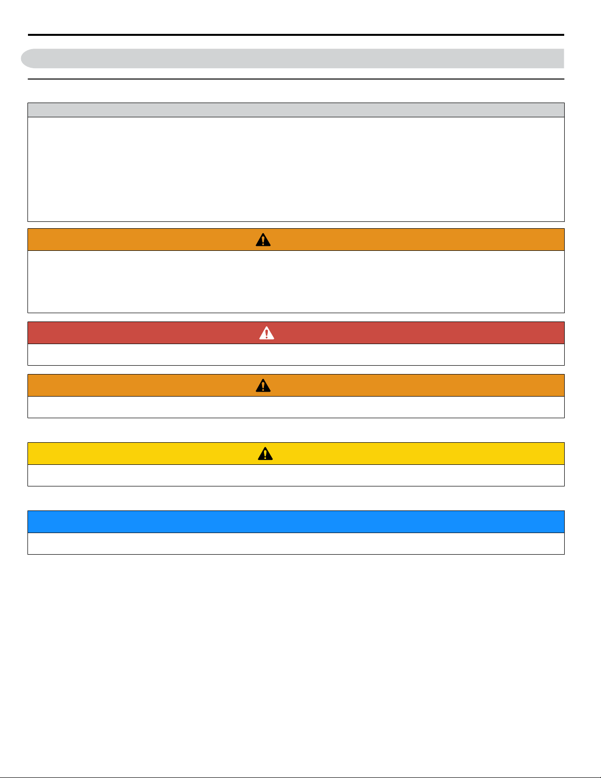
i.2 General Safety
i.2 General Safety
u
Supplemental Safety Information
General Precautions
• The diagrams in this manual may be indicated without covers or safety shields to show details. Replace the covers or shields before
operating the drive and run the drive according to the instructions described in this manual.
• Any illustrations, photographs, or examples used in this manual are provided as examples only and may not apply to all products to
which this manual is applicable.
• The products and specifications described in this manual or the content and presentation of the manual may be changed without notice
to improve the product and/or the manual.
• When ordering a new copy of the manual due to damage or loss, contact your Yaskawa representative or the nearest Yaskawa sales
office and provide the manual number shown on the front cover.
• If nameplate becomes worn or damaged, order a replacement from your Yaskawa representative or the nearest Yaskawa sales office.
WARNING
Read and understand this manual before installing, operating or servicing this drive. The drive must be installed according
to this manual and local codes.
The following conventions are used to indicate safety messages in this manual. Failure to heed these messages could result
in serious or fatal injury or damage to the products or to related equipment and systems.
DANGER
Indicates a hazardous situation, which, if not avoided, will result in death or serious injury.
WARNING
Indicates a hazardous situation, which, if not avoided, could result in death or serious injury.
WARNING! may also be indicated by a bold key word embedded in the text followed by an italicized safety message.
CAUTION
Indicates a hazardous situation, which, if not avoided, could result in minor or moderate injury.
CAUTION! may also be indicated by a bold key word embedded in the text followed by an italicized safety message.
NOTICE
Indicates a property damage message.
NOTICE: may also be indicated by a bold key word embedded in the text followed by an italicized safety message.
24
YASKAWA TOEP YAIP1W 01B YASKAWA AC Drive - iQpump1000 Quick Start Guide
Page 25

i.2 General Safety
u
Safety Messages
DANGER
Heed the safety messages in this manual.
Failure to comply will result in death or serious injury.
The operating company is responsible for any injuries or equipment damage resulting from failure to heed the warnings in
this manual.
Electrical Shock Hazard
Do not connect or disconnect wiring while the power is on.
Failure to comply will result in death or serious injury.
Before servicing, disconnect all power to the equipment. The internal capacitor remains charged even after the power supply
is turned off. After shutting off the power, wait for at least the amount of time specified on the drive before touching any
components.
WARNING
Sudden Movement Hazard
System may start unexpectedly upon application of power, resulting in death or serious injury.
Clear all personnel from the drive, motor and machine area before applying power. Secure covers, couplings, shaft keys and
machine loads before applying power to the drive.
Electrical Shock Hazard
Do not attempt to modify or alter the drive in any way not explained in this manual.
Failure to comply could result in death or serious injury.
Yaskawa is not responsible for any modification of the product made by the user. This product must not be modified.
Do not allow unqualified personnel to use equipment.
Failure to comply could result in death or serious injury.
Maintenance, inspection, and replacement of parts must be performed only by authorized personnel familiar with installation,
adjustment and maintenance of AC drives.
Do not remove covers or touch circuit boards while the power is on.
Failure to comply could result in death or serious injury.
Make sure the protective earthing conductor complies with technical standards and local safety regulations.
Because the leakage current exceeds 3.5 mA in models 4A0414 and larger, IEC/EN 61800-5-1 states that either the power
supply must be automatically disconnected in case of discontinuity of the protective earthing conductor or a protective
earthing conductor with a cross-section of at least 10 mm2 (Cu) or 16 mm2 (Al) must be used. Failure to comply may result
in death or serious injury.
Always use appropriate equipment for Ground Fault Circuit Interrupters (GFCIs).
The drive can cause a residual current with a DC component in the protective earthing conductor. Where a residual current
operated protective or monitoring device is used for protection in case of direct or indirect contact, always use a type B GFCI
according to IEC/EN 60755.
Fire Hazard
Do not use an improper voltage source.
Failure to comply could result in death or serious injury by fire.
Verify that the rated voltage of the drive matches the voltage of the incoming power supply before applying power.
Install adequate branch circuit protection according to applicable local codes and this Installation Manual. Failure
to comply could result in fire and damage to the drive or injury to personnel.
YASKAWA TOEP YAIP1W 01B YASKAWA AC Drive - iQpump1000 Quick Start Guide
25
Page 26
i.2 General Safety
WARNING
The device is suitable for use on a circuit capable of delivering not more than 100,000 RMS symmetrical amperes, 240 Vac
maximum (200 V class) and 480 Vac maximum (400 V class), and 600 Vac maximum (600 V class) when protected by
branch circuit protection devices specified in this document.
Crush Hazard
Do not use this drive in lifting applications without installing external safety circuitry to prevent accidental dropping
of the load.
The drive does not possess built-in load drop protection for lifting applications.
Failure to comply could result in death or serious injury from falling loads.
Install electrical and/or mechanical safety circuit mechanisms independent of drive circuitry.
CAUTION
Crush Hazard
Do not carry the drive by the front cover.
Failure to comply may result in minor or moderate injury from the main body of the drive falling.
NOTICE
Observe proper electrostatic discharge procedures (ESD) when handling the drive and circuit boards.
Failure to comply may result in ESD damage to the drive circuitry.
Do not perform a withstand voltage test on any part of the drive.
Failure to comply could result in damage to the sensitive devices within the drive.
Do not operate damaged equipment.
Failure to comply could result in further damage to the equipment.
Do not connect or operate any equipment with visible damage or missing parts.
If a fuse is blown or a Ground Fault Circuit Interrupter (GFCI) is tripped, check the wiring and the selection of the
peripheral devices.
Contact your supplier if the cause cannot be identified after checking the above.
Do not restart the drive immediately operate the peripheral devices if a fuse is blown or a GFCI is tripped.
Check the wiring and the selection of peripheral devices to identify the cause. Contact your supplier before restarting the
drive or the peripheral devices if the cause cannot be identified.
Do not expose the drive to halogen group disinfectants.
Failure to comply may cause damage to the electrical components in the drive.
Do not pack the drive in wooden materials that have been fumigated or sterilized.
Do not sterilize the entire package after the product is packed.
u
General Application Precautions
Selection
n
Installing a Reactor
Use an AC reactor or DC link choke in the following situations:
• to suppress harmonic current.
• to smooth peak current that results from capacitor switching.
• when the power supply is above 600 kVA.
• when the drive is running from a power supply system with thyristor converters.
Note: A DC link choke is built in to drive models 2A0110 to 2A0415, 4A0058 to 4A1200, and 5A0041 to 5A0242.
26
YASKAWA TOEP YAIP1W 01B YASKAWA AC Drive - iQpump1000 Quick Start Guide
Page 27

i.2 General Safety
4000
Power supply harmonics
reactor required
Power Supply
Capacity (kVA)
600
0
Drive Capacity (kVA)
Figure i.1 Installing a Reactor
Reactor
unnecessary
60 400
Single-Phase Input Selection
The drive is capable of single phase input. Refer to Main Circuit Connection Diagram on page 121 for connection diagrams
and Refer to Single-Phase Derating on page 317 for application instructions and drive current ratings.
Drive Capacity
For specialized motors, make sure that the motor rated current is less than the rated output current for the drive.
When running more than one motor in parallel from a single drive, the capacity of the drive should be larger than [total motor
rated current × 1.1].
Installation
n
Enclosure Panels
Keep the drive in a clean environment by installing the drive in an enclosure panel or selecting an installation area free of
airborne dust, lint, and oil mist. Be sure to leave the required space between drives to provide for cooling, and take proper
measures so the ambient temperature remains within allowable limits and keep flammable materials away from the drive.
Yaskawa offers protective designs for drives that must be used in areas subjected to oil mist and excessive vibration. Contact
Yaskawa or your Yaskawa agent for details.
Installation Direction
NOTICE: Install the drive upright as specified in the manual. Refer to Mechanical Installation on page 36 for more information on
installation. Failure to comply may damage the drive due to improper cooling.
Settings
n
Upper Limits
NOTICE: The drive is capable of running the motor up to 400 Hz. Be sure to set the upper limit for the frequency of the drive to prevent the
possible danger of accidentally operating equipment at higher than rated speed. The default setting for the maximum output frequency is
60 Hz.
Lower Limits
NOTICE: Many pumps have a minimum safe operating speed. Be sure to properly set the minimum pump speed in to protect the pump
from damage.
DC Injection Braking
NOTICE: Excessive current during DC Injection Braking and excessive duration of DC Injection Braking can cause motor overheat.
Acceleration/Deceleration Times
Acceleration and deceleration times are affected by the amount of torque generated by the motor, the load torque, and the
inertia moment. Set a longer accel/decel time when Stall Prevention is enabled. The accel/decel times are lengthened for as
long as the Stall Prevention function is in operation.
General Handling
n
Wiring Check
NOTICE: Do not connect power supply lines to output terminals U/T1, V/T2, or W/T3. Failure to comply will destroy the drive. Be sure to
perform a final check of all sequence wiring and other connections before turning on the power and also check for short circuits on the
control terminals, which may damage the drive.
Selecting a Circuit Breaker or Circuit Interrupter
Yaskawa recommends installing a Ground Fault Circuit Interrupter (GFCI) to the power supply side. The GFCI should be
designed for use with AC drives (e.g., Type B according to IEC 60755).
Select a Molded Case Circuit Breaker (MCCB) or GFCI with a rated current 1.5 to 2 times higher than the drive rated input
current to avoid nuisance trips caused by harmonics in the drive input current.
YASKAWA TOEP YAIP1W 01B YASKAWA AC Drive - iQpump1000 Quick Start Guide
27
Page 28

i.2 General Safety
Magnetic Contactor Installation
NOTICE: To get the full performance life out of the electrolytic capacitors and circuit relays, refrain from switching the drive power supply
off and on more than once every 30 minutes. Frequent use can damage the drive. Use the drive to stop and start the motor.
Inspection and Maintenance
WARNING! Electrical Shock Hazard. Capacitors in the drive do not immediately discharge after shutting off the power. Wait for at least the
amount of time specified on the drive before touching any components after shutting off the power. Failure to comply may cause injury to
personnel from electrical shock.
WARNING! Burn Hazard. Because the heatsink can get very hot during operation, take proper precautions to prevent burns. When replacing
the cooling fan, shut off the power and wait at least 15 minutes to be sure that the heatsink has cooled down. Failure to comply may cause
burn injury to personnel.
Wiring
Yaskawa recommends using ring terminals on all drive models. Drive models 2A0069 to 2A0415, 4A0058 to 4A1200, and
5A0041 to 5A0242 require the use of use ring terminals for UL/cUL compliance. Use only the tools recommended by the
terminal manufacturer for crimping.
Transporting the Drive
NOTICE: Never steam clean the drive. During transport, keep the drive from coming into contact with salts, fluorine, bromine, phthalate
ester, and other such harmful chemicals.
u
Motor Application Precautions
Standard Induction Motors
n
Insulation Tolerance
NOTICE: Consider motor voltage tolerance levels and motor insulation in applications with an input voltage of over 440 V or particularly
long wiring distances.
High-Speed Operation
NOTICE: Problems may occur with the motor bearings and dynamic balance of the machine when operating a motor beyond its rated speed.
Contact the motor or machine manufacturer.
Torque Characteristics
Torque characteristics differ compared to operating the motor directly from line power. The user should have a full
understanding of the load torque characteristics for the application.
Vibration and Shock
The drive allows selection of high carrier PWM control and low carrier PWM. Selecting high carrier PWM can help reduce
motor oscillation (drive current derating may be required).
Take particular caution when adding a variable speed drive to an application running a motor from line power at a constant
speed. If resonance occurs, use shock absorbing mounts to the motor base and enable the Jump frequency selection to prevent
continuous operation in the resonant frequency range.
Audible Noise
The audible noise of the motor varies based on the carrier frequency setting. However, drive current derating may be required.
When using a high carrier frequency, audible noise from the motor is comparable to the motor noise generated when running
from line power.
Specialized Motors
n
Submersible Motor
The rated current of a submersible motor is greater than that of a standard motor, so select the drive capacity accordingly. Use
a motor cable large enough to avoid decreasing the maximum torque level from voltage drop caused by a long motor cable.
Explosion-Proof Motor
The motor and the drive must be tested together to be certified as explosion-proof. The drive is not designed for explosionproof areas.
Geared Motor
Make sure that the gear and the lubricant are rated for the desired speed range to avoid gear damage when operating at low
speeds or very high speeds. Consult with the manufacturer for applications that require operation outside the rated speed range
of the motor or gear box.
28
YASKAWA TOEP YAIP1W 01B YASKAWA AC Drive - iQpump1000 Quick Start Guide
Page 29

i.2 General Safety
Single-Phase Motor
Variable speed drives are not designed to operate with single phase motors. Using capacitors to start the motor causes excessive
current to flow and can damage drive components. A split-phase start or a repulsion start can burn out the starter coils because
the internal centrifugal switch is not activated. The drive is for use with three-phase motors only.
Notes on Power Transmission Machinery
n
Installing an AC drive in machinery that was previously connected directly to the power supply will allow the machine to
operate at variable speeds. Continuous operation outside of the rated speeds can wear on lubrication material in gear boxes
and other power transmission parts. Make sure that lubrication is sufficient within the entire speed range to avoid machine
damage. Note that operation above the rated speed can increase the noise generated by the machine.
YASKAWA TOEP YAIP1W 01B YASKAWA AC Drive - iQpump1000 Quick Start Guide
29
Page 30
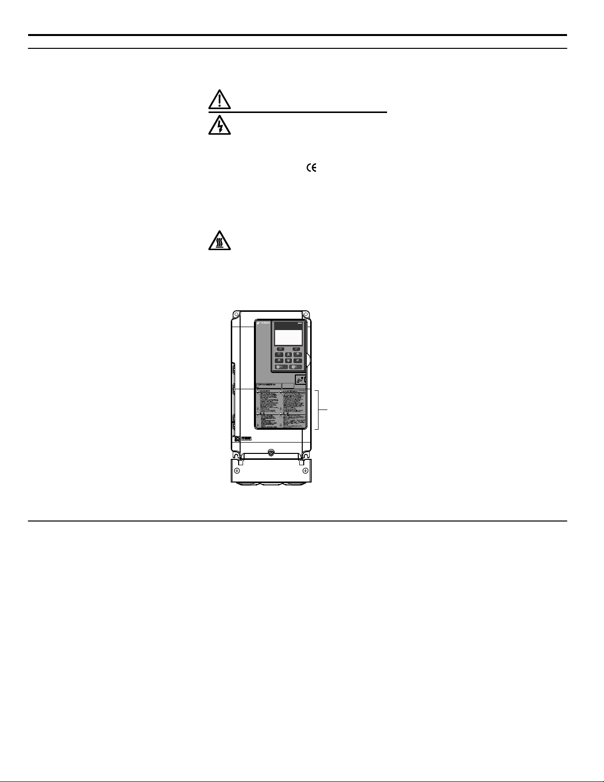
Warning Label
600V 3Phase 5.5kW/3.7kW
F2F1
ESC
M M
AUTO OFF
ENTERRESET
ALM
DIGITAL OPERATOR JVOP-183
HAND
i.2 General Safety
u
Drive Label Warning Example
Always heed the warning information listed in Figure i.2 in the position shown in Figure i.3.
WARNING
Risk of electric shock.
●
Read manual before installing.
●
Wait 5 minutes for capacitor
discharge after disconnecting
power supply.
●
To conform to requirements,
make sure to ground the supply
neutral for 400V class.
●
After opening the manual switch
between the drive and motor,
please wait 5 minutes before
inspecting, performing
maintenance or wiring the drive.
Hot surfaces
●
Top and Side surfaces may
become hot. Do not touch.
Figure i.2 Warning Information Example
Figure i.3 Warning Information Position
u
Warranty Information
Restrictions
n
The drive is not designed or manufactured for use in devices or systems that may directly affect or threaten human lives or
health.
Customers who intend to use the product described in this manual for devices or systems relating to transportation, health
care, space aviation, atomic power, electric power, or in underwater applications must first contact their Yaskawa
YASKAWA TOEP YAIP1W 01B YASKAWA AC Drive - iQpump1000 Quick Start Guide
representatives or the nearest Yaskawa sales office.
WARNING! Injury to Personnel. This product has been manufactured under strict quality-control guidelines. However, if this product is to
be installed in any location where failure of this product could involve or result in a life-and-death situation or loss of human life or in a facility
where failure may cause a serious accident or physical injury, safety devices must be installed to minimize the likelihood of any accident.
30
Page 31

1
Receiving
This chapter explains how to inspect the drive upon receipt, and gives an overview of the different
enclosure types and components.
1.1 MODEL NUMBER AND NAMEPLATE CHECK....................................................32
YASKAWA TOEP YAIP1W 01B YASKAWA AC Drive - iQpump1000 Quick Start Guide
31
Page 32

B
C
A
IND.CONT.EQ.
7J48 B
H
G
F
E
D
1.1 Model Number and Nameplate Check
1.1 Model Number and Nameplate Check
Please perform the following tasks after receiving the drive:
• Inspect the drive for damage.
If the drive appears damaged upon receipt, contact the shipper immediately.
• Verify receipt of the correct model by checking the information on the nameplate.
• If you have received the wrong model or the drive does not function properly, contact your supplier.
u
Nameplate
A – Normal Duty Amps
B – Software version
C – Enclosure type
D – Serial number
Figure 1.1 Nameplate Information Example
32
E – Lot number
F – Output specifications
G – Input specifications
H – AC drive model
YASKAWA TOEP YAIP1W 01B YASKAWA AC Drive - iQpump1000 Quick Start Guide
Page 33

CIMR
-
P W 2 A
0021 F
A A
Drive
P1000
Series
No.
Enclosure
Type <1>
Design
Revision
Order
No.
Customized
Specifications
A Standard model
IP00/Open
Type
F
IP20/NEMA
Type 1
A
No.
Environmental
Specification <3>
A Standard
Refer to the tables below
No.
Region
Code
Water
W
No. Voltage Class
3-phase, 380-480 Vac
3-phase, 200-240 Vac
2
4
3-phase, 500-600 Vac 5
U
Flange
Type <2>
1.1 Model Number and Nameplate Check
<1> Refer to Mechanical Installation on page 36 for differences regarding enclosure protection types and component
descriptions.
<2> Provides method of mounting drive with backside (heatsink) external to enclosure, with NEMA 12 integrity.
<3> Please contact Yaskawa for details regarding Environmental Specifications.
n
Three-Phase 200 V Class
Drive Model
2A0004 0.75 (0.75) 3.5
2A0006 1.1 (1) 6.0
2A0008 1.5 (2) 8.0
2A0010 2.2 (3) 9.6
2A0012 3.0 (3) 12
2A0018 3.7 (5) 17.5
2A0021 5.5 (7.5) 21
2A0030 7.5 (10) 30
2A0040 11 (15) 40
2A0056 15 (20) 56
2A0069 18.5 (25) 69
2A0081 22 (30) 81
2A0110 30 (40) 110
2A0138 37 (50) 138
2A0169 45 (60) 169
2A0211 55 (75) 211
2A0250 75 (100) 250
2A0312 90 (125) 312
2A0360 110 (150) 360
2A0415 110 (175) 415
Max. Motor Capacity kW (HP) Rated Output Current A
Receiving
1
YASKAWA TOEP YAIP1W 01B YASKAWA AC Drive - iQpump1000 Quick Start Guide
33
Page 34

1.1 Model Number and Nameplate Check
Three-Phase 400 V Class
n
Drive Model Max. Motor Capacity kW (HP) Rated Output Current A
4A0002 0.75 (0.75) 2.1
4A0004 1.5 (2) 4.1
4A0005 2.2 (3) 5.4
4A0007 3.0 (3) 6.9
4A0009 3.7 (5) 8.8
4A0011 5.5 (7.5) 11.1
4A0018 7.5 (10) 17.5
4A0023 11 (15) 23
4A0031 15 (20) 31
4A0038 18.5 (25) 38
4A0044 22 (30) 44
4A0058 30 (40) 58
4A0072 37 (50) 72
4A0088 45 (60) 88
4A0103 55 (75) 103
4A0139 75 (100) 139
4A0165 90 (125) 165
4A0208 110 (150) 208
4A0250 132 (200) 250
4A0296 160 (250) 296
4A0362 185 (300) 362
4A0414 220 (350) 414
4A0515 250 (400-450) 515
4A0675 355 (500-550) 675
4A0930 500 (750) 930
4A1200 630 (1000) 1200
Three-Phase 600 V Class
n
Drive Model
5A0003 1.5 (2) 2.7
5A0004 2.2 (3) 3.9
5A0006 3.7 (5) 6.1
5A0009 5.5 (7.5) 9
5A0011 7.5 (10) 11
5A0017 11 (15) 17
5A0022 15 (20) 22
5A0027 18.5 (25) 27
5A0032 22 (30) 32
5A0041 30 (40) 41
5A0052 37 (50) 52
5A0062 45 (60) 62
5A0077 55 (75) 77
5A0099 75 (100) 99
5A0125 90 (125) 125
5A0145 110 (150) 145
5A0192 160 (200) 192
5A0242 185 (250) 242
Max. Motor Capacity kW (HP) Rated Output Current A
Note: Refer to Single-Phase Derating on page 317 for Single-Phase ratings.
34
YASKAWA TOEP YAIP1W 01B YASKAWA AC Drive - iQpump1000 Quick Start Guide
Page 35

2
Mechanical Installation
This chapter explains how to properly mount and install the drive.
2.1 MECHANICAL INSTALLATION.............................................................................36
2.2 FLANGE TYPE ENCLOSURE (NEMA 12 BACKSIDE) DIMENSIONS & HEAT
LOSS......................................................................................................................53
YASKAWA TOEP YAIP1W 01B YASKAWA AC Drive - iQpump1000 Quick Start Guide
35
Page 36

2.1 Mechanical Installation
2.1 Mechanical Installation
This section outlines specifications, procedures, and the environment for proper mechanical installation of the drive.
u
Installation Environment
Install the drive in an environment matching the specifications in Table 2.1 to help prolong the optimum performance life of
the drive.
Table 2.1 Installation Environment
Environment Conditions
Installation Area Indoors
-10 °C to +40 °C (IP20/NEMA Type 1 enclosure)
-10 °C to +50 °C (IP00/Open Type enclosure)
Ambient Temperature
Humidity 95% RH or less and free of condensation
Storage Temperature -20 to +60 °C
Surrounding Area
Altitude 1000 m or lower, up to 3000 m with derating
Vibration
Orientation Install the drive vertically to maintain maximum cooling effects.
<1>
Models 4A0930 and 4A1200 are rated at 5.9 m/s2 (19.36 ft/s2)
NOTICE: Avoid placing drive peripheral devices, transformers, or other electronics near the drive as the noise created can lead to erroneous
operation. If such devices must be used in close proximity to the drive, take proper steps to shield the drive from noise.
NOTICE: Prevent foreign matter such as metal shavings and wire clippings from falling into the drive during installation. Failure to comply
could result in damage to the drive. Place a temporary cover over the top of the drive during installation. Remove the temporary cover before
drive start-up, as the cover will reduce ventilation and cause the drive to overheat.
Drive reliability improves in environments without wide temperature fluctuations.
When using the drive in an enclosure panel, install a cooling fan or air conditioner in the area to ensure that the air
temperature inside the enclosure does not exceed the specified levels.
Do not allow ice to develop on the drive.
Install the drive in an area free from:
• oil mist and dust
• metal shavings, oil, water, or other foreign materials
• radioactive materials
• combustible materials (e.g., wood)
• harmful gases and liquids
• excessive vibration
• chlorides
• direct sunlight.
10 to 20 Hz at 9.8 m/s2 (32.15 ft/s2)
20 to 55 Hz at 5.9 m/s2 (19.36 ft/s2) (Models 2A0004 to 2A0211, 4A0002 to 4A0165, and 5A0003 to 5A0099) or
2.0 m/s2 (6.56 ft/s2) (Models 2A0250 to 2A0415, 4A0208 to 4A1200, and 5A0125 to 5A0242)
<1>
u
Installation Orientation and Spacing
Install the drive upright as illustrated in Figure 2.1 to maintain proper cooling.
Figure 2.1 Correct Installation Orientation
NOTICE:
36
Install the drive upright as specified in the manual. Failure to comply may damage the drive due to improper cooling.
YASKAWA TOEP YAIP1W 01B YASKAWA AC Drive - iQpump1000 Quick Start Guide
Page 37

A
A
B B
Side Clearance Top/Bottom Clearance
C
C
D
D
A
A
A
A
B
C
B
Side Clearance
Line up the tops of the drives.
D
D
Top/Bottom Clearance
2.1 Mechanical Installation
Single Drive Installation
n
Figure 2.2 shows the installation distance required to maintain sufficient space for airflow and wiring. Install the heatsink
against a closed surface to avoid diverting cooling air around the heatsink.
A – 50 mm minimum
B – 30 mm minimum
C – 120 mm minimum
D – Airflow direction
Figure 2.2 Correct Installation Spacing
Note: IP20/NEMA Type 1 enclosure and IP00/Open Type enclosure models require the same amount of space above and below the drive for
installation.
Multiple Drive Installation (Side-by-Side Installation)
n
Models 2A0004 to 2A0081, 4A0002 to 4A0044, and 5A0003 to 5A0032 can take advantage of Side-by-Side installation.
When installing multiple drives into the same enclosure panel, mount the drives according to Figure 2.2 and set L8-35,
Installation Method Selection, to 1 (Side-by-Side Mounting).
When mounting drives with the minimum clearance of 2 mm according to Figure 2.3, set parameter L8-35 to 1 while
considering derating. Refer to Parameter List on page 325 for details.
Mechanical Installation
2
Note: Align the tops of the drives when installing drives of different heights in the same enclosure panel. Leave space between the tops and bottoms
of stacked drives for easier cooling fan replacement.
YASKAWA TOEP YAIP1W 01B YASKAWA AC Drive - iQpump1000 Quick Start Guide
A – 50 mm minimum
B – 30 mm minimum
Figure 2.3 Space Between Drives (Side-by-Side Mounting)
C – 2 mm minimum
D – 120 mm minimum
37
Page 38

B
A
C
D
2.1 Mechanical Installation
Remove the top protective covers of all drives as shown in Figure 2.4 when mounting IP20/NEMA Type 1 enclosure drives
side-by-side. Refer to Top Protective Cover on page 130 to remove and reattach the top protective cover.
Figure 2.4 IP20/NEMA 1 Side-by-Side Mounting in Enclosure
u
Instructions on Installation Using the Eye Bolts
Eye bolts are used to install the drive or to temporarily lift the drive when replacing it. Using the eye bolts, the drive can be
installed in an enclosure panel or on a wall. Do not leave the drive suspended by the wires in a horizontal or vertical position
for long periods of time. Do not transport the drive over long distances. Read the following precautions and instructions before
installing the drive.
WARNING! Crush Hazard. Observe the following instructions and precautions. Failure to comply could result in serious injury or death from
falling equipment.
Only use vertical suspension to temporarily lift the drive during installation to an enclosure panel. Do not use vertical suspension to transport
the drive.
Use screws to securely affix the drive front cover, terminal blocks, and other drive components prior to vertical suspension.
Do not subject the drive to vibration or impact greater than 1.96 m/s2 (0.2 G) while it is suspended by the wires.
Do not leave the drive unattended while it is suspended by the wires.
Do not attempt to flip the drive over while it is suspended by the wires.
Horizontal Suspension of Drive Models 2A0360, 2A0415, and 4A0250 to 4A0675
n
To make a wire hanger or frame for use when lifting the drive with a crane, lay the drive in a horizontal position and pass a
wire through the holes of the four eye bolts.
NOTICE: Damage to Equipment. When lifting the drive, confirm that the spring washer is fully closed. Failure to comply may deform or
damage the drive when lifted.
A – No space between drive and
washer
B – Spring washer fully closed
Figure 2.5 Spring Washer
C – Space between drive and washer
D – Spring washer open
38
YASKAWA TOEP YAIP1W 01B YASKAWA AC Drive - iQpump1000 Quick Start Guide
Page 39

Eye bolt
A
B
C
2.1 Mechanical Installation
Vertical Suspension of Drive Models 2A0360, 2A0415, and 4A0250 to 4A1200
n
Models 2A0360, 2A0415, and 4A0250 to 4A0675
When vertical suspension of the drive is required in an enclosure panel, change the orientation of the eye bolts for these models
by turning the eye bolts counterclockwise 90 degrees.
Figure 2.6 Adjusting Angle of Eye Bolts
Models 4A0930 and 4A1200
When suspending models 4A0930 or 4A1200 with wires, follow the procedure described below.
WARNING! Crush Hazard. Use an adequate length of wire to ensure a 50° or wider suspension angle as illustrated in Figure 2.8. The
maximum allowable load of the eye bolts cannot be guaranteed when the drive is suspended with the wires at angles less than 50°. Failure
to comply may result in serious injury or death from falling equipment.
Remove the four eye bolts from the drive side panels and fix them securely on the top panel.
1.
Figure 2.7 Eye Bolt Repositioning
Pass wire through the holes of all four eye bolts.
2.
YASKAWA TOEP YAIP1W 01B YASKAWA AC Drive - iQpump1000 Quick Start Guide
A – Eye bolt
B – Wires
Figure 2.8 Suspension Wire Angle Example
Mechanical Installation
2
C – Suspending angle: 50° or greater
39
Page 40

Drive
Comm Port
HOA Keypad
Communication Cable Connector
Unit: mm (in)
Installation Holes (2-M3 Screws, Depth 5)
78 (3.07)
15 (0.59)
44 (1.73)
2.1 Mechanical Installation
Gradually take up the slack in the wires and hoist the drive after the wires are stretched tight.
3.
Lower the drive when ready to install in the enclosure panel. Stop lowering the drive when it is near the floor then
4.
begin lowering the drive again very slowly until the drive is placed correctly.
u
HOA Keypad Remote Usage
Remote Operation
n
The HOA keypad mounted on the drive can be removed and connected to the drive using an extension cable up to 3 m (9.8
ft.) long to facilitate operation when the drive is installed in a location where it can not be easily accessed.
The HOA keypad can also be permanently mounted remote locations such as panel doors using an extension cable and an
installation support set (depending on the installation type).
Note: Refer to Peripheral Devices & Options on page 297 for information on extension cables and installation support sets.
Figure 2.9 Communication Cable Connection
HOA Keypad Remote Installation
n
HOA Keypad Dimensions
Installation Types and Required Materials
The HOA keypad mounts to an enclosure two different ways:
• External/face-mount installs the HOA keypad outside the enclosure panel
Figure 2.10 HOA Keypad Dimensions
• Internal/flush-mount installs the HOA keypad inside the enclosure panel
40
YASKAWA TOEP YAIP1W 01B YASKAWA AC Drive - iQpump1000 Quick Start Guide
Page 41

22 (0.87)
14 (0.56)
26 (1.02)
78 (3.1)
2 (0.08)
Unit: mm (in)
22 (0.87)
22 (0.87)
HOA Keypad
M3 x 6
Phillips recessed
pan head machine screw x 2
Enclosure panel
2.1 Mechanical Installation
Table 2.2 HOA Keypad Installation Methods and Required Tools
Installation
Method
External/
Face-Mount
Internal/
Flush-Mount
NOTICE: Prevent foreign matter such as metal shavings or wire clippings from falling into the drive during installation and project
construction. Failure to comply could result in damage to the drive. Place a temporary cover over the top of the drive during installation.
Remove the temporary cover before drive start-up, as the cover will reduce ventilation and cause the drive to overheat.
Simplified installation with the
HOA keypad is mounted on the
outside of the panel with two
screws.
Encloses the HOA keypad in
the panel. The front of the HOA
keypad is flush with the outside
of the panel.
Description
External/Face-Mount
Cut an opening in the enclosure panel for the HOA keypad as shown in Figure 2.11.
1.
Position the HOA keypad so the display faces outwards, and mount it to the enclosure panel as shown in Figure
2.
2.12.
Installation
Support Sets
– –
Installation Support Set A
(for mounting with screws
through holes in the panel)
Installation Support Set B
(for use with threaded studs
that are fixed to the panel)
Model Required Tools
Phillips screwdriver
(#1)
EZZ020642A
EZZ020642B
Phillips screwdriver
(#1, #2)
Phillips screwdriver (#1)
Wrench (7 mm)
Internal/Flush-Mount
An internal/flush-mount requires an installation support set that must be purchased separately. Contact Yaskawa to order an
installation support set and mounting hardware. Figure 2.13 illustrates how to attach the Installation Support Set A.
Figure 2.11 Panel Cut-Out Dimensions (External/Face-Mount Installation)
Figure 2.12 External/Face-Mount Installation
Cut an opening in the enclosure panel for the HOA keypad as shown in Figure 2.14.
1.
Mount the HOA keypad to the installation support.
2.
Mount the installation support set and HOA keypad to the enclosure panel.
3.
Mechanical Installation
2
YASKAWA TOEP YAIP1W 01B YASKAWA AC Drive - iQpump1000 Quick Start Guide
41
Page 42

Enclosure panel
Unit: mm (in)
HOA Keypad
Installation Support Set A
M4 × 10
Phillips truss head screw × 4
(for panel widths between 1 (0.04) and 1.6 (0.06))
M3 × 6
Phillips recessed
pan head machine screw × 2
120 (4.72)
45 (1.77)
59 (2.32)
+0.5 (0.02)
0
89 (3.5)
+0.5 (0.02)
0
Unit : mm (in)
2.1 Mechanical Installation
Figure 2.13 Internal/Flush Mount Installation
Note: Use a gasket between the enclosure panel and the HOA keypad in environments with a significant amount of dust or other airborne debris.
Figure 2.14 Panel Cut-Out Dimensions (Internal/Flush-Mount Installation)
42
YASKAWA TOEP YAIP1W 01B YASKAWA AC Drive - iQpump1000 Quick Start Guide
Page 43

2.1 Mechanical Installation
u
Exterior and Mounting Dimensions
Table 2.3 Drive Models and Types
Drive Model
Protective Design
IP20/NEMA Type 1
Enclosure
IP00/Open Type
Enclosure
Three-Phase
200 V Class
2A0004F
2A0006F
2A0008F
2A0010F
2A0012F
2A0018F
2A0021F
2A0030F
2A0040F
2A0056F
2A0069F
2A0081F
2A0110F
2A0138F
2A0169F
2A0211F
2A0250A
2A0312A
2A0360A
2A0415A
<1>
<1>
<1>
<2>
Three-Phase
400 V Class
4A0002F
4A0004F
4A0005F
4A0007F
4A0009F
4A0011F
4A0018F
4A0023F
4A0031F
4A0038F
4A0044F
4A0058F
4A0072F
4A0088F
4A0103F
4A0139F
4A0165F
4A0208A
4A0250A
4A0296A
4A0362A
4A0414A
4A0515A
4A0675A
4A0930A
4A1200A
<1>
<1>
<1>
<1>
<2>
<2>
<2>
<2>
<2>
Three-Phase
600 V Class
5A0003F
5A0004F
5A0006F
5A0009F
5A0011F
5A0017F
5A0022F
5A0027F
5A0032F
5A0041F
5A0052F
5A0062F
5A0077F
5A0099F
5A0125A
5A0145A
5A0192A
5A0242A
<1>
<1>
<1>
<1>
4A0002U
4A0004U
4A0005U
Flange Type
Enclosure (NEMA
12 Backside)
2A0004U
2A0006U
2A0008U
2A0010U
2A0012U
2A0018U
2A0021U
2A0030U
2A0040U
2A0056U
2A0069U
2A0081U
2A0110U
2A0138U
2A0169U
2A0211U
2A0250U
2A0312U
2A0360U
2A0415U
4A0007U
4A0009U
4A0011U
4A0018U
4A0023U
4A0031U
4A0038U
4A0044U
4A0058U
4A0072U
4A0088U
4A0103U
4A0139U
4A0165U
4A0208U
4A0250U
4A0296U
4A0362U
4A0414U
4A0515U
5A0003U
5A0004U
5A0006U
5A0009U
5A0011U
5A0017U
5A0022U
5A0027U
5A0032U
5A0041U
5A0052U
5A0062U
5A0077U
5A0099U
5A0125U
5A0145U
5A0192U
5A0242U
4A0675U
4A0930U
4A1200U
<1> Customers may convert these models to IP20/NEMA Type 1 enclosures using an IP20/NEMA Type 1 Kit. Refer to IP20/NEMA Type 1 Kit
Selection on page 52 to select the appropriate kit.
<2> Contact a Yaskawa representative for IP20/NEMA Type 1 Kit availability for these models.
Page
44
50
53
Mechanical Installation
2
YASKAWA TOEP YAIP1W 01B YASKAWA AC Drive - iQpump1000 Quick Start Guide
43
Page 44

W1
4-d
H1
H
H0
H2
H3
W
Max.W2
D
D1
t2
t1
Figure 2Figure 1
W1
H4
H
H0
H1
H3
H2
D
D1
t1
4-d
W
Max.W2
2.1 Mechanical Installation
IP20/NEMA Type 1 Enclosure Drives
n
Note: Removing the top protective cover or bottom conduit bracket from an IP20/NEMA Type 1 enclosure drive voids NEMA Type 1 protection
while maintaining IP20 conformity.
Drive Model Figure
2A0004F
2A0006F
2A0008F
2A0010F
2A0012F
2A0018F
2A0021F
2A0030F
2A0040F
2A0056F
2A0069F
2A0081F
2A0110F
2A0138F
2A0169F
2A0211F
44
Table 2.4 Dimensions for IP20/NEMA Type 1 Enclosure: 200 V Class
Dimensions mm (in)
W H D W1 W2 H0 H1 H2 H3 H4 D1 t1 t2 d
140
(5.51)
140
(5.51)
140
(5.51)
140
(5.51)
140
(5.51)
140
(5.51)
1
<1>
140
(5.51)
140
(5.51)
140
(5.51)
180
(7.09)
220
(8.66)
220
(8.66)
254
(10.00)
279
(10.98)
2
<1>
329
(12.95)
329
(12.95)
300
(11.81)
300
(11.81)
300
(11.81)
300
(11.81)
300
(11.81)
300
(11.81)
300
(11.81)
300
(11.81)
300
(11.81)
340
(13.39)
400
(15.75)
400
(15.75)
534
(21.02)
614
(24.17)
730
(28.74)
730
(28.74)
147
(5.79)
147
(5.79)
147
(5.79)
147
(5.79)
147
(5.79)
164
(6.46)
164
(6.46)
167
(6.57)
167
(6.57)
187
(7.36)
197
(7.76)
197
(7.76)
258
(10.16)
258
(10.16)
283
(11.14)
283
(11.14)
(4.80)
(4.80)
(4.80)
(4.80)
(4.80)
(4.80)
(4.80)
(4.80)
(4.80)
(6.30)
(7.56)
(7.56)
(7.68)
(8.66)
(10.24)
(10.24)
122
122
122
122
122
122
122
122
122
160
192
192
195
220
260
260
7.9
(0.31)
7.9
(0.31)
7.9
(0.31)
7.9
(0.31)
260
–
(10.24)
–
(10.24)
–
(10.24)
–
(10.24)
–
(10.24)
–
(10.24)
–
(10.24)
–
(10.24)
–
(10.24)
–
(11.81)
–
(13.78)
–
(13.78)
(15.75)
(17.72)
(21.65)
(21.65)
248
(9.76)6(0.24)40(1.57)
260
248
(9.76)6(0.24)40(1.57)
260
248
(9.76)6(0.24)40(1.57)
260
248
(9.76)6(0.24)40(1.57)
260
248
(9.76)6(0.24)40(1.57)
260
248
(9.76)6(0.24)40(1.57)
260
248
(9.76)6(0.24)40(1.57)
260
248
(9.76)6(0.24)40(1.57)
260
248
(9.76)6(0.24)40(1.57)
300
284
(11.18)
350
335
(13.19)
350
335
(13.19)
400
385
(15.16)
450
435
(17.13)
550
535
(21.06)
550
535
(21.06)
YASKAWA TOEP YAIP1W 01B YASKAWA AC Drive - iQpump1000 Quick Start Guide
7.9
(0.31)40(1.57)
7.9
(0.31)50(1.97)
7.9
(0.31)50(1.97)
7.7
(0.30)
(5.28)
7.7
(0.30)
(6.46)
7.7
(0.30)
(7.09)
7.7
(0.30)
(7.09)
1.5
(0.06)38(1.50)5(0.20)
1.5
(0.06)38(1.50)5(0.20)
1.5
(0.06)38(1.50)5(0.20)
1.5
(0.06)38(1.50)5(0.20)
1.5
(0.06)38(1.50)5(0.20)
1.5
(0.06)55(2.17)5(0.20)
1.5
(0.06)55(2.17)5(0.20)
1.5
(0.06)55(2.17)5(0.20)
1.5
(0.06)55(2.17)5(0.20)
1.5
(0.06)75(2.95)5(0.20)
1.5
(0.06)78(3.07)5(0.20)
1.5
(0.06)78(3.07)5(0.20)
134
1.5
(0.06)
164
180
180
–
–
–
100
(3.94)
100
(3.94)
110
(4.33)
110
(4.33)
2.2
(0.09)
2.2
(0.09)
2.2
(0.09)
2.2
(0.09)
– M5
– M5
– M5
– M5
– M5
– M5
– M5
– M5
– M5
– M5
– M6
– M6
2.286
(0.09)
2.286
(0.09)
2.286
(0.09)
2.286
(0.09)
M6
M6
M6
M6
Wt. kg
(lb)
3.3
(7.3)
3.3
(7.3)
3.4
(7.5)
3.4
(7.5)
3.4
(7.5)
3.8
(8.2)
3.8
(8.2)
4.2
(9.3)
4.2
(9.3)
5.9
(13.0)
9
(20.1)
10
(22.0)
23
(50.7)
28
(61.7)
41
(90.4)
42
(92.6)
Page 45

2.1 Mechanical Installation
Dimensions mm (in)
Drive Model Figure
Dimensions below are the dimensions of IP00/Open Type models after customer installation of the appropriate IP20/NEMA Type 1 Kit.
2A0250A
2A0312A
2A0360A
2
W H D W1 W2 H0 H1 H2 H3 H4 D1 t1 t2 d
456
(17.95)
456
(17.95)
194
(19.84)
960
(37.80)
960
(37.80)
1168
(45.98)35(13.78)
330
(12.99)
330
(12.99)
325
(12.80)
325
(12.80)
370
(14.57)
7.9
(0.31)28(27.76)
7.9
(0.31)28(27.76)
7.9
(0.31)
800
(31.50)
680
(26.77)12(0.49)
680
(26.77)12(0.49)
773
(30.43)13(0.51)
255
(10.04)
255
(10.04)
368
(14.49)
130
–
(5.12)
130
–
(5.12)
130
–
(5.12)
3.3
(0.13)
3.3
(0.13)
4.6
(0.18)
3.3
(0.13)
3.30
(0.13)
4.6
(0.18)
M10
M10
M12
Wt. kg
(lb)
83
(183.0)
88
(194.0)
108
(238.1)
<1> Removing the top protective cover from a IP20/NEMA Type 1 enclosure drive voids NEMA Type 1 protection while retaining IP20 conformity.
Table 2.5 Dimensions for IP20/NEMA Type 1 Enclosure: 400 V Class
Drive Model Figure
4A0002F
4A0004F
4A0005F
4A0007F
4A0009F
4A0011F
4A0018F
4A0023F
4A0031F
4A0038F
4A0044F
4A0058F
4A0072F
4A0088F
4A0103F
4A0139F
4A0165F
Dimensions below are the dimensions of IP00/Open Type models after customer installation of the appropriate IP20/NEMA Type 1 Kit.
4A0208A
4A0250A
4A0296A
4A0362A
1
<1>
2
<1>
2
W H D W1 W2 H0 H1 H2 H3 H4 D1 t1 t2 d
140
(5.51)
140
(5.51)
140
(5.51)
140
(5.51)
140
(5.51)
140
(5.51)
140
(5.51)
140
(5.51)
180
(7.09)
180
(7.09)
220
(8.66)
254
(10.00)
279
(10.98)
329
(12.95)
329
(12.95)
329
(12.95)
329
(12.95)
456
(17.95)
194
(19.84)
194
(19.84)
194
(19.84)
300
(11.81)
300
(11.81)
300
(11.81)
300
(11.81)
300
(11.81)
300
(11.81)
300
(11.81)
300
(11.81)
340
(13.39)
340
(13.39)
400
(15.75)
465
(18.31)
515
(20.28)
630
(24.80)
630
(24.80)
730
(28.74)
730
(28.74)
960
(37.80)
1168
(45.98)35(13.78)
1168
(45.98)35(13.78)
1168
(45.98)35(13.78)
147
(5.79)
147
(5.79)
147
(5.79)
164
(6.46)
164
(6.46)
164
(6.46)
167
(6.57)
167
(6.57)
167
(6.57)
187
(7.36)
197
(7.76)
258
(10.16)
258
(10.16)
258
(10.16)
258
(10.16)
283
(11.14)
283
(11.14)
330
(12.99)
122
(4.80)
122
(4.80)
122
(4.80)
122
(4.80)
122
(4.80)
122
(4.80)
122
(4.80)
122
(4.80)
160
(6.30)
160
(6.30)
195
(7.68)
195
(7.68)
220
(8.66)
260
(10.24)
260
(10.24)
260
(10.24)
260
(10.24)
325
(12.80)
370
(14.57)
370
(14.57)
370
(14.57)
–
–
–
–
–
–
–
–
–
–
–
7.9
(0.31)
7.9
(0.31)
7.9
(0.31)
7.9
(0.31)
7.9
(0.31)
7.9
(0.31)
7.9
(0.31)28(27.76)
7.9
(0.31)
7.9
(0.31)
7.9
(0.31)
Dimensions mm (in)
260
(10.24)
(10.24)
(10.24)
(10.24)
(10.24)
(10.24)
(10.24)
(10.24)
(11.81)
(11.81)
(13.78)
(15.75)
(17.72)
(20.08)
(20.08)
(21.65)
(21.65)
(31.50)
(31.50)
(31.50)
248
(9.76)6(0.24)40(1.57)
260
248
(9.76)6(0.24)40(1.57)
260
248
(9.76)6(0.24)40(1.57)
260
248
(9.76)6(0.24)40(1.57)
260
248
(9.76)6(0.24)40(1.57)
260
248
(9.76)6(0.24)40(1.57)
260
248
(9.76)6(0.24)40(1.57)
260
248
(9.76)6(0.24)40(1.57)
300
284
(11.18)
300
284
(11.18)
35
335
(13.19)
400
385
(15.16)
450
435
(17.13)
509
495
(19.49)
509
495
(19.49)
550
535
(21.06)
550
535
(21.06)
680
(26.77)12(0.49)
800
773
(30.43)13(0.51)
800
773
(30.43)13(0.51)
800
773
(30.43)13(0.51)
(0.31)40(1.57)
(0.31)40(1.57)
(0.31)50(1.97)
(0.30)65(2.56)
(0.30)65(2.56)
(0.30)
(0.30)
(0.30)
(0.30)
7.9
7.9
7.9
7.7
7.7
7.7
7.7
7.7
7.7
120
(4.72)
120
(4.72)
180
(7.09)
180
(7.09)
255
(10.04)
368
(14.49)
368
(14.49)
368
(14.49)
1.5
(0.06)38(1.50)5(0.20)
1.5
(0.06)38(1.50)5(0.20)
1.5
(0.06)38(1.50)5(0.20)
1.5
(0.06)55(2.17)5(0.20)
1.5
(0.06)55(2.17)5(0.20)
1.5
(0.06)55(2.17)5(0.20)
1.5
(0.06)55(2.17)5(0.20)
1.5
(0.06)55(2.17)5(0.20)
1.5
(0.06)55(2.17)5(0.20)
1.5
(0.06)75(2.95)5(0.20)
1.5
(0.06)78(3.07)5(0.20)
100
–
(3.94)
100
–
(3.94)
105
–
(4.13)
105
–
(4.13)
110
–
(4.33)
110
–
(4.33)
130
–
(5.12)
130
–
(5.12)
130
–
(5.12)
130
–
(5.12)
2.2
(0.09)
2.2
(0.09)
2.2
(0.09)
2.2
(0.09)
2.2
(0.09)
2.2
(0.09)
3.3
(0.13)
4.6
(0.18)
4.6
(0.18)
4.6
(0.18)
2.2
(0.09)
2.2
(0.09)
3.3
(0.13)
3.3
(0.13)
2.2
(0.09)
2.2
(0.09)
3.3
(0.13)
4.6
(0.18)
4.6
(0.18)
4.6
(0.18)
– M5
– M5
– M5
– M5
– M5
– M5
– M5
– M5
– M5
– M5
– M6
M6
M6
M6
M6
M6
M6
M10
M12
M12
M12
Wt. kg
(lb)
3.4
(7.5)
3.4
(7.5)
3.4
(7.5)
3.6
(7.9)
3.8
(8.2)
3.8
(8.2)
4.0
(9.0)
4.0
(9.0)
5.8
(12.6)
6.0
(13.2)
8.8
(19.2)
23
(50.7)
27
(59.5)
39
(86.0)
39
(86.0)
45
(99.2)
46
(101.4)
87
(191.8)
106
(233.7)
112
(246.9)
117
(257.9)
<1> Removing the top protective cover from a IP20/NEMA Type 1 enclosure drive voids NEMA Type 1 protection while retaining IP20 conformity.
Mechanical Installation
2
YASKAWA TOEP YAIP1W 01B YASKAWA AC Drive - iQpump1000 Quick Start Guide
45
Page 46

2.1 Mechanical Installation
Table 2.6 Dimensions for IP20/NEMA Type 1 Enclosure: 600 V Class
Drive Model Figure
5A0003F
5A0004F
5A0006F
5A0009F
5A0011F
5A0017F
5A0022F
5A0027F
5A0032F
5A0041F
5A0052F
5A0062F
5A0077F
5A0099F
Dimensions below are the dimensions of IP00/Open Type models after customer installation of the appropriate IP20/NEMA Type 1 Kit.
5A0125A
5A0145A
5A0192A
5A0242A
1
<1>
2
2
W H D W1 W2 H0 H1 H2 H3 H4 D1 t1 t2 d
140
(5.51)
140
(5.51)
140
(5.51)
140
(5.51)
140
(5.51)
180
(7.09)
180
(7.09)
220
(8.66)
220
(8.66)
279
(10.98)
279
(10.98)
329
(12.95)
329
(12.95)
329
(12.95)
456
(17.95)
456
(17.95)
194
(19.84)
194
(19.84)
300
300
300
300
300
340
340
400
400
515
515
730
730
730
960
960
147
(5.79)
147
(5.79)
164
(6.46)
164
(6.46)
167
(6.57)
187
(7.36)
187
(7.36)
197
(7.76)
197
(7.76)
258
(10.16)
258
(10.16)
283
(11.14)
283
(11.14)
283
(11.14)
330
(12.99)
330
(12.99)
(11.81)
(11.81)
(11.81)
(11.81)
(11.81)
(13.39)
(13.39)
(15.75)
(15.75)
(20.28)
(20.28)
(28.74)
(28.74)
(28.74)
(37.80)
(37.80)
1168
(45.98)35(13.78)
1168
(45.98)35(13.78)
122
(4.80)
122
(4.80)
122
(4.80)
122
(4.80)
122
(4.80)
160
(6.30)
160
(6.30)
192
(7.56)
192
(7.56)
220
(8.66)
220
(8.66)
260
(10.24)
260
(10.24)
260
(10.24)
325
(12.80)
325
(12.80)
370
(14.57)
370
(14.57)
–
–
–
–
–
–
–
–
–
7.9
(0.31)
7.9
(0.31)
7.9
(0.31)
7.9
(0.31)
7.9
(0.31)
7.9
(0.31)28(27.76)
7.9
(0.31)28(27.76)
7.9
(0.31)
7.9
(0.31)
Dimensions mm (in)
260
(10.24)
260
(10.24)
260
(10.24)
260
(10.24)
260
(10.24)
300
(11.81)
300
(11.81)
(13.78)
(13.78)
450
(17.72)
450
(17.72)
550
(21.65)
550
(21.65)
550
(21.65)
800
(31.50)
800
(31.50)
248
(9.76)6(0.24)40(1.57)
248
(9.76)6(0.24)40(1.57)
248
(9.76)6(0.24)40(1.57)
248
(9.76)6(0.24)40(1.57)
248
(9.76)6(0.24)40(1.57)
284
(11.18)
284
(11.18)
35
335
(13.19)
35
335
(13.19)
435
(17.13)
435
(17.13)
535
(21.06)
535
(21.06)
535
(21.06)
680
(26.77)12(0.49)
680
(26.77)12(0.49)
773
(30.43)13(0.51)
773
(30.43)13(0.51)
(0.31)40(1.57)
(0.31)40(1.57)
(0.31)50(1.97)
(0.31)50(1.97)
(0.30)65(2.56)
(0.30)65(2.56)
(0.30)
(0.30)
(0.30)
7.9
7.9
7.9
7.9
7.7
7.7
7.7
7.7
7.7
180
(7.09)
180
(7.09)
180
(7.09)
255
(10.04)
255
(10.04)
368
(14.49)
368
(14.49)
1.5
(0.06)38(1.50)5(0.20)
1.5
(0.06)38(1.50)5(0.20)
1.5
(0.06)55(2.17)5(0.20)
1.5
(0.06)55(2.17)5(0.20)
1.5
(0.06)55(2.17)5(0.20)
1.5
(0.06)75(2.95)5(0.20)
1.5
(0.06)75(2.95)5(0.20)
1.5
(0.06)78(3.07)5(0.20)
1.5
(0.06)78(3.07)5(0.20)
100
–
(3.94)
100
–
(3.94)
110
–
(4.33)
110
–
(4.33)
110
–
(4.33)
130
–
(5.12)
130
–
(5.12)
130
–
(5.12)
130
–
(5.12)
2.2
(0.09)
2.2
(0.09)
2.2
(0.09)
2.2
(0.09)
2.2
(0.09)
3.3
(0.13)
3.3
(0.13)
4.6
(0.18)
4.6
(0.18)
– M5
– M5
– M5
– M5
– M5
– M5
– M5
– M6
– M6
2.2
(0.09)
2.2
(0.09)
2.2
(0.09)
2.2
(0.09)
2.2
(0.09)
3.3
(0.13)
3.3
(0.13)
4.6
(0.18)
4.6
(0.18)
<1> Removing the top protective cover or bottom conduit bracket from an IP20/NEMA Type 1 enclosure drive voids NEMA Type 1 protection while
maintaining IP20 conformity.
M6
M6
M6
M6
M6
M10
M10
M12
M12
Wt. kg
(lb)
3.4
(7.5)
3.4
(7.5)
3.8
(8.2)
3.8
(8.2)
4.0
(9.0)
6.0
(13.2)
6.0
(13.2)
8.8
(19.2)
8.8
(19.2)
27
(59.5)
27
(59.5)
45
(99.2)
45
(99.2)
45
(99.2)
87
(191.8)
87
(191.8)
106
(233.7)
117
(257.9)
46
YASKAWA TOEP YAIP1W 01B YASKAWA AC Drive - iQpump1000 Quick Start Guide
Page 47

IP20/NEMA Type 1 Enclosure Conduit Bracket Dimensions
W W
W
Ød6
W1
W1
W
Ød5
Ød6
W W
W1 W1
W2 W2
2.1 Mechanical Installation
Ød5
Ød6
Ød5
W1 W1
Figure 1
W
W2 W2
W
W1 W1
Figure 4
D2
D1
D3
D
Ød7
D1
D2
D3
D
Ød7
D1
D2
D D3
Figure 2
Figure 3
D3D
Ød5
Ød6
W W
W1 W1
W2 W2
D1
D2
Ød5
Ød6
Ød7
D3
W W
W1 W1
D1
D2
D
Ød5
Ød6
D3
D
D2
Ød7
D1
Figure 6
Figure 5
W W
W1 W4
W3 W3
Figure 7
Drive Model Figure
2A0004F
2A0006F
2A0008F
1
2A0010F
2A0012F
W2
Ød5
Ød6
Ød7
D4
D
W W
W1 W1
W2 W2
D2
D1
D3
W3 W3
Ød5
Ød6
Ød7
D1
D2
D3
D
W W
W1 W1
W4 W4
W3
W2W2
Figure 9
Figure 8
Table 2.7 Conduit Bracket Dimensions for IP20/NEMA Type 1
Dimensions mm (in)
W D W1 W2 W3 W4 D1 D2 D3 D4 d5 d6 d7
200 V Class
43
(1.7)38(1.5)38(1.5)
43
(1.7)38(1.5)38(1.5)
43
(1.7)38(1.5)38(1.5)
43
(1.7)38(1.5)38(1.5)
43
(1.7)56(2.2)38(1.5)
– – –
– – –
– – –
– – –
– – –
41
(1.6)71(2.8)79(3.1)
41
(1.6)71(2.8)79(3.1)
41
(1.6)71(2.8)79(3.1)
41
(1.6)71(2.8)79(3.1)
41
(1.6)71(2.8)79(3.1)
–
–
– – – –
–
–
Diameter mm (in)
23
(0.9)36(1.4)
23
(0.9)36(1.4)
23
(0.9)36(1.4)
23
(0.9)36(1.4)
Ød5
Ød7
Ød6
D1
D2
D3
D
Mechanical Installation
2
–
–
–
–
YASKAWA TOEP YAIP1W 01B YASKAWA AC Drive - iQpump1000 Quick Start Guide
47
Page 48

2.1 Mechanical Installation
Drive Model Figure
2A0018F
2A0021F
2A0030F
2A0040F
2A0056F
2A0069F
2A0081F
2A0110F 4
2A0138F 5
2A0169F
2A0211F
2A0250A
2A0312A
2A0360A 9
4A0002F
4A0004F
4A0005F
4A0007F
4A0009F
4A0011F
4A0018F
4A0023F
4A0031F
4A0038F
4A0044F
4A0058F
4A0072F
4A0088F
4A0103F
2
7
8
1
2
3
6
Dimensions mm (in)
W D W1 W2 W3 W4 D1 D2 D3 D4 d5 d6 d7
43
(1.7)56(2.2)38(1.5)
43
(1.7)56(2.2)38(1.5)
43
(1.7)56(2.2)38(1.5)
25
(1.0)76(3.0)56(2.2)
25
(1.0)76(3.0)56(2.2)
28
(1.1)79(3.1)64(2.5)
28
(1.1)79(3.1)64(2.5)
86
(3.4)99(3.9)38(1.5)23(0.9)
99
(3.9)99(3.9)89(3.5)41(1.6)
111
(4.4)
111
(4.4)
175
(6.9)
175
(6.9)
191
(7.5)
43
(1.7)38(1.5)38(1.5)
43
(1.7)38(1.5)38(1.5)
43
(1.7)38(1.5)38(1.5)
43
(1.7)56(2.2)38(1.5)
43
(1.7)56(2.2)38(1.5)
43
(1.7)56(2.2)38(1.5)
43
(1.7)56(2.2)38(1.5)
25
(1.0)76(3.0)56(2.2)
25
(1.0)76(3.0)56(2.2)
28
(1.1)79(3.1)64(2.5)
28
(1.1)79(3.1)64(2.5)
86
(3.4)99(3.9)38(1.5)23(0.9)
89
(3.5)99(3.9)41(1.6)23(0.9)
84
(3.3)
84
(3.3)
109
(4.3)56(2.2)15(0.6)30(1.2)66(2.6)
109
(4.3)56(2.2)15(0.6)30(1.2)66(2.6)
130
(5.1)91(3.6)84(3.3)25(1.0)
130
(5.1)91(3.6)84(3.3)25(1.0)
130
(5.1)
104
(4.1)23(0.9)
104
(4.1)23(0.9)
104
(4.1)30(1.2)28(1.1)71(2.8)
– – –
– – –
– – –
– – –
– – –
– – –
– – –
– – –
– – –
– – –
– – –
– – –
– – –
– – –
– – –
– – –
– – –
– – –
– – –
– – –
– –
– –
–
–
400 V Class
– –
– –
41
(1.6)71(2.8)79(3.1)
41
(1.6)71(2.8)79(3.1)
41
(1.6)71(2.8)79(3.1)
48
(1.9)84(3.3)53(2.1)
48
(1.9)84(3.3)53(2.1)
51
(2.0)86(3.4)56(2.2)
51
(2.0)86(3.4)56(2.2)
99
(3.9)43(1.7)25(1.0)
99
(3.9)43(1.7)25(1.0)
119
(4.7)
119
(4.7)
137
(5.4)51(2.0)41(1.6)
137
(5.4)51(2.0)41(1.6)
157
(6.2)71(2.8)51(2.0)
41
(1.6)71(2.8)79(3.1)
41
(1.6)71(2.8)79(3.1)
41
(1.6)71(2.8)79(3.1)
41
(1.6)71(2.8)79(3.1)
41
(1.6)71(2.8)79(3.1)
41
(1.6)71(2.8)79(3.1)
41
(1.6)71(2.8)79(3.1)
48
(1.9)84(3.3)53(2.1)
48
(1.9)84(3.3)53(2.1)
51
(2.0)86(3.4)56(2.2)
51
(2.0)86(3.4)56(2.2)
99
(3.9)43(1.7)25(1.0)
99
(3.9)43(1.7)25(1.0)
99
(3.9)66(2.6)25(1.0)
99
(3.9)66(2.6)25(1.0)
109
(4.3)53(2.1)41(1.6)51(2.0)36(1.4)61(2.4)
109
(4.3)53(2.1)41(1.6)51(2.0)36(1.4)61(2.4)
–
–
–
–
–
–
–
–
–
–
–
–
–
–
–
–
–
–
–
–
–
–
–
–
–
–
–
Diameter mm (in)
36
(1.4)23(0.9)43(1.7)
36
(1.4)23(0.9)43(1.7)
36
(1.4)23(0.9)43(1.7)
36
(1.4)23(0.9)43(1.7)
36
(1.4)23(0.9)43(1.7)
36
(1.4)23(0.9)43(1.7)
36
(1.4)23(0.9)43(1.7)
61
(2.4)28(1.1)
51
(2.0)61(2.4)28(1.1)
51
(2.0)61(2.4)36(1.4)
51
(2.0)61(2.4)36(1.4)
51
(2.0)61(2.4)43(1.7)
23
(0.9)36(1.4)
23
(0.9)36(1.4)
23
(0.9)36(1.4)
23
(0.9)36(1.4)
23
(0.9)36(1.4)
23
(0.9)36(1.4)
23
(0.9)36(1.4)
36
(1.4)23(0.9)43(1.7)
36
(1.4)23(0.9)43(1.7)
36
(1.4)23(0.9)43(1.7)
36
(1.4)23(0.9)43(1.7)
61
(2.4)28(1.1)51(2.0)
61
(2.4)28(1.1)51(2.0)
51
(2.0)61(2.4)28(1.1)
51
(2.0)61(2.4)28(1.1)
–
–
–
–
–
–
–
–
48
YASKAWA TOEP YAIP1W 01B YASKAWA AC Drive - iQpump1000 Quick Start Guide
Page 49

2.1 Mechanical Installation
Drive Model Figure
4A0139F
7
4A0165F
4A0208A 8
4A0250A
4A0296A
4A0362A
5A0003F
5A0004F
5A0006F
5A0009F
5A0011F
5A0017F
5A0022F
5A0027F
5A0032F
5A0041F
5A0052F
5A0062F
5A0077F
5A0099F
5A0125A
5A0145A
5A0192A
5A0242A
9
1
2
3
7
8
9
Dimensions mm (in)
W D W1 W2 W3 W4 D1 D2 D3 D4 d5 d6 d7
111
(4.4)
111
(4.4)
175
(6.9)
191
(7.5)
191
(7.5)
191
(7.5)
43
(1.7)38(1.5)38(1.5)
43
(1.7)38(1.5)38(1.5)
43
(1.7)56(2.2)38(1.5)
43
(1.7)56(2.2)38(1.5)
43
(1.7)56(2.2)38(1.5)
25
(1.0)76(3.0)56(2.2)
25
(1.0)76(3.0)56(2.2)
28
(1.1)79(3.1)64(2.5)
28
(1.1)79(3.1)64(2.5)
89
(3.5)99(3.9)41(1.6)23(0.9)
89
(3.5)99(3.9)41(1.6)23(0.9)
111
(4.4)
111
(4.4)
111
(4.4)
175
(6.9)
175
(6.9)
191
(7.5)
191
(7.5)
109
(4.3)56(2.2)15(0.6)30(1.2)66(2.6)
109
(4.3)56(2.2)15(0.6)30(1.2)66(2.6)
130
(5.1)91(3.6)84(3.3)25(1.0)
130
(5.1)
130
(5.1)
130
(5.1)
109
(4.3)56(2.2)15(0.6)30(1.2)66(2.6)
109
(4.3)56(2.2)15(0.6)30(1.2)66(2.6)
109
(4.3)56(2.2)15(0.6)30(1.2)66(2.6)
130
(5.1)91(3.6)84(3.3)25(1.0)
130
(5.1)91(3.6)84(3.3)25(1.0)
130
(5.1)
130
(5.1)
104
(4.1)30(1.2)28(1.1)71(2.8)
104
(4.1)30(1.2)28(1.1)71(2.8)
104
(4.1)30(1.2)28(1.1)71(2.8)
600 V Class
– – –
– – –
– – –
– – –
– – –
– – –
– – –
– – –
– – –
– –
– –
104
(4.1)30(1.2)28(1.1)71(2.8)
104
(4.1)30(1.2)28(1.1)71(2.8)
–
–
–
119
(4.7)
119
(4.7)
137
(5.4)51(2.0)41(1.6)
157
(6.2)71(2.8)51(2.0)
157
(6.2)71(2.8)51(2.0)
157
(6.2)71(2.8)51(2.0)
41
(1.6)71(2.8)79(3.1)
41
(1.6)71(2.8)79(3.1)
41
(1.6)71(2.8)79(3.1)
41
(1.6)71(2.8)79(3.1)
41
(1.6)71(2.8)79(3.1)
48
(1.9)84(3.3)53(2.1)
48
(1.9)84(3.3)53(2.1)
51
(2.0)86(3.4)56(2.2)
51
(2.0)86(3.4)56(2.2)
99
(3.9)43(1.7)25(1.0)
99
(3.9)43(1.7)25(1.0)
119
(4.7)
119
(4.7)
119
(4.7)
137
(5.4)51(2.0)41(1.6)
137
(5.4)51(2.0)41(1.6)
157
(6.2)71(2.8)51(2.0)
157
(6.2)71(2.8)51(2.0)
109
(4.3)53(2.1)41(1.6)51(2.0)36(1.4)61(2.4)
109
(4.3)53(2.1)41(1.6)51(2.0)36(1.4)61(2.4)
109
(4.3)53(2.1)41(1.6)51(2.0)36(1.4)61(2.4)
109
(4.3)53(2.1)41(1.6)51(2.0)36(1.4)61(2.4)
109
(4.3)53(2.1)41(1.6)51(2.0)36(1.4)61(2.4)
–
–
–
–
–
–
–
–
–
–
–
–
–
–
–
–
–
–
–
Diameter mm (in)
51
(2.0)61(2.4)36(1.4)
51
(2.0)61(2.4)43(1.7)
51
(2.0)61(2.4)43(1.7)
51
(2.0)61(2.4)43(1.7)
23
(0.9)36(1.4)
23
(0.9)36(1.4)
23
(0.9)36(1.4)
23
(0.9)36(1.4)
23
(0.9)36(1.4)
36
(1.4)23(0.9)43(1.7)
36
(1.4)23(0.9)43(1.7)
36
(1.4)23(0.9)43(1.7)
36
(1.4)23(0.9)43(1.7)
61
(2.4)28(1.1)51(2.0)
61
(2.4)28(1.1)51(2.0)
51
(2.0)61(2.4)36(1.4)
51
(2.0)61(2.4)36(1.4)
51
(2.0)61(2.4)43(1.7)
51
(2.0)61(2.4)43(1.7)
–
–
–
–
–
Mechanical Installation
2
Note: Removing the top protective cover or bottom conduit bracket from an IP20/NEMA Type 1 enclosure drive voids NEMA Type 1 protection
while maintaining IP20 conformity.
YASKAWA TOEP YAIP1W 01B YASKAWA AC Drive - iQpump1000 Quick Start Guide
49
Page 50

Figure 1
W1
4-d
H1
H
H2
Max W2
W
t2
t1
D1
D
D1
D
t2
H1
H2
H
4-d
W1
W
Max W2
t1
Figure 2
Max W2
D1
D
W
H1
H2
H
6-d
t2
Figure 3
t1
W1
W3
W3
Max W2
Max W2
Max W2
2.1 Mechanical Installation
IP00/Open Type Enclosure Drives
n
Table 2.8 Dimensions for IP00/Open Type Enclosure: 200 V Class
Drive
Model
2A0250A
<1>
2A0312A
<1>
2A0360A
<1>
2A0415A
Dimensions (in)
680
(26.77)12(0.49)
680
(26.77)12(0.49)
773
(30.43)13(0.51)
773
(30.43)13(0.51)
(5.12)3(0.13)3(0.13)
(5.12)3(0.13)3(0.13)
(5.12)5(0.18)5(0.18)
(5.12)5(0.18)5(0.18)
(12.99)
(12.99)
(13.78)
(13.78)
330
330
350
350
325
(12.80)10(0.39)
325
(12.80)10(0.39)
370
(14.57)10(0.39)
370
(14.57)10(0.39)
Figure W H D W1 W2 H1 H2 D1 t1 t2 d Wt. (lb)
450
(17.72)
450
(17.72)
1
500
(19.69)
500
(19.69)
705
(27.76)
705
(27.76)
800
(31.50)
800
(31.50)
130
130
130
130
M10
M10
M12
M12
<1> Customers may convert these models to IP20/NEMA Type 1 enclosures using an IP20/NEMA Type 1 Kit. Refer to IP20/NEMA Type 1 Kit
Selection on page 52 to select the appropriate kit.
76
(167.6)
80
(176.4)
98
(216.1)
99
(218.3)
50
YASKAWA TOEP YAIP1W 01B YASKAWA AC Drive - iQpump1000 Quick Start Guide
Page 51

2.1 Mechanical Installation
Table 2.9 Dimensions for IP00/Open Type Enclosure: 400 V Class
Drive
Model
4A0208A
4A0250A
Figure W H D W1 W2 W3 W4 H1 H2 D1 t1 t2 d
<1>
<1>
450
(17.72)
500
(19.69)
705
(27.76)
800
(31.50)
330
(12.99)
350
(13.78)
325
(12.80)10(0.39)
370
(14.57)10(0.39)
1
4A0296A
<1>
4A0362A
<1>
4A0414A 2
4A0515A
4A0675A
4A0930A 4
4A1200A 4
500
(19.69)
500
(19.69)
500
(19.69)
670
(26.38)
3
670
(26.38)
1250
(49.21)
1250
(49.21)
800
(31.50)
800
(31.50)
950
(37.40)
1140
(44.88)
1140
(44.88)
1380
(54.33)
1380
(54.33)
350
(13.78)
350
(13.78)
370
(14.57)
370
(14.57)
370
(14.57)
370
(14.57)
370
(14.57)
370
(14.57)10(0.39)
370
(14.57)10(0.39)
370
(14.57)8(0.31)
440
(17.32)
440
(17.32)
610
(0.24)
610
(0.24)
1110
(43.70)6(0.24)
1110
(43.70)6(0.24)
<1> Customers may convert these models to IP20/NEMA Type 1 enclosures using an IP20/NEMA Type 1 Kit. Refer to IP20/NEMA Type 1 Kit
Selection on page 52 to select the appropriate kit.
Dimensions (in)
– –
– –
– –
– –
– –
220
(8.66)
220
(8.66)
330
(13.00)
330
(13.00)
–
–
440
(17.32)
440
(17.32)
680
(26.77)12(0.49)
773
(30.43)13(0.51)
73
(30.43)13(0.51)
73
(30.43)13(0.51)
923
(36.34)13(0.51)
1110
(43.70)15(0.59)
1110
(43.70)15(0.59)
1345
(52.95)15(0.59)
1345
(52.95)15(0.59)
130
(5.12)3(0.13)3(0.13)
130
(5.12)5(0.18)5(0.18)
130
(5.12)5(0.18)5(0.18)
130
(5.12)5(0.18)5(0.18)
135
(5.315(0.18)5(0.18)
150
(5.91)5(0.18)5(0.18)
150
(5.91)5(0.18)5(0.18)
150
(5.91)
150
(5.91)
4.6
(0.18)
4.6
(0.18)
4.6
(0.18)
4.6
(0.18)
M10
M12
M12
M12
M12
M12
M12
M12
M12
(174.2)
(211.6)
(224.9)
(235.9)
(275.6)
(476.2)
(487.2)
(1201.5
(1223.6
Wt.
(lb)
79
96
102
107
125
216
221
545
)
555
)
Table 2.10 Dimensions for IP00/Open Type Enclosure: 600 V Class
Drive
Model
5A0125A
<1>
5A0145A
<1>
Figure W H D W1 W2 W3 W4 H1 H2 D1 t1 t2 d
450
(17.72)
450
(17.72)
705
(27.76)
705
(27.76)
330
(12.99)
330
(12.99)
325
(12.80)10(0.39)
325
(12.80)10(0.39)
Dimensions (in)
– –
– –
(26.77)12(0.49)
(26.77)12(0.49)
680
680
130
(5.12)3(0.13)3(0.13)
130
(5.12)3(0.13)3(0.13)
M10
M10
(174.2)
(174.2)
1
5A0192A
<1>
5A0242A
<1>
500
(19.69)
500
(19.69)
800
(31.50)
800
(31.50)
350
(13.78)
350
(13.78)
370
(14.57)10(0.39)
370
(14.57)10(0.39)
– –
– –
73
(30.43)13(0.51)
73
(30.43)13(0.51)
130
(5.12)5(0.18)5(0.18)
130
(5.12)5(0.18)5(0.18)
M12
M12
(235.9)
(235.9)
<1> Customers may convert these models to IP20/NEMA Type 1 enclosures using an IP20/NEMA Type 1 Kit. Refer to IP20/NEMA Type 1 Kit
Selection on page 52 to select the appropriate kit.
Wt.
(lb)
79
79
107
107
Mechanical Installation
2
YASKAWA TOEP YAIP1W 01B YASKAWA AC Drive - iQpump1000 Quick Start Guide
51
Page 52

2.1 Mechanical Installation
IP20/NEMA Type 1 Kit Selection
Customers may convert IP00/Open Type models to IP20/NEMA Type 1 enclosures. Refer to Table 2.11 to select the
appropriate IP20/NEMA Type 1 Kit when performing the conversion.
Contact a Yaskawa representative for IP20/NEMA Type 1 Kit availability for IP00/Open Type models not listed.
Table 2.11 IP20/NEMA Type 1 Kit Selection
IP00/Open Type
Drive Model
2A0250A
2A0312A
2A0360A
4A0208A
4A0250A
4A0362A
5A0125A
5A0145A
5A0192A
5A0242A
IP20/NEMA Type 1 Kit Code Comments
100-054-503
Refer to IP20/NEMA Type 1 Enclosure
100-054-5044A0296A
100-054-503
100-054-504
Drives on page 44 for drive dimensions with the
IP20/NEMA Type 1 Kit installed.
52
YASKAWA TOEP YAIP1W 01B YASKAWA AC Drive - iQpump1000 Quick Start Guide
Page 53

0.08
[2.1]
3.83
[97.2]
2.36
[60.0]
0.44
[11]
10.12
[257.0]
11.81
[300.0]
5.46
[138.8]
0.76
[19.3]
VERTICAL MTG DIM VERTICAL MTG DIM
5.46
[138.8]
10.24
[260.0]
3.54
[90.0]
1.44
[36.6]
0.44
[11]
1.46
[37]
6.26
[159]
5.28
[134]
5.51
[140.0]
1.45
[37]
7.64
194.0
1.34
[34]
0.8
[20.3]
4.72
[120.0]
FRONT VIEW
HORIZONTAL MTG DIM
HORIZONTAL MTG DIM
0.11
[3]
(6)-MOUNTING
HOLES FOR
#10[M5] SCREWS
0.08
[2]
5.79
[147]
NOTE: Maximum surrounding air temperature is 50 °C [122 °F]
0.2
[5]
Unit: in. [mm]
2.2 Flange Type Enclosure (NEMA 12 Backside) Dimensions & Heat Loss
2.2 Flange Type Enclosure (NEMA 12 Backside) Dimensions & Heat Loss
u
Flange Type Models 2A0004 to 2A0012, 4A0002 to 4A0005, and 5A0003 and 5A0004
Flange Type Exterior and Mounting Dimensions
n
Figure 2.15 Models 2A0004 to 2A0012, 4A0002 to 4A0005, and 5A0003 and 5A0004
Mechanical Installation
2
YASKAWA TOEP YAIP1W 01B YASKAWA AC Drive - iQpump1000 Quick Start Guide
53
Page 54

2.2 Flange Type Enclosure (NEMA 12 Backside) Dimensions & Heat Loss
Flange Type Heat Loss Data
n
Table 2.12 Models 2A0004 to 2A0012, 4A0002 to 4A0005, and 5A0003 and 5A0004
Drive Model
2A0004
2A0006 51.4 30.8 82.2 47.6 24.1 71.7 3.3 (7.3)
2A0008 52.1 42.9 95.0 48.9 34.8 83.7 3.4 (7.5)
2A0010 58.4 56.7 115.1 52.1 42.9 95.0 3.4 (7.5)
2A0012 64.4 76.9 141.3 57.9 63.7 121.6 3.4 (7.5)
Voltage
Class
Internal External Total Internal External Total
47.3 18.4 65.7 44.4 14.8 59.2 3.3 (7.3)
200
Heat Loss (W)
Wt. kg (lb)ND (Fc = 2 kHz) HD (Fc = 8 kHz)
Drive Model
4A0002
4A0004 49.2 32.1 81.3 45.7 24.6 70.3 3.4 (7.5)
4A0005 52.8 44.6 97.4 49.4 37.4 86.8 3.4 (7.5)
Drive Model
5A0003
5A0004 33.6 27.5 61.1 27.6 54.3 81.9 3.4 (7.5)
Voltage
Class
400
Voltage
Class
600
Internal External Total Internal External Total
47.9 19.8 67.7 44.7 15.9 60.6 3.4 (7.5)
Internal External Total Internal External Total
23.3 21.5 44.8 19.8 28.9 48.7 3.4 (7.5)
Heat Loss (W)
Wt. kg (lb)ND (Fc = 2 kHz) HD (Fc = 8 kHz)
Heat Loss (W)
Wt. kg (lb)ND (Fc = 2 kHz) HD (Fc = 8 kHz)
54
YASKAWA TOEP YAIP1W 01B YASKAWA AC Drive - iQpump1000 Quick Start Guide
Page 55

CONTROL CIRCUIT
TERMINALS
MAIN CIRCUIT
TERMINALS
(2) GROUND
TERMINALS
A
SECTION A-A
Unit: in. [mm]
Wire gauges and tightening torques
are identical to standard models.
2.2 Flange Type Enclosure (NEMA 12 Backside) Dimensions & Heat Loss
Flange Type Terminal and Wiring Specifications
n
Figure 2.16 Models 2A0004 to 2A0012, 4A0002 to 4A0005, and 5A0003 and 5A0004
YASKAWA TOEP YAIP1W 01B YASKAWA AC Drive - iQpump1000 Quick Start Guide
Mechanical Installation
2
55
Page 56

Unit: in. [mm]
CUTOUT
NOTES:
1. CUTOUT TOLERANCES:
+/- 0.02 in. [0.5 mm]
2. EXPOSED HEATSINK
RECOMMENDED CLEARANCE
D=1.97 in. [50 mm] MINUS PANEL THICKNESS
2.2 Flange Type Enclosure (NEMA 12 Backside) Dimensions & Heat Loss
Flange Type Panel Cutout Dimensions for External Heatsink Mounting
n
Figure 2.17 Models 2A0004 to 2A0012, 4A0002 to 4A0005, and 5A0003 and 5A0004
56
YASKAWA TOEP YAIP1W 01B YASKAWA AC Drive - iQpump1000 Quick Start Guide
Page 57

(1) EXTERNAL
COOLING FAN
NOTE: Maximum surrounding air temperature is 50 °C [122 °F]
(6)-MOUNTING
HOLES FOR
#10[M5] SCREWS
VERTICAL MTG DIM
VERTICAL MTG DIM
FRONT VIEW
HORIZONTAL MTG DIM
HORIZONTAL MTG DIM
AIR
AIR
Unit: in. [mm]
2.2 Flange Type Enclosure (NEMA 12 Backside) Dimensions & Heat Loss
u
Flange Type Models 2A0018 and 2A0021, 4A0007 to 4A0011, and 5A0006 and 5A0009
Flange Type Exterior and Mounting Dimensions
n
Mechanical Installation
2
Figure 2.18 Models 2A0018 and 2A0021, 4A0007 to 4A0011, and 5A0006 and 5A0009
YASKAWA TOEP YAIP1W 01B YASKAWA AC Drive - iQpump1000 Quick Start Guide
57
Page 58

2.2 Flange Type Enclosure (NEMA 12 Backside) Dimensions & Heat Loss
Flange Type Heat Loss Data
n
Table 2.13 Models 2A0018 and 2A0021, 4A0007 to 4A0011, and 5A0006 and 5A0009
Drive Model
2A0018
2A0021 83.3 138.4 221.7 67.4 100.7 168.1 3.7 (8.1)
Voltage
Class
200
Internal External Total Internal External Total
67.4 100.7 168.1 60.0 77.0 137.0 3.7 (8.1)
Heat Loss (W)
Wt. kg (lb)ND (Fc = 2 kHz) HD (Fc = 8 kHz)
Drive Model
4A0007
4A0009 60.4 65.8 126.2 55.3 53.1 108.4 3.7 (8.1)
4A0011 73.0 88.7 161.7 61.0 68.5 129.5 3.7 (8.1)
Drive Model
5A0006
5A0009 68.9 43.4 112.3 36.4 78.7 115.1 3.7 (8.1)
Voltage
Class
400
Voltage
Class
600
Internal External Total Internal External Total
59.0 62.1 121.1 53.0 47.7 100.7 3.6 (7.9)
Internal External Total Internal External Total
43.7 28.1 71.8 27.0 53.0 80.0 3.7 (8.1)
Heat Loss (W)
Wt. kg (lb)ND (Fc = 2 kHz) HD (Fc = 8 kHz)
Heat Loss (W)
Wt. kg (lb)ND (Fc = 2 kHz) HD (Fc = 8 kHz)
58
YASKAWA TOEP YAIP1W 01B YASKAWA AC Drive - iQpump1000 Quick Start Guide
Page 59

AA-SECTION
TERMINALS
(2) GROUND
Wire gauges and tightening torques
are identical to standard models.
Unit: in. [mm]
CONTROL CIRCUIT
TERMINALS
MAIN CIRCUIT
TERMINALS
2.2 Flange Type Enclosure (NEMA 12 Backside) Dimensions & Heat Loss
Flange Type Terminal and Wiring Specifications
n
Figure 2.19 Models 2A0018 and 2A0021, 4A0007 to 4A0011, and 5A0006 and 5A0009
YASKAWA TOEP YAIP1W 01B YASKAWA AC Drive - iQpump1000 Quick Start Guide
Mechanical Installation
2
59
Page 60

Unit: in. [mm]
CUTOUT
NOTES:
1. CUTOUT TOLERANCES:
+/- 0.02 in. [0.5 mm]
2. EXPOSED HEATSINK
RECOMMENDED CLEARANCE
D=2.36 in. MINUS PANEL THICKNESS
2.2 Flange Type Enclosure (NEMA 12 Backside) Dimensions & Heat Loss
Flange Type Panel Cutout Dimensions for External Heatsink Mounting
n
60
Figure 2.20 Models 2A0018 and 2A0021, 4A0007 to 4A0011, and 5A0006 and 5A0009
YASKAWA TOEP YAIP1W 01B YASKAWA AC Drive - iQpump1000 Quick Start Guide
Page 61

u
NOTE: Maximum surrounding air temperature is 50 °C [122 °F]
Unit: in. [mm]
(6)-MOUNTING
HOLES FOR
#10[M5] SCREWS
FRONT VIEW
AIR
VERTICAL MTG DIM VERTICAL MTG DIM
HORIZONTAL MTG DIM
HORIZONTAL MTG DIM
[2] EXTERNAL
COOLING FANS
AIR
n
2.2 Flange Type Enclosure (NEMA 12 Backside) Dimensions & Heat Loss
Flange Type Models 2A0030 and 2A0040, 4A0018 and 4A0023, and 5A0011
Flange Type Exterior and Mounting Dimensions
Mechanical Installation
2
Figure 2.21 Models 2A0030 and 2A0040, 4A0018 and 4A0023, and 5A0011
YASKAWA TOEP YAIP1W 01B YASKAWA AC Drive - iQpump1000 Quick Start Guide
61
Page 62

2.2 Flange Type Enclosure (NEMA 12 Backside) Dimensions & Heat Loss
Flange Type Heat Loss Data
n
Table 2.14 Models 2A0030 and 2A0040, 4A0018 and 4A0023, and 5A0011
Drive Model
2A0030
2A0040 144.5 292.8 437.3 104.8 213.8 318.6 4.2 (9.2)
Voltage
Class
200
Internal External Total Internal External Total
117.1 261.5 378.6 92.3 194.4 286.7 4.2 (9.2)
Heat Loss (W)
Wt. kg (lb)ND (Fc = 2 kHz) HD (Fc = 8 kHz)
Drive Model
4A0018
4A0023 138.1 215.9 354.0 97.0 149.9 246.9 4.1 (9.0)
Drive Model
5A0011 600 88.0 56.1 144.1 49.5 110.9 160.4 4.1 (9.0)
Voltage
Class
400
Voltage
Class
Internal External Total Internal External Total
108.0 177.3 285.3 85.7 135.4 221.1 4.1 (9.0)
Internal External Total Internal External Total
Heat Loss (W)
Wt. kg (lb)ND (Fc = 2 kHz) HD (Fc = 8 kHz)
Heat Loss (W)
Wt. kg (lb)ND (Fc = 2 kHz) HD (Fc = 8 kHz)
62
YASKAWA TOEP YAIP1W 01B YASKAWA AC Drive - iQpump1000 Quick Start Guide
Page 63

0.1
(2.5)
Wire gauges and tightening torques
are identical to standard models.
Unit: in. [mm]
2x0.20=0.4
(10.2)
2x0.20=0.4
(10.2)
10x0.197=1.97
(50)
11x0.197=2.17
(55)
10x0.197=1.97
(50)
0.4
(10.2)
0.4
(10.2)
CONTROL CIRCUIT
TERMINALS
MAIN CIRCUIT
TERMINALS
(2) GROUND
TERMINALS
0.71
(18)
A
2.05
(52)
0.11
(2.8)
0.43
(10.9)
0.27
(6.8)
8x0.531=4.25
(108)
0.22
(5.5)
0.1
(2.5)
1.34
(34)
1.02
(26)
0.44
(11.1)
0.96
(24.5)
2.32
(59)
2.02
(51.4)
2.73
(69.2)
0.36
(9.2)
3.98
(101.1)
5.14
(130.6)
0.36
(9.2)
2.64
(67)
0.21
(5.3)
5.17
(131.2)
SECTION A-A
A
2.2 Flange Type Enclosure (NEMA 12 Backside) Dimensions & Heat Loss
Flange Type Terminal and Wiring Specifications
n
Figure 2.22 Models 2A0030 and 2A0040, 4A0018 and 4A0023, and 5A0011
Mechanical Installation
2
YASKAWA TOEP YAIP1W 01B YASKAWA AC Drive - iQpump1000 Quick Start Guide
63
Page 64

6.26
[159.0]
5.51
[140.0]
0.23
[5.8]
(6)-#10
[M5]
CUTOUT
4.72
[120.0]
0.35
[8.8]
0.83
[21.2]
8.43
[214.0]
NOTES:
1. CUTOUT TOLERANCES:
=/- 0.02 in. [0.5 mm]
2. EXPOSED HEATSINK
RECOMMENDED CLEARANCE
D=2.36 in. [60 mm] MINUS PANEL THICKNESS
5.46
[138.8]
12.6
[320.0]
10.35
[263.0]
5.46
[138.8]
Unit: in. [mm]
2.2 Flange Type Enclosure (NEMA 12 Backside) Dimensions & Heat Loss
Flange Type Panel Cutout Dimensions for External Heatsink Mounting
n
Figure 2.23 Models 2A0030 and 2A0040, 4A0018 and 4A0023, and 5A0011
64
YASKAWA TOEP YAIP1W 01B YASKAWA AC Drive - iQpump1000 Quick Start Guide
Page 65

u
0.45
[11]
2.36
[60]
5.42
[137.6]
0.05
[1.3]
(2) EXTERNAL
COOLING FANS
(6)-MOUNTING
HOLES FOR
#10 [M5] SCREWS
0.79
[20.0]
0.79
[20.0]
0.11
[3]
0.45
[11]
1.85
[47]
6.57
[167]
0.2
[5]
NOTE: Maximum surrounding air temperature is 50 °C (122 °F)
7.09
[180.0]
6.85
[174]
9.21
[234.0]
2.04
[52]
1.55
[39.3]
3.54
[90]
6.27
[159.2]
6.21
[157.8]
7.91
[201]
5.51
[140.0]
FRONT VIEW
HORIZONTAL MTG DIM
HORIZONTAL MTG DIM
VERTICAL MTG DIM
VERTICAL MTG DIM
AIR
AIR
11.81
[300.0]
11.69
[297]
13.39
[340]
Unit: in. [mm]
n
2.2 Flange Type Enclosure (NEMA 12 Backside) Dimensions & Heat Loss
Flange Type Model 4A0031
Flange Type Exterior and Mounting Dimensions
Mechanical Installation
2
Figure 2.24 Model 4A0031
YASKAWA TOEP YAIP1W 01B YASKAWA AC Drive - iQpump1000 Quick Start Guide
65
Page 66

0.1
[2.5]
2.73
[69.2]
0.22
[5.5]
0.1
[2.5]
2.87
[73]
0.96
[24.5]
0.44
[11.1]
0.2
[5.0]
0.45
[11.5]
2.7
[68.5]
0.53
[13.5]
0.53
[13.5]
7x0.748=5.24
[133]
Wire gauges and tightening torques
are identical to standard models.
Unit: in. [mm]
(2) GROUND
TERMINALS
CONTROL CIRCUIT
TERMINALS
MAIN CIRCUIT
TERMINALS
0.08
[2.0]
0.91
[23]
0.77
[19.5]
0.16
[4]
0.36
[9.2]
5.14
[130.6]
3.86
[98.1]
0.21
[5.3]
5.17
[131.2]
2.76
[70]
SECTION A-A
0.4
[10.2]
0.4
[10.2]
0.36
[9.2]
2x0.20=0.4
[10.2]
2x0.20=0.4
[10.2]
10x0.197=1.97
[50]
A
11x0.197=2.17
[55]
10x0.197=1.97
[50]
3.74
[95]
1.2
[30.5]
1.08
[27.5]
2.37
[60.1]
A
2.2 Flange Type Enclosure (NEMA 12 Backside) Dimensions & Heat Loss
Flange Type Heat Loss Data
n
Table 2.15 Model 4A0031
Drive Model
Voltage
Class
Internal External Total Internal External Total
4A0031 400 160.5 294.6 455.1 115.1 208.0 323.1 5.7 (12.5)
Flange Type Terminal and Wiring Specifications
n
Heat Loss (W)
Wt. kg (lb)ND (Fc = 2 kHz) HD (Fc = 8 kHz)
66
Figure 2.25 Model 4A0031
YASKAWA TOEP YAIP1W 01B YASKAWA AC Drive - iQpump1000 Quick Start Guide
Page 67

CUTOUT
NOTES:
D=1.97 in. [50 mm] MINUS PANEL THICKNESS
0.71
[18.0]
7.91
[201.0]
7.09
[180.0]
(6)-#10
[M5]
0.47
[12.0]
5.51
[140.0]
10.0
[254.0]
0.85
[21.5]
6.21
[157.8]
14.17
[360.0]
6.27
[159.2]
11.3
[287.0]
Unit: in. [mm]
1. CUTOUT TOLERANCES:
+/- 0.02 in. [0.5 mm]
2. EXPOSED HEATSINK
RECOMMENDED CLEARANCE
2.2 Flange Type Enclosure (NEMA 12 Backside) Dimensions & Heat Loss
Flange Type Panel Cutout Dimensions for External Heatsink Mounting
n
Mechanical Installation
2
Figure 2.26 Model 4A0031
YASKAWA TOEP YAIP1W 01B YASKAWA AC Drive - iQpump1000 Quick Start Guide
67
Page 68

0.05
[1.3]
5.42
[137.6]
2.36
[60]
0.45
[11]
0.79
[20.0]
(2) EXTERNAL
COOLING FANS
(6)-MOUNTING
HOLES FOR
#10 [M5] SCREWS
0.79
[20.0]
0.11
[3]
0.11
[3]
1.85
[47]
7.91
[201]
5.51
[140.0]
1.85
[47]
7.36
[187]
0.2
[5]
AIR
AIR
7.09
[180.0]
6.85
[174]
9.21
[234.0]
Unit: in. [mm]
NOTE: Maximum surrounding air temperature is 50 °C (122 °F)
HORIZONTAL MTG DIM
HORIZONTAL MTG DIM
VERTICAL MTG DIM
VERTICAL MTG DIM
3.54
[90]
11.81
[300.0]
6.21
[157.8]
6.27
[159.2]
11.69
[297]
13.39
[340]
FRONT VIEW
1.55
[39.3]
2.83
[172]
2.2 Flange Type Enclosure (NEMA 12 Backside) Dimensions & Heat Loss
u
Flange Type Models 2A0056, 4A0038, and 5A0017 and 5A0022
Flange Type Exterior and Mounting Dimensions
n
68
Figure 2.27 Models 2A0056, 4A0038, and 5A0017 and 5A0022
YASKAWA TOEP YAIP1W 01B YASKAWA AC Drive - iQpump1000 Quick Start Guide
Page 69

Flange Type Heat Loss Data
n
Drive Model
2A0056 200 175.4 370.7 546.1 129.9 280.2 410.1 5.9 (13.0)
Voltage
Class
2.2 Flange Type Enclosure (NEMA 12 Backside) Dimensions & Heat Loss
Table 2.16 Models 2A0056, 4A0038, and 5A0017 and 5A0022
Heat Loss (W)
Wt. kg (lb)ND (Fc = 2 kHz) HD (Fc = 8 kHz)
Internal External Total Internal External Total
Drive Model
4A0038 400 181.6 339.6 521.2 140.8 262.6 403.4 6.0 (13.2)
Drive Model
5A0017
5A0022 178.3 99.4 277.7 81.1 203.8 284.9 6.0 (13.2)
Voltage
Class
Voltage
Class
600
Internal External Total Internal External Total
Internal External Total Internal External Total
146.7 96.6 243.3 67.5 144.7 212.2 6.0 (13.2)
Heat Loss (W)
Wt. kg (lb)ND (Fc = 2 kHz) HD (Fc = 8 kHz)
Heat Loss (W)
Wt. kg (lb)ND (Fc = 2 kHz) HD (Fc = 8 kHz)
YASKAWA TOEP YAIP1W 01B YASKAWA AC Drive - iQpump1000 Quick Start Guide
Mechanical Installation
2
69
Page 70

Unit: in. [mm]
0.1
[2.5]
2x0.20=0.4
[10.2]
2x0.20=0.4
[10.2]
10x0.197=1.97
[50]
10x0.197=1.97
[50]
11x0.197=2.17
[55]
2.73
[69.2]
0.22
[5.5]
0.1
[2.5]
2.87
[73]
0.96
[24.5]
0.44
[11.1]
0.4
[10.2]
0.4
[10.2]
0.08
[2.0]
0.77
[19.5]
CONTROL CIRCUIT
TERMINALS
MAIN CIRCUIT
TERMINALS
0.16
[4]
0.36
[9.2]
4.65
[118.1]
5.93
[150.6]
(2) GROUND
TERMINALS
0.21
[5.3]
3.54
[90]
5.95
[151.2]
SECTION A-A
0.2
[5.0]
Wire gauges and tightening torques
are identical to standard models.
0.45
[11.5]
0.53
[13.5]
2.7
[68.5]
0.53
[13.5]
0.91
[23]
7x0.748=5.24
[133]
A
0.36
[9.2]
3.74
[95]
2.37
[60.1]
1.2
[30.5]
1.08
[27.5]
A
2.2 Flange Type Enclosure (NEMA 12 Backside) Dimensions & Heat Loss
Flange Type Terminal and Wiring Specifications
n
70
Figure 2.28 Models 2A0056, 4A0038, and 5A0017 and 5A0022
YASKAWA TOEP YAIP1W 01B YASKAWA AC Drive - iQpump1000 Quick Start Guide
Page 71

Unit: in. [mm]
0.71
[18.0]
7.91
[201.0]
7.09
[180.0]
(6)-#10
[M5]
11.3
[287.0]
6.27
[159.2]
14.17
[360.0]
6.21
[157.8]
5.51
[140.0]
10
[254.0]
0.47
[12.0]
0.85
[21.5]
NOTES:
1. CUTOUT TOLERANCES:
+/- 0.021 in. [0.5 mm]
2. EXPOSED HEATSINK
RECOMMENED CLEARANCE
D=3.5 in. [88.9 mm] MINUS PANEL THICKNESS
CUTOUT
2.2 Flange Type Enclosure (NEMA 12 Backside) Dimensions & Heat Loss
Flange Type Panel Cutout Dimensions for External Heatsink Mounting
n
Mechanical Installation
2
Figure 2.29 Models 2A0056, 4A0038, and 5A0017 and 5A0022
YASKAWA TOEP YAIP1W 01B YASKAWA AC Drive - iQpump1000 Quick Start Guide
71
Page 72

VERTICAL MOUNTING DIM
VERTICAL MOUNTING DIM
FRONT VIEW
(6)-MOUNTING
HOLES FOR
1/4 in. [M6] SCREWS
HORIZONTAL MOUNTING DIM
HORIZONTAL MOUNTING DIM
NOTE: Maximum surrounding air temperature id 50 °C (122 °F)
AIR
AIR
Unit: in. [mm]
(2) EXTERNAL
COOLING FANS
2.2 Flange Type Enclosure (NEMA 12 Backside) Dimensions & Heat Loss
u
Flange Type Models 2A0069 and 2A0081, 4A0044, and 5A0027 and 5A0032
Flange Type Exterior and Mounting Dimensions
n
72
Figure 2.30 Models 2A0069 and 2A0081, 4A0044, and 5A0027 and 5A0032
YASKAWA TOEP YAIP1W 01B YASKAWA AC Drive - iQpump1000 Quick Start Guide
Page 73

Flange Type Heat Loss Data
n
Table 2.17 Models 2A0069 and 2A0081, 4A0044, and 5A0027 and 5A0032
Drive Model
2A0069
2A0081 257.4 527.4 784.8 220.9 459.8 680.7 10.0 (22.0)
Voltage
Class
200
2.2 Flange Type Enclosure (NEMA 12 Backside) Dimensions & Heat Loss
Heat Loss (W)
Wt. kg (lb)ND (Fc = 2 kHz) HD (Fc = 8 kHz)
Internal External Total Internal External Total
204.5 491.3 695.8 162.8 394.9 557.7 9.1 (20.0)
Drive Model
4A0044 400 208.9 389.6 598.5 179.4 329.8 509.2 8.7 (19.1)
Drive Model
5A0027
5A0032 279.9 141.6 421.5 132.2 332.9 465.1 8.7 (19.1)
Voltage
Class
Voltage
Class
600
Internal External Total Internal External Total
Internal External Total Internal External Total
227.2 132.1 359.3 113.9 267.2 381.1 8.7 (19.1)
Heat Loss (W)
Wt. kg (lb)ND (Fc = 2 kHz) HD (Fc = 8 kHz)
Heat Loss (W)
Wt. kg (lb)ND (Fc = 2 kHz) HD (Fc = 8 kHz)
YASKAWA TOEP YAIP1W 01B YASKAWA AC Drive - iQpump1000 Quick Start Guide
Mechanical Installation
2
73
Page 74

Wire gauges and tightening torques
are identical to standard models.
Unit: in. [mm]
SECTION A-A
(2) GROUND
TERMINALS
MAIN CIRCUIT
TERMINALS
CONTROL CIRCUIT
TERMINALS
2.2 Flange Type Enclosure (NEMA 12 Backside) Dimensions & Heat Loss
Flange Type Terminal and Wiring Specifications
n
74
Figure 2.31 Models 2A0069 and 2A0081
YASKAWA TOEP YAIP1W 01B YASKAWA AC Drive - iQpump1000 Quick Start Guide
Page 75

Wire gauges and tightening torques
are identical to standard models.
Unit: in. [mm]
CONTROL CIRCUIT
TERMINALS
MAIN CIRCUIT
TERMINALS
(2) GROUND
TERMINALS
SECTION A-A
2.2 Flange Type Enclosure (NEMA 12 Backside) Dimensions & Heat Loss
Flange Type Terminal and Wiring Specifications
n
Figure 2.32 Models 4A0044, 5A0027, and 5A0032
YASKAWA TOEP YAIP1W 01B YASKAWA AC Drive - iQpump1000 Quick Start Guide
Mechanical Installation
2
75
Page 76

CUTOUT
NOTES:
1. CUTOUT TOLERANCES:
+/- 0.02 in. [0.5 mm]
2. EXPOSED HEATSINK
RECOMMENDED CLEARANCE
D=3.35 in. [85 mm] MINUS PANEL THICKNESS
Unit: in. [mm]
2.2 Flange Type Enclosure (NEMA 12 Backside) Dimensions & Heat Loss
Flange Type Panel Cutout Dimensions for External Heatsink Mounting
n
Figure 2.33 Models 2A0069 and 2A0081, 4A0044, and 5A0027 and 5A0032
76
YASKAWA TOEP YAIP1W 01B YASKAWA AC Drive - iQpump1000 Quick Start Guide
Page 77

Unit: in. [mm]
NOTE: Maximum surrounding air temperature is 50 °C (122 °F)
VERTICAL MOUNTING DIM
HORIZONTAL MOUNTING DIM
NOTE: Spreader bar required to avoid damage during lifting.
LIFTING AND EYEBOLT DETAILS
(2) EXTERNAL
COOLING FANS
M8 THREAD
(8) MOUNTING HOLES
FOR 1/4 in. [M6] SCREWS
AIR
AIR
(2) MOUNTING BRACKETS
USED DURING TRANSPORT ONLY
REMOVE BEFORE INSTALLING
VERTICAL MOUNTING DIM VERTICAL MOUNTING DIM
HORIZONTAL MOUNTING DIM
HORIZONTAL MOUNTING DIM
2.2 Flange Type Enclosure (NEMA 12 Backside) Dimensions & Heat Loss
u
Flange Type Models 2A0110 and 4o0058
Flange Type Exterior and Mounting Dimensions
n
Mechanical Installation
2
Figure 2.34 Models 2A0110 and 4o0058
YASKAWA TOEP YAIP1W 01B YASKAWA AC Drive - iQpump1000 Quick Start Guide
77
Page 78

Wire gauges and tightening torques
are identical to standard models.
(2) GROUND
TERMINALS
Unit: in. [mm]
CONTROL CIRCUIT
TERMINALS
MAIN CIRCUIT
TERMINALS
SECTION A-A
2.2 Flange Type Enclosure (NEMA 12 Backside) Dimensions & Heat Loss
Flange Type Heat Loss Data
n
Table 2.18 Models 2A0110 and 4o0058
Drive Model
2A0110 200 286 719 1005 211 510 721 23 (50.6)
Voltage
Class
Internal External Total Internal External Total
Heat Loss (W)
Wt. kg (lb)ND (Fc = 2 kHz) HD (Fc = 8 kHz)
Drive Model
4A0058
<1>
4T0058
Voltage
Class
400
Input Type
Internal External Total Internal External Total
6-Pulse 215 471 686 170 349 519 23 (50.6)
12-Pulse 197 453 650 159 341 500 21 (46.2)
<1> Refer to manual TOEP C710616 50 for information on 12-pulse models.
Flange Type Terminal and Wiring Specifications
n
Heat Loss (W)
Wt. kg (lb)ND (Fc = 2 kHz) HD (Fc = 8 kHz)
78
Figure 2.35 Models 2A0110 and 4A0058
YASKAWA TOEP YAIP1W 01B YASKAWA AC Drive - iQpump1000 Quick Start Guide
Page 79

(2) GROUND
TERMINALS
CONTROL CIRCUIT
TERMINALS
MAIN CIRCUIT
TERMINALS
SECTION B-B
Unit: in. [mm]
2.2 Flange Type Enclosure (NEMA 12 Backside) Dimensions & Heat Loss
Figure 2.36 Model 4T0058
Table 2.19 12-Pulse Model 4T0058 Terminal and Wire Specifications for Main Circuit and Ground
Drive Model Terminal
R/L1, S/L2, T/L3
R1/L11, S1/L21, T1/L31
4T0058
<1>
U/T1, V/T2, W/T3
B1, B2 22 to 10 (0.3 to 5.3) M4 1.2 (10.6)
Refer to applicable codes for wire size M8
Wire Range
AWG, kcmil
10 to 1/0 (5.3 to 53.5) M8
<1> Refer to manual TOEP C710616 50 for information on 12-pulse models.
YASKAWA TOEP YAIP1W 01B YASKAWA AC Drive - iQpump1000 Quick Start Guide
Screw
Size
Mechanical Installation
2
Tightening Torque
N·m (lb.in.)
9 to 11
(79.7 to 97.4)
9 to 11
(79.7 to 97.4)
79
Page 80

CUTOUT
NOTES:
1. CUTOUT TOLERANCES:
+/- 0.02 in. [0.5 mm]
2. EXPOSED HEATSINK DEPTH
3. MINIMUM RECOMMENDED PANEL
THICKNESS: 12 GA
D=3.82 in. [97 mm] MINUS PANEL THICKNESS
(8)-1/4 in. [M6]
THREADED HOLES
Unit: in. [mm]
2.2 Flange Type Enclosure (NEMA 12 Backside) Dimensions & Heat Loss
Flange Type Panel Cutout Dimensions for External Heatsink Mounting
n
Figure 2.37 Models 2A0110 and 4o0058
80
YASKAWA TOEP YAIP1W 01B YASKAWA AC Drive - iQpump1000 Quick Start Guide
Page 81

NOTE: Spreader bar required to avoid damage during lifting.
LIFTING AND EYEBOLT DETAILS
(2) EXTERNAL
COOLING FANS
(2) MOUNTING BRACKETS
USED DURING TRANSPORT ONLY
REMOVE BEFORE INSTALLING
NOTE: Maximum surrounding air temperature is 50 °C (122 °F)
Unit: in. [mm]
M8 THREAD
(8) MOUNTING HOLES
FOR 1/4 in. [M6] SCREWS
FRONT VIEW
VERTICAL MOUNTING DIM
VERTICAL MOUNTING DIMVERTICAL MOUNTING DIM
HORIZONTAL MOUNTING DIM HORIZONTAL MOUNTING DIM HORIZONTAL MOUNTING DIM
2.2 Flange Type Enclosure (NEMA 12 Backside) Dimensions & Heat Loss
u
Flange Type Models 2A0138, 4o0072, and 5A0041 and 5A0052
Flange Type Exterior and Mounting Dimensions
n
Mechanical Installation
Figure 2.38 Models 2A0138, 4o0072, and 5A0041 and 5A0052
YASKAWA TOEP YAIP1W 01B YASKAWA AC Drive - iQpump1000 Quick Start Guide
2
81
Page 82

2.2 Flange Type Enclosure (NEMA 12 Backside) Dimensions & Heat Loss
Flange Type Heat Loss Data
n
Table 2.20 Models 2A0138, 4o0072, and 5A0041 and 5A0052
Drive Model
2A0138 200 312 842 1154 250 662 912 28 (61.6)
Voltage
Class
Internal External Total Internal External Total
Heat Loss (W)
Wt. kg (lb)ND (Fc = 2 kHz) HD (Fc = 8 kHz)
Drive Model
4A0072
<1>
4T0072
Voltage
Class
400
Input Type
Internal External Total Internal External Total
6-Pulse 265 605 870 217 484 701 27 (59.4)
12-Pulse 244 588 832 206 477 683 24 (52.8)
<1> Refer to manual TOEP C710616 50 for information on 12-pulse models.
Drive Model
5A0041
5A0052 166 428 594 161 527 688 27 (59.4)
Voltage
Class
600
Internal External Total Internal External Total
136 331 467 128 406 534 27 (59.4)
Heat Loss (W)
Wt. kg (lb)ND (Fc = 2 kHz) HD (Fc = 8 kHz)
Heat Loss (W)
Wt. kg (lb)ND (Fc = 2 kHz) HD (Fc = 8 kHz)
82
YASKAWA TOEP YAIP1W 01B YASKAWA AC Drive - iQpump1000 Quick Start Guide
Page 83

Wire gauges and tightening torques
are identical to standard models.
Unit: in. [mm]
(2) GROUND
TERMINALS
CONTROL CIRCUIT
TERMINALS
MAIN CIRCUIT
TERMINALS
SECTION A-A
2.2 Flange Type Enclosure (NEMA 12 Backside) Dimensions & Heat Loss
Flange Type Terminal and Wiring Specifications
n
YASKAWA TOEP YAIP1W 01B YASKAWA AC Drive - iQpump1000 Quick Start Guide
Figure 2.39 Models 2A0138, 4A0072, and 5A0041 and 5A0052
Mechanical Installation
2
83
Page 84

(2) GROUND
TERMINALS
SECTION B-B
CONTROL CIRCUIT
TERMINALS
MAIN CIRCUIT
TERMINALS
Unit: in. [mm]
0.94
[23.9]
2.2 Flange Type Enclosure (NEMA 12 Backside) Dimensions & Heat Loss
Figure 2.40 Model 4T0072
Table 2.21 12-Pulse Model 4T0072Terminal and Wire Specifications for Main Circuit and Ground
Drive Model Terminal
R/L1, S/L2, T/L3
R1/L11, S1/L21, T1/L31
4T0072
<1>
U/T1, V/T2, W/T3
B1, B2 22 to 10 (0.3 to 5.3) M4 1.2 (10.6)
Refer to applicable codes for wire size M8
<1> Refer to manual TOEP C710616 50 for information on 12-pulse models.
Wire Range
AWG, kcmil
10 to 3/0 (5.3 to 85.0) M8
Screw
Size
Tightening Torque
N·m (lb.in.)
9 to 11
(79.7 to 97.4)
9 to 11
(79.7 to 97.4)
84
YASKAWA TOEP YAIP1W 01B YASKAWA AC Drive - iQpump1000 Quick Start Guide
Page 85

CUTOUT
NOTES:
1. CUTOUT TOLERANCES:
+/- 0.02 in. [0.5 mm]
2. EXPOSED HEATSINK DEPTH
3. MINIMUM RECOMMENDED PANEL
THICKNESS: 12 GA
D=3.81 in. [97 mm] MINUS PANEL THICKNESS
(8)-1/4 in. [M6]
THREADED HOLES
Unit: in. [mm]
2.2 Flange Type Enclosure (NEMA 12 Backside) Dimensions & Heat Loss
Flange Type Panel Cutout Dimensions for External Heatsink Mounting
n
Figure 2.41 Models 2A0138, 4o0072, and 5A0041 and 5A0052
YASKAWA TOEP YAIP1W 01B YASKAWA AC Drive - iQpump1000 Quick Start Guide
Mechanical Installation
2
85
Page 86

1.0
NOTE: Spreader bar required to avoid damage during lifting.
LIFTING AND EYEBOLT DETAILS
(2) EXTERNAL
COOLING FANS
(12) MOUNTING HOLES
FOR 1/4 in. [M6] SCREWS
M8 THREAD
(2) MOUNTING BRACKETS
USED DURING TRANSPORT ONLY
REMOVE BEFORE INSTALLING
NOTE: Maximum surrounding air temperature is 50 °C (122 °F)
Unit: in. [mm]
FRONT VIEW
AIR
AIR
VERTICAL MOUNTING DIMVERTICAL MOUNTING DIMVERTICAL MOUNTING DIM
HORIZONTAL MOUNTING DIM HORIZONTAL MOUNTING DIM HORIZONTAL MOUNTING DIM
2.2 Flange Type Enclosure (NEMA 12 Backside) Dimensions & Heat Loss
u
Flange Type Models 4o0088 and 4o0103
Flange Type Exterior and Mounting Dimensions
n
86
Figure 2.42 Models 4o0088 and 4o0103
YASKAWA TOEP YAIP1W 01B YASKAWA AC Drive - iQpump1000 Quick Start Guide
Page 87

Wire gauges and tightening torques
are identical to standard models.
(2) GROUND
TERMINALS
CONTROL CIRCUIT
TERMINALS
MAIN CIRCUIT
TERMINALS
SECTION A-A
Unit: in. [mm]
2.2 Flange Type Enclosure (NEMA 12 Backside) Dimensions & Heat Loss
Flange Type Heat Loss Data
n
Table 2.22 Models 4o0088 and 4o0103
Drive Model
4A0088
4A0103 357 848 1205 299 723 1022 39 (85.8)
<1>
4T0088
<1>
4T0103
<1> Refer to manual TOEP C710616 50 for information on 12-pulse models.
Flange Type Terminal and Wiring Specifications
n
Voltage
Class
400
Input Type
6-Pulse
12-Pulse
Internal External Total Internal External Total
308 684 992 254 563 817 39 (85.8)
285 669 954 241 556 797 35 (77.0)
329 827 1156 285 714 999 35 (77.0)
Heat Loss (W)
Wt. kg (lb)ND (Fc = 2 kHz) HD (Fc = 8 kHz)
Figure 2.43 Models 4A0088 and 4A0103
YASKAWA TOEP YAIP1W 01B YASKAWA AC Drive - iQpump1000 Quick Start Guide
Mechanical Installation
2
87
Page 88

SECTION B-B
(2) GROUND
TERMINALS
CONTROL CIRCUIT
TERMINALS
MAIN CIRCUIT
TERMINALS
Unit: in. [mm]
2.2 Flange Type Enclosure (NEMA 12 Backside) Dimensions & Heat Loss
Figure 2.44 Models 4T0088 and 4T0103
Table 2.23 12-Pulse Models 4T0088 and 4T0103 Terminal and Wire Specifications for Main Circuit and Ground
Drive Model Terminal
Wire Range
AWG, kcmil
R/L1, S/L2, T/L3
4T0088
4T0103
<1>
<1>
U/T1, V/T2, W/T3
B1, B2 22 to 1/0 (0.3 to 53.5) M6 2.5 to 3.0 (22.1 to 26.6)
6 to 250 (13.3 to 127) M8 9 to 11 (79.7 to 97.4)R1/L11, S1/L21, T1/L31
Refer to applicable codes for wire size M8 9 to 11 (79.7 to 97.4)
<1> Refer to manual TOEP C710616 50 for information on 12-pulse models.
88
YASKAWA TOEP YAIP1W 01B YASKAWA AC Drive - iQpump1000 Quick Start Guide
Screw
Size
Tightening Torque
N·m (lb.in.)
Page 89

CUTOUT
Unit: in. [mm]
NOTES:
1. CUTOUT TOLERANCES:
+/- 0.02 in. [0.5 mm]
2. EXPOSED HEATSINK DEPTH
3. MINIMUM RECOMMENDED PANEL
THICKNESS: 12 GA
D=3.97 in. [101 mm] MINUS PANEL THICKNESS
(12)-1/4 in. [M6]
THREADED HOLES
2.2 Flange Type Enclosure (NEMA 12 Backside) Dimensions & Heat Loss
Flange Type Panel Cutout Dimensions for External Heatsink Mounting
n
Figure 2.45 Models 4o0088 and 4o0103
Mechanical Installation
2
YASKAWA TOEP YAIP1W 01B YASKAWA AC Drive - iQpump1000 Quick Start Guide
89
Page 90

LIFTING AND EYEBOLT DETAILS
(2) EXTERNAL
COOLING FANS
(12) MOUNTING HOLES
FOR 1/4 in. [M6] SCREWS
M8 THREAD
FRONT VIEW
AIR
AIR
Unit: in. [mm]
NOTE: Maximum surrounding air temperature is 50 °C (122 °F)
NOTE: Spreader bar required to avoid damage during lifting.
(2)-MOUNTING BRACKETS
USED DURING TRANSPORT ONLY
REMOVE BEFORE INSTALLING
HORIZONTAL MOUNTING DIM HORIZONTAL MOUNTING DIM HORIZONTAL MOUNTING DIM
VERTICAL MOUNTING DIMVERTICAL MOUNTING DIMVERTICAL MOUNTING DIM
2.2 Flange Type Enclosure (NEMA 12 Backside) Dimensions & Heat Loss
u
Flange Type Models 2A0169 and 2A0211, 4o0139 and 4o0165, and 5A0062 to 5A0099
Flange Type Exterior and Mounting Dimensions
n
Figure 2.46 Models 2A0169 and 2A0211, 4o0139 and 4o0165, and 5A0062 to 5A0099
90
YASKAWA TOEP YAIP1W 01B YASKAWA AC Drive - iQpump1000 Quick Start Guide
Page 91

2.2 Flange Type Enclosure (NEMA 12 Backside) Dimensions & Heat Loss
Flange Type Heat Loss Data
n
Table 2.24 Models 2A0169 and 2A0211, 4o0139 and 4o0165, and 5A0062 to 5A0099
Drive Model
2A0169
2A0211 473 1218 1691 378 976 1354 42 (92.4)
Voltage
Class
Internal External Total Internal External Total
200
ND (Fc = 2 kHz)
380 1014 1394 306 816 1122 41 (90.2)
<1> Carrier frequency is set to 8 kHz in model 2A0169 and set to 5 kHz in model 2A0211.
Heat Loss (W)
HD (Fc =
<1>
)
Wt. kg (lb)
Drive Model
4A0139
4A0165 668 1557 2225 580 1340 1920 46 (101.2)
<2>
4T0139
<2>
4T0165
<1>
Carrier frequency is set to 8 kHz in model 4o0139 and set to 5 kHz in model 4A0165.
Voltage
Class
400
Input Type
6-Pulse
12-Pulse
ND (Fc = 2 kHz)
Internal External Total Internal External Total
534 1215 1749 416 908 1324 45 (99.0)
487 1179 1666 447 1100 1547 39 (85.8)
624 1520 2164 629 1647 2276 40 (88.2)
Heat Loss (W)
<2> Refer to manual TOEP C710616 50 for information on 12-pulse models.
Drive Model
5A0062
5A0077 329 959 1288 379 1457 1836 45 (99.0)
5A0099 412 1253 1665 352 1267 1619 45 (99.0)
Voltage
Class
Internal External Total Internal External Total
600
ND (Fc = 2 kHz)
279 791 1070 335 1272 1607 45 (99.0)
Heat Loss (W)
<1> Carrier frequency is set to 8 kHz in models 5A0062 and 5A0077 and set to 5 kHz in model 5A0099.
HD (Fc =
HD (Fc =
<1>
<1>
)
)
Wt. kg (lb)
Wt. kg (lb)
YASKAWA TOEP YAIP1W 01B YASKAWA AC Drive - iQpump1000 Quick Start Guide
Mechanical Installation
2
91
Page 92

SECTION A-A
CONTROL CIRCUIT
TERMINALS
MAIN CIRCUIT
TERMINALS
(2) GROUND
TERMINALS
Unit: in. [mm]
2.2 Flange Type Enclosure (NEMA 12 Backside) Dimensions & Heat Loss
Flange Type Terminal and Wiring Specifications
n
92
Figure 2.47 Models 2A0169 and 2A0211, 4A0139 and 4A0165, and 5A0062 to 5A0099
YASKAWA TOEP YAIP1W 01B YASKAWA AC Drive - iQpump1000 Quick Start Guide
Page 93

SECTION B-B
CONTROL CIRCUIT
TERMINALS
MAIN CIRCUIT
TERMINALS
(2) GROUND
TERMINALS
Unit: in. [mm]
2.2 Flange Type Enclosure (NEMA 12 Backside) Dimensions & Heat Loss
Figure 2.48 Models 4T0139 and 4T0165
Table 2.25 12-Pulse Models 4T0139 and 4T0165 Terminal and Wire Specifications for Main Circuit and Ground
Drive Model Terminal
R/L1, S/L2, T/L3
R1/L11, S1/L21, T1/L31
<1>
4T0139
4T0165
<1>
⊖, ⊕3
U/T1, V/T2, W/T3 6 to 250 (13.3 to 127) M8 15.0 (132.8)
Wire Range
AWG, kcmil
22 to 1/0 (0.3 to 53.5) M6
Refer to applicable codes for wire size M10
<1> Refer to manual TOEP C710616 50 for information on 12-pulse models.
YASKAWA TOEP YAIP1W 01B YASKAWA AC Drive - iQpump1000 Quick Start Guide
Screw
Size
Tightening Torque
N·m (lb.in.)
2.5 to 3.0
(22 to 1/0)
18 to 23
(159.3 to 203.6)
Mechanical Installation
2
93
Page 94

CUTOUT
NOTES:
1. CUTOUT TOLERANCES:
+/- 0.02 in. [0.5 mm]
2. EXPOSED HEATSINK DEPTH
3. MINIMUM RECOMMENDED PANEL
THICKNESS: 12 GA
D=4.21 in. [107 mm] MINUS PANEL THICKNESS
Unit: in. [mm]
(12)-1/4 in. [M6]
THREADED HOLES
2.2 Flange Type Enclosure (NEMA 12 Backside) Dimensions & Heat Loss
Flange Type Panel Cutout Dimensions for External Heatsink Mounting
n
Figure 2.49 Models 2A0169 and 2A0211, 4o0139 and 4o0165, and 5A0062 to 5A0099
94
YASKAWA TOEP YAIP1W 01B YASKAWA AC Drive - iQpump1000 Quick Start Guide
Page 95

Unit: in. [mm]
(13)-MOUNTING HOLES
FOR 3/8 in. [M10] SCREWS
M100 THREAD
FRONT VIEW
AIR
AIR
(2) MOUNTING BRACKETS
USED DURING TRANSPORT ONLY
REMOVE BEFORE INSTALLING
(2) EXTERNAL
COOLING FANS
NOTE: Spreader bar required to avoid damage during lifting.
LIFTING AND EYEBOLT DETAILS
HORIZONTAL MOUNTING DIM
NOTE: Maximum surrounding air temperature is 50 °C (122 °F)
VERTICAL MOUNTING DIMVERTICAL MOUNTING DIMVERTICAL MOUNTING DIM
HORIZONTAL MOUNTING DIM HORIZONTAL MOUNTING DIMHORIZONTAL MOUNTING DIM
2.2 Flange Type Enclosure (NEMA 12 Backside) Dimensions & Heat Loss
u
Flange Type Models 2A0250 and 2A0312, 4o0208, and 5A0125 and 5A0145
Flange Type Exterior and Mounting Dimensions
n
Mechanical Installation
2
Figure 2.50 Models 2A0250 and 2A0312, 4o0208, and 5A0125 and 5A0145
YASKAWA TOEP YAIP1W 01B YASKAWA AC Drive - iQpump1000 Quick Start Guide
95
Page 96

2.2 Flange Type Enclosure (NEMA 12 Backside) Dimensions & Heat Loss
Flange Type Heat Loss Data
n
Table 2.26 Models 2A0250 and 2A0312, 4o0208, and 5A0125 and 5A0145
Drive Model
2A0250
2A0312 665 2020 2685 588 1936 2524 88 (194)
Voltage
Class
200
Internal External Total Internal External Total
594 1764 2358 466 1514 1980 83 (183)
Heat Loss (W)
Wt. kg (lb)ND (Fc = 2 kHz) HD (Fc = 5 kHz)
Drive Model
4A0208
<1>
4T0208
Voltage
Class
400
Input Type
Internal External Total Internal External Total
6-Pulse 607 1800 2407 541 1771 2312 87 (191)
12-Pulse 553 1746 2299 586 2199 2765 78 (172)
<1> Refer to manual TOEP C710616 50 for information on 12-pulse models.
Drive Model
5A0125
5A0145 603 1860 2463 508 1638 2146 87 (191)
Voltage
Class
600
Internal External Total Internal External Total
537 1641 2178 422 1328 1750 87 (191)
Heat Loss (W)
Wt. kg (lb)ND (Fc = 2 kHz) HD (Fc = 5 kHz)
Heat Loss (W)
Wt. kg (lb)ND (Fc = 2 kHz) HD (Fc = 2 kHz)
96
YASKAWA TOEP YAIP1W 01B YASKAWA AC Drive - iQpump1000 Quick Start Guide
Page 97

Wire gauges and tightening torques
are identical to standard models.
Unit: in. [mm]
CONTROL
CIRCUIT
TERMINALS
MAIN CIRCUIT
TERMINALS
(2) GROUND
TERMINALS
SECTION A-A
2.2 Flange Type Enclosure (NEMA 12 Backside) Dimensions & Heat Loss
Flange Type Terminal and Wiring Specifications
n
Figure 2.51 Models 2A0250 and 2A0312
Mechanical Installation
2
YASKAWA TOEP YAIP1W 01B YASKAWA AC Drive - iQpump1000 Quick Start Guide
97
Page 98

CONTROL
CIRCUIT
TERMINALS
MAIN CIRCUIT
TERMINALS
(2) GROUND
TERMINALS
SECTION A-A
Wire gauges and tightening torques
are identical to standard models.
Unit: in. [mm]
2.2 Flange Type Enclosure (NEMA 12 Backside) Dimensions & Heat Loss
Figure 2.52 Models 4A0208, 5A0125, and 5A0145
98
YASKAWA TOEP YAIP1W 01B YASKAWA AC Drive - iQpump1000 Quick Start Guide
Page 99

CONTROL
CIRCUIT
TERMINALS
MAIN CIRCUIT
TERMINALS
(2) GROUND
TERMINALS
SECTION B-B
Unit: in. [mm]
2.2 Flange Type Enclosure (NEMA 12 Backside) Dimensions & Heat Loss
Figure 2.53 Model 4T0208
Table 2.27 12-Pulse Model 4T0208 Terminal and Wire Specifications for Main Circuit and Ground
Drive Model Terminal
R/L1, S/L2, T/L3
R1/L11, S1/L21, T1/L31
4T0208
<1>
U/T1, V/T2, W/T3
⊖, ⊕3
Refer to applicable codes for wire size M10
Refer to applicable codes for wire size M10
Wire Range
AWG, kcmil
22 to 1/0 (0.3 to 53.5) M6
<1> Refer to manual TOEP C710616 50 for information on 12-pulse models.
YASKAWA TOEP YAIP1W 01B YASKAWA AC Drive - iQpump1000 Quick Start Guide
Screw
Size
Mechanical Installation
2
Tightening Torque
N·m (lb.in.)
18 to 23
(159.3 to 203.6)
2.5 to 3.0
(22.1 to 26.6)
18 to 23
(159.3 to 203.6)
99
Page 100

NOTES:
+/- 0.02 in. [0.5 mm]
2. EXPOSED HEATSINK DEPTH
3. MINIMUM RECOMMENDED PANEL
THICKNESS: 10 GA
D=5.00 in. [127 mm] MINUS PANEL THICKNESS
(13)-3/8 in. [M10]
THREADED HOLES
Unit: in. [mm]
CUTOUT
1. CUTOUT TOLERANCES:
2.2 Flange Type Enclosure (NEMA 12 Backside) Dimensions & Heat Loss
Flange Type Panel Cutout Dimensions for External Heatsink Mounting
n
Figure 2.54 Models 2A0250 and 2A0312, 4o0208, and 5A0125 and 5A0145
100
YASKAWA TOEP YAIP1W 01B YASKAWA AC Drive - iQpump1000 Quick Start Guide
 Loading...