

Page 1

YASKAWA iQpump
Intelligent Pump Controller
Manual Supplement
Software No.VSP130035 and VSP130036
Use this supplement with User Manual TM.iQp.06 and Programming
Manual TM.iQp.07. To properly use the product, read this manual
thoroughly and retain for easy reference, inspection, and maintenance.
Ensure the end user receives this manual.
MANUAL NO. TM.iQp.10
Page 2

2 YASK AWA TM.iQp.10 iQpump Technical Manual Supplement
Page 3

Table of Contents
1 PREFACE AND SAFETY . . . . . . . . . . . . . . . . . . . . . . . . . . . . . . . . . . . . . . . . . . . . . . . . . . . . . . . . . . . . . . . . 5
3 PRODUCT OVERVIEW . . . . . . . . . . . . . . . . . . . . . . . . . . . . . . . . . . . . . . . . . . . . . . . . . . . . . . . . . . . . . . . . . 7
4 DRIVE CHANGE SUMMARY . . . . . . . . . . . . . . . . . . . . . . . . . . . . . . . . . . . . . . . . . . . . . . . . . . . . . . . . . . . . . 9
5 FEATURE DETAILS - REMOTE DRIVE DISABLE . . . . . . . . . . . . . . . . . . . . . . . . . . . . . . . . . . . . . . . . . . . . 11
6 FEATURE DETAILS - LOW CITY PRESSURE ALARM . . . . . . . . . . . . . . . . . . . . . . . . . . . . . . . . . . . . . . . . 13
7 SUCTION CONTROL VIA CONSTANT PRESSURE W/WELL DRAW DOWN. . . . . . . . . . . . . . . . . . . . . . . 14
8 GEOTHERMAL MODE . . . . . . . . . . . . . . . . . . . . . . . . . . . . . . . . . . . . . . . . . . . . . . . . . . . . . . . . . . . . . . . . . 20
9 WATER LEVEL/SUCTION PRESSURE CONTROL IN MEMOBUS MULTIPLEX . . . . . . . . . . . . . . . . . . . . 26
10 IQPUMP MEMOBUS/NETWORK OPERATION. . . . . . . . . . . . . . . . . . . . . . . . . . . . . . . . . . . . . . . . . . . . . . 29
11 IMPROVED AND MISCELLANEOUS FUNCTIONS. . . . . . . . . . . . . . . . . . . . . . . . . . . . . . . . . . . . . . . . . . . 36
12 SPEED FOLLOWER DECELERATION TIME SWITCHOVER <0036>. . . . . . . . . . . . . . . . . . . . . . . . . . . . . 44
13 TRANSDUCER WIRING USING AN EXTERNAL POWER SUPPLY . . . . . . . . . . . . . . . . . . . . . . . . . . . . . . 48
PARAMETER LIST . . . . . . . . . . . . . . . . . . . . . . . . . . . . . . . . . . . . . . . . . . . . . . . . . . . . . . . . . . . . . . . . . . . . 52
Use this addendum with User Manual TM.iQp.06 and Programming TM.iQp.07.
To properly use the product, read this manual thoroughly and retain for easy reference, inspection, and
maintenance. Ensure the end user receives this manual.
.
YASK AWA TM.iQp.10 iQpump Technical Manual Supplement 3
Page 4

This Page Intentionally Blank
4 YASK AWA TM.iQp.10 iQpump Technical Manual Supplement
Page 5

1 Preface and Safety
SUPPLEMENT
1 Preface and Safety
Yaskawa manufactures products used as components in a wide variety of industrial systems and equipment. The selection
and application of Yaskawa products remain the responsibility of the equipment manufacturer or end user. Yaskawa
accepts no responsibility for the way its products are incorporated into the final system design. Under no circumstances
should any Yaskawa product be incorporated into any product or design as the exclusive or sole safety control. Without
exception, all controls should be designed to detect faults dynamically and fail safely under all circumstances. All systems
or equipment designed to incorporate a product manufactured by Yaskawa must be supplied to the end user with
appropriate warnings and instructions as to the safe use and operation of that part. Any warnings provided by Yaskawa
must be promptly provided to the end user. Yaskawa offers an express warranty only as to the quality of its products in
conforming to standards and specifications published in the Yaskawa manual. NO OTHER WARRANTY, EXPRESSED
OR IMPLIED, IS OFFERED. Yaskawa assumes no liability for any personal injury, property damage, losses, or claims
arising from misapplication of its products.
Applicable Documentation
The following manuals are available for the iQpump Controller:
Option Supplement
Yaskawa AC Drive - iQpump Controller Manual Supplement
Manual No: TM.iQp.10
Read this manual first.This document is a supplement to the iQpump Controller User Manual and
Technical Manual and Simplex Cheat Sheet. This supplement lists the effect of this custom software on
the parameters in the drive and function descriptions in the manual.
Access this web site to obtain a PDF or additional printed copies of this supplement.
U.S.: http://www.yaskawa.com
Yaskawa Drive
Yaskawa AC Drive-iQpump Controller
User Manual TM.iQp.06
Yaskawa AC Drive-iQpump Controller
Programming Manual TM.iQp.07
iQpump Controller Simplex Cheat Sheet
TM.iQp.04
To obtain instruction manuals for Yaskawa products access
these sites:
U.S.: http://www.yaskawa.com
Other areas: contact a Yaskawa representative.
For questions, contact the local Yaskawa sales office or the
nearest Yaskawa representative.
Terminology Used in this Manual
These terms are used in this manual.
iQpump Controller: The iQpump Controller may also be referred to as “drive” in this manual.
Obtaining Support
When seeking support for a drive with custom software, it is imperative to provide the unique part number shown on the
drive nameplate. The software is flashed to the control board memory and the operation of parameters, functions, and
monitors are different than the standard drive software, as described herein.
Refer to the Yaskawa office location listed on the back cover of this supplement for support inquiries.
YAS KA WA TM.iQp.10 iQpump Technical Manual Supplement 5
Page 6

2 General Safety
NOTICE
2 General Safety
Abnormal Pump Operation Hazard
Important note when replacing an iQpump Controller.
Verify software ID drive monitor U1-14 when replacing an iQpump Controller in a multiplex network configuration.
Set parameter P9-99 to a value of 0 : "A-version 30034" if (ONE or MORE) iQpump Controllers on the network have
software version monitor U1-14=30034 and nameplate PRG: 0034. Otherwise do not change P9-99 setting from factory
default. Failure to comply will result abnormal drive operation.
Supplemental Safety Information
Read and understand this manual and the iQpump Controller User Manual before installing, operating, or servicing this
option unit. The drive must be installed according to the iQpump Controller User Manual and local codes. Observe all
cautions and warnings in this document and the standard drive manuals.
Refer to the iQpump Controller Simplex Cheat Sheet TM.iQp.04 and the iQpump Controller User Manual TM.iQp.06 for
safety information and installation and start-up instructions.
This document is a supplement to the standard iQpump Controller Manuals. It describes the enhanced functionality of
drive software version U1-14=30035 and nameplate PRG: 0035 or greater.
• Custom software is provided to add functionality to a standard AC drive to enhance or enable use in a specific
application.
6 YASK AWA TM.iQp.10 iQpump Technical Manual Supplement
Page 7

3 Product Overview
3 Product Overview
About This Product
Yaskawa has simplified the application of variable frequency drives to pumping applications. Pumps are typically used
whenever water must be pumped from deep water wells or open bodies of water such as rivers, lakes, irrigation canals,
and water storage facilities. The integrated pump specific software and quick setup parameters, allow the operator easy
access to setup control values for a wide range of applications.
Feature Enhancement Summary
The following is a brief summary of features for drive software PRG:0035 that are added or enhanced over previous
iQpump Controllers:
Initialization Function: A special initialization function is created to quickly and conveniently configure the drive as a
generic speed controller. This initialization re-configures the Pump Quick Setup (Quick Start) menu to show parameters
likely to require adjustment in generic applications.
b1-04 (Reverse Operation Selection): Added new parameter B1-04 (Reverse Operation Selection) which allows the
motor phases to be exchanged.
FCarrier Frequency Selection (C6-02): Default has been changed to 1 (2.0 kHz).
Remote Drive Disable: This feature prohibits the drive from running when a new multifunction digital input is closed for
a set amount of time.
Low City Pressure Alarm Selection: Added a parameter that selects the Low City Pressure alarm text that will show
when in a Low City Pressure condition.
Suction Control Support via the Constant Pressure with Well Draw Down Control: Suction control option has been
integrated into the Water Level control.
Modified Terminal A1 Loss Detection: Different alarm/fault texts will occur when feedback loss is detected on
Terminal A1 to differentiate from PI feedback loss on Terminal A2.
iQpump Memobus Multiplex: Lag Drive Speed Follower: Lag drives follow the speed of the lead drive.
iQpump Memobus Multiplex: Lag Turn Off: Lag drives can run at a fixed speed for a set time before turning off.
iQpump Memobus Multiplex: Flow Meter: New option to stage or de-stage based on Flow Rate.
iQpump Memobus Multiplex: Stop History: A new lead drive selection (P1-01) option has been added.
Geothermal Mode: The speed of the drive is determined by an analog temperature input and a temperature-speed curve.
iQpump Multiplex: Water Level/Suction Pressure Control
• Ability to run the iQpump Controller Memobus network with just 1 drive connected to a Water Level or Suction
Pressure device
• Ability to automatically switch from the Analog Water Level/Suction Pressure Source to the Network Source in case of
transducer loss or wire breaks.
• Pump De-stage due to the Water Level being below the Minimum Water Level.
• Pump De-stage due to the Suction Pressure being below the Minimum Suction Pressure.
• Disallow Pump Staging when PI is being influenced by the Water Level/Suction Pressure control
YAS KA WA TM.iQp.10 iQpump Technical Manual Supplement 7
Page 8

3 Product Overview
Applicable Models
The iQpump Controller is available in these models in Table 1.
Table 1 Applicable Models
Drive Software Version <1>
(All P7 drive models) CIMR-P7U-107
<1> See “PRG” on the drive nameplate or drive monitor U1-14 for the software version number.
Listed on the drive nameplate as PRG:0035 or PRG:0036
VSP1300035 or VSP1300036.
8 YASK AWA TM.iQp.10 iQpump Technical Manual Supplement
Page 9

4 Drive Change Summary
4 Drive Change Summary
Overview
The following is an overview of changes made the drive with software PRG: 0035 and PRG: 0036.
Drive Software Changes
Table 2 Parameter Enhancements for PRG: 0035
Parameter Description Page
A1-01 Language Selection Selection 6:Portuguese is removed. 40
A1-03 Initialization Mode Added selection 7770:General Purpose. 38
b1-01 Frequency
Reference Selection
b1-03 Stop Method Default changed from: Ramp to Stop (0) to Coast to Stop (1). 41
C6-02 Carrier Frequency Default value changed to setting 1 (2.0 kHz) for all drive sizes. 41
P8-01 Water Lev./Suc.
Pres. Selection
P8-09 Low Level Behavior Added selection 3:Auto-Restart (time set by P8-12). 17
P9-01 Lead Drive
Selection
P9-05 Lag Drive Mode Added selection 3:Follow Lead Speed. 29
P9-08 Add Pump Mode Added selection 3:Flow Meter. 32
P9-12 Remove Pump
Mode
P9-23 Max Pumps
Running
P9-25 Highest Node
Address
Added selection 5:Geothermal Mode. 20
Selection 1: Changed from Enabled to Water Level Control.
Added selection 2:Suction Pressure Control.
Added selection 2:Stop History. 34
Added selection 3:Flow Meter. 33
Range changed from 1 - 16 to 1 - 8.
Default changed from 16 to 8.
Range changed from 2 – 16 to 2 - 8. 42
16
–
Table 3 Digital Input H1- Enhancements for PRG: 0035
Function Description Page
72 Remote Drive Disable
Function Description Page
4A Transducer Loss <1>
57 Low Water Level <1>
58 Low Suction Level
<1> Modified from previous version.
Function Description Page
20 Geothermal Mode Temperature input for geothermal mode operation. 21
Digital Input function (normally open or normally closed) that can be used to prevent the
drive from running with a programmable delay time.
Table 4 Digital Output H2- Enhancements for PRG: 0035
Closed: During a “Feedback Loss” alarm.
Closed: During a “FBL – Feedback Loss” fault”.
Closed: During an “A1-LOST Terminal A1 Lost” alarm. <1>New
Closed: During an “A1-LOST Terminal A1 Lost” fault. <1>New
This will energize if P8-01 = 1 and the level in the well drops below the Low Level
Detection Level (P8-07) for more than the Low Level Detection Delay Time
(P8-08), or if there is a LOWWL – Low Water Level Fault.
This will energize if P8-01 = 2 and the suction pressure drops below the Low Suction
Pressure Detection Level (P8-07) for more than the Low Suction Pressure Delay Time
(P8-08), or if there is a LOSUC – Low Suction Pressure Fault.
Table 5 Added H3-09 Analog Input Function for PRG: 0035
11
36
18
18
YAS KA WA TM.iQp.10 iQpump Technical Manual Supplement 9
Page 10

4 Drive Change Summary
Table 6 Additional or Modified Fault Codes for PRG: 0035
Fault Code Description Page
OPE13
Terminal A1
OPE17
Run/Stp-CoastTmr
OPE18
Net Incompatible
OPE19
Geothermal Set
Tem p Lo st
Geothermal Input
LOSUC
Low Suction
Alarm Description Page
Net FlowMeter
Lost, Chk Source
LOSUC
Low Suction
Low Water
in Tank
Temp Lo st
Geothermal Input
R-DNE-S <1>
Remote Drv Dis
AnalogA1 Lost
Switched to Net
Net Wtr/Suctn
Lost, Chk Source
<1> The character is a place holder for the actual digital input designation, such as S1, S2, or S3.
Displayed when terminal A1 is assigned to more than one function. OPE13 is modified from
the previous software version PRG:0034.
Displayed when Run/Stop Control and Coast To Stop w/Timer are both enabled. 42
Displayed when using features specific to iQpump software version 30035+ and nameplate
PRG: 0035 or greater with parameter P9-99 set to (0: A:Version 30034).
Displayed when a parameter selection is not compatible with the Geothermal Mode
(b1-01 = 5) setting.
Displayed when geothermal input is not present. 23
Suction pressure is below programmed level. 18
Table 7 Additional Alarms or Messages for PRG:0035
Displayed when there is no drive on the Memobus Network with an analog Flow Meter. 28
Displayed when Low City Pressure is active and alarm selection P4-27 = 1. 13
Displayed when Low City Pressure is active and alarm selection P4-27 = 2. 13
Displayed when a geothermal input is not present. 23
Remote drive disable is active. 12
Displayed when there is a defective or broken analog input source. Analog Terminal A1 has
not been detected, and the Network Water Level or Suction Pressure signal is now used.
Displayed when a valid analog source for Water Level or Suction Control Pressure can not be
found on the network.
28
43
42
23
23
Table 8 Additional Alarms or Messages for PRG:0036
Alarm Description Page
OPE20
Net WL/SP Mode
Low WL/SP
Drive Disabled
10 YASK AWA TM.iQp.10 iQpump Technical Manual Supplement
Incompatible Network Water Level / Suction Pressure Mode. -
Drive is unable to run because the Water Level or Suction Pressure is below the P8-05 setting. -
Page 11
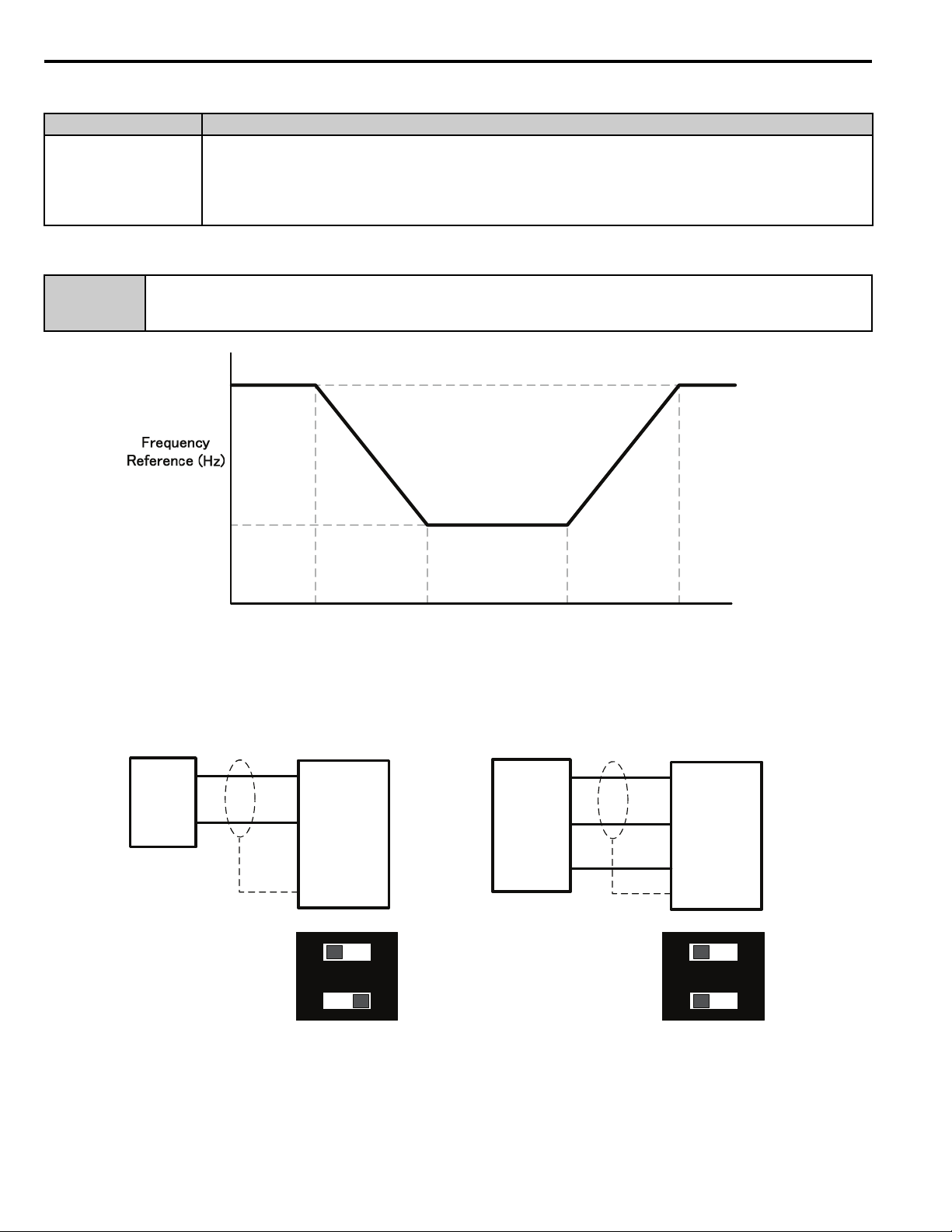
5 Feature Details - Remote Drive Disable
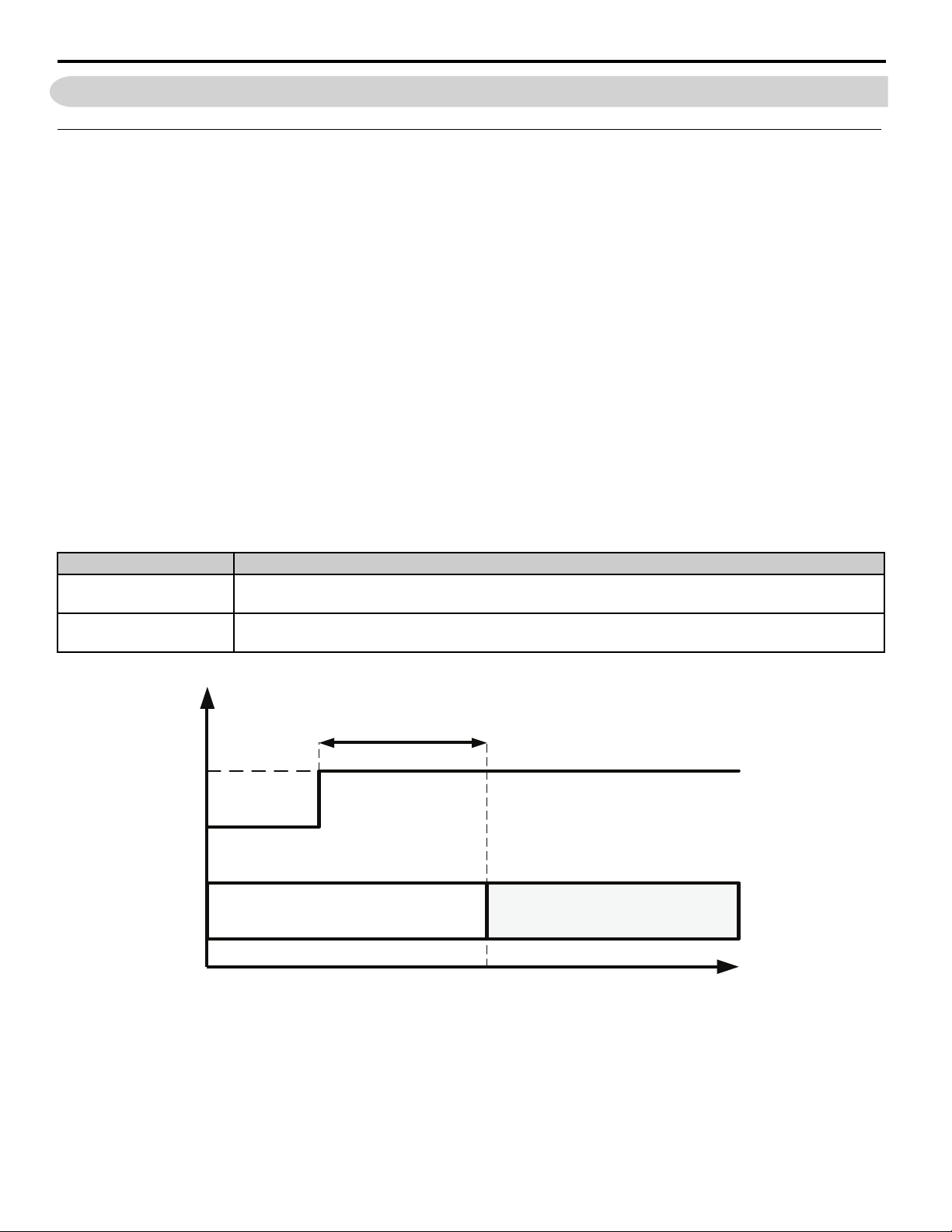
iQpump Drive StoppingiQpump Drive Enabled
Time
Remote
Drive Disable
Active
P4-25 On-Delay Time
Inactive
5 Feature Details - Remote Drive Disable
Overview
This function allows users to prohibit the iQpump Controller from running by using a multi-function digital input set to
"Remote Drv Disbl" (72) in combination with a programmable on time (P4-25) and off time delay (P4-26).
The "Remote Drive Disable" input logic can be selected with parameter P4-24.
Function Operation
When the Remote Drive Disable (H1-0 = 72) input is active for the amount of time specified in P4-25 the drive will be
forced into a sleep-like state. Stopping method used is defined by b1-03 (Stopping Method Selection) setting.
If the iQpump Controller is running as part of a Memobus Network (multiplex system), it will be taken out and
considered unavailable to run.
Alarm "R-DNE-S" will be displayed, where S is the Terminal programmed for Remote Drive Disable (H1-0 = 72).
The iQpump Controller will restart and perform a pre-charge if needed when the Remote Drive Disable ( H1-0 = 72) is
inactive for the time specified in P4-26.
Note: When the drive run is disabled using this feature, the pre-charge function is reset and will run if necessary.
P4-24 Remote Drive Disable Selection
Selects the type of pressure switch connected to the “Remote Drv Disbl” digital input (H1-0 = 72).
Figure 1
Setting Description
0
1
Normally Open (factory default)
Closed indicates a "Remote Disable" condition - active
Normally Closed
Open indicates a "Remote Disable" condition - active
Figure 1 Remote Disable: Inactive to Active Operation
YAS KA WA TM.iQp.10 iQpump Technical Manual Supplement 11
Page 12
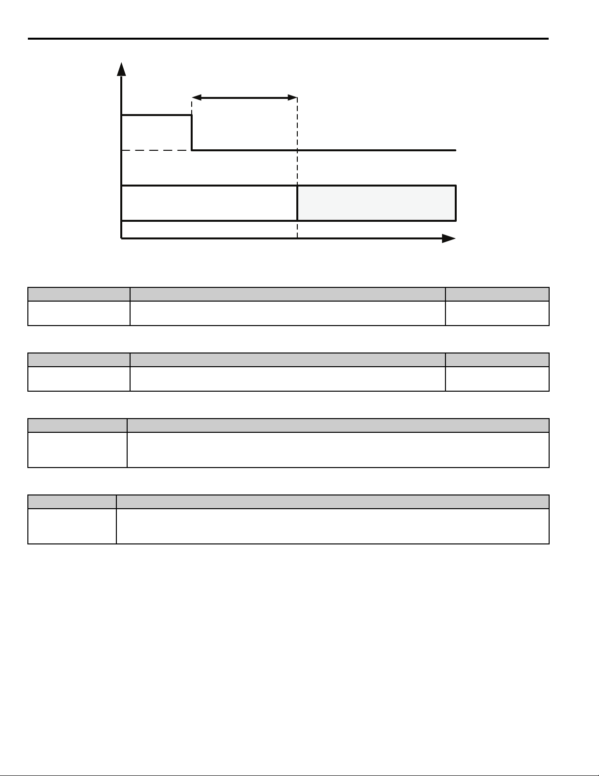
5 Feature Details - Remote Drive Disable
iQpump Drive EnablediQpump Drive Stopped
Time
Remote
Drive Disable
Active
P4-26 Off-Delay Time
Inactive
Figure 2
Figure 2 Remote Disable: Active to Inactive Operation
P4-25 Remote Drive Disable On-Delay Time
Range Description Default
1 - 1000 sec
Sets the amount of time a “Remote Drive Disable” condition needs to be
present before the drive will stop.
0 sec
P4-26 Remote Drive Disable Off-Delay Time
Range Description Default
1 - 1000 sec
Multi-function Input Setting: Remote Drive Disable Function
Setting Description
72 Remote Drv Disbl
Alarm: Remote Drive Disable
Alarm Display Description
R-DNE-Sx
Remote Drv Dis
Note: S or Sx denotes the digital input terminal programmed for this function.
Sets the amount of time a "Remote Drive Disable" condition must be absent
before the drive will be allowed to run.
Remote Drive Disable: Prevents the iQpump Controller from running when active for the time set in
P4-25. Must be inactive for the time set in P4-26 to allow the drive to run again.
Note: Parameter P4-24 determines if this input is Normally Open or Normally Closed.
Multi-function Input Terminal S (H1-0 = 72) has been closed for the time set in P4-25 when P4-24 = 0.
or
Multi-function Input Terminal S (H1-0 = 72) has been open for the time set in P4-25 when P4-24 = 1.
0 sec
12 YASK AWA TM.iQp.10 iQpump Technical Manual Supplement
Page 13

6 Feature Details - Low City Pressure Alarm
6 Feature Details - Low City Pressure Alarm
Overview
The alarm function is used for stopping the iQpump Controller or preventing the iQpump Controller from running based
on an external contact closure.
This function has been enhanced by parameter P4-27 which allows users to select the alarm message that will be
displayed when a Low City Pressure condition is detected.
Function Operation
P4-27 Low City Pressure Alarm Text
Selects the alarm message that will be displayed when a Low City Pressure condition is detected.
Setting Description
0 Low City Pressure (factory default)
1 Low Suction Pressure
2Low Water in Tank
Alarm: Low Pressure/Low Water in Tank
Alarm Display Description
Shown when P4-27 = 1 and when the digital input has been active (closed for P4-21 = 0, or open for
Low Suction Pressure
Low Water In Tank
P4-21 = 1) for the time set in P4-22. The drive, if running, coasts-to-stop and does not run until the digital
input has been inactive for the time set in P4-22.
Shown when P4-27 = 2 and when the digital input has been active
(closed for P4-21 = 0, or open for P4-21 = 1) for the time set in P4-22. The drive, if running, coasts-to-stop
and does not run until the digital input has been inactive for the time set in P4-22.
Related Parameters
P4-21 Low City Pressure Input Select
Setting Description
0 Normally Open (closed for the "Low City Pressure" condition)
1 Normally Closed (open for the "Low City Pressure" condition) (factory default)
P4-22 Low City Pressure Input Delay Time
Range Description Default
Sets the amount of time a "Low City Pressure" condition must be present before
1 - 1000 sec
Multi-function Input Setting H1-: Low City Pressure
Setting Description
73 Low City Pressure
the drives will stop. Also sets the amount of time that the pressure must be
adequate before the drive system will restart.
Indicates that sufficient/insufficient pressure is present on the inlet to the pump. This setting is used mainly
for pressure booster stations.
10 sec
YAS KA WA TM.iQp.10 iQpump Technical Manual Supplement 13
Page 14

7 Suction Control via Constant Pressure w/Well Draw Down
7 Suction Control via Constant Pressure w/Well Draw Down
Overview
This function enables the iQpump Controller to monitor suction pressure at the inlet of the pumps.
Note: This function is active when parameter P8-01 is set to 2 for Suction Control.
Packaged Booster Systems have a desired discharge pressure and a given suction pressure from the city water system or
from a suction tank. Such systems are often designed to handle a specific pressure and flow rate.
The suction pressure may have a wide range between high and low pressures. The suction pressure typically decreases
with increased fluid flow rate. In some instances, pump cavitation may occur if suction pressure falls below a certain
pressure level.
In addition low or negative suction pressure can lead to damage such as pipe collapse due to external forces acting on the
pipe.
The iQpump Controller will accept an analog suction transducer (Terminal A1) and can be programmed to trigger an
alarm or shutdown the system when the suction pressure falls outside of a normal operating range.The iQpump Controller
will automatically restart and return to normal operation once the suction pressure returns to a normal level.
When operating in multiplex mode, additional control can be programmed to de-stage any active pumps as a method to
try and reduce pump loading to prevent suction pressure from continuing to drop below the shut down level.
Function Description
The iQpump Controller will regulate outlet pressure of the pump system using the standard iQpump Controller features
when there is adequate suction pressure available at the inlet of the pumps and offers two options to respond to a drop in
suction pressure.
1. Regulate Outlet Pressure and Suction Pressure: (P8-03 > or = P8-04)
To regulate suction pressure set the suction pressure setpoint (P8-03) to a value greater or equal than the minimum
suction pressure (P8-04). In this mode the iQpump Controller will try to regulate the suction pressure based on the
programmed suction pressure setpoint (P8-03) level.
As the suction pressure decreases and approaches the suction pressure setpoint level (P8-03), the iQpump Controller
will slow down causing the outlet pressure and flow to decrease. When the suction pressure rises above the P8-05 level
for more than the P1-05 time, normal operation (outlet pressure regulation) will resume.
When the suction pressure drops below Minimum Suction Pressure (P8-04), for more than the Sleep Delay Time
(P2-03), the iQpump Controller will go to sleep.
Note: The Suction Control Minimum Speed parameter (P8-06) should be set to a high enough value that will ensure flow.
2. Regulate Outlet Pressure Only: (P8-03 < P8-04)
Set the suction pressure setpoint (P8-03) to a value smaller than the minimum suction pressure (P8-04) to regulate
outlet pressure.
This mode allows the iQpump Controller to maintain the outlet pressure setpoint using the standard iQpump Controller
features and go to sleep immediately when the suction pressure drops below the Minimum Suction Pressure (P8-04),
for more than the Sleep Delay Time (P2-03).
Normal operation (outlet pressure regulation) will resume when the suction pressure returns above the P8-05 level for
more than the P1-05 time.
14 YAS KAWA TM.iQp.10 iQpump Technical Manual Supplement
Page 15

7 Suction Control via Constant Pressure w/Well Draw Down
Duplex System Example
A pump system consisting of a duplex domestic pressure booster system using a pressured city supply averaging 40
Example:
Pump System Settings
• All pumps have the same flow rate and will alternate
• Lag Pump will track speed of lead pump
• All drives have individual discharge transducers rated 150 psi. Upon failure, system will look to network for feedback
information.
• Suction Transducer is rated 75 psi
• Below 40 psi city pressure the pump system will start to reduce speed until reaching 30 psi
• System Auto setpoint 85 psi, with a 5 psi start level.
Duplex System Example (Related Parameters)
- 60 psi. If city pressure starts to fall below 40 psi the pump system will start to slow down to reduce the chances of
pump cavitation. When suction pressure (city pressure) drops to 30 psi, the pump system will shut down (sleep) and
wait until city pressure returns, after which the system will automatically start and operate under normal condition.
Parameter Description Booster Pump 1 Booster Pump 2
H3-02 Terminal A1 Gain 231.3% 231.3%
H3-03 Terminal A1 Bias -25.0% -25.0%
H3-08 Terminal A2 Signal 2 2
H5-01 Drive Node Network Address 1 2
P1-01 Pump Mode 3 3
P1-03 FD Device Scaling 150 psi 150 psi
P1-04 Start Level -5.0 psi -5.0 psi
P8-01 WtrLvl/SuctionPres Selection 2 2
P8-02 Suction Transducer Scaling 75 psi 75 psi
P8-03 Suction Pressure Setpoint 40.0 psi 40.0 psi
P8-04 Minimum Suction Pressure 30.0 psi 30.0 psi
P8-05 Wakeup Suction Pressure 40.0 psi 40.0 psi
P9-02 Feedback Source 2 2
P9-05 Lag Drive Mode 2 2
P9-25 Highest Node Address 3 3
P9-50 Suction Pressure Source 2 2
U1-01 Auto Setpoint 85 psi 85 psi
Note: In multiplex mode the network signal for suction pressure can be used. Refer to Transducer Wiring using an External Power
Supply on page 48.
YAS KA WA TM.iQp.10 iQpump Technical Manual Supplement 15
Page 16

7 Suction Control via Constant Pressure w/Well Draw Down
Enabling Suction Pressure Control
The suction pressure control selection is added to parameter P8-01 Water Level/Suction Pressure Selection. Follow these
steps for basic suction pressure control setup:
1. Enable suction control by setting parameter P8-01 to 2 (Suction Control).
2. Set suction transducer scaling (P8-03) in psi, scaling for analog input A1 (20 mA scale).
3. Set suction pressure setpoint (P8-03) in psi.
4. Select iQpump operation when a drop in suction pressure occurs:
a. Regulate outlet pressure only and go to sleep immediately when suction pressure falls below minimum suction
pressure level (P8-04). Set suction pressure setpoint (P8-03) below minimum suction pressure level (P8-04).
b. Regulate suction pressure when pressure is below suction pressure setpoint (P8-03) but above the minimum
suction pressure level (P8-04). Set suction pressure setpoint (P8-03) to above the minimum suction pressure level
(P8-04).
5. Set minimum suction pressure (P8-04) – Sleep Level for Suction Control.
6. Set suction pressure wake-up level (P8-05) – Wake-up level.
7. Set suction control minimum speed (P8-06) – Minimum Flow Speed.
P8-01 Water Level/Suction Pressure Selection
Sets the mode of operation for the Water Level / Suction Control function.
Setting Description
0 Disabled (factory default)
1
2 Suction Pressure Control (New)
Note: The iQpump Controller will only perform the outlet pressure and suction pressure control when "normal" PI mode is enabled
(b5-01 > 0, not jogging, not disabled via MFDI, etc.).
P8-02 Suction Transducer Scaling
Water Level Control
(This function is defined as "Enabled" for iQpump software PRG: 0034)
Terminal A1 is used for the suction pressure analog input. The analog pressure sensor, mounted on the inlet side of the
pump(s) will provide the required signal. Set this parameter to the full-scale pressure of the transducer. The suction
pressure will then be displayed on the U1-98 monitor.
Range Description Default
5 - 500 psi
P8-03 Suction Pressure Setpoint
Range Description Default
0.0 - 1200.0 psi
P8-04 Minimum Suction Pressure
Sets the full scale (20 mA) output of the pressure transducer connected to
Terminal A1.
Sets the amount of suction pressure the iQpump Controller will attempt to
regulate.
100 psi
20.0 psi
Range Description Default
0.0 - 1200.0 psi
16 YASK AWA TM.iQp.10 iQpump Technical Manual Supplement
When the suction pressure drops to below this level for more than the P2-03
time, the drive will go to sleep and turn off all lag pumps.
10.0 psi
Page 17

7 Suction Control via Constant Pressure w/Well Draw Down
P8-05 Wake-Up Suction Pressure
Range Description Default
If the drive is forced to sleep based upon the minimum suction pressure
0.0 - 1200.0 psi
P8-06 Suction Control Minimum Speed
Range Description Default
0.00 - 120.00 Hz
P8-07 Low Suction Pressure Detection Level <1>
Range Description Default
0.0 - 1200.0 psi
(P8-04), the suction pressure must go above this level for more than the P8-13
time in order to wake up.
This parameter sets the minimum speed the drive will run when the drive is
controlling suction pressure. When the drive is controlling outlet pressure or
this parameter is set less than P1-06 and P4-05, P1-06 and P4-05 will be used as
the minimum speed.
When the amount of suction pressure drops below this level for more than the
P8-08 time, the drive will respond depending on the P8-09 setting. A setting of
0.0 disables this detection.
30.0 psi
0.00 Hz
0.0 psi
P8-08 Low Suction Pressure Detection Time
<1>
Range Description Default
0.0- 300.0 min
Sets the amount of time delay that the suction pressure must drop below the
P8-07 level before the drive will react. *Time units are defined by P8-14.
0.1 min
P8-09 Water Level/Suction Pressure Selection
Sets how the drive will respond when the water level in the well drops below the P8-07 level for more than the P8-08
time.
Setting Description
0 No Display (Digital Output Only)
1 Alarm Only (factory default)
2Fault
3 Auto-Restart (time set by P8-12) (New)
P8-10 Suction Control Proportional Gain
Range Description Default
0.00 - 25.00 Sets the proportional gain for the suction pressure control. 2.00
P8-11 Suction Control Integral Time
Range Description Default
0.0 - 360.0 sec
Sets the integral time for the suction pressure control. A setting of zero disables
the suction pressure control integrator.
5.0 min
P8-12 Suction Control Auto-Restart Time
Range Description Default
0.1 - 6000.0 min
<1>
Low Level/Low Suction Detection (P8-07/P8-08): This feature is disabled when the drive is in Run-Stop control
(b1-02 = 5, Timed Run).
YAS KA WA TM.iQp.10 iQpump Technical Manual Supplement 17
Sets the amount of time the drive will wait before attempting an auto-restart of
the "Low Suction" fault. Effective only when P8-09 = 3 and L5-01 > 0.
5.0 min
Page 18

7 Suction Control via Constant Pressure w/Well Draw Down
P8-13 Suction Pressure Sleep Wake-Up Time
Range Description Default
If the iQpump Controller has been forced to sleep based upon the minimum
0 - 3600 sec
P8-14 Low Suction Pressure Detection Time Unit
suction pressure (P8-04), the pressure must go above the P8-05 level for more
than this time in order to wake up.
1 sec
Defines the time unit for P8-08.
Setting Description
0 Minutes (factory default)
1 Seconds
Suction Pressure Transducer Wire-break Detection
Wire-break detection is active on Terminal A1 when PI Feedback Loss Detection is enabled (b5-12 = 1 or 2) , Suction
control is enabled (P8-01 = 2) and PI control is NOT disabled via Multi-Function Digital Input.
The iQpump Controller detects a wire-break condition when the suction transducer signal on Terminal A1 falls below -
6.25 % or rises above 106.25 % for more than 1 second and will react according to parameter b5-12 (Feedback Loss
Detection).
Note: Wire-break detection on Terminal A1 detection is checked after the gain/bias parameters (H3-02 and H3-03) are applied.
Fault: Low Suction
Fault Display Description
LOSUC
Low Suction
Low Suction: Suction pressure is below the P8-07 level for more than the P8-08 time.
Parameters P8-12 to P8-14 are also available for Water Level control P8-01 set to 1. The parameter titles change
accordingly.
P8-12 Water Level Auto-Restart Time
Range Description Default
Sets the amount of time the iQpump Controller will wait before attempting an
0.1 - 6000.0 min
P8-13 Water Level Sleep Wake-Up Time
Range Description Default
0 - 3600 sec
P8-14 Low Water Detection Time Unit
auto-restart of the "Low Water" fault. Effective only when P8-09 = 3 and
L5-01 > 0.
If the iQpump Controller is forced to sleep based upon the minimum water
level (P8-04), the pressure must go above the P8-05 level for more than this
time in order to wake up.
5.0 min
1 sec
Setting Description
0 Minutes (factory default)
1 Seconds
Multi-function Output Setting H2-: Low Suction (Modified)
Setting Description
This output will energize if P8-01 = 1 and the level in the well drops below the Low Level Detection Level
57 Low Water
18 YASK AWA TM.iQp.10 iQpump Technical Manual Supplement
(P8-07) for more than the Low Level Detection Delay Time (P8-08), or if there is a LOWWL - Low Water
Level Fault.
Page 19

7 Suction Control via Constant Pressure w/Well Draw Down
Multi-function Output Setting H2-: Low Suction (New)
Setting Description
This output will energize if P8-01 = 2 and the suction pressure drops below the Low Suction Pressure
58 Low Suction
Detection Level (P8-07) for more than the Low Suction Pressure Delay Time (P8-08), or if there is a
LOSUC - Low Suction Pressure Fault.
Related Parameters
When P1-01 = 3 (Memobus Multiplex), the Water Level or Suction Pressure can be transmitted or read through the
network. Refer to Water Level/Suction Pressure Control in Memobus Multiplex on page 26.
P9-50 Water Level Source (P8-01 set to 0 or 1, Water Level Control)
Defines which signal to use for Water Level Control (P8-) when P1-01=3.
Setting has no effect when P1-01≠3.
Setting Description
0 Analog Only (factory default)
1 Analog -> Network, No Alarm
2 Analog -> Network, Alarm
3 Network Only
P9-50 Suction Pressure Level Source (P8-01 set to 2 Suction Control)
Defines which signal to use for Suction Pressure Control (P8-) when P1-01=3.
Setting has no effect when P1-01≠3.
Setting Description
0 Analog Only (factory default)
1 Analog -> Network, No Alarm
2 Analog -> Network, Alarm
3 Network Only
YAS KA WA TM.iQp.10 iQpump Technical Manual Supplement 19
Page 20
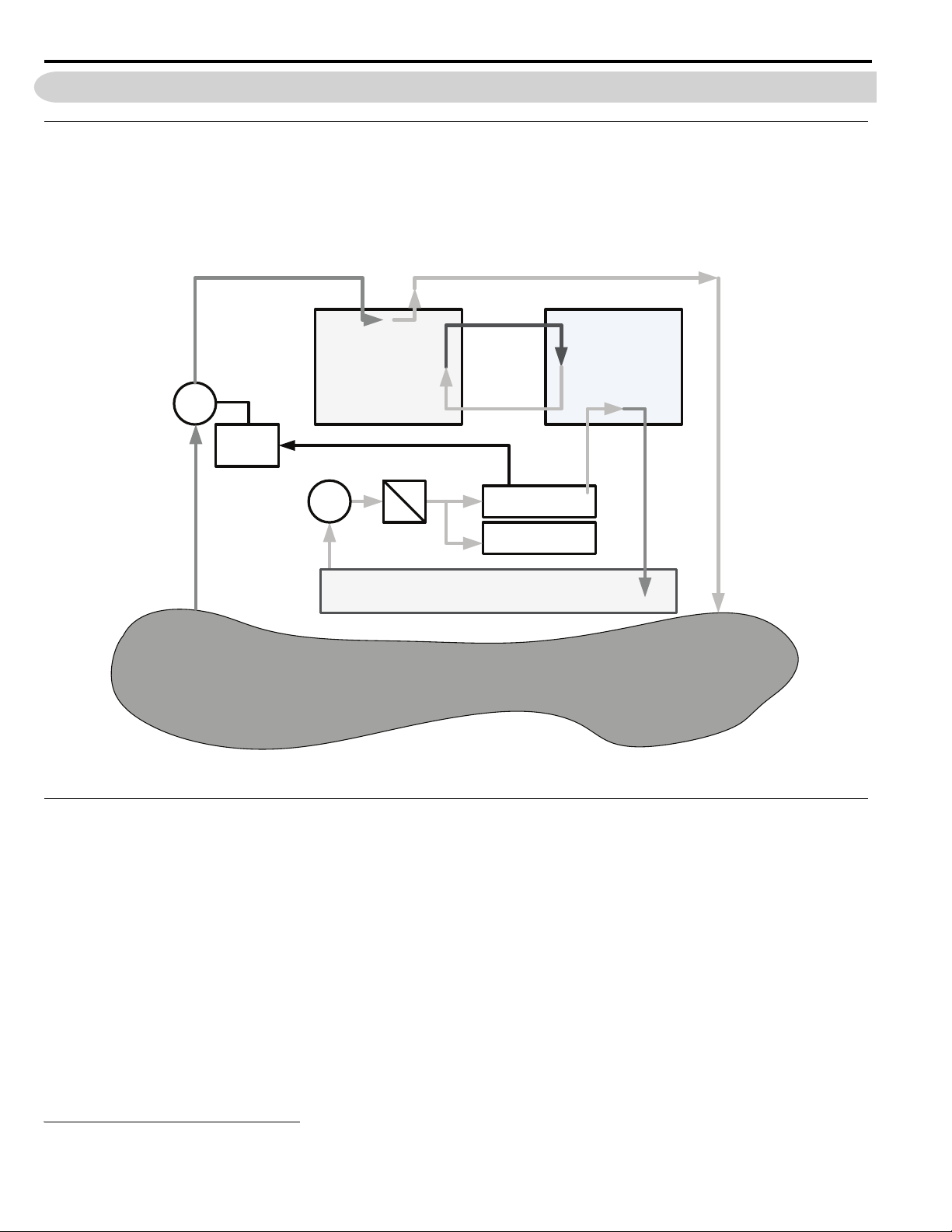
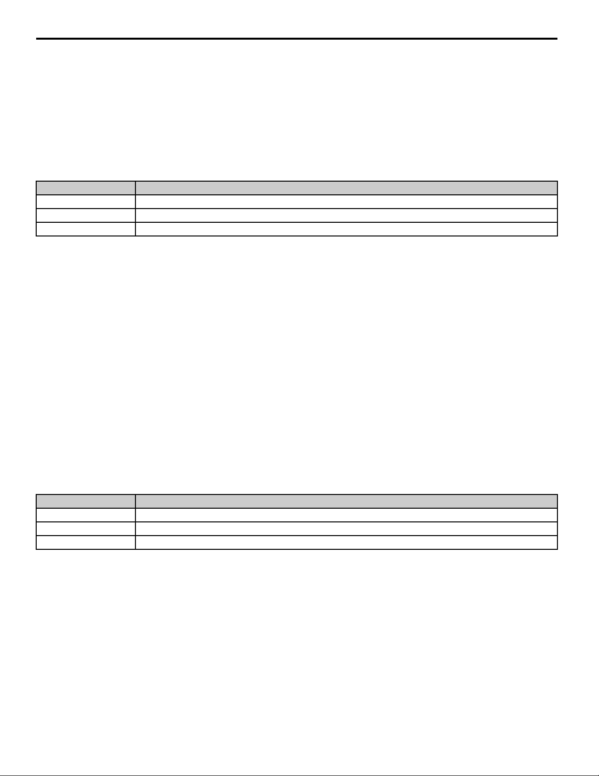
8 Geothermal Mode
Aquifer
Heat
Exchanger
iQpump
Geothermal
Heater
Thermostat
Pool
M
Discharge Valve
Pool
Pump
Filter
M
Well
Pump
Discharge
Well
Warm Cold
Cold
Warm
Cold
Warm
Warm
Cold
Cold
8 Geothermal Mode
Overview
A geothermal well facilitates heat transfer between the earth and a known system, such as space heating, dehydration,
electric power generation and food processing.
The geothermal function has the ability to regulate the speed of the iQpump Controller based on an external temperature
signal following a preset temperature-speed curve.
Figure 3
Figure 3 Geothermal Pool Application
Geothermal Mode Setup Procedure
Follow these steps to setup the iQpump Controller in Geothermal Mode:
1. Set iQpump Controller parameters to factory default by setting parameter A1-03 to 2220 for "2 Wire" Initialization.
2. Disable PI Control by setting parameter b5-01 to 0 "Disabled"
3. Set multi-function analog input function H3-09 to 20 "Geothermal Temp"
4. Enable Geothermal Mode by setting parameter b1-01 to 5 "Geothermal Mode"
5. Set display monitor to selectable mode by setting o1-06 to 1 "3 Mon Selectable"
6. Select monitor display line #1 to display output frequency by setting o2-01 to 2 "Output Freq"
7. Select monitor display line #3 to display temperature by setting o1-08 to 80 "Geothermal Temp"
8. Set the temperature transducer range to properly scale the input. (P4-31 and P4-32)
9. Set the temperature-speed curve to the intended operation (P4-33 ~ P4-38)
<1>
"3330" for 3-Wire Initialization or "7770" for General Purpose Initialization can also be used.
20 YAS KAWA TM.iQp.10 iQpump Technical Manual Supplement
<1>
Page 21

Related Parameters
b1-01 Frequency Reference Source Selection
Set the frequency reference source (b1-01) to 5 for Geothermal mode operation.
Setting Description
0 Operator - Digital preset speed d1-01 (factory default)
1 Terminals - Analog input Terminal A1 (or Terminal A2, see parameter H3-13)
2 Serial Com - RS-485 terminals R+, R-, S+ and S-
3 Option PCB - Option board connected at 2CN
5
Geothermal Mode - Frequency reference is dependent on temperature input
(H3-09 = 20) <0035>
H3-09 Multi-function Analog Input Setting: Geothermal Temperature
Program H3-09 = 20 to use an external temperature sensor in Geothermal mode operation.
Setting Description
Geothermal Temperature
20
Analog input function for use with an external temperature sensor.
Range scaling: 0V (or 4 mA) = P4-31 ~ 10 V (or 20 mA) = P4-32
8 Geothermal Mode
Geothermal Mode Frequency/Temperature Characteristic
When the iQpump Controller is set to operate in Geothermal Mode (b1-01 = 5), the drive's frequency reference is
determined by the analog input Geothermal Temperature (H3-09 = 20) and the setting of parameters P4-33 ~ P4-38. The
Geothermal characteristic can be programmed in normal or inverse operation.
Normal Operation: P4-33 < P4-34 and P4-35 < P4-36 < P4-37 < P4-38
Inverse Operation: P4-33 > P4-34 and P4-35 < P4-36 < P4-37 < P4-38
P4-31 Minimum Geothermal Temperature Input
Range Description Default
-110.0 ~ 440.0 °F Sets the temperature that corresponds to a 0V (or 4 mA) analog input. 0.0 °F
P4-32 Maximum Geothermal Temperature Input
Range Description Default
-110.0 ~ 450.0 °F Sets the temperature that corresponds to a 10V (or 20 mA) analog input. 150.0 °F
YAS KA WA TM.iQp.10 iQpump Technical Manual Supplement 21
Page 22
8 Geothermal Mode
Maximum
Geothermal Speed
㩿㪧㪋㪄㪊㪋㪀
Minimum
Geothermal Speed
㩿㪧㪋㪄㪊㪊㪀
Low Temp
@ Max
㩿㪧㪋㪄㪊㪌㪀
Low Temp
@ Min
㩿㪧㪋㪄㪊㪍㪀
Temperature (°F)
High Temp
@ Min
㩿㪧㪋㪄㪊㪎㪀
High Temp
@ Max
㩿㪧㪋㪄㪊㪏㪀
Maximum
Geothermal Speed
㩿㪧㪋㪄㪊㪋㪀
Minimum
Geothermal Speed
㩿㪧㪋㪄㪊㪊㪀
Low Temp
@ Max
㩿㪧㪋㪄㪊㪌㪀
Low Temp
@ Min
㩿㪧㪋㪄㪊㪍㪀
Temperature (°F)
High Temp
@ Min
㩿㪧㪋㪄㪊㪎㪀
High Temp
@ Max
㩿㪧㪋㪄㪊㪏㪀
Parameter No. Parameter Name Description Range Default
Sets the frequency reference characteristics based on the set
P4-33 Minimum Geothermal Speed
temperature points and the corresponding frequency.
For proper operation, P4-34 > P4-33 and P4-38 > P4-37 > P4-36 >
P4-35.
0.00 ~
120.00 Hz
40.00 Hz
P4-34 Maximum Geothermal Speed
P4-35
P4-36
P4-37
P4-38
Low Temperature to Run at
Maximum Geothermal Speed
Low Temperature to Run at
Minimum Geothermal Speed
High Temperature to Run at
Minimum Geothermal Speed
High Temperature to Run at
Maximum Geothermal Speed
Geothermal Mode Frequency/Temperature Characteristic|
(Normal Operation)
.
Geothermal Mode Frequency/Temperature Characteristic
(Inverse Operation)
0.00 ~
120.00 Hz
-110.0 ~
450.0 °F
-110.0 ~
450.0 °F
-110.0 ~
450.0 °F
-110.0 ~
450.0 °F
40.00 Hz
55.0 °F
65.0 °F
75.0 °F
85.0 °F
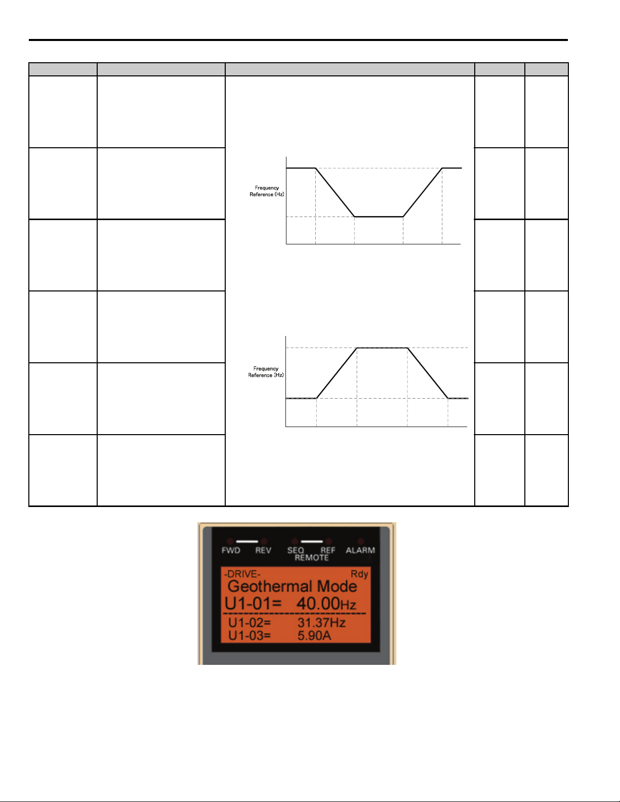
Figure 4
22 YASK AWA TM.iQp.10 iQpump Technical Manual Supplement
Figure 4 Digital Operator Display Showing Geothermal Mode Operation
Page 23

8 Geothermal Mode
Geothermal Mode iQpump Controller Monitors
U1-80 Geothermal Temperature Input
Unit Description
0.1 °F
Note: Only shown when b1-05 = 5 (Geothermal Mode)
Displays Geothermal temperature input after gain and bias are applied. This is the temperature used by the
Geothermal Function to determine what frequency to run the iQpump Controller.
Geothermal Temperature Loss Detection
P4-39 Geothermal Temperature Loss Detection
Selects iQpump Controller action when the temperature sensor signal from Terminal A2 is below 3 mA or above 21 mA.
Setting Description
0Disabled
1 Alarm (factory default)
2Fault
Note: Only effective when H3-08 = 2 (4-20 mA) and H3-09 = 20 (Geothermal Temp).
Alarm: Temperature Sensor Lost (factory default)
Alarm Display Description
The geothermal temperature sensor is not present. Alarm occurs when:
1. b1-01 = 5, H3-09 = 20 (Geothermal Temp), H3-08 = 2 (4-20 mA), P4-39 = 1 (Alarm), and the input has
either dropped below 3 mA or went above 21 mA.
Check: Ensure the device connected to Terminal A2 is installed and working properly.
2. b1-01 = 5, and H3-09 ≠ 20 (Geothermal Temp), and P4-39 = 1 (Alarm).
Tem p Lo s t
Geothermal Input
Alarm: Geothermal Parameters Programming Error
Alarm Display Description
Geo Params
Check P4-35~P4-38
Fault: Temperature Sensor Lost
Fault Display Description
Tem p Lo s t
Geothermal Input
Check: Terminal A2 must be assigned to Geothermal Temp (H3-09 = 20).
3. b1-01 = 5, H3-09 = 20 (Geothermal Temp), H3-08 = 2 (4-20 mA), P4-39 = 2 (Fault), the drive is either
in HAND mode or has no run command, and the input is below 3 mA or above 21 mA.
Check: Ensure the device connected to Terminal A2 is installed and working properly.
4. b1-01 = 5, and H3-09 ≠ 20 (Geothermal Temp), P4-39 = 2 (Fault), and the drive is either in HAND mode
or has no run command.
Check: Terminal A2 needs to be assigned to Geothermal Temp (H3-09=20).
The drive is running at the P4-31 level because of an incorrect setting.
The temperature parameter values must be set in the following order:
P4-35 < P4-36 < P4-37 < P4-38
The geothermal temperature sensor is not present. Fault occurs when:
1.b1-01 = 5, and H3-09 ≠ 20 (Geothermal Temp), and P4-39 = 2 (Fault).
Check: Terminal A2 must be assigned to Geothermal Temp (H3-09 = 20).
2.b1-01 = 5, H3-09 = 20 (Geothermal Temp), H3-08 = 2 (4-20 mA), P4-39 = 2 (Fault), the drive is either in
HAND mode or has no run command, and the input is below 3 mA or above 21 mA.
Check: Ensure the device connected to Terminal A2 is installed and working properly.
YAS KA WA TM.iQp.10 iQpump Technical Manual Supplement 23
Page 24
8 Geothermal Mode
60Hz
㩿㪧㪋㪄㪊㪋㪀
35Hz
㩿㪧㪋㪄㪊㪊㪀
55°F
㩿㪧㪋㪄㪊㪌㪀
65°F
㩿㪧㪋㪄㪊㪍㪀
Temperature (°F)
75°F
㩿㪧㪋㪄㪊㪎㪀
85°F
㪧㪋㪄㪊㪏㪀
Output
Temperature
Transducer
V+
A2
AC
+V
EG
iQpump
Output
V+
A2
AC
+V
EG
iQpump
Common
4-20mA
Temperature
Transducer
0-10V
Set S1-2 to OFF
O
F
F
1
2
Set S1-2 to ON
* Factory Default
O
F
F
1
2
Set parameter H3-08
Terminal A2 Signal to ‘0’
for 0 – 10V.
Fault: Geothermal Frequency Reference/Temperature Curve Error: OPE19
Fault Display Description
Parameter selection is not compatible with the Geothermal Mode (b1-01 = 5) setting. Fault occurs when
OPE19
Geothermal Set
b1-01 = 5 (Geothermal Mode), and one of the following is NOT set:
- b5-01 = 0 (PI Disabled)
- P1-01 = 0 (Simplex)
Check: Confirm parameter settings for b1-01, b5-01, and P1-01.
Example: Geothermal Pump System Transducer Setup
Geothermal Pump system using a temperature transducer 4 - 20 mA with a temperature range of 0 - 120 °F. The
Example:
system requires a minimum pump speed of 35 Hz. The system requires increased pump speed when the temperature
increases above 75 °F or when temperature falls below 65 °F.
Geothermal Mode Setup Procedure:
Refer to Geothermal Mode Setup Procedure on page 20 for steps to setup the iQpump Controller for Geothermal Mode.
24 YASK AWA TM.iQp.10 iQpump Technical Manual Supplement
Page 25

8 Geothermal Mode
Related Parameters for Geothermal Mode Operation
Parameter Description iQpump Controller
b1-01 Frequency Reference Source 5
b5-01 PI Mode 0
H3-09 Terminal A2 Function Selection 20
o1-06 User Monitor Selection Mode 1
o1-02 <1>
o1-08 Third Line User Monitor Selection 80
P1-01 Pump Mode 0
P4-31 Minimum Geothermal Temperature Input 0.0 °F
P4-32 Maximum Geothermal Temperature Input 120.0 °F
P4-33 Minimum Geothermal Speed 35.00 Hz
P4-34 Maximum Geothermal Speed 60.00 Hz
P4-35 Low Temperature to Run at Max. Geothermal speed 55.0 °F
P4-36 Low Temperature to Run at Min. Geothermal speed 65.0 °F
P4-37 High Temperature to Run at Min. Geothermal speed 75.0 °F
P4-38 High Temperature to Run at Max. Geothermal speed 85.0 °F
P4-39 Geothermal Temperature Loss Detection 1
<1> After programming is completed, cycle power to the drive, as changes to the o1-02 monitor requires a drive power-up cycle to be effective.
User Monitor Selection After Power-Up 2
YAS KA WA TM.iQp.10 iQpump Technical Manual Supplement 25
Page 26

9 Water Level/Suction Pressure Control in Memobus Multiplex
9 Water Level/Suction Pressure Control in Memobus Multiplex
Overview
When using Water Level or Suction Pressure Control in a Memobus Multiplex system, (see parameter P8-01). The
iQpump Controller can be programmed to receive the Water Level or Suction Pressure information from another drive on
the network with a Water Level or Suction Pressure input.
Parameters
Parameter representation for this function depends on the setting of parameter P8-01.
Parameter Settings
P8-01 Water Level/Suction Pressure Selection
Setting Description
0 Disabled (factory default)
1 Water Level Control (Previous version PRG: 0034 functionality for setting is "Enabled")
2 Suction Pressure Control
P9-50 Water Level Source (P8-01 set to 0 or 1, Water Level Control)
Setting Description
0 Analog Only (factory default)
1 Analog -> Network, No Alarm
2 Analog -> Network, Alarm
3Network Only
P9-50 Suction Pressure Level Source (P8-01 set to 2 Suction Pressure Control)
Setting Description
0 Analog Only (factory default)
1 Analog -> Network, No Alarm
2 Analog -> Network, Alarm
3Network Only
P9-50 = 0 (Analog Only)
This drive will transmit its Water Level/Suction Pressure signal to the network. If this signal is lost, the drive will not
switch to another signal on the network. The detection action in this mode is solely on parameter b5-12.
P9-50 = 1 (Ana->Net, No Alarm)
This drive will transmit its Water Level/Suction Pressure signal to the network when the analog input is healthy. If this
signal is lost, the drive will switch to another signal on the network if available. If there are no available network signals,
then this drive will act according to the setting of parameter b5-12 (when = 1 or 2).
Note: Setting parameter b5-12 to 0 will disable analog feedback detection and will prevent the iQpump Controller from switching to the
Network Water Level/Suction Pressure.
P9-50 = 2 (Ana->Net, Alarm)
This drive will transmit its Water Level / Suction Pressure signal to the network when the analog input is healthy. If this
signal is lost, the drive will switch to another signal on the network if available. An alarm will be displayed indicating that
the analog signal has been lost and that the signal is coming from the network. If there are no available network signals,
then this drive will act according to the setting of parameter b5-12 (when = 1 or 2).
Note: Setting parameter b5-12 to 0 will disable analog feedback detection and will prevent the iQpump Controller from switching to the
Network Water Level/Suction Pressure.
26 YAS KAWA TM.iQp.10 iQpump Technical Manual Supplement
Page 27
9 Water Level/Suction Pressure Control in Memobus Multiplex
P9-50 = 3 (Network Only)
The drive will always use a valid network Water Level / Suction Pressure signal. If there are no available network signals,
the drive will act according to the setting of b5-12 with the following differences:
Setting b5-12 to 1: Instead of an alarm, Network P8- Lost message is displayed.
Setting b5-12 to 2: Instead of a fault, Network P8- Lost message is displayed. In this condition the iQpump
Controller no longer accepts iQpump Controller Network run commands and the stopping method is fixed to coast-tostop.
b5-12 PI Feedback Reference Missing Detection Selection
Setting Description
0Disabled
1Alarm
2 Fault (factory default)
Any drive with b5-12 set to 0 (Disabled) and P9-50 ≠ 3 will effectively have no Terminal A1 signal loss detection and
will continuously send the Water Level/Suction Pressure to the iQpump Controller Network regardless of a faulty or an
invalid signal.
When b5-12 set to 2 (Fault) and P9-02 = 3, iQpump Controller will display a feedback loss alarm instead of a fault when
one of the following conditions active:
1. The iQpump Controller is in Hand Mode
2. There is no Lead iQpump Controller on the network
3. The iQpump Controller is not in Auto Mode
Minimum Water Level or Suction Pressure Detection Operation
In case of a minimum water level or suction pressure, the lead iQpump Controller will de-stage when one or more Lag
iQpump Controllers are present, otherwise the lead iQpump Controller will go to sleep.
Note: Setting parameter b5-12 to 0 will disable analog feedback detection and will prevent the iQpump Controller from switching to the
Network Water Level/Suction Pressure.
Related Parameters
b5-12 PI Feedback Reference Missing Detection Selection
Setting Description
0 Disabled (factory default)
1Alarm
2Fault
YAS KA WA TM.iQp.10 iQpump Technical Manual Supplement 27
Page 28

9 Water Level/Suction Pressure Control in Memobus Multiplex
P2-03 Sleep Delay Time
Sets delay time when water level or suction pressure signal falls below the minimum level programmed (P8-04).
Range Description
Network Multiplex Mode: Water Level Control (P8-01 = 1): Parameter specifies the time delay before
the lead drive de-stages when the water level (U1-98) falls below the Minimum Water Level (P8-04).
Network Multiplex Mode: Suction Control (P8-01 = 2): Parameter specifies the time delay before the
0 - 3600 sec
Default: 5 sec
lead drive de-stages when the suction pressure (U1-98) falls below the Minimum Suction Pressure (P8-
04).
Contactor Multiplex Mode (P1-01 =1 or 2): There are two contactor multiplex modes, one for Water
Level and another for Suction. Contactors programmed for Multiplex (H2- = 40 and 41) will open
one by one when the Water Level (U1-98) is below the Minimum Water Level (P8-04) for the time set in
the Sleep Delay Time (P2-03).
IMPORTANT: Staging Restriction when in Water Level/Suction Pressure Control.
• When P1-01 = 3 (Memobus Network) and the iQpump Controller’s PI output is being influenced by the Water Level/
Suction Pressure Control, pump system staging is disabled.
• When P1-01 = 1 or 2 (Multiplex system) and the iQpump Controller’s PI output is being influenced by the Water Level/
Suction Pressure Control, Multi-function output contacts (H2- = 40 and 41) are prohibited from closing.
Alarm: Water Level/Suction Pressure Transducer Lost
Alarm Display Description
Analog Terminal A1 signal is lost and the Network Water Level or Suction Pressure signal is now used.
AnalogA1 Lost
Switched to Net
Alarm: Network Water or Suction Pressure Signal Lost
Alarm Display Description
Net Wtr/Suctn
Lost, Chk Source
Fault: Programming Error: OPE13 Terminal A1
Fault Display Description
OPE13
Terminal A1
Cause: Defective or broken analog input source.
Countermeasure: Check to ensure the Water Level or Suction Pressure source is installed and working
properly. If no signal is present, set P9-50 = 3 to have it always read from another drive's network Water
Level or Suction Pressure.
Network source for Water Level or Suction Control Pressure is lost.
Cause: Valid analog source for Water Level or Suction Control Pressure can not be found on the network.
Countermeasure: Check the source on drives configured as P9-50 ≠ 3.
Cause: Terminal A1 is assigned to more than one of the following functions.
• Frequency Reference (b1-01 = 1)
• Dual Zone PI is enabled (b5-01 = 2)
• Flow Meter Enabled (P6-01 > 0)*
• Water Level/Suction Pressure Control Enabled (P8-01>0)*
• Hand Mode Ref Term A1 (P5-01 = 0)
Note: An OPE13 error will not be generated if b1-01 = 1 and P5-01 = 0, and none of the other conditions
listed above apply.
*When P1-01 = 3 (Memobus), a setting of P6-01 > 0 and P8-01 > 0 is allowed only if P9-40 = 1 or
P9-50 = 3.
Countermeasure: Reprogram b1-01, b5-01, P6-01, or P8-01.
Note: The OPE13 fault is modified in drive software version PRG:0035. Previous software versions have
different functionality.
28 YASK AWA TM.iQp.10 iQpump Technical Manual Supplement
Page 29
10 iQpump MEMOBUS/Network Operation
10 iQpump MEMOBUS/Network Operation
Lag Drive Speed Follower and Lag Turn Off
Certain multiplex pump systems require a common pump speed for all running pumps. To allow for this operation, a new
selection "Follow Lead Spd" is added to parameter P9-05.
Function Description
P9-05 Lag Drive Mode
Setting Description
0
1
2
3
Note: The rate at which the Lag drives follow the Lead drive's output speed is dependent on the communication speed of the iQpump
Controller network (H5-02), the maximum number of iQpump Controllers on the network (P9-25) and the current number of
iQpump Controllers online.
Fixed Speed (factory default)
Runs at the P9-06 setting after the P9-07 time expires.
PI Regulation.
Uses PI to determine speed.
Turn Off
The iQpump Controller stops running when it switches to a lag drive after P9-07 time expires.
Follow Lead Spd
The iQpump Controller follows the speed of the active Lead drive. Use P9-30 gain and P9-31 bias setting
to adjust reference signal.
Display Message for Follow Lead Speed Operation:
When the iQpump Controller is operating in Auto Mode, Lag operation and the Follow Lead Speed function is active
(P9-05 = 3) then the display will show the actual frequency reference in Hz instead of the selected system units.
YAS KA WA TM.iQp.10 iQpump Technical Manual Supplement 29
Page 30

10 iQpump MEMOBUS/Network Operation
Related Parameters
P9-06 Lag Fixed Speed
Range Description Default
0 - 120.0 Hz
P9-07 Lag Fixed Speed Delay
When the drive changes from a lead to a lag and P9-05 = 0, the drive will run at
this speed after P9-07 delay time expires.
Time delay before execution of P9-05 selection when the iQpump Controller changes from lead to lag.
Note: Only active when Lag Mode Selection (P9-05) is set to 0, 2 or 3.
Range Description Default
When the drive changes from a lead to a lag and P9-05 ≠ 1, this time specified
in parameter P9-07 determines how long the speed is latched before executing
0 - 1000 sec
one of the following operations:
1. P9-05 = 0: Run at P9-06
2. P9-05 = 2: Turn off
3. P9-05 = 3: Follow the Lead Drive's speed.
5 sec
New Parameters
P9-30 Lag Follower Gain
55.0 Hz
Range Description Default
0.0 -300.0%
P9-31 Lag Follower Bias
Range Description Default
-60.00 - 60.00 Hz
When P9-05 = 3, the drive will follow the speed of the active lead drive
applying this gain and P9-31 bias to the reference signal.
When P9-05 = 3, the drive will follow the speed of the active lead drive
applying this bias and P9-30 gain to the reference signal.
100.0 %
0.00 Hz
30 YASK AWA TM.iQp.10 iQpump Technical Manual Supplement
Page 31

10 iQpump MEMOBUS/Network Operation
Flow Meter
Outlet
Pressure
Transducer
Inlet
Pump 2 Pump 3
Network
Pump 1
iQpump 2 iQpump 3iQpump 1
A1
A2
4-20mA
0-10V
Flow Pressure
Flow Meter
Certain multiplex pump systems require staging/de-staging based on the flow rate. The iQpump Controller offers a
dedicated set of parameters to operate multiplex pump systems based on flow control.
Multiplex Pump System Operation
Flow Rate Staging: Set P9-08 (Add Pump Mode) to 3: Flow Meter.
This mode monitors the Flow Rate to determine if staging is needed. If the Flow Rate of the lead iQpump Controller rises
above the Flow Staging level (no. of pumps running times P9-41) for the time set in P9-11, the drive will issue a network
stage request if an iQpump Controller is available to run.
If P9-41 Add Flow Rate Level set to 80.0 GPM, then the 2nd pump is called to run when the flow rate rises above
Example:
De-staging: Set P9-12 (Remove Pump Mode) to 3: Flow Meter.
This mode monitors the Flow Rate to determine if de-staging is needed. If the flow rate of the lead iQpump Controller
falls below the Flow De-Staging level ((no. of pumps running - 1) x P9-42) for the time set in P9-15, a de-stage request is
issued if two or more iQpump Controllers are running on the network.
Example:
NOTICE: Using Fixed Speed Lag Drive mode P9-05 = 0 in conjunction with Flow Meter Staging (P9-08 = 3) or Flow Meter De-staging
(P9-12 = 3) could result in an unstable system depending on the system and the parameter settings.
80.0 GPM. The 3rd pump is called to run the flow rate rises above 160.0 GPM and the 4th pump is called when the
flow rate rises above 240.0 GPM.
If P9-42 = 60.0 GPM, then the 4th pump is de-staged when flow rate falls below 180.0 GPM. The 3rd pump is destaged when the flow rate falls below 120.0 GPM (gallons per minute ) and the 2nd pump is de-staged when the
flow rate falls below
60.0 GPM.
YAS KA WA TM.iQp.10 iQpump Technical Manual Supplement 31
Page 32

10 iQpump MEMOBUS/Network Operation
New Parameters
P9-40 Flow Rate Source
Defines the Flow Meter input source when P1-01=3 (Memobus Network).
Setting Description
0 Analog (factory default)
1
P9-41 Add Flow Rate Level
Range Description Default
0.0 ~ 6000.0 <1>
<1> Displayed units are determined by parameter P6-02.
P9-42 Remove Flow Rate Level
Range Description Default
0.0 ~ 6000.0 <1>
<1> Displayed units are determined by parameter P6-02.
Network
Uses PI to determine speed.
When P9-08=3 and the Flow Rate is above this level times (No. of pumps
running) for the time set in P9-11, the lead drive will request for a new lead
drive through the iQpump Controller Memobus network.
When P9-12=3 and the Flow Rate is below this level times (No. of pumps
running minus 1) for the time set in P9-15, the lead drive will request to be
removed from the system through the iQpump Controller Memobus network.
0.0
0.0
Related Parameters
P6-01 Flow Meter Scaling
Range Description Default
Sets the scaling for the flow meter connected to terminal A1. Enter the gal/min
0.0 ~ 6000.0 GPM
P6-02 Water Flow Units
Sets the units displayed for monitor U1-95. Also sets units for parameters P2-02, P6-04, P9-41 and P9-42.
Setting Description
0 U.S. Gallons/min (GPM) (factory default)
1 U.S. Gallons/Hr (GPH)
2 U.S. Barrels/min (BPM)
3 U.S. Barrels/hour (BPH)
4 U.S. Barrels/day (BPD)
P9-08 Add Pump Mode
Selects the detection method for staging a new pump.
Setting Description
0 Output Frequency (factory default)
1 Feedback
2 Feedback + Fout
3Flow Meter (New)
when the flow meter is at its rated output. A setting of 0.0 disables all flow
meter functions.
0.0 GPM
32 YASK AWA TM.iQp.10 iQpump Technical Manual Supplement
Page 33

10 iQpump MEMOBUS/Network Operation
P9-11 Add Delay Time
Range Description Default
0 ~ 3600 sec Delay time before a new lead drive is added to the system. 10 sec
P9-12 Remove Pump Mode
Selects the detection method for de-staging to the previous lead pump.
Setting Description
0 Output Frequency (factory default)
1 Feedback
2 Feedback + Fout
3 Flow Meter
P9-15 Remove Delay Time
Range Description Default
0 ~ 3600 sec Delay time before the lead drive is removed from the system. 10 sec
Alarm: Network Water or Suction Pressure Signal Lost
Alarm Display Description
There is no drive on the Memobus Network with an analog Flow Meter.
Net FlowMeter
Lost, Chk Source
Cause: With P1-01 = 3, P6-01 > 0 and P9-40 = 1 (Network), the Flow Meter function needs a valid Flow
Rate from the network originating from another drive that is also running the Flow Meter function
(P6-01 > 0) with P9-40 = 0 (Analog).
Countermeasure: If the drive has an operational Flow Meter connected to Terminal A1, set P9-40 = 0. If
another drive on the Memobus Network has a Flow meter connected to Terminal A1, confirm that drive is
online, with P6-01 > 0 and P9-40 = 0.
YAS KA WA TM.iQp.10 iQpump Technical Manual Supplement 33
Page 34

10 iQpump MEMOBUS/Network Operation
New Lead Drive Selection: Stop History
Overview
Many irrigation pumping skids consist of a PM pump (Pressure Maintenance) and typically two (2) larger booster pumps
to maintain high flow peak demands.
In many cases depending on the number of irrigation zones in combination with the type of sprinkler heads used, the flow
demand fluctuates and may not require the use of both larger booster pumps at the same time until higher flow rates are
required.
The iQpump Controller "Run Stop" history ensures that both booster pumps alternate each run cycle.
Parameters
P9-01 Lead Drive Selection
Selects the detection method for staging a new pump.
Setting Description
0
1
2
Next Available
Select next available drive on the network as the new lead drive.
Lowest Runtime (factory default)
Select the iQpump Controller with the lowest runtime as the new lead drive.
Stop History
Select the iQpump that had been stopped the longest time.
Note: This new lead drive selection also applies to Alternation (P9-03 > 0) and will use the Stop History list when finding the alternate
drive.
System Example: Triplex Irrigation Booster System-Using Stop History
Overview
A typical pump system operates as described below:
When pressure is dropping, the PM Pump (if installed) will attempt to return the system pressure to the desired setpoint
level. If the PM Pump is not able to return the system to the setpoint pressure, typically due to a greater flow demand, the
first booster pump (1) will be called to start.
The iQpump Controller will speed up or slow down the pump as needed to maintain the system pressure. When flow
decreases and the pump system is no longer required to run, the system will go to sleep waiting for the pressure to drop.
On the next run cycle the PM pump will start up again, and instead of running booster pump #1, booster pump #2 is
started, since booster #1 ran during the last cycle.
This method ensures that during normal operation both booster pumps will operate evenly as lead or lag pumps each run
cycle.
Detailed Description
Triplex irrigation booster system consisting of one PM Pump (pressure maintenance) and two larger booster pumps of the
same horsepower. The customer would like to ensure that the PM Pump is also the lead pump to recharge the system
during low flow usage, but during high demands the booster pumps alternate on each run cycle or if required will both run
to support very high flow demands.
• Jockey/PM Pump will also be lead to start.
• Jockey/PM Pump will stage booster pump 1 or 2 and stay running for 20 seconds and then shut off.
• Booster pump 1 will run system and if required, call for booster pump 2 or vice versa.
• On sleep mode, the lead drive for starting will swap back to Jockey/PM Pump.
• System setpoint 100 psi.
• Pressure drop of 10 psi will start the Jockey pump.
• All drives have individual transducers rated 200 psi maximum, but if there is a transducer failure, switch to network.
34 YASK AWA TM.iQp.10 iQpump Technical Manual Supplement
Page 35

10 iQpump MEMOBUS/Network Operation
Related Parameters: Triplex Irrigation Booster System
Parameter Description PM Pump Booster Pump 1 Booster Pump 2
H5-01 Drive Node Network Address 1 2 3
P1-01 Pump Mode 3 3 3
P1-03 FD Device Scaling 200 psi 200 psi 200 psi
P1-04 Start Level -10.0 psi -10.0 psi -10.0 psi
P9-01 Lead Drive Select 2 2 2
P9-02 Feedback Source 2 2 2
P9-07
P9-20
P9-21 Run Priority 7 8 8
P9-24 Lead Swap @ Sleep 0 sec 1 sec 1 sec
P9-25 Highest Node Address 3 3 3
U1-01 Auto Setpoint 100 psi 100 psi 100 psi
Lag Fixed Spd Dly
(PM Pump will shut off after 20 sec)
Allow Net Run
(PM Pump will be lead Pump to start)
20 sec 5 sec 5 sec
200
Network
Transducer
System
Pressure
Feedback
PM
V+
A2
AC
PM
Pump
10 HP
Transducer
System
Pressure
Feedback
Pump 1
3 pmupQi2 pmupQiiQpump 1
V+
A2
AC
Transducer
V+
A2
AC
System
Pressure
Feedback
Booster
Pump 1
Pump 2
Booster
Pump 2
50 HP 50 HP
YAS KA WA TM.iQp.10 iQpump Technical Manual Supplement 35
Page 36

11 Improved and Miscellaneous Functions
11 Improved and Miscellaneous Functions
Terminal A1 Loss Detection
Feedback loss detection alarm and fault messages are enhanced to differentiate between terminal A1 feedback loss and
Terminal A2 PI feedback loss.
Use parameter b5-12 is select feedback loss detection operation for terminal A1.
Parameters
b5-12 Feedback Loss Detection
Setting Description
0Disabled
1Alarm
2 Fault (factory default)
New Alarm Message: Feedback Loss Terminal A1 (Modified)
Fault Display Description
A1-LOST
Terminal A1 Lost
Shown when b5-12 = 1 and feedback signal on terminal A1 is lost. Check to ensure the device connected to
Terminal A1 is installed and working properly.
New Fault Message: Feedback Loss Terminal A1 (Modified)
Fault Display Description
A1-LOST
Terminal A1 Lost
Multi-function Output Setting: Transducer Loss (Modified)
Setting Description
4A
Shown when b5-12 = 2 and feedback signal on terminal A1 is lost. Check to ensure the device connected to
Terminal A1 is installed and working properly.
Transducer Loss
Closed: During a "Feedback Loss" alarm.
Closed: During a "FBL - Feedback Loss" fault".
Closed: During an "A1-LOST Terminal A1 Lost" alarm (New)
Closed: During an "A1-LOST Terminal A1 Lost" fault (New)
Function Description Feedback Loss Detection
Wire break (feedback loss detection) will be detected on Terminal A1 when all of the following conditions are satisfied:
• PI Feedback Loss Detection is enabled (b5-12 = 1 or 2).
• PI function is enabled (b5-01 > 0).
• Dual Zone PI or Water Level/Suction Pressure Control is enabled (b5-01 = 2 or P8-01 > 0, P1-01 = 0, b5-09 = 0, and
H3-09 = B).
• PI function is NOT disabled via Multi-Function Digital Input.
• Signal on Terminal A1 falls below -6.25 % or rises above 106.25 % for more than 1 second.
Note: Wire-break detection on Terminal A1 is checked after the gain/bias parameters (H3-02 and H3-03) are applied.
36 YAS KAWA TM.iQp.10 iQpump Technical Manual Supplement
Page 37

11 Improved and Miscellaneous Functions
Feedback Loss Detection Special Conditions:
Auto Mode Operation and b5-12 is set to 2 (Fault):
• Running: The iQpump Controller will fault on feedback loss detection.
• Stopped: The iQpump Controller will display feedback loss alarm.
Hand Mode Operation and b5-12 is set to 2 (Fault):
• Running: The iQpump Controller will display feedback loss alarm.
• Stopped: The iQpump Controller will display feedback loss alarm.
Both the alarm or fault message display in any of these scenarios is: "A1-LOST Terminal A1 Lost."
Note: To convert terminal A1 to a 4-20 mA signal, connect a 250 ohm precision resistor (1/4 Watt or greater) between iQpump
Controller terminals A1 and AC. Then program H3-02 = 231.3% and H3-03 = -25.0 %.
YAS KA WA TM.iQp.10 iQpump Technical Manual Supplement 37
Page 38

11 Improved and Miscellaneous Functions
Initialization for Basic Applications (A1-03)
A new initialization mode setting 7770 is available under parameter A1-03 (Initialize Parameters). This setting allows
users to easily configure the iQpump Controller for use as a standard drive in simple applications. In this mode the
iQpump Controller defaults to start/stop operation from the terminals and speed control using a 0-10 Vdc signal to analog
input A1.
A1-03 Initialize Parameters
Setting Description
0 No Initialize (factory default)
User Initialize
1111
2220
3330
7770
The Table below shows the default parameters settings for the standard iQpump Controller 2-wire initialization (2220)
and the General Purpose Initialization (7770).
The modified iQpump Controller parameters are returned to the values selected as user settings. User
settings are stored when parameter o2-03 = 1: Set Defaults.
2-Wire Initialize
Initializes the iQpump Controller for 2 Wire Control Operation
3-Wire Initialize
Initializes the iQpump Controller for 3 Wire Control Operation
General Purpose
Configures the iQpump Controller for General Purpose Operation
Parameters Modified for General Purpose Initialization
Parameter No. Parameter Name Factory Default Setting
b1-01 Frequency Reference Selection 0 (Operator) 1 (Terminals)
b1-02 Run Command Selection 0 (Operator) 1 (Terminals)
b5-01 PID Mode Setting 1 (Enabled) 0 (Disabled)
C1-01 Acceleration Time 1 20.0 sec 25.0 sec
C1-02 Deceleration Time 1 10.0 sec 25.0 sec
C6-02 Carrier Frequency Selection 1 (2.0 kHz) kVA dependent
H1-04 Terminal S6 Selection 80 (Hand Mode) 4 (Multi-Step SP 2)
H1-05 Terminal S7 Selection 84 (Disable Pre-Charge) F (Term Not Used)
H2-01 Terminal M1-M2 Selection 40 (Pump 2 Control) 0 (During Run 1)
H2-02 Terminal M3-M4 Selection 41 (Pump 3 Control) A (Remote/Auto Oper)
H3-09* Terminal A2 Function Selection B (PID Feedback) 2 (Aux Reference)
L5-01 Number of Auto Restarts 5 0
L5-03 Maximum Restart Time 20.0 sec 180.0 sec
o1-06* User Monitor Selection Mode 1 (3 Mon Selectable) 0 (3 Mon Sequential)
P1-02 System Units 1 (psi:lb/SqrInch) 14 (Hz: Hertz)
P1-03 Feedback Scaling 145 26000
P1-05 Start Level Delay Time 1 sec 0 sec
P1-06 Minimum Pump Frequency 40.0 Hz 0.0 Hz
P4-05 Thrust Frequency 30.00 Hz 0.00 Hz
P4-11 Utility Delay Time 0.2 minutes 0.0 minutes
P5-02 Hand Reference 40.00 Hz 0.00 Hz
Setting After General
Purpose Initialize
(A1-03 = 7770)
Note: After performing a General Purpose initialization (7770), the parameters shown in this table will be visible in the Modified
Constants menu, with the exception of parameters marked by *.
38 YASK AWA TM.iQp.10 iQpump Technical Manual Supplement
Page 39

11 Improved and Miscellaneous Functions
Pump Quick Setup Menu
Initializing the iQpump Controller for General Purpose Operation also re-configures the Pump Quick Setup (Quick Start)
menu to show parameters for use in basic applications.
The table below shows the parameters that appear in the quick start menu for standard iQpump Controller 2-Wire
Initialization (2220) and the General Purpose Initialization (7770).
Quick Setup Overview
A1-03 = 2220, 3330
iQpump Quick Setup
E2-01 (Motor Rated FLA) b1-01 (Reference Source)
E2-04 (Number of Poles) b1-02 (Run Source)
P1-03 (FB Dev. Scaling) C1-01 (Accel Time 1)
D1-01 (Set-Point 1) C1-02 (Decel Time 1)
P1-04 (Start Level) E2-01 (Motor Rated FLA)
P1-06 (Min. Pump Freq.) E2-04 (Number of Poles)
P4-10 (AMO PwDn-Storage) L5-01 (Num of Restarts)
P5-04 (Oper HAND Key) L5-03 (Max Restart Time)
- P1-06 (Min. Pump Freq.)
General Purpose Quick Setup
A1-03 = 7770
YAS KA WA TM.iQp.10 iQpump Technical Manual Supplement 39
Page 40

11 Improved and Miscellaneous Functions
General Purpose Initialization: Carrier Frequency Adjustment
Initializing the iQpump Controller for General Purpose Operation adjust the carrier frequency setting as shown in table
below for each of the iQpump Controller models.
Carrier Frequency Setting for A1-03 = 7770 "General Purpose" Initialization
208-240 V Drives 480 V Drives
Model
CIMR-
P7
-107
20P41 3 8.0 kHz* 40P41 3 8.0 kHz*
20P71 3 8.0 kHz* 40P71 3 8.0 kHz*
21P51 3 8.0 kHz* 41P51 3 8.0 kHz*
22P21 3 8.0 kHz* 42P21 3 8.0 kHz*
23P71 3 8.0 kHz* 43P71 3 8.0 kHz*
25P51 3 8.0 kHz* 44P01 3 8.0 kHz*
27P51 3 8.0 kHz* 45P51 3 8.0 kHz*
20111 3 8.0 kHz* 47P51 3 8.0 kHz*
20151 3 8.0 kHz* 49P01 3 8.0 kHz*
20181 3 8.0 kHz* 40111 3 8.0 kHz*
20221 3 8.0 kHz* 40151 3 8.0 kHz*
20301 3 8.0 kHz* 40181 3 8.0 kHz*
20370 2 5.1 kHz 40221 3 8.0 kHz*
20450 2 5.1 kHz 40241 3 8.0 kHz*
20550 3 8.0 kHz* 40301 3 8.0 kHz*
20750 1 2.0 kHz 40371 3 8.0 kHz*
20900 1 2.0 kHz 40451 3 8.0 kHz*
21100 1 2.0 kHz 40551 2 5.1 kHz
Parameter C6-02
Setting Value
C6-03
Carrier Frequency
(kHz)
Model
CIMR-
P7-107
40750 2 5.1 kHz
40900 3 8.0 kHz*
41100-107 2 5.1 kHz
41320-107 2 5.1 kHz
41600-107 2 5.1 kHz
41850-107 1 2.0 kHz
42200-107 1 2.0 kHz
43000-107 1 2.0 kHz
Parameter C6-02
Setting Value
C6-03
Carrier
Frequency
(kHz)
Note: * = when an option card is installed, C6-03 max is 7.0 kHz.
40 YASK AWA TM.iQp.10 iQpump Technical Manual Supplement
Page 41

11 Improved and Miscellaneous Functions
Miscellaneous Changes
This following items are minor changes to existing iQpump Controller parameters and functions.
A1-01 Language Selection
Selection 6:Portuguese is removed.
Stopping Method - Default Value
Parameter b1-03 stopping method selection factory default has been changed from setting 0 (Ramp to Stop) to
1 (Coast to Stop).
b1-03 Stopping Method
Setting Description
0 Ramp to Stop
1 Coast to Stop (factory default)
2 DC Injection to Stop
3
Coast w/Timer
(A new run command is ignored if input before the time in C1-02 expires)
Output Phase Exchange
Parameter b1-04 allows users to switch the motor phasing in the software without physically switching the motor leads.
When b1-04 is set to 3 (Exchange Phase, Reverse Disabled) "forward operation" is defined as the opposite direction.
NOTICE: It is strongly recommended not to use this function to reverse motor rotation, but to exchange two of the output phases to the
motor. Make sure the motor is wired correctly to the iQpump Controller and motor rotation is correct.
b1-04 Reverse Operation
Setting Description
Reverse Disabled (factory default)
1
3
Note: b1-04 is not affected by initialization A1-03.
"Forward operation" is defined as the forward direction. Set when motor direction matches iQpump
Controller forward operation.
Exchange Phase, Reverse Disabled
Reverse motor phases in the software. "Forward operation" is defined as the opposite direction.
C6-02 Carrier Frequency - Default Value
The default setting for parameter C6-02 Carrier Frequency is changed to 1 (2.0 kHz).
L2-01 Momentary Power Loss Detection Selection
Setting Description
0
1
2
Disabled
Drive trips on (UV1) fault when power is lost.
PwrL Ride Thru t
Drive will restart if power returns within the time set in L2-02. If a second power loss occurs within one
hour, the drive will trip on Uv1.*
CPU Power Active (factory default)
Drive will restart if power returns prior to internal power supply shut down. If a second power loss occurs
within one hour, the drive will remain in an undervoltage state for an additional 10-second delay after
power returns. With each additional power loss occurrence, the time delay will increase. If the drive
operates for one hour with no power loss conditions detected, the time delay is cleared.*
Note:*In order for a restart to occur, the run command must be maintained throughout the ride thru period.
YAS KA WA TM.iQp.10 iQpump Technical Manual Supplement 41
Page 42

11 Improved and Miscellaneous Functions
NOTICE
6
P9-23 Max Pumps Running
The Range changed from 1 - 16 to 1 - 8 and the default changed from 16 to 8.
P9-25 Highest Node Address - Range
The range for parameter P9-25 Highest Node Address changes to 2 - 8.
Fault: Programming Error: OPE17 Run/Stop - Coast Time
Fault Display Description
Cause: Run/Stop Control and Coast To Stop w/Timer are both enabled.
1. P8-18 > 0 AND
OPE17
Run/Stp-CoastTmr
2. P8-19 > 0 AND
3. P8-20 > 0 AND
4. b1-03 = 3 (Coast w/Timer)
Countermeasure: Reprogram b1-03 or P8-18 ~ P8-20.
Compatibility Mode
A compatibility mode is available for using the iQpump Controller software or PRG:0035/U1-14=30036 on a multiplex
network that consists of iQpump Controllers with software PRG:0034/U1-14=30034. Compatibility Mode must be
enabled by the customer.
Figure 5
Figure 5 Example Software ID Check: Check iQpump Controller Monitor U1-14
P9-99 Network Compatibility Selection
Determines the communication compatibility for the iQpump Memobus Network.
Setting Description
A-Version PRG:30034
0
1
Abnormal Pump Operation Hazard During iQpump Controller Replacement
Verify software ID (U1-14) when replacing an iQpump Controller in a multiplex network configuration. Set parameter
P9-99 to a value of “0 :A-version 30034" if (ONE or MORE) iQpump Controllers on the network have Use this mode if
(ONE or MORE) iQpump Controllers on the network have software version monitor U1-14=30034 and nameplate
PRG: 0034. Failure to comply will result abnormal drive operation
Use this mode if (ONE or MORE) iQpump Controllers on the network have software version monitor
U1-14=30034 and nameplate PRG: 0034.
B-Version PRG:30035+ or greater (factory default)
Use this mode if (NONE) of the iQpump Controllers on the network have software version monitor
U1-14=30034 and nameplate PRG: 0034.
42 YASK AWA TM.iQp.10 iQpump Technical Manual Supplement
Page 43

New Fault Message: Net Incompatible
Fault Display Description
Parameter selection is not compatible with the selected network, see parameter P9-99.
When P1-01 = 3 (Memobus Networking), P9-99 = 0 (A-Version 30034), and one of the following is set:
OPE18
Net Incompatible
1. P9-01 = 2 (Stop History)
2. P9-05 = 3 (Follow Lead Spd)
3. P8-01 = 1 or 2 (Water Level or Suction Control enabled).
4. P6-01 > 0 (Flow Meter Enabled) and P9-40 = 1 (Network)
11 Improved and Miscellaneous Functions
YAS KA WA TM.iQp.10 iQpump Technical Manual Supplement 43
Page 44

12 Speed Follower Deceleration Time Switchover <0036>
12 Speed Follower Deceleration Time Switchover <0036>
Overview
The current iQpump Speed Follower will attempt to match the speed of the Lead Drive after the Lag Drive Fixed Speed
Delay.
Consider a scenario wherein the system needs help from an idle drive to maintain system pressure. When the idle drive is
called to run, the difference between the set-point and the feedback may be too small to make the drive accelerate faster.
In the case of a system is configured with these settings:
• Set for Lag Drive Speed Follower
• Add Pump method is Frequency Reference
• Frequency Reference setting close to the maximum frequency
The system will drop the speed after the Lag Drive Fixed Speed Delay expires in order to follow the output frequency of
the previously idle drive. This transition may cause unwanted pressure drops. A longer deceleration time will be activated
on the lag drives when the system switches the drive that is being followed. The longer deceleration time will be effective
for a programmable setting, after which, the regular deceleration time is used.
Note: The Network Compatibility Mode parameter P9-99=1: B-Version 30035+ reflects support for drive software
version U1-14=30036 and nameplate PRG: 0036.
Functional Operation
If P9-05 = 3 (Follow Lead Spd), the lag drive will use the network information and the lead drive's output speed as its
frequency reference. The lag drive's final speed reference is affected by (Lag Follower Gain P9-30) and then by (Lag
Follower Bias P9-31).
Lag Drive Speed = ( Lead Drive Speed x Lag Follower Gain ) + Lag Follower Bias
When P9-33 > 0.0 sec, an alternate deceleration time (Lag Follower Decel P9-32) is used when the drive switches from
the latched speed (Lag Fixed Delay P9-07) to the new Lead drive's output frequency. The deceleration time is active for
the duration set in (Lag Followr Dtim P9-33), and will switch back to the regular deceleration rates when it expires.
Note: Parameter functionality stated below only applies when P1-01 = 3 (Memobus Network)
P9-32 Lag Follower Deceleration Time
Range Description Default
0.0 ~ 1000.0 sec
P9-33 Lag Follower Deceleration Time Active Time
Range Description Default
0.0 ~ 360.0 sec
When the P9-33 timer is running, and the drive is running as Lag Drive Speed
Follower (P9-05 = 3), then the deceleration time is set to this value.
The P9-32 deceleration time is effective during this time window. The drive
will use the standard deceleration rates when it expires.
A setting of 0.0 sec will disable the Lag Follower deceleration time switching.
60.0 sec
0.0 sec
Related Parameters
Note: Parameter functionality stated below only applies when P1-01 = 3 (Memobus Network)
P9-05 Lag Drive Mode
Determines the function of the lag drive.
Setting Description
0
44 YAS KAWA TM.iQp.10 iQpump Technical Manual Supplement
Fixed Speed (factory default)
Runs at the P9-06 setting after the P9-07 time expires.
Page 45

12 Speed Follower Deceleration Time Switchover <0036>
Setting Description
1
2
3
P9-07 Lag Fixed Speed Delay
PI Regulation.
Uses PI to determine speed.
Turn Off
The iQpump Controller stops running when it switches to a lag drive after P9-07 time expires.
Follow Lead Spd
The iQpump Controller follows the speed of the active Lead drive. Use P9-30 gain and P9-31 bias setting
to adjust reference signal.
Time delay before execution of P9-05 selection when the iQpump Controller changes from lead to lag.
Range Description Default
When the drive changes from a lead to a lag and P9-05 ≠ 1, this time specified
in parameter P9-07 determines how long the speed is latched before executing
0 - 1000 sec
P9-30 Lag Drive Speed Follower Gain
one of the following operations:
1. P9-05 = 0: Run at P9-06
2. P9-05 = 2: Turn off
3. P9-05 = 3: Follow the Lead Drive's speed.
5 sec
Range Description Default
0.0 - 300.0 %
P9-31 Lag Drive Speed Follower Bias
Range Description Default
-60.00 - 60.00 Hz
P9-99 Network Compatibility Selection
When P9-05 = 3, the drive will follow the speed of the active lead drive
applying this gain and P9-31 bias to the reference signal.
When P9-05 = 3, the drive will follow the speed of the active lead drive
applying this bias and P9-30 gain to the reference signal.
Determines the communication compatibility for the iQpump Memobus Network.
Setting Description
A-Version 30034
0
1
Use this mode if (ONE or MORE) iQpump Controllers on the network have software version monitor U114=30034 and nameplate PRG: 0034.
B-Version 30035+ (factory default)
Use this mode if (NONE) of the iQpump Controllers on the network have software version monitor U114=30034 and nameplate PRG: 0034.
100.0 %
0.00 Hz
YAS KA WA TM.iQp.10 iQpump Technical Manual Supplement 45
Page 46

12 Speed Follower Deceleration Time Switchover <0036>
P9-07
Lag
Fixed
Delay
P9-07
Lag
Fixed
Delay
Drive 1
Drive 1
Drive 2
Drive 2
Drive 3
Drive 3
PumpNet Control1 U1-59 bit 1:
Run as Lag Drive
PumpNet Control1 U1-59 bit 1:
Run as Lag Drive
PumpNet Control1 U1-59 bit 2:
Run as Lead Drive
PumpNet Control1 U1-59 bit 2:
Run as Lead Drive
PumpNet Control1 U1-59 bit 1:
Run as Lag Drive
PumpNet Control1 U1-59 bit 1:
Run as Lag Drive
PumpNet Control1 U1-59 bit 2:
Run as Lead Drive
PumpNet Control1 U1-59 bit 2:
Run as Lead Drive
PumpNet Control1 U1-59 bit 1:
Run as Lag Drive
PumpNet Control1 U1-59 bit 1:
Run as Lag Drive
PumpNet Control1 U1-59 bit 2:
Run as Lead Drive
PumpNet Control1 U1-59 bit 2:
Run as Lead Drive
Drive 3 Staged-in.
Drive 2 becomes a Lag
Drive and latches to its
current output speed.
Drive 3 is no longer needed and gets de-
staged.
Drive 2 is the Lead again.
Drive 1 follows the speed of Drive 2 again.
Output Frequency
Output Frequency
Output Frequency
Output Frequency
Output Frequency
Output Frequency
Add Freq Level P9-09
Add Freq Level P9-09
Add Freq Level P9-09
Add Freq Level P9-09
Add Freq Level P9-09
Add Freq Level P9-09
Remove Freq Level P9-13
Remove Freq Level P9-13
Remove Freq Level P9-13
Remove Freq Level P9-13
Remove Freq Level P9-13
Remove Freq Level P9-13
Start-up…
Drive 1 is the
Lead Pump.
Drive 2 Staged-in.
Drive 1 becomes a Lag
Drive and latches to its
current output speed.
Drive 1 follows the
speed of Drive 2
(Lead)
Drive 1 and Drive 2
follows the speed of
Drive 3 (Lead)
P9-01 = 1 (Lowest Run-time)
P9-08 = 0 (Output Frequency)
P9-32 = 60.0 sec
P9-05 = 3 (Follow Lead Speed)
P9-12 = 0 (Output Frequency)
P9-33 = 0.0 sec
Timing Diagrams - Speed Follower Deceleration Time Switchover (Disabled and Enabled)
Figure 6
Figure 6 Lag Follower Deceleration Time Switching (Disabled)
46 YASK AWA TM.iQp.10 iQpump Technical Manual Supplement
Page 47

Figure 7
P9-07
Lag
Fixed
Delay
P9-07
Lag
Fixed
Delay
Drive 1
Drive 1
Drive 2
Drive 2
Drive 3
Drive 3
P9-01 = 1 (Lowest Run-time)
P9-08 = 0 (Output Frequency)
P9-32 = 60.0 sec
PumpNet Control1 U1-59 bit 1:
Run as Lag Drive
PumpNet Control1 U1-59 bit 1:
Run as Lag Drive
PumpNet Control1 U1-59 bit 2:
Run as Lead Drive
PumpNet Control1 U1-59 bit 2:
Run as Lead Drive
PumpNet Control1 U1-59 bit 1:
Run as Lag Drive
PumpNet Control1 U1-59 bit 1:
Run as Lag Drive
PumpNet Control1 U1-59 bit 2:
Run as Lead Drive
PumpNet Control1 U1-59 bit 2:
Run as Lead Drive
PumpNet Control1 U1-59 bit 1:
Run as Lag Drive
PumpNet Control1 U1-59 bit 1:
Run as Lag Drive
PumpNet Control1 U1-59 bit 2:
Run as Lead Drive
PumpNet Control1 U1-59 bit 2:
Run as Lead Drive
Drive 3 Staged-in.
Drive 2 becomes a Lag
Drive and latches to its
current output speed.
Drive 3 is no longer needed and gets de-
staged.
Drive 2 is the Lead again.
Drive 1 follows the speed of Drive 2 again.
Output Frequency
Output Frequency
Output Frequency
Output Frequency
Output Frequency
Output Frequency
Add Freq Level P9-09
Add Freq Level P9-09
Add Freq Level P9-09
Add Freq Level P9-09
Add Freq Level P9-09
Add Freq Level P9-09
Remove Freq Level P9-13
Remove Freq Level P9-13
Remove Freq Level P9-13
Remove Freq Level P9-13
Remove Freq Level P9-13
Remove Freq Level P9-13
Start-up…
Drive 1 is the
Lead Pump.
Drive 2 Staged-in.
Drive 1 becomes a Lag
Drive and latches to its
current output speed.
Drive 1 follows the
speed of Drive 2
(Lead)
Drive 1 and Drive 2
follows the speed of
Drive 3 (Lead)
P9-33
Lag
Followr
Dtim
P9-33
Lag
Followr
Dtim
P9-32
Lag Followr Dcel
P9-32
Lag Followr Dcel
P9-32
Lag Followr Dcel
P9-05 = 3 (Follow Lead Speed)
P9-12 = 0 (Output Frequency)
P9-33 = 10.0 sec
12 Speed Follower Deceleration Time Switchover <0036>
Figure 7 Lag Follower Deceleration Time Switching (Enabled)
YAS KA WA TM.iQp.10 iQpump Technical Manual Supplement 47
Page 48

13 Transducer Wiring using an External Power Supply
Output
4-20mA
Transducer
V+
A2
AC
+V
EG
iQpump
+-
External
24Vdc Power Supply
Set S1-2 to ON Position (4-20mA) for iQpump Drive (Factory Default)
O
F
F
1
2
S1-2
Output
4-20mA
Transducer
V+
A1
AC
+V
EG
250Ω
iQpump
Resistor 250 Ohm / 1% 1W
Refer to Page 242 of the
TM.iQp.06 User Manual for
gain and bias settings.
*
*
+-
External
24Vdc Power Supply
13 Transducer Wiring using an External Power Supply
Simplex Pump System - Transducer Connection using Analog Input A2
(4 - 20 mA Mode)
A2 used for pressure transducer.
Simplex Pump System - Transducer Connection using Analog Input A1
(0 - 10 Vdc Mode)
A1 used for flow meter, water level or suction pressure transducer.
48 YAS KAWA TM.iQp.10 iQpump Technical Manual Supplement
Page 49

13 Transducer Wiring using an External Power Supply
Output
4-20mA
Outle t
Transducer
V+
AC
A2
EG
A2
AC
EG
iQpump 1
iQpump 2
+-
External
24Vdc Power Supply
Set S1-2 to ON Position (4- 20mA) for both iQpump Drives (Factory Default)
O
F
F
1
2
S1-2
Output
O
F
F
1
2
Set S1-2 to ON Position for the last iQpump Drive on the network . All other
iQpump drives should have S1-2 set to OFF.
Last drive on network
O
F
F
1
2
O
F
F
1
2
4-20mA
Transducer
V+
A2
AC
EG
AC
A2
EG
A2
AC
+V
EG
iQpump 1
iQpump 2 iQpump x
+-
External
24Vdc Power Supply
External Power Supply only
required when connecting 2
or more drives.
Duplex System: Single Transducer Connection using Analog Input A2
A2 used for pressure transducer.
Triplex System: Transducer Connection using Analog Input A2
A2 used for water level or suction pressure transducer.
YAS KA WA TM.iQp.10 iQpump Technical Manual Supplement 49
Page 50

13 Transducer Wiring using an External Power Supply
Output
Last drive on network
4-20mA
Transducer
V+
A1
AC
EG
AC
A1
EG
A1
AC
+V
EG
250
iQpump 1
iQpump 2 iQpump x
Resistor 250 Ohm / 1% 1W
Refer to Page 242 of the
TM.iQp. 06 User Manual for
gain and bias settings.
*
*
+-
External
24Vdc Power Supply
External Power Supply only
required when connecting 2
or more drives .
Triplex System: Transducer Connection using Analog Input A1
A2 used for pressure transducer.
50 YASK AWA TM.iQp.10 iQpump Technical Manual Supplement
Page 51

A
Parameters for iQpump Software
PRG:0035 and 0036
This appendix lists all the parameter numbers and names, along with a description of each. Also,
below the parameter name in bold type is the abbreviated name as it appears on the digital operator
display/keypad.
PARAMETER LIST . . . . . . . . . . . . . . . . . . . . . . . . . . . . . . . . . . . . . . . . 52
MONITOR LIST . . . . . . . . . . . . . . . . . . . . . . . . . . . . . . . . . . . . . . . . . . . 87
YASK AWA TM.iQp.10 Technical Manual Supplement 51
Page 52

Parameter List
Table 1 Parameter List
Parameter
No.
Addr.
Hex
Parameter Name
Digital Operator
Display
Description
Setting
Range
Factory
Setting
Initialization
Language selection for digital operator display.
0: English
A1-00
A1-01
A1-03 0103
A1-04 0104
A1-05 0105
Denotes that parameter can be changed when the drive is running. * Menu location is Pump Quick Setup when b5-01=1, and Programming when b5-01=0.
0100
0101
Language Selection
Select Language
Access Level Selection
Access Level
Initialize Parameters
Init Parameters
Password 1
Enter Password
Password 2
Select Password
2: Deutsch
3: Francais
4: Italiano
5: Espanol
*Not returned to factory setting by initialization
This setting determines which parameters are accessible.
0: Operation Only
2: Advanced Level
Used to return all parameters to their factory or user setting.
0: No Initialize
1110: User Initialize (The user must set their own parameter default values
and then parameter o2-03 must be set to “1” to save them. If the parameter
values are changed after o2-03 is set to “1”, the user default values can be
restored by setting A1-03 to 1110.)
2220: 2-Wire Initial
3330: 3-Wire Initial
7770: General Purpose <0035>
When the value set into A1-04 does NOT match the value set into A1-05,
parameters A1-01 thru A1-03 cannot be changed.
All other parameters as determined by A1-01 can be changed. Parameter
A1-05 can be accessed by pressing the MENU key while holding the
RESET key.
0 ~ 6 0 Programming
0 or 2 2 Programming
0 ~ 7770 0 Programming
0 ~ 9999 0 Programming
0 ~ 9999 0 Programming
Sequence
Selects the speed command (frequency reference) input source.
0: Operator - Digital preset speed d1-01
1: Terminals - Analog Input Terminal A1 (or Terminal A2 see parameter
H3-13)
2: Serial Com - RS-485 Terminals R+, R-, S+ and S3: Option PCB - Option board connected at 2CN
5: Geothermal Mode - frequency reference dependent on temperature input
(H3-09=20) <0035>
Selects the run command input source.
0: Operator - “Hand” and “Off” keys on digital operator
1: Terminals - Contact Closure on Terminal S1
2: Serial Com - RS-485 Terminals R+, R-, S+ and S3: Option PCB - Option board connected at 2CN
5: Timed Run
Selects the stopping method when the run command is removed.
0: Ramp to Stop
1: Coast to Stop
2: DC Injection to Stop
3: Coast w/Timer (A new run command is ignored if input before the time
in C1-02 expires.)
1: Reverse Disabled
3: Exchange Phase, Reverse Disabled
0: Cycle External RUN - If the run command is closed when switching
from hand (local) mode to auto (remote) mode, the drive will not run.
1: Accept External RUN - If the run command is closed when switching
from hand (local) mode to auto (remote) mode, the drive WILL run.
Note: Used with LCD Operator only.
0: Disabled - Run command accepted only in the operation menu.
1: Enabled - Run command accepted in all menus (except when
b1-02 = 0).
After a run command, drive output will start after this delay time.
<0034>
0 ~ 5 0 Programming
0 ~ 3, 5 0 Programming
1
Default =0
0 ~ 3
prior to
PRG:
<0035>
1, 3 1 Programming
0 ~ 1 0 Programming
0 ~ 1 0 Programming
0 ~ 600 sec 0 sec Programming
b1-01 0180
b1-02 0181
b1-03 0182
b1-04
<0035>
b1-07 0186
b1-08 0187
b1-11 010F
0183
Frequency Reference
Selection
Reference Source
Run Command Selection
Run Source
Stopping Method
Selection
Stopping Method
Reverse Operation
Selection
Reverse Operation
Local/Remote Run
Selection
LOC/REM RUN Sel
Run Command Selection
During Program
RUN CMD at PRG
Drive Delay Time Setting
Wait to Run Time
Menu
Location
Programming
52 YASK AWA TM.iQp.10 Technical Manual Supplement
Page 53

Parameter
No.
b2-01 0189
b2-02 018A
b2-03 018B
b2-04 018C
b2-09 01E1
b3-01 0191
b3-02 0192
b3-03 0193
b3-05 0195
b3-14 019E
b4-01 01A3
b4-02 01A4
b5-01 01A5
b5-02
b5-03
b5-04
b5-06
Denotes that parameter can be changed when the drive is running.
Addr.
Hex
01A6
01A7
01A8
01AA
Parameter Name
Digital Operator
Display
DC Injection Braking Start
Frequency
DCInj Start Freq
DC Injection Braking
Current
DCInj Current
DC Injection Braking
Time at Start
DCInj Time @ Start
DC Injection Braking
Time at Stop
DCInj Time @ Stop
Motor Pre-Heat Current
Preheat Current
Speed Search Selection
SpdSrch at Start
Speed Search Deactivation
Current
SpdSrch Current
Speed Search Deceleration
Time
SpdSrch Dec Time
Speed Search Delay Time
Search Delay
Bidirectional Speed Search
Selection
Bidir Search Sel
Timer Function ON-Delay
Time
Delay-ON Timer
Timer Function OFFDelay Time
Delay-OFF Timer
PI Mode Setting
PI Mode
Proportional Gain Setting
P Gain
Integral Time Setting
PI I Time
Integral Limit Setting
PI I Limit
PI Output Limit
PI Limit
Sets the frequency at which DC injection braking starts when ramp to stop
(b1-03 = 0) is selected. If b2-01 < E1-09, DC injection braking starts at E1-
09.
Selects the DC injection braking current as a percentage of the drive rated
current.
Sets the time length of DC injection braking at start in units of 1 second.
When b1-03 = 2 actual DC Injection time is calculated as follows:
b2-04 x 10 x Output Frequency/E1-04. When b1-03 = 0, this parameter
determines the amount of time DC Injection is applied to the motor at the
end of the decel ramp. This should be set to a minimum of 0.50 seconds
when using HSB. This will activate DC injection during the final portion
of HSB and help ensure that the motor stops completely.
Motor Pre-heat current in % of drive rated current. This is used to keep the
motor warm to prevent condensation and is used in conjunction with a
digital input (data = 60).
Enables/disables and selects the speed search function at start.
0: SpdsrchF Disable - Speed search at start is disabled (estimated speed
method is used at other times)
1: SpdsrchF Enable - Speed search is enabled (estimated speed method)
2: SpdsrchI Disable - Speed search at start is disabled (current detection
method is used at other times)
3: SpdscrhI Enable - Speed search is enabled (current detection method)
Estimated Speed Method: Actual motor speed and direction is estimated,
then the motor is ramped from that speed to the commanded speed.
Current Detection Method: Current level is monitored while output
frequency is ramped down.
Used only when b3-01 = 3. Sets the speed search operation current as a
percentage of drive rated current.
Used only when b3-01 = 3. Sets the deceleration time during speed search.
Delays the speed search operation after a momentary power loss to allow
time for an external output contactor to re-energize.
0: Disabled
1: Enabled
Used in conjunction with a multi-function digital input and a multifunction digital output. This sets the amount of time between when the
digital input is closed, and the digital output is energized.
Used in conjunction with a multi-function digital input and a multifunction digital output. This sets the amount of time the output stays
energized after the digital input is opened.
This parameter enable /disables the closed loop (PI) controller.
0: Disabled
1: Enabled (commanded speed becomes PI setpoint)
2: Enabled - 2 Zone (dual zone PI enabled)
Sets the proportional gain of the PI controller.
Sets the integral time for the PI controller. A setting of zero disables
integral control.
Sets the maximum output possible from the integrator. Set as a % of fmax.
Sets the maximum output possible from the entire PI controller. Set as a %
of fmax.
Description
DC Braking
Speed Search
Delay Timers
PI Control
<0034>
Setting
Range
0.0 ~
10.0 Hz
0 ~ 100 % 50 % Programming
0.00 to
10.00 sec
0.00 ~
10.00 sec
0 ~ 100 % 0 % Programming
0 ~ 3 2 Programming
0 ~ 200 % 120 % Programming
0.1 ~
10.0 sec
0.0 ~
20.0 sec
0 ~ 1 1 Programming
0.0 ~
3000.0 sec
0.0 ~
3000.0 sec
0 ~ 2 1 Programming
0.00 ~
25.00
0.0 ~
360.0 sec
0.0 ~
100.0 %
0.00 ~
100.00 %
Factory
Setting
0.5 Hz Programming
0.00 sec Programming
0.5 sec Programming
2.0 sec Programming
0.2 sec Programming
0.0 sec Programming
0.0 sec Programming
2.00 Programming
3.0 sec Programming
100.0 % Programming
100.00 % Programming
Menu
Location
YAS KA WA TM.iQp.10 Technical Manual Supplement 53
Page 54

Parameter
No.
b5-07
b5-08
b5-09 01AD
b5-10 01AE
b5-12 01B0
b5-13 01B1
b5-14 01B2
b5-17 01B5
b5-32 85F
Denotes that parameter can be changed when the drive is running.
b8-01 01CC
b8-04 01CF
b8-05 01D0
b8-06 01D1
Addr.
Hex
01AB
01AC
Parameter Name
Digital Operator
Display
PI Offset Adjustment
PI Offset
PI Primary Delay Time
Constant
PI Delay Time
PI Output Level Selection
Output Level Sel
PI Output Gain Setting
Output Gain
PI Feedback Reference
Missing Detection
Selection
Fb los Det Sel
PI Feedback Loss
Detection Level
Fb los Det Lvl
PI Feedback Loss
Detection Time
Fb los Det Time
PI Accel/Decel Time
Acc/Dec Time
Integrator Ramp Limit
Int Ramp Lim
Energy Saving Control
Selection
Energy Save Sel
Energy Saving Coefficient
Va l ue
Energy Save COEF
Power Detection Filter
Time
kW Filter Time
Search Operation Voltage
Limit
Search V Limit
Sets the amount of offset of the output of the PI controller. Set as a % of
fmax.
The PI Offset Adjustment parameter has two different uses. Parameter b507 serves different functions depending on whether it is used on a standard
PI loop or a Differential PI loop.
1: Parameter b5-07 causes an offset to be applied to the output of the PI
function in a non-Differential PI loop. Every time the PI output is updated,
the offset is summed with the PI output. This can be used to artificially
kick-start a slow starting PI loop.
2: If the drive is configured for Differential PI Regulation
(H3-09 = 16), then the PI Offset is the targeted maintained differential
between the signal measured on analog input A1 and the signal measured
on analog input A2.
Sets the amount of time for a filter on the output of the PI controller.
Determines whether the PI controller will be direct or reverse acting.
0: Normal Output (direct acting)
1: Reverse Output (reverse acting)
Sets the output gain of the PI controller. 0.0 ~ 25.0 1.0 Programming
0: Disabled
1: Alarm
2: Fault
Sets the PI feedback loss detection level as a percentage of maximum
frequency (E1-04).
Sets the PI feedback loss detection delay time in terms of seconds.
Applies an accel/decel time to the PI setpoint reference.
When set a value greater than zero, the PI Integrator is forced to be within
+/- this amount of the soft starter output
Energy Savings function enable/disable selection
0: Disabled
1: Enabled
Used to fine-tune the energy savings function.
Description
Energy Saving
Setting
Range
–100.0 ~
+100.0 %
0.00 ~
10.00 sec
0 ~ 1 0 Programming
0 ~ 2 2 Programming
0 ~ 100 % 0 % Programming
0.0 ~
25.5 sec
0.0 ~
25.5 sec
0.0 ~
10.0 Hz
0 ~ 1 0 Programming
0.0 ~ 655.0
0 ~
2000 ms
0 ~ 100 % 0 % Programming
Factory
Setting
0.0 % Programming
0.00 sec Programming
2.0 sec Programming
0.0 sec Programming
0.0 Hz Programming
kVA
Dependent
20 ms Programming
Menu
Location
Programming
Accel/Decel
C1-01
C1-02
C1-03
C1-04
C1-05
C1-06
Denotes that parameter can be changed when the drive is running.
0200
0201
0202
0203
0204
0205
54 YASK AWA TM.iQp.10 Technical Manual Supplement
Acceleration Time 1
Accel Time 1
Deceleration Time 1
Decel Time 1
Acceleration Time 2
Accel Time 2
Deceleration Time 2
Decel Time 2
Acceleration Time 3
Accel Time 3
Deceleration Time 3
Decel Time 3
Sets the time to accelerate from zero to maximum frequency.
Sets the time to decelerate from maximum frequency to zero. 10.0 sec Programming
Sets the time to accelerate from zero to maximum frequency when selected
via a multi-function input.
Sets the time to decelerate from maximum frequency to zero when selected
via a multi-function input.
Sets the time to accelerate from zero to maximum frequency when
activated by P3-12. Used for system response stabilization.
Sets the time to decelerate from maximum frequency to zero when
activated by P3-12. Used for system response stabilization.
0.0 ~
6000.0 sec
20.0 sec Programming
10.0 sec Programming
10.0 sec Programming
50.0 sec Programming
50.0 sec Programming
Page 55

Parameter
Time
Run
command
Output frequency
ON
C2-02
C2-01
OFF
S-curve is used to further soften the starting ramp.
The longer the S-curve time, the softer the starting
ramp.
No.
C1-09 0208
C1-11 020A
Addr.
Hex
Parameter Name
Digital Operator
Display
Fast Stop Time
Fast Stop Time
Accel/Decel Switch
Frequency
Acc/Dec SW Freq
Description
Sets the time to decelerate from maximum frequency to zero for the “Fast
Stop” function.
Sets the frequency for automatic switching of accel/decel times.
Fout < C1-11: Accel/Decel Time 2
Fout > = C1-11: Accel/Decel Time 1
Multi-function input “Multi-Acc/Dec 1" has priority over C1-11.
S-Curve Accel/Decel
Setting
Range
0.0 ~
6000.0 sec
0.0 ~
200.0 Hz
Factory
Setting
Menu
Location
10.0 sec Programming
0.0 Hz Programming
C2-01 020B
Accel Start
SCrv Acc @ Start
S-Curve Characteristic at
S-Curve Characteristic at
C2-02 020C
Accel End
SCrv Acc @ End
C4-01
0215
C4-02 0216
Torque Compensation
Gain
Torq C o m p G ai n
Torque Compensation
Primary Delay Time
Torq Comp Time
This parameter helps to produce better starting torque. It determines the
amount of torque or voltage boost based upon motor current and motor
resistance.
This parameter adjusts a filter on the output of the torque compensation
function. Increase to add torque stability, decrease to improve torque
response.
Denotes that parameter can be changed when the drive is running.
Carrier frequency sets the number of pulses per second of the output
voltage waveform.
1: 2.0 kHz
2: 5.1 kHz
3: 8.0 or 7.0* kHz
F: Program (Determined by the setting of C6-03)
C6-02 0224
Carrier Frequency
Selection
CarrierFreq Sel
* when an option card is installed
Note: In PRG: <0035> C6-02 is default is 2 kHz for all KVA sizes except
when A1-03=7770. Refer to page 40 for setting details.
Carrier Frequency Upper
C6-03 0225
Limit
Maximum carrier frequency allowed when C6-02 = F.
CarrierFreq Max
Torque Compensation
Carrier Frequency
0.00 ~
2.50 sec
0.00 ~
2.50 sec
0.20 sec Programming
0.20 sec Programming
0.00 ~ 2.50 1.00 Programming
0 ~
10000 ms
1 ~ F
0.4 ~
15.0 kHz
200 ms Programming
kVA
kVA
Programming
Programming
Dependent
Dependent
YAS KA WA TM.iQp.10 Technical Manual Supplement 55
Page 56

Parameter
No.
d1-01
d1-02
d1-03
d1-04
d1-17
Denotes that parameter can be changed when the drive is running.
d2-01 0289
d2-02 028A
d2-03 0293
d3-01 0294
d3-02 0295
d3-03 0296
d3-04 0297
E1-01 0300
E1-03 0302
Addr.
Hex
0280
0281
0282
0283
0292
Parameter Name
Digital Operator
Display
Set-point Reference 1
Set-point 1
Set-point Reference 2
Set-point 2
Set-point Reference 3
Set-point 3
Set-point Reference 4
Set-point 4
Jog Frequency Reference
Jog Reference
Frequency Reference
Upper Limit
Ref Upper Limit
Frequency Reference
Lower Limit
Ref Lower Limit
Master Speed Reference
Lower Limit
Ref1 Lower Limit
Jump Frequency 1
Jump Freq 1
Jump Frequency 2
Jump Freq 2
Jump Frequency 3
Jump Freq 3
Jump Frequency Width
Jump Bandwidth
Input Voltage Setting
Input Voltage
V/f Pattern Selection
V/f Selection
Digital preset setpoint reference 1. Used when b1-01 = 0 and when in
“hand” mode. Setting units are affected by P1-02.
Digital preset setpoint reference 2. Selected via multi-function input
terminals. Setting units are affected by P1-02.
Parameter d1-02 is also the Zone 1 PI reference when b5-01 = 2.
Digital preset setpoint reference 3. Selected via multi-function input
terminals. Setting units are affected by P1-02.
Parameter d1-03 is also the Zone 2 PI reference when b5-01 = 2.
Digital preset setpoint reference 4. Selected via multi-function input
terminals. Setting units are affected by P1-02.
Parameter d1-04 is also the Zone 1 and 2 PI reference when b5-01 = 2.
<0034>
Jog reference used when a jog is selected via the LCD operator keypad.
This parameter is not available with the HOA operator. Setting units are
affected by o1-03.
Determines maximum speed command, set as a percentage of parameter
E1-04. If speed command is above this value, actual drive speed will be
limited to this value. This parameter applies to all speed command sources.
Determines minimum speed command, set as a percentage of parameter
E1-04. If speed command is below this value, actual drive speed will be set
to this value. This parameter applies to all speed command sources.
Determines the minimum speed command, set as a percentage of
parameter E1-04. If speed command is below this value, actual drive speed
will be set to this value. This parameter only applies
to analog inputs A1 and A2.
These parameters allow programming of up to three prohibited frequency
points for eliminating problems with resonant vibration of the motor/
machine. This feature does not actually eliminate the selected frequency
values, but will accelerate and decelerate the motor through the prohibited
bandwidth.
This parameter determines the width of the deadband around each selected
prohibited frequency point. A setting of “1.0” will result in a deadband of
+/- 1.0 Hz.
Set to the nominal voltage of the incoming line.
0: 50 Hz
1: 60 Hz Saturation
2: 50 Hz Saturation
3: 72 Hz
4: 50 Hz VT1
5: 50 Hz VT2
6: 60 Hz VT1
7: 60 Hz VT2
8: 50 Hz HST1
9: 50 Hz HST2
A: 60 Hz HST1
B: 60 Hz HST2
C: 90 Hz
D: 120 Hz
F: Custom V/F
FF: Custom w/o limit
Description
Preset Reference
Reference Limits
Jump Frequencies
V/f Pattern
<0034>
<0034>
Setting
Range
1 ~ P1-03
Va l ue
0.00 to
P1-02
Va l ue
<0034>
0.0 ~
110.0 %
0.0 ~
110.0 %
0.0 ~
110.0 %
0.0 ~
200.0 Hz
0.0 ~
20.0 Hz
155 ~
255.0
(240V)
310 to
510.0
(480V)
0 ~ FF F Programming
Factory
Setting
0.00 Programming
0.00 Programming
0.00 Programming
0.00 Programming
0.00 Programming
100.0 % Programming
0.0 % Programming
0.0 % Programming
0.0 Hz Programming
0.0 Hz Programming
0.0 Hz Programming
1.0 Hz Programming
240 V
480 V
Menu
Location
Programming
56 YASK AWA TM.iQp.10 Technical Manual Supplement
Page 57

Parameter
Output voltage (V)
Frequency (Hz)
FMIN FA FBASE FMAX
(E1-09) (E1-07) (E1-06) (E1-04)
VMAX
(E1-05)
VBASE
(E1-13)
VA
(E1-08)
VMIN
(E1-10)
Parameter Name
Digital Operator
Display
Description
No.
Addr.
Hex
Maximum Output
E1-04 0303
Frequency
Max Frequency
E1-05 0304
E1-06 0305
E1-07 0306
E1-08 0307
Maximum Output Voltage
Max Voltage
Base Frequency
Base Frequency
Mid Output Frequency A
Mid Frequency A
Mid Output Voltage A
Mid Voltage A
Minimum Output
E1-09 0308
E1-10 0309
E1-11 030A
E1-12 030B
Frequency
Min Frequency
Mid Output Voltage
Min Voltage
Mid Output Frequency B
Mid Frequency B
Mid Output Voltage B
Mid Voltage B
To set V/f characteristics in a straight line, set the same values for E1-07
and E1-09. In this case, the setting for E1-08 will be disregarded.
Always ensure that the four frequencies are set in the following manner:
E1-04 (FMAX) E1-06 (FA) > E1-07 (FB) E1-09 (FMIN)
Set only when V/f is finely adjusted at rated output range.
Adjustment is not normally required.
E1-13 030C
Base Voltage
Base Voltage
Motor Setup
E2-01 030E
E2-03 030F No-Load Current Sets the magnetizing current of the motor.
E2-04 0311
E2-05 0312
Motor Rated Current
Motor Rated FLA
Number of Motor Poles
Number of Poles
Motor Line-to-Line
Resistance
Term Resistance
Set to the motor nameplate full load amps.
Set to the number of poles. Used for no-flow detection function and for the
calculation of rpm related parameters.
Phase to phase motor resistance, normally set by the autotuning routine.
Communication Option Setup
Sets the stopping method for option PCB communications error (BUS
fault). Active only when a communications option PCB is installed and
F6-01 03A2
F6-02 03A3
F6-03 03A4
F6-05 03A6
Operation Selection after
Communication Error
Com Bus Flt Sel
Input Level of External
Fault from
Communication Option
Card
EF0 Detection
Stopping Method for
External Fault from
Communication Option
Card
EF0 Fault Action
Current Monitor Display
Unit Selection
Current Unit Sel
when b1-01 or b1-02 = 3.
0: Ramp to Stop
1: Coast to Stop
2: Fast-Stop
3: Alarm Only
0: Always detected
1: Detected only during run
0: Ramp to Stop
1: Coast to Stop
2: Fast-Stop
3: Alarm Only
0: A Display
1: 100 % /8192 (Drive Rated Current)
Setting
Range
0.0 ~
120.0 Hz
0.0 ~ 255.0
(240V)
0.0 to 510.0
(480V)
0.0 ~
200.0 Hz
0.0 ~
200.0 Hz
Factory
Setting
Menu
Location
60.0 Hz Programming
230.0 V
Programming
460.0 V
60.0 Hz Programming
3.0 Hz Programming
0.0 ~ 255.0
(240V)
0.0 to 510.0
17.2 Vac
34.5 Vac
Programming
(480V)
0.0 ~
200.0 Hz
1.5 Hz Programming
0.0 ~ 255.0
(240V)
0.0 to 510.0
10.3 Vac
20.7 Vac
Programming
(480V)
0.0 ~
200.0 Hz
0.0 Hz Programming
0.0 ~ 255.0
(240V)
0.0 to 510.0
0.0 Vac Programming
(480V)
0.0 ~ 255.0
(240V)
0.0 to 510.0
0.0 Vac Programming
(480V)
10 ~
200 %
kVA
Dependent
2 ~ 48 2
0.000 ~
65.000
kVA
Dependent
kVA
Dependent
kVA
Dependent
Pump Quick
Setup
Programming
Pump Quick
Setup
Programming
0 ~ 3 1 Programming
0 ~ 1 0 Programming
0~ 3 1 Programming
0 ~ 1 0 Programming
YAS KA WA TM.iQp.10 Technical Manual Supplement 57
Page 58

Parameter
No.
H1-01 0400
H1-02 0401
H1-03
(continued
on next
page)
Addr.
Hex
0402
Parameter Name
Digital Operator
Display
Terminal S3 Function
Selection
Terminal S3 Sel
Terminal S4 Function
Selection
Terminal S4 Sel
Terminal S5 Function
Selection
Terminal S5 Sel
Description
Digital Inputs
0: 3-wire control
FWD/REV selection for 3-wire sequence
1: Local/Remote Sel
Hand/Auto Selection - Closed = Hand, Open = Auto
2: Option/Inv Sel
Selects source of speed command and sequence.
Closed = b1-01 & b1-02, Open = Option Card
3: Multi-Step SP1
Closed = speed command from d1-02 or Aux Terminal.
Open = speed command determined by b1-01.
4: Multi-Step SP2
Closed = speed command from d1-03 or d1-04.
Open = speed command determined by b1-01.
7: Multi-Acc/Dec 1
Closed = Accel & Decel Ramps determined by C1-03 & C1-04.
Open = Accel & Decel Ramps determined by C1-01 & C1-02.
8: Ext BaseBlk N.O.
Closed = Output transistors forced off, Open = Normal operation.
9: Ext BaseBlk N.C.
Closed = Normal Operation, Open = Output transistors forced off.
A: Acc/Dec RampHold
Closed = Acceleration suspended and speed held, Open = Normal
Operation.
C: Term A2 Enable
Closed = Terminal A2 is active, Open = Terminal A2 is disabled.
F: Term Not Used
Terminal has no effect.
10: MOP Increase
Closed = Speed Command Increases, Open = Speed Command Held.
Must be set in conjunction with MOP Decrease and b1-02 must be set to 1.
11: MOP Decrease
Closed = Speed Command Decreases, Open = Speed Command Held.
Must be set in conjunction with MOP Increase and b1-02 must be set
to 1.
14: Fault Reset
Closed = Resets the drive after the fault and the run
command have been removed.
15: Fast-Stop N.O.
Closed = Drive decelerates using C1-09, regardless of run command status.
17: Fast-Stop N.C.
Closed = Normal operation.
Open = Drive decelerates using C1-09, regardless of run command status.
18: Timer Function
Input for independent timer, controlled by b4-01 and b4-02.
Used in conjunction with a multi-function digital output.
19: PI Disable
Turns off the PI controller, and PI setpoint becomes speed command.
1B: Program Lockout
Closed =All parameter settings can be changed.
Open = Only speed command at U1-01 can be changed.
20: External Pump Fault, Normally Open, Always Detected, Ramp To Stop
21: External Pump Fault, Normally Closed, Always Detected, Ramp To
Stop
22: External Pump Fault, Normally Open, During Run, Ramp To Stop
23: External Pump Fault, Normally Closed, During Run, Ramp To Stop
24: External Pump Fault, Normally Open, Always Detected, Coast To Stop
25: External Pump Fault, Normally Closed, Always Detected, Coast To
Stop
Setting
Range
0 ~ 87 24 Programming
0 ~ 87 14 Programming
0 ~ 87
Factory
Setting
3: 2-wire
0: 3-wire
Menu
Location
Programming
58 YASK AWA TM.iQp.10 Technical Manual Supplement
Page 59

Parameter
No.
H1-04
(continued
on next
page)
Addr.
Hex
0403
Parameter Name
Digital Operator
Display
Terminal S6 Function
Selection
Terminal S6 Sel
Description
26: External Pump Fault, Normally Open, During Run, Coast To Stop
27: External Pump Fault, Normally Closed, During Run, Coast To Stop
28: External Pump Fault, Normally Open, Always Detected, Fast-Stop
29: External Pump Fault, Normally Open, Always Detected, Fast-Stop
2A: External Pump Fault, Normally Open, During Run, Fast-Stop
2B: External Pump Fault, Normally Closed, During Run, Fast-Stop
2C: External Pump Fault, Normally Open, Always Detected, Alarm Only
2D: External Pump Fault, Normally Closed, Always Detected, Alarm Only
2E: External Pump Fault, Normally Open, During Run, Alarm Only
2F: External Pump Fault, Normally Closed, During Run, Alarm Only
30: PID Integral Reset
31: PID Integral Hold
34: PI SFS Cancel
36: Option/Inv Sel 2
Selects source of speed command and sequence.
Closed = Option Card, Open = b1-01 & b1-02.
60: Motor Preheat Applies current to create heat to avoid condensation.
Closed = Apply amount of current as set in parameter b2-09.
61: Speed Search 1
When closed as a run command is given, drive does a speed
search starting at maximum frequency (E1-04). (Current detection.)
62: Speed Search 2
When closed as a run command is given, drive does a speed
search starting at speed command. (Current detection.)
64: Speed Search 3
67: Com Test Mode - Used to test RS-485/422 interface.
Direction determined by fwd/rev input. 3-wire control Only.
6A: Drive Enable - Closed = Drive will accept run command.
Open = Drive will not run. If running, drive will stop per b1-03.
6B: Com/Inv Sel - Selects source of speed command and sequence
Closed = Serial Communication (R+,R-,S+,S-), Open = b1-01 & b1-02
6C: Com/Inv Sel 2
72: Remote Drv Disbl <0035>
Prevents the drive from running when active for the time set in P4-25.
Must be inactive for the time set in P4-26 to allow the drive to run again.
Note: Parameter P4-24 determines if this input is Normally Open or
Normally Closed.
73: Low City Press
<0034>
Indicates that sufficient/insufficient pressure is present on the inlet to the
pump. Used mainly for pressure booster stations. When P1-01 = 3, an
alarm condition (see parameters P4-21 and P4-22) will cause drives in the
network to stop running and show a “Net Pump Err” message. 75: Reset
Accum
<0034>
Closed: Volume accumulated will be reset to zero (and held at zero if
digital input remains closed).
76: High Water Level
<0034>
Function will be active whenever the drive is running. Function logic
depends on parameter P1-15 (Water DI Config).
P1-15 = 0 or 1 (Normally Open)
Closed: High Water Level Fault
Open: Reservoir/Tank is filled to normal level.
P1-15 = 2 or 3 (Normally Closed)
Closed: Reservoir/Tank is filled to normal level.
Open: High Water Level Fault
80: Hand Mode
Function Active in Stopped and Auto Mode.
Closed: Hand mode operation as defined in P1-14.
Open: Stop Mode when with no incoming run command.
Note: Input not active when b1-02 is set for 0 – Operator.
81: Disable Sleep Mode
Function Active in Auto Mode.
Closed: Disables sleep function, Feedback Drop Detection and Over cycle
protection.
Open: Sleep function, Feedback Drop Detection and Over cycle protection
enabled.
82: Sleep Activation
Active in Auto Mode.
Closed: Drive will go to sleep (External Digital Input).
Open: No function.
Setting
Range
Factory
Setting
Menu
Location
0 ~ 87 80 Programming
YAS KA WA TM.iQp.10 Technical Manual Supplement 59
Page 60

Parameter
No.
Addr.
Hex
Parameter Name
Digital Operator
Display
83: Thermostat Fault,
Function Active in Auto Mode.
Closed: Drive will trip on “Thermostat Fault”.
Open: Thermostat fault not active.
Open: Low Water Level Fault.
84: Pre-charge
Closed: Disables pre-charge function.
Open: Pre-charge function enabled.
85: Low Water Level
Function Active in Auto Mode during normal operation, also used with
pre-charge function.
Function logic depends on parameter P1-15 (Water DI Config).
P1-15 = 0, or 2 (Normally open).
H1-05
0404
Terminal S7 Function
Selection
Terminal S7 Sel
Closed: Low Water Level Fault.
Open: Reservoir/Tank is filled to normal level.
P1-15 = 1 or 3 (Normally Closed).
Closed: Reservoir/Tank is filled to normal level.
Pre-charge function: Function uses low water level input as “Tank/
Reservoir” feedback to indicate water level reached.
IMPORTANT
Program P1-15 to 0 or 2 when the “Low Water” function is not used. 86:
Fixed Speed Auto
Function Active in Auto Mode Only, Pre-charge and Thrust Bearing
function have a higher priority. When fixed speed auto is active (closed)
drive disabled Sleep Mode and Lead/Lag operation.
Closed: Drive runs at P3-02 frequency, PI Control disabled
Open: Drive runs normal operation auto mode.
87: Thermostat Fault, Normally Closed
Function Active in Auto Mode.
Closed: Thermostat fault not active.
Open: Drive will trip on “Thermostat Fault”.
H1-12
<0034>
H1-13
<0034>
H1-14
<0034>
H1-15
<0034>
H1-16
<0034>
External Fault 3 Delay
87A
Time
EF3 Delay Time
External Fault 4 Delay
87B
Time
EF4 Delay Time
External Fault 5 Delay
87C
Time
EF5 Delay Time
External Fault 6 Delay
87D
Time
EF6 Delay Time
External Fault 7 Delay
87E
Time
EF7 Delay Time
Sets the amount of time delay applied to the EF3 fault.
(20 ≤ H1-01 ≤ 2F)
Sets the amount of time delay applied to the EF4 fault.
(20 ≤ H1-02 ≤ 2F)
Sets the amount of time delay applied to the EF5 fault.
(20 ≤ H1-03 ≤ 2F)
Sets the amount of time delay applied to the EF6 fault.
(20 ≤ H1-04 ≤ 2F)
Sets the amount of time delay applied to the EF7 fault.
(20 ≤ H1-05 ≤ 2F)
Denotes that parameter can be changed when the drive is running.
<0034>
Description
<0032>
Setting
Range
Factory
Setting
Menu
Location
0 ~ 87 84 Programming
0.00 ~
300.00 sec
0.00 ~
300.00 sec
0.00 ~
300.00 sec
0.00 ~
300.00 sec
0.00 ~
300.00 sec
0.00 sec Programming
0.00 sec Programming
0.00 sec Programming
0.00 sec Programming
0.00 sec Programming
60 YASK AWA TM.iQp.10 Technical Manual Supplement
Page 61

Parameter
No.
H2-01 040B
H2-02
(continued
on next
page)
Addr.
Hex
040C
Parameter Name
Digital Operator
Display
Terminal M1-M2 Function
Selection
Term M1-M2 Sel
Terminal M3-M4 Function
Selection
Term M3-M4 Sel
Description
Digital Outputs
0: During RUN 1 = Closed when a run command is input or the drive is
outputting voltage.
1: Zero Speed = Closed when drive output frequency is less than Fmin (E1-
09).
2: Fref/Fout Agree 1 = Closed when drive output speed equals the speed
command within the bandwidth of L4-02.
3: Fref/Set Agree 1 = Closed when the drive output speed and the speed
command are equal to the value in L4-01 within the bandwidth of L4-02.
4: Freq Detect 1 = Closed when the drive output speed is less than or equal
to the value in L4-01, with hysteresis determined by L4-02.
5: Freq Detect 2 = Closed when the drive output speed is greater than or
equal to the value in L4-01, with hysteresis determined by L4-02.
6: Inverter Ready = Closed when the drive is not in a fault state, and not in
program mode.
7: DC Bus Undervolt = Closed when the DC bus voltage falls below the
UV trip level (L2-05).
8: Base Blk 1 = Closed when the drive is not outputting voltage.
9: Operator Reference = Closed when the speed command is coming from
the digital operator.
A: Remote/Auto Oper = Closed when the run command is coming from the
digital operator.
B: Trq Det 1 N.O. - Closes when the output current exceeds the value set in
parameter L6-02 for more time than is set in parameter L6-03.
C: Loss of Ref - Closes when the drive has detected a loss of analog speed
command.
Speed command is considered lost when it drops 90 % in 0.4 seconds.
Parameter L4-05 determines drive reaction to a loss of speed command.
D: DB Overheat.
E: Fault - Closes when the drive experiences a major fault.
F: Not Used
10: Minor Fault - Closes when drive experiences a minor fault or alarm.
11: Reset Cmd Active - Closes when the drive receives a reset command
from terminals or serial comms.
12: Timer Output - Output for independent timer, controlled by b4-01 and
b4-02.
Used in conjunction with a multi-function digital input.
17: Trq. Det 1 N.C. - Opens when the output current exceeds the value set
in parameter.
L6-02 for more time than is set in parameter L6-03.
1A: Reverse Dir - Closes when the drive is running in the reverse direction.
1E: Restart Enabled - Closes when the drive is performing an automatic
restart.
Automatic restart is configured by parameter L5-01.
1F: Overload (OL1) - Closes before a motor overload occurs. (90 % of
OL1 time).
20: OH Prealarm - Closes when the drive’s heatsink temperature exceeds
the setting of parameter L8-02.
38: Drive Enable - Closes when the drive enable input is active.
39: Waiting to Run - Closes during the time after a run command is issued,
but the drive is not running due to the time set in parameter
b1-10.
3A: OH Freq Reduce
3B: Run Src Com/Opt
3D: Cooling Fan Err = Closed during internal cooling fan failure.
40: Pump 2 Control
Open: Shutdown Additional Pump 2.
Closed: Start Additional Pump 2.
Function Active in multiplex mode.
Contactor control for second pump.
41: Pump 3 Control
Open: Shutdown Additional Pump 3.
Closed: Start Additional Pump 3.
Function Active in multiplex mode.
Contactor control for second pump.
Setting
Range
0 ~ 57 40 Programming
0 ~ 57 41 Programming
Factory
Setting
Menu
Location
YAS KA WA TM.iQp.10 Technical Manual Supplement 61
Page 62

Parameter
No.
H2-02
(continued)
Addr.
Hex
040C
Parameter Name
Digital Operator
Display
Terminal M3-M4 Function
Selection
Ter m M 3 - M 4 S e l
Description
42: Pump Fault
Function Active in hand, auto, pre-charge and thrust mode
Open: No Dedicated Pump Faults are active.
Closed: Dedicated pump fault active (Low Feedback Fault, High Feedback
Fault, Over Cycling Fault, Pump Protection Fault,
Thermostat Fault, Low Water Fault, Ext. Pump Fault).
43: Mot 2 Alternate
<0034>
Used in conjunction with the 2-motor alternation function.
Open: Motor 1 in use (or 2-motor alternation is disabled).
Closed: Motor 2 in use.
44: Sleep Active
<0034>
Closed: Drive is in the sleep mode.
45: Start Lvl Delay
<0034>
Closed: During the Start Level Delay Time (P1-05). Feedback has dropped
below the P1-04 level and the drive is delaying running.
46: Thrust Bearing
<0034>
Closed: The Thrust Bearing feature is active (output frequency is between
zero and P4-05).
47: Pre-charge
<0034>
Closed: The Pre-charge feature is active (configured by P4-01 ~
P4-03). -ORClosed: The Pre-charge 2 feature is active (configured by P4-12 ~
P4-13).
48: High Feedback
<0034>
Closed: During a “High FB/Water” Fault. -ORClosed: During a “Low Feedback” Alarm.
49: Low Feedback
<0034>
Closed: During a “High FB/Water” Fault. -ORClosed: During a “Low Feedback” Alarm.
4A: Transducer Loss
<0034>
Closed: Feedback Loss has been detected (configured by b5-12 ~
b5-14). -ORClosed: Feedback Loss has been detected on A1 (dual-zone PI). <0035>ORClosed: During a “FBL - Feedback Loss Fault”.
4B: Set-point Not Met
<0034>
Closed: During an “NMS - Set-point Not Met” Fault. -ORClosed: Feedback level is outside of the P1-11 window. (P1-12 time delay
is not applied).
Note: If P1-11 is set to zero, this digital output will always be open.
4C: Loss of Prime
<0034>
Closed: During a “LOP - Loss Of Prime” Fault. -ORClosed: Output current is below the P1-14 level.
Note: If P1-14 is set to zero, this digital output will always be open.
4D: Thermostat Fault
<0034>
Closed: Thermostat Fault is present.
4E: Low Flow
<0034>
Closed: During the “Low Flow Fault” condition. -ORClosed: During a low flow condition as set by P6-04 ~ P6-06 (includes
“Low Flow Alarm”).
4F: Accum Level
<0034>
Closed: Accumulated level has exceeded the P6-09 and P6-10 setting.
-ORClosed: During the “Accum Level” Fault.
50: Utility Delay
<0034>
Closed: Drive is stopped and is waiting for the utility delay timer to expire
(configured by P4-11).
51: Run/Stop-Stop
<0034>
Closed: Drive is stopped due to the run/stop control (P4-18 and
P4-19) -ORClosed: Drive is stopped because the number of run/stop cycles has
completed. (P4-20)
52: Run/Stop - Finish
<0034>
Closed: Drive is stopped because the number of run/stop cycles has
completed. (P4-20)
53: Anti-Jam/De-Scale
<0034>
Closed: When the Anti-Jam or the De-Scale features are active (configured
by P7-).
54: During Run 2
<0034>
Closed: Whenever the drive is outputting voltage to the motor (not baseblocked).
Setting
Range
Factory
Setting
Menu
Location
0 ~ 57 41 Programming
62 YASK AWA TM.iQp.10 Technical Manual Supplement
Page 63

Parameter
No.
H2-02
(continued)
H3-02
H3-03
H3-08 0417
H3-09 0418
H3-10
H3-11
H3-12 041B
Addr.
Hex
040C
0411
0412
0419
041A
Parameter Name
Digital Operator
Display
Terminal M3-M4 Function
Selection
Term M3-M4 Sel
Terminal A1 Gain Setting
Terminal A1 Gain
Terminal A1 Bias Setting
Terminal A1 Bias
Terminal A2 Signal Level
Selection
Term A2 Signal
Aux Terminal Function
Selection
Terminal A2 Sel
Terminal A2 Gain Setting
Terminal A2 Gain
Terminal A2 Bias Setting
Terminal A2 Bias
Analog Input Filter Time
Constant Filter Avg Time
Analog Input Fil Tim
Description
55: Lube Pump
<0034>
Closed: When the Lube Pump Feature is active.
This will energize for the time set in parameter P4-23 each time the drive is
supposed to start. The drive will delay starting for the P4-23 time.
56: High Flow
<0034>
Closed: During the “High Flow Fault” condition. -ORClosed: During a high flow condition as set by P6-12 ~ P6-14 (included
“High Flow Alarm”)
57: Low Water Level
<0034>
Closed: During the “Low Water Level” condition as set by P8-07 and P8-
08. -ORClosed: During the LOWWL - Low Water Level Fault”.
This will energize if P8-01 = 1 and the level in the well drops below the
Low Level Detection Level (P8-07) for more than the Low Level
Detection Delay Time (P8-08), or if there is a LOWWL - Low Water Level
Fault.
58: Low Suction <0035>
This will energize if P8-01 = 2 and the suction pressure drops below the
Low Suction Pressure Detection Level (P8-07) for more that the Low
Suction Pressure Delay Time (P8-08), of if there is a LOSUC - Low
Suction Pressure Fault.
Analog Inputs
Sets the speed command when 10 V is input, as a percentage of the
maximum output frequency (E1-04).
Sets the speed command when 0 V is input, as a percentage of the
maximum output frequency (E1-04).
Selects the signal level of Terminal A2.
0: 0 - 10 Vdc (switch S1-2 must be in the off position)
2: 4 - 20 mA (switch S1-2 must be in the on position)
3: 0- 20 mA
Selects what effect the aux terminal has on the drive.
0: Frequency Bias - 0 - 100 % bias
2: Aux Reference
B: PI Feedback
D: Frequency Bias 2 - 0 - 100 % bias
E: Motor Temperature - See parameters L1-03 & L1-04
16: PI Differential
20: Geothermal Mode <0035>
1F: Not Used
Sets the percentage when 10 V (20 mA) is input.
Sets the percentage when 0 V (4 mA) is input.
Used to “smooth” out erratic or noisy analog input signals.
Setting
Range
Factory
Setting
Menu
Location
0 ~ 57 41 Programming
0.0 ~
1000.0 %
–100.0 ~
+100.0 %
100.0 % Programming
0.0 % Programming
0 or 2 2 Programming
0 ~ 1F B Programming
0.0 ~
1000.0 %
–100.0 ~
+100.0 %
0.00 ~
2.00 sec
100.0 % Programming
0.0 % Programming
0.30 sec Programming
Determines which terminal will be the main reference source.
0: Main Fref TA1 - Terminal TA1 is the main speed command and
Terminal TA2 is the Aux speed command.
1: Main Fref TA2 - Terminal TA2 is the main speed command and
Terminal TA1 is the Aux speed command. Only effective when H3-09 is
0 ~ 1 0 Programming
H3-13 041C
Master Frequency
Reference
Terminal Sel TA1/A2
Select
set to 2 “Aux Reference”.
Denotes that parameter can be changed when the drive is running.
YAS KA WA TM.iQp.10 Technical Manual Supplement 63
Page 64

Parameter
No.
Addr.
Hex
Parameter Name
Digital Operator
Display
Description
Setting
Range
Factory
Setting
Menu
Location
Analog Outputs
Selects which monitor will be output on Terminals FM and AC.
1: Frequency Ref (100 % = max. output frequency)
2: Output Freq (100 % = max. output frequency)
3: Output Current (100 % = drive rated current)
6: Output Voltage (100 % = 230 V or 100 % = 460 V)
7: DC Bus Voltage (100 % = 400 V or 100 % = 800 V)
8: Output kWatts (100 % = drive rated power)
H4-01 041D
H4-02
H4-03
H4-04 0420
H4-05
H4-06
H4-07 0423
H4-08 0424
Denotes that parameter can be changed when the drive is running. * An analog output of 4 - 20 mA cannot be used with the standard terminal board. Therefore an
optional terminal board (with shunt connector CN15) is needed.
041E
041F
0421
0422
Terminal FM Monitor
Selection
Terminal FM Sel
Terminal FM Gain Setting
Terminal FM Gain
Terminal FM Bias Setting
Terminal FM Bias
Terminal AM Monitor
Selection
Ter m i n a l AM S e l
Terminal AM Gain Setting
Terminal AM Gain
Terminal AM Bias Setting
Terminal AM Bias
Terminal FM Signal Level
Selection
AO Level Select1
Terminal AM Signal Level
Selection
AO Level Select2
15: Term A1 Level
16: Term A2 Level
18: Mot SEC Current (100 % = Motor rated secondary current)
20: SFS Output (100 % = max. output frequency)
24: PI Feedback
31: Not Used
36: PI Input
37: PI Output (100% = max. output frequency)
38: PI Set-point
Note: 100% = 10 V DC output x FM gain setting (H4-02).
Sets Terminal FM output voltage (in percent of 10 V) when selected
monitor is at 100 % output.
Sets Terminal FM output voltage (in percent of 10 V) when selected
monitor is at 0 % output.
Selects which monitor will be output on Terminals AM and AC.
1: Frequency Ref (100 % = max. output frequency)
2: Output Freq (100 % = max. output frequency)
3: Output Current (100 % = drive rated current)
6: Output Voltage (100 % = 230 V or 100 % = 460 V)
7: DC Bus Voltage (100 % = 400 V or 100% = 800 V)
8: Output kWatts (100 % = drive rated power)
15: Term A1 Level
16: Term A2 Level
18: Mot SEC Current (100 % = Motor rated secondary current)
20: SFS Output (100 % = max. output frequency)
24: PI Feedback
31: Not Used
36: PI Input
37: PI Output (100 % % = max. output frequency)
38: PI Set-point
Note: 100 % = 10 V DC output x AM gain setting (H4-05).
Sets Terminal AM output voltage (in percent of 10 V) when selected
monitor is at 100 % output.
Sets Terminal AM output voltage (in percent of 10 V) when selected
monitor is at 0 % output.
0: 0 - 10 Vdc
2: 4 - 20 mA*
0: 0 - 10 Vdc
2: 4 - 20 mA*
1 ~ 38
<0032>
0.0 ~
1000.0 %
–110.0 ~
+110.0 %
1 ~ 38
<0032>
0.0 ~
1000.0 %
–110.0 ~
+110.0 %
0 or 2 0 Programming
0 or 2 0 Programming
2 Programming
100.0 % Programming
0.0 % Programming
8 Programming
50.0 % Programming
0.0 % Programming
Serial Communication Setup
Selects drive station node number (address) for Terminals R+, R-, S+, S-.
Note: An address of “0” disables serial com.
Drive power must be cycled before the changes will take effect.
*Range is dependent on P9-25, if P1-01 = 3.
Selects the baud rate for Terminals R+, R-, S+ and S-.
0: 1200 Baud
1: 2400 Baud
2: 4800 Baud (APOGEE FLN)
3: 9600 Baud (Metasys N2)
4: 19200 Baud
Note: Drive power must be cycled before the changes will take effect.
<0034>
<0034>
0 ~ 20* 1F Programming
0 ~ 4 3 Programming
H5-01 0425
H5-02 0426
Drive Node Address
Serial Com Adr
Communication Speed
Selection
Serial Baud Rate
64 YASK AWA TM.iQp.10 Technical Manual Supplement
Page 65

Parameter
No.
H5-03 0427
H5-04 0428
H5-05 0429
H5-06 042A
H5-07 042B
H5-08 042C
H5-09 0435
L1-01 0480
L1-02 0481
Addr.
Hex
Parameter Name
Digital Operator
Display
Communication Parity
Selection
Serial Com Sel
Stopping Method after
Communication Error
Serial Flt Sel
Communication Error
Detection Selection
Serial Flt Dtct
Drive Transmit Wait Time
Transmit WaitTim
RTS Control Selection
RTS Control Sel
Communication Protocol
Selection
Com Protocol Sel
Communication Error
Detection Time
CE Detect Time
Motor Overload Protection
Selection
MOL Flt Sel
Motor Overload Protection
Time
MOL Time Const
Description
Selects the communication parity for Terminals R+, R-, S+ and S-.
0: No Parity
1: Even Parity
2: Odd Parity
Note: Drive power must be cycled before the changes will take effect.
<0034>
Selects the stopping method when a communication error is detected.
0: Ramp to Stop
1: Coast to Stop
2: Fast-Stop
3: Alarm Only
Enables or disables the communications timeout detection function.
0: Disabled - A communications loss will NOT cause a communications
fault.
1: Enabled - If communications are lost for more than the time specified in
parameter H5-09, a communications fault will occur.
Sets the time from when the drive receives data to when the drive sends
data.
Enables or disables “request to send” (RTS) control:
0: Disabled (RTS is always on)
1: Enabled (RTS turns on only when sending)
0: MEMOBUS/Modbus
1: N2 (Metasys)
2: FLN (APOGEE)
Determines how long communications must be lost before a fault is
annunciated. Works in conjunction with parameters H5-05 and H5-04.
Motor Overload
Enables or disables the motor thermal overload protection.
0: Disabled
1: Std Fan Cooled (Enabled)
2: Std Blower Cooled
3: Vector Motor
Determines how much time will elapse prior to a motor overload fault
(OL1), when motor amps exceed the value set in parameter E2-01 by
10 %. Actual (OL1) trip time will vary depending on severity of overload.
Operation selection when the motor temperature analog input
Setting
Range
0 ~ 2 0 Programming
0 ~ 3 3 Programming
0 ~ 1 1 Programming
5 ~ 65 ms 5 ms Programming
0 ~ 1 1 Programming
0 ~ 2 0 Programming
0.0 ~
10.0 sec
0 ~ 1 1 Programming
0.1 ~
20.0 min
Factory
Setting
2.0 sec Programming
8.0 min Programming
Menu
Location
(H3-09 = E) exceeds the OH3 alarm level (1.17 V)
0: Ramp to Stop
1: Coast to Stop
2: Fast-Stop
3: Alarm Only
Stopping method when the motor temperature analog input
(H3-09 = E) exceeds the OH4 level (2.34 V).
0: Ramp to Stop
1: Coast to Stop
2: Fast-Stop
Delay Time applied to motor temperature analog input (H3-09 = E) for
filtering purposes.
0 ~ 3 3 Programming
0 ~ 2 1 Programming
0.00 ~
10.00 sec
0.20 sec Programming
L1-03 0482
L1-04 0483
L1-05 0484
Motor Overheat Alarm
Operation Selection
Mtr OH Alarm Sel
Motor Overheat Fault
Operation Selection
Mtr OH Fault Sel
Motor Temperature Input
Filter Time
Mtr Temp Filter
YAS KA WA TM.iQp.10 Technical Manual Supplement 65
Page 66

Parameter
No.
L2-01 0485
L2-02 0486
L2-03 0487
L2-04 0488
L2-05 0489
L3-01 048F
L3-02 0490
L3-04 0492
L3-05 0493
Addr.
Hex
Parameter Name
Digital Operator
Display
Momentary Power Loss
Detection Selection
PwrL Selection
Momentary Power Loss
Ride-thru Time
PwrL Ridethru T
Momentary Power Loss
Minimum Base Block
Time
PwrL Baseblock T
Momentary Power Loss
Voltage Recovery Ramp
Time
PwrL V/f Ramp T
Undervoltage Detection
Level
PUV Det Level
Stall Prevention Selection
During Accel
StallP Accel Sel
Stall Prevention Level
During Accel
StallP Accel Lvl
Stall Prevention Selection
During Decel
StallP Decel Sel
Stall Prevention Level
During Decel
StallP Run Sel
Description
Power Loss Ridethru
Enables and disables the momentary power loss function.
0: Disabled - Drive trips on (Uv1) fault when power is lost.
1: PwrL Ride Thru t - Drive will restart if power returns within the time set
in L2-02. If a second power loss occurs within one hour, the drive will trip
on Uv1.*
2: CPU Power Active - Drive will restart if power returns prior to internal
power supply shut down. If a second power loss occurs within one hour,
the drive will remain in an undervoltage state for an additional 10-second
delay after power returns. With each additional power loss occurrence, the
time delay will increase. If the drive operates for one hour with no power
loss conditions detected, the time delay is cleared.*
* In order for a restart to occur, the run command must be maintained
throughout the ride thru period.
Determines the power loss ride-thru time. This value is dependent on the
capacity of the drive. Only effective when L2-01 = 1.
Used to allow the residual motor voltage to decay before the drive output
turns back on. After a power loss, if L2-03 is greater than L2-02, operation
resumes after the time set in L2-03.
The time it takes the output voltage to return to the preset V/f pattern after
speed search (current detection mode) is complete.
Sets the drive's DC Bus undervoltage trip level. If this is set lower than the
factory setting, additional AC input reactance or DC bus reactance may be
necessary.
Stall Prevention
0: Disabled (Motor accelerates at active acceleration, C1-01 or C1-03. The
motor may stall if load is too heavy or accel time is too short.)
1: General Purpose (When output current exceeds L3-02 level, acceleration
stops. It starts to accelerate at current value recovery.)
2: Intelligent (The active acceleration rate, C1-01 or C1-02, is ignored.
Acceleration is completed in the shortest amount of time w/o exceeding the
current value set in L3-02.
This function is enabled when L3-01 is “1” or “2”. Drive rated current is
100 %. Decrease the set value if stalling occurs at factory setting.
0: Disabled (The drive decelerates at the active deceleration rate,
C1-02 or C1-04. If the load is too large or the deceleration time is too short,
an OV fault may occur.)
1: General Purpose (The drive decelerates at the active deceleration rate,
C1-02 or C1-04, but if the main circuit DC bus voltage reaches the stall
prevention level the output frequency will clamp. Deceleration will
continue once the DC bus level drops below the stall prevention level.)
2: Intelligent (The active deceleration rate is ignored and the drive
decelerates as fast as possible w/o hitting OV fault level.)
0: Disabled (drive runs a set frequency.) A heavy load may cause the drive
to trip on an OC fault.
1: Decel Time 1 (In order to avoid stalling during heavy loading, the drive
will start to decelerate at Decel time 1 (C1-02) if the output current exceeds
the level set by L3-06. Once the current level drops below the L3-06 level
the drive will accelerate back to its set frequency at the active acceleration
rate.)
2: Decel Time 2 (Same as setting 1 except the drive decelerates at Decel
Time 2 (C1-04).) For 6 Hz or less frequency, stall prevention function
during run is disabled regardless of L3-05 set.
Setting
Range
0 ~ 2 2 Programming
0.0 ~
25.5 sec
0.1 ~ 5.0
sec
0.0 ~ 5.0
sec
Voltage
Class
Dependent
0 ~ 2 1 Programming
0 ~ 200 % 120 % Programming
0 ~ 3 1 Programming
0 ~ 2 1 Programming
Factory
Setting
kVA
Dependent
kVA
Dependent
kVA
Dependent
Vo l t a g e
Class
Dependent
Menu
Location
Programming
Programming
Programming
Programming
This function is enabled when L3-05 is “1” or “2”.
Drive rated current is set as 100 %.
Normally, changing the setting is not required.
Decrease the set value if stalling occurs at factory setting.
30 ~ 200 % 120 % Programming
L3-06 0494
Stall Prevention Level
During Running
StallP Run Level
66 YASK AWA TM.iQp.10 Technical Manual Supplement
Page 67

Parameter
No.
L4-01 0499
L4-02 049A
L4-05 049D
L4-06 04C2
L5-01 049E
L5-02 049F
Addr.
Hex
Parameter Name
Digital Operator
Display
Speed Agreement
Detection Level
Spd Agree Level
Speed Agreement
Detection Width
Spd Agree Width
Frequency Reference Loss
Detection Selection
Ref Loss Sel
Frequency Reference
Level at Loss Frequency
Fref at Freq loss
Number of Auto Restart
Attempts
Num of Restarts
Auto Restart Operation
Selection
Restart Sel
Description
Reference Detection
L4-01 and L4-02 are used in conjunction with the multi-function outputs,
(H2-01and H2-02) as a setpoint and hysteresis for a contact closure.
Determines how the drive will react when the frequency reference is lost.
0: Stop (Disabled) - Drive will not run at the frequency reference.
1: Enabled @ % of PrevRef - Drive will run at a percentage (L4-06) of the
frequency reference level at the time frequency reference was lost.
Note: Only available in the Hand Mode (P5-01 = 0).
If Frequency Reference loss function is enabled (L4-05 = 1) and Frequency
Reference is lost, then the drive will run at reduced frequency reference
determined by L4-06. New Fref=Fref at time of loss x L4-06.
Note: Only available in the Hand Mode (P5-01 = 0)
Fault Restart
Determines the number of times the drive will perform an automatic
restart.
Determines if the fault contact activates during an automatic restart
attempt.
0: No Flt Relay - fault contact will not activate during an automatic restart.
1: Flt Relay Active - fault contact will activate during an automatic restart.
Setting
Range
0.0 ~
200.0 Hz
0.0 ~
20.0 Hz
0 ~ 1 0 Programming
0 ~ 1 0 Programming
0 ~ 10 5 Programming
0 ~ 1 0 Programming
Factory
Setting
0.0 Hz Programming
2.0 Hz Programming
Menu
Location
L5-03 04A0
Maximum Restart Time
After Fault
Max Restart Time
If the restart fails (or is not attempted due to a continuing fault condition,
e.g. an OV fault) the drive waits the Maximum Restart Time After Fault
(L5-03) before attempting another restart. This parameter is not applicable
to Loss of Prime Fault.
10.0 ~
3600.0 sec
<0032>
20.0 sec Programming
YAS KA WA TM.iQp.10 Technical Manual Supplement 67
Page 68

Parameter
No.
L6-01 04A1
L6-02 04A2
L6-03 04A3
L8-01 04AD
L8-02 04AE
L8-03 04AF
L8-05
<0033>
L8-06 04B2
L8-07
<0033>
L8-09 04B5
L8-10 04B6
L8-11
<0032>
L8-12 04B8
Addr.
Hex
04B1
04B3
04B7
Parameter Name
Digital Operator
Display
Torque Detection
Selection 1
Load Detection
Torque Detection Level 1
Load Det Lvl
Torque Detection Time 1
Loss Det Time
Internal Dynamic Braking
Resistor Protection
Selection
DB Resistor Prot
Overheat Pre-Alarm Level
OH Pre-Alarm Lvl
Overheat Pre-Alarm
Operation Selection
OH Pre-Alarm Sel
Input Phase Loss
Protection Selection
Ph Loss In Sel
Input Phase Loss
Detection Level
Ph Loss In Lvl
Output Phase Loss
Protection Selection
Ph Loss Out Sel
Output Ground Fault
Detection Selection
Ground Fault Sel
Heatsink Cooling Fan
Operation Selection
Fan On/Off Sel
Heatsink Cooling Fan
Operation Delay Time
Fan Delay Time
Ambient Temperature
Setting
Ambient Temp
Description
Torque Detection
Determines the drive's response to an overtorque/undertorque condition.
Overtorque and Undertorque are determined by the settings in parameters
L6-02 and L6-03.
0: Disabled
1: OL@SpdAgree - Alm (Overtorque Detection only active during Speed
Agree and Operation continues after detection)
2: OL At RUN - Alm (Overtorque Detection is always active and operation
continues after detection)
3: OL@SpdAgree - Flt (Overtorque Detection only active during Speed
Agree and drive output will shut down on an OL3 fault.)
4: OL At RUN - Flt (Overtorque Detection is always active and drive
output will shut down on an OL3 fault.)
5: LL@SpdAgree - Alm (Undertorque Detection is only active during
Speed Agree and operation continues after detection.)
6: LL at RUN - Alm (Undertorque Detection is always active and
operation continues after detection.)
7: LL @ SpdAgree - Flt (Undertorque Detection only active during Speed
Agree and drive output will shut down on an OL3 fault.)
8: LL At RUN - Flt (Undertorque Detection is always active and drive
output will shut down on an OL3 fault.)
Sets the overtorque/undertorque detection level as a percentage of drive
rated current.
Sets the length of time an overtorque/undertorque condition must exist
before being recognized by the drive. OL3 is then displayed.
Hardware Protection
0: Not Provided
1: Provided
When the cooling fin temperature exceeds the value set in this parameter,
an overheat pre-alarm (OH) will occur.
Drive Operation upon OH Pre Alarm Detection.
0: Ramp to Stop (Decel Time C1-02).
1: Coast to Stop
2: Fast-Stop (Decel Time = C1-09).
3: Alarm Only
*0 to 2 is recognized as fault detection, and 3 is recognized as alarm. (For
the fault detection, the fault contact operates.)
4: OH Alarm & Reduce (Continue operation and reduce output frequency
by L8-19)
Selects the detection of input current phase loss, power supply voltage
imbalance, or main circuit electrostatic capacitor deterioration.
0: Disabled
1: Enabled
Monitors the DC Bus current ripple and activates when one of the input
phases is lost (PF).
Selects the detection of output current open-phase.
When applied motor capacity is too small for drive capacity, output phase
loss may be detected inadvertently. In this case, set to 0.
0: Disabled
1: Enabled
Enables and disables drive output ground fault detection.
0: Disabled
1: Enabled
Controls the Heatsink Cooling Fan Operation.
0: Fan On-Run Mode (Fan will operate only when drive is running and for
L8-11 seconds after RUN is removed).
1: Fan Always On (Cooling fan operates whenever drive is powered up.)
When L8-10=0 this parameter sets a delay time for Cooling Fan deenergization after the run command is removed or baseblock enabled.
When the drive is installed in an ambient temperature exceeding its rating,
drive overload (OL2) protection level is reduced.
Setting
Range
0 ~ 8 0 Programming
0 ~ 300 % 15 % Programming
0.0 ~
10.0 sec
0 ~ 1 0 Programming
50 ~
130 °C
0 ~ 4 4 Programming
0 ~ 1 1 Programming
0.0 ~ 25.0
0 ~ 1 1 Programming
0 ~ 1 1 Programming
0 ~ 1 0 Programming
0 ~ 300 sec 300 sec Programming
45 ~ 60 °C 45 °C Programming
Factory
Setting
10.0 sec Programming
95 °C Programming
kVA
Dependent
Menu
Location
Programming
68 YASK AWA TM.iQp.10 Technical Manual Supplement
Page 69

Parameter
Set Value Description
5 LCD display becomes dark
3 Standard setting
1 LCD display becomes light
No.
L8-15 04BB
L8-18 04BE
L8-19 04BF
n1-01 0580
n1-02 0581
n3-01 0588
n3-02 0589
n3-03 058A
n3-04 058B
o1-01
o1-02 0501
Addr.
Hex
0500
Parameter Name
Digital Operator
Display
OL2 Characteristic
Selection at Low Speeds
OL2 Sel @ L-Spd
Soft CLA Selection
Soft CLA Sel
OH Frequency Reference
Reduction Level
Fref During OH
Hunting Prevention
Selection
Hunt Prev Select
Hunting Prevention Gain
Setting
Hunt Prev Gain
High-Slip Braking
Deceleration Frequency
Width
HSB Decel Width
High-Slip Braking Current
Limit
HSB Current Ref
High-Slip Braking Dwell
Time at Stop
HSB DwelTim@ Stp
High-Slip Braking
Overload Time
HSB OL Time
User Monitor Selection
User Monitor Sel
User Monitor Selection
After Power-Up
Power-On Monitor
Description
This parameter assists in protecting the output transistor junctions from
overheating when output current is high and output frequency is low.
0: Disabled
1: Enabled (L8-18 is active)
Enables and disables current limit “A”.
0: Disabled
1: Enabled
Sets the amount of frequency reference reduction when an Overheat Prealarm (OH) is detected.
Hunting Prevention
0: Disabled (Hunting prevention function disabled.)
1: Enabled (Hunting prevention function enabled.)
If the motor vibrates while lightly loaded, hunting
prevention may reduce the vibration. There is a loss of responsiveness if
hunting prevention is enabled.
Gain setting for the Hunting Prevention Function.
If the motor vibrates while lightly loaded and n1-01 = 1, increase the gain
by 0.1 until vibration ceases. If the motor stalls while n1-01 = 1 decrease
the gain by 0.1 until the stalling ceases.
High-Slip Braking
Sets how aggressively the drive decreases the output frequency as it stops
the motor. If overvoltage (OV) faults occur during HSB, this parameter
may need to be increased.
Note: Function Deactivated
Sets the maximum current to be drawn during a HSB stop. Higher n3-02
settings will shorten motor stopping times but cause increased motor
current and therefore, increased motor heating.
Note: Function Deactivated
Sets the amount of time the drive will dwell at E1-09 (Minimum
Frequency). If this time is set too low, the machine inertia can cause the
motor to rotate slightly after the HSB stop is complete and drive output is
shut off.
Note: Function Deactivated
Sets the time required for a HSB Overload Fault to occur when the drive
output frequency does not change for some reason during a HSB stop.
Normally this does not need to be adjusted.
Note: Function Deactivated
Monitor Select
Selects which monitor will be displayed upon power-up when
o1-02 = 4.
Selects which monitor will be displayed upon power-up.
1: Auto: Set-point
2: Output Freq
3: Output Current
4: User Monitor (set by o1-01)
Setting
Range
0 ~ 1 1 Programming
0 ~ 1 1 Programming
0.0 ~
100.0 %
0 ~ 1 1 Programming
0.00 ~ 2.50 1.00 Programming
1.0 ~
20.0 %
100.0 ~
200.0 %
0.00 ~
10.0 sec
30.0 ~
1200.0 sec
6 ~ 94 6 Programming
1 ~ 4 1 Programming
Factory
Setting
20.0 % Programming
5 % Programming
150 % Programming
1.0 sec Programming
40 sec Programming
Menu
Location
o1-05 0504
o1-06 0517
Denotes that parameter can be changed when the drive is running.
YAS KA WA TM.iQp.10 Technical Manual Supplement 69
LCD Brightness
Adjustment
LCD Contrast
User Monitor Selection
Mode
Monitor Mode Sel
Selects the “U1” monitors displayed on the 4th and 5th lines of the digital
operator display.
0: 3 Mon Sequential (Displays the next 2 sequential U1 monitors.)
1: 3 Mon Selectable (Displays U1 monitors set by o1-07 and o1-08.)
0 ~ 5 3 Programming
0 ~ 1 1** Programming
Page 70

Parameter
No.
o1-07 0518
o1-08 0519
o2-01 0505
o2-02 0506
o2-03 0507
o2-04 0508
o2-05 0509
o2-06 050A
o2-07 050B
o2-08 050C
o2-10 050E
o2-12 0510
o2-14 0512
o3-01 0515
Addr.
Hex
Parameter Name
Digital Operator
Display
Second Line User Monitor
Selection
2nd Monitor Sel
Third Line User Monitor
Selection
3rd Monitor Sel
Local/Remote Key
Function Selection
Local/Remote Key
OFF Key Function During
Auto Run
Oper OFF Key
User Parameter Default
Va l ue
User Defaults
Drive/kVA Selection
Inverter Model #
Frequency Reference
Setting
Method Selection
Operator M.O.P.
Operation Selection when
Digital Operator is
Disconnected
Oper Detection
Cumulative Operation
Time Setting
Elapsed Time Set
Cumulative Operation
Time Selection
Elapsed Time Run
Cumulative Cooling Fan
Operation Time Setting
Fan ON Time Set
Fault Trace/Fault History
Clear Function
FLT Trace Init
kWh User Monitor (U1-
29) Initialization
kWh MonitorClear
Copy Function Selection
Copy Function Sel
Description
Sets the “U1” monitor always displayed on the 4th line of the digital
operator display. Effective only when o1-06 = 1.
Sets the “U1” monitor always displayed on the 5th line of the digital
operator display. Effective only when o1-06 = 1.
Key Selections
Has no function when HOA operator is connected.
0: Disabled
1: Enabled
Determines if the off key on the digital operator will stop the drive when
drive is operating from external terminals or serial communications.
0: Disabled
1: Enabled
Allows storing of current parameter values as a User Initialization
Selection at parameter A1-03.
0: No Change (No user parameter set active).
1: Set Defaults (Saves current parameter settings as user initialization. A103 now allows selecting <1110> for user initialization.
2: Clear All (Clears the currently saved user initialization. A1-03 no longer
allows selecting <1110>.
Sets the kVA of the drive. Enter the number based on drive model #. Use
the portion of the CIMR-P7-107 Model Number.
Determines if the Data/Enter key must be used to input a frequency
reference from the digital operator.
0: Disabled - Data/Enter key must be pressed to enter a frequency
reference.
1: Enabled: -Data/Enter key is not required. The frequency reference is
adjusted by the up and down arrow keys on the digital operator without
having to press the data/enter key.
Determines if the drive will stop when the digital operator is removed.
0: Disabled - The drive will not stop when the digital operator is removed.
1: Enabled - The drive will fault (OPR) and coast to stop when the operator
is removed.
Sets the initial value of the elapsed operation timer.
Sets how time is accumulated for the elapsed timer (o2-07).
0: Power-On Time (Time accumulates whenever drive is powered).
1: Running Time (Time accumulates only when drive is running)
Sets the initial value of the heatsink fan operation time.
Clears the fault memory contained in the U2 and U3 monitors.
0: Disabled (no effect).
1: Enabled - resets U2 and U3 monitors, and returns o2-12 to zero.
Used to reset the kilowatt Hour monitor to zero
0: Disabled (no change)
1: Clear all - Resets U1-29 to zero and returns o2-14 to zero.
Copy Function
This parameter controls the copying of parameters to and from the digital
operator.
0: COPY SELECT (no function)
1: INV -> OP READ - All parameters are copied from the drive to the
digital operator.
2: OP -> INV WRITE - All parameters are copied from the digital operator
into the drive.
3: OP <--> INV VERIFY - Parameter settings in the drive are compared to
those in the digital operator.
Note: When using the copy function, the drive model number and software
number (U1-14) must match or an error will occur.
Setting
Range
1 ~ 94 2 Programming
1 ~ 94 91 Programming
0 ~ 1 1 Programming
0 ~ 1 1 Programming
0 ~ 2 0 Programming
0 ~ FF
0 ~ 1 0 Programming
0 ~ 1 1 Programming
0 ~
65535 hr
0 ~ 1 1 Programming
0 ~
65535 hr
0 ~ 1 0 Programming
0 ~ 1 0 Programming
0 ~ 3 0 Programming
Factory
Setting
kVA
Dependent
0 hr Programming
0 hr Programming
Menu
Location
Programming
o3-02 0516
Read Allowed Selection
Read Allowable
Enables and disables all digital operator copy functions.
0: Disabled - No digital operator copy functions are allowed.
1: Enabled - Copying allowed
0 ~ 1 0 Programming
70 YASK AWA TM.iQp.10 Technical Manual Supplement
Page 71

Parameter
No.
Addr.
Hex
Parameter Name
Digital Operator
Display
Description
Setting
Range
Factory
Setting
Menu
Location
Pump Basic
Select type of control operation.
P1-01 0600
P1-02
0601
P1-03 0602
P1-04
P1-05
P1-06
P1-07
P1-08
0603
0604
0605
0606
0607
Pump Mode
Pump Mode
System Units
System Units
Feedback Device Scaling
Fb Dev Scaling
Start Level
Start Lev el
Start Level Delay Time
S-Lvl Delay Time
Minimum Pump
Frequency
Min. Pump Freq
Low Feedback Level
Low FB Level
Low Feedback Level Fault
Delay Time
Low Lvl Flt Time
Denotes that parameter can be changed when the drive is running.
Note 1: When P1-02 = 3, parameter P1-03 must be set to (120 x E1-04/E2-04) for proper display. When P1-02 = 14, parameter P1-03 must be set to the same value as E104 for proper display.
0: Drive Only (Simplex)
1: Drive + 1 Pump
2: Drive + 2 Pumps
3: Memobus network
<0034>
0: WC:InchOfWater
1: psi:lb/SqrInch
2: GPM:Gallons/min
3: F:DegFarenheit
4: CFM:Cubic ft/min
5: CMH:Cubic m/hr
6: LPH:Liters/hr
7: LPS:Liters/s
8: Bar:Bar
9: Pa:Pascals
10: C:DegCelsius
11: Ft: Feet
<0032>
12:%: Percent
13: rpm: Revs/min (Note 1)
14: Hz: Hertz (Note 1)
<0034>
<0034>
Scaling of feedback device in user units (P1-02=1, e.g. 150 psi).
Digits 1 through 4 set the maximum feedback number. Digit 5 determines
the number of decimal places.
Digit 5 = 0: Number format is XXXX
Digit 5 = 1: Number format is XXX.X
Digit 5 = 2: Number format is XX.XX
Digit 5 = 3: Number format is X.XXX
Examples:
01000 = 1000
13000 = 300.0
25000 = 50.00
32000 = 2.000
Drive starts when the feedback level drops below the start level for a time
specified in P1-05. This level also specifies the wake up level when the
drive is in Sleep Mode.
If set to a negative value, the feedback level must drop by this amount
below the setpoint.
<0034>
Note: When PID operates in the reverse mode, the feedback value has to
rise above the start level for the time programmed in P1-05 for the system
to start. A value of 0 disables this function.
If P1-01 = 3, the function is active only on the first drive in the network.
<0034>
Drive starts when the feedback level drops below the start level for a time
specified in P1-05.
Minimum drive frequency when operated in the auto mode. Programmed
value will limit minimum PID output. Minimum value must be
programmed to a value smaller than P3-09 and P3-10 when drive is
operating in the multiplex mode (P1-01).
The drive will display a “Low Feedback (LFB)” alarm when the feedback
level falls below the programmed level. The alarm will turn off when the
feedback level rises above the programmed Low Feedback Level plus the
Hysteresis Level (P1-13). A value of 0 disables this function. This function
is only active during running while operating in the auto mode.
The drive will display a “Low Feedback/Water (LFB/LW)” alarm when the
feedback level falls below the programmed level for a time specified in P1-
08. The drive will coast to a stop when a fault occurs. A value of 0 disables
this function. This function is only active during running while operating
in the auto mode.
If P1-01 = 3, the function will stop all drives running on the network when
the system fault occurs.
<0034>
0 ~ 3 0 Programming
0 ~ 14 1 Programming
1 ~ 36000
(system
units
00145 Programming
P1-02)
- 999.9 ~
999.9
(system
units
0.0 (system
units
P1-02)
Pump Quick
Setup
P1-02)
0 ~ 3600
sec
0.0 ~
120.0 Hz
1 sec Programming
40.0 Hz
Pump Quick
Setup
0.0 ~
6000.0
(system
units
0.0 (system
units
P1-02)
Programming
P1-02)
0 ~ 3600
sec
5 sec Programming
YAS KA WA TM.iQp.10 Technical Manual Supplement 71
Page 72

Parameter
No.
Addr.
Hex
Parameter Name
Digital Operator
Display
The drive will display a “High Feedback Level (HFB)” alarm when the
feedback level rises above the programmed level. The alarm will turn off
P1-09
0608
High Feedback Level
High FB Level
when the feedback level falls below the programmed High Feedback Level
minus the Hysteresis Level (P1-13). This function is active during running
in the hand mode, auto mode, pre-charge and thrust-bearing mode.
If P1-01 = 3, parameter P9-18 uses this value to calculate the quick destage feedback level.
The drive will initiate a “High Feedback Fault (HFB)” when the feedback
P1-10
0609
High Feedback Level Fault
Delay Time
Hgh Lvl Flt Time
level rises above the programmed level for a time specified in P1-10. The
drive will coast to a stop when a fault occurs. This function is active during
running in all operation modes.
If P1-01 = 3, the function will stop all drives running on the network when
the system fault occurs.
When the drive is running and the difference between the setpoint and the
feedback exceeds the level in P1-11 for the time specified in P1-12, the
P1-11
<0032>
0106
Maximum SetPoint
Difference
Max Set-point Diff
drive will trip on a “Not Maintaining Set-point (NMS)”. The drive will
coast to a stop when a fault occurs. A value of 0 disables this function. This
function is only active during running while operating in auto mode.
If P1-01 = 3, the function is active on the lead drive, but will stop all drives
running on the network when the system fault occurs.
P1-12
<0032>
P1-13
0107
0108
Not Maintaining Set-point
Time
Not Maint SP Tm
Hysteresis Level
Hysteresis Level
Delay time before a Not Maintaining Set-point fault occurs. Pump
protection criteria specified in P1-11 must be met for the drive to fault. The
drive will coast to a stop when a fault occurs. A value of 0 disables Not
Maintaining Set-point fault.
Hysteresis Level used for low and high feedback alarm detection. See
function P1-07 and P1-09.
Used to detect loss of prime in the pump. If output current drops below this
level for the time specified in P1-12 and the output frequency is at fmax, a
P1-14
0109
Prime Loss Level
Prime Loss Level
“Loss Of Prime” fault occurs. The drive will coast to a stop when a fault
occurs.
If P1-01 = 3, the function is active on the lead drive, but will stop all drives
running on the network when the system fault occurs.
Sets the type of control operation
0: Low N.O. - Hi N.O. (Low Water Normally Open, High Water Normally
<0034>
Open)
1: Low N.C. - Hi N.O. (Low Water Normally Closed, High Water
Normally Open)
2: Low N.O. - Hi N.C. (Low Water Normally Open, High Water Normally
Closed)
<0034>
3: Low N.C. - Hi N.C.(Low Water Normally Closed, High Water Normally
Closed)
<0034>
P1-15
010A
Low/Hi Water Digital
Input Configuration
Water DI Config
<0034>
To use the low water function one of the digital inputs (H1-=85) must
be programmed. The low water input can be used for a low water condition
or in combination with the pre-charge function to indicate the reservoir is
filled. The low water input fault is only active during running while
operating in auto mode.
P1-16
<0034>
87F
Loss of Prime Time
Prime Loss Time
Delay time before a Loss of Prime fault occurs. Pump protection criteria
specified P1-14 must be met for the drive to fault. On fault the drive will
coast to a stop.
Denotes that parameter can be changed when the drive is running.
Sets the sleep type.
0: Output Frequency
1: Output Current
P2-01 060A
Sleep Level Type
Sleep Lvl Type
2: Feedback
3: Output Speed (rpm)
4: Low Flow (Terminal A1 - Flow meter required)
Description
<0034>
<0034>
<0034>
Pump Protection
<0034>
<0034>
<0034>
<0034>
Setting
Range
0.0 ~
6000.0
(system
units
P1-02)
0 ~ 3600
sec
Factory
Setting
Menu
Location
155.0
(system
units
Programming
P1-02)
2 sec Programming
0.0 ~
units
0.0 (system
units
P1-02)
Programming
6000.0
(system
P1-02)
0 ~ 3600
sec
0.0 ~ 100.0
(system
units
P1-02)
0.0 ~
1000.0 A
60 sec Programming
0.0 (system
units
Programming
P1-02)
0.0 A Programming
0 ~ 3 0 Programming
1 ~ 600 sec 20 sec Programming
0 ~ 4 0 Programming
Note: Feedback depends on PID direction operation.
Displays a “Sleep” Alarm when active.
72 YASK AWA TM.iQp.10 Technical Manual Supplement
Page 73

Parameter
No.
Addr.
Hex
Parameter Name
Digital Operator
Display
Sleep activates when selected level (P2-01) reaches programmed sleep
level for time specified in P2-03. The level type is determined by
P2-01. A value of 0 disables this function. This function is only active
during running while operating in auto mode.
If P1-01 = 3, the function is active when there is only one drive running on
the network.
Display Units for Sleep Level P2-02 when P2-01 is programmed for the
P2-02
060B
Sleep Level
Sleep Level
following:
P2-01=0: Display based on “Hz”
P2-01=1: Display based on “A”
P2-01=2: Display based on P1-02 Selection
P2-01=3: Display based on “rpm”
P2-01=4: Display based on P6-02 Selection
Note: When P2-01 is set for a value of 2, display units will be dependent
on P1-02 setting. If P2-02 = 0, pump will sleep at minimum speed.
P2-03
060C
Sleep Delay Time
Sleep Delay Time
Delay time before drive enters sleep mode when criteria is met as defined
by parameter P2-02.
When the drive enters sleep mode, the software monitors the feedback to
P2-04
060D
Delta Sleep Feedback
Drop Level
D Fb Drop Level
detect a flow-no flow condition. If the PID Error (setpoint minus feedback)
exceeds the programmed level P2-04 within the programmed time (P2-05)
and the output frequency is greater than the minimum frequency (P1-06),
the sleep operation deactivates and the drive returns to normal operation. A
value of 0 disables this function.
P2-05
060E
Feedback detection drop
time.
FB Drop DetTime
Defines the time window in which the software monitors the feedback to
detect a flow-no flow condition. Works in conjunction with parameter P2-
04.
Maximum number of cycles allowed within the time specified in P2-07
P2-06
060F
Sleep Mode: Cycling
Protection
Cycle Protection
before the drive initiates a “Pump Cycle Fault (PCF)”. One Cycle is
defined when the drive transfers from normal operation in auto mode to
sleep mode. A value of 0 disables this function.
If P1-01 = 3, the function is active when there is only one drive running on
the network.
P2-07
0610
Sleep Mode: Maximum
Cycling Protection Time
Max. Cycle Time
Maximum time allowed between cycles. When no cycling occurs within
the programmed time, the drive will reset the internal cycle register. Works
in conjunction with P2-06.
Sets the Over Cycle Mode:
P2-08 0611
Over Cycling Mode
Over Cycle Mode
0: Disabled
1: Alarm
2: Pump Over Cycle Fault (POC)
3: Auto Compensation
P2-09 0612
Set-point Compensation
Set-point Comp
Allows for the software to automatically compensate the setpoint in case of
excessive cycling.
Maximum Set-point
P2-10 0613
Compensation
Maximum allowable setpoint compensation for the over-cycling function.
Max. SP Comp
P2-11 010B
P2-12 010C
P2-13 010D
P2-14 010E
No-Flow Activation Level
NF Act. Level
No-Flow Detection
Bandwidth
NF Det.Bandwidth
No-Flow Detection Time
NF Detect Time
No-Flow Stabilization
Time
NF StabilizeTime
When the motor rpm falls below the programmed level in P2-12, the noflow detection will activate. A value of 0 disables this function.
If P1-01 = 3, the function is active on the lead drive.
Sets the motor rpm fluctuation bandwidth. No-flow activates when the
motor rpm remains within the programmed bandwidth in P2-12 for a time
specified in parameter P2-13.
No-flow activates when the motor rpm remains within the programmed
bandwidth (P2-12) for a time specified in parameter
P2-13.
Time delay when setpoint returns to the original setting after being
changed for no-flow detection.
Denotes that parameter can be changed when the drive is running.
<0034>
<0034>
Description
<0034>
<0034>
<0034>
Setting
Range
0.0 ~
6000.0
0 ~ 3600
sec
Factory
Setting
Menu
Location
0.0 Programming
5 sec Programming
0.0 ~
6000.0
(system
units
0.0 (system
units
P1-02)
Programming
P1-02)
0 ~ 3600
sec
10 sec Programming
0 ~ 10 0 Programming
0 ~ 3600
sec
300 sec Programming
0 ~ 3 0 Programming
0.0 ~
6000.0
(system
units
0.0 (system
units
P1-02)
Programming
P1-02)
0.0 ~
6000.0
(system
units
0.0 (system
units
P1-02)
Pump Quick
Setup
P1-02)
0 ~
24000 rpm
0 ~
1000 rpm
0.0 ~
1000.0 sec
0.0 ~
1000.0 sec
0 rpm Programming
15 rpm Programming
5.0 sec Programming
5.0 sec Programming
YAS KA WA TM.iQp.10 Technical Manual Supplement 73
Page 74

Parameter
No.
P2-15 010F
P2-16 011F
P2-17 0120
P2-18 0121
P2-19 0122
Addr.
Hex
Parameter Name
Digital Operator
Display
No-Flow Delta Feedback
Level
NF FB Level
No-Flow Set-point
Compensation
NF SP Comp
No-Flow Feedback Delay
Time
NF Fdbk Delay Time
No-Flow Motor RPM
Sample Time
NF RPM Sample Tm
No-Flow Feedback
Detection Direction
NF Fdbk Det Direct
Description
No-flow feedback (PID-Error: setpoint minus feedback) level used to
detect no-flow condition based on feedback value.
Delta feedback (setpoint minus feedback) has to exceed the programmed
level for the time programmed in P2-17 to detect a
no-flow condition.
Set-point compensation used in the no-flow detection function.
Delay timer used in combination with the no-flow feedback (PID-Error:
setpoint minus feedback) level (P2-15) used to detect the no-flow
condition based on the feedback value.
Delta feedback (Set-point minus feedback) has to exceed the programmed
level (P2-15) for the time programmed to detect a no-flow condition.
No-flow detection motor rpm sample rate.
Direction of feedback detection upon return of no-flow detection.
0: Outside Bandwidth (P2-15)
1: Inside Bandwidth (P2-15)
When P2-01 Sleep Level Type is set for 0 (Output Frequency) or 3 (Output
Speed), the sleep function becomes active when the output frequency is
greater or equal to the level in P2-20. When programmed to 0, the sleep
function will become active above the P2-02 Sleep.
Setting
Range
Factory
Setting
Menu
Location
0.0 ~
units
1.0 (system
units
P1-02)
Programming
6000.0
(system
P1-02)
0.0 ~
units
1.5 (system
units
P1-02)
Programming
6000.0
(system
P1-02)
0.0 ~
1000.0 sec
0.1 ~
1000.0 sec
2.0 sec Programming
2.0 sec Programming
0 ~ 1 0 Programming
P2-20
0123
Alternative Sleep Activate
Level
SLP Act Level
Level.Display Units for Sleep Activate Level P2-20 when P2-01 is
programmed for the following:
P2-01=0: Display based on “Hz”
P2-01=1: Display based on “Hz”
P2-01=2: Display based on “Hz”
P2-01=3: Display based on “rpm”
P2-01=4: Display based on “Hz”
A value of 0 disables this function.
P2-21
<0034>
P2-22
<0034>
P2-23
<0034>
P2-24
<0034>
P2-25
<0034>
Sleep Boost Level
820
Sleep Boost Lvl
Sleep Boost Maximum
821
Time
Sleep Boost Time
Anti-No-Flow Bandwidth
822
ANF Bandwidth
Anti-No-Flow Detection
823
Time
ANF Det Time
Anti-No-Flow Release
824
Level
ANF Release Lvl
Sets the amount of boost applied to the setpoint just before going to sleep.
A setting of 0.0 disables the sleep boost function. (Internally limited to 25
% of P1-03.)
Sets the amount of time the system (feedback) has to reach the “boosted”
setpoint. If more than this time elapses, the drive will go to sleep
Sets the amount of PI “Error” bandwidth used to detect the no-flow
condition.
Operation can become less stable if this value is set too high. A setting of
0.00 % disables this feature.
Sets the time delay after no-flow is detected before the drive starts its
increased deceleration rate.
Once the Anti-No-Flow activates (after the P2-24 time), the feedback must
drop this amount below the setpoint for the Anti-No-Flow to disengage and
return to normal PI operation.
Denotes that parameter can be changed when the drive is running.
Selects lead-lag detection operation.
<0034>
Pump Multiplex
0.0 ~
6000.0
0.0 ~
6000.0
(system
units
P1-02)
1.0 ~
160.0 sec
0.00 ~
2.00 %
1.0 ~
60.0 sec
0.0 ~
100.0 psi
0.0 Programming
0.0 Programming
5.0 sec Programming
0.40 % Programming
10.0 sec Programming
3.0 psi Programming
0: Output Frequency (Output Frequency). 0: Uses P3-02, P3-04, P3-06,
P3-01 0614
Lead-Lag Control
Lead-Lag Control
P3-09, P3-10.
1: Feedback (Feedback Level). 1: Uses P3-03, P3-04, P3-05, P3-06.
2: Feedback + Fout (Feedback Level and Output Frequency). 2: Uses P3-
0 ~ 2 0 Programming
02, P3-03, P3-05, P3-06, P3-07, P3-08, P3-10.
Works in conjunction with parameters P2-11 to P2-19.
74 YASK AWA TM.iQp.10 Technical Manual Supplement
Page 75

Parameter
No.
P3-02
P3-03
Addr.
Hex
0615
0616
Parameter Name
Digital Operator
Display
Drive Multi/Maximum
Level
Max-Multi Level
Add Pump Delta Level
Add Pump D-Lvl
Description
Sets the maximum level used for multiplex pumping operation. Parameter
is active when P3-01 = 0 or P3-01 = 2 is selected.
P3-01 = 0: When the output frequency rises above the level programmed
in P3-02 for a time specified in P3-04, the next available pump will be
added to the system by means of a multi-function digital output closure
(H2- = 40, 41).
P3-01 = 1: Not Used.
P3-01 = 2: When the output frequency rises above level programmed in
P3-02 and the delta feedback (setpoint minus feedback) has exceeded the
level programmed in P3-03 for a time specified in P3-04, the next available
pump will be added to the system by means of a multi-function digital
output closure (H2- = 40, 41).
Sets the level used for multiplex pumping operation. The parameter is
active when P3-01 =1 or P3-01 = 2 is selected.
P3-01 = 0: Not Used
P3-01 = 1: When the delta feedback (setpoint minus feedback) has
exceeded the level programmed in P3-03 for a time specified in P3-04, the
next available pump will be added to the system by means of a multifunction digital output closure. (H2- = 40, 41).
P3-01 = 2: When the output frequency rises above level programmed in
P3-02 and the delta feedback (Set-point minus feedback) has exceeded the
level programmed in P3-03 for a time specified in P3-04, the next available
pump will be added to the system by means of a multi-function digital
output closure. (H2- = 40, 41).
Setting
Range
0.0 ~
120.00 Hz
0.0 ~
6000.0
(system
units
P1-02)
Factory
Setting
59.0 Hz Programming
0.0 (system
units
P1-02)
Menu
Location
Programming
Note: Do not program this level too close to the system setpoint or
excessive cycling of the pump system may occur.
P3-04
P3-05
P3-06
P3-07
P3-08
Denotes that parameter can be changed when the drive is running.
0617
0618
0619
061A
061B
Add Pump Delay Time
Add Pump Dly Tm
Shutdown Pump Delta
Level
Shdn Pump D-Lvl
Shutdown Pump Delay
Time
Shdn Pump Dly Tm
Multi Pump Set-point
Increase
MP Set-point Incr
Multi Pump Set-point
Decrease
MP Set-point Decr
Sets the delay time before a pump is added to the system. Works in
conjunction with parameters P3-02, P3-03, and P2-11 to P2-19.
Sets the level used for multiplex pumping operation. Parameter is active
when P3-01 = 1 or P3-01 = 2 is selected.
P3-01 = 0: Not Used
P3-01 =1 : When the delta feedback (feedback minus setpoint) has
exceeded the level programmed in P3-05 for a time specified in
P3-06,the last pump that was brought online will be shutdown by means of
a multi-function digital output opening. (H2- = 40, 41).
P3-01 = 2: When the output frequency drops below level programmed in
P3-09 or P3-10 (depends on last pump running) and the delta feedback
(feedback minus setpoint) has exceeded the level programmed in P3-05 for
a time specified in P3-06, the last pump that was brought online will be
shutdown by means of a multi-function digital output opening. (H2- =
40, 41).
Note: Do not program this level too close to the system setpoint or
excessive cycling of the pump system may occur.
Sets the delay time before one of the additional across the line pumps is
shutdown.Works in conjunction with parameters P3-02 and P3-03.
Sets the amount the drive’s setpoint will decrease for each time a new
pump is brought offline.
Pump 1: Set-point
Pump 1+2: Set-point + P3-07
Pump 1+2+3: Set-point + (2 x P3-07)
Sets the amount the drive’s setpoint will increase for each time a new pump
is brought online.
Pump 1: Set-point
Pump 1+2: Set-point - P3-08
Pump 1+2+3: Set-point - (2 x P3-08)
0 ~ 3600
sec
0.0 ~
6000.0
(system
units
P1-02)
0 ~ 3600
sec
0.0 ~
6000.0
(system
units
P1-02)
0.0 ~
6000.0
(system
units
P1-02)
2 sec Programming
0.0 (system
units
units
units
Programming
Programming
Programming
P1-02)
5 sec Programming
0.0 (system
P1-02)
0.0 (system
P1-02)
YAS KA WA TM.iQp.10 Technical Manual Supplement 75
Page 76

Parameter
No.
P3-09
P3-10
Addr.
Hex
061C
061D
Parameter Name
Digital Operator
Display
Pump 2 Frequency
Shutdown Level
P2 Freq Shd Lvl
Pump 3 Frequency
Shutdown Level
P3 Freq Shd Lvl
Description
Sets the level used for multiplex pumping operation. Parameter is active
when P3-01 = 0 or P3-01 = 2 is selected.
P3-0 1= 0: When the output frequency falls below the level programmed in
P3-09 for a time specified in P3-06 and a total of 2 pumps are running, the
last pump (Pump 2) that was brought online will be shutdown by means of
a multi-function digital output opening (H2- = 40, 41).
P3-01 = 1: Not Used
P3-01 = 2: When the output frequency falls below the level programmed in
P3-09 and a total of 2 pumps are running and the delta feedback (feedback
minus setpoint) has exceeded the level programmed in P3-05 for a time
specified in P3-06, the last pump (Pump 2) that was brought online will be
shutdown by means of a multi-function digital output opening (H2- =
40, 41).
Sets the level used for multiplex pumping operation. Parameter is active
when P3-01 = 0 or P3-01 = 2 is selected.
P3-01 = 0: When the output frequency falls below the level programmed in
P3-10 for a time specified in P3-06 and a total of 3 pumps are running, the
last pump (Pump 3) that was brought online will be shutdown by means of
a multi-function digital output opening (H2- = 40, 41).
P3-01 = 1: Not Used
P3-01 = 2: When the output frequency falls below the level programmed in
P3-10 and a total of 3pumps are running and the delta feedback (feedback
minus setpoint) has exceeded the level programmed in P3-05 for a time
specified in P3-06, the last pump (Pump 3) that was brought online will be
shutdown by means of a multi-function digital output opening (H2- =
40, 41).
Setting
Range
0.0 ~
120.0 Hz
0.0 ~
120.0 Hz
Factory
Setting
40.0 Hz Programming
40.0 Hz Programming
Menu
Location
P3-11
P3-12
P3-13
P3-14
0110
0111
0112
0113
Multiplex Stabilization
Time
M-Stabilize Time
Delta Set-point Feedback
Acc/Dec Changeover
SP ACC/DEC Hyst.
Friction Compensation
start Frequency
Fric. Comp Lvl
Maximum Friction
Increase at Maximum
Frequency
Friction Inc
Sets the time used to stabilize system when a pump is added (brought
online) or shutdown during multiplex operation. When a pump is added,
the stabilize timer temporarily disables the lead/lag functionality for the
programmed time to prevent pump cycling.
Note: This function only active in the multiplex mode when P1-01 is
greater than 0.
During the stabilization time, the pump protection and lead-lag control is
suspended.
Sets the level when the acceleration and deceleration times change over to
the values programmed in C1-05 and C1-06 respectively. This function
will activate when the difference between the delta setpoint and feedback
are within the level programme d i n P 3-12. This function is used to improve
the pump regulation.A value of 0 disables this function.
Sets the level when the setpoint will be adjusted to compensate for the
friction losses. This function will activate when the output frequency rises
above the level programmed in P3-13. The maximum compensation at
maximum output frequency (E1-04) is specified by maximum setpoint
frequency (P2-10).
Note: This function is only active in simplex mode when P1-01 = 0.
Sets the maximum setpoint friction compensation at maximum output
frequency (E1-04). This function is a linear calculation with P3-13 as its
starting frequency.
Example: P3-13 = 30.0 Hz, P3-14 = 10.0 psi, output frequency = 45.0 Hz
and maximum frequency = 60.0 Hz
Set-point Increase = (45-30 Hz) x 10 psi/(60 Hz – 30 Hz) ≥ 5.0 psi
0 ~ 3600
sec
0.0 ~
6000.0
(system
units
P1-02)
0.0 ~
120.0 Hz
0.0 ~
6000.0
(system
units
P1-02)
2 sec Programming
0.0 (system
units
P1-02)
0.0 Hz Programming
0.0 (system
units
P1-02)
Programming
Programming
Note: This function is only active in simplex mode when P1-01 = 0.
Denotes that parameter can be changed when the drive is running.
76 YASK AWA TM.iQp.10 Technical Manual Supplement
Page 77

Parameter
No.
P4-01
P4-02
P4-03
P4-04
Addr.
Hex
0115
0116
0117
0118
Parameter Name
Digital Operator
Display
Pre-charge Level
Pre-charge Level
Pre-charge Frequency
Pre-charge Freq
Pre-charge Time
Pre-charge Time
Thrust Bearing
Acceleration Time
Thrust Acce Time
Description
Pump Advanced
Sets the level when the drive will run at the pre-charge frequency
(P4-02). The drive will stop when one of the following conditions occurs:
Feedback signal rises above P4-01 level, pre-charge timer
P4-03 expires, or low water digital input is deactivated (H1- = 85).
The pre-charge function can only be activated while in a stop condition.
The function is enabled by setting P4-03 to a value greater than 0. When
the function is activated, the drive’s operator display indicates a “Precharge” alarm.
Note: This function is only active in the stopped mode.
If P1-01 = 3, the function is active when there is only one drive running on
the network.
Thrust Mode: The pre-charge level is used when the thrust mode is active
for the feedback check. The thrust mode is deactivated when the feedback
exceeds the programmed level in P4-01. A value of 0 disables the thrust
mode feedback check function.
Sets the frequency reference used when the pre-charge function is active.
Sets the maximum allowed pre-charge time.
A value of 0 disables this function. If P1-01 = 3, the function is active
when there is only one drive running on the network.
Sets the thrust bearing acceleration time. When enabled (P4-05 > 0), the
drive output frequency will ramp up to the specified thrust bearing
frequency reference in P4-05 using an acceleration time as specified in P4-
04. The PI mode is automatically disabled.
Once the output frequency reaches the programmed thrust bearing
frequency, the drive automatically switches to PI control and the original
acceleration time (C1-01), and will continue in the normal operation (auto)
mode, unless Pre-charge is enabled, in which case Pre-charge mode occurs.
This function active in the Hand Mode and Auto Mode.
<0034>
<0034>
Setting
Range
0.0 ~
6000.0
(system
units
P1-02)
0.00 ~
120.00 Hz
0.0 ~
3600.0 min
0.0 ~
600.0 sec
Factory
Setting
Menu
Location
0.0 (system
units
Programming
P1-02)
0.00 Hz Programming
0.0 min Programming
1.0 sec Programming
P4-05
P4-06
<0032>
P4-07
<0032>
0119
011A
011B
Thrust Bearing Frequency
Thrust Freq
Thrust Bearing
Deceleration Time
Thrust Dec Time
Feedback Fault Auto
Restart Enable
Fdback Flt Rstrt
Note: In Auto Mode, the Minimum Pump Frequency will become the
thrust bearing frequency if smaller than the thrust bearing frequency in P4-
05.
In Hand Mode, the minimum frequency is P4-05 when the thrust mode is
enabled. The Pre-charge level is not active in the hand mode.
Sets the frequency reference used when the thrust bearing function is
active. A value of 0 disables this function.
This deceleration time will be used to bring the drive from Thrust
Frequency (P4-05) to stop when Thrust Mode is active. Any time the Run
Command is removed while the drive is operating in the Thrust Mode
above the Thrust Frequency, this deceleration time will be used once the
frequency reference is at or below the Thrust Frequency.
Note: In Auto Mode, the Minimum Pump Frequency (P1-06) will become
the thrust bearing frequency if smaller than the thrust bearing frequency in
P4-05.
In Hand Mode, the minimum frequency is P4-05 when the thrust mode is
enabled. The Pre-charge level is not active in the hand mode.
Setting to enable/disable Auto Restart for the following iQpump
transducer/feedback faults (N = disable/Y = enable):
LL: Low Level Feedback (P1-07)
HL: High Level Feedback (P1-09)
TL: Transducer Loss (b5-12)
0: TL = N HL = N LL = N
1: TL = N HL = N LL = Y
2: TL = N HL = Y LL = N
3: TL = N HL = Y LL = Y
4: TL = Y HL = N LL = N
5: TL = Y HL = N LL = Y
6: TL = Y HL = Y LL = N
7: TL = Y HL = Y LL = Y
0.0 ~
120.0 Hz
0.0 ~
600.0 sec
30.0 Hz Programming
1.0 sec Programming
0 ~ 7 0 Programming
Note: Parameter L5-01 must be set to “1” and program L5-03 must be set
to the applicable time.
Denotes that parameter can be changed when the drive is running.
YAS KA WA TM.iQp.10 Technical Manual Supplement 77
Page 78

Parameter
WARNING
No.
P4-08
<0032>
P4-09
<0032>
P4-10
Addr.
Hex
011C
011D
011E
Parameter Name
Digital Operator
Display
Protection Fault Auto
Restart Enable
Prot Flt Restrt
Loss of Prime Maximum
Restart Time After Fault
LOP Max Rstrt T
Auto Mode Operator Run
Power Down Storage.
AMO PwDn-Storage
Description
Setting to enable/disable Auto Restart for the following iQpump protection
faults (N = disable/Y = enable):
SP: Not Maintaining SetPoint (P1-11)
LOP: Loss of Prime (P1-16)
POC: Pump Over Cycling (P2-08))
0: POC = N LOP = N SP = N
1: POC = N LOP = N SP = Y
2: POC = N LOP = Y SP = N
3: POC = N LOP = Y SP = Y
4: POC = Y LOP = N SP = N
5: POC = Y LOP = N SP = Y
6: POC = Y LOP = Y SP = N
7: POC = Y LOP = Y SP = Y
Note: Parameter L5-01 must be set to “1” and program L5-03 must be set
to the applicable time.
If the restart fails (or is not attempted due to a continuing fault condition)
the drive waits this many minutes before attempting another restart.
Note: This parameter will take the place of L5-03 during a Loss of Prime
Fault restart attempt.
Stores the run status in the Auto mode when operating from digital
operator (b1-02 = 0).
0: Disabled.
1: Enabled.
Setting
Range
Factory
Setting
Menu
Location
0 ~ 7 0 Programming
0.2 ~
6000.0 min
0 ~ 1 0
0.2 min Programming
Pump Quick
Setup
When the drive is powered down while running, then upon power-up it will
automatically initiate an internal run command.
Sets the amount of time the drive will delay starting if a run command is
P4-11
<0034>
82A
Utility Start Delay
Utility Delay
present at power up.
A setting of 0.0 disables this function.
If P1-01 = 3, the drive is unavailable to the network (Pump Off Network)
when the function is active.
P4-12
<0034>
P4-13
<0034>
Pre-charge Frequency 2
82B
Pre-charge Freq2
Pre-charge Time 2
82C
Pre-charge Time2
Frequency reference used when Pre-charge 2 function is active.
A value of 0.00 disables this function.
Time at which the drive will spend at the Pre-charge Frequency 2
(P4-12) speed during pre-charge.
A value of 0.0 disables this function.
Selects if the alternation feature is enabled.
P4-14
<0034>
Two Motor Alternation
82D
Selection
Mot 2 Alternate
0: Disabled
1: Enabled
2: Motor 1 Only
3: Motor 2 Only
P4-15
<0034>
P4-16
<0034>
P4-17
<0034>
P4-18
<0034>
P4-19
<0034>
P4-20
<0034>
Alternation Operation
82E
Selection
Alternation Oper
Alternation Time
82F
Alternation Time
Dual Zone PID Feedback
830
Bandwidth Range
Dual Zone Range
Run-Stop Control Run
831
Time
R-S Run Time
Run-Stop Control Stop
832
Time
R-S Stop Time
Run-Stop Control Cycles
833
R-S Cycle Count
Selects the drive behavior when the internal alternation timer expires.
0: Wait For Stop
1: Immediate
Selects the amount of time each motor will run before the drive switches to
the other motor.
Determines the detection bandwidth for the dual zone PI control.
This parameter sets the amount of time the drive will run for when the runstop control is enabled. It will also set the “timed” run time when enabled
(b1-02 = 5).
This parameter sets the amount of time the drive will stop for when the
run-stop control is enabled.
This parameter determines how many run-stop cycles the drive will
execute before staying stopped.
Denotes that parameter can be changed when the drive is running.
<0034>
0.0 ~
1000.0 min
0.00 ~
120.00 Hz
0 ~
3600.0 min
0.2 min Programming
0.00 Hz Programming
0.0 min Programming
0 ~ 3 0 Programming
0 ~ 1 0 Programming
1.0 ~
100.0 hr
0 ~ 6000.0
(system
units
P1-02)
0.0 ~
6000.0 min
0.0 ~
6000.0 min
24.0 hr Programming
10.0
(system
units
Programming
P1-02)
0.0 min Programming
0.0 min Programming
0 ~ 1000 0 Programming
78 YASK AWA TM.iQp.10 Technical Manual Supplement
Page 79

Parameter
Frequency Reference (Hz)
Temperature (
°F)
P4-35
P4-34
P4-33
P4-36
P4-36
P4-38
No.
P4-21
<0034>
P4-22
<0034>
P4-23
<0034>
P4-24
<0035>
P4-25
<0035>
P4-26
<0035>
P4-27
<0035>
P4-31
<0035>
P4-32
<0035>
P4-33
<0035>
P4-34
<0035>
P4-35
<0035>
P4-36
<0035>
P4-37
<0035>
P4-38
<0035>
P4-39
<0035>
Addr.
Hex
834
835
836
837
838
839
83
83B
83C
83D
83E
83F
85B
85C
85D
85E
Parameter Name
Digital Operator
Display
Low City Pressure Input
Select
Low City In Sel
Low City Pressure Input
Delay
Low City Delay
Lube Pump Delay Timer
Lube Pump Time
Remote Drive Disable
Selection
Rem Drv Dis Sel
Remote Drive Disable
On-Delay
Drv Dis On-Delay
Remote Drive Disable
Off-Delay
Drv Dis Off-Delay
Low City Alarm Text
Low Cty Alrm Txt
Parameter functionality stated below only applies when b1-01 = 5 (Geothermal Mode)
Minimum Geothermal
Temperature Inpu
MinGeothrm Scale
Maximum Geothermal
Temperature Inpu
MaxGeothrm Scale
Minimum Geothermal
Speed
MinGeothrm Speed
Maximum Geothermal
Speed
MaxGeothrm Speed
Low Temperature to
Run at Maximum
Geothermal Speed
Low Temp @ Max
Low Temperature to
Run at Minimum
Geothermal Speed
Low Temp @ Min
Low Temperature to
Run at Minimum
Geothermal Speed
Low Temp @ Min
High Temperature to
Run at Maximum
Geothermal Speed
High Temp @ Max
Geothermal Temperature
Loss Detection
Geotherm Loss Det
Description
Selects the type of pressure switch connected to the “Low City Pressure”
digital input (H1-0x = 73).
0: Normally Open (closed indicates the “Low City Pressure”
condition)
1: Normally Closed (open indicates the “Low City Pressure”
condition)
Sets the amount of time a “Low City Pressure” condition must be present
before the drives will stop. Also sets the amount of time that the pressure
must be adequate before the drive system will re-start.
Sets the amount of time the drive’s output will be delayed and the Lube
Pump digital output (H2-0x = 55) will be energized.
A setting of zero will disable this feature.
Selects the type of pressure switch connected to the “Remote Drv Disbl”
digital input (H1-0=72).
0: Normally Open (closed indicates the “Remote Drive Disable”
condition).
1: Normally Closed (open indicates the “Remote Drive Disable”
condition).
Sets the amount of time a “Remote Drive Disable” condition must be
present before the drive will stop.
Sets the amount of time a “Remote Drive Disable” condition must be
absent before the drive will be allowed to run.
Selects the alarm message that will be displayed when a Low City
condition is detected.
0: Low City Pressure
1: Low Suction Pressure
2: Low Water in Tank
Sets the temperature that corresponds to a 0V (or 4 mA) analog input.
Sets the temperature that corresponds to a 10V (or 20 mA) analog input.
Sets the frequency reference characteristics based on the set temperature
points and the corresponding frequency.
For proper operation, P4-34>P4-33 and P4-38>P4-37>P4-36>P4-35.
See Function Description for more information.
Selects the drive action when the signal from Terminal A2 has gone below
3 mA or above 21 mA. Only effective when H3-08 = 2
(4-20 mA) and H3-09 = 20 (Geothermal Temp).
0: Disabled
1: Alarm
2: Fault
Setting
Range
Factory
Setting
Menu
Location
0 ~ 1 1 Programming
1 ~ 1000
sec
0.0 ~
300.0 sec
10 sec Programming
0.0 sec Programming
0.0 ~ 1 0.0 sec Programming
0 ~ 1000
sec
0 ~ 1000
sec
0 sec Programming
0 sec Programming
0 ~ 2 0 sec Programming
-110.0 ~
440.0 °F
-110.0 ~
450.0 °F
0.00 ~
120.00Hz
0.00 ~
120.00Hz
-110.0 ~
450.0 °F
-110.0 ~
450.0 °F
-110.0 ~
450.0 °F
-110.0 ~
450.0 °F
0.0 Programming
150.0 Programming
40.00 Hz Programming
60.00 Hz Programming
55.0 Programming
65.0 Programming
75.0 Programming
85.0 Programming
0 ~ 2 1 Programming
YAS KA WA TM.iQp.10 Technical Manual Supplement 79
Page 80

Parameter
No.
P5-01
P5-02
P5-03
<0032>
P5-04
<0032>
P6-01
<0034>
Addr.
Hex
0124
0125
0114
0513
840
Parameter Name
Digital Operator
Display
Hand Mode Reference
Source
Hand Mode Ref
Hand Reference
Hand Reference
HAND/AUTO During
Run Selection
HAND/AUTO @Run
Hand Key Function
Selection
Oper HAND Key
Flow Meter Scaling
Flow Meter Scale
Description
Hand Mode
Sets the hand mode reference source.
0: Analog Input A1 (0-10 V)
1: Hand reference (P5-02)
Sets the frequency reference used when the hand mode is active and P5-01
is programmed to 1.
Selects if the drive will permit switching between HAND and AUTO
modes while running.
0: Disabled
1: Enabled
Switching from HAND to AUTO is not permitted when the drive output
frequency is less than the PID minimum speed.
Switching from AUTO to HAND is not permitted when the drive is
running in the multiplex mode with auxiliary drives enabled.
Enables or disables the “HAND” key on the digital operator.
0: Disabled
1: Enabled
Flow Meter Setup
Sets the scaling for the flow meter connected to Terminal A1. Enter the gal/
min when the flow meter is at it’s rated output.
A setting of 0.0 disables all flow meter functions.
Sets the units displayed for monitor U1-95. Also sets units for parameters
P2-02 and P6-04, P9-41 and P9-42.
Setting
Range
Factory
Setting
Menu
Location
0 ~ 1 1 Programming
0.00 ~
120.00 Hz
40.00 Hz Programming
0 ~ 1 0 Programming
0 ~ 1 1
Pump Quick
Setup
0.0 ~
6000.0
0.0 Gpm Programming
Gpm
P6-02
<0034>
841
Water Flow Units
Water Flow Units
0: U.S. Gallons/min (GPM)
1: U.S. Gallons/hr (GPH)
2: U.S. Barrels/min (BPM)
3: U.S. Barrels/hr (BPH)
4: U.S. Barrels/Day (BPD)
Resets the accumulated flow and returns the monitors U1-96 and
U1-97 to zero.
P6-03
<0034>
Flow Accumulation Reset
842
Flow Accum Reset
0: No Reset
7770: Reset Accum
All other settings will have no effect.
Note: After this parameter is changed it will automatically return to a “0”.
If the drive is running and the flow goes below this level for more than the
P6-04
<0034>
843
Low Flow Level
Low Flow Level
P6-05 time, a Low Flow fault or alarm will occur.
A setting of 0 disables the low flow detection.
If P1-03 = 3, a LOWFL fault will stop all drives running on the network.
P6-05
<0034>
P6-06
<0034>
Low Flow Detection Delay
Time When Already
844
Running
Low Flow Tim Run
Low Flow Detection Wait
845
Time At Start
Low Flow Time St
Sets the amount of time the flow rate must be below the P6-04 level before
a Low Flow condition is detected.
Sets the time the drive will wait after coming out of a zero speed condition
before activating Low Flow detection.
(*n1) Displayed units are determined by parameter P6-02.
Denotes that parameter can be changed when the drive is running.
Sets the behavior of the drive when a “Low Flow” condition is detected.
P6-07
<0034>
846
Low Flow Select
Low Flow Sel
0: No Display
1: Alarm Only
2: Fault
3: Auto-Restart (time set by P6-08)
P6-08
<0034>
Low Flow Auto-Restart
847
Time
Low Flow Rstrt
Sets the amount of time the drive will wait before attempting an autorestart of the “Low Flow” fault. Effective only when P6-07 = 3.
Sets the accumulated volume that will trigger the Accum Level alarm.
P6-09
<0034>
Accumulation Level Fine
848
Accum Lvl Fine
Accum Level fault, or Accum Level digital output. Total Accum Level can
be calculated as follows:
Total Accum Level = P6-10 x 1000 + P6-09.
If P1-01 = 3, an ACCUM fault will stop all drives running on the network.
0 ~ 4 0 Programming
0 ~ 65535 0 Programming
0.0 ~
6000.0
0.0 Programming
(*n1)
0 ~ 6000
sec
0.0 ~
3600.0 min
10 sec Programming
0.0 min Programming
0 ~ 3 1 Programming
0.1 ~
6000.0 min
0.0 ~
999.0 gal
3.0 min Programming
0.0 gal Programming
80 YASK AWA TM.iQp.10 Technical Manual Supplement
Page 81

Parameter
No.
Addr.
Hex
Parameter Name
Digital Operator
Display
Sets the accumulated volume that will trigger the Accum Level alarm.
P6-10
<0034>
Accumulation Level
849
Course
Accum Lvl Course
Accum Level fault, or Accum Level digital output. Total Accum Level can
be calculated as follows:
Total Accum Level = P6-10 x 1000 + P6-09.
If P1-01 = 3, an ACCUM fault will stop all drives running on the network.
Sets how the drive will respond when the accumulated volume reaches the
P6-11
<0034>
Accumulation Behavior
84A
Accum Behavior
P6-09 and P6-10 level.
0: No Display
1: Alarm Only
2: Fault
3: Fault - Auto Flow Accum Reset
P6-12
<0034>
P6-13
<0034>
High Flow Level
84B
High Flow Level
High Flow Detection
84C
Delay Time
High Flow Time
If the drive is running and the flow goes above this level for more than the
P6-13 time, a High Flow fault or alarm will occur.
A setting of 0 disables the High Flow detection.
If P1-01 = 3, a HIFLO fault will stop all drives running on the network.
Sets the amount of time the flow rate must be above the P6-12 level before
a High Flow condition is detected.
Sets the behavior of the drive when a “High Flow” condition is detected.
P6-14
<0034>
84D
High Flow Select
High Flow Sel
0: No Display
1: Alarm Only
2: Fault
3: Auto-Restart (time set by L5-03)
(*n1) Displayed units are determined by parameter P6-02.
Selects if the Anti-Jam or De-Scale functions are enabled.
P7-01
<0034>
84F
Anti-Jam/De-Scale
Operation Selection
Anti-Jam/De-Scale
0: Disabled
1: Anti-Jam Enabled
2: De-Scale Enabled.
3: Force De-Scale
P7-02
<0034>
P7-03
<0034>
P7-04
<0034>
P7-05
<0034>
P7-06
<0034>
P7-07
<0034>
Anti-Jam/De-Scale Cycle
850
Count
A-J Cycle Count
Anti-Jam Detection
851
Current Level
A-J Detection Level
Anti-Jam Detection Time
852
A-J Det. Time
Anti-Jam/De-Scale
853
Frequency Reference
AJ/De-Scale Freq
De-Scale Forward Run
854
Time
De-Scale Fwd Run
De-Scale Reverse Run
855
Time
De-Scale Rev Run
This parameter sets the maximum number of cycles attempted before the
Anti-Jam fault occurs and also sets the number of fwd/rev cycles for the
De-Scale function.
Sets the current level (at start) that will trigger the Anti-Jam function. Set
as a percentage of motor rated current.
Sets the amount of time the current must be above the P7-03 level to
trigger the Anti-Jam function.
Sets the speed during the De-Scale operation and during reverse operation
of the Anti-Jam function.
Sets the amount of time the drive will run in the forward time each cycle
during the De-Scale function.
Sets the amount of time the drive will run in the reverse time each cycle
during the De-Scale function.
Denotes that parameter can be changed when the drive is running.
P7-08
<0034>
P7-09
<0034>
P7-10
<0034>
De-Scale Acceleration
856
Time
De-Scale Accel
De-Scale Deceleration
857
Time
De-Scale Decel
De-Scale Pump Run Time
858
De-Scale Time
Sets the amount of time it will take the drive to accelerate from zero to the
De-Scale frequency reference P7-05 (internally limited 0.1 ~ 6000.0 sec).
Sets the amount of time it will take the drive to decelerate from the
De-Scale frequency reference P7-05 to zero (internally limited 0.1 ~
6000.0 sec).
Sets the number of pump operating hours (pump speed > 0) before a
De-Scale routine will run.
Description
Anti-Jam/De-Scale
Setting
Range
0 ~
61036 kgl
Factory
Setting
Menu
Location
0 kgl Programming
0 ~ 3 1 Programming
0.0 ~
6000.0
0.0 Programming
(*n1)
1 ~ 6000
sec
10 sec Programming
0 ~ 3 1 Programming
0 ~ 3 0 Programming
1 ~ 100 1 Programming
50 ~ 200 % 120 % Programming
0.1 ~ 2.0
sec
0.00 ~
120.00 Hz
1 ~ 6000
sec
1 ~ 6000
sec
0.0 ~
600.0 sec
0.0 ~
600.0 sec
1.0 ~
2000.0 hr
0.3 sec Programming
25.00 Hz Programming
10 sec Programming
10 sec Programming
2.0 sec Programming
2.0 sec Programming
168.0 hr Programming
P7-11
<0034>
Anti-Jam Release Time
859
Anti-Jam Release
Sets the amount of time that the current must be below the P7-03 level in
order to resume normal operation.
0.5 ~
10.0 sec
2.0 sec Programming
YAS KA WA TM.iQp.10 Technical Manual Supplement 81
Page 82

Parameter
No.
Addr.
Hex
Parameter Name
Digital Operator
Display
zApplies when P8-01 = 0 or 1
Applies when P8-01 = 2
P8-01
<0034>
zP8-02
<0034>
P8-02
<0035>
zP8-03
<0034>
P8-03
<0035>
zP8-04
<0034>
P8-04
<0035>
zP8-05
<0034>
P8-05
<0035>
zP8-06
<0034>
P8-06
<0035>
zP8-07
<0034>
P8-07
<0035>
zP8-08
<0034>
P8-08
<0035>
zP8-09
<0034>
P8-09
<0035>
Water Level/Suction
860
Pressure Selection
WtrLvl/SuctnPres
Water Level Scaling
861
Water Lvl Scale
Suction Transducer
861
Scaling
Suction Scaling
Water Level Set-point
862
Water Lvl Setpnt
Suction Pressure
862
Set-point
Suction Setpoint
Minimum Water Level
863
Min Water Level
Minimum Suction
863
Pressure
Min Suction Pres
Wake-Up Water Level
864
Wake-Up Level
Wake-Up Suction Pressure
864
Wake-Up Pres
Level Control Minimum
865
Speed
Level Min Spd
Suction Control Minimum
865
Speed
Suction Min Spd
Low Level Detection
866
Level
Low Level Detection
Low Suction Pressure
866
Detection Level
Low Pres Detection
Low Level Detection Time
867
Delay
Low Lvl Det Tm
Low Suction Pressure
867
Time Delay
Low Pres Det Tm
Low Level Behavior
868
Low Lvl Behavior
Low Suction Pressure
868
Behavior Select
Low Pressure Sel
Description
Pressure and Level Control
Sets the mode of operation for the Water Level/Suction Control function:
0: Disabled
1: Water Level Control
2: Suction Control <0035>
Sets the full scale (20 mA) output of the pressure transducer connected to
Ter m i nal A 1 .
Sets the full scale (20 mA) output of the pressure transducer connected to
Ter m i nal A 1 .
Sets the amount of water above the sensor that the drive will attempt to
regulate to.
Sets the amount of suction pressure that the drive will attempt to regulate
to.
When the amount of water above the sensor drops below this level for
more than the P2-03 time, the drive will go to sleep.
When the suction pressure drops to below this level for more than the P203 time, the drive will go to sleep and turn off all lag pumps.
If the drive has been forced to sleep based upon the minimum water level
(P8-04), the water must go above this level for more than the P8-13 time in
order to wake up.
If the drive has been forced to sleep based upon the minimum suction
pressure (P8-04), the suction pressure must go above this level for more
than the P8-13 time in order to wake up.
This parameter sets the minimum speed the drive will be allowed to run at
when the drive is controlling the water level. When the drive is controlling
pressure or this parameter is set less than P1-06 and P4-05, P1-06 and P405 will be used as the minimum speed.
This parameter sets the minimum speed the drive will be allowed to run at
when the drive is controlling suction pressure. When the drive is
controlling outlet pressure or this parameter is set less than P1-06 and P405, P1-06 and P4-05 will be used as the minimum speed.
When the amount of water above the sensor drops below the level for more
than the P8-08 time, the drive will respond depending on the
P8-09 setting.
A setting of 0.0 disables this detection.
When the amount of suction pressure drops below this level for more than
the P8-08 time, the drive will respond depending on the P8-09 setting. A
setting of 0.0 disables this detection.
Sets the amount of time delay that the water level must drop below the P807 level before the drive will react.
Sets the amount of time delay that the suction pressure must drop below
the P8-07 level before the drive will react. Time unit is defined by P8-14.
Sets how the drive will respond when the water level in the well drops
below the P8-07 level for more than the P8-08 time.
0: No Display (Digital Output Only)
1: Alarm Only
2: Fault
3: Auto-Restart (time set by P8-12)
Sets how the drive will respond when the suction pressure drops below the
P8-07 level for more than the P8-08 time.
0: No Display (Digital Output Only)
1: Alarm Only
2: Fault
3: Auto-Restrart (time set by P8-12)
Setting
Range
Factory
Setting
Menu
Location
0 ~ 2 0 Programming
5 ~
500 psi
5 ~
500 psi
0.0 ~
1200.0 ft
0.0 ~
1200.0 psi
0.0 ~
1200.0 ft
0.0 ~
1200.0 psi
0.0 ~
1200.0 ft
0.0 ~
1200.0 psi
0.00 ~
120.00 Hz
0.00 ~
120.00 Hz
0.0 ~
1200.0 ft
0.0 ~
1200.0 psi
100 psi Programming
100 psi Programming
20.0 ft Programming
20.0 ft Programming
10.0 ft Programming
10.0 ft Programming
30.0 ft Programming
30.0 ft Programming
0.00 Hz Programming
0.00 Hz Programming
0.0 ft Programming
0.0 ft Programming
0.0 ~
300.0
(P8-14
0.1 min Programming
units)
0.0 ~
300.0
(P8-14
0.1 min Programming
units)
0 ~ 3 1 Programming
0 ~ 3 1 Programming
82 YASK AWA TM.iQp.10 Technical Manual Supplement
Page 83

Parameter
No.
zP8-10
<0034>
P8-10
<0035>
zP8-11
<0034>
P8-11
<0035>
zP8-12
<0034>
P8-12
<0035 only>
zP8-13
<0034>
P8-13
<0035 only>
zP8-14
<0034>
P8-14
<0035 only>
Addr.
Hex
869
869
86A
86A
86B
86B
86C
86C
86D
86D
Parameter Name
Digital Operator
Display
Level Control Proportional
Gain
Lvl Ctrl P Gain
Suction Control
Proportional Gain
Suction P Gain
Level Control Integral
Time
Lvl Ctrl I Time
Suction Control
Integral Time
Suction I Time
Water Level Control
Auto-Restart Time
WtrLvl Restart
Suction Pressure AutoRestart Time
Suction Restart
Water Level Control
Sleep Wake-up Time
WL Wake-up Time
Suction Pressure
Sleep Wake-up Time
SP Wake-up Time
Low Water Level
Detection Time Unit
Low Lvl Det Unit
Low Suction Pressure
Detection Time Unit
Low Pres Det Unit
Sets the proportional gain for the water level control.
Sets the proportional gain for the suction pressure control.
Sets the integral time for the water level control. A setting of zero disables
the water level control integrator.
Sets the integral time for the suction pressure control. A setting of zero
disables the suction pressure control integrator.
Sets the amount of time the drive will wait before attempting to auto-restart
of the “Low Water Level” fault. Effective only when P8-09 = 3 & L501>0.
Sets the amount of time the drive will wait before attempting to auto-restart
of the “Low Suction” fault. Effective only when P8-09 = 3 & L5-01>0.
If the drive has been forced to sleep based upon the minimum water level
(P8-04), the water must go above the P8-05 level for more than this time in
order to wake up.
If the drive has been forced to sleep based upon the minimum suction
pressure (P8-04), the pressure must go above the P8-05 level for more than
this time in order to wake up.
Defines the time unit for P8-08.
0: Minutes (min)
1: Seconds (sec)
Defines the time unit for P8-08.
0: Minutes (min)
1: Seconds (sec)
Parameter functionality stated below only applies when P1-01 = 3 (Memobus Network)
Specifies how the next Lead Drive is selected.
P9-01
<0034>
0880
Lead Drive Selection
Lead Drive Sel
0: Next Available
1: Lowest Runtime
2: Stop History <0035>
Defines which signal to use for PI Feedback when P1-01 = 3.
0: Analog Only
P9-02
<0034>
0881
Feedback Source
Feedback Source
1: Ana->Net, No Alarm.
2: Ana->Net, Alarm
3: Network Only
Setting has no effect when P1-01 = 3.
P9-03
<0034>
0882
Alternation Time
Alternation Time
Specifies the time for a drive to request alternation, influenced by the
Alternation Mode P9-04.
The alternation feature is disabled when this parameter is set to 0.
Denotes that parameter can be changed when the drive is running.
Determines how alternation is performed:
P9-04
<0034>
0883
Alternation Mode
Alternation Mode
0: FIFO Auto
1: FIFO Forced
2: LIFO
Determines how the lag drives function.
0: Fixed Speed - Runs at the P9-06 setting.
P9-05
<0034>
0884
Lag Drive Mode
Lag Drive Mode
1: PI Regulation - Uses PI to determine speed.
2: Turn Off: Drive stops running when it switches to a lag drive after the
P9-07 time expires.
3: Follow Lead Spd: The drive will follow the speed of the current Lead
drive applying P9-30 gain and P9-31 bias. <0035>
P9-06
<0034>
0885
Lag Fixed Speed
Lag Fixed Speed
When the drive changes from a lead to a lag and P9-05 = 0, the drive will
run at this speed after P9-07 delay time expires.
When the drive changes from a lead to a lag and P9-05
P9-07
<0034>
0886
Lag Fixed Speed Delay
Lag Fixed Spd Dly
specifies how long the speed is latched before doing one of the following:
<0035>
(1) P9-05 = 0: Run at P9-06
(2) P9-05 = 2: Turn off
(3) P9-05 = 3: Follow the Lead Drive’s speed.
Description
Network Options
≠ 1, this time
Setting
Range
0.00 ~
25.00
0.00 ~
25.00
0.0 ~
360.0 sec
0.0 ~
360.0 sec
0.1 ~
6000.0 min
0.1 ~
6000.0 min
0.0 ~
3600 sec
0.0 ~
3600 sec
Factory
Setting
Menu
Location
2.00 Programming
2.00 Programming
5.0 sec Programming
5.0 sec Programming
5.0 min Programming
5.0 min Programming
1 sec Programming
1 sec Programming
0 ~ 1 0 Programming
0 ~ 1 0 Programming
0 ~ 2 1 Programming
0 ~ 3 0 Programming
0 ~ 1000 hr 24 hr Programming
0 ~ 2 0 Programming
0 ~ 3 0 Programming
0.0 ~
120.0 Hz
0 ~ 1000
sec
55.0 Hz Programming
5 sec Programming
YAS KA WA TM.iQp.10 Technical Manual Supplement 83
Page 84

Parameter
No.
Addr.
Hex
Parameter Name
Digital Operator
Display
Selects the detection method for staging a new pump:
P9-08
<0034>
0887
Add Pump Mode
Add Pump Mode
0: Output Frequency
1: Feedback
2: Feedback + Fout
3: Flow Meter <0035>
When P9-08 = 0 and the output frequency rises above this level for the
time set in P9-11, the lead drive will request for a new lead drive through
P9-09
<0034>
0888
Add Freq Level
Add Freq Lvl
the iQpump Memobus Network.
When P9-08 = 2 and the output frequency rises above this level the delta
feedback (setpoint - feedback) has exceeded the level set in
P9-10 for the time set in P9-11, the lead drive will request for a new lead
drive through the iQpump Memobus network.
When P9-08 = 1 and the delta feedback (setpoint - feedback) has exceeded
this level for the time set in P9-11, the lead drive will request for a new
P9-10
<0034>
088A
Add Delta Level
Add Delta Lvl
lead drive through the iQpump Memobus Network.
When P9-08 = 2 and the delta feedback (setpoint - feedback) has exceeded
this level and the output frequency is above P9-09 for the time set in P9-11,
the lead drive will request for a new lead drive through the iQpump
Memobus network.
P9-11
<0034>
088A
Add Delay Time
Add Dly Time
Delay time before a new lead drive is added to the system.
Selects the detection method for de-staging to the previous lead pump:
P9-12
<0034>
088B
Remove Pump Mode
Remove Pump Mode
0: Output Frequency
1: Feedback
2: Feedback + Fout
3: Flow Meter <0035>
When P9-12 = 0 and the output frequency drops below this level for the
time set in P9-15, the lead drive will request to be removed from the
P9-13
<0034>
088C
Remove Freq Level
Remove Freq Lvl
system through the iQpump Memobus network.
When P9-12 = 2 and the output frequency drops below this level and the
delta feedback (feedback - setpoint) has exceeded the level set in P9-14 for
the time set in P9-15, the lead drive will request to be removed from the
system through the iQpump Memobus network.
When P9-12 = 1 and the delta feedback (feedback - setpoint) has exceeded
this level for the time set in P9-15, the lead drive will request to be
P9-14
<0034><0034
>
088D
Remove Delta Level
Remove Delta Lvl
removed from the system through the iQpump Memobus network.
When P9-12 = 2 and the delta feedback (feedback - setpoint) has exceeded
this level and the output frequency is below P9-13 for the time set in P915, the lead drive will request to be removed from the system through the
iQpump Memobus network.
P9-15
<0034>
P9-16
<0034>
088E
088F
Remove Delay Time
Remove Dly Time
Stabilization Time
Stabilization Time
Delay time before the lead drive is removed from the system.
Time used to stabilize the system when a pump is staged or de-staged.
Lead-lag control and pump protection is suspended during this time.
Denotes that parameter can be changed when the drive is running.
P9-17
<0034>
P9-18
<0034>
P9-19
0890
0891
0892
Setpoint Modifier
Set-pt Modifier
High Feedback Quick DeStage
High FB De-stage
Alternation Unit
Alternation Unit
System Set-point is incremented with this value depending on the number
of pumps running.
Pump 1: Set-point
Pump X: Set-point + {(X-1) (P9-17)}
Determines the feedback level to trigger a quick de-stage, set as a
percentage of parameter P1-09. The quick de-stage ignores parameters P912 to P9-15 and only uses an internal 2 second delay.
Selects the unit for P9-03
0: Hours (hr)
1: Minutes (min)
Description
Setting
Range
Factory
Setting
Menu
Location
0 ~ 3 0 Programming
0.0 ~
120.0 Hz
0 ~ 6000.0
(system
units
P1-02)
0 ~ 3600
sec
56.0 Hz Programming
0.0 (system
units
Programming
P1-02)
10 sec Programming
0 ~ 3 0 Programming
0.0 ~
120.0 Hz
0 ~ 6000.0
(system
units
P1-02)
0 ~ 3600
sec
0 ~ 3600
sec
40.0 Hz Programming
0.0 (system
units
Programming
P1-02)
10 sec Programming
3 sec Programming
-6000.0 ~
units
0.0 (system
units
P1-02)
Programming
6000.0
(system
P1-02)
0.0 ~
100.0 %
90.0 % Programming
0 ~ 1 0 Programming
84 YASK AWA TM.iQp.10 Technical Manual Supplement
Page 85

Parameter
No.
P9-20 0893
P9-21
P9-22
<0034>
P9-23
<0034>
P9-24
<0034>
P9-25
<0034>
P9-26
<0034>
P9-27
<0034>
P9-28
<0034>
P9-29
<0034>
P9-30
<0035>
P9-31
<0035>
P9-32
<0036>
P9-33
<0036>
P9-40
<0035>
P9-41
<0035>
P9-42
<0035>
Addr.
Hex
0894
0895
0896
0897
0898
0899
089A
089B
089C
0876
0877
0871
0872
089D
089E
089F
Parameter Name
Digital Operator
Display
Allow Network Run
Allow Net Run
Run Priority
Run Priority
System Fault Retry
System Flt Retry
Max Number of Running
Pumps
MaxPumps Running
Lead Swap @ Sleep
Lead Swap @ Sleep
Highest Node Address
Highest Node Adr
Master Time-Out
Master Time-0ut
Network Recovery
Network Recovery
NETSCAN Alarm Time
NETSCAN Alrm Time
Net Start Delay
Net Start Delay
Lag Drive Speed
Follower Gain
Lag Follower Gain
Lag Drive Speed
Follower Bias
Lag Follower Bias
Lag Follower
Deceleration Time
Lag Follower Dcel
Lag Follower
Deceleration Time Active
Time
Lag Follower Dtim
Flow Rate Source
Flow Rate Source
Add Flow Rate Level
Add Flow Lvl
Remove Flow Rate Level
Remove Flow Lvl
zApplies when P8-01 = 0 or 1
Applies when P8-01 = 2
Description
Setting
Range
Factory
Setting
Menu
Location
Specifies when a network run command is allowed:
0: Always
1: First/Alternation
0 ~ 3 0 Programming
2: First Only
3: Alternation Only
Sets the Lead Drive selection priority overriding the P9-01 selection. If
multiple drives have the lowest P9-21 value, then P9-01 determines which
1 ~ 16 8 Programming
drive becomes the Lead.
Determines the number of times the iQpump Memobus Network will allow
automatic restarts of system faults. The drive uses parameter
L5-03 in determining when to attempt a system fault restart.
0 ~ 10 5 Programming
For proper operation, this parameter should be set the same for all network
drives.
Limits the maximum number of pumps that can run on the system. 1 ~ 8 8 Programming
When the Lead DRive has been in Sleep for this amount of time and there
is another drive available with a lower P9-21, then this drive will request
for a swap.
0 ~ 7200
sec
0 sec Programming
A setting of 0 disables this function.
Defines the highest possible node address in the Memobus network. To
yield optimal network performance, it is recommended to set the serial
communication address H5-01 starting from 01h and then consecutively up
02h ~ 8h 08 h Programming
to the last drive and then setting this parameter to that H5-01 address.
Sets the minimum amount of time that the slave drives will wait for a
message from the master before performing the action set in P9-27.
3.0 ~
10.0 sec
4.0 sec Programming
When no messages are received from the master for the time set in
P9-26, the slave drive will act according to this setting:
0: Automatic - drive will attempt to assume master functionality.
1: Slave/Resume - drive will continue running when the master is lost and
will wait for a master to come on-line.
0 ~ 3 0 Programming
2: Slave/Stop - drive will stop running when the master is lost and will wait
for a master to come on-line.
3: Fault MSL - fault the drive with an MSL (Master Lost).
Sets the amount of time that the slave drives will wait for a message from
the master before displaying a NETSCAN alarm.
After the first drive on the network has been put on Auto mode, the
network will wait this amount of time before selecting and starting the
Lead Drive.
When P9-05 = 3, the drive will follow the speed of the current lead drive
applying this gain and the P9-31 bias.
When P9-05 = 3, the drive will follow the speed of the current lead drive
applying the P9-30 gain and this bias.
When the P9-33 timer is running, and the drive is running as Lag Drive
Speed Follower (P9-05 = 3), then the deceleration time is set to this value.
1.0 ~
10.0 sec
0.0 ~
60.0 sec
0.0 ~
300.0%
-60.0 ~
60.0Hz
0.0 ~
1000.0 sec
2.0 sec Programming
2.0 sec Programming
100.0% Programming
0.00Hz Programming
60.0 sec Programming
The P9-32 deceleration time is effective during this time window. The
drive will use the standard deceleration rates when it expires.
A setting of 0.0 sec will disable the Lag Follower deceleration time
0.0 ~
360.0 sec
0.0 sec Programming
switching.
Defines the Flow Meter input source when P1-01=3:
0: Analog
0 ~ 1 0 Programming
1: Network
When P9-08=3 and the Flow Rate is above this level x no. of pumps
running for the time set in P9-11, the lead drive will request for a new lead
drive through the iQpump Memobus network.
Note: (*n1) Displayed units are determined by parameter P6-02.
When P9-12=3 and the Flow Rate is above this level x (no. of pumps
running -1) for the time set in P5-15, the lead drive will request to be
removed from the system through the iQpump Memobus network.
Note: (*n1) Displayed units are determined by parameter P6-02.
0.0 ~
6000.0
(*n1)
0.0 ~
6000.0
(*n1)
0Programming
0Programming
YAS KA WA TM.iQp.10 Technical Manual Supplement 85
Page 86

Parameter
No.
Addr.
Hex
Parameter Name
Digital Operator
Display
Defines which signal to use for Water Level Control (P8-) when P1-01
= 3.
zP9-50
<0034>
0878
Water Level Source
Water Lvl Source
0: Analog Only
1: Ana->Net, No Alrm
2: Ana->Net, Alarm
3: Network Only
Setting has no effect when P1-01
Defines which signal to use for Suction Pressure Control (P8-) when
P1-01 = 3.
P9-50
<0035>
0878
Suction Pressure Source
Suction Pres Src
0: Analog Only
1: Ana->Net, No Alrm
2: Ana->Net, Alarm
3: Network Only
Setting has no effect when P1-01
Determines the communication compatibility for the iQpump Memobus
Network
P9-99
<0036>
0875
Network Compatibility
Selection
Network Comp Sel
0: A-Version 30034
Use this mode if (ONE or MORE) iQpump Controllers on the network
have software version monitor U1-14=30034 and nameplate PRG: 0034.
1: B-Version 30035+
Use this mode if (NONE) of the iQpump Controllers on the network have
software version monitor U1-14=30034 and nameplate PRG: 0034.
T1-02 0702
T1-04 0704
Motor Rated Power
Mtr Rated Power
Motor Rated Current
Rated Current
Sets the motor rated power in kW.
Note: T1-02 should be left at the default value (last 3 digits of the drive
model number).
Sets the motor rated current. (Used only during an auto-tune.)
Denotes that parameter can be changed when the drive is running.
Description
≠3
≠3
Auto-Tuning
Setting
Range
Factory
Setting
Menu
Location
0 ~ 3 0 Programming
0 ~ 3 0 Programming
0 ~ 1 1 Programming
0.00 ~
650.0
kVA
Dependent
kVA
Dependent
kVA
Dependent
Auto-Tuning
Auto-Tuning
86 YASK AWA TM.iQp.10 Technical Manual Supplement
Page 87

Monitor List
0
1: FWD. run
(Terminal S1) is ON.
1: REV. run
(Terminal S2) is ON.
1: Multi-function input 1
(Terminal S3) is ON.
1: Multi-function input 2
(Terminal S4) is ON.
1: Multi-function input 3
(Terminal S5) is ON.
1: Multi-function input 4
(Terminal S6) is ON.
1: Multi-function input 5
(Terminal S7) is ON.
0 0 0 0 0 0 0
1: Multi-function Contact 1
output 1 (Terminal M1-M2) is
ON.
1:Multi-function Contact 2
output 1 (Terminal M3-M4) is
ON.
Not used
Not used
1:Fault output
(Terminal MA/MB-MC) is
ON.
0 0 0 0 0 0 0 0
1: During running
1: During zero speed
1: During reverse
1: During reset signal input
1: During speed agree
1: Drive operation ready
1: During fault detection
(Minor fault)
1: During fault detection
(Major fault)
0 0 0 0 0 0 0 0
Table 2 Monitor List
Parameter No.
U1-01 0040
U1-02 0041
U1-03 0042
U1-06 0045
U1-07 0046
U1-08 0047
U1-10 0049
Addr.
Hex
Parameter Name Digital
Operator Display
Auto Set-point Reference
Auto: Set-point
Output Frequency
Output Freq
Output Current
Output Current
Output Voltage
Output Voltage
DC Bus Voltage
DC Bus Voltage
Output Power
Output kWatts
Input Terminal Status
Input Term Sts
Description
Monitor
Auto Set-point Reference (speed command) monitor when in auto mode, frequency reference
(speed command) setting location when in hand mode. Units changeable via P1-02.
Output frequency monitor in Hz.
Output current monitor.
Displays drive output voltage.
Displays DC bus voltage.
Displays drive output power.
Displays drive input terminal status.
U1-11 004A
U1-12 004B
U1-13 004C
U1-14 004D
U1-15 004E
YAS KA WA TM.iQp.10 Technical Manual Supplement 87
Output Terminal Status
Output Term Sts
Drive Operation Status
Int Ctl Sts 1
Cumulative Operation Time
Elapsed Time
Software Number
FLASH ID
Terminal A1 Input Voltage
Ter m A 1 L eve l
Output terminal ON/OFF check.
Displays total operating or power-on time of the drive.
Displays drive's software number.
Displays the input voltage on Terminal A1, as a percentage of 10 Vdc.
Page 88

Parameter No.
1: CRC error
1: Data length error
Not used. Always 0.
1: Parity error
1: Overrun error
1: Framing error
1: Timeover
Not used. Always 0.
0 0 0 0 0 0 0 0
U1-16 004F
U1-18 0051
U1-20 0053
U1-24 0057
U1-28 005B
U1-29 005C
U1-30 005D
U1-34 0061
U1-36 0063
U1-37 0064
U1-38 0065
Addr.
Hex
Parameter Name Digital
Operator Display
Terminal A2 Input Voltage
Term A2 level
Motor Secondary Current (Iq)
Mot SEC Current
Output Frequency After Soft
Start
SFS Output
PI Feedback Value
PI Feedback
CPU Number
CPU ID
kWh
kWh Lo 4 Digits
MWh
kWh Hi 5 Digits
First Parameter Causing an OPE
OPE Detected
PI Input
PI Input
PI Output
PI Output
PI Set-point
PI Set-point
Description
Monitor
Displays the input current (or voltage) on Terminal A2, as a percentage of 20 mA (or 10 Vdc).
Displays the amount of current being used by the motor to produce torque (Iq).
Displays the frequency reference (speed command) after the accel and decel ramps.
Displays the feedback signal when PI control is used.
Displays control board hardware revision.
Displays the accumulated kWh.
Displays the accumulated MWh.
Displays the parameter number causing an “OPE” fault.
Displays the “error” in the PI regulator. (U1-36 = PI Set-point - PI Feedback).
Displays the output of the PI as a percentage of maximum frequency (E1-04).
Displays the setpoint of the PI regulator (U1-38 = PI reference + PI bias).
U1-39 0066
U1-40 0067
U1-62 007D
U1-67 009B
U1-68 0009C
U1-80
<0035>
U1-90 0720
88 YASK AWA TM.iQp.10 Technical Manual Supplement
009Dh
Memobus Communication Error
Code
Tra n s m it Er r
Heatsink Cooling Fan Operation
Time
FAN Elapsed Time
Running Queue No
Running Queue No
Network Activity
Network Activity
Time to Alternate
Time to Alternate
Geothermal Temperature Input
Geothermal Temp
Pump Set-point
Pump Set-point
Displays total operating time of the heatsink cooling fan.
Position in the iQpump Memobus Multiplex Running Queue
Shows network traffic. A fluctuating number from 0 to 1000 denotes activity, while a
relatively constant 0 denotes no activity.
Unit changes based on network status:
<->: Drive can not communicate to other drives
<+>: Drive is a Node on a network
<M>: Drive is a Master on an iQpump Network
Time remaining before a drive requests alternation which is dependent on P9-04.
Geothermal temperature input after the gain and bias has been applied. This is the temperature
used by the Geothermal Function to determine what frequency to run the drive.
Internally limited to -999.9°F and 999.9°F.
Only shown when B1-05 = 5
Units 0.1°F
Displays drive setpoint.
Resolution 0.1
Note: Does not include setpoint compensation (U1-93).
Page 89

Parameter No.
0 0 0 0 0 0 0 0
1: Drive (Pump 1)
1: Pump 2 on
1: Pump 3 on
Not used. Always 0.
Addr.
Hex
Parameter Name Digital
Operator Display
Description
Monitor
U1-91 0721
U1-92 0722
U1-93 723
U1-94 724
U1-95 725
Pump Feedback
Pump Feedback
Pump Status
Pump Status
Total Set-point Compensation
Tota l S P C om p .
Motor Speed
Motor Speed
Flow Rate
Flow Rate
Displays scaled feedback.
Resolution 0.1
Display pump running status.
Displays total absolute setpoint compensation.
Resolution 1.
Displays motor speed (rpm).
Used for no-flow detection (P2 Group).
Displays the flow rate, based upon the voltage present on Terminal A1 and parameters P6-01
and P6-02. A two second 1st order filter will be applied to this monitor.
U1-96 72A
U1-97 72B
zApplies when P8-01 = 0 or 1
Applies when P8-01 = 2
zU1-98 72C
U1-98
<0035>
U1-99 72D
72C
Volume Accumulated
(fine)
Volume (fine)
Volume Accumulated
(course)
Volume (course)
Wat e r L e v e l
Water Level
Wat e r L e v e l
Suction Pressure
Anti-No-Flow Timer
ANF Timer
Displays the volume that has been measured by Terminal A1. Total volume can be calculated
as follows: Total Volume = U1-97 x 1000 + U1-96.
Value retained in EEPROM.
Displays the volume that has been measured by Terminal A1. Total volume can be calculated
as follows: Total Volume = U1-97 x 1000 + U1-96.
Value retained in EEPROM.
Displays the amount of water above the water level sensor.
Displays the amount of suction pressure.
When this value reaches the P2-24 setting, the Anti-No-Flow feature begins to reduce the
output frequency.
YAS KA WA TM.iQp.10 Technical Manual Supplement 89
Page 90

Fault Trace List
Table 3 Fault Trace List
Parameter No.
U2-01 0080
U2-02 0081
U2-03 0082
U2-04 0083
U2-05 0084
U2-07 0086
U2-08 0087
U2-09 0088
U2-11 008A
U2-12 008B
U2-13 008C
U2-14 008D
Note: Fault trace is not executed at CPF00, CPF01, CPF03, UVI and UV2.
Addr.
Hex
Current Fault
Current Fault
Previous Fault
Last Fault
Frequency Reference at Most Recent Fault
Frequency Ref
Output Frequency at Most Recent Fault
Output Freq
Output Current at Most Recent Fault
Output Current
Output Voltage at Most Recent Fault
Output Voltage
DC Bus Voltage at Most Recent Fault
DC Bus Voltage
Output Power at Most Recent Fault
Output kWatts
Input Terminal Status at Most Recent Fault. The format is the same as for U1-10.
Input Term Sts
Output Terminal Status at Most Recent Fault. The format is the same as for U1-11.
Output Term Sts
Drive Operation Status at Most Recent Fault. The format is the same as for U1-12.
Inverter Status
Cumulative Operation Time at Most Recent Fault
Elapsed time
Fault Trace
90 YASK AWA TM.iQp.10 Technical Manual Supplement
Page 91

Fault History List
Table 4 Fault History List
Parameter No.
U3-01 0090
U3-02 0091
U3-03 0092
U3-04 0093
U3-05 0094
U3-06 0095
U3-07 009B
U3-08 0097
U3-09 0804
U3-10 0805
U3-11 0806
U3-12 0807
U3-13 0808
U3-14 0809
U3-15 080E
U3-16 080F
U3-17 0810
U3-18 0811
U3-19 0812
U3-20 0813
Note: Faults such as CPF00, CPF01, CPF02, CPF03, UV1, and UV02 are not stored in fault history.
Addr.
Hex
Fault History
Most Recent Fault
Last Fault
2nd Most Recent Fault
Fault Message 2
3rd Most Recent Fault
Fault Message 3
4th Most Recent Fault
Fault Message 4
Cumulative Operation Time at Most Recent Fault
Elapsed Time 1
Cumulative Operation Time at 2nd Most Recent Fault
Elapsed Time 2
Cumulative Operation Time at 3rd Most Recent Fault
Elapsed Time 3
Cumulative Operation Time at 4th Most Recent Fault
Elapsed Time 4
5th Most Recent Fault
Fault Message 5
6th Most Recent Fault
Fault Message 6
7th Most Recent Fault
Fault Message 7
8th Most Recent Fault
Fault Message 8
9th Most Recent Fault
Fault Message 9
10th Most Recent Fault
Fault Message 10
Cumulative Operation Time at 5th Most Recent Fault
Elapsed Time 5
Cumulative Operation Time at 6th Most Recent Fault
Elapsed Time 6
Cumulative Operation Time at 7th Most Recent Fault
Elapsed Time 7
Cumulative Operation Time at 8th Most Recent Fault
Elapsed Time 8
Cumulative Operation Time at 9th Most Recent Fault
Elapsed Time 9
Cumulative Operation Time at 10th Most Recent Fault
Elapsed Time 10
YAS KA WA TM.iQp.10 Technical Manual Supplement 91
Page 92

Table 5 Decimal to Hex Conversion
Decimal Hex Decimal Hex
115133
225234
335335
445436
555537
665638
775739
88583A
99593B
10 A 60 3C
11 B 61 3D
12 C 62 3E
13 D 63 3F
14 E 64 40
15 F 65 41
16 10 66 42
17 11 67 43
18 12 68 44
19 13 69 45
20 14 70 46
21 15 71 47
22 16 72 48
23 17 73 49
24 18 74 4A
25 19 75 4B
26 1A 76 4C
27 1B 77 4D
28 1C 78 4E
29 1D 79 4F
30 1E 80 50
31 1F 81 51
32 20 82 52
33 21 83 53
34 22 84 54
35 23 85 55
36 24 86 56
37 25 87 57
38 26 88 58
39 27 89 59
40 28 90 5A
41 29 91 5B
42 2A 92 5C
43 2B 93 5D
44 2C 94 5E
45 2D 95 5F
46 2E 96 60
47 2F 97 61
48 30 98 62
49 31 99 63
50 32 100 64
92 YASK AWA TM.iQp.10 Technical Manual Supplement
Page 93

YAS KA WA TM.iQp.10 Technical Manual Supplement 93
Page 94

YASKAWA iQpump
Intelligent Pump Controller
Manual Supplement
YASKAWA AMERICA, INC.
2121 Norman Drive South, Waukegan, IL 60085, U.S.A.
Phone: (800) YASKAWA (927-5292) or 1-847-887-7000 Fax: 1-847-887-7310
http://www.yaskawa.com
YASKAWA AMERICA, INC
In the event that the end user of this product is to be the military and said product is to be employed in any weapons systems or the manufacture
thereof, the export will fall under the relevant regulations as stipulated in the Foreign Exchange and Foreign Trade Regulations. Therefore, be sure
to follow all procedures and submit all relevant documentation according to any and all rules, regulations and laws that may apply.
Specifications are subject to change without notice for ongoing product modifications and improvements.
© 2011 YASKAWA AMERICA, INC. All rights reserved.
MANUAL NO. TM.iQp.10
Published in U.S.A August 2011 11-8
 Loading...