

Page 1
LT/‘W
T#‘W/‘
YASNAC
i80L
INSTRUCTIONS
TURNING
CNC
Before
SYSTEM
Til
HEiB
H;
>s
l
;
S
y.t
3
operation,
initial
FOR
FC241
these
read
FC300B
£
m
*
-
;;
*
instructions
APPLICATIONS
FC30C3
U
s
•
*
M
1
.?
!i
J:
''I
TA
.
thoroughly,
1
FC30C3
and
i<
«•
•.
::
retain
a:
a;
v?
si
FC310
for
future
FC310
reference.
&
V
r
N
•
:
m
z
o
POCEHC*
j,i,
50/#0**r-4?!
YASKAWA
TOE-C843-1
1
.20D
Page 2
PREFACE
This
manual
tions,
and
(basic)].
Easy-to-read
plied
with
This
each
with
This
1.
2
.
contains
operation
this
manual.
manual
other.
manual
NOTES
Optional
YASNAC
Unless
of
•
•
•
otherwise
programming
Dimensions:
Absolute
Reference
information
required
items
and
help
will
FOR
features
i80L,
refer
Zero
Zero
to
summarized
appendix
the
you
YASNAC
marked
are
to
specified,
examples
in
mm
Point:
Point:
such
as
YASNAC
use
in
(TOE-C-843-1
to
take
full
i80L
with
the
machine
following
the
shown
notes,
a
i80L
list
configuration,
basic
[NC-
format,
1.21)
advantage
OPERATOR’S
For
*.
tool
builder's
rules
in
this
manual.
operation
found
are
shouldberead
the
of
functions
MANUAL:
the
specifications
manuals.
apply
to
programming,
panel
in
the
with
appendix
the
in
conjunction
YASNAC
of
of
descriptions
9"
your
func¬
CRT
sup¬
i80L.
Operations
3
.
control.
4
The
.
bination
machine,
manual.
not
you
If
functions
of
the
described
have
and
a
machine
machine
in
this
questions,
any
performance
and
the
tool
builder's
manual
contact
as
an
NC
should
machine
NC
control.
manual
not
your
YASKAWA
For
shall
be
attempted
are
determined
operation
take
with
representative.
by
your
of
priority
over
a
the
com
NC
this
Page 3

i
CONTENTS
1
2
OVERVIEW
:
:
PROGRAMMING
-
DESCRIPTION
/
1
OF
5
/
OPERATION
r
E
347
3
E
:
Page 4

CONTENTS
Page
1
OVERVIEW
BASIC
1.1
.2
1
BASIC
MULTI-PROGRAM
1.3
PROGRAMMING
2
2.1
CONTROL
2.1.1
2.1.2
1.2.1
2.
2.
1.2.
2.1.3
PROGRAMMING
2.2
2.2.1
2.2.2
2.2.1
2.
2.2
2.2
2.2.2.3
2.
2.2.
2.
2.2.5
2.2.3
2.2.4
2.2.4.
2.2.4.
2.2.5
2.2.5.
5.2
2.
2.
2.2.S.3
5.
2.
2.
2.
5.5
2.
2.3
PREPARATORY
INTERPOLATION
2.4
2.4.1
2.4.1
2.4.
1.2
2.4.2
2.4.3
2.4:3.
4.3.
2.
2.4.4
2.4.5
2.4.6
2.4.7
CONFIGURATION
OPERATION
Increment
Least
Least
Axis
input
output
Control
Input
2
Maximum
Process
Programming
Label
Tape
Progarm
Progarm
4
Sheet
part
start/tape
Comment
Tape
EIA/ISO
Tape
NC
Paper
NC
NC
Splicing
Register
Code
codes
iape
tape
tape
Buffer
Tape
1
2
1
4
Keeping
Positioning
(modal
GOO
1
.
(non-modal
G06
Linear
Interpolation
Chamfering
Chamfering
1
Rounding
2
Circular
Polar
Interpolation
Coordinate
Cylindrical
Diameter
Tool
CONTROL
AXES
Number
and
and
increment
increment
Command
Move
Format
label
and
end
start/program
part
part
and
auto-select
punch
check
NC
tape
NC
tape
FUNCTION
G
code
G
Corner
command
designation
Interpolation
Interpolation
Compensation
NC
OF
of
Output
Increment
and
Values
skip
end
Multi-active
(G-FUNCTION)
r
group)
01
of
of
code
(G01)
(G11)
(G12)
(G02,
(G124,
Designation
G03,
Radius
MACHINE
when
(only
Simultaneously
least
Register
group)
input
The
increment
*
(G011,
G23)
G22,
(G126.
Functions
G127)*
G125)#
Available
Interpolation
TOOL
SYSTEM
multi-program
Controllable
x
10
G12)*
in
Polar
and
option
Axes
Coordinate
Cylindrical
provided)
is
Interpolation
1
2
3
4
5
7
7
8
8
8
9
10
10
10
12
12
13
14
22
24
25
25
25
27
27
27
27
28
28
29
33
33
33
34
35
39
39
40
42
46
51
54
—ii—
Page 5
Page
2.5
FEED
Rapid
2.5.1
Cutting
2.5.2
2.5.2.
1
Feed
2
2.5.2.
2.5.3
2.5.4
2.5.5
2.5.6
2.5.7
2.5.7.
2.5.7.
2.5.8
2.
2.5.
2.5.9
2.5.9.
2.5.10
2.6
2.6.1
2.6.2
2.6.3
2.6.4
Feed
Switching
Screw
Multiple
Variable
Automatic
1
Accel/decel
2
Accel/decel
Override
5.8.1
Cutting
Rapid
2
8.
Dwell
Dwell
1
Speed
REFERENCE
Automatic
Reference
Return
Second
FUNCTIONS
Traverse
Feed
per
per
Cutting
Thread
Lead
Rate
.
rotation
minute
between
land
Screw
Screw
Acceleration
of
of
i
feed
override
traverse
(G04)
...:
per
minute
Control
Command
POINT
Reference
Point
Reference
from
Fourth
to
(G99
(G98
Feed
Continuous
Cutting
Cutting
and
rapid
traverse
cutting
override
feed
RETURN
Point
Return
Check
Point
Reference
mode)
Mode)
per
Minute
Screw
(G32)
(G34)*
Deceleration
and
Return
Return
Point
and
Cutting
*
manual
(G28)
(G29)
Return
Feed
(G32)
feed
(G30)*
per
Rotation
(G98/G99)
56
56
56
57
59
62
63
68
71
74
74
75
76
76
77
78
78
79
80
80
85
86
89
COORDINATE
2.7
Setting
2.7.1
2.7.2
Automatic
Shifting
2.7.3
Setting
2.7.4
2.8
ENTERING
Absolute
2.8.1
Selection
2.8.2
8;3
2
Inch/Metrjc
DecimaL-PoInnhput'
2.8.4
2;g
SPINDLE;
1
293
2.9.3
.2
Rotary
2.9.4
TOOL
2.10
2.10.1
Coordinate
Work
Work
COORDINATE
and
of
FUNCTION
Cancelling
Tool
FUNCTION
T
4-digit
Specification
SYSTEM
Setting
of
Coordinate
Coordinate
Incremental
Diameter.
Input
Specification
peripheral
Spindle
(T
System
Coordinate
System
VALUES’ÿ*:
Specification.
..ÿ.Z-T..'
:(SÿÿTÿP.FF;BATIQN)_'V;ÿ;
System
System
(G50T,
Qomijiandsÿ
a|id
(Gÿ
G51r)*5
.
Rayius
-
_
v*
of
-
.
SpecjfJpatloh
.
...ÿ
X-axis
r
;
.
iM*!-
speed
Selection
keeping
Function
control
(G97)*
*
FUNCTION)
v.v;:}
t"!
$<"«•
90
90
93
94
96
103.
105
106
108
i'r
109
109
111
112
112
113
116
117
117
Page 6

CONTENTS
(Cont’d)
Page
T
2.10.2
2.11
2.11.1
2.11.1.1
2.11.1.2
2.11.1.3
2.11.1.4
2.12
2.12.1
2.12.2
2.12.3
2.12.4
2.12.5
2.13
2.13.1
2.13.1.1
2.13.1.2
2.13.1.3
2.13.2
2.13.2.1
2.13.2.2
2.13.2.3
2.13.2.4
2.13.2.5
2.13.2.6
2.13.2.7
2.13.2.8
2.13.2.9
2.13.3
2.13.3.1
2.13.3.2
2.13.4
2.13.5
2.13.5.1
2.13.6
2.13.6.1
2.14
2.14.1
2,14.1.1
2.14.1.2
2.14.2
2.14.3
2.14.4
6-digit
MISCELLANEOUS
M
Function
M
codes
Internal
General
Move
TOOL
OFFSET
Offset
Position
Tool
Nose
Multi-active
Corner
PROGRAM
Canned
Cutting
Thread
Thread
Multiple
Overview
Outer
End
Closed
Finishing
End
Outer
Automatic
Remarks
Complex
Taper
Circular
Tool
Progarm
Subprogarm
Drilling
Drilling
MACRO
Macro
Macro
Argument
Variables
Spacifying
Quoting
Specification*
related
processing
other
one
than
Memory
Offset
Compensation
R
Register
Rounding
SUPPORT
(G90,
Cycle
cycle
cutting
cutting
Repetitive
diameter
rough
face
cutting
loop
cycle
cutting
face
diameter
thread
G70
on
Chamfering
complex
complex
Offset
Amount
Function
Call
Canned
canned
PROGRAM
Progarm
nesting
designation
Variables
Variables
FUNCTION
stopping
to
M
M
codes
command
M
(M92,
Judgement
FUNCTIONS
G92,
(G90)
A
cycle
cycle
Cycle
rough
cutting
cycle
(G70)
cycle
off
cutting
cutting
G78
to
(G
chamfering,
chamfering,
Setting
(M98,
M99)
Cycle
cycle*
(G65,
Call
call
FUNCTION)
(M
(MOO,
codes
in
G41/G42)*
(G40,
M93)*
Internal
G94)
(G92)
(G94)
(G70toG76)*
cycle
cycle
(G72)
cutting
(G73)
(G74)
(G75)
cycle
(G76)
cycle
,
1
G112)*
1
1
rounding
rounding
(G10)*
*
G66,
G67)*
a
block
M02,
M01,
*
Code
M
(G71)
command
command
M30)
(M96/M97)
(G111)*
(G112)*
117
118
118
118
119
120
120
121
121
123
128
172
173
174
174
175
178
185
188
188
190
200
205
209
212
215
218
224
227
..
227
240
248
250
250
252
252
267
269
274
276
280
297
298
-lv
—
Page 7
Page
**-,*=
-
2.14.5
2.14.6
2.14.7
2.14.8
2.14.9
2.14.10
2.14.11
2.15
2.15.1
2.16
2.16.1
2.16.2
2.17
2.17.1
2.17.2
2.17.3
2.17.4
2.17.5
2.17.6
2.17.7
3
3.1
3.2
3.3
3.3.1
3.3.
3.3.
3.3.
3.3.1
3.3.
'
3.31:/
3.3,1
3.3.1
3.3.1.10
3.3.1
,3
3.4.3
3.4.5
Undefined
Arithmetic
Control
Entering
RS-232C
Macro
Macro
AUTO
Skip
STORED
Stored
Stored
MULTI-SELECTION
Section
Password
Control
Local
Synchronous
Remote
Pulse
DESCRIPTION
OUTLINE
CONFIGURATION
NC
OPERATOR
Outline
Power
1.1
1.2
9-inch
Process
1.3
.4,
1.5
Address.
PaglkeysVÿÿÿ
'.s'
;.9
i4dionlÿ.:3
’Reset
•
.11
AUXvkeÿ|f|
4
dlSPLAY
3.4.1
;Constanfb[sjJaypÿÿÿg|
Pop-up
3.4.2
Key
3.4.4
Buzzer
PROG
|
|
Variables
Commands
Commands
Macro
Program
Program
MEASUREMENT
Function
STROKE
Stroke;
Stroke'
Synchronization
Axis
Section
Program
Copy
OF
of
Operator
on/off
graphic
keys
Programs
Output-2
Data
Examples
(G31)*
LIMIT
Limit
Limit
Command
Select
iSpindle
Feed
Function
OF
OPERATION
SCREENS
OF
FOR
buttons
display
keys
....
Alarm
SUPPORT
M,
PANEL
Panel
key’.:.
Menu
Editing
Buffer
Function
(Program
Function
:
i
Editing)
(BPRNT,
Numbers
FUNCTION
DPRNT)
CHECK
A
B
FUNCTION
Command
Command
Selection
Reference
T
Command
Function
Spindle
*
PROCESSES.
AND
Key
....
Process
JOBS.
DISPLAY
Functions
.....
..
.....
1
v:
-t,
*
*
Select
:*
-
(FOR
MULTI-SECTION
*
AND
FUNCTIONS
SCREEN
.......
.299
300
303
308
309
314
315
322
322
324
324
325
OPTION
’
>ÿ
ONLY)
332
332
337
340
341
343
344
345
347
350
351
354
354
354
355
356
...356
.358
:
359
359
360
361
362
.
.
362
363
363
368
369
370
371
—
—
V
Page 8

CONTENTS
(Cont’d)
Page
3.4.5.
3.4.5.2
5.3
3.
4.
3.4.6
3.4.6.
3.4.
6.
3.4.7
3.4.7.
7.
4.
3.
3.4.7.3
3.4.8
3.4.8.
3.
8.
4.
3.4.
8.3
program
Part
1
program
Part
program
Part
SET
Setup
|
|
1
2
Run
1
2
function
Offset
Work
coordinate
Process
Program
Command
Setting
job
Maintenance
1
Parameter
I/O
monitor
2
I/O
verification
editing
directory
I/O
Process
|RUN|
job
value
Process
job
job
job
job
verification
system
job
shift
COMMAND]
(I
|MAA~|
soft
(job
([IN/OUT]
function
[DIR])
key
job
VALUE
soft
job
key)
soft
key)
372
395
411
439
440
445
447
448
463
464
471
472
479
485
3.4.9
Common
3.4.9.
1
3.
9.
4.
2
3.4.
9.3
3.4.9.10
Absolute
Alarm
Time
job
job
Power-on
Process
position
(
ALARM
j
(
TIME
Initial
[COMN|
(
;
job
POS.
I
i
job
soft
job
I
Indication
soft
key)
job
key)
soft
key)
491
492
500
504
509
—
Vi
—
Page 9
INDEX
A
B
C
Subject
grapnic
9-inch
Absolute
Absolute
Accel/decel
Accei/decel
Action
Address
Alarm
Argument
Arithmetic
AUTO
Automatic
Automatic
Automatic
Automatic
AUX
BASIC
BASIC
Buffer
Buzzer
Cancelling
Canned
Chamfering
Chamfering
Circular
Circular
Closed
Command
Comment
and
position
keys
keys
(.1
job
designation
Commands
MEASUREMENT
Acceleration
Reference
Setting
thread
.
keys
CONFIGURATION
OPERATION
Register
Function
peripheral
Cycie
complex
Interpolation
loop
value
part
display
Incremental
job
rapid
of
of
ALARM
Command
corner
cutting
traverse
cutting
1
Coordinate
of
cutting
.
Multi-active
and
(G90,
Radius
chamfering,
cycle
job
U
Commands
(|POS.
I
and
feed
key)
soft
job
FUNCTION
Deceleration
and
Point
Return
cycle
NC
OF
speed
keeping
G94)
G92.
(G11)
Designation
rounding
G03,
(G02,
(G73)
COMMAND,
job
soft
manual
(G28)
System
(G76)
MACHINE
Register
G22,
key)
feed
-
.
....
control
(G011i
command
G23)
VALUE
.
.........
TOOL
SYSTEM
. .
(G97)*
GY2)*
(G112)*
job
soft
.
key)
Par.
3.3.1
8.1
2
3.4.9.
.2.5.7
7.
.2.
5.
.3.3.1.
.3.3.1.
.3.4
9.2
.2.14.1.2
2.14.6
.2.15
.2.5.7
.2.6.1
2.7.2
.2.13.2.8
.3.3.1.11
..
1.1
1.2
.2.2.3
.3.4.4
2
..........
..........
...........
......
..........
9.3.2
.2.13.1
2.4.3
.......
2.4.3
2.13.3
2.4.4
13.2.4
2
34.7.2
2
2.2.5
Page
.2
...
1
1
2
9
5
1
355
103
.493
74
75
361
358
500
....
.....
276
300
.322
74
80
93
218
362
2
3
24
.370
113
...
174
39
..
39
240
2
42
205
463
22
Common
Complex
CONFIGURATION
Constant
CONTROL
Control
Control
Control
COORDINATE
Corner
Cursor
Cutting
Cutting
Cutting
Cylindrical
D
Data
Decimal
DESCRIPTION
DISPLAY
Drilling
Axis
Axis
Commands
Rounding
keys
cycle
feed
Feed
keys
....
Canned
Process
Chamfering
Display
AXES
and
Number
Select
SYSTEM
...
(G90)
A
override
Interpolation
Input
Point
OF
WRITE
AND
Cycle
(
)
[COMN]
(G111,
OF
Command
Judgement
OPERATION
G112)*
PROCESSES,
.
Simultaneously
of
Interna!
.
(G124,
*
G125)*
....
JOBS,
M
Code
—
AND
FUNCTIONS
.
Controllable
.
(M96/M97)
—
vii
Axes
.
.3.4.9
.2.13.3
.3.2
.3.4.1
.2.1
.
.2.1.1
.2.17.3
.2.14.7
.2.7
5
.2.12
.3.3.1.
.2.13.1.1
.2.5.81
.2.5.2
.2.4.6
.3.3.1.
.2.8.4
.3
.3.4
2.13.6
.491
.227
.351
.363
7
7
.340
.303
90
173
.
.360
8
175
76
..
6
56
51
.359
108
.347
.363
.252
Page 10
INDEX
(Cont’d)
Subject
D
Drilling
(G04)
Dwell
per
Dwell
A/ISO
El
E
End
face
End
face
Entering
ENTERING
F
FEED
Feed
per
per
Feed
Finishing
G
I
K
L
M
(modal
GOO
(non-modai
G06
General
monitor
I/O
I/O
verification
Inch/Metric
Input
Increment
Internal
INTERPOLATION
Keeping
Key
Buffer
pad
Label
input
Least
output
Least
Linear
Section
Local
M
codes
M
Function
Macro
Macro
MACRO
Macro
Macro
canned
FUNCTIONS
processing
Interpolation
nesting
Progarm
Program
Program
cycle
minute
auto-seiec!
off
cutting
cutting
rough
Programs
Macro
COORDINATE
(G98
minute
rotation
cycle
other
NC
related
PROGRAM
(G99
(G70)
G
code
G
M
codes
job
job
Specification
Input
and
.....
tape
Editing
label
and
increment
increment
Spind'e
to
call
Call
Alarm
Examples
Function
.
*
cycle
cycle
Mode)
mode)
of
01
of
code
Output
M
codes
.
skip
and
(G01)
Selection
stopping
(G65.
Numbers
(G74)
(G72)
VALUES
group)
group)
.
(G20.
increment
input
least
.
Function
(M00;
G66
..
—
...
.
G21)
...
-
increment
..
*
M02,
M01
.
..
- - -
G67)*
1
2
1
...
1
Page
252
78
78
25
212
200
308
103
56
59
57
209
33
34
120
479
485
106
8
119
33
28
369
12
8
8
35
.341
118
118
274
269
267
314
315
Par.
.2.13.6.1
.2.5.9
-
.
-
:
10
*
M30)
.2.5.9.
.2.2.42
.2.13.2.6
.2.13.2.3
14.8
.2
.2.8
.2.5
2.5.2
.....
2.5.2.
.....
2.13.2.5
.....
.2.41.1
.2.4.
1.2
.2.11.1.3
3.4
......
.....
......
.......
.........
.........
.........
.......
.........
8.2
3.48.3
2.8.3
.
.....
2.1.2
2.11.1.2
2.4
.2.2.55
.3.4.3
.2.2.21
.2.1.2
,.2.1
.2.2
.2.4.2
.2.17.4
2.11.1.1
2.11.1
.....
2.14.1.1
2.14.1
2.14
2.14.10
2.14.11
Maintenance
Maximum
MISCELLANEOUS
than
Move
MULTI-PROGRAM
MULTi-SELECTiON
Multiple
Multiple
Multi-active
NC
N
NC
NC
NC
Nose
Repetitive
Thread
OPERATOR
tape
check
Tape
punch
tape
Compensation
R
Process
Move
M
one
Register
|MAN~]
Command
FUNCTION
command
CONTROL
SUPPORT
Cycle
Cutting
Screw
(M92,
PANEL
FOR
(G40,
Values
in
(only
FUNCTION
(G70
to
(G32)*
M93)H:
AND
G41/G42)*
FUNCTION)
(M
biock
a
when
G76)=H
DISPLAY
*
muiti-program
the
(FOR
MULTI-SECTION
SCREEN
—
viii
—
option
OPTION
provided)
is
ONLV)
.3.4.8
2.1.3
.
2.11
.2.11.1.4
1.3
2.17
.2.13.2
...2.12.4
,.3.3
5.
...2.
2.
...2.2.5
.2.2.52
..2.12.3
...
........
....2.5.5
.471
9
118
120
4
.332
188
68
172
.354
3
.
27
27
2
128
Page 11
Subject
Offset
O
Offset
Outer
Outer
Outline
OUTLINE
Override
OVERVIEW
Overview
function
Memory
diameter
diameter
Operator
or
OF
cutting
rough
SCREENS
cycle
cutting
Panel
.
(G75)
cycle
Key
(G71)
Functions
.
Par.
4.
.3.
6.1
.2.12.1
.2.13.2.7
2.13.2.2
1
.3.3
.3.1
.2.5.8
.1
.2.13.2.1
...
Page
440
,121
215
190
.354
.350
76
1
188
Page
P
Paper
Parameter
program
Part
program
Part
program
Part
Password
Peripheral
Peripheral
Polar
Positioning
Power-on
PREPARATORY
Process
Process
Progarm
Progarm
PROG
|
|
Progarm
PROGRAM
Program
PROGRAMMING
Programming
Pulse
Pop-up
keys
:
tape
............
..
job
..
directory
editing
I/O
Command
Speed
speed
Coordinate
.-
Initial
keys
Sheet
Function
Call
part
(Program
start/program
SUPPORT
job
Format
Copy
Function*
Menu
job
...
verification
Keeping
keeping
Interpolation
Indication
FUNCTION
..
Editing)
Process
end
FUNCTIONS
.
key
soft
(job
(.IN/OUT1
Control
control
(G93,
(G96)
G127)*
(G126,
(G-FUNCTION)
.
. .
!
DIR
job
G97)*
*
.
soft
)
key)
.
....
.3.3.17
.
........
........
________
........
...
5.1
2.2
3.4
8.1
3.4.5
3.4.5.
3.4.
5.
.....
..
.2.17.2
2.9.3
.....
...2.9.3.
.2.4.5
.2.4.1
.3.4.10
.2.3
.3.3.1.
.2.2.1
.2.13.5
.2.22.4
.3.4.5
.22.2.3
....
.2.13
.3.4.7.
.2
.2.2.2
.2.17.7
.3.4.2
.359
27
.472
2
.395
1
3
1
3
...
1
..
.372
.411
.
.337
112
112
46
33
.509
29
.356
10
.
.250
14
.371
13
174
.448
5
10
.345
.368
Q
Quoting
Rapid
R
Rapid
REFERENCE
Reference
Remarks
Remote
Reset
Return
Rotary
Rounding
RS-232C
Run
Variables
traverse
Traverse
Point
on
Program
key
from
Tool
designation
Data
Process
override
Rate
RETURN
POINT
Return
G78
to
G70
M,
T
Reference
Spindle
Selection
Output-2
I
JRUN|
Check
Command
Point
Return
Function
(G12)
(BPRNT,
*
(G29)
*
DPRNT)
—
ix-
.2.14.4
5.
8.
2
.2.
.2.5.1
.2.6
2.6.2
.2.13.2.9
.2.17.6
.3.3.1.10
.2.6.3
.2.9.4
.2.43.2
.2.14.9
.3.4.7
.298
77
56
80
85
224
.344
362
86
116
40
.
.310
.447
Page 12

INDEX
(Cont’d)
Subject
Screw
S
Second
Section
Selection
Setting
Setting
Setting
|
Shifting
Skip
Soft
Specifying
Speed
Spindle
SPINDLE
Spindle
Splicing
Stored
Stored
STORED
Subprogarm
Switching
Synchronous
T
T
T
Tape
Tape
Tape
Taper
Thread
Thread
Time
Tool
TOOL
Tool
TOOL
Tool
Undefined
U
Variable
V
Variables
W
Work
SET
4-digit
6-digit
|
keys
Cutting
Coordinate
Setup
Function
Control
Stroke
Stroke
Code
codes
start
complex
job
Diameter
FUNCTION
Offset
OFFSET
Position
coordinate
ana
Continuous
to
Synclro.nization
of
job
Work
Work
Command
FUNCTION
Maximum
NC
STROKE
between
Specification
Specification
Cape
cutting
cuttng
(
Leac
Reference
Fourth
Diameter
System
Coordinate
Process
Coordinate
(G31)*
Variables
Command
Rotat'on
tape
A
Limit
B
Limit
LIMIT
M99)
(M98.
Feed
Feed
Reference
end
chamfsnng«
cycle
cyc’e
job
TIME
I
Compensation
(T
Amount
Offset
Variables
Screw
system
(G92)
(G94)
Setting
Screw
Point
Command
Specification
.
System
(G50T.
System
...
(S
5-DIGiT
Speed
...
CHECK
per
Minute
Spmd'e
rounding
key)
soft
Functions
FUNCTION)*
(G10)*
ng
shift
(G34)*
function
Cutt
(G30)
Radius
G51)*
.
.
(G32)*
Specification
(G50S)
Cutting
Return
*
and
SPECIFICATION)
Command
..
Feed
per
and
Select
*
-
command
Available
Interpolation
{G
and
.
-
...
Rotation
111)*
in
Polar
Cylindrical
—
X-axis
of
-
(G98/G99)
Coordinate
Interpolation
Par.
.2.5.4
.2.6.4
.2.7.1
.....
2.8.2
.2.7.1
.34.7.3
2.7.4
.3.4.6
.2.7.3
.2.15.1
3.3.1.4
.2.14.3
.2.5.10
.2.9.1
.2.9
.2.9.2
.2.2.54
.2.16.1
.2.16.2
.2.16
.2.13.5.1
.
5.3
2
.
2.17
.2.10.1
.2.10.2
.2.2.4
.2.2.41
2.
.2.
2.
.2.13.3.1
.2.13.1.2
.2.13.1.3
.3.4
9.3
2.4.7
.2.10
.2.13.4
.2.12
.2.12.2
.2.14.5
.2.5.6
.2.14.2
.3.4.62
Page
..
..
...
...
.
.
.
...
.
....
5
.
.
...
2
...
63
89
332
105
90
.464
96
.439
94
.322
.356
.297
79
109
109
111
28
.324
.324
.325
250
62
.
343
117
117
25
25
12
227
178
.....
...
.185
.....
504
54
117
.248
121
123
299
71
280
.445
—X—
Page 13

SECTION
1
OVERVIEW
This
section
machine
SECTION
CONTENTS
1
OVERVIEW
1.1
BASIC
1
.2
BASIC
1.3
MULTI-PROGRAM
1
CONFIGURATION
OPERATION
describes
system.
tool
;
the
OF
CONTROL
basic
NC
MACHINE
(only
configuration
TOOL
when
the
and
SYSTEM
multi-program
operation
option
is
of
the
provided)
NC
r
Page
1
2
3
4
i
—
1
—
Page 14
BASIC
1.1
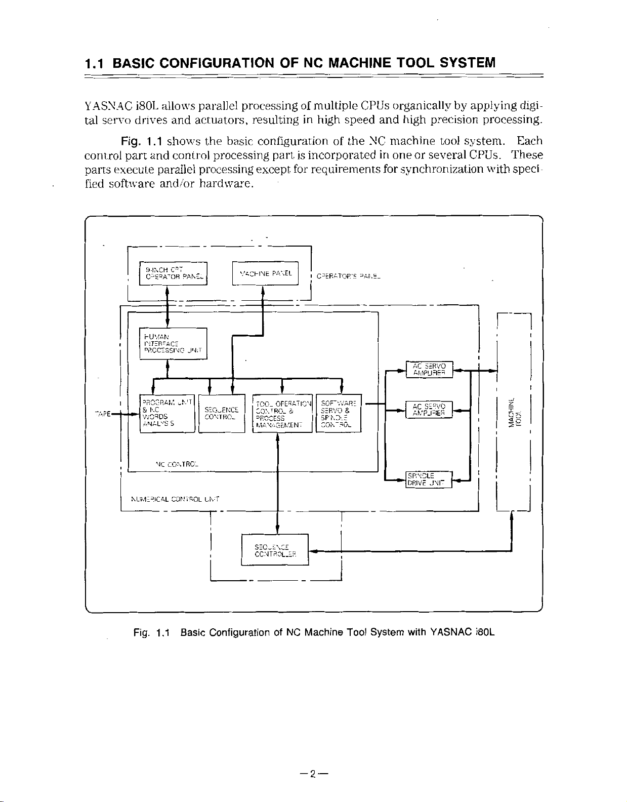
YASNAC
servo
tal
CONFIGURATION
and
parallel
actuators,
i80L
drives
allows
OF
processing
resulting
MACHINE
NC
multiple
of
high
in
CPUs
speed
TOOL
organically
high
and
SYSTEM
by
applying
precision
digi¬
processing.
control
parts
software
fied
-APE-
1.1
Fig.
part
execute
CÿSRAÿQR'
I
DRCCz
l
3RCG
S
SSSs
shows
and
parallel
and/or
T
RAM,
NC
control
processing
hardware.
PANEL
JN;T
\!G
I
oN'T
basic
the
processing
|
•!ONTRCC.E
configuration
part
except,
PANEL
CHINE
V-
SÿENT
is
for
the
of
incorporated
requirements
I
CURATOR'S
=AKE.
\
SSL
I
machine
NC
in
for
or
one
synchronization
r+rrnm
tool
several
system.
CPUs.
with
l
I
i
Each
These
sped
I
11
NC
NUMERICAL
Fig.
1.1
CONTRO-
CONTROL
Basic
L.NT
Configuration
of
NC
Machine
T
Tool
HISZH
System
with
YASNAC
J
I
i80L
-2
—
Page 15
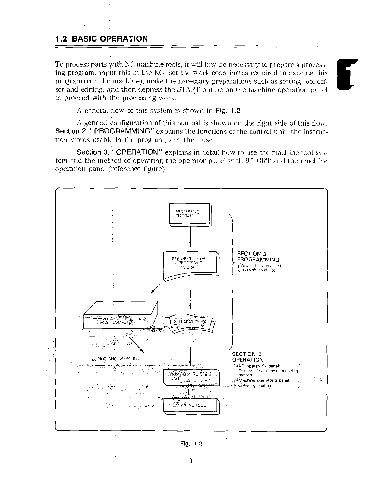
1.2
BASIC
OPERATION
process
To
program,
ing
program
set
and
proceed
to
A
A
Section
tion
words
Section
and
tem
operation
parts
input
the
(run
editing,
with
general
general
2,
“PROGRAMMING”
usable
3,
the
method
panel
NC
with
thisinthe
machine),
and
then
processing
the
flow*
of
configuration
the
in
‘“OPERATION”
of
(reference
machine
NC,
make
depress
system
this
of
explains
program,
operating
Figure).
tools,
set
the
the
work.
this
and
explains
the
will
it
work
the
necessary
START
is
shown
manual
the
functions
their
in
operator
oS'NG
first
be
coordinates
preparations
button
in
is
use.
detail
on
Fig.
shown
how
panel
necessary
required
such
machine
the
1
.2.
on
the
the
of
with
to
control
use
9"
to
right
the
CRT
prepare
to
execute
setting
as
operation
sideofthis
unit,
the
machine
and
the
process¬
a
tool
panel
flow.
instruc¬
tool
machine
this
off¬
r
sys¬
DURING
-NC
CP-:-A-|CN
/
;._T5
t'ASHNE
TOOL
SECTION
I
PROGRAMMING
fVe*-Sks
I
mathoos
SECTION
OPERATION
operator's
T»NC
1
sp
D
sv
'.Machine
Oper=ij
....
2
furu
cis
Of
3
's
ds:a
operator's
,e,roo
ansi
_$=
panel:
a-o
_.
'
oce-=!i-.g
panel:
V
Fig.
1.2
—3—
Page 16

1
.3
MULTI-PROGRAM
The
environment
called
controlled
is
in
which
a
CONTROL
NC
program.
processing
when
(only
programs
the
multi-program
executed
are
option
and
servo
is
provided)
axes
are
YASNAC
compound
thereby
details,
For
manufacturer.
turning
Individual
program
The
enabling
number
The
Section
noted.
iSOL
programs
refer
2
assumes
Processing
!
Analysis,
allows
machines.
also
can
processing
the
available
of
command
to
single
a
program
execution!
I
up
to
can
execute
perform
that
programs
or
program
Expmple
!
three
programs
processing
one
processinginconjunction
could
reference
of
not
and
varied
manuals
explanation
for
Programming
Processing
Analysis,
program
execution'
operate
to
performed
be
operations
program
issued
purposes
same
the
at
independently.
other
with
single
in
a
depend
by
your
unless
Processing
|
i
Analysis,
time
programs,
program.
machines.
on
machine
otherwise
programÿ
execution
j
under
tool
Servo
NOTE
axis
The
multi-
l
1
X
program
d£J“
Z
1
control
1
function
Program
Program
as
an
—
(ft
option.
dSSr
2
X
provided
is
_4
<50r
3
X
Z
2
2
3
Program.
Z
-3
Page 17
SECTION
2
PROGRAMMING
section
This
tions
(*!)]
SECTION
CONTENTS
PROGRAMMING
2
CONTROL
2.1
Ccnt'ol
2.1.1
Controllable
Input
21.2
2.
1.2.1
2.
1.2.2
2.1.3
V.ax.mum
2.2
PROGRAMMING
Process
2.2.1
Programming
2.2.2
1
2.2.2.
2.2.
2.
2
2.2.3
2
2.2
2.4
5
2.
2.2.
3
Buffer
2.2
Tape
2.2.4
2.2.4.
1
2.2.4.2
2.2
NC
5
.2.5.1
2
2.2.5.2
2.
3
5.
2.
4
2.2.
5.
2.
2.
5
5.
2.3
PREPARATORY
2.4
INTERPOLATION
T
Position
2.4
2.4.11
2.4.1
2
2
2.4
Linear
Chamfering
2.4.3
Rad
2.4.3.''
4.3.2
2
2.4.4
Circular
{G02,
4.5
Polar
2
AXES
Axis
Increment
input
Least
east
input
output
Least
Sneet
Lace
part
start/tape
Tape
Progarm
P'ogarm
Comment
Register
Code
Tape
codes
El
A/ISO
Tape
Paper
taoe
NC
taoe
tape
NC
Spicing
Keeping
.....
(modal
GOO
(non-modai
G06
Interpolator!
Designaton
us
Charrrering
Rounai.ng
lnterpo.afon!
G03,
Coordinate
describes
of
2
Numbe'
and
Axes
...
and
nc'ement
increment
nc'ement
Move
Command
Format
and
label
enc
start/program
part
part
and
autc-se;eci
ounce
check
NC
tape
tape
..
NC
FUNCTION
G
code
G
‘(G01
Comer
command
designation
G23)
G22,
Interpolation
the
control
.
Simultaneously
of
Output
Increment
and
x
1C
Values
skip
end
Multi-active
(G-FUNCTION)
0;
of
graup)
cede
of
:
)
G‘2|*.
1
(G01
.
(G
11)
12)
(G
programming
axes.
.
Register
*
(G126,
gmup)
....
...
G127)*
and
Optional
1
functions
[(including
functions
are
marked
*
Page
2.4.6
5
7
7
8
8
8
9
10
1C
'0
12
12
13
14
22
.
24
25
25
25
27
27
27
27
28
28
29
33
33
,
33
34
•
•
l®ÿ-wr2ÿ'''Sffiÿ(jiÿaÿCporcinate
'v.
.;:..V.ÿ--39jÿl8y£NfERiNG
40
42
46
Cy
2.4.7
Too:
Available
and
2.5
FEED
t
Rapic
2.5.
2.5.2
Cutting
2.5.2
1
Feed
Feed
2
2.5
2
2.5.3
Switcning
Fees
Screw
2.5.4
Screw
Multipe
2
5
5
2.5
6
Variaoie
7
2.5
Automatic
'
2.5.7
Accel/dece:
2
Accel/decei
2.5.7
2.5.3
Ove'ride
1
Cutting
2.5.8.
2.5
8.2
Raod
2.5.9
Dvvel
1
Dwell
2.5.9.
Speed
2.5.10
2.6
REFERENCE
1
6
2
Automate
2
2.6
Reference
Return
2.6.3
Second
2.6.4
2.7
COORDINATE-SYSTEM
Setting
2>.1
AiitomaticiSetting
2.7.2
Setting
\
2.7.4
2.8.2
Select
Radius
2.8.3
Incn/Metnc
Decimal
2.8.4
Irterpoaton
indrica!
Diameter
in
Po:ar
Cylind'ica
FUNCTIONS
Traverse
=eec
per
rotation
per
minute
oerween
per
Rotation
ng
Cutt
Cutt
ng
Threac
Lead
Acceeration
feed
traverse
(G04)
oer
minute
Controi
POINT
Reference
Pont
Reference
Tom
ib-Fourth
Coordinate
Ccproinate
Wo'k
COORDINATE
andrincremental
of
on
D
Specification
Input
Pont
(G124.
Compensaton
Coordinate
Interpolat
Rate
(G99
(G98
Mode)
Feed
(G93/G99)
and
Continuous
(G32)
Cutting
Screw
Cutting
Screw
and
rapid
cutting
overrde
overrde
t'ave'se
feec
o'
ol
Commanc
RETURN
Point
Cneck
Return
PontReturn
Reference
System
‘or
Coordinate
Specificat
ameter
input
X-axis
of
Specification
or
mode)
oer
Return
:
System
System
VALUES
Commands
optional
with
Gi25>*
Functions
Interpo
at
M
and
nute
(G32)*
(G34)
Deceleration
ana
ma.nua!
(G28)
(G29)
3oint
Return
System
(G50T.
on
and
G21)
(G20.
func¬
...
on
....
.
(G30)*
G5D*
*
'eed
.
Page
...
..
106
]
51
E
54
56
56
56
57
59
62
63
68
71
74
74
75
76
76
77
78
78
79
80
80
85
86
69
90
90
93
94
96
103
103
105
108
—5—
Page 18
SECTION
2
PROGRAMMING
(Cont’d)
SECTION
CONTENTS
SPINDLE
2.9
1
2.9
2.9.2
2.9.3
2
9.3.1
9.3.
2.
2.9.4
2.10
2.10.'
2.10.2T6
2'1
2.11.1
2.11.1.1
.1.2
2.1'.
2.H.1
2.1
‘.14
2.12
2.12.1
2.12.2
3
2
12
2.12.4
5
2
12
2.13
13.'
2
1.1
2.-3
2.13.1.2
2.13.1.3
2.13.2
'3.2
2
2.13.2.2
2.13.2.3
2.13
2
2.13.2.5
2.13
2
2.13.2.7
2.13
2.8
FUNCTION
Sp.ncle
Command
Spinole
Maximum
Speed
Command
Peripheral
Peripheral
xeeping
centre’
Cancelling
2
Keeping
Rotary
TOOL
T
MISCELLANEOUS
M
3
TOOL
Ofset
Tool
Ncse
Multi-active
Corner
Interna
PROGRAM
Canned
Mult
1
4
6
control
Too
FUNCTION
Specfication
4-cigit
Spec
digit
Funct
on
M
codes
MO',
(MOO,
Infernal
General
Move
than
OFFSET
Memory
Position
R
Compensation
Rounding
M
Cyce
Cutting
Thread
Threac
Repetitive
pie
Overview
d;amete'
Outer
End
face
C'csed
Finshlng
End
face
Outer
diameter
Automatic
2
{Cont’d)
Rotation
(G50S)
Speec
Keecmg
speed
(G96)
peripneral
(G97)*
Spindle
(T
fication*
FUNCTION
related
M02,
processing
M
other
one
M
Offset
Register
Judgement
Code
(M96/M97)
SUPPORT
(G90.
A
(G90)
cycle
cyde
cuttng
cyde
cutt.ng
rough
rough
loop
cutting
(G70)
cyde
ng
cutt
cutting
thread
(S
5-DIGIT
Control
*
speed
Select.on
FUNCTION)
.
stopping
to
M30)
codes
M
coces
command
(G40,
(M92,
FUNCTIONS
G92.
(G92)
(G94)
Cycle
(G70
cutting
cutting
cycle
cycle
cycle
off
cycle
catling
SPECIFICATION)
(G93.
Function
*
FUNCTION)
(M
in
block
a
.
G41/G42)*
M93)*
...
G94)
to
G761*
(G7')
cycle
(G72)
...
(G73)
(G74)
(G75)
(G76)
cycle
G97)*
Page
109
..
..
.
.
...
109
11
112
112
'13
'16
'17
H7
117
1'8
r-8
18
1
119
120
120
121
121
123
128
'.72
173
174
174
175
178
185
188
188
i90
200
205
209
2'2
215
218
2.13.2.9
2
2.13.3.1
'
2.13.3.2
2.13.4
2.13.5
2.13.5.1
2.13.6
2.13.6.1
2.14
2.14.'
2.14'.1
2.141.2
2.14.2
2
2.
2.14.5
2.14.6
2.14.7
2.14.8
2.14.9
2.14.10
2.14.11
2
2.15.1
2.16
2.
2
2
2.17
2.17
2.17.3
2.17.4
2.17
2.17
2.'
Remarks
Complex
13.3
Taper
rounding
Circular
rounding
Toe:
Offset
Progarm
Subprogram
Dolling
Drilling
MACRO
Macro
Macro
Argument
Variables
Speo'ymg
3
“'4
'4.
4
Quoting
Undefined
Arithmetic
Control
Entering
RS-232C
Macro
Macro
MEASUREMENT
AUTO
15
Skip
Function
STORED
'6.1
Stored
16.2
Stored
17
MULTI-SELECTION
MULTI-SECTION
(FOR
1
Section
Passworc
2
Control
Loca.
Section
Synchronous
5
6
Remote
Pulse
7.7
Copy
G70toG78
on
Chamfering
complex
command
complex
command
Amount
Cali
Canned
canned
PROGRAM
Progarm
nesting
desgnaticn
......
...
Variables
Variables
Variables
Commands
Commands
Macro
Data
Program
Program
STROKE
Stroke
Stroke
(G111,
chamfering,
{G1
11)*
chamfering,
(G112)*
Setting
(G10)*
Function
M99)
(M98.
Cycle
*
cycle
*
G66,
(G65,
Call
cal:
.".
......
.....
....
......
.....
.
....
...
Programs
Output-2
(G31)*
Limit
Limit
Aia-m
Examples
FUNCTION
LIMIT
CHECK
A
.....
B
(BPRNT,
Numbers
.....
-
SUPPORT
OPTION
Select
Spindle
Feed
on
Command
Command
Selection
Reference
M,
T
Command
Synchronizat
Command
Axis
Program
Function*
G112)
*
G67)*
.
DPRNT)
:
FUNCTION
ONLY)
*
Function
Spindle
Select
*
Page
224
227
227
240
248
250
250
252
252
267
269
274
276
280
297
298
299
300
303
308
309
.
314
315
322
322
324
324
325
332
332
337
340
*
341
.
343
*
344
345
—
—
6
Page 19
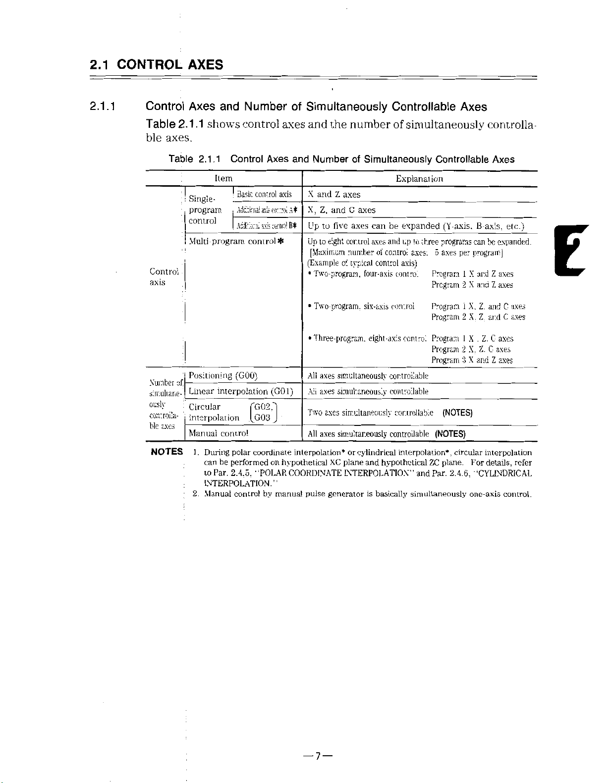
2.1
CONTROL
AXES
2.1.1
Control
Table
ble
Control
axis
Number
simultane-1
ously
controlla-
ble
2.1.1
axes.
Table
of;
axes
Axes
shows
2.1.1
:
Single-
;
program
.
control
Multi-program
Positioning
Linear
Circular
)
interpolation
Manual
and
Number
control
Control
Item
•
Basic
Adctienai
;
Actiora!
!
control*
(GOO)
interpolation
T
[C03
control
Axes
control
arts
cortroi
axis
ctcird
(G01)
G02T
of
Simultaneously
axes
and
and
Number
axis
At
Bt
X
X,
Up
Up
and
Z,
to
to
[Maximum
(Example
Two-program,
•
Two-program,
•
Three-program,
•
All
axes
AS
axes
axes
Two
All
axes
the
number
Simultaneously
of
Z
axes
C
and
axes
axes
five
eight
control
number
typical
o:
four-axis
six-axis
eight-axis
simultaneously
simultaneously
simultaneously
simultaneously
Controllable
simultaneously
of
Explanai
be
can
expanded
axes
up
and
of
control
control
axis)
control
control
controllable
controllable
controllable
controllable
control
to
three
axes:
ion
Program
Program
Program
Program
Program
Program
Program
Axes
Controllable
can
per
program]
1
X
X
2
1
X.
X.
2
1
X
2
X.
3
X
B-axis,
ar.d
ana
Z.
Z
.
Z.
and
(Y-axis.
programs
5
axes
(NOTES)
(NOTES)
controlla
Axes
etc.)
expanded.
be
Z
axes
axes
Z
and
C
C
ar.d
C-
axes
Z.
axes
C
Z
axes
E
axes
axes
NOTES
1
.
2.
.
polar
During
can
performed
be
to
Par.
2.4.5,
INTERPOLATION.”
Manual
coordinate
’TOLAR
controlbymanual
interpolation*
on
hypothetical
COORDINATE
pulse
cylindrical
or
plane
XC
generator
and
INTERPOLATION”
basically
is
interpolation*
hypothetical
simultaneously
and
ZC
Par.
,
circular
plane.
2.4.6.
interpolation
For
details,
refer
‘CYLINDRICAL
one-axis
control.
—
—
7
Page 20

2.1
CONTROL
AXES
(Cont'd)
2.1.2
2.
1.2.1
Input
Least
The
(1
)
are
Least
setting
(pm
(2)
Tool
or
(3)
In
in
(a)
(b)
(c)
Increment
input
increment
minimum
shown
input
parameter
Table
1000
Metric
Inch
Input
Input
DO-
2.1.3
'l
offset
0.001
mm
0.01
units
of
Write
Programming
Program
and
input
in
Table
increment,
Input
)
Lr.ear
Axis
:X.
ms:-.
0.0
1
0.001
value
deg*)
increment
0.01
operation
editing
Output
and
(prr.lOOG
-Vein;
lr.cn
pm
Increment
)
?t-:
V.
Z.
in
must
and
mm.
for
Increment
least
that
units
2.1.2.
2.1.2
Table
D0--O")
!r.pu:
Input
times
1000
C
Axis*
0.01
0.01
always
offset
is
system,
in
MDI
operation
operation
input
can
lira-
Ax'S
001
0
0.0001
ten
Do
at.
xK)
deg
deg
be
possible
mode
in
increment
instructed
be
Input
Least
V.
(X.
Z.
in
be
can
“1.”
NOTE
written
in
following
the
in
MEMORY
EDIT
Increment
C-
0.001
0.001
as
set
Metric
selected
G20/G21
in
0.001
these
mode
x
10
by
punched
Axis-
deg
deg
shown
input
by
command.
mm
units.
operation
mode
Table
in
and
setting
(or
tape
inch
pm0007
0.0001
must
2.1
input
be
or
MDI
.3
can
Ds
inch,
made
by
be
or
2.
1.2.2
1.
2.
3.
Least
Least
Metric
Out
Inch
NOTE
NC
If
mm
0.01
the
If
memory,
in
structed
When
punched
output
output
Table
X-Axis
Output
put
The
ieast
B-axis
manufacturer's
programs
increment,
increment
the
dimensions.
the
stored
out
increment
increment
2.1.4
value)
0.0005
mm
in
0.00005
output
depends
set
system
machine
program
stored”
“as
Least
increment
the
on
manual.
by
0.001
machine
the
is
is
the
Output
Z
0.001
0.0001
of
machine.
NOTES
mm
switched
move
will
punched
is
regardless
minimum
Increment
Axis
in
axes
extra
Refer
will
are
move
when
by
such
to
into
fed
ten
the
either
on
out
switching
of
unit
C
Axis*
deg
O.OOi
as
Y-axis
machine
the
the
of
tool
in
intended
of
NC
the
the
increment
motion.
stored
or
times
contents
timesorone-tenth
ten
the
tape,
of
and
equipment
dimensions.
are
tape
stored
figures
set
stored
of
the
system.
by
in¬
are
—
—
8
Page 21

2.1.3
Maximum
Move
Command
Values
Maximum
(1)
Table
W.
Metric
Output
Inch
Output
NOTE
The
cumulative
V,
and
,
;
the
If
In
1.
command
.
2
In
maximum
:
move
2.1.5
apply
H,
Table
Metric
|
Input.
Inch
j
Metric
|
Input.
Inch
i
maximum
incremental
absolute
value
Metric
input
Inch
command
only
not
alsotodistance
but.
2.1.5
Input
Input
value.
command
Maximum
Linear
values
are
programming,
programming,
value.
must
2.1.6
Table
Linear
input.
±
±39370.0787
±999999.999
±99999.9999
±999999.999
±99999.9999
values
move
to
Move
Axis
999999.999
exceeded,
move
not
Axis
Z,
(X.
correct
input
values
quantity
exceed
Maximum
Z.
:‘X.
are
shown
command
command
Command
V.
etc.)
mm
in
mm
in
operation
not
must
each,
axis
of
the
Cumulative
V,
etc.)
|
mm
in
below.
addresses
addresses
Values
C-Axis*
±999999.999
±999999.999
±999999.999
±999999.999
is
not
the
exceed
not
must
values
shown
Values
C-Axis*
±999999.999
±999999.999
I,
K.
deg
deg
deg
deg
guaranteed.
maximum
exceed
the
in
deg
deg
The
values
X.Z.Y.
R,
J,
A.
Table
C,
U.
and
B.
2.1.6.
in
E
NOTE
Listed
input
values
do
not
depend
bn
metric/inch
output
system.
—
9
—
Page 22
PROGRAMMING
2.2
2.2.1
2.2.2
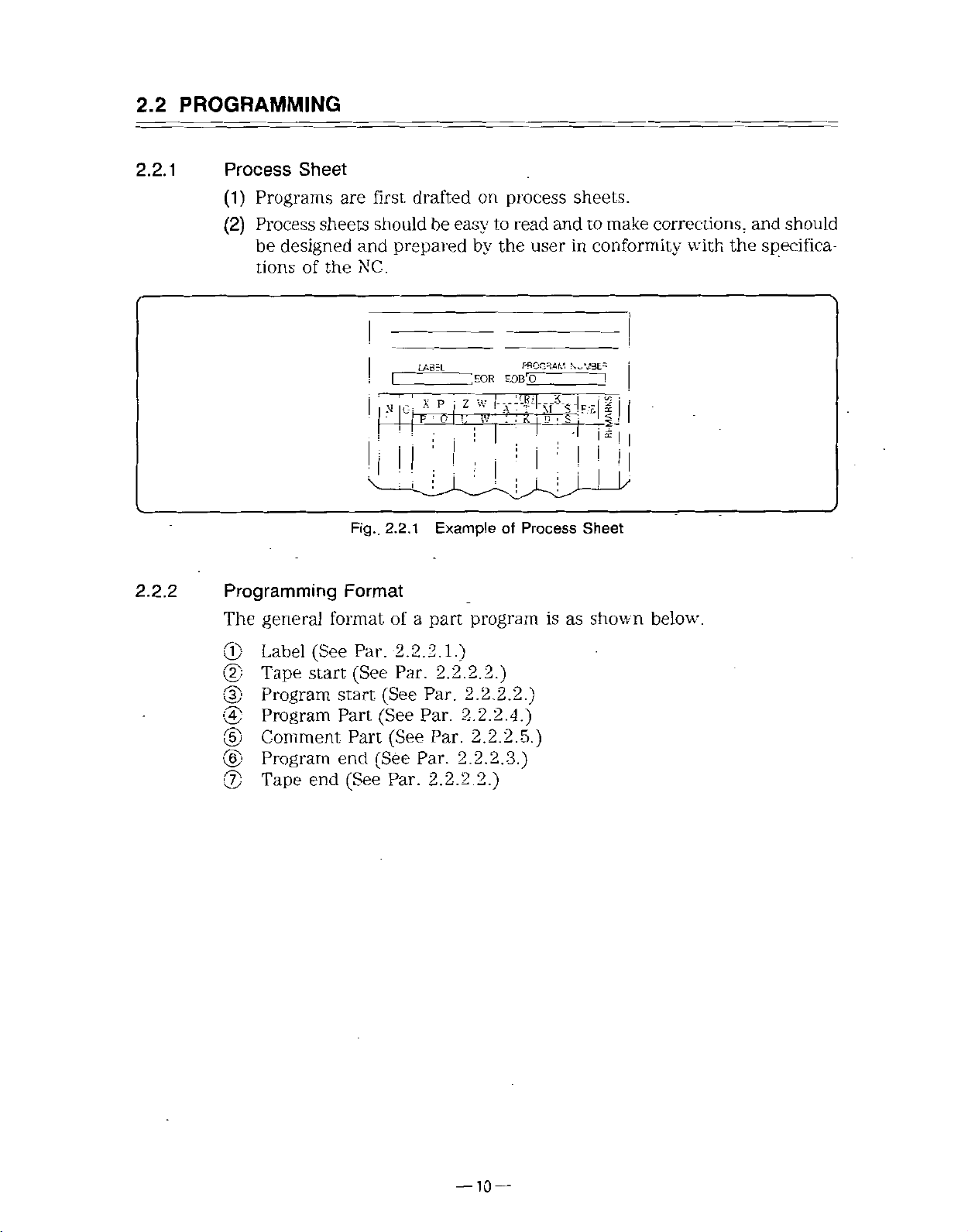
Process
(1)
(2)
Programming
The
Sheet
Programs
Process
be
tions
general
sheets
designed
of
are
and
NC.
the
Fig..
Format
format
first
should
prepared
i
N
i
!i
2.2.1
of
drafted
be
LA5=L
X
(C-j
;
i
a
part
on
easy
by
;EOR
w
P
z
±
i
'
Example
program
process
read
to
the
user
PPOGRAM
EOBÿCT
IKlD'3i
I
of
Process
is
sheets.
and
in
as
make
to
conformity
!
"ill
I
I
Sheet
shown
corrections,
with
below.
and
specifica¬
the
should
©
(2)
<D
0
(5)
(§)
>0
Label
Tape
Program
Program
Comment
Program
Tape
(See
start.
end
Par.
(See
start
Part
Part
end
(See
2.2.2.
Par.
(See
(See
(See
(See
Par.
2.
Par.
Par.
Par.
Par.
2.
1.)
2.
2.
2.
2.
2.
2.
2.
2.
2.
2.
2.)
2.)
2.
2.
2.
2.2.)
2.
4.)
2.
3.)
5.)
—
10
—
Page 23

:
o
NOTE
$
JStiS
Laoel
®
pan
(2;
As
Fig.
Taps
Tape
I
1
/
/
star
CT
the
2.2.2
E
P.
Start
E
R
/
(3)
i“Ffi"
ftog'*n
program
i
I
t
Program
cart,'
Tape
C
R
1
:
p-og!3TI
®
code
c
R
!
!
start
C-'
ends,
with
$
5‘D't
$
Icatec
“rew'nd
M02
P'ogtaT
Prcg'3'Ti
"ECB"
stop
and
Single
pan
cart
zoce
code
M
M99
'H4-
--ÿÿ'Cc'rrrsr:
1
i
'
end
Q:
")
I
3
0
erb
=-cg'3Ti
car.
Program
orrrrert
c--'
fc'ocsc
c
R
1
be
suosniuicd
(EIA
i
38rt-»»J
coos'
!
E
I
R
1
\'
\
(J
3D6
code)
l>
part
i
i
eno
for
E
M-30.
—
\
i
(J)
Program
Fig.
oar
Prog
(J)
2.2.3
'an
Tape
par
1
I
rj;
f
T
T
3
V.
1
'ogsrm,
with
Multi-Program
11
—
0
end
—
1
c
R
-
-,.Z
oar.
P'cgram
3>
'I
a
|jJ
(EIA
end
Code)
-;2D
j
R_
R
|
»ÿ
j««i
fc-j
i
,
\
‘
(D
305
nG
8
Page 24
2.2
PROGRAMMING
(Cont’d)
2.2.2.
2.
2.
2.2
1
Label
To
ten
tion
part
facilitate
the
in
of
data
addresses
modified
The
;'LSK”
j
0
0
j
(3)
punched
Tape
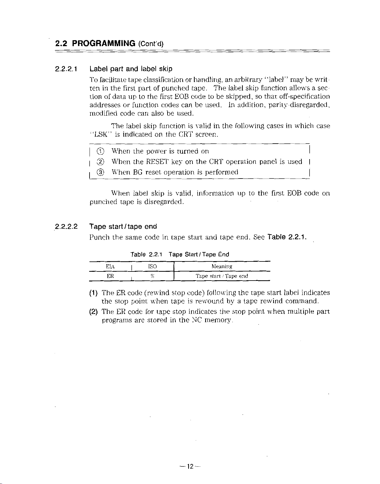
Punch
is
When
When
When
When
start
the
label
and
tape
first
part
up
to
or
function
code
can
label
indicated
the
the
BG
label
is
tape
/tape
same
skip
classification
punched
of
the
first
EOB
codes
alsobeused.
skip
function
CRT
the
on
skip
is
turned
key
operation
valid,
is
power
RESET
reset
disregarded.
end
code
in
tape
handling,
or
tape.
code
be
can
is
valid
screen.
the
on
information
start
The
be
to
used.
in
on
CRT
performed
is
and
arbitrary
an
label
skipped,
addition,
In
following
the
operation
up
end.
tape
skip
to
‘‘label”
function
that
so
may
allows
off-specification
parity-disregarded,
is
first
Table
in
used
EOB
2.2.1.
cases
panel
the
See
be
which
|
code
a
I
writ¬
sec¬
case
on
(1)
The
the
(2)
The
programs
ElA
ER
ER
stop
ER
Table
i
code
point
code
are
2.2.1
ISO
%
(rewind
w’hen
for
tape
stored
Tape
stop
tape
stop
in
Start
code)
is
indicates
NC
the
/Tape
Tape
End
Meaning
start
following
rewound
memory.
/
the
Tape
by
stop
end
the
a
tape
tape
point
start
rewind
when
indicates
label
command.
multiple
part
—12—
Page 25
2.
2.2.3
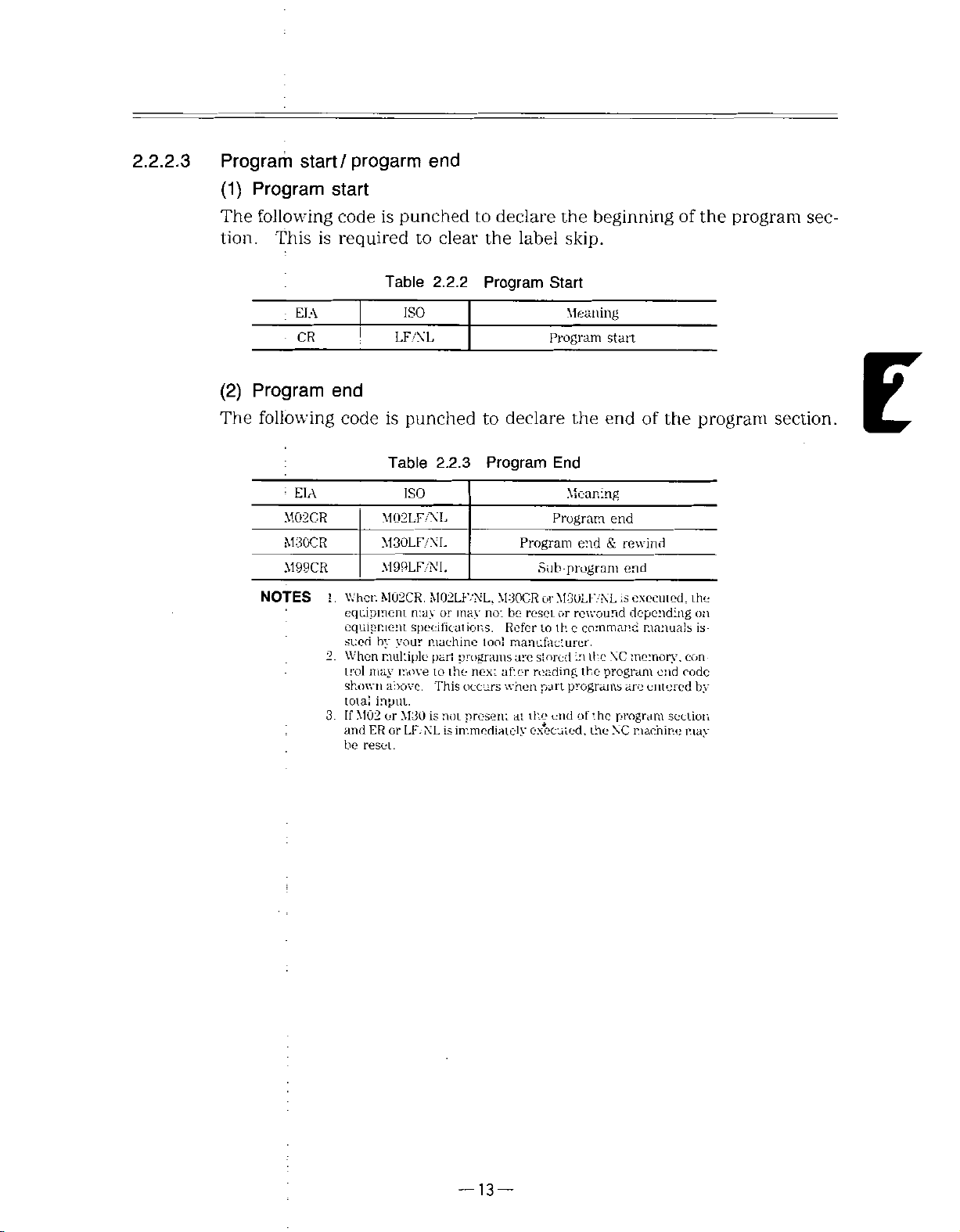
Program
start/
progarm
end
(1)
The
tion.
(2)
The
Program
following
This
EIA
CR
Program
following
=
EIA
M02CR
M30CR
M99CR
NOTES
start
code
required
is
end
code
I
.
When
equipment
equipment
sued
2.
When
trol
shown
total
If
3
and
be
is
Table
is
Table
M02LF/NL
M30LF/NL
M99LFAM.
M02CR.
by
multiple
may
above.
input.
M02
or
ER
or
reset.
punched
clear
to
2.2.2
ISO
LF/N'L
punched
2.2.3
ISO
M02LK/NL,
may
or
specifications.
your
machine
part
to
move
This
is
M30
not
is
LF.-NL
to
declare
the
Program
to
Program
may
not
tool
programs
the
next
occurs
present
immediately
beginning
the
skip.
label
Start
Meaning
Program
declare
the
start
end
End
Meaning
Program
Program
M30C-RorM3ULF/NL
be
reset
Refer
manufacturer.
are
after
when
the
at
program
Sub
or
to
th
stored
reading
programs
part
end
executed,
end&rewind
rewound
command
c
in
the
program
the
of
the
the
of
end
end
executed,
is
depending
manuals
memory,
XC
are
program
machine
NC
of
the
end
entered
section
the
program
the
on
is¬
con
code
by
may
program
section.
sec¬
E
:
—13—
Page 26

2.2
PROGRAMMING
(Cont’d)
2.2.
2.
4
Program
A
punched
called
is
The
prised
of
Each
part
the
several
R
NOTE
section
program
program
words.
block
vvCFD
-m
-
EOB
(program
from
section.
section
separated
is
WORD
5_0C<
Fig.
the
consists
WOFC
-
start.;
2.2.3
program
of
by
the
BLOCK
-
is
represented
Block
Definition
start
several
EOB
PÿOGPAV
by
all
code
=>ART
‘V*
way
the
blocks,
(;).
in
this
and
manual.
to
the
each
program
block
is
end
com¬
(1)
Program
(a)
(b)
adding
Bv
is
it
A
program
lowing
equipment.
increased
be
number
a
possible
No.
address
program
discriminate
to
can
0.
However,
299
to
immediately
No.
specified
be
Up
to
the
999
or
your
by
program
99
maximum
by
adding
behind
program
to
five
up
Nos.
number
options.
the
from
digits
can
of
program
other
numbers
of
be
entered
program
start
code,
programs.
fol
the
for
Nos.
can
—
14
—
Page 27

(2)
Sequence
number
NOTE
(c)
1.
2.
3.
(a):
Integers
dress
:
Sequence
(b)
any
;
Therefore,
;
;
numbers.
Generally,
;
When
program
When
the
to
When
retrieved
Blocks
the
character
influence
sequential
searching
or
6
5th
two
and
without
address
consisting
numbers
on
they
numbers
numbers
digits
more
from
the
or
more
read,
sequence
data
contained
up
of
N
sequence
as
are
reference
the
meaning
may
be
are
sequence
for
beforehand.
are
written
trailing
blocks
and
end
have
no
more
numbers
in
5
digits
to
numbers.
numbers
or
sequential,
convenient
numbers,
NOTES
sequence
as
a
are
effective.
the
same
searching
can
also
blocks.
the
may
be
sequence
non
sequence
as
be
sequence
performed.
is
be
searched
written
blocks,
for
of
machining
-sequential,
numbers.
sure
number,
search
to
only
number,
for
with
following
and
do
processes.
duplicated
or
or
digits
the
only
one
respect
an
have
not
specify
up
is
to
ad-
E
Word
(3)
A
block
andanumeral
:
UU
[Address
:
i
is
collection
a
Word
of
several
02
Numeral)
of
words.
A
word
digits
that
[Address
Word
consists
follow
Numeral)
of
the
address.
(Includes
decimal
an
address
a
sign
point)
(alphabet)
and
—
15
—
Page 28
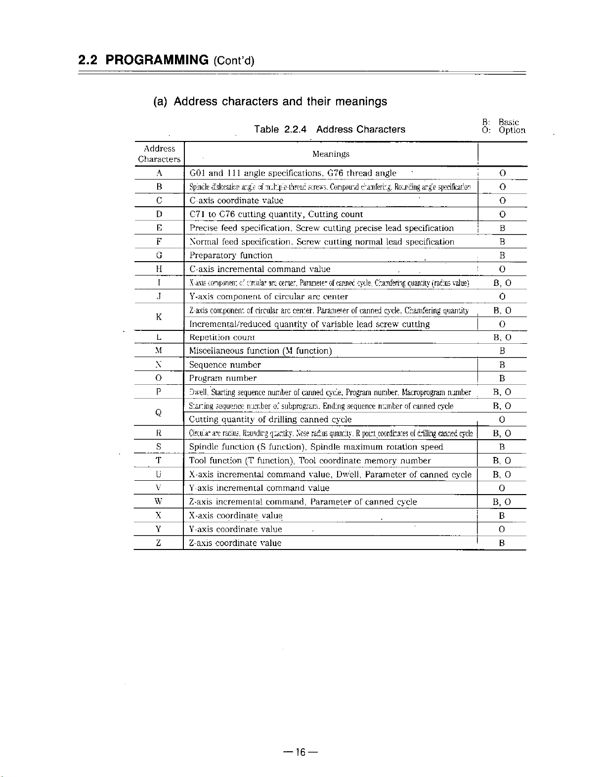
2.2
PROGRAMMING
(Cont’d)
(a)
Address
Characters
A
B
C
D
E
F
G
H
I
K
L
M
X
O
P
Q
R
S
T
U
V
W
X
Y
Z
Address
G01
Spindle
C-axis
characters
and
1
dislocation,
coordinate
C-71toC-76
Precise
Xormal
Preparatory
C-axis
X-axis
Y-axis
Z
Incremental/reduced
Repetition
axis
component
component
feed
feed
incremental
component
Miscellaneous
Sequence
Program
Dwell,
Staring
Cutting
Circular
Spindle
Tool
X-axis
Y-axis
Z-axis
X-axis
Y-axis
Z-axis
number
Starting
sequence
quantity
arc
radius.
function
function
incremental
incremental
incremental
coordinate
coordinate
coordinate
Table
1
1
angle
angle
of
cutting
specification,
specification.
function
c:
circular
circular
of
count
function
number
sequence
number
of
Rounding
(S
(T
function),
and
their
2.2.4
specifications.
multiple-threat
screws.
value
quantity.
command
arc
circular
of
quantity
Cutting
Screw
Screw
value
Parameterofcanned
center.
arc
arc
center.
function)
(M
numberofcanned
subprogram.
of
drilling
quantity.
function),
canned
Nose
Tool
command
command
value,
value
command,
value
value
value
meanings
Address
Meanings
cutting
cutting
center
Parameterofcanned
variable
of
cycle.
Ending
radius
Spindle
coordinate
Parameter
Characters
G76
thread
Conpourd
count
precise
normal
cycle.
lead
Program
sequence
cycle
quantity.
P.
maximum
Dwell,
of
chamfering.
poir.t
memory
Parameterofcanned
canned
angle
argle
Routing
specification
lead
specification
lead
Chamfering
screw
number,
.coordinates
quantity
cycle,
Chamfering
cutting
Macroprogram
numberofcanned
of
drilling
rotation
speed
number
cycle
specification
value)
(radius
quantity
number
cycle
cycle
canned
cycle
B:
Basic
Option
0:
O
0
O
0
B
B
B
:
O
O
B,
0
0
B.
O
O
B,
B
B
B
0
B,
0
B,
0
B,
0
B
B,
0
0
B,
O
O
B,
B
O
B
—
16
—
Page 29
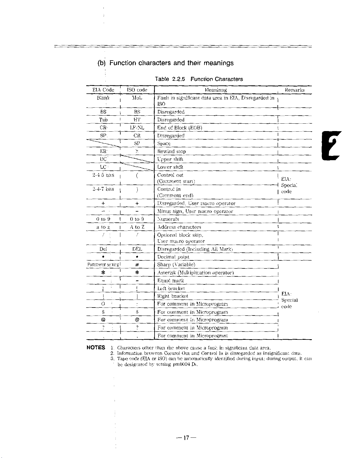
i
(b)
Function
Code
EIA
Blank
BS BS
Tab
CR
SP:
ER'
uc;
LC
5
2-4
oits
2-4-7
bits
+
0
9
to
z
a
to
i
Dei
Parameter
setting
*
O
S
@
9
characters
Table
T
ISO
code
MuL
Fault,
and
2.2.5
significant
in
ISO
9
Z
Disregarded
Disregarded
Block
End
of
Disregarded
Space
Rewind
Upper
Lower
Control
stop
shift
shift
out
(Comment
Control
in
(Comment
Disregarded.
sign.
Minus
Numerals
Address
Optional
User
Disregarded
Decimal
Sharp
Asterisk
Equal
Left
Right
For
For
For
For
For
characters
block
macro
point
(Variable)
(Multiplication
mark
bracket
bracket
comment
comment
comment
comment
comment
start)
end)
User
operator
(Including
i
i
HT
1
LF
XL
CR
SP
%
+
1
>:
1
1
+
I
0
to
A
to
/
DEL
I
I
#
I
*
!
t
S
@
9
meanings
their
Function
Meaninng
data
(EOB)
macro
User
macro
skin,
Microprogram
in
in
Microprogram
in
Microprogram
in
Microprogram
Microprogram
in
Characters
in
area
All
operator
EIA.
operator
operator
Mark)
Disregarded
j
in
|
i
1
I
1
EIA:
4
Special
code
|
l
EIA:
Special
code
1
Remarks
E
NOTES
Characters
1.
2.
Information
Tape
3.
be
other
(EIA
code
designated
than
between
ISO')
or
by
setting
the
above
Control
can
pm0004
cause
Out
and
automatically
be
Dc.
—
—
17
a
fauk
Control
it:
significant
disregarded
is
In
identified
during
data
input:
area.
insignificant
as
during
output,
data.
can
it
Page 30

PROGRAMMING
2.2
(Cont’d)
(c)
1
I
X
Numeral
(
i
)
specification
A
variable
Standard)
)
Table
(
ii
lowing
programmable
ming.
whetheradecimal
2.2.6
A
range
block
B631-3
the
format
is
shows
address
used
numeral
number
decimal
Processing
-j
6
point
is
point
Explanationofinput
3
L
Down
decimal
Six
integer
Sign
(input
conforming
for
YASN'AC
specification
characters
digits.
of
should
performed
specified.
is
third
to
place
digits
of
format)
to
in
Omitted
be
differently,
format
JIS
i80L.
ranges.
Table
For
Differs
and
format.
[See
(Japanese
2.2.6
actual
in
depending
details,
see
[
in
inch
and
(e)
Industrial
Numerals
indicate
program¬
Par.
2.8.3.
metric
input
(f).]
fol¬
the
on
I
I
!
I
NOTE
(iii)
The
address
Tne
minus
leading
codes
sign
zeros
(-)
Address
and
including
be-
cannot
the
sequence
omitied.
character:
plus
sign
X
can
(+)
numbers.
be
omitted
for
all
—
18
—
Page 31

(iv)
(v)
(vi)
In
the
manual.
represented
is
(EIA
code)
semicolon
Metric
05
F33
Inch
05
F24
input
No
S5
input
N5
S5
by
or
LF/NL
(;).
format
G3
T(2
format
G3
T(2+2)
EOB
a
2)
+
a
a
of
(end
block)
semicolon
(ISO
code)
63
+
M3;
54
+
M3;
(;).
should
code
actual
In
in
program
a
programming,
be
used
instead
example
CR
of
the
NOTES
No.
1
2
3
4
5
6
7
8
9
10
11
12
13
14
15
“a”
1.
Q,
P.
meanings
:
Program
Sequence
G
function
Coordinate
a:
X.Z.LK.U
'
Q.Y.J
b:
C.H
per
Feed
Feed
and
rotation
S-function
T-function
function
M
Dwell
Program
Sequence
repetitions
No.
of
angle
Line
Multiple
bread
1
-
represents
and
R
suchascanned
Address
No.
No.
Address
W,R.
minute
screw
designation
No:
designation
No.
designation
ancle
screw
axis
L
are
lead
cesigratu
command
omitted
Table
per
r.
in
cycles.
2.2.6
Metric
Metric
a
+
or
FSO
F33
E34
addresses
the
above
Output
input
05
No
G3
63
b
+
F63
S5
T
(2+2)
T
(3
+
M3
.
U
(P)
P5
Q(P)5
L9
A
(B)
B3
format
Input
Ir.ch
-
a
63
F5I
F24
E2C
3)
63
33
such
Formats
Input
o4
or
rou
X,
as
because
Metric
a
;
F60
Z.
+
nr
F33
E34
Y.
they
Inch
input
63
b
F63
T
T
U
Q
A
C,
U,
tire
Input
!
05
N5
G3
j
I
+
T
S5
(2
+
(3+3)
M3
(P)
P5
(
P)
L9
(B;
B3
W,
Ir.ch
a
63
F51
2)
63
5
33
used
+
o:
F24
E26
V.
input
54
F54
H:
for
and
I.
various
B:
O:
4
K.
Basic
Option
B
B
B
O
B.
0
B
B
B
B
B
0
B
B
B
B,
0
B
O
0
E
NOTE
-‘Input
;
format
pm2004
pm2004
for
DO-O
D0=1
feeding
-F60
=F63
per
minute
mm/min,
mm/min,
—
19
is
F52
F54
—
selected
in/mm
in/mm
by
pm2004
DO.
Page 32

2.2
PROGRAMMING
(4)
Block
(a)
One
code
(Cont’d)
block
is
is
represented
terminated
by
with
“CR!!
the
endofblock
in
EIA
or
i:LF/NL”
(EOB)
code.
in
ISO.
The
EOB
1
(a)
Character
1
NOTE
NOTE
X
The
(b)
(c)
The
N
number
0
058
Use
and
Up
maximum
i
2
EOB
code
only
2.2.5.
to
128
GOO
matching
G03X-Z-
in
programming
the
address
characters
number
X
40000
cÿarscts-s
20
TV
for
•128
characters
of
characters
check
examples
codes
can
Z
200000
=
even
H
iess
o-
-..nte-;
(if
per
and
be
does
an
blcrx-
in
this
manualisindicated
function
written
not
include
odd
number,
M
in
Del
•••
codes
one
and
fault,
...
F
by
shown
block.
otherinvalid
may
result)
for
in
Tables
characters.
]
simplicity.
2.2.4
]
(b)
Number
of
effective
characters
allowed
Fig.
in
2.2.5
one
block
Block
—20—
Page 33

(5)
:
Optional
Those
tween
skip
of
switch
a
block.
blocks
/n
block
and
for
in
the
that
skip
which
end
(12
(/1)
"/n”
of
that
number
to
(n
block,
“n’!
/9)*
=
l
is
to
on;
is
9)
when
/n
included
the
be
can
are
external
specified
disregarded
optional
the
in
middle
be¬
block
NOTE
i
i
With
-/r\
(EXAMPLE)
;
1
.
The
optional
from
the
subsequent
readingorpunching
While
2.
“l”
block
tape
switching
can
I
When
ed,
as
i
into
be
omiucd.
/2
K1234
the
and
if
1234
N
skipping
the
buffer
on
GOO
switch
when
G01
NOTES
process
storage.
is
ineffective
programs,
out
X
for
the
X100;
is
100/3
is
/2
switch
i
executed
If
the
skip
to
the
Z200;
the
on.
for
/3
while
program
the
skip
1
entire
is
on,
a
part
has
blocks.
function
block
this
program
already
is
ineffective.
disregard¬
is
block
is
read
read,
been
is
read
E
i
—
21
—
Page 34
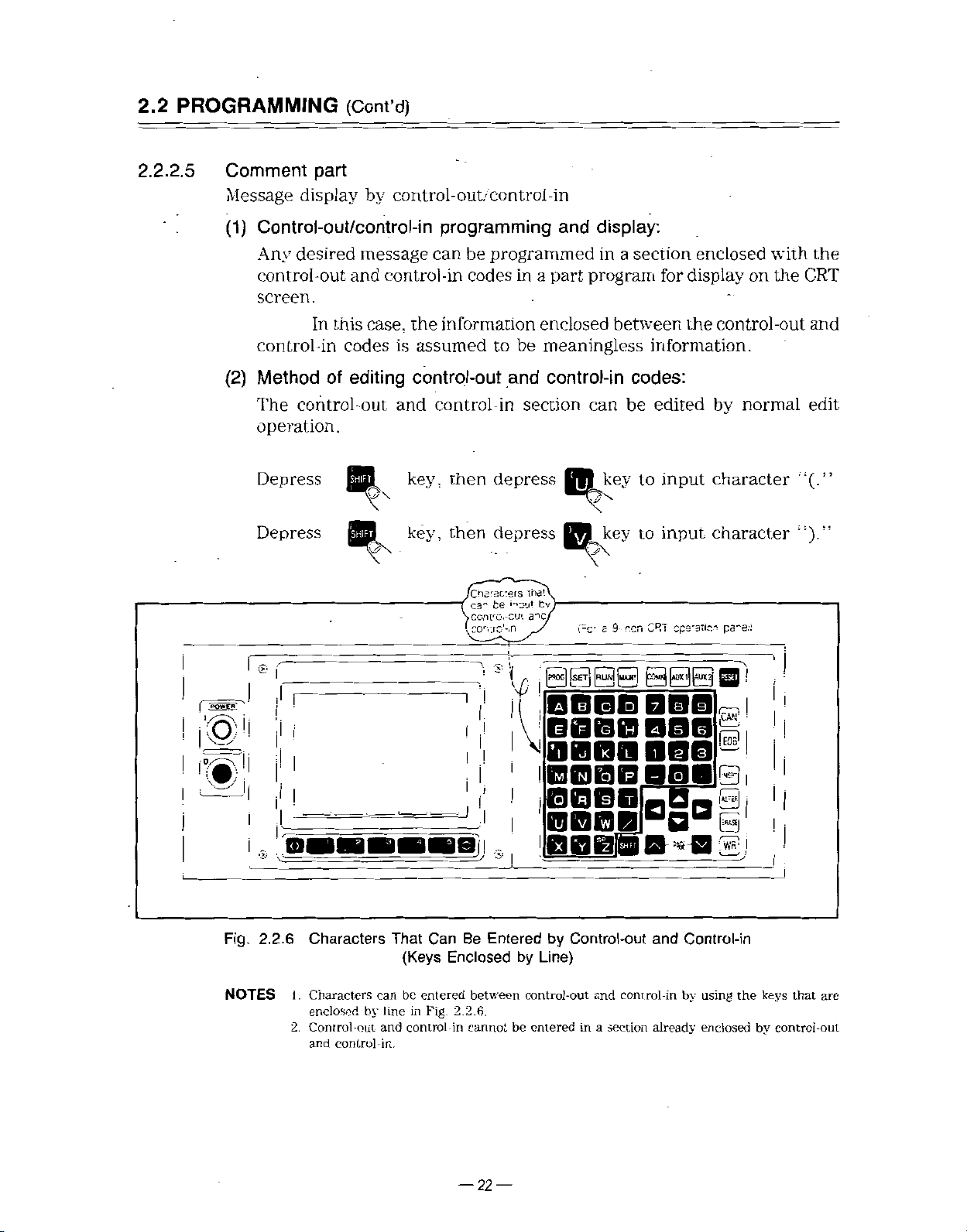
2.2
PROGRAMMING
(Cont’d)
2.2.2.
5
Comment
Message
(1)
Control-out/control-in
Any
control-out
part
display
desired
and
screen.
In
this
control-in
(2)
Method
The
operation.
Depress
Depress
control-out
codes
of
editing
by
control
message
control-in
case,
the
is
assumed
control-out
and
key,
key,
control
-out'
programming
can
programmed
be
codes
in
information
be
to
and
control-in
then
then
[Characters
C3"
iconro.-cin
eon.rc'-.n
section
depress
depress
••'IXJ!
be
-in
display:
and
in
program
part
a
enclosed
meaningless
control-in
can
Hÿkey
lna'\
fcv
a~>cj
V
i-c-
a
section
between
codes:
be
to
key
to
r-.cn
s
9-
enclosed
display
for
control
the
information.
cpe-ancÿ
by
character
character
pa-ei!
edited
input
input
CRT
with
the
on
-out
normal
the
CRT
and
edit
;i(-”
I
I
I©1!
I
iÿTi
Fig.
NOTES
®
r
I'I
|l
S
Vi
2.2.6
I
m
Characters
1
.
Characters
enclosed
2.
Control-out
and
control
by
can
line
and
-in.
That
(Keys
be
in
control-in
Can
Enclosed
entered
Fig.
Be
between
2.2.6.
cannot
®
!
\
\o
I
I
Entered
by
be
|RL»3
|SET|
|p°oc|
|MUT|
BOBU)
BQBfiS
Vi
BBBBOBB-I
IflPBB
|AU»I|[AUXÿ
BBS
BBS
BBB1R
BB0B|DaaB
-
and
already
B
Control-in
by
using
enclosedbycontrol-out
BB6M
by
Control-out
Line)
control-out
entered
in
and
a
section
B
control-in
&
r—
6
si
)
the
!
|
i
!
keys
that
are
—22—
Page 35

(Example
of
programming)
r
(TEST
GOO
X100.
XO
G01
(DRILL
(Example
PROGRAM
(TEST
X100.
GOO
;
!
G01
XO
(DRILL
:
PROGRAM)
Z100.
ZO
END)
message
of
RUN
PROGRAM)
Z100.;
F
ZO
END)
F10.
10.
;
;
;
;
display
;
;
l
by
control-out.
012345
;
or-in)
N00018
—
23
—
Page 36

2.2
PROGRAMMING
(Cont’d)
2.2.3
Buffer
Buffer
(1)
(a)
(b)
(c)
Multi-active
(2)
(a)
Register
register
During
offset
In
of
for
One
For
M92,
computing
nose
the
data)
the
bclock
the
up
Multi-active
and
normal
radius
read
are
next,
operation
can
Register*
portion
7
blocks
to
M
code
M93
M92
operation,
is
made
compensation
in
advance
is
contain
of
a
part
of
2.2.7
Table
Register
blocks
two
for
and
executed.
up
to
program
are
data
M93
Multi
Multi
of
following
the
blocks
two
,
compensation
characters
128
data
are
readinadvance
operation.
of
data
computing
including
sandwichedinbetween
readinadvance.
M92
and
Meaning
active
-active
Codes
register
register
off
on
(or
up
4
to
required
EOB.
M9-3
and
blocks
and
NOTE
(b)
Inter
that
longer
blocks
Advance
M93
in
block
the
automatic
than
of
reading
mode.
stoppage
the
data.
no:
is
can
be
operation
processing
for
every
made
eliminated
when
timeofadvance
advance
of
time
,
clocks
but
is
always
program
the
reading
reading
ready
issomade
7
of
blocks
the
of
made
up
to
be
to
next
7
is
7
blocks
—
24
—
Page 37

2.2.4
2.2.4.
Tape
1
Tape
(1)
Code
codes
With
this
control,
both
the
EIA
codes
and
ISO
codes
can
be
used.
2.2A.2
ElX
ISO
Table
(2)
Before
made
EIA/ISO
(1)
The
completed
(2)
The
ting
mined
data
(3)
For
DO.
When
When
code
code
2.2.8
starting
as
the
to
auto-select
equipment
NC
code
No.
are
punching
automatically
is
pm0004
by
the
read
the
contents
the
contents
EIA
ISO
shows
program
to
codetobe
code
tape.
DO.
EOB
code
by
the
tapes,
RS-244-A
840
the
EIA
any
must
discriminated
This
first
determined
the
code
setting
of
setting
of
and
ISO
machining
used.
be
switched
is
automatically
read
must
a
in
code.
be
number
number
punched
over
regardless
lable
selectedbythe
pm0004
pm0004
tape
operation,
prior
so
set
skip
state
DO
DO
formats.
a
to
of
the
that
and
setting
are
are
decision
operation
contents
the
codeisdeter¬
subsequent.
the
of
;il”
:i0’!
...
...
EIA
ISO
be
must
by
the
of
set¬
pm0004
code
code
E
i
—
25
—
Page 38

PROGRAMMING
2.2
!
c.
!
•
10
c_
c.
.
o
o.
c.
c
o
NOTES
|
»>
o
Q
o
.
o
o
O
I
O
I
c
c
!
I
c
o
OOP
;
o
O
0
c
o o
c.
0
c.
c
i
O
c.
o
CTC
c
!
o
o
c
o
o.o
c
I
C
O
0
0.0:0
O
O
I
C
o
o
•
O
o.
o
O
•0
O
O
I
o
c.
IOi
O
O
i
!.
2.
KIA
|
•'.
c.
o.
o
O
'
o
o
0
1
C
o
o
o
o
o
O
c.
•
O
C
o
o
0.0
OJO
See'
O
.Oh
o
G
.
For
system,
EIA
(Cont’d)
Cirfa*
Q
!
4
c
c
.
c-
o
'
_
£
S
-
o
'c
O
c
=
-
p
c-
°
O
O
o
=
=
O
°
c
=
o
C
o
z
=
o
°
c
=
J
C
o
o
°
0=10
0
0
G
o
O
~
i
I
C
=
1
o
O
O
;
O
•
P
c
=
=
2.
Note
c
i
O
c-
!
G
C
o.
C
c
=
O
i
-
characters
code
C
O,
O
I
I
c
’
c
O
I
I
c
G
c
O
:
o
O
c
O
o
C
;
c
o
I
C
I
c
c
o
I
1
C
I
the
for
character
of
'
I
!
:
I
2
Q
c
G
c
c.
c
o
c
o.
c
o
To
C
Cu
o
O
o.
c
Ole
o
o.
o
c
o
o
c
O
O
from
time
1
-
1
Tc
I
1
o
“
c
o.
c.
o
c.
c
o
o
o.
o.
o.
Cl
O
o
o
c
O
#
Table
:
i
to
being,
can
#
B!a:ik
Tal.
uc
ik-:
?.
2.2.8
a
r>
c
c.
e
f
JL
h
i
i
k
n
o
JL
r.
r
s
t
II
w
X
V
2
H
C
kK
LC
1.1
EIA
the
be
Tape
Characters
II
2
3
4
5
>!
s
9
BS
SP
-b
Mark
All
it
*
1
$
have
codes
provisional
designated
Code
A
n
c
F
o
'
H
I
J
k
L
M
S’
0
p
_Q
R
s
T
V
w
X
Y
z
NUL
HT
LF.N:.
CH
%
DEI,
not
codesonthe
by
the
8
o
O
c
c
O
o
o
o
o.
o.
QIC
o
o
OL?
0
c.
o
o
c
o.
O
ClO'O'O
o
c
Q
C
o
o
I
been
parameter
7
!
,
-
G
c
o
C
:
o
o
c.
o_
o
.
G.
c
c.
Q
o_
o.
o
o
c.
O
o.
o
c.
c.
o.
:
I
C
!
O
o
i
o
agreed
left
;
6
o.
•c
c.
c_
o
O
o
o
c.
O
O
c.
o_
o.
c
o.
:
o
/O
Vw/
c.
1
O
o
c_
o
:
o
c.
c.
upon.
are
pm4100.
5
o
o.
o
O
o
c.
c.
O
O
o.
0
c.
o
o.
o.
c.
c.
Q
O
O
A
W
o
o
O
o
c.
used.
ISO
i
I
!
•
I
.
I
Code
4
o
O
C
Q
Q
o
cu
O
O
o
O
0
c
o.
Q
o.
o
O
O
o
c
c
O
O
Q|-
Q
o
O
c
O
C
In
c
3
c
o
c
o
O
:
O
O
O
°
C
.
O
i
=
g
o
G
o
o
-
o
Q
o
QIC
C
-
o
c
c
=
•0
O
:
Q
c
I
c
c
c
o
‘
o
G
:
C
o
°
c
c
=
o
c
c
c
!
O
O
o
.
S
C
o
j
o
:
O
c
.
-
O
O
o
i
c
o
:
O
I
°
o
o
C
;
c
=
g
o
!
O
a
O
!
o
1
c
O
o
i
:
present
the
:
I
I
1
-
;
I
i
2
o
o
c
c
o
c
Q
o.
o
c
c
o.
C
c.
C
o.
o.
o.
c.
c.
c
o
o
C_L
o
o
c
1
o
c.
c.
:
o
o.
o.
o
O
o.
.
o
c
o
Q
!
O
0
G
Q
o.
c.
o.
O
:
c.
c.
o.
=
o
o
c
o.
o
o.
o
—
26
—
Page 39

2.2.5
2.2.5.
Tape
NC
1
Paper
(1)
tape
For
part
forming
used.
are!
program
to
JIS
C624-3
tapes,
eight-channel
(width:
25.4
±
paper
0.08
tapes
mm,
for
computers
thickness:
0.108
con¬
mm)
2.
2.
2.
2.
5.
5.
2
3
(2)
The
cause
to
NC
tape
Part
(1)
in
paper
A
(2)
part
holes
NOTE
‘
tape
NC
Punched
functions.
Machine
;
•
M
|
•
shouldbeblack
color
reading
punch
programs
tape
program
For
er
at
using
E
the
tape
leading
reader
S'
check
part
program
lock
function
errors,
written
with
tape
using
reels,
lock
a
it
should
tapes
and
process
on
tape
should
and
6'
reels*
be
gray.
or
should
puncher.
be
trailing
the
,
the
at
least
can
be
Tapes
not
sheets
provided
ends.
feed
hole
m.
1
checked
with
be
are
with
should
by
high
used.
punched
proper
a
least
be
at
NC
an
transparency
EIA
in
or
ISO
length
and
70
with
cm.
for
the
tend
codes
feed
of
a
tape
react
following
E
-
•
|
•
i
Dry
run
Single-block
operation
—
27
—
Page 40

2.2
PROGRAMMING
Splicing
2.
5.
4
join
To
2.
end
tape
splices
only
the
NC
(splice)
without
(approx.
are
feed
the
After
holes
feed
(Cont’d)
tape
part
overlapping
0.08
available
holes
splicing,
before
program
in
mm
the
in
punched,
are
the
use.
tapes,
without
and
thickness)
fully
should
tape
the
two
space.
a
should
perforated
but.
the
be
ends
A
applied
be
type
former
checked
should
proper
and
is
more
for
be
length
on
the
in
convenient.
correct
placed
side.
one
type
alignment
splicing
of
in
end
Tape
which
to
of
2.2.
5.
5
NOTE
Do
as
Keeping
Generally,
cles,
with
use
not
these
NC
properly
one
rigid
industrial
conditions
o
tape
cycle
adhesive,
conducive
are
o
CO
oo
oooo
ooo
oooo
ooo
o o
ooo
oooo
ooo
ooo
APR
7
NC
TAPE
Fig.
2.2.7
maintained
consisting
to
o
oo
o
o
o
oo
oo
o
ooo
o
o
oooooooo
o
OO
o
ooo
oo
ooo
OX.
Splicing
part
of
and
co
jamming
o
o
oo
oooo
o
o
o
o
o ooo
ooo
ooo
30-rn
program
one
not
troubles.
o
o
o
o
ooooo
o
o
o
Part
reading
the
make
NCB
C-'ANNE.
?:R-ORA’E3
Program
tapes
and
joint
SPL
SLICING
Tape
C
can
one
too
NG
thick
.
TAPE
-TAPE
rJLLv
SILVER
last
at
rewinding
&
least
300
pass.
cy¬
NOTES
stored
program
.
1
Part
Do
handle
not.
2.
tapes
part
should
program
—
tapes
28
be
—
a
in
wearing
clean
gloves
area,
contaminated
free
of
contaminants
with
oil
or
and
cutting
humidity.
fluid.
Page 41

2.3
PREPARATORY
FUNCTION
(G-FUNCTION)
G
All
An
of
(1)
codes
address
the
block.
Normal
The
codes
in
this
character
codes
G
belonging
Non-modalGcodes
Effective
Modal
in
NOTE
Special
(2)
parameter
Once
the
They
When
the
only
G
codes
these
same
can
different
appearing
last
G
codes
be
code
pm400
manual
and
G
are
classified
division
to
(marked
specified
for
(groups
are
instructed,
group
programmed
G
codes
G
code
1
can
D7
is
instructed.
the
in
is
be
=
are
explained
up
to
3
as
with
blocks.
01
to
twice
same
group
effective.
substituted
1.
with
standard
digits
following
it
non-modalGcodes
are
B
included
in
*)
31)
they
or
arc
effective
are
more
in
programmed,
for
standard
the
specify
and
the
basic
until
same
G
code.
operation
the
modalGcodes.
specificaions.
anotherGcode
block.
by
code
setting
E
(3)
Wheh
comes
not
parameter.)
special
effective
selected,
G
code
by
special
Setting
is
II
setting
G
pm400
selected
parameter
I
code
D7
an
as
pm400
becomes
0
makes
to
option,
effective
standard
D7
the
to
special
.1
.
by
setting
G
(If
code
G
code
option
the
the
effective.
II
be
is
same
-29
—
Page 42

PREPARATORY
2.3
FUNCTION
(G-FUNCTION)
(Cont’d)
(4)
(5)
G
(a)
Group
01
03
04
The
cution.
code
The
Table
preset
shown
following
2.3.1
G
Selection
to
Code
or
GOO
G90orG91
G9SorG99
of
external
pmSOOO
in
be
G01
DO
Table
G
codes
of
Applied
current
2.3.1
can
G
Code
T
I
I
can
select
State
pm4000
pm4000
pm4000
value
Bit
0
1
selected
be
the
Power
at
Parameter
DO
Dl
D2
display
code
G
ON
Bn
o
1
Bil
o
1
Bit
o
1
can
Meaning
preset
Not
Preset
by
parameter
state
Code
GOO
GO!
Code
G90
G91
Code
C-95
G99
be
at
selected
-
setting.
power
G50
at
on.
exe¬
(6)
(7)
At
Group
01
03
The
reset,
status
corresponding
(8)
Circular
G22/23.
and
Chamfering
(9)
A:
At
At
At
G
code
Timing
power
reset
power
reset
radius
belonging
Table
)
ON
j
,
1
ON
|
Immediately
j
is
,
G
code
of
setting
specification
rounding
and
to
2.3.2
Parame'.er
Parameter
pm4000
pm4000
stored.
_
groups
of
data
group
01
and
Setting
pm4000
G01
G01
pm4000
Dl-0
D1
preceding
1
05.
ofGCode
DO
1
-
D6=
90
91
code
G
07,
(pmOOOTDO,
can
instructed
be
commands
can
0-3
1
be
at
f
08
and
pm0008D0,
by
can
use
by
set
Reset
Parameter
Parameter
pm4000
pm4000
pm4000
pir.4000
depends
code
G
G01
parameter
pm4000
GOO
GOO
pm4000
Dl-0
D1
-
Dl-0
Dl-1
the
on
and
each
of
instead
setting.
DO-O
D6-0
90
1
91
90
91
respective
pm0008Dl).
of
G02/03
of
1
G
1/12.
—
30
—
Page 43

Standard
G
.
codeGcode
GOO GOO
G01
G02
G03
G0-1
G06 G06
G10 G10
:
,
Gil
:
G12
G17
-
G18
tr
G19
;
-
G20 G20
G21
G22
G23
=
-
G27
G28
G29
f
;
G30
G3I
G32
G34
G36
;
G3t
G3S
G39
G40
G41
G42
G50
G51 G51
i
G65
h
!
G66
G67 G67
:
:
G70
G71 G71
i
G73 G73
‘
G75
G76 G76
NOTES
;
Special
G
I
G01
G02
G03
G04
Gil
G12
G17
G18ÿ
G19
:
G21
G22 G22
G23
G27 G27
G2S
G29
!
I
G30 G30
G31
G33 G33
G34 G34
G36
GST
G38
G39
G40 G40
G41
G42
G92
G65
G66
.
G70
G72G72
G74G74
G7-5
The
codes
1.
The
codes
2.
Special
code
GOO
G01
G02
G03
GO-4
006
G10
Gil
G12
G17
G18
G19
G70
G71
G2.3
G2S
G29
G3I
G-36
G37
G33
G39
G41
G42
G92
G51
G65
G66
G67
G72
G73
G74
G75
G76
G77
G78
maked
marked
B:
reset.
0:
Basic
Option
Divisicr
B
i
B
B
B
B
:
B
0
B
B
0
O
0
B
B
B
B
B
B
I
B
B.
B
B.
O
O
O
O
O
O
O
0
B.
O
O
O
u
O
O
O
0
0
O
O
!
o
I
z
0
0
O
Table
Group
II
01
*
01
16
05
01
*
01
07
08
06
*
*
09
*
with
with
2.3.3
Positioning
interpolation.
Linear
Circular
Circular
Dwell
Positioning
Tool
Chamfering
Rounding
XY
ZX
YZ
Inch
Metric
Circular
Circular
Reference
Automatic
Return
Return
Skip
Screw
Multiple
Stored
Stored
Stored
Stored
Nose
Left
Right
CTBSUB
Return
Simple
Modal
Canceling
Compound
caimed
cjtfe
interpolation
interpolation
offset
plane
plane
plane
input
input
interpolation
interpolation
from
to
function
cutting.
thread
stroke
stroke
stroke
stroke
radius
nose
nose
sneii
to
call
call
Finishing
Outer
End
Closed
End
Outer
Automatic
are
automatically
are
j
G
Codes
feed
(rapid
in
fault
detect
quantity
designation
designation
designatioti
designation
point
return
2nd.
radius
radius
;J
current
of
of
of
setting
designation
return
to
reference
4th
3rd.
Continuous
screw
2nd
limit
2nd
limit
3rd
limit
limit
3rd
compensation
compensation
compensation
hoi;
carat
value
macroprogram
macroprogram
modal
call
cycle
diameter
rough
face
loop
cutting
face
diameter
screw
automatically
Function
)
Angle
specification
CW
(radiusRspecification)
CCW
off
radius
radius
check
reference
point
reference
screw
cutting
area
area
area
area
cancel
Did
mm.
display
macroprogram
of
rough
cuuin.g
cutting
off
cutting
cutting
selected
selected
(radius
mode
designation
designation
point
points
cutting.
off
on
off
on
trig
Six
origin
cutting
cycle
cycle
cveie
off
cycle
power
at
at
R
cycle
interpolation
line
specification)
C-W
CCW
ana
power
cycle
on
sari
or
on.
—
31
—
Page 44

2.3
PREPARATORY
Standard
G
code
GSO
GS1
G82
G83
G83
G84
GS41
GS5
G86
G861
G87
G88
G89
G90
G92
G94
G93
G36
G97
GS8
G99
G105
Gill
G
1
G122
GI23
G124
G125ÿ
G126
G127
G130
G131
G132
G133
GI34
136
G
G137
G198\
G
199
:
1
-4
12
1
|
1
I
FUNCTION
Special
G
code
G80
GS1
G82
G83
G831
G84
G841
G85
GS6
GS61
GST
G88
G89
G77
G78
G79
G93
G9S
G97
G94
G95
G90
G91
G105
Gill
G112
G122
123
G
G124
GI25
G12S
127
G
G130
G131
G132
133
G
G134
GI36
G137
G19S''""1
G199
I
i
H
Special
|
G
code
!
G831
GS41
GS6
G861
G89
G20
G21
G24
G93
GS6
G97
G94ÿ
G95ÿ-
G90ÿ
G91
G105
Gill
G112
GI22
i
G123
G124
G12o'
G126
GI27
G
G
G132
G133
G134
G136
G137
G198'"''
G199
G80
G81
G82
G83
G84
G85
GS7
GS8
1
30
131
11
(G-FUNCTION)
14
01
04
02
04
03
I
20
19
21
22
*
23
15
*
I
2.3.3
Dhlltig
Sxed
cycle
Cutting
cutting
Screw
Cutting
tap
Solid
Peripheral
Canceling
per
Feed
Feed
per
Absolute
Incremental
Rotation
compound
Taper
compound
Arc
register
Tool
register
Tool
Cylindrical
Cylindrical
Polar
coordidnate
coordinate
Polar
Control
Control
Rotation
Rotation
MT
command
Synchronized
Synchronized
Return
to
to
Return
Tabie
Group
G
Codes
Canceling
cycle
Drill
Spot
facing
Deep
deep
Fast
cycle
Tap
Reverse
Boring
Boring
Boring
boring
Back
Borir.g
Boring
cycie
A
cycle
cycle
B
mode
speed
of
peripheral
minute
revolution
command
command
spindle
tool
start
end
interpolation
interpolation
axis
selection
axis
selection
tool
S
tool
S
to
feeding
feeding
initial
radius
(Cont’d)
Function
drilling
of
cycle
drill
hole
hole
cycle
tap
cycle
cycle
•
cycle
cycle
cycle
cycle
keeping
(mm/min)
(mm/rev)
synchronization.
chamfering
chamfering
mode
off
mode
command
command
command
command
other
systems
spindle
spindle
of
point
of
point
(Com
cymle
drill
control
speed
and
mode
mode
on
mode
mode
drilling
drilling
d)
canned
cycle
keeping
Rotation
rounding
and
rounding
on
off
cancel
cancel
selection
selectin
canned
canned
cycle
control
ratio
command
command
cycle
cycle
setting
cancel
B:
0:
Basic
Option
Division
0
0
O
O
0
0
0
0
'
O
0
0
O
0
B
B
B
0
0
0
B
B
B
B
O
0
0
O
0
0
O
O
O
O
O
O
O
0
O
O
NOTES
The
1.
2.
The
codes
codes
marked
marked
with
with
—
32
automatically
are
automatically
are
—
selected
selected
at
at
power
power
on
on.
or
reset-.
Page 45

2.4
INTERPOLATION
2.4.1
2.4.1.
1
mode
by
is
Motions
machine
Positioning
positioning
The
rapid
at
•For
For
•
GOO
The
lag
vo
the
speed
absolute
incremental
(modal
GOO
command
means
pulses
control.
machined
GOO
X(U).
With
traverse
the
that
motions
coordinate
coordinate
in
The
tool.
(GOO,
to
command:
G
code
that
are
sharply.
.
.
.(W).
this
positions
the
respective
rapid
Refer
G06)
is
instructed
position
the
command:
of
01
performs
program
the
decreased
Therefore,
..
,(*C(H).
command,
along
axis.
traverse
the
is
to
by
to
the
from
group)
positioning
below
with
...»
the
two
not
axis
rate
the
machine
and
GOO
follows.
as
position
current
advances
permissible
the
command,
this
Y(V).
tool
is
sent
axes
(all
specified,
directions
for
the
tool
G06.
work
on
position
in
the
the
to
next
the
to
.
.
.):
axes*
the
machine
independent
are
respective
builder’s
The
instructed
coordinate
to
fault
block
level
the
corner
specified
specified
the
detectonmode.
only
after
,
this
and
of
the
positioninrapid
simultaneously).
does
not
each
of
are
inherent
axes
manual.
axis
moves
system.
position
the
is
detected
workpiece
If
any
move
along
other.
to
This
ser¬
E
of
the
•
x
t
cr.
Ur
1
n
¥4
Fig.
NOTES
.
When
1
j
of
2.
dent
straight.
When
bility
of
rule,
a
As
sary
to
I
i
j
j
instructed,
GOO
is
other,
each
programming
workpiece
and
tool
when
T
specify
a
movement
and
tool
code
motions
therefore,
positioning
instructed,
is
i
2.4.1
Positioning
ON
in
the
respective
the
resultant
commands,
interference.
issue
speed
of
tool
GOO:
GOO
offset
-
axis
tool
take
to
by
the
directions
is
path
care
to
block.
T
the
code.
are
not
necessarily
avoid
This
indepen¬
possi-
the
neces¬
is
—
33
—
Page 46

INTERPOLATION
2.4
(Cont’d)
r
Example
of
programming
!
(D
i
<2>
.
G50
GOO
(GOO.;
A
f—
X
TO
;
150.
101
30
X
30.
$
Z10n.
S
Z
.
-
1000
5.
x
LJ
;
r
M03
Zy
!
Spedf.es
;
movement
GOO
J
since
—
G
P
may
:
code.
it
offset
be
is
speed.
omitted
a
mocal
+
7.
2.
4.
1.2
G06
The
G06
of
tion
round.
(non-modal
command
In
pulse
Use
|
mode,
this
distribution.
the
G06
X(U)....Z(W),,..(*C(H)..,.*Y(V)....);
G
code
performs
the
following
of
program
group)
*
positioning
Therefore,
command:
in
advances
the
comer
to
the
the
of
error
next
workpiece
the
!
detect
block
off
after
is
mode.
termina¬
machined
—
34
—
Page 47

2.4.2
Linear
Linear
G01
j
With
tions
(1)
Feedrate
Specify
so
component
NOTE
F
(2)
F
rotation
per:
Interpolation
interpolation
(G01)
can
performed
be
by
G01
X(U)....(W)....(*C(H)....*Y(V)....)F(E)....;
command,
this
resulting
that
the
;
F
no
If
block
the
code
is
code
minute)
in
a
by
an
F
instructed
axial
(where
or
code
causes
instructed
inch
or
per
the
tool
linear
code
directions)
Fx
code
is
E
“370"
a
with
per
minute.
moved
is
motion.
or
code.
E
composite
=
F
indicates
given
in
fault.
feed
rotation)
v:
the
simultaneously
In
this
speed
becomes
Fx2
quantity
or
feedrate
containing
block
feed
Fz2
of
the
per
quantity
command.
case,
all
axes
specified
(Fc2)
+
the
in
the
rotation
in
the
feedrate
(tangential
X
direction.)
in
G01
or
(mm
the
two
value.
preceding
spindle
of
per
minute
axial
controlled
is
speed
blocks.
(mm
or
direc¬
for
E
per
inch
End
(3)
The
incremental
!
'Absolute./!
point
end
:
:
point
can
values
ncremental
programmed
be
with
Specification”
.X
+
I
A
z
7
2.4.2
Fig.
addresses
Ccnrrgnd
,
Z
/
X
Linear
either
or
G90
.)
son:
W
Interpolation
in
or
Currs't
too
o*
absolute
G91.
posoon
(Refer
*
coordinates
Par.
to
or
2.8.
in
1
—
35
—
Page 48

2.4
INTERPOLATION
(Coni’
'd)
!
;
50
G
GOO
01
G
X100.
0202
T
X
35.
0
Z
X60.
Example
Z
S
Z
5
FI.;
0.2
F
i
\
/
60.
600
.
\
of
Programming
;
;
M03
:
!
i
:
!
The
•CD
line
interpolation
toolismoved
resulting
from
specified
i
along
linear
a
bv
G01.
i
<z
o
rpr
T
;
*
,<P
35.
60.
O
-
Z
v_
When
(4)
When
of
pm
2004
D0=0
pm.2004
D0=
NOTE
X,
F
function
1
The
C-axis
C-axis
and
Z
Metric
output.
Inch
output
Metric
output
Inch
output
C-axis
C
(feed
'
cannot
is
provided
is
axes
Table
per
Metric
input
incit
Metric
Input
inch
Metric
input
Inch
Metric
input
Inch
be
provided
are
2.4.1
minute)
input
;
:
input
input
input
usedinthe
optionally,
as
indicated
Feedrates
Feedrate
F60
Fol
F60
F51
F63
F54
F63
‘
F54
feed-per-rotation
of
1
mm
0.1
in/m
mm/min
1
0.
1
in/min
0.001
0.0001
0.001
0.0001
the
for
in
X,
of
min
in/min
in/min
mm/min
in/min
same
Table
Z,
In
X
in
mode.
2.4.1
C
and
minimumFcommand
and
axes
Z
F
Axes
code,
.
Feedrate
1
deg/rr.in
2.54
deg/min
0.3937
deg/min
0.1
0.001
0.002D4
0.0003937
0,0001
the
unit
of
deg/min
deg/min
deg/min
deg/min
deg/min
feedrates
C-axes
—
—
36
Page 49

(5)
Angle
The
angle
an
designation
equipment
specified.
line
having
interpolation
option
this
can
*
instruct
linear
interpolation
with
|
GQ1
or
G01
1
-Z
or
F
Table
;
axis
E
F(E),,,7
X(U)
Z(W)
This
and
code
Table
2.4.3
A
.....
.....
A
.....
command
single-
specifies
2.4.2
shows
Table
Sign
A
+
F(E).
.....
performs
axis
distance
the
shows
Table
Metric
Inch
input
meanings
the
2.4.3
Meanings
Angle
Form
counterclockwise
,
.
.
speed
the
2.4.2
input
;
-
_!
|
range
of
Z-axis
linear
in
X-
tangential
in
Range
Range
0
to
of
Signs
Meaning
in
direction
interpolation
Z-axis
or
of
angles
of
Angle
angle
of
360.000°
±
of
of
Angle
signs
direction
direction.
specified
A
A
angle
designation.
Designation
A-r
\T
with
specified.
by
-Z
angle
address
A
from
The
A.
z
from
f
L
2.4.3
Angle
clockwise
i
-z
Linear
A-
1
Fig.
Z-axis
+
direction
A
-
STA3T
POINT
Interpolation
—
—
37
in
A
Angle
—
Specified
with
'
an
Page 50

2.4
INTERPOLATION
(Cont’d)
:
Example
L
:
Programming
of
(6)
Chamfering,
Chamfering
G01
i
{
G01
G01
I
-x
50.
X
0.
Z
.
•a
>4
K....
1
radius
}
corner
performed
is
.....
X(U)
Z(W)
A
150.
-180.
A
by
:
60.
designation
following
the
F(E)
F
-
0.3
-
;
A
=
+
;
CD
150'
-
z
command:
.
Rounding
G01
For
X(U)
Z(W)
details,
the
38
—
following
F(E)
perfomed
is
R
R.„.
.....
Par.
see
by
2.4.3.
—
command:
;
Page 51

2.4.3
2.
4.3.1
Chamfering
Chamfering
Corner
Radius
command
Designation
(G11)
(G11,
G12)
*
Gil
This
Only
Table
Table
Gil'
K±
X
:
Z
command
single-axis
2.4.4
END
-X
l_-
2.4.4
X-axis
X
(U)...K...F
POINT
Chanr.fering
designation
shows
Chamfering
MVrrl
z
(U)
(W)
instructs
commands
Meaning
K
K-
4f
START
POINT
Chamfering
direction
_
K
I
the
(E)...;
-
chamfering
are
meanings
of
Chamfering
5
<
quantity
F(E)
available
of
command
Command
Z-axis
Gil
END
-
I
"I
K±
T
the
corners
for
Chamfering
Z
(W)...I...F
POINT
4c
V
w
Chamfering
Chamfering
designation
;
of
X-
or
Addresses
Addresses
(E)...:
POINT
STSRT
quantity
direction
_
workpiece.
Z-axis.
E
The
following
|
|
<
.|
K
Commands
i
!
limitations
|,
U/2
exceeding
GOO
Gil
(Gil)
|I|
<
Example
X
Z
X80.
/
7
|
these
30.
-20.
V";
!
I
are
|
W
limitations
of
0
Z
18.
K
—
7.
s-
placed
chamfering
on
cause
Programming
;
F30
:
.
7
;
-x
20.
/
;
Tf
3C.
!6
t
format
a
quantities
error.
K
and
I:
-CD
-CD
z
—
39
—
Page 52

INTERPOLATION
2.4
(Cont
d)
2.
4.
3.2
Rounding
G12
This
command
Only
The
Table
single-axis
rounded
2.4.5
Table
X-axis
G12
POINT
END
-X
I
--
K±
designation
X
(U)
Z
(W)
(G12)
K
I
instructs
commands
portion
shows
2.4.5
X
Meaning
Rounding
(U)...K...F(E)...;
FUSS'S..
i
is
meanings
the
of
yTTl
?
*5-
z
Rounding
'
quantity
Rounding
designation
<
direction
rounding
available
are
machined
Rounding
±
I
F
(E)
the
a
to
of
command
Command
__
Z-axis
Z
G12
i
-
a
I
-I
z
END
(W)...I...F
POINT
Rounding
designation
corners
for
quarter
Addresses
Rounding
STSRT
Rounding
quantity
the
of
Z-axis.
or
X-
circle.
addresses
;
(E)
—
POINT
direction
_
workpiece.
following
The
|
K
I
Specify
axis.
fied
<
U/2
l
K
and
I
Commands
limitation
|,
|
I
smaller
Example
GOO
X
/
!
\
are
W
<
I
than
exceeding
X20.
12
G
12}
(
G
'
70.
i
i
i
7
placed
|
the
total
these
Programming
of
Z
0
19.
25.
.Z—
—
K
X70.
6.
25.
9
T\
chamfering
on
move
limitations
;
F30
F20
6.
-
x
J
)y
i
quantity
-
:
;
quantities
in
the
cause
direction
a
K
format
and
of
I:
speci¬
error.
-40-
Page 53

NOTES
.
G1
1
G
1
and
codes
G12
of
are
modalGcodes
group
01
are
specified.
ON
of
G11
01
group.
and
G12:
They
are
retained
until
other
1
2.
G1
an
in
(Example)
3.
Blocks
G11
in
4.
The
G12
5.
Compound
6.
Chamfering
Chamfering
G01
Rounding
7.
Rounding
K-must
j
and
identical
G12
nose
specified.
are
G12
block
X....W....K....;
I
or
with
or
K
G12
mode.
radius
fixed
command
commands
rx(U)....
Z
(W)
L
command
can
be
replaced
be
available
not
compensation
cycle:
...K
instructed
(zS::±:::
causes
«-
specified
specified,
If
G70
G01
by
can
I
by
G01
by
R.
single-axis.
for
an
alarm.
Alarm
or
blocks
function
to
G73
code
be
instructed
1
j
code
using
j
"0445”
an
finishing
F
G01
with
alarm
*
(E).
code
F
(E).
using
Specifying
I
or
of
K
“0445”
is
available
shape
G01
instead
of
double-axis
zero
cannot
will
occur.
blocks
for
command
code
instead
!
In
G12.
addresses
specified
be
with
of
Gil.
this
case,
G1
1
or
E
or
I
—
41
—
Page 54

INTERPOLATION
2.4
(Confd)
2.4.4
Circular
Circular
2.4.6
X
Z
*Y
are
G02
G03
(U)
(W)
I
K
R
(V)
Interpolation
interpolation
required
for
Table
Clockwise
_
counterclockwise
.
X-axis
coordinateofend
(diameter
Z
axis
coordinate
X-axis
distance
circular
to
distance
axis
Z
circular
to
X-axis
distance
point
Y-axis
Y-axis
arc
circular
to
coordinateofend
distance
center
(G02,
is
circular
2.4.6
'
value)
arc
center
(radius
center
arc
G03,
instructed
Commands
circular
(CW)
circular
(CC-W)
end
of
(radius
(incremental
from
arc
value)
value)
center
start
with
G23)
G02
G22,
interpolation.
in
Circular
Meaning
interooiation
interpolation
1
of
point
point
point
point
of
from
from
value)
of
to
circular
circular
start
start
from
circular
circular
and
arc
arc
point
point
start
arc
G03.
Commands
Interpolation
-X
f
I
END
-X
CENTER
*1
<>
o
(J
POINT
rTT
K\
G02
GC5
START
Ft
in
Table
z
-
NT
PO
'i
’
i
z
-
path
NOTE
r
With
on
When
can
G02
the
Y-axis
also
(G03)
this
ZX
be
command,
plane
!
1
provided
is
instructed
X
(U)...(W)...I...K...(R...)
tooliscontrolled
the
the
R
vF
speed
CENTER
axis,
plane
K
arcs
by
at
-
as
by
a
X
specifying
tangential
POINT
END
z
i
additional
an
specified
I
z
the
on
G17
to
F
(E)...
along
XY
G19.
T
or
the
by
Z
ZY
;
plane
J
specified
F
(E).
Fig.
Circular
Interpolation
circular
2.4.4
—
42
—
Page 55

(1)
End
point
of
circular
arc
The
tal
NOTE
(2)
When
can
B
T
60.
<5
point
end
center
a
circular
per
u
according
formed
-
2
X
60.
i7-
values
The
be
i
I
G01
G02
;,i\Yn
328.ÿ
-
of
the
the
circle
of
arc
Example
F
Z
TX
H
I
<5
;
4
circular
to
arc
address
always
is
extends
by
commands
of
Programming
—46.6120.
100.
-z
may
be
specification
programmed
more
onto
in
K
-19.596
CoorcLia-.es
of
Ocular
Value
Value
specified
in
incremental
than
a
single
i-
F
of
Center
Arc
1
of
of
K
in
program
or
one
block.
—
absolute
designation.
values
from
quadrant,
I
(10000.
100-60
282
19.596
2
-20-
2700)
-
-
mm
or
incremen¬
star;
the
machining
20mm
384
-
v
point.
E
(3)
When
tool
the
the
is
end
point
moved
as
a
of
shown
—
43
circular
Fig.
in
—
arc
2.4.5.
is
not
on
the
circumference,
Page 56

INTERPOLATION
2.4
(Cont’d)
}
X
00
t
..
|
G01
G03
Z100.
50.
Z—
XO
K
100.
—
F10.
;
:
100
—
—
100.
-
-50.
(a)
—
5C.
0
-100.
Where
|x
50.
0
end
point
50.
is
ICO.
z
circumference
on
G01
G03
z
Z50.
—
Z
XO
100.
;
K—
50.
;
Fig.
2.4.5
(b)
When
j
-50.
Where
End
the
end
Point
pont-
of
—
is
Circular
A
44
out
—
circumference
of
not
Arc
is
on
Circumference
the
Page 57
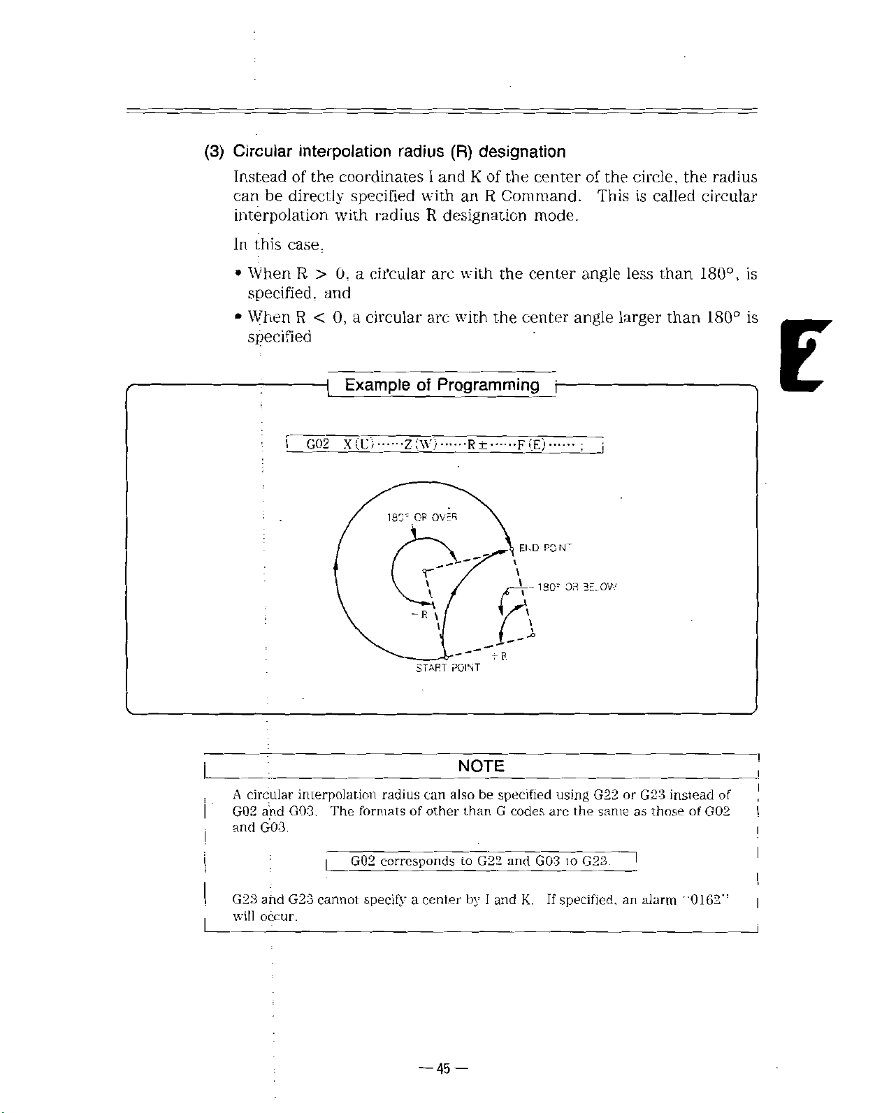
(3)
Circular
interpolation
radius
designation
(R)
Insteadofthe
directly
be
can
interpolation
In
this
case.
When
•
specified,
When
•
R
R
>
<
specified
:
I
GQ2
.
;
coordinatesIand
specified
with
0,
a
and
a
0,
Example
(U)
X
radius
circular
circular
180=
Z
of
;Wj
OR
-R
with
R
arc
r
\
of
K
the
center
R
an
Command.
designation
arc
with
with
Programming
R±
......
OVER
\
\
......
the
the
mode.
center
center
F(E)
END
v
t
1
PO
180=
f
N~
angle
angle
3E.OW
OR
of
the
This
circle,
is
less
larger
the
called
than
than
radius
circular
180°,
180°
is
is
E
&
T
than
to
by
specified
be
G
G22
and
1
R
codes
and
K.
using
G22
the
arc
G0310G23.
If
same
specified,
or
an
G23
as
alarm
instead
those
of
G02
"OieS'’
I
of
I
I
POINT
START
NOTE
and
G03.
and
occur.
interpolation
The
G03.
G23
cannot
formats
corresponds
G02
specify
radius
of
can
other
center
a
also
A
circular
,
I
G02
and
G23
will
—
45
—
Page 58

INTERPOLATION
2.4
(Cont’d)
2.4.5
Polar
In
that
Coordinate
processing
the
program
axis
to
case,
both
be
used.
|
G126;
|
G127;
C-axis
for
created
be
absolute
Interpolation
with
is
a
machining
easily
...
j
Polar
j...
Polar
linear
the
linear
axis
the
on
command
coordinate
coordinate
HYPOTHET
(G126,
axis
(X-axis)
orthogonal
workpiece
X-C
the
(X,
C)
interpolation
interpolation
CAL
t
G127)*
and
with
any
to
orthogonal
incremental
and
C'AX-S
C-AXIS
TOOL
/
rotary
the
X-axis.
shape
with
coordinate
mode
mode
On
Off
axis
(C-axis).
This
X-axis
the
system.
commands
X-AXIS
assume
enables
and
In
H)
(U:
a
C-
this
can
(1)
NOTE
G126
When
comes
absolute
of
dinate
regarding
ed
Before
Fig.
2.4.6
Command
instructed,
G126
in
is
effect
coordinate
interpolation
When
G126
the
is
instructed,
126
G
Coordinate
hypothetical
and
is
instructed,
is
current
the
System
polar
the
system
as
performed
position
must,
C-axis
46
—
—
Polar
of
Coordinate
coordinate
coordinate
origin
the
on
that
polar
be
coordinate
C-axisas“0.”
of
returnedtothe
interpolation
system
of
X-Y
plane.
origin
Interpolation
is
set
with
plane.
interpolation
absolute
of
Polar
coordinate
Mode
origin
the
is
system.
be¬
coor¬
start
Page 59
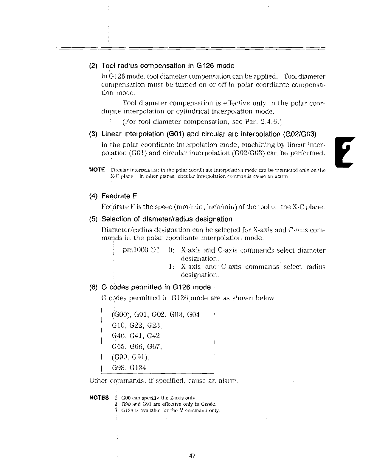
(2)
Tool
radius
compensation
in
G126
mode
126
In
G
compensation
tion
mode.
Tool
dinate
(3)
Linear
In
polation
NOTE
Feedrate
(4)
interpolation
:
(For
interpolation
polar
the
Circular
plane.
X-C
Feedrate
(5)
Selection
Diameter/radius
mands
in
mode,
tool
must
diameter
tool
diameter
coordiante
(G01)
interpolation
and
In
other
F
F
is
of
the
speed
the
diameter/radius
designation
polar
diameter
be
turned
compensation
cylindrical
or
compensation,
(G01)
and
interpolation
circular
polar
the
in
planes,
circular
(mm/min,
coordiante
compensation
on
off
or
is
effective
interpolation
circular
mode,
interpolation
coordinate
interpolation
interpolation
inch/min)
designation
can
be
selected
interpolation
applied.
be
can
polar
in
only
see
Par.
interpolation
arc
machining
(G02/G03)
mode
of
the
for
mode.
cause
X-axis
commands
coordiante
the
in
mode.
2.4.6.)
by
be
can
can
be
instructed
an
alarm.
tool
on
the
and
Tool
diameter
compensa¬
polar
coor¬
(G02/G03)
linear
C
inter¬
performed.
only
on
plane.
X-C
axis
com¬
the
E
(6)
G
G
r
I
j
Other
NOTES
pmlOOO
:
codes
codes
(GOO),
G10,
G40,
G65,
(G90,
G98,
permitted
permitted
G01,
G22,
G41,
G66,
G91).
G134
commands,
can
GOO
i.
and
2.
G90
3.
G134
is
D1
G02, G03,
G23,
G42
G67,
specified,
if
specifiy
are
G91
available
0:
1:
in
G126
in
G
the
Z-axis
effective
the
for
X-axis
and
designation.
X-axis
and
designation.
mode
126
mode
G04
cause
only.
only
M
Geode.
in
command
are
!
I
I
I
an
only.
C-axis
C-axis
shown
as
alarm.
commands
commands
below.
select
select
diameter
radius
—
47
—
Page 60

INTERPOLATION
2.4
(Cont’d)
r
|
|
i
I
|
I
!
I
i
!
00001
;
G98
T0101
GOO
G126
G01
G03
G01
G03
G01
G03
G01
G127
M30
(7)
;
;
X120.0
-
G42
XO
X—
X—
CO
X20.0
G40
;
:
25.0
40.0
;
-
X40.0
C40.0
X
120.0
—
Polar
When
coordinate
polar
shows
are
coordinate
the
The
coordinate
the
Whether
used
C
1-20.0
;
C25.0
120.0
sign
minus
polar
coordinate
can
Example
-
F100.0
K-15.0
;
-
;
-
-
minus
X-axis
of
specifications
coordinate
X
—
the
normal
be
selected
Programming
of
-
;
;
specifications
different
is
minus
X-axis
system
hypothetical
of
specifications
by
the
Positionedatthe
I
i
i
Turns
—
I
from
can
specifications
in
which
parameter
Turns
Polar
Shape
i
that
selected
be
programs
polar
on
coordinate
coordinate
processing
polar
off
C
or
coordinate
of
normal
by
plane
the
X
pm4019
point
start
state
is
are
minus
of
interpolation
interpolation
program
interpolation
machines,
parameter.
a
that
reversed.
created.
specifications
Dl.
machining
polar
sign
the
Fig.
2.4.7
of
Parameter
Fig.
2.4.7
pm4019
Specifications
Normal
Hypothetical
Polar
D1
(-)
C
1
Coordinate
—
48
=
=
x
;+!
Minus
—
1:
0:
minus
X
Normal
X
minus
O
Specification
specifications
specifications
Specifications
Hypothetical
Coordinate
)
(
+
X
System
Page 61

;
NOTE
—
(
When
arc
commands
(G41.
G42)
formed
Rotation
Lc
Normal
HYPCT
i.
I
NORMAL
1
Compensation
(G02.
are
that
with
Specifications
HELICAL
r
i
SPEC
-ICA'IONS
polar
the
coordinateXminus
GO-3)
reversed
fact
Direction
C
i
i
+
G<3
>
c
Direction
in
x
and
for
mind.
:
?
-
of
the
of
me
Diameter
specifications
compensation
normai
specifications.
Circular
X
minus
t
4-
Y
X
Compensation
selected,
arc
direction
Arc
Commands
Specifications
HYOPTHEOCAL
ic-nj
'w
SPEC.,
MINUS
-.CATIONS
the
rotation
f
o
diameter
Therefore,
C
i
!
+
X
programming
'
?
-
Commands
direction
compensation
\
circular
of
commands
be
must
per¬
E
is
the
plus
case
Normal
H'-FOT.-ET
\
NORMAL
Turn
the
in
of
Specifications
t
SPEC
the
on
case
X
minus
;
:•
C
CAL
+
)
G4J
—
)
---
=ICA~IONS
polar
normal
of
specifications.
:
;
4-
X
coordinate
polar
X
4
Specifications
minus
4VFCT-ETCA-
X
o-
L
—
----
l
X
interpolation
coordinate
M'NUS
SPEC'S
•:
!
C
+
G
42
041
1
---
x
•:
-
CA'IONS
inode
specifications,
when
X
coordinate
and
minus
in
—49—
Page 62

2.4
INTERPOLATION
(Cont’d)
1.
2.
3.
•
4.
5.
6.
7.
8.
126
and
polar
equipment
power
sure
G126
to
Instruct
G
the
structed.
The
at
Be
Prohibition
cannot
G126
Mirror
G98
tion
GOO
dinate
terpolation
GOO
In
X-C
Therefore,
image
(feed
mode..
(G
code
interpolation-mode.
can
polar
the
hypothetical
NOTES
and
G
127
are
coordinate
enters
on
per
be
at
and
cancel
mirror
of
instructed
be
cannot
minute)
including
mode.
instructed
coordinate
plane.
a
feed
in
G127
G
modal
interpolation
G127
reset.
nose
radius
image
when
applied
be
must
rapid
outside
interpolation
speed
on
G126
ON
single
a
codes
mode
(polar
coordinate
compensation
the
G
in
instructed
be
cycle)
feed
positioning,
For
the
X-C
the
X-C
and
block.
of
19
remains
mirror
126
cannot
plane.
mode,
plane
G127:
group.
mode;
in
interpolation
When
on
interpolation
before
image
an
the
polar
instructed
be
cancel
be
must
G1
until
the
instructing
mode
is
alarm
would
coordinate
polar
the
performed
is
instructed.
instructed,
is
26
G127
next
mode
G126.
on.
occur.
the
polar
in
coordinate
is
in¬
off)
state
interpola¬
coor¬
in¬
on
the
9.
Circular
by
T,
10.
T
can
The
11.
In
12.
Programs
13.
However,
interpolation
Since
14.
of
483
commands
I
and
C-axis
andMcommands
S,
and
S
cannot
be
instructed.
spindle
the
polar
function
coordinate
cannot
programs
mode.
C-axis
the
coordinate
speed
“command
in
the
by
K
to
instructed
be
is
interpolation
restartedinthe
be
can
becomes
is
specified
in
error
polar
coordinate
represent
the
polar
in
the
disabledinthe
mode,
be
restarted
in
infinite
in
polar
the
polar
the
coordinate
interpolation
addressofcircle
coordiante
polar
manual
polar
range
a
coordiante
coordinate
containing
interpolation
absolute
whenacommand
coordinate
interpolation
interpolation
specify
mode
center.
mode.
interpolation
is
fixed
interpolation
polar
pass
coordinate
the
mode,
the
to
mode”.
X-axis
mode.
to
OFF.
mode.
center
Alarm
M
—
50
—
Page 63
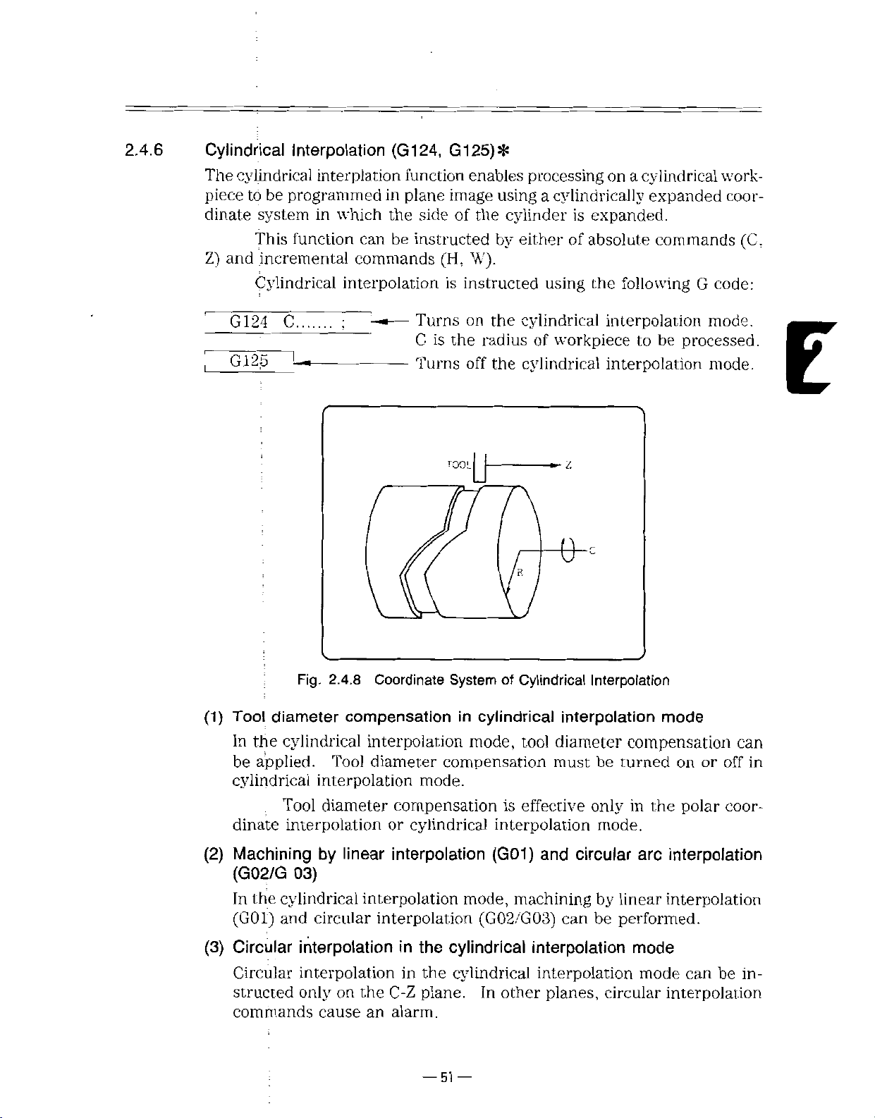
2.4.6
Cylindrical
cylindrical
The
piece
dinate
and
Z)
to
be
system
This
incremental
Cylindrical
Interpolation
interplation
programmed
in
which
function
can
commands
interpolation
(G124,
function
plane
in
the
sideofthe
be
instructed
G125)*
enables
image
(H,
W).
is
instructed
processing
using
cylinder
by
either
cylindrically
a
expanded.
is
of
absolute
using
the
on
cylindrical
a
following
expanded
commands
G
code:
work-
coor¬
(C,
,
(1)
G124
G125
Tool
C.
Fig.
diameter
2.4.8
Coordinate
compensation
Turns
C
is
Turns
TOOL
on
the
radius
off
System
cylindrical
in
cylindrical
the
cylindrical
the
of
Cylindrical
workpiece
of
tH
interpolation
interpolation
be
to
interpolation
Interpolation
mode.
processed.
mode.
z
mode
In
be
cylindrical
dinate
Machining
(2)
(G02/G
In
(G01)
(3)
Circular
Circular
structed
commands
cylindrical
the
applied.
Tool
interpolation
03)
the
cylindrical
and
interpolation
Tool
diameter
interpolation
diameter
by
linear
interpolation
circular
interpolation
interpolation
interpolation
only
on
the
cause
an
mode,
compensation
mode.
compensation
cylindrical
or
interpolation
mode,
in
in
C-Z
alarm.
cylindrical
the
the
plane.
51
—
cylindrical
—
tool
is
effective
interpolation
(G01)
(G02/G03)
and
machining
interpolation
interpolation
In
other
planes,
diameter
must
be
only
mode.
circular
by
can
be
circular
compensation
turned
the
in
arc
linear
performed.
mode
mode
or
on
polar
interpolation
interpolation
can
interpolation
can
off
coor¬
be
in
in¬
Page 64

2.4
INTERPOLATION
(Cont’d)
Feedrate
(4)
FeedrateFis
G
(5)
G.
,
I
j
|
,
codes
codes
(GOO),
G10.
G40,
G65,
(G90.
G98.
Other
NOTES
F
the
permitted
permitted
G01,
G22, G23,
G41,
G66.
G02.
G42.
G67,
G91),
G134
commands,
can
1.
GOO
G90
and
2.
G134
is
available
speed
in
in
if
specify
G91
are
Example
-
(mm/min,
G124
G124
G03,
specified,
the
G04
X-axis
effective
the
for
mode
M
inch/min)
mode
are
cause
only.
only
G
ir.
command
Programming
of
as
an
code.
only.
of
shown
alarm.
the
tool
below.
f-
on
the
C
plane.
Z
0100
i
G98
1
TO
GOO
j
|
G124
.
G01
.
!
C60.0
Z32.5
|
•
C240.0
G03
|
G02
,
G01
|
,
G40
G125
|
M30
;
;
10
;
;
X44.0
C45.0
G42
;
120.0
C
;
Z40.0
Z47.5
C360.0
Z44.0
;
CO
-
Z47.5
;
C249.549
C259.099
;
;
-
-
—
F100
—
;
R7.B
R7.5
of
Positionedatthe
machining
cylindrical
on
,
;
I
;
cylindrical
off
point
stan
interpolation
interpolation
—
52
—
Page 65

r
!-
1.
Instruct
G124
NOTES
G125
and
in
ON
a
single
G124
block.
and
G125:
G
2.
124
cylindrical
the
3.
The
power
4.
Be
sure
Prohibitionofmirror
5.
G124
Mirror
6.
Circular
dress
1
7.
G98
1
1
!
|
I
I
I
I
i
GOO
8.
cal
mode.
GOO
In
9.
hypothetical
Therefore,
T,
10.
T-
be
11.
The
interpolation
the
S,
and
instructed.
G
125
and
equipment
on
and
cancel
to
cannot
image
commands
radius
per
(feed
(G
code
can
and
spindle
instructed
be
cylindrical
a
M
cannot,
S
function
are
modal
interpolation
enters
at
reset.
nose
image
be
instructed
cannot
by
minute)
including
I
be
in
and
must
mode.
interpolation
plane.
speed
feed
commands
be
instructedinthe
is
G
codes
mode
remains
G125
(cylindrical
radius
applied
the
K.
rapid
For
outside
disabledinthe
compensation
when
in
cylindrical
Specify
instructed
be
feed
positioning,
the
mode,
on
the
the
cycle)
C-Z
group.
of
19
on
interpolation
mirror
mode;
G124
interpolation
a
radius
the
in
cannot
cancel
plane.
C-Z
interpolation
plane
must
cylindrical
cylindrical
When
until
the
before
image
an
value
cylindrical
be
the
be
interpolation
G
next
G125
mode
instructing
is
mode
alarm
would
mode
cannot
directly
interpolation
instructedinthe
cylindrical
is
performed
instructed.
interpolation
124
is
is
off)
on.
by
address
interpolation
mode.
mode.
instructed,
instructed.
state
G126.
occur.
specify
ad¬
R.
mode.
cylindri-
the
on
M
C-Z
can
at
E
!
i
I
be
restarted
mode,
in
the
manual
cylindrical
range
in
a
absolute
interpolation
containing
is
fixed
the
OFF.
to
mode.
cylindrical
in-
mode.
interpolation
be
restarted
can
12.
In
'
'
1
13.
Programs
However,
terpolation
cylindrical
the
!
cannot
programs
53
Page 66

INTERPOLATION
2.4
(Cont’d)
2.4.7
Tool
Diameter
Interpolation
(1)
Automatic
using
Bv
by
Specifying
(2)
A
the
Specifying
(3)
The
j
.
|
|
Compensation
(4)
the
tool
radius
offset
following
G41
G42
G40
specified
(left
(right
Compensation
Cylindrical
and
offset
tool
tool
number
tool
of
diameter
radius
radius
is
stored
diameter
codes
G
compensation)
compensation)
I
plane
Functions
Interpolation
path
tool
compensation,
the
of
in
tool
by
T
code.-
compensation
are
used
tool
offset
Set
!
tool
(rotary
memory
control
tool
for
Turns
tion
Turns
tion
Available
path
can
tool)
and
R
point
G
by
mode
mode
code
diameter
tool,
on
on.
tool
off
off.
in
Polar
automatically
be
be
to
used.
given
is
to
compensation:
by
zero.
diameter
diameter
Coordinate
offset
specifying
compensa¬
compensa¬
Compensation
plane:
X-C-
plane:
C-Z
Entry
(5)
When
fective.
next
the
advance
In
In
diameter
tool
to
G41orG42
The
direction
G41
to
or
direction
planes
polar
cylindrical
G42,
are:
coordinate
instructed,
is
of
offset
and
interpolation
interpolation
compensation
the
the
on
is
compensation
by
an
offset
mode
mode
compensation
applied
is
of
by
normal
quantity
mode,.
start
the
to
G41
mode
point
the
or
G42.
becomes
of
or
left
block
a
right
ef¬
in
—
54
—
Page 67

Behaviorintool
(6)
diameter
compensation
mode
Upon
along
the
part
blocks:
(a)
;
entry
the
Since
program
The
Inside
to
offset
the
tool
corner
the
compensation
path
until
path
is
only
has
path
is
controlled
(180°
mode
G40
is
automatically
specify
to
as
G01
or
less):
Intersection
by
G41orG42.
instructed.
computed
shape
the
follows
by
G01
by
the
of
the
angle
the
calculation
the
tool
equipment,
NC
workpiece.
between
expression
moves
angle
E
M97:
(7)
Canceling
compensation
The
’
of
the
Compensation
(
8
)
The
tool
drical
(9)
Turning
Turn
interpolation
Changing
(10)
tool
A
tion
Intersection
caicuiatior.
tool
When
last
interpolation
on
G40
block
modes
diameter
on
or
off
off
or
the
mode
tool
diameter
mode
is
on.
mode
(b)
Fig.
diameter
modeiscanceled
is
of
compensation
instructed,
compensation
enabling
compensation
mode
the
tool
or
diameter
cannot
or
tool
diameter
diameter
polar
changed
be
Outside
2.4.9
polar
coordinate
corner
Tool
tool
the
mode.
the
tool
functions
coordinate
compensation
when
M96:
Circular
Path
by
G40.
positioned
is
diameter
are
compensation
available
interpolation
compensation
mode
interpolation
the
tool
round
arc
the
at
only
mode
the
in
mode.
diameter
mode
point
start
functions
cylin¬
the
in
mode.
cylindrical
compensa¬
—
55
—
Page 68

2.5
FEED
FUNCTIONS
2.5.1
Rapid
The
for
traverse
is
Traverse
rapid
the
motion
determined
Motion
axis
are
For
basic
a
by
parameters
rapid
parameter
parameters:
For
2000
pm
to
pm2000
pm2000
Range
j
j—
For
(1)
tiple
traverse
for
defined
rate
by
paths
reached
override
traverse
(pm2447).
(pm2448,
either
Fo.
D3
D3
D3=l=Fo
of
setting
each
axis,
of
0.001
Rate
motion
manual
independently
your
machine
are
different
at.
rapid
of
rates,
Fi,
Fo,
pm2449).
setting
setting.
=
0=Fo
rapid
rapid
mm/min
is
used
rapid
normally
times
traverse
are
levels
Six
25%,.
F2,
unit
(pm2447)
(pm2447)
traverse
traverse
(deg/min).
for
the
traverse
(RAPID).
for
each
manufacturer
straight
not
independent
by
rates,
available.
rapid
of
50%,
and
mm/min
setting
setting
rates
can
rates
motion
axis.
because
25%,
Fo,
Fo
is
traverse
100%.
%
or
unit:
unit:
-
,
be
for
The
and
constant
a
can
mm/min
%
set
positioning
tool
rapid
The
preset
the
end
motion.
axis
50%,
and
override
and
Fi
selected
be
some
at
(GOO)
movesata
traverse
each
for
points
100%
feedrate
can
Fa
be
are
defined
according
-
suitable
and
rapid
rate
axis.
of
each
of
set
set
mul¬
the
by
in
2.5.2
(2)
NOTE
The
I
|
Cutting
digits
With
(mm/min)
lation
(G02,
Two
specifying
for
before
instructing
maximum
Machine
by
the
ed
Feed
following
programmed
are
G03).
types
the
programmable
have
their
tools
machine
address
of
feedrate
feed
function
F
andEcodes.
Table
G
code
G99
G98
own
builder.
tool
characters
at
specifications
2.5.1
optimum
linear
shown
G
Feed
Feed
Feed
rapid
traverse
rapid
traverse
F
and
interpolation
can
Table
in
Specifying
Codes
for
Function
Meaning
per
rotation
per
minute
rate
rates.
tool
E,
(G01)
be
selected
2.5.1
(mm/rev)
(mm/min)
is
240,
Refer
to
feedrates
circular
or
using
Specify
.
000
mm/min.
the
manual
per
.
the
theGcodes
provid¬
minute
interpo¬
codes
G
For
details
of
the
G
code
functions,
—
56
—
see
Par.
2.5.3.
Page 69

(1)
and
E
until
F
tive
between
newly.
codes
the
G98
not
If
modal,
are
time
next
G99
and
instructed,
and
or
F
an
is
performed,
alarm
once
E
“0370”
they
code
an
instructed,
are
is
instructed.
F
or
E
will
code
occur.
must
they
When
be
effec¬
are
switching
instructed
2.5.2.
(2)
1
Feed
(1)
feed-per-minute
In
structed,
If
ed.
With
or
in
per
rotation
numeric
a
inch/rev)
per
(G99
value
spindle
(mm/rnin)
alarm
mode)
following
specification,
“0371”
rotation
an
address
can
will
occur.
specified.
be
E
code
cannot
F
or
E,
tool
be
feedrate
instruct¬
(mm/rev
E
Table
Table
;
Metric
Input
Inch
Input.
2.5.2
2.5.2
|
shows
Range
Metric
input
Inch
input
Metric
input
Inch
input
range
the
of
Feed-per-Rotation
Format
F33
F.34
F24
E2f>
F33
E34
F24
E26
F
of
andEcode
F
E
and
Feed-per-rotation
I
F0.001
|
E0.0001toE500.0000
F0.0001
EO.OOOOO
I
|
F0.001
EQ.OOOl
FO-0001
000001
E0.
Code
to
FaOO-OOO
to
F19.0850
I
E
19.685000
to
F1270.000
to
E1270.0000
to
F50.0000
to
specification.
Specification
specification
mm/rev
in/rev
mnt/rev
in
E50.
000000
mm/rev
in/rev
mm/rev
rev
in
range
rev
Table
2.5.3
shows
Table
Metric
Inch
NOTES
limits
2.5.3
output
output
I
2.
.
by
spindle
F
(E)
Specification
Spindle
X
values
The
limitedbythe
Follow
manual.
—
axis
F
F
speed
shown
limit
the
57
Rotation
x
(E)
x
(E)
limit
values
machine
—
rotation
speed.
Limits
Rate
value
Limit
Sg
240,000
Sg
24.000
values
in
the
per
conditionsofmachines.
mra/min
in/min
are
one-half
above
table.
minute
tool
manufacturer's
arc
further
by
of
the
Page 70

2.5
FEED
FUNCTIONS
(Cont’d)
G99
I
G01
I
F
S1000
U60.
=
x
0.5m
S
=
500mm/min
=
(2)
3002
J
T
Fig.
F
command
direction
(r/min)
W40.
4002
+
2.5.1
x
X-AXIS
m/rev
linear
for
tangential
;
F0.5
;
lOOOr/min
Z-AXIS
•
COMPONENT
SPEED
F
Command
circular
and
the
to
SPEED
COMPONENT
in
Simultaneous
(Feed
motion
per
Rotation)
interpolation
path.
-X
Two-Axis
Linear
specifies
400
mm/
Interpolation
feedrates
i
300
mm/min
ir.:n
in
the
G99
G03
S1000
.....
U
(r/min).;
W
I
F0.2
.....
.....
CENTER
200
nun/run
*
x
=
0.2x1000
S
F
(mm/rev)
=
fx2
J
Fig.
fz2
+
2.5.2
1.
If
Do
2.
3.
Feedrate
=
200mm/min
(r/min)
F
Command
programmed,
F0
is
program
not
in
F
the
‘
in
Simultaneous
(Feed
is
it
commands
direction
X-axis
Rotation)
per
NOTES
regarded
with
are
—58—
Two-Axis
an
as
minus
rates
+x
Circular
input
error.
numerals;
obtained
-rZ
Interpolation
alarm
“0102”
by
radius
f.
will
values.
it
occur.
Page 71

2.
5.
2.
Feed
2
per
minute
(G98
mode)
With
(1)
or
parameter
pm2G04
DO
0
-
pm2004
!
DO
-
NOTES
inch
!
I
Metric
ouiput-
i
.
output
Metric
outpul
|
Inch
'
output
2.
.
numeric
a
F60
Table
Table
]ncÿ
X-axis
1.
The
Refer
/mm)
format
pm2004
Metric
inch
Metric
|
;ncfj
;
Metric
j
Inch
I
Metric
.
|nch
|
speed
limit
to
per
2.5.4
2.5.4
input
ir.put
ir.put
;r,put
ir.put
input
input
uipin
values
the
value
minute
or
shows
Range
Format
F60
F52
F60
F52
F63
F54
F63
F54
values
limit
per
machine
following
F63
DO.
FI
F0.01
FI
F0.01
F0.001
FO.OOul
F0.001
F0.0001
are
minute
tool
address
an
specified.
be
can
format
the
of
Feed-per-Minute
Linear
Feed-per
to
to
one-half
are
manufacturer’s
(at
range
Axis
r-ir.uie
F240000
to
F94488.18
F609600
F24000.00
to
F240000.00
to
to
F94488.189U
to
F609600.000
F24000.0000
to
of
further
Specification
mm/min
mm/min
the
limited
metric
F
of
in/min
in/min
mm/min
values
manual.
F,
tool
feedrate
input)
specification.
code
Code
F
Range
in/min
mm/min
in/min
showninthe
by
the
Specification
Rotary
Feed
FI
to
|
'
F0.01toF240000.00
to
FI
!
F0.01toF240000.00
F0.00ItoF240000.000
F0.0001
F0.001
|
F0.0001
'
conditionsofmachines.
can
be
Axis
per-minuie
F240000
F240000
to
F240000.0000
F'240000.000
to
to
F24000.0000
above
minute
(mm
selected
Specification
dcg/min
_
deg/min
deg/min
deg'
deg/min
deg/min
deg/mir.
table.
by
Range
E
min
deg'min
F
(2)
command
control
path.
G98
;
U60.W40.F500.
G01
F-500-
(mm/min)
X-AXIS
Fig.
specifies
3002
i
i
SPEED
2.5.3
linear
for
and
feedrates
:
4002
+
i
i
Z-AXiS
SPEED
COMPONENT
COMPONENT
F
Command
in
circular
in
interpolation
the
Simultaneous
per
(Feed
Minute)
direction
TX
Two-Axis
simultaneous
at
tangential
\
:
400
min
mm/
Linear
Interpolation
300
to
mm/
two-axis
the
min
motion
—59—
Page 72

2.5
FEED
FUNCTIONS
(Cont’d)
G98
G03
F
Fig:
(3)
:
F200.;
I
.....
Z
.....
.....
fz2
fx2
N;
+
=
200=
X
(mm/min)
F
2.5.4
1.
If
2.
Do
3.
Feedrates
F
command
fied
Command
programmed,
F0
is
program
not
in
feedrates
F
the
interpolation
for
in
in
Simultaneous
(Feed
is
it
commands
X-axis
the
direction
diraction
Minute)
per
NOTES
regarded
with
are
at
Two-Axis
input
as
an
minus
numerals;
obtainedbyradius
rates
rotary
the
tangential
CENTER
+x
Circular
error.
alarm
linear
and
to
the
K
200
Interpolation
“0102”
axes
motion
mm/rr.'n
will
values.
control
path.
'fx
occur.
speci¬
G98:
G01
Metric
a)
Distance
Time
Inch
b)
Distance
W10.
input
=
input
H60.
F100.;
(F6.0)
=
10002
v
AXIS
Z
COMPONENT
+
SPEED
AXIS
C
COMPONENT
60827.625
100000
(F5.2)
=
1000002+600002
V
A
Z
+
L
60000*
i
=
C-AXIS
COMPONENT
=
SPEED
0.6082
i
SPEED
*
-v
C
60827,625
=
(min)
1166190,0379
-
36.5
F-00.
60.
(s)
mm/Tnin
deg
10.
rrnr
Time
1166190.0379
=
1000000
—
=
60
0.1166
(min)
=
6.9
(s)
Page 73
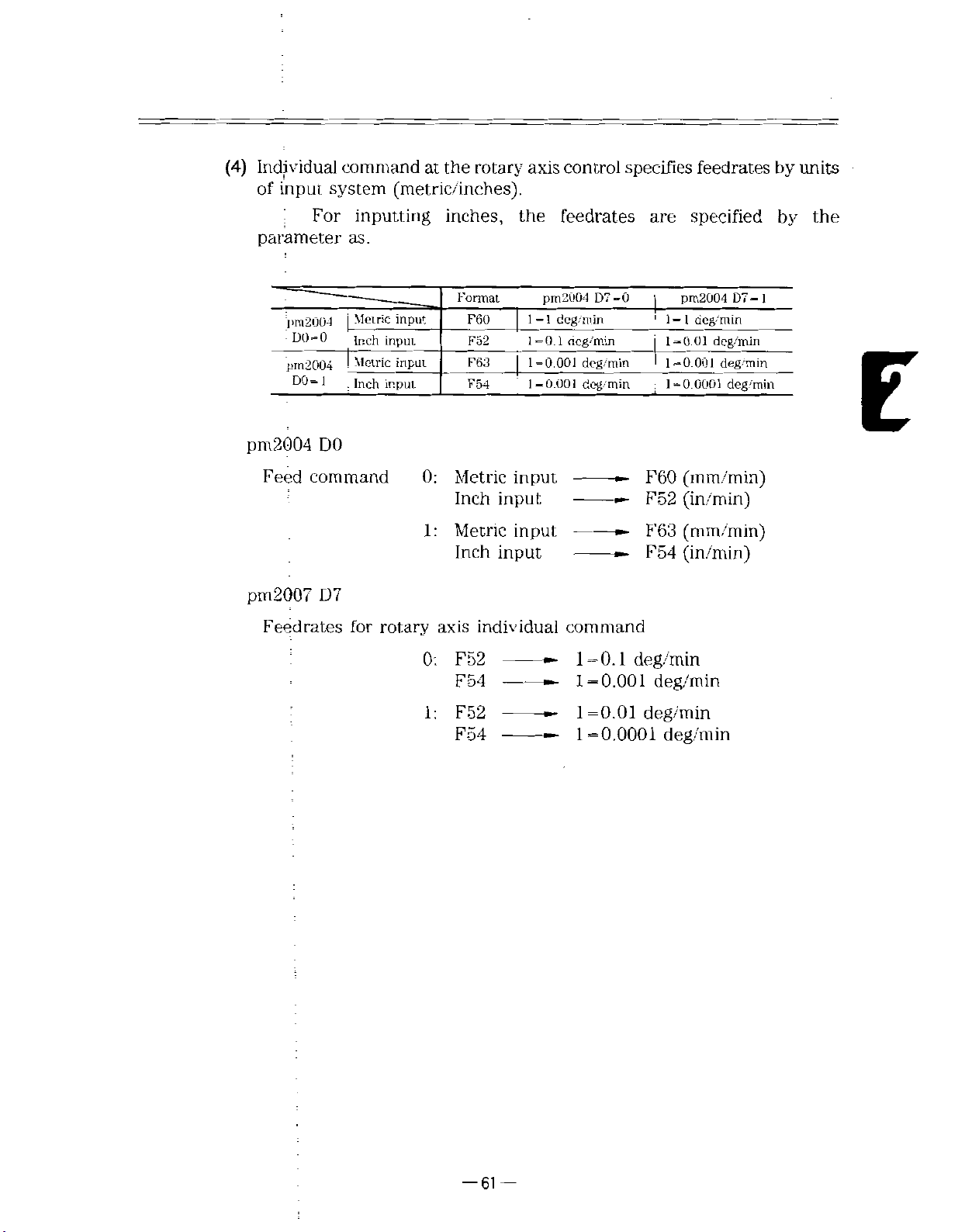
(4)
Individual
of
parameter
input
commandatthe
system
For
(metric/inches).
inputting
as.
rotary
inches,
axis
the
control
specifies
feedrates
are
feedrates
specified
by
by
units
the
pm2004
:
DO=O
pm2004
D0-1
pm
2004
Feed
pm2007
Feedrates
Metric
|
Inch
Metric
Inch
DO
command
D7
for
input
input
input
input
rotary
0:
1:
0:
1:
Format
Metric
Inch
Metric
Inch
axis
F52
F54
F52
F54
F60
F52
F63
F54
j
input
input
input
input
individual
pm2004
deg/min
1-1
1=0.1
1=0.001
1-0.001
command
D7-0
(lcg'min
deg/min
deg/min
1=0.1
=
1
0.001
1=0.01
1=0.0001
pm2004
=
1
1
1-0.01
1=0.001
'
,
1=0.0001
F60
(mm/min)
F52
(in/m
F63
(mm/min)
F54
(in/min)
deg/min
deg/min
deg/min
deg/min
deg/min
deg
deg/min
deg/min
in)
D7
min
1
-
E
i
-61
—
Page 74

2.5
FEED
FUNCTIONS
(Cont’d)
2.5.3
Switching
(E)
,
;
G
code
G98
These
F
(1)
This
minute.
(2)
This
rotation.
between
for
;
specify
feeding.
,
codes
command
command
Feed
feeding
executes
executes
per
Minute
per
subsequently
Table
Metric
Inch
2.5.5
G98
G98
input
input
subsequently
Table'
Metric
Inch
2.5.6
G99
G99
input
input
and
minute
Meaning
Code
Meaning
Code
Feed
feeding
or
issued
Meaning
mir./min
in/min
issued
Meaning
mm/rev
in/rev
of
of
per
F
F
.
(E)
Rotation
per
rotation
codes
codes
(G98/G99)
before
feeding
as
feeding
as
the
per
per
(3)
G98
G98
changed.
(4)
Specification
Switching
ly.
F
(E)
Switching
(5)
The
G99
and
G99
and
‘
between
Therefore,
code.
of
initial
state
modal
are
modal
are
switching
at
G98
whenever
initial
power
at
Table
state
pm4000
pm-4000
G
codes.
codes
G
between
G99
and
switching
the
power
at
on
2.5.7
Initial
Parameter
D2-0
D2-1
and
G98
cancels
on
can
be
set
Parameter
State
effective
G99
and
code
F
(E)
has
been
G98orG99
to
pm4000
InitialGcode
and
G98
G99
until
specified
made,
specification
previous¬
be
sure
to
by
parameters.
is
specify
—
62
—
Page 75

2.5.4
Screw
Cutting
and
Continuous
Screw
Cutting
(G32)
G-32
With
by
cut
dinate
Range
(1)
Table
Metric
Output
Inch
Input
NOTE
Direction
(2)
X
this
command,
lead
a
(X,
Table
I
Metric
i
inPut
;|
:
Inch
i!
output
Metric
input
inch
input
The
The
(U)
.......
Z)
covered
2.5.8
2.5.8
F
code
E
codeisused
Z
specified
point
or
by
shows
Range
F
ormat
F33
E34
F24
E26
F33
E34
F24
E26
is
used
screw
of
(W)
straight
a
incremental
for
for
F(E).
......
in
an
and
F
the
of
F
normal
precise
screw,
or
F
E
range
E
and
Range
F0.001toF-500.000
E0.0001
F0.0001
E0.
F0.001
E0.0003
F0.001
E0.
screw
screw
taper
code
E
position
codes
F
of
Codes
of
ard
F
to
to
000004
F1270.000
to
to
F50
to
000010toE50.
cutting.
cutting.
J
screw,
all
the
(U,
E
and
E
EoOO.OOOO
FI
to
E
codes
for
Screw
Specification
9.
6850
FI
9.685000
1270.0000
0000
000000
lead
mm
in
mm
in
and
way
point.
W)
specifying
Cutting
for
Screw
mm
in
mm
in
scroll
the
to
Cutting
screw
absolute
screw
can
coor
lead.
be
E
Table
2.5.9
Condition
(X,
-X
shows
ZY
13-
I
-
45°
45°
of
Lead
r
I
U
-
r—
Screw
lead
Direction
Direction
Specifies
Specifies
,V
POINT!
w
—
—
I.
Cutting
specified
lead
lead
i
i
T*
I
p-
X
FAD:
it
the
direction
Table
taper
of
1
+x
angle
a
a
>
2.5.9
41
Fig.
2.5.5
in
in
of
by
screw
Z-axis
X-
axis
F
and
lead
direction.
direction.
E
codes.
—
63
—
Page 76

2.5
FEED
FUNCTIONS
(Cont’d)
(3)
(4)
Limit
F
and
shown
The
upper
Screw
Table
values
E
in
by
specifications
code
Table
Metric
Inch
limit
specification
2.5.11
Straight
Taper
Scroll
shows
Type
screw
screw
screw
spindle
2.5.10.
Table
output
output
X-axis
of
the
Table
screw
of
rotation,
2.5.10
Spindle
speed
methods
2.5.11
Normal
Precise
Normal
Precise
'
Normal
'i
Precise
speed
limited
are
Limit
Rotation
x
F
(E)
F
(E)xSg
component
Screw
S
by
Values
Speed
Limit
value
Sg
240,000
24,000
specifying
for
Specification
G32
Z(\V)...F...
G32
Z(Wi,.E
G32
X(U).-Z(W)...F.-
G32
X(U)...Z(\V),..E...
G32
X(L')...F...
G32
\(U)...E...
spindle
by
S
mm/min
in/minin
one-half
is
individual
Specification
;
:
...
;
;
rotation
of
;
;
speed
above.
the
screws.
S
as
Straight
•
I
Cutting
G00
G32
GOO
G32
GOO
Screw
U42.
W—
U
W
U—
W—
U
:
screw
lead
quantity
F-5.0
68.
42.
;
68.
;
44.
;
;
68.
;
44.
L
S:
5
--
=
5.0mm
=
5.0mm
=
2
3.
=
1.0mm
:
0mm
i
!
j
-x
r
CD!
20.
0
0
-<>
I
|*WWWAV>
so
—
64
—
Page 77

Taper
•
screw
Example
Programming
of
(ÿ
I
|
Cutting
GOO
|
1
G32
i
GOO
!
|
G32
1
GOO
Screw
quantity-
X13.
X38.
X60.
W35.
Xll.
X36.
X60.
:
(5)
.
W—
;
;
'
;
W—
;
:
be
=
L
=
1
5
3.
8
2=
2.0mm
1.0mm
35.
35.
this
specified
4.0mm
F4.0
;
equipment
lead
Continuous
Since
can
0mm
screw
:
as
cutting
has
shown
fast
in
1
buffer
Fig.
x
+
Cl
registers,
2.5.6.
A
1
continuous
I
•CD
cU5.
screw
z
cutting
G33
(G32)
(G32)
:
i
(a)
X(U).,.Z(W)...F(E)...
X(U)...Z(W)...
X(U)...Z(W)...
T'
St
;
3>
toj
Improved
screws
NOTE
pipe
Since
can
Do
not
had
screw
coupling
Fig.
a
stop
be
cut
change
cutting
screw
;
-
—
-
—
2.5.6
time
smoothly.
lead
would
Continuous
between
specification
occur
in
T©
the
<D
(D
K
Screw
screw
ForE
neighborhood
Cutting
cutting
midway:
s:i'
(b)
Worm
of
blocks
this
if
block
1
screw
were
joints.
is
done.
zero,
continuous
65
—
Page 78

2.5
FEED
FUNCTIONS
(6)
Slack
in
(Cont’d)
imperfect
screw
portion
(5.i,
.6
2)
The
Table
6:
.
a
slacks
2.5.12.
Table
Approximate
,
a
a,
>
T.\
Fig.
2.5.7
and
2.5.12
K
5i
expression
(In
—
5i
>
60*K
L*S
60*
O':
Slack
.
obtained
are
Slacks
in
1)
-
--
A/\/\/\/\/\y
Imperfect
in
Imperfect
.
L(mm):
j
S
(rpm):
K:
):
a(—
i
In:
by
the
Screw
Screw
Spindle
Constant.'.
Screw
Natural
0,
Screw
Portion
approximate
Portion
Meaning
lead
rotation
Usually
precision
....
£L
(Lead
L
logarithm
-rZ
speed
30
error)
(log
expression
e)
in
(In
—
(Example
Screw
Spindle
Screw
1
5
and
;
6
>
b>
>
a
1
1)
-
--
of
computation)
L
lead
speed
precision
are
8i
L#S
3.0
(In—
x
500
60»K
60-K
L»K
60-K
1/50j1/100
2.91
=
S:
mm
3.0
50
r/min
1/100
—
obtained
--
x3.61
x
3.0
60«K
3.61
as
1)
500
1/150
I
4.01
i
follows
=
3.0mm
=
0.83mm
I
1/200
4.29
when
.
1/250
1
4.52,4.70
the
above
1/300
conditions
are
given:
—
66
—
Page 79

NOTES
ON
G32:
.
1
Howtotake
Since
by
8
imperfect
in
Spindle
2.
The
terminated.
delay.
3.
Screw
G32
quired,
up
a
lead
error
8
and
1
in
screw
TH:
rotation
spindle
specification
rotation
Otherwise,
rounding-off
use
G92
slack
Fig.
Fig.
(*
occurs
2.5.8
portions.
+x
2.5.8
speed
speed
in
does
or
in
imperfect
at
must,
Start
must
the
G32
specification
permit,
not
G76).
the
start
be
taken
f
-«J*U
KWAWAV
J
and
be
precision
screw
screw
and
.
End
constant
may
rounding-off.
portion
of
end
See
(6)
V
I£L
of
Screw
until
not
screw
howtotake
for
i
Cutting
the
maintained
be
cutting,
+z
cutting
If
rounding-off
of
due
slack
up
one
to
shown
the
screw
a
servo
is
slack
z
is
re¬
4.
Operation
Th’e
iFeed
a.
b.
5.
Screw
Screw
insturcted,
6.
Screw
Screw
tinuous
7.
M
Do
issued,
screws
disregarded
following
override
Temporary7
cutting
cutting
Alarm
cutting
cutting
speed.
code
command
not
issue
program
the
could
operations
operation
stop
(FEED
G32
in
G32
must
“0452”
command
commands
continuous
would
be
not
cut.
during
including
G98
not
during
during
screw
screw
Regarded
...
HOLD)
mode
be
instructed
occur.
will
cutting
wait,
for
G32
operation
dry
run
dry
run
a
start
cutting
disregarded
are
100%
as
in
G98
specify
commands
point,
(feed
movement
with
in
that
during
per
M
block
screw
minute)
at
a
code
and
cutting:
mode.
manual
specified.
continuous
If
con¬
If
i
i
—
—
67
Page 80

2.5
FEED
FUNCTIONS
(Confd)
2.5.5
Multiple
Multiple
without
Since
the
ways
pulse
dle
angle
pulse
spindle,
the
A
after
point
to
performed
Thread
thread
shifting
screw
(one
a
same
multiple
by
feeding
generator,
the
Screw
screws
cutting
a
cutting
pulse
cutting
screws
and
thread
then
point
start
Cutting
(having
Fig.
2.5.9
per
rotation)
start
screw
synchronized
feeding
(G32)*
more
position.
start
Double-Threaded
operation
point
thus
can
is
pulse
from
cut
is
started
is
emitted.
than
I'
starts
on
be
in
with
one
LEAD
I
\\V
feed
spindle
the
workpiece
the
cut.
such
a
start
after
thread
in
w
\
A
Screw
synchronously
pulse
circumference
way.
point
spindle
that
pulse
a
the
a
lead)
with
generator
screw
from
revolves
be
can
a
attached
cutting
the
given
a
cut
start
is
al¬
is
spin¬
G32
,
With
point
from
(1)
(2)
X(U)
command,
this
pulse
X
(U)
Address
Least
j
Command
!
When
TheBcommand
issued.
is
it
Number
cutting
A
of
the
number
the
F(E)
.......
spindle
in
reyolves
pulse
a
with
multiple
the
Z
(W)
specified
B
Z(W)
the
spindle
point
.......
from
to
B...
;
.......
the
generator,
specified
lead
thread
j
angle
then
by
screw
____
=
l°
screw
(360°)
I
is
input
decimal
threads
of
start
points
of
increment
range
point
non
is
point
which
in
threads.
0.001°
0gB<360.00
input
-modal
multiple
of
on
the
the
is
used,
and
workpiece
circumference
Bl
effective
is
thread
circumference
specified
screw
the
cutting
set.
only
in
B
and
is
in
B
after
cutting
F
or
command.
E
the
blockinwhich
command
normally
is
divided
equally
a
is
started
on
start.
one
by
—
68
—
Page 81

:
r;
NC
3*8C
r
=c
SCÿrVV
2
CCMMiJC
y
CUT"
A--
\G
>-ct
HrEACrD
R?.S'
‘-tEC
3ECDC
"u
SC
T*--EAD.
T.nres-th'eacsd
i>;
Screw
ST
20'
1
NO
324C
PONT
SC-.E
i
i
C3WAN0
6
3‘2C
CL:7T.;'»G
Cf
/f
rC-JP-
WADEC
/
rt
;
=3:
THREAD
SECOND
THJC
"i
rCLCT|-
STA?.T
=»C.r
SCREW
3-4,
/
NOBCOVVAND
BSC
IB?=AD
SC
7-i=>EiC
TH.3EAC
E?70
rcur-:h-eaaed
fc;
0=
6*33
Sere*
x-i;
sc
'
D03.r
/
.-'C5T
THREAD
SECOND
THREAD
j
:a)
DoLble-:nreadec
See*
Fig.
2.5.10
NumberofThreads
Command
Screw
and
B
of
Multiple-Thread
E
—
69
—
Page 82
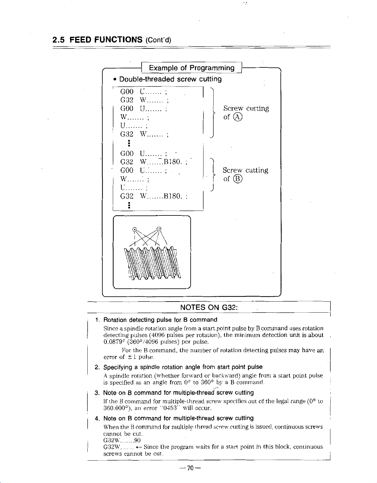
2.5
FEED
FUNCTIONS
Double-threaded
•
(Cont'd)
Example
I
of
Programming
screw
cutting
GOO
G32
GOO
W
U.
W
U.
U.
G-32
W
:
GOO
G-32
GOO
W
U..
W.
u.:
u
G32
W
.......
:
4
111
B180.
B180.
\
Screw
cutting
Of©
;
Screw
cutting
Of®
J
;
Rotation
1.
Since
detecting
0.0879°
error
Specifying
2.
spindle
A
specified
is
3.
Note
the
If
360.000°),
4.
Note
When
cannot
G32W.
G32W
screws
detecting
spindle
a
For
of
on
command
B
on
theBcommand
be
cannot
rotation
pulses
(360°/4096
±
B
B
(4096
B
the
command,
pulse.
1
spindle
a
rotation
angle
an
as
command
error
an
command
cut.
90
Since
be
for
for
pulse
angie
pulses
pulses)
rotation
(whether
from
multiple-thread
for
multiple-thread
“0453”
for
multiple-thread
multiple-thread
for
program
the
cut.
NOTES
B
command
a
from
per
rotation),
per
pulse.
number
the
angle
forward
to
0°
occur.
will
waits
—
70
—
ON
start
of
from
or
backward)
360°
screw
screw
for
G32:
point
the
rotation
start
by
a
screw
specifies
screw
a
start
by
pulse
minimum
detecting
pulse
point
angle
B
command.
cutting
out
cutting
cutting
point
B
command
from
of
issued,
is
in
detection
pulses
a
start
legal
the
continuous
block,
this
rotation
uses
unit
is
may
have
point
range
(0°
screws
continuous
about
an
pulse
to
j
Page 83

2.5.6
Variable
Lead
Screw
Cutting
(G34)*
;
this
quantity
the
;
Range
Least,
The
a.
(500
feedrate.
X(U)
command,
input
G34
With
by
(1)
Specification
Z(W)
of
K
of
specification
increment
range
speed
mm/rev
K
.......
variable
a
per
lead
Fig.
an
for
end
metric
at
F(E)...
.......
lead
rotation
in
variable
output
Variable
must
2.5.11
0.0001
(Metric
point
;
screw
the
of
mm/rev
input)
not
and
,
specified
screw.
Screw
Lead
screw
lead
or
0.00001
(Inch
exceed
50
inch/rev
by
address
cutting
inch/rev
input)
specification
the
for
K
inch
be
can
range
output)
cut
E
of
The
b.
c.
d.A;lead
accumulation
ceed
Lead
the
values
Table
change
Table
must
2.5.13
Movements
Metric
output
Inch
speeds
2.5.14
Metric
Inch
output
not
of
movements
shown
output
must
Upper
output
be
minus.
in
Upper
due
not
Table
Limit
to
exceed
Limit
due
to
2.15.3.
on
Accumulation
Changes
Upper
4194.303
419.4303
the
on
Lead
Upper
5.400
540
changes
Lead
in
limit
mm
in
values
Change
limit
mm/min
in/min
in
lead
of
shown
Speed
in
Table
must
ex¬
not
2.15.4.
—
71
—
Page 84

2.5
FEED
FUNCTIONS
(Cont’d)
Additional
(2)
Arithmetic
command
Limitation
The
a.
Table
The
b.
The
c.
ceed
explanation
expressions
K
on
command
feedrate
an
end
at
2.5.15.
,
Table
feedrate
•
2.5.15
Metric
Inch
at
output
output
an
accumulation.of
the
values
Table
2.5.16
Movements
Metric
Inch
output
shown
output
checking
for
point
Upper
end
movements
limit
point
in
Table
Upper
due
the
must
on
must
due
Limit
Changes
to
variable
exceed
not
Feedrate
'
Upper
in
m/rev
500
in/rev
50
not
be
changes
to
2.15.16,
on
Accumulation
in
Upper
4194.303
419.4303
at
limit
minus.
Lead
limit
nun
in
lead
End
-
-
screw
the
Point
in
of
values
lead
cutting
shown
must
(G34)
not
in
ex¬
Lead
d.
2.15.17.
Checking
F
:
K
:
W
:
S
:
N
:
—
=
N
change
limits
Fixed
Variable
Z-axis
Table
Metric
speeds
2.5.17
output
output
Inch
by
arithmetic
lead
lead
distance
(mmorinch)
Spindle
Spindle
end
(F+K/2)
point
rotation
rotation
'
+
must
Upper
command
command
(mm
(X-axis
speed
speed
(F-ÿ—
not
exceed
on
Limit
Lead
Upper
5400
540
expressions
(mm/rev
(mm/rev
or
inch)
distance
from
(r/min)
required
(rev)
K
)2+2
.
K
the
Change
limit
mm/ir.in
in-
min
or
inch/rev)
or
a
in
U
K
•
values
;
Speed
inch/rev)
start,
point
the
case
from
W
shown
to
of
start,
a
an
end
point
Table
in
point
end
screw)
to
an
—
72
—
Page 85

Limit
F-f
Limit
K
of
of
a
+
b
KNÿ
500.000
mm/rev
or
50.000
inch/rev
(F
+
Limit
-i-KN2ÿ
Limit
S/60
.
1
2.
3.
4.
of
1
of
•
Continuous
In
continuous
command
K
command
If
theKcommand
When
D1)
is
When
command
)2
+
c
4194.303
d
K
pulses
G34
the
to
set
parameter
the
is
2KW
5,400
block
block
break
command
,
1
the
0.001
0
>
mm
mm/min
screw
screw
at
exceeds
only
tool
(prnlOOO
mm/rev
or
cutting
cutting
block
the
is
issued
moves
or
419.4303
or
540
NOTES
by
the
variable
joints.
range,
legal
during
a
at
specified
DO)
is
set
0.0001
inch/rev.
inches
inch/min
lead
an
error
dry
run,
manual
1,
the
to
screw
"0450”
if
the
least
cutting
occurs.
parameter
continuous
input
increment
command,
(pm2000
feedrate.
of
E
K
5.
Address
Specifying
B
command
address
in
G34
block
a
in
b
G34
-73
block
—
causes
an
error
“04!50.’‘
Page 86

2.5
2.5.7
FEED
FUNCTIONS
Automatic
Accel/decel
Acceleration
for
(Cont’d)
rapid
and
traverse
Deceleration
cutting
and
feed
automatically
are
performed.
2.5.7.
1
Accel/decel
(1)
following
the
In
Positioning
•
Manual
•
Manual
•
Manual
•
of
rapid
operation,
(GOO)
rapid
continuous
traverse
handle
V
3
traverse
feeding
feeding
GOO
and
manual
pattern
the
(RAPID)
(JOG)
(HANDLE)
T'Mt
feed
of
automatic
—i
-
accel/decel
t
is
linear.
NOTE
Fig.
Rapid
rate
can
to
pm2808)
2.5.12
iraverse
be
set
Linear
rate
by
accel/decel
and
parameter.
Accel/decel
constant
(pm2461
Speed
of
pm2468,
to
rapid
traverse
pm2801
—
74
—
Page 87

2.5.
7.2
Accel/decel
(1)
Automatic
mode.
cutting
of
accel/deceloffeed
feed
v
Fs
2
a
motion
TiME
-
(G01-G03)
-
are
-
in
i
exponential
the
z
(2)
Feedrate
tapping,
set
(pm2501
to
The
tive
Do
time
time
by
parameters.
to
pm2838)
automatic
machines.
change
not
Fig.
2.5.13
constants
constants
pm2505.
accel/decel
setting
the
Exponential
and
feedreate
and
pm2511
parameters
unless
bias
to
NOTE
are
this
Accel/decel
bias
other
pm2515.
set.
the
to
required
is
are
set
than
pm2821
optimum
for
Speed
by
for
usual
special
parameters.
feedrate
pm2828,
to
for
values
purposes.
the
During
can
pm2831
respec¬
be
:
—
75
—
Page 88

2.5
FEED
FUNCTIONS
(Cont’d)
2.5.8
2.5.8.
1
Override
details
For
your
machine
Cutting
In
the
(1).
structed
10%
of
E
code,
If
(2)
the
selection
on
override,
tool
override
feed
automatic
by
the
from
However,
and
cannot
OVERRIDE
switch
Table
STEP
0
1
2
3
4
5
6
7
8
9
10
refer
manufacturer.
operation
E
code
or
F
to
200%.
0
the
feed
be
overridden.
CANCEL
and
runs
2.5.18
%
0
;10
20
30
40
50
60.
70
SO
90
100
Override
STEP
to
mode
can
by
switch
as
II
12
13
14
15
16
17
18
19
20
command
(TAPE.
be
overridden
tapping
is
on,
instructed
%
no
120
130
140
150
160
170
ISO
190
200
or
MEM,
cycle
the
by
reference
or
MDI),
21
in
as
instructed
is
is
feed
F
the
manuals
steps
not
or
E
OVERRIDE
CANCEL
.<§>
FEEDRATE
OVERRIDE
100
0
issued
the
feedrate
in
increments
by
affected
code.
200
%
the
by
F
this
by
in¬
or
-76-
Fig.
2.5.14
Override
Switch
Page 89

(3)
By
20%
from
option,
from
220
the
0
to
feedrate
540%
to
30
0%
.
and
In
can
this
in
be
overridden
case,
is
it
increments
in
32
overridden
40%
of
from
in
steps
in
increments
340
increments
of
20%
to
540%.
of
2.5.
8.
Table
2.5.19
STEP
22
23
24
25
26
27
Override
%
220
230
240
250
260
270
(Expanded
STEP
28
29
30
31
32
Type)
%
380
420
460
500
540
E
be
installed
by
DO
override
manual
Slops
Table
to
lo
1
2.5.18.
adjust
parameter
=
1
Fo
,
is
operation
are
21
the
optionally
the
traverse
pm2447.
speed
can
effective
as
same
to
override
set
be
in
both
(RAPID)
in
those
rapid
by
rate
%
in
for
automatic
mode).
traverse
25.
Fo,
rapid
operation
rate.
50,
and
traverse
(GOO
NOTE
Rapid
2
(1)
(2)
traverse
The.
This
switch
switch
100%.
By
setting
override
can
Fe
is
pm2000
is
set
used
rate.
(3)
rapid
The
command)
traverse
and
in
NOTE
Rapid
100%,
F.
and
F'or
by
your
traverse
50».
F=
details,
machine
rales
F,.,
refer
rate
F.,
are
to
lool
be
overriddeninsix
can
F..
and
by
parameters
set
command
manufacturer.
reference
or
—
77
(pm244S.
manuals
—
stops
pm2449).
by
issued
paramclcrs:
the
Page 90

2.5
FEED
FUNCTIONS
(Cont’d)
2.5.9
2.5.9.
1
Dwell
This
command
length
fied
Dwell
!
G04
This
command
address
(1
)
Maximum
(G04)
minute
per
U(P,
U,
Dwell
delay
can
of
time.
F)...
X,
performs
or
X,
P,
programmed
is
valueoftime
Format
U
(P,
NOTE
transition
;
dwell-
F.
that
Table
(P
63
X,
F)
value
The
m'ctric/inch
to
for
as
docs
output.
independent
an
be
can
2.5!20
Specification
Dwell
depend
not
the
next
length
the
specified
Dwell
Range)
time
(P
0
to
on
block
operation
of
block.
by
addresses
Time
programmable
999999.999s
metric/inch
time
input
specified
range)
or
U,
for
P,
the
X,
speci¬
by
the
and
F
(2)
Dwell
the
is
executed
allowable
|—
,
I
Dwell
value.
Example
U2.5;
G04
time:_2.-5
pulse
after
programming"
of
•
~1
sec.
distribution
in
.
the
—
-|
•
preceding
block
enters
78
—
—
Page 91

2.5.10
Speed
speed
For
constant
regard
Control
control
in
start
to
the
Command
interpolation,
of
stop.
and
control.
accel/decel
Therefore,
part
control
programs
executed
is
created
are
by
a
without
time
However,
between
NC
roundness,
example,
dotted
the
To
have
the
roves
‘Jly
is
of
befce
dece
instead
X-axis
Z-ax-s
command
add
in
the
line
tool
the
erased.
Fig.
cutting
in
and
G04
instructioninthe
motion
if
X-axis
move
dotted
shown
along
line,
X
Add
corner
X/
2.5.15
Adding
the
actual
starts
add
G04
corner
in
moving
the
G04
I
dew'llin:he
portion.
o
G04
may
machine
corner
2.5.15,
Fig.
line
solid
(dwell)
(Dwell)
be
movement.
before
shown
in
z
in
Corner
rounded
for
positive
the
Z-axis
the
tool
is
at
the
corner
by
follow-up
To
eliminate
deceleration.
as
moves
fully
right
portion.
shown
decelerated.
of
X
the
error
the
For
by
figure
E
:
-79
—
Page 92

REFERENCE
2.6
POINT
RETURN
2.6.1
!
G28
The
reference
Automatic
G28
X(U)...Z(W)...
This
command
.
The
machine
tioned
at-
This
three
to
mand
is
X(U)...Z(W)....
Reference
is
specified
the
operation
axes)
in
omitted
rX
point
means
Point
a
Return
(*C(H)...*Y(V)...),;
allows
automatically
one
-j
(C
the
machine
returned
position
performed
be
can
system.
move.
not
does
Example
(H).:.)
»£=RVEDA’=
POSl”IONING
asg-J
Ty
zU
of
,
;
=OS:T
i
w
>
-
fixed
position
(G28)
be
to
to
the
rapid
by
simultaneously
However,
any
Programming
Z-AXIS
ON’NG
/
REFERENCE
f
the
on
|
returned
reference
feed.
for
axis
3ECELERA~ICN
REFERENCE
2ECE..ERAT0N
X-AX.S
N-
PO
machine.'
the
to
point
up
which
LV-T
N
=0
RETURN
C=ESATION
reference
after
to
two
coordinate
SVVTCH
SWI
point.
being
axes
posi¬
(ÿup
com¬
Reference
(1)
;
'Reference
ies
point
reference
•
•
Thereafter,
to
switch
NOTE
Fig.
point
point
operations
of
return
operation
point.
Reference
Low-speed
reference
Combination
power-on
sequent
ence
ow-speed
1
as
point
is
axis*
C-
and
times
is
the
not
integrated
2.6.1
return
return
in
which
point
low-speed
of
high-speed
deceleration
(a
stored
former
reference
used)
as
with
Reference
operation
operation"
the
movement
and
terminated
return
point
is
return
reference
reference
limit
the
in
(a
high-speed
spindle
memory).
deceleration
point
return
low-speed
of
—
—
80
Point
Return
means
the
is
begun
when
accomplished
deceleration
(a
point
point
switch
return
is
limit
and
the
reference
does
type
same
the
return
not
switch
operation
by
manual
machine
in
two
limit
the
the
used
because
is
returns
ways:
switch
first,
second
used)
reference
time
and
the
referred
is
latter(adeceleration
point
not
use
return.
a
deceleration
limit
as
is
a
ser¬
the
to
used)
after
sub¬
refer¬
limit
switch.
Page 93

High-speed
(2)
reference
point
return
specification
High-speed
place
in
case,
(a)
(b)
(c)
of
movement
Positioning
being
After
,
positioned
is
mits
faster
return
is
used.
Return
if
Even
the
machine
High-speed
High-speed
which
power-on
after
(d)
When
point
If
after
return
normal
power-on
normal
instructed
reference
the
automatic
is
directly
positioned
directly
return
operation
outside
from
point
B
can
reference
reference
normal
manual
operation
reference
reference
by
point
reference
shown
as
at
at
at
to
the
in
which
a
is
located
be
returned
point
reference
by
manual
reference
point
by
manual
point
G28.
return
(refer
point
below.
the
reference
immediate
the
reference
reference
the
deceleration
reference
outside
to
point
return
point
returnable
return
reference
point
has
return
not
return
reference
return
operation
to
return
positioning
point
point
point
the
reference
the
reference
only
is
operation
point
operation
been
operation
point
pm400-3
D6.
described
point
by
by
rapid
point
rapid
thaninthe
limit
returnable
point
axis
possible
return
completed
has
return
is
executed
D7)
B,
feed.
reference
switch
area
returnable
point.
for
has
been
G28
or
or
normal
been
not
or
G28
for
may
above.
feed
the
of
each
the
completed
command.
reference
completed
command,
X
and
be
used
In
this
machine
per¬
This
point
axis
area,
axes
for
Z
axes
E
(e)
Automatic
command
Automatic
command,
return.
high-speed
high-speed
and
does
not
reference
reference
affect
—
81
—
point
operation
the
point
return
return
of
is
only
is
manual
valid
reference
valid
for
for
G28
G28
point
Page 94

REFERENCE
2.6
POINT
RETURN
(Cont’d)
C
£
DECELERATION
SWITCH
-
i
LINMT
i
'
8'
sl
.
00
i
RETURNABLE
APPROACH
j
t
K
i
i
i
T
l
i
i
i
POINT
(a)
SPEED
:
I
_L
'
i
APPROACH
/
and
X
CHEEP
SPEED
RUN
DlSTANCEj_
3=
SPEED
REFERENCE
REFERNCE
SPEED
i
M
i
T
i
i
i
i
:
i
i
_fl_
I
I
-
I
I
T
i
Z
Axes
SEQUENCE
PC.NT
PULSE
CREEP
SPEED
!
DISTANCE
RUN
SPEED
|
REFERENCE
REFERENCE
-NON-REFERENCED
!
:
PARAMETER
POINT
FEED
RAAID
'
'
.
/
SEQUENCE
PU.SE
POSITION
SETTING
\
PARAMETER
SETTING
'
‘
Fig.
Fig.
2.6.2
2.6.3
(b)
Normal
8
LiJ
oo
.
Rapid
C-axis
Integrated
Reference
Reference
—
82
with
Point
Return
/
REFERENCE
Return
Point
—
Spindle
Speed
SPEED
°OlNT
Speed
.
Sequence
SEQUENCE
Sequence
Page 95

(3)
C-axis*
control
integrated
with
spindle
When
C-axis*
reference
spindle
1
Reference
.
position
The
Fig.
in:
the
return
point
ence
2.
When
Before
Otherwise,
3.
Reference
Reference
point
results.
4.
Reference
When
performing
Whether
details,
DO
to
point
mode
2.6.2.
G28
issuing
point
return
Refer
any
move
or
refer
The
D7.
control
return
to
C-axis
point
return
which
in
Alarm
unable
return
is
instructed
G28,
they
are
point
return
return
invalid
to
point
return
command
reference
such
not
parameters
to
direction
is
operation
mode.
NOTES
start
reference
2061
position
operation
cancel
automatically
valid/invalid
valid/invalid
is
instructed
parameter
and
point
alarms
of
reference
performed
position
point
return
to
2068
will
attempted
is
be
can
tool
pm4022
move
other
return,
should
pm4004
started
position
canceled.
can
for
command
than
alarms
be
point
integrally
performed
is
ON
G28:
operation
occur
to
start.
in
offset
be
selected
axis
an
D0-D7.
is
G28
“0411”
issued
DO
to
D7.
return
if
reference
However,
any
position.
and
nose
for
the
in
executed
to
specified
is
set
is
with
for
can
radius
each
G28
after
“0415”
for
the
each
be
started
point
high-speed
compensation.
axis.
block,
power-on
by
parameter.
a
each
axis
spindle,
switching
as
is
shown
return
If
reference
alarm
“241”
without
can
be
issued.
by
pm4002
C-axis
from
from
refer¬
E
For
5.
Intermediate
The
absolute
memory
in
intermediate
the
termediate
6.
When
M
If
the
to
until
the
reference
7.
Reference
There
turned
machine
vention.
8.
Note
For
the
to
the
point
coordinate
as
an
point.
M
T
or
command
or
T
commandismade
point.
point
two
types
after
is
turned
2.6.1
first
reference
of
point
the
reference
intermediate
an
are
on
lock
Table
on
the
first
position
valueofthe
intermediate
of
point
for
return
G28
that
axis.
is
regardless
pointispositioned.
and
of
machine
machine
after
off
shows
how
reference
point
the
deceleration
{CONT’D
axis
point.
instructed
madeinthe
in
machine
is
point
return
the
same
of
whether
lock
stopped
the
machine
the
machine
return
after
dog.
ON
For
lock
intervened
NEXT
instructed
axes
not
before
same
block
FIN
Therefore,
intervention
by
feed
stopped
is
operated
is
after
power-on,
PAGE)
by
instructed
is
stored
as
block
G28,
as
processing
DEN
operations:
during
hold
by
power-on
attention
G28
the
in
memory
G28
the
machine
is
output
movement,
feed
by
machine
block
by
G28
the
as
completed
is
machine
hold
once
lock
should
is
the
moved
is
made
lock
be
stored
block,
in¬
or
not
at
is
the
or
again.
inter
paid
1
—
83
—
Page 96
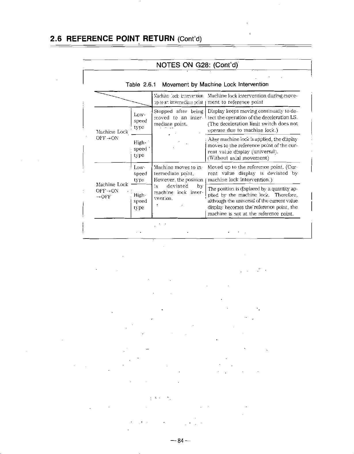
REFERENCE
2.6
POINT
Table
RETURN
NOTES
2.6.1
Movement
(Cont’d)
G28:
ON
by
(Cont’d)
Machine
Lock
Intervention
Machine
-ON
OFF
Machine
OFF
-ON
-OFF
Lock
Lock
Low-
speed
type
High¬
speed
type
Low-
speed
type
High
speed
type
Machine
up
ar.
to
Stopped
rr.oved
mediate
1
Machine
termediate
However,
is
machine
vention.
lock
intervention
mterneciais
after
an
to
point..
moves
point.
position
the
deviated
iock
point
being
inter-
to
in-
by-
inter¬
Machine
roent
|
Display
I
•
the
tect
(The
operate
After
:
moves
rent
(Without
Moved
rent
machine
position
The
plied
although
display
I
machine
lock
intervention
reference
to
keeps
operation
deceleration,
due
to
machine
reference
the
to
display
value
axial
the
to
up
display
value
lock
is
by
the
the
machine
universal
becomes
is
not
point
_
moving
lock
the
of
limit
machine
applied,
is
continually
deceleration
switch
lock.)
point
(universal).
movement)
reference
is
intervention.)
the'
the
by
lock.
of
the
reference
reference
displaced
at
during
does
display
the
the
of
point.
deviated
quantity
a
Therefore,
current
point,
point.
raove-
to
de
LS.
not
cur¬
(Cur
by
ap¬
value
the
—
84
—
Page 97

2.6.2
Reference
This
function
the
reference
returns
to
Point
checks
point
the
reference
Return
whether
after
Check
starting
point.
a
part
from
(G27)
program
the
which
machine
is
created
reference
to
point,
return
correctly
to
G27
1
When
instructed
thenitis
this
However,
ing
and
(1)
Operation
If
that
complete
automatic
position
results,
goes
(2)
G27
If
G27
point
at
a
match.
Tool
X(U)...Z(W)...Z(*C(H)...*Y(V)...)
given,
command
point
checked
check
after
position
lamp
operation
not
is
and
are
is
simultaneously
whether
axes
for
not
that
for
executed.
check
matches
lights.
If
all
is
continued.
matched,
the
automatic
the
machine
for
position
which
the
reference
of
the
restore
operation
axes
two
coordinate
specified
If
position
is
out.)
command
is
instructed
offset
Therefore,
position
by
offset
during
the
G27
cannot
corrected
can
tool
only
cnaceled
be
position
quantity,
be
instructed
|
;
positioned
is
(ÿsimultaneously
the
is
reference
command
point,
axes
there
error
interrupted.
offset,
so
by
G27
reference
the
match
any
is
(alarm
the
that
after
command.
by
rapid
point.
is
omitted,
the
reference
axis
“0421”
cycle
(The
machine
position
the
tool
offset
feed,
for
point
for
which
to
is
positioned
is
the
at
all
axes),
position¬
return
point,
the
“0425”)
lamp
start
not
does
canceled.
E
(3)
Reference
The
machine
automatic
(4)
Mirror
Mirror
avoid
(5)
No
reference
can
image
image
an
unmatch
check
point
point
be
returned
reference
is
validinthe
error,
is
made
means
point
be
if
G27
point
a
by
“manual
return.”
movement
sure
to
is
executed
85-
—
inherent
specify
to
the
reference
direction
in
G27
machine
with
point
by
the
machine
return”
G27
mirror
lock.
which
to
“G28
or
command.
image
off
mode.
the
To
Page 98

REFERENCE
2.6
POINT
RETURN
(Cont’d)
2.6.3
from
.
:
A
—
C
-
Reference
causes
reference
by
going
->
3
C
POINT
B
FG'N”
D
-
RA=IO
PC.N"
Return
function
This
by
automatic
position
nal
Z
X
G2S
5
POINT
X
G2->
li!’lls&sc5'2a
'
INTERMEDIATE
ABD
•Z
D
POINT
FCSriONING
Point
machine,
the
point
return
back
on
-REFERENCE
TRAVERSE
Return
after
(G28
same
the
°OINT;
POSTIONING
\
DO‘
(G29)
\
•
AO
being
G30)
or
path
.
T
-
—
6
:/
/
moved
as
;
REFERENCE
INTERMEDIATE
to
to
returned
be
reference
RETURN
TO
the
reference
point
=0!NT)
REFERENCE
POSTIONING
the
to
return.
PO:NT
POINT
point
origi¬
Advantage
(1)
G29
If
be
used,
being
Movement
(2)
With
axes
coordinate
Fig.
2.6.4
of
instructed,
is
considered
is
G29
useful
returned
from
G29.
movement
up
Jk
(
to
commandisomitted
G29
in
the
to
C
three
Return
from
command
the
distance
program.
returning
in
reference
the
D
to
and
->
C
simultaneously.
axes)
Reference
Especially,
to
from
B
and
Point
Return
betweenBand
if
an
original
the
point.
coordiante
BtoD
is
B->D
executed
However,
do
not
move.
.
not
need
C-
incremental
system
-•
rapid
at
any
axes
'
necessarily
command
after
•
feed
for
for
•
is
once
two
which
—
86
—
Page 99

:
(3)
If
dinate
ultimately
or
G28
G30
value
created
(Example)
;
!
N20
:
N23
!
N24
I
I
G28
G28
G29
Par.
(see
point
of
Indicated
X10.
X30.
X-40.
J
Example
by
B
G29
latest
by
absolute
is
2.6.4)
for
the
Z20.
Z—
50.
G00
I
GOO
i
Programming
of
instructedanumber
movement
G28
becomes
or
G30.
command
!
;
X30.
X-40.
Z20.
Z—
;
50.
Equivalent
[
of
times,
an
intermediate
easy
for
understanding
Intermediate
coordinate
X
,20
10.
(
(
30,-
.20.
;
to
these
two
the
point
value
Z
)
)
blocks
coor¬
point
E
N31
N32
K33
K34
T0300
G28
T0400
G29
;
U80.
;
;
U-80.
:
Fig.
W20.
W40.
2.6.5
;
:
TE
/
/
A
20
B-Point
NOTE
VALUE!
B
K
/
/
Coordinate
Incremental
(move
of
G29
termediate
G91
\
\/
\
40
commands
quantity
point
COMMAND
\
o—
—
Value
for
is
from
not
~x
G29
effective
are
an
intermediate
affected.
!PEcEPENCE
C
Operation
for
the
point)
POINTi
command
and
value
the
in¬
—
87
—
Page 100

REFEREBNCE
2.6
POINT
RETURN
(Cont’d)
NOTES
1
.
G29
If
G29
cycle
command
instructed
is
(G70
results.
on
is
alarm
a
rule,
point
G29
instructed
”0240”
the
B
2.
Note
If
G29
ed.
3.
Noteonissurance
As
is
instructed.
ing
Tool
in
G76,
to
issued
tool
instructed
If
also
is
position
nose
in
nose
G90,
immediately
after
results.
G28,
of
position
offset
offset,
D"
radius
radius
G92,
power
G30,
offset,
while
and
cannot
-
.
./
d'
-V
compensation
compensation
G94,
G81
after
is
turned
or
G29
be
must
the
offset
passes
tool
the
canceled
be
•
.
••
PREFERENCE
AC
T
fj
OFFSET
!
B
NTERVEDiA'E
to
power
on
without
canceled
is
mode
mode
alarm-1
G89),
on
G28
before
applied,
point
B‘
by
G29
POINT;
0JANTiTv
POSTIOMNG
canned
and
(G41,
‘01
or
G30
G28.
intermediate
.
command.
PCN“!
G42)
70”
being
G30,
•
cycle
or
or
position¬
canned
”0182”
execut¬
or
G29
4.
Mismatch
point
In
the
tions
(a)
(b)
(c)
Fig.
2.6.6
between
G29
of
following
the
intermediate
that
cause
When
the
G29
•
•
•
When
celed
When
tion
instructed
is
Setting
Intervention
Intervention
G28,
at
G28,
manual
in
Operation
cases,
point
such
following
of
coordinate
G30,
position
a
G30,
the
intermediate
the
of
G29.
mismatch.
is
machine
of
of
manual
G29
or
different
G29
or
absolute
Tool
when
intermediate
Therefore,
performed
system
(G50,
lock
operation
is
instructed
from
is
instructed
OFF.
Position
point
point
from
.
in
the
of
G28
avoid
the
key
manual
in
a
mirror
after
or
G28
is
G30
or
Offset
of
making
G28
time
setup
operation)
absolute
block
after
image
intervention
Canceled
not
the
and
G30
does
commands
completed
is
OFF
mirror
starting
manual
of
intermediate
match
not
opera¬
or
to
when
is
image
point
can¬
opera¬
—
88
—
 Loading...