


YASNAC
v
CNC SYSTEM FOR MACHINE TOOLS
MAINTENANCE MANUAL
i80
. .
YASUAW14
This manual is primarily intended to give operators maintenance
instructions for YASNAC i80.
The information contained in manual does not provide all
details to be met concerning maintenance and troubleshooting. If
uncertainties be encountered for particular maintenance opera-
tion, refer to following YASNAC i80 documents for additional the
information:
● YASNAC i80 PLC SYSTEM (T OE-C843-11.1)
● YASNAC i80M SPECIFICATIONS (SIE-C843-11.30)
“
YASNAC i80L SPECIFICATIONS (S
“
YASNAC i80M INSTRUCTION MANUAL (T
● YASNAC i80M INSTRUCTION MANUAL APPENDIX
IE-C843-11.20)
OE-C843-11.30)
(TOE-C843-11.31)
“
YASNAC i80L INSTRUCTION MANUAL (T
● YASNAC i80L INSTRUCTION MANUAL APPENDIX
OE-C843-11.20)
(TOE-C843-11.21)
“
YASNAC i80 CONNECTING MANUAL (T
OE-C843-11.5)

I
ROUTINE INSPECTION
. . . . . . . . . . . . . . . . . . . . . . . . . . . . . . . .
57
MAINTENANCE INSTRUMENTS . . . . ...67
TROUBLESHOOTING
. . . . . . . . . . . . . . . . . . . . . . . . . . . . . . . . . . . . . . .
69
ADJUSTMENTS UPON
““””””””””””””””””””””””””””””
135
INSTALLATION
MODULE/UNIT REPLACEMENT
.0,43
PROCEDURE
SETTING AND ADJUSTMENT .00.00.197
OF EACH MODULE
OPERATIONS OF FIXED FILES . ..203
i

CONTENTS
Page
l. OUTLINE
l.l COMPONENTS AND INTERCONNECTIONS . . . . . . . . . . . . . . . . . . . . . . . . . . . . . . . . . . . . 2
1.2 COMPONENTS
2. ROUTINE INSPECTIONSCH EDu LE . . . . . . . . . . . . . . . . . ...000. . . . . . . . . . . . . . . . . . . . . 57
2.1
ROuTINE
2.2 TAPE READER MAINTENANCE . . . .
2.3 CONTROL PANEL . . . . . .
2.4 AC SERVOMOTOR
2.5 BATTERY
MAl NT EN AN
3.
4. TROUBLESHOOTING . . . . . . . . . . . . . . . . . . . . . . . . . . . . . . . . . . . . . . . . . . . . . . . . . . . . . . . . . . 69
4.1’rRouBLE
4.1.1 RECOGNITION OF TROUBLE
4.1.2 RECOGNITION OF NC SYSTEM . . . . . . . . . . . . . . . . . . . . . . . . . . . . . . . . . . . . . . . . . . . ...72
4.2 TROUBLESHOOTING BYALARM
4.2.1 DISPLAY METHOD....•
4.2.1 .1 ALARM INDICATION JOB . . . . . . . . . . . . . . . . . . . . . . . . . . . . . . . . . . . . . . . . . . . . . . . . 79
4.2.2 ALARMS OOIOANDOO1l (PARITY
4.2.3 ALARMS 0016, 0017, 0018, 9016, 9017 AND 9018 (RS-232C ERROR) . “ . . . ...0... 83
4.2.4 ALARM 1099(TEMPERATURE ALARM INSIDE THE PANEL)
”C”””
. . . . . . . . . . . . . . . . . . . . . . . . . . . . . . . . . . . . . . . . . . . . . . . . . . . . . . . . . . . . . . . . . . .
. . . . . . . . . . . . . . . . . . . . . . . . . . . . . . . . . . . . . . . . . . . . . . . . . . . . . . . . . . . . . . . .
Inspection.
. . . . . . . . . . . . . . . . . . . . . . . . . . . . . . . . . . . . . . . . . . . . . . . . . . . . . . . . . . . . 62
“.00 ”O””OO. .c. .oOOoo
CEl
NSTRUME
Identification . . . . . . . . . . . . . . . . . . . . . . . . . . . . . . . . . . . . . . . . . . . . . . . ...71
..C
. . . . . . . . . . . . . . . . . . . . . . . . . . . . . . . . . . . . . . . . . . . . . . . . . ...58
.. O
. . . . . . . . . . . . . . . . . . . . . . . . . . . . . . . . . . . . ...59
. . . . . . . . . . . . . . . . . . . . . . . . . . . . . . . . . . . . . . . . . . . . . . . . . . . . . .
. . .
..o.
coo..o . . . . . . . . . . . . . . . . . . . . . . . . . . . . . . . . . . . 63
NTS... C.........•
STATUS . . . .. O.
CODES S . . . . . . ..00 .0
. . . . . . . . . . . . . . . . .. C . . . . . . . ..
ERROR) . . . . . . . . . . . . . . . . . . . . .. O . . . . . ..O.
. . . . . . . . .. C . . . . . .. C . . . . . . . . . . . . . 67
.COOOO
. . .
..O
. . . . . . . . . . . . . . . . . . . 71
BOO
. . . . . . . . . . . . . . . . . . . . 77
C....•
. . . . . . . . . . . . . . . . . . . 77
. . . . . . . . . . . .
1
11
60
-.82
88
4.2.5 ALARMS,2061 T02068 (ZERO POINT RETURN
4.2.6 ALARMS 2071 T02078,2081T0 2088
(REFERENCE POINT RETURN
4.2.7 ALARMS 2101 T02108(P-SET
4.2.8 ALARM 3000 (SERVO UNREADY) . . . . . . . . . . . . . .
4.2.9 ALARM 3001 (CONTROL NOT
4.2.1 0ALARM3002 (EMERGENCY STOP) . . . . . . . . . . . . . . . . . . . . . . . . . . . . . . . . . . . . . . . . 93
4.2.11 ALARMS 3041 T03048(EXCESSIVE POSITION LAG) . . . . . . . . . . . . . . . . . . . . . . 94
4.2.12 ALARMS 3051 T03054(EXCESSIVE POSITION LAG) . . . . . . . . . . . . . . . . . . . . . . 95
4.2.13 ALARMS 3061 T03068 (MOTOR
4.2.14 ALARMS 3081 T03088(PG DISCONNECTION ERROR) . . . . . . . . . . . . . . . . . . . . 96
4.2.15 ALARMS 3091 TO 3094 (SPINDLE PG DISCONNECTION ERROR)
4.2.16 ALARMS 3121 T03128 (EXCESSIVE
4.2.17,-ALARMS 3141 TO 3148 (PREVENTION OF UNCONTROLLED RUNNING)
4.2.18ALARMS 3161 T03168(ABSOLUTE
4.2.19 ALARMS 3181 T03188 (POSITION
AREA ERROR)......•
ERROR)• . . . ..
READY)
OVERLOAD) S . . . . . . . ..00 . . ..
. . . . .
SPEED) .. O . . . . .. O. C. C . . . . . . . . . . ..
ERRORS) . . . . . . . . . . . . . . . . . . . . .. C.
ERRORS) .. O . . . . . . . . . ..00 . . . . ..
AREA ERROR)
. . .. 00 . . . . . . . ..
O.. 000
. . . . . . . . . . .. O...
..s
. . . . . . . . . . . . . . . . . . . . . . . . . 92
..000 o.c.OOO. .o
. . . . . .
. . . . . ..coo
O.. O......
“.. ”””””89
OO... C
CO.......•
o...
. . . . 96
“ -.. “
. “ 0.. 97
O.....
OOO.
O.. OOO
.
90
91
. ...92
97
“
. 98
. . 98
...99

CONTENTS (Cent’d)
Page
4.2.20 ALARMS 3201 TO 3208 (SERVODRIVE UNIT COMMUNICATION
ERRORS) .. O
4.2.21 ALARMS 3301 T03305 (OVERCURRENT) . . . . . . . . . . . . . . . . . . . . . . . . . . . . . . . ...100
4.2.22 ALARMS 3311 T03315(MCCB TRIP) . . . . . . . . . . . . . . . . . . . . . . . . . . . . . . . . . . . . . .
4.2.23 ALARMS 3321 TO 3325 (REGENERATIVE ERROR) . . . . . . . ..0 . . . . . . . . . . . . . .
4.2.24 ALARMS 3331 T03335 (OVERVOLTAGE) . . . . . . . . . . . . . . . . . . . . . . . . . . . . . . . . . .
. . . . .. O . . . . . .. O . . . . . . . . . . . . . . . . . . . . . . . . . . . . . . . . . . . . . . . . . . . . . . . . ..99
100
100”
101
4.2.25 ALARMS 3341 T03345 (UNDERVOLTAGE) . . . . . . . . . . . . . . . . . . . . . . . . . . . . . . . .
4.2.26 ALARMS 3351 TO 3355 (HEAT SINK OVERHEAT) . . . . . . . . . . . ...-0.... . . . .
4.2.27 ALARMS 3361 TO 3365 (WIRE BREAK IN CURRENT INSTRUCTION
CABLE)"".".• "".
4.2.28 ALARMS 3371 T03375 (MISSING PHASE) . . . . . . . . . . . . . . . . . . . . . . . . . . . . . . . . ..
4.3 TROUBLESHOOTING WITHOUT ALARM
4.3.1
POWER CANNOT RESUPPLIED..
4.3.2 SOLUTION TO ERRORS DETECTED IN SELF-DIAGNOSIS . . ...0....
4.3.2
.lSELF-DIAGNOSIS
4.3.2 .2 DETAILS OF FUNCTION.•
4.3.3 CRT SCREEN DOES NOT DISPLAY . . . . . . . . . . . . . . . . . . . . . . . . . . . . . . . . . . . . . . . .
4.3.4 HANDLE MODE OPERATION
4.3.5 MANuALJOG M0DE0PERATIoN Faulty . . . . . . . . . . . . . . . . . . . . . . . . . . . . . .
4.3.6 MANUAL RAPID MODE
4.3.7 MANUAL ZERO RETURN
4.3.8
CYCLE
START
4.3.9 OPERATION IS NOT AVAILABLE WITH GO1, G02, OR G03 .. 0.0...
4.3.1 OSPINDLE DOES NOT ROTATE . . . . . . . . . . . . . . . . . . . . . . . . . . . . . . . . . . . . . . . . . . . .
4.3.119’’ CRT SCREEN IS DARK . . . . . . . . . . . . . . .. O . . . . . ..
4.3.12 EDIT DOES NOT FUNCTION . . . . . . . . . . ..’ . . . . . . . . . . . . . . . . . . . . . . . . . . . . . . . . . .
4.3.13 FIN WAIT OCCURS BY SPINDLE RELATED INSTRUCTION . . . . . . . . . . “ . . . 125
C.".
O.. 00
. . . . .. C.
FUNCTIONS.. . . . . . . . . . . . . . . . . . . . . . . . . . . . . . . . . . . . . . . . .
. . .. 00 . . . . .
OPERATION
OPERATIoN
FAILURE
.00C ““. ”........
OOO.. 00
..s
FAULTY .. O
. . . . . . . . . . . . . . . . . . . . . . . . . . . . . . . . . . . 102
coDEs
. . . . . . . . . . . . . . . . . . . . . . . . ..$ . . . . . . . . . ...103
..
O
FAULTY......•
FAuLTy . . . . . . . . . . . . . . . . . . . . . . . . . .
. . . . . . . . . . . . . . . . . . . . . . . . . . . .
. . . . . . . . . . . . . . . . . . . . . . . . . . . . . . . . . . 105
. . . . .. O...
. . . . . . . . . . . . . . . . . . . . . . . . . . . . . . . . . .
O.. .00
. .
..OO.
. . . . . . . . . .
. . ..
OO.. O.. C.....• O.. ll7
O..
O . . . . . . . . . . . . . . . . . . . . 123
“ 0... c o c 121
c
0.. c o
..I04
101
101
102
103
104
113
113
115
119
120
1,22
124
(G31)
4.3.14 SKIP FUNCTION
4.3.15 TAPE MODE DOES NOT FUNCTION . . . . . . . . . . . . . . . . . . . . . . . . . . . . . . . . . . . . . .
4.4p0wER suppLyv0LTAGEcHEcK
4.4.1 CHECK AT POWER SUPPLY VOLTAGE . . . . . . . . . . . . . . . . . . . . . . . . . . . . . . . . . ...128
4.4.2 INDICATION OF LAMP OF POWER SUPPLY UNIT . . . . . . . . . . . . . . . . . . . .
4.4.3 CHECK DC POWER SUPPLY VOLTAGE . . . . . . . . . . . . . . . . . . . . . . . . . .
4.5 STATUS DISPLAY BY SELF-DIAGNOSIS FUNCTION (DGN) . . . . . . . . . . . . . . . .
4.5.1 OUTLINE OF DISPLAY . . . . . . . . . . . . . . . . . . . . . . . . . . . . . . . . . . . . . . . . . . . . . . . . . . . .
4.5.2 DISPLAYING INPUT/OUTPUT SIGNALS . . . . . . . . . . . . . . . . . . . . . . ..C. . . . . . . . .
4.
5.
ADJUST ME NTSUPON lNSTALLATl ON
OpERATIoN
Failure . . . . . . . . . . . . . . . . . . . . . . . . . . . .
. . . . . . . . . .
..c
. . . . . . . . . . . . . . . . . . . . . . . . . . .
126
127
128
.... 129
. . . . . . . ...129
130
130
131
. . . . . . . . . . . . . . . . . . . . . . . . . . . . . . . . . . . . . . 135
. . .
111

CONTENTS (Cent’d)
Page
6. MOD ULE/UNIT REPLACEMENT PROCEDURE
6.1
NC RACK””””””””””””””””””””””””””
6.1.1
6.1.2 MODEL JANCD-FCIOOB ”.”.”. . ..”. o... o””” C. COB””””””””””””””””””
6.1.3
6.1.4
6.1.5
6.1.6 MODEL JANCD-FC222/FC224
6.1.7
6.1.8
6.1.9
POWER SUPPLY UNIT (MODEL
MODEL JANCD-FC190-1
MODEL JANCD-FC20000
MODEL JANCD-FC210-1
MODEL JANCD-FC230B .00”.”
MODEL JANCD-FC240 ””
MODEL JANCD-FC300B-3
6.1.10 MODEL
6.1.11 MODEL
6.1.12 MODEL JANCD-FC250-1, 2 (MOTION BOARD)
6.1.13
MODEL JANCD-FC310-1 ”” . . ..
6.1.14 MODEL JANCD-FC400
6.1.15 MODEL JANCD-FC41O
6.1.16 MODEL JANCD-FC420
6.1.17 MODEL JANCD-FC430
6.1.18 MODEL JANCD-FC440
JANCD-FC250
JANCD-FC251
”.””.” “0””
”O”” O0
O”””””
OO”””” “.-. ”.”” ””” O”””” O” C””” as””””-””””””””” “..”””..
CC... CO.
(INTEXB BOARD: STANDARD SPECIFICATIONS) “ “ . “ 162
(INTEXB BOARD: HIGH-SPEED SPECIFICATIONS) “ o 164
"""" """" """"
. . . . . . . . . . . . . . . . . . . . . . . . . . . . . . . . . . . . . . . . . . .
O""" "O"" "" O""" 00"
""""""."""• OO"".
. . . . . . . . . . . . . . . . . . . . . . . . . . . . . . . . . . . . . . . . . . . . . . . . . . . .
““””
”””””””””””””””””””””””””””””””””””” ““ 144
CPS-12N,
””””
00”” ”.OO””” ”O. ”.”- .””. ”.. ”OC” OC ..””””
““”” ”””” ”””” ””””
““”” ”””s
00”” ””..
C.OC CC OOCO””” OO”” OOO” O””” Q”” O”.
”””””””.”-.”.”..”””...””””””
s“””.. .””.O”” ”””””
o””s”””
.
...””””...”””””...”””””””””...”””””””
O""" .".. O."" OOOO""C
.“”o”.
”o”c”””
MODEL CPS-16F) “ “ o “ “ 00 “ “ “ “ . “ o 144
.””” 0””” 00..00 ..”o”” “... ””””.”
”””” 0” ”” ”””” ”””” .””” ””.....” 154
-”. ”””.
. . . .. O"
""" O"
o”c. o.co”
““””
””””.””””..””...””..””””
OO.
"""" o."o""e o-+--
O"" O"" O"" CC"" OO"""""O. O"" CO OOOO
”””” .c0.00”””cooc
””””” ““”””””””-
””.0000”0”””0 “s168
"""
C.o C-"" -"--
“...””””..
““””.”””””
.--oooo 170
.“....”””
oooo-ooo
““”.
143
146
148
150
152
156
158
160
166
172
-
174
176
178
6.1.19 BACK BOARD (MODELS
6.1.20 11-SLOT BACK BOARD (MODEL
6.2 MACHINE CONTROL STATION
6.2.1 9“ AMGC CONTROL PANEL (MODEL
6.2.1 .lMODEL
6.2.1.2MODEL
6.2.1.3MODEL
6.2.1.4 9“ MONOCHROME GRAPHIC CRT UNIT
6.2.1.5 KEYBOARD (MODEL DF8203788)
6.2.2 14” ACGC CONTROL PANEL (MODEL JZNC-IOP1l) ““ ““““ ““““““““ ““ .. ““ ““ ““ 191
6.2.2 .1 MODEL JANCD-FC950-100” O
6.2.2 .2
6.2.2.314” COLOR GRAPHIC CRT UNIT (MODEL
6.2.2.4 KEYBOARD (MODEL
MODEL JANCD-FC951”
JANCD-FC900B”
JANCD-FC901
JANCD-FC903-l
7. SETTING AN DADJUSTM EN TOF EACH MODULE
.-.
8. OPERATl ON SO
8.1
TYPES OF FIXED FILES “ “ o
8.2 DISPLAY
AND WRITING OF FIXED FILES
FFl XEDFl LES"""" OCOOOOO
JANCD-FCOO1, -FCO02, -FC050, -FC052) “ “ “ “ “ “ “ “
“00. ””O. o.coo”.
O”0
““”” ”O”””””
O""""• .""" ."..
.”. ”C”.
O”””. O“O””. o
DF8203921)
””””””0
“000
JANCD-FCO06) ““ .“ ““ .“ ““
”c”oo”o
JZNC-IOPO1) .COO”O”OOOOO”.”””CO”O”OO
””.O.OOOOo ooc”””””oo”” o”” “.””””.”””
""""""""CO""
00””
””””
(MDT948B-3B) c “ “ o “ “ “ “ “ “ “ . . “ “ “ “ “ 189
. . . . . . . . . . . . . . . . . . . . . . . . . . . . . . . . . . . . . . . .
””””
”OOOOO” ””””” 00”” ”’”.
. . ..”oooo
. . . . . . . . . . . . . . . . . . . . . . . . . . . . . . . . . . . . . . . .
o”””
TX1424AD) .0 “ “ “ “ “ o “ o “ s - “ “ ..0.. 194
”o”””.
“0”0””””0”0””0””.”oooooc”.
00”” ”.”OOO” ””””” ”O””. QO” OO””
”oo”. o.” . . .
“““O ““ “.
.””oo”oooo
”...0000O”
..oo” ““””.-”-o.
.“ ““ O. “O 182
““.”””””
““.
““””””””””””””””””””””””””
"O
O""""
. . . . . . . . . . . . . . . . . . . . . . . . . . . . . . . . . . . . . . . . . . . . . . . .
"""" ".
“
".. "O" CC"" "C"" """o "". -""- o-oo
000""00 "Ooo". o-"oo-oo
. . 180
188
””” OO
-
-----
205
184
184
184
187
190
191
193
195
197
’203
204
iv

INDEX
Subject
A
AC SERVOMOTOR
ADJUSTMENTS UPON
Chapter
. . . . . . . . . . . . . . . . . . . . . . . . . . . . . . . . . . . . . . . . . . . . . . . . . . . ...2 . . . . . ...2.4
INSTALLATION
. . . . . . . . . . . . . . . . . . . . . . . . . . . . . .
5
. . . . . . . . . . . . . . . . . . . . ...135
Par
ALARM 1099 (TEMPERATURE ALARM INSIDE THE PANEL) . . . . . . . . 4 . . . . . . . 4.2.4
ALARM
ALARM 3002
ALARM INDICATION JOB . . . . . . . . . . . . . . . . . . . . . . . . . . . . . . . . . . . . . . .
ALARMS OOIOAND 0011
3001(CONTROL NOT
(EMERGENCY
(PARITY ERROR) . . . . . . . . . . . . . . . . . . . . . . . . . . 4 . . . . . . . 4.2.2 . . . . . . . 82
READY ) . . . . . . . . . . . . . . . . . . . . . . . . . . . . . .
STOP)
. . . . . . . . . . . . . . . . . . . . . . . . . . . . . . 4 . . . . . .
l........l.z.g
4
. . . . . . . .
..4.2.1o
4.2.1.1
. . . . . . . . 93
ALARMS 0016, 0017, 0018, 9016, 9017, AND 9018 (RS-232C ERROR) . . 4 . . . . . . . 4.2.3
“ ““ ~~ ““
ALARMS 2061 TO 2068 (ZERO POINT RETURN AREA ERROR) . . . . . . . . 4
4.2.5
ALARMS 2071 TO 2078, 2081 TO 2088
(REFERENCE POINT RETURN AREA ERROR) . . . . . . . 4 . . . . . 4.2.6 . . . . 90
4
ALARMS 2101 T02108(P-SET ERROR) . . . . . . . . . . . . . . . . . . . . . . . . . . . . . . . .
. . . . . ...4.2.7
ALARMs3000 (sERVOUNREADY) . . . . . . . . . . . . . . . . . . . . . . . . . . . . . . . . ...4........4.2.8
ALARMS 3041 TO 3048 (EXCESSIVE POSITION LAG) . . . . . . . . . . . . . . . . 4 . . . . . 4.2.11
ALARMS 3051 TO 3054 (EXCESSIVE POSITION LAG) . . . . . . . . . . . . . . . . 4 . . . . . . . 4.2.12
ALARMS 3061
T03068
(MOTOR
OVERLOAD) . . . . . . . . . . . . . . . . . . . . . . . . . 4 . . . . . . . 4.2.13
ALARMS 3081 TO 3088 (PG DISCONNECTION ERROR) . . . . . . . . . . . . . . . . 4 . . . . . . . . 4.2.14
ALARMS 3091 TO 3094 (SPINDLE PG DISCONNECTION ERROR) . . ~ 4 . . . . . . . . 4.2.15
ALARMS 3121 T03128 (EXCESSIVE SPEED) . . . . . . . . . . . . . . . . . . . . .
ALARMS 3141 TO 3148 (PREVENTION OF UNCONTROLLED
RUNNING)
ALARMs3161 T03168(ABSOLUTE ERRORS)
. . . . . . . . . . . . . . . . . . . . . . . . . . . . . . . . . . . . . . . . . . . . . . . . . . . . . . . . . . . .
. . . . . . . . . . . . . . . . . . . . . .
4........4.2.16
4
.“”””..
..4
. . . . . .
4.2.17
..4. 2.l8
ALARMS 3181 T03188 (POSITION ERRORS) . . . . . . . . . . . . . . . . . . . . . . . . . 4 . . . . . . . . 4.2.19
ALARMS 3201 TO 3208 (SERVODRIVE UNIT COMMUNICATION
ERRORS) . . . . . . . . . . . . . . . . . . . . . . . . . . . . . . . . . . . . . . . . . . . . . . . . . . . . . . . 4 . . . . . .
ALARMs3301
ALARMS 3311 TO 3315
ALARMS 3321
T03305(OVERCURRENT)
(MCCB
TRIP)
. . . . . . . . . . . . . . . . . . . . . . . . .
. . . . . . . . . . . . . . . . . . . . . . . . . . . . . . . . . .
..4
. . . .
4
T03325 (REGENERATIVE ERROR) . . . . . . . . . . . . . . . . . . 4 . . . . . . . . 4.2.23
..4.2.2l
““”.
””.. 4.2.22
..4.2.2o
Page
. . . . . . . . 62
. . . . . . . . 88
. . . . . . . 92
. . . . . . . . 79
.“”” ””””
83
““”’””
““”””””’
““””””””
““..
”...
89
91
92
94
. . . . . . . . 95
““”””.”.
96
. . . 96
““””””””
““”””””.
““”.””
97
97
98
. . . . . . . . 98
. . . . . . . . 99
““””””””
99
. . . . . . . . 100
““””””””loo
““”. ”...1OO
ALARMs3331 T03335(0VERV0LTAGE )
. . . . . . . . . . . . . . . . . . . . . . . . . . . . . 4 . . . . . . . 4.2.24
ALARMs3341 T03345(UNDERV0LTAGE ) . . . . . . . . . . . . . . . . . . . . . . . . . . . 4 . . . . . 4.2.25
ALARMS 3351
T03355(HEAT
SINK
OVERHEAT) . . . . . . . . . . . . . . . ...4 . . . . . . . . 4.2.26
ALARMS 3361 TO 3365 (WIRE BREAK IN CURRENT INSTRUCTION
CABLE )
. . . . . . . . . . . . . . . . . . . . . . . . . . . . . . . . . . . . . . . . . . . . . . . . . . . . . . . . . . . . .
4......4.2.27
ALARMs3371 T03375(M1SSING PHASE) . . . . . . . . . . . . . . . . . . . . . . . . . . . . . 4 . . . . . . . . 4.2.28
B
BACK BOARD (MODELS JANCD-FCOO1,
BATTERY . . . . . . . . . . . . . . . . . . . . . . . . . . . . . . . . . . . . . . . . . . . . . . . . . . . . . . . ..
c
CHECK AT POWER SUPPLY VOLTAGE . . . . . . . . . . . . . . . . . . . . . . . . . . . .
CHECK DC POWER SUPPLY VOLTAGE . . . . . . . . . . . . . . . . . . . . . . . . .
COMPONENTS
COMPONENTS AND
CONTROL
cRTscREEN
cycLE sTARTFAILURE
D
DETAILS OF FUNCTION . . . . . . . . . . . . . . . . . . . . . . . . . . . . . . . . . . . . . . .
DIsPLAY
. . . . . . . . . . . . . . . . . . . . . . . . . . . . . . . . . . . . . . . . . . . . . . . . . . . . 1 . . . . . . . 1.2 . . . . . . . 11
INTERCONNECTIONS . . . . . . . . . . . . . . . . . . . . . . . . . . . . 1 . . . 1.1
PANEL . . . . . . . . . . . . . . . . . . . . . . . . . . . . . . . . . . . . . . . . . . . . . . . 2 . . . . . . . 2.3
DoEs
NoTDIsPLAY
. . . . . . . . . . . . . . . . . . . . . . . . . . . . . . . . . ...4........4.3.3 . . . . . ...113
. . . . . . . . . . . . . . . . . . . . . . . . . . . . . . . . . . . . . . . . ...4........4.3.8 . . . . . ...120
AND WRITING OF
FIXED FILES . . . . . . . . . . . . . . . . . . . . . ...8........8.2 . . . . . ...205
DISPLAY METHOD . . . . . . . . . . . . . . . . . . . . . . . . . . . . . . . . . . . . . . . . . .
-FCO02, -FC050, -FC052)
. . . . 6 . . . . . . . . 6.1.19
2.......2.5
4
. . . . . ...4.4.1 . . . . ...128
4
. . . . . ...4.4.3 . . . . ...129
4
. . . . . .
4
..4.3 .2.2
. . . . . ...4.2.1 . . . . . .
. . . . .
DISPLAYING INPUT/OUTPUT SIGNALS . . . . . . . . . . . . . . . . . ...4.... . ...4.5.2 . . . . ...131
E
EDIT DOES NOT FUNCTION . . . . . . . . . . . . . . . . . . . . . . . . . . . . . . . .
4.......4.3.12
. . . . . ...124
ll-sLOT BACK BOARD(MODEL JANCD-FCO06) . . . . . . . . . . . . . . . . . . . . . . 6 . . . . . . . . 6.1.20 . . . . . . 182
F
FIN WAIT OCCURS
ACG~~ONTROL PANEL (MODEL JZNC-IOP1l) . . . . . . . . . . . . . . . . . . 6 . . . . . . . . 6.2.2
14”
14''COLOR GRAPHIC
H
HANDLE MoDEoPERATIoN
BY
SPINDLE RELATED INSTRUCTION ~~ . . . . . . . 4 . . 4.3.13 . . . . . . . . 125
CRT UNIT (MODE LTX1424AD)
. . . . . . . . . . . . . . . 6 . . . . . . . 6.2.2.3 . . . . ...194
FAuLTY . . . . . . . . . . . . . . . . . . . . . . . . . . . ...4.......4.3.4 . . . . . ...113
. . . . . ...101
. . . . . ...101
. . . . . ...101
. . . . . ...102
. . . . . ...102
. . . . . ...180
. . . . . . . 63
. . . . . . . .
““”””
60
..lo5
. . . . . ...191
2
77
INDICATION OF LAMP OF POWER
I
K
KEYBOARD (MODEL DF8203788)
KEYBOARD (MODEL
DF8203921)
SUPPLY UNIT . . . . . . . . . . . . . . . . . . . 4 . . . . . 4.4.2
. . . . . . . . . . . . . . . . . . . . . . . . . . . 6 . . . . . . . .
. . . . . . . . . . . . . . . . . . . . . . . . . . . . . . . . . . . . 6 . . . . . . . .
. . . . ...129
6.2.1.5........190
6.2.2.4.......195
v
INDEX (Cent’d)
suDject
M
MACHINE CONTROL STATION.. . . . . . . . . . . . . . . . . . . . . . . . . . . . . . . . . . . . ..
MAINTENANCE INSTRUMENTS . . . . . . . . . . . . . . . . . . . . . . . . . . . . . . . . . . . . 3
MANUAL JOG MODE
OPERATION FAULTY . . . . . . . . . . . . . . . . . . . . . . . . . . 4
MANUAL RAPID MODE OPERATION FAULTY . . . . . . . . . . . . . . . . . . . . . 4
MANuALzERo RETuRNoPERATIoN
MODEL JANCD.FCIOOC
MODEL
MODEL
MODEL
MODEL
MODEL
MODEL
MODEL
JANCD.FC190.1 . . . . . . . . . . . . . . . . . . . . . . . . . . . . . . .4 . . . . . . . . . . . . .
JANCD.FC200 . . . . . . . . . . . . . . . . . . . . . . . . . . . . . . . . . . . . . . . . . . . . . . . .
JANCD.FC210.1 . . . . . . . . . . . . . . .. O . . . . . . . . . . . . . . . . . . . . . . . . . . . . .
JANCD.FC222/FC224 . . . . . . . . . . . . . . . . . . . . . . . . . . . . . . . . . . . . . . . . . 6
JANCD.FC230B . . . . . . . . . . . . . . . . . . . . . . . . . . . . . . . . . . . . . . . . . . . . . 6 . . . . . . . 6.1.7
JANCD.FC242 . . . . . . . . . . . . . . . . . . . . . . . . . . . . . . . . . . . . . . . . . . . . . . . .
JANCD-FC250
. . . . . . . . . . . . . . . . . . . . . . . . . . . . . . . . . . . . . . . . . . . . . . . . 6 . . . . . ...6.1.2
(INTEXB BOARD : STANDARD
SPECIFICATIONS) . . . . . . . . . . . . . . . . . . . . . . . . . . . . . . . . . . . . . . . . . . . . . . . ...6 . . . . ...6.1.10
MODEL
MODEL
JANCD-FC250-1,
JANCD-FC251
(INTEXB BOARD : HIGH SPEED
2 (MOTION BOARD)
FAuLTY . . . . . . . . . . .. - . . . . . . ...4 . . . . . . . . 4.3.7
. . . . . . . . . . . . . . . . . . . . . . . .
SPECIFICATIONS) . . . . . . . . . . . . . . . . . . . . . . . . . . . . . . . . . . . . . . . . . . . ...6
MODEL
MODEL
MODEL JANCD-FC400
MODEL
MODEL
MODEL
MODEL JANCD.FC440
MODEL
MODEL JANCD-FC901
MODEL JANCD-FC903-l
JANCD.FC300B.3 . . . . . . . . . . . . . . . . .. O . . . . . . . . . . . . . . . . . . . . . . . . . . . 6
JANCD.FC310.1 . . . . . . . . . . . . . . . . . . . . . . . . . . . . . . . . . . . . . . . . . . . . . . .
. . . . . . . . . .
.."......•
"".. " . .
..". """".
..
"""""6""""""""
JANCD.FC410 . . . . . . . . . . . . . . . . . . . . . . . . . . . . . . . . . . . . . . . . . . . .
JANCD.FC420 . . . . . . . . . . . . . . . . . . . . . . . . . . . . . . . . . . . . . . . . . . . . .
JANCD-FC430 . . . . . . . . . . . . . . . . . . . . . . . . . . . . . . . . . . . . . . . . . . . . . . . . .
. . . . . . . . . . . . . . . . . . . . . . . . . . . .."""
".""
.."" . .."
JANCD.FC900B . . . . . . . . . . . . . . . . . . . . . . . . . . . . . . . . . . . . . . . . . . . . . . . .
. . . . . . . . . . . . . . . . . . . . . . . . . . . . . . . . . . . . . . . . . . .
. . . . . . . . . .
...-"........"."""""""""""""."""
Chapter
6........6.2
. . . . . . . . . . . . . . . . . . . . . . . .
““.””
“...””.
6“”””’”””
..6
. . . . . .
6“””-.””
.”””.”
..6"" """. ""6.l.8
6
.“”””.
““”. ”6 .1.11 ““”””.164
.“o” ...1.9.9
6“””””.
...6"""""""
..< .6""""""
6“””””””” 6.1.17 ““.176
".6..""."".
6“””””
..6
. . . ..6.2
6“””””””
rar. rage
. . . . . ...184
4.3.5
4.3.6
““””””’”
““””””””117
““””””””119
. . . . ...146
6.1.3
..6.l.4
““””
..””
. . . . ...150
6.1.5 ““””””””152
6.1.6
““””””””
““. ””” 156
.“”” ””””
““”. .”.162
6.1.12 ‘.”. ”””166
. . . . . ...160
6.1.13
6.1.14
““168
““170
6.1.15
““””””172
6.1.16
““”””174
6.1.18 ““”178
6.2.1.1
““””184
.1.2” ”””” 187
6.2.1.3
““188
67
115
148
154
158
MODEL JANCD-FC950-l
MODEL JANCD-FC951
MODULE/UNIT REPLACEMENT PROCEDURE”” . . . . . . . . . . . . . . . . . . . . . 6
N
NC RACK
. . . . . . . . . . . . . . . . . . . . . . . .“
9“AMGCCONTROL PANEL
9"
CRT
SCREEN IS DARK
9“MONOCHROME GRAPHIC
o
OPERATION IS NOT AVAILABLE WITH GOI, G02, OR G03 . . . 4 .. ““ ““ “ 4.3.9
OPERATIONS OF
OUTLINE
OUTLINE OF
P
POWER CANNOT BE
. . . . . . . ...”.....”””.””””””
DISPLAY .".
POWER SUPPLY UNIT (MODEL
POWER
R
RECOGNITION OF NC SYSTEM."""."""""""""""""""""""""""""
SUPPLY
RECOGNITION OF TROUBLE STATUS””””””””””””””””””””
ROUTINE INSPECTION”.”.”””””””.”””””””””””””””””””
ROUTINE INSPECTION SCHEDULE..
s
SELF-DIAGNOSIS FUNCTIONS".""""""""""""""".""."""""""""-"
SETTING AND ADJUSTMENT OF EACH MODULE . . . . . . . . . . . . . . . . . . . .
SKIP FUNCTION (G31) OPERATION FAILURE""""""""""""""""""
. . . . . . . . . . . . . . . . . . . . ..
. . . . . . . . . . . . .
..". ".""" "". "". "."" """" """6 """" """6 .2.2. 2"". """""l93
"""""".""
.”””””..”””””””.”””.”””””””””
(MODEL JZNC-IOPO1) ””””””””””””
. . . . ..""
""".
"..
"". "."" """" ". """""""""""""4"".""""
CRT UNIT (MDT948-3B) ””””””
FIXED FILES
"""" """" """" """" """" """"
““”” ”””””””””””””””””””””””
"." "C"""""""""."".""""""""`"""""""""
SUPPLIED .. "" "" "" "" "" "" "" "" "" ""
CPS-12N,
MODEL
VOLTAGE CHECK”””””.”””””””””””””
......””””””.””””””””””””2
6
."8""".
""""" """" ""2o3
4“”.””””” 4.5.1
"""""".""
4“””””””. 4.3.1
CPS-16F) “.. ~~ .“ “
6
. . . . . . . . . . . . . . . . . . . ...143
6“”””””””
6
““””””
““””””
1
6 “ ““ ““ ““ 6.1.1
4
“””.”
4“”””””
4
2 ““””””” 2.1
4
7................197
4“”
SOLUTION TO ERRORS DETECTED IN SELF-DIAGNOSIS ““ “ ““ “ ““ “ 4 .. “. “ “ 4.3.2
SPINDLE DOES NOT ROTATE .
STATUS
T
TAPE MODE DOES NOT FUNCTION
TAPE READER
DISPLAY BY SELF-DIAGNOSIS FuNcTION
MAINTENANCE."".""""".""""""""."""'""."""
TROUBLE IDENTIFICATION.......”””””””””
TROUBLESHOOTING....””””
TROUBLESHOOTING BY
ALARM
TROUBLESHOOTING WITHOUT
TYPES OF FIXED
FILES..............””””””
..”””””””””””””””
(DGN)
.“””””””””””””””””””
““”””””””””””””””””””””
CODES ”””” ”””” ”.”” ”4. ””4.2
ALARM
CODES.”””””””””””””””
4“”’””’””
. . . . . . . . . . 4 . . . . . . . .
4“”.””
2“””””””
4
4:””””””””””””””””””””””””
4
““”””
8“
.“”6 .2.2.1
6.2.1
6.2.1.4
6.1
4.3.11
““””””191
. . . . . ...144
. . . .
..”. 184
..””
.””123
““”””” 189
.-
. . . ...121
. . . . . . . . . . . . . . . . . . . . . . . .
. . . . . . . . 130
. . . . . ...103
. . . . . ...144
4.4
4.1.2
~~~~~~~~ 4.1.1
““”.”””””””””
““”4 .3.2.1
“... .””128
. . . . . . . . 72
.. ”...”” 71
. . . . . . . .
lo4
4.3.14 126
. . . . . . . .
58
57
104
4.3.1o ““””””’”122
4,5
4.3.15
2.2
““”””’”” 4.1
4.3
8.1
. . . . . . . 130
““””127
..”....
.
59
. . . . . . . . 71
69
““””””””
77
. . . . . ...103
. . . . ...204
1
vi

1. OUTLINE
The YASNAC i80 provides you with an internal self-diagnosis function. System maintenance can easily by accomplished with DGN
and other main functions as listed below;
(1)
Microprocessor
nally and can display the status with function keys.
If any failure occurs, NC immediately stops with the blinking
of alarm displays. Also the same precedure can be executed on
machine sequence for the application of built-in type programmable controller.
always monitors the machine operations inter-
ON/OF’F
(2)
displayed with DGN.
Setting value of various parameters such as
(3)
constant and rapid speed can be checked on the CRT,
1. OUTLINE
1.1 COMPONENTS AND INTERCONNECTIONS
1.2 COMPONENTS
SIGNAL of Input to
"..." C"
. . ..
C"""""• """"SO"""""""""""."• "" O". SO""" """." .". "". C.".".""""""• .""""""".".""""• ..". OOOC.. "... "...C.
-"..""• """ O""""• OO"OO."O"OO
NC/Output
CONTENTS
""""" "." C"""" """""""""""""""""C"• """"""""""• """"""""CC
""" O""" C." C"" S" BOO"""""" """""""""""""""• """""""""""O"""""""""""""""".
from NC can be
accel/decel
time
1
2
11
-.
1

1.1
3-PHASE
AC
POWER
SUPPLY
COMPONENTS AND INTERCONNECTIONS
(1) Component Arrangement
+
R—
s—
T—
/
POWER
INPUT
UNIT
ti
L,
?H
OH
&z
*
2*
.:
CONTROL UNIT
u-lb
ok
&a
ZIn
o
v
I
1
GENERAL
PURPOSE
1/0 MODULE
7
L
L
-
AC SERVO
DRIVE UNIT
F
*
AC SERVO
*
DRIVE UNIT
-
AC SERVO
~
DRIVE UNIT
DICITAL
DIGITAL
DIGITAL
lst-AXIS
MOTOR
2nd-AXIS
MOTOR
3~d-AXIS
MOTOR
-J
. . . .
SPINDLE
CONTROL
d
Fig. 1.1 Component Arrangement of YASNACi
CABINET
-
DRIVE
UNIT
SPINDLE
MOTOR
2

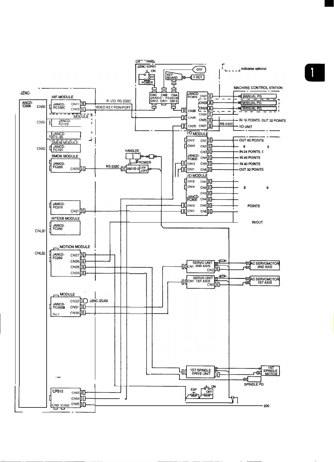
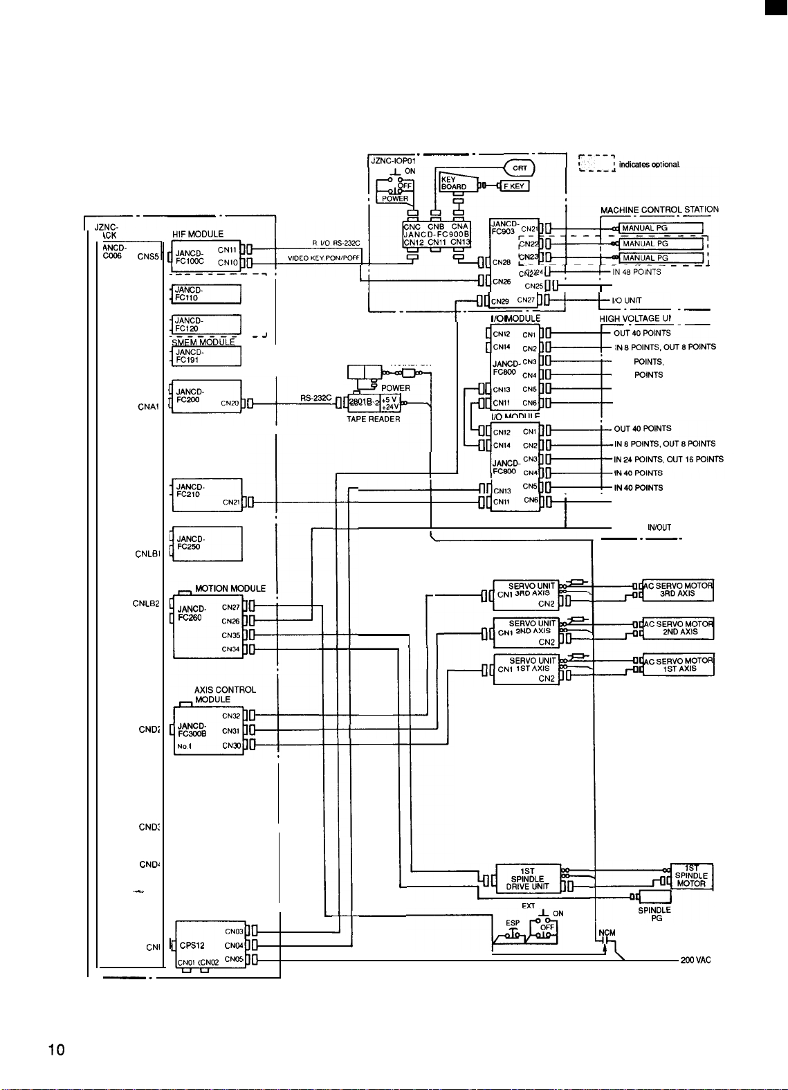
(2) Interconnection Diagram
U MODULE
zNc-l RK22-
ACK BOARD HIF MODULE
‘c””’
‘“s5
1
=~
; ‘co M-u-- M-o
c“” ~-,
‘“s3
i-...j
‘“s2
m
CNA3
CNBI
la
SMEM MODULE
INTEx
MODULE
JANCD-
FC224
b~-i~
CRT PANEL
.—
E“’e
MACHINE CONTROL STATION
—-—
. . . . .
. . . . . . . . . . . . . . . . . . . . . . .
-
?
~
TAPE HANDLER TRANSF~RME
~[
L____
,,,,,.’
POWER
:~
TAPE READER
T
I
+
48 IN POINTS
16 IN, 32 OUT POINTS
1.232C
T
1/0
UNIT
L
.—
HIGH VOLTAGE UNIT
—-
40 OUT POINTS
8 IN, 8 OUT POINTS
24 IN, 16 OUT POINTS
40 IN POINTS
40 IN POINTS
32 OUT POINTS
40 OUT POINTS
8 IN, 8 OUT POINTS
24 IN, 16 OUT POINTS
40 IN POINTS
40 IN POINTS
32 OUT POINTS
I
~
DIRECT
INOUT
-—
.—
SPINDLE
CND3
CONTROL MODULE
JANCD
CND4
FC31O
-’
ko
1
In
CN35 ~
CN34
~
Fig. 1.2
J
IODULE
:-
IZU02
~-
Interconnection Diagram
EXT POWER
L
ESP
[Y AS NAC-i80L
ON
for
SVM
-I(
Lathe]
SPINp\LE
200 vA’
3
1.1 COMPONENTS AND INTERCONNECTIONS (Cent’d)
CPU MODULE
JZNC-l
Rk76
BACK BOARD
r
lANCD-
I
C050
CNG5
CNG4
CNG3
CNG2
CNG1
CNS5
CNS4
CNS3
CNS2
CNA1
APM2 MODULE
m
APM1 MODULE
=
GIF
MODULE
=.
ACP MODULE
m
NIF MODULE
n.
. . . . . . . . . .
COMU MODULE
-:
FILE MODULE
-:
----- . . . . . . . . . . . .
SMEM MODULE
4JANCD-
VIDEO KEY, PON
-F
;
;
r
RS-232C
CRT PANEL
E1@TC~:~;L:TATION
+1
‘POFF
POWER
28016.2
>~
TAPE READER
m
F1.
II
,
—.
ti
+=}LE –-–:
CN12 cN~~+
9
u CN14
‘“zcl~
JANcD-CN3
F c800
CN4
~H~
+ c.,,
+ CN13 CN5
,~~~
CN5
CN1l CN6
l/O
MODULE
CN12 CNI
CN2
‘ 6 IN, 8 OUT POINTS
JAN
CD-CN3
Fc600 CN4
CN6
CN11
MANUAI PG
HIGH VOLTAGE-UNIT
—-—
40
OUT
POINTS
8 IN, 8 OUT POINTS
24 IN, 16 OUT POINTS
40 IN POINTS
40 IN POINTS
32 OUT POINTS
40 OUT POINTS
24 IN, 16 OUT POINTS
40 IN POINTS
40 IN POINTS
32 OUT POINTS
I
OIRECT
IN,
OUT
—.
CNA2
CNA3
CNB1
CNA4
CNB2
CNB3
CND1
CND2
CND3
SPIN DLE
CONTROL MODULE
JANCD-
CND4
FC31O
r~l
a’~
CNP
Fig. 1.3
.~
CN35
Interconnection Diagram [Y AS
I
NAC-i80L
I
~a
SVM
for Lathe with
\
ACGCI
SPINPLE
PG
200 VAC
4
2RT
PANEL
—
-
.—
m
indicates
optional
CPU MODULE
lJZNc-IRK22
BACK BOARD HIF MODULE
‘22:7-’”s;
-
‘m~
f
“co
ti-ti ‘ti-ob”uiE- ?
‘“s4
l~m
I
FILE MO OULE ;
CNS3
I-
. . . . . . . . . . . . . . .
SMEM MODULE
c“”
1-
INTEX3 MODULE
CNA3
JAN CD-
FC224
CNB1
~m
‘z”’
!
~
..J
TAPE
HANDLER
~
L.
POWER
2801
~.’
:2
TAPE READ R
T
~
P
TRANSFORMER
I
I
+0’”” ‘“”JE
+ c.,, CN5
c
+
+
.—
1/0 MODULE
‘: ‘: ~
CN3
JAN CD.
FC800
CN4
CN1l
CN6
Dl+
l/O MODULE
CN12 CN1
CN14 ..2
CN3
JANCD-
Fc600 CN4
c.,, ..5
~]B
c“”
‘“6 b-i-320uT
MACHINE CONTROL STATION
——-—
;-232C
*
16 IN, 32 OUT POINTS
l/O UNIT
L._._
HIGH VOLTAGE UNIT
—- —-—
~:”::::::NTs
24 IN, 16 OUT POINTS
40 IN POINTS
40 IN POINTS
32 OUT POINTS
40 OUT POINTS
8 IN, 8 OUT POINTS
24 IN, 16 OUT POINTS
40 IN POINTS
40 IN POINTS
I
DIRECT
I
‘O’NTs
lN/OUT
.—
.—
.—
MG MODULE
=
~m
AXIS CO
JANCD-
‘ND’
FC3WB
No 1
‘n
SPINDLE
C“D3 cONTROL MODu
JAN CD-
CND4
FC31 O
No 1
In
..-.
Fig. 1.4
NTROI
CN32
‘“31 ~
‘“30
CN35
CNW ~
Interconnection Diagram [Y AS NAC-i80M for Machining Center]
fiODUL
~
&
LE
~
J
~=
S
P
tpNGD
L
ExT
POWER
SVM
i
NCM
•1
J
2
(
E
200 VA’
5

1.1 COMPONENTS AND INTERCONNECTIONS (Cent’d)
CPU MODULE
JZNC-IRK76
BACK BOARD
r–
m
CNG5
CNG4
CNG3
CNG2
CNS5
CNS4
CNS3
CNS1
CNA1
CNA2
pg
m
QIF
MODULE
p,,
. . . . . . . . . . . . . . .
COMU MODULE :
-I
FILE MODULE
-
. . . . . . . . . .
SMEM MODULE
-
SMON MODULE
c.,o~~
-
VIDEO KEY
R 1’0 RS232C
.1
,,
J
‘
CRT PANEL
FC903FC.N::
+
I
I
,
I
?~~.
“
110
MODULE
CN12 CN1
CN14
CN2
JAN CD-
FCBOO
~’E-
~oM;{ti;:;;::;lNTS
JAN CD-
FCBOO
+
CN,, c.,
,~~~
CN1l CN6
CN3
CN4
CN3
c
:
,,
PON/POFF
TRANs Fnn MPn
“DLERm’’”’-’
TAPE READER
___ . -----
N4
m
inciic.tes option.1
MACHINE CONTROL STATION
—- —-—
+..!.?!!!.L-!!
,:,g;,;,,
HIGH V“OLTAGE UNIT
40 OUT POINTS
8 IN, 8 OUT POINTS
24 IN, 16 OUT POINTS
40 IN POINTS
24 IN, 16 OUT POINTS
40 IN POINTS
40 IN POINTS
‘
32 OUT POINTS
DIRECT
1
.—
--
.—
lN/OUT
.—
I
!:
I
CNA3
CNB1
CNA4
CNB2
CNB3
CND1
CND2
CND2
,QND4
CNP
Fig. 1.5
I
—
I
SPIN DLE
CONTROL MODULE
JANCDFC31O
{--1
POWER MODULE
ais
CN35
CN34
No 1
;;:::.
CN03
CN04
NO1 CN02 cNo5
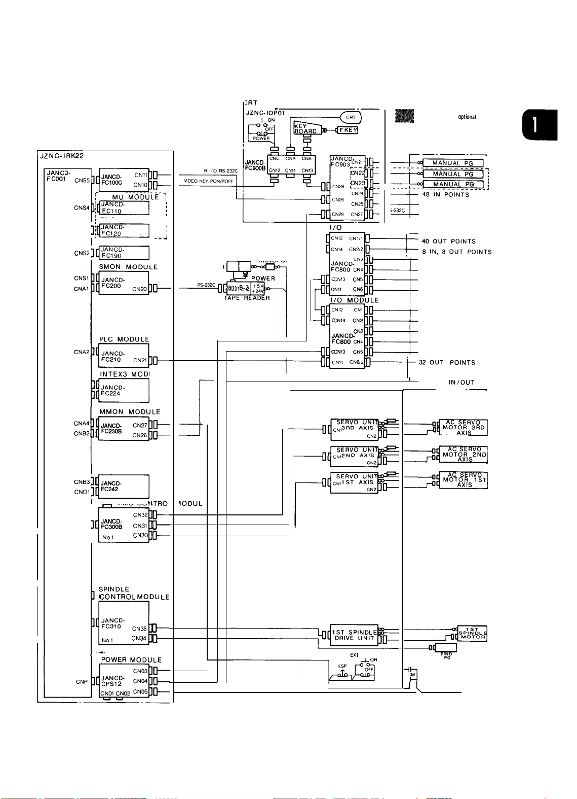
Interconnection Diagram [Y AS NAC-i80M for Machining Center with
I
—
~m
SVM
+
ACM
2
4
SP;NGDLE
ACGC)
6

CRT PANEL
“P,f~
lndlcates
optional
CPU MODULE
‘“s4
CN’,
CNS2
CNB3
CND1
CN02
CND3
CND41SR=
-----
m
(1..!
SMEM MODULE
m
1
l—
mMG
<;;;;.
im
AXIS CONTROL MODULE
JANCD-
FC30f3B
No 1
‘n
AXIS CONTROL MODULE
JANCD-
FC3CQB
NO 2
‘n!
CN32
‘“31
‘NW
CN32
‘“31
CN30
MODULE
:
TAPE HANDLER
~o
~
-
K’p~
~uc””
L
“Y
TRANSFORMER
POWER
‘,,,,.’:;
TAPE READER
3
-
~1
I
0
~
F
““”
CNzsh=
-~+~
1/0
MODULE
::::
JAN
Fc800
+ CN13 CN5
~ CNI1 ..6
nl~
u~u
1/0
CN12
4
m
-n
‘“14
~N13RD
~N1
2ND AX,
a“
7*
CD-CN3
CN4
MOOUL
CN1 ~
‘N’ D
SERVO UN I
AX:,
SERVO UN I
ERVO UNIT
~N1 1S’
AXIS
SERVO UN I
~N1
6TH AXIS
SERVO uNIT
~N1
5TH AX I
SERVO UNIT
~N1
4TH AX I
2ND SPINDLE
DRIVE UNIT
q~-p~.
b
CN2
CN2
CN2
CN2
CN2
b
MACHINE CONTROL STATION
MANUAL PG ]
+
. . . . . ----- ------- ,
48 IN POINTS
16 IN. 32 OUT POINTS
‘N”
HIGH VOLTAGE UNIT
24 IN, 16 OUT POINTS
40 IN POINTS
40 IN POINTS
32 OUT POINTS
40 OUT POINTS
8 IN, 8 OUT POINTS
DIRECT lN /OUT
.— .—
=
MOTOR 2
m
m
=
m
*4
~
.—
ND
2ND
SMP&N7DOL;
SP;:DLE
POWER MODULE
JAN CD- ‘N04
CNP
CPS16
CNOI
Jill
—
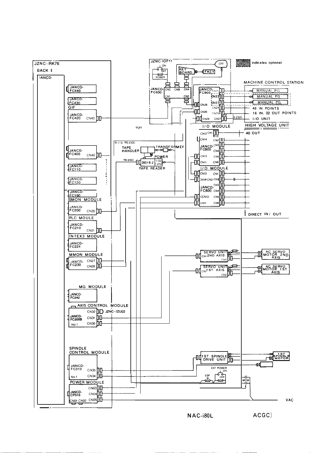
Fig. 1.6
EXT POWER
_L
ESP
ON
,
CN03
‘“02 ‘“05
.—
Interconnection Diagram [Y AS NAC-i80L for Multi-Axis Lathe)
“
NCM
k;
SVM
200 VAC
7

1.1 COMPONENTS AND INTERCONNECTIONS (Cent’d)
.N
PU MODULE
— .
IZNC-IRK58
BACK BOARD
JAN CD-
FC052
c“”
c“” -
1
CNG3
c“’,bm
~~~ =~
CNS4
‘7
APM2 MODULE
m
APM1 MODULE
GIF MODULE
JAN CD.
F C420
/u
ACP MODULE
NIF
~-----
, COMU MODULE
1
CN43
MODULE
-- . . . . . . . . . . .,
-
I
1
~
&
VIDEO, KEY,
C
~g
~
1
CRT PANEL
En-=7
;
PDN/POFF
2,,,,.2 &v
APE READER
‘
T
y$S”*;N
.— .
FC903;!:’
l/O MODULE
-o
.F:::~~:*xT”Ts
c~~:ua::::::
+ c.,, CN2
JAN CD-
,
I
1
[
I
FC800
fl cN13 cN5
!IB
uu~
. . . . . ..__ ----
8 IN, 8 OUT POINTS
CN3
cN4
, 40 IN POINTS
‘i”d’ca’eso”’’”n’
.“!N_u.:L. -pa.....,
HIGH vOLTAGE UNIT
I
I
—
40 OUT POINTS
24 IN, 18 OUT POINTS
40 IN POINTS
32 OUT POINTS
DIRECT lN /OUT
.—
.—
MMON MODULE
CNA4
CN82
Im
Ifi
CNB3
CND1
lb
I I
CND4
~r
CN27
JANCD-
“*WB CN26
JAN CD-
$$;:;-
a~
AXIS CONTROL
N02
NDLE CONTROL MODULE
SPI
-+
~
&
MG MODULE
c“~o+
‘
,MODULE
—
—
----1’--”-
,
------u
—
r
.:1’ !7:
SERVO UNIT
~N1
4TH AXIS
%
-1,
~
.
I ,
!!1s
CN2
CN2
EXT POWER
.
I
m
m
I
-asp’BgLE
vAC
Fig. 1.7
8
Interconnection Diagram [Y AS NAC-i80L for Multi-Axis Lathe with
ACGC]
UK
—-
I
YANEL
fl-
1 ;
- -‘7
,.dicaIe30ui0nal,.”.
CPU MODULE
-—
JZNC-
BACK BOARD
ANCDm
CNS<
r
CNS~
CNS:
CNS
CNS1
CNA1
CNA2
CNA3
CNLBI
CNLB2
CND1
—-
-------
COMU ~DULE , ,
II
;:!::- ]
FILE MODULE
I
t JANCD-
II
Cf-,
., ,-
‘3MEKM-06U~E
m
——-.
1
!-.
I
1
- -
Hi
PLC MODULE
m.
L
1.
:
I
II
‘1
I
l!
TAPE
?AN?LE?
TRANSFORMER
TAPE READER
;2
----
CN’”UI.I
:==;~r:?
I/o
MODULE
-D
CN14
cN2
u
F!-:!+;;’F;;Ts
CN12
b
L
+
—
nmu
CN1
CN14
CN2
CN3
JANCD-
FC800
cN4
CN13 CN5 , IN 40 mlNTS
l-la
,
1
IN 48 POINTS
HIGH VOLTAGE UNIT
~
OUT 40 POINTS
r-—-—
IN 8 POINTS, OUT 8 POINTS
IN 24
WINTS,
OUT 16 POINTS
OUT 40 POINTS
IN 8 POINTS OUT 8 POINTS
IN 24 POINTS OUT 16 POINTS
IN 40 POINTS
OUT 32 POINTS
DIRECT
L. —._
IWOUT
1
—.
CND2
CND?
CND4
CNP
D:’
AXIS CONTROL
..-.
POWER MODULE
CPS12
CM,) CN02 CNK
a:,
CN03
CNM
Fig. 1.8 Interconnection Diagram [Y AS NAC-i80LB for Lathe]
i
EXT POWER
~
AON
NCM
37
\
~
VAC
9
1.1 COMPONENTS AND INTERCONNECTIONS (Cent’d)
CPU MODULE
~-—
\CK
BOARD
-
cNS4
CNS3
CNS2
CNS1
CNAi
CNA2
CNA3
CNLB1
COMU MODULE
n
FILE MODULE
‘sfiE-MfiO-D~L=
m
SMON MODULE
-
B,+
PLC MODULE
m
INTEXB MODULE
CRT PANEL
-
_J
I
I
1
I
I
I
I
=q
~“dcN=
l-_p-~:NL
TAPE
ANDLER
‘
TRANSFORMER
z~,~. ~;~
TAPE READER
%
~dcN13
L
POWER
.—
.
&l
CN24 ~~N48POl~T~
CN25BII
In
MOD~LE HIGH VOLTAGE UNIT
~A&D-
cN3
CN4
CN5
CN13
CN1l
CN6
u!~
1/0
MODULE
E
ms::::fl:uT,.NTs
cN56~IN4DPOINTS
UMD
~“”-~indicateswtio.al.
i
I
0uT32p0’NTs
I
I
~lNTS,
OUT 16 POINTS
~lNTS
lN/OUT
.—.
‘---
-—
—
IN 16 POINTS, OUT 32 POINTS
IN 24
IN 40
IN 40 POINTS
OUT 32 POINTS
DIRECT
—
CNLB2
CND1
CNM
CND:
CND~
.-.
CNI
-
=
MOTION MODULE
JANCD-
FC=
mug
JANCD-
FC-
No
I--*
I
POWER MODULE
I CPS12
CNOt CN02 CNW
a!
CN27
CN26
CN35
CN24
AXIS CONTROL
MODULE
CN32
CN31
CNm
1
CN03
CNW
‘r
I
I
EX7
POWER
NCM
3
L
~\
A9
~ VAC
Fig. 1.9 Interconnection Diagram [Y AS NAC-i80MB for Machining Center]
1.2 COMPONENTS
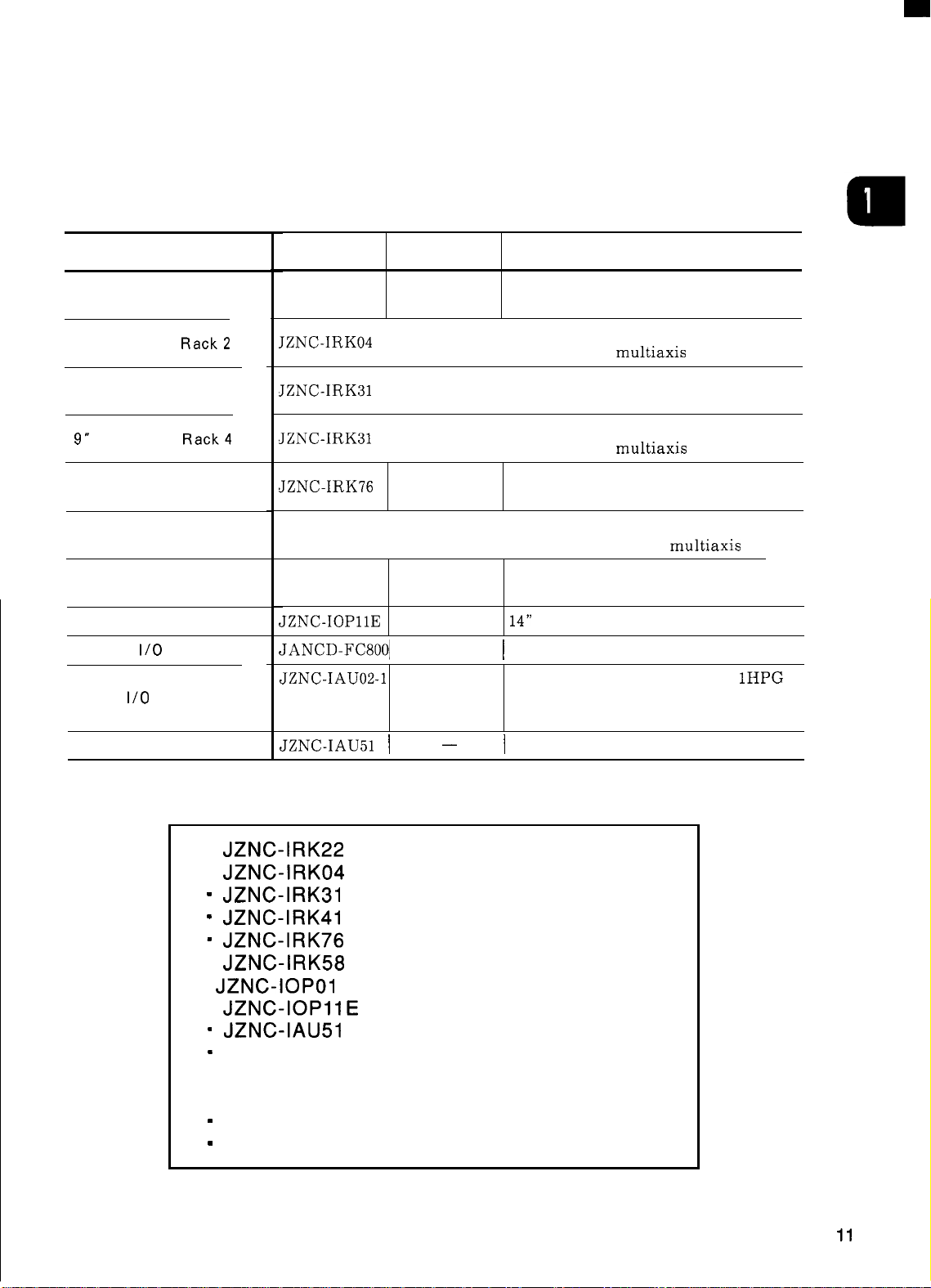
(1) NC Major Components
Component Name
9“ AMGC NC Rack 1
9“ AMGC NC
9“ AMGC NC Rack3
9“ AMGC NC
14” ACGC NC Rack 1
14” ACGC NC Rack 2
9“ AMGC Control Panel
14” ACGC Control Panel
Remote
Panel
Tape Reader Unit
1/0 Unit
Rack2
Rack4
1/0 Module
Table 1.1
Model Supply Code
JZNC-IRK22
JZNC-IRK04
JZNC-IRK31
JZNC-IRK31
JZNC-IRK76
JZNC-IRK58
JZNC-IOPOIE
JZNC-IOP1lE
JANCD-FC8001
JZNC-IAU02-1
JZNC-IAU02-2
JZNC-IAU02-3
JZNC-IAU51 I
NC Major Components
I
I
I
I
DUN20280
DUN2031O
DTN8150
DUN20820
DUN20830
DUN20840
—
—
—
Remarks
Feed control: 3 axes; spindle control: 1
axis; standard rack
Feed control: 6 axes; spindle control: 2
axes; rack for
Feed control: 3 axes; spindle control: 1
axis; standard rack
Feed control: 5 axes; spindle control: 2
axes; rack for
Feed control: 3 axes; spindle control: 1
axis; rack for ACGC
Feed control: 6 axes; spindle control: 2
axes; rack for ACGC
9“ black-and-white CRT. lHPG panel
with 1/0
14”
color CRT, without panel 1/0
I
112-point input, 96-point source output
Separated-type panel 1/0 unit,
Separated-type panel 1/0 unit, 2HPG
Separated-type panel 1/0 unit, 3HPG
I
200VAC input RS-232C tape reader unit
multiaxis
multiaxis
multiaxis
lHPG
■
JZNC-IRK22
■
JZNC-IRK04
“
JZNC-IRK31
“
JZNC-IRK41
= JZNC-IRK76
■
JZNC-IRK58
■ JZNC-IOPO1 E
■
JZNC-IOPIIE
“
JZNC-IAU51
=
Option Modules
● YASNAC i80 digital — Go to (12).
Module —
Module — Go to (3).
Module —
Module —
Module — Go to (6).
Module —
Module — Go to (8).
Module — Go to (9).
Module —
— Go to (11).
Go to (2).
Go to (4).
Go to (5).
Go to (7).
Go to (10).
AC servo drive unit
I
Spindle drive unit
“
Maintenance unit — Go to (14).
— Go to (13).
11
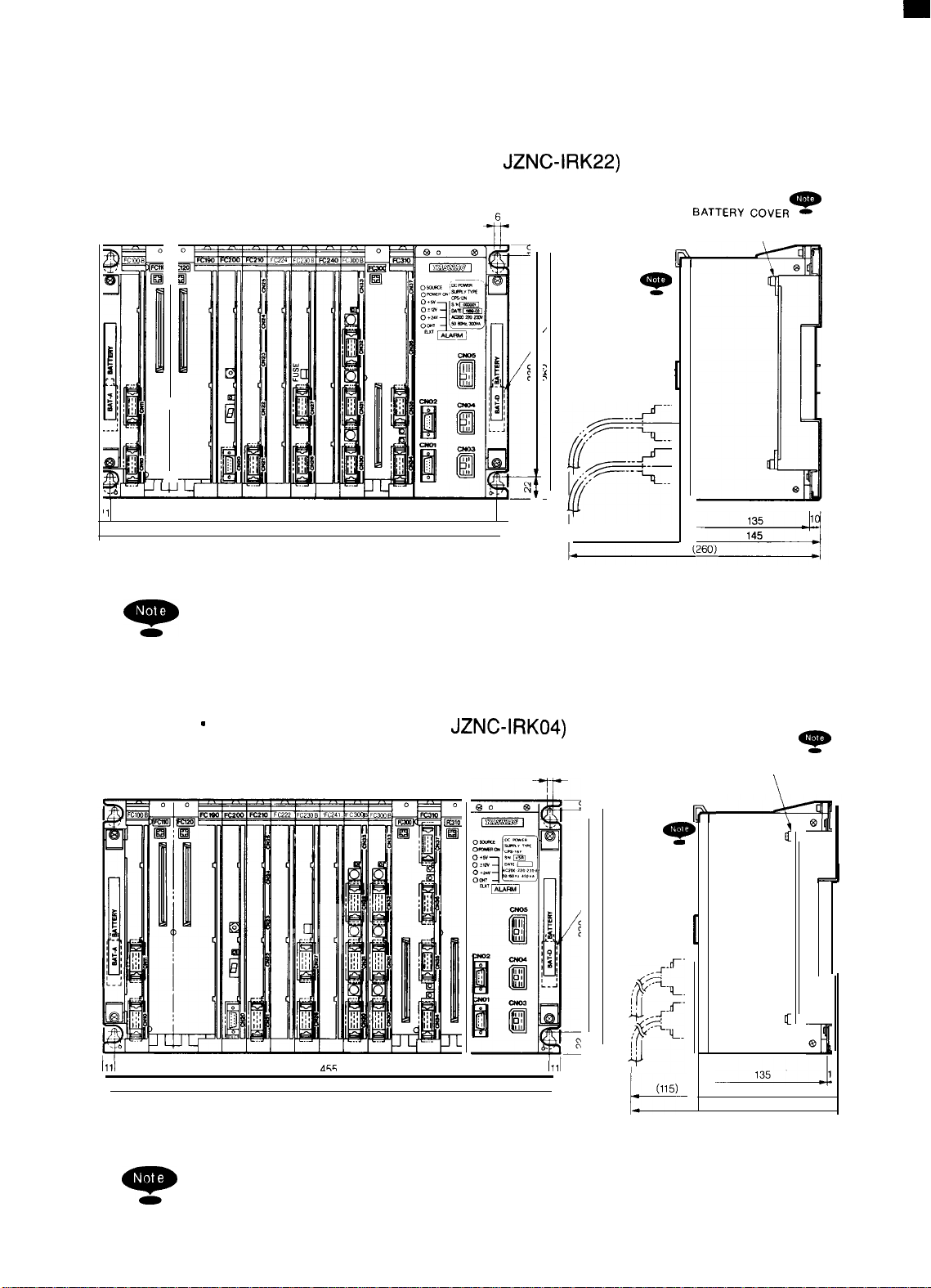
1.2 COMPONENTS (Cent’d)
‘1
● 9“ AMGC Standard Rack (Model
JZNC-IRK22)
~ATTERy
~ovER*
\
*
BATTERY FOR
BACKUP
404
426
9-
q
When replacing the battery for backup, remove the battery cover.
(one at each side)
11
(115)
L
Approx. mass :7.5 kg
II
1111
9
9“
AMGC Multiaxis (Model JZNC-IRK04)
6
q
BATTERY FO
BACKUP
A&c.
1111
(115)
k
a-
q
When replacing the battery for backup, remove the battery cover.
(one at each side)
BATTERY COVER
4
(260)
Approx. mass :8.0 kg
*
\
145
12
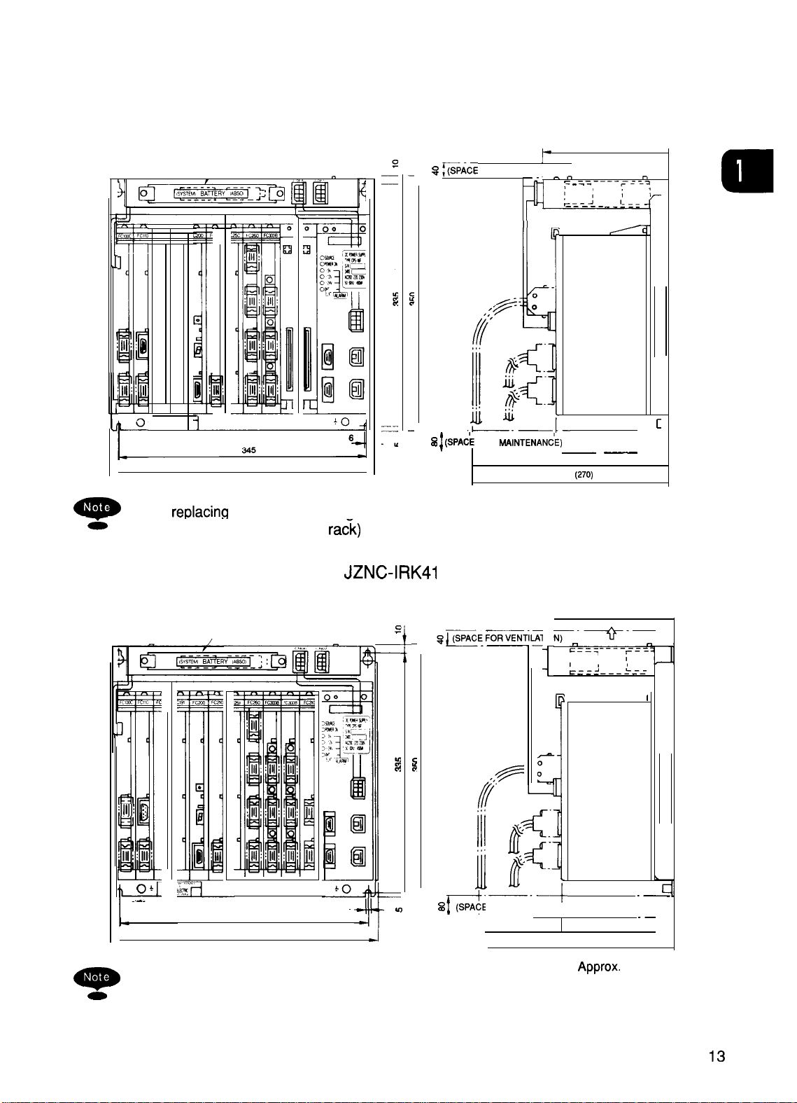
■ 9“ AMGC
BATTERY COVER
Standard
1111
370
When
-
-
(two on the ra&)
replacina
the battery for backup, remove the battery cover.
Rack (Model JZNC-IRK31 )
S SPACE FOR VENTILATION) “‘~”
% ~ (SPA~E
-
FOR WINTENAN;E)
—. — .—
(SPACE FOR CABLES)
(113)
174
P
~
. - = - — --_=_--_=
.-
—--—J-- ._!=.
—
—
“157.3
(270)
Approx. mass :12
_
[
—
,
,
kg
■
9“
AMGC Multiaxis (Model JZNC-IRK41 )
1
:111: j
;111::111’
i
—
0+
. . . .
r
,
_
When replacing the battery for backup, remove the battery cover.
=
(two on the rack)
BATTERY COVER
—
345
370
174
:
●
6
In
J
s
(SPACE FOR MAINTENANCE)
Y“
7-
—-+
.—
(113)
(SPACE FOR CABLES)
~.—~.._
~==i
1 ,
1,,
-----~ ----~--—-
r
(270)
‘Ppr”x”
_------c
:--
157.3
‘ass:’2 ‘g
.
I
o
c
.—
.—
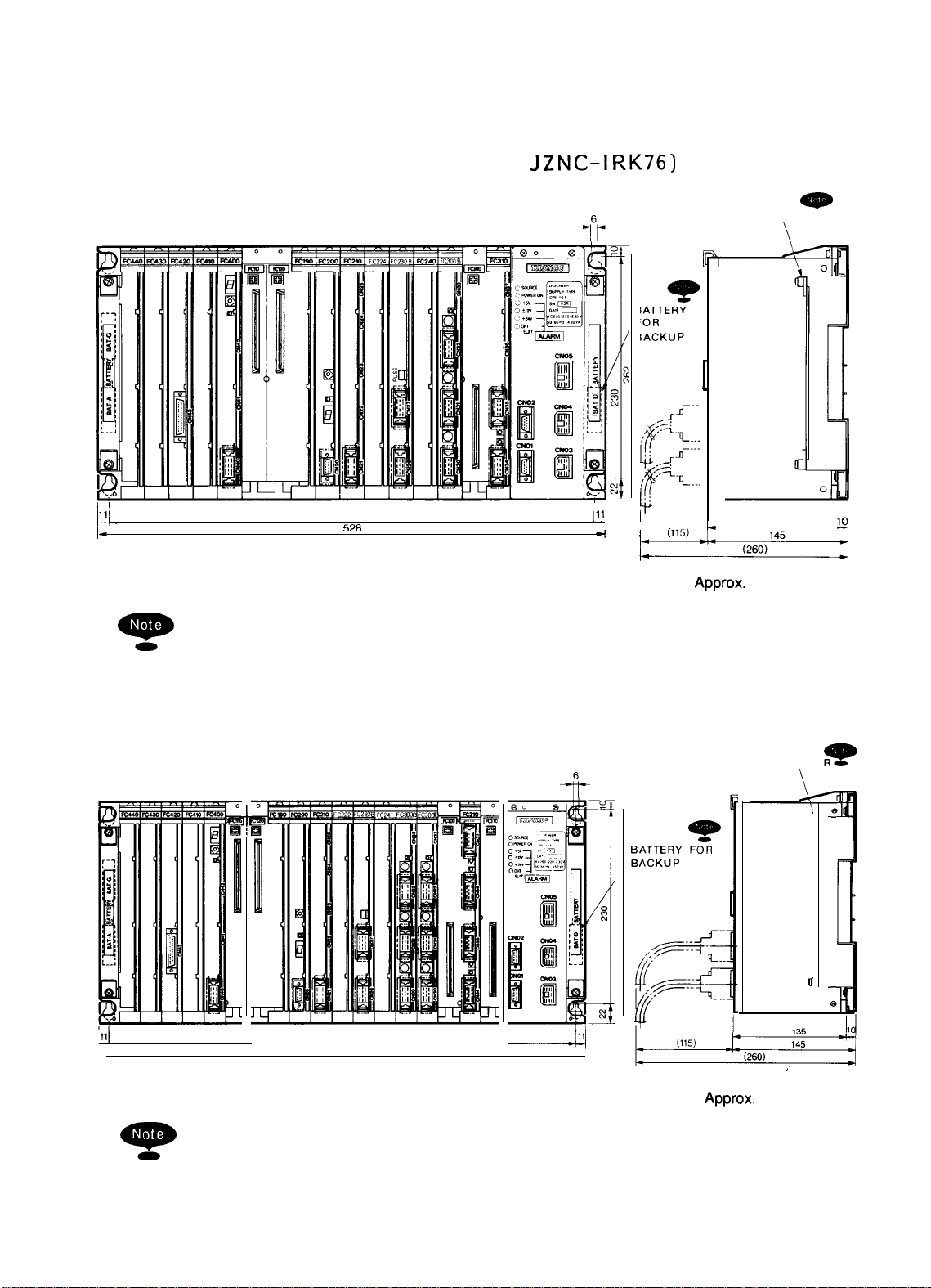
1.2 COMPONENTS (Cent’d)
●
Rack for 14” ACGC (Model
JZNC-IRK76)
BATTERY COVER
-
\
-
Ill
1
,,-
1-
1’
506
69R
---
@-
q
When replacing the battery for backup, remove the battery cover.
(two at the left side and one at the right side)
● Rack for 14” ACGC (Model JZNC-IRK58)
Ill
‘1
I
4
~
k
,.
(115)
.-.
h
1=
Approx.
135
145
mass :9.0 kg
BATTERY COVER
II
1(
9
+
Q
14
u
Ill
Approx.
mass :10 kg
D.
~
When replacing the battery for backup, remove the battery cover.
(two at the left side and one at the right side)

●
_
>
z
w
CtJ
3
m
CN12
(FC9006
4
●
●
II
PA)KING
(ENTIRE CIRCUMFERENCE)
2470 R LESS
REAR VIEW
2
230 OR LESS
i
more.
equiva-
Approx. mass :5.5 kg
u
Japan Painting Institution Color number No. 1034
Japan Etching Co., Ltd. Satin finish No. 7
lent leather-tone painting
1. Panel surface finish:
~
Bot
Connector
material is 8 mm or more
Notch the slash portion with a depth of 8 mm or
2. When the thickness of the operation panel mounting
ml
—
c---
MR-20
CN12
CN21
Number
FC900B
Name
Boerd
JANCD
MR-20
MR-20
MR-50
CN23
CN24
CN22
MR-50
MR-
17SE
CN25
CN26
CN27
FC903
JANCD
PANEL
o
17
CN2817CN29
No cable connector is supplied. User must provide an
equivalent connector.
*
170
170
170
5
—
MOUNTING SIDE
I
—
FRONT VIEW 8-64’
--,
~-
,6
L...-..+d
‘B
n
170 170
170
!
OPERATi~N
TAP
;-M3
Operation Panel Mounting Hole Processing Diagram

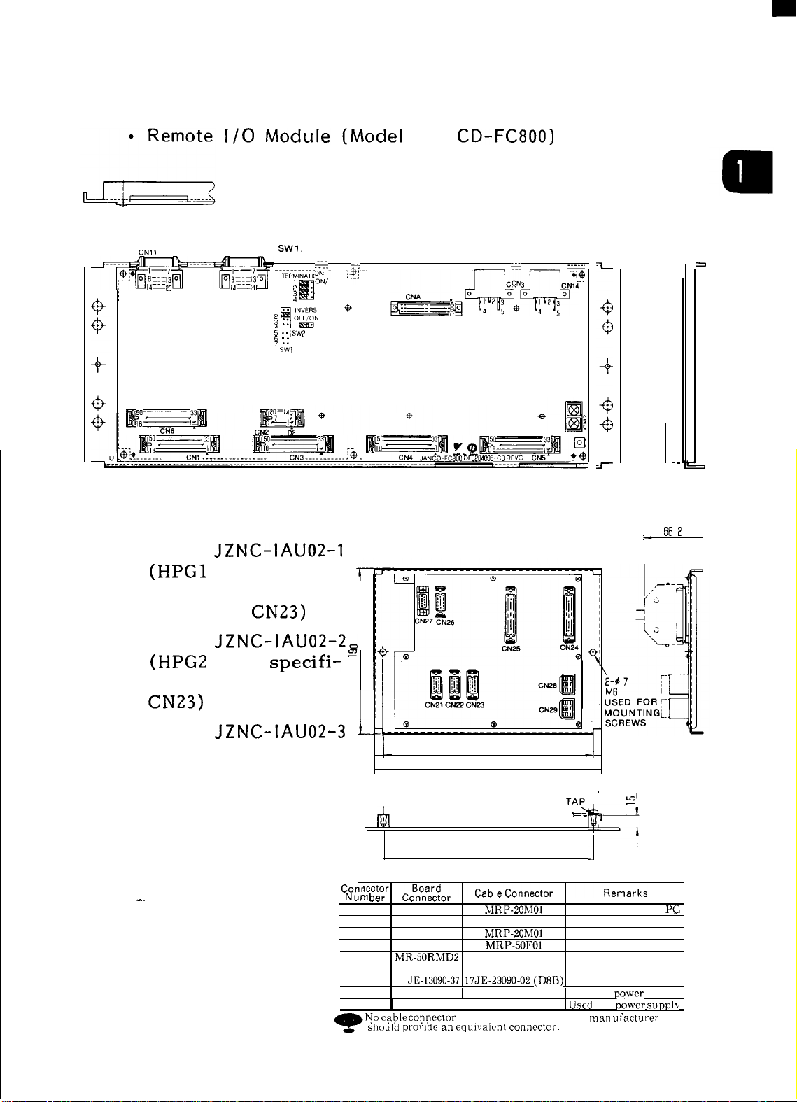
1.2 COMPONENTS (Cent’d)
● 14” ACGC Operation Panel (Model
JZNC-IOP1l
E)
,
v
d
16
—
.
1-
2
0
a
L
—
—
u
CN1l
1/0
CN12
SHORT PLuG FOR
SW1,
SW2, AND SW3
IMSA-9202H–G
..i
. . . . . . . . . . .
.
..icih.ii:ti;--
. . .
. . .
. . ..
JAN
..j
. . . . . . . . . . . . . . . . . . . . . . . . . . . . . . . . . . . . .
..e...
CD-FC800)
..i
. . . . . . . . . . .
. .
..i.4
a
IO-ADDRESS
i~~~”
. . .
5
..swp
y ::
u
SW)
● Panel [/0 Unit
Model
(HPG1
JZNC-IAU02-1
axis specifi-
cations. Without
CN22 and
Model
(HPG2
axis
CN23)
JZNC-IAU02-2=
specifi- =
cations. Without
CN23)
?W
+
‘
*qG--G’
0 45
45
*
.
.
a
6Ei,2
1-
(Not include’
cable height)
I
Model
JZNC-IAU02-3
(HPG3 axis specifi-
cations)
-.
q.
1
L
Mounting Board
Processing Diagram ‘6 ‘AC
—
Conr
Nurr, vcr
CN21
CN22
CN23
CN24
CN25
CN26 M R-20RMD2
CN27
CN28
CN29
~utlile~lur
MR-20RFD2 MRP-20M01 Used for HANDLE
MR-20RFD2
MR-20RFD2
MR-50RMD2 MRP-50F01
MR-50RMD2 MRP-50F01
JE-13090-37
17
172037-1
172037-1
I
I No c~ble
connectnr is supplied, The machine man L] facturer
should
prov]de
240
260
240
MRP-20M01
MRP-20M01
MRP-20F01 Used for remote 1/0
17JE-23090-02 (D8B)
172026-1I Used for
I
172026-1
an cqulvalcnt connector.
-1
#12
t==.
Used for HANDLE PG
Used for HANDLE PG
Used for panel 1/0
Used for panel 1/0
Used for panel RS-232C
I Used
z
f
a+
po~ver
for po,,,cr
supply
suprIlv
PG
17
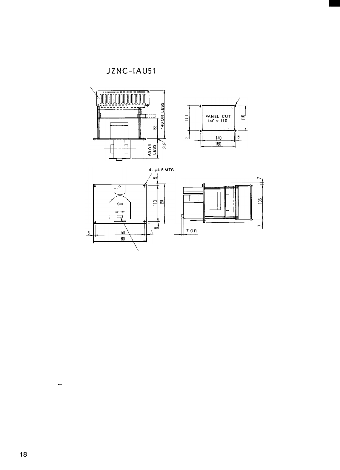
1.2 COMPONENTS (Cent’d)
● Tape Reader Unit (Power Built-in Type)
(Model
POWER TERMINAL
BLOCK
JZNC-IAU51
)
4- M4 TAP
Mounting Hole Processing Diagram
HOLE
r.
-..
\
/
MANUAL FEED
7 OR LESS
-.u--
SWITCH
‘--1
PAINT : SILVER METALLIC PAINT
DIMENSIONS IN
mm
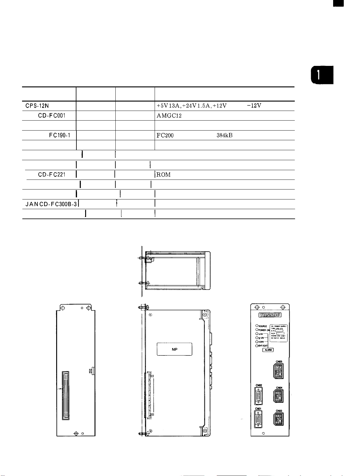
(2) JZNC-IRK22
Module
Table 1.2
Model
CPS-12N
JAN
CD-FCOOI DTN701O
JAN CD-F C1OOC
JAN CD-
JAN CD- FC200 DTN6470
JAN CD-FC21O-1
JAN CD-FC224I DTN9450
JAN
JANCD-FC230B I DTN8490
JAN CD-FC242I DTN1026O I MG
JAN
JANCD-FC31O-1 I DTN6720 I AX2
FC190-1
CD-FC221
CD-
FC300B-31
● Model CPS-12N
Supply Code Abbreviation Remarks
AVR0842
DTN9770
DTN7020
I
DTN6850
I
DTN801O
DTN8570
CPS
BB1
HIF
SMEM
SMON
I
PLC
I
INTEX3 \ NC program analysis
I
ROMS
I
MMON I Motion management
\
AX1
JZNC-IRK22 Module
+5V
13A, +24V
AMGC12 slot back board
9“ monochrome CRT/keyboard interface
FC200
memory RAM
System management
1.5A,
+12V
1.3A, –12V 0.3A
384kB
I Sequence controller, without RS-232C
I ROM
board (two boards for model FC224 are used)
I
Data distribution
I
Feed control: 3 axes
I
Spindle control: 1 axis
II
.
a
:>
.
I
Approx. mass :1.52
kg
19
.
I
--.---------.------ -------
~)----
)-
-----
WI
--_ fi___--n..___
om ~o+amvr
A
-__n__n.
c
___________ ~=.

● Model
JAN
CD-FC190-1
a
Approx. mass :0.32 kg
● Model
CD-FC200
JAN
Approx. mass :0.3 kg
be-----------_____
[_-------_ ---_ -__--.[
21
1.2 COMPONENTS (Cent’d)
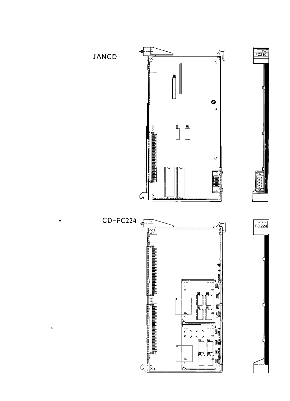
● Sequence Controller
(Model
FC21O-1)
JANCD-
),r-----------------------------------
]
4
.-.
Approx. mass :0.28 kg
Model JAN
(NC program
analysis)
CD-FC224
.
.
‘L
6
-— —...- 2,
----z
L
~@
JL..---.__--!-------_ -._----------! --;
-.--- ——— — — _________
1
m
22
Approx. mass : 0.42kg

● ROM Board (Model --
JANCD-FC221 )
5
(
,,
J
-FC221
● Model
FC230B
Approx.
mass :0.07
JANCD-
kg
+
01
,,
0,
@
Approx. mass :0.28 kg
G
23

1.2 COMPONENTS (Cent’d)
● Model JANCD-FC242
Approx. mass :0.26 kg
.- ———-—
—- —-
.
Y L------------------------------------
<
——.. ——. _—--— —----
/
● Model JANCD-FC300B-
3 (Feed control:
+
3 axes)
1
24
Approx. mass :0.34
@
kg -;

● Model JAN CD- FC31O-1 (Spindle control: 1 axis)
4
.___. .--. _.-_ - . . ..__ —---.
—~q
--. .. —.
-—- ,
FC31 O
R
,x,
a
Approx. mass :0.24 kg
L
25

1.2 COMPONENTS (Cent’d)
(3) JZNC-IRK04
Model
CPS-16F
JAN
CD-FCO02I
JAN CD-F C1OOC
JAN CD-F
JAN CD-FC200
JAN CD-F C21O-1
JAN
JAN
JAN CD-F C230B
JAN CD-FC241
JANCD-FC300B-31 I) TN8570
C190-1
CD-FC222
CD-FC221
JANCD-FC31O-2
Supply Code
AVR843 CPS
DTN8070 I
DTN9770
DTN7020
DTN6470
DTN6850
I
DTN8110 I
DTN801O
DTN8490
DTN8520 MG2
DTN6730
I
Module
Table 1.3
Abbreviation
BB2
HIF
SMEM
SMON
PLC
INTEX2 \ NC program analysis
ROMS
MMON Motion management
I
AX1
AX2
JZNC-IRK04 Module
+5V 21A, +24V 1.5A, +12V 1.3A, –12V 0.3A
I
AMGC,4
slot back
board
9” monochrome CRT/keyboard interface
FC200
memory RAM
System management
Sequence controller, without
ROM board (two boards for model FC222 are used)
Data distribution
I
Feed control: 3 axes
Spindle control: 2 axes
Remarks
384kB
RS-232C
“
Model CPS-16F
4

●
AMGC14
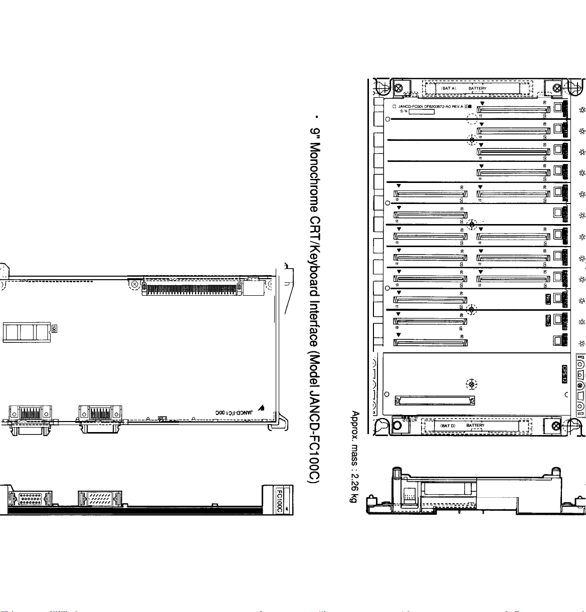
Slot Back Board (Model JAN
w
!9
I
1
CD-FCO02)
Approx. mass :2.26 kg
● JANCD-FC1OOC
●
JANCD-FC190-1
●
I
JANCD-FC200
● JANCD-FC21O-1
* JANCD-FC221
● JANCD-FC230B
●
JANCD-FC300B-3
I
For the models description shown above, see Table 1.2,
and for the model JANCD-FC222, see Table 1.11.
27

1.2
COMPONENTS (Cent’d)
c
Model JAN CD-FC31O-2 (Spindle control:
2 axes)
Approx.
mass :0.2 kg
● Model JAN
CD-FC241
I
FC241
n
2
28
Approx. mass: 0.28
kg

(4)
JZNC-IRK31 Module
Model
CPS-12N
JAN CD-
JAN CD-F C1OOC
JAN CD-
JAN CD-
JAN CD- FC21O-1
JAN CD- FC250
JAN CD-F
JAN CD-F
FCO06
FC191-1 I
FC200
C260-1
C300B-3
■ Model
Table 1.4
I
Supply Code lAbbt-eviation
AVR0842 CPS
DTN1023O
DTN9770
DTN1OO3O I SMEM2 ]
DTN6470
DTN6850
DTN1018O
DTN102OO
DTN8570
BB3 AMGC1l slot back board
HIF
SMON System management
PLC System controller, without RS-232C
INTEXB
MOTION
AX1 Feed control: 3 axes
JZNC-IRK31 Module
JANCD-FCO06
I
+5V 13A, +24V 1.5A, +12V 1.3A, –12V 0.3A
Remarks
9“ monochrome CRT/keyboard interface
FC200
memory RAM
NC program analysis
Motion management, data distribution, spindle
control: 1 axis
384kB
Approx.
mass :4.93 kg
. .
●
JANCD-FC1OOC
“
JANCD-FC300B-3
o
II
&
II
II
------ _________ ______________
@+ o
“
JANCD-FC200
0
II II
For the models description
0
II II II
II
“ JANCD-FC21O-1
shown above,
1
1]
rfiwfiu@
+0
see
Table 1.2.
0
+

1.2 COMPONENTS (Cent’d)
■ Model JANCD-FC191-I _
+-+>
@,r---––-–––––
———— —————— —————- .
1:
II
3
—-————
II
II
II
01
FC191
,E
Approx. mass :0.25 kg
.
Model JANCD-FC250
Onmaaaummm
On
I
H
I
FC250
Approx. mass :0.27 kg
I

“
Model JANCD-FC260-I
Ha
Approx.
mass :0.34 kg
1

1.2 COMPONENTS (Cent’d)
(5) JZNC-IRK41
Type
CPS-12N
JAN CDJAN CD- FC1OOC
JAN CD-F
JAN CD- FC200
JAN CD-F C21O-1
JAN CD- FC250
JAN CD-F
JAN CDJAN CD-F C31O-I
FCO06
C191-1
C260-1
FC300B-:
Supply
code
AVR0842
DTN1023O
DTN9770
DTN1OO3O
DTN6470
DTN6850
DTN1018O
DTN102OO
DTN8570
DTN6730
Module
Table 1.5
~bbreviation
CPS
BB3
HIF
SMEM2
SMON
PLC
INTEXB
MOTION
AX1 Feed control: 3 axes
AX2
JZNC-IRK41 Module
+5V 13A, +24V 1.5A, +12V 1.3A, –12V 0.3A
AMGC1l slot back board
9“ monochrome CRT/keyboard interface
FC200
memory RAM384kB
System management
Sequence controller, without RS-232C
NC program analysis
Motion management, data distribution, spindle
control: 1 axis
Spindle control: 3 axes
Remarks
●
JANCD-FC1OOC
“ JANCD-FC300B-3
“
JANCD-FC200
“ JANCD-FC31O-1
“ JANCD-FC21O-1
For the models description shown above, see Table 1.2.
“ JANCD-FCO06
● JANCD-FC260
“ JANCD-FC191-1
“ JANCD-FC250
For the models description shown above, see Table 1.4.

■ Model JANCD-FC251
Approx.
mass :0.27 kg
+
~,L -----------
~._————_
,1
,;
I
,1
,1
,1
,1
,[
II
II
II
,1
,1
,1
II
,1
,1
II
,1
,1
,1
,1
,1
I
;1
,1
II
II
II
I_\’ _____________
@L__________________-F
___
———-
__T
0
3
q
00 I
00 I
a
~
I
1/
I%t
:
l:’
I’?j
10,
I&l
II
\l
,1
II
,
1.
‘1
1,
,1
//
t;
an
lo!
10
3D:
3Q;
____. )
FC251
B
I
a
I
■ Model
JANCD-FC265
This figure shows
model JANCD-FC265
attached to model
JANCD-FC260.
_
—-— —---—- --- --— ---
.. —---— —- —----- ---
II
II
II
II
11
II II
I ill
FC265
D
!
8
I
I
Approx. mass :0.11
kg
(only JANCD-FC265 board)
33

1.2 COMPONENTS (Cent’d)
(6) JZNC-IRK76
Model
CPS-16F
JAN
CD-FC050
JAN CD-F
JAN CD-FC200
JAN CD- FC21O-1
JAN CD-FC224
JAN CD- FC221
JAN CD-F
JAN CD-FC240
JAN CD-F
JAN CD- FC31O-1
JANCD-FC400
JANCD-FC41O
C190-1
C230B
C300B-3
;upply
Code
AVR843
DTN8030
DTN7020
DTN6470
DTN6850
DTN9450
DTN801O
DTN8490
DTN6530
DTN8570
DTN6720
DTN7090
DTN7080
Module
Table 1.6
Abbreviation Remarks
CPS
ABB1
SMEM
SMON System management
PLC Sequence controller, without
INTEX3 NC program analysis
ROMS ROM board (two boards for model FC224 are used)
MMON Motion management
MG Data distribution
AX1 Feed control: 3 axes
AX2
NIF
ACP
JZNC-IRK76
+5V 21A, +24V 1.5A, +12V 1.3A, –12V 0.3A
ACGC16 slot back board
FC200
Spindle control: 1 axis
ACGC-NC interface module
I
ACGC main module
Module
memory RAM
384kB
RS-232C
JAN
CD-FC221
JANCD-FC420
JAN CD-FC430
JAN CD-FC440
DTN801O
DTN8040
DTN7060
DTN7070
ROMS ROM board (two pieces for FC41O are used)
GIF
APM1 ACGC application memory module
APM2 ACGC application memory module
ACGC graphic control module

:
. . .
rl
~=
2
11-
v
B’
-’;:.’
-“”
$
% r’-’>
JANCD Fc050
[
‘
•1
•1
!
q

1.2 COMPONENTS (Cent’d)
●
ACGC-NC
module (Model
CD-FC400)
JAN
Interface
Approx. mass :0.28 kg
9
ACGC Main
(Model JANCDFC41O)
Modul
e
36
Approx. mass :0.46 kg

● ROM Board (Model
JANCD-FC221 )
~
JANCD-FC22)
●
ACGC
(Model
FC420)
. .
Approx. mass :0.07 kg
Graphic Control Module
JANCD-
4
f
Approx. mass :0.28 kg “-
<
37

1.2 COMPONENTS (Cent’d)
● ACGC Application
Memory Module
(Model
JANCD-FC430)
Approx. mass :0.28 kg
+
~JL
-------------- -
. -----
-------------
ODOI
-; @’l------------------------------------
~
,
e.
● ACGC
Memor
(Model
Application
‘y
Module
JANCD-FC44
38
Approx. mass :0.28 kg

(7) JZNC-IRK58 Module
Table 1.7 JZNC-IRK58 Module
Model
CPS-16F
JANCD-FC052
JAN CDJAN
CD-FC200
JANCD-FC21O-1 I
JAN CD-FC222
JAN CD- FC221
JAN CD-
JAN
CD-FC241
JANCD-FC300B-31 I) TN8570 I AX1
JANCD-FC31O-2
FC230B I
JANCD-FC400
JAN CD-FC41O
JANCD-FC221
I Supply
j
AVR843 j CPS
I
FC190-1 I
I
DTN6470
Code
DTN8030
DTN7020
DTN6850 I
DTN8110
I
DTN801O
I
DTN8490 I MMON
I
DTN8520 I MG
DTN6730 AX2
I
DTN7090
I DTN7080 I
I DTN8010 I
lAbbreviation /
ABB2 ACGC18
I
SMEM]
I
SMON I
PLC
INTEX2
ROMS
NIF ACGC-NC interface module
ACP
ROMS
~OM
Remarks
I
+5V 21A,
FC200 memory
System management
I
Sequence controller, without RS-232C
+24V
1.5A,
slot back board
RAM
+12V
384kB
1.3A, -12V 0.3A
NC program analysis
ROM board (two boards for model FC222 are used)
I
Motion management
I
Data distribution
]
Feed control: 3 axes
Spindle control: 2 axes
I
ACGC main module
board (two pieces for
FC410
are used)
a
JANCD-FC420
JAN CD-FC430
JAN CD- FC440
I
I)TN8040 I GIF
DTN7060
I
DTN7070
I
APM1 ACGC application memory module
APM2 ACGC application memory module
I
ACGC graphic control module

1.2 COMPONENTS (Cent’d)
● Model JAN CD-FC052
ml
.
1
Juul
●
JANCD-FC190-1
●
JANCD-FC200
● JANCD-FC21O-1
●
●
L
JUUUI
JANCD-FC221
JANCD-FC230B
●
JANCD-FC300B-3
For the models description shown above, see Table 1.2.
For the models description shown above, see
●
JANCD-FC400
● JANCD-FC41O
●
JANCD-FC221
●
JANCD-FC420
●
JANCD-FC430
●
JANCD-FC440
Table
1.3.
For the models description shown above, see Table 1.6.

(8) JZNC-IOPOI E Module
Table 1.8 JZNC-IOPOIE Module
Model
JAN CD-
JAN
JAN CD-F
MD T948B-3B
D
E9400035
FC900B-1
CD-FC901
C903-1
● PaneI Interface
Supply Code
DTN8500
DTN6670
DTN8080
CRT16
,
SW825
(Model
Abbreviation Remarks
SP
FKEY
PI02
JANCD-FC900B)
4
Panel interface (for CRT)
Function keyboard
Panel 1/0 lHPG
9“ monochrome graphic CRT unit
Keyboard unit
● Panel
(Model
1/0
JANCD-FC903-1
)
Approx. mass :0.2 kg
,—.4
/—. ,
,— -—.
=4
CN,7
.<7,E !-37
+~
Approx.
“@e’
mass :0.3 kg

1.2 COMPONENTS (Cent’d)
(9)
JZNC-IOPI 1 E Module
Model
JAN CD-F
JAN
TX1424AD
DE8412739
C950-1
CD-FC951 DTN8050
I
SW826
● Panel Interface
(Model
Table 1.9
Supply Code Abbreviation
DTN8190
CRT13
ASP
FKEY Function keyboard
]
JZNC-IOP1l
JANCD-FC950-1
E Module
Remarks
Panel interface
14” monochrome graphic CRT unit
I
Keyboard unit
)
r
42
(1 O)
Model
MO DE L2801 B-2
EYG300/55GTL
MOD
EL1500
MOD
EL1402-1
JZNC-IAU51
Table 1.10
Supply Code
RED18
AVR904
RED14
RED13
Approx. mass :0.18 kg
Module
JZNC-IAU51
Abbreviation
RS-232C
I
I
I
I
Composite power for 5/24V tape reader
I
Option
I
Option
Module
Remarks
tape reader

(11
) Option Modules
Table 1.11 Option Modules
Model
JAN
CD-FCIIO
JAN CD-F
JAN CDJAN CDJAN CD-F
JAN CD-F
JAN CD-F
JAN CD-
JAN CDJAN CD-
JAN CD- FC21O-2
JAN
JAN CD-F
JAN CD-F
C120-I
FC120-2
FC120-3
C120-4
C120-5
C190-2
FC191-2
FC191-3
FC191-4
CD-FC222
C245-1
C245-2
JANCD-FC251
JANCD-FC260-2
JANCD-FC265
upply Code Abbreviation
DTN6450
DTN6370
DTN6760
DTN6770
DTN6980
DTN6990
DTN7030
DTN1OO4O
DTN1OO5O
DTN1OO6O
DTN6500
DTN811O
DTN6820
DTN6590
DTN1018O
DTN1024O
DTN1021O
COM
FILE
FILE Expanded RAM
FILE Expanded RAM
FILE Expanded RAM
FILE
SMEM
SMEM2
SMEM2
SMEM2
PLC
INTEX2 NC program analysis (With extended CPU)
FG
FG
INTEXB2
I
MOTION
I
FG2
Remarks
Communication module
Expanded RAM
Expanded RAM
FC200
memory RAM
FC200
memory RAM
FC200 memory RAM 384kB, with printer I/F
FC200 memory RAM 640kB, with printer I/F
Sequence controller 2 CH RS-232C
Interpolation computing element x
Interpolation computing element x 2
NC program analysis (with high-performance
CPU)
Motion management, data distribution, without
spindle control
Interpolation calculator (for FC 260)
64kB
192kB
448kB
960kB
1984kB
(320 m)
(640 m)
(1280 m)
(2560 m)
(5120 m)
512kB
640kB
I
JANCD-FC301-3
JANCD-FC401
JANCD-FC470
JANCD-FC801
JANCD-FC802
JAN CD-
FC803-3
JANCD-FC900B-:
JAN CD-
FC903-2
JANCD-FC903-3
JAN CDJAN CD-
FC950-2
FC950-3
JAN CD- FC950-4
DTN6660
DTN7050
DTN7040
DTN8160
I)
TN8170
DTN8140
DTN8530
DTN8090 PIo2
DTN81OO
DTN8200
DTN821O
DTN8220
LIF
FDC
I
ARM
I
ADM
DAM Remote 1/0 A/D module
DLB
SP
PI02
ASP
ASP Panel interface, JIS keyboard
ASP Panel interface, video printer, JIS keyboard
Linear scale interface: 3 axes
Floppy disk control
I ACGC debug memory module
] Remote~O
Branch board : 3 axes
Panel interface (for EL)
Panel 1/0 2HPG
Panel 1/0 3HPG
Panel interface, video printer
A/D module
43

1.2 COMPONENTS (Cent’d)
.
Communication Module
(Model
JANCD-FC1l O)
11q-.——— —————— —.-—-——
w
t,
I
,! ,
Ill
1,[
111
1
1
1
1,1
1
1
1
111
111
1
1
1
111
1,1
1,1
Q
I_
I
.
Approx. mass :0.31 kg
.
Expanded RAM
(Model
JANCD-FCI
20)
FC 120
B
u
44
Approx. mass :0.27 kg

.
Sequence Controller
(Model
JANCD-
FC21 O-2)
4
Approx. mass :0.32 kg
.
NC Program Analysis
(Model JANCD-FC222)
~r-----
. . . . . . . . . . . . . . -----------------
~
1!
Approx. mass :0.42 kg
I
1
45

1.2 COMPONENTS (Cent’d)
● Floppy Disk Control
(Model
FC401 )
-
This figure shows
model
attached to model
JANCD-FC400.
JANCD-
JANCD-FC401
Approx.
mass :0.22 kg
+
c
~L___-____________--____
<
,,::=
,,, -.:
(,.+:
-_-__-_---_-@.!
9
ACGC Debug Memory
Module (Model
JAN CD-FC470)
-
-
-
L
L
------------
L
L
.
]0
]
.
D
46
Approx.
mass : 0.35kg
I

● Panel 1/0 (Models JAN
/—. +
/—. ,
/
—-—.
CD-FC903-2
and -3)
..2! w
m., .
-No CN23 for
JANCD-FC903-2,
%.
>1
-1
● Panel Interface (Models JAN
r
:
;
+
● ✎
q
-.
Model
JANCD-FC950-2
has no CNE.
Model
JANCD-FC950-3
has ho CND.
Model
has CND and CNE.
JANCD-FC950-4
;
r
[
“
I
I
CD-FC950-2,
-3, and -4)
—
L
47

1.2 COMPONENTS (Cent’d)
.-.
(12)
Combination of Servopack (SC Type) and Motor
Table 1.12
Motor Model
M Series
F Series
G Series
D Series
R Series USA
Combination of Servopack (SC
USA ME D-03BS
USA ME D-06BS
USA ME D-09BS
USA ME D-12BS
USA ME D-20BS
I
USAF
~
I USAF
I
USAGE
I
USAGE
ED-02CS
ED-20CS
D-02AS
D-03AS
I USA GE D-05AS
USA GE D-09AS
USA GE
USA GE D-20AS
USA GE
B
USA GE D-44AS
D-12AS
D-30AS
USASEM-15AS
USASEM-30AS
USA DE
USA DE D-1OES
t
D-05ES
USA DE D-15ES
USA DE
USA DE
USA
D-22ES
D-37ES
REM-OICS
USA REM-02CS
REM-03CS
USA
REM-05CS
I
USA
REM-07CS
35SC
o
0
0
0 0
0
0
0 0
0
0
0 0
0 0
u
o
0
0 0
SE RVOPACK
10SC
0
I
15SC
0
0
0
0
0
0
\
0
0 0
0
0 0
0
0 0
0 0
Type) and Motor
CACR-IR
20SC 30SC 44SC
I
I ,
010
0 0
0 0
0 0
0 0
0 0
0
0
0
48

(13)
Combination of Servopack (SB Type) and Motor
M Series
F
Series
G Series
S Series
Table 1.13
Motor Model
I USA ME D-06BS
I USA ME
~
USA ME
I USA ME
I USAF ED-05CS
I USAF ED-09CS
-
I USA FE D-30CS
I USA FE D-44CS
I USA GE D-05AS
USA GE
USA GE D-12AS
USA GE
US AGE D-30AS
USA GE D-44AS
USASEM-05AS
E
Combination of Servopack (SB Type) and Motor
D-09BS
05SB
SE RVOPACK CA
10SB
1
15SB
(-)
I I I
n
u
CR-IR
20SB I 30SB I 44SB
o
0
D-30BS
D-44BS
0
0
0
0
0
0
0
D-09AS
0
0
D-20AS
0
0
0
I
0
0
0
0
USASEM-30AS
USA DE
USA DE D-1OES
D Series USA DE
USA DE
USA DE D-37ES
R Series
USA
USA
I
Motor Model
,-”
M Series
F Series
G Series
S Series
D Series
R Series
I
I
I
I
D-05ES
D-15ES
D-22ES
REM-05CS
REM-07CS
Applicable Encoder Type for Motor Models
15-bit Absolute 15-bit New-type
Encoder Incremental Encoder
o
o 0
o 0
o 0
o 0
o
0
0
0
0
Encoder Tv~e
0 0
I
0
17-bit Absolute
Encoder

1.2 COMPONENTS (Cent’d)
● SERVOPACK Model CACR-IR03-20SB
1
MCCB’
HOLE
(2
PWB/
m77M0uNT’NG
0
81
I
-
(145)
\
25
‘\
2!
150
,
PACKING
HEAT SINK
-
NAME PLATE EXTERNAL
SE RVOPACK
Connector Model
CN1
CN2
MR-20RFA
MR-20RMA
I
\\
(TERMINAL SCREW M4)
\
TERM
IN=L
Manufacturer
Honda Communication
Industry Co., Ltd.
Honda Communication
Industry Co., Ltd.
Approx. mass: 5.5kg
~GROUND
TAP
(2-M4)
MOUNTING HOLE ,
CLIPPING
HOLE
4-M6
+
~
100
u
Mounting Hole Processing Diagram
-.
50

● SERVOPACK Model
B-’7:”UT’:H”LE
CACR-IR30SB
“’w’)
PACKING
HEAT SINK
/
I
—
0
NAM
EPLATk
0
\
ixTERNAL TERMINAL
(TERMINAI SCREW M4)
*GROUND
.
G
:
TAP (2-M4)
k
—
—
30)
*
+
n
m
+
SE RVOPACK
Connector Model
CN1
<N2
MR-20RFA
MR-20RMA
Manufacturer
Honda Communication
Industry Co., Ltd.
Honda Communication
Industry Co., Ltd.
Approx. mass: 9kg
4-M
uNT
“
Mounting Hole Processing Diagram
TC:R;GT
N
’
11
Ho
’
% ‘
w
51

1.2 COMPONENTS (Cent’d)
● SERVOPACK Model CACR-IR44SB
BY”””’
‘o”
“’”
PACKING
HEAT SINK
B)
//
—
1 MCCB
.-.
0
0
—
/
—
~
AMEPLATE ExTERNAL TERMINAL
N
\
I
SE RVOPACK
Connector Model
CN1
CN2
MR-20RFA
MR-20RMA
25
‘/
(TERMINAL
~GROUND TAP
\
.
scREW M4)
I
Manufacturer
(2-M4)
Honda Communication
Industry Co., Ltd.
Honda Communication
Industry Co., Ltd.
(2(XI)
MOUNTING HOLE
4-M
&
)0)
+
n~
~ C~O~~G ~ ~
’ u
+
23
100 -
146
Q
+
w
Mounting Hole Processing Diagram
52

m
SERVOPACK Model
CACR-IR [~
1.2 COMPONENTS (Cent’d)
(14)
Spindle Drive Unit
(VS-626MTIII)
Table 1.14 Spindle Drive Units
Drive Unit
CIMR-MTIII-3.7K
CIMR-MTIII-5.5K
CIMR-MTIII-7.5K
CIMR-MTIII-ll
CIMR-MTIII-15K
● Models CIMR-MTIII-3.7K,
-5.5K,
Model
-7.5K
K
Supply Code
—
I
—
—
—
I
—
Spindle Motor
I
i
Specification
Model
UAASKA-04CA1
UAASKA-04CA3
UAASKA-06CA1
UAASKA-06CA3
UAASKA-08CA1
UAASKA-08CA3
UAASKA-llCA1
UAASKA-11CA3
UAASKA-15CA1
UAASKA-15CA3
● Models
-15K
Remarks
Flanged end
Foot-mounted type
Flanged end
Foot-mounted type
Flanged end
Foot-mounted type
Flanged end
Foot-mounted type
Flanged end
Foot-mounted type
CIMR-MTIII-ll
K,
54
-..

(15)
Spindle Drive
Unit
(VS-626VM3)
Drive Unit Model
CIMR-VMS23P7
CIMR-VMS25P5
CIMR-VMS27P5
CIMR-VMS2011
CIMR-VMS2015
CIMR-VMS2018
CIMR-VMS2022
CIMR-VMS2030
Table 1.15
Supply Code
—
—
—
—
—
—
—
—
Spindle Drive Units
Spindle
I
Motor Specification
Model
UAASKA-04CZ1
UAASKA-06CZ3
UAASKA-06CZ1
UAASKA-06CZ3
UAASKA-08CZ1
UAASKA-08CZ3
UAASKA-llCZ1
UAASKA-11CZ3
UAASKA-15CZ1
UAASKA-15CZ3
UAASKA-19CZ1
UAASKA-19CZ3
UAASKA-22CZ1
UAASKA-22CZ3
UAASKJ-30CZ1
Remarks
Flanged end
Foot-mounted type
Flanged end
Foot-mounted type
Flanged end
Foot-mounted type
Flanged end
Foot-mounted type
Flanged end
Foot-mounted type
Flanged end
Foot-mounted type
Flanged end
Foot-mounted
Flanged end
UAASKJ-30CZ3 Foot-mounted type
tvDe
SO OR MORE
A
MAIN CIRCUIT
TERMINAL
MB
9
In-panel Mounted Type
W OR MORE
-’
4-MA
MTG HOLE
‘\
\
DOOR OPENED
\
GROUND
~;RMINAL
MAIN CIRCUIT
, TERMINAL
MB
AIR ~
%7!
J1
9
Heat Sink External Cooling Type
W
OR MORE
~~
60NNEcToR.3 I ~
CONTROL
CIRCUIT
T&RMINAL
5
a
/:
m
A
MAIN
CIRCUIT
~~RMINAL=
. .
-IIIE
SD
OR MORE
[
\
4-MA
MTG HOLE
MAIN
CIRCUIT
TERMINAL
Me
UR
m
w
--,
[
---
AIR
J
55

1.2 COMPONENTS (Cent’d)
(16)
Maintenance Unit
Table 1.16 Maintenance Unit
Model
JZNC-IDU03
—
JZNC-IDU04
JZNC-IDU05
Supply Code Abbreviation
DUN20560
DUN20290
DUN20770
ISD
FDC FDD unit for developing ACGC
AXIM Monitor board for software support
Remarks
Sequence ladder editing unit
56

2. ROUTINE INSPECTION SCHEDULE
This section explains the requirements to be observed for
maintenance time in order to keep the equipment in
optimum operating condition for an extended period.
CONTENTS
2. ROUTINE INSPECTION SCHEDULE".•
".."."......".."".""""..".".................•
. . . . . . . . . . . . . . . . .
57
2.1 ROUTINE INSPECTION
2.2 TAPE READER MAINTENANCE
I
2.3 CONTROL PANEL
2.4
AC SERVOMOTOR CCS". ". O" O"... C"" O"" OOO. O""""..."......"".""""...-".................•
2.5 BATTERY
"-". O""" O" C"""""• "" O"""""""""."".• """"" ."""" -". C...".• "."""".."• "O. O... O........• O....•
O""." ".""" "".""
O." 00
. .
.."..................................•
.OOO
. . ..
. . . . . . .
.."."....".................................•
C..........• 0000
. . . . . . . . . . . . . . . . . . . . . . . . . . . . . . . . .
C................•
. . . .
. . .. O . . . . . . . . .
.. OF
. . . . . . . . . . . . . . . . 60
. . ..
O.. O.. O....
58
.. C... O.O
59
62
. . .. 00 . . ..
O....
63
.-.

2.1 ROUTINE INSPECTION
Table 2.1 shows items that
should be inspected routinely.
Table 2.1 Routine Inspection
58
Section
Tape
Read-
er
Control
Panel
AC
Servo-
motor
Battery
Check Item Frequency
Cleaning of Reading
Head
Cleaning of Tape
Tumble Box
Lubricating of
Tension Arm Shaft End
Doors Tightly Closed
checking
and Gaps in Side Plates
and Worn Door Gaskets
Vibration and Noise Daily
Motor Contamination
and Breakage
for
Loose
As required
As required
As required
Daily
Fit
Monthly
Daily or as
required
At power on
With the
System-off System-on
o
o
o
o
o
o 0
c)
I
Except for those checks which
can be made with the NC in
the energized state, such as
checks for external cleanliness,
vibration, and noise, be sure
to turn off the power supply
to the NC before starting to
undertake routine maintenance
service.
To turn power OFF to the NC
completely, set MCCB (Molded
Case
Circuit Breaker) on the
power panel at the machine to
the OFF position .
-“
e-
~
Turning OFF the power
supply by depressing
the ‘POWER OFF button
on the NC control panel
is not sufficient, be-
cause several areas in
the housing are still
energized, and are potentially dangerous.
~%
With the
Including light source
Feel by hand, and
o
perform an audible
inspection
Visual inspection
Check if alarm for
o
BATTERY is disDlaved
on CRT screen.
Completely
Turned OFF?
Electrical
Power
Suppiy
Remarks
. .
Bg~
YASNAC
i80

2.2 TAPE READER MAINTENANCE
L
1.
@@
TAPE RETAINER
READER HEAD
\
/
(1) Cleaning the Tape
(as required)
Remove tape
(a)
and dust from the glass
with a blower brush. If
the glass is stained with
oil or oily dust, wipe it
using gauze or a soft
cloth with absolute alcohol.
Also clean the tape guide
and the tape retainer.
LIGHT EMITTING
DIODE
TAPE GUIDE
/
Reader Head
contamination
o a~
(b)
(2)
,-.
Remove the dust, if any
on top of LED (light
source) with a blower
brush.
L
lubricating of Tension Arm
c
;haft
(as Required)
E
~or
the control with 6-inch
)r
8-inch diameter reels,
o
1“
ubricate the shaft end of
en
sion arm, when the
t
en sion arm does not move
t
;moothly.
s
-
o
\
/
u\
0
“
When trouble occurs in
-
feeding or winding tape
with 8-inch diameter reels,
open
brush away dust around
the photo-coupler using a
blower brush.
TENSION
Fig.
2.1 8-inch Tape Reel
the
front door and
59

2.3 CONTROL PANEL
This section explains
YASKAWAIS
standard
cabinet. For cabinets customized for customers,
refer to the manual issued by machine
manufacturer.
(1) Checks for Tight Closing
of Doors
The control panal is con-
(a)
(daily)
~
structed as a dust-proof,
sheet-steel enclosure with
n
gasketed doors so as to
keep out dust and oil mists.
Keep each door tightly
closed at all times.
After inspecting the con-
(b)
trol with the door open,
o
7
close the door and fasten
door locks (two per door)
securely using the key
provided (No.
YEOO1)
.
DOOR
~
o
m
~
&
When opening or closing,
insert the key all the way
into the keyhole and turn
until it clicks (approximately
a quarter-turn) .
The key
can be removed from an
open or closed position.
60
OPEN POSITION
CLOSEDPOSTON3
CLOSED
OPEN POSITION
Left - Hand Hinged Door
Movable part “a “
Movable part “a “ is notched vertically. . . . . . .
a.
q
If the optional door interlocking switch is
provided, opening the door shuts off the
main power supply and stops all operations.
t
Fig. 2.2
&.LosEDposToN
Right-Hand Hinged
is notched horizontally, . . . . . .
Door Lock
Door
closed
Opn

(2) Checking for Opening and
Damage
Check gaskets on the rims
(a)
(monthly)
of front and rear doors.
(b) Check if the inside of en-
closure is dusty.
Clean it,
if necessary.
Check for any opening in
(c)
the door base with the doors
shut tightly.
Is the packing damaged?
Dusty ?
Is any opening found?
Constant execution of the
maintenance work described
above will keep YASNAC
i80 in optimum condition
for an extended period.
61

I
2.4
AC
SERVOMOTOR
Vibration and Noise
(1)
or as required)
(daily
-3
Bv hand
a
Vibration can be checked
by resting the hand on the
motor, and for noise, using
a listening stick is
mended.
t y is found,
If any
contact main-
recom-
abnormali-
“i~ra~ion
y
--
(
w
@
tenance personnel immediate-
ly .
62
(2) Motor Contamination and
Damage
(daily or as required)
Check the motor exterior
visually.
If dirt or damage
should be observed, inspect
the motor by removing the
machine cover.
Refer to the
machine manufacturer’s manual.
4.
Checking visually for
contamination and damage

2.5 BATTERY
Checking
Battery
o
Make sure that “BAT” is not
displayed on the lower right
portion of the CRT screen at
power ON.
the battery must be replaced
within a month.
No commercially available
batteries can be used.
When replacing the battery,
be sure to contact your
YASKAWA representative.
<Replacing Procedure>
If it is displayed,
CTOR
YASNAC
r]
x
\
BAT
Depress the POWER OFF
o
@
If a door interlock switch is
provided, turn it
power can be turned
with the door open.
Open the door so that the
NC rack (model:
is visible.
Turn power
Check if the LED on the
model JANCD-FC200, model
FC300B and model JANCD-FC400
boards goes ON.
If the battery must be replaced,
the LED goes ON.
pushbutton.
ON.
OFF. The
ON,
JZNC-IRK [~~[~j[~:
)
JANCD-
63

2.5 BATTERY (Cent’d)
Fig. 2.3, Fig. 2.4 shows the arrangement of LED and
the battery.
Battery for
ACGC memory
a
● ✍
~
/
/
Fig. 2.3
,-.
,(
I
,
,
+
r
1
,
,
,-,
L-1
~
Fig. 2.4 I
Arrangement of LED and Battery
(9” AMGC NC Rack 1)
,
‘
>
I
.
I
-
‘
~
-
J
.
‘
~.,
!
. . .
3attery Layout (14” ACGC NC Rack 1)
, ,
,
!
Three types of batteries are available:
memory, for absolute encoder and for
ACGC
for NC
memory.
64

Battery for
NC memory
a
II
II
,
r<
F
m.
-,
Fig. 2.5
● 000 The procedure for checking a defective
battery is completed at this point.
Battery
model:
Battery Layout (9” AMGC NC Rack 3)
ER6V3 Supply code BA507
Bettery
~
LED for absolute
encoder
elerm
D
❑
Turn the power OFF.
the screws and remove the battery cover.
the battery mounted in the holder.
❑
Put the new battery in the holder and set the
connector.
matter.
See Fig. 2.6.
The direction of the connector does not
Poor connection will not cause conduction.
CORRECT CORRECT
Fig. 2.6
Use a screwdriver to remove
Remove
WRONG
Battery Connection
65

2.5 BATTERY (Cent’d)
❑
With the power ON, make sure that the blinking
display on the CRT screen or the red LED at the
front of the model
and model JANCD-FC400 boards goes OFF.
JANCD-FC200,
model
JANCD-FC300B
-a
If they are still illuminated, it is due to an
improper battery connection or a defective battery.
@
When any of alarms 2121 and after (encoder battery
error) occurs, DGN
When DGN
only in the case where the CMOS backup battery is
exhausted.
This battery differs from the encoder battery.
//35024 ($’BALM)
//35024 ($’BALM)
is output, the LED goes on
is not output.
66

3. MAINTENANCE INSTRUMENTS
This section describes maintenance instruments.
CONTENTS
3. MAINTENANCE
..*, .,.!.
. .
..!, -...
. .
., --.
lNSTRUM EN TS
. . . . ..
000
. . . . . ..
OCCOOO
. . . . . . . . . . . . . . . . . . . .. O......• . . . . . . . . . . . . . . . . . .
67
..-.

3. MAINTENANCE INSTRUMENTS (Cent’d)
(1) Measuring Instruments
Name
Tester or
Multi-Purpose
Digital Meter
(2)
(3)
Table 3.1
Allowable Measuring Range
10 to 300 VAC
(at 40 to 100 Hz)
Tolerance:
Several
Tolerance:
Up to multiples of 10
Tolerance:
Measuring Instruments
*2%
mV
to 100 VDC
+2%
MQ
+5%
Purpose
To measure AC power
voltages
To measure DC power
voltages
To measure currents,
etc.
Tools
Phillips screwdrivers:
large, medium, and smal 1
Standard screwdrivers:
medium and small
ROM extractor: IC EXTRACTOR
model GX-6
Chemicals
TESTER
MULTI-PURPOSE
DIGITAL METER
@
PHILLIPS SCREWDRIVER
@
STANDARD SCREWDRIVER
Cleaning agent for tape
reader (absolute alcohol)
Maintenance
(4)
Fuse model:
parts
HM03 0.3 A
Approx. mass: 0.4 g
?h3-
~.
&
68

4. TROUBLESHOOTING
This section describes troubleshooting by alarm codes,
troubleshooting
checks,
and status display by the on-line diagnostics
function.
The contents of this section should be understood fully to
minimize the down time of your system due to malfunctions.
4. TROUBLESHOOTING . . . . .. 00 . . .. O.....•
4.1
TROUBLE
4.1.1 RECOGNITION OF TROUBLE STATUS
IDENTIFICATION . . . . . . . . . . . . . . . . . . . . . . . . . . . . . . . . . . . . . . . . . . . . . . . . . . . . . . . . . . . . . . . . . . . . . . . . . . . 7]
without alarm codes,
CONTENTS
.O..C... 000
. . . ..
O....................•
. . . . . . . . . . . . . . . . . . . . . . . . . . . . . . . . . . . . . . . . . . . . . . . . . . . . . . . . .
supply voltage
. . .. 00 . . .. O . . . . . . . . . . . . . . . . . . . 69
A
a
71
4.1.2 RECOGNITION OF NC SYSTEM . . . . . . . .
4.2
TROUBLESHOOTING BY ALARM CODES . ..
4.2.1
DISPLAY METHOD• . . . . . . . . .. O.
4.2.2
ALARMS 0010 AND 0011 (PARITY
4.2.3
ALARMS 0016, 0017, 0018, 9016, 9017 AND 9018 (RS-232C ERROR) . . . . . . . . . . . . . . . . . . 83
ALARM 1099 (TEMPERATURE ALARM INSIDE THE PANEL) . . . . . . . . . . . . . . . . . . 88
4.2.4
4.2.5
ALARMS 2061 TO 2068 (ZERO POINT RETURN AREA ERROR) . . . . . . . . . . . . . . . . . . 89
4.2.6
ALARMS 2071 TO 2078, 2081 TO 2088
(REFERENCE POINT RETURN AREA
4.2.7
ALARMS 2101 TO 2108 (P-SET ERROR)
4.2.8
ALARM 3000 (SERVO UNREADY) . .. 00 . . . . . . . . . . . . . . ..
ALARM 3001 (CONTROL NOT READY) . . . . . . . . . . . . . . . . . . . . . . . . . . . . . . . . . . . . .
4.2.9
4.2.10 ALARM 3002 (EMERGENCY STOP)
4.2.11 ALARMS 3041 TO 3048 (EXCESSIVE POSITION LAG) . . . . . . . . . . . . . . . . . . . . . . . . . . . . . . . . . 94
4.2.12 ALARMS 3051 TO 3054 (EXCESSIVE POSITION LAG) . . . . . . . . . . . . . . . . . . . . . . . . . . . . . . . . . 95
4.2.13 ALARMS 3061 TO 3068 (MOTOR OVERLOAD)
4.2.14 ALARMS 3081 TO 3088 (PG DISCONNECTION ERROR) . . . . . . . . . . . . . . . . . . . . . . . . . . . . . . 96
.-.
000
. . . . . . ..
ERROR)
.. O. O.......• O....• O...........• O
S.........•
O.. CO
. . . . . . ..
. . . . . . . . . . . . . . . . . . . . . . . . . . . . . . . . . . . . . . . . . . . . . . . . 82
ERR()R)
. . . . . . ..
CC.. C. C... O
. . . . . . . . . . . . . . . . . . . . . . . . . . . . . . . . . . . . . . . 77
. . . . . . . . . . . . . . . . . . . . . . . . . . . . . . . . . . . . . . . . . .
. . . . . . . . . . . . . . . . . . . . . . . . . . . . . . . . . . . . . . . . . . . . . . . . . . . . . . . . .
O.. O...........• O
. . . . . . . . . . . . . . . . . . . . . . . . . . . . . . . . . . . . . . . . . . . . . . . . . . . . . . . . . . . .
. . . . . . . . . . . . . . . . . . . . . . . . . 72
O.. O
. . . . . ..
. . . . . . . . . . . . . . . . . . . . . . . . . . . . . . . . . . . . . . . . . . . . .
C.. CO
. . . . . . . . . . . . . . . . 77
go
91
. . . . . . . . . . . . . . . . . . . . . . . . . 92
.. O
. . . . . . . . . . . . . . 92
93
96
4.2.15 ALARMS 3091 TO 3094 (SPINDLE PG DISCONNECTION ERROR)
4.2.16
ALARMS 3121 TO 3128 (EXCESSIVE SPEED) . . . . . . . . . . . . . . . . . . . . . . . . . . . . . . . . . . . . . . . . . . . . . 97
4.2.17 ALARMS 3141 TO 3148 (PREVENTION OF UNCONTROLLED RUNNING)
.o.-”ooo.......
““.
97
98
69

4.2.18
4.2.19
4.2.20
4.2.21
4.2.22
4.2.23
4.2.24
4.2.25
4.2.26
4.2.27
4.2.28
-- .,-,--.,- ,.
LUINlklNIS
ALARMS 3161 TO 3168 (ABSOLUTE
ALARMS 3181
ALARMS 3201 TO 3208 (SERVODRIVE UNIT
COMMUNICATION ERRORS) ..
ALARMS 3301 TO 3305 (OVERCURRENT) . . . . . . . . . . . . . . . . . . . . . . . . . . . . . . . . . . . . . . . . . . . . . . . .
ALARMS 3311 TO 3315 (MCCB
ALARMS 3321 TO 3325 (REGENERATIVE ERROR) . . . . . . . . . . . . . . . . . . . . . . . . . . . . . . . . .
ALARNIS 3331 TO 3335 (OVERVOLTAGE)
ALARMS 3341 TO 3345 (UNDERVOLTAGE) . . . . . . . . . . . . . . . . . . . . . . . . . . . . . . . . . . . . . . . . . . . . .
ALARMS 3351 TO 3355 (HEAT SINK OVERHEAT) . . . . . . . . . . . . . . . . . . . . . . . . . . . . . . . . . . . .
ALARMS 3361 TO 3365 (WIRE BREAK IN CURRENT
INSTRUCTION CABLE) . . . . . . .
ALARMS 3371 TO 3375 (MISSING PHASE)
TO 3188 (POSITION ERRORS) . . . . . . . . . . . . . . . . . . . . . . . . . . . . . . . . . . . . . . . . . . . . . 99
ERRORS)• 00
CCO
. . . ..
TRIP)
.. O.. O........• OCOOCOO.
. . . . . . .
O... O........• .O. O
. . . . . . . . . . . . . . . . . . . . . . ..
. . . .. C . . . . . . . . . . . . . . . . . . . . . . . . . . . . . . . . . . . 99
""""" """""""""""""""""""""""""""""""""'""""""""""""
O . . . ..
.. C.................•
C........• O
. . . . . . . . . . . . . . . . . . . . . . . . . . . . . . . . . . . . . . . . . . . . . . . .
. . . . . . . . . . . . . . . . . . . . . . . . . . . .
. . . . . . . .
C.. 00
. . . . . . . . . ..
CC. C... O. O....... 100
..O...
98
100
100
101
Iol
lol
102
102
4.3 TROUBLESHOOTING WITHOUT ALARM CODES
4.3.1 POWER CANNOT BE SUPPLIED
4.3.2 SOLUTION TO ERRORS DETECTED IN SELF–DIAGNOSIS
4.3.3 CRT SCREEN DOES NOT
4.3.4 HANDLE MODE OPERATION
4.3.5 MANUAL JOG MODE OPERATION
4.3.6 MANUAL RAPID MODE OPERATION FAULTY . . . . . . . . . . . . . . . . . . . . . . . . . . . . . . . . . . . . . . .
4.3.7 MANUAL ZERO RETURN OPERATION
4.3.8 CYCLE START FAILURE . . . . . . . . . . . . . . . . . . .
4.3.9 OPERATION IS NOT AVAILABLE WITH
4.3.10 SPINDLE DOES NOT ROTATE . . . . . ..
4.3.11 9“ CRT SCREEN IS DARK
4.3.12 EDIT DOES NOT FUNCTION
4.3.13 FIN WAIT OCCURS BY SPINDLE RELATED INSTRUCTION . . . . . . . . . . . . . . . . . .
4.3.14 SKIP FUNCTION (G31) OPERATION FAILURE
4.3.15 TAPE MODE DOES NOT FUNCTION
4.4 POWER SUPPLY VOLTAGE CHECK
4.4.1 CHECK AT POWER SUPPLY VOLTAGE . . . . . . . ..
4.4.2 INDICATION OF LAMP OF POWER SUPPLY UNIT . . . . . . . . . .. O . . . . . . . . . . . . . . . ..
4.4.3 CHECK DC POWER SUPPLY VOLTAGE . . . . . . . . . .
.-.
4.5 STATUS DISPLAY BY SELF-DIAGNOSIS FUNCTION
4.5.1 OUTLINE OF DISPLAY
4.5.2 DISPLAYING INPUT/OUTPUT SIGNALS•
00
. . . . . . . . . . . . . . . . . . . . . . . . . . . . . . . . . .
DISPLAY
FAULTY• OOOC. O.................•
"""..•
. . . . . . .. C . . . ..
. .. C.
C....• 00
FAULTY
FAULTY
.. 000
GO1,
C.....•
. .. O.
. . . . . . . . . . . . . . . . . . . . . . . . . . . . . . . . . . . . . . . . . . . . . . . . . . . . . . . . . . . . . . . . . . . . . . . .
. . . . . . . . . . . . . . . . . . . . . . . . . . . . . . . . . . . . . . . . . . . . . . . . . . . . . . . . . . . . . . . . . . . . .
.OCCC.. OO.O...O O..........•
C....•
. . . . . . . . . . . . ..
C.....•
. . . . . ..
. . . . . . . . . .. COO.......................• . . . . . .
. . . . . . . ..
G02, OR G03 . . . . . . . . . . . . . . . . . . . . . . . . 121
. . . . . . . ..
"". O. C......• O. C.. O. O............................•
. . . . . . . . . . . . . . . . . . . . . . . . . . . . . . . . . . . . . . . . . .
.. OO.OO
. . . . . . ..
.-. -. O.. C
COO. C
. . . . ..
. . . . . . . . . . . . . .. 00 . . . . . . . ..
. .
..-
. . . . . . . . . . . . . .. O. O . . . . . . . . . ..
OOO..OOOOOO.
O..........•
.. O....•
. . ..
. . . . . . . . . . . . . . . . . . . . . . . . . . . . . . . . . . . . . . .
OC.C..O.OO
O.. O.. O.. O... O.. S.........• .. C. CO O........ 128
. . . . . . . . . . . . . . .. S . . . . . . . . ..
(DEN) ”””””””
OC. C. O... O.....................• C. CO. OOC.. 13o
C.........................•
O.. O... O.. OO.OOO
00000
. . ..
O.. O. O..........• OO...
. .. O . . . . . ..
. . . . . . . . . ..
. . . . . . . . . . . . . . . . . 130
O.........• O 103
. . . . . . ..
. . . ..
S... O.. O....• O...O. 127
O........• OOO.OO
103
O.....O 104
.
113
O..
113
115
117
O....
119
OS....... 12o
122
123
124
125
126
. . .
128
C..00..
129
C... O. 129
131

4.1 TROUBLE IDENTIFICATION
Try to
occurs.
fully analyze the circumstances in which trouble
This is necessary
for identifying the trouble
and/or for assisting YASNAC service personnel who may
be called in to correct the trouble. Verifying the
following points will minimize the
system.
4.1.1 RECOGNITION OF TROUBLE STATUS
(1)
What operation will cause
the trouble? ( Is other operation performed normally?)
When does the trouble occur:
(2)
every time or frequently?
Was there any external
(3)
disturbance such as power
interruption or lightning
when the trouble occurred?
Did it occur during or after
(4)
operation of mode switches
such as EDIT or memory,
or process keys such as
down time- OF
Trouble
4
/
/
How?
When?
your
How often ?
E
‘r
B
‘r ‘oft ‘
on CRT panel?
Ensure the following points
(5)
if the trouble occurred as
related to feed and/or
spindle operation:
●
Check of LED on the drive unit
●
ON/OFF check of circuit breaker
●
Time of trouble occurrence such as
eys
at power ON.
at acceleration.
at
,-,.
(6)
Does it depend on the part program?
deceleration.
at steady-state running.
Record the machining program,
offset, work coordinate system shift
amount or coordinate system set
value if it depends on the part
program.
Lightning?
(o@@)/
>/
‘
a
9/7
+
(--~
-’/’ f’
~
:
71

4.1 TROUBLE IDENTIFICATION (Cent’d)
4.1.2 RECOGNITION OF NC SYSTEM
Ensure the following points so as to correctly recognize
the status of the machine and equipment regardless of
the details of the trouble.
(1 ) Name of machine manufacturer
(2) Time of delivery
(3) Name and model of machine
(4) Name and model of NC unit and others
T
The NC unit is provided with an interlock
swicth.
NC unit power supply is tripped by MCCB and
the interlock switch is released.
the check operation until the interlock switch
is released.
When the operator opens the door, the
(Example )
NC unit:
Servo drive:
Servo motor:
YASNAC i80M
CACR-IR05SB
USAGED-05F
Spin dle drive:
Spindle motor:
Do not start
VS-626 MT III (CIMR-MT III-7. 5K)
UAASKA-08CA3
72

(5) NC System Software
YASNAC
number and version number.
(a) System Number (NC:
A system number denotes the number of the system
software and consists of five integer digits and a
revision number of two digits.
The system number of NC basic software is
displayed on the initial screen at power on.
i80
software is identified by a system
[1;::[::2[: -[1[:
)
YASNAC
i
80
**
SELF TESTING!!
~~
NC : 01271–00
Fig. 4.1 NC Screen at Power on
Optional software is also assigned a system number.
Examples:
(b) Version Number
A version number denotes the number of the
software of each CPU of the NC basic section , and
-.
consists of two integer digits and two fractional
digits.
Communication module
PLC ladder
ACGC application
(COM:
V[~[O.~I;[ll)
/
73

4.1 TROUBLE IDENTIFICATION (Cent’d)
System Consistency
(c)
(i)
The function is provided to check whether NC basic
software products have version numbers that are
consistent with
( ii)
For optional software products, only the integer
part of the system number is checked for
con sistency.
If a lack of consistency is found, a serious alarm
occurs and the second entry cannot be made.
(iii)
Calling up the system consistency check screen
CPUS.
Depress the
❑
Depress the operation selection key
H
MAINT
~
key.
m
in function
F
selection mode, and the soft keys shown in the
figure will be displayed.
74

The screen is displayed as shown in the figure below.
i
System number
of PLC ladder
a
VERS1ON NO. MNT
$SY
STEM NO
C
: 01271–00
-N
<PC:
12S45-6
SMON
INTEX :
PLC
MMON
MG
FG1
FG2
FG3
AXIS1 : ******
AXIS2 : ****** AX
MEM
m
“mmmmmh
F
The PLC ladder system number
is also displayed in kanji characters.
NG portion is reversely displayed.
A number exceeding 99 is displayed with
a question mark ( ?).
=
012345
$OPTION VERSION NO
cOM :
:
ISll
IS12
STP
VO1.01
: VO 1.01 OK
: VO 1.03 OK
: ******
: VO 1.01 OK
: ******
: ******
:
VOI.02
: ******
:
VO1.01
OK
VO1.02
:
: ******
: VO 1.01 OK
: VO 1.01 OK
: ******
: VO 1.02 OK AX IS1O : VO 1.02 OK
OK
V02.00W
DIAGN IN’OUT
AxIS3
AXIS4
AXIS5
AXIS6
AXIS7
AXIS8
AXIS9
AX
v02.
OK
N12345
OK—
OK
\
T
section is checked
LSK
.-,.
Fig. 4.2
Version Number
Dis~lay
Screen
75

4.1 TROUBLE IDENTIFICATION (Cent’d)
Only the system number of the NC basic section
can be obtained from the screen at power on .
YASNAC
i
80
**
SELF TESTING!!
M*
NC : 01271–00=
.
Fig. 4.3 Version Number Display Screen
(6) As required,
list supplied with YASNAC
check whether parameters match the
m
i80.
76

4.2 TROUBLESHOOTING BY ALARM CODES
This description covers the troubles displayed by alarm
codes that were recognized by diagnostic function of NC
unit during normal operation.
For details,
Alarm Codes ‘t ,
or L instruction manual.
Especially difficult troubles are explained in Section 8 of
the Appendix which is separate from this manual.
4.2.1 DISPLAY METHOD
When an alarm occurs, the number of the highest order
alarm and a comment are displayed on the stationary
display field at the bottom of the CRT screen regardless
of the mode and selected screen display.
display, refer to Par.
operation manual.
the alarm can be displayed by the following operations:
refer to Section 8 of the Appendix “List of
which is separate from the YASNAC i80M
3.4.1 of the YASNAC i80M or L
In this case, detailed information of
For stationary
<Operation>
N
n
,-
Depress the
— The common screen will be displayed.
Depress the
—
COMN
key.
o
m
T
The alarm job is selected. Select alarm
function or users function which is displayed
on the stationary display field.
job selection soft key.
77

4.2 TROUBLESHOOTING BY ALARM CODES (Cent’d)
Table 4.1 Classification by Alarm Number
No.
#oooo
to
#oo49
#oo50
to
#oo99
#oloo
to
#0499
#1
000
to
#lo99
#2000
to
#2199
#3000
to
#3299
Explanation
;rror
related to editing and
,peration,
ven in BG
;rror
Iperation, error not
ing in BG
‘rogram
‘rogram
otal, etc.
fiachine error, OT, reference
Joint
:ompleted, imposition, etc.
;ervo, spindle related ESP,
;PU
error occurring
related to editing and
occur-
error
error, DNC, CMOS
return, machine setup
mutual monitoring
stop output
Block stop
Block stop
Block stop
Block stop
Coasting to a
stop or
immediate
Immediate
servo off
stol
sto]
.nput
error,
harm
nput
error,
Ilarm
;nput
error,
harm
[nput error,
11
ar m
Alarm
Alarm
Reset, Method, Remarks
Reset
Reset. Power off in case of
#0050 and #0051
Reset
Reset
Reset after removing the
cause. In case of
“ machine setup completed”,
a reset is automatically
made when the power is
first turned on.
Reset after removing the
cause. For SVOFF, a
reset is automatically
made at SVON.
#8000
to
#8049
#9000
to
#9049
No.
Missin!
BAT
indi-
cation
BAT.
AXI{
No.
Missin!
Warning
Message
tiemory check error,
aatchdog
error
Error occurring during BG
operations (basically the
same as 0000 to 0049)
Battery error
Encoder alarm
Wrong key operation, minor
editing operation error
timer error, offline
Immediate
servo off
Not stopped
Not stopped
Not stopped
sto]
Alarm
BG error
output
None
Warning
For maintenance
Halt each CPU.
Switch to the maintenance
screen.
Soft key reset or reset
Replace the battery.
1
Next key operation

4.2.1.1 ALARM INDICATION JOB
Job Selection Soti key
(m)
Function selection
soft key
Depressing the job selection soft
key lALAR~~l
P
causes either of the following functions to be displayed:
I
s
Alarm function [refer to (1)]
● Users’ function [refer to (2)]
(
A
a
-.
79

4.2 TROUBLESHOOTING BY ALARM CODES (Cent’d)
(1 ) Alarm Function
Depressing the
M
m
fun ction selection soft
\
key causes all alarms to be displayed.
ALARM
3000: SERVO UNREADY
0411: ZR UNREADY (X)
MEM 3000 :SERVO POWER UNREADY
COM
012345
STP
N12345
LSK
mmmmmmm
T
See (2) for the following:
Sequence error O: 1080
2180
1:
2:
3240
Fig.
4.4
Alarm Function Screen
80

(2) Users’ Function
Depressing the
m
T
*U
nction selection soft key
0
causes the users’ function screen to be displayed.
Use
Horm
USER’S
MEM
MES.1
POSIT
I
ALARM
I
mmm
key for switching of pages.
COM
Emm
012345
STP
N12345
LSK
E
Fig
45
Users Function Screen
A
●
*
These troubles are concerned with machine
sequence.
For details, refer to the manuals prepared by
the machine manufacturer.
Eliminate the cause of the alarm and depress the
‘SE key,
0
Q
display will be reset.
and the alarm state and the alarm
81

4.2 TROUBLESHOOTING
BY ALARM CODES (Cent’d)
4.2.2 ALARMS 0010 AND 0011
Cause of Trouble
Alarm 0010
(TH Error)
~
) In case of tape operation:
rhe number of data holes for each character
s checked on the NC tape.
An
alarm is issued when the number is:
Even: For EIA tape
Odd: For 1S0 tape
(The description that follows applies to the
EIA code. )
80
70
60
50
40
●
WB
30
LSK
20
10
—RRR
Check Method
.
.
.
. .
.
.
.
.
.
.
.
.
.
.
~C;l~~GO; ~
~EOB
. .
.
~
BLOCK DATA
128 CHARACTERS OR LESS
EOR
(PARITY ERROR)
Table 4.2
.
.
. ...
.
.
.
.
12; 456C
1?
RR
Solution
.
Clean tape reader.
.
Check tape itself if the
feed hole is faulty and/or the
nap is raised on the hole.
.
Failure of tape reader itself
Alarm 0011
(TV Error)
-.
Z)
In case of memory operation or at time of
EDIT, failure in program area.
In case of tape operation:
The tape should be capable of TV check.
(Number of characters for one block should
be even, including EOB. )
Failure of JANCD-FC200 board
or of expansion memory
board
(FC120 board)
If the tape cannot perform TV
check, use it by setting
~pmOO04 D,
O (TV check OFF) or make it so
that it can perform TV check.
= O,
pmOO02 D,
=
82

4.2.3 ALARMS 0016,0017,0018,9016, 9017 AND 9018
(RS-232C
ERROR)
Cause of Trouble
Alarm 0016
9016
(Communication
Error)
Alarm 0017
9017
( Overrun)
Alarm 0018
I
(Line Selection)
9018
Communication error of RS-232C
(ex. too rich noise level)
After RS-232C interface stop code was output,
more than 10 characters were read.
RS-232C interface line was erroneously selected.
I
I
0017 and 9017 are online and offline codes,
respectively,
mission error is indicated by 0017 and offline
transmission error is indicated by 9017.
Soft key
-1
Check Method
For example, online trans -
+ Not output by
Soft key
~]
Solution
● Check cable grounding.
I
● Check the specifications of
I
RS232C eaui~ment
● Check parameters.
. .
Machine
POri
BPS
No
I
Stop bit
Bit length
Parity check
Control code
RTS control
DR
r
line control
1
-.
Detailed investigation
is required. (Contact
YASKAWA
representative. )
a
Fig. 4.6
RS-232C
Interface Troubleshooting Flowchart

4.2 TROUBLESHOOTING BY ALARM CODES (Cent’d)
● Setting of Applicable Interface
Set the data transmission
and control code sending command specifications.
<Operation>
❑
Depress the
baud rate, stop bit length,
MAIHT
key.
n
m
❑
Depress the
v
— The 1/O verification job is selected.
❑
Depress the
— Select the
❑
Set parameters one after another interactively.
1/0 UNIT SET
UNIT
PORT
BAUD RATE
STOP BIT
BITS
PARITY
XON/OFF
RTS CNTRL
PARITY 1S0
m
0
v
1/O
equipment setup function.
job selection soft key.
function soft key.
MNT
IN
RS-232C
No.1
4800 9600
2 BITS 1 BITS
8 BITS 7 BITS
OFF
ON
ON
ON
012345
OUT
RS-232C
No.2
EVEN PARITY
OFF
OFF
OFF
N12345
84
-.,.
ME M
-==r=lm=h
STP
PARAM
DIAGN
Fig. 4.7 Setting of Serial Interface
m
LSK

Table 4.3 shows settings of serial interface.
Table 4.3 Settings of Serial Interface
Menu Item
UNIT
PORT
BAUD RATE
STOP BIT
BIT LENGTH
PARITY
CONTROL
CODE
RTS CONTROL
PARITY ISO
Input
YE tape reader
>eneral-purpose RS-232C
First
Second
75
150
300
600
1200
2400
4800
9600
1 bit
2 bits
7 bits
8 bits
Even parity
Odd parity
Without
With
Without
With
Without
With
Without
I
General-purpose RS-232C
output
YE tape puncher
First
Second
75
150
300
600
1200
2400
4800
9600
1 bit
2 bits
7 bits
8 bits
Even parity
Odd parity
Without
With
Without
With
Without
With
I
Without
0-
q
The two RS-232C ports cannot be used at the same time.
Set the first and the second ports separately.
. .

4.2 TROUBLESHOOTING BY ALARM CODES (Cent’d)
For example, to switch from the first port to second
port:
❑
Put the cursor on the port to switch to.
❑ Depress the operation selection key .
%
❑
1 Depressing the desired soft key writes data to the
cursor position determined above.
Table 4.4 shows
shows
RS-232C
Table 4.5
Symbol
FG
SD
RD
RS
Function
Signal Status Mark Space
Logic
Connection Cable (A) for Terminal Connection
NC Side (D B-9P)
Frame Grounding
Send Data
Receive Data
Send Request
RS-232C
interface connection cables.
Table 4.4
Signal
voltage levels and Table 4.5
RS-232C Voltage Levels
VO<–3V
OFF’
1
Pin No.
1
2
3
4
~
VO<+3V
ON
Connection
0
RS-232C
0
Interface
External
Equipment
Symbol
FG
SD
RD
RS
86
,- “
Cs
DR
SG
ER
Sendable
Data Set Ready
Signal Grounding
Data Terminal Ready
5
6
7
0
9
\
o
L
+
Cs
DR
SG
IO BUSY
ER

Fig. 4.8 shows connection example of standard
RS-232C
tape reader.
JANCD-FC200
—.—
.—
DB-9P
*-
q
Keep cable length from tape reader to main board
(model
JANCD-FC200)
less than 3m. Contact your
YASKAWA representative in advance if it is
necessary to exceed 3m.
Fig. 4.8
. .
Exampleof 1st RS-232C Interface
87

4.2 TROUBLESHOOTING BY ALARM CODES (Cent’d)
4.2.4 ALARM 1099 (TEMPERATURE ALARM INSIDE THE PANEL)
Table 4.6
Cause of Trouble
Ambient temperature of
NC rack exceeded the
specified value (70 “C
by measuring at top of
CPS-12N or CPS-16F as a
result of fan failure.
Failure of power supply
unit
(CPS-12N or CPS-16F)
Temperature detector is
built inside the power
(
supply unit.
Ambient temperature of
NC panel is too high.
(Applicable temperature
range is O
‘C
to +40 ‘C. )
f
3 “C)
Check Method
.
Open NC panel door and ensure that
the fan runs normally.
.
Ensure that air comes out of exhaust
port at the cooling duct.
.
Ensure that air intake port of cooling
duct is not blocked.
● Turn OFF power supply, open the
door of NC panel and cool it for
about 30 min.
If the alarm still lights.
)
● Measure the ambient temperature.
● The temperature may rise if NC
panel is exposed to direct rays of the
sun.
Solution
.
Replace the fan if faulty.
Call our service personnel Yaskawa representative
(YASREP).
.
If cooling duct is
clogged, remove the
cause of clogging and
restart the operation.
—
l’he power supply unit
must
be NC placed.
Oontact
sentative
● Reduce the effects of
Yaskawa repre-
(Y ASREP).
temperature rise by
shielding the NC unit,
etc.
88
.,-.

4.2.5 ALARMS 2061 TO 2068 (ZERO POINT RETURN AREA
ERROR)
Table 4.7
Cause of Trouble
Zero point return start
position was at zero
point side rather than
at deceleration LS side
Check Method
Try zero point return again while observing
the deceleration LS DECLS:
WI
#3073
Do(lst-axis)
#3073 D, (2nd-axis)
#3073
D, (3rd-axis)
#3073
Ds(4th-axis)
#3o73 D, (5th-axis)
#3073
D,
(6th-axis)
#3073
D~(7th-axis)
#3073
D, (8th-axis)
As shown below an alarm results when
zero point return is made between DECLS
~nd
zero point. Note that this error check
>an
be performed only after power supply is
;urned OFF and the manual return to zero
point
has been completed.
SPEED RAPID FEED
(PIn281)1 -Prn2808}
Ws~CE
#3o73 1!
nllnnn
APPROACH SPEED
Bc]
h
1
DECEL LS SIGNAL
! ,n
,-
‘---
ZERO POINT PULSE
Solution
Return it to the deceleration LS or try the zero
point return again from a
more distant point.
Final distance of zero
point return is too
short, or, approach
speed is too fast.
. .
Perform the zero point return by jog feed.
I’ry to change parameter for final distance.
Oompare the parameter for approach speed
with
parameter list.
Make final distance
(parameter) longer:
●
m
pm4451 tO
● Approach speed:
pm4458
pm2521 to pm2528
89

4.2
TROUBLESHOOTING BY ALARM CODES (Cent’d)
4.2.6
ALARMS
2071 TO 2078,2081 TO 2088
(REFERENCE POINT RETURN AREA ERROR)
Cause of Trouble
This type of alarm results
when reference point
return performed
manually.
It also occurs by reference
point return at low speed
due to DECLS chattering.
Occurs at high speed by
error or reference point
pulse.
The alarm occurs at
automatic reference point
return.
Table 4.8
Check Method
Observe DECLS chattering:
[/0 Signal
Observe reference point pulse:
[/0 Signal
In case of i80M #3610
In case of i80L #3620
In case of G28 : Same as above
In case of G27 : Programmed position
#3073
#3073 D, (2nd-axis)
#3073
#3073
#3o73
#3073
differs from reference
point.
DO
(lst-axis)
D, (3rd-axis)
D, (4th-axis)
D, (5th-axis)
D, (6th-axis)
#3073
D, (7th-axis)
#3073
D, (8th-axis)
D,
#3611 D, (2nd-axis)
#3612
#3613
#3614
#3621 D2 (2nd-axis)
#3622
#3623
to to
#3627 D2 (8th-axis)
(lst-axis)
D, (3rd-axis)
D, (4th-axis)
D, (5th-axis)
DZ (lst-axis)
D2
(3rd-axis)
D, (4th-axis)
Solution
Adjustment of replacement
of
LS
● Failure of module
JANCD-FC800
Replace AC servo drive.
Replace FC300B board.
Replace AC motor.
Replace PG cable.
Same as above
Check the program.
90
,-.

4.2.7 ALARMS 2101 TO 2108 (P-SET ERROR)
P-Set Error results when difference between command
position and machine position does not fall within
parameters
pm1321 (lst-axis)
to pm1328 (8th-axis) at
the time of completing positioning with GOO, G27, G28,
G29 and G30.
Check is also required at the time of ERROR DETECT
ON (
lInput signall
3004
= 1, In i80L
Dq
multi-
program system, #3054 Dq = 1 for the second program,
#3064
Cause of Trouble
Machine runs too heavy.
Servo error pulse exceeds Check error pulse in the error pulse
setting range.
I
,
I
Dq
1 for the third program) and G04 (dwell).
=
Table 4.9
Check Method
Observe reference torque by using
monitor board.
display.
Lighten machine load.
FC300B
unit may be defective.
Contact your YASKAWA
re~resentative.
Solution
or AC servo drive
A
C
. . . .
91

4.2 TROUBLESHOOTING BY ALARM CODES (Cent’d)
4.2.8 ALARM 3000 (SERVO UNREADY)
Table 4.10
Cause of Trouble
Secondary power supply This is a normal result when depressing
is not applied.
In case of automatic
servo power application
1/0 input specification is
not activated by
secondary power supply.
Emergency stop input.
Secondary power supply
was tripped by other
alarm.
4.2.9 ALARM 3001
This type
range of
NC RESET after primary power application, or resetting emergency stop alarm, ”
etc.
Ensure that it is set to
1/0 Signal #3005
Check if ALM3002 displays, or #3503
D,=
1.
Check for other alarm display.
(CONTROL NOT READY)
of alarm results when position lag exceeds the
pm1321
Check Method
Do= 1 (SVON)
#3503
Do= 1
(SVONS)
(lst-axis) to
pm1328
power application and self-diagnosis.
Solution
Depress POWER ON
button again.
Check wiring and
sequence.
Reset emergency stop
input.
Take corrective action
according to alarm code.
(8th-axis) after
Machine is running
PG signal keeps feeding.
FC300Bfailure
92
Cause of Trouble
Table 4.11
I
Select ERROR PULSE display screen
from common process current value
display and read the values of X-, Y-, Z-,
4th and 5th. axis.
Check Method
Solution
This is a problem of the
machine side rather than
failure of NC unit.
Contact machine manufacturer.
Replace PG or servo.
Contact your YASKAWA
representative.
Replace FC300B.
Contact your YASKAWA
representative.
 Loading...