

Page 1
| Change | 0 | 4/18/97 | Page 1 of 4 Doc. No. 02Y00025-0420
With this factory-installed FLASH software, the
GPD 515 has the ability to provide an output
frequency of up to 1000 Hz (depending on Drive
rating) for applications which require high speed
operation.
Specifications:
• Maximum Output Frequency:
1000 Hz: 1 to 40 Hp
800 Hz: 50 to 200 HP
400 Hz: 250 to 400 HP
• Control Mode:
V/f only
• Serial Communications: Modbus RTU
(RS-232)
This document is an addendum to Technical
Manual TM 4515, listing the effect of this software on the parameters in the drive and function descriptions in the manual.
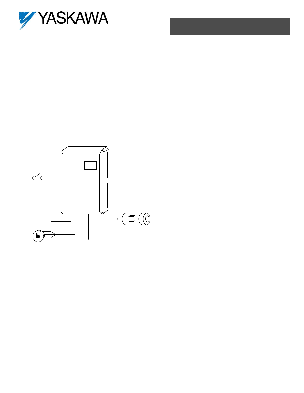
For GPD 515 Adjustable Frequency Drives
1000 Hz Output Frequency
FLASH Memory Software Option
Part Number: GPD515C-XXXX-CS004
(1)
(1)
XXXX refers to the base Model Number of
the drive in which the software is installed.
GPD
515
STOP
RUN
Speed
Reference
1000 Hz
AC Motor
Page 2
Added Parameters:
This software does not add any new parameters to the drive.
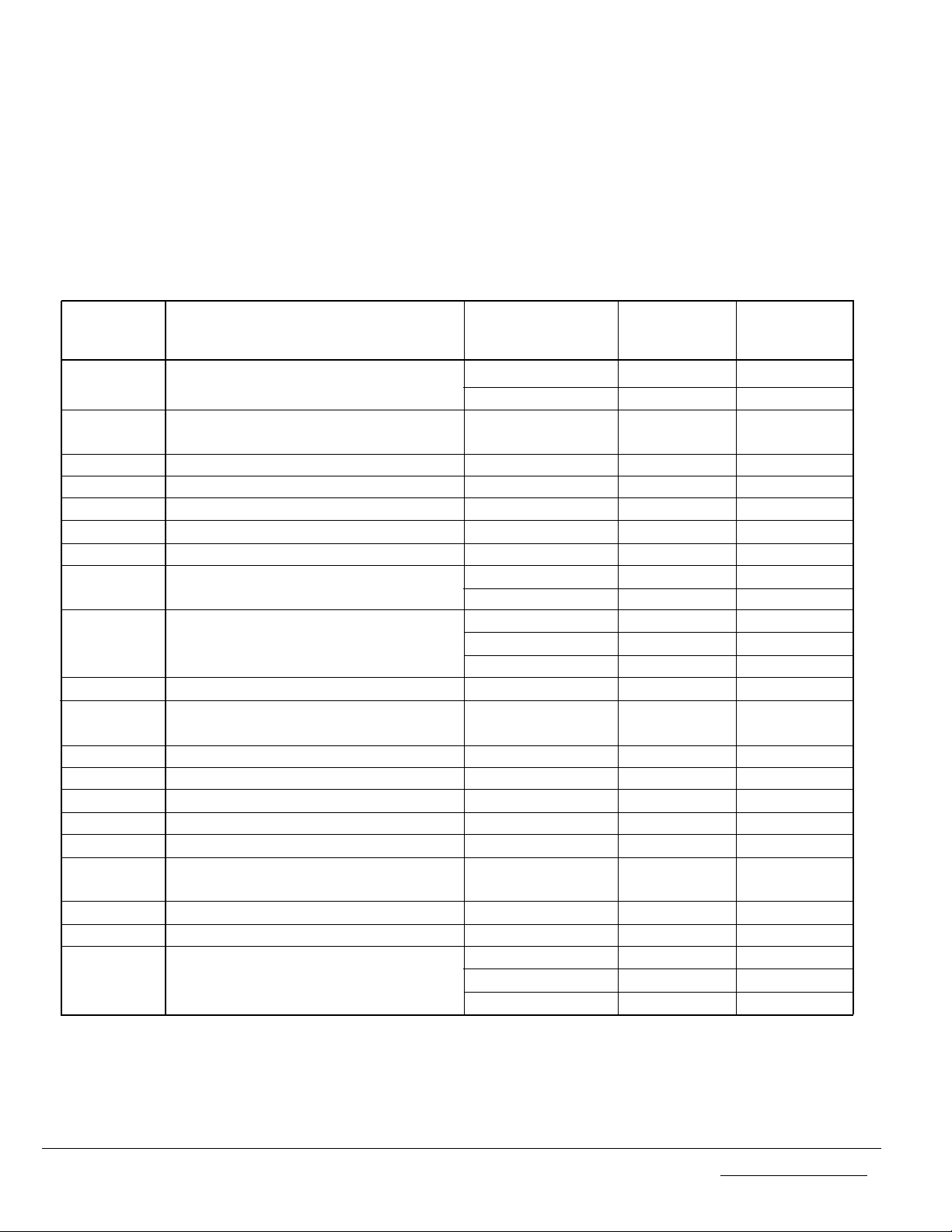
Changed Parameters:
Refer to Appendix 1 ot the GPD 515 Technical Manual, TM 4515. The following changes result from
the installation of this software in the drive.
Parameter Function Name Changed Standard 1000 Hz
Software Software
A1-02 Control Method Selection Max. Value 3 0
Factory Setting 2 0
b3-03 Speed Search Deceleration Min. Value 0.0 1.0
Time
b6-01 Dwell Frequency at Start Max. Value 400.0 1000.0
b6-03 Dwell Frequency at Stop Max. Value 400.0 1000.0
b8-02 Energy Saving Frequency Max. Value 400.0 1000.0
C6-01 Carrier Frequency Upper Limit Max. Value 15.0
(1)
10.0
(1)
C6-02 Carrier Frequency Lower Limit Max. Value 15.0
(1)
10.0
(1)
d1-01 thru Frequency References Max. Value 400.0 1000.0
d1-08 Increment 0.01 0.1
d1-09 Jog Frequency Reference Max. Value 400.0 1000.0
Increment 0.01 0.1
Factory Setting 6.00 60.0
d2-02 Reference Lower Limit Max. Value 100.0 109.0
d3-01 thru Critical Frequency Rejection Max. Value 400.0 1000.0
d3-03
E1-04 Max Frequency Max. Value 400.0 1000.0
E1-06 Base Frequency Max. Value 400.0 1000.0
E1-07 Mid Frequency A Max. Value 400.0 1000.0
E1-09 Min Frequency Max. Value 400.0 1000.0
E1-11 Mid Frequency B Max. Value 400.0 1000.0
H1-01 thru Multi-Function Input Terminal Max. Value 77 66
H1-06 Selection
L2-04 Power Loss V/F Ramp Time Max. Value 2.0 5.0
L4-01 Speed Coincidence Level Max. Value 400.0 1000.0
L4-03 Speed Coincidence Level+– Max. Value 400.0 1000
Min. Value –400.0 –1000
Increment 0.1 1
(1)
Setting will differ depending on drive capacity
Doc. No. 02Y00025-0420 Page 2 of 4 This Page: | Change | 0 | 4/18/97 |
Page 3

Deleted Parameters:
The following parameters are no longer present, and their function descriptions in Section 5 of the
Technical Manual are not applicable:
b1-05 Zero-Speed Operation
b7-01 & b7-02 Droop Control Setup
b9-01 & b9-02 Zero Servo Setup
C3-05 Slip Compensation V/f
C5-01 thru C5-07 Automatic Speed Regulator
C8-08 AFR Gain
C8-30 Carrier in tune
d5-01 thru d5-06 Torque Control Parameters
E2-04, E2-06 thru E2-09 Open Loop Vector Parameters
F1-01 thru F1-14 Pulse Generator / Encoder Setup Parameters
L7-01 thru L7-04 Torque Limits
o1-03 Display Scaling
o1-04 Display Units
Startup Procedure:
1. Set the Parameter Access Level to "Advanced" (Section 2.2C)
(2)
.
2. Set the V/f pattern. This pattern can be a standard (preset) V/f pattern or a custom V/f
pattern. Preset V/f patterns can be found in Table 5-4 (Section 5.48)
(2)
. Apreset V/f pattern is selected by the setting of E1-03. When one of these preset V/f patterns is
employed, parameter E1-01 (Input Voltage Setting) needs to be set at the motor’s nameplate value. If a custom V/f pattern is desired, set E1-03 = F (User Defined V/f) and use
Figure 1 and parameters E1-04 thru E1-13 to set it up (Section 5.48)
(2)
.
Figure 1. V/f Characteristics Set by E1-04 thru E1-13
This Page: | Change | 0 | 4/18/97 | Page 3 of 4 Doc. No. 02Y00025-0420
Vmax
( E1-05 )
VB
( E1-12 )
Vbase
( E1-13 )
OUTPUT
VOLTAGE
VA
( E1-08 )
Vmin
( E1-10 )
Fmin FA Fbase FB Fmax
( E1-09 ) ( E1-07 ) ( E1-06 ) ( E1-11 ) ( E1-04 )
OUTPUT FREQUENCY
Page 4

3. Set the motor’s full load current into parameter E2-01 (Motor Rated Current).
4. Set the JOG frequency (d1-09) to a safe, slow speed (Section 2.2C)
(2)
.
5. Check the motor rotation using the JOG function (Section 2.2C)
(2)
.
6. Further operational tests can be performed by following Section 2.5
(2)
.
(2)
Refer to GPD 515 Technical Manual TM 4515.
Verifying Installed Software Number:
For the 1000 Hz software option, the software number
is 9990, 5112, or 5114. The software version installed
in the drive can be verified by either reading it off of
the control board, the FLASH label, or calling it up on
the Digital Operator.
In order to read the software number off of the control
board, take the cover off of the drive and look for the
white sticker on the main control board. This sticker is
just to the right of connector 2CN. On it is the version
of the control board, then a dash, then the software
number (see Figure 2). The "S" before the number
can be disregarded.
In order to view the software number from the Digital
Operator, bring up drive parameter U1-14 (FLASH ID).
This is done by powering up the drive and using the
following key sequence:
Press , then ,
then , then ,
then 13 times.
NOTICE TO USER:
Be sure to keep this document with your GPD 515 Technical Manual.
Doc. No. 02Y00025-0420 Page 4 of 4 This Page: | Change | 0 | 4/18/97 |
MENU
DATA
ENTER
DATA
ENTER
Figure 2. Software Number Location
on Control Board
 Loading...