

Page 1
For GPD515 Adjustable Frequency Drives
Traverse Control
FLASH Memory Software Option
Part Number: GPD515C-XXXX-CS006
(1)
With this factory-installed FLASH software, the
GPD515 has the ability to modulate the output
frequency around the set frequency reference.
This function provides an evenly wound roll for
those winding applications that would
experience localized build-ups without this
feature. The terms disturb, p-jump, ribbon
break and wobbulator are also used to
describe this function.
Specifications:
• P-Jump Function / Inertia Compensation
• P-Jump ON/OFF Select
• P-Jump Limit
• Adjustable Duty Cycle
• Sawtooth Waveform Generation / Ribbon
Break
• Percent Trim Adjustment
• Independent P-Jump Adjustment
• Independent Accel/Decel Times
• Control Mode: P-Jump in V/f only
• Serial Communications: DeviceNet,
Profibus, Modbus Plus, Modbus RTU.
This document is an addendum to Technical
Manual TM4515, listing the effect of this software on the parameters in the drive and
function descriptions in the manual.
Change 0 4/18/97 Page 1 of 6 Doc. No. 02Y00025-0422
Change 1 9/19/00
(1) XXXX refers to the base Model Number of
the drive in which the software is installed.
Page 2
1.0 Wiring
Wire the incoming power, motor, and accessories and control wiring as specified in the GPD515
Technical Manual TM4515.
Off
(2)
Open = Disturb function enabled
Closed = Disturb function disabled
when Disturb function is enabled
Active
V/f Only
(2)
V/f Only
V/f Only
2.0 I/O Definitions
2.1 New Multi-Function Digital Input Settings
For Parameters H1-01 through H1-06.
Addition to Table 5-2 Multi-Function Input Terminal Data Settings (Section 5.32)
Data Function Description Availability
80 Disturbed Waveform
2.2 New Multi-Function Digital Output Settings
For Parameters F5-01, F5-02 and H2-01 through H2-03.
Addition to Table 5-3 Multi-Function Output Terminal Data Settings (Section 5.33)
Data Function Description Availability
40 Disturb – Up Status Closed during the accelerating period
41 During Disturb Closed when Disturb Function is
2.3 New Multi-Function Analog Input Settings
For Parameters H3-05 and H3-09.
None.
2.4 New Multi-Function Analog Output Settings
For Parameters F4-01, F4-03, H4-01 and H4-04.
None.
(2)
GPD 515 Technical Manual TM4515
Change 0 4/18/97 Page 2 of 6 Doc. No. 02Y00025-0422
Change 1 9/19/00
Page 3

3.0 Startup Procedure
1. Perform the start-up procedure using section 2.2c of the GPD515 technical manual. This
procedure will go through changing the drive into V/f control, and setting up the V/hz pattern.
2. Verify that parameter P1-01 is set to a 1 (Enabled).
3. Adjust parameter P1-02 to the desired amount of disturbed waveform amplitude desired.
This parameter is set as a percentage of the frequency reference.
4. Adjust Parameter P1-03 to the desired amount of disturbed waveform “jump”. This is used
to compensate for the mechanical inertia of the system. This parameter is set as a
percentage of parameter P1-02.
5. Adjust parameters P1-04 and P1-05 to the desired slope times.
6. Done.
4.0 Custom Software Parameters
4.1 New Program Group
Group P
Traverse
4.2 New Program Function
Function P1
Traverse Param
Change 0 4/18/97 Page 3 of 6 Doc. No. 02Y00025-0422
Change 1 9/19/00
Page 4

4.3 New Program Parameters
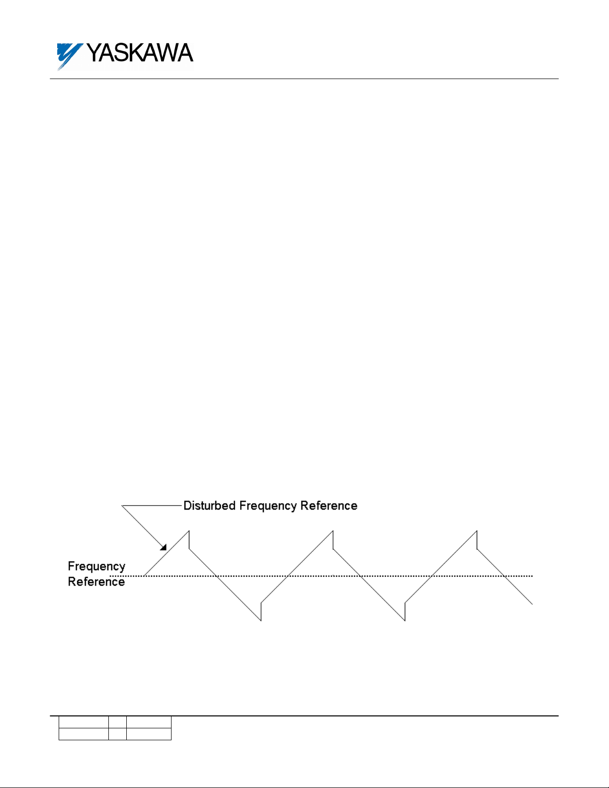
The Traverse (Disturb) function give the drive the ability to change speed in a regular
pattern from a steady frequency reference. Traverse changes the speed of the
motor/winder so that the material being wound build up evenly.
Figure 1: Disturbed Speed Reference When Using the Traverse Function
Disturb WF Sel
Enabled
P1-01 Disturb WF Sel
Setting Range: 0 to 1
Factory Default: 1
Modbus Address: 0580H
Setting Description
0 Disturbed speed reference is disabled
1 Disturbed speed reference is enabled
Change 0 4/18/97 Page 4 of 6 Doc. No. 02Y00025-0422
Change 1 9/19/00
Page 5

Disturb WF Amp
P1-02= 0.0 %
P1-02 Disturb Waveform Amplitude
Setting Range: 0.0 to 20.0%
Factory Default: 0.0%
Modbus Address: 0581H
This parameter determines how much faster or slower than the set frequency reference
(Fref) the actual frequency reference will be. See Figure 1.
Maximum Frequency = Fref + [P1-02 x Fref]
Minimum Frequency = Fref – [P1-02 x Fref]
Disturb WF Jmp
P1-03= 0.0 %
P1-03 Disturb Waveform Jump
Setting Range: 0.0 to 50.0%
Factory Default: 0.0%
Modbus Address: 0582H
This parameter determines hoe much “jump” will occur in the frequency reference, and is
used to compensate for the inertia of the mechanical system. See Figure 1.
Jump Distance = P1-03 x P1-02 x Fref
Change 0 4/18/97 Page 5 of 6 Doc. No. 02Y00025-0422
Change 1 9/19/00
Page 6

Neg Slope Time
P1-04= 0.0 Sec
P1-04 Negative Slope Time
Setting Range: 0.0 to 120.0 Sec.
Factory Default: 0.0 Sec.
Modbus Address: 0583H
Pos Slope Time
P1-05= 0.0 Sec
P1-05 Positive Slope Time
Setting Range: 0.0 to 120.0 Sec.
Factory Default: 0.0 Sec.
Modbus Address: 0584H
These parameters determine the rate at which the speed reference will change during the
“disturb” operation. P1-04 determines the decel time, and P1-05 determines the accel
time. NOTE: The selected accel/decel rates (C1-01 through C1-08) are disabled during
traverse operation. See Figure 1.
5.0 New Monitors
None.
6.0 New Alarm and Fault Codes
None.
Change 0 4/18/97 Page 6 of 6 Doc. No. 02Y00025-0422
Change 1 9/19/00
 Loading...