

Page 1

USER’S MANUAL
InverterWin REV 3.0
AC Inverter Support Software
For GPD505/P5 and GPD506/P5
TM.IW.01
Page 2

N
Thank you for choosing this YASKAWA ELECTRIC AMERICA software product. Proper installation and use of this
software will ensure proper product performance, and will prevent damage to connected inverter products.
Please read this manual thoroughly before using this software product and operate the software and any connected
inverter products with care.
Please refer to the inverter product operation manual for proper handling and care of any connected inverter.
OTICE
1. This manual describes the functions of the product and relations with other products. You
should assume that anything not described in this manual is not possible.
2. Although care has been given in documenting the product, please contact your YASKAWA
1.
ELECTRIC AMERICA representati ve if you have any sugge s t ions on impr oving this manual.
3. The inverter product contains potentially dangerous parts under the cover. Do not attempt to
open the cover under any circumstances. Doing so may result in injury or death and may
damage the product. Never attempt to repair or disassemble the product.
4. We recommend that you add the following precautions to any instruction manuals you prepare
for the system into which the product is being installed or incorporated.
• Precautions on the dangers of high-voltage equipment.
• Precautions on touching the terminals of the inverter product even after power has been
turned OFF. (These terminals are live even with the power turned OFF.)
5. Specifications and functions may be changed without notice in order to improve product
performance.
Items to Check Before Unpacking
Check the following items before removing the product from the package:
• Has the correct product been delivered (i.e., the correct model number and specifications)?
• Has the product been damaged in shipping?
ii
TM.IW.01
Page 3

Notice:
YASKAWA ELECTRIC AMERICA products are created and manufactured for use
according to proper procedures by a qualified operator and only for the purposes
described in this manual.
The following conventions are used to indicate and classify precautions in this manual.
Always heed the information provided with them. Failure to heed precautions can result in
injury to people or damage to property.
DANGER indicates an imminently hazardous situation which, if not avoided, will result in death or
serious injur y.
WARNING indicates a potentially hazardous situation which, if not avoided, could result in death or serious
injury.
Caution indicates a potentially hazardous situation which, if not avoided, may result in minor or moderate
injury, or property damage.
YASKAWA Product Referenc es:
All YASKAWA and YASKAWA ELECTRIC AMERICA products are
capitalized in this manual.
The abbreviation “PC” means Personal Computer, and is not used as an abbreviation
for anything else.
© YASKAWA ELECTRIC AMERICA, 2003
All rights reserved. No part of this publication may be reproduced, stored in a retrieval system, or
transmitted, in any form, or by any means, mechanical, electronic, photocopying, recording, or
otherwise, without the prior written permission of YASKAWA ELECTRIC AMERICA.
No patent liability is assumed with respect to the use of the information contained herein. Moreover, because YASKAWA
ELECTRIC AMERICA is constantly striving to improve its high-quality products, the information contained in this manual
is subject to change without notice. Every precaution has been taken in the preparation of this manual. Nevertheless,
YASKAWA ELECTRIC AMERICA assumes no responsibility for errors or omissions. Neither is any liability assumed for
damages resulting from the use of the information contained in this publicatio n.
iii
TM.IW.01
Page 4

Contents
1 Overview..........................................................................
1-1 Introduction.......................................................................2
1-2 Nomemclature..................................................................3
1-3 New Features for InverterWin 3.0..................................4
2 Installation ......................................................................
2-1 PC Requirements............................................................6
2-2 Installation.......................................................................6
2-3 Connecting the PC to the Inverter....................................8
2-4 Getting Started................................................................9
2-5 Going Online with the Inverter.........................................10
2-6 Going Offline with the Inverter.........................................13
3 Operation.........................................................................
3 - 1 Uploading and Downloading Parameters......................15
3 - 2 Opening an Existing Parameter File..............................16
3 - 3 Saving a Parameter File................................................17
3 - 4 Printing a Parameter File...............................................17
3 - 5 Parameter File Information............................................18
3 - 6 Graphing Inverter Information........................................19
3 - 7 Inverter Fault History.....................................................23
3 - 8 Monitoring Inverter Variables.........................................25
3 - 9 Other Menu Options......................................................28
3-10 Status Bar......................................................................29
4 Appendix..........................................................................
4-1 Software Revision History...............................................32
4-2 Toolbar Icons...................................................................32
4-3 Troubleshooting...............................................................33
iv
TM.IW.01
Page 5

C
h
a
C
h
•••• Overview ••••
1-1 Introduction
1-2 Nomenclature
1-3 New Features for 3.00
a
ptt
p
err
e
1
1
Page 6

1-1 Introduction
!
! InverterWin AC Inverter Support Software
!!
The YASKAWA ELECTRIC AMERICA InverterWin support tool is a Windows based
software package designed to provide a user-friendly interface with the GPD505/P5 and
GPD506/P5 inverters. It provides flexible features not found in the standard digital keypad.
InverterWin AC inverter support software is designed to connect to YASKAWA ELECTRIC
AMERICA products. This support software allows the following:
• Uploading and downloading of inverter parameters
• Saving parameters to a file
• Printing of inverter parameters
• Ability to save/recall application specific parameters
• Viewing of parameters available in each control mode and access level
• Viewing of parameter value ranges and default settings
• Viewing of user adjusted parameter values
Parameters stored in older drive specific support tools are not compatible
with InverterWin series support tools. Parameters downloaded using
"
"
""
Note!
InverterWin series support tools are not compatible other series support
tools.
2
TM.IW.01
Page 7
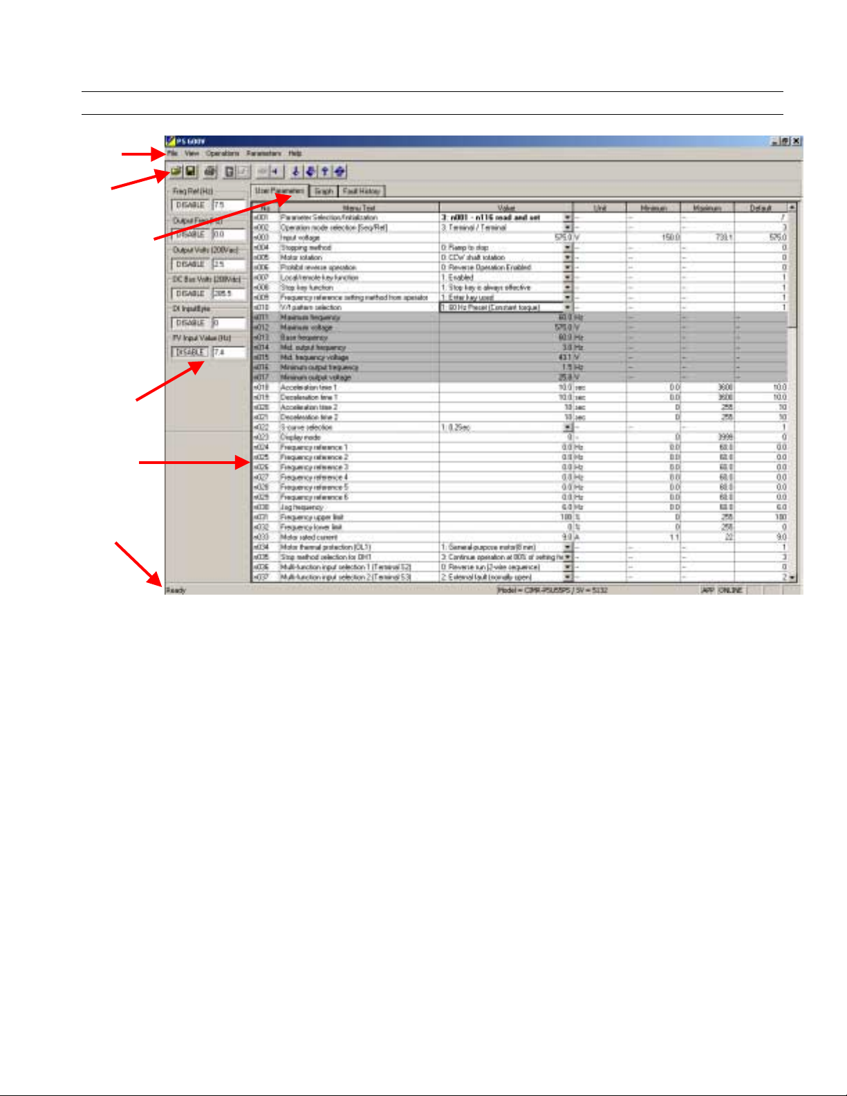
1-2 Nomenclature
Menu Bar
Toolbar
Selection Tabs
Monitor Panel
Main Window
Status Bar
Figure 1.1: InverterWin Screen Nomenclature
3
TM.IW.01
Page 8

1-3 New Features for InverterWin 3.00
The following are new features and changes from InverterWin 2.12 to InverterWin 3.00
1. The number of function selection tabs has been reduced from 4 to 3
2. The Graphing, Monitoring, and Fault History function development has been completed.
3. The inverter status function has been eliminated. The inverter status bits have been added
to the monitoring function.
4. The inverter alarm demo function has been changed to a Fault History function and has
been simplified.
5. The inverter monitor function selections have been expanded for P5 and selections not
available for P5 have been eliminated.
6. The P5 575V product line support has been added
7. The inverter parameter file extensions have been changed as follows:
Inverter Type InverterWin 2.12 InverterWin 3.00 Comment
GPD505/P5 *.P5 *.P5 No Change
GPD506/P5 *.P5 *.P5P File Contents are
identical
GPD506/P5 600V N/A *.P5H New for 575V
The .P5 for GPD506/P5 was changed to .P5P so that the user could tell the files apart. The
GPD506/P5 600V was done in the same manner.
4
TM.IW.01
Page 9

C
h
a
C
h
•••• Installation ••••
2-1 PC Requirements
2-2 Installation
2-3 Connecting the PC
2-4 Getting Started
2-5 Going Online
2-6 Going Offline
a
ptt
p
err
e
2
2
Page 10

Installation Chapter 2
2-1 PC Requirements
!
! InverterWin AC Inverter Support Software requirements for proper installation
!!
and operation
The following are the minimum PC requirements for InverterWin
• Pentium 200MHZ Processor
• 64Mb RAM
• 10 Mb Free disk space
• RS 232 serial port
• CD ROM drive
• 800 x 600 pixel / 256 color display
• Mouse
• Microsoft Windows 2000 , Windows 98, Windows 95, Windows NT SP4 operating
systems. (Windows XP Pending)
2-2 Installation
!
! InverterWin Software Installation from CD-ROM CD4 005
!!
To install InverterWin , please follow these steps below:
1. Close all open programs currently running on the PC to prevent interference with the
installation process.
2. Insert the CD 4005 CD-ROM into the CD-ROM drive (the D: drive for example).
3. If "Autoplay" is enabled, the CD-ROM will automatically start when the CD-ROM is
inserted. The CD ROM navigation menu will appear in a new window on the PC display.
Double click on the large InverterWin Installation button to start the installation
process.
4. If "Autoplay" is not enabled, either of the following methods may be used to start
installation once the CD-ROM is inserted in the PC CD-ROM drive:
• On the Start menu, select Run. Type "D:\InvW in\INSTALL", and then click OK. (If
the CD-ROM drive is not D, replace D with the appropriate CD-ROM drive letter)
• Open the Windows Explorer. Click on drive D. and double click on f ile fold DW.
Double click on the install icon (If the CD-ROM drive is not D: , replace D: with the
appropriate CD-ROM drive letter).
The installation program will start and a welcoming screen will appear.
6
TM.IW.01
Page 11

Installation Chapter 2
!
! InverterWin Software Installation from ZIP File
!!
1. Prior to installation, unzip the file InvWin_v3.00.Zip int o an empty directory. Download unzipping
software from www.pkzip.com or www.winzip.com if necessary. You should find 18 files
unzipped. Those files are as follows:
FILE NAME FILE Name
_inst32i.ex_ Setup.exe
_ISDel.exe Setup.ini
_Setup.dll setup.ins
_sys1.cab setup.lid
_sys1.hdr lang.dat
_user1.cab layout.bin
_user1.hdr os.dat
Data.tag setup.BMP
data1.cab data1.hdr
If any additional files are found, or if the file sizes are incorrect, please run virus scanning
software on the unzipped files, or contact your local YASKAWA ELECTRIC AMERICA
representative.
Run SETUP.EXE from the directory that you unzipped the files in #1 above and follow the
2.
installation instructions. When instructed choose a directory to install the InverterWin software
into.
It is recommended to install the InverterWin software in the default
"
"
""
Note!
3.. Choose a program group for the program icon. While it is not necessary to choose the default
location, it is a good idea to do so. This icon m ay be copied or moved at any time, following the
installation.
4. After the InverterWin software is installed, you will be pr ompted to add an icon on t he desktop.
Choose yes or no, as preferred. After answering, you may begin using the software.
directory chosen during installation. This will prevent problems that may
occur during un-installation.
7
TM.IW.01
Page 12
Installation Chapter 2
2-3 Connecting the PC to the Inverter
!
! InverterWin Connection to Inverter Products
!!
InverterWin may be used with the following YASKAWA ELECTRIC AMERICA inverter
products.
• GPD505/P5
• GPD506/P5
• GPD506/P5 600V
• PC5
This software will not work with inverters provided by other manufacturers. It may not work
with YASKAWA ELECTRIC AMERICA inverters manufactured prior to 1998.
!
!Connecting InverterWin Software on PC to Inverter
!!
The following paragraph describes how to connect your Yaskawa drive to your PC
1. Remove the operator keypad on the front cover of the drive.
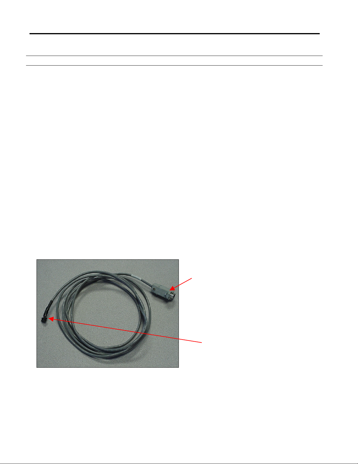
2. Connect cable P/N UWR00103-1 (see Fig 2.1) to the connector for the drive keypad (1CN). Be
careful of the small 12 pin connect as it is keyed (2 ridges on 1 side match the two slots on the
right hand side of the connector.
3. Connect the 9 pin D-sub-miniature to the PC serial port.
Figure 2.1: Inverter Cable P/N UWR00103-1
PC / laptop connection
Inverter connection
8
TM.IW.01
Page 13

Installation Chapter 2
2-4 Getting Started
!
! Starting InverterWin
!!
The following section describes how to start InverterWin .
1. Check to ensure the inverter is on and the communication cable connected
2. Click on the InverterWin icon
The initial main screen will appear after the program finishes loading (Figure 2.2).
Figure 2.2: Opening Screen
9
TM.IW.01
Page 14

Installation Chapter 2
2-5 Going O n line with t he Inverter
• To start the online process, you must first set the communications parameters of
InverterWin correctly so that the PC can communicate with the inverter.
1. Go to the Main Menu and click on View > Communications Settings. The
window in Figure 2.3 will appear.
2. Unless you have modified the settings in the drive you must use the following
default Device Address = 1
Select the serial port on the PC you have connected the Inverter to PC cable.
Most common is to select COM1 and use COM1 or serial port 1 on the PC.
3. Close the Communications setting window
• Now we are ready to go online with the inverter. You can go online by performing any
one of the following operations
1. Go to the main menu, click on Operations > Go Online
Figure 2.3: Communication Settings
2. Push the
button on the toolbar.
10
TM.IW.01
Page 15

Installation Chapter 2
A Device Selection window with a list of all of the inverter types that InverterWin can
communicate with will pop up (Figure 2.4) .
P5 Spec F = GPD506
"
"
""
Note!
Select which inverter you are connected to. The Spec type can be found on the
inverter nameplate located on the side of the inverter. P5 and PC5 that are be A, B, or
C Spec the P5 setting. P5 and PC5 that are F spec use the P5 Spec F setting. Any
P5 that has a model number beginning in a 5 for 575V (example: CIMR-P5U5
the P5 600V selection.
Click on OK and InverterWin will connect with the inverter and upload the current
drive parameters. During the upload a window in will be displayed indicating the
progress of the parameter upload. When finished the screen in Figure 2.6 will be
displayed.
"
"
""
Note!
P5 = GPD505
P5 600V =
GPD506 (600V)
If the communication error window appears after the Device Selection
window: check the communication cable between the drive and the PC is
the correct type and is installed correctly, drive is powered up, and the
communication parameters in InverterWin are set correctly.
Figure 2.4: Device Selection Menu
011 use
Figure 2.5: Communication Error Window
11
TM.IW.01
Page 16

Installation Chapter 2
"
"
""
Note!
Figure 2.6: Main Online Screen
If the inverter loses power while online, connection is resumed once power
is reapplied. It is not necessary to toggle the online status of the
InverterWin software.
12
TM.IW.01
Page 17

Installation Chapter 2
2-6 Goin g Offline with the Inverter
Once connected or online with the inverter, you can go offline or disconnect with the inverter
in one of 3 ways:
1. Click on the
icon on the toolbar
2. Go to the main menu, click on Operations > Go Offline
3. Exit InverterWin.
13
TM.IW.01
Page 18

C
h
a
C
h
a
ptt
p
err
e
3
3
•••• Operation ••••
3-1 Uploading and Downloading
Parameters
3-2 Opening an Existing Parameter File
3-3 Saving a Parameter File
3-4 Printing a Parameter File
3-5 Parameter File Information
3-6 Graphing Inverter Operation
3-7 Monitoring Inverter Alarm Status
3-8 Monitoring Inverter Operation
3-9 Other Menu Options
3-10 Status Bar
Page 19

3-1 Uploading and Downloading Parameters
Before inverter parameters can be uploaded or downloaded, the inverter product type must
be selected, and the inverter must be connected, or brought online, with the InverterWin
software. See Chapter 2 for more information on Operation Online.
Inverter parameters may be uploaded from the inverter or downloaded to the inverter. Once
parameters are uploaded to the PC, they may be saved, printed, or downloaded at any time.
!
! Uploading Parameters to the PC
!!
When the inve rter is brought onlin e, the initial param eter values will be uploaded to the PC.
To upload new parameters to the PC, first determine if only a single parameter should be
read or if all parameters are needed. Click on or Parameters > Read All for all
parameters. Click on or Parameters > Read for individual parameters,
If single read is or individual parameter is selected, only the highlighted parameter will be
read. Otherwise, all parameters will be read and updated. If all parameters are read, then
the progress screen will be displayed. If single read is selected, the progress screen will not
appear.
!
! Downloading Parameters to the Inverter
!!
To download parameters to the Inverter, first determine if only a single parameter should be
sent or if all parameters are needed. Click on or Parameters > Send for individual
parameters, or click on Parameters > Send All for all parameters.
If single send is selected, only the highlighted parameter will be sent to the inverter and
updated in that inverter. Otherwise, all parameters will be sent to the inverter and upda ted.
15
TM.IW.01
Page 20

3-2 Opening an Existing Parameter File
To open an existing file for the current inverter product click on the file open icon or
select File >Open File from the menu. The window in Figure. 3.1 will appear.
Click on the file to be opened, and click on Open, or double-click on the file to be opened.
To change the inverter product file to be selected, click on the down arrow in the Files of
type window. A drop-down selection menu will appear. Click on the appropriate inverter
product to continue.
To find a parameter data file that is not in the current directory, click on the down arrow in
the Look in window. Choose the proper directory, using the mouse. Double-click on the
desired directory to continue.
InverterWin 3.00 uses .P5P file extension instead of .P5 that was used in
InverterWin2.12. The file contents are identical. To open an older .P5
"
"
""
Note!
GPD506 file in InverterWin 3.00 use the “all files” file type selection to
open the file and then save it as a .P5P file if you wish to use the file in
InverterWin 3.00
Figure 3.1: File Open Window
16
TM.IW.01
Page 21

3-3 Saving a Parameter File
To save the current parameter file to floppy or hard drive, click on the file save icon
or select File > Save or File > Save As… from the menu. The followi ng window will
appear.
Figure 3.2: File Save As Wind ow
Enter a file name in the File name window. Click on Save or hit <ENTER> to save the file
with the new name. To save the file in a directory other than the current directory, click on
the down arrow in the Save in window. Double-click on the desired directory to continue.
This saved file can be used to download data to the current inverter or a new inverter. The
data can also be edited and printed at any time, even if the inverter is not connected or
online.
3-4 Printing a Parameter File
To print an existing file for the current inverter product click on the file print icon or
select File > Print from the menu. The current parameter window information will appear.
Selecting File > Print Setup from the menu will allow changes to the printer selection, paper
selection, and other printer properties.
17
TM.IW.01
Page 22

3-5 Parameter File Information
When viewing a parameter file, a window similar to the one below (Figure. 3.3) will be
displayed.
Changed
from Factory
Setting
Not
Available
Figure 3.3: Parameter File Information
InverterWin software will identify parameters that are not available in the current control
mode or access level via gray shading. It will identify parameter default and setting ranges.
All parameters adjusted from default settings will be identified in bold font.
!
! Description of Function Tabs
!!
Function Tab Description Available
User Parameters Parameter file data Anytime
Graph Real-time graph of inverter outputs, or
functions
Monitor
Mode
Fault History Real-time fau lt information When
Online
Table 3.4: Function Tabs
18
TM.IW.01
Page 23

3-6 Graphing Inverter Operation
The Graph function tab is used to graphically plot drive monitor constants during drive
operation. Several functions may be graphed, including:
Parameter Monitored
Value Scale
Frequency
Reference
Output
Frequency
Output
Current
Output
Voltage
DC Bus
Voltage
Elapsed
Time
FV Input
Value
FI Input
Value
0 – Max Freq 100 100% = Max Freq Always frequency regardless
*
0 – Max Freq 100 100% = Max Freq Always frequency regardless
0 – Inv rated
100% = Inv
rated
0 – Max Volts
200V scale
*
0 – 400VDC
400V DC scale
Actual Minutes 100
0 – Max Freq 100 100% input =
0 – Max Freq 100 100% input =
Graphing
Scale
Graphing
display
factor
100 100% = 100%
Inverter rated
amps
100 100% = 300V
100 100% = 400VDC
100%
100%
Comment
of N23 setting
of N23 setting
400V: Monitor 240 = 480V output
600V: Monitor 200 = 575V output
400V: Monitor 300 = 600 VDC
600V: Monitor 300 = 850 VDC
Always frequency
Always frequency
* = Not available when connected to GPD505/P5
Multiple functions can be traced at any point. Up to eight monitors may be used. Different
line colors would be used to track different monitors. See Figure 3.6 for a sample setup
window.
Click on the Graph Setup button or View > Graph Setup on the toolbar to alter the
appearance of the graph. Graph # tabs are used to set up multiple monitors. Click on the
down arrow in the Trace Selection window to choose a function to track. Select a function
from the drop-down list to continue. Line Color may be chosen by the user or by software
default. Line Thickness may be selected to highlight certain monitors as necessary, or to
make them easier to see. The Scale Factor adjusts the scaling of the graphed variable.
100 means that if the inverter variable is at full scale the trace displayed will be 100%.
Table 3.5: Possible Monitors to Graph
19
TM.IW.01
Page 24

After the trace selection has been made, click on OK to display the trace selections next to
the graph.
"
"
""
Note!
Figure 3.6: Graph Setup
The InverterWin software remembers the selections on the graph setup
by inverter type. However, ever time the graph function is used for the first
time after going online with the inverter, each tab of the graph setup
window that you wish to graph will have to be selected by clicking on the
tab to activate that graph function.
20
TM.IW.01
Page 25

Once monitor mode is enabled and trace selection is completed, a screen similar to Figure
3.7 will appear:
Names of
Graphed
Monitors
Figure 3.7: Main Graph Display Window
The InverterWin software must be in Monitor/Status mode, and the inverter
must be online, to use the graph. It must remain in Monitor/Status mode an
"
"
""
Note!
To begin graphing inverter operation click on the Start button beside the graph. The
graph will begin accumulating information and tracking from right to left. Each colored
tracking line represents one of the items to be monitored. Take care not to use the same
color for more than one item, or the graph could become confusing.
The monitor items that are being graphed appear on the right hand side of the
graphing window. The color of the text matches the graph trace color. The number to the
right of the colored text shows the current value of the monitored variable being graphed.
When the graph is stopped, the values will freeze, i.e. they are only updated while the
graph is running. The first time the graph function is used the windows will be blank until
the graph is started.
online, even if the inverter experiences a fault, to continue to review historical
points on the graph.
Current
Values of
Graphed
Monitors
21
TM.IW.01
Page 26

!
! Adjusting the Scale & Timeline
!!
When the graph is tracking, the scale may be adjusted by “pulling” on the anchors on the
X and Y axes. See Figure 3.8 for an example.
Anchors
Figure 3.8: Changing Graph Scale
To find a segment of the graph that has passed out of view, slide the anchors until the
necessary information is disp layed. Pulling the anchors down or to the lef t takes the graph
back to the starting point. Pulling them up or to the righ t moves the scale to the p resent poin t
in time. At various points in the axes the gradients on the scale become closer together or
farther apart. The effect of these variations is to give very precise views of any point in time
on the graph. To print a portion of a graph, click on F
ile > Print. Only the viewable portion of
the graph will be printed. Use the anchors to highlight the appropriate area of the chart, and
the proper resolution.
22
TM.IW.01
Page 27

3-7 Inverter Fault History
The InverterWin software may be used to upload the fault history of the inverter. The
information held in the fault history monitor U-09 is uploaded and displayed in text form.
!
! Using the Fault History Feature
!!
To activate the Inverter Fault History function, the inverter must be online (Refer to
Section 2-4). Click on the Fault-History tab, and a window similar to that in Figure 3.9 will
appear.
Figure 3.9: Initial Fault History Window
23
TM.IW.01
Page 28

To retrieve the fault history information from the inverter, click on the Update button and
the function will retrieve the fault history information from the inverter. A screen similar to
Figure 3.10 will appear. To refresh the information, click on the Update button again.
Figure 3.10: Fault History Inform ation
24
TM.IW.01
Page 29

3-8 Monitoring I n ve rter Operation
The InverterWin software may be used to monitor status of the inverter at any point
while it is online. Many of the inverter monitor parameters available from the inverter
keypad can be monitored from InverterWin. The monitor function, when activated,
opens a new window on the left side of the screen that is always visible when the monitor
mode is active.
!
! Using the Monitor Feature
!!
To use the monitor function, please follow this procedur e:
1. Go online with the inverter.
2. Go to the menu and click on Operations > S
monitor function. A window with the monitored pa rameters will appear on the left
tart Monitor/Status to activate the
hand side of the screen (Figure 3.11). The monitor configuration icon
become active, indicating that the monitored parameters can be changed.
3. If you are using the monitor function for the first time or there are no monitor
parameters selected, the window that opens up on the left side will be blank (See
Figure 3.13).
4. Click on the enable button for each monitor parameter to start/stop the polling of
each monitor parameter. The button toggles in and out to turn off or on that monitor
parameter (Figure 3.12).
Figure 3.11: Monitor Started Figure 3.12: Monitor Started Figure 3.13: Monitor Started
Monitors Enabled Monitors Disabled No Monitors Selected
will
25
TM.IW.01
Page 30

!
! Setting up the Monitor Panel
!!
To set up the monitor panels, click on the monitor bar setup icon or click on View >
Monitor Bar
Setup. The window in Figure 3.14 will appear. Click on the down arrow to the
right of each selection box to select a monitor parameter. A list and description of monitor
parameters is in Table 3.15. The address column on the right hand side of the window is the
MODBUS RAM address for the monitor item.
Figure 3.14: Monitor Bar Setup Window.
26
TM.IW.01
Page 31

Parameter Name Function Range/Scale Comment
Frequency Reference Main frequency reference inside
inverter
Output Frequency Inverter output frequency (U-02) 0 – max Hz
Output Current Inverter output amps 0 – 200% Inv Rated Not amps but %
Output Voltage Inverter output voltage 0 – 250 VAC 400 V & 600V reads in
DC Bus Voltage Inverter DC Bus Voltage 0 – 400 VDC 400 V & 600V reads in
DI Input byte Status of terminal S1 – S6 (U-
07)
Inv Status Byte Inverter status bits (U 08) 0 - 256 Decimal of bits 0 - 7
Elapsed Time (Min) Elapsed time monitor in minutes 0 -65535
PID Feedback Value of PID feedback (U-13) 0 – 60 HZ 60 Hz = 100%
Kwh Monitor Kilowatt hour monitor 0 - 65535
S6 Closed Status of S6 0 - 1 1 = Closed (ON)
S5 Closed Status of S6 0 - 1 1 = Closed (ON)
S4 Closed Status of S6 0 - 1 1 = Closed (ON)
S3 Closed Status of S6 0 - 1 1 = Closed (ON)
S2 Closed Status of S6 0 - 1 1 = Closed (ON)
S1 Closed Status of S6 0 - 1 1 = Closed (ON)
Run bit Status of S6 0 - 1 1 = Closed (ON)
Reverse Run bit Status of S6 0 - 1 1 = Closed (ON)
Inverter Ready Bit Status of S6 0 - 1 1 = Closed (ON)
Inv Fault Bit Inverter Fault Bit 0 –1
MODBUS Write Error MODBUS Parameter Write error 0 -FFFFh Parameter Address
MA –MC Closed Status of MA-MC contact 0 -1
M1-M2 Closed Status of M1-M2 contact 0 -1
Fault and Alarm bits Bit status 0 -1 See program for list
Table 3.15: Monitor parameter selections
0 – max Hz
200 V scale only
200 V scale only
0 - 63 Decimal of bits 0 - 5
27
TM.IW.01
Page 32

3-9 Other Menu Options
InverterWin contains menu options that are not found on the icon toolbar. Some of the
more common menu options ar e foun d bel ow.
!
! Print Setup
!!
Print Setup, located in the F
orientation, and other pri nt param eter s.
!
! Monitor/Parameters Section
!!
Monitor/Parameters Section is located in the View menu and allows access to the monitor
functions and the parameter listings. When toggled off, the operation window is removed and
replaced by a blank background. All toolbars and menus are still viewable when
Monitor/Parame ters Section is toggled off.
!
! Monitor Panel
!!
Monitor Panel is located in the View menu, and allows access to the monitor setup window.
When toggled on, monitor selections can be activated, deactivated and viewed. When
toggled off, the monitor panel is hidden, and more screen space is dedicated to the inverter
graph. See Figure 3.9 for an example of the monitor panel.
!
! About INVWIN
!!
About InvWin… is located under the Help menu, and is used to display information about
the copy of InverterWin that is in use. The software version is displayed in this window.
ile menu, allows changes to the printer, paper size and
Software
Version
Figure 3. 16: About InvWin Window
28
TM.IW.01
Page 33

3-10 Status Bar
InverterWin provides a status bar than displays important information about the software,
and about the connected inverter. The status bar indicates that the inverter is online, what
the inverter model is, and what the software revision is for that inverter.
The status bar also displays “Tool Tips” that offer hints about the functionality of a button or
menu option. See Figure 3.20 for an example Tool Tip.
Figure 3.17: Location of Status Bar
29
Status
Bar
TM.IW.01
Page 34

!
! Status Bar Details
!!
Figure 3.18: Right Hand Side Detail of Status Bar
1
2 3
4
1. Model: This is the model number of the inverter you are connected to or the
opened file is based on.
2. SV = Control card software version number.
3. APP = Application mode (normal) SYS = Factory only mode
4. ONLINE = InverterWin is in the online mode.
Figure 3.19: Left Hand Side Detail of Status Bar
The left hand side of the status bar shows the InverterWin software status or a tool tip
depending on what is going on. Normally it will show either Busy or Ready. When the
cursor is over a specific area of the screen, a tool tip will appear in this space. An example
would be Figure 3.18 when the cursor is on the open file icon.
Figure 3.20: Tool Tip on Left Hand Side
30
TM.IW.01
Page 35

•••• Appendix ••••
4-1 Software Revision History
4-2 Toolbar Icons
4-3 Troubleshooting
Page 36

4-1 Software Revision History
!
! InvWin Revision 2.12
!!
1) Eliminated Parameter save issues when in the offline mode.
!
! InvWin Revision 3.0
!!
Refer to section 1 – 3 for details.
4-2 Toolbar Icons
!
! InvWin Toolbar Icons
!!
Name Description When Available
Open Opens a file User Parameter Mode
Save Saves a file User Parameter Mode or
Print Prints a file or graph User Parameter Mode or
Monitor Bar Setup Allows selection of functions
to monitor
Graph Setup Allows modification of
Operation Online Connects INVWIN software to
Operation Offline Disconnects INVWIN software
Single Send Updates a single parameter in
Send All Updates all parameters in the
Single Read Reads a single parameter in
Read All Reads all parameters in the
graphing functionality
an inverter
from an inverter
the inverter
inverter
the inverter
inverter
Monitor Mode
Monitor Mode
User Parameter Mode or
Monitor Mode
Monitor Mode
When Offline
When Online
When Online
When Online
When Online
When Online
Table 4. 1
32
Page 37

4-3 Troubleshooting
Error Message or
Symptom
Software does not instal l $ Minimum hardware
requirements may not be met
Software will not open after
successful installation
Parameters are missing $ Open loop parameters are not
“Communication Error” $ Inverter is not connected
“Failed the version
verification check!
Version on drive :0”
“Failed to open port” $ Selected PC com port is not
“Internal read error
occurred on file setup.ins.
Unable to load installation
instructions”
“Names” $ Certain .DLL files may be
“The data on the file is for
an inverter that is not
supported by this tool”
“XXXX failed to selfregister”
$ Certain .DLL files may be
missing
available in closed lo op modes
$ Closed loop parameters are
not available in open loop
modes
$ Vector parameters are not
available in V/f modes
properly to PC
$ Baud rate is set improperly
$ Comm port is set improperly
$ Power is removed from the
inverter while onl ine
$ Baud rate is set improperly
$ Comm port is set improperly
$ Inverter CPU version is no t
compatible with INVWIN
software
$ Inverter is not connected
properly to PC
available
$ Other applications are open
while loading INVWIN
$ Security conflict within the PC
prohibiting write access to
setup.ins
missing
$ The data file opened by
INVWIN was created with an
ST series support tool
$ Certain .DLL files may be
missing
Table 4.2: Errors & Error Message
Cause Solution
$ Upgrade the PC
$ Install INVWIN on an alternate
PC
$ Locate and install missing .DLL
files
$ Install Microsoft Access 97 or
2000 and reopen InvWin
$ Verify control method
$ Check cable connecti ons
$ Check INVWIN Baud rate
$ Verify Comm port selection
$ Reapply power to the inverter if
it is lost
$ Check INVWIN Baud rate
$ Verify Comm port selection
$ Use another support tool
$ Use another inverter
$ Check cable connecti ons
$ Try another com port
$ Close any open applications
before installing INVWIN
$ Make sure any required
administrative privileges are
enabled on the PC for install ing
software
$ Locate and install missing .DLL
files
$ Install Microsoft Access 97 or
2000 and reopen InvWin
$ Open the file with an ST series
support tool
$ Create a new data file using
INVWIN
$ Locate and install missing .DLL
files
$ Install Microsoft Access 97 or
2000 and reopen InvWin
33
 Loading...