

Page 1

Table of Contents
1. INTRODUCTION ...................................................................................................................................3
2. HARDWARE INSTALLATION..............................................................................................................4
2.1 O
2.2 D
2.3 N
PTION CARD MOUNTING..................................................................................................................4
RIVE SET-UP ..................................................................................................................................6
ETWORK CONNECTION....................................................................................................................7
2.3.1 Bus Terminating Resistor........................................................................................................7
2.4 N
ETWORK ADDRESSING ....................................................................................................................7
3. APPLICATION OVERVIEW................................................................................................................ 10
3.1 A
3.2 A
3.3 B
3.4 B
NALOG INPUT OBJECT SUMMARY...................................................................................................10
NALOG OUTPUT OBJECT SUMMARY ............................................................................................... 11
INARY INPUT OBJECT SUMMARY....................................................................................................11
INARY OUTPUT OBJECT SUMMARY.................................................................................................11
4. STANDARD OPERATION..................................................................................................................13
4.1 D
RIVE CONFIGURATION................................................................................................................... 13
4.1.1 Accel/Decel Times – AO2, AO3............................................................................................13
4.1.2 PID Configuration – AO4, AO5, AO9....................................................................................13
4.1.3 Stall Prevention – AO6, AO7.................................................................................................13
4.1.4 Operational Mode – AO8.......................................................................................................14
4.1.5 Speed Command Limits – AO10, AO11 ...............................................................................14
4.1.6 Motor Rated Current – AO12................................................................................................14
4.1.7 Prohibit Frequencies – AO13, AO14, A015.......................................................................... 15
4.1.8 Automatic Restarts – AO16...................................................................................................15
4.1.9 Display Units – AO17............................................................................................................15
4.1.10 Power Loss Ride-Through – AO18.......................................................................................16
4.1.11 General Purpose Setup – AO22, AO23................................................................................16
4.2 D
RIVE COMMAND AND CONTROL......................................................................................................17
4.2.1 Run/Stop Command – BO1...................................................................................................17
4.2.2 Speed Command – AO1.......................................................................................................17
4.2.3 Forward/Reverse Command – BO2...................................................................................... 17
4.2.4 Fault/Fault Reset Commands – BO3, BO4...........................................................................17
4.2.5 MultiFunction Input Commands – BO5, BO6, BO7, BO8 .....................................................18
4.2.6 Panel Lock Command – BO9................................................................................................18
4.2.7 Terminal S1 Run/Stop Control .............................................................................................. 18
4.3 D
RIVE MONITORING ........................................................................................................................19
4.3.1 Operating Status – AI1-AI13, BI1-BI8...................................................................................19
4.3.2 Current Rating – AI14............................................................................................................20
4.3.3 Reading Other Parameters – AO21, AI15.............................................................................20
4.4 C
ABLE LOSS BEHAVIOR...................................................................................................................21
4.4.1 Continue Running at Last Speed..........................................................................................21
4.4.2 Continue Running at Preset Speed.......................................................................................21
4.4.3 Stop Running.........................................................................................................................22
4.4.4 Fault.......................................................................................................................................22
5. BYPASS APPLICATIONS ..................................................................................................................23
5.1 T
YPICAL PARAMETER SETTINGS ......................................................................................................23
6. PARAMETER MANAGEMENT FUNCTIONS.....................................................................................24
6.1 S
6.2 R
6.3 C
AVE PARAMETERS ........................................................................................................................24
ESTORE PARAMETERS ..................................................................................................................24
OMPARE PARAMETERS..................................................................................................................25
7. DIAGNOSTIC LEDS............................................................................................................................ 26
TM4028 7/12/2001
Page 2

7.1 RXD..............................................................................................................................................26
7.2 TXD...............................................................................................................................................26
7.3 FAULT ..........................................................................................................................................26
TM4028 7/12/2001
2
Page 3

1. Introduction
The Metasys® N2 communication option for the GPD505 and GPD506/P5 allows these drives to be
integrated into a new or existing Metasys
This manual describes the steps necessary for hardware installation, network identification, and operation
of the interface. Refer to the appropriate Technical Manual for additional information regarding drive
operation and setup.
®
environment.
TM4028 7/12/2001
3
Page 4
2. Hardware Installation
This section describes steps necessary to install the option card and configure the drive for its use. Since
this option is available pre-installed or in kit form, many of these steps may have been completed at the
factory. If already installed, users should still review these steps to become familiar with the procedure.
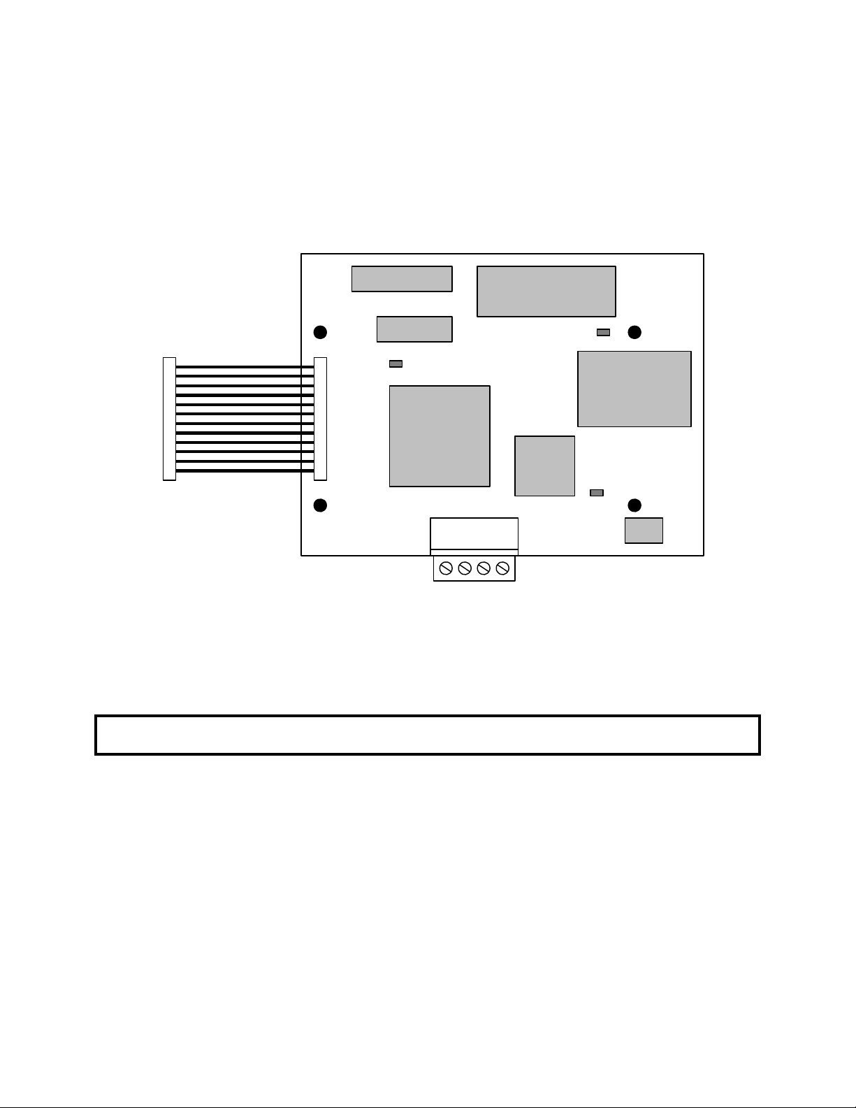
Refer to Figure 1 for the physical location of switches, LEDs and connectors.
2.1 Option Card Mounting
S1
EPROM
S2
RXD
CPU
Figure 1. Option Card Layout
TXD
DC-DC
CONV
UART
FAULT
S3
CAUTION: Make sure that the input power to the drive is TURNED OFF and the CHARGE lamp
inside the unit is OFF before installing the option card.
Step 1. Remove the digital operator, applying pressure to the locking plate on its lower right side, as
illustrated in Figure 2. Lift the operator out by pulling forward.
TM4028 7/12/2001
4
Page 5
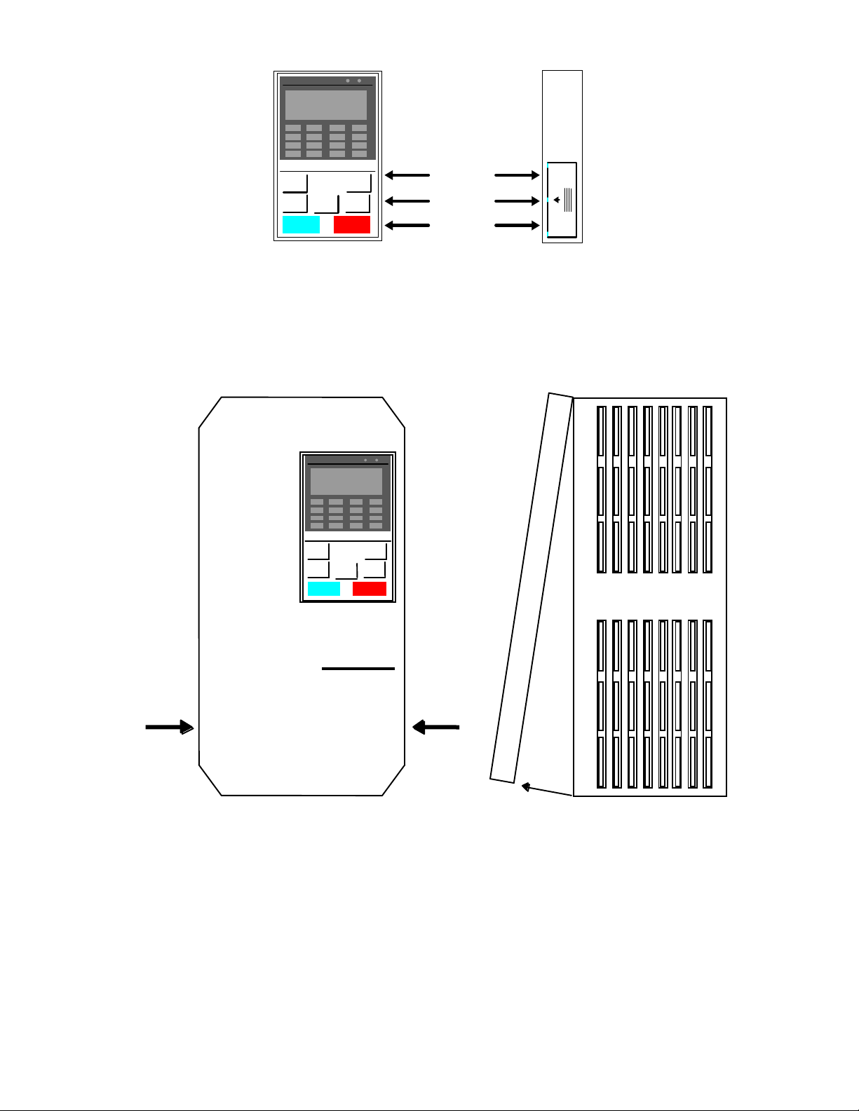
Locking
Plate
Figure 2. Operator Removal
Step 2. Remove the drive cover, applying pressure to the locking tabs on either side of the cover as
illustrated in Figure 3. With the locking tabs disengaged, pivot the cover out from the bottom.
Continue pivoting it until the top hinge disengages.
Press
GPD
506/P5
Press
Figure 3. Cover Removal
Step 3. Position the option card so that the 12-pin interface cable is to the left, as illustrated in Figure 4.
Carefully press the attached cable connector into connector 2CN until it is firmly seated.
Please note the orientation of the locking tab relative to the connector mounted on the control
board.
Step 4. Position the option board mounting holes directly over the four standoffs on the control board.
Carefully press the option board onto the standoffs until it is firmly seated.
TM4028 7/12/2001
5
Page 6
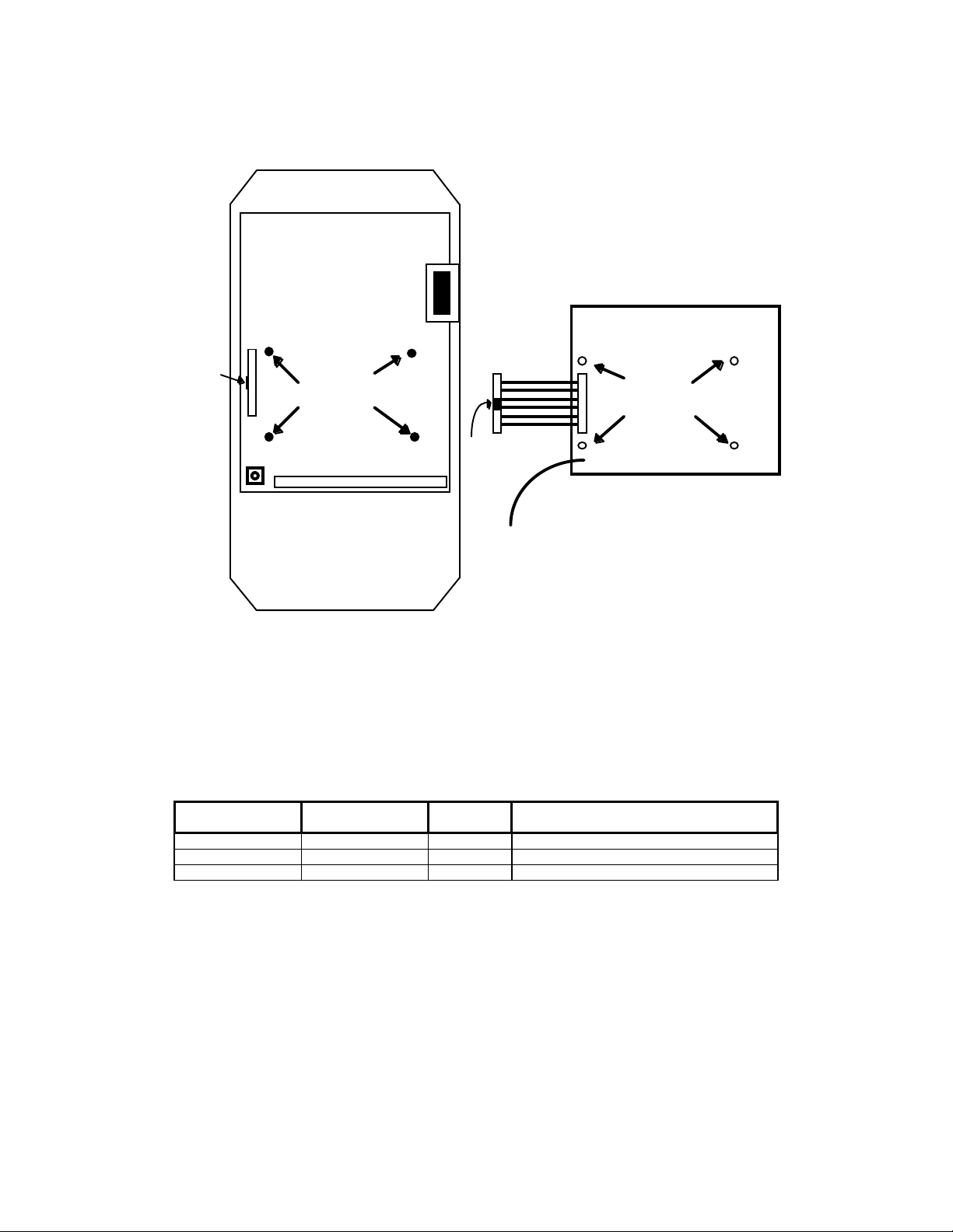
Step 5. Route the green pigtail lead from the option board to the lower left corner of the control board
and connect it to screw terminal E(G).
2CN
Locking Tab
Standoffs
E(G)
Cable
connector
Mounting Holes
Locking Tab
GND
Figure 4. Option Card Positioning
2.2 Drive Set-up
The drive must be properly configured to communicate with the option card, as described below:
GPD505
Parameter
n106 n104 1 Address (01)
n107 n105 2 Baud Rate (9600)
n108 n106 0 Parity (None)
NOTE: Parameter n001 must be set to 3 to change these parameters. New settings will not take
affect until drive power is cycled.
If any of these settings are incorrect, “CALL” will blink on the digital operator, as will the RXD, TXD and
FAULT LEDs. This is an indication that the drive has not yet established communication with the option
card. Once the drive has properly exchanged messages with the option card, all blinking should stop.
GPD506
Parameter
Setting Description
TM4028 7/12/2001
6
Page 7

2.3 Network Connection
Communication on the network is half-duplex, two-wire RS-485, with communication parameters fixed at
9600 baud, eight data bits, no parity and one start/stop bit. The connection medium is shielded twisted pair
cable.
Network connection is facilitated by a pluggable 4-way Phoenix-style connector, as illustrated in Figure 5.
Particular attention should be given to the polarity of the network connection. Proper communication
cannot be established with these terminals reversed.
S
R
E
F
N
N
-
+
H
L
D
Figure 5. Network Connector
2.3.1 Bus Terminating Resistor
A bus terminating resistor (120Ω) is available on each option board and can be applied to the bus by setting
the switches of S3 to their ON position.
In a multi-node system, only those nodes at the end of a bus segment should have terminating resistors.
Before applying a terminating resistor as described above, care should be taken to understand the physical
layout of the network and where other resistors might already be applied. An overloaded bus may not
function properly.
2.4 Network Addressing
A drive’s network address is assigned by selecting the proper setting for switch S1, as detailed in Table 1:
TM4028 7/12/2001
7
Page 8

Network
Address
N/A 00000000 64 01000000 128 10000000 192 11000000
1 00000001 65 01000001 129 10000001 193 11000001
2 00000010 66 01000010 130 10000010 194 11000010
3 00000011 67 01000011 131 10000011 195 11000011
4 00000100 68 01000100 132 10000100 196 11000100
5 00000101 69 01000101 133 10000101 197 11000101
6 00000110 70 01000110 134 10000110 198 11000110
7 00000111 71 01000111 135 10000111 199 11000111
8 00001000 72 01001000 136 10001000 200 11001000
9 00001001 73 01001001 137 10001001 201 11001001
10 00001010 74 01001010 138 10001010 202 11001010
11 00001011 75 01001011 139 10001011 203 11001011
12 00001100 76 01001100 140 10001100 204 11001100
13 00001101 77 01001101 141 10001101 205 11001101
14 00001110 78 01001110 142 10001110 206 11001110
15 00001111 79 01001111 143 10001111 207 11001111
16 00010000 80 01010000 144 10010000 208 11010000
17 00010001 81 01010001 145 10010001 209 11010001
18 00010010 82 01010010 146 10010010 210 11010010
19 00010011 83 01010011 147 10010011 211 11010011
20 00010100 84 01010100 148 10010100 212 11010100
21 00010101 85 01010101 149 10010101 213 11010101
22 00010110 86 01010110 150 10010110 214 11010110
23 00010111 87 01010111 151 10010111 215 11010111
24 00011000 88 01011000 152 10011000 216 11011000
25 00011001 89 01011001 153 10011001 217 11011001
26 00011010 90 01011010 154 10011010 218 11011010
27 00011011 91 01011011 155 10011011 219 11011011
28 00011100 92 01011100 156 10011100 220 11011100
29 00011101 93 01011101 157 10011101 221 11011101
30 00011110 94 01011110 158 10011110 222 11011110
31 00011111 95 01011111 159 10011111 223 11011111
32 00100000 96 01100000 160 10100000 224 11100000
33 00100001 97 01100001 161 10100001 225 11100001
34 00100010 98 01100010 162 10100010 226 11100010
35 00100011 99 01100011 163 10100011 227 11100011
36 00100100 100 01100100 164 10100100 228 11100100
37 00100101 101 01100101 165 10100101 229 11100101
38 00100110 102 01100110 166 10100110 230 11100110
39 00100111 103 01100111 167 10100111 231 11100111
40 00101000 104 01101000 168 10101000 232 11101000
41 00101001 105 01101001 169 10101001 233 11101001
42 00101010 106 01101010 170 10101010 234 11101010
43 00101011 107 01101011 171 10101011 235 11101011
44 00101100 108 01101100 172 10101100 236 11101100
45 00101101 109 01101101 173 10101101 237 11101101
46 00101110 110 01101110 174 10101110 238 11101110
47 00101111 111 01101111 175 10101111 239 11101111
48 00110000 112 01110000 176 10110000 240 11110000
49 00110001 113 01110001 177 10110001 241 11110001
50 00110010 114 01110010 178 10110010 242 11110010
51 00110011 115 01110011 179 10110011 243 11110011
52 00110100 116 01110100 180 10110100 244 11110100
53 00110101 117 01110101 181 10110101 245 11110101
54 00110110 118 01110110 182 10110110 246 11110110
55 00110111 119 01110111 183 10110111 247 11110111
56 00111000 120 01111000 184 10111000 248 11111000
57 00111001 121 01111001 185 10111001 249 11111001
58 00111010 122 01111010 186 10111010 250 11111010
59 00111011 123 01111011 187 10111011 251 11111011
60 00111100 124 01111100 188 10111100 252 11111100
61 00111101 125 01111101 189 10111101 253 11111101
62 00111110 126 01111110 190 10111110 254 11111110
63 00111111 127 01111111 191 10111111 255 11111111
S1 Setting
87654321
Network
Address
S1 Setting
87654321
Network
Address
S1 Setting
87654321
Network
Address
S1 Setting
87654321
Table 1. Network Address Settings
TM4028 7/12/2001
8
Page 9

TM4028 7/12/2001
9
Page 10

A
3. Application Overview
The drive is configured, controlled, and monitored by a comprehensive set of Analog and Binary objects, as
illustrated in Figure 6. Note the convention regarding inputs and outputs (i.e. Network Output = Drive Input,
Network Input = Drive Output).
This chapter summarizes the available objects by their type. Additional detail can be found in Section 4,
Standard Operation, where objects are grouped together by function.
NOTE: The Metasys
®
Change of State (COS) feature is fully supported by this application.
GPD506
Network
Outputs
Network
Outputs
Binary
Objects
nalog
Objects
Network
Inputs
Network
Inputs
Figure 6. Device Overview
3.1 Analog Input Object Summary
Object
ID
AI1 Speed Reference U-01 U-01
AI2 Output Speed U-02 U-02
AI3 Output Current U-03 U-03 A 0
AI4 Kilowatt Hour Meter n/a U-15 kWh 0 9999
AI5 Output Power n/a U-06 kW 0 9999
AI6 Drive Temperature n/a
AI7 PID Feedback n/a U-13
AI8 AC Output Voltage U-04 U-04 V 0
AI9 DC Bus Voltage U-05 U-05 V 0
AI10 Fault Code U-09 U-09 0 8191
AI11 Elapsed Timer – Hrs U-11 U-11 Hr 0 9999
AI12 Elapsed Timer – 10K Hrs U-12 U-12 10K Hr 0 27
AI13 Megawatt Hour Meter n/a U-16 mWh 0 9999
AI14 Drive Rated Current
AI15 Read Parameter Data
Object Name GPD505
Monitor
Note 3 Note 3
Note 4 Note 4 Note 4 Note 4 Note 4
GPD506
Monitor
Note 3
Units Min Max
Note 1
Note 1
°C
Note 1
A
0
0
0
Note 2 Note 2
Notes
1. Value dependent on setting of AO17, Operator Display Mode. Refer to Section 4.1.9.
2. Value dependent on drive capacity. Refer to appropriate Technical Manual.
3. Internal value only available via serial communication.
4. Value depends on the parameter being read (AO21).
Note 1
Note 1
Note 2
Note 1
Note 2
Note 2
TM4028 7/12/2001
10
Page 11

3.2 Analog Output Object Summary
Object
ID
AO1 Speed Command n/a n/a
AO2 Acceleration Time n019 n018 Sec 10.0 0 3600.0
AO3 Deceleration Time n020 n019 Sec 10.0 0 3600.0
AO4 PID Proportional Gain n086 n086 - 1.0 0.0 10.0
AO5 PID Integral Time n087 n087 Sec 10.0 0.0 100.0
AO6 Stall Prevention Level – Run n072 n074 %
AO7 Stall Prevention Level –
AO8 Operational Mode Select n002 n002 - 3 0 8
AO9 PID Mode Select n084 n084 - 0 0 3
AO10 Freq Command Upper Limit n030 n031 % 100 0 109
AO11 Freq Command Lower Limit n031 n032 % 0 0 100
AO12 Motor Rated Current n032 n033 A
AO13 First Prohibit Frequency n058 n062 Hz 0.0 0.0 400.0
AO14 Second Prohibit Frequency n059 n063 Hz 0.0 0.0 400.0
AO15 Prohibit Frequency BW n060 n064 Hz 1.0 0.0 25.5
AO16 Number of Auto Restarts n056 n060 - 0 0 10
AO17 Operator Display Mode n024 n023 - 0 0 3999
AO18 Power Loss Ride-Through n051 n055 - 0 0 2
AO19 Cable Loss Timeout n/a n/a Sec 0 0 3600.0
AO20 Cable Loss Speed n/a n/a
AO21 Read Parameter Number n/a n/a - 0 1 114
AO22 Write Parameter Number n/a n/a - 0 1 114
AO23 Write Parameter Data n/a n/a - 0 0 9999
Object Name GPD505
Parameter
n071 n073 %
Accel
GPD506
Parameter
Units Default Min Max
Note 1
Note 1
0 0
Note 2
Note 2
Note 2 Note 3 Note 3
0 0
30 200
30 200
Note 1
Note 1
Notes
1. Value dependent on setting of AO17, Operator Display Mode. Refer to Section 4.1.9.
2. Value dependent on drive capacity. Refer to appropriate Technical Manual.
3. Proper setting is between 10% and 120% of drive’s output current rating (AI14).
3.3 Binary Input Object Summary
Object
ID
BI1 Run/Stop Monitor 0 Stopped Running
BI2 Forward/Reverse Monitor 0 Forward Reverse
BI3 Drive Ready Monitor 0 Not Ready Ready
BI4 Fault Monitor 0 Not Faulted Faulted
BI5 Drive Comm Error Monitor 0 No Error Drive Comm Error
BI6 Multifunction Output 1 0
BI7 Multifunction Output 2 0
BI8 Safety Interlock Monitor 0 Safety Clear
Object Name Default Off (0)
State
Note 1 Note 1
Note 1 Note 1
(Term S1 closed)
On (1)
State
Safety Set
(Term S1 open)
Notes
1. States are dependent on the setup of the Multifunction Outputs. Refer to appropriate Technical
Manual.
3.4 Binary Output Object Summary
Object
ID
BO1 Run/Stop Command 0 Stop Run
BO2 Forward/Reverse
BO3 Serial Fault (EF0)
Object Name Default Off (0)
State
0 Forward Reverse
Command
0 No Fault Fault
Command
On (1)
State
TM4028 7/12/2001
11
Page 12

Object
ID
BO4 Fault Reset Command 0 No Reset Reset
BO5 Multifunction Input 1 0 Depends on Terminal
BO6 Multifunction Input 2 0 Depends on Terminal
BO7 Multifunction Input 3 0 Depends on Terminal
BO8 Multifunction Input 4 0 Depends on Terminal
BO9 Panel Lock 0 Local/Remote and
B10 Communication Fault
Object Name Default Off (0)
0 EF0 not declared if
Enable
State
S3 function selection
S4 function selection
S5 function selection
S6 function selection
Stop/Reset keys
enabled
cable loss detected
On (1)
State
Depends on Terminal
S3 function selection
Depends on Terminal
S4 function selection
Depends on Terminal
S5 function selection
Depends on Terminal
S6 function selection
Local/Remote and
Stop/Reset keys
disabled
EF0 declared if cable
loss detected
Notes
1. States are dependent on the setup of the Multifunction Inputs. Refer to appropriate Technical Manual.
TM4028 7/12/2001
12
Page 13

4. Standard Operation
The drive interface features 15 Analog Inputs, 23 Analog Outputs, 8 Binary Inputs and 10 Binary Outputs
for configuring, controlling, and monitoring its operation.
This chapter describes each aspect of operation, grouping the objects together by function. Objects are
summarized by type in Section 3, Application Overview.
4.1 Drive Configuration
This section describes the objects used to configure the drive. Refer to the appropriate Technical Manual
for additional information.
4.1.1 Accel/Decel Times – AO2, AO3
These analog outputs define the ramp rates for starting and stopping the motor, configuring the drive as
described below:
Object
ID
AO2 Acceleration Time n019 n018 Sec 10.0 0 3600.0
AO3 Deceleration Time n020 n019 Sec 10.0 0 3600.0
4.1.2 PID Configuration – AO4, AO5, AO9
Object Name GPD505
Parameter
GPD506
Parameter
Units Default Min Max
These analog outputs define the gains and mode of the PID controller. The PID modes selectable by A09
are described below:
AO9 PID Mode
0 PID Disabled
1 PID Enabled
2 PI with Feed Forward
3 Inverted PID
These objects configure the drive as described below:
Object
ID
AO4 PID Proportional Gain n086 n086 - 1.0 0.0 10.0
AO5 PID Integral Time n087 n087 Sec 10.0 0.0 100.0
AO9 PID Mode Select n084 n084 - 0 0 3
Object Name GPD505
Parameter
GPD506
Parameter
Units Default Min Max
4.1.3 Stall Prevention – AO6, AO7
These analog outputs define the stall prevention levels during acceleration and run. Each value is specified
as a percentage of the drive’s current rating (AI14). If the output current (AI3) reaches the specified level
during acceleration or run, the output frequency is maintained or lowered as needed to sufficiently reduce
the output current. These objects configure the drive as described below:
TM4028 7/12/2001
13
Page 14

Object
ID
AO6 Stall Prevention Level – Run n072 n074 %
AO7 Stall Prevention Level –
Object Name GPD505
Parameter
n071 n073 %
Accel
GPD506
Parameter
Units Default Min Max
Note 1
Note 1
30 200
30 200
Notes
1. Value dependent on drive capacity. Refer to appropriate Technical Manual.
4.1.4 Operational Mode – AO8
This analog output defines the source for run and speed commands, as described below:
AO8 Run/Reverse Command
Source
0 Digital Operator Digital Operator AO1, BO1, BO2 have no affect.
1 External Terminals Digital Operator AO1, BO1, BO2 have no affect.
2 Digital Operator External Terminals AO1, BO1, BO2 have no affect.
3 External Terminals External Terminals AO1, BO1, BO2 have no affect.
4 Digital Operator Network AO1 sets speed command.
5 External Terminals Network AO1 sets speed command.
6 Network Network AO1 sets speed command.
7 Network Digital Operator AO1 has no affect.
8 Network External Terminals AO1 has no affect.
Speed Command
Source
Remarks
BO1, BO2 have no affect
BO1, BO2 have no affect
BO1 sets run command.
BO2 sets forward/reverse command.
BO1 sets run command.
BO2 sets forward/reverse command.
BO1 sets run command.
BO2 sets forward/reverse command.
This object configures the drive as described below:
Object
ID
AO8 Operational Mode Select n002 n002 - 3 0 8
Object Name GPD505
Parameter
GPD506
Parameter
Units Default Min Max
4.1.5 Speed Command Limits – AO10, AO11
These analog outputs define the upper and lower speed command limits. Each value is specified as a
percentage of the maximum drive output frequency, defined by GPD505 parameter n012 or GPD506
parameter n011. These objects configure the drive as described below:
Object
ID
AO10 Freq Command Upper Limit n030 n031 % 100 0 109
AO11 Freq Command Lower Limit n031 n032 % 0 0 100
Object Name GPD505
Parameter
GPD506
Parameter
Units Default Min Max
4.1.6 Motor Rated Current – AO12
This analog output defines the current rating of the motor, configuring the drive as described below:
TM4028 7/12/2001
14
Page 15

Object
ID
AO12 Motor Rated Current n032 n033 A
Object Name GPD505
Parameter
GPD506
Parameter
Units Default Min Max
Note 1 Note 2 Note 2
Notes
1. Value dependent on drive capacity. Refer to appropriate Technical Manual.
2. Proper setting is between 10% and 120% of drive’s output current rating (AI14).
4.1.7 Prohibit Frequencies – AO13, AO14, A015
These analog outputs define bands of prohibited frequencies, selected to avoid certain areas of resonant
motor vibration. Two separate bands can be defined, with a common bandwidth. When this feature is
selected, the motor is accelerated and decelerated through the prohibited areas. These objects configure
the drive as described below:
Object
ID
AO13 First Prohibit Frequency n058 n062 Hz 0.0 0.0 400.0
AO14 Second Prohibit Frequency n059 n063 Hz 0.0 0.0 400.0
AO15 Prohibit Frequency BW n060 n064 Hz 1.0 0.0 25.5
Object Name GPD505
Parameter
GPD506
Parameter
Units Default Min Max
4.1.8 Automatic Restarts – AO16
This analog output defines the number of automatic restarts that will be attempted under certain fault
conditions, as described below:
Restartable Faults
• Overcurrent (oC), Overvoltage (ou), Undervoltage (Uu1), Ground Fault (GF)
Non-Restartable Faults
• Overload (oL_), External (EF_), Hardware (CPF_), Fuse Blown (PUF)
• Overcurrent (oC) or Overvoltage (ou) during deceleration
• When Power Loss Ride-Through is disabled (AO18 = 0)
This object configures the drive as described below:
Object
ID
AO16 Number of Auto Restarts n056 n060 - 0 0 10
Object Name GPD505
Parameter
GPD506
Parameter
Units Default Min Max
4.1.9 Display Units – AO17
This analog output defines the display units for speed data (AO1, AO20, AI1, AI2, AI7), as described
below:
AO17 Display Units Description
0 Hz Speed in Hertz (default)
1 %
% of maximum drive frequency, specified by GPD505
TM4028 7/12/2001
15
Page 16

AO17 Display Units Description
parameter n012 or GPD506 parameter n011
2-39 rpm Specifies number of motor poles (P). Speed is calculated by :
40 - 3999 custom Specifies desired reading at maximum output frequency,
N
= 120*f / P.
s
where the lower 3 digits indicate the unscaled reading and the
upper digit places the decimal point. The output frequency
range is linearly converted to this new range. For example:
If the display range is desired to be 0.0 – 14.7, AO17 is set to
1147.
This object configures the drive as described below:
Object
ID
AO17 Operator Display Mode n024 n023 - 0 0 3999
Object Name GPD505
Parameter
GPD506
Parameter
Units Default Min Max
4.1.10 Power Loss Ride-Through – AO18
This analog output defines how the drive will react to a momentary power loss, as described below:
AO18 Ride-Through Mode
0 Ride-Through Disabled
1 Ride-Through Enabled for up to 2 seconds
2 Ride-Through Enabled indefinitely, provided control
power is maintained
This object configures the drive as described below:
Object
ID
AO18 Power Loss Ride-Through n051 n055 - 0 0 2
Object Name GPD505
Parameter
GPD506
Parameter
Units Default Min Max
4.1.11 General Purpose Setup – AO22, AO23
Two analog outputs are defined for setting any drive parameter:
AO22 - Specifies the drive parameter to be set. Writing to this object initiates the write sequence.
AO23 - Specifies the value to be written to the specified parameter. Writing to this object completes the
write sequence and causes the value to be sent to the drive.
Refer to the appropriate Technical Manual for a detailed description of all parameters.
NOTE: The increment listed in the Technical Manual must be considered when specifying a value.
For example, to set GPD506 parameter n070 (GPD505 n066), DC Injection Time at Stop, to 1
second, AO23 must be set to 10, since the increment for this parameter is 0.1 seconds.
TM4028 7/12/2001
16
Page 17

4.2 Drive Command and Control
This section describes the objects used to command and control the drive. Refer to the appropriate
Technical Manual for additional information.
4.2.1 Run/Stop Command – BO1
This binary input controls the run/stop command to the drive, as described below. The drive must be
configured for a network Run/Stop Command (AO8 = 6,7,8) for this input to control the drive.
Object
ID
BO1 Run/Stop Command 0 Stop Run
Object Name Default Off (0)
State
On (1)
State
4.2.2 Speed Command – AO1
This analog input sets the speed command to the drive, as described below. The drive must be configured
for a network Speed Command (AO8 = 4,5,6) for this input to control the drive.
Object
ID
AO1 Speed Command n/a n/a
Object Name GPD505
Parameter
GPD506
Parameter
Units Default Min Max
Note 1
0 0
Note 1
Notes
1. Value dependent on setting of AO17, Operator Display Mode. Refer to Section 4.1.9.
4.2.3 Forward/Reverse Command – BO2
This binary input controls the Forward/Reverse command to the drive, as described below. The drive must
be configured for a network Forward/Reverse Command (AO8 = 6,7,8) for this input to control the drive.
Object
ID
BO2 Forward/Reverse
Object Name Default Off (0)
State
0 Forward Reverse
Command
On (1)
State
4.2.4 Fault/Fault Reset Commands – BO3, BO4
These binary outputs provide fault and fault reset control, as described below. These commands control
the drive for all settings of AO8.
Object
ID
BO3 Serial Fault (EF0)
BO4 Fault Reset Command 0 No Reset Reset
Object Name Default Off (0)
State
0 No Fault Fault
Command
On (1)
State
TM4028 7/12/2001
17
Page 18

4.2.5 MultiFunction Input Commands – BO5, BO6, BO7, BO8
These binary outputs control the multifunction input commands, as described below. These commands are
equivalent to contact closures on external terminals S3 - S6, respectively. Function selection for the
multifunction inputs is configured in GPD505 parameters n036-n039 and GPD506 parameters n037-n040.
Object
ID
BO5 Multifunction Input 1
BO6 Multifunction Input 2
BO7 Multifunction Input 3
BO8 Multifunction Input 4
Object Name Default Off (0)
0 Depends on Terminal
Command
0 Depends on Terminal
Command
0 Depends on Terminal
Command
0 Depends on Terminal
Command
State
S3 function selection
S4 function selection
S5 function selection
S6 function selection
On (1)
State
Depends on Terminal
S3 function selection
Depends on Terminal
S4 function selection
Depends on Terminal
S5 function selection
Depends on Terminal
S6 function selection
NOTE: These objects also report the active state of a multifunction input asserted at the external
terminals (S3 – S6).
4.2.6 Panel Lock Command – BO9
This binary output enables and disables the Local/Remote and Stop/Reset keys of the digital operator, as
described below.
Object
ID
BO9 Panel Lock Command 0 Local/Remote and
Object Name Default Off (0)
State
Stop/Reset keys
enabled
On (1)
State
Local/Remote and
Stop/Reset keys
disabled
4.2.7 Terminal S1 Run/Stop Control
In certain applications, a normally closed system safety may be wired to the drive’s terminal S1. The basis
for this design is a hard-wired run command at terminal S1. If a safety is placed in series with this run
contact, the drive stops when the safety opens.
With this option card, the same functionality can be achieved with a network run command. It is enabled by
setting GPD505 parameter n039 to 19 or GPD506 parameter n040 to 21. With this feature enabled, a
network run command starts the drive only if the contact on S1 is closed. If the contact opens, the drive is
stopped and then restarted once the contact closes.
TM4028 7/12/2001
18
Page 19

4.3 Drive Monitoring
This section describes the objects used to monitor the drive. Refer to the appropriate Technical Manual for
additional information.
4.3.1 Operating Status – AI1-AI13, BI1-BI8
The following table summarizes the input objects available for monitoring the operating status of the drive.
Operating Variable Object ID Description
Speed Reference AI1 Reports the speed reference as commanded from the source selected by
Output Speed AI2 Reports output speed.
Output Current AI3 Reports output current.
Output Power AI5
Drive Temperature AI6
AC Output Voltage AI8 Reports AC output voltage (i.e. voltage applied to motor).
DC Bus Voltage AI9 Reports DC bus voltage.
Kilowatt Hour Meter AI4
Megawatt Hour Meter AI13
PID Feedback AI7
Elapsed Timer – Hrs AI11 Reports cumulative run time in hours.
Elapsed Timer – 10K
Hrs
Fault Code AI10 Reports drive fault status. This value is the decimal equivalent of a binary
Run Status BI1
Forward/Reverse
Status
Drive Ready Status BI3 Reports whether or not the drive is ready to accept a run command
Fault Status BI4
AI12 Reports cumulative run time in increments of 10K hours.
BI2
AO8 (operator, terminal, or network). This allows speed reference to be
monitored even when the network is not the command source.
This value matches AO1 only when the network is selected as the command
source (AO8 = 4,5,6).
Reports output power. This object is only available on GPD506 drives.
Reports drive temperature. This object is only available on GPD506
drives.
Reports cumulative drive energy usage in kilowatts. This object is only
available on GPD506 drives.
Reports cumulative drive energy usage in megawatts. This object is only
available on GPD506 drives.
Reports PID feedback. If PID is disabled, this value will be zero. This
object is only available on GPD506 drives.
fault word. It is the sum of the values associated with each fault bit, as listed
below:
Fault
Bit Value
Overcurrent, Ground, Short Circuit 0 1
Overvoltage 1 2
Drive Overload 2 4
Overheat 3 8
Main Circuit 5 32
Brake Transistor 6 64
External 7 128
Hardware 8 256
Motor Overload 9 512
During Undervoltage 11 2048
Power Loss 12 4096
Phase 13 8192
Reports the run status (1=Run) as commanded from the source selected by
AO8 (operator, terminal, or network). This allows the status to be monitored
even when the network is not the command source.
This value matches BO1 only when the network is selected as the command
source (AO8 = 6,7,8).
Reports the forward/reverse status (1=Reverse) as commanded from the
source selected by AO8 (operator, terminal, or network). This allows the
status to be monitored even when the network is not the command source.
This value matches BO2 only when the network is selected as the command
source (AO8 = 6,7,8).
(1=Ready).
Reports the drive fault status (1=Fault).
TM4028 7/12/2001
19
Page 20

Operating Variable Object ID Description
Multifunction Output 1 BI5
Multifunction Output 2 BI6
Drive Comm Error BI7 Reports the communication status between the option card and the drive
Safety Interlock
(Terminal S1)
BI8 Reports the status of a normally closed safety wired to Terminal S1
Reports the status of Multifunction Output 1 (1=On). The function assigned
to this output is programmed in GPD505 parameter n040 or GPD506
parameter n041.
Reports the status of Multifunction Output 2 (1=On). The function assigned
to this output is programmed in GPD505 parameter n041 or GPD506
parameter n042.
(1=Comm Error).
(1=Safety Set, Term S1 open).
4.3.2 Current Rating – AI14
This analog input reports the current rating of the drive. This information is useful in matching a motor to the
drive and determining the settings for AO6 (Stall Prevention Level during Run), AO7 (Stall Prevention Level
during Accel), and AO12 (Motor Rated Current), all expressed in terms of the drive’s current rating.
4.3.3 Reading Other Parameters – AO21, AI15
Two objects are defined for reading any drive parameter:
AO21 - Specifies the parameter to be read.
AI15 - Reports the value of the specified parameter.
Refer to the appropriate Technical Manual for a detailed description of all parameters.
NOTE: The increment listed in the Technical Manual must be considered when interpreting a
reported value. For example, a read of GPD506 parameter n070 (GPD505 n066), DC
Injection Time at Stop, which reports 10 in AI15 is actually a setting of 1, since the
increment for this parameter is 0.1 seconds.
TM4028 7/12/2001
20
Page 21

4.4 Cable Loss Behavior
This section describes the configurable cable loss feature of the option card. This feature offers a user
maximum flexibility in determining the drive’s response to a loss of communication.
After some interval without receipt of a message, the drive can be configured to respond in one of the
following manners:
• Continue at last speed
• Continue at preset speed
• Stop
• Fault (EF0)
Three points are used to select the desired type of behavior:
• AO19 – Cable Loss Timeout
• AO20 – Cable Loss Speed
• BO10 – Communication Fault Enable
The following table summarizes the settings for each type of behavior (X = don’t care):
Behavior Cable Loss Timeout
(AO19)
Continue at last speed 0 X X
Continue at preset speed Timeout Interval Preset Speed Off
Stop Running Timeout Interval 0 Off
Fault (EF0) Timeout Interval X On
Cable Loss Frequency
(AO20)
Fault Enable
(BO10)
Each behavior is described in additional detail below.
Notes
1. Communication must first be established and then lost for these features to function as described. If a
drive is powered-up without a cable connected or with the master controller offline, a timeout does not
occur.
2. For modes which describe the drive running after a timeout, a run command must have been issued
(BO1 = ‘On’) prior to loss of communications. For safety purposes, it will not automatically start from a
stopped condition. If a user requires the drive to start automatically, additional external wiring may be
added to accomplish this (consult factory).
3. Upon expiration of the timeout interval, the FAULT LED lights and remains lit until communication is
restored.
4.4.1 Continue Running at Last Speed
In this mode, Cable Loss Timeout (AO19) is set to 0, disabling the cable loss feature. The other 2 settings
(BO10, AO20) are ignored. If communication is lost, the drive simply maintains its last commanded state.
4.4.2 Continue Running at Preset Speed
In this mode, Cable Loss Timeout (AO19) is set to the desired interval and Cable Loss Speed (AO20) is set
to the desired preset speed. If the time between messages exceeds the timeout interval, the drive’s speed
command (AO1) is set to the Cable Loss Speed (AO20) and the drive continues running at this new speed.
Communication Fault Enable (BO10) must be set to ‘Off’.
TM4028 7/12/2001
21
Page 22

4.4.3 Stop Running
In this mode, Cable Loss Timeout (AO19) is set to the desired interval and Cable Loss Speed (AO20) is set
to 0. If the time between messages exceeds the timeout interval, the drive’s speed command (AO1) is set
to 0 and the run command (BO1) is set to ‘Off’. Communication Fault Enable (BO10) must be set to ‘Off’.
4.4.4 Fault
In this mode, Cable Loss Timeout (AO19) is set to the desired interval and Communication Fault Enable
(BO10) is set to ‘On’. If the time between messages exceeds the timeout interval, an ‘EF0’ fault is declared
and the drive stops. Cable Loss Speed (AO20) is ignored.
TM4028 7/12/2001
22
Page 23

5. Bypass Applications
For many applications, the drive is integrated into a bypass or engineered package. This type of package
typically features an enclosure with contactors which allow the user to run the motor from line power
(bypass mode) or from the drive (drive mode). This package also provides the flexibility for interfacing
normally closed safety interlocks (firestat, freezestat, vibration sensors, etc.) which stop the drive if the
contacts open.
5.1 Typical Parameter Settings
Because of the widespread use of this type of application, the following parameter set-up table is provided
to aid in the start-up of such a drive.
GPD505
Parameter
n001 3 n001 3 Enables Parameter Write Access
n002 6 n002 6 Operational Mode (Network Control)
n006 1 n006 1 Reverse Run Disabled
n007 0 n007 0 Local/Remote Button Disabled
n019 60 n018 60 Accel Time (secs)..
n020 60 n019 60 Decel Time (secs..
n025 10 n024 10 Initial Reference (Hz)
n026 6 n025 6 Alternate Reference (Hz)
n037 5 n038 5 Terminal S4 Select - Local/Remote
n038 9 n039 10 Terminal S5 Select - Manual Speed
n039 19 n040 21
n051 1 n055 1 Momentary Power Loss
n064 50 n068 50 DC Injection Braking Level (%)
n066 5 n070 5 DC Injection Time at Start (sec)
n103 1 n101 1 Modbus Timeout Enabled
n104 0 n102 0 Ramp to Stop on Modbus Timeout
NOTE: If safety interlocks are interfaced to the bypass package at Terminal S1 and a network run
command is used, Terminal S6 Select must be set as listed to stop the motor if the safety
opens.
GPD505
Setting
GPD506
Parameter
GPD506
Setting
Description
Terminal S6 Select - PID Disable (see note)
TM4028 7/12/2001
23
Page 24

6. Parameter Management Functions
Several parameter management functions have been included with the option card. These functions are
accessed by setting all S1 switches off and using switch S2 to select the desired function, as summarized in
Table 2 below:
Function S1 Setting
(87654321)
Save Parameter Settings ALL OFF 000001 This function saves the current parameter settings to the
Restore Parameter Settings ALL OFF 000010 This function restores the parameter settings to the values
Compare Parameter Settings ALL OFF 000100 This function compares the current parameter settings to
Table 2. User Function Switch Settings
NOTE: These functions detect the current drive type (GPD505/GPD506) as well as that of the image
stored in the option card. If they differ, the functions will not complete and the ERROR LED
will be lit.
6.1 Save Parameters
This function saves the current parameters to the option card.
This feature may be particularly useful to users as a final step in their setup procedure. Once a drive has
been “fine-tuned” for a particular application, its unique setup can be saved for future use. A particular
setup may then be recalled when replacing a drive, copying to other drives, or restoring a setup that has
been altered.
To use this function, the following sequence should be observed:
1. Remove drive power.
2. Remove the network connection.
3. Select the desired function by setting switches S1 and S2 as described in Table 2.
4. Re-apply drive power.
5. Observe the RXD LED flashing. This occurs while the parameters are being read from the drive
and stops when this step is complete.
6. Observe the TXD LED flashing. This occurs while the parameters are being written to the option
card EEPROM and stops when this step is complete.
7. Upon successful completion of this function, the TXD LED remains on and all other LEDs should be
off.
8. Remove drive power.
9. Reset switches S1 and S2 to their usual settings.
10. Attach the network connection.
11. Re-apply drive power.
S2 Setting
(654321)
Description
option card.
saved in the option card.
the values saved in the option card, displaying differences
on the digital operator.
6.2 Restore Parameters
This function restores the parameters to the values saved in the option card.
With a unique drive setup already saved in the option card, this feature may be used when replacing a
drive, copying to other drives, or restoring a setup that has been altered.
TM4028 7/12/2001
24
Page 25

To use this function, the following sequence should be observed:
1. Remove drive power.
2. Remove the network connection.
3. Select the desired function by setting switches S1 and S2 as described in Table 2.
4. Re-apply drive power.
5. Observe the RXD LED flashing. This occurs while the parameters are being read from the option
card EEPROM stops when this step is complete.
6. Observe the TXD LED flashing. This occurs while the parameters are being written to the drive and
stops when this step is complete.
7. Upon successful completion of this function, the TXD LED remains on and all other LEDs should be
off. If any errors occurred, the ERROR LED will be flashing. Monitor U-11 is used to display the
data which failed to be written. The parameter number is displayed first, as ‘ 1 xxx’, where ‘xxx’ is
the parameter number. The next value displayed is the value which failed to be written. The list of
failed parameters is displayed repeatedly until power is removed.
8. Remove drive power.
9. Reset switches S1 and S2 to their usual settings.
10. Attach the network connection.
11. Re-apply drive power.
6.3 Compare Parameters
This function compares the current parameters to the values saved in the option card, displaying
differences on the digital operator.
With a unique drive setup already saved in the option card, this feature may be used to evaluate which
parameters have been changed since the setup was saved. This may be particularly useful in summarizing
parameter changes during a troubleshooting process or determining what changes have been made since
a drive’s initial installation.
To use this function, the following sequence should be observed:
1. Remove drive power.
2. Remove the network connection.
3. Select the desired function by setting switches S1 and S2 as described in Table 2.
4. Re-apply drive power.
5. Observe the RXD LED flashing. This occurs while the parameters are being read from the drive
stops when this step is complete.
6. Observe the TXD LED flashing. This occurs while the current parameter settings are being
compared to the values stored in the option card EEPROM and stops when this step is complete.
7. Upon successful completion of this function, the TXD LED remains on and all other LEDs should be
off if no differences exist. If there are any differences, the ERROR LED will be flashing. Monitor
U-11 is used to display the data which is different. The parameter number is displayed first, as
‘1xxx’, where ‘xxx’ is the parameter number. The next value displayed is the value stored in the
option card EEPROM. These values can be recorded and compared to the current drive settings.
The list of differences is displayed repeatedly until power is removed.
8. Remove drive power.
9. Reset switches S1 and S2 to their usual settings.
10. Attach the network connection.
11. Re-apply drive power.
TM4028 7/12/2001
25
Page 26

7. Diagnostic LEDs
7.1 RXD
This LED is lit under the following conditions:
• While the drive is attempting to establish communication with the option card, the RXD, TXD, and
FAULT LEDs blink in unison and “CALL” blinks on the digital operator. If this condition occurs, repeat
the steps outlined in Section 2.2, Drive Set-up.
• During normal operation with the drive attached and configured on the network, this LED blinks anytime
the drive receives a message addressed to it. Its blinking under these conditions indicates a “healthy”
link between the drive and the network.
• During normal operation with the drive either unattached or unconfigured on the network, this LED
blinks while the option card is communication with the drive. Its blinking under these conditions
indicates a “healthy” link between the drive and the option card.
• During use of the parameter management functions, this LED blinks during the first phase of each
function and is off upon completion (See Section 6, Parameter Management Functions).
7.2 TXD
This LED is lit under the following conditions:
• While the drive is attempting to establish communication with the option card, the RXD, TXD, and
FAULT LEDs blink in unison and “CALL” blinks on the digital operator. If this condition occurs, repeat
the steps outlined in Section 2.2, Drive Set-up.
• During normal operation, this LED blinks anytime the drive is responding to a message from the
network. Its blinking indicates a “healthy” link between the drive and the network.
• During use of the parameter management functions, this LED blinks during the second phase of each
function and remains lit upon completion (See Section 6, Parameter Management Functions).
7.3 FAULT
This LED is lit under the following conditions:
• While the drive is attempting to establish communication with the option card, the RXD, TXD, and
FAULT LEDs blink in unison and “CALL” blinks on the digital operator. If this condition occurs, repeat
the steps outlined in Section 2.2, Drive Set-up.
• During normal operation, this LED is lit if a cable loss is detected (See Section 4.4,
TM4028 7/12/2001
26
Page 27

Cable Loss Behavior). Once communication is re-established, this LED should be off.
• During use of the parameter management functions, this LED blinks if there is data to be read on the
digital operator (See Section 6, Parameter Management Functions).
TM4028 7/12/2001
27
 Loading...