

Page 1

DWG. NO. 02Y00025-0351
SHEET NO. 1 OF 7
EFF. 12/7/93 (m-df)
For GPD 333 230V 1/4-5HP,
460V 1/2-5HP
Adjustable Frequency Drives
CHANGE RECORD
1
STD-5980 2-16-95
DYNAMIC BRAKING (DB) OPTION
(BRAKING RESISTOR (3%) OR
BRAKING RESISTOR UNIT(10%))
(PART NUMBERS DETERMINED BY DRIVE RATING)
Before installing this option, a TECHNICALLY
QUALIFIED INDIVIDUAL who is familiar with this
type of equipment and the hazards involved, should
READ this ENTIRE INSTRUCTION SHEET.
IMPORTANT
This option may have been installed by the
factory. However, certain steps can only be
completed at the installation site. Therefore,
review and perform those steps which
complete the installation process.
DESCRIPTION
Installation of this option enables the motor to be
brought to a smooth and rapid stop. This is achieved
by dissipating the regenerative energy of the AC
motor across the resistive components of the
Dynamic Braking option.
Dynamic Braking Operation
Whenever an excited motor is operated in the
negative slip region (or is subjected to an overhauling
load), the motor will behave as an induction
generator. In this mode, energy will actually flow from
the motor back into the drive, as shown in illustrations
(A) and (B).
This energy will cause the DC Bus voltage to rise.
Another condition that will cause the DC Bus voltage
to rise is when the input voltage to the drive is high.
When the DC Bus voltage reaches a certain level, the
Dynamic Braking option will activate. The option will
actually “shunt” the regenerative energy away from
the Bus capacitors, as shown in illustration (C), and
will dissipate it as heat in the DB resistors. Since the
regenerative energy is dissipated in the DC resistors,
the Overvoltage (OV) trip is prevented; thus the motor
remains excited and continues to produce braking
torque. However, for the high input voltage condition,
an input contactor (1M) should be used (see Figure 4
or Figure 5) to disconnect the drive when the high
input voltage exists for a long period of time.
BUS
CAPS
MOTOR
(A) "MOTORING" POWER FLOW
BUS
CAPS
MOTOR
(C) POWER SHUNTED FROM BUS CAPS
DB OPTION
BUS
CAPS
MOTOR
(B) "GENERATING" POWER FLOW
Page 2

DWG. NO. 02Y00025-0351
SHEET NO. 2 OF 7
EFF. 12/7/93 (m-df)
Refer to Sheet 1 for latest change.
Table 1
Drive Braking Resistor Unit
Voltage HP(CT) Part Number H W D H1 W1 Mtg Screws
1/4 —— — — — — — ——
2 3/4 5P41-0742 13.00 12.00 5.00 9.00 11.00 3/4 (4)
3
1 5P41-0742 13.00 12.00 5.00 9.00 11.00 3/4 (4)
1.5 5P41-0743 13.00 12.00 5.00 9.00 11.00 3/4 (4)
0 3 5P41-0744 13.00 12.00 5.00 9.00 11.00 3/4 (4)
5 5P41-0745 13.00 12.00 5.00 9.00 11.00 3/4 (4)
1/2 —— — — — — — ——
4 3/4 5P41-0752 13.00 12.00 5.00 9.00 11.00 3/4 (4)
6
1.5 5P41-0752 13.00 12.00 5.00 9.00 11.00 3/4 (4)
2 5P41-0753 13.00 12.00 5.00 9.00 11.00 3/4 (4)
0 3 5P41-0754 13.00 12.00 5.00 9.00 11.00 3/4 (4)
5 5P41-0755 13.00 12.00 5.00 9.00 11.00 3/4 (4)
Figure 1. Braking Resistor
(3% Duty Cycle)
RECEIVING
All equipment is tested against defect at the factory.
Report any damages or shortages evident when
equipment is received immediately to the commercial
carrier who transported the equipment. Assistance, if
required, is available from your MagneTek sales
representative.
STORAGE
If the option is not to be installed immediately, it must
be stored under the following conditions:
– Ambient temperature: -10 to +40° C.
– Protected from rain and moisture.
– Free from corrosive gases or liquids.
– Free from dust or metal particles.
– Clean and dry.
– Free from excessive vibration.
Page 3

DWG. NO. 02Y00025-0351
SHEET NO. 3 OF 7
EFF. 12/7/93 (m-df)
Refer to Sheet 1 for latest change.
Figure 2. Braking Resistor Unit
(10% Duty Cycle)
Page 4
DWG. NO. 02Y00025-0351
SHEET NO. 4 OF 7
EFF. 12/7/93 (m-df)
Refer to Sheet 1 for latest change.
INSTALLATION
Preliminary Procedure
WARNING
HAZARDOUS VOLTAGE CAN CAUSE
SEVERE INJURY OR DEATH.
LOCK ALL POWER SOURCES
FEEDING DRIVE IN “OFF” POSITION.
1. Disconnect all electrical power to drive.
2. Remove drive front cover.
3. Verify that voltage has been disconnected by
using a voltmeter to check for voltage at the incoming
power terminals.
NOTE
Since the drive has integral braking transistors, the Dynamic Braking option only requires
addition of the braking resistor (3% duty cycle)
OR the remote-mounting braking resistor unit
(10% duty cycle).
A. Braking Resistor (3% Duty Cycle) Installation
4. The 3% duty cycle braking resistor is
supplied with 6 inch leads, as shown in Figure 1.
5. The braking resistor requires vertical
installation with ample space to achieve high efficiency
cooling.
6. Connect leads from the braking resistor to
drive terminals according to Figure 3 and Figure 4.
NOTE
External control components shown in Figure
5 are not supplied with the option. These
components are necessary for safe operation
of the Dynamic Braking option.
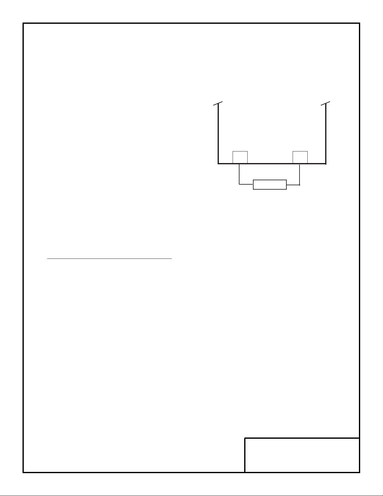
Figure 3. Lead Connections For Braking
Resistor (3% Duty Cycle)
B1/+ B2
BRAKING
RESISTOR
P
B
GPD 333
Page 5

DWG. NO. 02Y00025-0351
SHEET NO. 5 OF 7
EFF. 12/7/93 (m-df)
Refer to Sheet 1 for latest change.
B. Braking Resistor Unit Installation
7. The braking resistor unit requires vertical
installation with ample clearance space (see Figure 2)
to achieve high cooling efficiency.
IMPORTANT
Since the braking resistor unit generates heat
during dynamic braking operation, install it in
a location away from other equipment which
emits heat.
8. Open the braking resistor terminal box for
access to terminals. Connect the braking resistor unit
to the drive according to Table 2 and Figure 5.
ADJUSTMENTS
9. The braking resistor (3% duty cycle) and the
braking resistor unit (10% duty cycle) require drive
re-programming. Program constant
no-20
to
1 X X X
, which disables stall prevention during decel.
10. Reinstall and secure front cover on the drive
and close and secure the terminal box on the the
remote-mount braking resistor unit.
11. Place this instruction sheet with the GPD 333
Technical Manual.
This completes the installation of this option.
Table 2
Terminals B, P 1, 2
✱
Lead Size (AWG) 12-10 18-14
✱
Lead Type 600V ethylene propylene
rubber insulated or equiv.
Terminal Screw M4
✱
Power leads are for the braking resistor unit
generate high levels of electrical noise; these
signal leads must be grouped separately.
NOTE
External control components shown in Figure
5 are not supplied with the option. These
components are necessary for safe operation
of the Dynamic Braking option.
Page 6
DWG. NO. 02Y00025-0351
SHEET NO. 6 OF 7
EFF. 12/7/93 (m-df)
Refer to Sheet 1 for latest change.
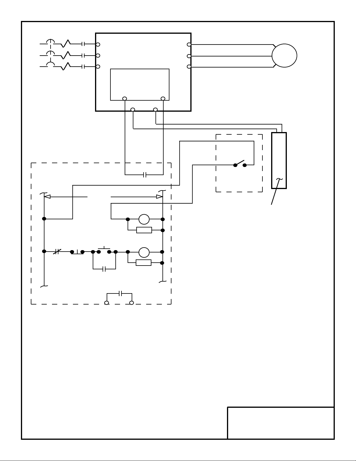
T1T2T3RSTUVW
GPD 333
CONTROL
PCB
46B1/+
B2
PART OF
EXTERNAL
CIRCUIT
BRAKING
RESISTOR
(3% DUTY
CYCLE)
THERMOSTAT
OR OVERLOAD
THRX
1M1M1MCBL1L2L3
120VAC
THRX
FAULT
CONTACT
THRX
RC1MRC1MTHRX
POWER
ON
POWER
OFF
***
CUSTOMER SUPPLIED COMPONENTS
Figure 4. Wiring Braking Resistor (3% Duty Cycle) to Drive
Page 7

DWG. NO. 02Y00025-0351
SHEET NO. 7 OF 7
EFF. 12/7/93 (m-df)
Refer to Sheet 1 for latest change.
T1T2T3RSTUVW
GPD 333
CONTROL
PCB
46B1
B2
PART OF
EXTERNAL
CIRCUIT
BRAKING
RESISTOR
UNIT
(10% DUTY
CYCLE)
BP21THG
THRX
1M1M1MCBL1L2L3
120VAC
THRX
FAULT
CONTACT
THRX
RC1MRC1MTHRX
POWER
ON
POWER
OFF
*
*
CUSTOMER SUPPLIED COMPONENTS
Figure 5. Wiring Braking Resistor Unit (10% Duty Cycle) to Drive
 Loading...