

Page 1
Operator's Manual
Hydrostatic Lawn Tractor
MODEL 791
IMPORTANT: Read safety rules and instructions carefully before operating equipment.
Warning: This unit is equipped with an internal combustion engine and should not be used on or near any unimproved forest-covered, brush-
covered or grass-covered land unless the engine's exhaust system is equipped with a spark arrester meeting applicable local or state laws (if
any), If a spark arrester is used, it should be maintained in effective working order by the operator, In the State of California the above is required
by law (Section 4442 of the California Public Resources Code), Other states may have similar laws, Federal laws apply on federal lands, A spark
arrester for the muffler is available through your nearest engine authorized service dealer or contact the service department, P,O, Box 361131
Cleveland, Ohio 44136-9722,
MTB LLC,P.O.BOX361131CLEVELAND,OHIO44136-9722
PRINTED IN U.S.A. FORM NO. 769-01624A
(1/31/2005)
Page 2
TABLEOFCONTENTS
Content
Customer Support
Important Safe Operation Practices
Tractor Set-up
Controls
Operation
Page Content Page
2 Maintenance 21
3 Service 23
8 Off-season Storage 27
11 Attachments & Accessories 27
14 Warranty Back Cover
FINDINGMODELNUMBER
This Operator's Manual is an important part of your new lawn tractor. Itwill help you assemble, prepare and
maintain the unit for best performance. Please read and understand what it says.
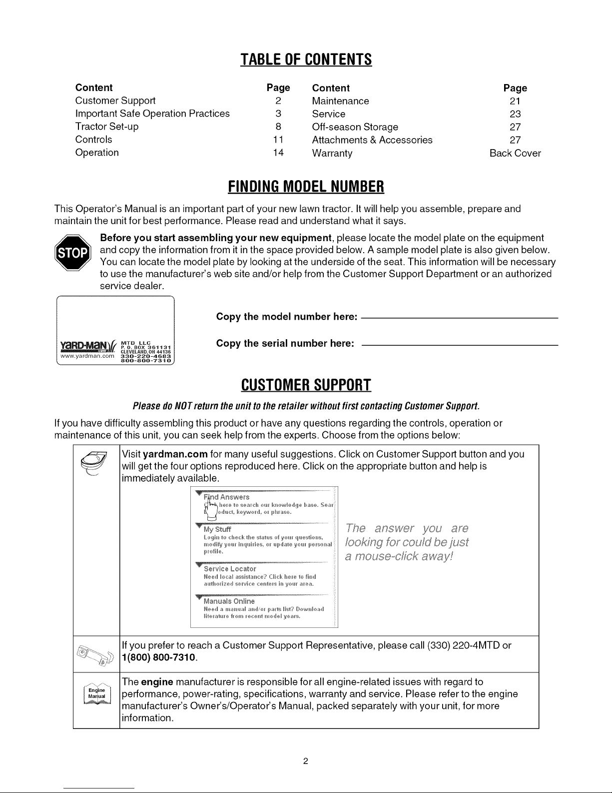
Before you start assembling your new equipment, please locate the model plate on the equipment
and copy the information from it in the space provided below. A sample model plate is also given below.
You can locate the model plate by looking at the underside of the seat. This information will be necessary
to use the manufacturer's web site and/or help from the Customer Support Department or an authorized
service dealer.
Copy the model number here:
IWTD LLC
P. O. BOX 361131
CLEVELAND,OH 44136
338-228-4683
888-888-7316
Copy the serial number here:
CUSTOMERSUPPORT
Please doNOTreturntheunittotheretailer withoutfirstcontactingCustomerSupport.
If you have difficulty assembling this product or have any questions regarding the controls, operation or
maintenance of this unit, you can seek help from the experts. Choose from the options below:
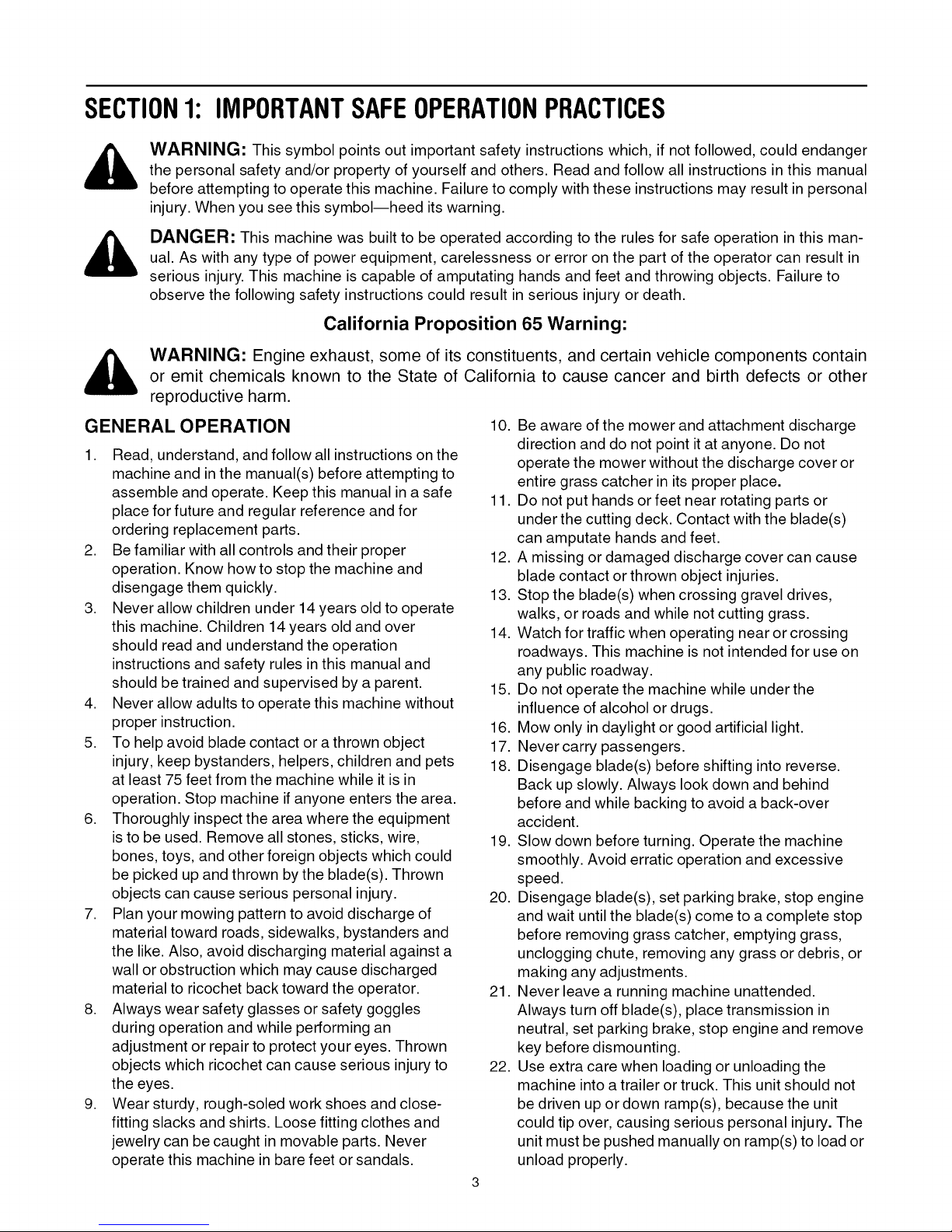
Visit yardman.corn for many useful suggestions. Click on Customer Support button and you
will get the four options reproduced here. Click on the appropriate button and help is
immediately available.
TrendAo_we_
fooking for could be just
a mouse-dick aw_,_y!
If you prefer to reach a Customer Support Representative, please call (330) 220-4MTD or
1(800) 800-7310.
The engine manufacturer is responsible for all engine-related issues with regard to
Ma ual
_En ine
performance, power-rating, specifications, warranty and service. Please refer to the engine
manufacturer's Owner's/Operator's Manual, packed separately with your unit, for more
information.
Page 3
SECTION1: IMPORTANTSAFEOPERATIONPRACTICES
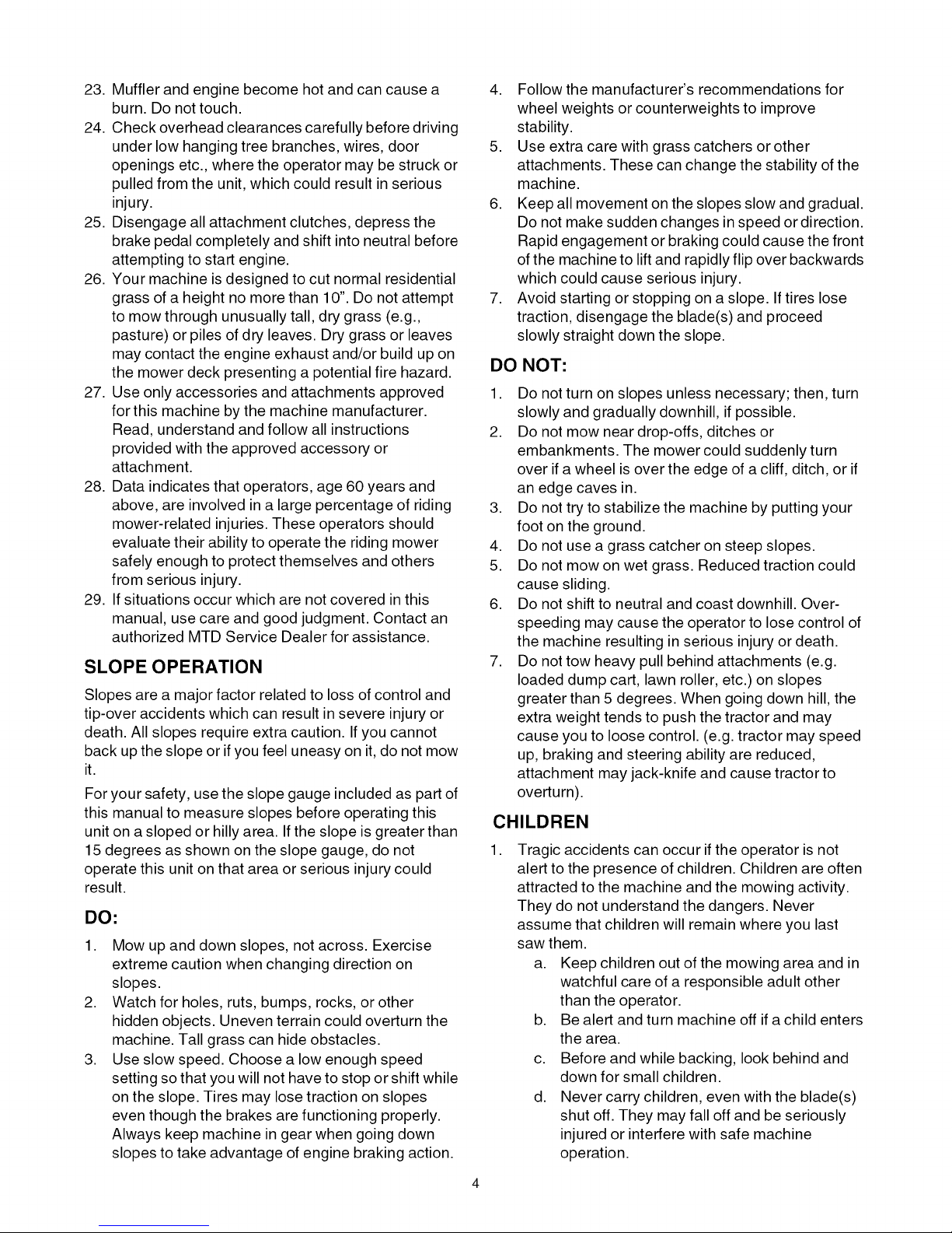
WARNING: This symbol points out important safety instructions which, if not followed, could endanger
the personal safety and/or property of yourself and others. Read and follow all instructions in this manual
before attempting to operate this machine. Failure to comply with these instructions may result in personal
injury. When you see this symbol--heed its warning.
DANGER: This machine was built to be operated according to the rules for safe operation in this man-
ual. As with any type of power equipment, carelessness or error on the part of the operator can result in
serious injury. This machine is capable of amputating hands and feet and throwing objects. Failure to
observe the following safety instructions could result in serious injury or death.
California Proposition 65 Warning:
,_ WARNING: Engine exhaust, some of its constituents, and certain vehicle components contain
GENERAL OPERATION
1. Read, understand, and follow all instructions on the
2. Be familiar with all controls and their proper
3. Never allow children under 14 years old to operate
4. Never allow adults to operate this machine without
5. To help avoid blade contact or a thrown object
6. Thoroughly inspect the area where the equipment
7. Plan your mowing pattern to avoid discharge of
8. Always wear safety glasses or safety goggles
9. Wear sturdy, rough-soled work shoes and close-
or emit chemicals known to the State of California to cause cancer and birth defects or other
reproductive harm.
10. Be aware of the mower and attachment discharge
direction and do not point it at anyone. Do not
machine and in the manual(s) before attempting to
assemble and operate. Keep this manual in a safe
place for future and regular reference and for
ordering replacement parts.
operation. Know how to stop the machine and
disengage them quickly.
this machine. Children 14 years old and over
should read and understand the operation
instructions and safety rules in this manual and
should be trained and supervised by a parent.
proper instruction.
injury, keep bystanders, helpers, children and pets
at least 75 feet from the machine while it is in
operation. Stop machine if anyone enters the area.
is to be used. Remove all stones, sticks, wire,
bones, toys, and other foreign objects which could
be picked up and thrown by the blade(s). Thrown
objects can cause serious personal injury.
material toward roads, sidewalks, bystanders and
the like. Also, avoid discharging material against a
wall or obstruction which may cause discharged
material to ricochet back toward the operator.
during operation and while performing an
adjustment or repair to protect your eyes. Thrown
objects which ricochet can cause serious injury to
the eyes.
fitting slacks and shirts. Loose fitting clothes and
jewelry can be caught in movable parts. Never
operate this machine in bare feet or sandals.
operate the mower without the discharge cover or
entire grass catcher in its proper place.
11. Do not put hands or feet near rotating parts or
under the cutting deck. Contact with the blade(s)
can amputate hands and feet.
12. A missing or damaged discharge cover can cause
blade contact or thrown object injuries.
13. Stop the blade(s) when crossing gravel drives,
walks, or roads and while not cutting grass.
14. Watch for traffic when operating near or crossing
roadways. This machine is not intended for use on
any public roadway.
15. Do not operate the machine while under the
influence of alcohol or drugs.
16. Mow only in daylight or good artificial light.
17. Never carry passengers.
18. Disengage blade(s) before shifting into reverse.
Back up slowly. Always look down and behind
before and while backing to avoid a back-over
accident.
19. Slow down before turning. Operate the machine
smoothly. Avoid erratic operation and excessive
speed.
20. Disengage blade(s), set parking brake, stop engine
and wait until the blade(s) come to a complete stop
before removing grass catcher, emptying grass,
unclogging chute, removing any grass or debris, or
making any adjustments.
21. Never leave a running machine unattended.
Always turn off blade(s), place transmission in
neutral, set parking brake, stop engine and remove
key before dismounting.
22. Use extra care when loading or unloading the
machine into a trailer or truck. This unit should not
be driven up or down ramp(s), because the unit
could tip over, causing serious personal injury. The
unit must be pushed manually on ramp(s) to load or
unload properly.
Page 4
23.Mufflerandenginebecomehotandcancausea
burn.Donottouch.
24.Checkoverheadclearancescarefullybeforedriving
underlowhangingtreebranches,wires,door
openingsetc.,wheretheoperatormaybestruckor
pulledfromtheunit,whichcouldresultinserious
injury.
25.Disengageallattachmentclutches,depressthe
brakepedalcompletelyandshiftintoneutralbefore
attemptingto startengine.
26.Yourmachineisdesignedtocutnormalresidential
grassofaheightnomorethan10".Donotattempt
tomowthroughunusuallytall,drygrass(e.g.,
pasture)orpilesofdryleaves.Drygrassorleaves
maycontacttheengineexhaustand/orbuildupon
themowerdeckpresentingapotentialfirehazard.
27.Useonlyaccessoriesandattachmentsapproved
forthismachinebythemachinemanufacturer.
Read,understandandfollowallinstructions
providedwiththeapprovedaccessoryor
attachment.
28.Dataindicatesthatoperators,age60yearsand
above,areinvolvedinalargepercentageofriding
mower-relatedinjuries.Theseoperatorsshould
evaluatetheirabilitytooperatetheridingmower
safelyenoughtoprotectthemselvesandothers
fromseriousinjury.
29.Ifsituationsoccurwhicharenotcoveredinthis
manual,usecareandgoodjudgment.Contactan
authorizedMTDServiceDealerforassistance.
SLOPE OPERATION
Slopes are a major factor related to loss of control and
tip-over accidents which can result in severe injury or
death. All slopes require extra caution. If you cannot
back up the slope or ifyou feel uneasy on it,do not mow
it.
For your safety, use the slope gauge included as part of
this manual to measure slopes before operating this
unit on a sloped or hilly area. If the slope is greater than
15 degrees as shown on the slope gauge, do not
operate this unit on that area or serious injury could
result.
DO:
1. Mow up and down slopes, not across. Exercise
extreme caution when changing direction on
slopes.
2. Watch for holes, ruts, bumps, rocks, or other
hidden objects. Uneven terrain could overturn the
machine. Tall grass can hide obstacles.
3. Use slow speed. Choose a low enough speed
setting so that you will not have to stop or shift while
on the slope. Tires may lose traction on slopes
even though the brakes are functioning properly.
Always keep machine in gear when going down
slopes to take advantage of engine braking action.
4. Follow the manufacturer's recommendations for
wheel weights or counterweights to improve
stability.
5. Use extra care with grass catchers or other
attachments. These can change the stability of the
machine.
6. Keep all movement on the slopes slow and gradual.
Do not make sudden changes in speed or direction.
Rapid engagement or braking could cause the front
of the machine to lift and rapidly flip over backwards
which could cause serious injury.
7. Avoid starting or stopping on a slope. If tires lose
traction, disengage the blade(s) and proceed
slowly straight down the slope.
DO NOT:
1. Do not turn on slopes unless necessary; then, turn
slowly and gradually downhill, if possible.
2. Do not mow near drop-offs, ditches or
embankments. The mower could suddenly turn
over if a wheel is over the edge of a cliff, ditch, or if
an edge caves in.
3. Do not try to stabilize the machine by putting your
foot on the ground.
4. Do not use a grass catcher on steep slopes.
5. Do not mow on wet grass. Reduced traction could
cause sliding.
6. Do not shift to neutral and coast downhill. Over-
speeding may cause the operator to lose control of
the machine resulting in serious injury or death.
7. Do not tow heavy pull behind attachments (e.g.
loaded dump cart, lawn roller, etc.) on slopes
greater than 5 degrees. When going down hill, the
extra weight tends to push the tractor and may
cause you to loose control. (e.g. tractor may speed
up, braking and steering ability are reduced,
attachment may jack-knife and cause tractor to
overturn).
CHILDREN
,
Tragic accidents can occur if the operator is not
alert to the presence of children. Children are often
attracted to the machine and the mowing activity.
They do not understand the dangers. Never
assume that children will remain where you last
saw them.
a. Keep children out of the mowing area and in
watchful care of a responsible adult other
than the operator.
b. Be alert and turn machine off if a child enters
the area.
c. Before and while backing, look behind and
down for small children.
d. Never carry children, even with the blade(s)
shut off. They may fall off and be seriously
injured or interfere with safe machine
operation.
Page 5
e. Useextremecarewhenapproachingblind
corners,doorways,shrubs,treesorother
objectsthatmayblockyourvisionofachild
whomayrunintothemachine.
f. Toavoidback-overaccidents,always
disengagethecuttingblade(s)before
shiftingintoreverse.The"Reverse
CautionMode" should not be used when
children or others are around.
g. Keep children away from hot or running
engines. They can suffer burns from a hot
muffler.
h. Remove key when machine is unattended to
prevent unauthorized operation.
,
Never allow children under 14 years old to operate
the machine. Children 14 years old and over should
read and understand the operation instructions and
safety rules in this manual and should be trained
and supervised by a parent.
TOWING
1. Tow only with a machine that has a hitch designed
for towing. Do not attach towed equipment except
at the hitch point.
2. Follow the manufacturers recommendation for
weight limits for towed equipment and towing on
slopes.
3. Never allow children or others in or on towed
equipment.
4. On slopes, the weight of the towed equipment may
cause loss of traction and loss of control.
5. Travel slowly and allow extra distance to stop.
6. Do not shift to neutral and coast downhill.
SERVICE
SAFE HANDLING OF GASOLINE:
,
To avoid personal injury or property damage
use extreme care in handling gasoline. Gasoline is
extremely flammable and the vapors are explosive.
Serious personal injury can occur when gasoline is
spilled on yourself or your clothes which can ignite.
Wash your skin and change clothes immediately.
a. Use only an approved gasoline container.
b. Never fill containers inside a vehicle or on a
truck or trailer bed with a plastic liner. Always
place containers on the ground away from
your vehicle before filling.
c. When practical, remove gas-powered
equipment from the truck or trailer and refuel
it on the ground. If this is not possible, then
refuel such equipment on a trailer with a
portable container, rather than from a
gasoline dispenser nozzle.
d. Keep the nozzle in contact with the rim of the
fuel tank or container opening at all times
until fueling is complete. Do not use a nozzle
lock-open device.
e. Extinguish all cigarettes, cigars, pipes and
other sources of ignition.
f. Neverfuel machine indoors.
g. Never remove gas cap or add fuel while the
engine is hot or running. Allow engine to cool
at least two minutes before refueling.
h. Never over fill fuel tank. Fill tankto no more
than _/2inch below bottom of filler neck to
allow space for fuel expansion.
i. Replace gasoline cap and tighten securely.
j. Ifgasoline is spilled, wipe it off the engine
and equipment. Move unit to another area.
Wait 5 minutes before starting the engine.
k. To reduce fire hazards, keep machine free of
grass, leaves, or other debris build-up. Clean
up oil or fuel spillage and remove any fuel
soaked debris.
I. Never store the machine or fuel container
inside where there is an open flame, spark or
pilot light as on a water heater, space heater,
furnace, clothes dryer or other gas
appliances.
m. Allow a machine to cool at least 5 minutes
before storing.
GENERAL SERVICE:
1. Never run an engine indoors or in a poorly
ventilated area. Engine exhaust contains carbon
monoxide, an odorless, and deadly gas.
2. Before cleaning, repairing, or inspecting, make
certain the blade(s) and all moving parts have
stopped. Disconnect the spark plug wire and
ground against the engine to prevent unintended
starting.
3. Periodically check to make sure the blades come to
complete stop within approximately (5) five
seconds after operating the blade disengagement
control. If the blades do not stop within the this time
frame, your unit should be serviced professionally
by an authorized MTD Service Dealer.
4. Check brake operation frequently as it is subjected
to wear during normal operation. Adjust and service
as required.
5. Check the blade(s) and engine mounting bolts at
frequent intervals for proper tightness. Also,
visually inspect blade(s) for damage (e.g.,
excessive wear, bent, cracked).
Replace the blade(s) with the original equipment
manufacturer's (O.E.M.) blade(s) only, listed in this
manual. "Use of parts which do not meet the
original equipment specifications may lead to
improper performance and compromise safety!"
6. Mower blades are sharp. Wrap the blade or wear
gloves, and use extra caution when servicing them.
7. Keep all nuts, bolts, and screws tight to be sure the
equipment is in safe working condition.
Page 6
8. Nevertamperwiththesafetyinterlocksystemor
othersafetydevices.Checktheirproperoperation
regularly.
9. Afterstrikingaforeignobject,stoptheengine,
disconnectthesparkplugwire(s)andground
againsttheengine.Thoroughlyinspectthe
machineforanydamage.Repairthedamage
beforestartingandoperating.
10.Neverattempttomakeadjustmentsorrepairsto
themachinewhiletheengineisrunning.
11.Grasscatchercomponentsandthedischarge
coveraresubjecttowearanddamagewhichcould
exposemovingpartsorallowobjectstobethrown.
Forsafetyprotection,frequentlycheckcomponents
andreplaceimmediatelywithoriginalequipment
manufacturer's(O.E.M.)partsonly,listedinthis
manual."Useofpartswhichdonotmeetthe
originalequipmentspecificationsmayleadto
improperperformanceandcompromisesafety!"
12.
Donotchangetheenginegovernorsettingsor
over-speedtheengine.Thegovernorcontrolsthe
maximumsafeoperatingspeedoftheengine.
13.
Maintainorreplacesafetyandinstructionlabels,as
necessary.
14.
Observeproperdisposallawsandregulationsfor
gas,oil,etc.toprotecttheenvironment.
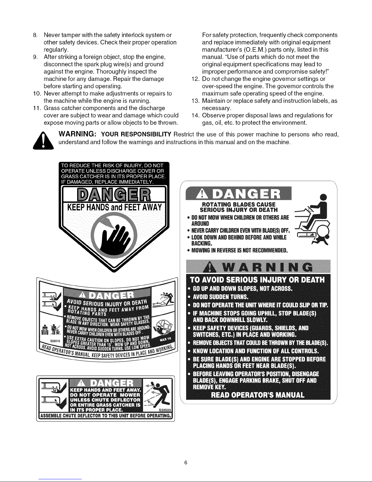
_, ARNING: YOURRESPONSIBILITYRestricttheuseofthispowermachinetopersonswhoread,
understandandfollowthewarningsandinstructionsinthismanualandonthemachine.
®
ROTATING BLADES CAUSE
SERIOUS iNJURY OR DEATH
• DOHOTMOWWHENCHILBREHOROTHERSARE
AROUHD
• HEVERCAP_YCH&DREHEVEHWITHBLADE(S)OFF.
• LOOKDOWNAHDBEHINDBEFOREANDWHILE
BACKING.
o MOWINGiNREVERSEJSHOTRECOMMEHDED.
Page 7

I.LI
I.LI
a.
64
Z
I.LI
_ Sight and hold this levelwith a vertical tree...
15°
Page 8
SECTION3: TRACTORSET-UP
IMPORTANT:Your tractor is shipped with motor oil in the engine. However, you MUST check the oil level before
starting the engine and operating the tractor. Refer to the separate engine manufacturer's Operator/Owner Manual
packed w th your tractor. Read nstruct ons carefu y.
LooseParts
Packaged with this Operator's Manual you'll find:
• One Small Clamp (726-0354)
• One 1/4-20 x 1/2-inch Screw (710-0599)
• One Oil Drain Sleeve (731-1682A)
Store the clamp and screw in a convenient place. Both
will be necessary to properly secure your tractor's wire
harness should you choose to purchase afront-end
attachment for your lawn tractor. Refer to page 27 for a
table of available attachments and accessories.
Refer to page 21 for information regarding the oil drain
sleeve and changing your engine oil.
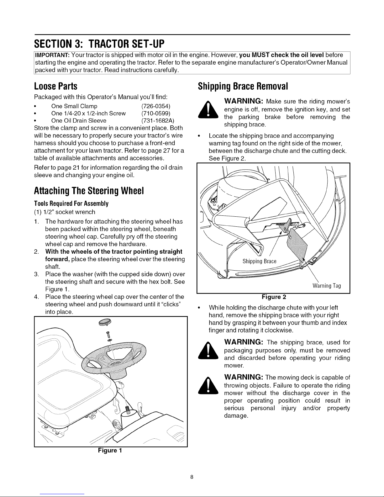
AttachingTheSteeringWheel
ToolsRequiredForAssembly
(1) 1/2" socket wrench
1. The hardware for attaching the steering wheel has
been packed within the steering wheel, beneath
steering wheel cap. Carefully pry off the steering
wheel cap and remove the hardware.
2. With the wheels of the tractor pointing straight
forward, place the steering wheel over the steering
shaft.
3. Place the washer (with the cupped side down) over
the steering shaft and secure with the hex bolt. See
Figure 1.
4. Place the steering wheel cap over the center of the
steering wheel and push downward until it "clicks"
into place.
ShippingBraceRemoval
_, WARNING: Make sure the riding mower's
engine is off, remove the ignition key, and set
the parking brake before removing the
shipping brace.
Locate the shipping brace and accompanying
warning tag found on the right side of the mower,
between the discharge chute and the cutting deck.
See Figure 2.
Warning Tag
Figure 2
While holding the discharge chute with your left
hand, remove the shipping brace with your right
hand by grasping it between your thumb and index
finger and rotating it clockwise.
Figure 1
WARNING: The shipping brace, used for
packaging purposes only, must be removed
and discarded before operating your riding
mower.
WARNING: The mowing deck is capable of
throwing objects. Failure to operate the riding
mower without the discharge cover in the
proper operating position could result in
serious personal injury and/or property
damage.
Page 9
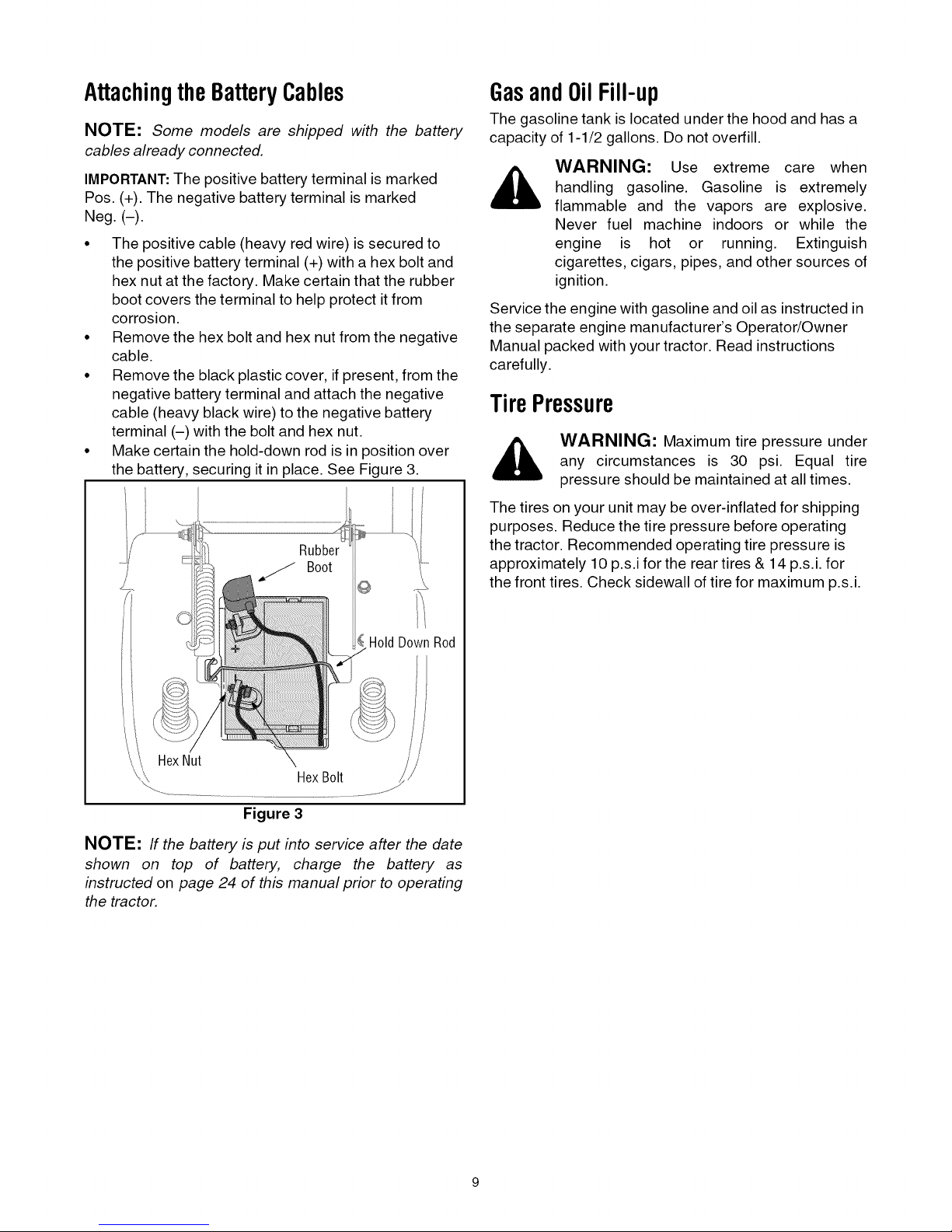
AttachingtheBatteryCables
NOTE: Some models are shipped with the battery
cables already connected.
IMPORTANT:The positive battery terminal is marked
Pos. (+). The negative battery terminal is marked
Neg. (-).
The positive cable (heavy red wire) is secured to
the positive battery terminal (+) with a hex bolt and
hex nut at the factory. Make certain that the rubber
boot covers the terminal to help protect itfrom
corrosion.
Remove the hex bolt and hex nut from the negative
cable.
Remove the black plastic cover, if present, from the
negative battery terminal and attach the negative
cable (heavy black wire) to the negative battery
terminal (-) with the bolt and hex nut.
Make certain the hold-down rod is in position over
the battery, securing it in place. See Figure 3.
GasandOilFill-up
The gasoline tank is located under the hood and has a
capacity of 1-1/2 gallons. Do not overfill.
WARNING: Use extreme care when
handling gasoline. Gasoline is extremely
flammable and the vapors are explosive.
Never fuel machine indoors or while the
engine is hot or running. Extinguish
cigarettes, cigars, pipes, and other sources of
ignition.
Service the engine with gasoline and oil as instructed in
the separate engine manufacturer's Operator/Owner
Manual packed with your tractor. Read instructions
carefully.
TirePressure
_. WARNING: Maximum tire pressure under
The tires on your unit may be over-inflated for shipping
purposes. Reduce the tire pressure before operating
the tractor. Recommended operating tire pressure is
approximately 10 p.s.i for the rear tires & 14 p.s.i, for
the front tires. Check sidewall of tire for maximum p.s.i.
any circumstances is 30 psi. Equal tire
pressure should be maintained at all times.
wn Rod
HexNut
HexBolt
Figure 3
NOTE: If the battery is put into service after the date
shown on top of battery, charge the battery as
instructed on page 24 of this manual prior to operating
the tractor.
Page 10
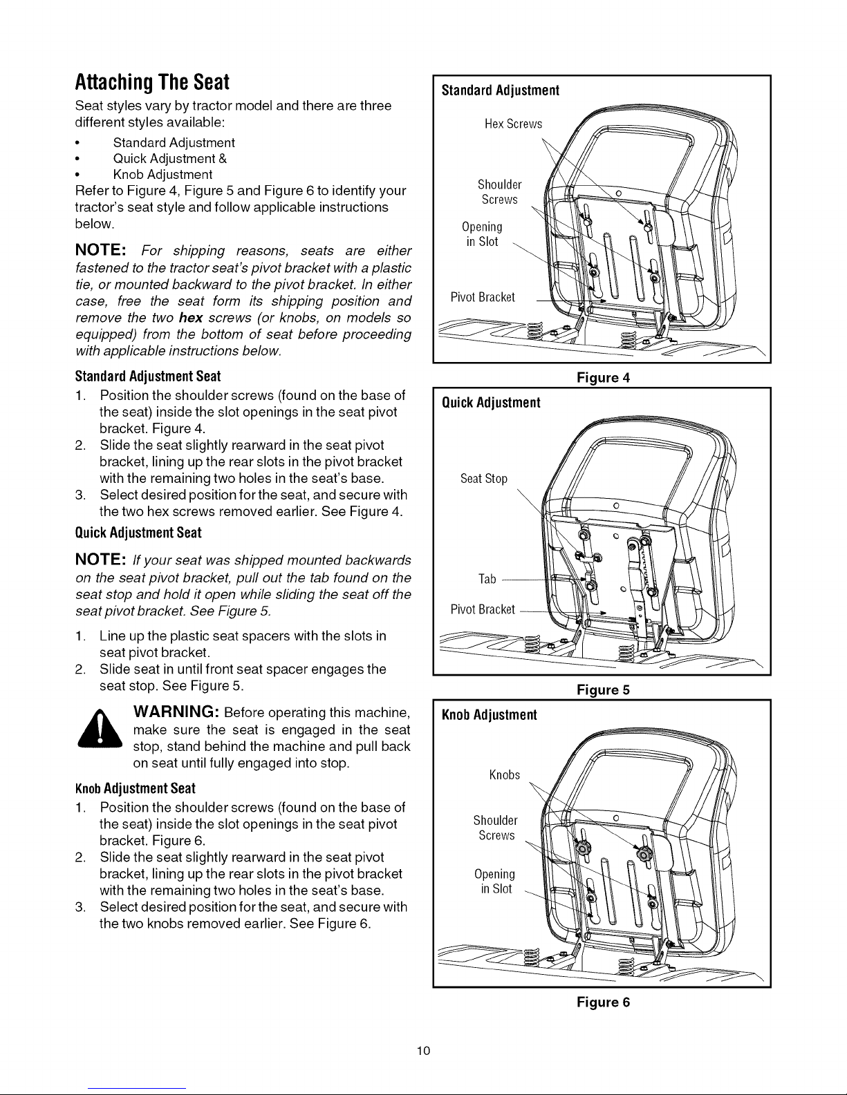
AttachingTheSeat
Seat styles vary by tractor model and there are three
different styles available:
• Standard Adjustment
• Quick Adjustment &
• Knob Adjustment
Refer to Figure 4, Figure 5 and Figure 6 to identify your
tractor's seat style and follow applicable instructions
below.
NOTE: For shipping reasons, seats are either
fastened to the tractor seat's pivot bracket with a plastic
tie, or mounted backward to the pivot bracket. In either
case, free the seat form its shipping position and
remove the two hex screws (or knobs, on models so
equipped) from the bottom of seat before proceeding
with applicable instructions below.
Standard Adjustment
HexScrews
Shoulder
Screws
Opening
in SI0t
Pivot Bracket
Standard AdjustmentSeat
1. Position the shoulder screws (found on the base of
the seat) inside the slot openings in the seat pivot
bracket. Figure 4.
2. Slide the seat slightly rearward in the seat pivot
bracket, lining up the rear slots in the pivot bracket
with the remaining two holes in the seat's base.
3. Select desired position for the seat, and secure with
the two hex screws removed earlier. See Figure 4.
QuickAdjustmentSeat
NOTE: Ifyour seat was shipped mounted backwards
on the seat pivot bracket, pull out the tab found on the
seat stop and hold # open while sliding the seat off the
seat pivot bracket. See Figure 5.
1. Line up the plastic seat spacers with the slots in
seat pivot bracket.
2. Slide seat in until front seat spacer engages the
seat stop. See Figure 5.
WARNING: Before operating this machine,
make sure the seat is engaged in the seat
stop, stand behind the machine and pull back
on seat until fully engaged into stop.
KnobAdjustmentSeat
1. Position the shoulder screws (found on the base of
the seat) inside the slot openings in the seat pivot
bracket. Figure 6.
2. Slide the seat slightly rearward in the seat pivot
bracket, lining up the rear slots in the pivot bracket
with the remaining two holes in the seat's base.
3. Select desired position for the seat, and secure with
the two knobs removed earlier. See Figure 6.
Figure 4
QuickAdjustment
SeatStop
\
Tab --
Pivot Bracket --
Figure 5
KnobAdjustment
Knobs
Shoulder
Screws
Opening
inSlot
Figure 6
lO
Page 11

SECTION4: KNOWYOURLAWNTRACTOR
E
A
F
B
C
G
D
/
H
Figure 7
A Parking Brake Lever E Throttle Control Lever
B brake Pedal F Ignition Switch Module
C Speed Control Lever G Deck Lift Lever
D Choke Control (on models so equipped) H PTO (Blade Engage) Lever
NOTE: Any reference in this manual to the RIGHT or LEFT side of the tractor is observed from operator's position.
11
Page 12

ThrottleControlLever
The throttle control lever is located on the right side of
the tractor's dash panel. This lever controls the speed
of the engine and, on most models, when pushed all the
way forward, the choke control also. When set in a
given position, the throttle will maintain a uniform
engine speed. See Figure 8.
CHOKE
FAST
- EE
EE
ParkingBrakeLever
To set the parking brake, fully
depress the brake pedal. Move the
parking brake lever all the way down
and into the ON position. Release the
brake pedal to allow the parking
brake to engage.
To release the parking brake,
depress the brake pedal and move
the parking brake lever into the OFF
position. Release the brake pedal.
NOTE: The parking brake must be
set if the operator leaves the seat with
the engine running or the engine will
automatically shut off.
OFF
PARK
BRAKE
SLOW
Figure 8
IMPORTANT:When operating the tractor with the cutting
deck engaged, be certain that the throttle lever is
always in the FAST (rabbit) position.
SLOW _'_
ChokeControl
On most models, moving the
throttle lever all the way forward
activates the engine's choke
control. On other models, the
choke control can be found on
the left side of the dash panel and
is activated by pulling the knob
outward. Activating the choke control closes the choke
plate on the carburetor and aids instarting the engine.
Refer to StartingTheEngineon page 15 of this manual for
detailed starting instructions.
BrakePedal
The brake pedal is located on the left side of the lawn
tractor, along the running board. Depress the brake
pedal part way down to slow the tractor's ground speed.
Depress the pedal all the way down to engage the disc
brake and bring the tractor to a complete stop.
DeckLiftLever
Found on your tractor's right fender,
the deck lift lever is used to change
the height of the cutting deck. To use,
move the lever to the left, then place
in the notch best suited for your
application.
PTO(BladeEngage)Lever
Found on the tractor's right fender,
the PTO (blade engage) lever is used
to engage power to the cutting deck
or other (separately available)
attachments. To operate, move the
lever all the way forward. Moving the
lever all the way rearward into the
PTO OFF position disengages power
to the cutting deck/attachment.
NOTE: The PTO (blade engage)
lever must be in the disengaged
(PTO OFF) position when starting the
engine.
ON
O
ol
z
t2
-4
O
W
m
Z
C)
m4
!
O
NOTE: The brake pedal must be depressed to start
the engine. Refer to SafetyInterlockSwitcheson page 14.
"11
12
Page 13

SpeedControlLever
The speed control lever, located on the left fender,
allows you to regulate the travel direction and ground
speed of the lawn tractor. To use, release the parking
brake and move the speed control lever forward (to
travel forward) or rearward (to travel in reverse). The
further forward or rearward that the lever is moved, the
faster the tractor will travel.
IgnitionSwitchModule
WARNING: Never leave a running machine
unattended. Always disengage PTO, move
shift lever into neutral position, set parking
brake, stop engine and remove key to prevent
unintended starting.
To start the engine, insert the key into the ignition
switch and turn clockwise to the START position.
Release the key into the NORMAL MOWING MODE
position once the engine has fired.
To stop the engine, turn the ignition key
counterclockwise to the STOP position. See Figure 9.
Normal
MowingMode
Stop
Position
Start
Position
Place the speed control lever in the Cutting Speed, or
slower, position when mowing.
IMPORTANT:Do NOT attempt to change the direction of
travel when the tractor is in motion. Serious damage to
the tractor's transmission could result. Always bring the
tractor to a complete stop before moving the speed
control lever from forward to reverse or vice versa.
IMPORTANT:Always set the parking brake when
leaving the tractor unattended.
Figure 9
IMPORTANT:Prior to operating the tractor, refer to both
SafetyInterlockSwitcheson page 14 and StartingTheEngine
on page 15 of this manual for detailed instructions
regarding the Ignition Switch Module and operating the
tractor in REVERSE CAUTION MODE.
13
Page 14

SECTION5: OPERATINGYOURLAWNTRACTOR
SafetyInterlockSwitches
This tractor is equipped with a safety interlock system
for the protection of the operator. If the interlock system
should ever malfunction, do not operate the tractor.
Contact an authorized MTD service dealer.
• The safety interlock system prevents the engine
from cranking or starting unless the parking brake is
engaged, and the PTO (Blade Engage) lever is in
the disengaged (OFF) position.
• The engine will automatically shut off if the operator
leaves the seat before engaging the parking brake.
• The engine will automatically shut off if the operator
leaves the tractor's seat with the PTO (Blade
Engage) lever in the engaged (ON) position,
regardless of whether the parking brake is
engaged.
• The engine will automatically shut off if the operator
engages the PTO with the parking brake ON.
• With the ignition key in the NORMAL MOWING
position, the engine will automatically shut off ifthe
PTO (Blade Engage) lever is moved into the
engaged (ON) position with the shift lever in
Reverse.
interlock system is malfunctioning. This
WARNING: Do not operate the tractor ifthe
system was designed for your safety and
protection.
ReverseCautionMode
WARNING: Use extreme caution while
operating the tractor in the REVERSE
CAUTION MODE. Always look down and
behind before and while backing. Do not
operate the tractor when children or others
are around. Stop the tractor immediately if
someone enters the area.
The REVERSE CAUTION MODE position of the key
switch module allows the tractor to be operated in
reverse with the blades (PTO) engaged.
IMPORTANT: Mowing in reverse is not recommended.
To use the REVERSE CAUTION MODE:
IMPORTANT:The operator MUST be seated in the
tractor seat.
,
Start the engine (Refer to Startingthe Enginepage 15
of this Operator's Manual for detailed instructions).
2.
Turn the key from the NORMAL MOWING
(Green) position to the REVERSE CAUTION
MODE (Yellow) position of the key switch module.
See Figure 10.
3. Depress the REVERSE PUSH BUTTON (Orange,
Triangular Button) at the top, right corner of the key
switch module. The red indicator light at the top, left
corner of the key switch module will be ON while
activated. See Figure 10.
4. Once activated (indicator light ON), the tractor can
be driven in reverse with the cutting blades (PTO)
engaged.
5. Always look down and behind before and while
backing to make sure no children are around.
6. After resuming forward motion, return the key to the
NORMAL MOWING position.
IMPORTANT:The REVERSE CAUTION MODE will
remain activated until:
a,
The key is placed in either the NORMAL
MOWING position or STOP position.
b.
The operator engages the parking brake by
fully depressing the brake pedal and holding
it down while gently pushing the parking
brake button inward.
Reverse
indicator
Light
Stop
Position
Figure 10
PushButton
Reverse
- CautionMode
Position
Start
Position
EngagingtheParkingBrake
To engage the parking brake:
• Fully depress the brake pedal and hold it down with
you r foot.
• Move the parking brake lever all the way down and
into the ON position.
• Release the brake pedal to allow the parking brake
to engage.
To release the parking brake:
• Depress the brake pedal and move the parking
brake lever out of the ON position and into the OFF
position.
14
Page 15

WARNING
AVOIDSERIOUSINJURYORDEATH
• GO UP AND DOWN SLOPES, NOT ACROSS.
• AVOID SUDDEN TURNS.
• DO NOT OPERATE THE UNIT WHERE IT COULD SLIP OR TIR
• IF MACHINE STOPS GOING UPHILL, STOP BLADE(S) AND BACK
DOWNHILL SLOWLY.
• DO NOT MOW WHEN CHILDREN OR OTHERS ARE AROUND.
• NEVER CARRY CHILDREN, EVEN WITH BLADES OFR
• LOOK DOWN AND BEHIND BEFORE AND WHILE BACKING.
• KEEP SAFETY DEVICES (GUARDS, SHIELDS, AND SWITCHES) IN
PLACE AND WORKING.
• REMOVE OBJECTS THAT COULD BE THROWN BY THE BLADE(S).
• KNOW LOCATION AND FUNCTION OF ALL CONTROLS.
• BE SURE BLADE(S) AND ENGINE ARE STOPPED BEFORE PLAC-
ING HANDS OR FEET NEAR BLADE(S).
• BEFORE LEAVING OPERATOR'S POSITION, DISENGAGE
BLADE(S), PLACE THE SHIFT LEVER IN NEUTRAL, ENGAGE
BRAKE LOCK, SHUT ENGINE OFF AND REMOVE KEY.
READOPERATOR'SMANUAL
IMPORTANT:Do NOT hold the key in the START
position for longer than ten seconds at a time. Doing so
may cause damage to your engine's electric starter.
• After the engine starts, deactivate the choke control
and place the throttle control in the FAST position.
NOTE: Do NOT leave the throttle control in the
CHOKE position while operating the tractor. Doing so
will result in a "rich" fuel mixture and cause the engine
to run poorly.
StoppingtheEngine
WARNING: If you strike a foreign object,
stop the engine, disconnect the spark plug
wire(s) and ground against the engine.
Thoroughly inspect the machine for any
damage. Repair the damage before restarting
and operating
SettingtheCuttingHeight
Select the height position of the cutting deck by placing
the deck lift lever in any of the five different cutting
height notches on the right side of the fender. Then
adjust the deck wheels, if so equipped, so that they are
between 1A-inch and _/2-inchabove the ground when the
tractor is on a smooth, flat surface such as a driveway.
_, ARNING: Keep hands and feet away
from the discharge opening of the cutting
deck.
NOTE: On models so equipped, the deck wheels are
an anti-scalp feature of the deck and are not designed
to support the weight of the cutting deck.
Refer to LevelingtheDeckon page 18 of this manual for
more detailed instructions regarding various deck
adjustments.
StartingtheEngine
interlock system is malfunctioning. This
WARNING: Do not operate the tractor ifthe
system was designed for your safety and
protection.
NOTE:
manual for Gasoline and Oil till-up instructions.
• Insert the tractor key into the ignition switch.
• Place the PTO (Blade Engage) lever) in the
• Engage the tractor's parking brake.
• Activate the choke control.
• Turn the ignition key clockwise to the START
Refer to the TRACTORSET-UPon page 8 of this
disengaged (OFF) position.
position. After the engine starts, release the key. It
will return to the NORMAL MOWING position.
• If the blades are engaged, place the PTO (Blade
Engage) lever in the disengaged (OFF) position.
• Turn the ignition key counterclockwise to the STOP
position.
• Remove the key from the ignition switch to prevent
unintended starting.
DrivingTheLawnTractor
,_ WARNING: Always look down and behind
• Move
NOTE: Always operate the tractor with the throttle
control lever in the FAST (rabbit) position for the most
efficient use of the cutting deck or other (separately
available) attachments.
IMPORTANT:Do NOT attempt to change the direction of
travel when the tractor is in motion. Always bring the
tractor to a complete stop before moving the speed
control lever from forward to reverse or vice versa.
Failure to do so could result in serious damage to your
tractor's transmission.
before and while traveling in reverse to avoid
a back-over accident.
WARNING: Before leaving the operator's
position. Always place the PTO (blade
engage) lever in the disengaged (PTO OFF)
position, place speed control lever in neutral,
set parking brake, stop engine and remove
key to prevent unintended starting.
throttle control lever to full throttle.
Release the parking brake by depressing the brake
pedal.
Position the speed control lever in desired position.
The further forward or rearward that the lever is
moved, the faster the tractor will travel.
15
Page 16

IMPORTANT: First-time operators should use slower
speeds. Become completely familiar with the tractor's
operation and controls before operating the tractor in at
higher speed.
• The lawn tractor is brought to a stop by depressing
the brake pedal.
• Set the parking brake by fully depressing the brake
pedal and keeping it depressed while placing the
parking brake lever in the ON position. Release the
brake pedal to allow the parking brake to engage.
position for any reason, disengage the
WARNING: Before leaving the operator's
blades, place the speed control lever in
neutral, engage the parking brake, shut
engine off and remove the key.
IMPORTANT:When stopping the tractor for any reason
while on a grass surface, always
• Place the speed control lever inN (neutral),
• Engage the parking brake,
• Shut engine off and remove the key.
Doing so will minimize the possibility of having your
lawn "browned" by hot exhaust from your tractor's
running engine.
DrivingOnSlopes
Refer to the SLOPEGAUGEon page 7 to help determine
slopes where you may operate the tractor safely.
_, ARNING: Do not mow on inclines with a
• Mow up and down slopes, NEVER across.
• Exercise extreme caution when changing direction
• Watch for holes, ruts, bumps, rocks, or other
• Avoid turns when driving on a slope. Ifa turn must
• Avoid stopping when driving up a slope. If it is
slope in excess of 15 degrees (a rise of
approximately 2-1/2 feet every 10 feet). The
tractor could overturn and cause serious
injury.
on slopes.
hidden objects. Uneven terrain could overturn the
machine. Tall grass can hide obstacles.
be made, turn down the slope. Turning up a slope
greatly increases the chance of a roll over.
necessary to stop while driving up a slope, start up
smoothly and carefully to reduce the possibility of
flipping the tractor over backward.
Usingthe DeckLiftLever
To raise the cutting deck, move the deck lift lever to the
left, then place it in the notch best suited for your
application. Refer to SettingTheCuttingHeightearlier in
this section.
EngagingtheBlades
Engaging the PTO (Blade Engage) transfers power to
the cutting deck or other (separately available)
attachments. To engage the blades, proceed as
follows:
• Move the throttle control lever to the FAST (rabbit)
position.
• Grasp the PTO (Blade Engage) lever and position it
all the way forward into the engaged (ON) position.
• Keep the throttle lever in the FAST (rabbit) position
for the most efficient use of the cutting deck or other
(separately available) attachments
IMPORTANT:The engine will automatically shut off if the
PTO is engaged with the shift lever in position for
reverse travel with the ignition key in the NORMAL
MOWING position. Refer to SafetyInterlockSwitcheson
page 14.
Mowing
WARNING: To help avoid blade contact or
a thrown object injury, keep bystanders,
helpers, children and pets at least 75 feet
from the machine while it is in operation. Stop
machine if anyone enters the area.
The following information will be helpful when using the
cutting deck with your tractor.
WARNING: Plan your mowing pattern to
avoid discharge of materials toward roads,
sidewalks, bystanders and the like. Also,
avoid discharging material against a wall or
obstruction which may cause discharged
material to ricochet back toward the operator.
• Never mow at the tractor's fastest ground speed.
Maintaining a slower ground speed will result in an
optimal cut.
• For best results it is recommended that the first two
laps be cut with the discharge thrown towards the
center. After the first two laps, reverse the direction
to throw the discharge to the outside for the
balance of cutting. This will give a better
appearance to the lawn.
• Do not cut the grass too short. Short grass invites
weed growth and yellows quickly in dry weather.
• Mowing should always be done with the throttle
control lever to the FAST (rabbit) position.
• Under heavier conditions it may be necessary to go
back over the area a second time to get a clean cut.
• Do NOT attempt to mow heavy brush and weeds
and extremely tall grass. Your tractor is designed to
mow lawns, NOT clear brush.
• Keep the blades sharp and replace the blades
when worn. Refer to CuttingBladeson page 24 of this
manual for proper blade sharpening instructions.
16
Page 17

Mulching
Some, NOT ALL, models come equipped with a mulch
kit which incorporates special blades, already standard
on your tractor, in a process of recirculating grass
clippings repeatedly beneath the cutting deck. The
ultra-fine clippings are then forced back into the lawn
where they act as a natural fertilizer. Observe the
following points for the best results when mulching.
• Never attempt to mulch if the lawn is damp. Wet
grass tends to stick to the underside of the cutting
deck preventing proper mulching of the clippings.
• Do NOT attempt to mulch more than 1/3 the total
height of the grass or approximately 1-1/2 inches.
Doing so will cause the clippings to clump up
beneath the deck and not be mulched effectively.
• Maintain a slow ground speed to allow the grass
clippings more time to effectively be mulched.
• Always position the throttle control lever in the
FAST (rabbit) position and allow itto remain there
while mowing. Failing to keep the engine at full
throttle places strain on the tractor's engine and
does not allow the blades to properly mulch grass.
MovingTheTractorManually
Your tractor's transmission is equipped with a
hydrostatic relief valve for occasions when it is
necessary to move the tractor manually. Activating this
valve forces the fluid in the transmission to bypass its
normal route, allowing the rear tires to "freewheel." To
engage the hydrostatic relief valve, proceed as follows:
• Locate the hydrostatic bypass rod inthe rear of the
tractor. See Figure 12.
• Pull the hydrostatic bypass rod outward, then down
and to the left, to lock it in place.
NOTE: Do NOT remove the discharge chute when
operating the mower with the mulch kit installed,
To operate the cutting deck without mulching, on
models so equipped, simply remove the mulch plug by
unthreading the plastic wing nut which secures itto the
cutting deck. This will allow the clippings to discharge
out the side. See Figure 11.
CarriageScrew
@
PlasticWing Nut Mulch Plug
Figure 12
NOTE: The transmission will NOT engage when the
hydrostatic bypass rod is pulled out. Return the rod to
its normal position prior to operating the tractor.
IMPORTANT:Never attempt to move the tractor
manually without first engaging the hydrostatic relief
valve. Doing so will result in serious damage to the
tractor's transmission.
Headlights
On some models, the lamps are ON whenever the
tractor's engine is running. On other models, the lamps
are ON whenever the ignition key is moved out of the
STOP position.
On all models, the lamps turn OFF when the ignition
key is moved to the STOP position.
Figure 11
17
Page 18

SECTION6: MAKINGADJUSTMENTS
_, WARNING: Never attempt to make any
LevelingtheDeck
NOTE: Check the tractor's tire pressure before
performing any deck leveling adjustments. Refer to
Tires on page 23 for information regarding tire pressure.
FrontToRear
The front of the cutting deck is supported by a stabilizer
bar that can adjusted to level the deck from front to rear.
The front of the deck should be between 1/4-inch and
3/8-inch lower than the rear of the deck. Adjust if
necessary as follows:
• With the tractor parked on a firm, level surface,
• Measure the distance from the front of the blade tip
• The first measurement taken should be between
• Locate the jam nut and lock nut found on the front
adjustments while the engine is running,
except where specified in the operator's
manual.
place the deck lift lever in the top notch (highest
position) and rotate the blade nearest the discharge
chute so that it is parallel with the tractor.
to the ground and the rear of the blade tip to the
ground.
1/4" and 3/8" less than the second measurement.
Determine the approximate distance necessary for
proper adjustment and proceed, if necessary.
side of the stabilizer bracket. See Figure 14. After
loosening the jam nut:
Tighten the lock nut to raise the front of the deck;
Loosen the lock nut to lower the front of the deck.
• Retighten the jam nut loosened earlier after proper
adjustment is achieved.
Sideto Side
If the cutting deck appears to be mowing unevenly, a
side to side adjustment can be performed. Adjust if
necessary as follows:
• With the tractor parked on a firm, level surface,
place the deck lift lever inthe top notch (highest
position) and rotate both blades so that they are
perpendicular with the tractor.
• Measure the distance from the outside of the left
blade tip to the ground and the distance from the
outside of the right blade tip to the ground. Both
measurements taken should be equal. If they're
not, proceed to the next step.
• Loosen, but do NOT remove, the hex screw on the
left deck hanger bracket. See Figure 14.
Adjustment Gear
.........J
Figure 13
Figure 14
• Balance the deck by using a wrench to turn the
adjustment gear (found immediately behind the hex
cap screw just loosened) clockwise/up or
counterclockwise/down.
• The deck is properly balanced when both blade tip
measurements taken earlier are equal.
• Retighten the hex cap screw on the left deck
hanger bracket when proper adjustment is
achieved.
18
Page 19
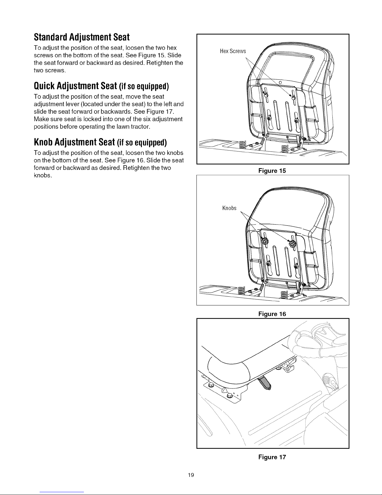
StandardAdjustmentSeat
To adjust the position of the seat, loosen the two hex
screws on the bottom of the seat. See Figure 15. Slide
the seat forward or backward as desired. Retighten the
two screws.
QuickAdjustmentSeat(ifsoequipped)
To adjust the position of the seat, move the seat
adjustment lever (located under the seat) to the leftand
slide the seat forward or backwards. See Figure 17.
Make sure seat is locked into one of the six adjustment
positions before operating the lawn tractor.
KnobAdjustmentSeat(ifsoequipped)
To adjust the position of the seat, loosen the two knobs
on the bottom of the seat. See Figure 16. Slide the seat
forward or backward as desired. Retighten the two
knobs.
HexScrews
Figure 15
Knobs
Figure 16
\
\
Figure 17
19
Page 20

ParkingBrakeAdjustment
WARNING: Never attempt to adjust the
brakes while the engine is running. Always
disengage PTO, move speed control lever
into neutral position, stop engine and remove
key to prevent unintended starting.
If the tractor does not come to a complete stop when
the brake pedal is completely depressed, or if the
tractor's rear wheels can roll with the parking brake
applied (and the hydrostatic bypass rod pulled out), the
brake is in need of adjustment. The brake disc can be
found on the right side of the transmission in the rear of
the tractor. Adjust if necessary as follows:
NOTE: A replacement cotter pin (part no. 714-0111)
is needed to complete this adjustment. Have one on
hand before proceeding.
• Looking at the transmission from the right side of
the tractor, locate the compression spring and
brake disc. See Figure 18.
CrownNut
DragLinkAdjustment
If the tractor turns tighter in one direction than the other,
or if either the drag link and ball joint are being replaced
due to damage or wear, the drag link may need to be
adjusted. To do so, proceed as follows:
• Place the steering wheel in position for straight-
ahead travel.
• Remove the lock nut which secures the ball joint to
the steering arm. See Figure 19.
DragLink BallJoint
BrakeDisc
NOTE: Rear, right wheel not shown for clarity
Figure 18
• Carefully remove the cotter pin from the crown nut
on the right side of the brake assembly.
• Using a feeler gauge, check the gap between the
brake disc and the brake puck. Proper gap is .011"
• Tighten the crown nut until the proper gap is
achieved.
• Insert the replacement cotter pin into the crown nut.
LockNut
Figure 19
• Lift the ball joint out of the steering arm and re-
position both front tires for straight-ahead travel.
• Loosen the jam nut (See Figure 19) and thread the
ball joint either inward or outward until it aligns with
the hole in the steering arm.
• Confirm that both the steering wheel and the front
tires are still positioned for straight-ahead travel
before reinserting the ball joint into the steering arm
and securing it with the lock nut removed earlier.
• Re-tighten the jam nut loosened earlier.
20
Page 21

SECTION7: MAINTAININGYOURLAWNTRACTOR
WARNING: Before performing any
maintenance or repairs, disengage PTO,
move shift lever into neutral position, set
parking brake, stop engine and remove key to
prevent unintended starting.
Engine
Refer to the engine manufacturer's Operator/Owner
Manual for engine maintenance instructions.
Check engine oil level before each use as instructedin
the engine manufacturer's Operator/Owner Manual
packed with your unit. Follow the instructions
carefully.
Changing EngineOil
NOTE: Depending on the engine model found on your
tractor, it may be necessary to remove the tractor's side
panel in order to replace the oil filter (if so equipped).
Changing EngineOil
For draining oil from the engine's crankcase of select
model tractors, a plastic oil drain sleeve is packed with
this Operator's Manual. To drain the oil, proceed as
follows:
Unscrew the oil fill cap and remove the dipstick
from the oil fill tube.
Snap the small end of oil drain sleeve onto the oil
sump. See Figure 20.
• Service the oil filter (if so equipped) as instructed
in the separate engine manufacturer's Operator/
Owner Manual packed with your unit.
Perform the above steps in the opposite order after oil
has finished draining.
• Refill the engine with new motor oil.
IMPORTANT:Refer to the engine manufacturer's
Operator/Owner Manual packed with your unit for
information regarding the quantity and proper weight of
motor oil.
Air Cleaner
Service the pre-cleaner, if so equipped, and cartridge/
air cleaner element as instructed in the engine
manufacturer's Operator/Owner Manual packed with
your unit.
SparkPlug(s)
The spark plug(s) should be cleaned and the gap reset
once a season. Spark plug replacement is
recommended at the start of each mowing season.
Refer to the engine manufacturer's Operator/Owner
Manual for correct plug type and gap specifications.
Lubrication
WARNING: Before lubricating, repairing, or
inspecting, always disengage PTO, move
shift lever into neutral position, set parking
brake, stop engine and remove key to prevent
unintended starting.
Figure 20
Remove drain plug and drain oil into a suitable
container with a capacity of no less than 64 oz.
Engine
Lubricate the engine with motor oil as instructed inthe
engine manufacturer's Owner Manual packed with your
unit.
PivotPoints& Linkage
Lubricate all the pivot points on the drive system,
parking brake and lift linkage at least once a season
with light oil.
RearWheels
The rear wheels should be removed from the axles
once a season. Lubricate the axles and the rims well
with an all-purpose grease before re-installing them.
Front Axles
Each end of the tractor's front pivot bar may be
equipped with a grease fitting. Lubricate with a grease
gun after every 25 hours of tractor operation.
21
Page 22
CleaningtheEngineAndDeck
Any fuel or oil spilled on the machine should be wiped
off promptly. Do NOT allow debris to accumulate
around the cooling fins of the engine or on any other
part of the machine.
IMPORTANT:The use of a pressure washer to clean
your tractor is NOT recommended. It may cause
damage to electrical components, spindles, pulleys,
bearings or the engine.
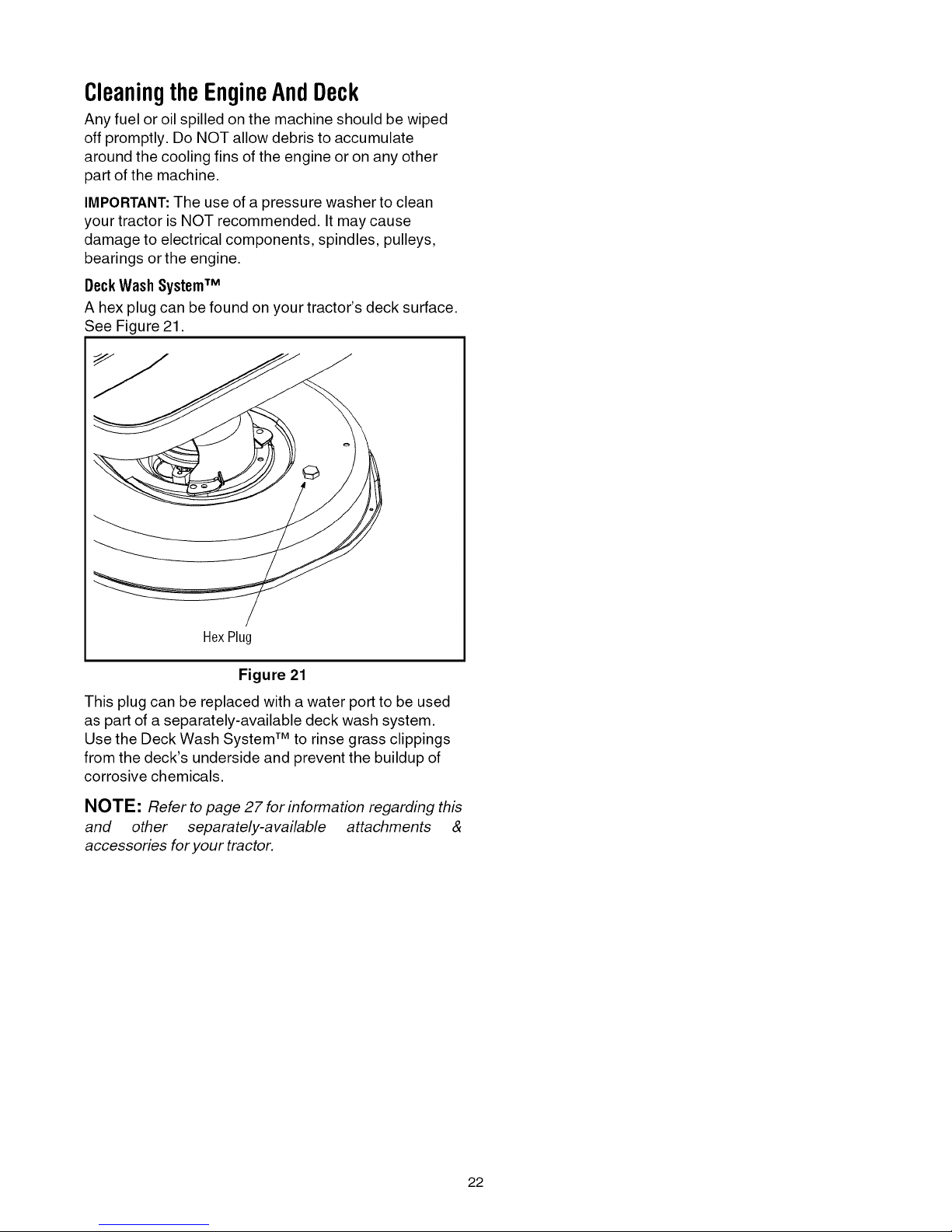
DeckWash SystemTM
A hex plug can be found on your tractor's deck surface.
See Figure 21.
HexPlug
Figure 21
This plug can be replaced with a water port to be used
as part of a separately-available deck wash system.
Use the Deck Wash System TM to rinse grass clippings
from the deck's underside and prevent the buildup of
corrosive chemicals.
NOTE: Refer to page 27 for information regarding this
and other separately-available attachments &
accessories for your tractor.
22
Page 23
SECTION8: SERVICE
CuttingDeckRemoval
NOTE: Models equipped with a 38-inch deck have
one deck idler pulley. Models equipped with a 42-inch
deck have two deck idler pulleys.
To remove the cutting deck, proceed as follows:
• Place the PTO (Blade Engage) lever in the
disengaged (OFF) position.
• Engage the parking brake.
• Lower the deck by moving the deck lift lever into the
bottom notch on the right fender.
• Remove the belt from around the tractor's engine
pulley and idler pulley(s). Refer to Changingthe Beck
Belton page 26 for detailed instructions.
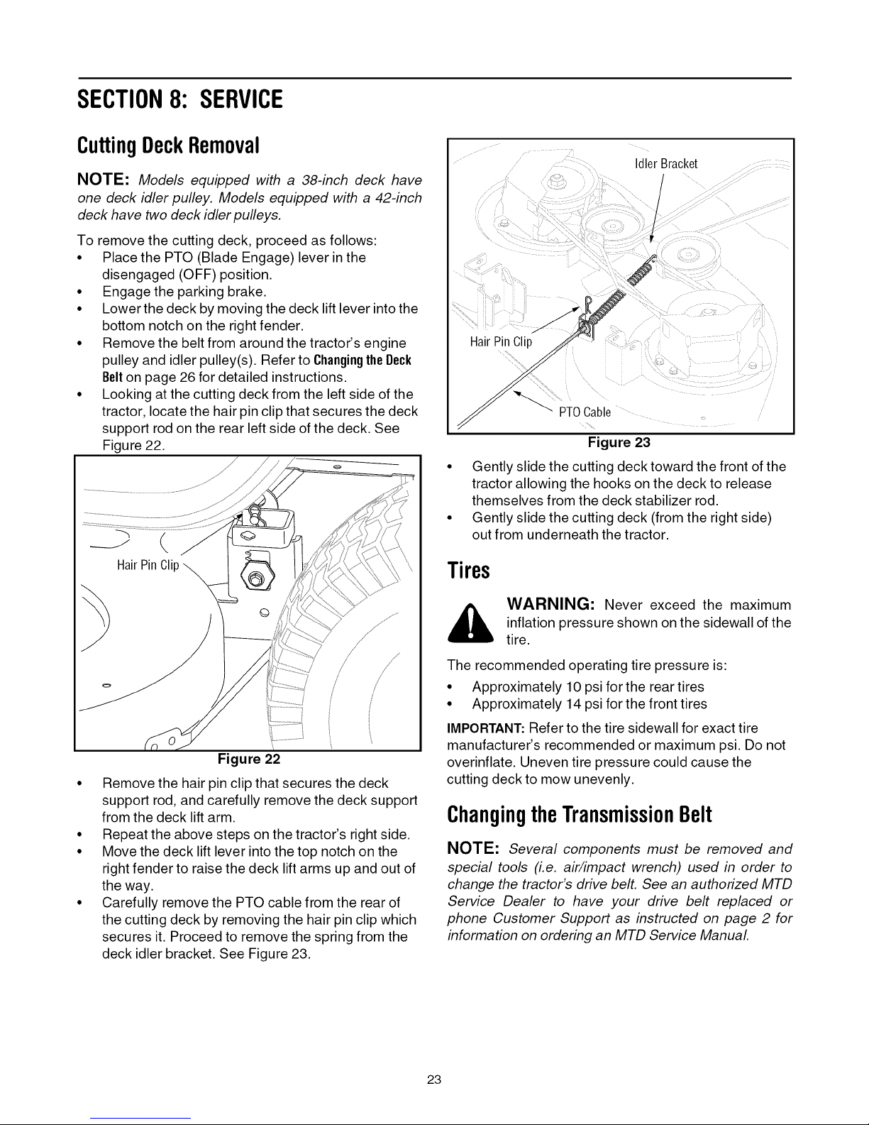
• Looking at the cutting deck from the left side of the
tractor, locate the hair pin clip that secures the deck
support rod on the rear left side of the deck. See
Figure 22.
IdlerBracket
f
t
HairPinClip
'- PTOCable
Figure 23
• Gently slide the cutting deck toward the front of the
tractor allowing the hooks on the deck to release
themselves from the deck stabilizer rod.
• Gently slide the cutting deck (from the right side)
out from underneath the tractor.
/
/
Figure 22
• Remove the hair pin clip that secures the deck
support rod, and carefully remove the deck support
from the deck lift arm.
• Repeat the above steps on the tractor's right side.
• Move the deck lift lever into the top notch on the
right fender to raise the deck lift arms up and out of
the way.
• Carefully remove the PTO cable from the rear of
the cutting deck by removing the hair pin clip which
secures it. Proceed to remove the spring from the
deck idler bracket. See Figure 23.
Tires
_, WARNING: Never exceed the maximum
The recommended operating tire pressure is:
• Approximately 10 psi for the rear tires
• Approximately 14 psi for the front tires
IMPORTANT:Refer to the tire sidewall for exact tire
manufacturer's recommended or maximum psi. Do not
overinflate. Uneven tire pressure could cause the
cutting deck to mow unevenly.
inflation pressure shown on the sidewall of the
tire.
ChangingtheTransmissionBelt
NOTE: Several components must be removed and
special tools (i.e. air/impact wrench) used in order to
change the tractor's drive belt. See an authorized MTD
Service Dealer to have your drive belt replaced or
phone Customer Support as instructed on page 2 for
information on ordering an MTD Service Manual
23
Page 24
Battery
The battery is sealed and is maintenance-free. Acid
levels cannot be checked.
• Always keep the battery cables and terminals clean
and free of corrosive build-up.
• After cleaning the battery and terminals, apply a
light coat of petroleum jelly or grease to both
terminals.
• Always keep the rubber boot positioned over the
positive terminal to prevent shorting.
IMPORTANT:If removing the battery for any reason,
disconnect the NEGATIVE (Black) wire from it's
terminal first, followed by the POSITIVE (Red) wire.
When re-installing the battery, always connect the
POSITIVE (Red) wire its terminal first, followed by the
NEGATIVE (Black) wire. Be certain that the wires are
connected to the correct terminals; reversing them
could change the polarity and result in damage to your
engine's alternating system.
Charging
If the tractor has not been put into use for an extended
period of time, charge the battery with an automotive-
type 12-volt charger for a minimum of one hour at six
amps.
Cleaning
Clean the battery by removing it from the tractor and
washing with a baking soda and water solution. If
necessary, scrape the battery terminals with a wire
brush to remove deposits. Coat terminals and exposed
wiring with grease or petroleum jelly to prevent
corrosion.
BatteryFailures
Some common causes for battery failure are:
• freezing • undercharging
• overcharging • corroded connections
These failures are NOT covered by your tractor's
warranty.
Fuse
One 20 AMP fuse is installed in your tractor's wiring
harness to protect the tractor's electrical system from
damage caused by excessive amperage.
If the electrical system does not function, or your
tractor's engine will not crank, first check to be certain
that the fuse has not blown. It can be found under the
hood mounted behind the dash panel on the right side.
_, ARNING: Always use a fuse with the
same amperage capacity for replacement.
WARNING: Batteries give off an explosive
gas while charging. Charge battery in a well
ventilated area and keep away from an open
flame or pilot light as on a water heater, space
heater, furnace, clothes dryer or other gas
appliances.
JumpStarting
_ WARNING: When removing or installing
IMPORTANT: Never jump your tractor's dead battery
with the battery of a running vehicle.
• Connect end of one jumper cable to the positive
• Connect the other jumper cable to the negative
the battery, follow these instructions to
prevent the screwdriver from shorting against
the frame.
terminal of the good battery, then the other end to
the positive terminal of the dead battery.
terminal of the good battery, then to the frame of
the unit with the dead battery.
could cause sparking, and the gas in either
WARNING: Failure to use this procedure
battery could explode.
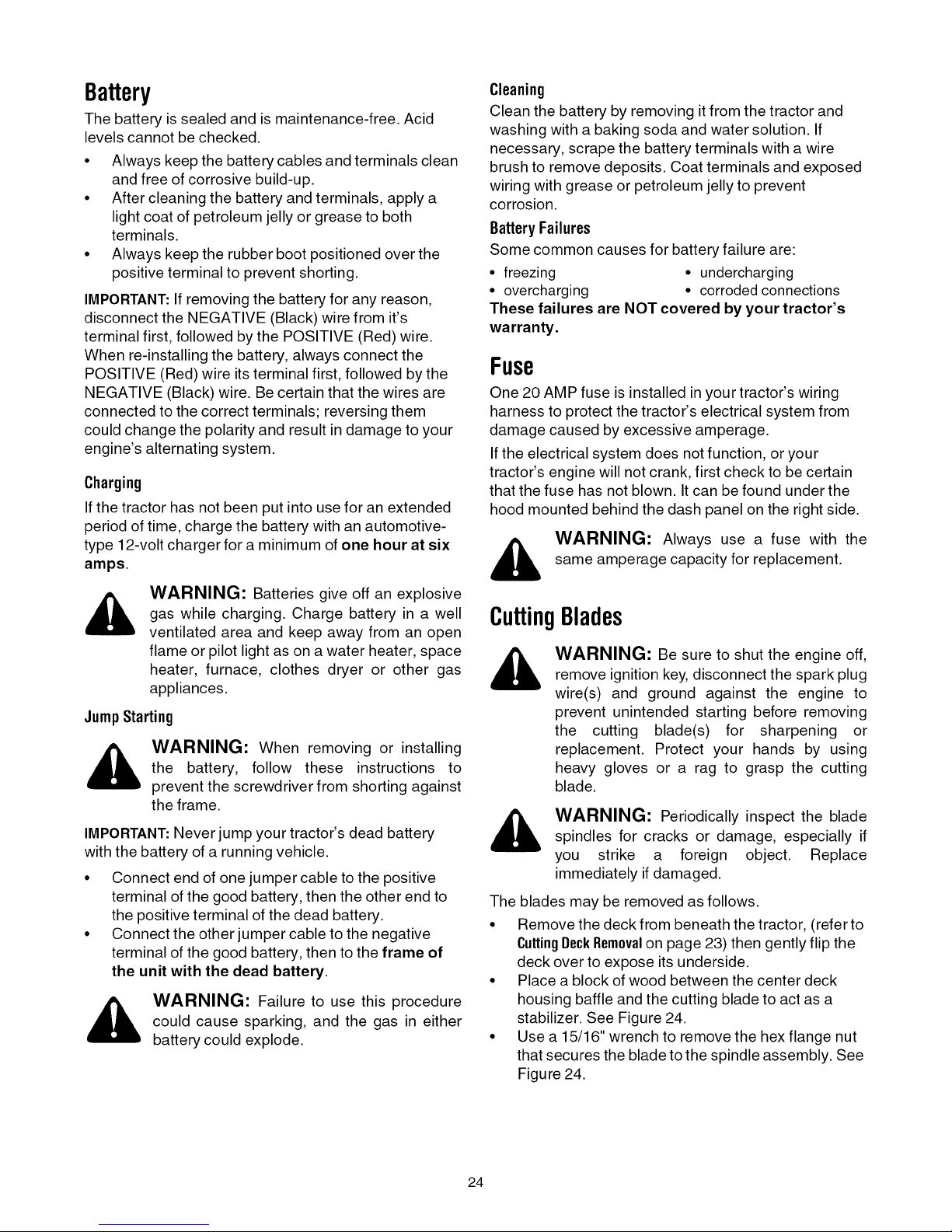
CuttingBlades
WARNING: Be sure to shut the engine off,
remove ignition key, disconnect the spark plug
wire(s) and ground against the engine to
prevent unintended starting before removing
the cutting blade(s) for sharpening or
replacement. Protect your hands by using
heavy gloves or a rag to grasp the cutting
blade.
_, ARNING: Periodically inspect the bladespindles for cracks or damage, especially if
you strike a foreign object. Replace
immediately if damaged.
The blades may be removed as follows.
• Remove the deck from beneath the tractor, (refer to
CuttingDeckRemovalon page 23) then gently flip the
deck over to expose its underside.
• Place a block of wood between the center deck
housing baffle and the cutting blade to act as a
stabilizer. See Figure 24.
• Use a 15/16" wrench to remove the hex flange nut
that secures the blade to the spindle assembly. See
Figure 24.
24
Page 25
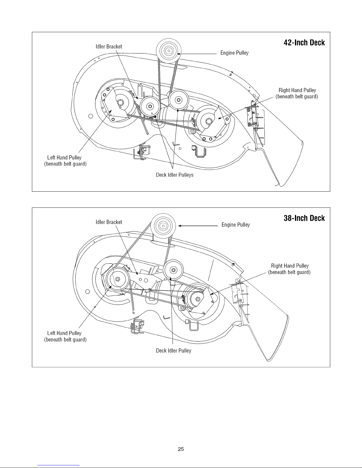
Left Hand Pulley
(beneathbelt guard)
IdlerBracket 42-Inch Deck
EnginePulley
Right Hand Pulley
(beneathbelt guard)
©
Deck Idler Pulleys
Left Hand Pulley
(beneathbelt guard)
Idler Bracket
Deck Idler Pulley
/
38-InchDeck
EnginePulley
Right Hand Pulley
(beneathbelt guard)
25
Page 26

HexFlangeNut
SpindleAssembly
Figure 24
To properly sharpen the cutting blades, remove
equal amounts of metal from both ends of the
blades along the cutting edges, parallel to the
trailing edge, at a 25 °to 30°angle. See Figure 25.
BladeSeparation
/
/
WornBladeEdge
Wind Wing
IMPORTANT:Use a torque wrench to tighten the blade
spindle hex flange nut to between 70 foot-pounds and
90 foot-po unds.
ChangingtheDeckBelt
WARNING: Be sure to shut the engine off,
remove ignition key, disconnect the spark
plug wire(s) and ground against the engine to
prevent unintended starting before removing
the belt(s).
All belts on your tractor are subject to wear and should
be replaced if any signs of wear are present.
IMPORTANT:TheV-belts found on your tractor are
specially designed to engage and disengage safely. A
substitute (non-OEM) V-belt can be dangerous by not
disengaging completely. For a proper working machine,
use factory approved belts.
To change or replace the deck belt on your tractor,
proceed as follows:
• Lower the deck by moving the deck lift lever into the
bottom notch on the right fender.
• Remove the belt guards by removing the self-
tapping screws that fasten them to the deck.
• Remove the belt keeper rod from around the
engine pulley.
• Insert a 3/8"-drive ratchet wrench (set to loosen)
into the square hole found in the idler bracket on
the left side of the deck's surface. See Figure 26.
BeltGuard
/
SharpenEdgeEvenly
Figure 25
IMPORTANT:Ifthe cutting edge of the blade has already
been sharpened to within 5/8" of the wind wing radius,
or if any metal separation is present, replace the blades
with new ones. See Figure 25.
It is important that each cutting blade edge be ground
equally to maintain proper blade balance.
A poorly balanced blade will cause excessive vibration
and may cause damage to the tractor and result in
personal injury. The blade can be tested by balancing it
on a round shaft screwdriver. Grind metal from the
heavy side until it balances evenly.
When replacing the blade, be sure to install the blade
with the side of the blade marked "Bottom"facing the
ground when the mower is in the operating position.
Idler Bracket_
Figure 26
• Grasp the ratchet's handle and pivot it toward the
front of the tractor to relieve tension on the belt.
• With belt tension relieved, carefully remove the
belt from around the left-hand spindle pulley.
26
Page 27

SECTION9: OFF-SEASONSTORAGE
Clean and lubricate the tractor as instructed in Section7:
MAINTAININGYOURLAWNTRACTORon page 21 of this
manual before storing for an extended period.
WARNING: Drain fuel only into an
approved container outdoors, away from an
open flame. Allow engine to cool. Extinguish
cigarettes, cigars, pipes, and other sources of
ignition prior to draining fuel.
Follow the instructions in the Service, Storage &
Specifications section of the engine manufacturer's
Operator/Owner Manual for proper engine care prior to
storing your tractor.
WARNING: Never store the machine or
fuel container indoors where there is an open
flame, spark or pilot light such as on water
heater, furnace, clothes dryer or other gas
appliance.
SECTION10: ATTACHMENTS& ACCESSORIES
The following attachments and accessories are compatible for 700-Series Lawn Tractors. See the retailer from
which you purchased your tractor, an authorized MTD Service Dealer or phone 1-800-800-7310 for information
regarding price and availability.
NOTE: Model Series 700 Lawn Tractors are NOT designed for use with any type of ground-engaging attachments
(e.g. tiller or plow). Use of this type of equipment WILL void the tractor's warranty.
MODEL
OEM-190-116
0EM-190-672
OEM-190-180
OEM-190-183
OEM-190-184
0EM-190-218
OEM-190-658
OEM-190-032
OEM-190-833
490-900-0024
490-900-0025
38- and 42-inch Deck Mulch Kit
Grille Guard (mounts on front of tractor)
Twin Bagger Grass Collector
Deck Wheel Kit
Dethatcher
Rear Wheel Weights
Tire Chains
42-inch Two-stage Snow Thrower
46-inch Front Dozer Blade
Deluxe Tractor Sunshade
Deck Wash Kit
DESCRIPTION
* Not compatible with tractors equipped with a Grass Collector
27
Page 28

SECTION11:TROUBLESHOOTING
Trouble
Engine fails to start
Engine runs erratic
Engine overheats Engine oil level low.
Engine hesitates at high RPM Spark plug(s) gap too close.
Idles poorly Spark plug(s) fouled, faulty or gap too
Excessive vibration
Mower will not mulch grass
Uneven cut Deck not balanced properly.
Possible Cause(s)
PTO engaged.
Parking brake not engaged.
Spark plug wire(s) disconnected.
Throttle control lever not in correct
starting position.
Choke not activated
Fuel tank empty, or stale fuel.
Blocked fuel line.
Faulty spark plug.
Engine flooded.
Unit running with CHOKE applied.
Spark plug wire(s) loose.
Blocked fuel line or stale fuel.
Vent in gas cap plugged.
Water or dirt in fuel system.
Dirty air cleaner.
Air flow restricted.
wide.
Dirty air cleaner.
Cutting blade loose or unbalanced.
Damaged or bent cutting blade.
Engine speed too low.
Wet grass.
Excessively high grass.
Dull blade.
Dull blade.
Uneven tire pressure.
Corrective Action
Place PTO lever in disengaged (OFF) position.
Engage parking brake.
Connect wire(s) to spark plug(s).
Place throttle control in FAST position or CHOKE posi-
tion, if present.
Place the throttle control in CHOKE position or pull the
CHOKE knob outward.
Fill tank with clean, fresh (less than 30 days old) gas.
Clean fuel line or replace fuel filter, if so equipped.
Clean, adjust gap or replace plug.
Crank engine with throttle in FAST position.
Move the throttle control out of the CHOKE position or
push the CHOKE knob inward.
Connect and tighten spark plug wire(s).
Clean fuel line; fill tank with clean, fresh (less than 30
days old) gasoline. Replace fuel filter, ifso equipped.
Clear vent or replace cap if damaged.
Drain fuel tank. Refill with clean, fresh (less than 30
days old) gasoline.
Replace air cleaner cartridge/element or clean pre-
cleaner, if so equipped.
Fill crankcase with proper capacity and weight of oil.
Clean grass clippings and debris from around the
engine's cooling fins and blower housing.
Remove spark plug(s) and reset the gap.
Replace spark plug(s). Set plug(s) gap.
Replace air cleaner cartridge/element or clean pre-
cleaner, if so equipped.
Tighten blade and spindle. Balance blade.
Replace blade.
Place throttle control in FAST (rabbit) position.
Do not mow when grass is wet; wait until later to cut.
Mow once at a high cutting height, then mow again at
desired height or make a narrower cutting swath.
Sharpen or replace blade.
Perform side-to-side deck adjustment.
Sharpen or replace blade.
Check tire pressure in all four tires.
28
Page 29

NOTES
29
Page 30

NOTES
30
Page 31

NOTES
31
Page 32

MANUFACTURER'S LIMITED WARRANTY FOR:
YaRD.MaNTM
®
The limited warranty set forth below is given by MTD LLC with
respect to new merchandise purchased and used in the
United States, its possessions and territories.
"MTD" warrants this product against defects in material and
workmanship for a period of two (2) years commencing on the
date of original purchase and will, at its option, repair or
replace, free of charge, any part found to be defective in
materials or workmanship. This limited warranty shall only
apply if this product has been operated and maintained in
accordance with the Operator's Manual furnished with the
product, and has not been subject to misuse, abuse,
commercial use, neglect, accident, improper maintenance,
alteration, vandalism, theft, fire, water, or damage because of
other peril or natural disaster. Damage resulting from the
installation or use of any part, accessory or attachment not
approved by MTD for use with the product(s) covered by this
manual will void your warranty as to any resulting damage.
Normal wear parts are warranted to be free from defects in
material and workmanship for a period of thirty (30) days from
the date of purchase. Normal wear parts include, but are not
limited to items such as: batteries, belts, blades, blade
adapters, grass bags, rider deck wheels, seats, snow thrower
skid shoes, shave plates, auger spiral rubber and tires.
HOW TO OBTAIN SERVICE: Warranty service is available,
WITH PROOF OF PURCHASE, through your local authorized
service dealer. To locate the dealer in your area, check your
Yellow Pages, or contact MTD LLC at P.O. Box 361131,
Cleveland, Ohio 44136-0019, or call 1-800-800-7310 or log
on to our Web site at www.mtdproducts.com.
This limited warranty does not provide coverage inthe
following cases:
a,
The engine or component parts thereof. These items
may carry a separate manufacturer's warranty. Refer
to applicable manufacturer's warranty for terms and
conditions.
b,
Log splitter pumps, valves, and cylinders have a
separate one year warranty.
C.
Routine maintenance items such as lubricants, filters,
blade sharpening, tune-ups, brake adjustments, clutch
adjustments, deck adjustments, and normal
deterioration of the exterior finish due to use or
exposure.
d,
Service completed by someone other than an
authorized service dealer.
e,
MTD does not extend any warranty for products sold or
exported outside of the United States, its possessions
and territories, except those sold through MTD's
authorized channels of export distribution.
f,
Replacement parts that are not genuine MTD parts.
Transportation charges and service calls.
g.
No implied warranty, including any implied warranty of
merchantability of fitness for a particular purpose,
applies after the applicable period of express written
warranty above as to the parts as identified. No other
express warranty, whether written or oral, except as
mentioned above, given by any person or entity,
including a dealer or retailer, with respect to any product,
shall bind MTD. During the period of the warranty, the
exclusive remedy is repair or replacement of the product
as set forth above.
The provisions as set forth in this warranty provide the
sole and exclusive remedy arising from the sale. MTD
shall not be liable for incidental or consequential loss or
damage including, without limitation, expenses incurred
for substitute or replacement lawn care services or for
rental expenses to temporarily replace a warranted
product.
Some states do not allow the exclusion or limitation of
incidental or consequential damages, or limitations on how
long an implied warranty lasts, so the above exclusions or
limitations may not apply to you.
In no event shall recovery of any kind be greater than the
amount of the purchase price of the product sold. Alteration
of safety features of the product shall void this warranty.
You assume the risk and liability for loss, damage, or injury to
you and your property and/or to others and their property
arising out of the misuse or inability to use the product.
This limited warranty shall not extend to anyone other than the
original purchaser orto the person for whom it was purchased
as a gift.
HOW STATE LAW RELATES TO THIS WARRANTY: This
limited warranty gives you specific legal rights, and you may
also have other rights which vary from state to state.
IMPORTANT:Owner must present Original Proof of
Purchase to obtain warranty coverage.
MTD LLC, P.O.BOX361131CLEVELAND,OHIO44136-0019;Phone:1-800-800-7310
 Loading...