

Page 1

Safety • Assembly • Operation • Adjustment • Maintenance • Troubleshooting • Warranty
-ro AL
Transmatic Lawn Tractor- Model 771
READ SAFETY RULES AND iNSTRUCTiONS CAREFULLY BEFORE OPERATION
Warning: Thisunitis equippedwithaninternalcombustionengineandshouldnot beusedon ornearanyunimprovedforest-covered,brush-
coveredor grass-coveredlandunlesstheengine'sexhaustsystemisequippedwithasparkarrestermeetingapplicablelocalor statelaws(if any).
If a sparkarresterisused,it shouldbemaintainedineffectiveworkingorderby theoperator.IntheStateofCaliforniatheaboveis requiredbylaw
(Section4442ofthe CaliforniaPublicResourcesCode).Otherstatesmayhavesimilarlaws.Federallawsapplyonfederallands.A sparkarrester
forthe mufflerisavailablethroughyournearestengineauthorizedservicedealeror contacttheservicedepartment,RO.Box361131Cleveland,
Ohio44136-0019.
PRINTEDIN U.S.A.
MTD LLC, P.O. BOX 361131 CLEVELAND, OHIO 44136-0019
iMPORTANT
FORMNO.769-02171A
01/06/2006
Page 2
This Operator's Manual is an important part of your new lawn tractor, it will help you assemble,
prepare and maintain the unit for best performance. Please read and understand what it says.
Table of Contents
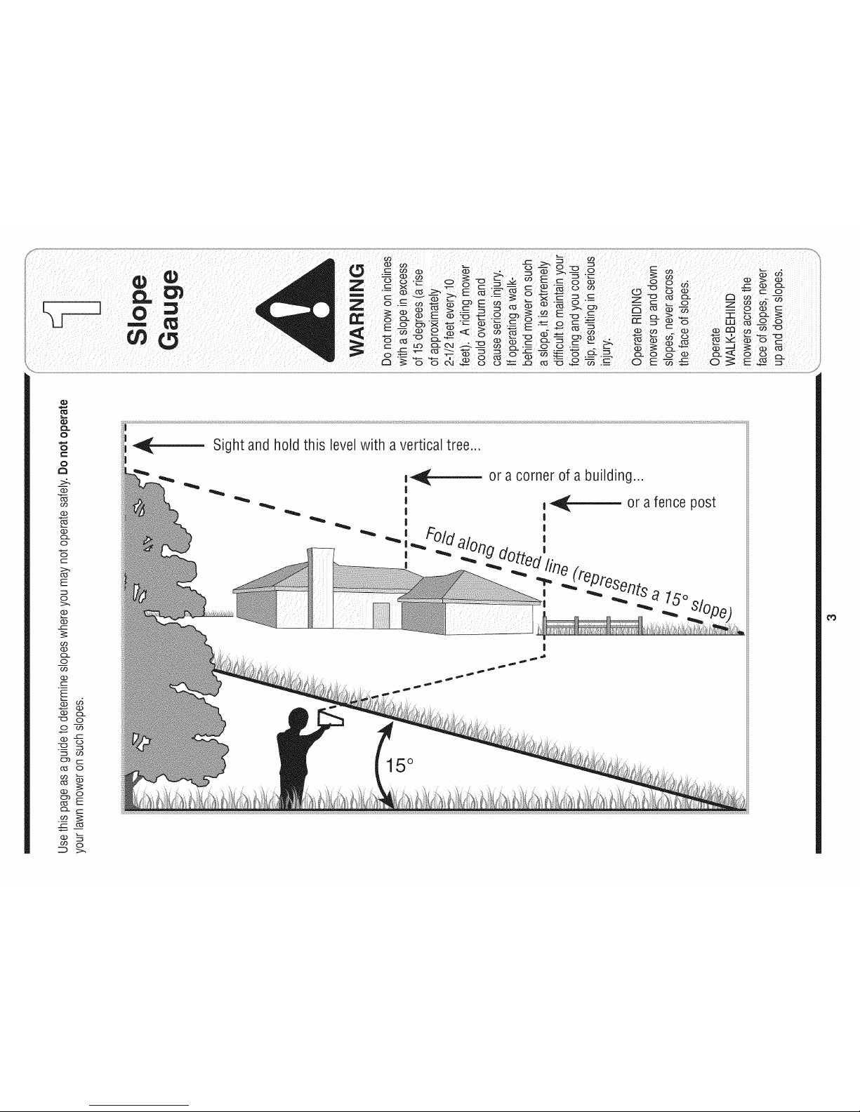
Slope Gauge ....................................................... 3
Safe Operation Practices ................................... 4
Setting UpYour Lawn Tractor ............................ 8
Operating Your Lawn Tractor ........................... 12
Adjusting Your Lawn Tractor ............................ 20
Finding and Recording IVlodel Number
BEFOREYOU STARTASSEMBLING
YOURNEW EQUIPMENT,
please locatethe modelplate on the equipmentand copythe
informationto the sample model plate providedto the right.
Youcan locatethe modelplate by lookingbeneathethe seat.
Thisinformationwillbe necessaryto use themanufacturer's
website and/or obtainassistancefromthe CustomerSupport
Departmentoran authorizedservice dealer.
Maintaining Your Lawn Tractor ........................ 22
Off-Season Storage / Attachments ................. 28
Safety Labels .................................................... 29
Trouble Shooting .............................................. 30
Warranty .............................................. Back Page
P. O. BOX 361131
o CLEVELAND,OH 44136
www.yardman.com 330-220-4683
800-800-731 O
Customer Support
Please do NOTreturn the unit to the retailer from which it was
purchased, without first contacting Customer Support.
Ifyou have difficultyassemblingthis productorhave any questions regardingthe controls, operation,or maintenanceof this
unit,you can seek help from the experts.Choosefrom the options below:
1. Visit yardman.com. Click on the Service& Support
menuoption.
2. Phonea Customer Support Representative at 1 (800)
800-7310.
3. Theengine manufacturerisresponsible for allengine-
relatedissueswith regardsto performance,power-rating,
specifications,warrantyand service. Pleasereferto the
enginemanufacturer'sOwner's/Operator's Manual,packed
separatelywithyour unit,for moreinformation.
2
Page 3
O
o
1=
o
>:.
(13
O3
(13
(13
O-
O
O
(--
O5
E
O
(13
(13
o3
(13
O-
O
o3
(13
E
(]3
(13
o
(13
C5
('5
O3
O5
(13
t"b
(13
O9
o5
(13
O-
O
O3
-5
O3
O
O
E
Sightandholdthis levelwith a verticaltree...
also
I
15°
Page 4
WARNING: EngineExhaust,some of itsconstituents,andcertain vehicle compo-
nentscontain or emitchemicals knownto State of Californiato causecancer and
birth defectsor otherreproductiveharm.
DANGER: This machinewas builtto beoperatedaccording to the rulesfor safe operationin this
manual.As with any type of power equipment,carelessnessor erroronthe part ofthe operatorcan
result inseriousinjury.This machine iscapableof amputatinghands andfeet andthrowing objects.
Failureto observethe followingsafety instructionscould resultin serious injury ordeath.
Practices
WARNING
Thissymbol points
out importantsafety
instructionswhich, if
notfollowed, could
endangerthe personal
safetyand/or property
ofyourself and others.
Readand follow all
I instructionsinthis man-
ualbeforeattemptingto
operatethis machine.
tFailureto complywith
hese instructionsmay
resultin personalinjury.
When youseethis
symbol.
HEED iTS WARNING
Your
Responsibility
Restrictthe use
of this power machine
to personswho read,
understand
andfollow thewarnings
and instructions
in this manual
Children
1. Tragicaccidentscanoccurifthe operatoris not
alertto thepresenceof children.Childrenareoften
attractedto themachineandthemowingactivity.
Theydo notunderstandthe dangers.Neverassume
thatchildrenwillremainwhereyoulastsawthem.
a. Keepchildrenoutofthe mowingareaandin
watchfulcareof a responsibleadultother than
theoperator.
b. Bealertandturnmachineoff ifa childenters
thearea.
c. Beforeandwhilebacking,lookbehindand
downfor smallchildren.
d. Nevercarrychildren,evenwiththeblade(s)
shutoff.Theymayfalloffandbeseriously
injuredor interferewithsafemachineoperation.
e. Useextremecarewhenapproachingblind
corners,doorways,shrubs,treesorother
objectsthatmayblockyourvisionofachild
whomayrunintothemachine.
f. To avoid back-overaccidents, always
disengagethe cuttingblade(s) before
shiftingintoReverse.ifequipped,the
"Reverse CautionMode"shouldnotbe
usedwhenchildrenor others arearound.
g. Keepchildrenawayfromhotor running
engines.Theycansufferburnsfroma hot
muffler.
h. Removekeywhenmachineisunattendedto
preventunauthorizedoperation.
2. Neverallowchildrenunder14yearsoldto operate
themachine.Children14yearsoldandovershould
readand understandtheoperationinstructionsand
safetyrulesinthis manualandshouldbetrainedand
supervisedbya parent.
Operation
Safe Handling of Gasoline:
1. Toavoid personalinjuryor propertydamageuse
extremecareinhandlinggasoline.Gasolineis
extremely flammableand the vapors areexplo-
sive. Seriouspersonalinjurycanoccurwhengasoline
isspilledonyourselforyourclotheswhichcan ignite.
Washyourskinandchangeclothesimmediately.
a. Useonlyanapprovedgasolinecontainer.
b. Neverfillcontainersinsideavehicleorona
truckor trailerbedwitha plasticliner.Always
placecontainerson thegroundawayfrom
yourvehiclebeforefilling.
c. Whenpractical,removegas-powered
equipmentfromthetruckor trailerand refuelit
ontheground.Ifthis isnotpossible,then
refuelsuchequipmenton a trailerwitha
portablecontainer,ratherthanfroma gasoline
dispensernozzle.
d. Keepthenozzlein contactwiththe rimof
thefueltankor containeropeningatall
timesuntilfuelingiscomplete.Donot usea
nozzlelock-opendevice.
e. Extinguishallcigarettes,cigars,pipesand
othersourcesofignition.
f. Neverfuel machineindoors.
g. Neverremovegascap oraddfuelwhilethe
engineishot or running.Allowenginetocool
atleasttwominutesbeforerefueling.
h. Neveroverfill fueltank.Filltankto nomore
than1/2inchbelowbottomoffillerneckto
allowspacefor fuelexpansion.
i. Replacegasolinecapandtightensecurely.
j. If gasolineisspilled,wipeit off theengine
andequipment.Moveunittoanotherarea.
Wait5 minutesbeforestartingtheengine.
k. Toreducefirehazards,keepmachinefreeof
grass,leaves,orotherdebris build-up.Clean
upoil orfuelspillageand removeanyfuel
soakeddebris.
I. Neverstorethe machineorfuelcontainer
insidewherethereis anopenflame,spark
orpilotlightason a waterheater,space
heater,furnace,clothesdryerorother gas
appliances.
m. Allowa machineto coolatleastfiveminutes
beforestoring.
4
Page 5
GeneralOperation:
1. Read,understand,andfollowall instructionsonthe
machineandin themanual(s)beforeattemptingto
assembleandoperate.Keepthismanualina safe
placefor futureandregularreferenceandforordering
replacementparts.
2. Befamiliarwithallcontrolsandtheirproperoperation.
Knowhowtostopthe machineanddisengagethem
quickly.
3, Neverallowchildrenunder14yearsold to operate
this machine.Children14yearsoldandovershould
readandunderstandtheoperationinstructionsand
safetyrulesinthis manualandshouldbetrainedand
supervisedbya parent.
4. Neverallowadultstooperatethis machinewithout
properinstruction.
5. To helpavoidbladecontactorathrownobjectinjury,
keepbystanders,helpers,childrenand petsat least
75feet fromthemachinewhileitis inoperation.Stop
machineifanyoneentersthearea.
6. Thoroughlyinspecttheareawheretheequipmentis to
be used.Removeall stones,sticks,wire,bones,toys,
andotherforeignobjectswhichcouldbe pickedup
andthrownbythe blade(s).Thrownobjectscancause
seriouspersonalinjury.
7. Planyourmowingpatterntoavoiddischargeof
materialtowardroads,sidewalks,bystandersandthe
like.Also,avoiddischargingmaterialagainstawall or
obstructionwhichmaycausedischargedmaterialto
ricochetbacktowardtheoperator.
8. Alwayswearsafetyglassesor safetygogglesduring
operationandwhile performingan adjustmentor
repairtoprotectyoureyes.Thrownobjectswhich
ricochetcancauseseriousinjuryto theeyes.
9. Wearsturdy,rough-soledworkshoesandclose-fitting
slacksandshirts.Loosefittingclothesandjewelry
canbecaughtinmovableparts.Neveroperatethis
machinein barefeetor sandals.
10.Beawareofthe mowerandattachmentdischarge
directionanddo notpointitat anyone.Donotoperate
themowerwithoutthedischargecoverorentiregrass
catcherin itsproperplace.
11.Donotput handsorfeetnearrotatingpartsor under
thecuttingdeck.Contactwiththe blade(s)can
amputatehandsandfeet.
12.A missingor damageddischargecovercan cause
bladecontactorthrownobjectinjuries.
13.Stoptheblade(s)whencrossinggraveldrives,walks,
or roadsandwhilenotcuttinggrass.
14.Watchfortrafficwhenoperatingnearorcrossing
roadways.Thismachineisnotintendedforuseon
anypublic roadway.
15.Donotoperatethe machinewhileundertheinflu-
enceof alcoholordrugs.
16.Mowonlyin daylightor goodartificiallight.
17.Nevercarrypassengers.
18.Disengageblade(s)beforeshiftingintoreverse.
Backupslowly.Alwayslookdownandbehindbefore
andwhilebackingto avoida back-overaccident.
19.Slowdownbeforeturning.Operatethe machine
smoothly.Avoiderraticoperationandexcessive
speed.
20.Disengageblade(s),setparkingbrake,stopengine
andwaituntilthe blade(s)cometo a completestop
beforeremovinggrasscatcher,emptyinggrass,
uncloggingchute,removinganygrassor debris,or
makinganyadjustments.
21.Neverleavea runningmachineunattended.Always
turnoff blade(s),placetransmissionin neutral,set
parkingbrake,stopengineand removekeybefore
dismounting.
22.Useextracare whenloadingorunloadingthe
machineintoa trailerortruck.Thisunitshouldnot
bedrivenupor downramp(s),becausethe unit
couldtip over,causingseriouspersonalinjury.The
unitmustbepushedmanuallyonramp(s)to loador
unloadproperly.
23.Mufflerandenginebecomehotandcan causea
burn.Do nottouch.
24.Checkoverheadclearancescarefullybeforedriving
underlowhangingtreebranches,wires,dooropen-
ingsetc.,wheretheoperatormaybe struckor pulled
fromthe unit,whichcouldresultinseriousinjury.
25.Disengageallattachmentclutches,depressthe
brakepedalcompletelyandshift intoneutralbefore
attemptingtostartengine.
26.Yourmachineisdesignedto cutnormalresidential
grassofa heightno morethan10".Donotattemptto
mowthroughunusuallytall,dry grass(e.g.,pasture)
or pilesof dryleaves.Drygrassor leavesmay
contacttheengineexhaustand/orbuildup onthe
mowerdeckpresentingapotentialfirehazard.
27.Useonlyaccessoriesandattachmentsapprovedfor
thismachinebythe machinemanufacturer.Read,
understandandfollowall instructionsprovidedwith
theapprovedaccessoryorattachment.
28.Dataindicatesthat operators,age60 yearsand
above,are involvedin a largepercentageofriding
mower-relatedinjuries.Theseoperatorsshould
evaluatetheirabilityto operatethe ridingmower
safelyenoughto protectthemselvesandothersfrom
seriousinjury.
29.Ifsituationsoccurwhicharenot coveredinthis
manual,usecareandgoodjudgment.Contactyour
customerservicerepresentativeforassistance.
........................................................................................
WARNING
Thissymbol points
out importantsafety
instructionswhich, if
notfollowed,could
endangerthe personal
safety and/or property
ofyourselfand others.
Readand followall
instructions inthis man-
ual beforeattemptingto
operatethis machine.
Failureto comply with
these instructionsmay
result inpersonalinjury.
Whenyou seethis
symbol.
HEED ITS WARNING
Your
Responsibility
Restrictthe use
ofthis power machine
to personswho read,
understand
and follow the warnings
and instructions
inthis manual
5
Page 6
Thissymbolpoints
outimportantsafety
instructionswhich,if
notfollowed,could
endangerthepersonal
isafetyand/orproperty
ofyourselfandothers.
Readandfollowall
instructionsinthisman-
ualbeforeattemptingto
Ioperatethismachine.
I Failuretocomplywith
theseinstructionsmay
i resultinpersonalinjury.
Whenyouseethis
symbol.
i HEED ITSWARNING
Slope Operation:
Slopesarea majorfactorrelatedtolossof controland
tip-overaccidentswhichcanresultin severeinjuryor
death.All slopesrequireextracaution.If youcannot
backuptheslopeor ifyoufeeluneasyonit, donotmow
it.
Foryour safety,usetheslopegaugeincludedas partof
thismanualto measureslopesbeforeoperatingthisunit
ona slopedor hillyarea.Iftheslopeisgreaterthan15
degreesasshownon theslopegauge,do notoperate
thisunitonthatareaor seriousinjurycouldresult.
DO:
1. Mowupanddownslopes,notacross.Exercise
extremecautionwhenchangingdirectiononslopes.
2. Watchforholes,ruts,bumps,rocks,orother hidden
objects.Uneventerraincouldoverturnthe machine.
Tallgrasscan hideobstacles.
3. Useslowspeed.Choosealow enoughspeed
settingso thatyouwill nothavetostopor shiftwhile
ontheslope.Tiresmaylosetractiononslopeseven
thoughthebrakesarefunctioningproperly.Always
keepmachineingearwhengoingdownslopesto
takeadvantageof enginebrakingaction.
4. Followthe manufacturer'srecommendationsfor
wheelweightsorcounterweightstoimprovestability.
5. Useextracare withgrasscatchersorotherat-
tachments.Thesecanchangethestabilityof the
machine.
6. Keepall movementon the slopesslowand gradual.
Donot makesuddenchangesinspeedor direction.
Rapidengagementor brakingcouldcausethe front
ofthe machineto liftandrapidlyflipoverbackwards
whichcouldcauseseriousinjury.
7. Avoidstartingorstoppingona slope.Iftireslose
traction,disengagetheblade(s)andproceedslowly
straightdowntheslope.
Do Not:
1. Do notturnon slopesunlessnecessary;then,turn
slowlyandgraduallydownhill,ifpossible.
2. Do notmowneardrop-offs,ditchesor embankments.
Themowercouldsuddenlyturnoverif awheel isover
theedgeof a cliff,ditch,orifan edgecavesin.
3. Do nottrytostabilizethemachineby puttingyourfoot
ontheground.
4. Do notusea grasscatcheronsteepslopes.
5. Do notmowonwetgrass.Reducedtractioncould
causesliding.
6. Do notshiftto neutralandcoastdownhill.Over-speed-
ingmaycausetheoperatortolosecontrolofthe
machineresultingin seriousinjuryordeath.
7. Do nottowheavypullbehindattachments(e.g.loaded
dumpcart, lawnroller,etc.)on slopesgreaterthan
5 degrees.Whengoingdown hill,theextraweight
tendsto pushthetractorandmaycauseyouto loose
control.(e.g.tractormayspeedup, brakingandsteer-
ingabilityarereduced,attachmentmayjack-knifeand
causetractorto overturn).
Towing:
1. Towonlywitha machinethathasahitchdesignedfor
towing.Donotattachtowedequipmentexceptatthe
hitchpoint.
2. Followthe manufacturersrecommendationfor weight
limitsfor towedequipmentandtowingon slopes.
3. Neverallowchildrenorothersin orontowedequip-
ment.
4. Onslopes,theweightof thetowedequipmentmay
causelossoftractionandlossofcontrol.
5. Travelslowlyandallowextradistancetostop.
6. Do notshiftto neutralandcoastdownhill.
Your
i Responsibility
Restrictthe use
of this power machine
to personswho read,
understand
and followthe warnings
and instructions
in this manual
6
Page 7
Service
1. Neverrunanengineindoorsorina poorlyventilated
area.Engineexhaustcontainscarbonmonoxide,an
odorless,anddeadlygas.
2. Beforecleaning,repairing,or inspecting,makecertain
theblade(s)andall movingpartshavestopped.
Disconnectthesparkplugwireandgroundagainstthe
engineto preventunintendedstarting.
3. Periodicallychecktomakesurethebladescometo
completestopwithinapproximately(5) fiveseconds
afteroperatingthebladedisengagementcontrol.Ifthe
bladesdo notstopwithinthethis timeframe,yourunit
shouldbe servicedprofessionallyby anauthorized
MTDServiceDealer.
4. Checkbrakeoperationfrequentlyas itis subjectedto
wearduringnormaloperation.Adjustand serviceas
required.
5. Checktheblade(s)andenginemountingboltsat
frequentintervalsfor propertightness.Also,visually
inspectblade(s)fordamage(e.g.,excessivewear,
bent,cracked). Replacetheblade(s)withtheoriginal
equipmentmanufacturer's(O.E.M.)blade(s)only,
listedinthis manual."Useof partswhichdonot meet
theoriginalequipmentspecificationsmayleadto
improperperformanceandcompromisesafety!"
6. Mowerbladesaresharp.Wrapthe bladeor wear
gloves,anduseextracautionwhenservicingthem.
7. Keepallnuts, bolts,andscrewstightto besurethe
equipmentis insafeworkingcondition.
8. Nevertamperwiththe safetyinterlocksystemor other
safetydevices.Checktheirproperoperationregularly.
9. Afterstrikingaforeignobject,stoptheengine,
disconnectthesparkplugwire(s)andgroundagainst
theengine.Thoroughlyinspectthe machineforany
damage.Repairthedamagebeforestartingand
operating.
10.Neverattempttomakeadjustmentsor repairstothe
machinewhilethe engineisrunning.
11.Grasscatchercomponentsandthe discharge
coveraresubjectto wearanddamagewhichcould
exposemovingpartsor allowobjectstobethrown.
Forsafetyprotection,frequentlycheckcomponents
andreplaceimmediatelywithoriginalequipment
manufacturer's(O.E.M.)partsonly,listedinthis
manual."Useofpartswhichdonotmeettheoriginal
equipmentspecificationsmayleadto improper
performanceandcompromisesafety!"
12.Donotchangetheenginegovernorsettingsor
over-speedthe engine.Thegovernorcontrolsthe
maximumsafeoperatingspeedofthe engine.
13.Maintainor replacesafetyandinstructionlabels,as
necessary.
14.Observeproperdisposallawsandregulationsfor
gas,oil,etc. toprotecttheenvironment.
Thissymbol points
out importantsafety
instructionswhich, if
notfollowed,could
endangerthe personal
safetyand/or property
of yourselfand others.
Readandfollow all
instructionsin this man-
ual beforeattemptingto
operatethis machine.
Failureto complywith
these instructionsmay
result inpersonalinjury.
When yousee this
symbol.
HEED iTS WARNING
Your
Responsibility
Restrictthe use
ofthis power machine
to personswho read.
understand
and followthe warnings
and instructions
in this manual
7
Page 8
Tractor
Use extreme care
whenhandling
gaso nelGasoline
extremely flammable
and the vapors are
explosive: Never fuel
machine indoors
or while the engine
is hotor running,
Extinguish cigarettes,
cigars, pipes,and
othersourcesof
ignitionl
RubberBoot
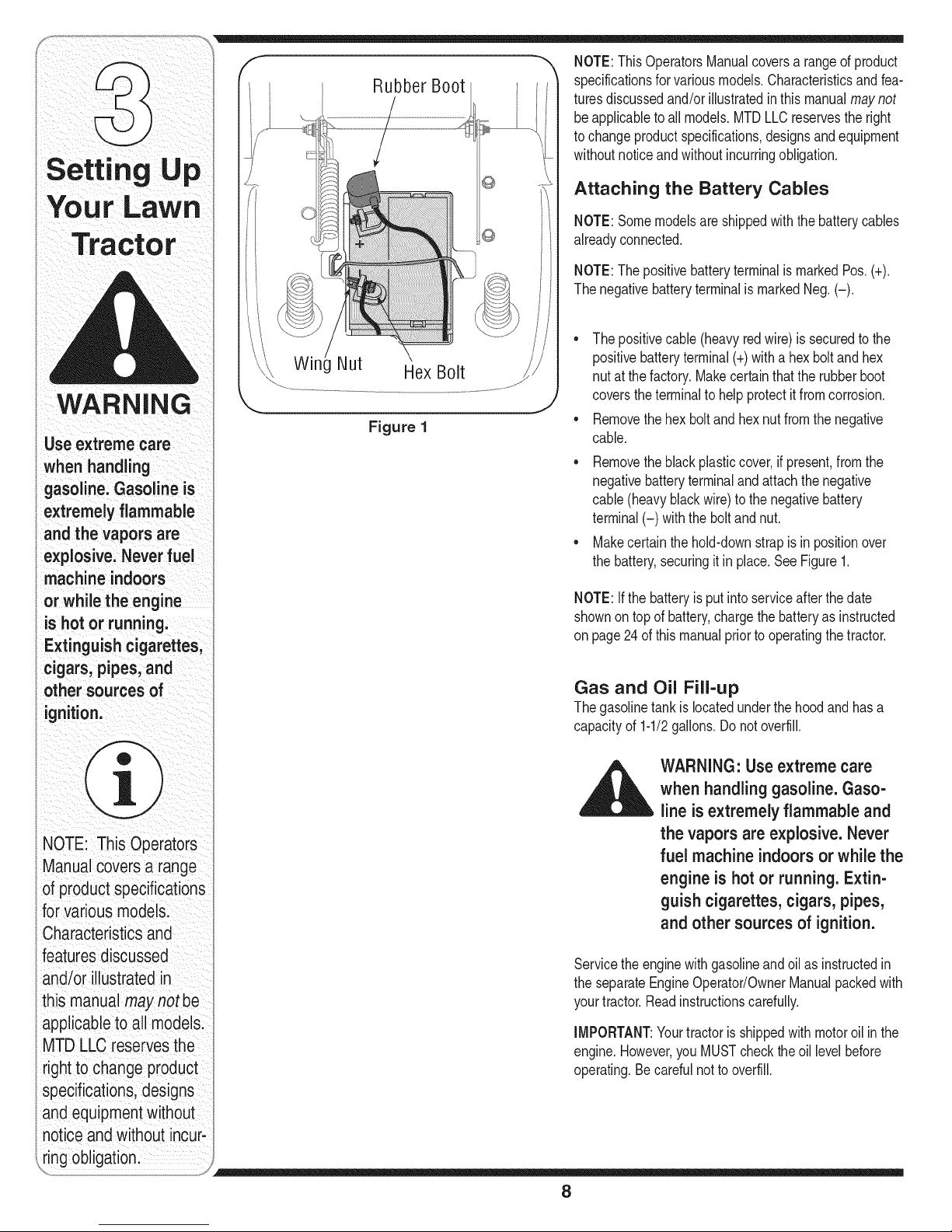
Figure 1
NOTE:ThisOperatorsManualcoversa rangeof product
specificationsfor variousmodels.Characteristicsandfea-
turesdiscussedand/orillustratedinthis manualmaynot
beapplicabletoall models.MTDLLCreservesthe right
tochangeproductspecifications,designsandequipment
withoutnoticeandwithoutincurringobligation.
Attaching the Battery Cables
NOTE:Somemodelsareshippedwiththe batterycables
alreadyconnected.
NOTE:ThepositivebatteryterminalismarkedPos.(+).
Thenegativebatteryterminalis markedNeg.(-).
• Thepositivecable(heavyredwire)is securedtothe
positivebatteryterminal(+)withahexboltandhex
nutat thefactory.Makecertainthatthe rubberboot
coverstheterminaltohelpprotectitfromcorrosion.
• Removethehex boltandhexnutfromthenegative
cable.
• Removetheblackplasticcover,ifpresent,fromthe
negativebatteryterminalandattachthenegative
cable(heavyblackwire)tothe negativebattery
terminal(-) withthebolt andnut.
• Makecertainthehold-downstrapis in positionover
thebattery,securingitin place.SeeFigure1.
NOTE:Ifthe batteryis putintoserviceafterthedate
shownontopof battery,chargethebatteryas instructed
onpage24ofthis manualpriortooperatingthetractor.
Gas and Oil Fill-up
Thegasolinetank islocatedunderthe hoodandhasa
capacityof 1-1/2gallons.Donot overfill.
NOTE: This Operators
Manual Coversa range
ofproduCtspecifications
for VariousmodelS:
Characteristics and
i
featuresdiscussed
and/or illustratedin
s manualmay not
applicabletoall models:
MTD LLC reservesthe
rightto change product
specifications,(Jesigns
andequipment without
notice andwithout incur-
i[ing obligatiOnl
WARNING: Use extreme care
when handling gasoline.Gaso-
line is extremely flammable and
the vapors are explosive. Never
fuel machine indoors or while the
engine is hot or running. Extin-
guish cigarettes, cigars, pipes,
and other sources of ignition.
Servicetheenginewithgasolineandoil asinstructedin
theseparateEngineOperator/OwnerManualpackedwith
yourtractor.Readinstructionscarefully.
IMPORTANT:Yourtractoris shippedwithmotoroil inthe
engine.However,youMUSTcheckthe oil levelbefore
operating.Becarefulnotto overfill.
8
Page 9
Shipping Brace Removal f
WARNING:Make sure the riding
mower's engineis off, removethe
ignitionkey, and set the parking
brake before removingthe ship-
pingbrace.
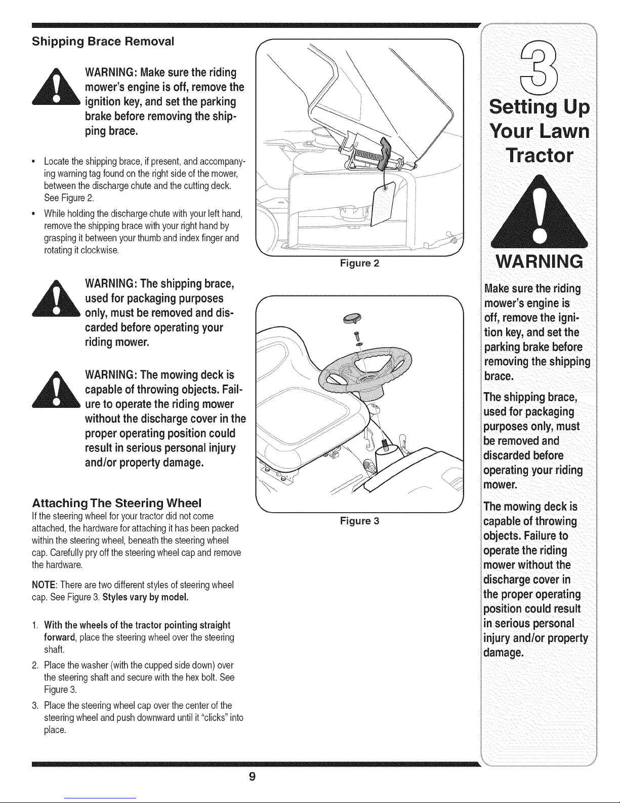
• Locatetheshippingbrace,ifpresent,andaccompany-
ingwarningtagfoundon therightsideof themower,
betweenthedischargechuteandthecuttingdeck.
See Figure2.
• Whileholdingthedischargechutewithyourlefthand,
removetheshippingbracewithyour righthandby
graspingitbetweenyourthumbandindexfingerand
rotatingitclockwise.
WARNING: The shipping brace,
used for packagingpurposes
only, must be removedand dis-
carded before operating your
riding mower.
WARNING: The mowing deck is
capableof throwing objects. Fail-
ure to operate the ridingmower
without the dischargecover in the
proper operating position could
result inserious personal injury
and/or property damage.
Figure 2
TractOr
WARNING
Make surethe riding
mower's engine is
off, removethe igni-
tion key, and set the
parkingbrake before
removingthe shipping
brace.
The shipping brace,
used for packaging
purposes only, must
be removedand
discardedbefore
operatingyour riding
mower.
Attaching The Steering Wheel
Ifthesteeringwheelforyour tractordidnotcome
attached,thehardwareforattachingit hasbeenpacked
withinthesteeringwheel,beneaththe steeringwheel
cap.Carefullypryoffthesteeringwheelcapand remove
thehardware.
NOTE:Therearetwodifferentstylesof steeringwheel
cap.SeeFigure3. Stylesvary by model.
1. With thewheels of the tractor pointingstraight
forward, placethesteeringwheeloverthe steering
shaft.
2. Placethewasher(withthecuppedsidedown)over
thesteeringshaftandsecurewiththehex bolt.See
Figure3.
3. Placethesteeringwheelcapoverthecenterof the
steeringwheelandpushdownwarduntilit"clicks"into
place.
The mowing deckis
Figure 3
capableofthrowing
objects. Failureto
operate the riding
mower withoutthe
dischargecover in
the properoperating
position could result
in serious personal
injuryand/or property
damage.
9
Page 10
WARNING
Beforeoperatingthis
machine,makesure
the seat isengaged in
the seat stop;stand
behindthemachine
andpu,backonseat
fu,yengaged
intostop:
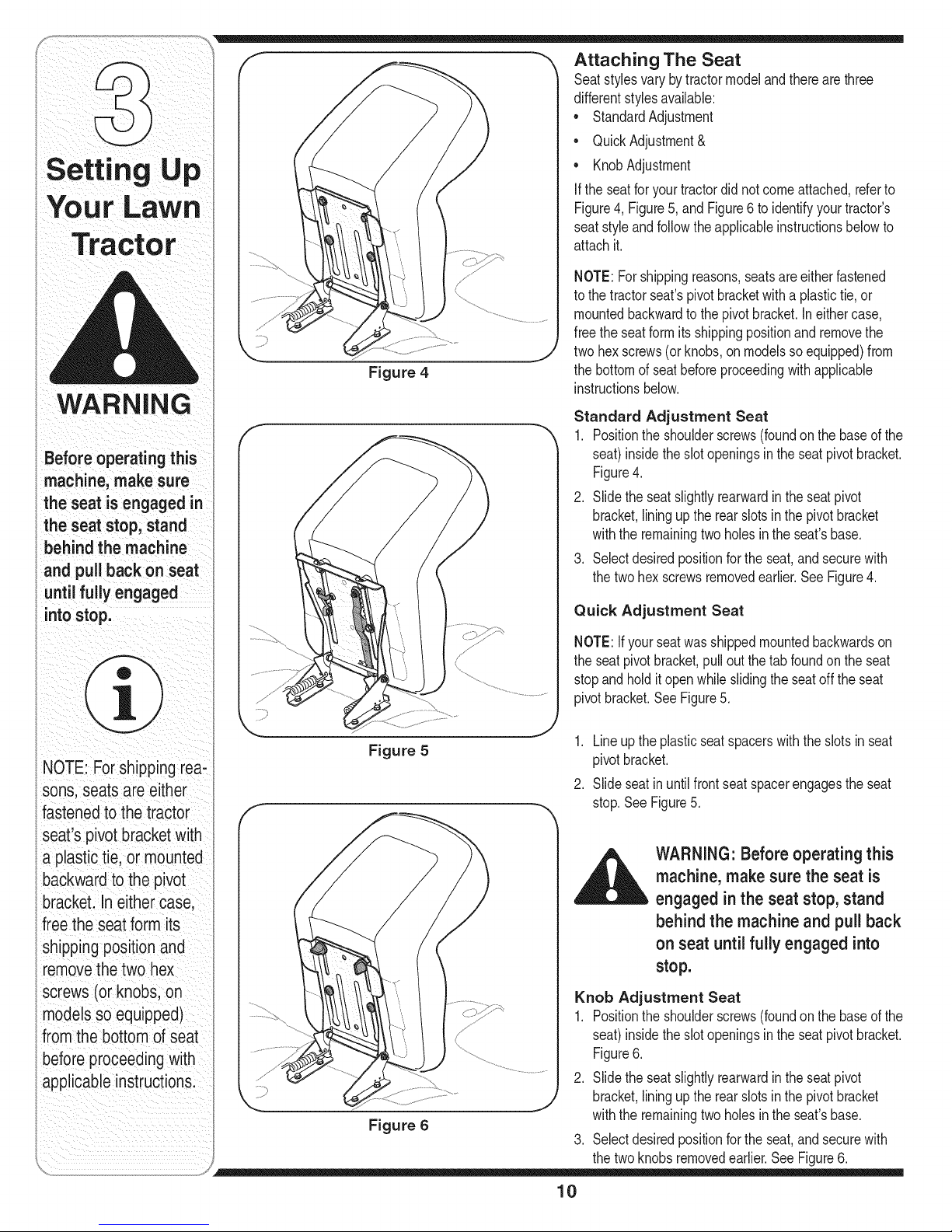
Figure 4
Attaching The Seat
Seatstylesvarybytractormodelandtherearethree
differentstylesavailable:
• StandardAdjustment
• QuickAdjustment&
• KnobAdjustment
If theseatfor yourtractordid notcomeattached,referto
Figure4, Figure5,and Figure6toidentifyyourtractor's
seatstyleandfollowthe applicableinstructionsbelowto
attachit.
NOTE:Forshippingreasons,seatsareeitherfastened
tothe tractorseat'spivotbracketwithaplastictie,or
mountedbackwardtothepivotbracket.Ineithercase,
freethe seatformitsshippingpositionandremovethe
twohexscrews(orknobs,onmodelssoequipped)from
thebottomof seatbeforeproceedingwithapplicable
instructionsbelow.
Standard Adjustment Seat
1. Positiontheshoulderscrews(foundonthe baseof the
seat)insidetheslotopeningsinthe seatpivotbracket.
Figure4.
2. Slidethe seatslightlyrearwardintheseatpivot
bracket,liningupthe rearslots inthepivotbracket
withtheremainingtwo holesinthe seat'sbase.
3. Selectdesiredpositionforthe seat,andsecurewith
thetwohex screwsremovedearlier.SeeFigure4.
Quick Adjustment Seat
NOTE:Ifyour seatwasshippedmountedbackwardson
theseatpivotbracket,pulloutthetab foundonthe seat
stopandholditopenwhileslidingthe seatoff theseat
pivotbracket.SeeFigure5.
NOTE: Forsh pping rea:
s0nsl Seatsareeither
fastenedto the tractor
seat's pivotbraCketWitt
a plastiCtie, or mounted
backwardtothe pivot
bracket. In either case;
free the seatform its
shippingp0sitionand
removethe two Box
screws(or knobsion
models so equipped)
fromthebottom of seat
beforeproceedingwith
applicableinstructions:
Figure 5
Figure 6
1. Lineupthe plasticseatspacerswiththeslotsin seat
pivotbracket.
2. Slideseatinuntilfrontseatspacerengagestheseat
stop.SeeFigure5.
WARNING" Before operating this
machine, make sure the seat is
engaged inthe seat stop, stand
behind the machine and pull back
on seat until fully engaged into
stop.
Knob Adjustment Seat
1. Positiontheshoulderscrews(foundonthe baseof the
seat)insidetheslotopeningsinthe seatpivotbracket.
Figure6.
2. Slidethe seatslightlyrearwardintheseatpivot
bracket,liningupthe rearslots inthepivotbracket
withtheremainingtwo holesinthe seat'sbase.
3. Selectdesiredpositionforthe seat,andsecurewith
thetwoknobsremovedearlier.SeeFigure6.
10
Page 11
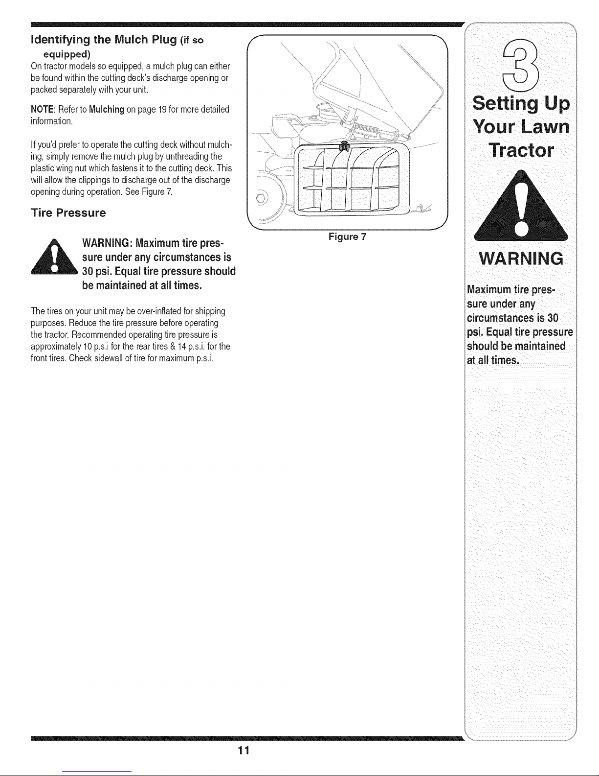
identifying the Mulch Plug (if so /,f
equipped)
On tractormodelssoequipped,amulchplugcan either
be foundwithinthe cuttingdeck'sdischargeopeningor
packedseparatelywithyourunit.
NOTE:Referto Mulching on page19for moredetailed
information.
Ifyou'dprefertooperatethecuttingdeckwithoutmulch-
ing,simplyremovethemulchplugby unthreadingthe
plasticwing nutwhichfastensit tothecuttingdeck.This
willallowtheclippingsto dischargeoutof thedischarge
openingduringoperation.SeeFigure7.
Tire Pressure
|
Figure 7
,_ WARNING: Maximum tire pres-
Thetiresonyour unitmaybeover-inflatedforshipping
purposes.Reducethetire pressurebeforeoperating
thetractor.Recommendedoperatingtirepressureis
approximately10p.s.iforthe reartires& 14p.s.i,forthe
fronttires.Checksidewallof tireformaximump.s.i.
sure underany circumstances is
30 psi.Equal tire pressure should
be maintainedat all times.
WARNING
Maximumtirepres,
sure under any
circumstancesis30
psi, Equaltire pressure
shouldbe maintained
at all times,
11
Page 12

NOTE:Any reference
in this manualto the
RIGHTor LEFTside of
thetractor isobserved
from operator'sposition.
Know Your Lawn Tractor
A
NOTE:Anyreferencein thismanualto theRIGHTor LEFTsideof thetractorisobservedfromoperator'sposition.
NOTE:Steeringwheelnot shownforclarity
Figure 8
A SpeedControlLever/ParkingBrake E ThrottleControlLever
B Clutch-BrakePedal F IgnitionSwitchModule
C ShiftLever G DeckLiftLever
D ChokeControl1- H PTO(BladeEngage)Lever
12
1-If soequipped
Page 13

Throttle Control Lever
Thethrottlecontrolleveris locatedon therightside of
thetractor'sdashpanel.Thislevercontrolsthespeed
ofthe engineand,on somemodels,whenpushedall
thewayforward,thechokecontrolalso.Whenset ina
givenposition,thethrottlewill maintainauniformengine
speed.SeeFigure9.
IMPORTANT:Whenoperatingthetractorwiththecutting
deckengaged,becertainthatthe throttleleverisalways
inthe FAST(rabbit)position.
FAST--4pm
|l
Choke Control
Onsomemodels,movingthe
throttleleverallthewayforward
activatestheengine'schoke _L._
control.Onall othermodels,the
chokecontrolcanbefoundon
theleftside ofthedashpanel
andisactivatedby pullingthe
knoboutward.Activatingthe
chokecontrolclosesthe choke
plateonthe carburetorandaidsinstartingtheengine.
RefertoStarting The Engineon page16ofthis manual
fordetailedstartinginstructions.
Ignition Switch
Theignitionswitchisactivatedtostarttheengine.Insert
keyintotheignitionswitchandturnclockwiseto the
STARTposition.ReleasethekeyintotheON position
onceenginehasfired.SeeFigure10A.
ignition Switch Module (if Equipped)
Tostart theengine,insertthekeyintothe ignitionswitch
andturnclockwisetothe STARTposition.Releasethe
keyintothe NORMALMOWINGMODEpositiononce
theenginehasfired.
Tostopthe engine,turntheignitionkeycounterclockwise
tothe OFFposition.SeeFigurelOB.
SLOW __ .,-.--.
Off
Position
SLOW
Figure 9
n/Lights
Start
Normal
i _ i : iii ii I ii i_/I
WARNING
lever leave a running
machine unattended,
Alwaysdisengage
PTO,move shift lever
nto neutral position,
set parking ake, stop
engine and remove key
to preventunintended
startingl
Mode
WARNING: Never leave a running
machine unattended, Always
disengage PTO,move shift lever
intoneutral position, set parking
brake, stop engine and remove
key to prevent unintended
starting,
IMPORTANT:Priortooperatingthetractor,referto both
SafetyInterlock Switches onpage14andStarting
TheEngine onpage16of thismanualfordetailed
instructionsregardingthe IgnitionSwitchModuleand
operatingthetractorin REVERSECAUTIONMODE.
Start
Position
©
Figure 10
Deck Lift Lever
Foundonyourtractor'srightfender,thedeckliftleveris
usedto changetheheightof thecuttingdeck.Touse,
movethelevertothe left,then placeinthenotchbest
suitedforyour application.
13
IMPORTANT
Priortooperatingthe
tractor, referto both
Safety Interlock
Switchesonpag
14and
Engine 0n page i6
ofthismanualior
regardingthe Ignition
Switch Moduleand
operating the tractor in
REVERIE CAUTION
MODEi
Page 14

FORWARD
HUETRAL
Speed Control Lever
Thespeedcontrollever,locatedonthe
left sideof thetractor'sdashconsole,
allowsyouto regulatethegroundspeed
ofthe lawntractor.Touse,depressthe
clutch-brakepedalandmovethe leveroul
ofthe parkingbrakenotchandforward
toincreasethetractor'sgroundspeed.
Whenadesiredspeedhasbeenreached
releasetheleverintoan appropriate
notchto maintainthatspeed.
Toslowthe tractor'sgroundspeed,
depresstheclutch-brakepedalandmove
thespeedcontrolleverrearwardand
releaseit intoa notch.
NOTE:Theparking
brakemustbesetifthe
operatorleavestheseat
withtheenginerun-
ningortheenginewill
automaticallyshutoff.
NOTE:ThePTO(Blade
Engage)levermustbe
inthedisengaged(PTO
:3FF)positionwhen
startingtheengine.
iMPORTANT
Neverforce the shift
lever.Doing so may
resultin senous
damageto thetractor's
transmission.
REVERSE_
Figure 11
Parking Brake
Tosetthe parkingbrake,fullydepressthe clutch-brake
pedal.Movethe speedcontrolleverallthewaydown
andintothe parkingbrakeposition.Releasetheclutch-
brakepedalto allowthe parkingbraketoengage.
Toreleasetheparkingbrake,depresstheclutch-brake
pedaland movethespeedcontrolleveroutofthe
notchestothedesiredposition.Releasethespeed
controlleverandthe clutch-brakepedal.
NOTE:Theparkingbrakemustbesetif theoperator
leavestheseatwiththe enginerunningor theengine
willautomaticallyshutoff.
Clutch-Brake Pedal
Theclutch-brakepedalis locatedontheleft sideof
thelawntractor,alongtherunningboard.Depressthe
clutch-brakepedalpartwaydownwhenslowingthe
tractorbychangingspeeds(Referto SpeedControl
Lever).Depressthepedalall thewaydowntoengage
thedisc brakeand bringthetractortoa completestop.
NOTE:Thepedalmustbedepressedto startthe
engine.Referto SafetyInterlockSwitcheson page14.
Shift Lever
Theshiftleverislocatedon theleftsideof thefender
andhasthree positions,FORWARD,NEUTRALand
REVERSE.Thebrakepedalmustbedepressedand
thetractor mustnotbe inmotionwhenthe movingshift
lever.SeeFigure11.
IMPORTANT:Neverforcetheshiftlever.Doingsomay
resultinseriousdamagetothetractor'stransmission.
NOTE:Lawntractorsvarybymodeland
areavailablewitheithera 6- or 7-speed
controllever.
PTO (Blade Engage) Lever
Foundonthe tractor'srightfender,the
PTO(bladeengage)leveris usedto
engagepowertothecuttingdeckor
other(separatelyavailable)attachments.
Tooperate,movethe leverallthe way
forward.Movingtheleverallthe way
rearwardintothePTOOFFposition
disengagespowertothecuttingdeck/
attachment.
NOTE:The PTO(bladeengage)lever
mustbe inthe disengaged(PTOOFF)
positionwhenstartingtheengine.
z
!2
,t
_3
_4
!
_5
o
" #
Safety Interlock Switches
Thistractorisequippedwitha safetyinterlocksystem
forthe protectionof theoperator.Ifthe interlocksystem
shouldevermalfunction,donotoperatethetractor.
ContactanauthorizedMTDservicedealer.
* Thesafetyinterlocksystempreventstheengine
fromcrankingor startingunlessthe parkingbrakeis
engaged,andthe PTO(BladeEngage)leverisinthe
disengaged(OFF)position.
* Theenginewillautomaticallyshutoffif theoperator
leavestheseatbeforeengagingtheparkingbrake.
* Theenginewillautomaticallyshutoffif theoperator
leavesthetractor'sseatwiththePTO(BladeEngage)
leverinthe engaged(ON)position,regardlessof
whetherthe parkingbrakeis engaged.
* Theenginewillautomaticallyshutoffif theoperator
engagesthePTOwiththe parkingbrakeON.
14
Page 15

Models without Reverse Caution Mode
• Theenginewillautomaticallyshutoffifthe PTO
(BladeEngage)leveris movedintothe engaged(ON)
positionwiththeshiftleverin Reverse.
Models with Reverse Caution Mode
• Withtheignitionkeyinthe NORMALMOWING
position,theenginewillautomaticallyshutoff ifthe
PTO(BladeEngage)leverismovedintotheengaged
(ON)positionwiththe shiftleverin Reverse.
F
Indicator
Light
Stop
Position
©
Reverse
.PushButton
Reverse
CautionMode
Position
Start
Position
_ _ii ii_i i_iii_ii_ i?_i_i_i_ii_ ii__
,_ WARNING: Do not operate the
tractor if the interlocksystem
ismalfunctioning.This system
was designed for your safetyand
protection.
Reverse Caution Mode (if Equipped)
WARNING: Useextreme caution
while operating the tractor in
the REVERSE CAUTION MODE.
Always lookdown and behind
before and while backing. Do not
operate the tractor when children
or others are around, Stop the
tractor immediatelyif someone
enters the area.
TheREVERSECAUTIONMODEpositionofthe key
switchmoduleallowsthetractorto be operatedin
reversewiththeblades(PTO)engaged.
IMPORTANT:Mowinginreverseisnotrecommended.
Tousethe REVERSECAUTIONMODE:
IMPORTANT:TheoperatorMUSTbeseatedinthe
tractorseat.
1. Startthe engineasinstructedonpage16under
Starting The Engine.
2. Turnthekeyfromthe NORMALMOWING(Green)
positiontothe REVERSECAUTIONMODE(Yellow)
positionofthe keyswitchmodule. SeeFigure12.
3. DepresstheREVERSEPUSHBUTTON(Orange,
TriangularButton)atthetop,rightcornerof thekey
switchmodule.Theredindicatorlightat thetop,left
cornerof thekeyswitchmodulewillbe ONwhile
activated.SeeFigure12.
Figure 12
4. Onceactivated(indicatorlightON),the tractorcan
bedriveninreversewiththecuttingblades(PTO)
engaged.
5. Alwayslookdownandbehindbeforeandwhile
backingtomakesurenochildrenarearound.
6. Afterresumingforwardmotion,returnthekeytothe
NORMALMOWINGposition.
IMPORTANT:TheREVERSECAUTIONMODEwill
remainactivateduntil:
a. The keyisplacedineithertheNORMALMOWING
positionor STOPposition.
b.The operatorengagestheparkingbrakebyfully
depressingtheclutch-brakepedalandholdingit
downwhile movingthespeedcontrolleverintothe
PARKBRAKEposition.
Engaging the Parking Brake
Toengagethe parkingbrake:
1. Fullydepresstheclutch-brakepedalandholdit down
withyourfoot.
2. Movethe speedcontrolleverall thewaydownand
intothe parkingbrakeposition.
3. Releasetheclutch-brakepedalto allowthe parking
braketoengage.
Toreleasetheparkingbrake:
1. Depresstheclutch-brakepedalandmovethe speed
controlleveroutofthe parkingbrakepositionandinto
a desiredspeed.
WARNING
Do not operate the
tractor if the interlock
system is malfunction-
ing. This system was
designed for your
safety and protection.
Use extreme caution
while operating the
tractor inthe REVERSE
CAUTION MODE.
Always look down and
behind beforeand
while backing. Do not
operate the tractor
when children or oth-
ers are around. Stop
the tractor immediately
f someone enters the
area.
15
Page 16

YoUr LaWn
Tractor
WARNING
Keephands and feet
awayfrom the dis-
charge opening of the
cuttingdeck.
Setting the Cutting Height
1. Selectthe heightpositionofthecuttingdeckby
placingthedeckliftleverinanyof thesixdifferent
cuttingheightnotchesonthe rightsideofthe fender.
2. Adjustthe deckwheels,ifequipped,sothattheyare
betweenl_-inchandY2-inchabovethegroundwhen
thetractor isona smooth,flat surfacesuchasa
driveway.
i
WARNING: Keep hands and feet
away from the discharge open-
ing ofthe cutting deck.
NOTE:Onmodelsso equipped,thedeckwheelsare an
anti-scalpfeatureofthedeckandare notdesignedto
supporttheweightof thecuttingdeck.
Referto Levelingthe Deckonpage20ofthis manual
formoredetailedinstructionsregardingvariousdeck
adjustments.
Starting the Engine
,,__ WARNING" Do not operate the
tractor if the interlocksystem is
malfunctioning. This system was
designed for your safety and
protection.
I G
AVOID SERIOUS INJURY OR DEATH
GO UPAND DOWNSLOPES,NOTACROSS.
AVOIDSUDDENTURNS.
DO NOT OPERATETHEUNITWHEREIT COULDSLIPOR TIE
IF MACHINESTOPSGOINGUPHILL,STOPBLADE(S)AND
BACKDOWNHILLSLOWLY.
DO NOT MOWWHEN CHILDRENOROTHERSAREAROUND.
NEVERCARRYCHILDREN,EVENWITHBLADESOFR
LOOK DOWNAND BEHIND BEFOREANDWHILEBACKING.
KEEPSAFETYDEVICES(GUARDS,SHIELDS,ANDSWITCHES)
IN PLACEANDWORKING.
REMOVEOBJECTSTHATCOULDBE THROWNBYTHE
BLADE(S).
KNOWLOCATIONANDFUNCTIONOFALLCONTROLS.
BE SUREBLADE(S)ANDENGINEARE STOPPEDBEFORE
PLACINGHANDSORFEETNEAR BLADE(S).
BEFORELEAVINGOPERATOR'SPOSITION,DISENGAGE
BLADE(S), PLACETHE SHIFTLEVERIN NEUTRAL,ENGAGE
BRAKELOCK,SHUTENGINEOFFAND REMOVEKEY.
READ OPERATOR'S MANUAL
Stopping the Engine
Donot operatethe
tractor ifthe interlock
system ismalfunction-
ing.This systemwas
designed for your
safety and protection.
if you strike aforeign
object, stopthe
engine, disconnect
the spark plugwire(s)
and ground against
the engine. Thoroughly
inspectthe machine
for any damage. Repair
the damage before
restartingand operat-
ing.
NOTE:Referto theTRACTORSET-UPon page8 of
thismanualforGasolineandOil fill-upinstructions.
1. Insertthetractorkeyintothe ignitionswitch.
2. PlacethePTO(BladeEngage)leverinthe disen-
gaged(OFF)position.
3. Engagethetractor'sparkingbrake.
4. Activatethechokecontrol.
5. TurntheignitionkeyclockwisetotheSTARTposi-
tion.Aftertheenginestarts,releasethekey.Itwill
returnto theONposition.
IMPORTANT:DoNOTholdthe keyin theSTART
positionforlongerthantensecondsata time. Doingso
maycausedamagetoyourengine'selectricstarter.
6. Afterthe enginestarts,deactivatethe chokecontrol
andplacethe throttlecontrolinthe FASTposition.
NOTE:Do NOTleavethe chokecontrolonwhileoperat-
ingthetractor.Doingsowill resultina "rich"fuelmixture
andcausetheengineto runpoorly.
__ ARNING: if you strike a foreign
object, stop the engine,discon-
nect the spark plug wire(s) and
ground against the engine. Thor-
oughly inspectthe machine for
any damage. Repair the damage
before restarting and operating
1. If thebladesareengaged,placethe PTO(Blade
Engage)leverinthe disengaged(OFF)position.
2. Turntheignitionkeycounterclockwisetothe STOP
position.
3. Removethekeyfromthe ignitionswitchtoprevent
unintendedstarting.
16
Page 17

Driving The Tractor
WARNING: Avoidsudden starts,
e×-cessivespeed and sudden
stops.
WARNING: Do not leave the seat
of the tractor without first plac-
ingthe PTO(Blade Engage) lever
inthe disengaged (OFF) posi-
tion, depressing the brake pedal
and engaging the parking brake.
if leaving the tractor unattended,
also turn the ignitionkey off and
remove the key.
Always look down and behind
before and while backing up to
avoid a back-over accident.
1. Depressthebrakepedalto releasetheparkingbrake
andletthe pedalup.
2. Movethe throttleleverintotheFAST(rabbit)position.
3. Placetheshiftleverin eithertheFORWARDor
REVERSEposition.
IMPORTANT:DoNOTusetheshiftlevertochangethe
directionoftravelwhenthetractorisin motion.Always
usethe brakepedalto bringthetractortoa complete
stopbeforeshifting.
4. Releasetheparkingbrakebydepressingtheclutch-
brakepedalandpositioningthespeedcontrolleverin
desiredposition.
IMPORTANT:First-timeoperatorsshouldusespeed
positions1or2. Becomecompletelyfamiliarwiththe
tractor'soperationandcontrolsbeforeoperatingthe
tractorinhigherspeedpositions.
.
Releaseclutch-brakepedalslowlyto putunit into
motion.
6.
Thelawntractoris broughttoa stopbydepressing
theclutch-brakepedal.
NOTE:Whenoperatingtheunitinitially,therewillbe little
differencebetweenthehighesttwospeedsuntilafterthe
beltshaveseatedthemselvesintothe pulleysduringthe
break-inperiod.
operator's positionfor any
_ ARNING: Before leaving the
reason, disengage the blades,
place the shift lever inneutral,
engage the parking brake, shut
engine off and remove the key.
IMPORTANT:Whenstoppingthetractorfor anyreason
whileona grasssurface,always:
1. Placetheshift leverinneutral,
2. Engagetheparkingbrake,
3. Shutengineoff andremovethekey.
Doingsowillminimizethepossibilityofhavingyourlawn
"browned"byhot exhaustfromyourtractor'srunning
engine.
If unit stalls withspeedcontrolin highspeed,orif unit
willnot operatewithspeedcontrolleverin alowspeed
position,proceedasfollows:
1. Placeshiftleverin NEUTRAL.
2. Restartengine.
3. Placespeedcontrolleverinhighestspeedposition.
4. Releaseclutch-brakepedalfully.
5. Depressclutch-brakepedal.
6. Placespeedcontrolleverindesiredposition.
7. Placeshiftleverin eitherFORWARDorREVERSE,
andfollownormaloperatingprocedures.
WARNING
Avoid sudden starts,
ex-cessive speed and
sudden stops.
Do not leave the seat
of the tractor without
first placingthe PTO
(Blade Engage)lever in
the disengaged (OFF)
position,depressing
the brake pedal and
engaging the parking
brake, if leavingthe
tractor unattended,
also turn the ignition
key off and remove the
key.
Always look down
and behind before
and while backing up
to avoid a back-over
_ccident.
17
Page 18

Driving On Slopes
Refertothe SLOPEGAUGEon page3 tohelpdeter-
mineslopeswhereyoumayoperatethetractorsafely.
Using the Deck Lift Lever
Toraisethecuttingdeck,movethe decklift levertothe
left,thenplaceitinthe notchbestsuitedforyourapplica-
tion.RefertoSettingThe CuttingHeightearlierinthis
section.
WARNING
Donot mow on inclines
with a slopein excess
of 15degrees (a rise
of approximately 2-1/2
feet every 10 feet). The
tractor could overturn
and cause serious
injury.
Tohelp avoid blade
;ontact or a thrown
object injury, keep
bystanders, helpers,
;hildren and pets at
least75 feet from the
machine while it is in
operation. Stop ma-
;hine if anyoneenters
thearea.
inclineswith a slope in excess
,_ WARNING: Do not mow on
of 15degrees (a rise of approxi-
mately 2-1/2feet every 10feet).
The tractor could overturnand
cause serious injury.
• Mowupanddownslopes,NEVERacross.
• Exerciseextremecautionwhenchangingdirection
on slopes.
• Watchforholes,ruts,bumps,rocks,orotherhidden
objects.Uneventerraincouldoverturnthe machine.
Tallgrasscan hideobstacles.
• Avoidturnswhendrivingonaslope.Ifa turnmust
be made,turndowntheslope.Turningupa slope
greatlyincreasesthechanceofa rollover.
• Avoidstoppingwhendrivingupaslope.If itis
necessarytostopwhiledrivingup aslope,startup
smoothlyandcarefullyto reducethepossibilityof
flippingthetractoroverbackward.
Engaging the Blades
EngagingthePTO(BladeEngage)transferspowerto
thecutting deckor other(separatelyavailable)attach-
ments.Toengagethe blades,proceedasfollows:
1. Movethe throttlecontrollevertotheFAST(rabbit)
position.
2. GraspthePTO(BladeEngage)leverandpivotit all
thewayforwardinto theengaged(ON) position.
3. Keepthe throttleleverinthe FAST(rabbit)position
forthe mostefficientuseofthe cuttingdeckorother
(separatelyavailable)attachments
iMPORTANT:ModelswithReverseCaution Mode:
Theenginewill automaticallyshutoff ifthePTOis
engagedwiththeshift leverin positionfor reversetravel
withtheignitionkeyintheNORMALMOWINGposition.
Models withoutReverseCautionMode:
ThePTO(BladeEngage)levermustbein thedisen-
gaged(OFF)positionwhenstartingtheengine,when
travelingin reverse,and if theoperatorleavestheseat.
RefertoSafetyinterlockSwitchesonpage14.
Mowing
WARNING: To help avoid blade
contact or a thrown object injury,
keep bystanders, helpers, children
and petsat least 75feet from the
machine while it is in operation.
Stop machine ifanyone enters the
area.
Thefollowinginformationwillbehelpfulwhenusingthe
cuttingdeckwith yourtractor:
WARNING: Planyour mowing
pattern to avoid discharge of
materials toward roads, sidewalks,
bystanders and the like. Also,
avoid discharging material against
a wall or obstruction which may
cause discharged material to
ricochet back toward the operator.
• Do notmowathighgroundspeed,especiallyifa
mulchkit orgrasscollectorisinstalled.
• For bestresultsitis recommendedthatthefirsttwo
lapsbe cutwiththe dischargethrowntowardsthe
center.Afterthefirsttwolaps, reversethedirectionto
throwthedischargetotheoutsidefor thebalanceof
cutting.Thiswillgivea betterappearanceto the lawn.
• Do notcutthegrasstoo short.Shortgrassinvites
weedgrowthandyellowsquicklyindry weather.
• Mowingshouldalwaysbedonewiththeengineat full
throttle.
Underheavierconditionsitmaybenecessarytogo
backoverthecut areaa secondtimetogeta clean
cut.
18
Page 19

• DoNOTattempttomowheavybrushandweedsand _ _ " --
extremelytallgrass.Yourtractoris designedtomow /A I
awns,NOTdearbrush //I
• Keepthebladessharpand replacethebladeswhen "i.: ....",,, [J
worn.Referto Cutting Bladeson page25ofthis / '
manualforproperbladesharpeninginstructions.
Mulching (If Equipped)
Selectmodelscomeequippedwitha mulchkitwhich
incorporatesspecialblades,alreadystandardonthe
tractor,ina processof recirculatinggrassclippings
repeatedlybeneaththecuttingdeck.Theultra-fine
clippingsarethenforcedbackintothe lawnwherethey
actasa naturalfertilizer.
Observethefollowingpointsfor thebestresultswhen
mulching:
• Neverattempttomulchif the lawnisdamp.Wetgrass
tendsto stickto theundersideofthecuttingdeck
preventingpropermulchingofthe clippings.
• DoNOTattempttomulchmorethan1/3thetotal
heightof thegrassor approximately1-1/2inches.
Doingso willcausetheclippingstoclumpup beneath
thedeckand notbe mulchedeffectively.
• Maintainaslowgroundspeedtoallowthegrass
clippingsmoretimeto effectivelybemulched.
• AlwayspositionthethrottlecontrolleverintheFAST
(rabbit)positionandallowitto remaintherewhile
mowing.Failingtokeeptheengineat fullthrottle
placesstrainon thetractor'sengineanddoesnot
allowthe bladesto properlymulchgrass.
NOTE:It is notnecessarytoremovethedischargechute
tooperatethemowerwiththe mulchkit installed.
Tooperatethecuttingdeckwithoutmulching,simply
removethemulchplugbyunthreadingtheplasticwing
nutwhichfastensit tothe cuttingdeck.Thiswillallowthe
clippingstodischargeouttheside.See Figure13.
Operating
Figure 13
WARNING
Planyour mowing pat-
tern to avoid discharge
of materials toward
roads, sidewalks, by-
standers and the like.
Also, avoid discharging
_aterial against a wall
_robstruction which
may cause discharged
aterial to ricochet
back toward the
operator.
Headlights
• Onsomemodels,thelampsareONwheneverthe
tractor'sengineisrunning.Onothermodels,the
lampsareONwhenevertheignitionkeyis movedout
ofthe STOPposition.
• Onall models,thelampsturn OFFwhenthe ignition
keyismovedto theSTOPposition.
19
Page 20

WARNING
Neverattemptto
make any adjust-
ments while the
engine isrunning,
exceptwhere speci-
i fied in the operator's
manual.
iNever attempt to
iadjust the brakes
_whiethe engine
iisrunning. Always
idisengage PTO, move
::shift lever intoneutral
position, stop engine
and remove key to
iprevent unintended
istarting.
Figure 14
Figure 15
,_ WARNING: Never attempt to
make any adjustments while
the engine isrunning, except
where specified in the operator's
manual.
1. Withthe tractorparkedona firm,levelsurface,place
thedecklift leverin thetopnotch(highestposition)
androtatethebladenearestthedischargechuteso
thatitis parallelwiththetractor.
2. Measurethedistancefromthe frontofthe bladetipto
thegroundandthe rearofthe bladetiptotheground.
Thefirst measurementtakenshouldbebetween
1/4"and 3/8"lessthanthesecondmeasurement.
Determinetheapproximatedistancenecessaryfor
properadjustmentandproceed,ifnecessary,tothe
nextstep.
3. Locatethejamnut andlocknutonthefrontsideof the
stabilizerbracket.See Figure14.Afterlooseningthe
jamnut:
Tightenthelocknutto raisethefrontof thedeck;
Loosenthelocknutto lowerthefrontofthe deck.
4. Retightenthejam nutloosenedearlierwhenproper
adjustmentisachieved.
Side to Side
If thecuttingdeckappearsto bemowingunevenly,a side
toside adjustmentcan beperformed.Adjustif necessary
asfollows:
1. Withthe tractorparkedona firm,levelsurface,place
thedecklift leverin thetopnotch(highestposition)
androtatebothbladessothattheyareperpendicular
withthetractor.
2. Measurethedistancefromthe outsideoftheleftblade
tipto thegroundandthe distancefromtheoutsideof
therightbladetipto theground.Bothmeasurements
takenshouldbeequal. Ifthey'renot,proceedtothe
nextstep.
3. Loosen,butdo NOTremove,the hexcapscrewon
theleftdeckhangerbracket.SeeFigure15.
4. Balancethedeckby usingawrenchtoturnthe
adjustmentgear (foundimmediatelybehindthehex
capscrewjust loosened)clockwise/uporcounter-
clockwise/down.Thedeckis properlybalancedwhen
bothbladetip measurementstakenearlierareequal.
5. Retightenthehex capscrewontheleft deckhanger
bracketwhenproperadjustmentisachieved.
Parking Brake Adjustment
Leveling the Deck
NOTE:Checkthetractor'stirepressurebeforeperform-
inganydeck levelingadjustments.RefertoTires on
page24 forinformationregardingtirepressure.
Front To Rear
Thefrontof thecuttingdeckissupportedbya stabilizer
barthatcanadjustedto levelthe deckfromfrontto rear.
Thefrontof thedeckshouldbebetween1/4-inchand
3/8-inchlowerthantherearof thedeck.Adjustif
necessaryasfollows:
_ ARNING"Never attempt to ad-
just the brakes while the engine is
running. Always disengage PTO,
move shift lever into neutral posi-
tion, stop engine and remove key
to prevent unintended starting.
If thetractordoesnotcometoa completestopwhenthe
brakepedalis completelydepressed,or if thetractor's
rearwheelscanrollwiththe parkingbrakeapplied,the
2O
Page 21

brakeis in needofadjustment.Thebrakedisccanbe
foundon the rightsideof thetransmissionintherearof
thetractor.Adjustif necessaryasfollows:
1. Lookingatthetransmissionfromthe rightsideofthe
tractor,locatethecompressionspringandbrakedisc.
See Figure16.
2. Loosen,butdo NOTremove,the hexnutfoundon the
rightsideofthe brakeassembly.SeeFigure16.
3. Usingafeelergauge,setthe gapbetweenthe brake
discandthebrakepuckat.011".
4. Re-tightenthehexnutloosenedearlier.
Seat Adjustment
Adjusting
urLawn
_ ARNING: Before operating this
machine,make sure the seat is
engaged in the seat stop, stand
behind the machine and pull back
on seat until fully engaged into
stop.
Standard Seat
Toadjustthe positionofthe seat,loosenthetwohex
screwson thebottomofthe seat.Slidetheseatforward
or backwardas desired.Retightenthe twoscrews.See
Figure17.
Knob Adjustment Seat (if so equipped)
Toadjustthe positionofthe seaton modelssoequipped,
loosenthe twoknobson thebottomoftheseat. See
Figure18.Slidetheseatforwardorbackwardasdesired.
Retightenthetwoknobs.
Quick Adjust Seat (if so equipped)
Toadjustthe positionofthe seaton modelsequipped
witha seatadjustmentlever,movetheseatadjustment
lever(locatedundertheseat)tothe leftand slidetheseat
forwardor rearward.SeeFigure19.Makesureseatis
lockedintopositionbeforeoperatingthetractor.
Set gap
Figure 16
Figure 17
Hex Nut
WARNING
Before operating this
machine, make sure
the seat is engaged in
the seat stop, stand
behind the machine
and pull back on seat
until fully engaged into
stop.
\
Figure 19 Figure 18
.....J
21
Page 22

WARNING
any maintenance or
repairs,disengage
PTO,move shift lever
intoneutralposition,
set parkingbrake, stop
engine and remove key
o preventunintended
_tarting!
Before lubricatingi
repairing, or inspect,
ing,always disengage
PTOImove shift lever
into neutral position,
set parking brake, stop
engineandremovekey
to preventunintended
startingl
NOTE:Dependingon
the engine model found
Onyour tractorl itmay
be necessaryto remove
thetractor!s side panel
in OrdertOreplacethe
oilfilter (ifso equipped):
Figure 20
,_ WARNING: Before performing
any maintenance or repairs,
disengage PTO,move shift lever
intoneutral position, set parking
brake, stop engine and remove
key to prevent unintended
starting.
Engine
Referto the EngineOperator/Owner Manualfor
engine maintenanceinstructions.
Checkengineoil levelbeforeeachuseas instructed
inthe EngineOperator/OwnerManualpackedwithyour
unit.Follow the instructionscarefully.
Changing Engine Oil
NOTE:Dependingontheenginemodelfoundon your
tractor,itmaybenecessaryto removethetractor'sside
panelin ordertoreplacetheoilfilter(if soequipped).
Fordrainingoilfromthe engine'scrankcaseofselect
modeltractors,a plasticoildrainsleeveis packedwith
thisOperator'sManual.Todraintheoil,proceedas
follows:
1. Unscrewtheoilfill capand removethedipstickfrom
theoil fill tube.
2. Snapthe smallendofoildrainsleeveontotheoil
sump.SeeFigure20.
3. Removedrainpluganddrainoil intoasuitable
containerwitha capacityofno lessthan64oz.
4. Servicethe oilfilter (if soequipped)as instructedin
theseparateEngineOperator/OwnerManualpacked
withyourunit.
Performtheabovestepsinthe oppositeorderafteroil has
finisheddraining.
5. Refillthe enginewith newmotoroil asinstructedinthe
EngineOperator/OwnerManualpackedwithyour unit.
IMPORTANT:Refertothe EngineOperator/Owner
Manualpackedwithyourunitfor informationregardingthe
quantityandproperweightof motoroil.
Air Cleaner
Servicethepre-cleaner,if soequipped,andcartridge/air
cleanerelementasinstructedin theEngineOperator/
OwnerManualpackedwithyourunit.
Spark Plug(s)
Thesparkplug(s)shouldbecleanedand thegap reset
oncea season.Sparkplugreplacementisrecommended
atthe startof eachmowingseason.RefertotheEngine
Operator/OwnerManualforcorrectplugtypeandgap
specifications.
Lubrication
WARNING: Before lubricating,
repairing, or inspecting,always
disengage PTO,move shift lever
intoneutral position,set parking
brake, stop engine and remove
key to prevent unintended start-
ing.
Engine
Lubricatetheenginewithmotoroil as instructedinthe
EngineOwnerManualpackedwith yourunit.
Pivot Points & Linkage
Lubricateall thepivotpointsonthe drivesystem,parking
brakeandlift linkageatleastoncea seasonwithlightoil.
Rear Wheels
Therearwheelsshouldbe removedfromthe axlesonce
a season.Lubricatethe axlesandtherimswell withan
all-purposegreasebeforere-installingthem.
Front Axles
Eachendof thetractor'sfrontpivotbarmaybeequipped
witha greasefitting.Lubricatewitha greasegunafter
every25 hoursof tractoroperation.
Cleaning the Engine And Deck
Anyfuel oroil spilledonthemachineshouldbewiped
off promptly.DoNOTallowdebristo accumulatearound
thecoolingfinsofthe engineor onanyotherpartofthe
machine.
IMPORTANT:Theuseofa pressurewasherto cleanyour
tractoris NOTrecommended.It maycausedamageto
electricalcomponents,spindles,pulleys,bearingsor the
engine.
22
Page 23

Deck Wash System TM
A hexplugcan befoundonyourtractor'sdecksurface.
SeeFigure21.
Thisplugcanbe replacedwitha waterporttobeusedas
partof a separately-availabledeckwashsystem.
UsetheDeckWashSystemTM to rinsegrassclippings
fromthedeck'sundersideandpreventthe buildupof
corrosivechemicals.
NOTE:Referto page28forinformationregardingthis
andotherseparately-availableattachments& acces-
soriesforyourtractor.
Cutting Deck Removal
NOTE:Modelsequippedwitha 38-inchdeckhaveone
deckidlerpulley.Modelsequippedwitha 42-inchdeck
havetwodeckidlerpulleys.
Toremovethecuttingdeck, proceedasfollows:
1. PlacethePTO(BladeEngage)leverinthe disen-
gaged(OFF)positionandengagetheparkingbrake.
2. Lowerthedeckby movingthedeckliftleverinto the
bottomnotchonthe rightfender.
3. Removethe beltfromaroundthetractor'sengine
pulleyandidlerpulley(s).Referto ChangingtheDeck
Belton page26 fordetailedinstructions.
4. Lookingatthe cuttingdeckfromtheleft sideof the
tractor,locatethehairpinclip thatsecuresthedeck
supportrodon therearleftsideofthe deck.See
Figure22.
5. Removethe hairpinclipthat securesthedeck
supportrod,andcarefullyremovethedecksupport
fromthedecklift arm.
6. Repeattheabovestepson thetractor'srightside.
7. Movethe decklift leverintothe topnotchonthe right
fenderto raisethe deckliftarmsupandoutofthe
way.
8. CarefullyremovethePTOcablefromthe rearof
thecuttingdeckbyremovingthehair pinclipwhich
securesit.Removethe springfromthedeckidler
bracket.SeeFigure23.
9. Gentlyslidethecuttingdecktowardthefrontof the
tractorallowingthehooksonthe decktorelease
themselvesfromthedeckstabilizerrod.
10.Gentlyslidethecuttingdeck(fromtherightside)out
fromunderneaththetractor.
Figure 21
tOTE: Models
equippedwith a 38-inch
deck have one deck
idlerpulley.Models
eau_ppedwith a 42-inch
deck havetwo deck
idlerpulleys.
\
Figure 22
Figure 23
23
Page 24

WARNING
Never exceed the
maximuminflation
pressureshownon the
sidewall of the tire.
Batteries give off an
explosive gas while
charging. Charge bat=
tery ina wellventilated
area and keep away
from an open flame
or pilot light as on a
water heater,space
heater,furnace, clothes
dryer or other gas
appliances.
Alwaysuse a fuse with
the same amperage
capacityfor replace=
merit.
Tires Jump Starting
WARNING:When removing or
,_ WARNING: Never exceedthe ,_
maximuminflation pressure
shown on the sidewall of tire.
installingthe battery, follow
these instructionsto prevent the
screwdriver from shorting against
Therecommendedoperatingtirepressureis:
• Approximately10psiforthereartires
• Approximately14psiforthefronttires
IMPORTANT:Refertothetiresidewallforexacttire
manufacturer'srecommendedormaximumpsi.Donot
overinflate.Uneventirepressurecouldcausethecutting
decktomowunevenly.
Battery
Thebatteryis sealedandismaintenance-free.Acid
levelscannotbechecked.
• Alwayskeepthebatterycablesandterminalsclean
andfreeof corrosivebuild-up.
• Aftercleaningthebatteryandterminals,applya light
coatofpetroleumjellyorgreaseto bothterminals.
• Alwayskeeptherubberbootpositionedoverthe
positiveterminaltopreventshorting.
IMPORTANT:Ifremovingthebatteryforanyreason,
disconnecttheNEGATIVE(Black)wire fromit'sterminal
first,followedbythe POSITIVE(Red)wire.When
re-installingthebattery,alwaysconnectthe POSITIVE
(Red)wire itsterminalfirst,followedbytheNEGATIVE
(Black)wire.Becertainthatthewiresareconnectedto
thecorrectterminals;reversingthemcouldchangethe
polarityandresultindamagetoyourengine'salternat-
ingsystem.
Charging
If thetractorhasnot beenputintouseforanextended
periodoftime,chargethe batterywithanautomotive-
type 12-voltchargerfora minimumofone hour at six
amps.
WARNING: Batteries give offan
explosive gas while charging.
Charge battery in a well venti-
lated area and keep away from
an open flame or pilot light as
IMPORTANT:Neverjumpyourtractor'sdeadbatterywith
thebatteryof a runningvehicle.
1. Connectendofonejumpercableto thepositive
terminalofthe goodbattery,thenthe otherendtothe
positiveterminalofthedeadbattery.
2. Connecttheotherjumpercable tothenegative
terminalofthe goodbattery,thento theframeof the
unit with the dead battery.
_ WARNING" Failure to use this
Cleaning
Cleanthe batterybyremovingit fromthetractorand
washingwitha bakingsodaandwatersolution.Ifneces-
sary,scrapethe batteryterminalswitha wirebrushto
removedeposits.Coatterminalsandexposedwiringwith
greaseorpetroleumjellyto preventcorrosion.
Battery Failures
Somecommoncausesforbatteryfailureare:
• incorrectinitialactivation • undercharging
• overcharging • corrodedconnections
• freezing
These failures are NOTcovered by your tractor's
warranty.
Fuse
One20AMPfuseis installedin yourtractor'swiringhar-
nesstoprotectthetractor'selectricalsystemfromdamage
causedbyexcessiveamperage.
If theelectricalsystemdoesnotfunction,oryourtractor's
enginewillnotcrank,first checkto be certainthatthefuse
hasnotblown.Itcanbefoundunderthehoodmounted
behindthedashpanelon therightside.
the frame.
procedure could cause sparking,
and the gas in either battery could
explode.
on a water heater, space heater,
furnace, clothes dryer or other
gas appliances.
,_ WARNING: Always use a fuse with
the same amperage capacity for
replacement.
24
Page 25

Cutting Blades f
WARNING: Be sureto shut
the engine off, remove ignition
key,disconnect the spark plug
wire(s) and groundagainst the
engineto preventunintended
starting before removing the cut-
ring blade(s) for sharpening or
replacement. Protect your hands
by using heavy glovesor arag to
grasp the cutting blade.
S
WARNING: Periodically inspect
the blade spindles for cracks or
damage, especially if you strike a
foreign object. Replace immedi-
ately ifdamaged.
Thebladesmayberemovedasfollows.
1. Removethedeckfrombeneaththetractor,(referto
CuttingDeckRemovalon page23) thengentlyflip
thedeckovertoexposeitsunderside.
2. Placea blockofwoodbetweenthecenterdeckhous-
ingbaffleandthecuttingbladetoact as a stabilizer,
SeeFigure24,
3, Usea 15/16"wrenchtoremovethe hexflangenut
thatsecuresthebladetothe spindleassembly.See
Figure24,
4. Toproperlysharpenthecuttingblades,removeequal
amountsofmetalfrombothends ofthe bladesalong
thecutting edges,paralleltothe trailingedge,ata
250to300angle,
IMPORTANT:Ifthecuttingedgeof thebladehasalready
beensharpenedtowithin15/8" fromtheedge,or if any
metalseparationis present,replacethebladeswith new
ones,SeeFigure25,
It isimportantthateachcuttingbladeedgebeground
equallyto maintainproperbladebalance.
A poorlybalancedbladewillcauseexcessive
vibrationand maycausedamageto thetractorand
resultinpersonalinjury,Thebladecanbetestedby
balancingitona roundshaftscrewdriver.Grindmetal
fromthe heavysideuntilit balancesevenly.
Figure 24
1-5/8 inch
Figure 25
Whenreplacingtheblade,besureto installtheblade
withtheside ofthe blademarked"Bottom"(or with
apartnumberstampedinit) facingthegroundwhen
themoweris in theoperatingposition.
IMPORTANT:Useatorquewrenchto tightentheblade
spindlehexflangenuttobetween70foot-poundsand90
foot-pounds.
WARNING
Be sure to shut the
engine off, remove
ignitionkey, discon-
nect the spark plug
wire(s) and ground
against the engine to
prevent unintended
starting before remov-
ing the cutting blade(s)
for sharpening or
replacement. Protect
your hands by using
heavy glovesor a rag
to graspthe cutting
blacle,
Periodically inspect
the blade spindles for
cracks or damage,
especially if you strike
a foreign object.
Replace immediately if
damaged.
25
Page 26

i ioto°i°g
Figure 26
Changing the Deck Belt & PTO Belt
Tochangeor replacethe deckbeltandPTObelton your
tractor,proceedasfollows:
1. Lowerthedeckby movingthedecklift leverinto the
bottomnotchonthe rightfender.
2. Removethebelt guardsbyremovingthe self-tapping
screwsthatfastenthemto thedeck.
3. Removethebelt keeperrodfromaroundtheengine
pulley.
4. Inserta 3/8"-driveratchetwrench(setto loosen)into
thesquareholefoundin the idlerbracketontheleft
sideof thedeck'ssurface.SeeFigure26.
5. Grasptheratchet'shandleandpivotittowardthefront
ofthe tractorto relievetensiononthebelt.
6. Withbelttensionrelieved,carefullyremovethe belt
from around the left-handspindlepulley.
IMPORTANT:Carefullyallowtheratchetto pivotrearward
beforeremovingitfromthesquarehole.
WARNING
Be sureto shutthe
engine off, remove ig-
nition key,disconnect
the spark plugwire(s)
and groundagainst
the engine to prevent
unintendedstarting
before removingthe
belt(s).
Avoidthe possibility of
a pinching injury.Do
not place your fingers
onthe idlerspringor
between the belt and a
pulleywhile removing
the belt.
_ WARNING" Be sure to shut
the engine off, remove ignition
key,disconnect the spark plug
wire(s) and groundagainst the
engineto preventunintended
starting before removingthe
belt(s).
All beltson yourtractorare subjecttowearand should
be replacedifanysignsof weararepresent.
IMPORTANT:TheV-beltsfoundon yourtractorare
speciallydesignedtoengageanddisengagesafely.A
substitute(non-OEM)V-beltcanbedangerousbynot
disengagingcompletely.Fora properworkingmachine,
usefactoryapprovedbelts.
_ WARNING" Avoidthe possibility
of a pinchinginjury.Do not place
your fingers on the idler spring
or between the belt and a pulley
while removing the belt.
7. Removethedeckbelt fromaroundall pulleys,including
thedeckidlerpulley.
8. Routethe newbeltsasshownin andFigure27and28.
9. Remountthe beltguardsremovedearlier.
Changing the Transmission Drive
Belts
NOTE:Severalcomponentsmustbe removedand
specialtools(i.e.air/impactwrench)in ordertochange
thetractor'sdrivebelts.SeeanauthorizedMTDService
Dealerto haveyourdrivebeltsreplacedorphone
CustomerSupportas instructedon page2forinformation
onorderinga ServiceManual.
26
Page 27

IdlerBracket
©
42-InchDeck_
EnginePu_
Maintaining
Your Lawn
Tractor
Deck Idler Pulleys
.. j
Figure 26
f
Engine Pulley
Idler Bracket
©
38-InchDeck_
Deck Idler Pulleys
Figure 27
27
Page 28

WARNING
Drainfuel only intoan
approvedcontainer
outdoors,away from
an open flame. Al-
low engine to cool
Extinguishcigarettes,
cigars,pipes, and
other sourcesof igni-
tion priorto draining
fuel.
Cleanandlubricatethetractoras instructedinSection
6: MAiNTAiNiNGYOURLAWNTRACTORon page19
ofthismanualbeforestoringforanextendedperiod.
Followtheinstructionsinthe Service,Storage&
Specifications sectionofthe EngineOperator/Owner
Manualforproperenginecarepriorto storingyourtractor.
WARNING: Never store the
_ ARNING"Drainfuel only into
an approved containeroutdoors,
away from an open flame. Allow
engineto cool. Extinguish
cigarettes,cigars, pipes, and
other sources of ignitionprior to
__ achine or fuel container indoors
where there is an open flame,
spark or pilot lightsuchas on
water heater, furnace, clothes
dryer or other gas appliance.
drainingfuel.
Attachments & Accessories
ThefollowingattachmentsandaccessoriesarecompatibleforModelSeries700LawnTractors.Seetheretailer
fromwhichyoupurchasedyourtractor,an authorizedMTDServiceDealeror phone(800) 800-7310forinformation
regardingpriceandavailability.
NOTE:ModelSeries700LawnTractorsare NOTdesignedforusewithany typeofground-engagingattachments
(e.g.tilleror plow).Useof thistypeof equipmentWILLvoidthetractor'swarranty.
MODEL I DESCRiPTiON
0EM-190-032 42-inchTwo-stageSnowThrower
OEM-190416 ....38/42-inchDeckMulchKit
0EM-190-180 TwinBaggerGrassCollector(for38/42-inchDecks)
0EM-190-183' DeckWheelKit
0EM-190-218 RearWheelWeightKit
OEM-190-607' DeluxeTract0rsUnshade
OEM-190-658 TireChains,20x 8 Tires
OEM-190:672 GrilleGUard(mountsonfrontoftractor)
OEM-190-833 42-inchFrontDozerBlade
490_900-0025 "DeckWashKit
* Notcompatiblewithtractorsequippedwitha GrassCollector
Never store the ma-
chine or fuel container
indoorswhere there is
an open flame, spark
or pilot lightsuch
as onwater heater,
furnace, clothesdryer
or other gas appliance.
28
Page 29

NOTE:i. eOTHMODES,WHENOP_e_TO_LeavesSEAT,e_GINeWlL_
STOP_NLES__R_I_QeP_KEISSETANDe_ossme_ISEN_ED.
IF UNIT STALLS W]TH SPEED CONTROL IN HIGH SPEED, OR IF UNIT
WILL NOT OPERATE WITH SPEED CONTROL LEVER IN _ LOW SPEED
POSITION, PROCEED _S FOLLOWS:
WARNING
Thissymbolpoints
out importantsafety
instructionswhich,if
notfollowed,could
endangerthepersonal
safetyand/or property
of yourselfandothers.
Readandfollowall
instructionsinthis
manualbeforeat-
temptingto operate
this machine.Failure
to complywiththese
instructionsmayresult
in personalinjury.When
youseethis symbol.
HEED ITS WARNING!
ASSEMBLECHUTE DEFLECTORTO THIS UNIT BEFOREOPERATING.
Your Responsibility
Restrictthe use
ofthis power machine
to persons who read,
understand
and follow the warnings
and instructions
in this manual
and onthe machine.
29
Page 30

Trou
e
Shootin
Forrepairsbeyond
the minor adjust-
ments listed here,
contact an authorized
service dealer.
Problem Cause Remedy
Enginefailsto start I 1 PTOengaged. 1 PlacePTOknob(orlever)in
I disengaged(OFF)position.
I 2. Sparkplugw re(s)disconnected. 2. Connectwire(s)tosparkplug(s).
3 Fueltankem t or stalefuel 3 F tankwth c ean freshgaso ne
I 4 Chokenotactvated 4. PullouttheCHOKEcontrol(ifso
I " ' equipped)orplacethe throttle
I controlinCHOKEposition.
I 5. Faultysparkplug, 5. Clean,adjustgap,or replace
I 6. Blockedfuelline. 6. Cleanfuellineor replacefuelfilter,
I 7. Engineflooded, ifso equipped.
I I 7 Crankenginewiththrotte n FAST
I position.
I 8 Parkngbrakenotengaged I 8. Engageparkingbrake.
I 9. Throttlecontro levernotin correct , 9. PlacethrottlelevertoFAST
I startingposition. _ position.
Engineruns erratic 1, UnitrunningwithCHOKEapplied, 1, PushCHOKEcontrol(if so
2, Sparkplugwire(s)loose,
3, Blockedfuellineor stalefuel,
4, Ventingascap plugged,
5, Waterordirt infuelsystem,
6. Dirty aircleaner.
py . •
equipped)in,or movethethrottle
controloutof theCHOKEposition.
2. Connectandtightenspark
plugwire(s).
3. Cleanfuelline;filltankwith clean,
fresh(lessthan30 daysold)
gasoline.Replacefuelfilter,ifso
equipped.
4. Clearventor replaceifdamaged.
5. Drainfueltank. Refillwith
freshfuel.
6. Replaceaircleanercartridge/ele-
mentor cleanpre-cleaner,if so
equipped.
_ J _ =_
_ i
30
Page 31

Problem Cause Remedy
Engineoverheats !i Engine Oi!levellow. !i Fi!!Ciankcasewith pr0pero!!,
21Air flowrestricted. 2 c eangrassclippingsanddebiis
..... finsandblowerhousing.
fromaroundtheengines €00!ing
Enginehesitatesat 1. Sparkplug(s)gaptooclose, 1, Removesparkplug(s)and reset
high RPM thegap,
Idles poorl 1 Sparkpug(s)foued fautyorgap 1 Repacesparkpug(s)Setpug(s)
y ' ' t
toowide_ gap:
2 Dirtyair €eaner Replaceair cleanercaitr dgdele:
mentor cleanpre:cleaner ifSo
equipped.
Excessive 1. Cuttingbladelooseorunbalanced. 1. Tightenbladeandspindle.Balanc_
Vibration blade.
2. Damagedorbentcuttingblade. 2. Replaceblade.
Mower will not 11 Enginespeedtooiowl 1; P!acethrott!e€ontrolinFAST
ohgrass (If wet grass (rabbit)p0siti°n.
Equipped) 2. Donot m0wwhengrass s wet
3. Excessivelyhighgrassl ,,,
Duiiblade &sharpen or repiacebiade:
wat unt aterto cut
_. Mowoncea!a nigncuttingneight,
then mowagainat desiredheight
or makea narrowerCuttingpath,
Unevencut 1. Decknotbalancedproperly. 1. Performside-to-sidedeckadjust-
2. Dullblade, ment.
3. Uneventirepressure.
2. Sharpenorreplaceblade.
3. Checktirepressureinall fourtires.
rou
31
Page 32

Use this page to make
notes and write down
important information:
32
Page 33

U_e_¸pagetoma_
notesandwritedown
important information:
i
33
Page 34

i_il i_i i i _II _i _ i _ i i ii
,i!_ii_i_i!i_ii_ii_!_i_i_ii_i_i_i_i_i_i_i_i_i_i_i_i_i_i_i_i_I
34
Page 35

CALIFORNIA EMISSION CONTROL WARRANTY STATEMENT
YOUR WARRANTY RIGHTS AND OBLIGATIONS
TheCaliforniaAirResourcesBoardandMTDConsumerGroupInc arepleasedto explaintheevaporativeemissioncontrolsystemwarrantyonyour 2006lawn
mower.InCalifornia,newlawnmowermustbedesigned,builtand equippedto meettheState'sstringentanti-smogstandards.MTDConsumerGroupIncmust
warrantthe EECSonyourlawn mowerforthe periodof time listedbelowprovidedtherehasbeenno abuse,neglector impropermaintenanceofyour lawnmower.
YourEECSmayincludepartssuchas thecarburetor,fuel-injectionsystem,theignitionsystem,catalyticconverter,fueltanks,fuel lines,fuel caps,valves,
canisters,filters,vaporhoses,clamps,connectors,andotherassociatedemission-relatedcomponents.
Wherea warrantable condition exists, MTDConsumer Group Inc will repair your lawnmower at no cost to you includingdiagnosis, partsand labor.
MANUFACTURER'S WARRANTY COVERAGE:
Thisevaporativeemissioncontrolsystemiswarrantedfortwoyears.Ifanyevaporativeemission-relatedparton yourequipmentisdefective,the partwill be
repairedorreplacedbyMTDConsumerGroupInc.
OWNER'S WARRANTY RESPONSIBILITIES:
Asthe lawnmowerowner,youare responsiblefor performanceofthe requiredmaintenancelistedin yourowner'smanual. MTDConsumerGroupIncrecom-
mendsthatyou retainall receiptscoveringmaintenanceonyourlawnmower,but MTDConsumerGroupInccannotdenywarrantysolelyforthe lack ofreceipts.
Asthe lawnmowerowner,youshouldhoweverbeawarethatMTDConsumerGroupIncmaydeny youwarrantycoverageifyourlawnmoweror aparthasfailed
dueto abuse,neglect,orimpropermaintenanceorunapprovedmodifications.
Youare responsibleforpresentingyourlawn mowertoMTDConsumerGroupInc'sdistributioncenterorservicecenterassoonas the problemexists.The
warrantyrepairsshouldbecompletedin a reasonableamountoftime, nottoexceed30 days.If youhaveaquestionregardingyour warrantycoverage,youshould
contactthe MTDConsumerGroupIncServiceDepartmentat 1-800-800-7310.
GENERAL EMISSIONS WARRANTY COVERAGE:
MTDConsumerGroupIncwarrantstothe ultimatepurchaserandeachsubsequentpurchaserthatthe lawnmoweris:Designed,builtandequippedsoas to
conformwithall applicableregulations;andfreefrom defectsinmaterialsandworkmanshipthatcausethe failureof awarrantedpartto beidenticalin allmaterial
respectstothat partasdescribedin MTDConsumerGroupInc'sapplicationfor certification.
Thewarrantyperiodbeginsonthedatethe lawnmoweris deliveredtoan ultimatepurchaserorfirst placedintoservice.Thewarrantyperiodistwo years.
Subjecttocertainconditionsand exclusionsasstatedbelow,thewarrantyonemission-relatedpartsis asfollows:
1. Anywarrantedpartthat isnotscheduledforreplacementasrequiredmaintenanceinthe writteninstructionssupplied,is warrantedforthewarrantyperiod
statedabove.Ifthepart fails duringtheperiodof warrantycoverage,the partwillbe repairedor replacedby MTDConsumerGroupIncaccordingto subsection
(4)below.Anysuchpart repairedorreplacedunderwarrantywillbe warrantedforthe remainderofthe period.
2. Anywarrantedpartthat isscheduledonlyfor regularinspectioninthe writteninstructionssuppliediswarrantedforthewarrantyperiodstatedabove.Any such
partrepairedor replacedunderwarrantywill bewarrantedforthe remainingwarrantyperiod.
3. Anywarrantedpartthat isscheduledforreplacementas requiredmaintenancein thewritteninstructionssuppliediswarrantedforthe periodoftime beforethe
firstscheduledreplacementdatefor thatpart.If the partfails beforethefirst scheduledreplacement,the partwillbe repairedor replacedby MTDConsumer
GroupIncaccordingto subsection(4)below.Anysuch partrepairedor replacedunderwarrantywillbewarrantedforthe remainderof the periodpriortothe
firstscheduledreplacementpointfor the part.
4. Repairorreplacementofanywarrantedpart underthewarrantyprovisionshereinmustbeperformedata warrantystationatno chargetotheowner.
5. Notwithstandingthe provisionsherein,warrantyservicesorrepairswill beprovidedatall ofour distributioncentersthat arefranchisedto servicethesubject
enginesor equipment.
6. Thelawnmowerownerwillnot bechargedfor diagnosticlaborthat is directlyassociatedwithdiagnosisofa defective,emission-relatedwarrantedpart,
providedthat suchdiagnosticworkis performedata warrantystation.
7. MTDConsumerGroupIncisliablefordamagesto otherengineor equipmentcomponentsproximatelycausedby afailure underwarrantyofanywarranted
part.
8. Throughoutthelawnmowerwarrantyperiodstatedabove,MTDConsumerGroupIncwill maintaina supplyof warrantedpartssufficientto meettheexpected
demandfor suchparts.
9. Anyreplacementpartmaybe usedinthe performanceof anywarrantymaintenanceorrepairsand mustbe providedwithoutchargetothe owner.Suchusewill
notreducethe warrantyobligationsofMTDConsumerGroupInc.
10.Add-onor modifiedpartsthat arenotexemptedbytheAir ResourcesBoardmaynot beused.Theuseofany non-exemptedadd-onor modifiedpartsby the
ultimatepurchaserwillbegroundsfor disallowinga warrantyclaims.MTDConsumerGroup Incwill notbe liabletowarrantfailuresof warrantedpartscaused
bythe useofa non-exemptedadd-onormodifiedpart.
WARRANTED PARTS:
TherepairorreplacementofanywarrantedpartotherwiseeligibleforwarrantycoveragemaybeexcludedfromsuchwarrantycoverageifMTDConsumerGroup
Incdemonstratesthatthe lawnmowerhasbeenabused,neglected,or improperlymaintained,andthat suchabuse,neglect,or impropermaintenancewasthe
directcauseofthe needfor repairor replacementofthe part.Thatnotwithstanding,anyadjustmentof acomponentthathas afactory installed,andproperly
operating,adjustmentlimitingdeviceisstill eligiblefor warrantycoverage.Thefollowingemissionwarrantypartslistarecovered:FuelLine,Fuel LineClamps
Page 36

MANUFACTURER'S LiMiTED WARRANTY FOR
ThelimitedwarrantysetforthbelowisgivenbyMTDLLCwithrespectto
newmerchandisepurchasedandusedin the UnitedStates,itsposses-
sionsandterritories.
"MTD"warrantsthisproductagainstdefectsin materialandworkmanship
fora periodof two(2) yearscommencingonthedateof originalpurchase
andwill,atits option,repairor replace,free ofcharge,anypartfoundto
bedefectiveinmaterialsorworkmanship.Thislimitedwarrantyshallonly
applyif this producthasbeenoperatedandmaintainedinaccordance
withtheOperator'sManualfurnishedwiththeproduct,andhasnotbeen
subjectto misuse,abuse,commercialuse,neglect,accident,improper
maintenance,alteration,vandalism,theft,fire,water,ordamagebecause
ofotherperilor naturaldisaster.Damageresultingfromthe installationor
useof anypart,accessoryorattachmentnotapprovedbyMTDfor use
withtheproduct(s)coveredbythis manualwillvoidyourwarrantyasto
anyresultingdamage.
Normalwearpartsarewarrantedto befreefromdefectsinmaterialand
workmanshipfor a periodofthirty(30)daysfromthe dateof purchase.
Normalwearpartsinclude,butare notlimitedto itemssuchas:batteries,
belts,blades,bladeadapters,grassbags,riderdeckwheels,seats,snow
throwerskidshoes,shaveplates,augerspiralrubberandtires.
HOWTOOBTAINSERVICE:Warrantyserviceisavailable,WITH
PROOFOFPURCHASE,throughyourlocalauthorizedservicedealer.To
locatethedealerin yourarea,checkyourYellowPages,orcontactMTD
LLCat RO.Box361131,Cleveland,Ohio44136-0019,or call1-800-800-
7310or logon toourWebsiteat www.mtdproducts.com.
Thislimitedwarrantydoesnot providecoverageinthefollowingcases:
a. Theengineor componentpartsthereof.Theseitemsmay
carrya separatemanufacturer'swarranty.Refertoapplicable
manufacturer'swarrantyfortermsandconditions.
b. Logsplitterpumps,valves,andcylindershavea separateone
yearwarranty.
c. Routinemaintenanceitemssuchaslubricants,filters,blade
sharpening,tune-ups,brakeadjustments,clutch adjustments,
deckadjustments,andnormaldeteriorationofthe exteriorfinish
duetouse orexposure.
d. Servicecompletedbysomeoneotherthananauthorizedservice
dealer.
e.
MTDdoesnotextendany warrantyforproductssoldor
exportedoutsideofthe UnitedStates,its possessionsand
territories,exceptthosesoldthroughMTD'sauthorized
channelsofexportdistribution.
f.
g.
Replacementpartsthatarenot genuineMTDparts.
Transportationchargesandservicecalls.
No impliedwarranty, includinganyimpliedwarranty of merchant-
ability of fitness for a particularpurpose,applies after the applicable
periodof expresswritten warranty aboveas to the partsas identi-
fied. Noother expresswarranty, whether written or oral, except as
mentionedabove,given by anypersonor entity,includinga dealer
or retailer,with respect to anyproduct,shallbind MTD.Duringthe
periodof the warranty,the exclusiveremedyisrepairor replacement
of the productas setforth above.
Theprovisionsas setforth inthis warrantyprovidethe soleand
exclusiveremedyarising from the sale.MTDshallnot be liable
for incidentalorconsequentialloss or damage including,without
limitation, expensesincurredfor substituteor replacement lawn care
servicesor for rentalexpensesto temporarily replaceawarranted
product.
Somestatesdo not allowtheexclusionorlimitationofincidentalor
consequentialdamages,orlimitationson howlonganimpliedwarranty
lasts,sothe aboveexclusionsor limitationsmaynotapplyto you.
Innoeventshall recoveryof anykind begreaterthantheamountofthe
purchasepriceof theproductsold.Alterationof safety features of the
productshall void thiswarranty. Youassumetheriskandliabilityfor
loss,damage,orinjuryto youandyour propertyand/ortoothersandtheir
propertyarisingout ofthe misuseorinabilityto usetheproduct.
Thislimitedwarrantyshallnotextendto anyoneotherthanthe original
purchaseror tothe personforwhomitwaspurchasedas a gift.
HOWSTATELAWRELATESTOTHISWARRANTY: Thislimitedwar-
rantygivesyouspecificlegalrights,andyoumayalso haveotherrights
whichvaryfromstateto state.
IMPORTANT:OwnermustpresentOriginalProofofPurchasetoobtain
warrantycoverage.
MTD LLC, P.O. BOX 361131 CLEVELAND, OHIO 44136=0019; Phone: 1=800=800=7310
 Loading...