

EAA00002
FOREWORD
This Assembly Manual contains the information required for the correct assembly of this Yamaha vehicle
prior to delivery to the customer. Since some external parts of the vehicle have been removed at the Yamaha factory for the convenience of packing, assembly by the Yamaha dealer is required. It should be
noted that the assembled vehicle should be thoroughly cleaned, inspected, and adjusted prior to delivery
to the customer.
EAA00005
NOTICE
The service specifications given in this assembly manual are based on the model as manufactured.
Yamaha Motor Company, Ltd. is continually striving to improve all of its models. Modifications and significant changes in specifications or procedures will be forwarded to all authorized Yamaha dealers and will
appear in future editions of this manual where applicable.
The procedures below are described in the order that the procedures are carried out correctly and completely. Failure to do so can result in poor performance and possible harm to the vehicle and/or rider.
CONCERNING CRATE DAMAGE:
Follow the instructions in the Dealer Warranty Handbook, Procedure Section.
Particularly important information is distinguished in this manual by the following notations.
The Safety Alert Symbol means ATTENTION! BECOME ALERT! YOUR SAFETY
IS INVOLVED!
WARNING
Failure to follow WARNING instructions could result in severe injury or death
vehicle operator, a bystander, or a person checking or repairing the vehicle.
CAUTION:
A CAUTION indicates special precautions that must be taken to avoid damage to
the vehicle.
NOTE: A NOTE provides key information to make procedures easier or clearer.
EAA00001
YZF-R1SV/YZF-R1SVC
ASSEMBLY MANUAL
E2005 by Yamaha Motor Corporation,
U.S.A. First Edition, October 2005
All rights reserved.
Any reproduction or unauthorized use
without the written permission of
Yamaha Motor Corporation, U.S.A.
is expressly prohibited.
Printed in U.S.A.
P/N LIT-11666-19-75
to the

(1) (2)
(3) (4)
(5) (6)
(7)
(8)
EAA00008
SYMBOLS USED IN THE
ASSEMBLY MANUAL
In order to simplify descriptions in this assembly manual, the following symbols are
used:
(1): Coat with lithium-soap-based grease.
(2): Tighten to 10 Nm.
(10 Nm = 1.0 mSkg, 7.2 ftSlb)
(3): Towards the front of the vehicle
(4): Clearance required
(5): Install so that the arrow mark faces up-
ward.
(6): Apply motor oil.
(7): Made of rubber or plastics
(8):
A: Ref. No. (indicating the order of op-
erations.)
B: Part name
C: Quantity of parts per vehicle
D: Place where parts are held
V: Stored in plastic bag
C: Stored in carton box
S: Fixed inside the steel frame
and/or contained in the Styrofoam tray (upper or lower)
: Temporarily installed or secured
E: Size or material of parts
d / D: Diameter of part
ȏ: Length of part
e.g., 5 = 5 mm (0.2 in)
EAA00040
PREPARATION
To assemble the vehicle correctly, supplies
(e.g. oils, greases, and shop rags) and sufficient working space are required.
Workshop
The workshop where the vehicle is assembled should be clean, spacious, and
have a level floor.
Self-protection
Protect your eyes with suitable safety
glasses or goggles when using compressed
air, when grinding or when doing any operation which may cause particles to fly off.
Protect hands and feet by wearing safety
gloves or shoes.
(1) (2)
(3) (4)
(5) (6)
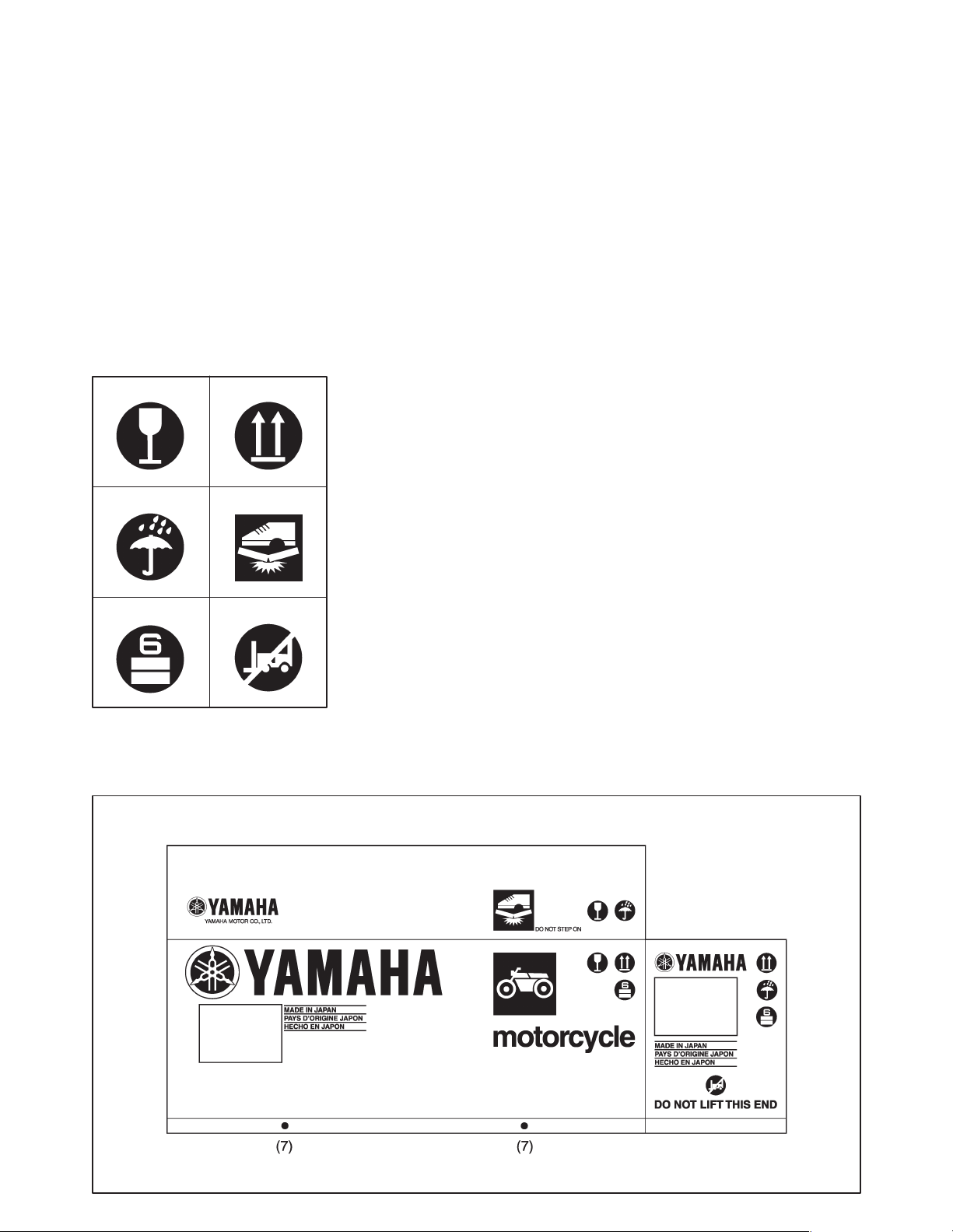
EAA00050
SYMBOLS USED ON
CRATE CARTON
(1) Contents of the transport package are
fragile, therefore the package must be
handled with care.
(2) Indicates correct upright position of the
transport package.
(3) Transport package must be kept away
from rain.
(4) Do not step anywhere on this carton box.
(5) Up to 6 of the transport packages can be
piled up.
(6) Insertion of the forklift arms from this
side can cause damage.
(7) Lift arm inserting position.
If the forklift arms cannot be inserted under
the transport package in alignment with the
two yellow labels, adjust the arms so that
they are positioned evenly in relation to
these marks while taking care not to damage the package contents.
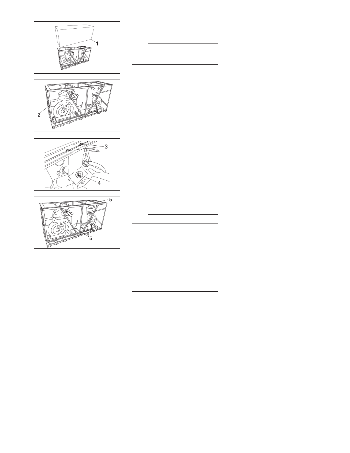
EAA00060
UNPACKING
1. Remove the frame cover (1).
NOTE:
To remove the frame cover, cut the vinyl
bands around the cover using a cutter or
scissors.
2. Remove the carton box (2).
3. Remove the packing frame bolts (3) and
steering stem nut (4).
4. Remove the packing frames (5). (Lift up
and then move to the side.)
NOTE:
Remove the bolts while holding the frame.
NOTE:
Before starting the assembly, check for
damaged or missing parts. Check both the
parts contained in the carton boxes and on
the vehicle for damage, scratches, and other defects.
–1–
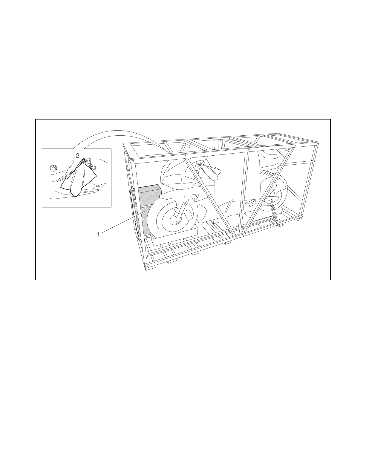
EAA00070
PARTS LOCATION
(1) Carton box
(2) Vinyl bag
–2–
7
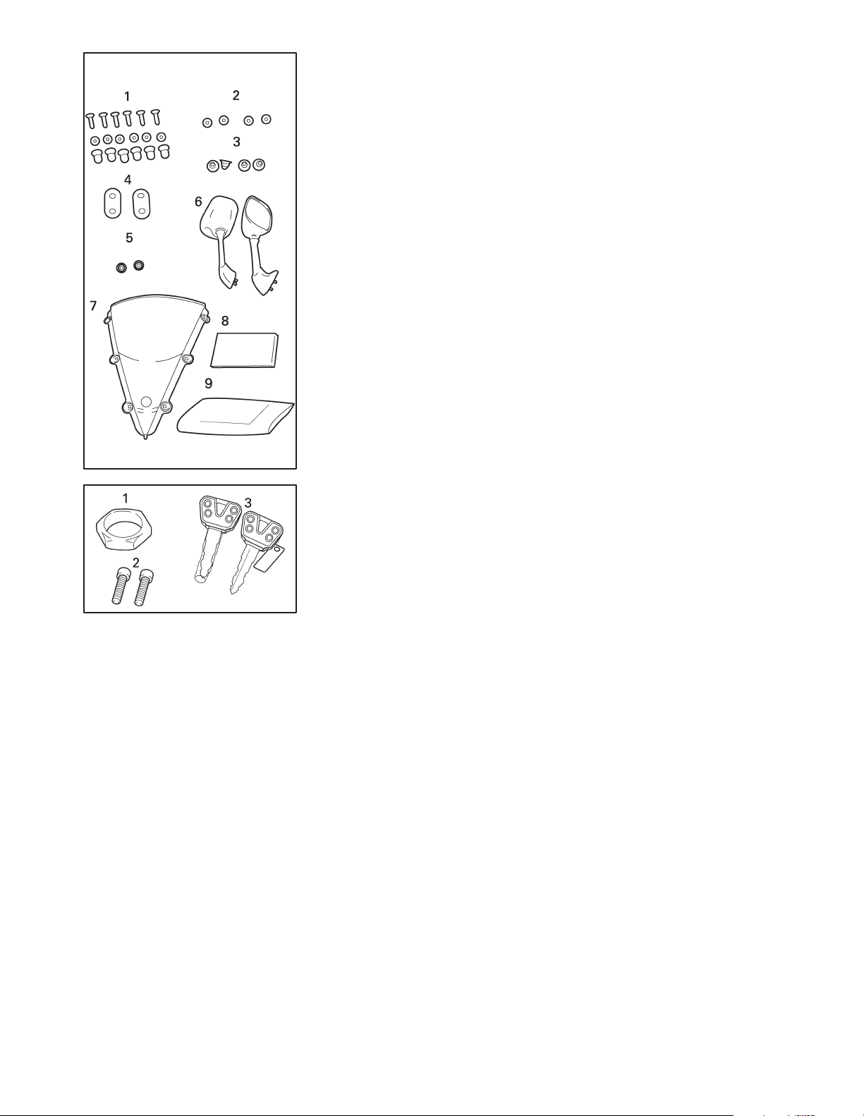
EAA00080
(1) Carton box
1. Screws, special nuts and washers
(windshield)
2. Collars
3. Nuts
4. Dampers
5. Plugs
6. Rear view mirrors
7. Windshield
8. Owner’s manual
9 Owner’s tool kit 2
(2) Vinyl bag
1. Steering steem nut
2. Handlebar bolts
3. Keys
–3–
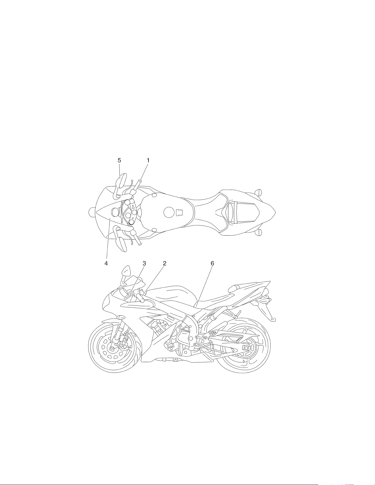
EAA00100
SETUP PROCEDURES
Perform the setup procedures in the order indicated by the numbers. Always follow the order as shown.
–4–
 Loading...