


SERVICE MANUAL
YZF-R1(B)
2012
1KB-28197-E0
Manuals by Motomatrix / www.motomatrix.co.uk / The Solution For Lost Motorcycle Coded Keys
email: info@motomatrix.co.uk

EAS20040
YZF-R1(B)
SERVICE MANUAL
©2011 by Yamaha Motor Co., Ltd.
First edition, July 2011
All rights reserved.
Any reproduction or unauthorized use
without the written permission of
Yamaha Motor Co., Ltd.
is expressly prohibited.
Manuals by Motomatrix / www.motomatrix.co.uk / The Solution For Lost Motorcycle Coded Keys
email: info@motomatrix.co.uk
EAS20071
IMPORTANT
This manual was produced by the Yamaha Motor Company, Ltd. primarily for use by Yamaha dealers and their qualified mechanics. It is not possible to include all the knowledge of a mechanic in one
manual. Therefore, anyone who uses this book to perform maintenance and repairs on Yamaha
vehicles should have a basic understanding of mechanics and the techniques to repair these types
of vehicles. Repair and maintenance work attempted by anyone without this knowledge is likely to
render the vehicle unsafe and unfit for use.
Yamaha Motor Company, Ltd. is continually striving to improve all of its models. Modifications and
significant changes in specifications or procedures will be forwarded to all authorized Yamaha dealers and will appear in future editions of this manual where applicable.
TIP
Designs and specifications are subject to change without notice.
EAS20081
IMPORTANT MANUAL INFORMATION
Particularly important information is distinguished in this manual by the following notations.
This is the safety alert symbol. It is used to alert you to potential personal injury hazards. Obey all safety messages that follow this symbol
to avoid possible injury or death.
A WARNING indicates a hazardous situation which, if not avoided,
could result in death or serious injury.
A NOTICE indicates special precautions that must be taken to avoid
damage to the vehicle or other property.
A TIP provides key information to make procedures easier or clearer.
WARNING
Manuals by Motomatrix / www.motomatrix.co.uk / The Solution For Lost Motorcycle Coded Keys
email: info@motomatrix.co.uk
EAS20090
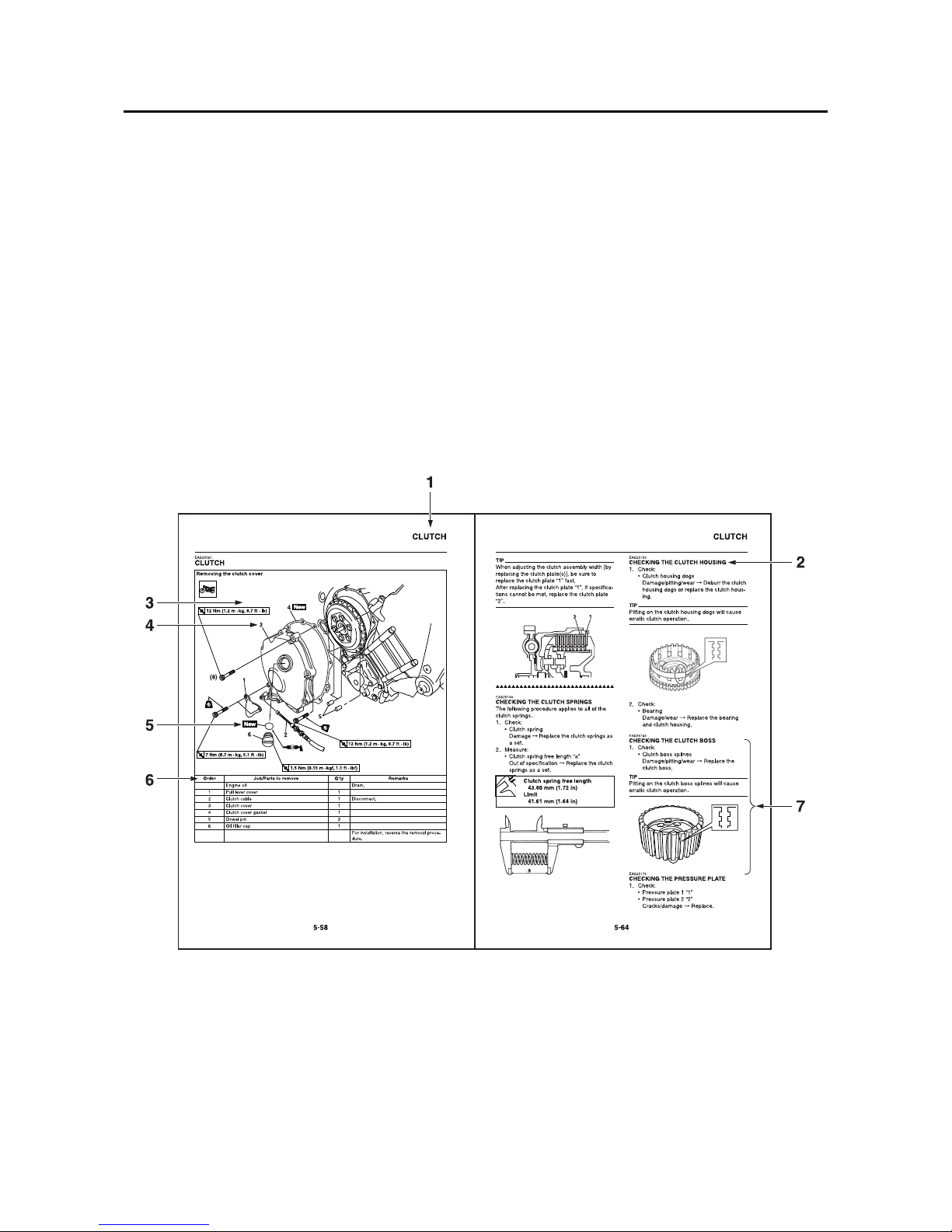
HOW TO USE THIS MANUAL
This manual is intended as a handy, easy-to-read reference book for the mechanic. Comprehensive
explanations of all installation, removal, disassembly, assembly, repair and check procedures are
laid out with the individual steps in sequential order.
• The manual is divided into chapters and each chapter is divided into sections. The current section
title “1” is shown at the top of each page.
• Sub-section titles “2” appear in smaller print than the section title.
• To help identify parts and clarify procedure steps, there are exploded diagrams “3” at the start of
each removal and disassembly section.
• Numbers “4” are given in the order of the jobs in the exploded diagram. A number indicates a disassembly step.
• Symbols “5” indicate parts to be lubricated or replaced.
Refer to “SYMBOLS”.
• A job instruction chart “6” accompanies the exploded diagram, providing the order of jobs, names
of parts, notes in jobs, etc.
• Jobs “7” requiring more information (such as special tools and technical data) are described
sequentially.
Manuals by Motomatrix / www.motomatrix.co.uk / The Solution For Lost Motorcycle Coded Keys
email: info@motomatrix.co.uk
EAS20100
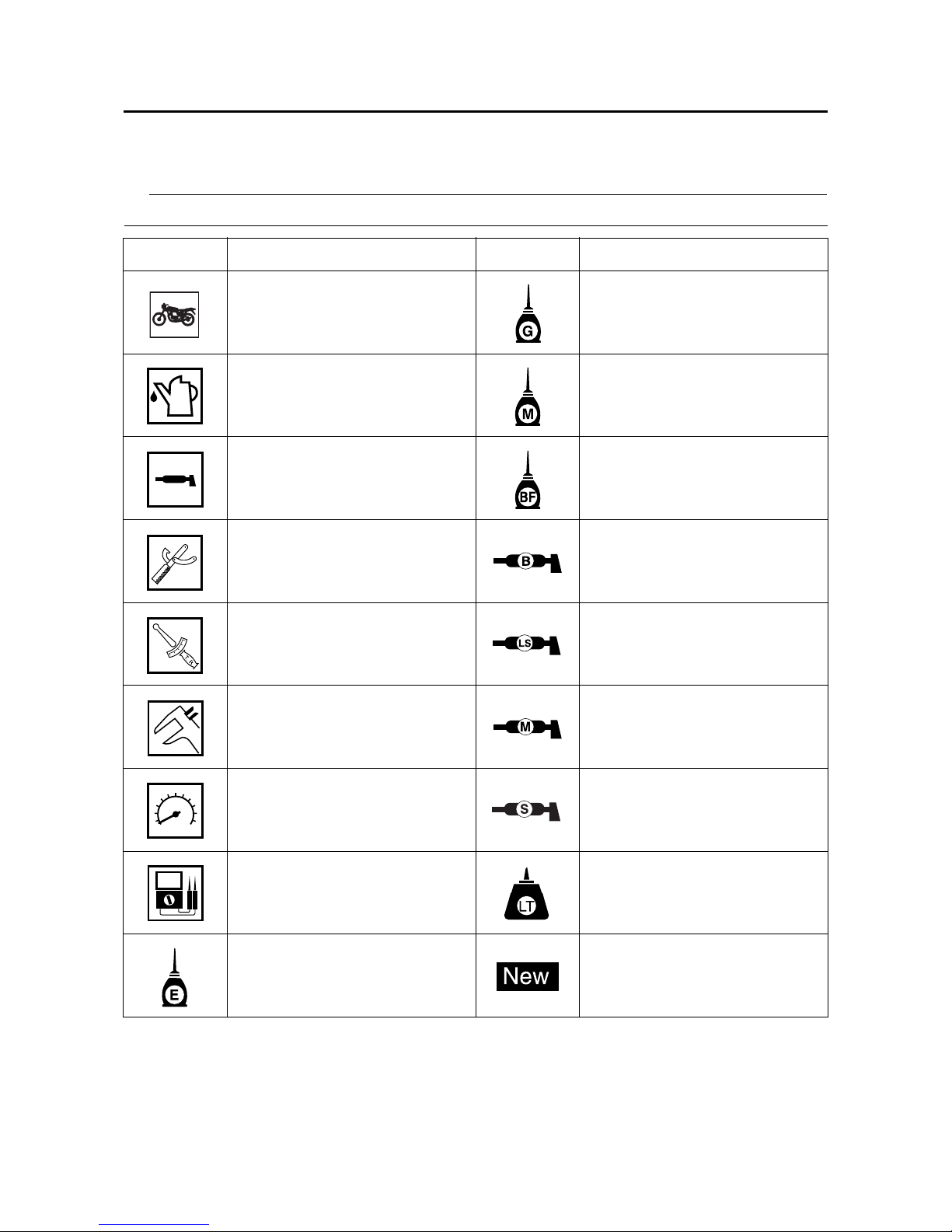
SYMBOLS
The following symbols are used in this manual for easier understanding.
TIP
The following symbols are not relevant to every vehicle.
SYMBOL DEFINITION SYMBOL DEFINITION
Serviceable with engine
mounted
Gear oil
Filling fluid Molybdenum disulfide oil
Lubricant Brake fluid
Special tool Wheel bearing grease
Tightening torque Lithium-soap-based grease
Wear limit, clearance Molybdenum disulfide grease
Engine speed Silicone grease
Electrical data
Apply locking agent
(LOCTITE®).
Engine oil
Replace the part with a new
one.
Manuals by Motomatrix / www.motomatrix.co.uk / The Solution For Lost Motorcycle Coded Keys
email: info@motomatrix.co.uk

Manuals by Motomatrix / www.motomatrix.co.uk / The Solution For Lost Motorcycle Coded Keys
email: info@motomatrix.co.uk

1
2
3
4
5
6
7
8
9
EAS20110
TABLE OF CONTENTS
GENERAL INFORMATION
SPECIFICATIONS
PERIODIC CHECKS AND ADJUSTMENTS
CHASSIS
ENGINE
COOLING SYSTEM
FUEL SYSTEM
ELECTRICAL SYSTEM
TROUBLESHOOTING
Manuals by Motomatrix / www.motomatrix.co.uk / The Solution For Lost Motorcycle Coded Keys
email: info@motomatrix.co.uk

Manuals by Motomatrix / www.motomatrix.co.uk / The Solution For Lost Motorcycle Coded Keys
email: info@motomatrix.co.uk

1
GENERAL INFORMATION
IDENTIFICATION ..........................................................................................1-1
VEHICLE IDENTIFICATION NUMBER...................................................1-1
MODEL LABEL.......................................................................................1-1
FEATURES ...................................................................................................1-2
OUTLINE OF THE FI SYSTEM ..............................................................1-2
FI SYSTEM.............................................................................................1-3
YCC-T (Yamaha Chip Controlled Throttle)
YCC-I (Yamaha Chip Controlled Intake) .................................................1-4
OUTLINE OF THE TCS (Traction Control System) ................................1-8
INSTRUMENT FUNCTIONS ................................................................1-12
IMPORTANT INFORMATION .....................................................................1-20
PREPARATION FOR REMOVAL AND DISASSEMBLY........................ 1-20
REPLACEMENT PARTS.......................................................................1-20
GASKETS, OIL SEALS AND O-RINGS................................................1-20
LOCK WASHERS/PLATES AND COTTER PINS .................................1-20
BEARINGS AND OIL SEALS ............................................................... 1-21
CIRCLIPS .............................................................................................1-21
CHECKING THE CONNECTIONS .............................................................1-22
HANDLING THE ELECTRONIC PARTS ....................................................1-23
SPECIAL TOOLS........................................................................................1-24
Manuals by Motomatrix / www.motomatrix.co.uk / The Solution For Lost Motorcycle Coded Keys
email: info@motomatrix.co.uk
IDENTIFICATION
1-1
EAS20130
IDENTIFICATION
EAS20140
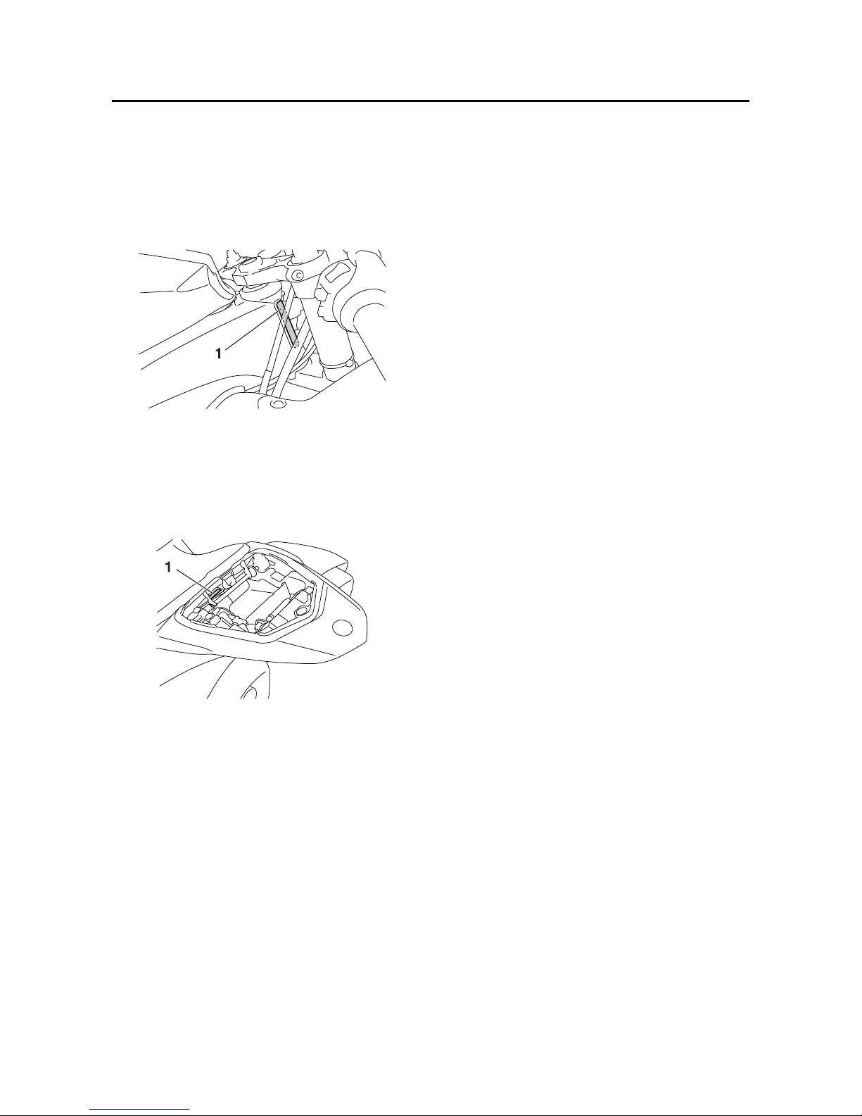
VEHICLE IDENTIFICATION NUMBER
The vehicle identification number “1” is
stamped into the right side of the steering
head pipe.
EAS20150
MODEL LABEL
The model label “1” is affixed to the seat rail
reinforcement under the passenger seat. This
information will be needed to order spare
parts.
Manuals by Motomatrix / www.motomatrix.co.uk / The Solution For Lost Motorcycle Coded Keys
email: info@motomatrix.co.uk
FEATURES
1-2
EAS20170
FEATURES
EAS30340
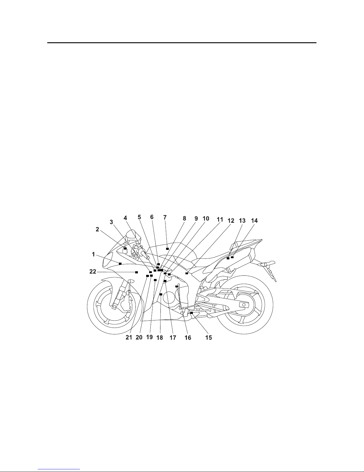
OUTLINE OF THE FI SYSTEM
The main function of a fuel supply system is to provide fuel to the combustion chamber at the optimum air-fuel ratio in accordance with the engine operating conditions and the atmospheric temperature. In the conventional carburetor system, the air-fuel ratio of the mixture that is supplied to the
combustion chamber is created by the volume of the intake air and the fuel that is metered by the jet
used in the respective carburetor.
Despite the same volume of intake air, the fuel volume requirement varies by the engine operating
conditions, such as acceleration, deceleration, or operating under a heavy load. Carburetors that
meter the fuel through the use of jets have been provided with various auxiliary devices, so that an
optimum air-fuel ratio can be achieved to accommodate the constant changes in the operating conditions of the engine.
As the requirements for the engine to deliver more performance and cleaner exhaust gases
increase, it becomes necessary to control the air-fuel ratio in a more precise and finely tuned manner. To accommodate this need, this model has adopted an electronically controlled fuel injection
(FI) system, in place of the conventional carburetor system. This system can achieve an optimum
air-fuel ratio required by the engine at all times by using a microprocessor that regulates the fuel
injection volume according to the engine operating conditions detected by various sensors.
The adoption of the FI system has resulted in a highly precise fuel supply, improved engine
response, better fuel economy, and reduced exhaust emissions.
1. Intake air temperature sensor
2. Engine trouble warning light
3. Air induction system solenoid
4. Atmospheric pressure sensor
5. Intake air pressure sensor
6. Intake funnel servo motor
7. Secondary injectors
8. Throttle servo motor
9. Throttle position sensor
10.Accelerator position sensor
11.Primary injectors
12.Fuel pump
13.Lean angle sensor
14.Relay unit (fuel pump relay)
15.O
2
sensor
16.Rear speed sensor
17.Coolant temperature sensor
18.Crankshaft position sensor
19.Spark plugs
20.Ignition coils
21.Cylinder identification sensor
22.ECU (engine control unit)
Manuals by Motomatrix / www.motomatrix.co.uk / The Solution For Lost Motorcycle Coded Keys
email: info@motomatrix.co.uk
FEATURES
1-3
EAS14B1017
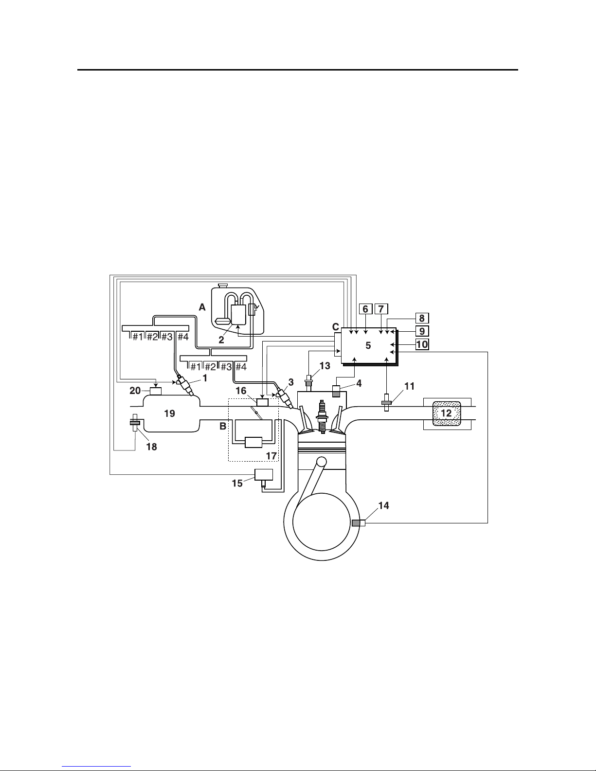
FI SYSTEM
The fuel pump delivers fuel to the fuel injector via the fuel filter. The pressure regulator maintains the
fuel pressure that is applied to the fuel injector at a certain level. Accordingly, when the energizing
signal from the ECU energizes the fuel injector, the fuel passage opens, causing the fuel to be
injected into the intake manifold only during the time the passage remains open. Therefore, the
longer the length of time the fuel injector is energized (injection duration), the greater the volume of
fuel that is supplied. Conversely, the shorter the length of time the fuel injector is energized (injection
duration), the lesser the volume of fuel that is supplied.
The injection duration and the injection timing are controlled by the ECU. Signals that are input from
the throttle position sensor, accelerator position sensor, coolant temperature sensor, atmospheric
pressure sensor, cylinder identification sensor, lean angle sensor, crankshaft position sensor, intake
air pressure sensor, air temperature sensor, rear speed sensor and O
2
sensor enable the ECU to
determine the injection duration. The injection timing is determined through the signals from the
crankshaft position sensor and cylinder identification sensor. As a result, the volume of fuel that is
required by the engine can be supplied at all times in accordance with the driving conditions.
1. Secondary injector
2. Fuel pump
3. Primary injector
4. Cylinder identification sensor
5. ECU (engine control unit)
6. Throttle position sensor
7. Accelerator position sensor
8. Rear speed sensor
9. Intake air temperature sensor
10.Lean angle sensor
11.O
2
sensor
12.Catalytic converter
13.Coolant temperature sensor
14.Crankshaft position sensor
15.Intake air pressure sensor
16.Throttle servo motor
17.Throttle body
18.Atmospheric pressure sensor
19.Air filter case
20.Intake funnel servo motor
A. Fuel system
B. Air system
C. Control system
Manuals by Motomatrix / www.motomatrix.co.uk / The Solution For Lost Motorcycle Coded Keys
email: info@motomatrix.co.uk

FEATURES
1-4
EAS14B1076
YCC-T (Yamaha Chip Controlled Throttle) YCC-I (Yamaha Chip Controlled Intake)
Mechanism characteristics
Yamaha developed the YCC-T and YCC-I system employing the most advanced electronic control
technologies. Electronic control throttle systems have been used on automobiles, but Yamaha has
developed a faster, more compact system specifically for the needs of a sports motorcycle. The
Yamaha-developed system has a high-speed calculating capacity that produces computations of
running conditions every 1/1000th of a second.
The YCC-T system is designed to respond to the throttle action of the rider by having the ECU
instantaneously calculate the ideal throttle valve opening and generate signals to operate the motordriven throttle valves and thus actively control the intake air volume.
The ECU contains three CPUs with a capacity about five times that of conventional units, making it
possible for the system to respond extremely quickly to the slightest adjustments made by the rider.
In particular, optimized control of the throttle valve opening provides the optimum volume of intake
air for easy-to-use torque, even in a high-revving engine.
The YCC-I system calculates the value from the engine speed and throttle opening rate, activates
the intake air funnel with the electronic control motor drive to control the intake pipe length in order
to gain the high power output in all revolution ranges from low speeds to high speeds.
Aims and advantages of using YCC-T system
• Increased engine power
By shortening the air intake path, higher engine speed is possible → Increased engine power.
• Improved driveability
Air intake volume is controlled according to the operating conditions → Improved throttle response
to meet engine requirement.
Driving force is controlled at the optimal level according to the transmission gear position and
engine speed → Improved throttle control.
• Engine braking control
Due to the throttle control, optimal engine braking is made possible.
• Simplified idle speed control (ISC) mechanism
The bypass mechanism and ISC actuator are eliminated → A simple mechanism is used to maintain a steady idle speed.
• Reduced weight
Compared to using a sub-throttle mechanism, weight is reduced.
1. Throttle servo motor
2. Accelerator position sensor
3. Throttle cable pulley with linkage guard
4. Throttle valves
5. Throttle position sensor
A. To throttle grip
Manuals by Motomatrix / www.motomatrix.co.uk / The Solution For Lost Motorcycle Coded Keys
email: info@motomatrix.co.uk
FEATURES
1-5
Aims and advantages of using YCC-I system
• Improved power band
By using a dual intake funnel system, YCC-I optimizes the effectiveness of the fuel injection system to deliver an incredibly precise air/fuel mixture to the combustion chamber. This degree of
intake volume control gives both improved low to mid-range power, as well as improved power in
the higher rpm range. In effect, the YCC-I offers higher levels of power across the RPM range.
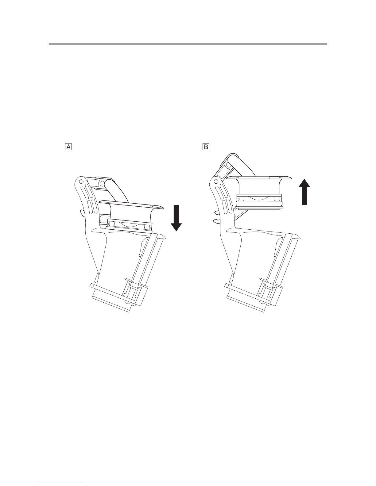
• Electronically controlled intake length
The YCC-I system consists of four lightweight plastic resin funnels, and each of these is divided
into an upper and lower portion. Depending upon operating conditions, the funnels can be joined
to form a single long funnel, or split to create a short funnel. This change is performed instantaneously by an electrically controlled servo-motor which handles the function so smoothly that the
rider is unaware it is happening.
A. Down position (long intake)
(Low rpm to Mid rpm)
B. Up position (short intake)
(High rpm)
Manuals by Motomatrix / www.motomatrix.co.uk / The Solution For Lost Motorcycle Coded Keys
email: info@motomatrix.co.uk
FEATURES
1-6
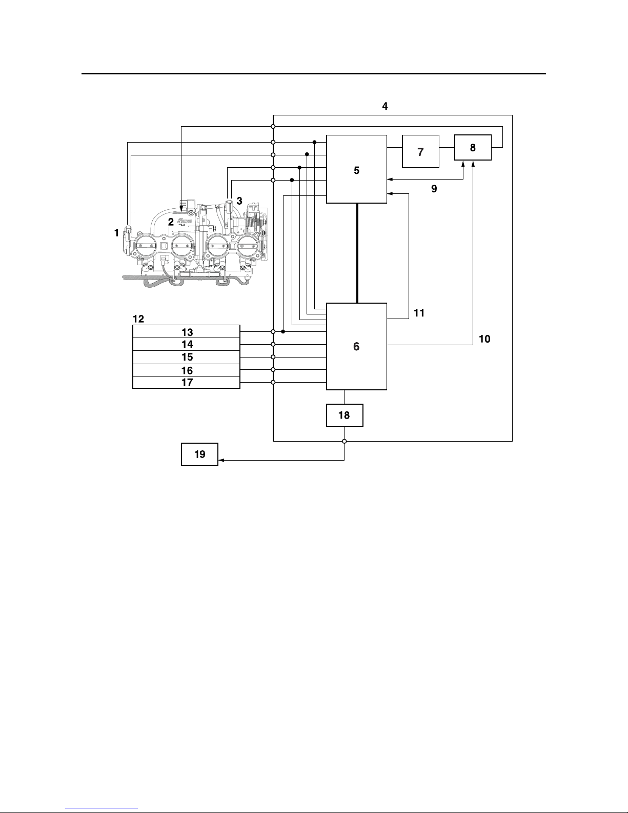
YCC-T/YCC-I system outline
1. Throttle position sensor
2. Throttle servo motor
3. Accelerator position sensor
4. ECU (engine control unit)
5. ETV main CPU (32 bit)
6. FI CPU (32 bit)
7. Throttle servo motor driver
8. Throttle servo motor driver operation sensing/shut off circuit
9. Throttle servo motor driver operation sensing feedback/emergency stop
10.Emergency stop
11.Engine revolution (pulse signal)
12.Sensor input
13.Neutral switch
14.Crankshaft position sensor
15.Rear speed sensor
16.Coolant temperature sensor
17.Atmospheric pressure sensor
18.Intake funnel servo motor driver
19.Intake funnel servo motor
Manuals by Motomatrix / www.motomatrix.co.uk / The Solution For Lost Motorcycle Coded Keys
email: info@motomatrix.co.uk

FEATURES
1-7
YCC-T/YCC-I control outline
1. Accelerator position sensor
2. Throttle position sensor
3. Crankshaft position sensor
4. Rear speed sensor
5. D-mode switch
6. Coolant temperature sensor
7. Neutral switch
8. Atmospheric pressure sensor
9. Accelerator position (two signals)
10.Throttle position (two signals)
11.Engine revolution
12.Vehicle speed
13.Coolant temperature
14.Neutral/In gear
15.Atmospheric pressure
16.Throttle servo motor
17.ECU (engine control unit)
18.Base map
19.Idle speed control
20.Calculated throttle valve opening angle
21.Base map
22.Air funnel position (Calculation value)
23.Intake funnel servo motor
Manuals by Motomatrix / www.motomatrix.co.uk / The Solution For Lost Motorcycle Coded Keys
email: info@motomatrix.co.uk
FEATURES
1-8
EAS1KB8101
OUTLINE OF THE TCS (Traction Control System)
The traction control system controls excessive spinning (slipping) of the rear wheel when accelerating.
The ECU monitors the front and rear wheel speeds using the signals from the front and rear speed
sensors, and detects rear wheel slipping according to the difference between the wheel speeds. If
the slipping exceeds the preset value, the ECU controls the slipping using integrated control of the
ignition timing, fuel cut-off, and throttle valve opening of the YCC-T system.
The traction control system can be set to one of six traction control system modes and an off mode.
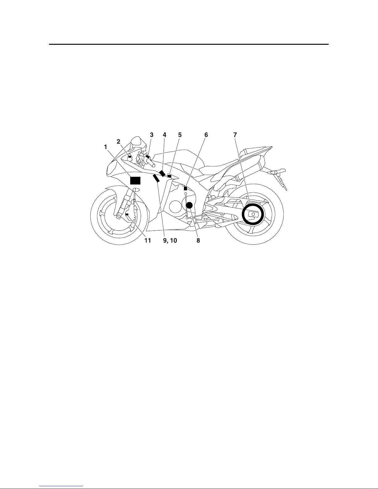
TCS (Traction control system) layout
1. ECU (engine control unit)
2. Traction control system indicator/warning
light
3. Traction control system switch
4. Throttle servo motor
5. Fuel injector
6. Rear speed sensor
7. Rear wheel sprocket
8. Drive sprocket
9. Ignition coils
10.Spark plugs
11.Front speed sensor
Manuals by Motomatrix / www.motomatrix.co.uk / The Solution For Lost Motorcycle Coded Keys
email: info@motomatrix.co.uk

FEATURES
1-9
TCS (Traction control system) block diagram
The signals from the front and rear speed sensors are sent to the ECU, and the ECU calculates the
amount of slip according to the difference between the detected front and rear wheel speeds.
If the amount of slip exceeds the preset value, the ECU controls the ignition timing, fuel cut-off, and
throttle valve opening of the YCC-T system so that the amount of slip is less than the preset value.
The traction control system indicator/warning light in the meter assembly flashes when the traction
control system has activated.
TCS (Traction control system) function
The traction control system helps maintain traction when accelerating. If sensors detect that the rear
wheel is starting to slip (uncontrolled spinning), the traction control system assists by regulating
engine power as needed until traction is restored. The traction control system indicator/warning light
flashes to let the rider know that traction control has engaged.
WARNING
EWA23P1039
The traction control system is not a substitute for riding appropriately for the conditions.
Traction control cannot prevent loss of traction due to excessive speed when entering turns,
when accelerating hard at a sharp lean angle, or while braking, and cannot prevent front
wheel slipping. As with any motorcycle, approach surfaces that may be slippery with caution
and avoid especially slippery surfaces.
TIP
• The traction control may engage when the vehicle travels over a bump.
• The rider may notice slight changes in engine and exhaust sounds when the traction control system is engaged.
1. Front speed sensor
2. Rear speed sensor
3. Traction control system switch
4. ECU (engine control unit)
A. Slip amount calculation
B. Exceeds preset value
C. Actuator control
D. Fuel cut-off
E. Ignition timing (retarded)
F. Traction control system indicator/warning
light (flashes)
G. YCC-T motor throttle valve opening
(decreased)
Manuals by Motomatrix / www.motomatrix.co.uk / The Solution For Lost Motorcycle Coded Keys
email: info@motomatrix.co.uk
FEATURES
1-10
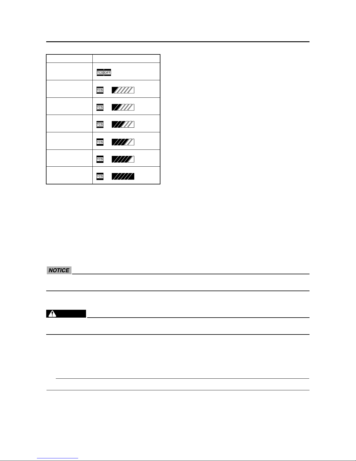
There are six traction control system modes and an off mode.
• “TCS” mode 1 provides for the least traction control system assist.
• “TCS” modes 2 through 6 provide for more traction control system assist. Mode 6 provides the
most traction control system assist.
• “TCS OFF” mode turns the traction control system off. The system may also be automatically disabled in some riding conditions.
When the key is turned to “ON”, the traction control system is enabled and the last mode selected
displays in the multi-function meter.
All traction control system modes can be selected when the key is in the “ON” position. Modes 1
through 6 can also be selected when the vehicle is moving, however the throttle grip must be completely closed. The traction control system cannot be turned on or off while the vehicle is moving.
ECA23P1085
Use only the specified tires. Using different sized tires will prevent the traction control system from controlling tire rotation accurately.
Setting the traction control system
WARNING
EWA1KB8101
Changing settings while riding can distract the operator. Therefore, take extra precaution
when changing modes while riding.
When the vehicle is stopped, push the upper side of the traction control system switch for at least
two seconds to turn the traction control system off. Push the lower side of the switch to turn the traction control system on. When the vehicle is stopped or while riding, close the throttle and push the
lower side of the switch to change from modes 1 to 6. Close the throttle and push the upper side of
the switch to change from modes 6 to 1.
TIP
The vehicle was set to “TCS” mode 6 at the time of manufacture.
Display
OFF
Mode 1
Mode 2
Mode 3
Mode 4
Mode 5
Mode 6
Manuals by Motomatrix / www.motomatrix.co.uk / The Solution For Lost Motorcycle Coded Keys
email: info@motomatrix.co.uk

FEATURES
1-11
Resetting
The traction control system may be disabled in the following conditions:
• Either the front wheel or rear wheel comes off the ground while riding
• Excessive rear wheel spinning
If the traction control system has been disabled, both the traction control system indicator/warning
light and the engine trouble warning light come on.
To reset the traction control system:
Turn the key to “OFF”. Wait at least one second, then turn the key back to “ON”. The traction control
system indicator/warning light should go off and the system will be enabled. The engine trouble
warning light should go off after the motorcycle reaches at least 20 km/h (12 mi/h). If the traction
control system indicator/warning light and/or engine trouble warning light still remain on after resetting, check the fuel injection system (Refer to “FUEL INJECTION SYSTEM” on page 8-33).
ECA1KB8101
• Keep any type of magnets (including magnetic pick-up tools, magnetic screwdrivers, etc.)
away from the front and rear speed sensor or front speed sensor rotor; otherwise, the sensors or rotor may be damaged, resulting in improper performance of the traction control
system.
• Be careful not to damage the sensors or rotor.
1. Traction control system switch
2. Traction control system mode display
Manuals by Motomatrix / www.motomatrix.co.uk / The Solution For Lost Motorcycle Coded Keys
email: info@motomatrix.co.uk

FEATURES
1-12
EAS1KB8102
INSTRUMENT FUNCTIONS
Multi-function meter unit
WARNING
EWA14B1014
Be sure to stop the vehicle before making
any setting changes to the multi-function
meter unit. Changing settings while riding
can distract the operator and increase the
risk of an accident.
The multi-function meter unit is equipped with
the following:
• A speedometer
• A tachometer
• An odometer
• Two tripmeters (which show the distance
traveled since they were last set to zero)
• A fuel reserve tripmeter (which shows the
distance traveled since the fuel level warning
light came on)
• A stopwatch
•A clock
• A coolant temperature display
• An air intake temperature display
• A transmission gear display
• A drive mode display (which shows the
selected drive mode)
• A fuel consumption display (instantaneous
and average consumption functions)
• A traction control system mode display
(which shows the selected traction control
system mode)
• A self-diagnosis device
• A display brightness and shift timing indicator
light control mode
TIP
• Be sure to turn the key to “ON” before using
the “SELECT” and “RESET” buttons, except
for setting the display brightness and shift
timing indicator light control mode.
• For the U.K. only: To switch the speedometer
and odometer/tripmeter/fuel consumption
displays between kilometers and miles,
press the “SELECT” button for at least one
second.
Tachometer
The electric tachometer allows the rider to
monitor the engine speed and keep it within
the ideal power range.
When the key is turned to “ON”, the tachometer needle sweeps once across the r/min range
and then returns to zero r/min in order to test
the electrical circuit.
ECA14B1015
Do not operate the engine in the tachometer red zone.
Red zone: 13750 r/min and above
1. “RESET” button
2. “SELECT” button
3. Tachometer
4. Shift timing indicator light
5. Traction control system mode display
6. Coolant temperature display/air intake temperature display
7. Drive mode display
8. Speedometer
9. Odometer/tripmeter/fuel reserve tripmeter/
instantaneous fuel consumption display/
average fuel consumption display
10.Clock/stopwatch
11.Transmission gear display
1. Tachometer
2. Tachometer red zone
Manuals by Motomatrix / www.motomatrix.co.uk / The Solution For Lost Motorcycle Coded Keys
email: info@motomatrix.co.uk
FEATURES
1-13
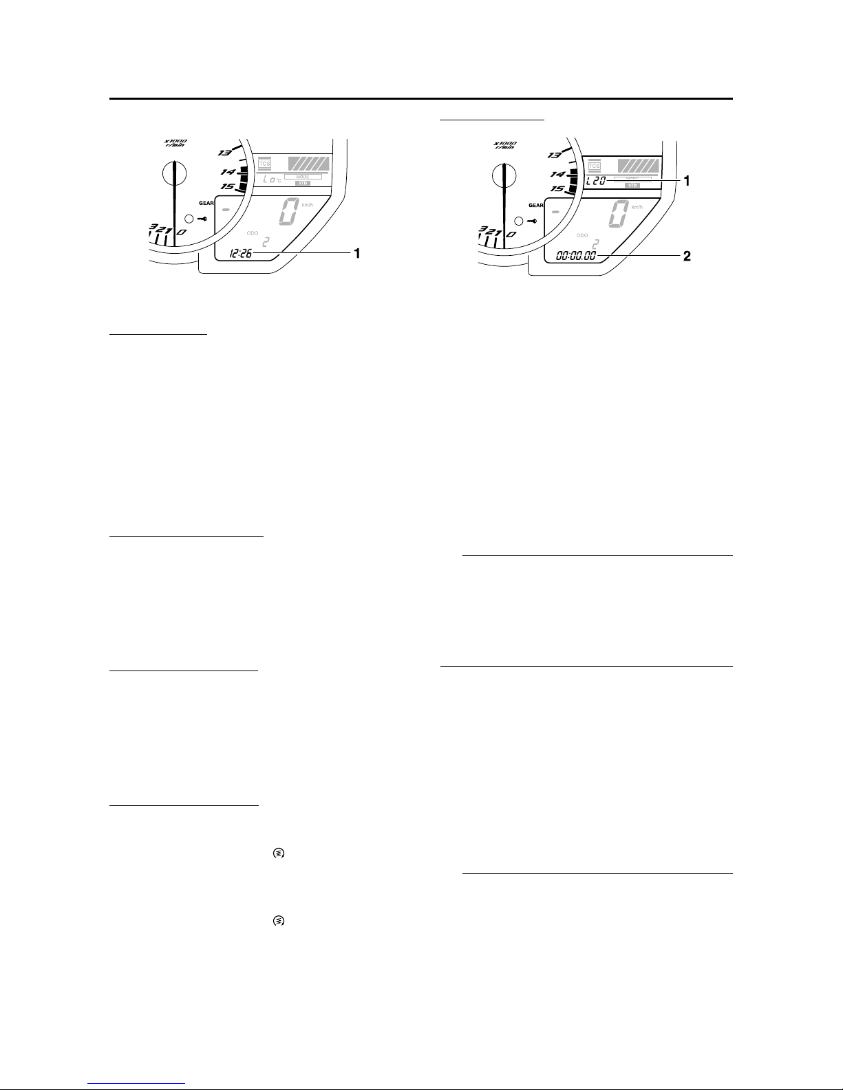
Clock and stopwatch modes
To set the clock
1. Push the “SELECT” button and “RESET”
button together for at least two seconds.
2. When the hour digits start flashing, push
the “RESET” button to set the hours.
3. Push the “SELECT” button, and the minute
digits start flashing.
4. Push the “RESET” button to set the minutes.
5. Push the “SELECT” button and then
release it to start the clock.
To display the stopwatch
To change the display to the stopwatch mode,
push the “SELECT” button and “RESET” button together. To change the display back to the
clock mode, push the “SELECT” button and
“RESET” button together; however, this is not
possible when the stopwatch is counting.
Standard measurement
1. Push the “RESET” button to start the stopwatch.
2. Push the “SELECT” button to stop the stopwatch.
3. Push the “SELECT” button again to reset
the stopwatch.
Split time measurement
1. Push the “RESET” button to start the stopwatch.
2. Push the start switch “ ” or “RESET” button to measure split times. Split times are
displayed on the odometer display for five
seconds.
3. Push the start switch “ ” or “RESET” button to display the final split time or push the
“SELECT” button to stop the stopwatch and
display the final split time.
Split time history
The split time history displays up to 20 stored
split times. The split time history can be displayed either in reverse chronological order or
by speed.
1. Push the “SELECT” button for at least one
second to select the reverse chronological
order mode; “L20” displays on the stopwatch.
Push the “SELECT” button again to select
the speed mode; “F20” displays on the
stopwatch.
TIP
• Reverse chronological order mode: The split
times are shown from the latest to earliest
(i.e., L1, L2, L3, L4).
• Speed order mode: The split times are
shown from the fastest to slowest (i.e., F1,
F2, F3, F4).
2. Push the “RESET” button. Depending on
the selected split time, “L1” or “F1” displays
on the coolant temperature display/air
intake temperature display, and its corresponding stored split time displays on the
stopwatch.
3. Push the “SELECT” button to switch the
displayed split time in ascending order (i.e.,
1, 2, 3, 4), and the “RESET” button to
switch the displayed split time in descending order (i.e., 20, 19, 18, 17).
TIP
• To switch between the reverse chronological
order mode and the speed mode, push the
“SELECT” button for at least one second to
cancel the currently selected mode, and then
repeat step 1 to select the desired mode.
1. Clock/stopwatch
1. Coolant temperature display/air intake temperature display
2. Stopwatch
Manuals by Motomatrix / www.motomatrix.co.uk / The Solution For Lost Motorcycle Coded Keys
email: info@motomatrix.co.uk

FEATURES
1-14
• To reset all the recorded times for the
selected split time history, push the “RESET”
button for at least one second.
4. Push the “SELECT” button for at least one
second to cancel the split time history and
return to the time measurement.
Odometer, tripmeter, instantaneous fuel
consumption and average fuel consumption modes
Push the “SELECT” button to switch the display between the odometer mode “ODO”, the
tripmeter modes “TRIP 1” and “TRIP 2”, the
instantaneous fuel consumption mode “km/L”
or “L/100 km”, and the average fuel consumption mode “AVE_ _._ km/L” or “AVE_ _._ L/100
km” in the following order:
ODO → TRIP 1 → TRIP 2 → km/L or L/100 km
→ AVE_ _._ km/L or AVE_ _._ L/100 km →
ODO
For the UK only:
Push the “SELECT” button to switch the display between the odometer mode “ODO”, the
tripmeter modes “TRIP 1” and “TRIP 2”, the
instantaneous fuel consumption mode “km/L”,
“L/100 km” or “MPG”, and the average fuel
consumption mode “AVE_ _._ km/L”, “AVE_
_._ L/100 km” or “AVE_ _._ MPG” in the following order:
ODO → TRIP 1 → TRIP 2 → km/L, L/100 km
or MPG → AVE_ _._ km/L, AVE_ _._ L/100 km
or AVE_ _._ MPG → ODO
If the fuel level warning light comes on, the display automatically changes to the fuel reserve
tripmeter mode “TRIP F” and starts counting
the distance traveled from that point. In that
case, push the “SELECT” button to switch the
display between the various tripmeter, odometer, instantaneous fuel consumption and average fuel consumption modes in the following
order:
TRIP F → km/L or L/100 km → AVE_ _._ km/L
or AVE_ _._ L/100 km → ODO → TRIP 1 →
TRIP 2 → TRIP F
For the UK only:
TRIP F → km/L, L/100 km or MPG → AVE_
_._ km/L, AVE_ _._ L/100 km or AVE_ _._
MPG → ODO → TRIP 1 → TRIP 2 → TRIP F
To reset a tripmeter, select it by pushing the
“SELECT” button, and then push the “RESET”
button for at least one second.
If you do not reset the fuel reserve tripmeter
manually, it resets itself automatically and the
display returns to the prior mode after refueling
and traveling 5 km (3 mi).
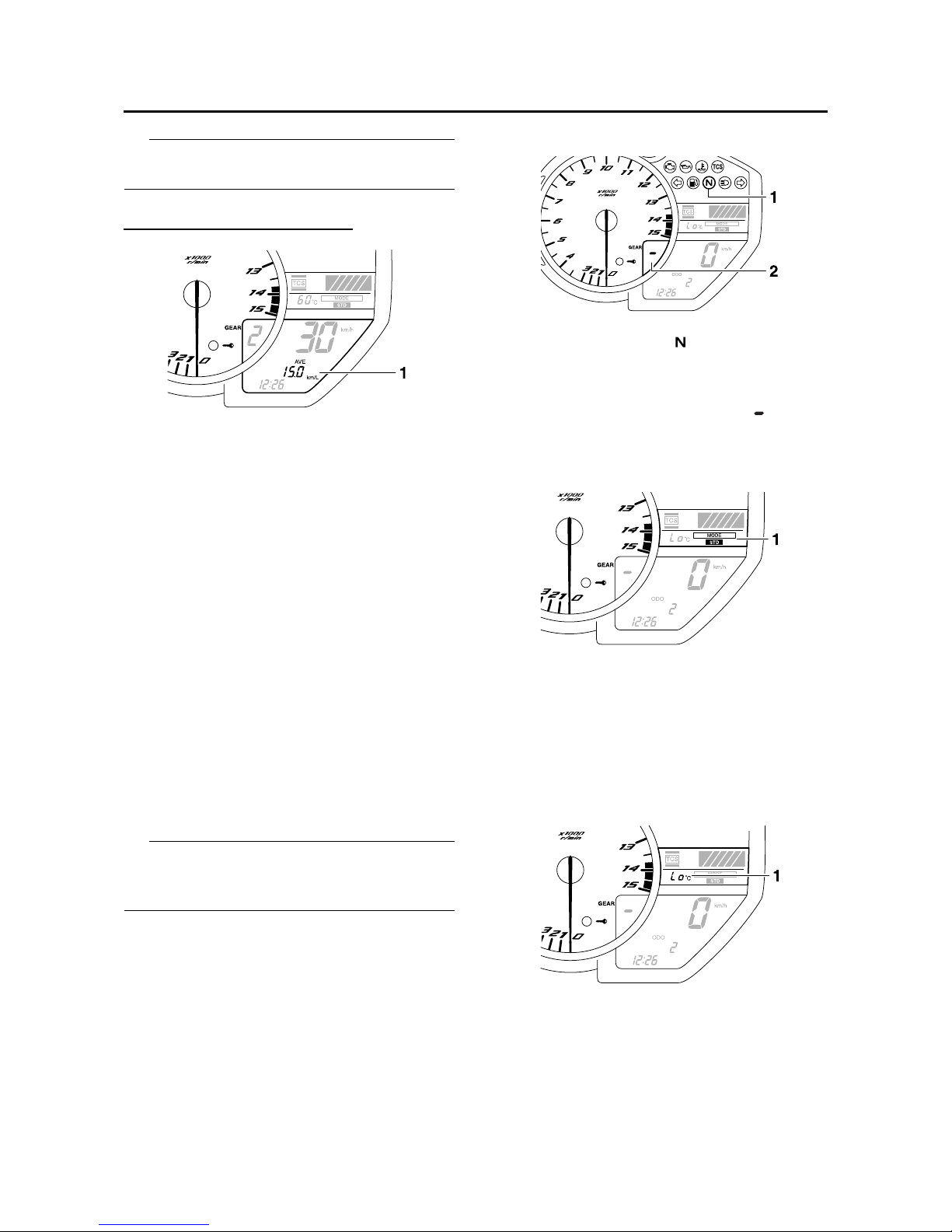
Instantaneous fuel consumption mode
The instantaneous fuel consumption display
can be set to either “km/L”, “L/100 km” or
“MPG” (for the UK only).
• “km/L”: The distance that can be traveled on
1.0 L of fuel under the current riding conditions is shown.
• “L/100 km”: The amount of fuel necessary to
travel 100 km under the current riding conditions is shown.
• “MPG” (for the UK only): The distance that
can be traveled on 1.0 Imp.gal of fuel under
the current riding conditions is shown.
To switch between the instantaneous fuel consumption displays, push the “SELECT” button
for one second when one of the displays is
shown.
1. Odometer/tripmeter/fuel reserve tripmeter/
instantaneous fuel consumption display/
average fuel consumption display
1. Instantaneous fuel consumption display
Manuals by Motomatrix / www.motomatrix.co.uk / The Solution For Lost Motorcycle Coded Keys
email: info@motomatrix.co.uk
FEATURES
1-15
TIP
If traveling at speeds under 10 km/h (6.0 mi/h),
“_ _._” is displayed.
Average fuel consumption mode
The average fuel consumption display can be
set to either “AVE_ _._ km/L”, “AVE_ _._ L/100
km” or “AVE_ _._ MPG” (for the UK only).
This display shows the average fuel consumption since it was last reset.
• “AVE_ _._ km/L”: The average distance that
can be traveled on 1.0 L of fuel is shown.
• “AVE_ _._ L/100 km”: The average amount of
fuel necessary to travel 100 km is shown.
• “AVE_ _._ MPG” (for the UK only): The average distance that can be traveled on 1.0
Imp.gal of fuel is shown.
To switch between the average fuel consumption displays, push the “SELECT” button for
one second when one of the displays is shown.
To reset the average fuel consumption display,
select it by pushing the “SELECT” button, and
then push the “RESET” button for at least one
second.
TIP
After resetting an average fuel consumption
display, “_ _._” is shown for that display until
the vehicle has traveled 1 km (0.6 mi).
Transmission gear display
This display shows the selected gear.
The neutral position is indicated by “ ” and by
the neutral indicator light.
Drive mode display
This display indicates which drive mode has
been selected: “STD”, “A” or “B”.
For more details on the modes and on how to
select them, refer to “D-mode (drive mode)”.
Coolant temperature display
The coolant temperature display indicates the
temperature of the coolant.
1. Average fuel consumption display
1. Neutral indicator light “ ”
2. Transmission gear display
1. Drive mode display
1. Coolant temperature display
Manuals by Motomatrix / www.motomatrix.co.uk / The Solution For Lost Motorcycle Coded Keys
email: info@motomatrix.co.uk

FEATURES
1-16
TIP
When the coolant temperature display is
selected, “C” is displayed for one second, and
then the coolant temperature is displayed.
ECA14B1016
Do not continue to operate the engine if it is
overheating.
Air intake temperature display
The air intake temperature display indicates
the temperature of the air drawn into the air filter case. Turn the key to “ON”, and push the
“RESET” button to switch the coolant temperature display to the air intake temperature display. Push the “RESET” button again to return
to the coolant temperature display.
TIP
• Even if the air intake temperature is set to be
displayed, the coolant temperature warning
light comes on if the engine overheats.
• When the key is turned to “ON”, the coolant
temperature is automatically displayed, even
if the air intake temperature was displayed
prior to turning the key to “OFF”.
• When the air intake temperature display is
selected, “A” is displayed before the temperature.
Traction control system mode display
This display indicates which traction control
system mode has been selected. For more
details on the modes and on how to select
them, refer to “TCS (Traction control system)
function”.
Self-diagnosis device
This model is equipped with a self-diagnosis
device for various electrical circuits.
If a problem is detected in the immobilizer system circuits, the immobilizer system indicator
light flashes and the display indicates an error
code.
If a problem is detected in any other circuit, the
engine trouble warning light comes on and the
display indicates an error code.
If the display indicates any error codes, note
the code number, and check the fuel injection
system (Refer to “FUEL INJECTION SYSTEM”
on page 8-33).
TIP
If the display indicates immobilizer system circuit error code 52, this could be caused by
transponder interference. If this error code
appears, try following the procedure below.
1. Air intake temperature display
1. Traction control system mode display
1. Error code display
Manuals by Motomatrix / www.motomatrix.co.uk / The Solution For Lost Motorcycle Coded Keys
email: info@motomatrix.co.uk

FEATURES
1-17
1. Use the code re-registering key to start the
engine.
TIP
Make sure there are no other immobilizer keys
close to the main switch, and do not keep more
than one immobilizer key on the same key ring!
Immobilizer system keys may cause signal
interference, which may prevent the engine
from starting.
2. If the engine starts, turn it off and try start-
ing the engine with the standard keys.
3. If one or both of the standard keys do not
start the engine, check the immobilizer system (Refer to “IMMOBILIZER SYSTEM” on
page 8-111).
ECA14B1017
If the display indicates an error code, the
vehicle should be checked as soon as possible in order to avoid engine damage.
Display brightness and shift timing indicator light control mode
This mode allows you to make changes to five
settings by performing the following steps.
1. Turn the key to “OFF”.
2. Push and hold the “SELECT” button.
3. Turn the key to “ON”, and then release the
“SELECT” button after five seconds. The
display brightness function is selected.
4. Push the “SELECT” button to switch the
functions in the order below.
a. Display brightness:
This function allows you to adjust the
brightness of the displays and tachometer to suit the outside lighting conditions.
b. Shift timing indicator light activity:
This function allows you to choose
whether or not the indicator light should
be activated and whether it should flash
or stay on when activated.
c. Shift timing indicator light activation:
This function allows you to select the
engine speed at which the indicator
light is activated.
d. Shift timing indicator light deactivation:
This function allows you to select the
engine speed at which the indicator
light is deactivated.
e. Shift timing indicator light brightness:
This function allows you to adjust the
brightness of the indicator light to suit
your preference.
TIP
The display shows the current setting for each
function, except the shift timing indicator light
activity function.
To adjust the brightness of the multifunction
meter displays and tachometer
1. Turn the key to “OFF”.
2. Push and hold the “SELECT” button.
3. Turn the key to “ON”, and then release the
“SELECT” button after five seconds.
4. Push the “RESET” button to select the
desired brightness level.
5. Push the “SELECT” button to confirm the
selected brightness level. The control
mode changes to the shift timing indicator
light activity function.
To set the shift timing indicator light activity
function
1. Push the “RESET” button to select one of
the following indicator light activity settings:
• The indicator light stays on when acti-
vated. (This setting is selected when the
indicator light stays on.)
• The indicator light flashes when acti-
vated. (This setting is selected when the
indicator light flashes four times per second.)
• The indicator light is deactivated; in other
words, it does not come on or flash. (This
setting is selected when the indicator light
flashes once every two seconds.)
1. Shift timing indicator light activation range
2. Shift timing indicator light
3. Brightness adjustable displays
4. Brightness level
Manuals by Motomatrix / www.motomatrix.co.uk / The Solution For Lost Motorcycle Coded Keys
email: info@motomatrix.co.uk

FEATURES
1-18
2. Push the “SELECT” button to confirm the
selected indicator light activity. The control
mode changes to the shift timing indicator
light activation function.
To set the shift timing indicator light activation
function
TIP
The shift timing indicator light activation function can be set between 7000 r/min and 15000
r/min. From 7000 r/min to 12000 r/min, the indicator light can be set in increments of 500 r/
min. From 12000 r/min to 15000 r/min, the indicator light can be set in increments of 200 r/
min.
1. Push the “RESET” button to select the
desired engine speed for activating the
indicator light.
2. Push the “SELECT” button to confirm the
selected engine speed. The control mode
changes to the shift timing indicator light
deactivation function.
To set the shift timing indicator light deactivation function
TIP
• The shift timing indicator light deactivation
function can be set between 7000 r/min and
15000 r/min. From 7000 r/min to 12000 r/
min, the indicator light can be set in increments of 500 r/min. From 12000 r/min to
15000 r/min, the indicator light can be set in
increments of 200 r/min.
• Be sure to set the deactivation function to a
higher engine speed than for the activation
function, otherwise the shift timing indicator
light remains deactivated.
1. Push the “RESET” button to select the
desired engine speed for deactivating the
indicator light.
2. Push the “SELECT” button to confirm the
selected engine speed. The control mode
changes to the shift timing indicator light
brightness function.
To adjust the shift timing indicator light brightness
1. Push the “RESET” button to select the
desired indicator light brightness level.
2. Push the “SELECT” button to confirm the
selected indicator light brightness level.
The display returns to the odometer or
tripmeter mode.
D-mode (drive mode)
D-mode is an electronically controlled engine
performance system with three mode selections (“STD”, “A”, and “B”).
Push the drive mode switch “MODE” to switch
between modes.
TIP
Before using D-mode, make sure you understand its operation along with the operation of
the drive mode switch.
Mode “STD”
Mode “STD” is suitable for various riding conditions.
This mode allows the rider to enjoy smooth
and sporty drivability from the low-speed range
to the high-speed range.
Mode “A”
Mode “A” offers a sportier engine response in
the low-to mid-speed range compared to mode
“STD”.
Mode “B”
Mode “B” offers response that is somewhat
less sharp compared to mode “STD” for riding
situations that require especially sensitive
throttle operation.
Drive mode switch “MODE”
WARNING
EWA14B1025
Do not change the D-mode while the vehicle is moving.
1. Drive mode switch “MODE”
Manuals by Motomatrix / www.motomatrix.co.uk / The Solution For Lost Motorcycle Coded Keys
email: info@motomatrix.co.uk

FEATURES
1-19
Using this switch changes the drive mode to
“STD”, “A”, or “B” in the following order:
STD → A → B → STD
The throttle grip must be completely closed in
order to change the drive mode.
TIP
• The mode is set to “STD” by default. The
“STD” mode resets when the key is turned to
“OFF”.
• The selected mode is shown on the drive
mode display.
Manuals by Motomatrix / www.motomatrix.co.uk / The Solution For Lost Motorcycle Coded Keys
email: info@motomatrix.co.uk
IMPORTANT INFORMATION
1-20
EAS20180
IMPORTANT INFORMATION
EAS20190
PREPARATION FOR REMOVAL AND DISASSEMBLY
1. Before removal and disassembly, remove
all dirt, mud, dust and foreign material.
2. Use only the proper tools and cleaning
equipment.
Refer to “SPECIAL TOOLS” on page 1-24.
3. When disassembling, always keep mated
parts together. This includes gears, cylinders, pistons and other parts that have
been “mated” through normal wear. Mated
parts must always be reused or replaced
as an assembly.
4. During disassembly, clean all of the parts
and place them in trays in the order of disassembly. This will speed up assembly and
allow for the correct installation of all parts.
5. Keep all parts away from any source of fire.
EAS20200
REPLACEMENT PARTS
Use only genuine Yamaha parts for all replacements. Use oil and grease recommended by
Yamaha for all lubrication jobs. Other brands
may be similar in function and appearance, but
inferior in quality.
EAS20210
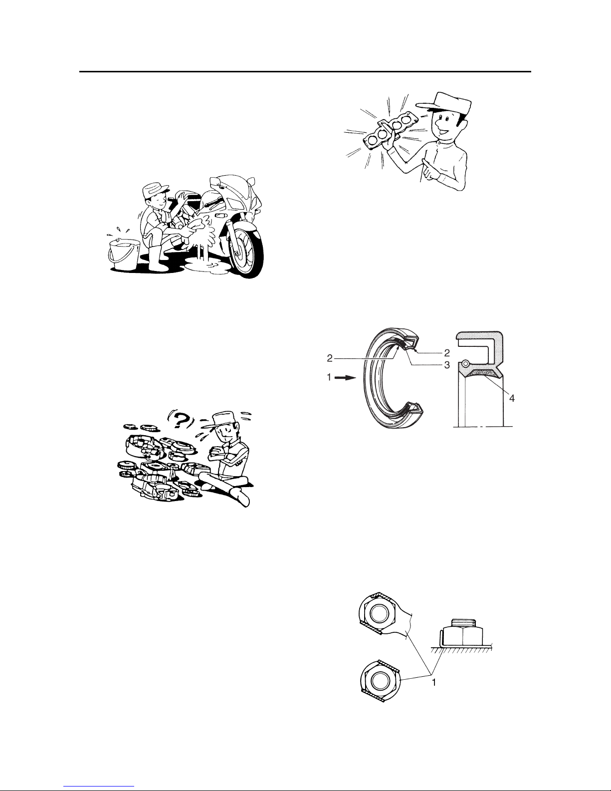
GASKETS, OIL SEALS AND O-RINGS
1. When overhauling the engine, replace all
gaskets, seals and O-rings. All gasket surfaces, oil seal lips and O-rings must be
cleaned.
2. During reassembly, properly oil all mating
parts and bearings and lubricate the oil
seal lips with grease.
EAS20220
LOCK WASHERS/PLATES AND COTTER
PINS
After removal, replace all lock washers/plates
“1” and cotter pins. After the bolt or nut has
been tightened to specification, bend the lock
tabs along a flat of the bolt or nut.
1. Oil
2. Lip
3. Spring
4. Grease
Manuals by Motomatrix / www.motomatrix.co.uk / The Solution For Lost Motorcycle Coded Keys
email: info@motomatrix.co.uk
IMPORTANT INFORMATION
1-21
EAS20230
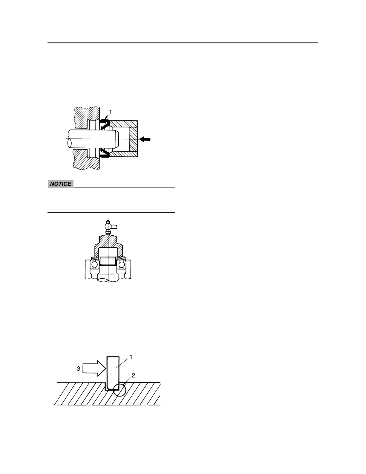
BEARINGS AND OIL SEALS
Install bearings and oil seals so that the manufacturer’s marks or numbers are visible. When
installing oil seals “1”, lubricate the oil seal lips
with a light coat of lithium-soap-based grease.
Oil bearings liberally when installing, if appropriate.
ECA13300
Do not spin the bearing with compressed
air because this will damage the bearing
surfaces.
EAS20240
CIRCLIPS
Before reassembly, check all circlips carefully
and replace damaged or distorted circlips.
Always replace piston pin clips after one use.
When installing a circlip “1”, make sure the
sharp-edged corner “2” is positioned opposite
the thrust “3” that the circlip receives.
Manuals by Motomatrix / www.motomatrix.co.uk / The Solution For Lost Motorcycle Coded Keys
email: info@motomatrix.co.uk
 Loading...