

Page 1

OWNER’S MANUAL
YZF-R1
5PW-28199-E0
Page 2

Page 3
EAU03338
INTRODUCTION
Welcome to the Yamaha world of motorcycling!
As the owner of a YZF-R1, you are benefiting from Yamaha’s vast experience and
newest technology regarding the design and manufacture of high-quality products,
which have earned Yamaha a reputation for dependability.
Please take the time to read this manual thoroughly, so as to enjoy all advantages of
your YZF-R1. The owner’s manual does not only instruct you in how to operate,
inspect and maintain your motorcycle, but also in how to safeguard yourself and others from trouble and injury.
In addition, the many tips given in this manual will help keep your motorcycle in the
best possible condition. If you have any further questions, do not hesitate to contact
your Yamaha dealer.
The Yamaha team wishes you many safe and pleasant rides. So, remember to put
safety first!
Page 4
IMPORTANT MANUAL INFORMATION
Particularly important information is distinguished in this manual by the following notations:
The Safety Alert Symbol means ATTENTION! BECOME ALERT! YOUR SAFETY IS
INVOLVED!
EAU00005
WARNING
CAUTION:
NOTE:
Failure to follow WARNING instructions could result in severe injury or death to the
motorcycle operator, a bystander, or a person inspecting or repairing the
motorcycle.
A CAUTION indicates special precautions that must be taken to avoid damage to the
motorcycle.
A NOTE provides key information to make procedures easier or clearer.
NOTE:
_
This manual should be considered a permanent part of this motorcycle and should remain
●
with it even if the motorcycle is subsequently sold.
Yamaha continually seeks advancements in product design and quality. Therefore, while
●
this manual contains the most current product information available at the time of printing,
there may be minor discrepancies between your motorcycle and this manual. If you have
any questions concerning this manual, please consult your Yamaha dealer.
_
Page 5
IMPORTANT MANUAL INFORMATION
EW000002
WARNING
_
PLEASE READ THIS MANUAL CAREFULLY AND COMPLETELY BEFORE OPERATING
THIS MOTORCYCLE.
_
Page 6
IMPORTANT MANUAL INFORMATION
YZF-R1
OWNER’S MANUAL
©2001 by Yamaha Motor Co., Ltd.
1st edition, November 2001
All rights reserved.
Any reprinting or unauthorized use
without the written permission of
Yamaha Motor Co., Ltd.
is expressly prohibited.
Printed in Japan.
EAU04229
Page 7
EAU00009
TABLE OF CONTENTS
1 GIVE SAFETY THE RIGHT OF WAY
2 DESCRIPTION
3 INSTRUMENT AND CONTROL FUNCTIONS
4 PRE-OPERATION CHECKS
5 OPERATION AND IMPORTANT RIDING POINTS
6 PERIODIC MAINTENANCE AND MINOR REPAIR
7 MOTORCYCLE CARE AND STORAGE
8 SPECIFICATIONS
9 CONSUMER INFORMATION
INDEX
1
2
3
4
5
6
7
8
9
Page 8

Page 9
GIVE SAFETY THE RIGHT OF WAY
GIVE SAFETY THE RIGHT OF WAY ................................................ 1-1
1
Page 10
1-
GIVE SAFETY THE RIGHT OF WAY
EAU00021
Motorcycles are fascinating vehicles, which can give you an unsurpassed feeling of power and
freedom. However, they also impose certain limits, which you must accept; even the best motorcycle
does not ignore the laws of physics.
1
Regular care and maintenance are essential for preserving value and operating condition of your
motorcycle. Moreover, what is true for the motorcycle is also true for the rider: good performance
depends on being in good shape. Riding under the influence of medication, drugs and alcohol is, of
course, out of the question. Motorcycle riders—more than car drivers—must always be at their mental
and physical best. Under the influence of even small amounts of alcohol, there is a tendency to take
dangerous risks.
Protective clothing is as essential for the motorcycle rider as seat belts are for car drivers and
passengers. Always wear a complete motorcycle suit (whether made of leather or tear-resistant
synthetic materials with protectors), sturdy boots, motorcycle gloves and a properly fitting helmet.
Optimum protective wear, however, should not encourage carelessness. Although full-coverage
helmets and suits, in particular, create an illusion of total safety and protection, motorcyclists will
always be vulnerable. Riders who lack critical self-control run the risk of going too fast and are apt to
take chances. This is even more dangerous in wet weather. The good motorcyclist rides safely,
predictably and defensively—avoiding all dangers, including those caused by others.
Enjoy your ride!
1-1
Page 11
DESCRIPTION
Left view ............................................................................................. 2-1
Right view........................................................................................... 2-2
Controls and instruments ................................................................... 2-3
2
Page 12
2-
DESCRIPTION
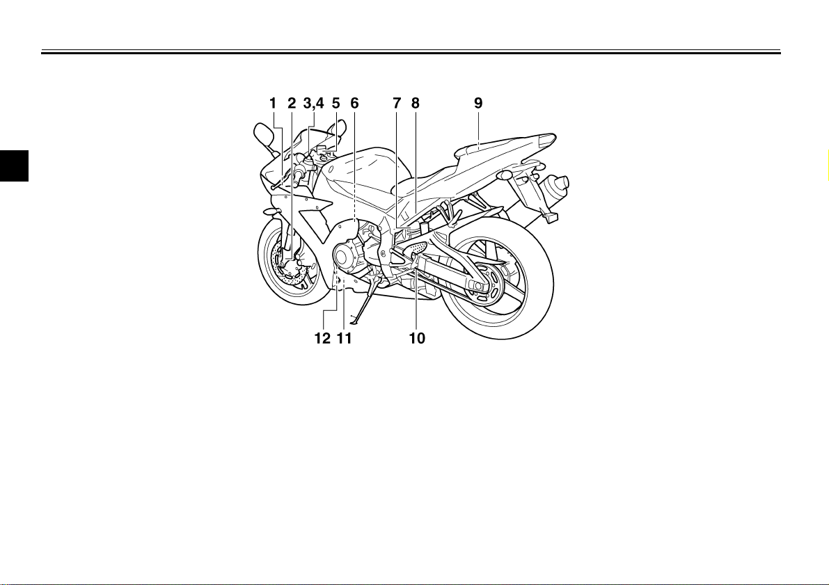
Left view
2
1. Fuse box (page 6-35)
2. Front fork compression damping force adjusting screw (page 3-20)
3. Front fork rebound damping force adjusting screw (page 3-20)
4. Front fork spring preload adjusting bolt (page 3-19)
5. Front brake fluid reservoir (page 6-26)
6. Throttle stop screw (page 6-18)
7. Shock absorber assembly spring preload adjusting ring (page 3-21)
8. Shock absorber assembly compression damping force adjusting screw (page 3-22)
9. Owner’s tool kit (page 6-1)
10. Shock absorber assembly rebound damping force adjusting screw (page 3-22)
11. Engine oil drain bolt (page 6-10)
12. Engine oil filter cartridge (page 6-10)
2-1
EAU00026
Page 13
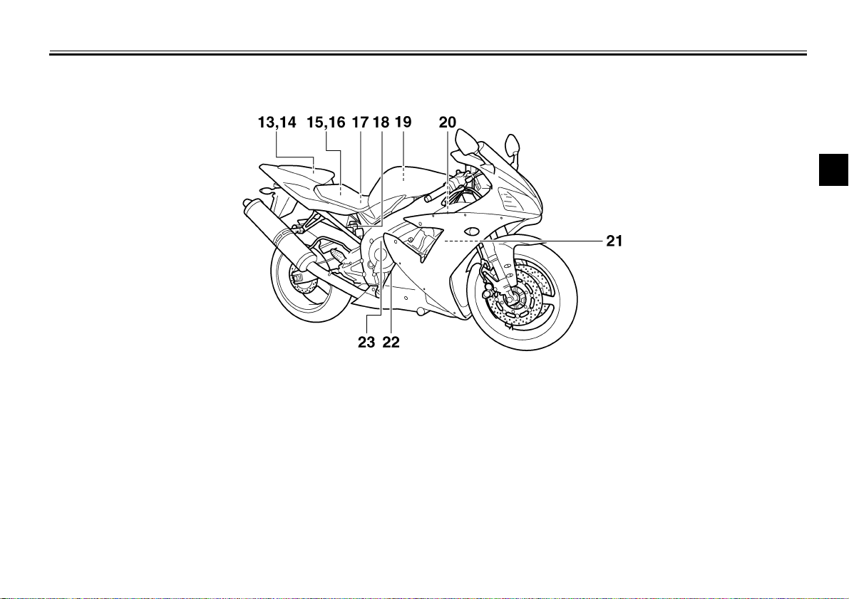
Right view
DESCRIPTION
2
13. Luggage strap holders (page 3-23)
14. Helmet holders (page 3-18)
15. Main fuse (page 6-35)
16. Electronic fuel injection fuse (page 6-35)
17. Battery (page 6-33)
18. Rear brake fluid reservoir (page 6-26)
19. Air filter element (page 6-16)
20. Radiator cap (page 6-13)
21. Coolant reservoir (page 6-12)
22. Engine oil level check window (page 6-9)
23. Engine oil filler cap (page 6-9)
2-2
Page 14
DESCRIPTION
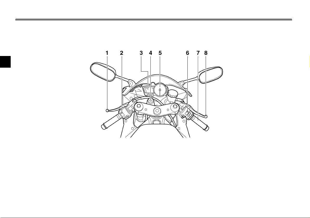
Controls and instruments
2
1. Clutch lever (page 3-13)
2. Left handlebar switches (page 3-11)
3. Multi-function display (page 3-6)
4. Main switch/steering lock (page 3-1)
5. Tachometer (page 3-11)
6. Right handlebar switches (page 3-12)
7. Throttle grip (page 6-19)
8. Brake lever (page 3-13)
2-3
Page 15
INSTRUMENT AND CONTROL FUNCTIONS
Main switch/steering lock .....................................3-1
Indicator and warning lights ................................3-2
Multi-function display ........................................... 3-6
Tachometer ........................................................3-11
Anti-theft alarm (optional) .................................. 3-11
Handlebar switches ........................................... 3-11
Clutch lever ........................................................ 3-13
Shift pedal .......................................................... 3-13
Brake lever .........................................................3-13
Brake pedal ........................................................ 3-14
Fuel tank cap ..................................................... 3-14
Fuel .................................................................... 3-15
Fuel tank breather hose .................................... 3-16
Catalytic converter ............................................ 3-16
Seats ................................................................. 3-17
Helmet holders .................................................. 3-18
Storage compartment ....................................... 3-19
Adjusting the front fork ...................................... 3-19
Adjusting the shock absorber assembly ............ 3-21
Luggage strap holders ...................................... 3-23
EXUP system .................................................... 3-24
Sidestand .......................................................... 3-24
Ignition circuit cut-off system ............................. 3-25
3
Page 16
3-
WARNING
INSTRUMENT AND CONTROL FUNCTIONS
3
EAU00029
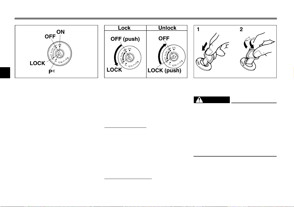
Main switch/steering lock
The main switch/steering lock controls
the ignition and lighting systems, and is
used to lock the steering. The various
LOCK
The steering is locked, and all electrical
systems are off. The key can be removed.
positions are described below.
To lock the steering
EAU00036
ON
All electrical systems are supplied with
power, and the engine can be started.
The key cannot be removed.
EAU00038
1. Turn the handlebars all the way to
the left.
2. Push the key in from the “OFF” position, and then turn it to “LOCK”
while still pushing it.
3. Remove the key.
OFF
All electrical systems are off. The key
can be removed.
To unlock the steering
Push the key in, and then turn it to
“OFF” while still pushing it.
EAU00040
EAU00027
1. Push.
2. Turn.
EW000016
_
Never turn the key to “OFF” or
“LOCK” while the motorcycle is
moving, otherwise the electrical
systems will be switched off, which
may result in loss of control or an
accident. Make sure that the motorcycle is stopped before turning the
key to “OFF” or “LOCK”.
_
3-1
Page 17
INSTRUMENT AND CONTROL FUNCTIONS
EAU04492
(Parking)
The steering is locked, and the taillight,
license plate light and auxiliary lights
are on, but all other electrical systems
are off. The key can be removed.
The steering must be locked before the
key can be turned to “”.
ECA00043
CAUTION:
_
Do not use the parking position for
an extended length of time, otherwise the battery may discharge.
_
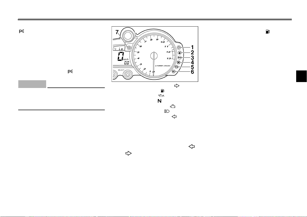
1. Right turn signal indicator light “”
2. Fuel level warning light “”
3. Oil level warning light “”
4. Neutral indicator light “”
5. Engine trouble warning light “”
6. High beam indicator light “”
7. Left turn signal indicator light “”
EAU03034
Indicator and warning lights
EAU04121
Turn signal indicator lights “”
and “”
The corresponding indicator light flashes when the turn signal switch is
pushed to the left or right.
EAU04303
Fuel level warning light “”
This warning light comes on when the
fuel level drops below approximately
3.3 L. When this occurs, refuel as soon
as possible.
The electrical circuit of the warning light
can be checked according to the following procedure.
1. Turn the key to “ON”.
2. If the warning light does not come
on for a few seconds, then go off,
have a Yamaha dealer check the
electrical circuit.
3
3-2
Page 18
INSTRUMENT AND CONTROL FUNCTIONS
3
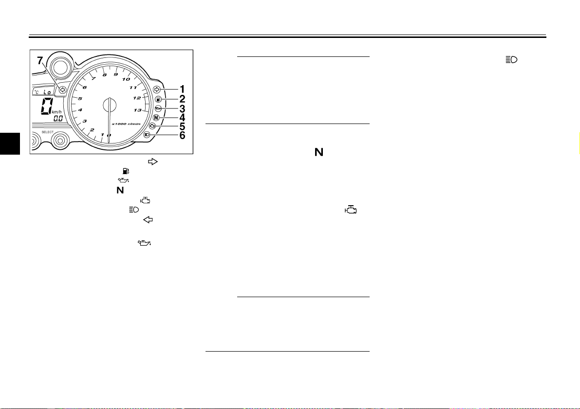
1. Right turn signal indicator light “”
2. Fuel level warning light “”
3. Oil level warning light “”
4. Neutral indicator light “”
5. Engine trouble warning light “”
6. High beam indicator light “”
7. Left turn signal indicator light “”
Oil level warning light “”
This warning light comes on when the
engine oil level is low.
The electrical circuit of the warning light
can be checked according to the following procedure.
1. Turn the key to “ON”.
2. If the warning light does not come
on for a few seconds, then go off,
have a Yamaha dealer check the
electrical circuit.
EAU04301
NOTE:
_
Even if the oil level is sufficient, the
warning light may flicker when riding on
a slope or during sudden acceleration
or deceleration, but this is not a malfunction.
_
EAU00061
Neutral indicator light “”
This indicator light comes on when the
transmission is in the neutral position.
EAU04514
Engine trouble warning light “”
This warning light comes on or flashes
when an electrical circuit monitoring
the engine is defective. When this occurs, have a Yamaha dealer check the
self-diagnosis system.
NOTE:
_
This warning light comes on for a few
seconds, then goes off when the key is
turned to “ON”, but this does not indicate a malfunction.
_
EAU00063
High beam indicator light “”
This indicator light comes on when the
high beam of the headlight is switched
on.
3-3
Page 19
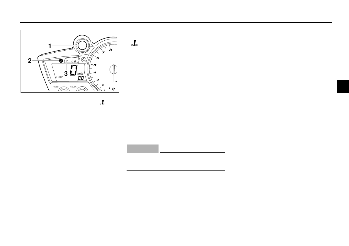
1. Engine speed indicator light
2. Coolant temperature warning light “”
3. Coolant temperature display
EAU04559
Engine speed indicator light
The electrical circuit of the indicator
light can be checked according to the
following procedure.
1. Turn the key to “ON”.
2. If the indicator light does not come
on for a few seconds, then go off,
have a Yamaha dealer check the
electrical circuit. (See pages 3-8–
3-10 for a detailed explanation of
the function of this indicator light
and on how to set it.)
INSTRUMENT AND CONTROL FUNCTIONS
EAU04515
Coolant temperature warning light
“”
This warning light comes on when the
engine overheats. When this occurs,
stop the engine immediately and allow
the engine to cool.
The electrical circuit of the warning light
can be checked according to the following procedure.
1. Turn the key to “ON”.
2. If the warning light does not come
on for a few seconds, then go off,
have a Yamaha dealer check the
electrical circuit.
CAUTION:
_
Do not operate the engine if it is
overheated.
_
EC000002
3
3-4
Page 20
INSTRUMENT AND CONTROL FUNCTIONS
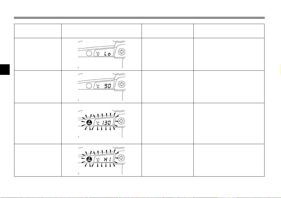
CB-25E
Coolant
temperature
0–39 °C
Display Conditions What to do
Message “LO” is
displayed.
OK. Go ahead with riding.
3
40–116 °C
117–139 °C
Above 140 °C
Temperature is
displayed.
Temperature flashes.
Warning light comes on.
Message “HI” flashes.
Warning light comes on.
OK. Go ahead with riding.
Stop the motorcycle and allow it to
idle until the coolant temperature
goes down.
If the temperature does not go
down, stop the engine. (See the
“Engine overheating” section on
page 6-46 for further instructions.)
Stop the engine and allow it to cool.
(See the “Engine overheating” section on page 6-46 for further instructions.)
3-5
Page 21
INSTRUMENT AND CONTROL FUNCTIONS
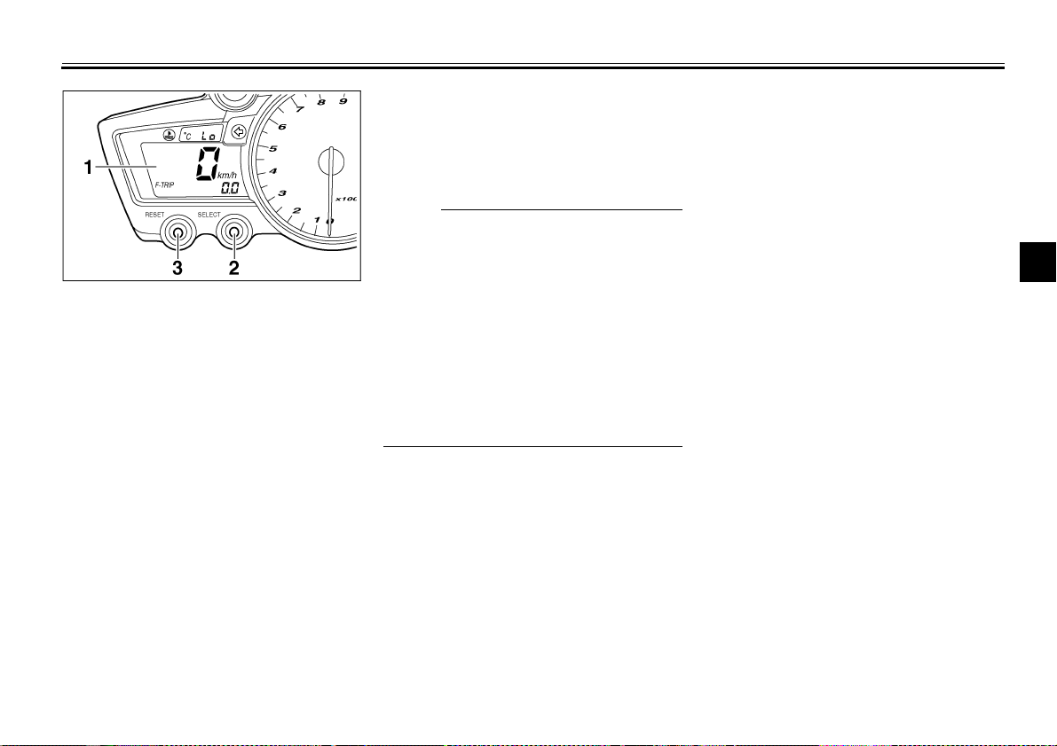
1. Multi-function display
2. “SELECT” button
3. “RESET” button
EAU04554
Multi-function display
The multi-function display is equipped
with the following:
a speedometer (which shows the
●
riding speed)
an odometer (which shows the to-
●
tal distance traveled)
two tripmeters (which show the
●
distance traveled since they were
last set to zero)
a fuel reserve tripmeter (which
●
shows the distance traveled since
the fuel level warning light came
on)
a clock
●
a self-diagnosis device
●
a display brightness and engine
●
speed indicator light control mode
NOTE:
_
Be sure to turn the key to “ON” be-
●
fore using the “SELECT” and
“RESET” buttons.
For the U.K. only: To switch the
●
speedometer and odometer/tripmeter displays between kilometers and miles, press the
“SELECT” button and “RESET”
button together for at least two
seconds.
_
Odometer and tripmeter modes
Pushing the “SELECT” button switches
the display between the odometer
mode “ODO” and the tripmeter modes
“TRIP 1” and “TRIP 2” in the following
order:
ODO → TRIP 1 → TRIP 2 → ODO
If the fuel level warning light comes on
(see page 3-2), the odometer display
will automatically change to the fuel reserve tripmeter mode “F-TRIP” and
start counting the distance traveled
from that point. In that case, pushing
the “SELECT” button switches the display between the various tripmeter and
odometer modes in the following order:
F-TRIP → TRIP 1 → TRIP 2 → ODO
F-TRIP
→
3
3-6
Page 22
INSTRUMENT AND CONTROL FUNCTIONS
CAUTION:
To reset a tripmeter, select it by pushing the “SELECT” button, and then
push the “RESET” button for at least
one second. If you do not reset the fuel
reserve tripmeter manually, it will reset
itself automatically and the display will
return to the prior mode after refueling
and traveling 5 km.
3
Clock mode
Turn the key to “ON”.
To change the display to the clock
mode, push the “SELECT” button for at
least one second.
To change the display back to the prior
mode, push the “SELECT” button.
To set the clock:
1. Push the “SELECT” button and
“RESET” button together for at
least two seconds.
2. When the hour digits start flashing,
push the “RESET” button to set
the hours.
3. Push the “SELECT” button, and
the minute digits will start flashing.
4. Push the “RESET” button to set
the minutes.
5. Push the “SELECT” button and
then release it to start the clock.
Self-diagnosis device
This model is equipped with a self-diagnosis device for various electrical circuits.
If any of those circuits are defective,
the engine trouble warning light will
come on, and then the multi-function
display will indicate a two-digit error
code (e.g., 11, 12, 13).
If the multi-function display indicates
such an error code, note the code number, and then have a Yamaha dealer
check the motorcycle.
ECA00127
_
If the display indicates an error
code, the motorcycle should be
checked as soon as possible in order to avoid engine damage.
_
3-7
Page 23
INSTRUMENT AND CONTROL FUNCTIONS
NOTE:
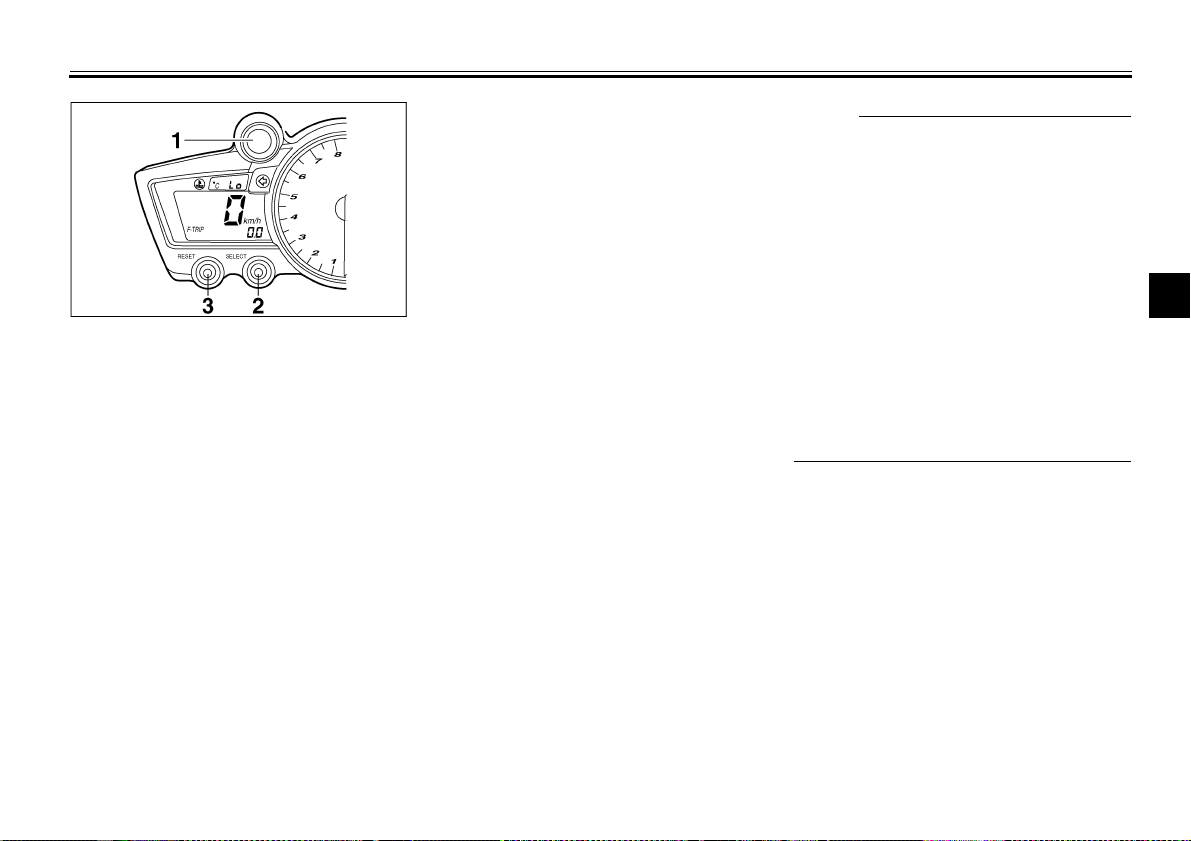
1. Engine speed indicator light
2. “SELECT” button
3. “RESET” button
Display brightness and engine
speed indicator light control mode
This mode cycles through five control
functions, allowing you to make the following settings in the order listed below.
1. Display brightness: This function
allows you to adjust the brightness
of the multi-function display to suit
the outside lighting conditions.
2. Engine speed indicator light activity: This function allows you to
choose whether or not the indicator light should be activated and
whether it should blink or stay on
when activated.
3. Engine speed indicator light activation: This function allows you to
select the engine speed at which
the indicator light will be activated.
4. Engine speed indicator light deactivation: This function allows you
to select the engine speed at
which the indicator light will be deactivated.
5. Engine speed indicator light
brightness: This function allows
you to adjust the brightness of the
indicator light to suit your preference.
_
To make any settings in this mode,
●
you have to cycle through all of its
functions. However, if the key is
turned to “OFF” or the engine is
started before completing the procedure, only the settings made before the “SELECT” button was last
pushed will be applied.
In this mode, the multi-function
●
display shows the current setting
for each function (except the engine speed indicator light activity
function).
_
3
3-8
Page 24
INSTRUMENT AND CONTROL FUNCTIONS
NOTE:
To adjust the display brightness
1. Turn the key to “OFF”.
2. Push and hold the “SELECT” button.
3. Turn the key to “ON”, and then, after five seconds, release the
“SELECT” button.
4. Push the “RESET” button to select
3
the desired display brightness level.
5. Push the “SELECT” button to confirm the selected display brightness level. The control mode
changes to the engine speed indicator light activity function.
To set the engine speed indicator light
activity function
1. Push the “RESET” button to select
one of the following indicator light
activity settings:
a. The indicator light will stay on
when activated. (This setting is selected when the indicator light
stays on.)
b. The indicator light will flash when
activated. (This setting is selected
when the indicator light flashes
four times per second.)
c. The indicator light is deactivated;
in other words, it will not come on
or flash. (This setting is selected
when the indicator light flashes
once every two seconds.)
2. Push the “SELECT” button to confirm the selected indicator light activity. The control mode changes
to the engine speed indicator light
activation function.
To set the engine speed indicator light
activation function
_
The indicator light activation function can
be set between 7,000 and 12,000 r/min
in increments of 500 r/min.
_
1. Push the “RESET” button to select
the desired engine speed for activating the indicator light.
2. Push the “SELECT” button to confirm the selected engine speed.
The control mode changes to the
engine speed indicator light deactivation function.
3-9
Page 25
INSTRUMENT AND CONTROL FUNCTIONS
To set the engine speed indicator light
deactivation function
NOTE:
_
The indicator light deactivation
●
function can be set between 7,000
and 12,000 r/min in increments of
500 r/min.
Be sure to set the deactivation
●
function to a higher engine speed
than for the activation function,
otherwise the engine speed indicator light will remain deactivated.
_
1. Push the “RESET” button to select
the desired engine speed for deactivating the indicator light.
2. Push the “SELECT” button to confirm the selected engine speed.
The control mode changes to the
engine speed indicator light brightness function.
To adjust the engine speed indicator
light brightness
1. Push the “RESET” button to select
the desired indicator light brightness level.
2. Push the “SELECT” button to confirm the selected indicator light
brightness level. The multi-function display will return to the odometer, tripmeter or clock mode.
3
3-10
Page 26
INSTRUMENT AND CONTROL FUNCTIONS
Anti-theft alarm (optional)
This motorcycle can be equipped with
an optional anti-theft alarm by a
Yamaha dealer. Contact a Yamaha
dealer for more information.
3
EAU00109
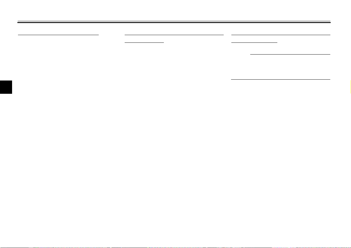
1. Tachometer
2. Tachometer red zone
EAU00101
Tachometer
The electric tachometer allows the rider
to monitor the engine speed and keep it
within the ideal power range.
CAUTION:
_
Do not operate the engine in the tachometer red zone.
Red zone: 11,750 r/min and above
_
EC000003
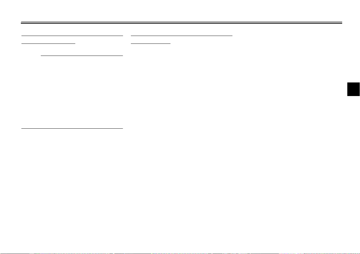
1. Pass switch “PASS”
2. Dimmer switch “ / ”
3. Turn signal switch “ / ”
4. Horn switch “”
EAU00118
Handlebar switches
EAU04553
Pass switch “PASS”
Press this switch to flash the headlights.
EAU03888
Dimmer switch “ / ”
Set this switch to “” for the high
beam and to “” for the low beam.
3-11
Page 27
INSTRUMENT AND CONTROL FUNCTIONS
CAUTION:
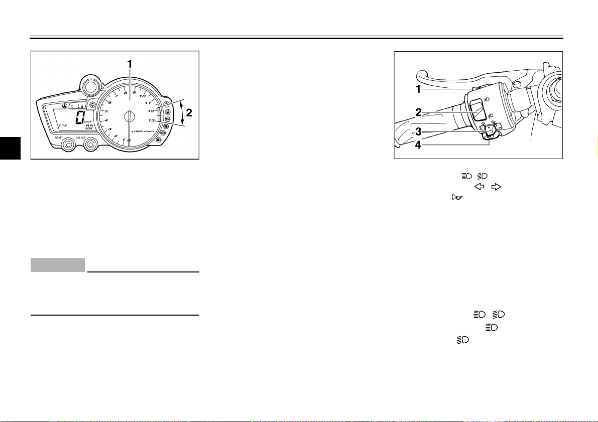
Turn signal switch “ / ”
To signal a right-hand turn, push this
switch to “”. To signal a left-hand
turn, push this switch to “”. When
released, the switch returns to the center position. To cancel the turn signal
lights, push the switch in after it has returned to the center position.
Horn switch “”
Press this switch to sound the horn.
EAU03889
EAU00129
1. Engine stop switch “ / ”
2. Light switch “ //”
3. Start switch “”
EAU03890
Engine stop switch “ / ”
Set this switch to “” before starting
the engine. Set this switch to “” to
stop the engine in case of an emergency, such as when the motorcycle overturns or when the throttle cable is
stuck.
EAU04557
Light switch “ //”
Set this switch to “” to turn on the
auxiliary lights, meter lighting, taillight
and license plate light. Set the switch to
“” to turn on the headlights also. Set
the switch to “” to turn off all the
lights.
3-12
EAU00143
Start switch “”
Push this switch to crank the engine
with the starter.
EC000005
_
See page 5-1 for starting instructions prior to starting the engine.
_
3
Page 28
INSTRUMENT AND CONTROL FUNCTIONS
3
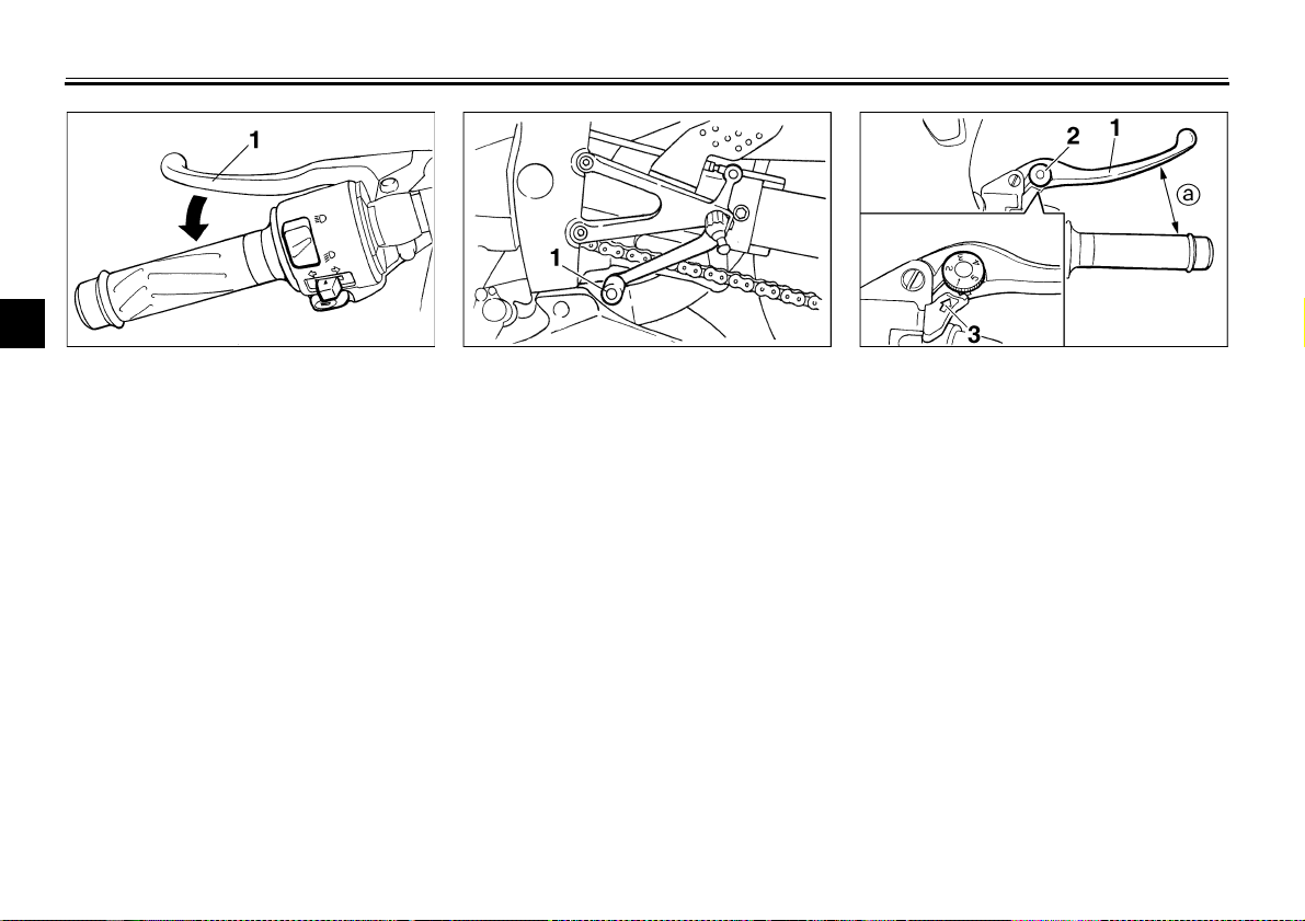
1. Clutch lever 1. Shift pedal 1. Brake lever
EAU00152
Clutch lever
The clutch lever is located at the left
handlebar grip. To disengage the
clutch, pull the lever toward the handlebar grip. To engage the clutch, release
the lever. The lever should be pulled
rapidly and released slowly for smooth
Shift pedal
The shift pedal is located on the left
side of the engine and is used in combination with the clutch lever when
shifting the gears of the 6-speed constant-mesh transmission equipped on
this motorcycle.
EAU00157
clutch operation.
The clutch lever is equipped with a
clutch switch, which is part of the ignition
circuit cut-off system. (See page 3-26
for an explanation of the ignition circuit
cut-off system.)
2. Brake lever position adjusting dial
3. Arrow mark
a. Distance between brake lever and handlebar
grip
Brake lever
The brake lever is located at the right
handlebar grip. To apply the front brake,
pull the lever toward the handlebar grip.
The brake lever is equipped with a position adjusting dial. To adjust the distance between the brake lever and the
handlebar grip, turn the adjusting dial
while holding the lever pushed away
from the handlebar grip. Make sure that
the appropriate setting on the adjusting
dial is aligned with the arrow mark on
the brake lever.
3-13
EAU00161
Page 29
INSTRUMENT AND CONTROL FUNCTIONS
NOTE:
WARNING
_
The fuel tank cap cannot be closed unless the key is in the lock. In addition,
the key cannot be removed if the cap is
not properly closed and locked.
_
EWA00025
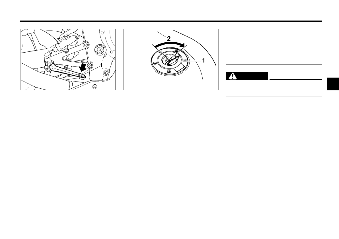
1. Brake pedal 1. Fuel tank cap lock cover
EAU00162
2. Unlock.
Brake pedal
The brake pedal is on the right side of
the motorcycle. To apply the rear
brake, press down on the brake pedal.
Fuel tank cap
To open the fuel tank cap
Open the fuel tank cap lock cover, insert the key into the lock, and then turn
it 1/4 turn clockwise. The lock will be released and the fuel tank cap can be
opened.
To close the fuel tank cap
1. Push the fuel tank cap into position with the key inserted in the
lock.
2. Remove the key, and then close
the lock cover.
3-14
EAU04068
_
Make sure that the fuel tank cap is
properly closed before riding.
_
3
Page 30
INSTRUMENT AND CONTROL FUNCTIONS
3
1. Fuel tank filler tube
2. Fuel level
Fuel
Make sure that there is sufficient fuel in
the tank. Fill the fuel tank to the bottom
of the filler tube as shown.
WARNING
_
Do not overfill the fuel tank, oth-
●
erwise it may overflow when the
fuel warms up and expands.
Avoid spilling fuel on the hot
●
engine.
_
EAU03753
EW000130
EAU00185
CAUTION:
_
Immediately wipe off spilled fuel
with a clean, dry, soft cloth, since
fuel may deteriorate painted surfaces or plastic parts.
_
EAU04518
Recommended fuel:
PREMIUM UNLEADED
GASOLINE ONLY
Fuel tank capacity:
Total amount:
17 L
Amount remaining when the fuel
level warning light comes on:
3.3 L
ECA00104
CAUTION:
_
Use only unleaded gasoline. The
use of leaded gasoline will cause severe damage to internal engine
parts, such as the valves and piston
rings, as well as to the exhaust system.
_
Your Yamaha engine has been designed to use regular unleaded gasoline with a research octane number of
95 or higher. If knocking (or pinging)
occurs, use a gasoline of a different
brand or premium unleaded fuel. Use
of unleaded fuel will extend spark plug
life and reduce maintenance costs.
3-15
Page 31

INSTRUMENT AND CONTROL FUNCTIONS
WARNING
CAUTION:
1. Fuel tank breather hose
Fuel tank breather hose
Before operating the motorcycle:
Check the fuel tank breather hose
●
connection.
Check the fuel tank breather hose
●
for cracks or damage, and replace
it if damaged.
Make sure that the end of the fuel
●
tank breather hose is not blocked,
and clean it if necessary.
EAU02955
EAU03098*
Catalytic converter
This motorcycle is equipped with a catalytic converter in the muffler.
_
The exhaust system is hot after operation. Make sure that the exhaust
system has cooled down before doing any maintenance work.
_
_
The following precautions must be
observed to prevent a fire hazard or
other damages.
Use only unleaded gasoline.
●
The use of leaded gasoline will
cause unrepairable damage to
the catalytic converter.
Never park the motorcycle near
●
possible fire hazards such as
grass or other materials that
easily burn.
Do not allow the engine to idle
●
too long.
_
EW000128
EC000114
3
3-16
Page 32

INSTRUMENT AND CONTROL FUNCTIONS
3
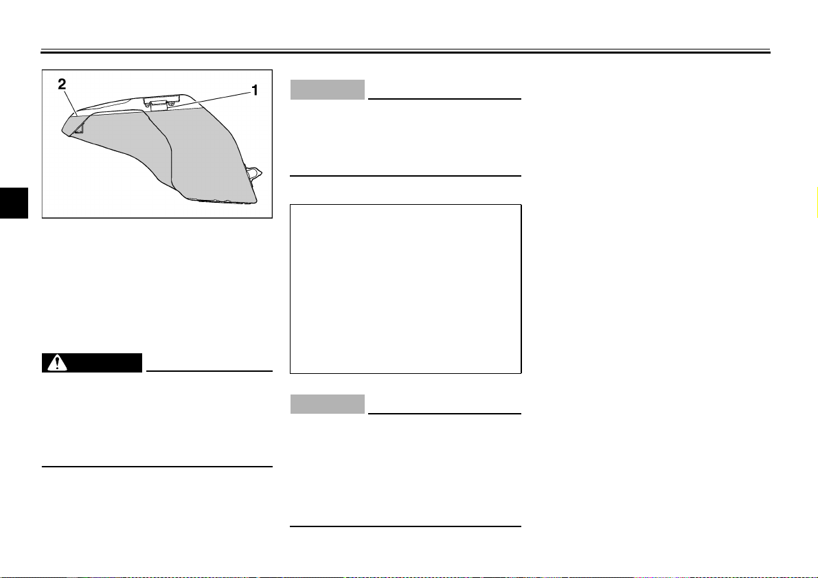
1. Bolt (× 2) 1. Projection
EAU04493
Seats
2. Seat holder
To install the rider seat
Insert the projection on the front of the
Rider seat
To remove the rider seat
Pull up the rear corners of the rider seat
rider seat into the seat holder as
shown, place the seat in the original
position, and then install the bolts.
as shown, remove the bolts, and then
pull the seat off.
1. Passenger seat lock
2. Unlock.
Passenger seat
To remove the passenger seat
1. Insert the key into the seat lock,
and then turn it counterclockwise.
2. While holding the key in that position, lift the front of the passenger
seat and pull it forward.
3-17
Page 33

WARNING
CAUTION:
1. Projection (× 2)
2. Seat holder
To install the passenger seat
1. Insert the projections on the rear
of the passenger seat into the seat
holder as shown, and then push
the front of the seat down to lock it
in place.
2. Remove the key.
NOTE:
_
Make sure that the seats are properly
secured before riding.
_
INSTRUMENT AND CONTROL FUNCTIONS
_
Never ride with a helmet attached to
a helmet holder, since the helmet
may hit objects, causing loss of
control and possibly an accident.
_
_
1. Helmet holder (× 2)
EAU04489
Helmet holders
The helmet holders are located on the
bottom of the passenger seat.
To secure a helmet to a helmet
holder
1. Remove the passenger seat. (See
page 3-17 for passenger seat removal and installation procedures.)
2. Attach the helmet to a helmet
holder, and then securely install
the passenger seat.
Some helmets may contact the muffler when secured to the right side
helmet holder because of their size
or shape. Be sure that your helmet
does not contact the muffler when it
is secured to the helmet holder.
_
To release a helmet from a helmet
holder
Remove the passenger seat, remove
the helmet from the helmet holder, and
then install the seat.
EWA00015
ECA00128
3
3-18
Page 34

INSTRUMENT AND CONTROL FUNCTIONS
EAU01862
Adjusting the front fork
This front fork is equipped with spring
preload adjusting bolts, rebound damping force adjusting screws and compression damping force adjusting
screws.
3
1. Storage compartment 1. Spring preload adjusting bolt
EAU01242
Storage compartment
The storage compartment is located
WARNING
_
Always adjust both fork legs equally, otherwise poor handling and loss
of stability may result.
_
under the passenger seat. (See
page 3-17 for passenger seat removal
and installation procedures.)
EWA00005
WARNING
_
Do not exceed the load limit of
●
3 kg for the storage compartment.
Do not exceed the maximum
●
load of 202 kg for the vehicle.
_
EW000035
Spring preload
To increase the spring preload and
thereby harden the suspension, turn
the adjusting bolt on each fork leg in direction a. To decrease the spring preload and thereby soften the
suspension, turn the adjusting bolt on
each fork leg in direction b.
3-19
Page 35

INSTRUMENT AND CONTROL FUNCTIONS
3
1. Current setting
2. Front fork cap bolt
NOTE:
_
Align the appropriate groove on the adjusting mechanism with the top of the
front fork cap bolt.
_
CI-10E
Minimum (soft) 8
Standard 6
Maximum (hard) 1
Setting
1. Rebound damping force adjusting screw
Rebound damping force
To increase the rebound damping
force and thereby harden the rebound
damping, turn the adjusting screw on
each fork leg in direction a. To decrease the rebound damping force and
thereby soften the rebound damping,
turn the adjusting screw on each fork
leg in direction b.
CI-02E
Minimum (soft) 26 clicks in direction b*
Standard 13 clicks in direction b*
Maximum (hard) 1 click in direction b*
* With the adjusting screw fully turned in direction
3-20
a
1. Compression damping force adjusting screw
Compression damping force
To increase the compression damping
force and thereby harden the compression damping, turn the adjusting screw
on each fork leg in direction a. To decrease the compression damping force
and thereby soften the compression
damping, turn the adjusting screw on
each fork leg in direction b.
CI-02E
Minimum (soft) 20 clicks in direction b*
Standard 13 clicks in direction b*
Maximum (hard) 1 click in direction b*
* With the adjusting screw fully turned in direction
a
Page 36

INSTRUMENT AND CONTROL FUNCTIONS
NOTE:
CAUTION:
_
Never attempt to turn an adjusting
mechanism beyond the maximum
or minimum settings.
_
NOTE:
_
Although the total number of clicks of a
3
damping force adjusting mechanism
may not exactly match the above specifications due to small differences in
production, the actual number of clicks
always represents the entire adjusting
range. To obtain a precise adjustment,
it would be advisable to check the number of clicks of each damping force adjusting mechanism and to modify the
specifications as necessary.
_
EC000015
EAU04496
Adjusting the shock absorber
assembly
This shock absorber assembly is
equipped with a spring preload adjusting ring and rebound and compression
damping force adjusting screws.
CAUTION:
_
Never attempt to turn an adjusting
mechanism beyond the maximum
or minimum settings.
_
EC000015
1. Spring preload adjusting ring
2. Special wrench
3. Position indicator
Spring preload
To increase the spring preload and
thereby harden the suspension, turn
the adjusting ring in direction a. To decrease the spring preload and thereby
soften the suspension, turn the adjusting ring in direction b.
_
Align the appropriate notch in the
●
adjusting ring with the position indicator on the shock absorber.
Use the special wrench included in
●
the owner’s tool kit to make the adjustment.
_
3-21
Page 37

INSTRUMENT AND CONTROL FUNCTIONS
CI-10E
Minimum (soft) 1
Standard 4
Maximum (hard) 9
Setting
1. Rebound damping force adjusting screw
Rebound damping force
To increase the rebound damping
force and thereby harden the rebound
damping, turn the adjusting screw in direction a. To decrease the rebound
damping force and thereby soften the
rebound damping, turn the adjusting
screw in direction b.
CI-14E
Minimum (soft) 20 clicks in direction b*
Standard 15 clicks in direction b*
Maximum (hard) 1 click in direction b*
* With the adjusting screw fully turned in direction
a
1. Compression damping force adjusting screw
Compression damping force
To increase the compression damping
force and thereby harden the compression damping, turn the adjusting screw
in direction a. To decrease the compression damping force and thereby
soften the compression damping, turn
the adjusting screw in direction b.
CI-14E
Minimum (soft) 20 clicks in direction b*
Standard 15 clicks in direction b*
Maximum (hard) 1 click in direction b*
* With the adjusting screw fully turned in direction
a
3
3-22
Page 38

INSTRUMENT AND CONTROL FUNCTIONS
NOTE:
_
Although the total number of clicks of a
damping force adjusting mechanism
may not exactly match the above specifications due to small differences in
production, the actual number of clicks
always represents the entire adjusting
range. To obtain a precise adjustment,
3
it would be advisable to check the number of clicks of each damping force adjusting mechanism and to modify the
specifications as necessary.
_
EAU00315
WARNING
_
This shock absorber contains highly pressurized nitrogen gas. For
proper handling, read and understand the following information before handling the shock absorber.
The manufacturer cannot be held responsible for property damage or
personal injury that may result from
improper handling.
Do not tamper with or attempt to
●
open the gas cylinder.
Do not subject the shock ab-
●
sorber to an open flame or other
high heat sources, otherwise it
may explode due to excessive
gas pressure.
Do not deform or damage the
●
gas cylinder in any way, as this
will result in poor damping performance.
Always have a Yamaha dealer
●
service the shock absorber.
_
1. Luggage strap holder (× 4)
2. Hook (× 4)
EAU03170
Luggage strap holders
There are four luggage strap holders
on the bottom of the passenger seat.
To use the strap holders, remove the
passenger seat, unhook the straps,
and then install the seat with the straps
hanging out from under the passenger
seat. (See page 3-17 for passenger
seat removal and installation procedures.)
3-23
Page 39

INSTRUMENT AND CONTROL FUNCTIONS
WARNING
EAU01571
EXUP system
This motorcycle is equipped with
Yamaha’s EXUP (EXhaust Ultimate
Power valve) system. This system
boosts engine power by means of a
valve that regulates the diameter of the
exhaust pipe. The EXUP system valve
is constantly adjusted in accordance
with the engine speed by a computercontrolled servomotor.
CAUTION:
_
The EXUP system has been set
●
and extensively tested at the
Yamaha factory. Changing
these settings without sufficient
technical knowledge may result
in poor performance of or damage to the engine.
If the EXUP system does not op-
●
erate, have a Yamaha dealer
check it.
_
EC000027
EAU00330
Sidestand
The sidestand is located on the left side
of the frame. Raise the sidestand or
lower it with your foot while holding the
motorcycle upright.
NOTE:
_
The built-in sidestand switch is part of
the ignition circuit cut-off system, which
cuts the ignition in certain situations.
(See further down for an explanation of
the ignition circuit cut-off system.)
_
EW000044
_
The motorcycle must not be ridden
with the sidestand down, or if the
sidestand cannot be properly
moved up (or does not stay up), otherwise the sidestand could contact
the ground and distract the operator, resulting in a possible loss of
control. Yamaha’s ignition circuit
cut-off system has been designed to
assist the operator in fulfilling the
responsibility of raising the sidestand before starting off. Therefore,
check this system regularly as described below and have a Yamaha
dealer repair it if it does not function
properly.
_
3
3-24
Page 40

INSTRUMENT AND CONTROL FUNCTIONS
EAU03720
Ignition circuit cut-off system
The ignition circuit cut-off system (comprising the sidestand switch, clutch
switch and neutral switch) has the following functions.
It prevents starting when the trans-
●
3
mission is in gear and the sidestand is up, but the clutch lever is
not pulled.
It prevents starting when the trans-
●
mission is in gear and the clutch
lever is pulled, but the sidestand is
still down.
It cuts the running engine when
●
the transmission is in gear and the
sidestand is moved down.
Periodically check the operation of the
ignition circuit cut-off system according
to the following procedure.
EW000045
WARNING
_
If a malfunction is noted, have a
Yamaha dealer check the system
before riding.
_
3-25
Page 41

CD-01E
INSTRUMENT AND CONTROL FUNCTIONS
With the engine turned off:
1. Move the sidestand down.
2. Make sure that the engine stop switch is set to “”.
3. Turn the key to “ON”.
4. Shift the transmission into the neutral position.
5. Push the start switch.
Does the engine start?
YES
With the engine still running:
6. Move the sidestand up.
7. Keep the clutch lever pulled.
8. Shift the transmission into gear.
9. Move the sidestand down.
Does the engine stall?
YES NO
After the engine has stalled:
10. Move the sidestand up.
11. Keep the clutch lever pulled.
12. Push the start switch.
Does the engine start?
YES NO
The system is OK.
The motorcycle can be ridden.
NO
NOTE:
This check is most reliable if performed with
a warmed-up engine.
The neutral switch may be defective.
The motorcycle should not be ridden
checked by a Yamaha dealer.
The sidestand switch may be defective.
The motorcycle should not be ridden
checked by a Yamaha dealer.
The clutch switch may be defective.
The motorcycle should not be ridden
checked by a Yamaha dealer.
until
until
until
3
3-26
Page 42

Page 43

PRE-OPERATION CHECKS
Pre-operation check list ..................................................................... 4-1
4
Page 44

4-
PRE-OPERATION CHECKS
The condition of a vehicle is the owner’s responsibility. Vital components can start to deteriorate quickly and unexpectedly,
even if the vehicle remains unused (for example, as a result of exposure to the elements). Any damage, fluid leakage or loss
of tire air pressure could have serious consequences. Therefore, it is very important, in addition to a thorough visual inspection, to check the following points before each ride.
Pre-operation check list
4
CO-01E
Fuel
Engine oil
Coolant
Front brake
Rear brake
Clutch
Throttle grip
ITEM CHECKS PAGE
• Check fuel level in fuel tank.
• Refuel if necessary.
• Check fuel line for leakage.
• Check oil level in engine.
• If necessary, add recommended oil to specified level.
• Check vehicle for oil leakage.
• Check coolant level in reservoir.
• If necessary, add recommended coolant to specified level.
• Check cooling system for leakage.
• Check operation.
• If soft or spongy, have Yamaha dealer bleed hydraulic system.
• Check fluid level in reservoir.
• If necessary, add recommended brake fluid to specified level.
• Check hydraulic system for leakage.
• Check operation.
• If soft or spongy, have Yamaha dealer bleed hydraulic system.
• Check fluid level in reservoir.
• If necessary, add recommended brake fluid to specified level.
• Check hydraulic system for leakage.
• Check operation.
• Lubricate cable if necessary.
• Check lever free play.
• Adjust if necessary.
• Make sure that operation is smooth.
• Check cable free play.
• If necessary, have Yamaha dealer adjust cable free play and lubricate cable and
grip housing.
3-15
6-9
6-12–6-13
6-25–6-27
6-24–6-27
6-23
6-19, 6-30
EAU01114
EAU03439
4-1
Page 45

PRE-OPERATION CHECKS
ITEM CHECKS PAGE
Control cables
Drive chain
Wheels and tires
Brake and shift pedals
Brake and clutch levers
Sidestand
Chassis fasteners
Instruments, lights, signals
and switches
Sidestand switch
NOTE:
_
• Make sure that operation is smooth.
• Lubricate if necessary.
• Check chain slack.
• Adjust if necessary.
• Check chain condition.
• Lubricate if necessary.
• Check for damage.
• Check tire condition and tread depth.
• Check air pressure.
• Correct if necessary.
• Make sure that operation is smooth.
• Lubricate the brake pedal pivoting point if necessary.
• Make sure that operation is smooth.
• Lubricate lever pivoting points if necessary.
• Make sure that operation is smooth.
• Lubricate pivot if necessary.
• Make sure that all nuts, bolts and screws are properly tightened.
• Tighten if necessary.
• Check operation.
• Correct if necessary.
• Check operation of ignition circuit cut-off system.
• If system is defective, have Yamaha dealer check vehicle.
Pre-operation checks should be made each time the motorcycle is used. Such an inspection can be accomplished in a very
short time; and the added safety it assures is more than worth the time involved.
_
WARNING
_
If any item in the Pre-operation check list is not working properly, have it inspected and repaired before operating
the motorcycle.
_
6-29
6-27–6-28
6-19–6-22
6-31
6-30
6-31
—
—
3-26
EWA00033
4
4-2
Page 46

Page 47

OPERATION AND IMPORTANT RIDING POINTS
Starting a cold engine ....................................................................... 5-1
Shifting .............................................................................................. 5-2
Recommended shift points (for Switzerland only) ............................. 5-3
Tips for reducing fuel consumption ................................................... 5-3
Engine break-in ................................................................................. 5-3
Parking .............................................................................................. 5-4
5
Page 48

5-
CAUTION:
NOTE:
OPERATION AND IMPORTANT RIDING POINTS
EAU00372
EAU00373
WARNING
_
●
Become thoroughly familiar
with all operating controls and
their functions before riding.
Consult a Yamaha dealer re-
garding any control or function
that you do not thoroughly un-
derstand.
●
Never start the engine or oper-
Starting a cold engine
In order for the ignition circuit cut-off
system to enable starting, one of the
following conditions must be met:
The transmission is in the neutral
●
position.
The transmission is in gear with
●
the clutch lever pulled and the
sidestand up.
ate it in a closed area for any
WARNING
5
length of time. Exhaust fumes
are poisonous, and inhaling
them can cause loss of con-
sciousness and death within a
short time. Always make sure
that there is adequate ventila-
tion.
●
Before starting out, make sure
that the sidestand is up. If the
sidestand is not raised com-
pletely, it could contact the
_
●
Before starting the engine,
check the function of the ignition circuit cut-off system according to the procedure
described on page 3-26.
●
Never ride with the sidestand
down.
_
1. Turn the key to “ON” and make
sure that the engine stop switch is
set to “”.
ground and distract the operator, resulting in a possible loss
of control.
_
EAU04560
EW000054
ECA00132
_
The following warning lights and indicator light should come on for a
few seconds, then go off.
●
Oil level warning light
●
Fuel level warning light
●
Coolant temperature warning
light
●
Engine speed indicator light
●
Engine trouble warning light
If a warning or indicator light does
not go off, see pages 3-2–3-5 for the
corresponding warning and indicator light circuit check.
_
2. Shift the transmission into the neutral position.
_
When the transmission is in the neutral
position, the neutral indicator light
should be on, otherwise have a
Yamaha dealer check the electrical circuit.
_
3. Start the engine by pushing the
start switch.
5-1
Page 49

OPERATION AND IMPORTANT RIDING POINTS
CAUTION:
NOTE:
_
If the engine fails to start, release the
start switch, wait a few seconds, and
then try again. Each starting attempt
should be as short as possible to preserve the battery. Do not crank the engine more than 10 seconds on any one
attempt.
_
CAUTION:
_
ECA00045
For maximum engine life, never accelerate hard when the engine is
cold!
_
NOTE:
_
The engine is warm when it quickly responds to the throttle.
_
1. Shift pedal
N. Neutral position
EAU00423
Shifting
Shifting gears lets you control the
amount of engine power available for
starting off, accelerating, climbing hills,
etc.
The gear positions are shown in the illustration.
NOTE:
_
To shift the transmission into the neutral position, press the shift pedal down
repeatedly until it reaches the end of its
travel, and then slightly raise it.
_
_
Even with the transmission in
●
the neutral position, do not
coast for long periods of time
with the engine off, and do not
tow the motorcycle for long distances. The transmission is
properly lubricated only when
the engine is running. Inadequate lubrication may damage
the transmission.
Always use the clutch while
●
changing gears to avoid damaging the engine, transmission,
and drive train, which are not
designed to withstand the
shock of forced shifting.
_
EC000048
5
5-2
Page 50

OPERATION AND IMPORTANT RIDING POINTS
Recommended shift points
(for Switzerland only)
The recommended shift points during
acceleration are shown in the table below.
CF-02E
1st → 2nd
2nd → 3rd
3rd → 4th
4th → 5th
5
5th → 6th
NOTE:
_
When shifting down two gears at a
time, reduce the speed accordingly
(e.g., down to 35 km/h when shifting
from 5th to 3rd gear).
_
Shift point
(km/h)
20
30
40
50
60
EAU02937
EAU03952
Tips for reducing fuel
consumption
Fuel consumption depends largely on
your riding style. Consider the following
tips to reduce fuel consumption:
Thoroughly warm up the engine.
●
Shift up swiftly, and avoid high en-
●
gine speeds during acceleration.
Do not rev the engine while shift-
●
ing down, and avoid high engine
speeds with no load on the engine.
Turn the engine off instead of let-
●
ting it idle for an extended length
of time (e.g., in traffic jams, at traffic lights or at railroad crossings).
EAU01128
Engine break-in
There is never a more important period
in the life of your engine than the period
between 0 and 1,600 km. For this reason, you should read the following material carefully.
Since the engine is brand new, do not
put an excessive load on it for the first
1,600 km. The various parts in the engine wear and polish themselves to the
correct operating clearances. During
this period, prolonged full-throttle operation or any condition that might result
in engine overheating must be avoided.
5-3
Page 51

OPERATION AND IMPORTANT RIDING POINTS
WARNING
CAUTION:
EAU03172*
0–1,000 km
Avoid prolonged operation above
6,000 r/min.
1,000–1,600 km
Avoid prolonged operation above
7,000 r/min.
EC000052*
CAUTION:
_
After 1,000 km of operation, the engine oil must be changed and the oil
filter cartridge replaced.
_
1,600 km and beyond
The vehicle can now be operated normally.
EC000053
CAUTION:
_
Keep the engine speed out of
●
the tachometer red zone.
If any engine trouble should oc-
●
cur during the engine break-in
period, immediately have a
Yamaha dealer check the vehicle.
_
NOTE:
_
During and after the engine break-in
period, the exhaust heat may cause
discoloration of the exhaust pipe, but
this is normal.
_
EAU00461
Parking
When parking, stop the engine, and
then remove the key from the main
switch.
_
Since the engine and exhaust
●
system can become very hot,
park in a place where pedestrians or children are not likely to
touch them.
Do not park on a slope or on
●
soft ground, otherwise the
motorcycle may overturn.
_
_
Never park in an area where there
are fire hazards such as grass or
other flammable materials.
_
EW000058
EC000062
5
5-4
Page 52

Page 53

PERIODIC MAINTENANCE AND MINOR REPAIR
Owner’s tool kit ....................................................6-1
Periodic maintenance and lubrication chart .........6-2
Removing and installing cowlings and panels .....6-5
Checking the spark plugs .................................... 6-8
Engine oil and oil filter cartridge ..........................6-9
Coolant .............................................................. 6-12
Replacing the air filter element ..........................6-16
Adjusting the engine idling speed ...................... 6-18
Adjusting the throttle cable free play ..................6-19
Adjusting the valve clearance ............................ 6-19
Tires ................................................................... 6-19
Cast wheels ....................................................... 6-22
Adjusting the clutch lever free play .................... 6-23
Adjusting the brake pedal position .....................6-24
Adjusting the rear brake light switch ..................6-24
Checking the front and rear brake pads .............6-25
Checking the brake fluid level ............................6-26
Changing the brake fluid .................................... 6-27
Drive chain slack ................................................ 6-27
Lubricating the drive chain .................................6-29
Checking and lubricating the cables .................. 6-29
Checking and lubricating the throttle grip and
cable ............................................................... 6-30
Checking and lubricating the brake and clutch
levers ............................................................... 6-30
Lubricating the brake pedal ............................... 6-31
Checking and lubricating the sidestand ............ 6-31
Checking the front fork ...................................... 6-31
Checking the steering ....................................... 6-32
Checking the wheel bearings ............................ 6-33
Battery ............................................................... 6-33
Replacing the fuses .......................................... 6-35
Replacing a headlight bulb ................................ 6-36
Tail/brake light ................................................... 6-37
Replacing a turn signal light bulb ...................... 6-37
Replacing the license plate light bulb ................ 6-38
Supporting the motorcycle ................................ 6-39
Front wheel ....................................................... 6-39
Rear wheel ........................................................ 6-42
Troubleshooting ................................................. 6-44
Troubleshooting charts ...................................... 6-45
6
Page 54

6-
NOTE:
WARNING
PERIODIC MAINTENANCE AND MINOR REPAIR
EAU00462
Safety is an obligation of the owner.
Periodic inspection, adjustment and lubrication will keep your vehicle in the
safest and most efficient condition possible. The most important points of inspection, adjustment, and lubrication
are explained on the following pages.
The intervals given in the periodic
maintenance and lubrication chart
should be simply considered as a general guide under normal riding conditions. However, DEPENDING ON THE
WEATHER, TERRAIN, GEOGRAPHICAL LOCATION, AND INDIVIDUAL
6
USE, THE MAINTENANCE INTERVALS MAY NEED TO BE SHORTENED.
WARNING
_
If you are not familiar with motorcycle maintenance work, have a
Yamaha dealer do it for you.
_
EAU00464
EW000060
1. Owner’s tool kit
EAU04223
Owner’s tool kit
The owner’s tool kit is located inside
the storage compartment under the
passenger seat. (See page 3-17 for
passenger seat removal and installation procedures.)
The service information included in this
manual and the tools provided in the
owner’s tool kit are intended to assist
you in the performance of preventive
maintenance and minor repairs. However, additional tools such as a torque
wrench may be necessary to perform
certain maintenance work correctly.
_
If you do not have the tools or experience required for a particular job, have
a Yamaha dealer perform it for you.
_
_
EW000063
Modifications not approved by
Yamaha may cause loss of performance and render the vehicle unsafe for use. Consult a Yamaha
dealer before attempting any changes.
_
6-1
Page 55

PERIODIC MAINTENANCE AND MINOR REPAIR
Periodic maintenance and lubrication chart
NOTE:
_
The annual checks must be performed every year, except if a kilometer-based maintenance is performed instead.
●
From 50,000 km, repeat the maintenance intervals starting from 10,000 km.
●
Items marked with an asterisk should be performed by a Yamaha dealer as they require special tools, data and techni-
●
cal skills.
_
CP-03E
NO. ITEM CHECK OR MAINTENANCE JOB
1
Fuel line • Check fuel hoses for cracks or damage. √√√√ √
*
• Check condition.
2
Spark plugs
*
3
Valves
*
4 Air filter element • Replace. √
5Clutch
6
Front brake
*
7
Rear brake
*
8
Brake hoses
*
9
Wheels • Check runout and for damage. √√√√
*
• Clean and regap.
• Replace. √√
• Check valve clearance.
• Adjust.
• Check operation.
• Adjust.
• Check operation, fluid level and vehicle for fluid leakage.
(See NOTE on page 6-4.)
• Replace brake pads. Whenever worn to the limit
• Check operation, fluid level and vehicle for fluid leakage.
(See NOTE on page 6-4.)
• Replace brake pads. Whenever worn to the limit
• Check for cracks or damage. √√√√ √
• Replace. (See NOTE on page 6-4.) Every 4 years
6-2
ODOMETER READING (× 1,000 km)
1 10203040
√√
Every 40,000 km
√√√√√
√√ √ √ √ √
√√ √ √ √ √
EAU03685
ANNUAL
CHECK
6
Page 56

PERIODIC MAINTENANCE AND MINOR REPAIR
NO. ITEM CHECK OR MAINTENANCE JOB
• Check tread depth and for damage.
10*Tires
11
Wheel bearings • Check bearing for looseness or damage. √√√√
*
12
Swingarm
*
13 Drive chain
14
Steering bearings
*
15
Chassis fasteners • Make sure that all nuts, bolts and screws are properly tightened. √√√√ √
6
*
16 Sidestand
Sidestand switch • Check operation. √√√√√ √
17
*
Front fork • Check operation and for oil leakage. √√√√
18
*
Shock absorber
19
*
assembly
Rear suspension relay
arm and connecting arm
20
*
pivoting points
21
Electronic fuel injection • Adjust engine idling speed and synchronization. √√√√√ √
*
22 Engine oil
23 Engine oil filter cartridge • Replace. √√√
• Replace if necessary.
• Check air pressure.
• Correct if necessary.
• Check operation and for excessive play. √√√√
• Lubricate with lithium-soap-based grease. Every 50,000 km
• Check chain slack.
• Make sure that the rear wheel is properly aligned.
• Clean and lubricate.
• Check bearing play and steering for roughness. √√√√√
• Lubricate with lithium-soap-based grease. Every 20,000 km
• Check operation.
• Lubricate.
• Check operation and shock absorber for oil leakage. √√√√
• Check operation. √√√√
• Change.
• Check oil level and vehicle for oil leakage.
ODOMETER READING (× 1,000 km)
1 10203040
√√√√ √
Every 1,000 km and after washing
the motorcycle or riding in the rain
√√√√ √
√√√√√ √
ANNUAL
CHECK
6-3
Page 57

PERIODIC MAINTENANCE AND MINOR REPAIR
NO. ITEM CHECK OR MAINTENANCE JOB
24*Cooling system
Front and rear brake
25
*
switches
26 Moving parts and cables • Lubricate. √√√√ √
Throttle grip housing
27
*
and cable
28
Air induction system
*
Muffler and exhaust pipe • Check the screw clamp for looseness. √√√√√
29
*
Lights, signals and
30
*
switches
NOTE:
_
Air filter
●
• Check coolant level and vehicle for coolant leakage. √√√√ √
• Change. Every 3 years
• Check operation. √√√√√ √
• Check operation and free play.
• Adjust the throttle cable free play if necessary.
• Lubricate the throttle grip housing and cable.
• Check the air cut-off valve, reed valve, and hose for
damage.
• Replace any damaged parts if necessary.
• Check operation.
• Adjust headlight beam.
ODOMETER READING (× 1,000 km)
1 10203040
√√√√ √
√√√√ √
√√√√√ √
ANNUAL
CHECK
EAU04522
• This model’s air filter is equipped with a disposable oil-coated paper element, which must not be cleaned with compressed air to avoid damaging it.
• The air filter element needs to be replaced more frequently when riding in unusually wet or dusty areas.
Hydraulic brake service
●
• Regularly check and, if necessary, correct the brake fluid level.
• Every two years replace the internal components of the brake master cylinders and calipers, and change the brake
fluid.
• Replace the brake hoses every four years and if cracked or damaged.
_
6
6-4
Page 58

PERIODIC MAINTENANCE AND MINOR REPAIR
1. Panel A
2. Cowling A
3. Cowling B
Removing and installing
cowlings and panels
6
The cowlings and panels shown above
need to be removed to perform some
of the maintenance jobs described in
this chapter. Refer to this section each
time a cowling or panel needs to be removed and installed.
EAU01139
1. Panel B
2. Cowling B
1. Quick fastener (× 4)
EAU04544
Cowling A
To remove the cowling
1. Remove the quick fasteners at the
front of the cowling.
6-5
Page 59

PERIODIC MAINTENANCE AND MINOR REPAIR
NOTE:
After removal
Before installation
1. Quick fastener screw (× 6)
2. Screw
3. Bolt (× 2)
2. Remove the bolts and screw, and
3. Slide the cowling backward at the
then loosen the quick fastener
screws 1/4 turn counterclockwise.
area shown.
1. Turn signal light lead coupler
2. Screw (× 2)
4. Disconnect the turn signal light
lead coupler.
5. Remove the screws, and then take
the cowling off.
To install the cowling
1. Install the screws.
2. Connect the turn signal light lead
coupler.
3. Place the cowling in the original
position.
4. Install the screw and the bolts,
tighten the quick fastener screws,
and then install the quick fasteners.
6-6
1. Quick fastener
_
To install the quick fastener, push the
center pin out so that it will protrude
from the fastener head, insert the fastener into the cowling, and then push
the protruding pin in until it is flush with
the fastener head.
_
6
Page 60

PERIODIC MAINTENANCE AND MINOR REPAIR
Right side
1. Quick fastener screw (× 4)
2. Cowling B
3. Bolt
Cowling B
To remove the cowling
6
Remove the bolts, loosen the quick fastener screws 1/4 turn counterclockwise, and then take the cowling off.
EAU04555
Left side
1. Bolt
2. Quick fastener screw (× 3)
3. Cowling B
To install the cowling
Place the cowling in the original position, and then tighten the quick fastener
screws and install the bolts.
1. Quick fastener screw (× 2)
2. Screw
EAU04531
Panels A and B
To remove one of the panels
Loosen the quick fastener screws 1/4
turn counterclockwise, remove the
screw, and then take the panel off.
To install the panel
Place the panel in the original position,
tighten the quick fastener screws, and
then install the screw.
6-7
Page 61

EAU01880
Checking the spark plugs
The spark plugs are important engine
components, which should be checked
periodically, preferably by a Yamaha
dealer. Since heat and deposits will
cause any spark plug to slowly erode,
they should be removed and checked
in accordance with the periodic maintenance and lubrication chart. In addition,
the condition of the spark plugs can reveal the condition of the engine.
The porcelain insulator around the center electrode of each spark plug should
be a medium-to-light tan (the ideal color when the motorcycle is ridden normally), and all spark plugs installed in
the engine should have the same color.
If any spark plug shows a distinctly different color, the engine could be defective. Do not attempt to diagnose such
problems yourself. Instead, have a
Yamaha dealer check the motorcycle.
If a spark plug shows signs of electrode
erosion and excessive carbon or other
deposits, it should be replaced.
PERIODIC MAINTENANCE AND MINOR REPAIR
Specified spark plug:
CR9EIA 9 (NGK) or
U27D (DENSO)
I
a. Spark plug gap
Before installing a spark plug, the spark
plug gap should be measured with a
wire thickness gauge and, if necessary,
adjusted to specification.
Spark plug gap:
0.8–0.9 mm
6
6-8
Page 62

PERIODIC MAINTENANCE AND MINOR REPAIR
NOTE:
6
Clean the surface of the spark plug
gasket and its mating surface, and then
wipe off any grime from the spark plug
threads.
Tightening torque:
Spark plug:
12.5 Nm (1.25 m·kgf)
NOTE:
_
If a torque wrench is not available when
installing a spark plug, a good estimate
of the correct torque is 1/4–1/2 turn
past finger tight. However, the spark
plug should be tightened to the specified torque as soon as possible.
_
EAU04279
Engine oil and oil filter
cartridge
The engine oil level should be checked
before each ride. In addition, the oil
must be changed and the oil filter cartridge replaced at the intervals specified in the periodic maintenance and
lubrication chart.
To check the engine oil level
1. Place the motorcycle on a level
surface and hold it in an upright
position.
NOTE:
_
Make sure that the motorcycle is positioned straight up when checking the oil
level. A slight tilt to the side can result in
a false reading.
_
6-9
1. Engine oil level check window
2. Maximum level mark
3. Minimum level mark
4. Engine oil filler cap
2. Start the engine, warm it up for
several minutes, and then turn it off.
3. Wait a few minutes until the oil settles, and then check the oil level
through the check window located
at the bottom-right side of the
crankcase.
_
The engine oil should be between the
minimum and maximum level marks.
_
4. If the engine oil is below the minimum level mark, add sufficient oil
of the recommended type to raise
it to the correct level.
Page 63

To change the engine oil (with or
NOTE:
without oil filter cartridge replacement)
1. Remove cowling B. (See page 6-7
for cowling removal and installation procedures.)
2. Start the engine, warm it up for
several minutes, and then turn it
off.
3. Place an oil pan under the engine
to collect the used oil.
PERIODIC MAINTENANCE AND MINOR REPAIR
1. Engine oil drain bolt 1. Oil filter wrench
4. Remove the engine oil filler cap
and drain bolt to drain the oil from
the crankcase.
2. Oil filter cartridge
5. Remove the oil filter cartridge with
an oil filter wrench.
NOTE:
_
Skip steps 5–7 if the oil filter cartridge is
not being replaced.
_
6-10
_
An oil filter wrench is available at a
Yamaha dealer.
_
6
Page 64

PERIODIC MAINTENANCE AND MINOR REPAIR
CAUTION:
1. O-ring 1. Torque wrench
6. Apply a thin coat of engine oil to
the O-ring of the new oil filter cartridge.
NOTE:
_
6
Make sure that the O-ring is properly
seated.
_
7. Install the new oil filter cartridge,
and then tighten it to the specified
torque with a torque wrench.
Tightening torque:
Oil filter cartridge:
17 Nm (1.7 m·kgf)
8. Install the engine oil drain bolt, and
then tighten it to the specified
torque.
Tightening torque:
Engine oil drain bolt:
43 Nm (4.3 m·kgf)
6-11
9. Add the specified amount of the
recommended engine oil, and then
install and tighten the oil filler cap.
Recommended engine oil:
See page 8-1.
Oil quantity:
Without oil filter cartridge
replacement:
2.9 L
With oil filter cartridge
replacement:
3.1 L
Total amount (dry engine):
3.8 L
ECA00105
_
In order to prevent clutch slip-
●
page (since the engine oil also
lubricates the clutch), do not
mix any chemical additives with
the oil or use oils of grade “CD”
or higher. In addition, do not
use oils labeled “ENERGY
CONSERVING II” or higher.
Make sure that no foreign mate-
●
rial enters the crankcase.
_
Page 65

PERIODIC MAINTENANCE AND MINOR REPAIR
NOTE:
NOTE:
10. Start the engine, and then let it idle
for several minutes while checking
it for oil leakage. If oil is leaking,
immediately turn the engine off
and check for the cause.
NOTE:
_
After the engine is started, the engine
oil level warning light should go off if the
oil level is sufficient.
_
CAUTION:
_
EC000067
If the oil level warning light flickers
or remains on, immediately turn the
engine off and have a Yamaha dealer check the vehicle.
_
11. Turn the engine off, and then
check the oil level and correct it if
necessary.
12. Install the cowling.
1. Maximum level mark
2. Minimum level mark
EAU04298
Coolant
The coolant level should be checked
before each ride. In addition, the coolant must be changed at the intervals
specified in the periodic maintenance
and lubrication chart.
To check the coolant level
1. Place the motorcycle on a level
surface and hold it in an upright
position.
_
The coolant level must be checked
●
on a cold engine since the level
varies with engine temperature.
Make sure that the motorcycle is
●
positioned straight up when
checking the coolant level. A slight
tilt to the side can result in a false
reading.
_
2. Check the coolant level in the
coolant reservoir.
_
The coolant should be between the
minimum and maximum level marks.
_
3. If the coolant is at or below the minimum level mark, remove panel A
(See page 6-7 for panel removal
and installation procedures.), remove the reservoir cap, add coolant to the maximum level mark,
and then install the reservoir cap
and the panel.
6
Coolant reservoir capacity:
0.24 L
6-12
Page 66

PERIODIC MAINTENANCE AND MINOR REPAIR
WARNING
CAUTION:
_
If coolant is not available, use
●
distilled water or soft tap water
instead. Do not use hard water
or salt water since it is harmful
to the engine.
If water has been used instead
●
of coolant, replace it with coolant as soon as possible, otherwise the engine may not be
sufficiently cooled and the cooling system will not be protected
against frost and corrosion.
6
If water has been added to the
●
coolant, have a Yamaha dealer
check the antifreeze content of
the coolant as soon as possible,
otherwise the effectiveness of
the coolant will be reduced.
_
WARNING
_
Never attempt to remove the radiator cap when the engine is hot.
_
EC000080
EW000067
NOTE:
_
The radiator fan is automatically
●
switched on or off according to the
coolant temperature in the radiator.
If the engine overheats, see page
●
6-46 for further instructions.
_
6-13
1. Coolant reservoir cap
2. Radiator cap
EAU04524
To change the coolant
1. Place the motorcycle on a level
surface and let the engine cool if
necessary.
2. Remove cowlings A and B, and
panel A. (See pages 6-5–6-7 for
cowling and panel removal and installation procedures.)
3. Place a container under the engine to collect the used coolant.
4. Remove the radiator cap and coolant reservoir cap.
EW000067
_
Never attempt to remove the radiator cap when the engine is hot.
__
Page 67

NOTE:
1. Bolt (× 2)
2. Coolant reservoir
3. Clutch cable holder
5. Remove the clutch cable holder
from the coolant reservoir as
shown.
6. Remove the coolant reservoir by
removing the bolts, and then turn
the coolant reservoir upside down
to empty it.
7. Install the coolant reservoir by installing the bolts, and then install
the clutch cable holder.
PERIODIC MAINTENANCE AND MINOR REPAIR
10. After the coolant is completely
drained, thoroughly flush the cooling system with clean tap water.
11. Install the coolant drain bolt, and
then tighten it to the specified
torque.
_
Check the washer for damage and re-
1. Coolant drain bolt
2. Clamp screw
8. Remove the coolant drain bolt to
drain the cooling system.
9. Loosen the radiator hose clamp
screw located at the left side of the
engine, and then pull off the hose
to drain the radiator.
place it if necessary.
_
Tightening torque:
Coolant drain bolt:
10 Nm (1.0 m·kgf)
12. Connect the radiator hose, and
then tighten the clamp screw.
6
6-14
Page 68

PERIODIC MAINTENANCE AND MINOR REPAIR
13. Pour the specified amount of recommended coolant into the radiator and reservoir.
Antifreeze/water mixture ratio:
1:1
Recommended antifreeze:
High-quality ethylene glycol
antifreeze containing corrosion
inhibitors for aluminum engines
Coolant quantity:
Total amount:
2.45 L
Coolant reservoir capacity:
6
0.24 L
CAUTION:
_
If coolant is not available, use
●
distilled water or soft tap water
instead. Do not use hard water
or salt water since it is harmful
to the engine.
If water has been used instead
●
of coolant, replace it with coolant as soon as possible, otherwise the engine may not be
sufficiently cooled and the cooling system will not be protected
against frost and corrosion.
If water has been added to the
●
coolant, have a Yamaha dealer
check the antifreeze content of
the coolant as soon as possible,
otherwise the effectiveness of
the coolant will be reduced.
_
EC000080
14. Install the radiator cap and the
coolant reservoir cap, and then
start the engine and let it idle for
several minutes. During this period, rev the engine two or three
times between 3,000–5,000 r/min,
and then turn it off.
15. Remove the radiator cap to check
the coolant level in the radiator. If
necessary, add sufficient coolant
until it reaches the top of the radiator, and then install the radiator
cap.
16. Check the coolant level in the reservoir. If necessary, remove the
coolant reservoir cap, add coolant
to the maximum level mark, and
then install the cap.
17. Start the engine, and then check
the vehicle for coolant leakage. If
coolant is leaking, have a Yamaha
dealer check the cooling system.
18. Install the cowlings and the panel.
6-15
Page 69

PERIODIC MAINTENANCE AND MINOR REPAIR
1. Bolt 1. Fuel tank breather hose
EAU04572*
2. Fuel tank overflow hose
Replacing the air filter
element
The air filter element should be replaced at the intervals specified in the
periodic maintenance and lubrication
chart. Replace the air filter element
more frequently if you are riding in unusually wet or dusty areas.
1. Remove the rider seat. (See page
3-17 for rider seat removal and installation procedures.)
2. Remove the bolt.
3. Lift the front of the fuel tank, and
then tilt it back and away from the
air filter case. (Do not disconnect
the fuel hoses!)
WARNING
_
Make sure that the fuel tank is
●
well supported.
Do not tilt or pull the fuel tank
●
too much, otherwise the fuel
hoses may come loose, which
could cause fuel leakage.
_
4. Disconnect the fuel tank breather
hose and the fuel tank overflow
hose.
6-16
1. Bolt
2. Screw (× 8)
3. Air filter case cover
5. Remove the air filter case cover by
removing the screws and bolt.
6
EW000071
Page 70

PERIODIC MAINTENANCE AND MINOR REPAIR
EC000082*
CAUTION:
_
Make sure that the air filter ele-
●
ment is properly seated in the
air filter case.
The engine should never be op-
●
erated without the air filter element installed, otherwise the
1. Air filter element 1. Fuel tank breather hose
6. Pull the air filter element out.
7. Insert a new air filter element into
the air filter case.
6
pistons and/or cylinders may
become excessively worn.
_
8. Install the air filter case cover by
installing the screws and bolt.
2. Fuel tank overflow hose
9. Connect the fuel tank breather
hose and the fuel tank overflow
hose, place the fuel tank in the
original position, and then install
the bolt.
6-17
Page 71

NOTE:
1. Fuel tank breather hose
2. Fuel tank overflow hose
WARNING
_
Before installing the fuel tank,
●
make sure that the fuel hoses
are not damaged. If any fuel
hose is damaged, do not start
the engine but have a Yamaha
dealer replace the hose, otherwise fuel may leak.
Make sure that the fuel hoses
●
are properly connected and
routed, and not pinched.
Be sure to place the fuel tank
●
breather hose and the fuel tank
overflow hose in the original position.
_
10. Install the rider seat.
EWA00067
PERIODIC MAINTENANCE AND MINOR REPAIR
EAU00632
Adjusting the engine idling
speed
The engine idling speed must be
checked and, if necessary, adjusted as
follows at the intervals specified in the
periodic maintenance and lubrication
chart.
1. Start the engine and warm it up
for several minutes at 1,000–
2,000 r/min while occasionally
revving it to 4,000–5,000 r/min.
NOTE:
_
The engine is warm when it quickly responds to the throttle.
_
6-18
1. Throttle stop screw
2. Check the engine idling speed
and, if necessary, adjust it to specification by turning the throttle stop
screw. To increase the engine
idling speed, turn the screw in direction a. To decrease the engine
idling speed, turn the screw in direction b.
Engine idling speed:
1,000–1,100 r/min
_
If the specified idling speed cannot be
obtained as described above, have a
Yamaha dealer make the adjustment.
_
6
Page 72

PERIODIC MAINTENANCE AND MINOR REPAIR
WARNING
a. Throttle cable free play
Adjusting the throttle cable
free play
The throttle cable free play should
6
measure 3–5 mm at the throttle grip.
Periodically check the throttle cable
free play and, if necessary, have a
Yamaha dealer adjust it.
EAU00635
EAU00637
Adjusting the valve clearance
The valve clearance changes with use,
resulting in improper air-fuel mixture
and/or engine noise. To prevent this
from occurring, the valve clearance
must be adjusted by a Yamaha dealer
at the intervals specified in the periodic
maintenance and lubrication chart.
EAU00658
Tires
To maximize the performance, durability, and safe operation of your motorcycle, note the following points
regarding the specified tires.
Tire air pressure
The tire air pressure should be
checked and, if necessary, adjusted
before each ride.
_
The tire air pressure must be
●
checked and adjusted on cold
tires (i.e., when the temperature
of the tires equals the ambient
temperature).
The tire air pressure must be
●
adjusted in accordance with the
riding speed and with the total
weight of rider, passenger, cargo, and accessories approved
for this model.
_
EW000082
6-19
Page 73

PERIODIC MAINTENANCE AND MINOR REPAIR
NOTE:
CE-01E
Load* Front Rear
Up to 90 kg
90 kg–maximum
High-speed riding
CE-07E
Maximum load* 202 kg
* Total weight of rider, passenger, cargo and
accessories
WARNING
_
Tire air pressure
(measured on cold tires)
250 kPa
(2.50 kgf/cm
2.50 bar)
250 kPa
(2.50 kgf/cm
2.50 bar)
250 kPa
(2.50 kgf/cm
2.50 bar)
2
,
2
,
2
,
250 kPa
(2.50 kgf/cm2,
2.50 bar)
290 kPa
(2.90 kgf/cm2,
2.90 bar)
250 kPa
(2.50 kgf/cm2,
2.50 bar)
EWA00012
Because loading has an enormous
impact on the handling, braking,
performance and safety characteristics of your motorcycle, you should
keep the following precautions in
mind.
NEVER OVERLOAD THE
●
MOTORCYCLE! Operation of an
overloaded motorcycle may result in tire damage, loss of control, or severe injury. Make sure
that the total weight of rider,
passenger, cargo, and accessories does not exceed the specified maximum load for the
vehicle.
Do not carry along loosely
●
packed items, which can shift
during a ride.
Securely pack the heaviest
●
items close to the center of the
motorcycle and distribute the
weight evenly on both sides.
Adjust the suspension and tire
●
air pressure with regard to the
load.
Check the tire condition and air
●
pressure before each ride.
_
1. Sidewall
a. Tire tread depth
Tire inspection
The tires must be checked before each
ride. If the center tread depth reaches
the specified limit, if the tire has a nail
or glass fragments in it, or if the sidewall is cracked, have a Yamaha dealer
replace the tire immediately.
CE-08E
Minimum tire tread depth
(front and rear)
_
1.6 mm
The tire tread depth limits may differ
from country to country. Always comply
with the local regulations.
_
6
6-20
Page 74

PERIODIC MAINTENANCE AND MINOR REPAIR
WARNING
EW000079
WARNING
_
Have a Yamaha dealer replace
●
excessively worn tires. Besides
being illegal, operating the
motorcycle with excessively
worn tires decreases riding stability and can lead to loss of
control.
The replacement of all wheel
●
and brake related parts, including the tires, should be left to a
Yamaha dealer, who has the
necessary professional knowl-
6
edge and experience.
_
1. Tire air valve
2. Tire air valve core
3. Tire air valve cap with seal
Tire information
This motorcycle is equipped with cast
wheels and tubeless tires with valves.
_
The front and rear tires should
●
be of the same make and design, otherwise the handling
characteristics of the motorcycle cannot be guaranteed.
After extensive tests, only the
●
tires listed below have been approved for this model by
Yamaha Motor Co., Ltd.
Always make sure that the valve
●
caps are securely installed to
prevent air pressure leakage.
Use only the tire valves and
●
valve cores listed below to
EW000080
avoid tire deflation during a
high-speed ride.
_
6-21
Page 75

PERIODIC MAINTENANCE AND MINOR REPAIR
CE-10E
FRONT
Manufacturer Size Model
Michelin
Dunlop
REAR
Manufacturer Size Model
Michelin
Dunlop
CE-14E
Tire air valve TR412
120/70 ZR17 M/C (58W)
120/70 ZR17 (58W)
120/70 ZR17 M/C (58W)
190/50 ZR17 M/C (73W)
190/50 ZR17 (73W)
190/50 ZR17 M/C (73W)
FRONT & REAR
Valve core #9000A (original)
Pilot SPORT E
D208FL
Pilot SPORT
D208L
EAU00684
WARNING
_
This motorcycle is fitted with superhigh-speed tires. Note the following
points in order to make the most efficient use of these tires.
Use only the specified replace-
●
ment tires. Other tires may run
the danger of bursting at super
high speeds.
Brand-new tires can have a rela-
●
tively poor grip on certain road
surfaces until they have been
“broken in”. Therefore, it is advisable before doing any highspeed riding to ride conservatively for approximately 100 km
after installing a new tire.
The tires must be warmed up
●
before a high-speed run.
Always adjust the tire air pres-
●
sure according to the operating
conditions.
_
EAU03773
Cast wheels
To maximize the performance, durability, and safe operation of your motorcycle, note the following points
regarding the specified wheels.
The wheel rims should be checked
●
for cracks, bends or warpage before each ride. If any damage is
found, have a Yamaha dealer replace the wheel. Do not attempt
even the smallest repair to the
wheel. A deformed or cracked
wheel must be replaced.
The wheel should be balanced
●
whenever either the tire or wheel
has been changed or replaced. An
unbalanced wheel can result in
poor performance, adverse handling characteristics, and a shortened tire life.
Ride at moderate speeds after
●
changing a tire since the tire surface must first be “broken in” for it
to develop its optimal characteristics.
6
6-22
Page 76

PERIODIC MAINTENANCE AND MINOR REPAIR
NOTE:
_
If the specified clutch lever free play
cannot be obtained as described
above, proceed as follows.
_
1. Fully turn the adjusting bolt at the
clutch lever in direction a to loosen the clutch cable.
1. Clutch lever free play adjusting bolt
c. Clutch lever free play
Adjusting the clutch lever free
play
The clutch lever free play should mea-
6
sure 10–15 mm as shown. Periodically
check the clutch lever free play and, if
necessary, adjust it as follows.
To increase the clutch lever free play,
turn the adjusting bolt at the clutch lever in direction a. To decrease the
clutch lever free play, turn the adjusting
bolt in direction b.
EAU01356
1. Locknut
2. Clutch lever free play adjusting nut
(crankcase)
2. Remove cowling B. (See page 6-7
for cowling removal and installation procedures.)
3. Loosen the locknut at the crankcase.
4. To increase the clutch lever free
play, turn the adjusting nut in direction a. To decrease the clutch
lever free play, turn the adjusting
nut in direction b.
5. Tighten the locknut.
6. Install the cowling.
6-23
Page 77

a. Distance between brake pedal and footrest
bracket
EAU01357
Adjusting the brake pedal
position
The top of the brake pedal should be
positioned approximately 38–42 mm
below the bottom of the footrest bracket as shown. Periodically check the
brake pedal position and, if necessary,
have a Yamaha dealer adjust it.
PERIODIC MAINTENANCE AND MINOR REPAIR
EW000109
WARNING
_
A soft or spongy feeling in the brake
pedal can indicate the presence of
air in the hydraulic system. If there
is air in the hydraulic system, have a
Yamaha dealer bleed the system before operating the motorcycle. Air in
the hydraulic system will diminish
the braking performance, which
may result in loss of control and an
accident.
_
1. Rear brake light switch
2. Rear brake light switch adjusting nut
EAU00713
Adjusting the rear brake light
switch
The rear brake light switch, which is activated by the brake pedal, is properly
adjusted when the brake light comes
on just before braking takes effect. If
necessary, adjust the brake light switch
as follows.
Turn the adjusting nut while holding the
rear brake light switch in place. To
make the brake light come on earlier,
turn the adjusting nut in direction a. To
make the brake light come on later,
turn the adjusting nut in direction b.
6
6-24
Page 78

PERIODIC MAINTENANCE AND MINOR REPAIR
Rear
Checking the front and rear
brake pads
The front and rear brake pads must be
checked for wear at the intervals specified in the periodic maintenance and
lubrication chart.
6
EAU00721
Front
1. Brake pad wear indicator groove
EAU00725
Front brake pads
Each front brake pad is provided with a
wear indicator groove, which allows
you to check the brake pad wear without having to disassemble the brake.
To check the brake pad wear, check
the wear indicator groove. If a brake
pad has worn to the point that the wear
indicator groove has almost disappeared, have a Yamaha dealer replace
the brake pads as a set.
1. Brake caliper bolt
EAU04396
Rear brake pads
Each rear brake pad is provided with a
wear indicator groove, which allows
you to check the brake pad wear without having to disassemble the brake.
Check the brake pad wear as follows.
1. Remove the brake caliper bolt,
and then tilt the caliper forward to
inspect the wear indicator groove.
If a brake pad has worn to the
point that the wear indicator
groove has almost disappeared,
have a Yamaha dealer replace the
brake pads as a set.
6-25
Page 79

PERIODIC MAINTENANCE AND MINOR REPAIR
RearRear
Front
1. Brake pad wear indicator groove
2. Install the brake caliper bolt, and
then tighten it to the specified
torque.
Tightening torque:
Brake caliper bolt:
27 Nm (2.7 m·kgf)
1. Minimum level mark
EAU03294
Checking the brake fluid level
Insufficient brake fluid may allow air to
enter the brake system, possibly causing it to become ineffective.
Before riding, check that the brake fluid
is above the minimum level mark and
replenish if necessary. A low brake fluid level may indicate worn brake pads
and/or brake system leakage. If the
brake level is low, be sure to check the
brake pads for wear and the brake system for leakage.
6-26
1. Minimum level mark
Observe these precautions:
When checking the fluid level,
●
make sure that the top of the brake
fluid reservoir is level.
Use only the recommended quali-
●
ty brake fluid, otherwise the rubber
seals may deteriorate, causing
leakage and poor braking performance.
Recommended brake fluid: DOT 4
Refill with the same type of brake
●
fluid. Mixing fluids may result in a
harmful chemical reaction and
lead to poor braking performance.
6
Page 80

PERIODIC MAINTENANCE AND MINOR REPAIR
NOTE:
Be careful that water does not en-
●
ter the brake fluid reservoir when
refilling. Water will significantly
lower the boiling point of the fluid
and may result in vapor lock.
Brake fluid may deteriorate paint-
●
ed surfaces or plastic parts. Always clean up spilled fluid
immediately.
As the brake pads wear, it is nor-
●
mal for the brake fluid level to
gradually go down. However, if the
brake fluid level goes down suddenly, have a Yamaha dealer
6
check the cause.
Changing the brake fluid
Have a Yamaha dealer change the
brake fluid at the intervals specified in
the NOTE after the periodic maintenance and lubrication chart. In addition,
have the oil seals of the master cylinders and calipers as well as the brake
hoses replaced at the intervals listed
below or whenever they are damaged
or leaking.
Oil seals: Replace every two
●
years.
Brake hoses: Replace every four
●
years.
EAU03976
Drive chain slack
The drive chain slack should be
checked before each ride and adjusted
if necessary.
To check the drive chain slack
1. Place the motorcycle on a level
surface and hold it in an upright
position.
_
When checking and adjusting the drive
chain slack, the motorcycle should be
positioned straight up and there should
be no weight on it.
_
EAU00744
6-27
Page 81

NOTE:
CAUTION:
a. Drive chain slack
2. Shift the transmission into the neutral position.
3. Move the rear wheel by pushing
the motorcycle to locate the tightest portion of the drive chain, and
then measure the drive chain
slack as shown.
Drive chain slack:
40–50 mm
4. If the drive chain slack is incorrect,
adjust it as follows.
PERIODIC MAINTENANCE AND MINOR REPAIR
_
Using the alignment marks on each
side of the swingarm, make sure that
both chain pullers are in the same position for proper wheel alignment.
1. Axle nut
2. Drive chain slack adjusting bolt
3. Locknut
4. Alignment marks
EAU03608
To adjust the drive chain slack
1. Loosen the axle nut and the locknut on each side of the swingarm.
2. To tighten the drive chain, turn the
adjusting bolt on each side of the
swingarm in direction a. To loosen the drive chain, turn the adjusting bolt on each side of the
swingarm in direction b, and then
push the rear wheel forward.
_
_
Improper drive chain slack will overload the engine as well as other vital
parts of the motorcycle and can lead
to chain slippage or breakage. To
prevent this from occurring, keep
the drive chain slack within the
specified limits.
_
3. Tighten the locknuts, and then
tighten the axle nut to the specified
torque.
Tightening torque:
Axle nut:
150 Nm (15.0 m·kgf)
EC000096
6
6-28
Page 82

PERIODIC MAINTENANCE AND MINOR REPAIR
WARNING
Lubricating the drive chain
The drive chain must be cleaned and
lubricated at the intervals specified in
the periodic maintenance and lubrication chart, otherwise it will quickly wear
out, especially when riding in dusty or
wet areas. Service the drive chain as
follows.
CAUTION:
_
The drive chain must be lubricated
after washing the motorcycle or
riding in the rain.
_
6
1. Clean the drive chain with kerosene and a small soft brush.
CAUTION:
_
To prevent damaging the O-rings,
do not clean the drive chain with
steam cleaners, high-pressure
washers or inappropriate solvents.
_
EAU03006
EC000097
ECA00053
2. Wipe the drive chain dry.
3. Thoroughly lubricate the drive
chain with a special O-ring chain
lubricant.
ECA00052
CAUTION:
_
Do not use engine oil or any other
lubricants for the drive chain, as
they may contain substances that
could damage the O-rings.
_
EAU02962
Checking and lubricating the
cables
The operation of all control cables and
the condition of the cables should be
checked before each ride, and the cables and cable ends should be lubricated if necessary. If a cable is damaged
or does not move smoothly, have a
Yamaha dealer check or replace it.
Recommended lubricant:
Engine oil
EW000112
_
Damage to the outer sheath may interfere with proper cable operation
and will cause the inner cable to
rust. Replace a damaged cable as
soon as possible to prevent unsafe
conditions.
_
6-29
Page 83

EAU04034
Checking and lubricating the
throttle grip and cable
The operation of the throttle grip should
be checked before each ride. In addition, the cable should be lubricated or
replaced at the intervals specified in
the periodic maintenance chart.
PERIODIC MAINTENANCE AND MINOR REPAIR
EAU03164
Checking and lubricating the
brake and clutch levers
The operation of the brake and clutch
levers should be checked before each
ride, and the lever pivots should be lubricated if necessary.
Recommended lubricant:
Lithium-soap-based grease
(all-purpose grease)
6
6-30
Page 84

PERIODIC MAINTENANCE AND MINOR REPAIR
WARNING
EAU02939
Checking the front fork
The condition and operation of the front
fork must be checked as follows at the
intervals specified in the periodic maintenance and lubrication chart.
Lubricating the brake pedal
The operation of the brake pedal
should be checked before each ride,
and the pedal pivot should be lubricat-
6
ed if necessary.
Recommended lubricant:
Lithium-soap-based grease
(all-purpose grease)
EAU03163
EAU03165
Checking and lubricating the
sidestand
The operation of the sidestand should
be checked before each ride, and the
sidestand pivot and metal-to-metal
contact surfaces should be lubricated if
necessary.
WARNING
_
If the sidestand does not move up
and down smoothly, have a Yamaha
dealer check or repair it.
_
Recommended lubricant:
Lithium-soap-based grease
(all-purpose grease)
6-31
EW000113
To check the condition
EW000115
_
Securely support the motorcycle so
that there is no danger of it falling
over.
_
Check the inner tubes for scratches,
damage and excessive oil leakage.
Page 85

To check the operation
1. Place the motorcycle on a level
surface and hold it in an upright
position.
2. While applying the front brake,
push down hard on the handlebars several times to check if the
front fork compresses and rebounds smoothly.
EC000098
CAUTION:
_
If any damage is found or the front
fork does not operate smoothly,
have a Yamaha dealer check or repair it.
_
PERIODIC MAINTENANCE AND MINOR REPAIR
EAU00794
Checking the steering
Worn or loose steering bearings may
cause danger. Therefore, the operation
of the steering must be checked as follows at the intervals specified in the periodic maintenance and lubrication
chart.
1. Place a stand under the engine to
raise the front wheel off the
ground.
EW000115
WARNING
_
Securely support the motorcycle so
that there is no danger of it falling
over.
_
2. Hold the lower ends of the front
fork legs and try to move them forward and backward. If any free
play can be felt, have a Yamaha
dealer check or repair the steering.
6
6-32
Page 86

PERIODIC MAINTENANCE AND MINOR REPAIR
WARNING
Checking the wheel bearings
The front and rear wheel bearings must
be checked at the intervals specified in
the periodic maintenance and lubrication chart. If there is play in the wheel
hub or if the wheel does not turn
smoothly, have a Yamaha dealer
check the wheel bearings.
6
EAU01144
1. Battery
EAU01291
Battery
This motorcycle is equipped with a
sealed-type (MF) battery, which does
not require any maintenance. There is
no need to check the electrolyte or to
add distilled water.
To charge the battery
Have a Yamaha dealer charge the battery as soon as possible if it seems to
have discharged. Keep in mind that the
battery tends to discharge more quickly
if the motorcycle is equipped with optional electrical accessories.
_
Electrolyte is poisonous and
●
dangerous since it contains sulfuric acid, which causes severe
burns. Avoid any contact with
skin, eyes or clothing and always shield your eyes when
working near batteries. In case
of contact, administer the following FIRST AID.
• EXTERNAL: Flush with plenty
of water.
• INTERNAL: Drink large quantities of water or milk and immediately call a physician.
• EYES: Flush with water for
15 minutes and seek prompt
medical attention.
Batteries produce explosive hy-
●
drogen gas. Therefore, keep
sparks, flames, cigarettes, etc.,
away from the battery and provide sufficient ventilation when
charging it in an enclosed
space.
EW000116
6-33
Page 87

PERIODIC MAINTENANCE AND MINOR REPAIR
KEEP THIS AND ALL BATTER-
●
IES OUT OF THE REACH OF
CHILDREN.
_
To store the battery
1. If the motorcycle will not be used
for more than one month, remove
the battery, fully charge it, and
then place it in a cool, dry place.
2. If the battery will be stored for
more than two months, check it at
least once a month and fully
charge it if necessary.
3. Fully charge the battery before installation.
4. After installation, make sure that
the battery leads are properly connected to the battery terminals.
CAUTION:
_
Always keep the battery
●
charged. Storing a discharged
battery can cause permanent
battery damage.
To charge a sealed-type (MF)
●
battery, a special (constantvoltage) battery charger is required. Using a conventional
battery charger will damage the
battery. If you do not have access to a sealed-type (MF) battery charger, have a Yamaha
dealer charge your battery.
_
EC000102
6
6-34
Page 88

PERIODIC MAINTENANCE AND MINOR REPAIR
CAUTION:
1. Headlight fuse
2. Signaling system fuse
3. Ignition fuse
4. Radiator fan fuse
5. Backup fuse (odometer and clock)
6. Parking lighting fuse
7. Spare fuse (× 3)
6
Replacing the fuses
The main fuse and the electronic fuel
injection fuse are located under the rider seat. (See page 3-17 for rider seat
removal and installation procedures.)
The fuse box, which contains the fuses
for the individual circuits, is located under panel B. (See page 6-7 for panel
removal and installation procedures.)
If a fuse is blown, replace it as follows.
1. Turn the key to “OFF” and turn off
the electrical circuit in question.
EAU04548
1. Main fuse
2. Electronic fuel injection fuse
3. Electronic fuel injection spare fuse
2. Remove the blown fuse, and then
install a new fuse of the specified
amperage.
Specified fuses:
Main fuse: 50 A
Headlight fuse: 20 A
Signaling system fuse: 15 A
Radiator fan fuse: 15 A
Ignition fuse: 15 A
Electronic fuel injection
fuse: 15 A
Parking lighting fuse: 5 A
Backup fuse
(odometer and clock): 5 A
6-35
EC000103
_
Do not use a fuse of a higher amperage rating than recommended to
avoid causing extensive damage to
the electrical system and possibly a
fire.
_
3. Turn the key to “ON” and turn on
the electrical circuit in question to
check if the device operates.
4. If the fuse immediately blows
again, have a Yamaha dealer
check the electrical system.
Page 89

PERIODIC MAINTENANCE AND MINOR REPAIR
WARNING
1. Headlight bulb cover
2. Headlight coupler
Replacing a headlight bulb
This motorcycle is equipped with
quartz bulb headlights. If a headlight
bulb burns out, replace it as follows.
1. Disconnect the headlight coupler,
and then remove the bulb cover.
EAU04503
1. Headlight bulb holder 1. Do not touch the glass part of the bulb.
2. Unhook the headlight bulb holder,
and then remove the defective
bulb.
_
Headlight bulbs get very hot. Therefore, keep flammable products away
from a lit headlight bulb, and do not
touch the bulb until it has cooled
down.
_
3. Place a new headlight bulb into
position, and then secure it with
the bulb holder.
6-36
EW000119
6
Page 90

PERIODIC MAINTENANCE AND MINOR REPAIR
CAUTION:
_
Take care not to damage the following parts:
Headlight bulb
●
Do not touch the glass part of
the headlight bulb to keep it free
from oil, otherwise the transparency of the glass, the luminosity of the bulb, and the bulb life
will be adversely affected. Thoroughly clean off any dirt and fingerprints on the headlight bulb
using a cloth moistened with al-
6
cohol or thinner.
Headlight lens
●
• Do not affix any type of tinted
film or stickers to the headlight lens.
• Do not use a headlight bulb of
a wattage higher than specified.
_
4. Install the headlight bulb cover,
and then connect the coupler.
5. Have a Yamaha dealer adjust the
headlight beam if necessary.
EC000104
EAU03730
Tail/brake light
This motorcycle is equipped with an
LED type of tail/brake light.
If the tail/brake light does not come on,
have a Yamaha dealer check it.
1. Screw
EAU03497
Replacing a turn signal light
bulb
1. Remove the turn signal light lens
by removing the screw.
2. Remove the defective bulb by
pushing it in and turning it counterclockwise.
3. Insert a new bulb into the socket,
push it in, and then turn it clockwise until it stops.
4. Install the lens by installing the
screw.
6-37
Page 91

ECA00065
CAUTION:
_
Do not overtighten the screw, otherwise the lens may break.
_
PERIODIC MAINTENANCE AND MINOR REPAIR
1. Screw (× 2) 1. License plate light bulb
EAU04517
Replacing the license plate
light bulb
1. Remove the license plate light assembly by removing the screws.
2. License plate light assembly
2. Remove the socket (together with
the bulb) by pulling it out.
3. Remove the defective bulb by pulling it out.
4. Insert a new bulb into the socket.
5. Install the socket (together with
the bulb) by pushing it in.
6. Install the license plate light assembly by installing the screws.
6-38
6
Page 92

PERIODIC MAINTENANCE AND MINOR REPAIR
WARNING
Supporting the motorcycle
Since this model is not equipped with a
centerstand, follow these precautions
when removing the front and rear
wheel or performing other maintenance requiring the motorcycle to
stand upright. Check that the motorcycle is in a stable and level position
before starting any maintenance. A
strong wooden box can be placed under the engine for added stability.
To service the front wheel
6
1. Stabilize the rear of the motorcycle
by using a motorcycle stand or, if
an additional motorcycle stand is
not available, by placing a jack under the frame in front of the rear
wheel.
2. Raise the front wheel off the
ground by using a motorcycle
stand.
EAU01579
To service the rear wheel
Raise the rear wheel off the ground by
using a motorcycle stand or, if a motorcycle stand is not available, by placing
a jack either under each side of the
frame in front of the rear wheel or under
each side of the swingarm.
1. Front wheel axle pinch bolt (× 4)
EAU04532
Front wheel
To remove the front wheel
_
It is advisable to have a Yamaha
●
dealer service the wheel.
Securely support the motor-
●
cycle so that there is no danger
of it falling over.
_
1. Loosen the axle bolt, the wheel
axle pinch bolts, and then the
brake caliper bolts.
EW000122
6-39
Page 93

PERIODIC MAINTENANCE AND MINOR REPAIR
1. Brake hose holder
2. Bolt/nut
3. Bolt (× 2)
4. Brake caliper
5. Axle bolt
2. Lift the front wheel off the ground
according to the procedure on
page 6-39.
3. Remove the brake hose holder on
each side by removing the bolt
and nut.
4. Remove the brake caliper on each
side by removing the bolts.
1. Wheel axle
5. Remove the axle bolt, pull the
wheel axle out, and then remove
the wheel.
ECA00046
CAUTION:
_
Do not apply the brake after the
brake calipers have been removed,
otherwise the brake pads will be
forced shut.
_
6-40
6
Page 94

PERIODIC MAINTENANCE AND MINOR REPAIR
EAU04661
To install the front wheel
1. Lift the wheel up between the fork
legs.
2. Insert the wheel axle.
3. Lower the front wheel so that it is
on the ground.
4. Install the brake calipers by installing the bolts, and then tightening
them to the specified torque.
NOTE:
_
Make sure that there is enough space
between the brake pads before installing the brake calipers onto the brake
6
discs.
_
Tightening torque:
Brake caliper bolt:
40 Nm (4.0 m·kgf)
5. Install the brake hose holders by
installing the bolts and nuts.
1. Front wheel axle pinch bolt A
2. Front wheel axle pinch bolt B
3. Front wheel axle pinch bolt C
4. Front wheel axle pinch bolt D
6. Secure the wheel axle by installing
the axle bolt, and then tightening it
to the specified torque.
NOTE:
_
While tightening the axle bolt, hold the
wheel axle with a 19-mm hexagon
wrench to keep it from turning.
_
Tightening torque:
Axle bolt:
91 Nm (9.1 m·kgf)
Tightening torque:
Wheel axle pinch bolt:
18 Nm (1.8 m·kgf)
8. Tap the outer side of the right fork
leg with a rubber mallet to align it
with the end of the wheel axle.
9. Tighten wheel axle pinch bolts C
and D to the specified torque.
Tightening torque:
Wheel axle pinch bolt:
18 Nm (1.8 m·kgf)
10. While applying the front brake,
push down hard on the handlebar
several times to check for proper
fork operation.
7. Tighten wheel axle pinch bolts A
and B to the specified torque.
6-41
Page 95

PERIODIC MAINTENANCE AND MINOR REPAIR
NOTE:
1. Axle nut
2. Drive chain slack adjusting bolt
3. Locknut
EAU04533
Rear wheel
To remove the rear wheel
WARNING
_
It is advisable to have a Yamaha
●
dealer service the wheel.
Securely support the motor-
●
cycle so that there is no danger
of it falling over.
_
1. Loosen the axle nut and the brake
caliper bolts.
2. Lift the rear wheel off the ground
according to the procedure on
page 6-39.
EW000122
1. Bolt (× 2)
2. Brake caliper
3. Brake caliper bracket
3. Remove the axle nut, and then remove the brake caliper by removing the bolts.
4. Loosen the locknut on each side of
the swingarm.
5. Turn the drive chain slack adjusting bolts fully in direction a.
6-42
6. Push the wheel forward, and then
remove the drive chain from the
rear sprocket.
_
The drive chain does not need to be
disassembled in order to remove and
install the rear wheel.
_
6
Page 96

PERIODIC MAINTENANCE AND MINOR REPAIR
To install the rear wheel
1. Install the wheel and the brake caliper bracket by inserting the wheel
axle from the left-hand side.
NOTE:
_
Make sure that there is enough space
between the brake pads before install-
1. Wheel axle
7. While supporting the brake caliper
bracket, pull the wheel axle out.
8. Remove the wheel.
6
CAUTION:
_
Do not apply the brake after the
wheel has been removed together
with the brake disc, otherwise the
brake caliper pistons will be forced
out.
_
ECA00119
ing the wheel.
_
2. Install the drive chain onto the rear
sprocket, and then adjust the drive
chain slack. (See page 6-27 for
drive chain slack adjustment procedures.)
3. Install the axle nut, and then lower
the rear wheel so that it is on the
ground.
4. Install the brake caliper by installing the bolts.
5. Tighten the axle nut and the brake
caliper bolts to the specified
torques.
EAU04534
Tightening torques:
Axle nut:
150 Nm (15.0 m·kgf)
Brake caliper bolt:
27 Nm (2.7 m·kgf)
6-43
Page 97

EAU03087
Troubleshooting
Although Yamaha motorcycles receive
a thorough inspection before shipment
from the factory, trouble may occur during operation. Any problem in the fuel,
compression, or ignition systems, for
example, can cause poor starting and
loss of power.
The following troubleshooting charts
represent quick and easy procedures
for checking these vital systems yourself. However, should your motorcycle
require any repair, take it to a Yamaha
dealer, whose skilled technicians have
the necessary tools, experience, and
know-how to service the motorcycle
properly.
Use only genuine Yamaha replacement parts. Imitation parts may look
like Yamaha parts, but they are often
inferior, have a shorter service life and
can lead to expensive repair bills.
PERIODIC MAINTENANCE AND MINOR REPAIR
6
6-44
Page 98

PERIODIC MAINTENANCE AND MINOR REPAIR
EAU02990
Troubleshooting charts
Starting problems or poor engine performance
WARNING
_
Keep away open flames and do not smoke while checking or working on the fuel system.
_
CT-1AE
EW000125
1. Fuel
Check the fuel level in
There is enough fuel.
the fuel tank.
There is no fuel.
Check the compression.
Supply fuel.
The engine does not start.
Check the compression.
2. Compression
There is compression.
6
Operate the electric starter.
3. Ignition
Remove the spark plugs
and check the electrodes.
4. Battery
Operate the electric starter.
There is no compression.
Wet
Dry
The engine turns over
quickly.
The engine turns over
slowly.
Wipe off with a dry cloth and correct the
spark plug gaps, or replace the spark plugs.
Have a Yamaha dealer check the vehicle.
Check the ignition.
Have a Yamaha dealer
check the vehicle.
The battery is good.
Check the battery lead connections,
and charge the battery if necessary.
6-45
Open the throttle halfway and operate
the electric starter.
The engine does not start.
Check the battery.
The engine does not start.
Have a Yamaha dealer
check the vehicle.
Page 99

PERIODIC MAINTENANCE AND MINOR REPAIR
Wait until the
engine has cooled.
Check the coolant level in the
reservoir and radiator.
The coolant level
is OK.
The coolant level is low.
Check the cooling system
for leakage.
Have a Yamaha dealer check
and repair the cooling system.
Add coolant. (See NOTE.)
Start the engine. If the engine overheats again, have a
Yamaha dealer check
and repair the cooling system.
There is
leakage.
There is
no leakage.
Engine overheating
_
●
●
_
CT-2AE
NOTE:
_
If coolant is not available, tap water can be temporarily used instead, provided that it is changed to the recommended coolant
as soon as possible.
_
EW000070
WARNING
Do not remove the radiator cap when the engine and radiator are hot. Scalding hot fluid and steam may be
blown out under pressure, which could cause serious injury. Be sure to wait until the engine has cooled.
After removing the radiator cap retaining bolt, place a thick rag, like a towel, over the radiator cap, and then
slowly rotate the cap counterclockwise to the detent to allow any residual pressure to escape. When the hissing sound has stopped, press down on the cap while turning it counterclockwise, and then remove the cap.
6-46
6
Page 100

 Loading...