

Page 1
Page 2

EB000000
XVS1100 (L)
SERVICE MANUAL
1998 by Yamaha Motor Co.,Ltd.
First edition, October 1998
All rights reserved. Any reproduction or
unauthorized use without the written
permission of Yamaha Motor Co., Ltd.
is expressly prohibited.
Page 3
EB001000
NOTICE
This manual was produced by the Y amaha Motor Company primarily for use by Yamaha dealers and
their qualified mechanics. It is not possible to include all the knowledge of a mechanic in one manual,
so it is assumed that anyone who uses this book to perform maintenance and repairs on Y amaha motorcycles has a basic understanding of the mechanical ideas and the procedures of motorcycle repair.
Repairs attempted by anyone without this knowledge are likely to render the motorcycle unsafe and
unfit for use.
Y amaha Motor Company , Ltd.is continually striving to improve all its models. Modifications and significant changes in specifications or procedures will be forwarded to all authorized Y amaha dealers and
will appear in future editions of this manual where applicable.
NOTE:
Designs and specifications are subject to change without notice.
IMPORTANT INFORMATION
Particularly important information is distinguished in this manual by the following notations.
The Safety Alert Symbol means ATTENTION! BECOME ALERT! YOUR
SAFETY IS INVOLVED!
Failure to follow WARNING instructions could result in severe injury or death
the motorcycle operator, a bystander or a person inspecting or repairing the
motorcycle.
CAUTION:
NOTE: A NOTE provides key information to make procedures easier or clearer.
A CAUTION indicates special precautions that must be taken to avoid damage
to the motorcycle.
to
Page 4
EB002000
HOW TO USE THIS MANUAL
MANUAL ORGANIZATION
This manual consists of chapters for the main categories of subjects. (See “Illustrated symbols”)
1st title
2nd title
1
: This is the title of the chapter with its symbol in the upper right corner of each page.
2
: This title indicates the section of the chapter and only appears on the first page of each
section. It is located in the upper right corner of the page.
3rd title
3
: This title indicates a sub-section that is followed by step-by-step procedures accompa-
nied by corresponding illustrations.
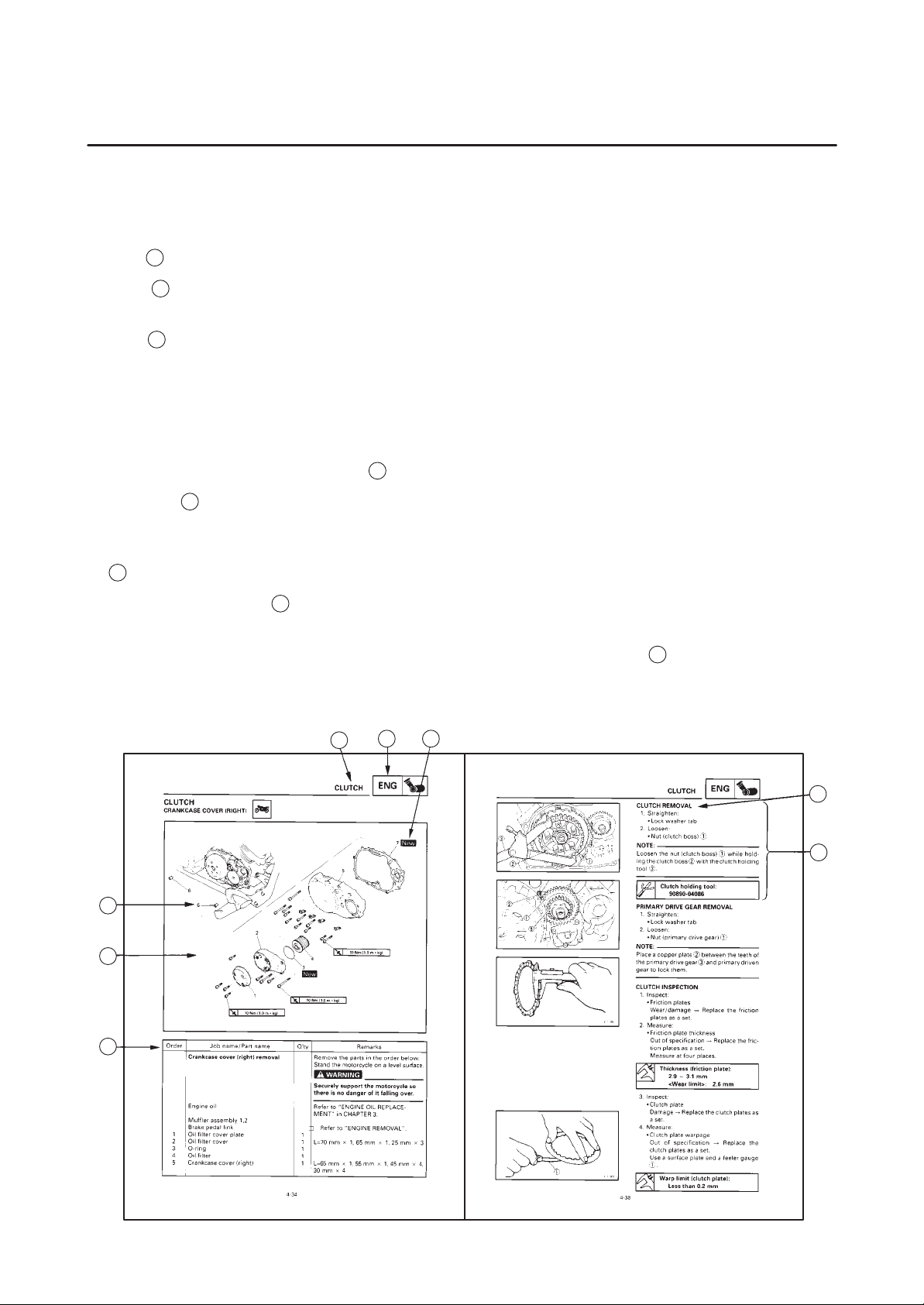
EXPLODED DIAGRAMS
T o help identify parts and clarify procedure steps, there are exploded diagrams at the start of each removal and disassembly section.
1. An easy-to-see exploded diagram
4
is provided for removal and disassembly jobs.
2. Numbers 5 are given in the order of the jobs in the exploded diagram. A number that is enclosed by
a circle indicates a disassembly step.
3. An explanation of jobs and notes is presented in an easy-to-read way by the use of symbol marks
6
. The meanings of the symbol marks are given on the next page.
7
4. A job instruction chart
accompanies the exploded diagram, providing the order of jobs, names of
parts, notes in jobs, etc.
8
5. For jobs requiring more information, the step-by-step format supplements
are given in addition to
the exploded diagram and the job instruction chart.
1
2
5
4
7
6
3
8
Page 5
EB003000
1
2
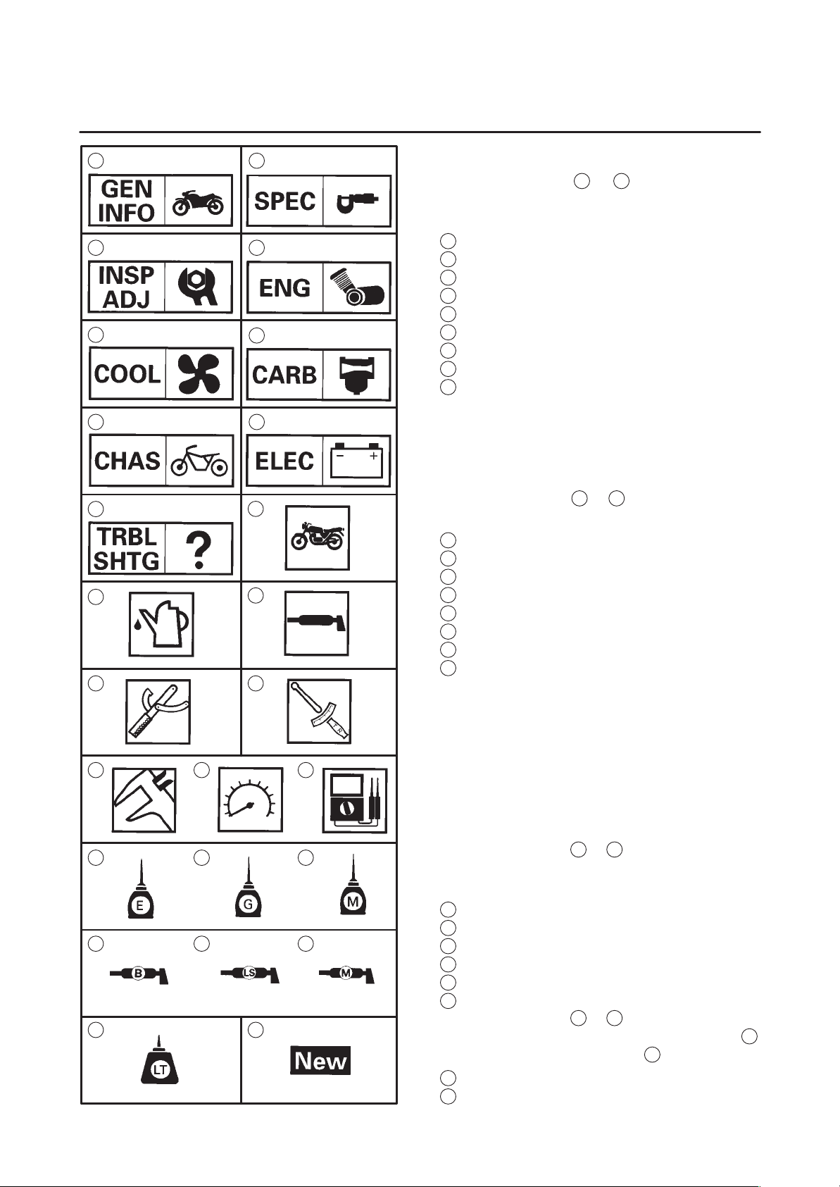
ILLUSTRATED SYMBOLS
Illustrated symbols 1 to 9 are printed on the
top right of each page and indicate the subject of
each chapter.
General information
3
5
4
6
1
Specifications
2
Periodic inspections and adjustments
3
Engine
4
Cooling system
5
Carburetion
6
Chassis
7
Electrical
8
Troubleshooting
9
7
9
11
13
15 16 17
8
10
12
14
Illustrated symbols 10 to 17 are used to identify
the specifications appearing in the text.
10
Can be serviced with engine mounted
11
Filling fluid
12
Lubricant
13
Special tool
14
Torque
15
Wear limit, clearance
16
Engine speed
17
Ω, V, A
18
21
24
E004000
19 20
22 23
25
Illustrated symbols 18 to 23 in the exploded diagrams indicate the types of lubricants and lubrication points.
18
Apply engine oil
19
Apply gear oil
20
Apply molybdenum disulfide oil
21
Apply wheel bearing grease
22
Apply lightweight lithium-soap base grease
23
Apply molybdenum disulfide grease
Illustrated symbols 24 to 25 in the exploded diagrams indicate where to apply locking agent
24
and when to install new parts 25.
24
Apply locking agent (LOCTITE)
25
Replace
Page 6
CHAPTER TITLES
GENERAL INFORMATION
SPECIFICATIONS
PERIODIC INSPECTION AND
ADJUSTMENTS
ENGINE OVERHAUL
CARBURETION
GEN
INFO
SPEC
INSP
ADJ
ENG
CARB
1
2
3
4
5
CHASSIS
ELECTRICAL
TROUBLESHOOTING
CHAS
ELEC
TRBL
SHTG
6
7
8
Page 7
GEN
INFO
1
Page 8

GEN
INFO
CHAPTER 1.
GENERAL INFORMATION
MOTORCYCLE IDENTIFICATION 1-1. . . . . . . . . . . . . . . . . . . . . . . . . . . . . . .
VEHICLE IDENTIFICATION NUMBER 1-1. . . . . . . . . . . . . . . . . . . . . . . . .
MODEL LABEL 1-1. . . . . . . . . . . . . . . . . . . . . . . . . . . . . . . . . . . . . . . . . . . . .
IMPORTANT INFORMATION 1-2. . . . . . . . . . . . . . . . . . . . . . . . . . . . . . . . . . . .
PREPARATION FOR REMOVAL PROCEDURES 1-2. . . . . . . . . . . . . . .
REPLACEMENT PARTS 1-2. . . . . . . . . . . . . . . . . . . . . . . . . . . . . . . . . . . . .
GASKETS, OIL SEALS AND O-RINGS 1-2. . . . . . . . . . . . . . . . . . . . . . . .
LOCK WASHERS/PLATES AND COTTER PINS 1-3. . . . . . . . . . . . . . . .
BEARINGS AND OIL SEALS 1-3. . . . . . . . . . . . . . . . . . . . . . . . . . . . . . . . .
CIRCLIPS 1-3. . . . . . . . . . . . . . . . . . . . . . . . . . . . . . . . . . . . . . . . . . . . . . . . . .
CHECKING OF CONNECTIONS 1-4. . . . . . . . . . . . . . . . . . . . . . . . . . . . . . . . .
SPECIAL TOOLS 1-5. . . . . . . . . . . . . . . . . . . . . . . . . . . . . . . . . . . . . . . . . . . . . .
Page 9
MOTORCYCLE IDENTIFICATION
EB100000
GENERAL INFORMATION
MOTORCYCLE IDENTIFICATION
EB100010
VEHICLE IDENTIFICATION NUMBER
The vehicle identification number
into the right side of the steering head.
MODEL LABEL
The model label
information will be needed to order spare parts.
1
is affixed to the frame. This
GEN
INFO
1
is stamped
1-1
Page 10
IMPORTANT INFORMATION
EB101000
IMPORTANT INFORMATION
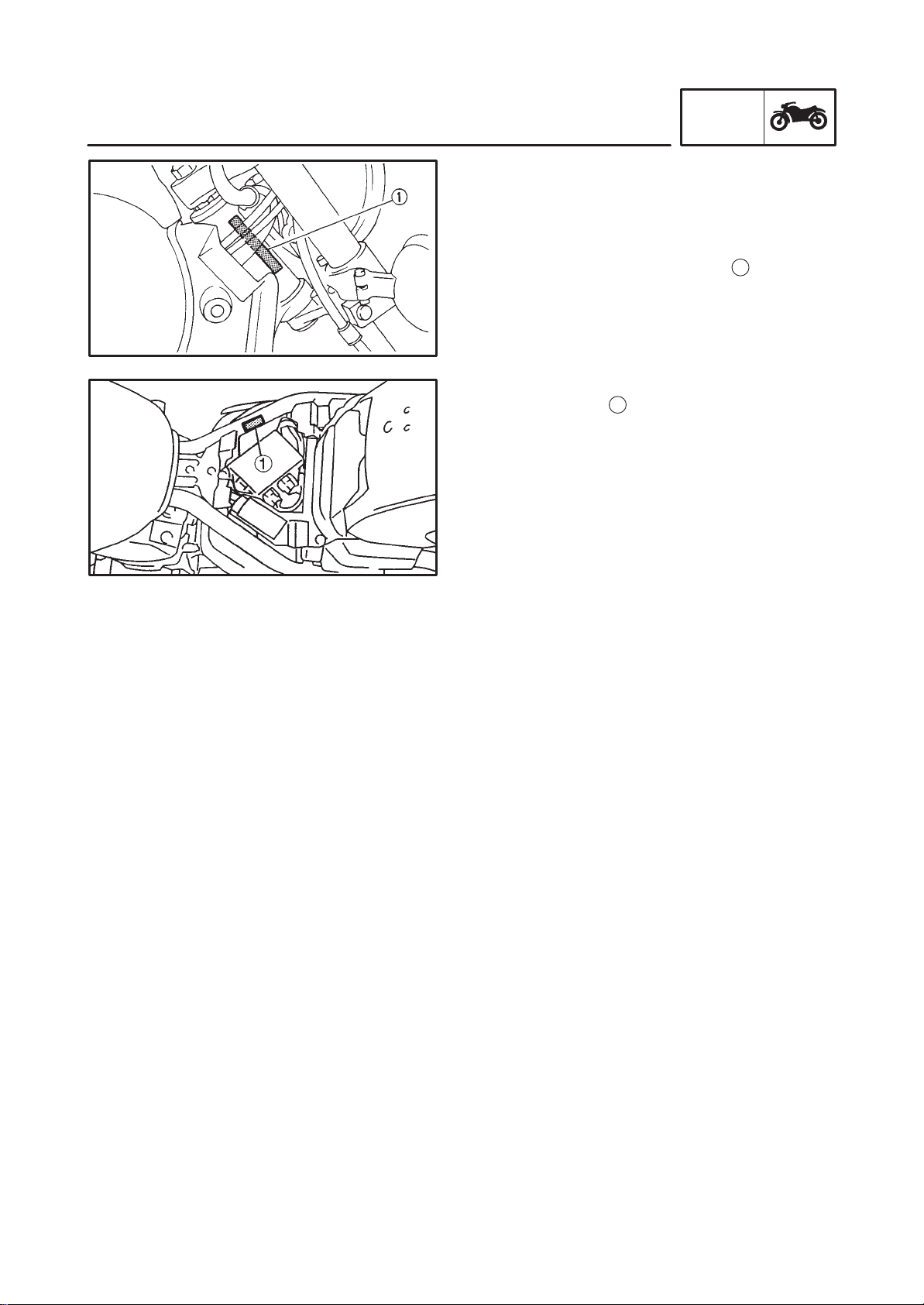
PREPARATION FOR REMOVAL PROCEDURES
1. Remove all dirt, mud, dust and foreign material before removal and disassembly.
2. Use proper tools and cleaning equipment.
Refer to the “SPECIAL TOOLS” section.
3. When disassembling the machine, always
keep mated parts together. This includes
gears, cylinders, pistons and other parts that
have been “mated” through normal wear.
Mated parts must always be reused or replaced as an assembly.
4. During machine disassembly , clean all parts
and place them in trays in the order of disassembly . This will speed up assembly and allow for the correct installation of all parts.
5. Keep all parts away from any source of fire.
GEN
INFO
EB101010
REPLACEMENT PARTS
1. Use only genuine Yamaha parts for all replacements. Use oil and grease recommended by Yamaha for all lubrication jobs.
Other brands may be similar in function and
appearance, but inferior in quality.
EB101020
GASKETS, OIL SEALS AND O-RINGS
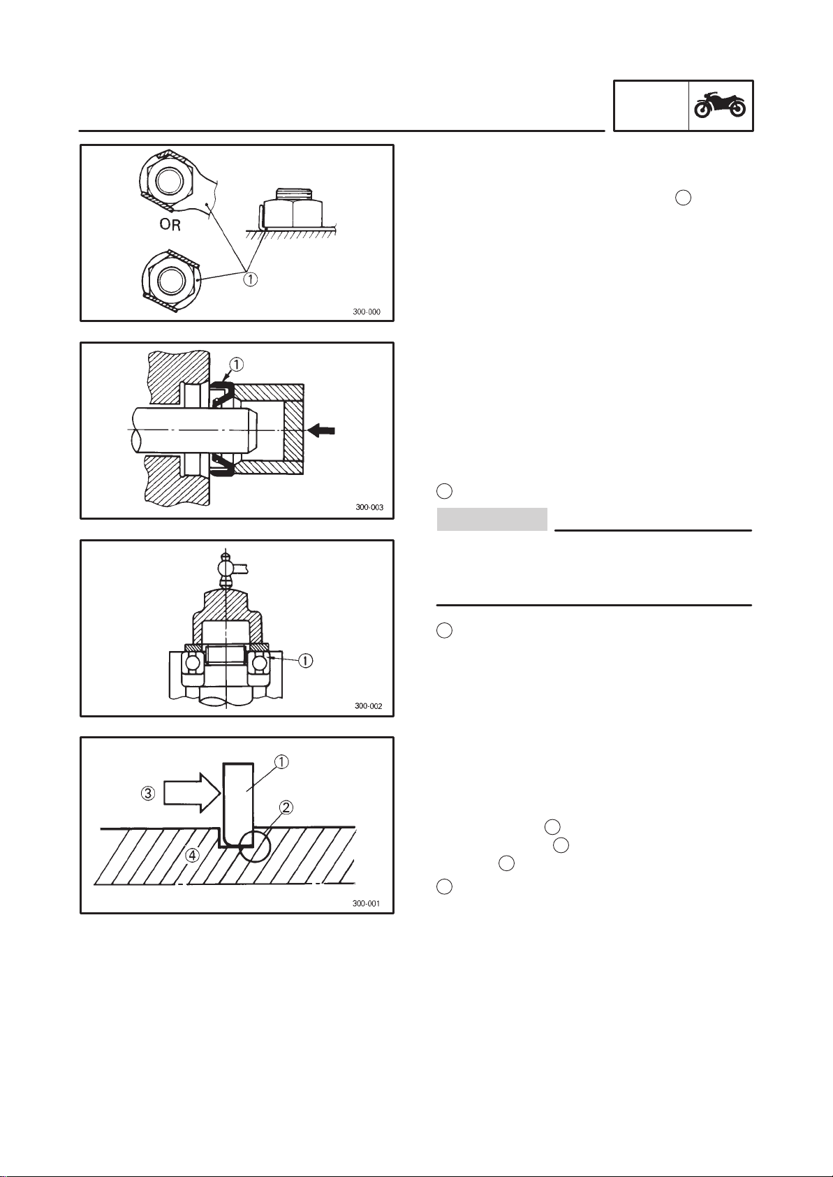
1. Replace all gaskets, seals and O-rings when
overhauling the engine. All gasket surfaces,
oil seal lips and O-rings must be cleaned.
2. Properly oil all mating parts and bearings
during reassembly. Apply grease to the oil
seal lips.
1-2
Page 11
IMPORTANT INFORMATION
EB101030
LOCK WASHERS/PLATES AND COTTER
PINS
1. Replace all lock washers/plates
ter pins after removal. Bend lock tabs along
the bolt or nut flats after the bolt or nut has
been tightened to specification.
EB101040
BEARINGS AND OIL SEALS
1. Install bearings and oil seals so that the
manufacturer’s marks or numbers are visible. When installing oil seals, apply a light
coating of lightweight lithium base grease to
the seal lips. Oil bearings liberally when
installing, if appropriate.
Oil seal
1
GEN
INFO
1
and cot-
CAUTION:
Do not use compressed air to spin the bearings dry. This will damage the bearing surfaces.
Bearing
1
EB101050
CIRCLIPS
1. Check all circlips carefully before reassembly. Always replace piston pin clips after one
use. Replace distorted circlips. When installing a circlip
edged corner
thrust
Shaft
4
3
1
, make sure that the sharp-
2
is positioned opposite the
it receives. See sectional view.
1-3
Page 12
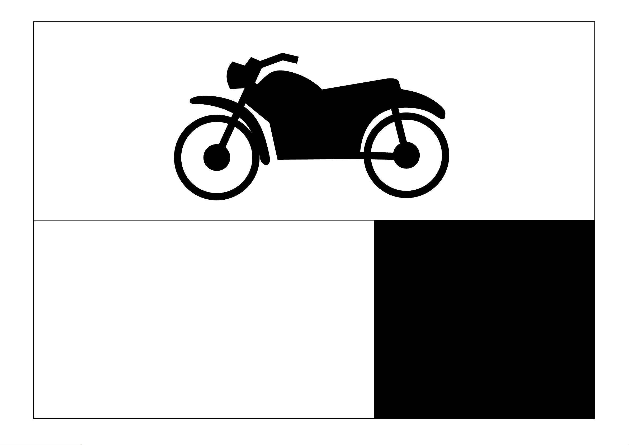
CHECKING OF CONNECTIONS
EB801000
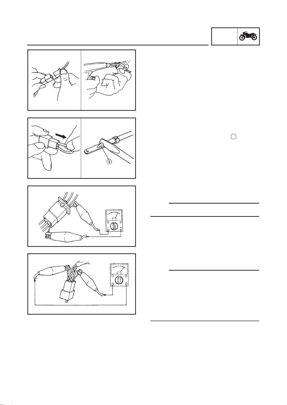
CHECKING OF CONNECTIONS
Check the connectors for stains, rust, moisture,
etc.
1. Disconnect:
Connector
2. Check:
Connector
Moisture Dry each terminal with an air
blower.
Stains/rust Connect and disconnect the
terminals several times.
3. Check:
Connector leads
Looseness Bend up the pin
nect the terminals.
GEN
INFO
1
and con-
4. Connect:
Connector terminals
NOTE:
The two terminals “click” together.
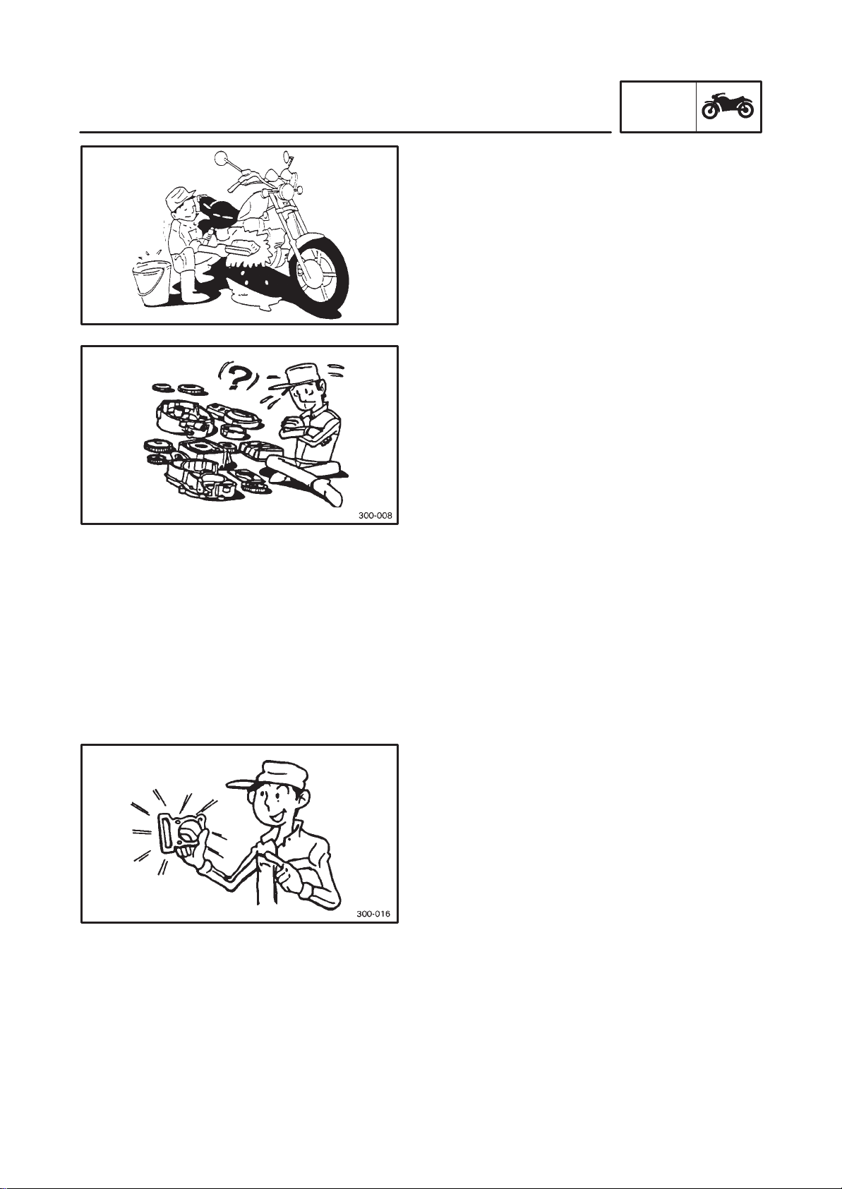
5. Check:
Continuity (using a pocket tester)
NOTE:
If there is no continuity, clean the terminals.
When checking the wire harness be sure to
perform steps 1 to 3.
As a quick remedy, use a contact revitalizer
available at most part stores.
Check the connector with a pocket tester as
shown.
1-4
Page 13
GEN
90890 01275
SPECIAL TOOLS
EB102001
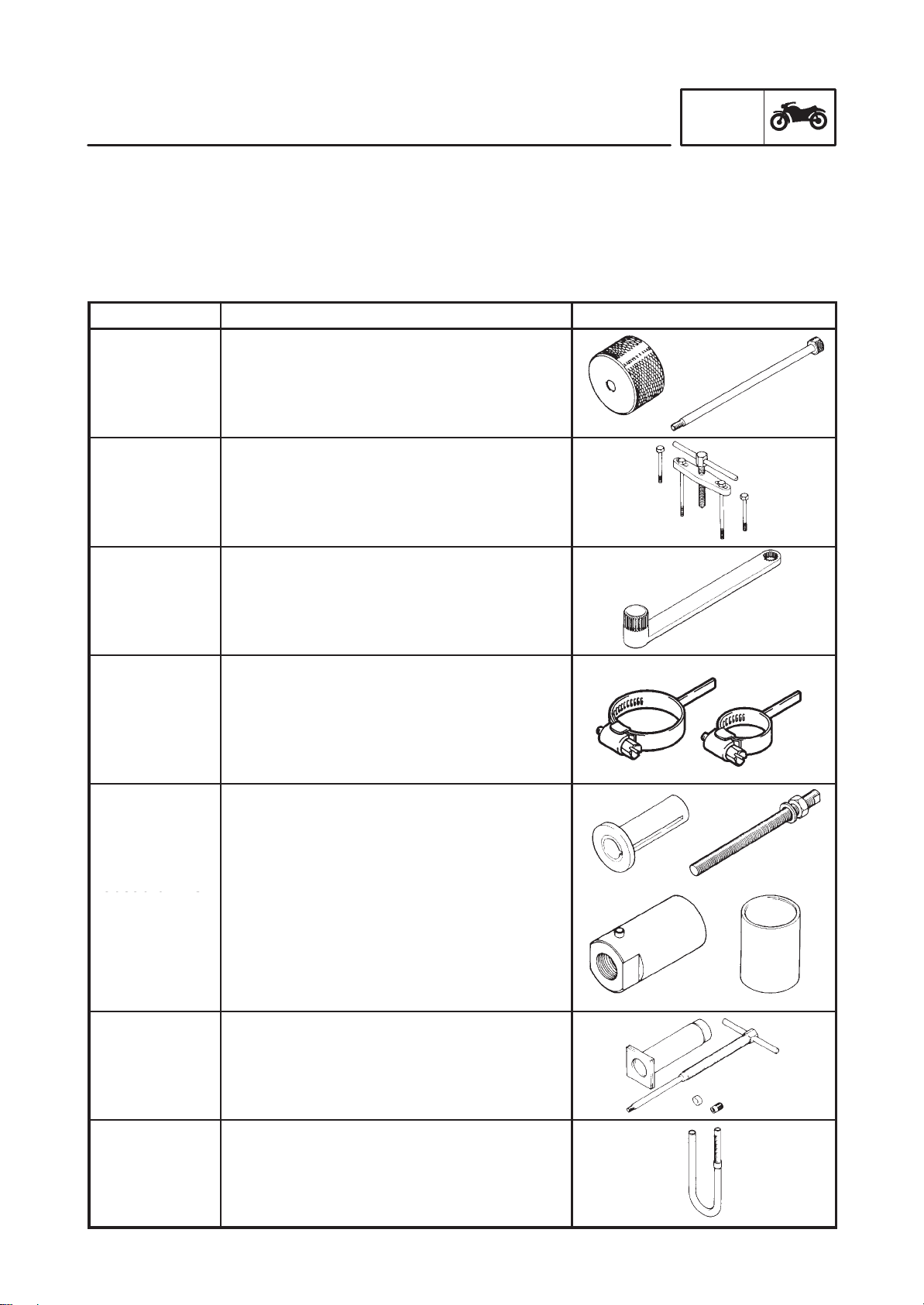
SPECIAL TOOLS
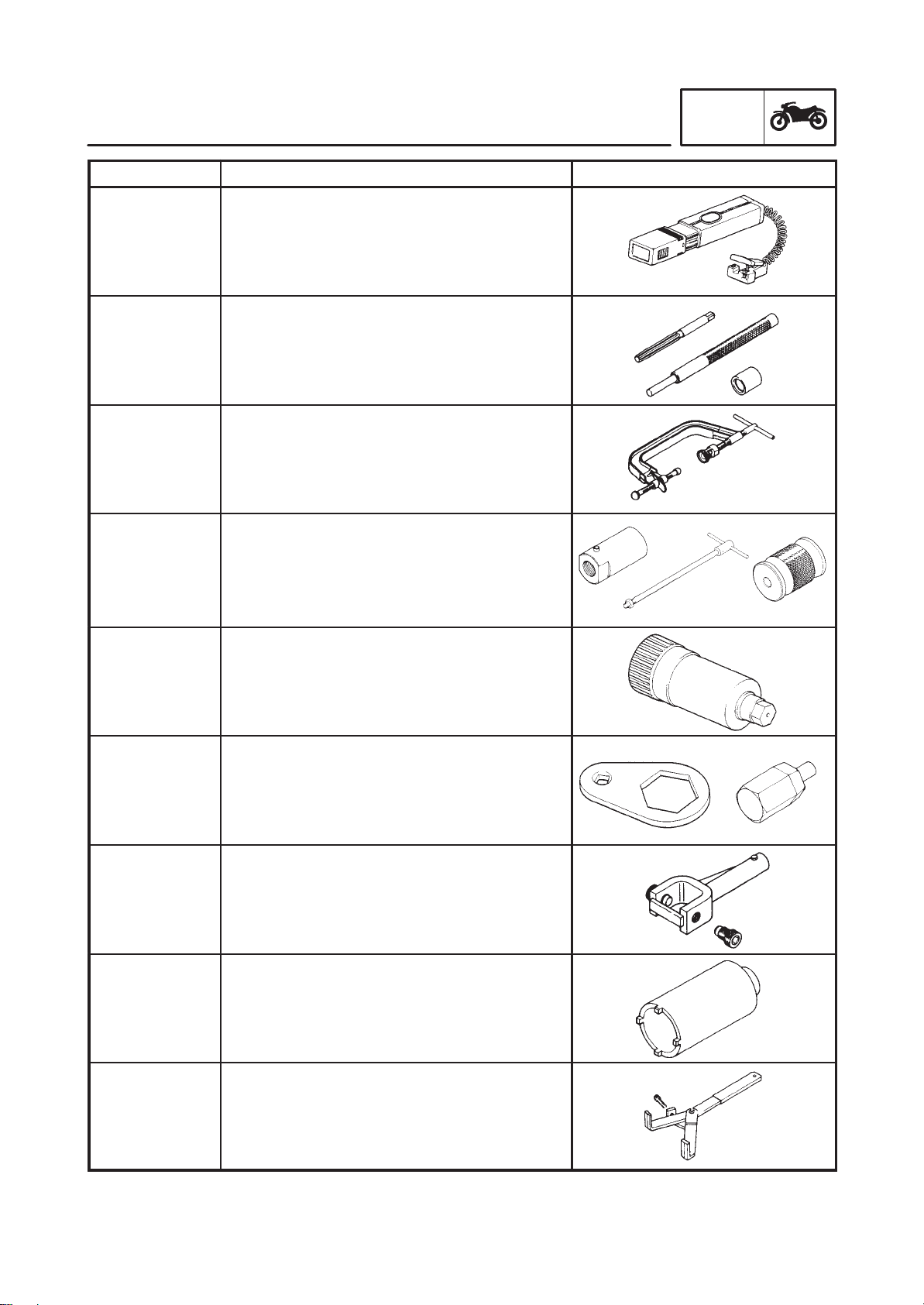
The following special tools are necessary for complete and accurate tune-up and assembly . Use only
the appropriate special tools; this will help prevent damage caused by the use of inappropriate tools or
improvised techniques. Special tools may differ by shape and part number from country to country . In
such a case, two types are provided.
When placing an order, refer to the list provided below to avoid any mistakes.
INFO
Tool No.
Weight
90890-01084
Bolt
90890-01085
90890-01135
90890-01229
Final gear
backlash band
90890-01230
Middle gear
backlash band
90890-01231
Tool name/How to use Illustration
Slide hammer bolt/weight
These tools are used to remove the rocker
arm shaft.
Crankcase separating tool
This tool is used to remove the crankshaft.
Coupling gear/Middle shaft tool
This tool is needed when removing or
installing the final pinion shaft nut.
Final gear backlash band
This tool is needed when measuring final gear
/middle gear backlash.
Crankshaft installer pot/bolt/adapter/spacer
Installer pot
90890-01274
Bolt
90890-01275
Adaptor
90890-04130
Spacer
90890-04060
These tools are used to install the crankshaft.
Piston pin puller
90890-01304
This tool is used to remove the piston pin.
Fuel level gauge
90890-01312
This gauge is used to measure the fuel level
in the float chamber.
1-5
Page 14
GEN
SPECIAL TOOLS
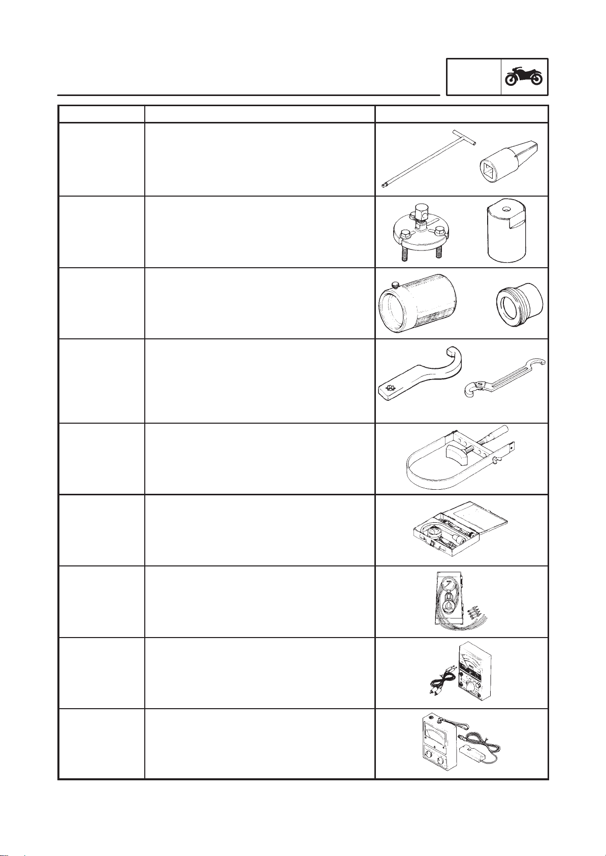
Tool No. Tool name/How to use Illustration
INFO
T-handle
90890-01326
Holder
90890-01460
Puller
90890-01362
Adapter
90890-04131
Weight
90890-01367
Adapter
90890-01381
Ring nut wrench
90890-01403
Exhaust nut
wrench
90890-01268
T-handle/damper rod holder
These tools are needed to loosen and tighten
the damper rod holding bolt.
Flywheel puller/adapter
These tools are needed to remove the rotor.
Fork seal driver weight/adapter
These tools are needed when installing the
slide metal, oil seal and dust seal into the fork.
Ring nut wrench/ehaust and steering nut
wrench
This tool is needed to loosen and tighten the
steering stem ring nut.
90890-01701
90890-03081
90890-03094
90890-031 12
Sheave holder
This tool is needed to hold the rotor when removing or installing the rotor bolt.
Compression gauge set
These tools are needed to measure engine
compression.
Vacuum gauge
This gauge is needed for carburetor synchronization.
Pocket tester
This instrument is needed for checking the
electrical system.
Engine tachometer
90890-03113
This tool is needed for observing engine r/min.
1-6
Page 15
GEN
SPECIAL TOOLS
Tool No. Tool name/How to use Illustration
Timing light
90890-03141
This tool is necessary for checking ignition
timing.
Valve guide remover & installer
90890-04014
This tool is needed to remove and install the
valve guide.
Valve spring compressor
90890-04019
This tool is needed to remove and install the
valve assemblies.
INFO
Adapter
90890-01277
Shock puller
90890-01290
Weight
90890-01291
90890-04137
Wrench
90890-04138
Holder
90890-04055
90890-04062
Crankshaft installer bolt adapter/armature
shock puller/weight
These tools are needed when removing the
final pinion shaft.
Bearing retainer wrench
This tool is needed when removing or installing the middle drive shaft assembly.
Middle drive shaft nut wrench/Middle drive
shaft holder
These tools are needed when removing or
installing the middle drive shaft bearing.
Universal joint holder
This tool is needed when removing or installing the driven pinion gear nut.
Bearing retainer wrench
90890-04077
90890-04086
This tool is needed when removing or installing the final drive pinion gear assembly.
Clutch holding tool
This tool is needed to hold the clutch when removing or installing the clutch boss nut.
1-7
Page 16
GEN
SPECIAL TOOLS
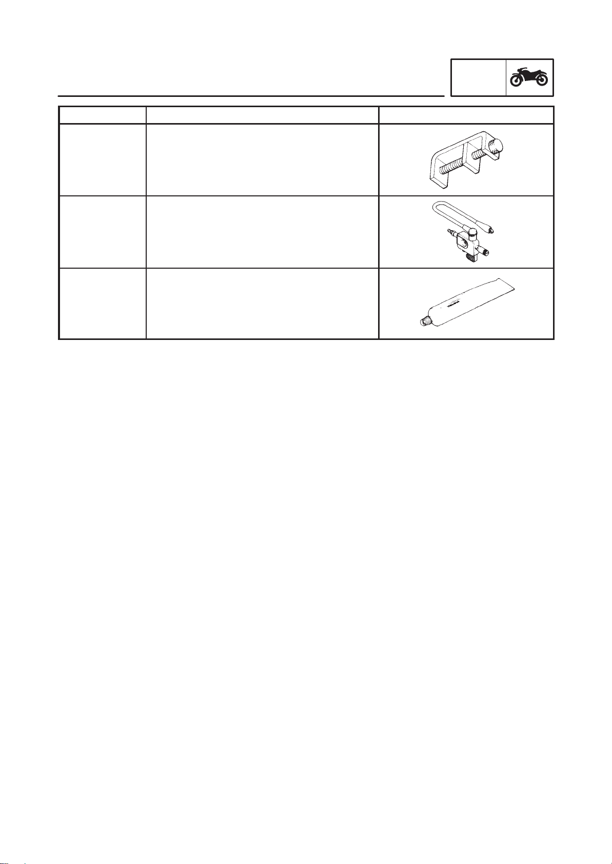
Tool No. Tool name/How to use Illustration
Damper spring compressor
90890-04090
This tool is needed when removing or installing the damper spring.
Dynamic spark tester
Ignition checker
90890-06754
This instrument is necessary for checking the
ignition system components.
Yamaha bond No.1215
90890-85505
This sealant (bond) is used on crankcase mating surfaces, etc.
INFO
1-8
Page 17

SPEC
2
Page 18

SPEC
CHAPTER 2.
SPECIFICATIONS
GENERAL SPECIFICATIONS 2-1. . . . . . . . . . . . . . . . . . . . . . . . . . . . . . . . . . .
MAINTENANCE SPECIFICATIONS 2-4. . . . . . . . . . . . . . . . . . . . . . . . . . . . . .
ENGINE 2-4. . . . . . . . . . . . . . . . . . . . . . . . . . . . . . . . . . . . . . . . . . . . . . . . . . .
CHASSIS 2-14. . . . . . . . . . . . . . . . . . . . . . . . . . . . . . . . . . . . . . . . . . . . . . . . . .
ELECTRICAL 2-18. . . . . . . . . . . . . . . . . . . . . . . . . . . . . . . . . . . . . . . . . . . . . .
GENERAL TORQUE SPECIFICATIONS 2-20. . . . . . . . . . . . . . . . . . . . . . . . . .
CONVERSION TABLE 2-20. . . . . . . . . . . . . . . . . . . . . . . . . . . . . . . . . . . . . . . . . .
LUBRICATION POINTS AND LUBRICANT TYPES 2-21. . . . . . . . . . . . . . . .
ENGINE 2-21. . . . . . . . . . . . . . . . . . . . . . . . . . . . . . . . . . . . . . . . . . . . . . . . . . .
CHASSIS 2-22. . . . . . . . . . . . . . . . . . . . . . . . . . . . . . . . . . . . . . . . . . . . . . . . . .
E
LUBRICATION DIAGRAMS 2-23. . . . . . . . . . . . . . . . . . . . . . . . . . . . . . . . . . . . .
CABLE ROUTING 2-26. . . . . . . . . . . . . . . . . . . . . . . . . . . . . . . . . . . . . . . . . . . . .
Page 19
GENERAL SPECIFICATIONS
GENERAL SPECIFICATIONS
SPECIFICATIONS
SPEC
Item
Model code: XVS1100: 5EL1 (For Europe)
5EL2 (For D, A, FIN)
5EL3 (For Australia)
Dimensions:
Overall length
Overall width
Overall height
Seat height
Wheelbase
Minimum ground clearance
Minimum turning radius
Basic weight:
With oil and a full fuel tank
Engine:
Engine type
Cylinder arrangement
Displacement
Bore stroke
Compression ratio
Compression pressure (STD)
Starting system
2,405 mm
895 mm
1,095 mm
690 mm
1,640 mm
145 mm
3,200 mm
274 kg (5EL2 : 275kg)
Air cooled 4-stroke, SOHC
V-type 2-cylinder
1.063 L
95 75mm
8.3 : 1
1,000 kPa (10 kg/cm
Electric starter
Standard
2
, 10 bar) at 400 r/min
Lubrication system: Wet sump
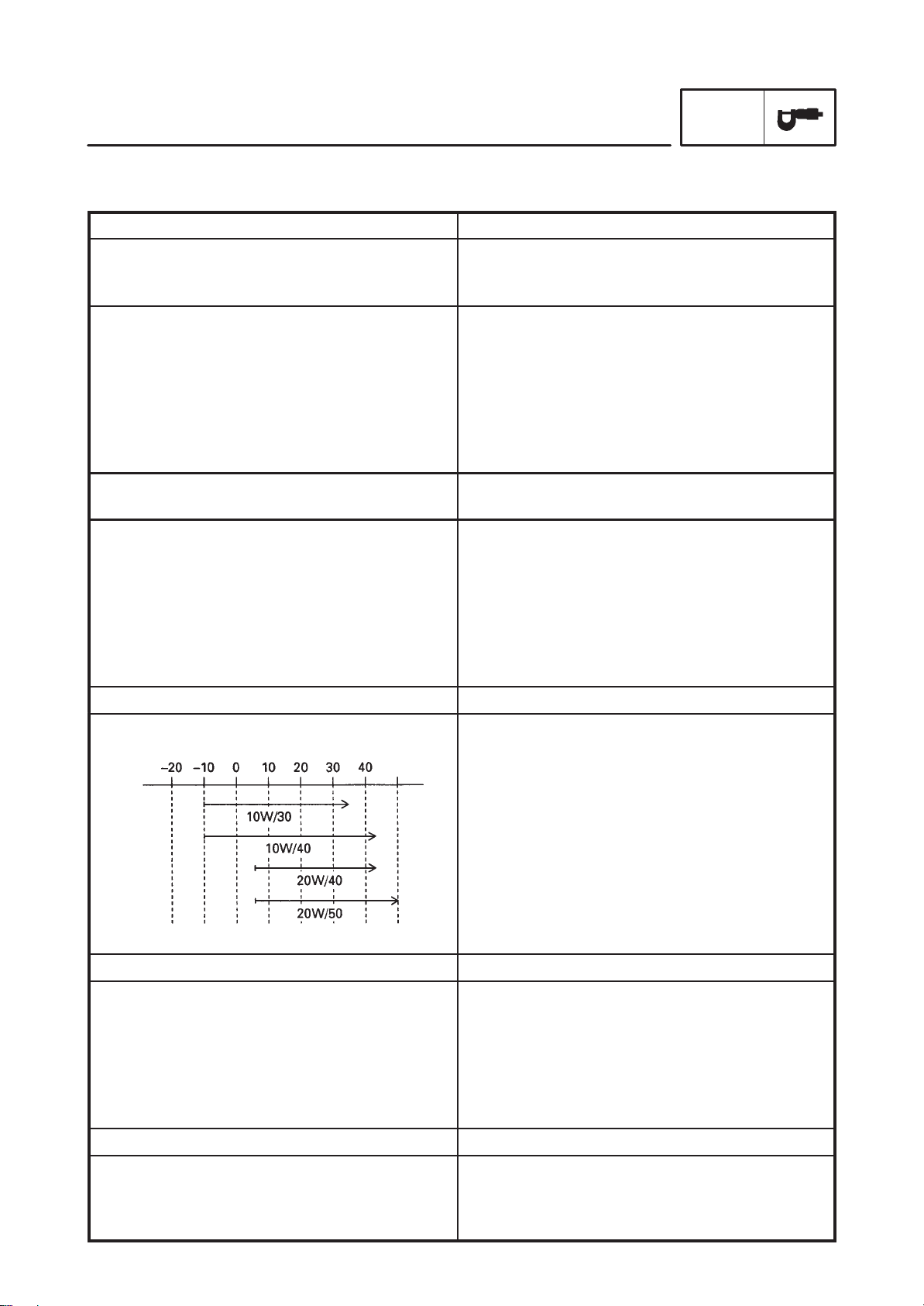
Oil type or grade:
Engine oil
Final gear oil: SAE80API “GL-4” Hypoid Gear Oil
Oil quantity:
Engine oil
Periodic oil change
With oil filter replacement
Total amount
Final gear case oil
Total amount
Air filter: Dry type element
Temp. C
API standard:
“SE” or higher grade
ACEA standard:
G4 or G5
3.0 L
3.1 L
3.6 L
0.2 L
Fuel:
Type
Fuel tank capacity
Fuel reserve amount
Regular unleaded gasoline
17 L
4.5 L
2-1
Page 20
GENERAL SPECIFICATIONS
Item Standard
Carburetor:
Type/quantity
Manufacturer
Spark plug:
Type
Manufacturer
Spark plug gap
Clutch type: Wet, multiple-disc
Transmission:
Primary reduction system
Primary reduction ratio
Secondary reduction system
Secondary reduction ratio
Transmission type
Operation
Gear ratio 1st
2nd
3rd
4th
5th
Chassis:
Frame type
Caster angle
Trail
Tire:
Type
Size front
rear
Manufacturer front
rear
Type front
rear
Maximum load-except motorcycle: 201 kg (5EL2 : 200kg)
BSR37/2
MIKUNI
BPR7ES/W22EPR–U
NGK/DENSO
0.7 X 0.8 mm
Spur gear
78/47 (1.660)
Shaft drive
44/47 19/18 32/11 (2.875)
Constant mesh 5-speed
Left foot operation
40/17 (2.353)
40/24 (1.667)
36/28 (1.286)
32/31 (1.032)
29/34 (0.853)
Double cradle
33
136 mm
With tube
110/90-18 61S
170/80-15M/C 77S
BRIDGESTONE/DUNLOP
BRIDGESTONE/DUNLOP
EXEDRA L309/K555F
EXEDRA G546/K555
SPEC
Tire pressure (cold tire):
0 X 90 kg (0 X 198 lb) load *
front
rear
90 kg (198 lb) X Maximum load *
front
rear
Brake:
Front brake type
operation
Rear brake type
operation
200 kPa (2.00 kg/cm2)
2
225 kPa (2.25 kg/cm
225 kPa (2.25 kg/cm
250 kPa (2.50 kg/cm2)
* Load is the total weight of the cargo, rider,
passenger and accessories.
Dual disc brake
Right hand operation
Single disc brake
Right foot operation
2-2
)
2
)
Page 21
GENERAL SPECIFICATIONS
Item Standard
Suspension:
Front suspension
Rear suspension
Shock absorber:
Front shock absorber
Rear shock absorber
Wheel travel:
Front wheel travel
Rear wheel travel
Electrical:
Ignition system
Generator system
Battery type
Battery capacity
Headlight type: Quartz bulb (halogen)
Bulb wattage quantity:
Headlight
Auxiliary light
Tail/brake light
Turn signal
Licence light
Meter light
Neutral indicator light
High beam indicator light
Turn indicator light
Oil level caution light
Engine warning light
Telescopic fork
Swingarm (link suspension)
Coil spring/Oil damper
Coil spring/Gas-oil damper
140 mm
113 mm
T.C.I. (digital)
A.C. magneto
GT14B-4
12 V 12 AH
12 V 60 W/55 W 1
12 V 4 W 1
12 V 5 W/21 W 1
12 V 21 W 4
12 V 5 W 1
14 V 1.4 W 2
12 V 1.7 W 1
12 V 1.7 W 1
12 V 1.7 W 1
12 V 1.7 W 1
12 V 1.7 W 1
SPEC
2-3
Page 22
MAINTENANCE SPECIFICATIONS
MAINTENANCE SPECIFICATIONS
ENGINE
SPEC
Item
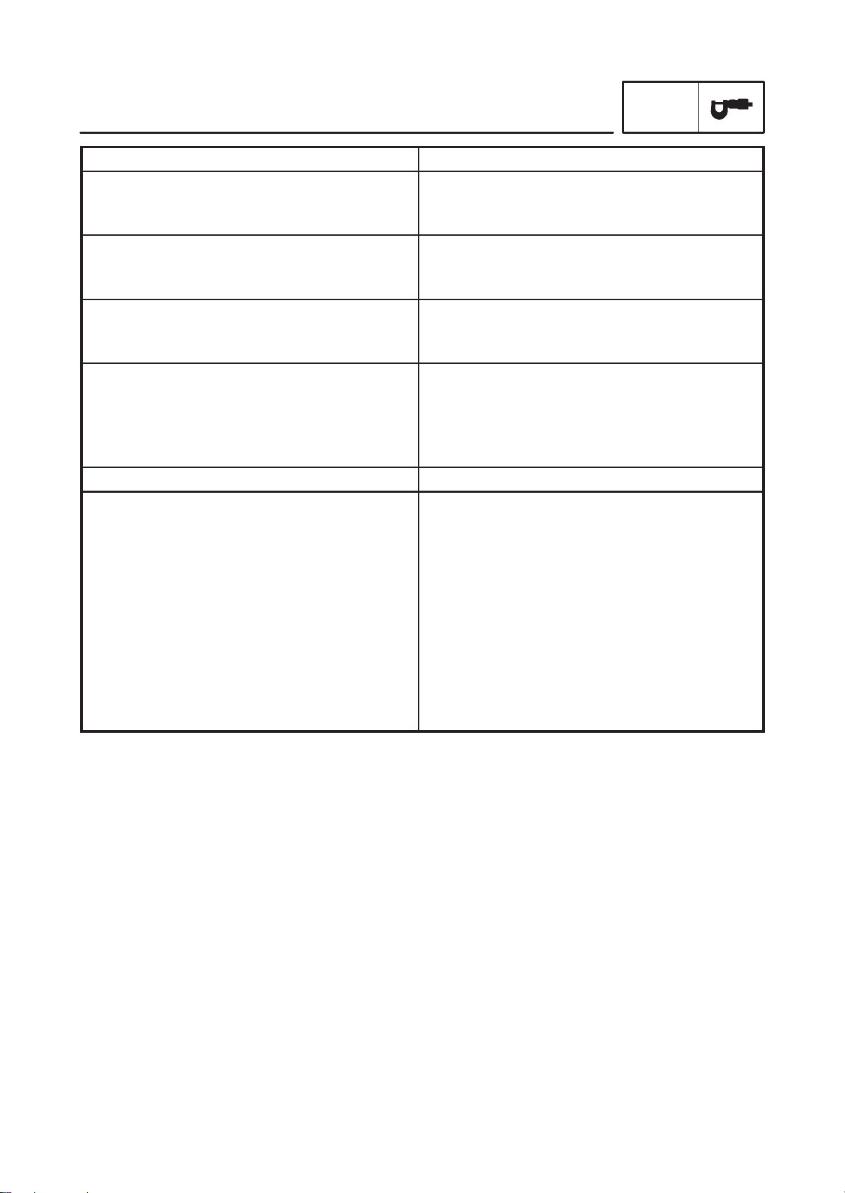
Cylinder head:
Warp limit
Cylinder:
Bore size
Measuring point
Camshaft:
Drive method
Cam cap inside diameter
Camshaft outside diameter
Shaft-to-cap clearance
Cam dimensions
Standard Limit
SSS 0.03 mm
95.00 X 95.01 mm
40 mm
Chain drive (left & right)
25.000 X 25.021 mm
24.96 X 24.98 mm
0.020 X 0.061 mm
95.1 mm
SSS
SSS
SSS
SSS
SSS
Intake “A”
“B”
“C”
Exhaust “A”
“B”
“C”
Camshaft runout limit
39.112 X 39.212 mm
#1: 32.093 X 32.193 mm
#2: 32.127 X 32.227 mm
7.162 mm
39.145 X 39.245 mm
32.200 X 32.300 mm
7.195 mm
SSS
2-4
39.012 mm
#1: 31.993 mm
#2: 32.027 mm
7.012 mm
39.045 mm
32.100 mm
7.045 mm
0.03 mm
Page 23
Item Standard Limit
Timing chain:
Timing chain type/No. of links
Timing chain adjustment method
Rocker arm/rocker arm shaft:
Bearing inside diameter
Shaft outside diameter
Arm-to-shaft clearance
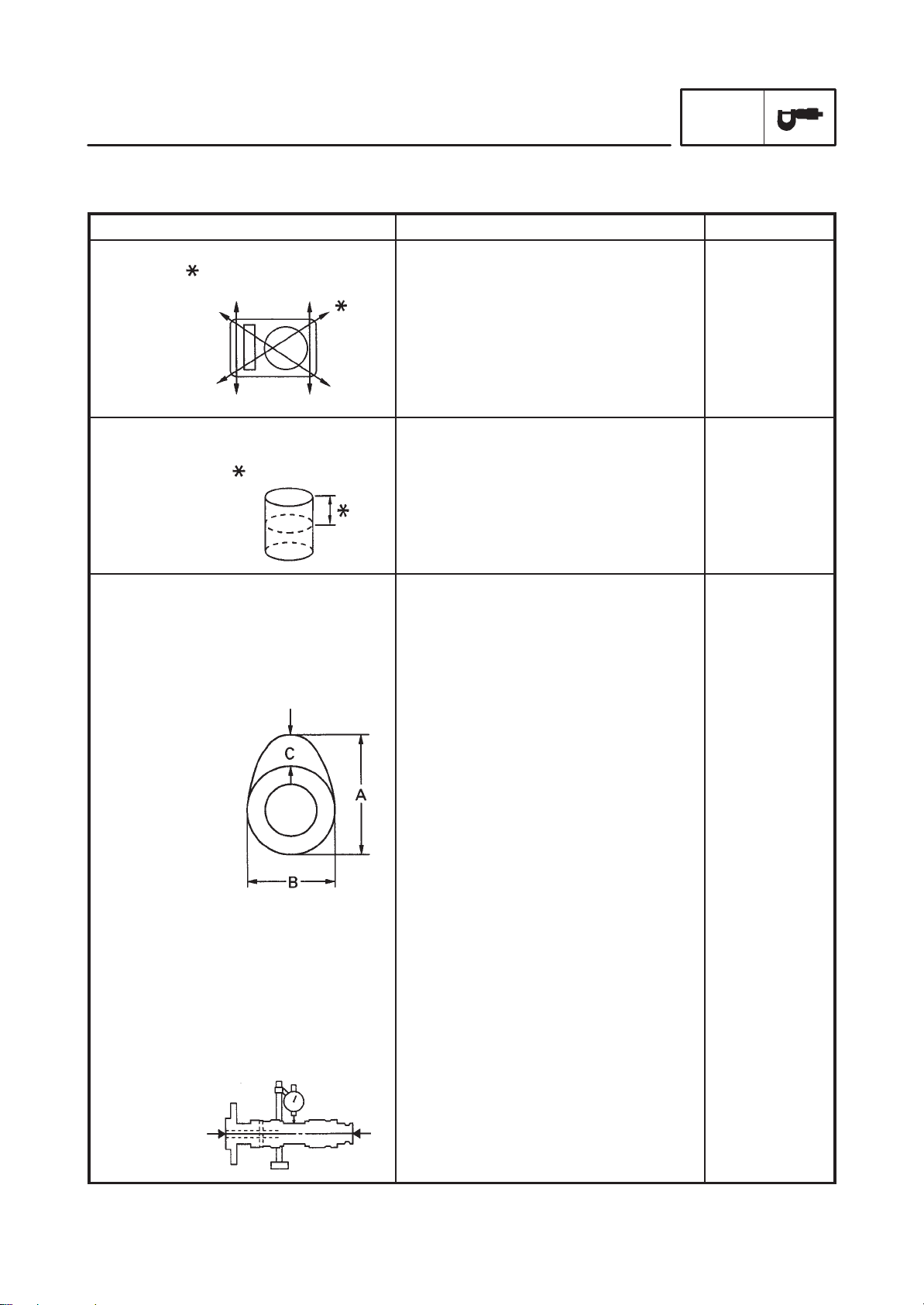
Valve, valve seat, valve guide:
Valve clearance (cold) IN
Valve dimensions:
MAINTENANCE SPECIFICATIONS
SILENT CHAIN/98L
Automatic
14.000 mm X 14.018 mm
13.985 mm X 13.991 mm
0.009 mm X 0.033 mm
0.07 X 0.12 mm
EX
0.12 X 0.17 mm
SPEC
SSS
SSS
14.036 mm
13.95 mm
0.086 mm
SSS
SSS
Head Dia Face width Seat Width
“A” head diameter IN
EX
“B” face width IN
EX
“C” seat width IN
EX
“D” margin thickness IN
EX
Stem outside diameter IN
EX
Guide inside diameter IN
EX
Stem-to-guide clearance IN
EX
47.0 X 47.2 mm
39.0 X 39.2 mm
2.1 mm
2.1 mm
1.2 X 1.4 mm
1.2 X 1.4 mm
1.1 X 1.5 mm
1.1 X 1.5 mm
7.975 X 7.990 mm
7.960 X 7.975 mm
8.000 X 8.012 mm
8.000 X 8.012 mm
0.010 X 0.037 mm
0.025 X 0.052 mm
Margin Thickness
SSS
SSS
SSS
SSS
1.8 mm
1.8 mm
0.8 mm
0.8 mm
SSS
SSS
SSS
SSS
0.08 mm
0.10 mm
2-5
Page 24
MAINTENANCE SPECIFICATIONS
Item Standard Limit
SPEC
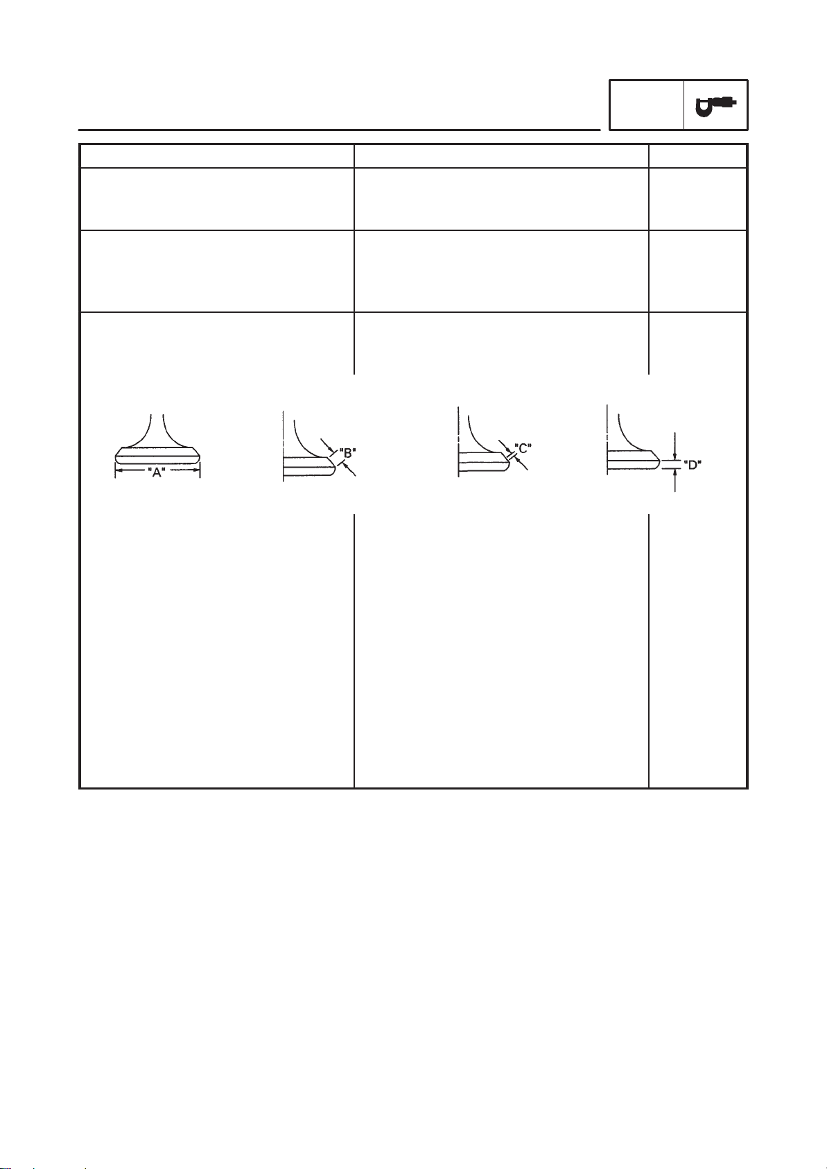
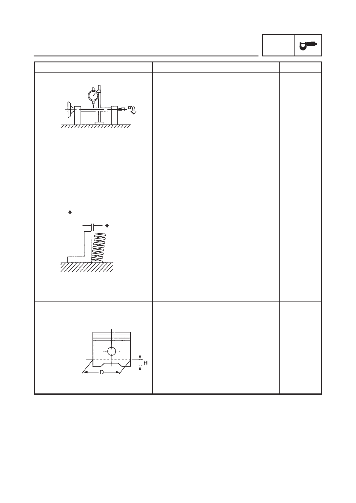
Stem runout limit
Valve seat width IN
Valve spring:
Free length IN
Set length (valve closed) IN
Compressed pressure IN
(installed) EX
Tilt limit IN
EX
EX
EX
EX
SSS
1.2 X 1.4 mm
1.2 X 1.4 mm
44.6 mm
44.6 mm
40 mm
40 mm
160.7 N (16.4 kg)
160.7 N (16.4 kg)
SSS
SSS
0.03 mm
2.0 mm
2.0 mm
43.5 mm
43.5 mm
SSS
SSS
SSS
SSS
2.5_ /1.9mm
2.5_ /1.9mm
Direction of winding
(top view) IN
Piston:
Piston to cylinder clearance
Piston size “D”
Measuring point “H”
Piston off-set
EX
Clockwise
Clockwise
0.025 X 0.050 mm
94.960 X 94.975 mm
5 mm
0 mm
SSS
SSS
0.15 mm
SSS
SSS
SSS
2-6
Page 25
MAINTENANCE SPECIFICATIONS
Item Standard Limit
SPEC
Piston pin bore inside diameter
Piston pin outside diameter
Piston rings:
Top ring:
Type
Dimensions (B T)
End gap (installed)
Side clearance (installed)
2nd ring:
Type
Dimensions (B T)
End gap (installed)
Side clearance
Oil ring:
22.004 X 22.015 mm
21.991 X 22.000 mm
Plain
1.5 3.8 mm
0.3 X 0.5 mm
0.04 X 0.08 mm
Taper
1.2 3.8 mm
0.30 X 0.45 mm
0.03 X 0.07 mm
SSS
SSS
SSS
SSS
0.8 mm
0.1 mm
SSS
SSS
0.8 mm
0.1 mm
Dimensions (B T)
End gap (installed)
Connecting rod:
Oil clearance
Color code (corresponding size)
Crankshaft:
Crank width “A”
Runout limit “C”
Big end side clearance “D”
2.5 3.4 mm
0.2 X 0.7 mm
0.044 X 0.073 mm
Blue Black Brown Green Yellow
1 2 3 4 5
101.95 X 102.00 mm
SSS
0.320 X 0.474 mm
SSS
SSS
SSS
SSS
SSS
0.02 mm
SSS
2-7
Page 26
MAINTENANCE SPECIFICATIONS
Item Standard Limit
Clutch:
Friction plate thickness
Quantity
Clutch plate thickness
Quantity
Clutch plate thickness
Quantity
Clutch spring free length
Quantity
Clutch housing thrust clearance
Clutch housing radial clearance
Clutch release method
Push rod bending limit
Transmission:
Main axle deflection limit
Drive axle deflection limit
Shifter:
Shifter type
Carburetor:
I. D. mark
Main jet (M.J)
Main air jet (M.A.J)
Jet needle (J.N)
Needle jet (N.J)
Pilot air jet (P.A.J.1)
(P.A.J.2)
Pilot outlet (P.O)
Pilot jet (P.J)
Bypass 1 (B.P.1)
Bypass 2 (B.P.2)
Bypass 3 (B.P.3)
Pilot screw (P.S)
Valve seat size (V.S)
Starter jet (G.S.1)
Starter jet (G.S.2)
Throttle valve size (Th.V)
Fuel level (F.L)
Engine idle speed
Intake vacuum
Engine oil temperature
SPEC
2.9 X 3.1 mm
8
2.5 X 2.7 mm
1
1.9 X 2.1 mm
7
7.2 mm
1
0.05 X 0.40 mm
0.010 X 0.044 mm
Inner push, screw push
SSS
SSS
SSS
Guide bar SSS
5EL1 00
#1: #110, #2: #112.5
#55
#1: 5DL39-53-3/5, #2: 5DL40-53-3/5
P-0M
#63.8
#145
1.0
#17.5
0.8
0.8
0.8
3
1.2
#42.5
0.8
#125
4X5 mm
950 X 1,050 r/min
34.7 X 37.3 kPa (260 X 280 mmHg)
75 X 85_C
2.8 mm
SSS
0.1 mm
SSS
0.1 mm
6.5 mm
SSS
SSS
SSS
SSS
0.5 mm
0.08 mm
0.08 mm
SSS
SSS
SSS
SSS
SSS
SSS
SSS
SSS
SSS
SSS
SSS
SSS
SSS
SSS
SSS
SSS
SSS
SSS
SSS
SSS
SSS
Fuel pump:
Type
Model/manufacturer
Consumption amperage <max>
Output pressure
Electrical type
UC-Z6M/MITSUBISHI
0.8 A
12 kPa (0.12 kg/cm
2-8
2
SSS
SSS
SSS
)
SSS
Page 27
Item Standard Limit
Lubrication system:
Oil filter type
Oil pump type
Tip clearance “A” or “B”
Side clearance
Relief valve operating pressure
Shaft drive:
Middle gear backlash
Final gear backlash
MAINTENANCE SPECIFICATIONS
Paper type
Trochoid type
0.03 X 0.09 mm
0.03 X 0.08 mm
450 X 550 kPa (4.5 X 5.5 kg/cm
0.1 X 0.2 mm
0.1 X 0.2 mm
2
)
SPEC
SSS
SSS
0.15 mm
0.15 mm
SSS
SSS
SSS
2-9
Page 28
Lubrication chart:
MAINTENANCE SPECIFICATIONS
Item Standard
SPEC
2-10
Page 29
MAINTENANCE SPECIFICATIONS
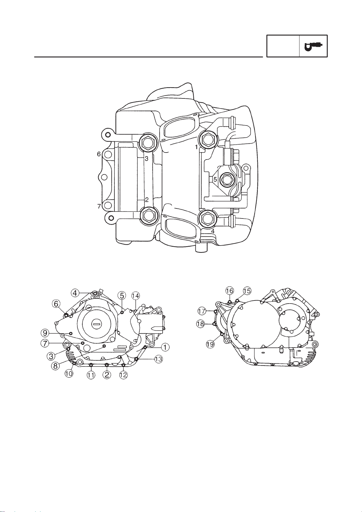
Cylinder head tightening sequence:
SPEC
Crankcase tightening sequence:
Left crankcase Right crankcase
2-11
Page 30
Tightening torques
g
size
y
MAINTENANCE SPECIFICATIONS
SPEC
Part to be tightened
Cylinder head
Cylinder head
Plate
Cylinder head cover
Cylinder head (exhaust pipe)
Rocker arm shaft
Camshaft sprocket cover
Tappet cover
Rocker arm shaft (oil passage)
Stopper plate (camshaft)
Spark plug
Cylinder
Lower cylinder head cover
Upper cylinder head cover
Connecting rod
Rotor
Valve adjusting locknut
Camshaft sprocket
Timing chain tensioner
Timing chain tentioner cap
Timing chain guide
Oil pump
Oil strainer cover
Oil filter cover
Oil pump gear
Oil pump cap
Oil deliuery pipe (cylinder head)
(crankcase)
Drain bolt
Carburetor cover
Air filter case stay
Air filter case assembly
Exhaust pipe joint and cylinder head
Exhaust pipe joint and muffler
assembly
Muffler
Crankcase (cylinder)
Crankcase (cylinder)
Crankcase
Crankcase
Bearing retainer (middle drive pinion
gear)
Crankcase cover (left)
Crankcase cover (right)
Clamp
One-way clutch
Primary drive gear
Part name
Nut
Nut
Bolt
Screw
Stud bolt
Union bolt
Bolt
Bolt
Bolt
Bolt
—
Bolt
Bolt
Screw
Nut
Nut
Nut
Bolt
Bolt
Bolt
Bolt
Bolt
Bolt
Bolt
Bolt
Bolt
Union bolt
Union bolt
—
Bolt
Bolt
Bolt
Nut
Bolt
Bolt
Stud bolt
Stud bolt
Bolt
Bolt
Bolt
Bolt
Bolt
Bolt
Bolt
Nut
Thread
M12
M10
M8
M6
M8
M16
M6
M6
M16
M8
M14
M6
M6
M6
M9
M16
M8
M10
M6
M6
M6
M6
M6
M6
M6
M6
M16
M10
M14
M5
M6
M5
M8
M8
M10
M12
M10
M10
M6
M8
M6
M6
M6
M6
M20
Q’ty
8
2
2
4
4
2
4
8
4
4
2
2
6
8
4
1
4
2
4
2
4
3
3
5
1
1
2
1
1
2
2
3
4
2
2
8
2
3
10
3
13
11
1
8
1
Tightening
torque
Nm mSkg
50
35
20
12.5
37.5
10
10
38
20
20
10
10
48
175
27
55
10
10
10
10
10
12
10
20
20
43
10
20
20
25
24
20
38.5
10
25
10
10
10
12
110
5.0
3.5
2.0
4
0.4
1.25
3.75
1.0
1.0
3.8
2.0
2.0
1.0
1.0
5
0.5
4.8
17.5
2.7
5.5
1.0
8
0.8
1.0
1.0
1.0
1.0
1.2
1.0
2.0
2.0
4.3
7
0.7
1.0
2
0.2
2.0
2.0
2.5
2.4
2.0
3.85
1.0
2.5
1.0
1.0
1.0
1.2
11.0
Remarks
Use lock washer
Use lock washer
2-12
Page 31

MAINTENANCE SPECIFICATIONS
g
size
y
SPEC
Part to be tightened Part name
Clutch spring
Clutch adjuster
Clutch boss
Push lever axle
Middle drive pinion gear
Bearing retainer (middle driven shaft)
Yoke (middle driven shaft)
Bearing housing (middle drive shaft)
Shift lever stopper
Guide bar stopper
Shift dram segment
Shift arm
Shift pedal adjuster
Stator coil
Pickup coil
Starter motor
Neutral switch
Ignition coil
Speed sensor
Bolt
Nut
Nut
Screw
Nut
Nut
Nut
Bolt
Bolt
Screw
Screw
Bolt
Nut
Screw
Screw
Bolt
—
Screw
Bolt
Thread
M6
M8
M20
M8
M44
M88
M14
M8
M8
M6
M5
M6
M6
M6
M5
M6
M10
M5
M6
Q’ty
6
1
1
1
1
1
1
4
1
2
1
1
2
3
2
2
1
4
1
Tightening
torque
Nm mSkg
8
0.8
12
70
12
110
110
—
25
22
10
10
10
10
20
2.5
1.2
7.0
1.2
11.0
11.0
—
2.5
2.2
7
0.7
4
0.4
1.0
1.0
1.0
7
0.7
1.0
2.0
0.25
7
0.7
Remarks
Use lock washer
Stake
Stake
Stake
Use lock washer
1 of 2 has LH
thread
2-13
Page 32

CHASSIS
MAINTENANCE SPECIFICATIONS
SPEC
Item
Steering system:
Steering bearing type
Front suspension:
Front fork travel
Fork spring free length
Fitting length
Collar length
Spring rate (K1)
Stroke (K1)
Optional spring
Oil capacity
Oil level
Oil grade
Rear suspension:
Shock absorber travel
Spring free length
Fitting length
Spring rate (K1)
Stroke (K1)
Optional spring
(K2)
(K2)
Standard Limit
Angular bearing SSS
140 mm
356.9 mm
319.4 mm
183 mm
8.8 N/mm (0.9 kg/mm)
12.7 N/mm (1.3 kg/mm)
0 X 77.5 mm
77.5 X 140 mm
No
0.464 L
108 mm
Fork oil 10W or equivalent
113 mm
179.5 mm
163 mm
117.7 N/mm (12 kg/mm)
0 X 50 mm
No
SSS
350 mm
SSS
SSS
SSS
SSS
SSS
SSS
SSS
SSS
SSS
SSS
SSS
SSS
SSS
SSS
SSS
SSS
Swingarm:
Free play limit end
Front wheel:
Type
Rim size
Rim material
Rim runout limit radial
lateral
Rear wheel:
Type
Rim size
Rim material
Rim runout limit radial
lateral
SSS 0 mm
Spoke wheel
18 2.15
Steel
SSS
SSS
Spoke wheel
15M/C MT4.50
Steel
SSS
SSS
SSS
SSS
SSS
1.0 mm
0.5 mm
SSS
SSS
SSS
1.0 mm
0.5 mm
2-14
Page 33

MAINTENANCE SPECIFICATIONS
Item Standard Limit
Front brake:
Type
Disc outside diameter thickness
Disc deflection limit
Pad thickness inner
Pad thickness outer
Dual disc
298 5 mm
SSS
6.2 mm
6.2 mm
SPEC
SSS
4.5 mm
0.15 mm
0.8 mm
0.8 mm
Master cylinder inside diameter
Caliper cylinder inside diameter
Caliper cylinder inside diameter
Brake fluid type
Rear brake:
Type
Disc outside diameter thickeness
Disc deflection limit
Pad thickness inner
outer
Master cylinder inside diameter
Caliper cylinder inside dimeter
Brake fluid type
Brake lever & brake pedal:
Brake lever free play (at lever end)
Brake pedal position
Brake pedal free play
Clutch lever free play (at lever end)
Throttle grip free play
14.0 mm
25.4 mm
30.1 mm
DOT 4
Single disc
282 6 mm
SSS
5.55 mm
5.55 mm
12.7 mm
42.9 mm
DOT 4
5 X 8 mm
81.8 mm
0 mm
5 X 10 mm
4 X 6 mm
SSS
SSS
SSS
SSS
SSS
5.5 mm
0.15 mm
0.5 mm
0.5 mm
SSS
SSS
SSS
SSS
SSS
SSS
2-15
Page 34

Tightening torques
g
Part to be tightened
MAINTENANCE SPECIFICATIONS
Tightening
Thread size
torque
Nm mSkg
SPEC
Remarks
Upper bracket and inner tube
Lower bracket and inner tube
Upper bracket and steering shaft
Ring nut (steering shaft)
Handlebar holder (lower) and upper bracket
Handlebar holder (lower) and handlebar
holder (upper)
Master cylinder (front brake)
Union bolt (brake hose)
Brake hose holder and lower bracket
Brake hose joint and brake pipe
Brake hose joint and brake hose holder
Front fender and outer tube
Headlight stay and lower bracket
Headlight stay and headlight
Front flasher light and lower bracket
Engine mounting:
Frame and stay (front - upper)
Frame and stay (front - lower)
Stay and engine (front - upper)
Stay and engine (front - lower)
Frame and engine (rear - upper)
Frame and engine (rear - lower)
Down tube and frame
lgnition coil and stay
Muffler stay and frame
Rear shock absorber and relay arm
Rear shock absorber and frame
Pivot shaft and swingarm
Relay arm and frame
Connecting arm and relay arm
Connecting arm and swingarm
Final gear case and swingarm
Swingarm end and holder
Fuel tank and fuel cock
Fuel tank bracket and frame
Rider’s seat
Passenger seat
Fuel tank and top cover
Licence bracket and rear fender stay
Rear fender and rear fender stay
Rear fender and tail/brake light
Rear fender stay and rear flasher light
Frame and rear fender
Side cover (left)
Battery cover
Side cover (right)
Starter relay and leads
M8
M10
M22
—
M12
M8
M6
M10
M6
M10
M6
M8
M6
M6
M6
M10
M10
M12
M10
M10
M10
M10
M5
M8
M10
M10
M16
M10
M12
M12
M10
M8
M6
M8
M6
M6
M5
M6
M5
M6
M12
M8
M6
M6
M6
M6
20
30
110
18
32
28
10
30
10
19
10
10
7
8
7
48
48
74
48
48
48
48
4
30
48
40
90
48
48
48
90
23
7
23
7
7
4
7
4
6
7
26
7
7
7
7
2.0
3.0
11.0
1.8
3.2
2.8
1.0
3.0
1.0
1.9
1.0
1.0
0.7
0.8
0.7
4.8
4.8
7.4
4.8
4.8
4.8
4.8
0.4
3.0
4.8
4.0
9.0
4.8
4.8
4.8
9.0
2.3
0.7
2.3
0.7
0.7
0.4
0.7
0.4
0.6
0.7
2.6
0.7
0.7
0.7
0.7
See NOTE
2-16
Page 35

MAINTENANCE SPECIFICATIONS
g
g
size
SPEC
Part to be ti
Passenger footrest and frame
Sidestand bracket and frame
Sidestand and sidestand bracket
Sidestand switch
Brake pedal/footrest and frame
Rear brake master cylinder and master cylinder
bracket
Master cylinder bracket and down tube
Footrest and frame
Front wheel axle
Front wheel axle pinch bolt
Brake caliper
Brake disc and front wheel
Caliper bleed screw
Rear wheel axle nut
Rear brake caliper and caliper bracket
Caliper bracket and swingarm
Brake hose union bolt
Caliper bleed screw
Clutch hub and damper
Final gear case stud bolt
Final gear case stud bolt
Bearing housing (final gear case)
Bearing housing (final gear case)
Drive pinion
Bearing retainer (final drive pinion gear)
Oil filter bolt (final gear)
Oil drain bolt (final gear)
Housing cover
htened
Thread
M8
M10
M10
M5
M6
M8
M8
M10
M16
M8
M10
M8
M7
M16
M10
M10
M10
M8
M10
M10
M8
M8
M10
M14
M65
M14
M14
M10
Tightening
torque
Nm mSkg
26
64
56
4
7
23
23
64
59
20
40
23
6
107
40
40
30
6
62
18
9
23
40
130
115
23
23
42
2.6
6.4
5.6
0.4
0.7
2.3
2.3
6.4
5.9
2.0
4.0
2.3
0.6
10.7
4.0
4.0
3.0
0.6
6.2
1.8
0.9
2.3
4.0
13.0
11.5
2.3
2.3
4.2
Remarks
LH thread
NOTE:
1. First, tighten the ring nut approximately 52 Nm (5.2 mSkg) by using the torque wrench, then
loosen the ring nut completely.
2. Retighten the ring nut to specification.
2-17
Page 36

ELECTRICAL
MAINTENANCE SPECIFICATIONS
SPEC
Item
Voltage: 12 V
Ignition system:
Ignition timing (B.T.D.C.)
Advancer type
T.C.I.:
Pickup coil resistance/color
T.C.I. unit model/manufacturer
Ignition coil:
Model/manufacturer
Primary winding resistance
Secondary winding resistance
Spark plug cap:
Type
Resistance
Charging system:
Type
Model/manufacturer
Nominal output
Stator coil resistance/color
10_ at 1,000 r/min
Digital type
189 X 231 Ω at 20_C/Gray – Black
J4T101/MITSUBISHI
F6T507/MITSUBISHI
3.57 X 4.83 Ω at 20_C
10.7 X 14.5 kΩ at 20_C
Resin type
10 kΩ
A.C. magneto
F4T654/MITSUBISHI
14 V 350 W at 5,000 r/min
0.36 X 0.44 Ω at 20_C/White – White
Standard Limit
SSS
SSS
SSS
SSS
SSS
SSS
SSS
SSS
SSS
SSS
SSS
SSS
SSS
SSS
Voltage regulator:
Type
Model/manufacturer
No load regulated voltage
Rectifier:
Model/manufacturer
Capacity
Withstand voltage
Battery:
Specific gravity
Electric starter system:
Type
Starter motor:
Model/manufacturer
Output
Armature coil resistance
Brush overall length
Brush spring pressure
Commutator diameter
Mica undercut
Starter relay:
Model/manufacturer
Amperage rating
Semi-conductor, short-circuit type
SH650D-11/SHINDENGEN
14.1 X 14.9 V
SH650D-11/SHINDENGEN
18 A
200 V
1.320 SSS
Constant mesh type
SM-13/MITSUBA
0.6 kW
0.026 X 0.034 Ω at 20_C
12.5 mm
7.65 X 10.01 N (780 X 1021 g)
28 mm
0.7 mm
MS5F-421/JIDECO
180 A
SSS
SSS
SSS
SSS
SSS
SSS
SSS
SSS
SSS
SSS
5 mm
SSS
27 mm
SSS
SSS
SSS
2-18
Page 37

Item Standard Limit
Horn:
Type
Quantity
Model/manufacturer
Maximum amperage
Flasher relay:
Type
Model/manufacturer
Self cancelling device
Flasher frequency
Wattage
Oil level gauge:
Model/manufacturer
Starting circuit cut-off relay
Model/manufacturer
Fuel pump relay:
Model/manufacturer
Circuit breaker:
Type
Amperage for individual circuit
MAIN
HEAD LIGHT
SIGNALS
IGNITION
BACK UP
Carburetor heater
Reserve
Reserve
Reserve
Reserve
MAINTENANCE SPECIFICATIONS
Plane type
1
YF-12/NIKKO
3 A
Full transistor type
FE246BH/DENSO
No
75 X 95 cycle/min
21 W 2 + 3.4W
5EL/DENSO SSS
G8R-30Y-B/OMRON SSS
G8R-30Y-B/OMRON SSS
Fuse
30 A 1
15 A 1
10 A 1
10 A 1
5 A 1
15 A 1
30 A 1
15 A 1
10 A 1
5 A 1
SPEC
SSS
SSS
SSS
SSS
SSS
SSS
SSS
SSS
SSS
SSS
SSS
SSS
SSS
SSS
SSS
SSS
SSS
SSS
SSS
SSS
2-19
Page 38

GENERAL TORQUE SPECIFICATIONS
/CONVERSION T ABLE
SPEC
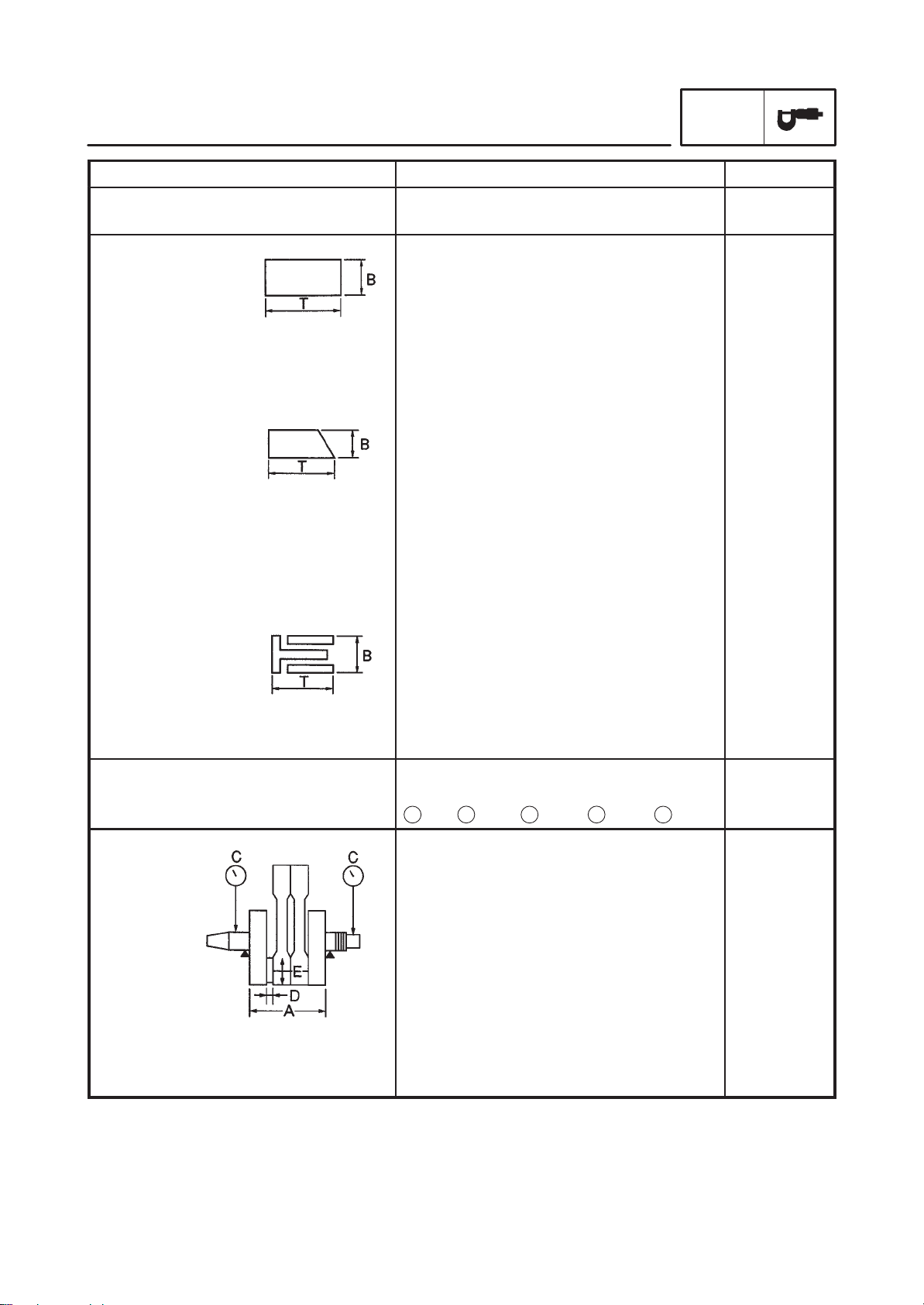
EB202001
GENERAL TORQUE
SPECIFICATIONS
This chart specifies torque for standard fasteners with standard I.S.O. pitch threads. Torque
specifications for special components or assemblies are provided for each chapter of this
manual. T o avoid warpage, tighten multi-fastener assemblies in a crisscross fashion, in progressive stages, until the specified torque is
reached. Unless otherwise specified, torque
specifications require clean, dry threads. Components should be at room temperature.
A: Distance between flats
B: Outside thread diameter
A
(nut)
B
(Bolt)
10 mm 6 mm 6 0,6
12 mm 8 mm 15 1,5
14 mm 10 mm 30 3,0
17 mm 12 mm 55 5,5
General torque
specifications
Nm
mSkg
EAS00028
CONVERSION TABLE
All specification data in this manual are listed
in SI and METRIC UNITS.
Use this table to convert METRIC unit data to
IMPERIAL unit data.
Ex.
METRIC MULTIPLIER IMP
** mm x 0.03937 = ** in
2 mm x 0.03937 = 0.08 in
CONVERSION TABLE
METRIC TO IMP
Known Multiplier Result
Torque
Weight
Distance
Volume/
Capacity
Miscellaneous
mSkg
mSkg
cmSkg
cmSkg
kg
g
km/hr
km
m
m
cm
mm
cc (cm3)
cc (cm
lt (liter)
It (liter)
kg/mm
kg/cm
Centigrade
3
)
2
7.233
86.794
0.0723
0.8679
2.205
0.03527
0.6214
0.6214
3.281
1.094
0.3937
0.03937
0.03527
0.06102
0.8799
0.2199
55.997
14.2234
9/5 (_C) + 32
ftSlb
inSlb
ftSlb
inSlb
lb
oz
mph
mi
ft
yd
in
in
oz (IMP liq.)
cuSin
qt (IMP liq.)
gal (IMP liq.)
lb/in
psi (lb/in
Fahrenheit (_F)
2
)
19 mm 14 mm 85 8,5
22 mm 16 mm 130 13,0
2-20
Page 39

LUBRICATION POINTS AND LUBRICANT TYPES
EB203000
LUBRICATION POINTS AND LUBRICANT TYPES
ENGINE
SPEC
Lubrication point
Oil seal lips
O-ring
Bearing
Connecting rod bolt/nut
Connecting rod small end and big end
Crankshaft pin
Crankshaft journal/big end
Piston surface
Piston pin
Camshaft cam lobe/journal
Rocker arm shaft
Valve stem (IN, EX)
Symbol
Valve stem end (IN, EX)
Timing chain drive gear shafts/sprokets
Oil pump rotor (inner/outer), housing
Idle gear surface
Starter idle gear
Starter idle gear shaft
Starter oneway cam
Middle drive gear
Primary driven gear
Push rod 1, 2
Transmission gear (wheel/pinion)
Shift cam
Shift fork/guide bar
Shift shaft assembly
Push rod ball
Push lever assembly
2-21
Page 40

EB203010
CHASSIS
LUBRICATION POINTS AND LUBRICANT TYPES
SPEC
Lubrication point
Steering head pipe (upper/lower), bearing
Steering head pipe, bearing cover lip
Steering head pipe, oil seal lip
Front wheel oil seal lip (right/left)
Rear wheel oil seal lip
Clutch hub fitting area
Rear brake pedal shaft
Shift pedal shaft
Sidestand bolt, sidestand sliding surface
Tube guide (throttle grip) inner surface
Brake lever pivot bolt, contact surface
Clutch lever pivot bolt, contact surface
Symbol
Rear shock absorber (lower) oil seal lip
Swingarm pivot bearing inner surface
Swingarm pivot oil seal lip
Relay arm bearing, collar and oil seal
Drive shaft spline
Drive shaft dust cover
2-22
Page 41

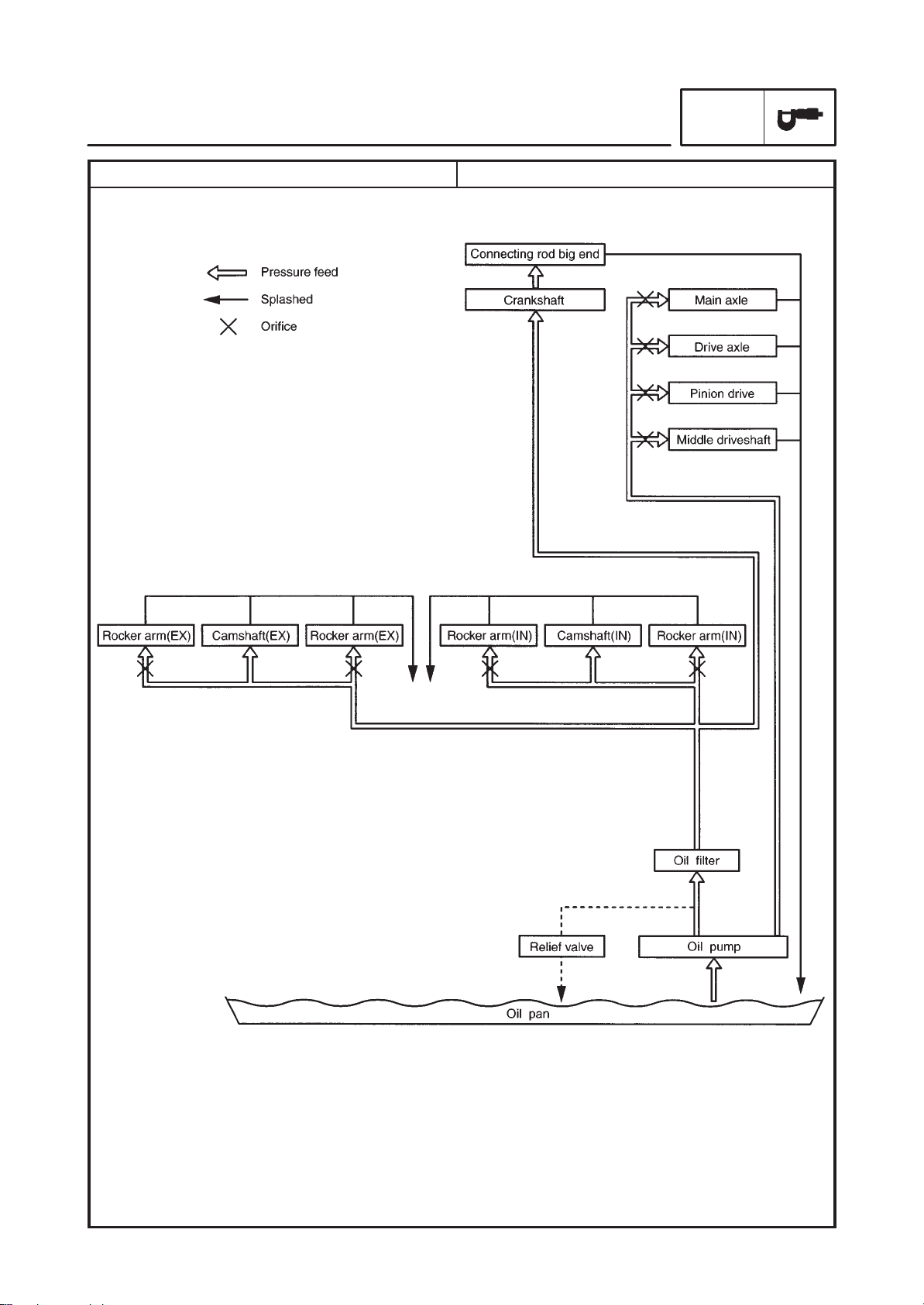
EB205000
LUBRICATION DIAGRAMS
1 Rocker arm shaft (intake)
2 Rocker arm shaft (exhaust)
3 Oil filter
4 Oil pump
5 Drive axle
6 Middle drive shaft
LUBRICATION DIAGRAMS
SPEC
2-23
Page 42

2 Releaf valve
3 Oil filter
LUBRICATION DIAGRAMS
4 Middle drive shaft1 Oil pump
SPEC
2-24
Page 43

LUBRICATION DIAGRAMS
SPEC
1 Camshaft
2 Crankshaft
3 Main axle
4 Middle drive shaft
5 Drive axle
6 Connecting rod big end
2-25
Page 44

EB206000
CABLE ROUTING
1 Clutch cable
2 Starter cable
3 Handlebar switch lead (left)
4 Handlebar switch lead (right)
5 High tension code
6 Starter cable
7 Throttle cable
8 Fuel hose (fuel cock-fuel filter)
9 Fuse box
CABLE ROUTING
10 Alarm connector
11 Fuel pump lead
12 Speed sensor lead
13 Sidestand switch lead
14 Neutral switch lead
15 Pickup coil lead
16 AC magneto lead
17 Ventilation hose
18 Sensing hose (AIS-carburetor
joint)
SPEC
19 Fuel hose (carburetor-fuel pump)
20 Brake hose
21 Heat protector
22 Fuel breather hose (fuel tank-
roll over valve) (for California)
23 Speedometer lead
24 Wireharness
25 Purge hose (carburetor-solenoid
valve) (for California)
2-26
Page 45

CABLE ROUTING
SPEC
27
26 Purge hose (carburetor-solenoid
valve) (for California)
A Fasten the handlebar switch
leads (left and right) to the
handlebar with plastic locking
tie.
B Position the throttle cable and
starter cable as shown, and
clamp them with holder.
C Clamp the wire harness with
the hook of frame side.
D When installing the pipe of
throttle cables, press it inside.
E Connect the sensing hose
(carburetor joint-AIS side) with
a nozzle.
F Push the wire harness inside
of the tool box plate.
G Route the sidestand lead
inside of engine cover.
H Position the all connectors
inside of the connector cover.
I Route the clutch cable through
the cable guide.
2-27
Page 46

CABLE ROUTING
SPEC
J Fasten the handlebar switch
leads (left and right) under the
handle crown with a plastic
band.
Set the band at four notches,
and install it no slacking.
K Route the each hoses through
the frame guide and do not
pinch it.
L When installing the fitting plate,
do not pinch the each hoses
and wire harness.
M Fasten the AC magneto lead
and sidestand switch lead with a
plastic locking tie.
N Fasten the alarm lead with a
plastic band on the lid.
2-28
Page 47

E
1 Battery
2 Battery positive (+) lead
3 Starter motor positive (+) lead
4 Speedometer lead
5 Fuel hose (carburetor-fuel pump)
6 High tension code
7 Main switch lead
8 Throttle cable
9 Brake hose
10 Handlebar switch lead (right)
11 Headlight lead
CABLE ROUTING
12 Ignition coil
13 Master cylinder reservoir hose
14 Breather hose
15 Air filter drain hose
16 Battery negative (–) lead
17 Rear brake switch lead
18 Rear brake hose
19 Carburetor heater connector
20 Rectifier/regulator
21 Main switch lead
22 Flasher relay
SPEC
23 Handlebar switch lead (left)
24 Throttle position sensor lead
25 Carburetor heater lead
26 Thermo switch lead
27 Starting circuit cutoff relay
28 Down tube
29 High tension code
30 Purge hose (carburetor-
solenoid valve) (for California)
31 Carburetor heater lead
32 Oil level switch lead
2-29
Page 48

E
A Clamp the battery positive (+)
lead to the battery with battery
band.
B Connect the battery negative
(–) lead connector and push it
into the space between battery
box and battery.
C Route the rectifier/regulator
lead, wire harness and starter
motor positive (+) lead through
the outside of frame bracket
and fasten them to the frame
with a plastic locking tie.
CABLE ROUTING
D Connect the purge hose
(carburetor side-solenoid valve
side) with joint. (for California)
E Route the front turn signal light
lead and headlight lead through
the rear of headlight body hole.
F Connect the ignition coil lead at
red tape to the right side.
G Fasten the rear brake switch
lead to the brake switch bracket
with a plastic locking tie.
SPEC
H Fasten the rear brake switch
lead and master cylinder
reservoir hose to the down
tube with a plastic locking tie.
I Fasten the wire harness,
starter motor positive (+) lead
and battery negative (–) lead to
the frame with a plastic locking tie.
J Route the rectifier/regulator
lead and carburetor heater lead
through inside of battery box
hole to outside it and connect
them.
2-30
Page 49

E
K To rear brake caliper
L Clamp the handlebar switch
lead (right) and main switch
lead to the frame with a holder.
M Arrange the throttle position
sensor connector, carburetor
heater connector and thermo
switch connector between the
starting circuit cutoff relay and
high tension code.
N Fasten the rear brake switch
to the down tube with a plastic
locking tie.
CABLE ROUTING
SPEC
2-31
Page 50

E
1 Brake hose
2 Throttle cable
3 Master cylinder reservoir hose
4 High tension code
5 Purge hose (carburetor-solenoid
valve) (for California)
6 Rear brake switch lead
7 Brake hose
8 Sensing hose (AIS-carburetor
joint)
9 Fuel hose (carburetor-fuel
pump)
10 Battery negative (–) lead
CABLE ROUTING
11 Battery negative (–) lead
connector
12 Battery
13 Battery positive (+) lead
14 Taillight lead
15 Starter relay
16 Starter motor positive (+) lead
17 Speedometer lead connector
18 Fuel tank breather hose
(fuel tank-roll over valve) (for
California)
19 Ventilation hose
SPEC
20 Starter cable
21 Fuel hose (fuel cock-fuel filter)
22 Carburetor heater lead
23 Thermo switch lead
24 Igniter unit
25 Taillight lead
26 Throttle position sensor lead
27 Fuel filter
28 Igniter unit lead
29 Frame
30 Wire harness
A Clamp the throttle cables with
the holder.
2-32
Page 51

E
B Route the rear brake switch
lead under the master cylinder
reservoir hose.
C Position the band end of right
side bracket.
D Position the steel band end to
forward.
E Position the steel band end to
right side.
CABLE ROUTING
F Route the battery positive (+)
lead through the slit of the
battery box.
G Clamp the igniter unit lead to
the frame with a holder.
H To the rear fender.
I Route the fuel tank breather
hose under the fuel filter and
connect it (fuel tank side-roll
over valve side) with a joint.
Position the end of clip outside.
SPEC
J Fasten the wire harness with a
band on the tool box plate.
K Fasten the wire harness to the
frame with a plastic locking tie.
Position the locking tie front of
the solder.
2-33
Page 52

E
L Route wire harness outside of
the guide on the frame.
M Clamp the clutch cable and
starter cable with a holder.
Position the end of holder down
side.
N Route the throttle position
sensor lead and carburetor
heater lead left side of the
tappet cover.
O To the wire harness.
CABLE ROUTING
P Route the igniter lead through
the igniter plate hole to the wire
harness.
Q Clamp the taillight lead with
mud guard clamp.
R Clamp the taillight lead with a
holder on the mud guard.
SPEC
2-34
Page 53

E
1 Throttle cable
2 Starter cable
3 Clutch cable
4 Handlebar switch lead (left)
5 Headlight lead
6 Brake hose
A Route the handlebar switch
lead (right) rear side of the
throttle cable.
CABLE ROUTING
SPEC
2-35
Page 54

INSP
ADJ
3
Page 55

INSP
ADJ
CHAPTER 3
PERIODIC INSPECTIONS AND ADJUSTMENTS
INTRODUCTION 3-1. . . . . . . . . . . . . . . . . . . . . . . . . . . . . . . . . . . . . . . . . . . . . . .
PERIODIC MAINTENANCE/LUBRICATION INTERVALS 3-1. . . . . . . . . . .
FUEL TANK AND SEATS 3-3. . . . . . . . . . . . . . . . . . . . . . . . . . . . . . . . . . . . . . .
REMOV AL 3-4. . . . . . . . . . . . . . . . . . . . . . . . . . . . . . . . . . . . . . . . . . . . . . . . .
INST ALLA TION 3-4. . . . . . . . . . . . . . . . . . . . . . . . . . . . . . . . . . . . . . . . . . . . .
ENGINE 3-5. . . . . . . . . . . . . . . . . . . . . . . . . . . . . . . . . . . . . . . . . . . . . . . . . . . . . .
ADJUSTING THE VALVE CLEARANCE 3-5. . . . . . . . . . . . . . . . . . . . . . .
SYNCHRONIZING THE CARBURETORS 3-8. . . . . . . . . . . . . . . . . . . . . .
ADJUSTING THE ENGINE IDLING SPEED 3-10. . . . . . . . . . . . . . . . . . . .
ADJUSTING THE THROTTLE CABLE FREE PLAY 3-11. . . . . . . . . . . . .
CHECKING THE SPARK PLUGS 3-12. . . . . . . . . . . . . . . . . . . . . . . . . . . . .
CHECKING THE IGNITION TIMING 3-13. . . . . . . . . . . . . . . . . . . . . . . . . . .
MEASURING THE COMPRESSION PRESSURE 3-14. . . . . . . . . . . . . . .
CHECKING THE ENGINE OIL LEVEL 3-16. . . . . . . . . . . . . . . . . . . . . . . . .
CHANGING THE ENGINE OIL 3-17. . . . . . . . . . . . . . . . . . . . . . . . . . . . . . .
ADJUSTING THE CLUTCH CABLE FREE PLAY 3-18. . . . . . . . . . . . . . . .
CLEANING THE AIR FILTER ELEMENT 3-19. . . . . . . . . . . . . . . . . . . . . . .
CHECKING THE CARBURETOR JOINT AND INTAKE
MANIFOLD 3-20. . . . . . . . . . . . . . . . . . . . . . . . . . . . . . . . . . . . . . . . . . . . .
CHECKING THE BREATHER HOSE 3-20. . . . . . . . . . . . . . . . . . . . . . . . . .
CHECKING THE EXHAUST SYSTEM 3-21. . . . . . . . . . . . . . . . . . . . . . . . .
CHASSIS 3-22. . . . . . . . . . . . . . . . . . . . . . . . . . . . . . . . . . . . . . . . . . . . . . . . . . . . .
ADJUSTING THE FRONT BRAKE 3-22. . . . . . . . . . . . . . . . . . . . . . . . . . . .
ADJUSTING THE REAR BRAKE 3-23. . . . . . . . . . . . . . . . . . . . . . . . . . . . .
CHECKING THE BRAKE FLUID LEVEL 3-24. . . . . . . . . . . . . . . . . . . . . . .
ADJUSTING THE REAR BRAKE LIGHT SWITCH 3-25. . . . . . . . . . . . . . .
CHECKING THE BRAKE HOSES 3-25. . . . . . . . . . . . . . . . . . . . . . . . . . . . .
BLEEDING THE HYDRAULIC BRAKE SYSTEM 3-26. . . . . . . . . . . . . . . .
ADJUSTING THE SHIFT PEDAL 3-27. . . . . . . . . . . . . . . . . . . . . . . . . . . . .
CHECKING THE FINAL DRIVE OIL LEVEL 3-28. . . . . . . . . . . . . . . . . . . .
CHANGING THE FINAL DRIVE OIL 3-28. . . . . . . . . . . . . . . . . . . . . . . . . . .
CHECKING AND ADJUSTING THE STEERING HEAD 3-29. . . . . . . . . .
CHECKING THE FRONT FORK 3-31. . . . . . . . . . . . . . . . . . . . . . . . . . . . . .
ADJUSTING THE REAR SHOCK ABSORBER ASSEMBLY 3-31. . . . . .
CHECKING THE TIRES 3-32. . . . . . . . . . . . . . . . . . . . . . . . . . . . . . . . . . . . .
CHECKING AND TIGHTENING THE SPOKES 3-35. . . . . . . . . . . . . . . . .
CHECKING AND LUBRICATING THE CABLES 3-36. . . . . . . . . . . . . . . . .
LUBRICATING THE LEVERS AND PEDALS 3-36. . . . . . . . . . . . . . . . . . .
LUBRICATING THE SIDESTAND 3-36. . . . . . . . . . . . . . . . . . . . . . . . . . . . .
LUBRICATING THE REAR SUSPENSION 3-36. . . . . . . . . . . . . . . . . . . . .
Page 56

INSP
ADJ
ELECTRICAL SYSTEM 3-37. . . . . . . . . . . . . . . . . . . . . . . . . . . . . . . . . . . . . . . . .
CHECKING AND CHARGING THE BATTERY 3-37. . . . . . . . . . . . . . . . . .
CHECKING THE FUSES 3-43. . . . . . . . . . . . . . . . . . . . . . . . . . . . . . . . . . . .
REPLACING THE HEADLIGHT BULB 3-44. . . . . . . . . . . . . . . . . . . . . . . . .
ADJUSTING THE HEADLIGHT BEAM 3-45. . . . . . . . . . . . . . . . . . . . . . . . .
Page 57

INTRODUCTION/PERIODIC MAINTENANCE/
LUBRICATION INTERVALS
EB300000
INSP
ADJ
PERIODIC INSPECTIONS AND ADJUSTMENTS
INTRODUCTION
This chapter includes all information necessary to perform recommended inspections and adjustments. These preventive maintenance procedures, if followed, will ensure more reliable vehicle operation and a longer service life. The need for costly overhaul work will be greatly reduced. This information applies to vehicles already in service as well as to new vehicles that are being prepared for sale. All
service technicians should be familiar with this entire chapter.
EB301000
PERIODIC MAINTENANCE/LUBRICATION INTERVALS
EVERY
NO. ITEM CHECKS AND MAINTENANCE JOBS
1 * Fuel line (manual cock)
2 * Fuel filter
3 Spark plugs
4 * Valves (arm SOHC)
5 Air filter Clean or replace if necessary. √ √
6 Clutch
7 * Front brake (disc)
8 * Rear brake (disc)
9 * Wheels (spoke)
10 * Tires (EUR)
11 * Wheel bearings
12 * Swingarm (no nipple)
13 * Steering bearings
14 * Chassis fasteners
15 Sidestand
16 * Sidestand switch
Check fuel hoses for cracks or damage.
Replace if necessary .
Check condition.
Replace if necessary .
Check condition.
Clean, regap or replace if necessary .
Check valve clearance.
Adjust if necessary .
Check operation.
Adjust or replace cable.
Check operation, fluid level and vehicle for fluid leakage.
(See NOTE.)
Correct accordingly .
Repalce brake pads if necessary .
Check operation, fluid level and vehicle for fluid leakage.
(See NOTE.)
Correct accordingly .
Replace brake pads if necessary .
Check balance, runout, spoke tightness and for damage.
Tighten spokes and rebalance, replace if necessary.
Check tread depth and for damage.
Replace if necessary .
Check air pressure.
Correct if necessary .
Check bearing for looseness or damage.
Replace if necessary .
Check swingarm pivoting point for play .
Correct if necessary .
Lubricate with molybdenum disulfide grease every
24,000 km or 24 months (whichever comes first).
Check bearing play and steering for roughness.
Correct accordingly .
Lubricate with lithium soap base grease every 24,000
km or 24 months (whichever comes first).
Make sure that all nuts, bolts and screws are properly
tightened.
Tighten if necessary.
Check operation.
Lubricate and repair if necessary .
Check operation.
Replace if necessary .
Initial
(1,000 km)
√ √ √
√ √ √
√ √ √
√ √ √
√ √ √
√ √ √
6,000 km
or
6 months
(whichever
comes first)
√ √
√ √
√ √
√ √
√ √
√ √
√ √
√ √
12,000 km
or
12 months
(whichever
comes first)
√
3-1
Page 58

INSP
PERIODIC MAINTENANCE/LUBRICA TION INTER VALS
NO. ITEM CHECKS AND MAINTENANCE JOBS
17 * Front fork
Rear shock absorber
18 *
assembly
19 * Carburetors (multi)
20 Engine oil
Engine oil filter
21 *
element
22 Final gear oil
Check operation and for oil leakage.
Correct accordingly .
Check operation and shock absorber for oil leakage.
Replace shock absorber assembly if necessary .
Check engine idlilng speed, synchronization and start-
er operation.
Adjust if necessary .
Check oil level and vehicle for oil leakage.
Correct if necessary .
Change. (Warm engine before draining.)
Replace. √ √
Check oil level and vehicle for oil leakage.
Change oil at initial 1,000 km and thereafter every
24,000 km or 24 months (whichever comes first).
* Since these items require special tools, data and technical skills, they should be serviced by a Yamaha dealer.
Initial
(1,000 km)
√ √ √
√ √ √
√ √ √
ADJ
EVERY
6,000 km
or
6 months
(whichever
comes first)
√ √
√ √
12 months
(whichever
comes first)
12,000 km
or
NOTE:
The air filter needs more frequent service if you are riding in unusually wet or dusty areas.
Hydraulic brake system
–When disassembling the master cylinder or caliper cylinder, always replace the brake fluid. Check
the brake fluid level regularly and fill as required.
–Replace the oil seals on the inner parts of the master cylinder and caliper cylinder every two years.
–Replace the brake hoses every four years or if cracked or damaged.
3-2
Page 59

FUEL TANK AND SEATS
FUEL TANK AND SEATS
23Nm (2.3mkg)
INSP
ADJ
7 Nm (0.7mkg)
7 Nm (0.7mkg)
Order Job name/Part name Q’ty Remarks
Fuel tank and seats removal
Passenger seat
1
Seat bracket
2
Rider’s seat
3
Fuel hose
4
Ignitor plate
5
Mud guard
6
Meter lead couper
7
Fuel tank assembly
8
3-3
Remove the parts in the order below.
1
1
1
NOTE:
1
Set the fuel cock to “OFF” before dis-
connecting the fuel hose.
1
1
1
1
For installation, reverse the removal
procedure.
Page 60

FUEL TANK AND SEATS
REMOVAL
1. Remove:
Ignitor plate
NOTE:
To remove the quick fastener, push its center in
with a screwdriver, then pull the fastener out.
INSP
ADJ
INSTALLATION
1. Install:
Ignitor plate
NOTE:
T o install the quick fastener, push its pin so that it
protrudes from the fastener head, then insert
the fastener into the cowling and push the pin
in with a screwdriver. Make sure that the pin is
flush with the fastener’s head.
a
3-4
Page 61

ADJUSTING THE VALVE CLEARANCE
EAS00047
ENGINE
ADJUSTING THE VALVE CLEARANCE
The following procedure applies to all of the
valves.
NOTE:
Valve clearance adjustment should be made
on a cold engine, at room temperature.
When the valve clearance is to be measured or
adjusted, the piston must be at top dead center
(TDC) on the compression stroke.
1. Remove:
rider’s seat
fuel tank
Refer to “FUEL TANK AND SEATS”.
2. Disconnect:
spark plug caps
3. Remove:
spark plugs
INSP
ADJ
4. Remove:
air intake box
5. Remove:
cylinder head cover (rear cylinder)
cylinder head cover (front cylinder)
1
1
3-5
Page 62

ADJUSTING THE VALVE CLEARANCE
6. Remove:
tappet covers
7. Remove:
camshaft sprocket cover (rear cylinder)
camshaft sprocket cover (front cylinder)
1
INSP
ADJ
1
8. Remove:
timing plug
straight plug
9. Measure:
valve clearance
Out of specification Adjust.
1
2
Valve clearance (cold):
Intake valve:
0.07 0.12 mm
Exhaust valve:
0.12 0.17 mm
3-6
Page 63

A B
ADJUSTING THE VALVE CLEARANCE
a. Turn the crankshaft counterclockwise.
b. When the piston is at TDC on the compres-
sion stroke, align either the camshaft sprocket plate hole
on the cylinder head. When the camshaft
sprocket plate hole or camshaft sprocket
punch mark is aligned with the stationary
pointer, the piston is at top dead center
(TDC).
c. Align the TDC mark
with the stationary pointer
case.
Rear cylinder (“TI” mark)
A
Front cylinder (“I” mark)
B
a
with the stationary pointer
INSP
ADJ
c
on the generator rotor
d
on the crank-
b
d. Measure the valve clearance with a thick-
1
ness gauge
e. Turn the crankshaft crockwise 290_, and
then measure the front cylinder.
10. Adjust
S valve clearance
a. Loosen the locknut
b. Insert a thickness gauge between the end of
the adjusting screw and the valve tip.
c. Turn the adjusting screw
b
until the specified valve clearance is ob-
tained.
Direction
Direction
.
1
.
2
in direction a or
a
b
Valve clearance is
decreased.
Valve clearance is
increased.
d. Hold the adjusting screw to prevent it from
moving and tighten the locknut to specification.
3-7
Page 64

ADJUSTING THE VALVE CLEARANCE/
SYNCHRONIZING THE CARBURETORS
Locknut:
27 Nm (2.7 mkg)
e. Measure the valve clearance again.
f. If the valve clearance is still out of specifica-
tion, repeat all of the valve clearance adjustment steps until the specified clearance is
obtained.
11. Install:
all removed parts
NOTE:
Install all removed parts in the reverse order of
their disassembly. Note the following points.
camshaft sprocket covers
tappet covers
spark plugs
EAS00051
SYNCHRONIZING THE CARBURETORS
INSP
ADJ
10 Nm (1.0 mkg)
10 Nm (1.0 mkg)
20 Nm (2.0 mkg)
NOTE:
Prior to synchronizing the carburetors, the valve
clearance and the engine idling speed should
be properly adjusted and the ignition timing
should be checked.
1. Stand the motorcycle on a level surface.
NOTE:
Place the motorcycle on a suitable stand.
2. Remove:
rider’s seat
fuel tank
Refer to “FUEL TANK AND SEATS”.
3. Remove:
air duct
4. Remove:
vacuum plugs
1
1
3-8
Page 65

SYNCHRONIZING THE CARBURETORS
5. Install:
vacuum gauge
engine tachometer
(to the spark plug lead of cyl. #2)
Vacuum gauge:
90890-03094
Engine tachometer:
90890-03113
6. Start the engine and let it warm up for several
minutes.
7. Check:
engine idling speed
Out of specification Adjust.
Refer to “ADJUSTING THE ENGINE IDLING
SPEED”.
Engine idling speed:
950 1,050 r/min
1
INSP
ADJ
2
8. Adjust:
Carburetor synchronization
a. Synchronize carburetor #1 to carburetor #2
by turning the synchronizing screw
ther direction until both gauges read the
same.
b. Rev the engine two or three times, each time
for less than a second, and check the synchronization again.
Vacuum pressure at idle speed:
34.7 37.3 kPa (260 280 mmHg)
NOTE:
The difference between the two carburetors
should not exceed 1.33 kPa (10 mmHg).
9. Check:
engine idling speed
Out of specification Adjust.
10. Stop the engine and remove the measuring
equipment.
1 1. Adjust:
throttle cable free play
Refer to “ADJUSTING THE THROTTLE
CABLE FREE PLAY”.
1
in ei-
3-9
Page 66

SYNCHRONIZING THE CARBURETORS/
ADJUSTING THE ENGINE IDLING SPEED
Throttle cable free play (at the
flange of the throttle grip)
4 6 mm
12. Install:
vacuum plugs
air duct
fuel tank
seat
EAS00054
ADJUSTING THE ENGINE IDLING SPEED
NOTE:
Prior to adjusting the engine idling speed, the
carburetor synchronization should be adjusted
properly, the air filter should be clean, and the
engine should have adequate compression.
1. Start the engine and let it warm up for several
minutes.
2. Remove:
cylinder head cover
3. Install:
engine tachometer
(to the spark plug lead of cyl. #1)
INSP
ADJ
1
Engine tachometer:
90890-03113
4. Check:
engine idling speed
Out of specification Adjust.
Engine idling speed:
950 1,050 r/min
5. Adjust:
engine idling speed
a. Turn the pilot screw
seated.
b. Turn the pilot screw out the specified number
of turns.
Pilot screw
3 turns out
c. Turn the throttle stop screw
or b until the specified engine idling speed is
obtained.
1
in until it is lightly
2
in direction
a
3-10
Direction
Direction
a
b
Engine idling speed is
increased.
Engine idling speed is
decreased.
Page 67

ADJUSTING THE ENGINE IDLING SPEED/
ADJUSTING THE THROTTLE CABLE FREE PLAY
6. Adjust:
throttle cable free play
Refer to “ADJUSTING THE THROTTLE
CABLE FREE PLAY”.
Throttle cable free play (at the
flange of the throttle grip)
4 6 mm
EAS00058
ADJUSTING THE THROTTLE CABLE FREE
PLAY
NOTE:
Prior to adjusting the throttle cable free play , the
engine idling speed should be adjusted.
1. Check:
throttle cable free play
Out of specification Adjust.
INSP
ADJ
a
Throttle cable free play (at the
flange of the throttle grip)
4 6 mm
2. Remove:
rider’s seat
fuel tank
Refer to “FUEL TANK AND SEATS”.
3. Adjust:
throttle cable free play
NOTE:
When the motorcycle is accelerating, the accelerator cable
Carburetor side
a. Loosen the locknut 2 on the accelerator cable.
b. Turn the adjusting nut
until the specified throttle cable free play is
obtained.
Direction
1
is pulled.
a
3
in direction a or
Throttle cable free play
is decreased.
b
Direction
c. Tighten the locknuts.
NOTE:
If the specified throttle cable free play cannot be
obtained on the carburetor side of the cable, use
the adjusting nut on the handlebar side.
3-11
b
Throttle cable free play
is increased.
Page 68

ADJUSTING THE THROTTLE CABLE FREE PLAY/
CHECKING THE SPARK PLUGS
Handlebar side
a. Loosen the locknut
b. Turn the adjusting nut
until the specified throttle cable free play is
obtained.
INSP
ADJ
1
.
2
in direction a or
b
Direction
Direction
c. Tighten the locknut.
a
b
Throttle cable free play is
increased.
Throttle cable free play is
decreased.
WARNING
After adjusting the throttle cable free play,
turn the handlebar to the right and to the left
to ensure that this does not cause the engine idling speed to change.
EAS00059
CHECKING THE SPARK PLUGS
The following procedure applies to all of the
spark plugs.
1. Remove:
cylinder head covers
2. Disconnect:
spark plug cap
3. Remove:
spark plug
1
CAUTION:
Before removing the spark plugs, blow away
any dirt accumulated in the spark plug wells
with compressed air to prevent it from falling into the cylinders.
4. Check:
spark plug type
Incorrect Change.
Spark plug type (manufacturer)
BPR7ES (NGK)
W22EPR-U (DENSO)
5. Check:
electrode
Damage/wear Replace the spark plug.
insulator
Abnormal color Replace the spark plug.
Normal color is a medium-to-light tan color.
6. Clean:
spark plug
(with a spark plug cleaner or wire brush)
1
2
3-12
Page 69

CHECKING THE SPARK PLUGS/
CHECKING THE IGNITION TIMING
7. Measure:
spark plug gap
(with a wire gauge)
Out of specification Regap.
Spark plug gap
0.7 0.8 mm
8. Install:
spark plug
NOTE:
Before installing the spark plug, clean the spark
plug and gasket surface.
9. Connect:
spark plug cap
EAS00064
CHECKING THE IGNITION TIMING
a
20 Nm (2.0 mkg)
INSP
ADJ
NOTE:
Prior to checking the ignition timing, check the
wiring connections of the entire ignition system.
Make sure that all connections are tight and free
of corrosion.
1. Remove:
timing plug
1
3-13
2. Install:
timing light
engine tachometer
(to the spark plug lead of cyl. #1)
1
2
Timing light:
90890-03141
Engine tachometer:
90890-03113
Page 70

CHECKING THE IGNITION TIMING/
MEASURING THE COMPRESSION PRESSURE
3. Check:
ignition timing
a. Start the engine, warm it up for several min-
utes, and then let it run at the specified engine idling speed.
Engine idling speed:
950 1,050 r/min
INSP
ADJ
b. Check that the stationary pointer
b
the firing range
Incorrect firing range Check the ignition
system.
NOTE:
The ignition timing is not adjustable.
4. Install:
timing plug
EAS00065
MEASURING THE COMPRESSION PRESSURE
The following procedure applies to all of the cylinders.
1
on the generator rotor.
a
is within
NOTE:
Insufficient compression pressure will result in a
loss of performance.
1. Check:
valve clearance
Out of specification Adjust.
Refer to “ADJUSTING THE V ALVE CLEARANCE”.
2. Start the engine, warm it up for several min-
utes, and then turn it off.
3. Disconnect:
spark plug cap
4. Remove:
spark plug
3-14
Page 71

MEASURING THE COMPRESSION PRESSURE
CAUTION:
Before removing the spark plugs, use compressed air to blow away any dirt accumulated in the spark plug wells to prevent it
from falling into the cylinders.
5. Install:
compression gauge
Compression gauge set:
90890-03081
6. Measure:
compression pressure
Above the maximum pressure Inspect the
cylinder head, valve surfaces, and piston
crown for carbon deposits.
Below the minimum pressure Squirt a few
drops of oil into the affected cylinder and
measure again.
Refer to the following table.
INSP
ADJ
1
Compression pressure
(with oil applied in the cylinder)
Reading Diagnosis
Higher than
without oil
Same as
without oil
Compression pressure (at sea
level)
a. Turn the main switch to “ON”.
b. With the throttle wide open, crank the engine
until the reading on the compression gauge
stabilized.
Piston wear or damage
Repair.
Piston ring(-s), valves, cylinder head gasket or piston
possibly defective Repair.
Standard:
1,000 kPa (10 kg/cm
Minimum:
900 kPa (9 kg/cm
Maximum:
1,100 kPa (11 kg/cm
2
2
, 9 bar)
2
, 10 bar)
, 11 bar)
WARNING
To prevent sparking, ground all spark plug
leads before cranking the engine.
NOTE:
The difference in compression pressure between cylinders should not exceed 100 kPa (1
kg/cm
3-15
2
, 1 bar).
Page 72

MEASURING THE COMPRESSION PRESSURE/
CHECKING THE ENGINE OIL LEVEL
7. Install:
spark plug
8. Connect:
spark plug cap
EAS00069
CHECKING THE ENGINE OIL LEVEL
1. Stand the motorcycle on a level surface.
NOTE:
Place the motorcycle on a suitable stand.
Make sure that the motorcycle is upright.
2. Let the engine idle for a few minutes.
INSP
ADJ
20 Nm (2.0 mkg)
3. Check:
engine oil level
The engine oil level should be between the
minimum level marks
b
marks
Below the minimum level mark Add the
recommended engine oil to the proper level.
.
Recommended engine oil
Refer to the chart for the
engine oil grade which is best
suited for certain atmospheric
temperatures.
API standard
SE or higher grade
ACEA standard
G4 or G5
a
and maximum level
CAUTION:
Engine oil also lubricates the clutch and
the wrong oil types or additives could
cause clutch slippage. Therefore, do not
add any chemical additives or use engine
oils with a grade of CD
not use oils labeled “ENERGY CONSERVING II”
Do not allow foreign materials to enter the
crankcase.
b
or higher.
a
or higher and do
3-16
Page 73

CHECKING THE ENGINE OIL LEVEL/
CHANGING THE ENGINE OIL
4. Start the engine, warm it up for several min-
utes, and then turn it off.
5. Check the engine oil level again.
NOTE:
Before checking the engine oil level, wait a few
minutes until the oil has settled.
EAS00075
CHANGING THE ENGINE OIL
1. Start the engine, warm it up for several min-
utes, and then turn it off.
2. Place a container under the engine oil drain
bolt.
3. Remove:
engine oil filler cap
o-ring
engine oil drain bolt
gasket
4. Drain:
engine oil
(completely from the crankcase)
5. If the oil filter element is also to be replaced,
perform the following procedure.
INSP
ADJ
1
2
WARNING
Oil filter element replacement should be
made cold exhaust pipe and muffler, at room
temperature.
1
a. Remove the muffler
2
tank
(front cylinder)
b. Remove the oil filter element cover plate
element cover
c. Check the O-ring
cracked or damaged.
d. Install the new oil filter element and the ele-
ment cover.
e. Install the exhaust pipe (front cylinder), ele-
ment cover plate, rear brake reservoir tank
and muffler.
Refer to “ENGINE” in chapter 4.
6. Check:
engine oil drain bolt gasket
Damage Replace.
7. Install:
gasket
engine oil drain bolt
8. Fill:
crankcase
(with the specified amount of the recommended engine oil)
, element cover 3 and exhaust pipe
4
6
Oil filter element cover bolt
10 Nm (1.0 mkg)
, rear brake reservoir
.
and oil filter element 7.
8
and replace it if it is
43 Nm (4.3 mkg)
5
,
3-17
Page 74

CHANGING THE ENGINE OIL/
ADJUSTING THE CLUTCH CABLE FREE PLAY
Quantity
Total amount
3.6 L
Without oil filter element
replacement
3.0 L
With oil filter element
replacement
3.1 L
9. Install:
o-ring
engine oil filter cap
10. Start the engine, warm it up for several minutes, and then turn it off.
11. Check:
engine
(for engine oil leaks)
12. Check:
engine oil level
Refer to “CHECKING THE ENGINE OIL
LEVEL”.
INSP
ADJ
EAS00078
ADJUSTING THE CLUTCH CABLE FREE
PLAY
1. Check:
clutch cable free play
Out of specification Adjust.
Clutch cable free play (at the end
of the clutch lever)
5 10 mm
2. Adjust:
clutch cable free play
Handlebar side
a. Loosen the locknut
b. Turn the adjusting screw
c
until the specified clutch cable free play is
obtained.
Direction
Direction
b
c
Clutch cable free play is
increased.
Clutch cable free play is
decreased.
a
1
.
2
in direction b or
c. Tighten the locknut.
NOTE:
If the specified clutch cable free play cannot be
obtained as described above, perform the mechanism adjustment procedure described below.
3. Remove:
left side cover
clutch adjusting cover
3-18
1
2
Page 75

ADJUSTING THE CLUTCH CABLE FREE PLAY/
CLEANING THE AIR FILTER ELEMENT
4. Adjust:
clutch mechanism
Engine side
a. Loosen the locknut
b. Turn in the adjusting screw
seated.
c. Turn the adjusting screw out 1/4 of a turn.
d. Tighten the locknut.
e. Check the clutch cable free play again and
ajust it if necessary.
EAS00086
CLEANING THE AIR FILTER ELEMENT
1. Remove:
air filter case cover
air filter element
2
1
1
INSP
.
ADJ
2
until it is lightly
3-19
2. Clean:
air filter element
Apply compressed air to the outer surface of
the air filter element.
3. Check:
air filter element
Damage Replace.
4. Install:
air filter element
air filter case cover
Page 76

CHECKING THE CARBURETOR JOINT AND INTAKE MANIFOLD/
CLEANING THE AIR FILTER ELEMENT/
CHECKING THE BREA THER HOSE
CAUTION:
Never operate the engine without the air filter
element installed. Unfiltered air will cause
rapid wear of engine parts and may damage
the engine. Operating the engine without the
air filter element will also affect the carburetor
turning, leading to poor engine performance
and possible overheating.
NOTE:
When installing the air filter element into the air
filter case cover, be sure their sealing surfaces
are aligned to prevent any air leaks.
INSP
ADJ
EAS00094
CHECKING THE CARBURETOR JOINT AND
INTAKE MANIFOLD
1. Check:
carburetor joint
1
Cracks/damage Replace.
Refer to “CARBURETOR” in chapter 6.
EAS00098
CHECKING THE BREATHER HOSE
1. Remove:
cylinder head cover
2. Check:
cylinder head breather hose
1
Cracks/damage Replace.
Loose connection Connect properly.
CAUTION:
Make sure that the cylinder head breather
hose is routed correctly.
3-20
Page 77

CHECKING THE EXHAUST SYSTEM
EAS00100
CHECKING THE EXHAUST SYSTEM
The following procedure applies to all of the exhaust pipes, mufflers and gaskets.
1. Check:
exhaust pipes
muffler
Cracks/damage Replace.
gaskets
Exhaust gas leaks Replace.
2. Check:
tightening torque
2
1
3
INSP
ADJ
Exhaust pipe nut
20 Nm (2.0 mkg)
Exhaust pipe and muffler bolt
20 Nm (2.0 mkg)
Muffler and muffler bracket bolt
25 Nm (2.5 mkg)
4
5
6
3-21
Page 78

ADJUSTING THE FRONT BRAKE
EAS00108
CHASSIS
ADJUSTING THE FRONT BRAKE
1. Check:
brake lever free play
Out of specification Adjust.
Brake lever free play (at the end
of the brake lever)
5 8 mm
2. Adjust:
brake lever free play
INSP
ADJ
a
a. Loosen the locknut
b. Turn the adjusting bolt
until the specified brake lever free play is ob-
tained.
Direction Brake lever free play is
Direction Brake lever free play is
c. Tighten the locknut.
b
c
1
.
2
in direction b or
increased.
decreased.
c
WARNING
A soft or spongy feeling in the brake lever
can indicate the presence of air in the brake
system. Before the vehicle is operated, the
air must be removed by bleeding the brake
system. Air in the brake system will considerably reduce braking performance and
could result in loss of control and possibly
an accident. Therefore, inspect and, if necessary, bleed the brake system.
CAUTION:
After adjusting the brake lever free play,
make sure that there is no brake drag.
3-22
Page 79

ADJUSTING THE REAR BRAKE
EAS00110
ADJUSTING THE REAR BRAKE
1. Check:
brake pedal position
a
(distance
to the top of the brake pedal)
Out of specification Adjust.
2. Adjust:
brake pedal position
a. Loosen the locknut
b. Turn the adjusting bolt
until the specified brake pedal position is ob-
tained.
from the top of the rider footrest
Brake pedal position (below the
top of the rider footrest)
81.8 mm
INSP
ADJ
1
.
2
in direction b or
c
Direction Brake pedal is raised.
Direction Brake pedal is lowered.
b
c
WARNING
After adjusting the brake pedal position,
2
check that the end of the adjusting bolt
d
visible through the hole
c. Tighten the locknut
Locknut
16 Nm (1.6 mkg)
.
1
to specification.
is
WARNING
A soft or spongy feeling in the brake pedal
can indicate the presence of air in the brake
system. Before the vehicle is operated, the
air must be removed by bleeding the brake
system. Air in the brake system will considerably reduce braking performance and
could result in loss of control and possibly
an accident. Therefore, inspect and, if necessary, bleed the brake system.
CAUTION:
After adjusting the brake pedal position,
make sure that there is no brake drag.
3. Adjust:
rear brake light switch
Refer to “ADJUSTING THE REAR BRAKE
LIGHT SWITCH”.
3-23
Page 80

CHECKING THE BRAKE FLUID LEVEL
EAS00115
CHECKING THE BRAKE FLUID LEVEL
1. Stand the motorcycle on a level surface.
NOTE:
Place the motorcycle on a suitable stand.
Make sure that the motorcycle is upright.
INSP
ADJ
A
B
2. Check;
brake fluid level
Below the minimum level mark
recommended brake fluid to the proper level.
Recommended brake fluid
DOT 4
Front brake
A
Rear brake
B
a
Add the
WARNING
Use only the designated brake fluid. Other
brake fluids may cause the rubber seals to
deteriorate, causing leakage and poor
brake performance.
Refill with the same type of brake fluid that
is already in the system. Mixing brake
fluids may result in a harmful chemical
reaction, leading to poor brake performance.
When refilling, be careful that water does
not enter the reservoir. Water will significantly lower the boiling point of the brake
fluid and could cause vapor lock.
CAUTION:
Brake fluid may damage painted surfaces
and plastic parts. Therefore, always clean
up any spilt brake fluid immediately.
NOTE:
In order to ensure a correct reading of the brake
fluid level, make sure that the top of the reservoir is horizontal.
3-24
Page 81

ADJUSTING THE REAR BRAKE LIGHT SWITCH/
CHECKING THE BRAKE HOSES
EAS00128
ADJUSTING THE REAR BRAKE LIGHT
SWITCH
NOTE:
The rear brake light switch is operated by movement of the brake pedal.
The rear brake light switch is properly adjusted
when the brake light comes on just before the
braking effect starts.
1. Check:
rear brake light operation timing
Incorrect Adjust.
2. Adjust:
rear brake light operation timing
INSP
ADJ
a. Hold the main body
1
of the rear brake light
switch so that it does not rotate and turn the
2
adjusting nut
in direction a or b until the
rear brake light comes on at the proper time.
Direction Brake light comes on
a
sooner.
Direction Brake light comes on
b
later.
EAS00131
CHECKING THE BRAKE HOSES
The following procedure applies to all of the
brake hoses and clamps.
1. Check:
brake hose
Cracks/damage/wear Replace.
2. Check:
brake hose clamp
Loose connection Tighten.
3. Hold the motorcycle upright and apply the
brake.
4. Check:
brake hose
Activate the brake several times.
Brake fluid leakage Replace the damaged
hose.
Refer to “FRONT AND REAR BRAKES” in
chapter 7.
3-25
Page 82

BLEEDING THE HYDRAULIC BRAKE SYSTEM
EAS00134
BLEEDING THE HYDRAULIC BRAKE SYSTEM
WARNING
Bleed the hydraulic brake system whenever:
the system was disassembled,
a brake hose was loosened or removed,
the brake fluid level is very low,
brake operation is faulty.
NOTE:
Be careful not to spill any brake fluid or allow
the brake master cylinder reservoir or brake
fluid reservoir to overflow.
When bleeding the hydraulic brake system,
make sure that there is always enough brake
fluid before applying the brake. Ignoring this
precaution could allow air to enter the hydraulic brake system, considerably lengthening the
bleeding procedure.
If bleeding is difficult, it may be necessary to let
the brake fluid settle for a few hours. Repeat
the bleeding procedure when the tiny bubbles
in the hose have disappeared.
INSP
ADJ
1. Stand the motorcycle on alevel surface.
NOTE:
Place the motorcycle on a suitable stand.
Make sure that the motorcycle is upright.
A
B
2. Bleed:
hydraulic brake system
a. Add the recommended brake fluid to the
proper level.
b. Install the diaphragm (brake master cylinder
reservoir or brake fluid reservoir).
: Rear
1
tightly to the
c. Connect a clear plastic hose
2
bleed screw
: Front
A
d. Place the other end of the hose into a con-
tainer.
e. Slowly apply the brake several times.
f. Fully squeeze the brake lever or fully de-
press the brake pedal and hold it in position.
g. Loosen the bleed screw.
This will release the tension and cause the
brake lever to contact the throttle grip or the
brake pedal to fully extend.
.
B
3-26
Page 83

BLEEDING THE HYDRAULIC BRAKE SYSTEM/
ADJUSTING THE SHIFT PEDAL
h. Tighten the bleed screw and then release the
brake lever or brake pedal.
i. Repeat steps (e) to (h) until all of the air
bubbles have disappeared from the brake
fluid in the plastic hose.
j. Tighten the bleed screw to specification.
Bleed screw
6 Nm (0.6 mkg)
k. Fill the reservoir to the proper level.
Refer to “CHECKING THE BRAKE FLUID
LEVEL”.
WARNING
After bleeding the hydraulic brake system,
check the brake operation.
INSP
ADJ
EAS00137
ADJUSTING THE SHIFT PEDAL
NOTE:
The shift pedal position is determined by the adjusting bolt length
1. Measure:
adjusting the length
Incorrect Adjust.
Adjusting bolt length
114.7 mm
2. Adjust:
adjusting bolt length
a. Loosen both locknuts
b. Turn the adjusting bolt 2 in direction b or
to obtain the correct shift pedal position.
Direction shift pedal is raised.
Direction shift pedal is lowered.
a
.
a
a
1
c
b
c
3-27
Page 84

CHECKING THE FINAL DRIVE OIL LEVEL/
CHANGING THE FINAL DRIVE OIL
EAS00144
CHECKING THE FINAL DRIVE OIL LEVEL
1. Stand the motorcycle on a level surface.
NOTE:
Place the motorcycle on a suitable stand.
Make sure that the motorcycle is upright.
2. Remove:
final drive housing oil filler bolt
3. Check:
final drive oil level
The final drive oil level should be to the bot-
tom brim
Below the bottom brim Add the recom-
mended final drive oil to the proper level.
2
of the filler hole.
Recommended final drive oil
SAE 80 hypoid gear oil graded
“GL-4”, “GL-5” or “GL-6”
or
multi-purpose SAE 80W90
hypoid gear oil
INSP
ADJ
1
4. Install:
final drive housing oil filler bolt
23 Nm (2.3 mkg)
EAS00145
CHANGING THE FINAL DRIVE OIL
1. Place a container under the final drive hous-
ing.
2. Remove:
final drive housing oil filler bolt
final drive housing oil drain bolt
1
2
Completely drain the final drive housing of its
oil.
3. Check:
final drive housing oil drain bolt gasket
Damage Replace.
4. Install:
final drive housing oil drain bolt
23 Nm (2.3 mkg)
3-28
5. Fill:
final drive housing
(with the specified amount of the recom-
mended final drive oil)
Page 85

CHANGING THE FINAL DRIVE OIL/
CHECKING AND ADJUSTING THE STEERING HEAD
Quantity
0.2 L
Refer to “CHECKING THE FINAL DRIVE OIL
LEVEL”.
EAS00146
CHECKING AND ADJUSTING THE STEERING HEAD
1. Stand the motorcycle on a level surface.
W ARNING
Securely support the motorcycle so that
there is no danger of it falling over.
INSP
ADJ
NOTE:
Place the motorcycle on a suitable stand so that
the front wheel is elevated.
2. Check:
steering head
Grasp the bottom of the front fork legs and
gently rock the front fork.
Looseness or binding Adjust the steering
head.
3. Remove:
upper bracket pinch bolt
steering stem nut
upper bracket
2
3
1
4. Adjust:
steering head
a. Remove the lock washr
2
, and the rubber washer 3.
3-29
1
, the upper ring nut
Page 86

CHECKING AND ADJUSTING THE STEERING HEAD
b. Loosen the lower ring nut 4 and then tighten
it to specification with a ring nut wrench
NOTE:
Set the torque wrench at a right angle to the ring
nut wrench.
Ring nut wrench
90890-01403
Lower ring nut (initial tightening
torque)
52 Nm (5.2 mkg)
INSP
ADJ
5
.
c. Loosen the lower ring nut
tighten it to specification.
4
completely , then
WARNING
Do not overtighten the lower ring nut.
Lower ring nut (final tightening
torque)
18 Nm (1.8 mkg)
d. Check the steering head for looseness or
binding by turning the front fork all the way in
both directions. If any binding is felt, remove
the lower bracket and inspect the upper and
lower bearings.
Refer to “STEERING HEAD AND HAN-
DLEBAR” in chapter 7.
e. Install the rubber washer
f. Install the upper ring nut
g. Finger tighten the upper ring nut
align the slots of both ring nuts. If necessary ,
hold the lower ring nut and tighten the upper
ring nut until their slots are aligned.
h. Install the lock washer
3
.
2
.
2
, then
1
.
NOTE:
Make sure that the lock washer tabs
rectly in the ring nut slots
5. Install:
upper bracket
steering stem nut
upper bracket pinch bolt
3-30
a
sit cor-
b
.
110 Nm (11.0 mkg)
20 Nm (2.0 mkg)
Page 87

CHECKING THE FRONT FORK/
ADJUSTING THE REAR SHOCK ABSORBER ASSEMBLY
EAS00149
CHECKING THE FRONT FORK
1. Stand the motorcycle on a level surface.
W ARNING
Securely support the motorcycle so that
there is no danger of it falling over.
2. Check:
inner tube
Damage/scratches Replace.
oil seal
Oil leakage Replace.
3. Hold the motorcycle upright and apply the
front brake.
4. Check:
operation
Push down hard on the handlebar several
times and check if the front fork rebounds
smoothly.
Unsmooth operation Repair.
Refer to “FRONT FORK” in chapter 7.
INSP
ADJ
EAS00159
ADJUSTING THE REAR SHOCK ABSORBER ASSEMBLY
W ARNING
Securely support the motorcycle so that
there is no danger of it falling over.
CAUTION:
Never go beyond the maximum or minimum
adjustment positions.
1. Adjust:
spring preload
3-31
Page 88

ADJUSTING THE REAR SHOCK ABSORBER ASSEMBLY/
CHECKING THE TIRES
Ring nut wrench
1HX-28135-00
a. Turn the adjusting knob
b
.
INSP
ADJ
1
in direction a or
Direction Spring preload is
Direction Spring preload is
Adjusting position
Standard: 3
Minimum: 1 (soft)
Maximum: 7 (hard)
EB304174
CHECKING THE TIRES
The following procedure applies to both of the
tires.
1. Measure:
tire pressure
Out of specification Regulate.
a
increased
(suspension is harder).
b
decreased
(suspension is softer).
WARNING
The tire pressure should only be checked
and regulated when the tire temperature
equals the ambient air temperature.
The tire pressure and the suspension must
be adjusted according to the total weight
(including cargo, rider, passenger and accessories) and the anticipated riding
speed.
Operation of an overloaded motorcycle
could cause tire damage, an accident or an
injury .
NEVER OVERLOAD THE MOTORCYCLE.
3-32
Page 89

CHECKING THE TIRES
Basic
weight: (with
oil and full
fuel tank)
274 kg
INSP
ADJ
Maximum
load*:
Cold tire
pressure:
Up to 90 kg
load*
90 kg
maximum
load*
High speed
riding
201 kg
Front Rear
200 kPa
(2.00 kgf/cm
225 kPa
(2.25 kgf/cm
225 kPa
(2.25 kgf/cm
225 kPa
2
)
(2.25 kgf/cm
250 kPa
2
(2.50 kgf/cm
)
250 kPa
2
(2,50 kgf/cm
)
2
2
2
*: total of cargo, rider, passenger and acces-
sories
WARNING
It is dangerous to ride with a worn-out tire.
When the tire tread reaches the wear limit,
replace the tire immediately.
2. Check:
tire surfaces
Damage/wear Replace the tire.
)
)
)
Minimum tire tread depth
1.6 mm
Tire tread depth
1
Side wall
2
Wear indicator
3
WARNING
Do not use a tubeless tire on a wheel de-
signed only for tube tires to avoid tire failure and personal injury from sudden deflation.
When using a tube tire, be sure to install the
correct tube.
Always replace a new tube tire and a new
tube as a set.
To avoid pinching the tube, make sure that
the wheel rim band and tube are centered in
the wheel groove.
3-33
Page 90

CHECKING THE TIRES
Patching a punctured tube is not recom-
mended. If it is absolutely necessary to do
so, use great care and replace the tube as
soon as possible with a good quality replacement.
INSP
ADJ
Tube wheel
Tube tire only T ube or tubeless tire
After extensive tests, the tires listed below
have been approved by Yamaha Motor Co.,
Ltd. for this model. Then front and rear tires
should always be by the same manufacturer and of the same design. No guarantee
concerning handling characteristics can
be given if a tire combination other than
one approved by Yamaha is used on this
motorcycle.
Front tire:
Manufacturer
BRIDGESTONE
DUNLOP 110/90-18 61S K555F
Rear tire:
110/90-18 61S EXEDRA L309
Tubeless wheel
Type Size
Manufacturer
BRIDGESTONE
DUNLOP
Type Size
170/80-15
M/C 77S
170/80-15
M/C 77S
EXEDRA
G546
K555
WARNING
New tires have a relatilvely low grip on the
road surface until they have been slightly
worn.
Therefor, approximately 100 km should be
traveled at normal speed before any highspeed riding is done.
3-34
Page 91

CHECKING THE TIRES/
CHECKING AND TIGHTENING THE SPOKES
NOTE:
For tires with a direction of rotation mark
Install the tire with the mark pointing in the
direction of wheel rotation.
2
Align the mark
point.
with the valve installation
INSP
ADJ
1
:
EAS00169
CHECKING AND TIGHTENING THE SPOKES
The following procedure applies to all of the
spokes.
1. Check:
spoke
Bends/damage Replace.
Loose Tighten.
Tap the spokes with a screwdriver.
NOTE:
A tight spoke will emit a clear, ringing tone; a
loose spoke will sound flat.
2. Tighten:
spoke
(with a spoke wrench
NOTE:
Be sure to tighten the spokes before and after
break-in.
1
3 Nm (0.3 mkg)
)
2
3-35
Page 92

LUBRICATING THE LEVERS AND PEDALS/LUBRICATING
CHECKING AND LUBRICATING THE CABLES/
THE SIDEST AND/LUBRICATING THE REAR SUSPENSION
EAS00170
CHECKING AND LUBRICATING THE
CABLES
The following procedure applies to all of the
cable sheaths and cables.
W ARNING
Damaged cable sheaths may causes the
cable to corrode and interfere with its movement. Replace damaged cable sheaths and
cables as soon as possible.
1. Check:
cable sheath
Damage Replace.
2. Check:
cable operation
Unsmooth operation Lubricate.
Recommended lubricant
Engine oil or a suitable cable
lubricant
INSP
ADJ
NOTE:
Hold the cable end upright and pour a few drops
of lubricant into the cable sheath or use a suitable lubing device.
EAS00171
LUBRICATING THE LEVERS AND PEDALS
Lubricate the pivoting point and metal-to-metal
moving parts of the levers and pedals.
Recommended lubricant
Engine oil
EAS00172
LUBRICATING THE SIDESTAND
Lubricate the pivoting point and metal-to-metal
moving parts of the sidestand.
Recommended lubricant
Engine oil
EAS00174
LUBRICATING THE REAR SUSPENSION
Lubricate the pivoting point and metal-to-metal
moving parts of the rear suspension.
3-36
Recommended lubricant
Molybdenum disulfide grease
Page 93

CHECKING AND CHARGING THE BATTERY
EB305020
ELECTRICAL SYSTEM
CHECKING AND CHARGING THE BA TTER Y
WARNING
Batteries generate explosive hydrogen gas
and contain electrolyte which is made of poisonous and highly caustic sulfuric acid.
Therefore, always follow these preventive
measures:
Wear protective eye gear when handling or
working near batteries.
Charge batteries in a well-ventilated area.
Keep batteries away from fire, sparks or
open flames (e.g., welding equipment,
lighted cigarettes).
DO NOT SMOKE when charging or han-
dling batteries.
KEEP BATTERIES AND ELECTROLYTE
OUT OF REACH OF CHILDREN.
Avoid bodily contact with electrolyte as it
can cause severe burns or permanent eye
injury.
First aid in case of bodily contact:
External
SKIN – Wash with water.
EYES – Flush with water for 15 minutes and
get immediate medical attention.
Internal
Drink large quantities of water or milk followed with milk of magnesia, beaten egg or
WARNING
vegetable oil. Get immediate medical attention.
INSP
ADJ
CAUTION:
This is a sealed battery. Never remove the
sealing caps because the balance between
cells will not be maintained and battery per-
formance will deteriorate.
Charging time, charging amperage and
charging voltage for a MF battery are differ-
ent from those of conventional batteries.
The MF battery should be charged as ex-
plained in the charging method illustra-
tions. If the battery is overcharged, the
electrolyte level will drop considerably.
Therefore, take special care when charging
the battery.
3-37
Page 94

CHECKING AND CHARGING THE BATTERY
NOTE:
Since MF batteries are sealed, it is not possible
to check the charge state of the battery by measuring the specific gravity of the electrolyte.
Therefore, the charge of the battery has to be
checked by measuring the voltage at the battery
terminals.
1. Remove:
S battery cover
1
2. Disconnect:
S battery leads
(from the battery terminals)
CAUTION:
INSP
ADJ
Volt meter
First, disconnect the negative lead
the positive lead
2
.
1
, then
3. Remove:
S battery
4. Check:
S battery charge
a. Connect a pocket tester to the battery termi-
nals.
Tester positive lead battery positive
terminal
Tester negative lead battery negative
terminal
NOTE:
S The charge state of a MF battery can be
checked by measuring its open-circuit voltage
(i.e., the voltage when the positive terminal is
disconnected).
S No charging is necessary when the open-cir-
cuit voltage equals or exceeds 12.8 V.
Relationship between open-circuit
voltage and charging time at 20_C
Open-circuit voltage
D This varies depending on the temperature, the state of
charge in battery plates and the electro lyte level.
Charging time (Hours)
b. Check the charge of the battery , as shown in
the charts and the following example.
Example
c. Open-circuit voltage = 12.0 V
d. Charging time = 6.5 hours
e. Charge of the battery = 20 30 %
5. Charge:
S battery
(refer to the appropriate charging method illustration)
3-38
Page 95

CHECKING AND CHARGING THE BATTERY
INSP
ADJ
Open-circuit voltage (V)
Condition of charge in battery (%)
Charging
18
17
16
15
14
13
12
11
Open-circuit voltage (V)
10
0102030405060
Ambient
temperature 20_C
Ambient temperature
20_C
Check the Open-circuit
voltage
Time (Minutes)
WARNING
Do not quick charge a battery.
CAUTION:
S Make sure that the battery breather hose
and battery vent are free of obstructions.
S Never remove the MF battery sealing caps.
S Do not use a high-rate battery charger.
They force a high-amperage current into
the battery quickly and can cause battery
overheating and battery plate damage.
S If it is impossible to regulate the charging
current on the battery charger, be careful
not to overcharge the battery.
S When charging a battery, be sure to remove
it from the motorcycle. (If charging has to
be done with the battery mounted on the
motorcycle, disconnect the negative lead
from the battery terminal.)
S To reduce the chance of sparks, do not
plug in the battery charger until the battery
charger leads are connected to the battery .
S Before removing the battery charger lead
clips from the battery terminals, be sure to
turn off the battery charger.
S Make sure that the battery charger lead
clips are in full contact with the battery ter-
minal and that they are not shorted. A cor-
roded battery charger lead clip may gener-
ate heat in the contact area and a weak clip
spring may cause sparks.
S If the battery becomes hot to the touch at
any time during the charging process, dis-
connect the battery charger and let the bat-
tery cool before reconnecting it. Hot batter-
ies can explode!
S As shown in the following illustration, the
open-circuit voltage of a MF battery stabi-
lizes about 30 minutes after charging has
been completed. Therefore, wait 30 min-
utes after charging is completed before
measuring the open-circuit voltage.
3-39
Page 96

CHECKING AND CHARGING THE BATTERY
Charging method using a variable-current (voltage) type charger
INSP
ADJ
Charger
AMP meter
Measure the open-circuit
voltage prior to charging.
Connect a charger and
AMP meter to the battery
and start charging.
Make sure the current is
YES NO
higher than the standard
charging current written on
the battery.
Adjust the voltage so that current is at standard charging
level.
YES
NOTE:
Voltage should be measured 30 minutes after the machine is stopped.
NOTE:
Set the charging voltage at 16 17 V.
(If the setting is lower, charging will be
insufficient. If too high, the battery will
be over-charged.)
By turning the charging voltage adjust dial, set the charging voltage at 20 25 V.
Monitor the amperage for 3
5 minutes to check if the standard charging current is
reached.
Set the timer according to the
charging time suitable for the
open-circuit voltage.
Refer to “Battery condition
checking steps.”
In case that charging requires more than 5 hours, it is advisable to
check the charging current after a lapse of 5 hours. If there is any
charge in the amperage, readjust the voltage to obtain the standard
charging current.
Measure the battery open-circuit voltage after having left the battery
unused for more than 30 minutes.
12.8 V or more --- Charging is complete.
12.7 V or less --- Recharging is required.
Under 12.0 V --- Replace the battery.
NO
If the current does
not exceed standard charging current after 5 minutes, replace the
battery.
3-40
Page 97

CHECKING AND CHARGING THE BATTERY
Charging method using a constant-voltage type charger
INSP
ADJ
Measure the open-circuit
voltage prior to charging.
Connect a charger and
AMP meter to the battery
and start charging.
Make sure the current is
YES NO
higher than the standard
charging current written on
the battery.
Charge the battery until the battery’s
charging voltage is 15 V.
NOTE:
Set the charging time at 20 hours (maximum).
NOTE:
Voltage should be measured 30 minutes after the machine is stopped.
This type of battery charger cannot
charge the MF battery. A variable voltage charger is recommended.
Measure the battery open-circuit
voltage after having left the battery
unused for more than 30 minutes.
12.8 V or more --- Charging is complete.
12.7 V or less --- Recharging is re-
V olt meter
quired.
Under 12.0 V --- Replace the battery .
Charging method using a constant-current type charger
This type of battery charger cannot charge the MF battery.
Charger
AMP meter
3-41
Page 98

CHECKING AND CHARGING THE BATTERY
6. Check:
battery breather hose and battery vent
Obstruction Clean.
Damage Replace.
7. Install:
battery
CAUTION:
When inspecting the battery, make sure
that the battery breather hose is properly
attached and routed correctly . If the battery
breather hose is positioned so as to allow
electrolyte or hydrogen gas from the bat-
tery to contact the frame, the motorcycle
and its finish may be damaged.
Make sure that the battery breather hose is
properly routed away from the drive chain
and from below the swingarm.
INSP
ADJ
8. Connect:
battery leads
(to the battery terminals)
CAUTION:
First, connect the positive lead
2
negative lead
9. Check:
battery terminals
Dirt Clean with a wire brush.
Loose connection Connect properly.
10. Lubricate:
battery terminals
Recommended lubricant
11. Install:
battery cover
.
Dielectric grease
1
, then the
3-42
Page 99

CHECKING THE FUSES
EAS00181
CHECKING THE FUSES
The following procedure applies to all of the
fuses.
CAUTION:
T o avoid a short circuit, always turn the main
switch to “OFF” when checking or replacing
a fuse.
1. Remove:
rider’s seat
ignitor plate
Refer to “FUEL TANK AND SEATS”.
tool box cover
2. Check:
fuse
a. Connect the pocket tester to the fuse and
check it for continuity.
NOTE:
Set the pocket tester selector to “Ω 1”.
1
INSP
ADJ
Pocket tester
90890-03112
b. If the pocket tester indicates “∞”, replace the
fuse.
3. Replace:
blown fuse
a. Turn off the ignition.
b. Install a new fuse of the correct amperage
rating.
c. Turn on the switches to verify if the electrical
circuit is operational.
d. If the fuse immediately blows again, check
the electrical circuit.
Fuses
Main 30A 1
Headlight 15A 1
Carburetor
heater
Amperage rating Quantity
15A 1
3-43
Signals 10A 1
Ignition 10A 1
Back up 5A 1
Reserve 30A 1
Reserve 15A 1
Reserve 10A 1
Reserve 5A 1
Page 100

CHECKING THE FUSES/
REPLACING THE HEADLIGHT BULB
W ARNING
Never use a fuse with an amperage rating
other than that specified. Improvising or using a fuse with the wrong amperage rating
may cause extensive damage to the electrical system, cause the lighting and ignition
systems to malfunction and could possibly
cause a fire.
4. Install:
tool box cover
ignitor plate
rider’s seat
INSP
ADJ
EAS00182
REPLACING THE HEADLIGHT BULB
1. Disconnect:
connectors
2. Remove
headlight bulb cover
3. Remove:
headlight bulb holder
4. Remove:
headlight bulb
1
2
1
2
W ARNING
Since the headlight bulb gets extremely hot,
keep flammable products and your hands
away from the bulb until it has cooled down.
5. Install:
headlight bulb (New)
Secure the new headlight bulb with the headlight bulb holder.
3-44
 Loading...