


Yamaha XT660RW (2007), XT660R (2007), XT660XW (2007), XT660X (2007) Supplementary Service Manual

2007
XT660R(W)
XT660X(W)
SUPPLEMENTARY
SERVICE MANUAL
5VK-F8197-E2
Manuals by Motomatrix / www.motomatrix.co.uk / The Solution For Lost Motorcycle Coded Keys
email: info@motomatrix.co.uk
FOREWORD
This Supplementary Service Manual has been prepared to introduce new service and data for the
XT660R(W)/XT660X(W) 2007. For complete service information procedures it is necessary to use
this Supplementary Service Manual together with the following manual.
XT660R(S)/XT660X(S) 2004 SERVICE MANUAL: 5VK1-AE1
XT660R(W)/XT660X(W) 2007
SUPPLEMENTARY
SERVICE MANUAL
©2006 by MBK Industrie
First edition, July 2006
All rights reserved.
Any reproduction or unauthorized use
without the written permission of
MBK Industrie
is expressly prohibited.
Manuals by Motomatrix / www.motomatrix.co.uk / The Solution For Lost Motorcycle Coded Keys
email: info@motomatrix.co.uk
EAS00002
NOTICE
This manual was produced by MBK Industrie primarily for use by Yamaha dealers and their qualified mechanics. It is not possible to include all the knowledge of a mechanic in one manual. Therefore, anyone who uses this book to perform maintenance and repairs on Yamaha vehicles should
have a basic understanding of mechanics and the techniques to repair these types of vehicles.
Repair and maintenance work attempted by anyone without this knowledge is likely to render the
vehicle unsafe and unfit for use.
Yamaha is continually striving to improve all its models. Modifications and significant changes in
specifications or procedures will be forwarded to all authorized Yamaha dealers and will appear in
future editions of this manual where applicable.
NOTE:
_
Designs and specifications are subject to change without notice.
EAS00004
IMPORTANT MANUAL INFORMATION
Particularly important information is distinguished in this manual by the following.
The Safety Alert Symbol means ATTENTION! BECOME ALERT! YOUR
SAFETY IS INVOLVED!
Failure to follow WARNING instructions could result in severe injury or death
to the motorcycle operator, a bystander or a person checking or repairing
the motorcycle.
A CAUTION indicates special precautions that must be taken to avoid damage to the motorcycle.
A NOTE provides key information to make procedures easier or clearer.
WARNING
CAUTION:
NOTE:
Manuals by Motomatrix / www.motomatrix.co.uk / The Solution For Lost Motorcycle Coded Keys
email: info@motomatrix.co.uk
EAS00007
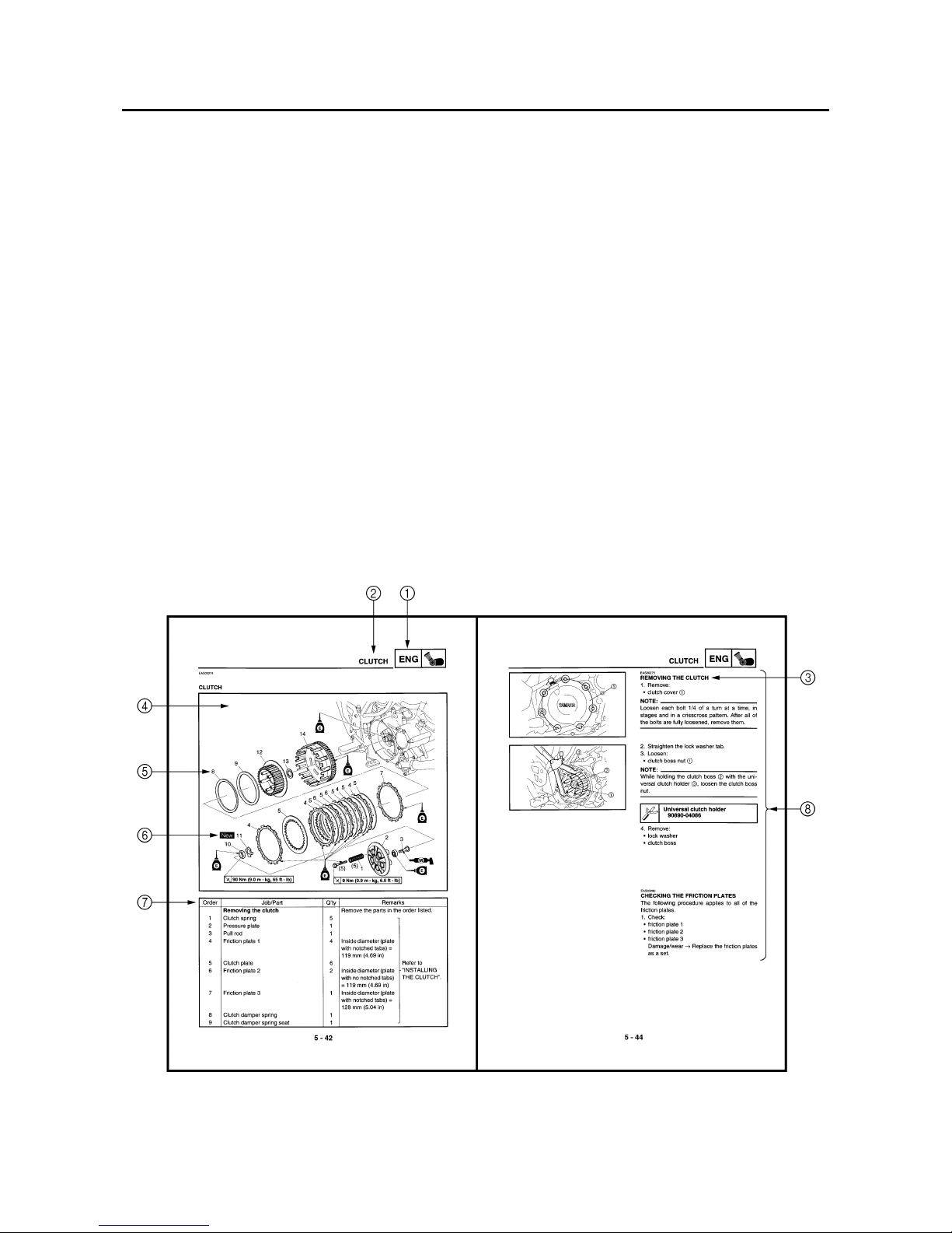
HOW TO USE THIS MANUAL
This manual is intended as a handy, easy-to-read reference book for the mechanic. Comprehensive
explanations of all installation, removal, disassembly, assembly, repair and check procedures are
laid out with the individual steps in sequential order.
1
The manual is divided into chapters. An abbreviation and symbol in the upper right corner of
each page indicate the current chapter.
Refer to “SYMBOLS”.
2
Each chapter is divided into sections. The current section title is shown at the top of each page,
except in Chapter 3 (“PERIODIC CHECKS AND ADJUSTMENTS”), where the sub-section
title(s) appears.
3
Sub-section titles appear in smaller print than the section title.
4
To help identify parts and clarify procedure steps, there are exploded diagrams at the start of
each removal and disassembly section.
5
Numbers are given in the order of the jobs in the exploded diagram. A circled number indicates a
disassembly step.
6
Symbols indicate parts to be lubricated or replaced.
Refer to “SYMBOLS”.
7
A job instruction chart accompanies the exploded diagram, providing the order of jobs, names of
parts, notes in jobs, etc.
8
Jobs requiring more information (such as special tools and technical data) are described sequentially.
Manuals by Motomatrix / www.motomatrix.co.uk / The Solution For Lost Motorcycle Coded Keys
email: info@motomatrix.co.uk
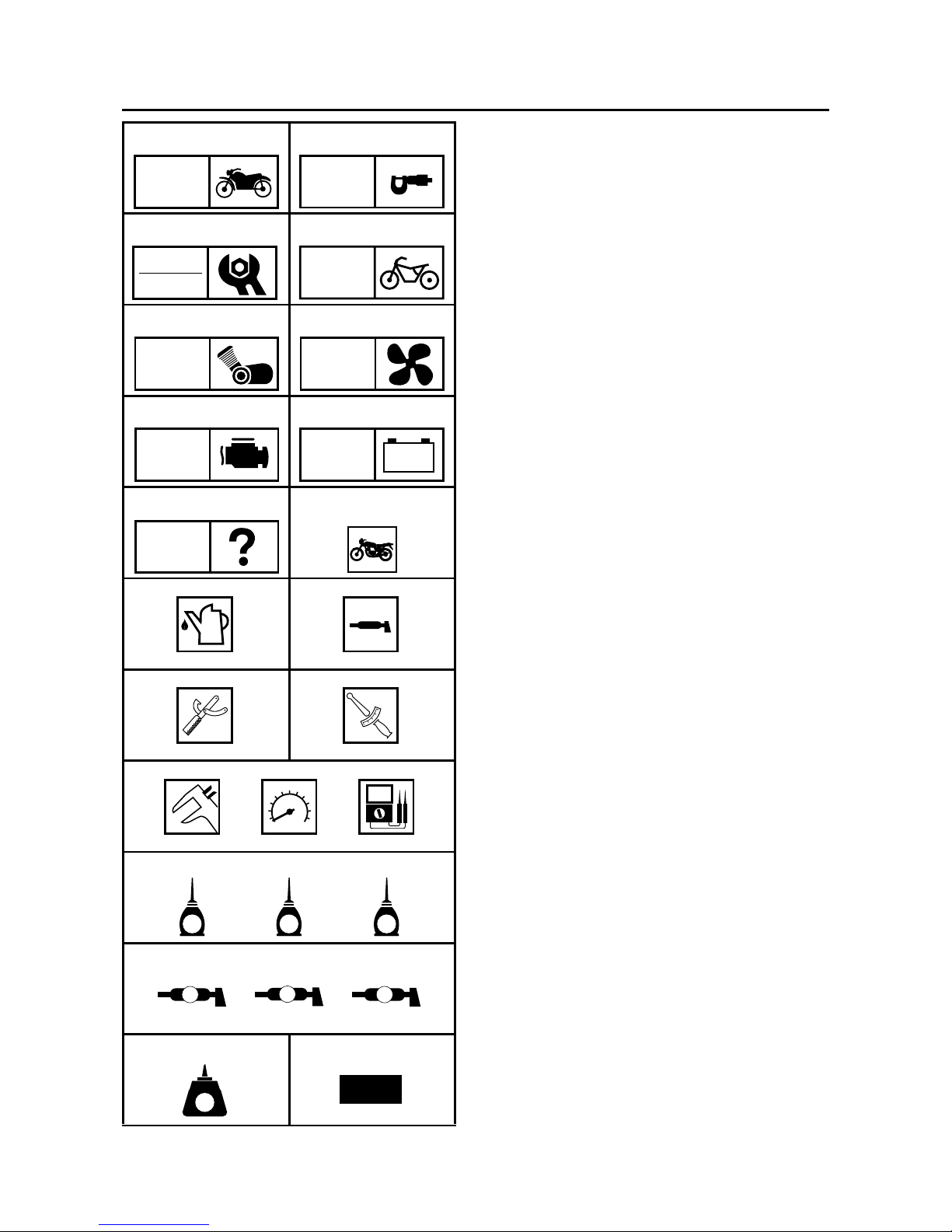
EAS00008
SYMBOLS
The following symbols are not relevant to
every vehicle.
Symbols 1 to 9 indicate the subject of each
chapter.
1
General information
2
Specifications
3
Periodic checks and adjustments
4
Chassis
5
Engine
6
Cooling system
7
Fuel injection system
8
Electrical system
9
Troubleshooting
Symbols 0 to G indicate the following.
0
Serviceable with engine mounted
A
Filling fluid
B
Lubricant
C
Special tool
D
Tightening torque
E
Wear limit, clearance
F
Engine speed
G
Electrical data
Symbols H to M in the exploded diagrams
indicate the types of lubricants and lubrication
points.
H
Engine oil
I
Gear oil
J
Molybdenum-disulfide oil
K
Wheel-bearing grease
L
Lithium-soap-based grease
M
Molybdenum-disulfide grease
Symbols N to O in the exploded diagrams
indicate the following.
N
Apply locking agent (LOCTITE
®
)
O
Replace the part
12
34
56
78
90
AB
CD
EFG
HIJ
KLM
NO
GEN
INFO
SPEC
CHK
ADJ
CHAS
ENG
COOL
FI
–+
ELEC
TRBL
SHTG
T
R
.
.
E
G
M
B
LS
M
LT
New
Manuals by Motomatrix / www.motomatrix.co.uk / The Solution For Lost Motorcycle Coded Keys
email: info@motomatrix.co.uk

CONTENTS
SPECIFICATIONS
..............................................................................................1
GENERAL SPECIFICATIONS .....................................................................1
ENGINE SPECIFICATIONS.........................................................................2
CHASSIS SPECIFICATIONS....................................................................... 6
ELECTRICAL SPECIFICATIONS ................................................................ 8
TIGHTENING TORQUE ............................................................................... 8
ENGINE TIGHTENING TORQUES ....................................................... 8
CHASSIS TIGHTENING TORQUES ..................................................... 8
CABLE ROUTING ........................................................................................9
PERIODIC CHECKS AND ADJUSTMENTS
.................................................... 22
COWLING AND COVER ............................................................................ 22
COVER ................................................................................................ 22
COWLING............................................................................................ 23
FUEL TANK................................................................................................24
CHASSIS.................................................................................................... 26
ADJUSTING THE DRIVE CHAIN SLACK............................................ 26
CHECKING THE TIRES ...................................................................... 28
CHASSIS
..........................................................................................................32
REAR WHEEL, BRAKE DISC, AND REAR WHEEL SPROCKET............. 32
REAR WHEEL ..................................................................................... 32
REMOVING THE REAR WHEEL (XT660R) ........................................ 34
REMOVING THE REAR WHEEL (XT660X) ........................................ 35
INSTALLING THE REAR WHEEL (XT660R)....................................... 35
INSTALLING THE REAR WHEEL (XT660X)....................................... 36
SWINGARM AND DRIVE CHAIN............................................................... 38
ENGINE
............................................................................................................41
ENGINE REMOVAL ................................................................................... 41
EXHAUST PIPES AND MUFFLERS.................................................... 41
CYLINDER HEAD ...................................................................................... 42
CYLINDER AND PISTON ..........................................................................44
COOLING SYSTEM
..........................................................................................46
RADIATOR ................................................................................................. 46
FUEL INJECTION SYSTEM
.............................................................................48
FUEL INJECTION SYSTEM....................................................................... 48
WIRING DIAGRAM.............................................................................. 49
FAIL-SAFE ACTION TABLE................................................................ 50
DIAGNOSTIC MODE........................................................................... 52
TROUBLESHOOTING DETAILS......................................................... 58
ELECTRICAL SYSTEM
....................................................................................71
ELECTRICAL COMPONENTS................................................................... 71
XT660R(W)/XT660X(W) 2007 WIRING DIAGRAM
Manuals by Motomatrix / www.motomatrix.co.uk / The Solution For Lost Motorcycle Coded Keys
email: info@motomatrix.co.uk
– 1 –
SPEC
SPECIFICATIONS
GENERAL SPECIFICATIONS
Item Standard Limit
Model code XT660R: 5VK8 (Europe)
5VK9 (AUS)
XT660X: 10S1 (Europe)
10S2 (AUS)
----
----
----
----
Dimensions
Overall length 2,240 mm (88.2 in) (XT660R)
2,175 mm (85.6 in) (XT660X)
----
----
Overall width 845 mm (33.3 in) (XT660R)
860 mm (33.9 in) (XT660X)
----
----
Overall height 1,230 mm (48.4 in) (XT660R)
1,170 mm (46.1 in) (XT660X)
----
----
Seat height 865 mm (34.1 in) (XT660R)
875 mm (34.4 in) (XT660X)
----
----
Wheelbase 1,505 mm (59.3 in) (XT660R)
1,490 mm (58.7 in) (XT660X)
----
----
Minimum ground clearance 210 mm (8.27 in) (XT660R)
205 mm (8.07 in) (XT660X)
----
----
Minimum turning radius 2,400 mm (94.5 in) ----
GENERAL SPECIFICATIONS
Manuals by Motomatrix / www.motomatrix.co.uk / The Solution For Lost Motorcycle Coded Keys
email: info@motomatrix.co.uk
– 2 –
SPEC
ENGINE SPECIFICATIONS
ENGINE SPECIFICATIONS
Item Standard Limit
Engine
Engine type Liquid-cooled, 4-stroke, SOHC ---Displacement 660 cm
3
---Cylinder arrangement Forward-inclined single cylinder ---Bore × stroke 100.0 × 84.0 mm (3.94 × 3.31 in) ---Compression ratio 10.00 : 1 ---Engine idling speed 1,400 ~ 1,500 r/min ---Water temperature 80 °C (176 °F) ----
Oil temperature 55 ~ 65 °C (131 ~ 149 °F) ---Standard compression pressure
(at sea level)
650 kPa (6.5 kg/cm
2
, 92.4 psi)
at 800 r/min
----
Engine oil
Lubrication system Dry sump ---Recommended oil
SAE 10W30, SAE 10W-40, SAE 15W40,
SAE 20W40 or SAE 20W-50
Refer to the chart for engine oil grade.
----
Recommended engine oil grade API service SG type or higher, JASO
standard MA
----
Quantity
Total amount 2.90 L (2.55 Imp qt, 3.07 US qt) ---Periodic oil change 2.50 L (2.20 Imp qt, 2.64 US qt) ---With oil filter replacement 2.60 L (2.29 Imp qt, 2.75 US qt) ----
Oil pump
Oil pump type Trochoid ---Inner-rotor-to-outer-rotor-tip clearance
0.03 ~ 0.08 mm (0.0012 ~ 0.0031 in) 0.16 mm
(0.0063 in)
Outer-rotor-to-oil-pump-housing
clearance
0.09 ~ 0.15 mm (0.0035 ~ 0.0059 in) 0.22 mm
(0.0087 in)
Oil-pump-housing-to-inner-rotor-andouter-rotor clearance
0.03 ~ 0.08 mm (0.0012 ~ 0.0031 in) 0.15 mm
(0.0059 in)
-20 -10 0
10
20 30
40
50 ˚C
SAE 10W-30
SAE 15W-40
SAE 20W-40
SAE 20W-50
SAE 10W-40
Manuals by Motomatrix / www.motomatrix.co.uk / The Solution For Lost Motorcycle Coded Keys
email: info@motomatrix.co.uk
– 3 –
SPEC
ENGINE SPECIFICATIONS
Camshaft
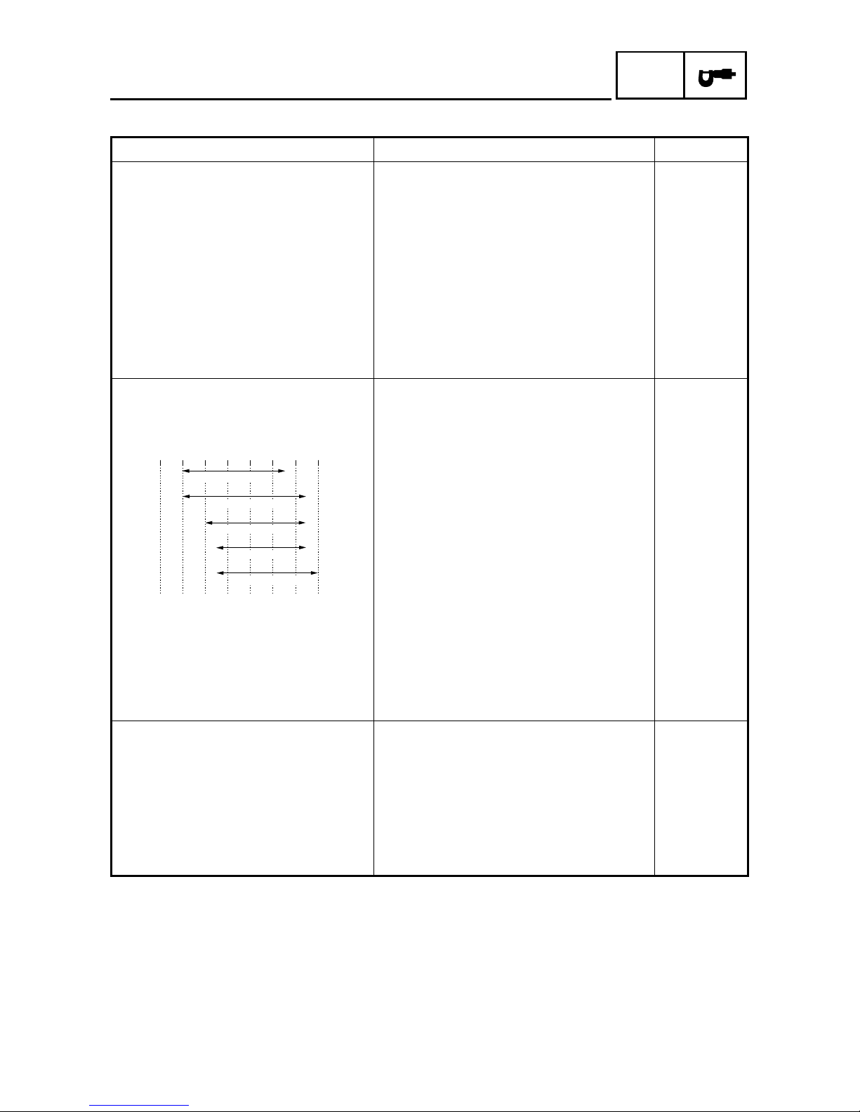
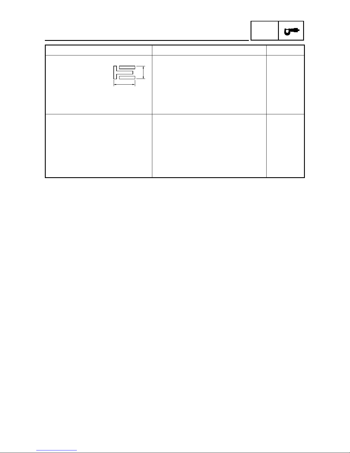
Drive system Chain drive (left) ---Intake camshaft lobe dimensions
Measurement A 43.488 ~ 43.588 mm (1.7121 ~ 1.7161 in) 43.388 mm
(1.7082 in)
Measurement B 36.959 ~ 37.059 mm (1.4551 ~ 1.4590 in) 36.859 mm
(1.4511 in)
Exhaust camshaft lobe dimensions
Measurement A 43.129 ~ 43.229 mm (1.6980 ~ 1.7019 in) 43.029 mm
(1.6941 in)
Measurement B 37.007 ~ 37.107 mm (1.4570 ~ 1.4609 in) 36.907 mm
(1.4530 in)
Valve timing
Intake - open (B.T.D.C.) 25° ----
Intake - closed (A.B.D.C.) 55° ---Exhaust - open (B.B.D.C.) 60° ----
Exhaust - closed (A.T.D.C.) 20° ---Overlap angle “A” 45° ----
Maximum camshaft runout ---- 0.040 mm
(0.0016 in)
Timing chain
Model/number of links 98XRH2010/126 ---Tensioning system Automatic ----
Item Standard Limit
A
B
A
B
Manuals by Motomatrix / www.motomatrix.co.uk / The Solution For Lost Motorcycle Coded Keys
email: info@motomatrix.co.uk
– 4 –
SPEC
ENGINE SPECIFICATIONS
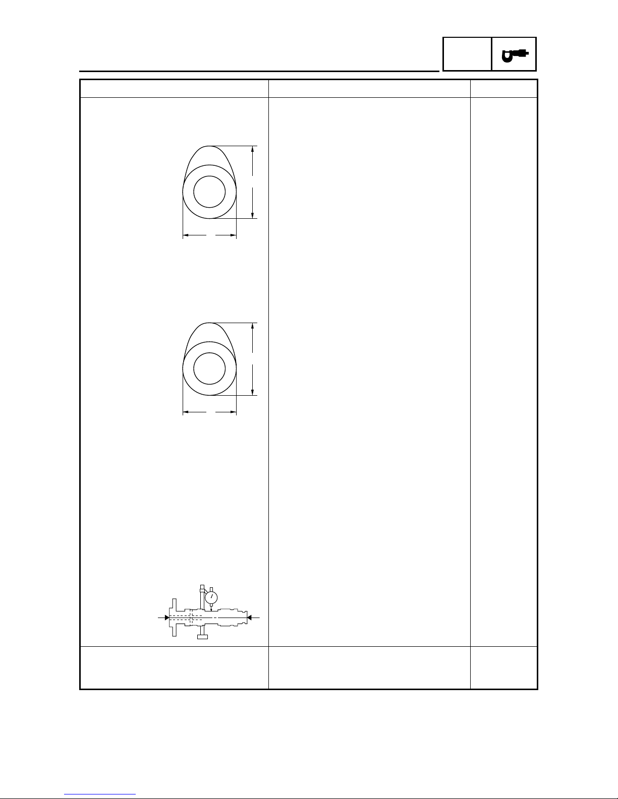
Piston
Piston-to-cylinder clearance 0.030 ~ 0.055 mm (0.0012 ~ 0.0022 in) 0.13 mm
(0.0051 in)
Diameter D 99.955 ~ 99.970 mm (3.9352 ~ 3.9358 in) ----
Height H 10.0 mm (0.39 in) ---Piston pin bore (in the piston)
Diameter 23.004 ~ 23.015 mm (0.9057 ~ 0.9061 in) 23.045 mm
(0.9073 in)
Offset 0.50 mm (0.0197 in) ---Offset direction Intake side ----
Piston pin
Outside diameter 22.991 ~ 23.000 (0.9052 ~ 0.9055 in) 22.971 mm
(0.9044 in)
Piston-pin-to-piston-pin-bore clearance
0.004 ~ 0.024 mm (0.0002 ~ 0.0009 in) 0.074 mm
(0.0029 in)
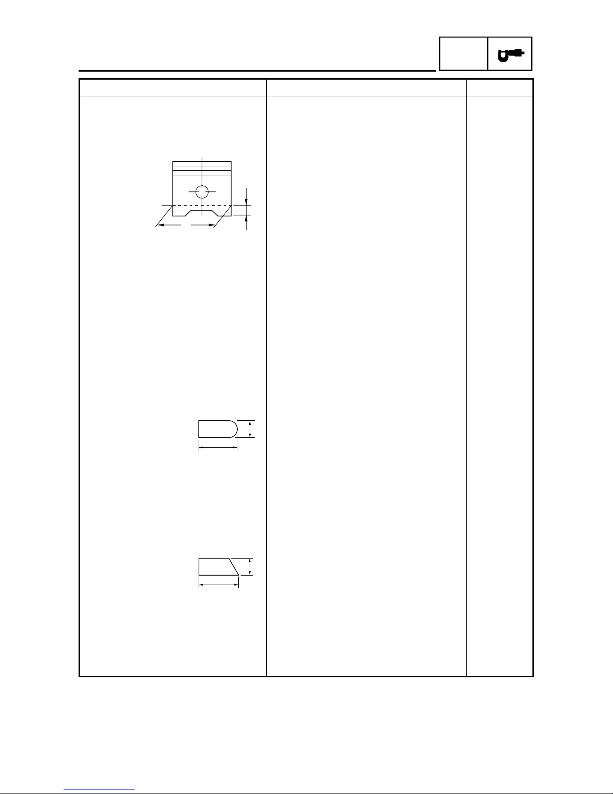
Piston rings
Top ring
Ring type Barrel ---Dimensions (B × T) 1.20 × 3.80 mm (0.047 × 0.150 in) ---End gap (installed) 0.20 ~ 0.35 mm (0.0079 ~ 0.0138 in) 0.60 mm
(0.0236 in)
Ring side clearance 0.030 ~ 0.080 mm (0.0012 ~ 0.0031 in) 0.13 mm
(0.0051 in)
2nd ring
Ring type Taper ---Dimensions (B × T) 1.20 × 4.00 mm (0.047 × 0.157 in) ---End gap (installed) 0.35 ~ 0.50 mm (0.0138 ~ 0.0197 in) 0.85 mm
(0.0335 in)
Ring side clearance 0.030 ~ 0.070 mm (0.0012 ~ 0.0028 in) 0.13 mm
(0.0051 in)
Item Standard Limit
H
D
T
B
B
T
Manuals by Motomatrix / www.motomatrix.co.uk / The Solution For Lost Motorcycle Coded Keys
email: info@motomatrix.co.uk
– 5 –
SPEC
ENGINE SPECIFICATIONS
Oil ring
Dimensions (B × T) 2.50 × 3.40 mm (0.098 × 0.134 in) ---End gap (installed) 0.20 ~ 0.70 mm (0.0079 ~ 0.0276 in) ---Ring side clearance 0.060 ~ 0.150 mm (0.0024 ~ 0.0059 in) ----
Throttle body
Model/manufacturer × quantity 44EHS/MIKUNI × 1 ---Intake vacuum pressure 37.6 ~ 40.2 kPa
(282 ~ 302 mmHg, 11.1 ~ 11.9 inHg)
----
Throttle cable free play (at the flange
of the throttle grip)
3.0 ~ 5.0 mm (0.12 in ~ 0.20 mm) ----
ID mark 5VK8 10 ---Throttle valve size #50 ----
Item Standard Limit
B
T
Manuals by Motomatrix / www.motomatrix.co.uk / The Solution For Lost Motorcycle Coded Keys
email: info@motomatrix.co.uk
– 6 –
SPEC
CHASSIS SPECIFICATIONS
CHASSIS SPECIFICATIONS
Item Standard Limit
Rear wheel
Wheel type Spoke wheel ---Rim
Size 17M/C × MT2.75 (XT660R)
17M/C × MT4.25 (XT660X)
----
----
Material Aluminum ----
Wheel travel 200.0 mm (7.87 in) (XT660R)
191.0 mm (7.52 in) (XT660X)
----
----
Wheel runout
Maximum radial wheel runout ---- 2.0 mm
(0.08 in)
Maximum lateral wheel runout ---- 2.0 mm
(0.08 in)
Wheel axle bending limit ---- 0.25 mm
(0.01 in)
Front tire
Tire type With tube ---Size 90/90-21M/C 54S, 90/90-21M/C 54T
(XT660R)
120/70R 17M/C 58 H, 120/70ZR 17M/C
58W, 120/70ZR 17M/C 58W (XT660X)
----
----
Model/manufacturer TOURANCE FRONT/METZELER,
SIRAC/MICHELIN (XT660R)
DRAGON/PIRELLI, SPORTEC M1/
METZELER, RADIAL PILOT SPORT/
MICHELIN (XT660X)
----
----
Tire pressure (cold)
0 ~ 90 kg (0 ~ 198 lb) 200 kPa (2.00 kgf/cm, 29 psi) (XT660R)
210 kPa (2.10 kgf/cm, 30 psi) (XT660X)
----
----
90 (198 lb) ~ Maximum load* 200 kPa (2.00 kgf/cm, 29 psi) (XT660R)
220 kPa (2.20 kgf/cm, 31 psi) (XT660X)
----
---* Load is the total weight of the cargo,
rider, passenger and accessories.
Off-road riding 200 kPa (2.00 kgf/cm, 29 psi) (XT660R) ----
Minimum tire tread depth ---- 1.6 mm
(0.063 in)
Manuals by Motomatrix / www.motomatrix.co.uk / The Solution For Lost Motorcycle Coded Keys
email: info@motomatrix.co.uk
– 7 –
SPEC
CHASSIS SPECIFICATIONS
Rear tire
Tire type With tube ---Size 130/80-17M/C 65S, 130/80-17M/C 65T
(XT660R)
160/60R 17M/C 69H, 160/60ZR 17M/C
69W, 160/60ZR 17M/C 69W (XT660X)
----
----
Model/manufacturer TOURANCE/METZELER, SIRAC A/
MICHELIN (XT660R)
DRAGON/PIRELLI, SPORTEC M1/
METZELER, RADIAL PILOT SPORT/
MICHELIN (XT660X)
----
----
Tire pressure (cold)
0 ~ 90 kg (0 ~ 198 lb) 200 kPa (2.00 kgf/cm, 29 psi) (XT660R)
210 kPa (2.10 kgf/cm, 30 psi) (XT660X)
----
----
90 (198 lb) ~ Maximum load* 225 kPa (2.25 kgf/cm, 33 psi) (XT660R)
230 kPa (2.30 kgf/cm, 33 psi) (XT660X)
----
---* Load is the total weight of the cargo,
rider, passenger and accessories.
Off-road riding 200 kPa (2.00 kgf/cm, 29 psi) (XT660R) ----
Minimum tire tread depth ---- 1.6 mm
(0.063 in)
Item Standard Limit
Manuals by Motomatrix / www.motomatrix.co.uk / The Solution For Lost Motorcycle Coded Keys
email: info@motomatrix.co.uk
– 8 –
SPEC
ELECTRICAL SPECIFICATIONS/
TIGHTENING TORQUE
ELECTRICAL SPECIFICATIONS
TIGHTENING TORQUE
ENGINE TIGHTENING TORQUES
CHASSIS TIGHTENING TORQUES
Item Standard Limit
System voltage 12 V ----
Ignition system
Ignition system type Transistorized coil ignition (digital) ---Ignition timing 5.0° BTDC at 1,450 r/min ---Advancer type Electric ---Crankshaft position senor resistance/
color
192 ~ 288 Ω at 20 °C (68 °F)
blue/yellow–green/white
----
Transistorized coil ignition unit
model/manufacturer
TBDF36/DENSO ----
Part to be tightened Part name
Thread
size
Q’ty
Tightening torque
Remarks
Nm m · kg ft · lb
O
2
sensor — M18 1 45 4.5 32
O
2
sensor protector Bolt M6 2 10 1.0 7.2
Part to be tightened
Thread
size
Tightening torque
Remarks
Nm m · kg ft · lb
Engine mounting:
Engine upper bracket and frame M10 65 6.5 47
Engine front bracket and frame M10 65 6.5 47
Engine front bracket and engine M10 65 6.5 47
Engine and frame M10 65 6.5 47
Manuals by Motomatrix / www.motomatrix.co.uk / The Solution For Lost Motorcycle Coded Keys
email: info@motomatrix.co.uk
– 9 –
SPEC
CABLE ROUTING
EAS00035
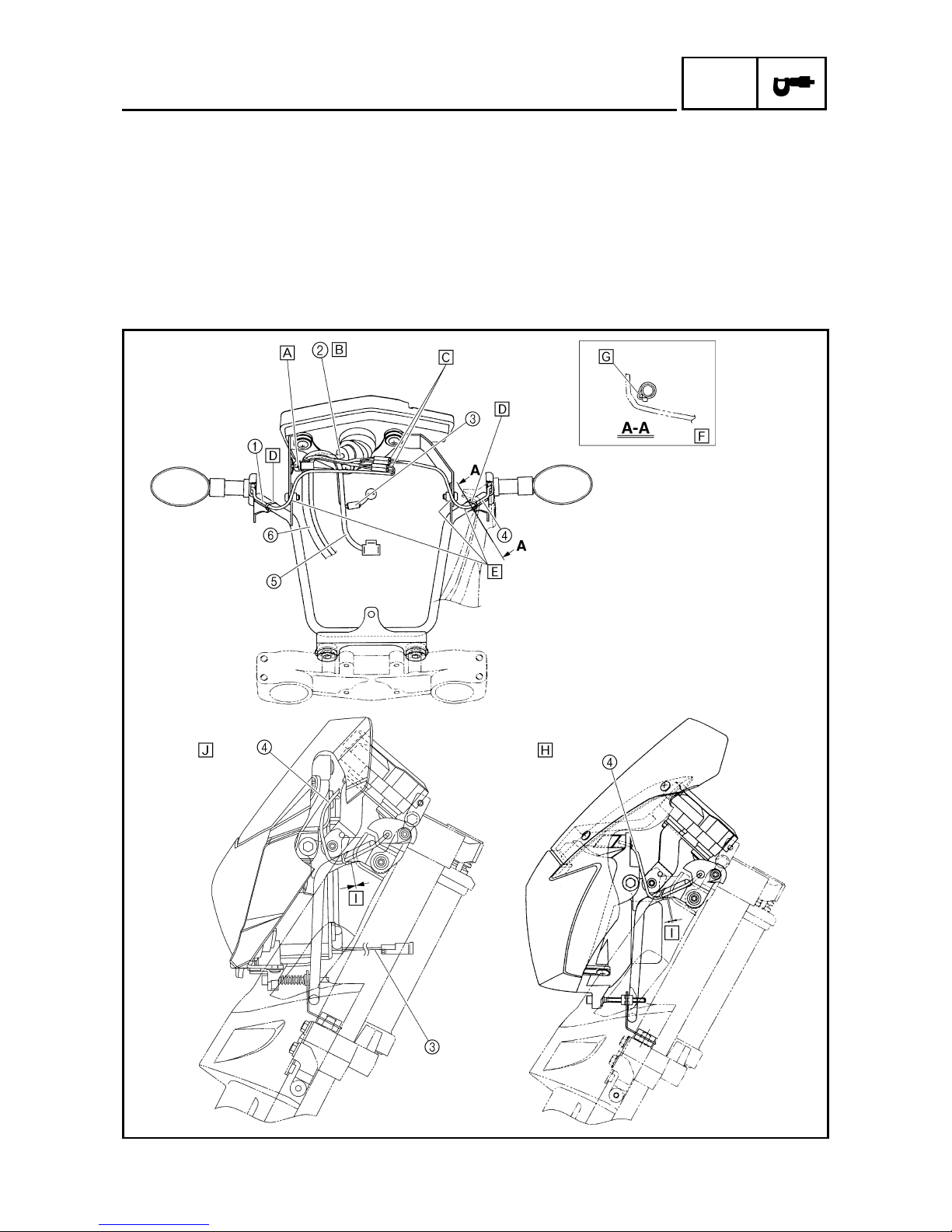
CABLE ROUTING
1
Front turn signal light lead (right)
2
Meter assembly lead
3
Auxiliary light lead
4
Front turn signal light lead (left)
5
Headlight lead
6
Sub-wire harness
È
Fasten the sub-wire harness and meter assembly lead with a plastic band. Fasten the sub-wire
harness at the white tape. Face the end of the
plastic band forward.
É
Make sure that there is no slack in the meter
assembly lead between the meter assembly and
the plastic band. The rubber boot on the meter
assembly can be bent as shown.
Manuals by Motomatrix / www.motomatrix.co.uk / The Solution For Lost Motorcycle Coded Keys
email: info@motomatrix.co.uk

– 10 –
SPEC
CABLE ROUTING
Ê Place the slack of the left and right front turn sig-
nal light leads between the headlight assembly
and front cowling assembly.
Ë Fasten the left and right front turn signal light
leads to the headlight stay with a plastic locking
tie, and then cut off the excess end of tie.
Ì Pass the left and right front turn signal light leads
in front of the headlight stay.
Í Only the left side is shown in this illustration.
Route the right front turn signal light lead in the
same way.
Î Pass the left and right front turn signal light leads
between the headlight stay and front fork protector.
Ï XT660R
Ð 0 ~ 5 mm (0 ~ 0.20 in) for both left and right
sides
Ñ XT660X
Manuals by Motomatrix / www.motomatrix.co.uk / The Solution For Lost Motorcycle Coded Keys
email: info@motomatrix.co.uk
– 11 –
SPEC
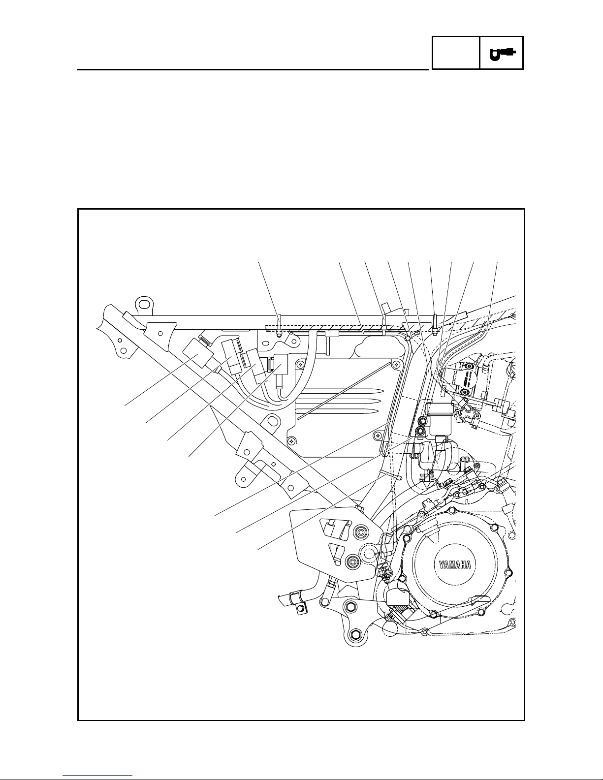
CABLE ROUTING
1 Rear brake light switch lead
2 Negative battery lead
3 Lean angle cut-off switch lead
4 Throttle position sensor lead
5 Coolant temperature sensor lead
6 Turn signal/hazard relay
7 Headlight relay
8 Radiator fan motor relay
9 Relay unit
È Fasten the wire harness and negative battery
lead to the frame with a plastic locking tie.
É Fasten the wire harness, negative battery lead,
and rear brake light switch lead to the frame with
a plastic locking tie.
Ê Fasten the rear brake light switch lead to the
frame with a plastic locking tie.
Ë Fasten the wire harness to the frame at the
white tape with a plastic locking tie.
9
8
7
6
Í
È 1 ÉÊ2 Ë 345
Ì
Ê
Manuals by Motomatrix / www.motomatrix.co.uk / The Solution For Lost Motorcycle Coded Keys
email: info@motomatrix.co.uk

– 12 –
SPEC
CABLE ROUTING
Ì Route the negative battery lead behind the lean
angle cut-off switch bracket.
Í Route the rear brake light switch lead between
the air filter case and the frame.
9
8
7
6
Í
È 1 ÉÊ2 Ë 345
Ì
Ê
Manuals by Motomatrix / www.motomatrix.co.uk / The Solution For Lost Motorcycle Coded Keys
email: info@motomatrix.co.uk

– 13 –
SPEC
CABLE ROUTING
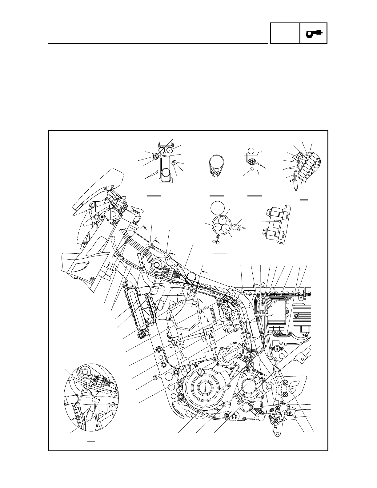
1 Neutral switch connector
2 Crankshaft position sensor
coupler
3 A.C. magneto coupler
4 Speed sensor lead
5 Intake air temperature sensor
lead
6 ECU lead
7 Starter motor lead
8 Sidestand switch lead
9 Speed sensor
0 A.C. magneto lead
A Oil tank breather hose
B Oil delivery hose 2
C Radiator fan motor lead
D Throttle cable
E Headlight lead
F Meter assembly lead
G Left handlebar switch lead
H Right handlebar switch lead
I Front brake light switch lead
J Clutch switch lead
K Immobilizer unit lead
L Clutch cable
M Main switch lead
N O
2
sensor lead
O Air-filter-to-air-cut-off-valve
hose
P Wire harness
A-A B-B C-C
D
J
I
G
H
E
C
F
B
B
C
C
E
D
É
Ê
Ë
Ì
12
34 5
76
A
A
E
F
F
F-F
E-E
Ó
Ò
Ñ
Ð
Ï
ÎÍ
8
D
C
B
A
098
È
D
B
G
H
I
J
K
L
M
D
E
F
P
A
D
B
O
Ô
N
G
G
N
Manuals by Motomatrix / www.motomatrix.co.uk / The Solution For Lost Motorcycle Coded Keys
email: info@motomatrix.co.uk

– 14 –
SPEC
CABLE ROUTING
È Fasten the left handlebar switch lead, right han-
dlebar switch lead, headlight lead, meter assembly lead, front brake light switch lead, and clutch
switch lead to the frame with a plastic locking tie.
To fasten the leads, connect the couplers, and
then turn the handlebar completely to the right.
É Fasten the left handlebar switch lead, right han-
dlebar switch lead, headlight lead, meter assembly lead, front brake light switch lead, clutch
switch lead, radiator fan motor lead, and throttle
cables with a plastic band. To fasten the leads
and cables, connect the couplers, and then turn
the handlebar completely to the right.
Ê Route the oil tank breather hose on the outside
of the throttle cables.
A-A B-B C-C
D
J
I
G
H
E
C
F
B
B
C
C
E
D
É
Ê
Ë
Ì
12
34 5
76
A
A
E
F
F
F-F
E-E
Ó
Ò
Ñ
Ð
Ï
ÎÍ
8
D
C
B
A
098
È
D
B
G
H
I
J
K
L
M
D
E
F
P
A
D
B
O
Ô
N
G
G
N
Manuals by Motomatrix / www.motomatrix.co.uk / The Solution For Lost Motorcycle Coded Keys
email: info@motomatrix.co.uk

– 15 –
SPEC
CABLE ROUTING
Ë Fasten the wire harness to the frame at the
white tape with a plastic locking tie.
Ì Fasten the starter motor lead to the frame with a
plastic locking tie.
Í Fasten the sidestand switch lead to the frame
with a plastic locking tie.
Î Route the sidestand switch lead at the front end
of the left side heel plate.
Ï Fasten the neutral switch lead, crankshaft posi-
tion sensor lead, sidestand switch lead, speed
sensor lead, starter motor lead, and A.C. magneto lead with a plastic band.
Ð Fasten the neutral switch lead, crankshaft posi-
tion sensor lead, sidestand switch lead, speed
sensor lead, and starter motor lead with a plastic
band.
Ñ Fasten the air-filter-to-air-cut-off-valve hose, oil
tank breather hose, and oil delivery hose 2 with
a plastic clamp.
A-A B-B C-C
D
J
I
G
H
E
C
F
B
B
C
C
E
D
É
Ê
Ë
Ì
12
34 5
76
A
A
E
F
F
F-F
E-E
Ó
Ò
Ñ
Ð
Ï
ÎÍ
8
D
C
B
A
098
È
D
B
G
H
I
J
K
L
M
D
E
F
P
A
D
B
O
Ô
N
G
G
N
Manuals by Motomatrix / www.motomatrix.co.uk / The Solution For Lost Motorcycle Coded Keys
email: info@motomatrix.co.uk
– 16 –
SPEC
CABLE ROUTING
Ò Fasten the wire harness, air-filter-to-air-cut-off-
valve hose, and oil delivery hose 2 with a plastic
clamp.
Ó Fasten the left handlebar switch lead, right han-
dlebar switch lead, headlight lead, meter assembly lead, front brake light switch lead, and clutch
switch lead with a plastic band.
Turn the handlebar completely to the right, and
then fasten the left handlebar switch lead, right
handlebar switch lead, headlight lead, meter
assembly lead, front brake light switch lead, and
clutch switch lead next to the steering head pipe
with the plastic band. Be sure to connect the
couplers before fastening the leads.
Ô Fasten the O
2
sensor lead and air-filter-to-aircut-off-valve hose with a holder as shown in the
illustration.
A-A B-B C-C
D
J
I
G
H
E
C
F
B
B
C
C
E
D
É
Ê
Ë
Ì
12
34 5
76
A
A
E
F
F
F-F
E-E
Ó
Ò
Ñ
Ð
Ï
ÎÍ
8
D
C
B
A
098
È
D
B
G
H
I
J
K
L
M
D
E
F
P
A
D
B
O
Ô
N
G
G
N
Manuals by Motomatrix / www.motomatrix.co.uk / The Solution For Lost Motorcycle Coded Keys
email: info@motomatrix.co.uk
– 17 –
SPEC
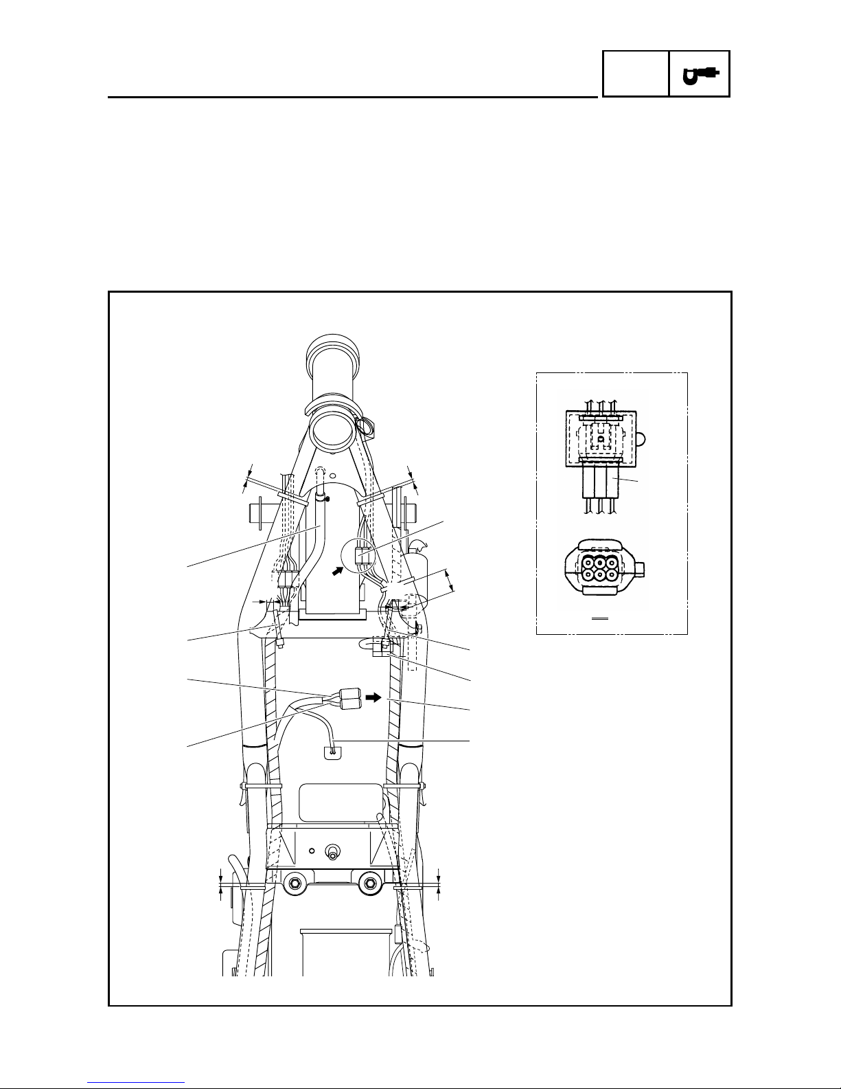
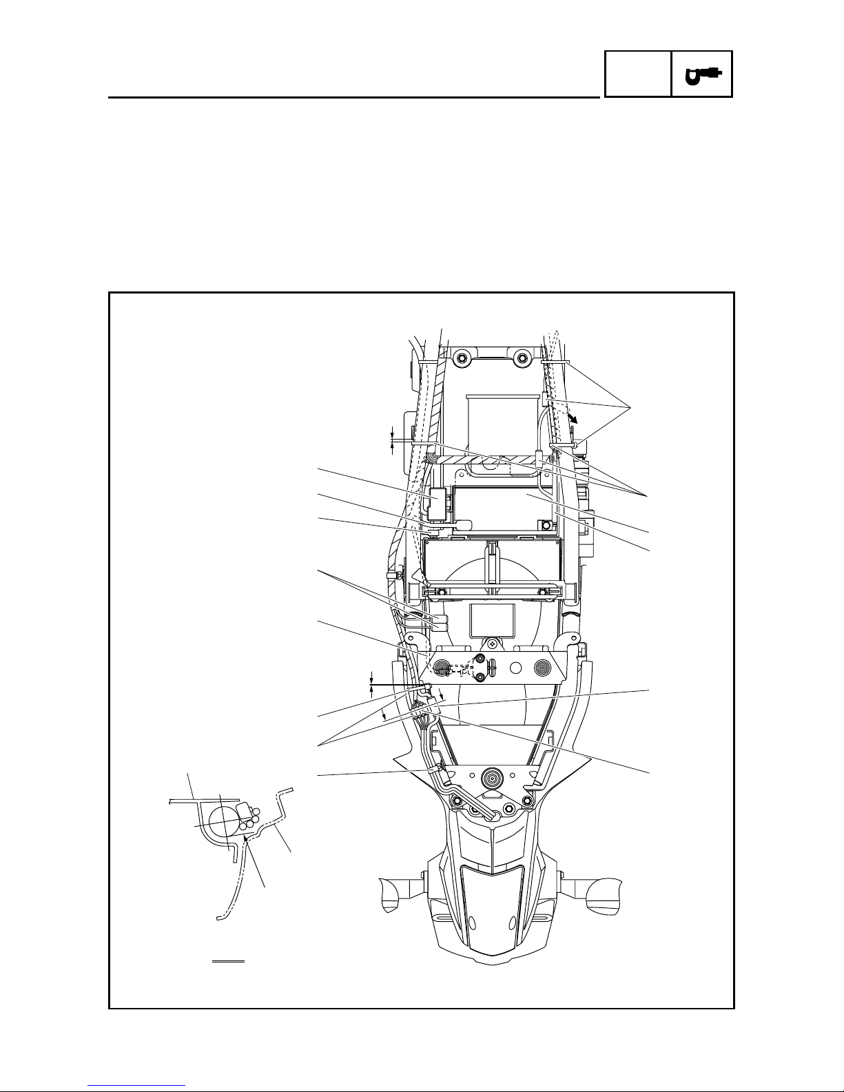
1 Immobilizer unit coupler
2 Intake air temperature sensor
3 Fuel injector lead
4 Fuel pump lead
5 Fuel sender lead
6 Oil tank breather hose
È 0 ~ 10 mm (0 ~ 0.39 in)
É 30 ~ 40 mm (1.18 ~ 1.57 in)
Ê 5 ~ 15 mm (0.20 ~ 0.59 in)
Ë Fasten the wire harness to the frame with a plas-
tic locking tie.
Ì To the fuel tank
Í 0 ~ 5 mm (0 ~ 0.20 in)
Î Europe, ZA
ÍÍ
Ë
2
Ë
5
4
Ì
3
È
È
Ê
É
6
1
A
Ê
1
A
Î
CABLE ROUTING
Manuals by Motomatrix / www.motomatrix.co.uk / The Solution For Lost Motorcycle Coded Keys
email: info@motomatrix.co.uk

– 18 –
SPEC
1 Battery
2 Negative battery lead
3 Tail/brake light coupler
4 Rear turn signal light connector
5 Seat lock cable
6 Anti-theft alarm coupler
7 Fuse box 2
8 Positive battery lead
9 Fuse box 1
0 Rear fender
A Rear fender cover
È Fasten the tail/brake light lead with two plastic
locking ties so that the coupler is positioned to
the inside of where the relays (turn signal/hazard
relay, headlight relay, radiator fan motor relay,
and relay unit) branch off from the wire harness.
É To relays (turn signal/hazard relay, headlight
relay, radiator fan motor relay, and relay unit)
A-A
Ï
Î
1
2
3
4
9
8
7
6
5
A
Í
Ì
Ð
Ë
È
A
A
É
0
Ê
CABLE ROUTING
Manuals by Motomatrix / www.motomatrix.co.uk / The Solution For Lost Motorcycle Coded Keys
email: info@motomatrix.co.uk
– 19 –
SPEC
CABLE ROUTING
Ê Fasten the wire harness with plastic locking ties,
making sure to install the ties around the taped
sections of the harness. Do not install the plastic
locking ties around the sections of the leads that
are not covered by the tape and do not fasten
the negative battery lead coupler.
Ë Fasten the rear turn signal light leads and tail/
brake light lead with a lead holder.
Ì Connect the couplers so that they are not
pinched between the rear fender and rear fender
cover.
Í Fasten the wire harness to the frame with a plas-
tic locking tie.
Î 0 ~ 5 mm (0 ~ 0.20 in)
Ï 0 ~ 10 mm (0 ~ 0.39 in)
Ð The tail/brake light coupler and the rear turn sig-
nal light lead should not be lower than the line
shown in the illustration.
A-A
Ï
Î
1
2
3
4
9
8
7
6
5
A
Í
Ì
Ð
Ë
È
A
A
É
0
Ê
Manuals by Motomatrix / www.motomatrix.co.uk / The Solution For Lost Motorcycle Coded Keys
email: info@motomatrix.co.uk