

Page 1

2004
XT660R(S)
XT660X(S)
5VK1-AE1
SERVICE MANUAL
Page 2

Page 3

EAS00000
XT660R(S)/XT660X(S) 2004
SERVICE MANUAL
©2003 by MBK Industrie
First edition, December 2003
All rights reserved.
Any reproduction or unauthorized use
without the written permission of
MBK Industrie
is expressly prohibited.
Page 4
EAS00002
NOTICE
This manual was produced by MBK Industrie primarily for use by Yamaha dealers and their qualified mechanics. It is not possible to include all the knowledge of a mechanic in one manual. Therefore, anyone who uses this book to perform maintenance and repairs on Yamaha vehicles should
have a basic understanding of mechanics and the techniques to repair these types of vehicles.
Repair and maintenance work attempted by anyone without this knowledge is likely to render the
vehicle unsafe and unfit for use.
Yamaha is continually striving to improve all its models. Modifications and significant changes in
specifications or procedures will be forwarded to all authorized Yamaha dealers and will appear in
future editions of this manual where applicable.
NOTE:
_
Designs and specifications are subject to change without notice.
EAS00004
IMPORTANT MANUAL INFORMATION
Particularly important information is distinguished in this manual by the following.
The Safety Alert Symbol means ATTENTION! BECOME ALERT! YOUR
SAFETY IS INVOLVED!
WARNING
CAUTION:
NOTE:
Failure to follow WARNING instructions could result in severe injury or death
to the motorcycle operator, a bystander or a person checking or repairing
the motorcycle.
A CAUTION indicates special precautions that must be taken to avoid damage to the motorcycle.
A NOTE provides key information to make procedures easier or clearer.
Page 5

EAS00007
HOW TO USE THIS MANUAL
This manual is intended as a handy, easy-to-read reference book for the mechanic. Comprehensive
explanations of all installation, removal, disassembly, assembly, repair and check procedures are
laid out with the individual steps in sequential order.
1
The manual is divided into chapters. An abbreviation and symbol in the upper right corner of
each page indicate the current chapter.
Refer to “SYMBOLS”.
2
Each chapter is divided into sections. The current section title is shown at the top of each page,
except in Chapter 3 (“PERIODIC CHECKS AND ADJUSTMENTS”), where the sub-section
title(s) appears.
3
Sub-section titles appear in smaller print than the section title.
4
To help identify parts and clarify procedure steps, there are exploded diagrams at the start of
each removal and disassembly section.
5
Numbers are given in the order of the jobs in the exploded diagram. A circled number indicates a
disassembly step.
6
Symbols indicate parts to be lubricated or replaced.
Refer to “SYMBOLS”.
7
A job instruction chart accompanies the exploded diagram, providing the order of jobs, names of
parts, notes in jobs, etc.
8
Jobs requiring more information (such as special tools and technical data) are described sequentially.
Page 6

12
GEN
SPEC
INFO
34
CHK
CHAS
ADJ
56
ENG
78
COOL
EAS00008
SYMBOLS
The following symbols are not relevant to
every vehicle.
Symbols 1 to 9 indicate the subject of each
chapter.
General information
1
Specifications
2
Periodic checks and adjustments
3
Chassis
4
Engine
5
Cooling system
6
Fuel injection system
7
Electrical system
8
Troubleshooting
9
FI
90
ELEC
–+
TRBL
SHTG
AB
CD
T
.
R
.
EFG
HIJ
Symbols 0 to G indicate the following.
Serviceable with engine mounted
0
Filling fluid
A
Lubricant
B
Special tool
C
Tightening torque
D
Wear limit, clearance
E
Engine speed
F
Electrical data
G
Symbols H to M in the exploded diagrams
indicate the types of lubricants and lubrication
points.
LS
G
M
M
New
E
KLM
B
NO
LT
Engine oil
H
Gear oil
I
Molybdenum-disulfide oil
J
Wheel-bearing grease
K
Lithium-soap-based grease
L
Molybdenum-disulfide grease
M
Symbols N to O in the exploded diagrams
indicate the following.
®
Apply locking agent (LOCTITE
N
Replace the part
O
)
Page 7

EAS00010
– +
TABLE OF CONTENTS
GENERAL INFORMATION
SPECIFICATIONS
PERIODIC CHECKS AND
ADJUSTMENTS
CHASSIS
ENGINE
GEN
INFO
SPEC
CHK
ADJ
CHAS
ENG
1
2
3
4
5
COOLING SYSTEM
FUEL INJECTION SYSTEM
ELECTRICAL SYSTEM
TROUBLESHOOTING
COOL
FI
ELEC
TRBL
SHTG
6
7
8
9
Page 8

Page 9

GEN
INFO
1
Page 10

CHAPTER 1
GENERAL INFORMATION
GEN
INFO
MOTORCYCLE IDENTIFICATION
VEHICLE IDENTIFICATION NUMBER .....................................................1-1
MODEL LABEL..........................................................................................1-1
FEATURES
OUTLINE ...................................................................................................1-2
FI SYSTEM................................................................................................ 1-3
IMPORTANT INFORMATION
PREPARATION FOR REMOVAL AND DISASSEMBLY........................... 1-4
REPLACEMENT PARTS...........................................................................1-4
GASKETS, OIL SEALS AND O-RINGS .................................................... 1-4
LOCK WASHERS/PLATES AND COTTER PINS .....................................1-5
BEARINGS AND OIL SEALS ....................................................................1-5
CIRCLIPS ..................................................................................................1-5
CHECKING THE CONNECTIONS
SPECIAL TOOLS
......................................................................................................1-2
............................................................................................1-7
..................................................................1-1
.........................................................................1-4
..................................................................1-6
Page 11

GEN
INFO
Page 12

MOTORCYCLE IDENTIFICATION
EAS00014
GENERAL INFORMATION
MOTORCYCLE IDENTIFICATION
EAS00017
VEHICLE IDENTIFICATION NUMBER
The vehicle identification number 1 is
stamped into the right side of the steering head
pipe.
EAS00018
MODEL LABEL
The model label 1 is affixed to the frame. This
information will be needed to order spare
parts.
GEN
INFO
1 - 1
Page 13
GEN
FEATURES
EAS00019
FEATURES
EAS00896
OUTLINE
The main function of a fuel supply system is to provide fuel to the combustion chamber at the optimum air-fuel ratio in accordance with the engine operating conditions and the atmospheric temperature. In a conventional carburetor system, the air-fuel ratio of the mixture that is supplied to the
combustion chamber is created by the volume of the intake air and the fuel that is metered by the jet
used in the respective chamber.
Despite the same volume of intake air, the fuel volume requirement varies with the engine operating
conditions, such as acceleration, deceleration, or operation under a heavy load. Carburetors that
meter the fuel through the use of jets have been provided with various auxiliary devices, so that an
optimum air-fuel ratio can be achieved to accommodate the constant changes in the operating conditions of the engine.
As the requirements for engines to deliver more performance and cleaner exhaust gases increase,
it becomes necessary to control the air-fuel ratio in a more precise and finely tuned manner. To
accommodate this need, this model has adopted an electronically controlled fuel injection (FI) system in place of a conventional carburetor system. This system can achieve an optimum air-fuel ratio
required by the engine at all times by using a microprocessor that regulates the fuel injection volume
according to the engine operating conditions detected by various sensors.
Adoption of the FI system has resulted in a highly precise fuel supply, improved engine response,
better fuel economy, and reduced exhaust emissions. Furthermore, the air induction system (AI system) has been placed under computer control together with the FI system in order to realize cleaner
exhaust gases.
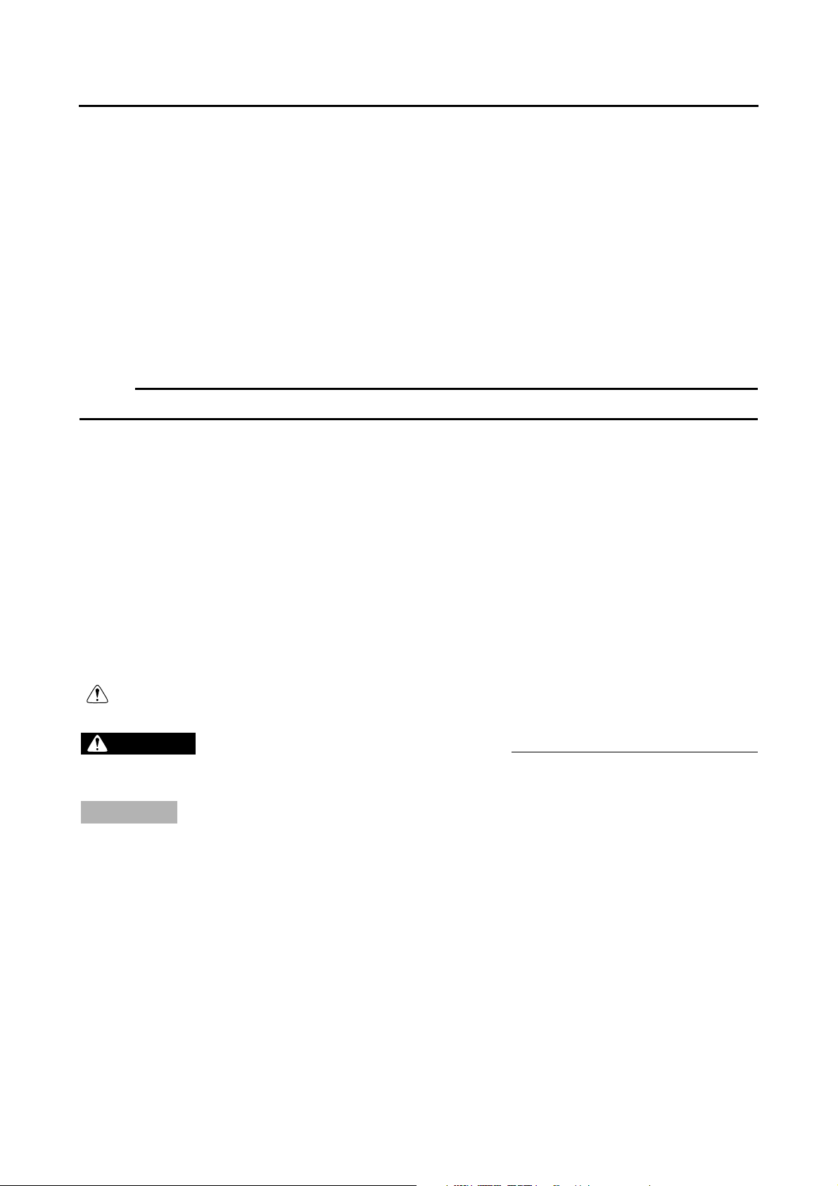
INFO
K
Air cut-off valve
1
Air induction system
2
solenoid
Engine trouble warn-
3
ing light
Fuel tank
4
Fuel pump
5
Fuel hose
6
12
J
34
Fuel injector
7
Throttle position sen-
8
sor
Intake air temperature
9
sensor
Air filter case
0
Fuel injection system
A
relay
567890A
B
C
DEFGHI
Battery
B
Catalytic converter
C
ECU
D
Lean angle cut-off
E
switch
Fast idle unit
F
Crankshaft position
G
sensor
Coolant temperature
H
sensor
Spark plug
I
Intake air pressure
J
sensor
Ignition coil
K
1 - 2
Page 14

GEN
FEATURES
EAS00897
FI SYSTEM
The fuel pump delivers fuel to the injector via the fuel filter. The pressure regulator maintains the
fuel pressure that is applied to the injector at 324 kPa (3.24 kg/cm
manifold pressure. Accordingly, when the energizing signal from the ECU energizes the injector, the
fuel passage opens, causing the fuel to be injected into the intake manifold only during the time the
passage remains open. Therefore, the longer the length of time the injector is energized (injection
duration), the greater the volume of fuel that is supplied. Conversely, the shorter the length of time
the injector is energized (injection duration), the lesser the volume of fuel that is supplied.
The injection duration and the injection timing are controlled by the ECU. Signals that are input from
the throttle position sensor, crankshaft position sensor, intake air pressure sensor, intake air temperature sensor, and coolant temperature sensor enable the ECU to determine the injection duration. The injection timing is determined through the signal from the crankshaft position sensor. As a
result, the volume of fuel that is required by the engine can be supplied at all times in accordance
with the driving conditions.
Illustration is for reference only.
2
, 46.1 psi) higher than the intake
INFO
Fuel pump
1
Pressure regulator
2
Fuel injector
3
Throttle body
4
È
#1
3
Intake air temperature
5
sensor
Throttle position sen-
6
sor
Intake air pressure
7
sensor
6
9
É
5
7
4
8
Ê
0
ECU
8
Coolant temperature
9
sensor
Crankshaft position
0
sensor
2
1
Fuel system
È
Air system
É
Control system
Ê
1 - 3
Page 15
IMPORTANT INFORMATION
EAS00020
IMPORTANT INFORMATION
PREPARATION FOR REMOVAL AND
DISASSEMBLY
1. Before removal and disassembly, remove all
dirt, mud, dust and foreign material.
2. Use only the proper tools and cleaning
equipment.
Refer to “SPECIAL TOOLS”.
3. When disassembling, always keep mated
parts together. This includes gears, cylinders, pistons and other parts that have been
“mated” through normal wear. Mated parts
must always be reused or replaced as an
assembly.
4. During disassembly, clean all of the parts
and place them in trays in the order of disassembly. This will speed up assembly and
allow for the correct installation of all parts.
5. Keep all parts away from any source of fire.
GEN
INFO
EAS00021
REPLACEMENT PARTS
Use only genuine Yamaha parts for all
replacements. Use oil and grease recommended by Yamaha for all lubrication jobs.
Other brands may be similar in function and
appearance, but inferior in quality.
EAS00022
GASKETS, OIL SEALS AND O-RINGS
1. When overhauling the engine, replace all
gaskets, seals and O-rings. All gasket surfaces, oil seal lips and O-rings must be
cleaned.
2. During reassembly, properly oil all mating
parts and bearings and lubricate the oil seal
lips with grease.
1 - 4
Page 16

IMPORTANT INFORMATION
EAS00023
LOCK WASHERS/PLATES AND COTTER
PINS
After removal, replace all lock washers/plates
1
and cotter pins. After the bolt or nut has
been tightened to specification, bend the lock
tabs along a flat of the bolt or nut.
EAS00024
BEARINGS AND OIL SEALS
Install bearings and oil seals so that the manufacturer’s marks or numbers are visible. When
installing oil seals, lubricate the oil seal lips
with a light coat of lithium-soap-based grease.
Oil bearings liberally when installing, if appropriate.
Oil seal
1
GEN
INFO
CAUTION:
_
Do not spin the bearing with compressed
air because this will damage the bearing
surfaces.
Bearing
1
EAS00025
CIRCLIPS
Before reassembly, check all circlips carefully
and replace damaged or distorted circlips.
Always replace piston pin clips after one use.
When installing a circlip 1, make sure the
sharp-edged corner 2 is positioned opposite
the thrust 3 that the circlip receives.
Shaft
4
1 - 5
Page 17

CHECKING THE CONNECTIONS
EAS00026
CHECKING THE CONNECTIONS
Check the leads, couplers, and connectors for
stains, rust, moisture, etc.
1. Disconnect:
• lead
• coupler
• connector
2. Check:
• lead
• coupler
• connector
Moisture → Dry with an air blower.
Rust/stains → Connect and disconnect several times.
3. Check:
• all connections
Loose connection → Connect properly.
NOTE:
_
If the pin 1 on the terminal is flattened, bend it
up.
GEN
INFO
4. Connect:
• lead
• coupler
• connector
NOTE:
_
Make sure all connections are tight.
5. Check:
• continuity
(with the pocket tester)
Pocket tester
90890-03112
NOTE:
_
• If there is no continuity, clean the terminals.
• When checking the wire harness, perform
steps (1) to (3).
• As a quick remedy, use a contact revitalizer
available at most part stores.
1 - 6
Page 18

GEN
SPECIAL TOOLS
EAS00027
SPECIAL TOOLS
The following special tools are necessary for complete and accurate tune-up and assembly. Use
only the appropriate special tools as this will help prevent damage caused by the use of inappropriate tools or improvised techniques. Special tools, part numbers or both may differ depending on the
country.
When placing an order, refer to the list provided below to avoid any mistakes.
Tool No. Tool name/Function Illustration
Slide hammer bolt
Slide hammer bolt
90890-01083
Weight
90890-01084
90890-01135
Weight
These tools are used to remove or install
the rocker arm shafts.
Crankcase separating tool
This tool is used to remove the crankshaft.
INFO
Attachment
90890-01243
Compressor
90890-04019
90890-01268
Pot
90890-01274
Bolt
90890-01275
90890-01304
Valve spring compressor attachment
Valve spring compressor
These tools are used to remove or install
the valve assemblies.
Ring nut wrench
This tool is used to loosen or tighten the
steering ring nuts.
Crankshaft installer pot
Crankshaft installer bolt
These tools are used to install the crankshaft.
Piston pin puller set
90890-01325
This tool is used to remove the piston pin.
Radiator cap tester
This tool is used to check the cooling system.
1 - 7
Page 19

GEN
SPECIAL TOOLS
Tool No. Tool name/Function Illustration
T-handle
T-handle
90890-01326
Holder
90890-01460
90890-01352
Damper rod holder
These tools are used to hold the damper
rod holder when removing or installing
the damper rod.
Radiator cap tester adaptor
This tool is used to check the cooling system.
INFO
90890-01362
Weight
90890-01367
Attachment
90890-01374
90890-01403
90890-01496
Flywheel puller
This tool is used to remove the A.C. magneto rotor.
Fork seal driver weight
Fork seal driver attachment (ø43)
These tools are used to install the oil
seal, dust seal, and the outer tube bushing of the front fork legs.
Steering nut wrench
This tool is used to loosen or tighten the
steering ring nuts.
Radiator tester adapter
This tool is used to check the cooling system.
M8 × 80 mm M8 × 60 mm M8 × 150 mm
60
80
M8
150
M8
M8
90890-01497
90890-01701
Radiator cap tester adapter
This tool is used to check the cooling system.
Sheave holder
This tool is used to hold the A.C. magneto
rotor when loosen or tighten the A.C.
magneto rotor nut.
1 - 8
Page 20

GEN
SPECIAL TOOLS
Tool No. Tool name/Function Illustration
Thickness gauge
90890-03079
This tool is used to measure the valve
clearance.
Compression gauge
90890-03081
These tools are used to measure the
engine compression.
Pocket tester
90890-03112
This tool is used to check the electrical
system.
INFO
90890-03141
90890-03153
90890-03174
90890-03176
Timing light
This tool is used to check the ignition timing.
Pressure gauge
This tool is needed to measure fuel pressure.
Digital circuit tester
This tool is used to check electrical system.
Fuel pressure adapter
This tool is needed to measure fuel pressure.
Driver
90890-04058
Installer
90890-04132
Middle driven shaft bearing driver
Mechanical seal installer
These tools are used to install the
mechanical seal.
1 - 9
Page 21

GEN
SPECIAL TOOLS
Tool No. Tool name/Function Illustration
Valve guide remover (ø 6)
90890-04064
This tool is needed to remove and install
the valve guides.
Valve guide installer (ø 6)
90890-04065
This tool is needed to install the valve
guides.
Valve guide reamer (ø 6)
90890-04066
This tool is needed to rebore the new
valve guides.
INFO
90890-04082
90890-04086
90890-04101
Adapter
90890-04130
Spacer
90890-04144
Adaptor (Compression gauge)
This tool is needed to measure engine
compression.
Universal clutch holder
This tool is needed to hold the clutch
boss when removing or installing the
boss nut.
Valve lapper
This tool is used for lapping the valve.
Adapter
Spacer (crankshaft installer)
These tools are used to install the crankshaft.
90890-06754
Ignition checker
This tool is used to check the ignition system components.
1 - 10
Page 22

GEN
SPECIAL TOOLS
Tool No. Tool name/Function Illustration
Yamaha bond No. 1215
90890-85505
This bond is used to seal two mating surfaces (e.g., crankcase mating surfaces).
INFO
1 - 11
Page 23

Page 24

SPEC
2
Page 25

CHAPTER 2
SPECIFICATIONS
SPEC
GENERAL SPECIFICATIONS
ENGINE SPECIFICATIONS
CHASSIS SPECIFICATIONS
ELECTRICAL SPECIFICATIONS
CONVERSION TABLE
GENERAL TIGHTENING TORQUE SPECIFICATIONS
TIGHTENING TORQUE
ENGINE TIGHTENING TORQUE ...........................................................2-20
CHASSIS TIGHTENING TORQUES....................................................... 2-23
LUBRICATION POINTS AND LUBRICANT TYPES
ENGINE...................................................................................................2-25
CHASSIS.................................................................................................2-27
..................................................................................2-19
.................................................................................2-20
........................................................................2-1
............................................................................2-2
........................................................................2-11
.................................................................2-16
...............................2-19
....................................2-25
COOLING SYSTEM DIAGRAMS
LUBRICATION CHART
LUBRICATION DIAGRAMS
CABLE ROUTING
.................................................................................2-30
..........................................................................2-31
.........................................................................................2-35
..................................................................2-28
Page 26

SPEC
Page 27

GENERAL SPECIFICATIONS
SPECIFICATIONS
GENERAL SPECIFICATIONS
Item Standard Limit
SPEC
Model code
Dimensions
Overall length 2,240 mm (88.2 in) (XT660R)
Overall width 845 mm (33.3 in) (XT660R)
Overall height 1,230 mm (48.4 in) (XT660R)
Seat height 865 mm (34.1 in) (XT660R)
Wheelbase 1,505 mm (59.3 in) (XT660R)
Minimum ground clearance 210 mm (8.27 in) (XT660R)
Minimum turning radius 2,400 mm (94.5 in) ----
Weight
Wet (with oil and a full fuel tank) 181 kg (399 lb) (XT660R)
Maximum load (total of cargo, rider,
passenger, and accessories)
XT660R: 5VK1 (Europe)
5VK2 (AUS)
5VK3 (GB)
XT660X: 1D21 (Europe)
1D22 (AUS)
1D23 (GB)
2,150 mm (84.6 in) (XT660X)
865 mm (34.1 in) (XT660X)
1,210 mm (47.6 in) (XT660X)
870 mm (34.3 in) (XT660X)
1,490 mm (58.7 in) (XT660X)
205 mm (8.07 in) (XT660X)
186 kg (410 lb) (XT660X)
186 kg (410 lb) ----
----
----
----
----
----
----
----
----
----
----
----
----
----
----
----
----
----
----
----
----
2 - 1
Page 28

ENGINE SPECIFICATIONS
SPEC
ENGINE SPECIFICATIONS
Item Standard Limit
Engine
Engine type Liquid-cooled, 4-stroke, SOHC ----
3
Displacement 660 cm
Cylinder arrangement Forward-inclined single cylinder ---Bore × stroke 100.0 × 84.0 mm (3.94 × 3.31 in) ---Compression ratio 10.00 : 1 ---Engine idling speed 1,300 ~ 1,500 r/min ---Water temperature 80 °C (176 °F) ----
Oil temperature 55 ~ 60 °C (131 ~ 140 °F) ---Standard compression pressure
(at sea level)
650 kPa (6.5 kg/cm
at 800 r/min
Fuel
Recommended fuel Premium unleaded gasoline only ---Fuel tank capacity
Total (including reserve) 15.0 L (3.30 Imp gal, 3.96 US gal) ---Reserve only 5.0 L (1.10 Imp gal, 1.32 US gal) ----
Engine oil
Lubrication system Dry sump ---Recommended oil
-20 -10 0
10
20 30
40
50 ˚C
Refer to the chart for engine oil grade.
API service SE, SF, SG type or higher
SAE 10W-30
(40.27 cu · in) ----
2
, 92.4 psi)
----
----
SAE 10W-40
SAE 15W-40
SAE 20W-40
SAE 20W-50
Quantity
Total amount 2.90 L (2.55 Imp qt, 3.07 US qt) ---Periodic oil change 2.50 L (2.20 Imp qt, 2.64 US qt) ---With oil filter replacement 2.60 L (2.29 Imp qt, 2.75 US qt) ----
Oil filter
Oil filter type Paper ---Bypass valve opening pressure 40.0 ~ 80.0 kPa
(0.40 ~ 0.80 kg/cm
2
, 5.8 ~ 11.6 psi)
Pressure check location Oil filter chamber ----
----
2 - 2
Page 29

ENGINE SPECIFICATIONS
Item Standard Limit
Oil pump
Oil pump type Trochoid ---Inner-rotor-to-outer-rotor-tip clearance
Outer-rotor-to-oil-pump-housing
clearance
Oil-pump-housing-to-inner-rotor-and-
outer-rotor clearance
Cooling system
Radiator capacity 1.00 L (0.88 Imp, 1.06 US qt) ---Radiator cap opening pressure 110.0 ~ 140.0 kPa
Radiator core
Width 280.0 mm (11.02 in) ---Height 158.0 mm (6.22 in) ---Depth 23.0 mm (0.91 in) ----
Coolant reservoir
Capacity 0.25 L (0.22 Imp, 0.26 US qt) --- <From low to full level> 0.15 L (0.13 Imp, 0.16 US qt) ----
Water pump
Water pump type Single-suction centrifugal pump ---Reduction ratio 27/28 (0.964) ---Maximum impeller shaft tilt ---- 0.15 mm
Starting system type
Fuel injector
Model/manufacturer 297500-0390/DENSO ---Quantity 1 ----
Spark plug
Model/manufacturer × quantity CR7E/NGK × 1 ---Spark plug gap 0.7 ~ 0.8 mm (0.028 ~ 0.031 in) ----
Cylinder head
Volume 59.10 ~ 60.50 cm
Maximum warpage ---- 0.03 mm
0.07 ~ 0.12 mm (0.0028 ~ 0.0047 in) 0.2 mm
0.03 ~ 0.08 mm (0.0012 ~ 0.0031 in) 0.15 mm
0.03 ~ 0.08 mm (0.0012 ~ 0.0031 in) 0.15 mm
(1.10 ~ 1.40 kg/cm
Electric starter ----
2
, 16.0 ~ 20.3 psi)
3
(3.61 ~ 3.69 cu · in) ----
SPEC
(0.008 in)
(0.0059 in)
(0.0059 in)
(0.006 in)
(0.0012 in)
----
2 - 3
Page 30

ENGINE SPECIFICATIONS
Item Standard Limit
Camshaft
Drive system Chain drive (left) ---Intake camshaft lobe dimensions
A
B
Measurement A 43.488 ~ 43.588 mm (1.7121 ~ 1.7161 in) 43.338 mm
Measurement B 36.959 ~ 37.059 mm (1.4551 ~ 1.4590 in) 36.840 mm
Exhaust camshaft lobe dimensions
SPEC
(1.7062 in)
(1.4504 in)
A
B
Measurement A 43.129 ~ 43.229 mm (1.6980 ~ 1.7019 in) 42.983 mm
(1.6922 in)
Measurement B 37.007 ~ 37.107 mm (1.4570 ~ 1.4609 in) 36.886 mm
(1.4522 in)
Valve timing
Intake - open (B.T.D.C.) 25° ----
Intake - closed (A.B.D.C.) 55° ---Exhaust - open (B.B.D.C.) 60° ----
Exhaust - closed (A.T.D.C.) 20° ---Overlap angle “A” 45° ----
Maximum camshaft runout ---- 0.040 mm
(0.0016 in)
Timing chain
Model/number of links 98 × RH2010/126 ---Tensioning system Automatic ----
2 - 4
Page 31

ENGINE SPECIFICATIONS
Item Standard Limit
Rocker arm/rocker arm shaft
Rocker arm inside diameter 12.000 ~ 12.018 mm (0.4724 ~ 0.4731 in) 12.036 mm
Shaft outside diameter 11.981 ~ 11.991 mm (0.4717 ~ 0.4721 in) 11.955 mm
Arm-to-shaft clearance 0.009 ~ 0.037 mm (0.0004 ~ 0.0015 in) 0.081 mm
Valves, valve seats, valve guides
Valve clearance (cold)
Intake 0.09 ~ 0.13 mm (0.0035 ~ 0.0051 in) ---Exhaust 0.16 ~ 0.20 mm (0.0063 ~ 0.0079 in) ----
Valve dimensions
SPEC
(0.4739 in)
(0.4707 in)
(0.0032 in)
B
A
Head Diameter Face Width Seat Width Margin Thickness
Valve head diameter A
Intake 37.90 ~ 38.10 mm (1.4921 ~ 1.5000 in) ---Exhaust 31.90 ~ 32.10 mm (1.2559 ~ 1.2638 in) ----
Valve face width B
Intake 2.260 mm (0.0890 in) ---Exhaust 1.91 ~ 2.62 mm (0.075 ~ 0.103 in) ----
Valve seat width C
Intake 1.00 ~ 1.20 mm (0.0394 ~ 0.0472 in) 1.6 mm
Exhaust 1.00 ~ 1.20 mm (0.0394 ~ 0.0472 in) 1.6 mm
Valve margin thickness D
Intake 0.80 ~ 1.20 mm (0.0315 ~ 0.0472 in) ---Exhaust 0.80 ~ 1.20 mm (0.0315 ~ 0.0472 in) ----
Valve stem diameter
Intake 5.975 ~ 5.990 mm (0.2352 ~ 0.2358 in) 5.945 mm
Exhaust 5.960 ~ 5.975 mm (0.2346 ~ 0.2352 in) 5.930 mm
Valve guide inside diameter
Intake 6.000 ~ 6.012 mm (0.2362 ~ 0.2367 in) 6.05 mm
Exhaust 6.000 ~ 6.012 mm (0.2362 ~ 0.2367 in) 6.05 mm
C
(0.06 in)
(0.06 in)
(0.2341 in)
(0.2335 in)
(0.2382 in)
(0.2382 in)
D
2 - 5
Page 32

ENGINE SPECIFICATIONS
Item Standard Limit
Valve-stem-to-valve-guide clearance
Intake 0.010 ~ 0.037 mm (0.0004 ~ 0.0015 in) 0.08 mm
Exhaust 0.025 ~ 0.052 mm (0.0010 ~ 0.0020 in) 0.10 mm
Valve stem runout ---- 0.010 mm
Valve seat width
Intake 1.00 ~ 1.20 mm (0.0394 ~ 0.0472 in) 1.6 mm
Exhaust 1.00 ~ 1.20 mm (0.0394 ~ 0.0472 in) 1.6 mm
Valve springs
Free length
Intake 40.38 mm (1.59 in) 38.36 mm
Exhaust 40.38 mm (1.59 in) 38.36 mm
Installed length (valve closed)
Intake 35.00 mm (1.38 in) ---Exhaust 35.00 mm (1.38 in) ----
Compressed spring force (installed)
Intake 171 ~ 197 N
(17.44 ~ 20.09 kg, 38.44 ~ 44.29 lb)
Exhaust 171 ~ 197 N
(17.44 ~ 20.09 kg, 38.44 ~ 44.29 lb)
Spring tilt
SPEC
(0.0031 in)
(0.0039 in)
(0.0004 in)
(0.06 in)
(0.06 in)
(1.51 in)
(1.51 in)
----
----
Intake ---- 2.5°/1.8 mm
(2.5°/0.071 in)
Exhaust ---- 2.5°/1.8 mm
(2.5°/0.071 in)
Winding direction (top view)
Intake Clockwise ---Exhaust Clockwise ----
2 - 6
Page 33

ENGINE SPECIFICATIONS
Item Standard Limit
Cylinder
Cylinder arrangement Forward-inclined single cylinder ---Bore × stroke 100.0 × 84.0 mm (3.94 × 3.31 in) ---Compression ratio 10 : 1 ---Bore 100.000 ~ 100.010 (3.9370 ~ 3.9374 in) 100.080 mm
Maximum taper ---- 0.05 mm
Maximum out-of-round ---- 0.05 mm
Piston
Piston-to-cylinder clearance 0.030 ~ 0.055 mm (0.0012 ~ 0.0022 in) 0.13 mm
Diameter D 99.955 ~ 99.970 mm (3.9352 ~ 3.9358 in) ----
SPEC
(3.9402 in)
(0.002 in)
(0.002 in)
(0.0051 in)
H
D
Height H 10.0 mm (0.39 in) ---Piston pin bore (in the piston)
Diameter 23.004 ~ 23.015 mm (0.9057 ~ 0.9061 in) 23.045 mm
(0.9073 in)
Offset 0.50 mm (0.0197 in) ---Offset direction Intake side ----
Piston pin
Outside diameter 22.991 ~ 23.000 (0.9052 ~ 0.9055 in) 22.971 mm
(0.9044 in)
Piston-pin-to-piston-pin-bore clear-
ance
Piston rings
Top ring
T
Ring type Barrel ---Dimensions (B × T) 1.20 × 3.80 mm (0.047 × 0.150 in) ---End gap (installed) 0.20 ~ 0.35 mm (0.0079 ~ 0.0138 in) 0.60 mm
Ring side clearance 0.030 ~ 0.080 mm (0.0012 ~ 0.0031 in) 0.13 mm
0.004 ~ 0.024 mm (0.0002 ~ 0.0009 in) 0.074 mm
(0.0029 in)
B
(0.0236 in)
(0.0051 in)
2 - 7
Page 34

ENGINE SPECIFICATIONS
Item Standard Limit
2nd ring
B
T
Ring type Taper ---Dimensions (B × T) 1.20 × 4.00 mm (0.047 × 0.157 in) ---End gap (installed) 0.35 ~ 0.50 mm (0.0138 ~ 0.0197 in) 0.85 mm
Ring side clearance 0.030 ~ 0.070 mm (0.0012 ~ 0.0028 in) 0.11 mm
Oil ring
B
T
Dimensions (B × T) 2.50 × 3.40 mm (0.098 × 0.134 in) ---End gap (installed) 0.20 ~ 0.70 mm (0.0079 ~ 0.0276 in) ---Ring side clearance 0.060 ~ 0.150 mm (0.0024 ~ 0.0059 in) ----
Crankshaft
F
SPEC
(0.0335 in)
(0.0043 in)
C
Width A 74.95 ~ 75.00 mm (2.9508 ~ 2.9528 in) ---Maximum runout C ---- 0.04 mm
Big end side clearance D 0.350 ~ 0.650 mm (0.0138 ~ 0.0256 in) 1.0 mm
Big end radial clearance E 0.010 ~ 0.025 mm (0.0004 ~ 0.0010 in) ---Small end free play F 0.16 ~ 0.40 (0.0063 ~ 0.0157 in) ----
Balancer
Balancer drive method Gear ----
C
E
D
A
(0.0016 in)
(0.04 in)
2 - 8
Page 35

ENGINE SPECIFICATIONS
Item Standard Limit
Clutch
Clutch type Wet, multiple disc ---Clutch release method Outer pull, rack and pinion pull ---Operation Left-hand operation ---Clutch cable free play
(at the end of the clutch lever)
Friction plates 1
(inside dia.: 120 mm)
Thickness 2.90 ~ 3.10 mm (0.114 ~ 0.122 in) 2.80 mm
Plate quantity 4 ----
Friction plates 2
Thickness 2.92 ~ 3.08 mm (0.115 ~ 0.121 in) 2.80 mm
Plate quantity 2 ----
Friction plates 3
(inside dia.: 128 mm)
Thickness 2.90 ~ 3.10 mm (0.114 ~ 0.122 in) 2.80 mm
Plate quantity 1 ----
Clutch plates
Thickness 1.50 ~ 1.70 mm (0.059 ~ 0.067 in) ---Plate quantity 6 ---Maximum warpage ---- 0.20 mm
Clutch spring
Free length 55.6 mm (2.19 in) 52.82 mm
Spring quantity 5 ----
Transmission
Transmission type Constant mesh, 5-speed ---Primary reduction system Spur gear ---Primary reduction ratio 75/36 (2.083) ---Secondary reduction system Chain drive ---Secondary reduction ratio 45/15 (3.000) ---Operation Left-foot operation ---Gear ratios
1st gear 30/12 (2.500) ---2nd gear 26/16 (1.625) ---3rd gear 23/20 (1.150) ---4th gear 20/22 (0.909) ---5th gear 20/26 (0.769) ----
10.0 ~ 15.0 mm (0.39 ~ 0.59 in) ----
SPEC
(0.110 in)
(0.110 in)
(0.110 in)
(0.0079 in)
(2.08 in)
2 - 9
Page 36

ENGINE SPECIFICATIONS
Item Standard Limit
Maximum main axle runout ---- 0.08 mm
Maximum drive axle runout ---- 0.08 mm
Shifting mechanism
Shift mechanism type Shift drum and guide bar ----
Decompression device
Device type Auto decomp ----
Air filter type
Fuel pump
Pump type Electrical ---Model/manufacturer 5VK/DENSO ---Consumption amperage <maximum> 3.5 A ---Output pressure 294 kPa (2.94 kg/cm
Throttle body
Model/manufacturer × quantity 44EHS/MIKUNI × 1 ---Intake vacuum pressure 37.6 ~ 40.2 kPa
Throttle cable free play (at the flange
of the throttle grip)
ID mark 5VK1 00 ---Throttle valve size #50 ----
Oil-coated paper element ----
2
, 41.8 psi) ----
(282 ~ 302 mmHg, 11.1 ~ 11.9 inHg)
3.0 ~ 5.0 mm (0.12 in ~ 0.20 mm) ----
SPEC
(0.0031 in)
(0.0031 in)
----
2 - 10
Page 37

CHASSIS SPECIFICATIONS
SPEC
CHASSIS SPECIFICATIONS
Item Standard Limit
Frame
Frame type Diamond ---Caster angle 27.25° (XT660R)
26° (XT660X)
Trail 107 mm (4.21 in) (XT660R)
94 mm (3.70 in) (XT660X)
Front wheel
Wheel type Spoke wheel ---Rim
Size 21 × 1.85 (XT660R)
17M/C × MT3.50 (XT660X)
Material Aluminum ----
Wheel travel 225 mm (8.86 in) (XT660R)
200 mm (7.87 in) (XT660X)
Wheel runout
Maximum radial wheel runout ---- 2.0 mm
(0.08 in)
Maximum lateral wheel runout ---- 2.0 mm
(0.08 in)
Wheel axle bending limit ---- 0.25 mm
(0.01 in)
Rear wheel
Wheel type Spoke wheel ---Rim
Size 17M/C × MT2.75 (XT660R)
17M/C × MT4.25 (XT660X)
Material Aluminum ---Wheel travel 200.0 mm (7.87 in) ---Wheel runout
Maximum radial wheel runout ---- 2.0 mm
(0.08 in)
Maximum lateral wheel runout ---- 2.0 mm
(0.08 in)
Wheel axle bending limit ---- 0.25 mm
(0.01 in)
----
----
----
----
----
----
----
----
----
----
2 - 11
Page 38

CHASSIS SPECIFICATIONS
Item Standard Limit
Front tire
Tire type With tube ---Size 90/90-21M/C 54S, 90/90-21M/C 54T
(XT660R)
120/70R 17M/C 58 H (XT660X)
Model/manufacturer TOURANCE FRONT/METZELER,
SIRAC/MICHELIN (XT660R)
DRAGON/PIRELLI (XT660X)
Tire pressure (cold)
0 ~ 90 kg (0 ~ 198 lb) 200 kPa (2.00 kgf/cm, 29 psi) (XT660R)
210 kPa (2.10 kgf/cm, 30 psi) (XT660X)
90 (198 lb) ~ Maximum load* 200 kPa (2.00 kgf/cm, 29 psi) (XT660R)
220 kPa (2.20 kgf/cm, 31 psi) (XT660X)
* Load is the total weight of the cargo,
rider, passenger and accessories.
Off-road riding 200 kPa (2.00 kgf/cm, 29 psi) (XT660R) ---Minimum tire tread depth ---- 1.6 mm
Rear tire
Tire type With tube ---Size 130/80-17M/C 65S, 130/80-17M/C 65T
(XT660R)
160/60R 17M/C 69H (XT660X)
Model/manufacturer TOURANCE/METZELER, SIRAC A/
MICHELIN (XT660R)
DRAGON/PIRELLI (XT660X)
Tire pressure (cold)
0 ~ 90 kg (0 ~ 198 lb) 200 kPa (2.00 kgf/cm, 29 psi) (XT660R)
210 kPa (2.10 kgf/cm, 30 psi) (XT660X)
90 (198 lb) ~ Maximum load* 225 kPa (2.25 kgf/cm, 33 psi) (XT660R)
230 kPa (2.30 kgf/cm, 33 psi) (XT660X)
* Load is the total weight of the cargo,
rider, passenger and accessories.
Off-road riding 200 kPa (2.00 kgf/cm, 29 psi) (XT660R) --- Minimum tire tread depth ---- 1.6 mm
SPEC
(0.063 in)
(0.063 in)
----
----
----
----
----
----
----
----
----
----
----
----
----
----
----
----
2 - 12
Page 39

CHASSIS SPECIFICATIONS
Item Standard Limit
Front brakes
Brake type Single-disc brake ---Operation Right-hand operation ---Recommended fluid DOT 4 ---Brake discs
Diameter × thickness 298.0 × 4.5 mm (11.73 × 0.18 in)
(XT660R)
320.0 × 4.5 mm (12.60 × 0.18 in)
(XT660X)
Minimum thickness ---- 4.0 mm
Maximum deflection ---- 0.15 mm
Pad thickness inner 4.1 mm (0.16 in) (XT660R)
5.2 mm (0.20 in) (XT660X)
Pad thickness outer 4.1 mm (0.16 in) (XT660R)
5.2 mm (0.20 in) (XT660X)
Master cylinder inside diameter 12.7 mm (0.50 in) ---Caliper cylinder inside diameter 32.00 mm × 1 (1.26 in × 1) and
30.00 mm × 1 (1.18 in × 1) (XT660R)
34.00 mm × 2 (1.34 in × 2) and
30.00 mm × 2 (1.18 in × 2) (XT660X)
Rear brake
Brake type Single-disc brake ---Operation Right-foot operation ---Brake pedal position (below the top
of the rider footrest)
Recommended fluid DOT 4 ---Brake discs
Diameter × thickness 245 × 5.0 mm (9.65 × 0.20 in) ----
Minimum thickness ---- 4.5 mm
Maximum deflection ---- 0.15 mm
Pad thickness inner 5.5 mm (0.22 in) 1.0 mm
Pad thickness outer 5.5 mm (0.22 in) 1.0 mm
Master cylinder inside diameter 12.7 mm (0.50 in) ---Caliper cylinder inside diameter 34.00 mm × 1 (1.34 in × 1) ----
12.0 mm (0.47 in) ----
SPEC
(0.16 in)
(0.006 in)
1.0 mm
(0.04 in)
1.0 mm
(0.04 in)
1.0 mm
(0.04 in)
1.0 mm
(0.04 in)
(0.18 in)
(0.006 in)
(0.04 in)
(0.04 in)
----
----
----
----
2 - 13
Page 40

CHASSIS SPECIFICATIONS
Item Standard Limit
Steering
Steering bearing type Taper roller bearing ---Lock to lock angle (left) 44.0° ----
Lock to lock angle (right) 44.0° ----
Front suspension
Suspension type Telescopic fork ---Front fork type Coil spring/oil damper ---Front fork travel 225.0 mm (8.86 in) (XT660R)
200.0 mm (7.87 in) (XT660X)
Spring
Free length 633.0 mm (24.92 in) (XT660R)
593.0 mm (23.35 in) (XT660X)
Spacer length 0 mm (0 in) ----
Installed length 628.0 mm (24.72 in) (XT660R)
588.0 mm (23.15 in) (XT660X)
Spring rate (K1) 3.75 N/mm (0.38 kg/mm, 21.41 lb/in)
(XT660R)
3.75 N/mm (0.38 kg/mm, 21.41 lb/in)
(XT660X)
Spring stroke (K1) 0 ~ 120.0 mm (0 ~ 4.72 in) (XT660R)
0 ~ 120.0 mm (0 ~ 4.72 in) (XT660X)
Spring rate (K2) 6.00 N/mm (0.61 kg/mm, 34.26 lb/in)
(XT660R)
6.00 N/mm (0.61 kg/mm, 34.26 lb/in)
(XT660X)
Spring stroke (K2) 120.0 ~ 225.0 mm (4.72 ~ 8.86 in)
(XT660R)
120.0 ~ 200.0 mm (4.72 ~ 7.87 in)
(XT660X)
Optional spring available No ---Fork oil
Recommended oil Fork oil 10 W or equivalent ---Quantity (each front fork leg) 640.0 cm
(XT660R)
600.0 cm
(XT660X)
Level (from the top of the inner
tube, with the inner tube fully compressed, and without the fork
spring)
Inner tube outer diameter 43.0 mm (1.69 in) ---Inner tube bearing ---- 0.2 mm
125.0 mm (4.92 in) (XT660R)
125.0 mm (4.92 in) (XT660X)
3
(22.53 Imp oz, 21.64 US oz)
3
(21.12 Imp oz, 20.29 US oz)
SPEC
620 mm
(24.41 in)
581 mm
(22.87 in)
(0.0079 in)
----
----
----
----
----
----
----
----
----
----
----
----
----
----
----
----
2 - 14
Page 41

CHASSIS SPECIFICATIONS
Item Standard Limit
Rear suspension
Suspension type Swingarm (monocross) ---Rear shock absorber assembly type Coil spring/gas-oil damper ---Rear shock absorber assembly travel 65.0 mm (2.56 in) ---Spring
Free length 216.0 mm (8.50 in) 205 mm
Installed length 206.0 mm (8.11 in) ---Spring rate (K1) 125.00 N/mm (12.75 kg/mm, 713.75 lb/in) ----
Spring stroke (K1) 0 ~ 65.0 mm (0 ~ 2.56 in) ---Optional spring available No ---Standard spring preload gas/air pres-
sure
Swingarm
Free play
(at the end of the swingarm)
Radial ---- 1.0 mm
Axial ---- 1.0 mm
Drive chain
Type/manufacturer DID520VP/DAIDO ---Link quantity 110 ---Drive chain slack 40.0 ~ 55.0 mm (1.57 ~ 2.17 in) ---Maximum 15-link section 240.5 mm (9.47 in) ----
980 kPa (9.8 kg/cm
2
, 139.4 psi) ----
SPEC
(8.07 in)
(0.04 in)
(0.04 in)
2 - 15
Page 42

ELECTRICAL SPECIFICATIONS
SPEC
ELECTRICAL SPECIFICATIONS
Item Standard Limit
System voltage
Ignition system
Ignition system type Transistorized coil ignition (digital) ---Ignition timing 9.0° BTDC at 1,400 r/min ---Advancer type Electric ---Crankshaft position senor resistance/
color
Transistorized coil ignition unit
model/manufacturer
Ignition coil
Model/manufacturer JO300/DENSO ---Minimum ignition spark gap 6.0 mm (0.24 in) ---Primary coil resistance 3.4 ~ 4.6 Ω at 20 °C (68 °F) ----
Secondary coil resistance 10.4 ~ 15.6 kΩ at 20 °C (68 °F) ----
Spark plug cap
Material Rubber ---Resistance 10.0 kΩ at 20 °C (68 °F) ----
Charging system
System type A.C. magneto ---Model/manufacturer LMX51/DENSO ---Nominal output 14.0 V/20.8 A at 5,000 r/min ---Stator coil resistance/color 0.224 ~ 0.336 Ω at 20 °C (68 °F)
Rectifier/regulator
Regulator type Semiconductor, short circuit ---Model/manufacturer SH713AA/SHINDENGEN ---No-load regulated voltage 14.1 ~ 14.9 V ---Rectifier capacity 35.0 A ---Withstand voltage 200.0 V ----
Battery
Battery type/manufacturer GT9B-4/GS ---Battery voltage/capacity 12 V/8.0 AH ---Ten hour rate amperage 0.8 A ----
Headlight type
Indicator light
(voltage/wattage × quantity)
Neutral indicator light LED × 1 ---High beam indicator light LED × 1 ---Fuel level warning light LED × 1 ---Turn signal indicator light LED × 1 ---Engine trouble warning light LED × 1 ---Coolant temperature warning light LED × 1 ---Immobilizer system indicator light LED × 1 ----
12 V ----
192 ~ 288 Ω at 20 °C (68 °F)
blue/yellow–green/white
TBDF08/DENSO ----
white–white
Halogen bulb ----
----
----
2 - 16
Page 43

ELECTRICAL SPECIFICATIONS
Item Standard Limit
Bulbs (voltage/wattage × quantity)
Headlight 12 V 55.0 W/60.0 W × 1 ---Auxiliary light 12 V 5.0 W × 1 ---Tail/brake light 12 V 5.0 W/21.0 W × 1 ---Front turn signal light 12 V 10.0 W × 2 ---Rear turn signal light 12 V 10.0 W × 2 ---Meter lighting EL ----
Electric starting system
System type Constant mesh ---Starter motor
Model/manufacturer SM-13/MITSUBA ---Power output 0.80 kW ---Armature coil resistance 0.025 ~ 0.035 Ω at 20 °C (68 °F) ----
Brushes
Overall length 12.5 mm (0.49 in) 5.00 mm
Spring force 7.65 ~ 10.01 N
(780 ~ 1,021 gf, 27.51 ~ 36.01 oz)
Commutator diameter 28.0 mm (1.10 in) 27 mm
Mica undercut 0.70 mm (0.028 in) ----
Starter relay
Model /manufacturer MS5F-561/JIDECO ---Amperage 180.0 A ---Coil resistance 4.18 ~ 4.62 Ω at 20 °C (68 °F) ----
Horn
Horn type Plane ---Model/manufacturer × quantity YF-12/NIKKO × 1 ---Maximum amperage 3.0 A ---Performance 105 ~ 120 db/2 m (6.6 ft) ---Coil resistance 1.15 ~ 1.25 Ω at 20 °C (68 °F) ----
Turn signal/hazard relay
Relay type Full-transistor ---Model/manufacturer FE218BH /DENSO ---Self-cancelling device built-in No ---Turn signal blinking frequency 75 ~ 95 cycles/min. ---Wattage 10 W × 2 + 3.4 W ----
Relay unit
Model/manufacturer G8R-30Y-V4/OMRON ---Coil resistance 162 ~ 198 Ω ----
Diode Yes ----
Throttle position sensor
Model/manufacturer 5PS1/MIKUNI ---Resistance 4.0 ~ 6.0 kΩ ----
SPEC
(0.20 in)
(1.06 in)
----
2 - 17
Page 44

ELECTRICAL SPECIFICATIONS
Item Standard Limit
Headlight relay
Model/manufacturer ACM33211 M04/MATSUSHITA ----
Radiator fan
Model/manufacturer 5VW/KTM ----
Fan motor relay
Model/manufacturer ACM33211 M04/MATSUSHITA ----
Intake air pressure sensor
Thermostat type/manufacturer 5PS1/DENSO ---Output voltage 3.4 ~ 3.8 V ----
Intake air temperature sensor
Model/manufacturer 5VU1/DENSO ---Resistance 2.21 ~ 2.69 kΩ at 20 °C (68 °F)
0.290 ~ 0.354 kΩ at 80 °C (176 °F)
Coolant temperature sensor
Model/manufacturer 5PS1/DENSO ---Resistance 2.32 ~ 2.59 kΩ at 20 °C (68 °F)
0.310 ~ 0.326 kΩ at 80 °C (176 °F)
0.140 ~ 0.145 kΩ at 110 °C (230 °F)
Fuses (amperage × quantity)
Main fuse 30 A × 1 ---Signaling system fuse 10 A × 1 ---Headlight fuse 20 A × 1 ---Ignition fuse 10 A × 1 ---Fuel injection system fuse 10 A × 1 ---Radiator fan motor fuse 7.5 A × 1 ---Parking lighting fuse 10 A × 1 ---Backup fuse (immobilizer unit, meter
assembly)
Reserve fuse 30 A × 1
10 A × 1 ----
20 A × 1
10 A × 1
7.5 A × 1
SPEC
----
----
----
----
----
----
----
----
----
2 - 18
Page 45

CONVERSION TABLE/
GENERAL TIGHTENING TORQUE SPECIFICATIONS
SPEC
EAS00028
CONVERSION TABLE
All specification data in this manual are listed
in SI and METRIC UNITS.
Use this table to convert METRIC unit data to
IMPERIAL unit data.
Ex.
METRIC MULTIPLIER IMPERIAL
** mm
2 mm
CONVERSION TABLE
Tightening torque
Weight
Speed km/hr 0.6214 mph
Distance
Volume/
Capacity
Misc.
×
0.03937 = ** in
×
0.03937 = 0.08 in
METRIC TO IMPERIAL
Metric unit Multiplier Imperial unit
m · kg
m · kg
cm · kg
cm · kg
kg
g
km
m
m
cm
mm
3
cc (cm
cc (cm
lt (liter)
lt (liter)
kg/mm
kg/cm
Centigrade
(°C)
)
3
)
2
7.233
86.794
0.0723
0.8679
2.205
0.03527
0.6214
3.281
1.094
0.3937
0.03937
0.03527
0.06102
0.8799
0.2199
55.997
14.2234
9/5+32
ft · lb
in · lb
ft · lb
in · lb
lb
oz
mi
ft
yd
in
in
oz (IMP liq.)
cu · in
qt (IMP liq.)
gal (IMP liq.)
lb/in
psi (lb/in
Fahrenheit (°F)
2
)
EAS00030
GENERAL TIGHTENING TORQUE
SPECIFICATIONS
This chart specifies tightening torques for standard fasteners with a standard ISO thread
pitch. Tightening torque specifications for special components or assemblies are provided
for each chapter of this manual. To avoid
warpage, tighten multi-fastener assemblies in
a crisscross pattern and progressive stages
until the specified tightening torque is reached.
Unless otherwise specified, tightening torque
specifications require clean, dry threads. Components should be at room temperature.
A: Distance between flats
B: Outside thread diameter
General tightening
A
(nut)
10 mm 6 mm 6 0.6 4.3
12 mm 8 mm 15 1.5 11
14 mm 10 mm 30 3.0 22
B
(bolt)
torques
Nm m · kg ft · lb
2 - 19
17 mm 12 mm 55 5.5 40
19 mm 14 mm 85 8.5 61
22 mm 16 mm 130 13.0 94
Page 46

TIGHTENING TORQUE
ENGINE TIGHTENING TORQUE
TIGHTENING TORQUE
SPEC
Part to be tightened Part name
Thread
size
Q’ty
Tightening torque
Nm m · kg ft · lb
Cylinder head (exhaust pipe) Stud bolt M8 4 15 1.5 11
Cylinder head (left side)
= 145 mm (5.71 in)
Cylinder head (right side)
= 135 mm (5.31 in)
Bolt M9 2 50 5.0 36
Bolt M9 2 50 5.0 36
Cylinder head (center lower side) Bolt M9 2 45 4.5 32
Cylinder head Bolt M6 2 10 1.0 7.2
Spark plug — M10S 1 13 1.3 9.4
Cylinder (left side)
= 116 mm (4.57 in) 1st
Bolt M10 2 15 1.5 11
2nd 50 5.0 36
Cylinder (right side)
= 109 mm (4.29 in) 1st
Bolt M10 2 15 1.5 11
2nd 50 5.0 36
Cylinder Bolt M6 2 10 1.0 7.2
Tappet cover (exhaust side) Bolt M6 4 10 1.0 7.2
Tappet cover (intake side) Bolt M6 4 10 1.0 7.2
Camshaft sprocket cover Bolt M6 2 10 1.0 7.2
Camshaft sprocket Bolt M7 2 20 2.0 14
Camshaft retainer Bolt M6 2 10 1.0 7.2
Valve adjusting screw Nut M6 4 14 1.4 10
Balancer driven gear Nut M18 1 70 7.0 50
Remarks
E
E
E
E
E
LT
Use a lock
washer.
E
Primary drive gear Nut M20 1 80 8.0 58
Timing chain tensioner Bolt M6 2 10 1.0 7.2
Timing chain tensioner cap Bolt M16 1 20 2.0 14
Timing chain guide (intake) Bolt M6 2 8 0.8 5.8
Thermostat cover Bolt M6 2 10 1.0 7.2
Coolant temperature sensor — M12 1 18 1.8 13
Water pump cover Bolt M6 3 10 1.0 7.2
Water pump assembly Bolt M6 2 10 1.0 7.2
Water pump outlet pipe Bolt M6 1 10 1.0 7.2
Water jacket joint Bolt M6 2 10 1.0 7.2
Crankcase cover (right) Bolt M6 9 10 1.0 7.2
2 - 20
Use the lock
washer.
M
Page 47

TIGHTENING TORQUE
SPEC
Part to be tightened Part name
Thread
size
Q’ty
Tightening torque
Remarks
Nm m · kg ft · lb
Oil strainer Bolt M6 3 10 1.0 7.2
Oil pump Screw M6 3 10 1.0 7.2
Oil baffle plate 2 Bolt M5 2 4 0.4 2.9
Oil pump assembly Screw M6 1 7 0.7 5.1
Engine oil drain bolt (crankcase) Bolt M14 1 30 3.0 22
Oil filter element cover Bolt M6 2 10 1.0 7.2
Oil filter drain bolt Bolt M6 1 10 1.0 7.2
Engine oil drain bolt (oil tank) Bolt M8 1 18 1.8 13
Bleed bolt (oil filter element) Bolt M5 1 5 0.5 3.6
Oil delivery pipe 1 Union Bolt M10 2 20 2.0 14
Bolt M6 1 10 1.0 7.2
Oil delivery pipe 2 Union Bolt M8 2 18 1.8 13
Oil delivery hose 1 Bolt M6 1 10 1.0 7.2
Oil delivery hose 2 Bolt M6 2 10 1.0 7.2 Sealant
Throttle body joint clamp screw — M4 2 6 0.6 4.3
Air filter case joint clamp screw — M5 1 4 0.4 2.9
Air filter case Bolt M6 4 10 1.0 7.2
Exhaust pipe and exhaust pipe
bracket
Bolt M8 2 27 2.7 19
Exhaust pipe bracket and frame Bolt M8 2 23 2.3 17
Exhaust pipe and muffler Bolt M8 1 12 1.2 8.7
Exhaust pipe Nut M8 4 20 2.0 14
Muffler Bolt M8 4 27 2.7 19
Exhaust pipe and muffler Bolt M8 2 20 2.0 14
Air cut-off valve outlet pipe Bolt M6 2 10 1.0 7.2
Clutch cover Bolt M6 7 10 1.0 7.2
Clutch cable holder Bolt M6 2 10 1.0 7.2
Clutch spring Bolt M6 5 9 0.9 6.5
Clutch boss Nut M20 1 90 9.0 65
Shift shaft spring stopper Bolt M8 1 22 2.2 16
Torque limiter cover Bolt M6 4 10 1.0 7.2
A.C. magneto cover Bolt M6 8 10 1.0 7.2
A.C. magneto rotor Nut M16 1 80 8.0 58
A.C. magneto lead holder Bolt M6 1 10 1.0 7.2
Crankcase (left side) Bolt M6 6 10 1.0 7.2
Crankcase (right side) Bolt M6 8 10 1.0 7.2
Lead holder Bolt M6 2 10 1.0 7.2
Bearing retainer Bolt M6 3 10 1.0 7.2
LT
LT
LT
LT
E
E
LT
E
LT
LT
2 - 21
Page 48

TIGHTENING TORQUE
SPEC
Part to be tightened Part name
Starter clutch Bolt M8 3 30 3.0 22
Stator coil Bolt M6 3 10 1.0 7.2
Crankshaft position sensor Bolt M5 2 7 0.7 5.1
Starter motor and crankcase Bolt M6 2 10 1.0 7.2
Starter motor lead Nut M6 1 5 0.5 3.6
Brush holder and starter motor yoke Nut M6 1 11 1.1 8
Starter motor assembly Bolt M5 2 5 0.5 3.6
Drive axle oil seal retainer Nut M6 2 10 1.0 7.2 Sealant
Drive sprocket Nut M18 1 120 12.0 85
Neutral switch Bolt M6 2 4 0.4 2.9
Speed sensor Bolt M6 1 10 1.0 7.2
Shift pedal Bolt M6 1 16 1.6 11
Intake air pressure sensor Nut M6 2 7 0.7 5.1
Cylinder head tightening sequence:
Thread
size
Q’ty
Tightening torque
Remarks
Nm m · kg ft · lb
Use the lock
washer.
LT
LT
LT
LT
2
3
1
4
2 - 22
Page 49

CHASSIS TIGHTENING TORQUES
TIGHTENING TORQUE
SPEC
Part to be tightened
Thread
size
Tightening torque
Remarks
Nm m · kg ft · lb
Engine mounting:
Engine upper bracket and frame M10 73 7.3 53
Engine upper bracket and engine M10 55 5.5 40
Engine front bracket and frame M10 73 7.3 53
Engine front bracket and engine M10 73 7.3 53
Engine and frame M10 73 7.3 53
Radiator cap retainer M6 7 0.7 5.1
Coolant reservoir M6 5 0.5 3.6
Chain tensioner (upper and lower) M8 23 2.3 17
Pivot shaft and nut M14 92 9.2 66
LS
Rear shock absorber and frame M14 59 5.9 43
Relay arm and frame M14 59 5.9 43
Relay arm and connecting arm M14 59 5.9 43
Swingarm and connecting arm M14 59 5.9 43
Relay arm and rear shock absorber M10 42 4.2 30
LS
LS
LS
LS
Chain cover and swingarm M6 7 0.7 5.1
Stabilizer (XT660X) M6 7 0.7 5.1
Chain protector and swingarm M6 7 0.7 5.1
Drive sprocket cover M6 10 1.0 7.2
Upper bracket pinch bolt M8 23 2.3 17
Lower handlebar holder and upper bracket M10 32 3.2 23
Steering stem nut M22 130 13.0 94
Lower ring nut (steering stem) M25 ———See NOTE.
Upper handlebar holder and lower handlebar
holder
M8 23 2.3 17
Front brake master cylinder holder M6 7 0.7 5.1
Clutch lever holder M5 7 0.7 5.1
Front brake master cylinder and brake lever M6 6 0.6 4.3
LS
Grip end M6 7 0.7 5.1
Front brake hose union bolt M10 30 3.0 22
Front mud guard (XT660R) M6 7 0.7 5.1
Front mud guard and front fork protector
(XT660R)
M6 7 0.7 5.1
Stabilizer and front mud guard (XT660X) M6 7 0.7 5.1
Stabilizer, front mud guard, and front fork
(XT660R)
M8 16 1.6 11
Front brake hose holder and front fork M6 10 1.0 7.2
Upper bracket pinch bolt M8 23 2.3 17
Lower bracket pinch bolt M8 23 2.3 17
Cap bolt M50 18 1.8 13
Damper rod bolt M12 30 3.0 22
LT
2 - 23
Page 50

TIGHTENING TORQUE
SPEC
Part to be tightened
Thread
size
Tightening torque
Nm m · kg ft · lb
Fuel tank and frame M6 10 1.0 7.2
Fuel pump and fuel tank M5 4 0.4 2.9
Rectifier/regulator and air filter case M6 7 0.7 5.1
ECU and air filter case M6 7 0.7 5.1
Horn bracket and frame M6 10 1.0 7.2
Side panels (left and right) and frame M6 7 0.7 5.1
Grab bar, rear cover and frame M8 23 2.3 17
Rear mud guard and frame M6 7 0.7 5.1
Tail/brake light and rear mud guard M6 4 0.4 2.9
Rear mud guard and rear fender M6 7 0.7 5.1
Rear fender and frame M6 7 0.7 5.1
Front fender and frame M6 7 0.7 5.1
Front fork protector and front cowling assembly M6 8 0.8 5.8
Front brake disc and wheel M8 23 2.3 17
Front wheel axle M16 59 5.9 43
Front wheel axle pinch bolt M8 18 1.8 13
Front brake caliper M10 40 4.0 29
Brake caliper bleed screw M10 14 1.4 10
Rear wheel axle nut M16 105 10.5 75
Chain drive adjusting locknut M8 16 1.6 11
Rear wheel sprocket and hub M10 69 6.9 50
Rear brake disc and wheel M6 13 1.3 9.4
Left side heel plate M6 10 1.0 7.2
Right side heel plate and rear brake master cylin-
der
M8 23 2.3 17
Brake pedal position locknut M8 18 1.8 13
Footrest bracket and frame (right) M10 48 4.8 35
Rear brake hose holder and swingarm M6 7 0.7 5.1
Rear brake hose union bolt M10 30 3.0 22
Rear brake caliper protector (front side) M6 7 0.7 5.1
Rear brake caliper protector (rear side) M6 4 0.4 2.9
Remarks
LT
LT
NOTE:
1. First, tighten the lower ring nut approximately 43 Nm (4.3 m · kg, 31 ft · lb) by using the torque
wrench, then loosen the ring nut completely.
2. Retighten the lower ring nut 7 Nm (0.7 m · kg, 5.1 ft · lb) by using the torque wrench.
2 - 24
Page 51

LUBRICATION POINTS AND LUBRICANT TYPES
EAS00031
LUBRICATION POINTS AND LUBRICANT TYPES
ENGINE
Lubrication Point Symbol
SPEC
Oil seal lips
O-rings
Bearings
Cylinder head tightening bolts
Cylinder tightening bolts
Crankshaft pin
Timing chain sprocket inner surface
Connecting rod big end thrust surface
Piston pin
Piston and ring groove
Balancer weight tightening nut
A.C. magnet rotor tightening nut inner surface
Valve stems (intake and exhaust)
Valve stem ends (intake and exhaust)
Rocker arm shaft
Camshaft lobes
Decompressor lever pin
Decompressor lever spring
Water pump impeller shaft
Oil pump rotors (inner and outer)
Oil pump shaft
Torque limiter
Starter clutch idle gear thrust surface
Starter clutch idle gear inner surface
Starter clutch gear (inner and outer)
Starter clutch assembly
Primary drive gear tightening nut
Primary driven gear
Clutch boss tightening nut
Push rod
Transmission gears (wheel and pinion)
Main and drive axle
Shift forks
Shift drum
Shift shaft
Shift shaft spacer
LS
LS
E
E
E
E
M
E
E
E
E
E
M
M
E
M
E
E
E
E
E
E
E
E
E
E
M
E
E
M
M
M
E
E
E
E
2 - 25
Page 52

LUBRICATION POINTS AND LUBRICANT TYPES
Lubrication Point Symbol
SPEC
Crankcase mating surface
A.C. magnet lead grommet (A.C. magneto cover)
Oil seal holder tightening bolt
Oil delivery hose 2 tightening bolt
Yamaha bond
No.1215
Yamaha bond
No.1215
Yamaha bond
No.1215
Yamaha bond
No.1215
2 - 26
Page 53

EAS00032
CHASSIS
LUBRICATION POINTS AND LUBRICANT TYPES
Lubrication Point Symbol
SPEC
Front wheel oil seal lips (left and right)
Rear wheel oil seal lips (left and right)
Rear wheel drive hub contact surface
Rear arm pivot shaft outer surface and bush outer surface and oil seal lip
Dust cover thrust surface
Relay arm and rear shock absorber mounting bolt outer surface
Relay arm and rear shock absorber oil seal lips
Relay arm and swingarm mounting bolt outer surface
Relay arm and swingarm oil seal lips
Relay arm and connecting arm mounting bolt outer surface
Relay arm and connecting arm oil seal lips
Brake pedal outer surface
Rear brake master cylinder pin outer surface
Steering head pipe bearings (upper and lower)
Steering head pipe bearing races (upper and lower)
Tube guide (throttle grip) inner surface
Clutch lever pivot bolt outer surface
Sidestand sliding surface and collar outer surface
Footrest pivoting point
Footrest spring end
Chain tensioner collar (upper and lower) outer surface
Rear axle shaft outer surface
Passenger footrest pivoting point
LS
LS
LS
LS
LS
LS
LS
LS
LS
LS
LS
LS
LS
LS
LS
LS
LS
LS
LS
LS
LS
LS
LS
2 - 27
Page 54

COOLING SYSTEM DIAGRAMS
EAS00033
COOLING SYSTEM DIAGRAMS
Water jacket joint
1
Water pump outlet hose
2
Water pump outlet pipe
3
Water pump
4
2
1
From the radiator
È
To the cylinder
É
SPEC
3
4
È
3
A
1
5VK
2
5VK00
A
É
È
4
2 - 28
Page 55

COOLING SYSTEM DIAGRAMS
SPEC
1 Fast idle plunger outlet hose
2 Coolant reservoir breather hose
3 Coolant reservoir hose
4 Radiator cap
5 Radiator
6 Coolant reservoir cap
7 Coolant reservoir
8 Radiator outlet hose
9 Water pump
0 Radiator fan
A Radiator inlet hose
1
2 3 4
È
È From the fast idle plunger
É To the cylinder
Ê From the thermostat
5
6
9
7
8
É
Ê
5
A
0
2 - 29
Page 56

LUBRICATION CHART
: Pressure feed
: Splashed scavenge
LUBRICATION CHART
SPEC
Camshaft
Cylinder head
Drive axle
Oil filter
Check ball
Oil pump
rotor 1
Oil pump
rotor 2
Oil tank
Crankshaft
Main axle
Connecting
rod
Oil strainer
2 - 30
Oil pan
Page 57

EAS00034
LUBRICATION DIAGRAMS
Oil delivery hose 2
1
Oil strainer
2
Oil delivery hose 1
3
LUBRICATION DIAGRAMS
SPEC
1
A-A
2
3 2
2 - 31
A
A
Page 58

1 Oil delivery pipe 2
2 Oil delivery pipe 1
3 Oil filter
4 Oil pump
LUBRICATION DIAGRAMS
3
SPEC
A-A
1
2
A
3
A
4
2 - 32
Page 59

LUBRICATION DIAGRAMS
SPEC
1 Oil delivery hose 2
2 Oil delivery pipe 2
3 Oil filter
4 Oil pump rotor 1
5 Oil pump rotor 2
6 Main axle
7 Oil delivery pipe 3
È
È To oil tank
32
1
6
7
2 - 33
45
Page 60

1 Camshaft
2 Oil delivery pipe 1
3 Oil filter
4 Main axle
5 Drive axle
6 Crankshaft
1
LUBRICATION DIAGRAMS
2
SPEC
5
6
3
4
2 - 34
Page 61

EAS00035
CABLE ROUTING
Left handlebar switch lead
1
Clutch switch lead
2
Clutch cable
3
Front brake light switch lead
4
Right handlebar switch lead
5
Throttle cable
6
Headlight lead
7
Meter assembly lead
8
Main switch lead
9
CABLE ROUTING
Immobilizer unit lead
0
SPEC
2 - 35
Page 62

CABLE ROUTING
SPEC
È When fastening the front brake light switch lead,
leave some slack in the lead at the area shown.
É Fasten the right handlebar switch lead, front
brake light switch lead, and throttle cables with a
plastic band. Face the end of the plastic band
forward.
Ê Fasten the clutch cable with a cable holder.
Ë Fasten the left handlebar switch lead and clutch
switch lead with a plastic band. Face the end of
the plastic band forward.
Ì Route the throttle cables, left handlebar switch
lead, right handlebar switch lead, front brake
light switch lead, and clutch switch lead in front
of the steering column, then the clutch cable,
then the headlight lead and meter assembly
lead, and finally the main switch lead and immobilizer unit lead.
2 - 36
Page 63

CABLE ROUTING
SPEC
1 Front turn signal light lead (right)
2 Meter assembly lead
3 Auxiliary light lead
4 Front turn signal light lead (left)
5 Headlight lead
6 Sub-wire harness
È Fasten the sub-wire harness and meter assem-
bly lead with a plastic band. Fasten the sub-wire
harness at the white tape. Face the end of the
plastic band forward.
É Make sure that there is no slack in the meter
assembly lead between the meter assembly and
the plastic band. The rubber boot on the meter
assembly can be bent as shown.
Ê Place the slack of the left and right front turn sig-
nal light leads between the headlight assembly
and front cowling assembly.
2 - 37
Page 64

CABLE ROUTING
SPEC
Ë Fasten the left and right front turn signal light
leads to the headlight stay with a plastic locking
tie.
Ì Pass the left and right front turn signal light leads
in front of the headlight stay.
Í Only the left side is shown in this illustration.
Route the right front turn signal light lead in the
same way.
Î Pass the left and right front turn signal light leads
between the headlight stay and front fork protector.
Ï 0 ~ 5 mm (0 ~ 0.20 in) for both left and right
sides
2 - 38
Page 65

CABLE ROUTING
SPEC
1 Ignition coil lead
2 Main switch coupler
3 Immobilizer unit coupler
4 Air induction system lead
5 Horn lead
6 Horn
7 Ignition coil
8 Spark plug lead
9 Clutch cable
0 Oil delivery pipe 1
A Wire harness
B-B
A
B
B Fast idle plunger outlet hose
È Fasten the fast idle plunger outlet hose and igni-
tion coil leads with a hose holder. Install the
hose holder with its fastener facing down.
É Fasten the wire harness, main switch lead, and
immobilizer unit lead to the frame with a plastic
band.
Ï
È
Ê
Ë
4
3
2
É
1
B
5
B
6
A
A
Í
7
Ì
Î
8
9
0
2 - 39
9
A-A
Page 66

CABLE ROUTING
SPEC
Ê Fasten the main switch lead, immobilizer unit
lead, and horn switch lead with a plastic locking
tie. To fasten the leads, connect the couplers,
and then turn the handlebar completely to the
left.
Ë Fasten the main switch lead, immobilizer unit
lead, and clutch cable with a plastic band under
the engine oil filler cap. To fasten the leads and
cable, connect the couplers, and then turn the
handlebar completely to the left.
A
B
Ï
B-B
Ì Fasten the clutch cable to the horn bracket with
a cable holder.
Í Install the cable holder as high as possible.
Î Fasten the clutch cable and oil delivery pipe 1
with a cable holder.
Ï Route the fast idle plunger outlet hose to the
inside of the line shown in the illustration so that
it is not pinched between the frame and right
side panel.
È
Ê
Ë
4
3
2
É
1
B
5
B
6
A
A
Í
7
Ì
Î
8
9
0
2 - 40
9
A-A
Page 67

CABLE ROUTING
SPEC
1 Rear brake light switch lead
2 Negative battery lead
3 Lean angle cut-off switch lead
4 Throttle position sensor lead
5 Coolant temperature sensor lead
6 Turn signal/hazard relay
7 Headlight relay
8 Radiator fan motor relay
9 Relay unit
È Fasten the wire harness, negative battery lead,
and rear brake light switch lead to the frame with
a plastic locking tie.
É Fasten the rear brake light switch lead to the
frame with a plastic locking tie.
Ê Fasten the wire harness to the frame at the
white tape with a plastic locking tie.
Ë Route the negative battery lead behind the lean
angle cut-off switch bracket.
Ì Route the rear brake light switch lead between
the air filter case and the frame.
È 1 ÈÉ2 Ê 345
9
8
7
6
Ì
Ë
É
2 - 41
Page 68

CABLE ROUTING
SPEC
1 Neutral switch connector
2 Crankshaft position sensor
coupler
3 A.C. magneto coupler
4 Speed sensor lead
5 Intake air temperature sensor
lead
6 ECU lead
7 Starter motor lead
8 Sidestand switch lead
9 Speed sensor
0 A.C. magneto lead
A Oil tank breather hose
B Oil delivery hose 2
C Radiator fan motor lead
D Throttle cable
E Headlight lead
F Meter assembly lead
G Left handlebar switch lead
H Right handlebar switch lead
I Front brake light switch lead
J Clutch switch lead
G
F
E
H
K Immobilizer unit lead
L Clutch cable
M Main switch lead
N Air-filter-to-air-cut-off-valve
hose
O Wire harness
D
I
M
L
J
K
B
D
A-A B-B C-C D
E
F
C
H
G
I
J
B
N
E-E
D
Ó
O
A
A
D
C
Ò
Ñ
B
A
È
A
B
É
B
C
Ê
C
D
E
E
Ë
1
2
34 5
Ì
76
8
F-F
Ð
Ï
098
2 - 42
F
F
ÎÍ
Page 69

CABLE ROUTING
SPEC
È Fasten the left handlebar switch lead, right han-
dlebar switch lead, headlight lead, meter assembly lead, front brake light switch lead, and clutch
switch lead to the frame with a plastic locking tie.
To fasten the leads, connect the couplers, and
then turn the handlebar completely to the right.
G
F
E
D
K
M
L
A-A B-B C-C D
J
É Fasten the left handlebar switch lead, right han-
dlebar switch lead, headlight lead, meter assembly lead, front brake light switch lead, clutch
switch lead, radiator fan motor lead, and throttle
cables with a plastic locking tie. To fasten the
leads and cables, connect the couplers, and
then turn the handlebar completely to the right.
Ê Route the oil tank breather hose on the outside
of the throttle cables.
I
G
H
E
F
I
H
B
D
C
J
B
N
E-E
D
Ó
O
A
A
D
C
Ò
Ñ
B
A
È
A
B
É
B
C
Ê
C
D
E
E
Ë
1
2
34 5
Ì
76
8
F-F
Ð
Ï
098
2 - 43
F
F
ÎÍ
Page 70

CABLE ROUTING
SPEC
Ë Fasten the wire harness to the frame at the
white tape with a plastic locking tie.
Ì Fasten the starter motor lead to the frame with a
plastic locking tie.
Í Fasten the sidestand switch lead to the frame
with a plastic locking tie.
Î Route the sidestand switch lead at the front end
of the left side heel plate.
G
F
E
D
K
M
L
A-A B-B C-C D
J
Ï Fasten the neutral switch lead, crankshaft posi-
tion sensor lead, sidestand switch lead, speed
sensor lead, starter motor lead, and A.C. magneto lead with a plastic band.
Ð Fasten the neutral switch lead, crankshaft posi-
tion sensor lead, sidestand switch lead, speed
sensor lead, and starter motor lead with a plastic
band.
Ñ Fasten the air-filter-to-air-cut-off-valve hose, oil
tank breather hose, and oil delivery hose 2 with
a plastic clamp.
I
G
H
E
F
I
H
B
D
C
J
B
N
E-E
D
Ó
O
A
A
D
C
Ò
Ñ
B
A
È
A
B
É
B
C
Ê
C
D
E
E
Ë
1
2
34 5
Ì
76
8
F-F
Ð
Ï
098
2 - 44
F
F
ÎÍ
Page 71

Ò Fasten the wire harness, air-filter-to-air-cut-off-
valve hose, and oil delivery hose 2 with a plastic
clamp.
Ó Fasten the left handlebar switch lead, right han-
dlebar switch lead, headlight lead, meter assembly lead, front brake light switch lead, and clutch
switch lead with a plastic band.
CABLE ROUTING
SPEC
B
N
Ó
O
A
D
C
Ò
G
F
E
H
D
I
M
L
J
K
B
D
A-A B-B C-C D
È
A
B
É
B
C
Ê
C
D
E
E
Ë
1
2
34 5
E
F
C
H
Ì
G
I
J
76
8
E-E
F-F
D
A
Ñ
B
A
Ð
Ï
098
2 - 45
F
F
ÎÍ
Page 72

CABLE ROUTING
SPEC
1 Starter motor lead
2 Fuse box 1 lead
3 Fuse box 2 lead
4 Tail/brake light lead
5 Rear turn signal light lead
6 Seat lock cable
7 Positive battery lead
8 Starter relay lead
9 Rectifier/regulator lead
È Fasten the wire harness and starter motor lead
to the frame with a plastic locking tie.
É 45°
Ê Fasten the wire harness to the frame with a plas-
tic band.
4
1
È
32
ÉÉ
5
Ê
6
7
8
9
2 - 46
Page 73

CABLE ROUTING
SPEC
1 Immobilizer unit coupler
2 Intake air temperature sensor
3 Fuel injector lead
4 Fuel pump lead
5 Fuel sender lead
6 Oil tank breather hose
È
È 0 ~ 10 mm (0 ~ 0.39 in)
É 30 ~ 40 mm (1.18 ~ 1.57 in)
Ê 5 ~ 15 mm (0.20 ~ 0.59 in)
Ë Fasten the wire harness to the frame with a plas-
tic locking tie.
Ì To the fuel tank
Í 0 ~ 5 mm (0 ~ 0.20 in)
For F, GB
È
1
6
Ë
5
4
Ê
1
A
É
Ê
A
Ë
2
Ì
3
ÍÍ
2 - 47
Page 74

CABLE ROUTING
SPEC
1 Battery
2 Negative battery lead
3 Tail/brake light coupler
4 Rear turn signal light connector
5 Seat lock cable
6 Anti-theft alarm coupler
7 Fuse box 2
8 Positive battery lead
9 Fuse box 1
0 Rear fender
A Rear fender cover
È Fasten the tail/brake light lead with two plastic
locking ties so that the coupler is positioned to
the inside of where the relays (turn signal/hazard
relay, headlight relay, radiator fan motor relay,
and relay unit) branch off from the wire harness.
É To relays (turn signal/hazard relay, headlight
relay, radiator fan motor relay, and relay unit)
Ê Fasten the rear turn signal light leads and tail/
brake light lead with a lead holder.
È
É
Î
9
0
A
8
7
6
5
Ì
Ë
Ê
Í
1
2
A
3
A
4
A-A
Ï
2 - 48
Page 75

Ë Connect the couplers so that they are not
pinched between the rear fender and rear fender
cover.
Ì Fasten the wire harness to the frame with a plas-
tic locking tie.
Í 0 ~ 5 mm (0 ~ 0.20 in)
Î 0 ~ 10 mm (0 ~ 0.39 in)
Ï The tail/brake light coupler and the rear turn sig-
nal light lead should not be lower than the line
shown in the illustration.
Î
CABLE ROUTING
SPEC
È
É
0
9
8
7
6
5
Ì
Ë
Ê
Í
1
2
A
A
3
4
A-A
A
Ï
2 - 49
Page 76

CABLE ROUTING
SPEC
1 Front brake hose
2 Front brake master cylinder
3 Front mud guard
4 Front brake caliper
5 Front fork boss
È To install the brake hose holders, align the edge
of each holder with the upper edge of the recess
in the brake hose.
É Route the front brake hose so that its alignment
mark is facing toward the rear of the motorcycle.
Ê 30 ~ 50°
Ë Fasten the front brake hose with the brake hose
holders.
2 - 50
Page 77

Ì Route the front brake hose between the front
fork and front mud guard and between the
bosses on the front fork.
Í When installing the brake hose onto the brake
caliper, make sure that the brake pipe touches
the brake caliper as shown.
Î When installing the brake hose onto the brake
caliper, make sure that the brake pipe touches
the projection on the brake caliper.
CABLE ROUTING
SPEC
2 - 51
Page 78

CABLE ROUTING
SPEC
1 Brake fluid reservoir
2 Brake fluid reservoir hose
3 Rear brake light switch
4 Rear brake master cylinder
5 Rear brake hose
6 Rear brake caliper
È When installing the brake hose onto the brake
master cylinder, make sure that the brake pipe
touches the brake master cylinder as shown.
É Fasten the rear brake hose with the brake hose
holder.
Ê When installing the brake hose onto the brake
caliper, make sure that the brake pipe touches
the brake caliper as shown.
2 - 52
Page 79

CHK
ADJ
3
Page 80

CHAPTER 3
PERIODIC CHECKS AND ADJUSTMENTS
CHK
ADJ
INTRODUCTION
PERIODIC MAINTENANCE AND LUBRICATION CHART
COWLING AND COVER
COVER......................................................................................................3-3
COWLING .................................................................................................3-4
FUEL TANK
REMOVING THE FUEL TANK ..................................................................3-6
REMOVING THE FUEL PUMP .................................................................3-6
INSTALLING THE FUEL PUMP................................................................3-7
INSTALLING THE FUEL HOSE ................................................................3-7
AIR FILTER CASE
REAR MUD GUARD AND REAR FENDER ..............................................3-8
AIR FILTER CASE ..................................................................................3-10
INSTALLING THE AIR FILTER CASE JOINT CLAMP ...........................3-12
ENGINE
.........................................................................................................3-13
ADJUSTING THE VALVE CLEARANCE ................................................3-13
ADJUSTING THE EXHAUST GAS VOLUME ......................................... 3-16
ADJUSTING THE ENGINE IDLING SPEED ...........................................3-17
ADJUSTING THE THROTTLE CABLE FREE PLAY ..............................3-17
CHECKING THE SPARK PLUG .............................................................3-19
CHECKING THE IGNITION TIMING.......................................................3-20
MEASURING THE COMPRESSION PRESSURE.................................. 3-21
CHECKING THE ENGINE OIL LEVEL.................................................... 3-23
CHANGING THE ENGINE OIL ...............................................................3-24
ADJUSTING THE CLUTCH CABLE FREE PLAY...................................3-27
CHECKING THE AIR FILTER ELEMENT ...............................................3-28
CHECKING THE THROTTLE BODY JOINT...........................................3-29
CHECKING THE FUEL HOSE ................................................................3-29
CHECKING THE BREATHER HOSE......................................................3-30
CHECKING THE EXHAUST SYSTEM.................................................... 3-30
CHECKING THE COOLANT LEVEL....................................................... 3-31
CHECKING THE COOLING SYSTEM ....................................................3-31
CHANGING THE COOLANT...................................................................3-32
..............................................................................................3-1
............................3-1
.................................................................................3-3
.....................................................................................................3-5
..........................................................................................3-8
Page 81

CHK
ADJ
CHASSIS .......................................................................................................3-36
ADJUSTING THE REAR BRAKE PEDAL ...............................................3-36
CHECKING THE BRAKE FLUID LEVEL.................................................3-37
CHECKING THE FRONT AND REAR BRAKE PADS
AND BRAKE PAD PINS .........................................................................3-38
ADJUSTING THE REAR BRAKE LIGHT SWITCH .................................3-38
CHECKING THE FRONT AND REAR BRAKE HOSES.......................... 3-39
BLEEDING THE HYDRAULIC BRAKE SYSTEM ...................................3-40
ADJUSTING THE SHIFT PEDAL............................................................3-41
ADJUSTING THE DRIVE CHAIN SLACK ...............................................3-42
LUBRICATING THE DRIVE CHAIN ........................................................3-44
CHECKING AND ADJUSTING THE STEERING HEAD .........................3-44
CHECKING THE FRONT FORK .............................................................3-46
ADJUSTING THE REAR SHOCK ABSORBER ASSEMBLY.................. 3-47
CHECKING THE TIRES..........................................................................3-48
CHECKING AND TIGHTENING THE SPOKES......................................3-51
CHECKING AND LUBRICATING THE CABLES ....................................3-52
LUBRICATING THE LEVERS AND BRAKE PEDAL ..............................3-52
LUBRICATING THE SIDESTAND...........................................................3-52
ELECTRICAL SYSTEM.................................................................................3-53
CHECKING AND CHARGING THE BATTERY.......................................3-53
CHECKING THE FUSES ........................................................................3-58
REPLACING THE HEADLIGHT BULB....................................................3-60
ADJUSTING THE HEADLIGHT BEAM ................................................... 3-61
SETTING THE DIGITAL CLOCK ............................................................3-62
Page 82

INTRODUCTION/PERIODIC MAINTENANCE AND
LUBRICATION CHART
EAS00036
CHK
ADJ
PERIODIC CHECKS AND ADJUSTMENTS
INTRODUCTION
This chapter includes all information necessary to perform recommended checks and adjustments.
If followed, these preventive maintenance procedures will ensure more reliable vehicle operation, a
longer service life and reduce the need for costly overhaul work. This information applies to vehicles
already in service as well as to new vehicles that are being prepared for sale. All service technicians
should be familiar with this entire chapter.
EAS00037
PERIODIC MAINTENANCE AND LUBRICATION CHART
NOTE:
• The annual checks must be performed every year, except if a kilometer-based maintenance
is performed instead.
• From 50,000 km, repeat the maintenance intervals starting from 10,000 km.
• Items marked with an asterisk should be performed by a Yamaha dealer as they require special
tools, data and technical skills.
No. ITEM CHECK OR MAINTENANCE JOB
Fuel line
1*
(See page 3-29)
Spark plug
2
(See page 3-19)
Valves
3*
(See page 3-13)
Air filter element
4
(See page 3-28)
Clutch
5
(See page 3-27)
Front brake
6*
(See page 3-37,
3-38)
Rear brake
7*
(See page 3-36,
3-37, 3-38)
Brake hoses
8*
(See page 3-39)
Wheels
9*
(See page 4-3,
4-14)
Tires
10 *
(See page 3-48)
Wheel bearings
11 *
(See page 4-3)
Swingarm
12 *
(See page 4-83)
Drive chain
13
(See page 3-42,
4-84)
Steering bearings
14 *
(See page 3-44,
4-71)
• Check fuel hoses for cracks or damage.
• Check condition.
• Clean and regap.
• Replace.
• Check valve clearance.
• Adjust.
• Replace.
• Check operation.
• Adjust.
• Check operation, fluid level and vehicle for fluid
leakage.
• Replace brake pads.
• Check operation, fluid level and vehicle for fluid
leakage.
• Replace brake pads.
• Check for cracks or damage.
• Replace.
• Check runout, spoke tightness and for damage.
• Tighten spokes if necessary.
• Check tread depth and for damage.
• Replace if necessary.
• Check air pressure.
• Correct if necessary.
• Check bearing for looseness or damage.
• Check operation and for excessive play.
• Check chain slack.
• Make sure that the rear wheel is properly aligned.
• Clean and lubricate.
• Check bearing play and steering for roughness.
• Lubricate with lithium-soap-based grease.
ODOMETER READING (× 1,000 km)
1 10203040
√√√√ √
√√
√√
√√
√√
√√√√√
√√√√√ √
Whenever worn to the limit
√√√√√ √
Whenever worn to the limit
√√√√ √
Every 4 years
√√√√√
√√√√ √
√√√√
√√√√
Every 500 km and after washing the motorcycle or
riding in the rain
√√√√√
Every 20,000 km
ANNUAL
CHECK
3 - 1
Page 83

PERIODIC MAINTENANCE AND LUBRICATION CHART
CHK
ADJ
No. ITEM CHECK OR MAINTENANCE JOB
Chassis fasteners
15 *
(See page 2-23)
Sidestand
16
(See page 3-53)
Sidestand switch
17 *
(See page 8-5)
Front fork
18 *
(See page 3-46)
Shock absorber
19 *
assembly
(See page 3-47)
Rear suspension
relay arm and connecting arm pivot-
20 *
ing points
(See page 4-78)
Electronic fuel
21 *
injection
(See page 3-17)
Engine oil
22
(See page 3-23,
3-24)
Engine oil filter
23
element
(See page 3-24)
Cooling system
24 *
(See page 3-31,
3-32)
Front and rear
brake switches
25 *
(See page 3-38,
8-5)
Moving parts and
26
cables
(See page 3-52)
Throttle grip hous-
27 *
ing and cable
(See page 3-17)
Air induction sys-
28 *
tem
(See page 7-36)
Mufflers and
29 *
exhaust pipes
(See page 3-30)
Lights, signals and
30 *
switches
(See page 3-61)
• Make sure that all nuts, bolts and screws are
properly tightened.
• Check operation.
• Lubricate.
• Check operation.
• Check operation and for oil leakage.
• Check operation and shock absorber for oil leak-
age.
• Check operation.
• Adjust engine idling speed.
• Change.
• Check oil level and vehicle for oil leakage.
• Replace.
• Check coolant level and vehicle for coolant leak-
age.
• Change.
• Check operation.
• Lubricate.
• Check operation and free play.
• Adjust the throttle cable free play if necessary.
• Lubricate the throttle grip housing and cable.
• Check the air cut-off valve, reed valve, and hose
for damage.
• Replace the entire air induction system if necessary.
• Check the screw clamps for looseness.
• Check operation.
• Adjust headlight beam.
ODOMETER READING (× 1,000 km)
1 10203040
√√√√ √
√√√√ √
√√√√√ √
√√√√
√√√√
√√√√
√√√√√ √
√√√√√ √
√√√
√√√√ √
Every 3 years
√√√√√ √
√√√√ √
√√√√ √
√√√√ √
√√√√√ √
√√√√√ √
ANNUAL
CHECK
NOTE:
• Replace the air filter element more frequently if you are riding in unusually wet or dusty areas.
• Hydraulic brake service
• Regularly check and, if necessary, correct the brake fluid level.
• Every two years replace the internal components of the brake master cylinder, and change the
brake fluid.
• Replace the brake hoses every four years and if cracked or damaged.
3 - 2
Page 84

COWLING AND COVER
COVER
COWLING AND COVER
CHK
ADJ
T
7 Nm (0.7 m
.
R
.
•
kg, 5.1 ft
•
Ib)
3
4
5
4
1
T
23 Nm (2.3 m
.
R
.
•
kg, 17 ft
•
Ib)
2
T
7 Nm (0.7 m
.
R
.
Order Job/Part Q’ty Remarks
Removing the cover
Remove the parts in the order listed.
1 Seat 1
2 Left side panel 1
3 Right side panel 1
4 Grab bar 2
5 Rear cover 1
For installation, reverse the removal pro-
cedure.
•
kg, 5.1 ft
•
Ib)
3 - 3
Page 85

COWLING
CHK
COWLING AND COVER
5
3
4
2
ADJ
1
.
R
.
T
7 Nm (0.7 m
.
R
.
8 Nm (0.8 m
•
kg, 5.1 ft
•
T
kg, 5.8 ft
•
Ib)
•
Ib)
Order Job/Part Q’ty Remarks
Removing the cowling
Remove the parts in the order listed.
Seat/side panels (left and right) Refer to “COWLING AND COVER”.
Fuel tank Refer to “FUEL TANK”.
1 Front fender 1
2 Front fork protector 1
3 Meter assembly coupler 2 Disconnect.
4 Sub-wire harness coupler 1 Disconnect.
5 Front cowling assembly 1
For installation, reverse the removal procedure.
3 - 4
Page 86

EAS00040
FUEL TANK
FUEL TANK
CHK
ADJ
T
10 Nm (1.0 m
.
R
9
.
•
kg, 7.2 ft
•
Ib)
4
3
8
2
6
5
10
7
1
Order Job/Part
Removing the fuel tank
Q’ty Remarks
Remove the parts in the order listed.
Seat/side panels (left and right) Refer to “COWLING AND COVER”.
Fuel Drain.
1 Fuel tank left side cover 1
2 Fuel tank right side cover 1
3 Intake air guide 1
4 Fuel tank plate 1
5Damper 1 1
6 Fuel pump coupler 1 Disconnect.
7 Fuel sender coupler 1 Disconnect.
8 Fuel hose 1 Refer to “REMOVING THE FUEL TANK”
and “INSTALLING THE FUEL HOSE”.
9 Fuel tank 1
10 Damper 2 1
For installation, reverse the removal pro-
cedure.
3 - 5
Page 87

a
CHK
FUEL TANK
REMOVING THE FUEL TANK
1. Extract the fuel in the fuel tank through the
fuel tank filler tube with a pump.
2. Remove:
• fuel hose
CAUTION:
Although the fuel has been removed from
the fuel tank be careful when removing the
fuel hose, since there may be fuel remaining in it.
NOTE:
• To remove the fuel hose from the fuel injec-
tion pipe, slide the cover a on the end of the
hose in the direction of the arrow shown and
then remove the hose.
• Before removing the hose, place a few rags
in the area under where it will be removed.
ADJ
3. Remove:
• fuel tank
NOTE:
Do not set the fuel tank down so that the installation surface of the fuel pump is directly under
the tank. Be sure to lean the fuel tank in an
upright position.
REMOVING THE FUEL PUMP
1. Remove:
• fuel pump
CAUTION:
• Do not drop the fuel pump or give it a
strong shock.
• Do not touch the base section of the fuel
sender.
3 - 6
Page 88

CHK
FUEL TANK
INSTALLING THE FUEL PUMP
1. Install:
T
• fuel pump
NOTE:
• Do not damage the installation surfaces of
the fuel tank when installing the fuel pump.
• Always use a new fuel pump gasket.
• Align the projection a on the fuel pump with
the slot in the fuel pump bracket.
• Tighten the bolts to the specified torque in
the proper tightening sequence as shown.
• Install the fuel pump in the direction shown in
the illustration.
4 Nm (0.4 m · kg, 2.9 ft · lb)
.
R
.
ADJ
a
INSTALLING THE FUEL HOSE
1. Install:
• fuel hose
CAUTION:
When installing the fuel hose, be sure to
securely connect it.
NOTE:
To install the fuel hose from the fuel injection
pipe, slide the cover a on the end of the hose
in the direction of the arrow shown.
3 - 7
Page 89

AIR FILTER CASE
REAR MUD GUARD AND REAR FENDER
AIR FILTER CASE
CHK
ADJ
T
7 Nm (0.7 m
.
R
.
•
kg, 5.1 ft
1
T
7 Nm (0.7 m
.
R
.
•
kg, 5.1 ft
•
Ib)
•
Ib)
7
2
2
T
7 Nm (0.7 m
.
R
.
•
kg, 5.1 ft
•
Ib)
3
4
5
8
6
T
7 Nm (0.7 m
.
R
.
•
kg, 5.1 ft
•
Ib)
Order Job/Part Q’ty Remarks
Removing the rear mud guard and
Remove the parts in the order listed.
rear fender
Seat/side panels (left and right)/rear
Refer to “COWLING AND COVER”.
cover
Fuel tank Refer to “FUEL TANK”.
Muffler Refer to “ENGINE” in chapter 5.
1 Battery cover 1
2 Battery lead 2 Disconnect.
CAUTION:
First, disconnect the negative battery
lead, then the positive battery lead.
3 Battery 1
4 Tali/brake light coupler 1 Disconnect.
5 Rear turn signal light connector 4 Disconnect.
3 - 8
Page 90

AIR FILTER CASE
CHK
ADJ
T
7 Nm (0.7 m
.
R
.
•
kg, 5.1 ft
1
T
7 Nm (0.7 m
.
R
.
•
kg, 5.1 ft
•
Ib)
•
Ib)
7
2
2
T
7 Nm (0.7 m
.
R
.
•
kg, 5.1 ft
•
Ib)
3
4
5
8
6
T
7 Nm (0.7 m
.
R
.
•
kg, 5.1 ft
•
Ib)
Order Job/Part Q’ty Remarks
6 Fuse box 2 1
7 Rear mud guard 1
8 Rear fender 1
For installation, reverse the removal procedure.
3 - 9
Page 91

EAS00043
AIR FILTER CASE
AIR FILTER CASE
CHK
ADJ
T
10 Nm (1.0 m
.
R
.
T
4 Nm (0.4 m
.
R
.
T
10 Nm (1.0 m
.
R
.
•
(4)
7
•
kg, 2.9 ft
•
kg, 7.2 ft
kg, 7.2 ft
14
•
Ib)
12
11
10
•
Ib)
•
16
Ib)
6
8
4
15
2
5
1
9
17
3
13
T
7 Nm (0.7 m
.
R
.
T
10 Nm (1.0 m
.
R
.
LS
•
kg, 5.1 ft
•
kg, 7.2 ft
•
Ib)
•
Ib)
T
23 Nm (2.3 m
.
R
.
•
kg, 17 ft
•
Ib)
Order Job/Part Q’ty Remarks
Removing the air filter case
Remove the parts in the order listed.
Rear wheel Refer to “REAR WHEEL, BRAKE DISC,
AND REAR WHEEL SPROCKET” in
chapter 4.
1ECU 1
2 Rectifier/regulator 1
3 Intake air temperature sensor 1
4 Fuse box 1 1
5 Starter relay 1
6 Intake air chamber case 1
7 Air filter case cover (right) 1
8 Air filter element 1
9 Air filter case breather hose 1
10 Pilot air hose 1 Disconnect.
11 Air filter case to air cut-off valve hose 1 Disconnect.
3 - 10
Page 92

AIR FILTER CASE
CHK
ADJ
T
10 Nm (1.0 m
.
R
.
T
4 Nm (0.4 m
.
R
.
T
10 Nm (1.0 m
.
R
.
•
(4)
7
•
kg, 2.9 ft
•
kg, 7.2 ft
kg, 7.2 ft
14
•
Ib)
12
11
10
•
Ib)
•
16
Ib)
6
8
4
15
2
5
1
9
17
3
13
T
7 Nm (0.7 m
.
R
.
T
10 Nm (1.0 m
.
R
.
LS
•
kg, 5.1 ft
•
kg, 7.2 ft
•
Ib)
•
Ib)
T
23 Nm (2.3 m
.
R
.
•
kg, 17 ft
•
Ib)
Order Job/Part Q’ty Remarks
12 Air-filter-to-crankcase-breather-cham-
1 Disconnect.
ber hose
13 Drive chain tensioner 1
14 Air filter case joint clamp screw 1 Loosen.
15 Air filter case 1
16 Air filter case joint clamp 1 Refer to “INSTALLING THE AIR FILTER
CASE JOINT CLAMP”.
17 Check hose 1
For installation, reverse the removal procedure.
3 - 11
Page 93

1
a
b
CHK
AIR FILTER CASE
INSTALLING THE AIR FILTER CASE JOINT
CLAMP
1. Install:
• air filter case joint clamp 1
NOTE:
To install the air filter case joint clamp, align its
slot a with the projection b on the air filter
case.
ADJ
3 - 12
Page 94

1
ADJUSTING THE VALVE CLEARANCE
EAS00049
ENGINE
ADJUSTING THE VALVE CLEARANCE
The following procedure applies to all of the
valves.
NOTE:
_
• Valve clearance adjustment should be made
on a cold engine, at room temperature.
• When the valve clearance is to be measured
or adjusted, the piston must be at top dead
center (TDC) on the compression stroke.
1. Remove:
• seat
• side panels (left and right)
Refer to “COWLING AND COVER”.
• fuel tank
Refer to “FUEL TANK”.
• radiator
Refer to “RADIATOR” in chapter 6.
• air-filter-to-air-cut-off-valve hose
Refer to “AIR INDUCTION SYSTEM” in
chapter 7.
2. Remove:
2
• intake tappet cover
• exhaust tappet cover
• camshaft sprocket cover
CHK
ADJ
1
2
1
2
1
2
3 - 13
3. Disconnect:
• spark plug cap
4. Remove:
• spark plug
5. Remove:
• timing mark accessing screw
• crankshaft end accessing screw
1
2
1
2
Page 95

ADJUSTING THE VALVE CLEARANCE
6. Measure:
b
a
• valve clearance
Out of specification → Adjust.
Valve clearance (cold)
Intake valve
0.09 ~ 0.13 mm
(0.0035 ~ 0.0051 in)
Exhaust valve
0.16 ~ 0.20 mm
(0.0063 ~ 0.0079 in)
CHK
ADJ
c
d
▼▼▼▼ ▼ ▼▼▼▼ ▼ ▼▼▼▼ ▼ ▼▼▼▼ ▼ ▼▼▼▼ ▼ ▼▼▼▼ ▼▼▼
a. Turn the crankshaft counterclockwise.
b. When the piston is at the top dead center
(TDC) on the compression stroke, align the
“I” mark a on the A.C. magneto rotor with
the stationary pointer b on the A.C. magneto cover.
NOTE:
To position the piston at top dead center (TDC)
on the compression stroke, align the “I” mark
c on the camshaft sprocket with the stationary
pointer d on the cylinder head, as shown in
the illustration.
1
c. Measure the valve clearance with a thick-
ness gauge 1.
Thickness gauge
90890-03079
Out of specification → Adjust.
▲▲▲▲ ▲ ▲▲▲▲ ▲ ▲▲▲▲ ▲ ▲▲▲▲ ▲ ▲▲▲▲ ▲ ▲▲▲▲ ▲▲▲
a
3
1
2
b
3 - 14
7. Adjust:
• valve clearance
▼▼▼▼ ▼ ▼▼▼▼ ▼ ▼▼▼▼ ▼ ▼▼▼▼ ▼ ▼▼▼▼ ▼ ▼▼▼▼ ▼▼▼
a. Loosen the locknut 1.
b. Insert a thickness gauge 2 between the
end of the adjusting screw and the valve tip.
c. Turn the adjusting screw 3 in direction a
or b until the specified valve clearance is
obtained.
Direction
Direction b
a
Valve clearance is
increased.
Valve clearance is
decreased.
Page 96

New
ADJUSTING THE VALVE CLEARANCE
d. Hold the adjusting screw to prevent it from
moving and tighten the locknut to the specified torque.
Locknut
T
.
R
.
e. Measure the valve clearance again.
f. If the valve clearance is still out of specifica-
tion, repeat all of the valve clearance adjustment steps until the specified clearance is
obtained.
▲▲▲▲ ▲ ▲▲▲▲ ▲ ▲▲▲▲ ▲ ▲▲▲▲ ▲ ▲▲▲▲ ▲ ▲▲▲▲ ▲▲▲
8. Install:
• timing mark accessing screw
• crankshaft end accessing screw
9. Install:
• spark plug
10.Connect:
• spark plug cap
11.Install:
• camshaft sprocket cover
• O-rings 1
• intake tappet cover
• exhaust tappet cover
1
12.Install:
• air-filter-to-air-cut-off-valve hose
Refer to “AIR INDUCTION SYSTEM” in
chapter 7.
• radiator
Refer to “RADIATOR” in chapter 6.
• fuel tank
Refer to “FUEL TANK”.
• side panels (left and right)
• seat
Refer to “COWLING AND COVER”.
CHK
ADJ
14 Nm (1.4 m · kg, 10 ft · lb)
T
13 Nm (1.3 m · kg, 9.4 ft · lb)
.
R
.
T
10 Nm (1.0 m · kg, 7.2 ft · lb)
.
R
.
New
T
10 Nm (1.0 m · kg, 7.2 ft · lb)
.
R
.
T
10 Nm (1.0 m · kg, 7.2 ft · lb)
.
R
.
3 - 15
Page 97

ADJUSTING THE EXHAUST GAS VOLUME
EAS00869
ADJUSTING THE EXHAUST GAS VOLUME
NOTE:
_
Be sure to set the CO density level to standard, and then adjust the exhaust gas volume.
1. Turn the main switch to “OFF” and set the
engine stop switch to “”.
2. Simultaneously press and hold the
“SELECT” and “RESET” buttons, turn the
main switch to “ON”, and continue to press
the buttons for 8 seconds or more.
NOTE:
_
“dIAG” appears on the odometer/fuel reserve
tripmeter/tripmeter 2 LCD.
3. Press the “SELECT” button to select the CO
adjustment mode “Co” or the diagnostic
mode “dIAG”.
4. After selecting “Co”, simultaneously press
the “SELECT” and “RESET” buttons for 2
seconds or more to execute the selection.
CHK
ADJ
NOTE:
_
• The tachometer mode is executed and it is
displayed on the tripmeter 1 LCD.
•“C1” appears on the odometer/fuel reserve
tripmeter/tripmeter 2 LCD.
5. Press the “SELECT” and “RESET” buttons
to change the CO adjustment volume.
NOTE:
_
The CO adjustment volume appears on the
odometer/fuel reserve tripmeter/tripmeter 2
LCD.
• To decrease the CO adjustment volume,
press the “RESET” button.
• To increase the CO adjustment volume,
press the “SELECT” button.
6. Release the switch to execute the selection.
7. Turn the main switch to “OFF” to cancel the
mode.
3 - 16
Page 98

ADJUSTING THE ENGINE IDLING SPEED/
ADJUSTING THE THROTTLE CABLE FREE PLAY
EAS00054
ADJUSTING THE ENGINE IDLING SPEED
NOTE:
_
Prior to adjusting the engine idling speed, the
air filter element should be cleaned, and the
engine should have adequate compression.
1. Start the engine and let it warm up for several minutes.
2. Check:
• engine idling speed
Out of specification → Adjust.
Engine idling speed
1,300 ~ 1,500 r/min
3. Adjust:
• engine idling speed
▼▼▼▼ ▼ ▼▼▼▼ ▼ ▼▼▼▼ ▼ ▼▼▼▼ ▼ ▼▼▼▼ ▼ ▼▼▼▼ ▼▼▼
a. Turn the throttle stop screw 1 in direction
a
or b until the specified engine idling
speed is obtained.
CHK
ADJ
Direction
a
Direction b
▲▲▲▲ ▲ ▲▲▲▲ ▲ ▲▲▲▲ ▲ ▲▲▲▲ ▲ ▲▲▲▲ ▲ ▲▲▲▲ ▲▲▲
Engine idling speed is
increased.
Engine idling speed is
decreased.
4. Adjust:
• throttle cable free play
Refer to “ADJUSTING THE THROTTLE
CABLE FREE PLAY”.
Throttle cable free play (at the
flange of the throttle grip)
3.0 ~ 5.0 mm (0.12 ~ 0.20 in)
EAS00056
ADJUSTING THE THROTTLE CABLE FREE
PLAY
3 - 17
NOTE:
_
Prior to adjusting the throttle cable free play,
the engine idling speed should be adjusted
properly.
Page 99

ADJUSTING THE THROTTLE CABLE FREE PLAY
1. Check:
• throttle cable free play a
Out of specification → Adjust.
Throttle cable free play (at the
flange of the throttle grip)
3.0 ~ 5.0 mm (0.12 ~ 0.20 in)
CHK
ADJ
b
1
2
a
3
2. Adjust:
• throttle cable free play
▼▼▼▼ ▼ ▼▼▼▼ ▼ ▼▼▼▼ ▼ ▼▼▼▼ ▼ ▼▼▼▼ ▼ ▼▼▼▼ ▼▼▼
NOTE:
_
When the throttle is opened, the accelerator
cable 1 is pulled.
Throttle body end
a. Loosen the locknut 2 on the accelerator
cable.
b. Turn the adjusting nut 3 in direction a or
b until the specified throttle cable free play
is obtained.
Direction a
Direction b
Throttle cable free play
is increased.
Throttle cable free play
is decreased.
c. Tighten the locknut.
NOTE:
_
If the specified throttle cable free play cannot
be obtained on the throttle body end of the
cable, adjust the free play at the handlebar end
of the cable using the adjusting nut.
1
2
b
a
3 - 18
Handlebar end
a. Loosen the locknut 1.
b. Turn the adjusting nut 2 in direction a or
b until the specified throttle cable free play
is obtained.
Direction
a
Direction b
Throttle cable free play
is increased.
Throttle cable free play
is decreased.
Page 100

ADJUSTING THE THROTTLE CABLE FREE PLAY/
CHECKING THE SPARK PLUG
c. Tighten the locknut.
WARNING
_
After adjusting the throttle cable free play,
start the engine and turn the handlebars to
the right and to the left to ensure that this
does not cause the engine idling speed to
change.
▲▲▲▲ ▲ ▲▲▲▲ ▲ ▲▲▲▲ ▲ ▲▲▲▲ ▲ ▲▲▲▲ ▲ ▲▲▲▲ ▲▲▲
EAS00060
CHECKING THE SPARK PLUG
1. Disconnect:
• spark plug cap
2. Remove:
• spark plug
CAUTION:
_
Before removing the spark plug, blow away
any dirt accumulated in the spark plug well
with compressed air to prevent it from falling into the cylinder.
CHK
ADJ
3. Check:
• spark plug type
Incorrect → Change.
Spark plug type (manufacturer)
CR7E (NGK)
4. Check:
• electrode 1
Damage/wear → Replace the spark plug.
• insulator 2
Abnormal color → Replace the spark plug.
Normal color is medium-to-light tan.
5. Clean:
• spark plug
(with a spark plug cleaner or wire brush)
6. Measure:
• spark plug gap a
(with a thickness gauge)
Out of specification → Regap.
3 - 19
Spark plug gap
0.7 ~ 0.8 mm (0.028 ~ 0.031 in)
 Loading...