

Page 1

OWNER’S MANUAL
XN125
5MF-F8199-E0
Page 2

EAU00001
INTRODUCTION
Welcome to the Yamaha world of motorcycling!
As the owner of a XN125, you are benefiting from Yamaha’s vast experience and newest technology regarding
the design and manufacture of high-quality products, which have earned Yamaha a reputation for dependability.
Please take the time to read this manual thoroughly, so as to enjoy all advantages of your XN125. The
owner’s manual does not only instruct you in how to operate, inspect and maintain your scooter, but also in
how to safeguard yourself and others from trouble and injury.
In addition, the many tips given in this manual will help keep your scooter in the best possible condition. If you
have any further questions, do not hesitate to contact your Yamaha dealer.
The Yamaha team wishes you many safe and pleasant rides. So, remember to put safety first!
Page 3
IMPORTANT MANUAL INFORMATION
Particularly important information is distinguished in this manual by the following notations:
The Safety Alert Symbol means ATTENTION! BECOME ALERT! YOUR SAFETY IS
INVOLVED!
EAU00005
WARNING
CAUTION:
NOTE:
Failure to follow WARNING instructions could result in severe injury or death to the scooter
operator, a bystander, or a person inspecting or repairing the scooter.
A CAUTION indicates special precautions that must be taken to avoid damage to the scooter.
A NOTE provides key information to make procedures easier or clearer.
NOTE:
• This manual should be considered a permanent part of this scooter and should remain
with it even if the scooter is subsequently sold.
• Yamaha continually seeks advancements in product design and quality. Therefore, while
this manual contains the most current product information available at the time of printing,
there may be minor discrepancies between your scooter and this manual. If you have any
questions concerning this manual, please consult your Yamaha dealer.
Page 4
IMPORTANT MANUAL INFORMATION
WARNING
EW000002
PLEASE READ THIS MANUAL CAREFULLY AND COMPLETELY BEFORE OPERATING THIS SCOOTER.
Page 5
EAUM0023
XN125
OWNER’S MANUAL
© 2000 by MBK INDUSTRIE
1st Edition, April 2000
All rights reserved
Any reproduction or representation
without the written permission of
MBK INDUSTRIE
is expressly prohibited.
Printed in France.
Page 6
EAU00009
TABLE OF CONTENTS
1 GIVE SAFETY THE RIGHT OF WAY
2 DESCRIPTION
3 INSTRUMENT AND CONTROL FUNCTIONS
4 PRE-OPERATION CHECKS
5 OPERATION AND IMPORTANT RIDING POINTS
6 PERIODIC MAINTENANCE AND MINOR REPAIR
7 SCOOTER CARE AND STORAGE
8 SPECIFICATIONS
9 CONSUMER INFORMATION
INDEX
1
2
3
4
5
6
7
8
9
Page 7

Page 8
GIVE SAFETY THE RIGHT OF WAY
Give safety the right of way.............................................................. 1-1
Further safe-riding points ................................................................. 1-2
1
Page 9

GIVE SAFETY THE RIGHT OF WAY
Scooters are fascinating vehicles, which can give you an unsurpassed feeling of power and freedom. However,
they also impose certain limits, which you must accept; even the best scooter does not ignore the laws of physics.
EAU00021
EW000015
1
Regular care and maintenance are essential for preserving value and operating condition of your scooter. Moreover,
what is true for the scooter is also true for the rider: good performance depends on being in good shape. Riding
under the influence of medication, drugs and alcohol is, of course, out of the question. Scooter riders-more than
car drivers-must always be at their mental and physical best. Under the influence of even small amounts of
alcohol, there is a tendency to take dangerous risks.
Protective clothing is as essential for the scooter rider as seat belts are for car drivers and passengers. Always
wear a complete scooter suit (whether made of leather or tear-resistant synthetic materials with protectors),
sturdy boots, scooter gloves and a properly fitting helmet. Optimum protective wear, however, should not encourage carelessness. Although full-coverage helmets and suits, in particular, create an illusion of total safety and
protection, motorcyclists will always be vulnerable. Riders who lack critical self-control run the risk of going too
fast and are apt to take chances. This is even more dangerous in wet weather. The good motorcyclist rides safely,
predictably and defensively-avoiding all dangers, including those caused by others.
Enjoy your ride!
1-1
Page 10
Further safe-riding points
GIVE SAFETY THE RIGHT OF WAY
EAU02964
• Be sure to signal clearly when making turns.
• Braking can be extremely difficult on a wet road. Avoid hard braking, because the scooter could slide.
Apply the brakes slowly when stopping on a wet surface.
• Slow down as you approach a corner or turn. Once you have completed a turn, accelerate slowly.
• Be careful when passing parked cars. A driver might not see you and open a door in your path.
• Railroad crossings, streetcar rails, iron plates on road construction sites, and manhole covers become
extremely slippery when wet. Slow down and cross them with caution. Keep the scooter upright, otherwise
it could slide out from under you.
• The brake lining could get wet when you wash the scooter. After washing the scooter, check the brakes
before riding.
• Always wear a helmet, gloves, trousers (tapered around the cuff and ankle so they do not flap), and a
bright colored jacket.
• Do not carry too much luggage on the scooter. An overloaded scooter is unstable. Use a strong cord to
secure any luggage to the carrier. A loose load will affect the stability of the scooter and could divert your
attention from the road.
1
1-2
Page 11

Page 12

DESCRIPTION
Left view ........................................................................................... 2-1
Right view......................................................................................... 2-2
Controls and instruments ................................................................. 2-3
2
Page 13
DESCRIPTION
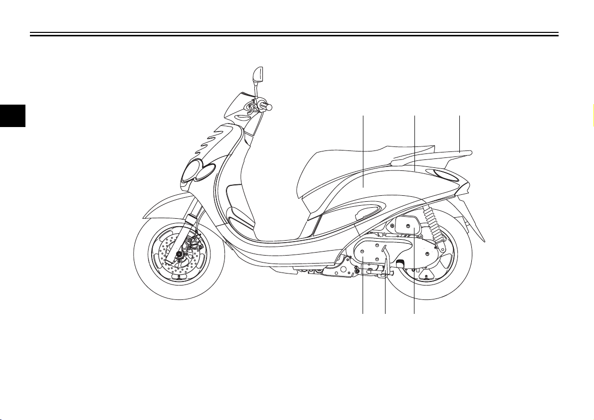
Left view
EAU00026
2
1. Storage compartment (page 3-9)
2. Fuel tank cap (page 3-7)
3. Passenger handle (page 5-2)
1 2 3
65 4
4. Air filter (page 6-15)
5. Centerstand (page 6-23)
6. V-belt case air filter (page 6-15)
2-1
Page 14
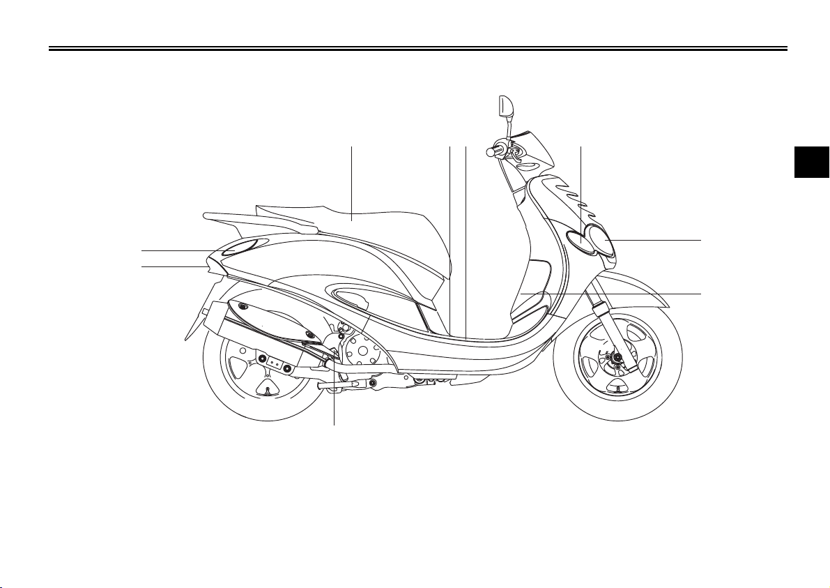
Right view
DESCRIPTION
15
14
7. Seat (page 3-9)
8. Battery (page 6-25)
9. Fuse (page 6-26)
10. Front turn signal (page 6-28)
11. Headlight (page 6-28)
13
7
2-2
8
9
12. Coolant reservoir (page 6-13)
13. Engine oil dipstick (page 6-10)
14. Headlight (page 6-29)
15. Rear turn signal (page 6-28)
10
2
11
12
Page 15
DESCRIPTION
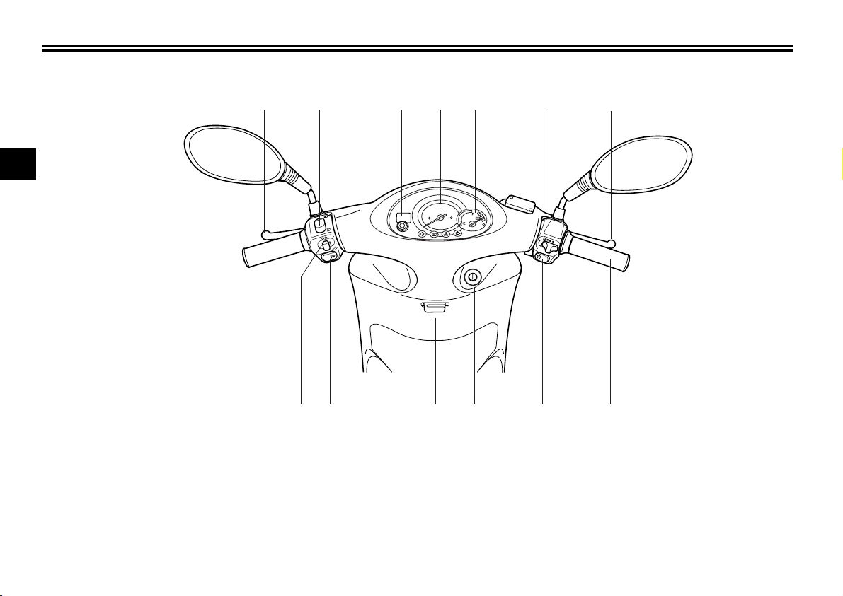
Controls and instruments
2
16 17
18
19
20
21
22
16. Rear brake lever (page 3-7)
17. Dimmer switch (page 3-6)
18. Odometer / Clock (3-4)
19. Speedometer (page 3-4)
20. Battery voltage / Fuel gauge (3-5)
21. Light switch (page 3-6)
22. Front brake lever (page 3-7)
2728
26
25 24
23
23. Throttle grip (page 6-17)
24. Start switch (page 3-6)
25. Main switch / Steering lock (page 3-1)
26. Luggage hook (page 3-10)
27. Horn switch (page 3-6)
28. Turn signal switch (page 3-6)
2-3
Page 16

INSTRUMENT AND CONTROL FUNCTIONS
Main switch / steering lock ............................................................... 3-1
Indicator lights .................................................................................. 3-2
Coolant temperature warning light check......................................... 3-3
Speedometer unit............................................................................. 3-4
Selecting miles or kilometers ........................................................... 3-4
Battery voltage / Fuel gauge ............................................................ 3-5
Clock ................................................................................................ 3-5
Handlebar switches.......................................................................... 3-6
Front brake lever .............................................................................. 3-7
Rear brake lever............................................................................... 3-7
Fuel tank cap.................................................................................... 3-7
Fuel .................................................................................................. 3-8
Catalytic converter ........................................................................... 3-9
Seat..................................................................................................3-9
Storage compartment....................................................................... 3-9
Luggage hook ................................................................................ 3-10
3
Page 17
INSTRUMENT AND CONTROL FUNCTIONS
WARNING
EAU00027
OPEN
PUSH
3
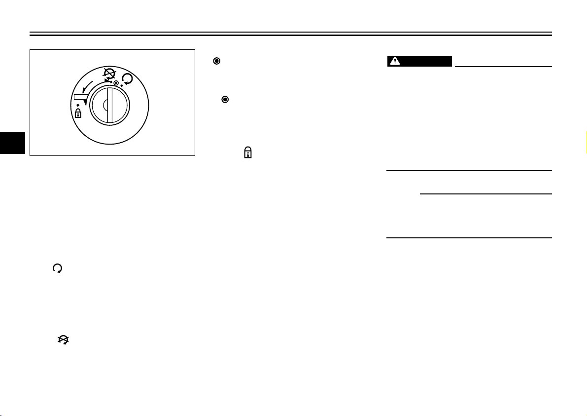
Main switch/steering lock
The main switch/steering lock controls
the ignition and lighting systems, and
is used to lock the steering. The various
positions are described below.
ON “ ”
All electrical systems are supplied with
power, and the engine can be started.
The key cannot be removed.
OFF “ ”
All electrical systems are off. The key
can be removed.
EAU00029
EAU00036
EAU00038
EAUM0038
“ ”
The coolant temperature warning light
should come on, when the key is turned
to “ ”. See page 3-2 for an explanation
of the coolant temperature warning
light.
EAUM0015
LOCK “ ”
The steering is locked, and all electrical
systems are off. The key can be
removed.
To lock the steering
1. Turn the handlebars all the way to
the left or right.
2. Push the key in from the “OFF”
position, and then turn it to “LOCK”
while still pushing it.
3. Remove the key.
To unlock the steering
Push the key into the main switch, and
then turn it to “OFF” while still pushing
it.
EW000016
Never turn the key to “OFF” or
“LOCK” while the scooter is moving,
otherwise the electrical systems will
be switched off, which may result in
loss of control or an accident. Make
sure that the scooter is stopped
before turning the key to “OFF” or
“LOCK”.
NOTE:
Always turn the main switch to “OFF”
or “LOCK” and remove the key when
the scooter is unattended.
3-1
Page 18
TOTAL
1
ZAUM0007
ZAUM0006
1. Turn indicator lights “ , ”
2. High beam indicator light “ ”
3. Coolant temperature warning light “ ”
1 2 3 1
EAU00056
Indicator lights
EAU03125
Turn indicator lights “ , ”
The corresponding indicator flashes
when the turn signal switch is moved
to the left or right.
EAU00064
High beam indicator light “ ”
This indicator light comes on when the
high beam of the headlight is switched
on.
INSTRUMENT AND CONTROL FUNCTIONS
EAU01716
Coolant temperature warning light
“ ”
This warning light comes on when the
engine overheats. When this occurs,
stop the engine immediately and allow
the engine to cool.
CAUTION:
Do not operate the engine if it is
overheated.
EC000002
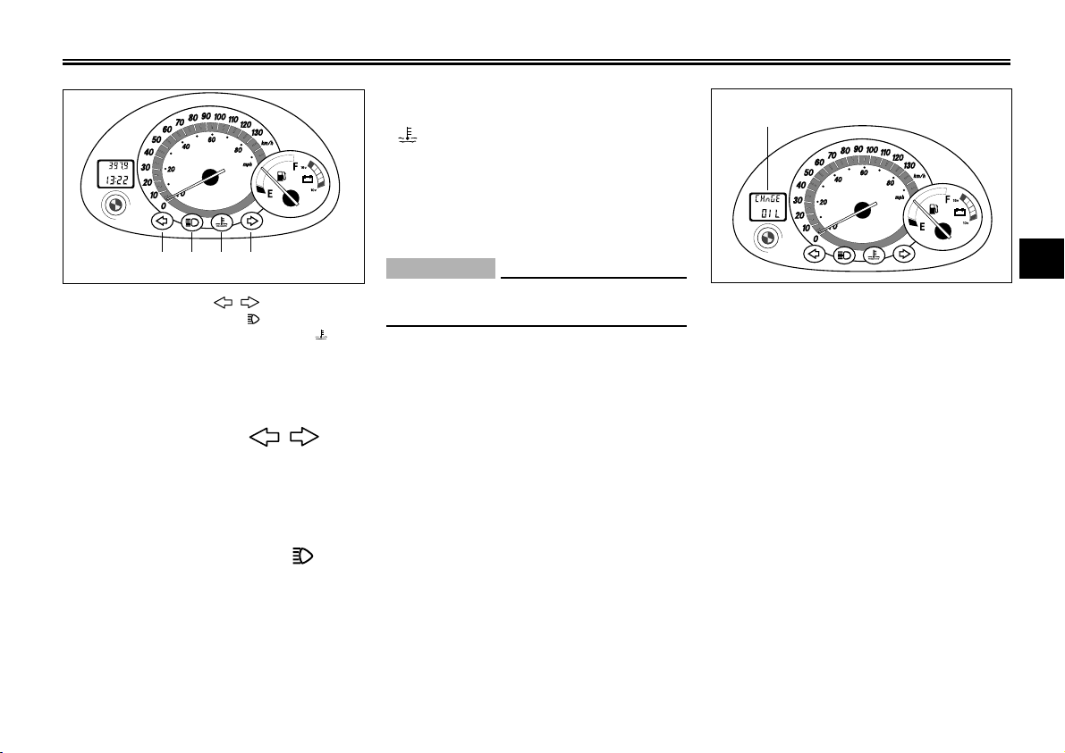
1. Oil change indicator “CHnGE OIL”
Oil change indicator
At the initial 500 km and every 3,000
km thereafter, the message “CHnGE
OIL” appears in the odometer/clock
display to indicate that the engine oil
should be changed. (See page 6-10 for
the resetting procedure.)
3
EAUM0048
3-2
Page 19
INSTRUMENT AND CONTROL FUNCTIONS
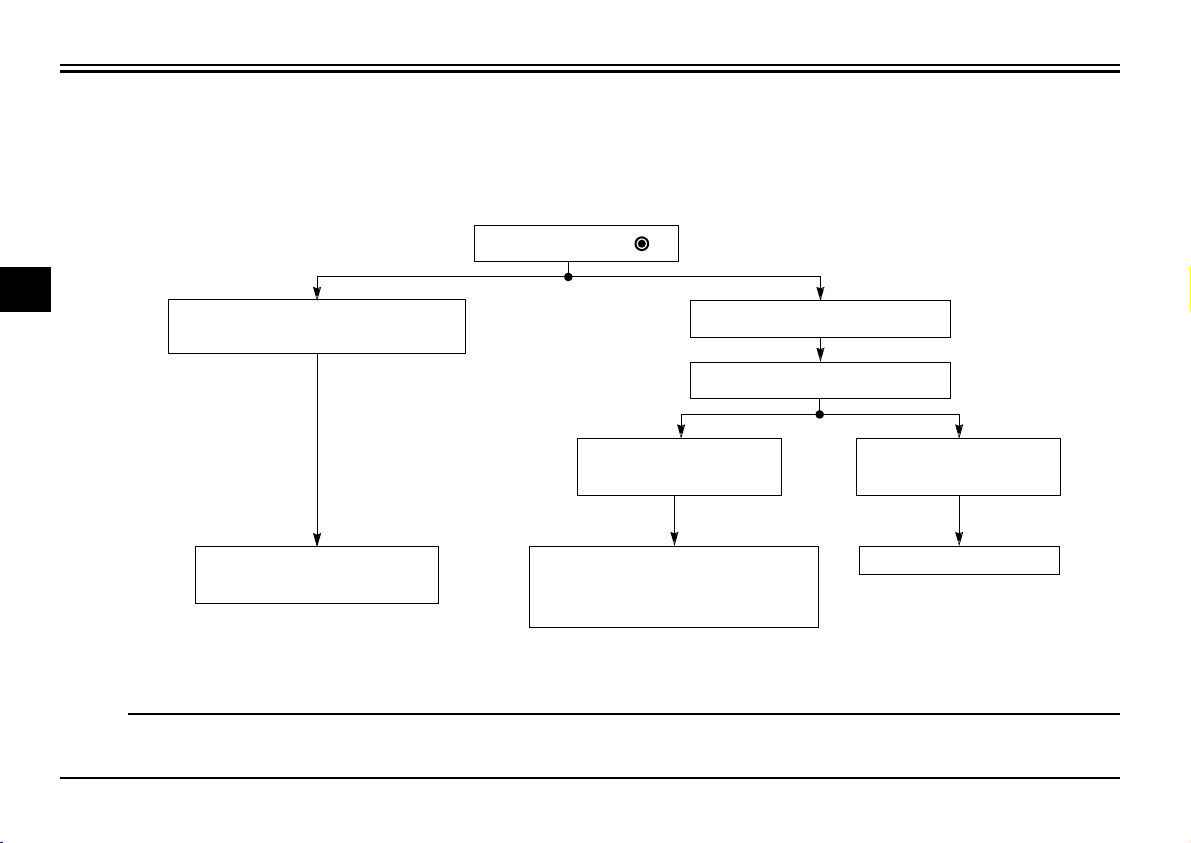
Coolant temperature warning light check
Turn the key to “ ”.
3
The warning light does not come
on. (See the NOTE below.)
EAU01292
The warning light comes on.
Wait a few seconds.
The warning light
does not go off.
Have a Yamaha dealer
check the electrical circuit.
NOTE:
If, after the warning light goes off, the key is turned to “OFF” and then immediately back to “ON”, the warning light may not
come on again, but this does not indicate a malfunction.
See the “Engine overheating”
section on page 6-32 for further
instructions.
3-3
The warning light
goes off.
Go ahead with riding.
Page 20
1
TOTAL
2
3
ZAUM0008
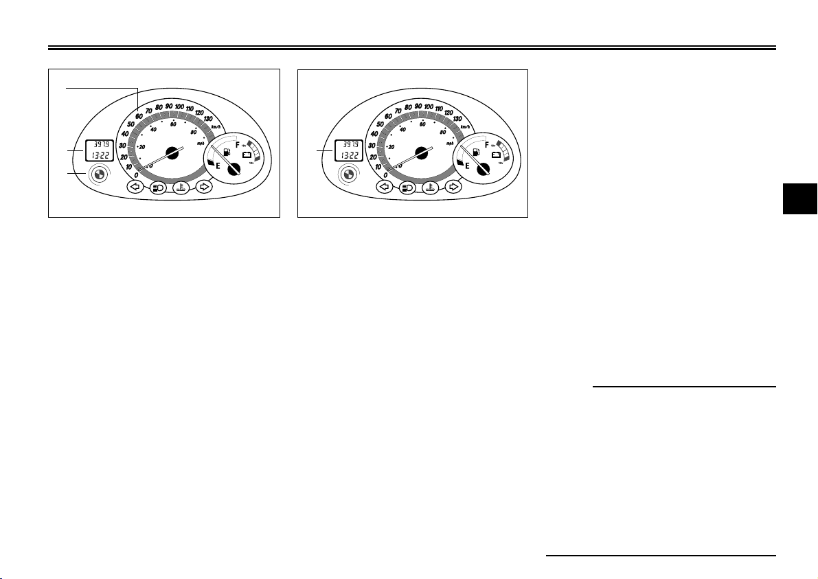
1. Speedometer
2. Odometer
3. “TRIP” button
EAU01586
Speedometer unit
The speedometer unit is equipped with
a speedometer, an odometer and a
tripmeter. The speedometer shows
riding speed. The odometer shows the
total distance traveled. The tripmeter
shows the distance traveled since it
was last set to zero.
Pushing the “TRIP” button switches the
display between the odometer mode
“TOTAL” and the tripmeter mode
“TRIP”. To reset the tripmeter, enter the
“TRIP” mode, and then hold down the
“TRIP” button for at least two seconds.
INSTRUMENT AND CONTROL FUNCTIONS
Setting the odometer/tripmeter
reading mode
The odometer and tripmeter can be set to
TOTAL
1
ZAUM0009
1. Tripmeter
The tripmeter can be used together with
the fuel gauge to estimate the distance
that can be traveled with a full tank of
fuel. This information will enable you
to plan future fuel stops.
3-4
count in either miles or kilometers
according to the following procedure.
1. Turn the key to “ON” while pressing
the “TRIP” button.
2. Release the “TRIP” button when the
display comes on.
3. The current mode appears in the
display: “CONT” (continental) for the
kilometer mode and “EnGL” (English)
for the mile mode.
4. Press the “TRIP” button to switch the
mode.
5. Press the “TRIP” button for two seconds to confirm the setting.
NOTE:
• The odometer/tripmeter reading mode
can be changed any number of times
while the odometer reading is below
10, but it cannot be changed anymore
after the reading has reached 10.
• Switching between the mile and the
kilometer mode does not change or
convert the current odometer/tripmeter
reading.
EAUM0040
3
Page 21
INSTRUMENT AND CONTROL FUNCTIONS
NOTE:
Do not allow the fuel tank to empty itself
completely.
TOTAL
TOTAL
1
2
3
ZAUM0010
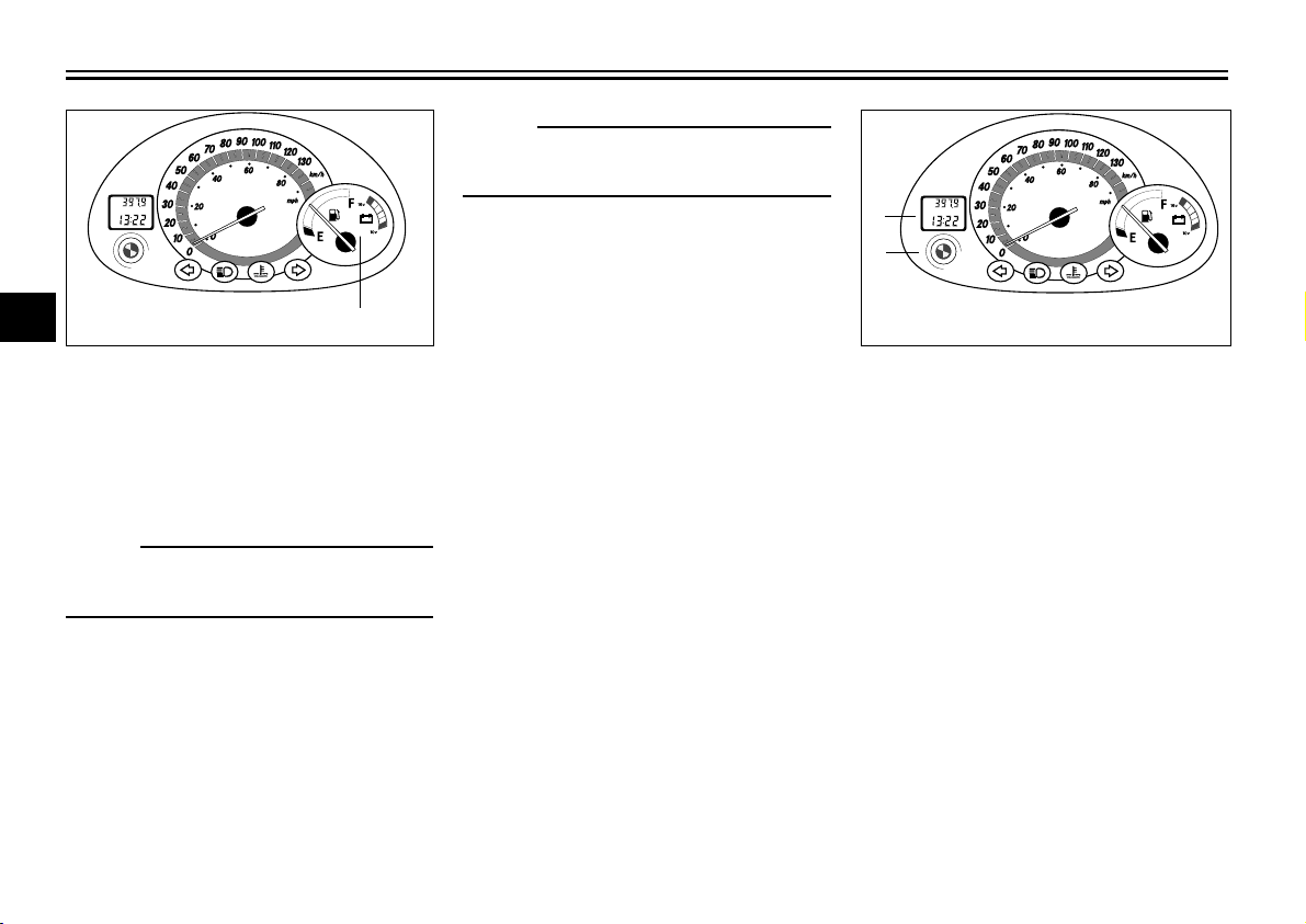
1. Battery voltage / Fuel gauge 1. Clock
1
EAUM0039
Battery voltage/fuel gauge
When the key is turned to “OFF”, the
voltage/fuel gauge indicates the battery
voltage.
NOTE:
If the battery voltage drops to 10 V, have
a Yamaha dealer check the battery.
When the key is turned to “ON”, the voltage/fuel gauge indicates the amount
of fuel in the fuel tank after indicating
the battery voltage for two seconds.
The needle moves towards “E” (empty)
as the fuel level decreases. When the
needle reaches “E”, refuel as soon as
possible.
3-5
ZAUM0012
2. “TRIP” button
EAUM0041
Clock
To set the clock:
1. Turn the key to “ON”.
2. Press the “TRIP” button for two
seconds, and the hour display will
flash.
3. Press the “TRIP” button to set the
hours.
4. Press the “TRIP” button for two
seconds, and the first minute digit
will flash.
5. Press the “TRIP” button to set the
first minute digit.
6. Press the “TRIP” button for two
more seconds, and the second minute digit will flash.
Page 22
1
2
ZAUM0016
INSTRUMENT AND CONTROL FUNCTIONS
7. Press the “TRIP” button to set the
second minute digit.
8. Press the “TRIP” button for two
seconds to set the clock.
ZAUM0015
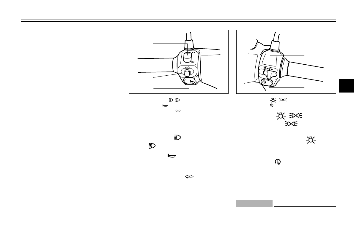
1. Dimmer switch “ , ”
2. Horn switch “ ”
3. Turn signal switch “ ”
Handlebar switches
Dimmer switch
Set this switch to “ ” for the high beam
and to “ ” for the low beam.
Horn switch “ ”
Press this switch to sound the horn.
Turn signal switch “ ”
To signal a right-hand turn, push this
switch to the right. To signal a left-hand
turn, push this switch to the left. When
released, the switch returns to the
center position. To cancel the turn signal lights, push the switch in after it
has returned to the center position.
1
2
3
3-6
EAU00118
EAU00121
EAU00129
EAU00125
1. Light switch “ , ”
2. Start switch “ ”
EAU00132
Light switch “ , ”
Set this switch to
“ ”
to turn on the
auxiliary light, taillight and meter
lighting. Set the switch to
“ ”
to turn
on the headlight also.
EAU00142
Start switch “ ”
Push this switch while applying the front
or rear brake to crank the engine with
the starter.
EC000005
CAUTION:
See page 5-1 for starting instructions prior to starting the engine.
3
Page 23
INSTRUMENT AND CONTROL FUNCTIONS
WARNING
1
ZAUM0019
1
3
ZAUM0017
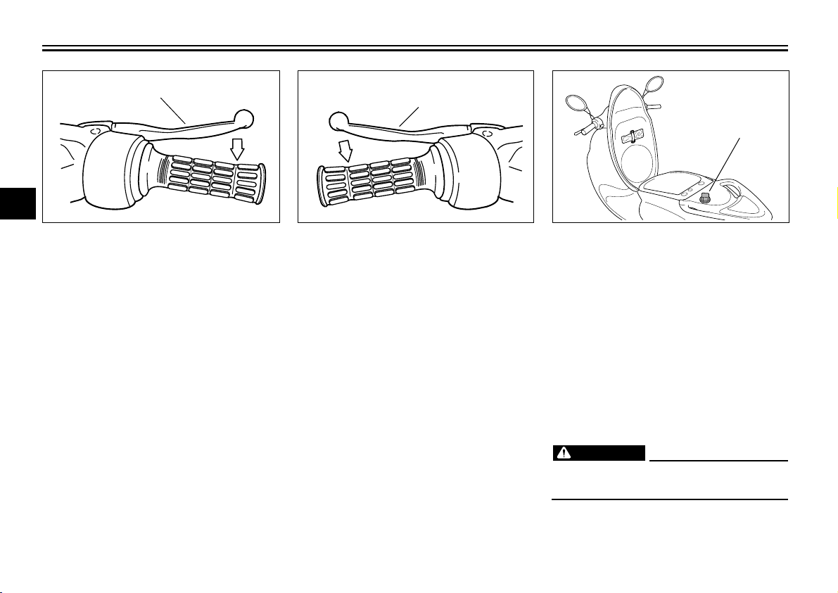
Front brake lever
The front brake lever is located at the
right handlebar grip. To apply the front
brake, pull this lever toward the
handlebar grip.
EAU03035
1
ZAUM0018
1. Rear brake lever
EAU00163
Rear brake lever
The rear brake lever is located on the
left handlebar grip. To apply the rear
brake, pull this lever toward the
handlebar grip.
1. Fuel tank cap1. Front brake lever
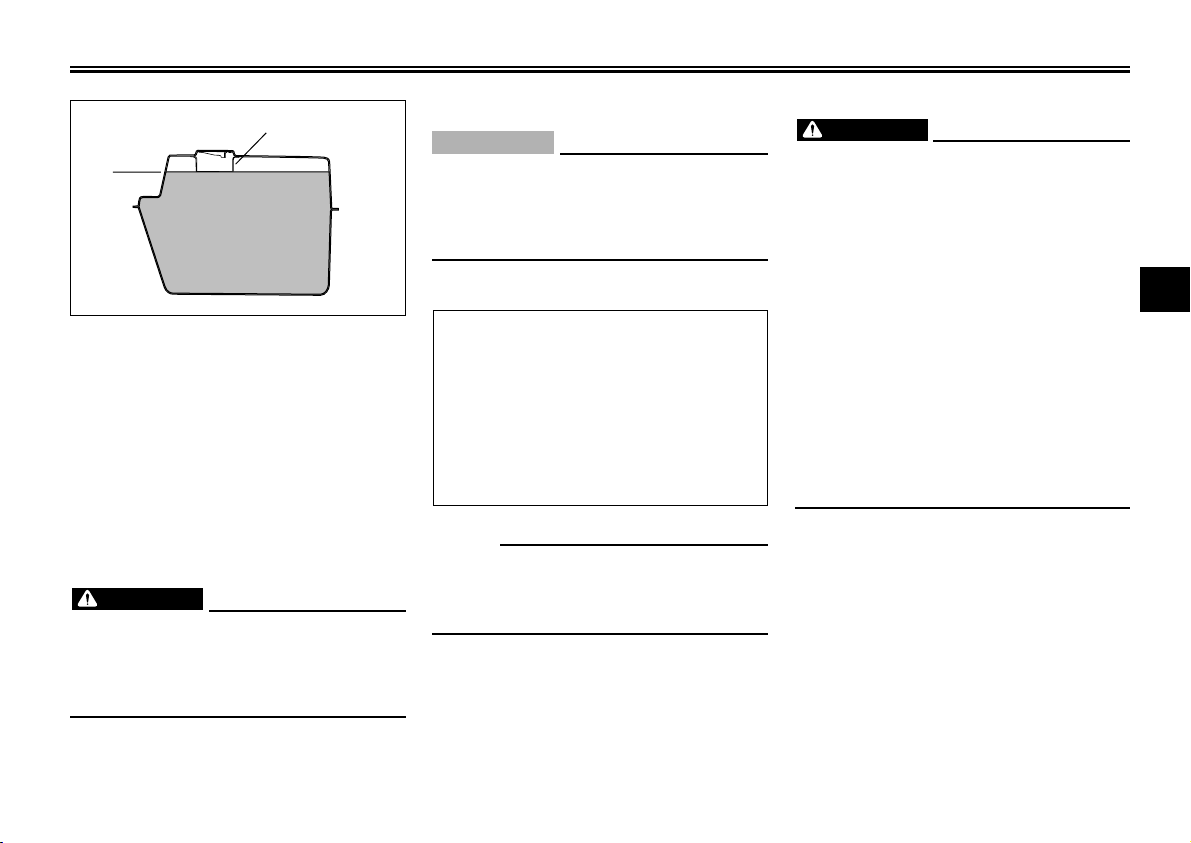
EAU00180
Fuel tank cap
To remove the fuel tank cap
1. Open the seat.
2. Turn the fuel tank cap
counterclockwise and pull it off.
To install the fuel tank cap
1. Insert the fuel tank cap into the tank
opening and turn it clockwise.
2. Close the seat.
EWA00025
Make sure that the fuel tank cap is
properly closed before riding.
3-7
Page 24
INSTRUMENT AND CONTROL FUNCTIONS
1
2
ZAUM0020
1. Filler tube
2. Fuel level
EAU01184
Fuel
Make sure that there is sufficient fuel
in the tank. When refueling, be sure to
insert the pump nozzle into the fuel tank
filler hole and to fill the tank to the
bottom of the filler tube, as shown in
the illustration.
EW000130
WARNING
Do not overfill the fuel tank,
otherwise it may overflow when the
fuel warms up and expands.
Avoid spilling fuel on the hot engine.
EAU00185
EC000008
CAUTION:
Immediately wipe off spilled fuel with
a clean, dry, soft cloth, since fuel
may deteriorate painted surfaces or
plastic parts.
EAU00191
Recommended fuel:
Regular unleaded gasoline with a
research octane number of 91 or
higher
Fuel tank capacity:
Total amount:
10 L
NOTE:
If knocking (or pinging) occurs, use
gasoline of a different brand or with a
higher octane grade.
EWA00008
WARNING
Since gasoline is flammable, the
following precautions must be
observed.
• Stop the engine before refueling.
• Never attempt to refuel the scooter while smoking or near an
open flame.
• Take special care not to spill
gasoline over the engine or
muffler when refueling
immediately after operation.
• Before starting the engine,
quickly wipe off any gasoline
spilled on the engine or muffler.
3
3-8
Page 25
Catalytic converter
WARNING
This scooter is equipped with a catalytic
converter in the exhaust chamber.
WARNING
The exhaust system is hot after
operation. Make sure that the
3
exhaust system has cooled down
before doing any maintenance work.
CAUTION:
The following precautions must be
observed to prevent a fire hazard or
other damages.
• Use only unleaded gasoline. The
use of leaded gasoline will cause
unrepairable damage to the
catalytic converter.
• Never park the scooter near possible fire hazards such as grass
or other materials that easily
burn.
• Do not allow the engine to idle
too long.
EAU01084
EW000128
EC000114
INSTRUMENT AND CONTROL FUNCTIONS
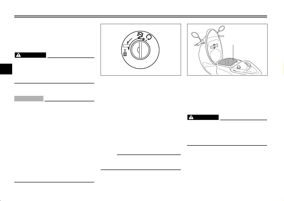
OPEN
PUSH
EAU02978
Seat
To open the seat
1. Insert the key in the lock, and then
turn it as shown.
2. Fold the seat up.
To close the seat
1. Fold the seat down, and then push
it down to lock it in place.
2. Remove the key.
NOTE:
Make sure that the seat is properly
secured before riding.
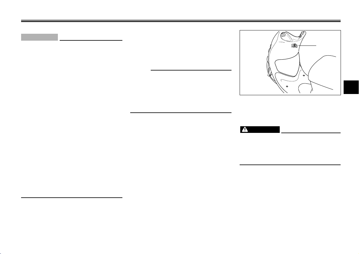
ZAUM0022
1. Storage compartment
Storage compartment
There is a storage compartment under
the seat.
Do not exceed the load limit of 3.0 kg
for the storage compartment.
Do not exceed the maximum load of
310 kg for the vehicle.
1
EAU00268
EWA00005
3-9
Page 26
INSTRUMENT AND CONTROL FUNCTIONS
1
ZAUM0023
EC000010
CAUTION:
Keep the following points in mind
when using the storage
compartment.
• Since the storage compartment
accumulates heat when exposed
to the sun, do not store anything
susceptible to heat inside it.
• To avoid humidity from
spreading through the storage
compartment, wrap wet articles
in a plastic bag before storing
them in the compartment.
• Since the storage compartment
may get wet while the scooter is
being washed, wrap any articles
stored in the compartment in a
plastic bag.
• Do not keep anything valuable or
breakable in the storage
compartment.
To store a helmet in the storage
compartment, place the helmet upsidedown with the front facing forward.
NOTE:
Some helmets cannot be stored in the
storage compartment because of their
size or shape.
Do not leave your scooter unattended
with the seat open.
3
1. Luggage hook
EAUM0043
Luggage hook
EWUM0006
WARNING
• Do not exceed the load limit of
3.0 kg for the luggage hook.
• Do not exceed the maximum
load of 310 kg for the vehicle.
3-10
Page 27

Page 28

PRE-OPERATION CHECKS
Pre-operation check list.................................................................... 4-1
4
Page 29

PRE-OPERATION CHECKS
The condition of a vehicle is the owner’s responsibility. Vital components can start to deteriorate quickly and unexpectedly,
even if the vehicle remains unused (for example, as a result of exposure to the elements). Any damage, fluid leakage or
loss of tire air pressure could have serious consequences. Therefore, it is very important, in addition to a thorough visual
inspection, to check the following points before each ride.
PRE-OPERATION CHECK LIST
ITEM Checks Page
Front brake (disc) • Check operation, free play, fluid level and vehicle for fluid leakage. 3-7/6-19
4
Rear brake (drum) • Check operation, damage and free play. 3-7/6-20
Throttle grip • Check for smooth operation. 6-17
and housing • Adjust / Lubrificate if necessary.
Engine oil • Check engine oil level. 6-10
Final gear oil • Check vehicle for leakage. 6-12
Air filter • Check the condition of dry element 6-14
Wheels/Tires • Check tires pressure, wear and damage. 6-17
Fittings/ • Check all chassis fittings and fasteners. -
Fasteners • Adjust if necessary.
Lights, signals • Check for proper operation. Correct if necessary. 3-6
and switches
Battery • Check the battery fluid level. 6-25
• Fill with DOT #3 or DOT #4 brake fluid if necessary.
• Adjust if necessary.
• Add oil if necessary.
• Add oil if necessary.
• Add with distilled water if necessary.
EAU01114
EAUM0020
4-1
Page 30

PRE-OPERATION CHECKS
NOTE:
Pre-operation checks should be made each time the scooter is used. Such an inspection can be accomplished in a very
short time; and the added safety it assures is more than worth the time involved.
EWUM0002
WARNING
If any item in the pre-operation check is not working properly, have it inspected and repaired before operating the
scooter.
EWUM0003
WARNING
Do not leave a rag which may have been used to clean up gasoline or oil behind any cowling or panel.
4
4-2
Page 31

Page 32

OPERATION AND IMPORTANT RIDING POINTS
Starting a cold engine ...................................................................... 5-1
Starting off ........................................................................................ 5-2
Acceleration and deceleration.......................................................... 5-2
Braking ............................................................................................. 5-2
Engine break-in ................................................................................ 5-3
Parking ............................................................................................. 5-4
5
Page 33

OPERATION AND IMPORTANT RIDING POINTS
CAUTION:
EAU01118
EW000129
WARNING
1. Become thoroughly familiar with
all operating controls and their
functions before riding. Consult
a Yamaha dealer regarding any
control or function that you do
not thoroughly understand.
2. Never start the engine or operate
it in a closed area for any length
of time. Exhaust fumes are
5
poisonous, and inhaling them
can cause loss of consciousness
and death within a short time.
Always make sure that there is
adequate ventilation.
3. For safety, always start the
engine with the centerstand
down.
ZAUM0024
Starting a cold engine
CAUTION:
See page 5-3 for engine break-in instructions prior to operating the
vehicle for the first time.
1. Turn the key to “ON”.
2. Close the throttle completely.
3. Start the engine by pushing the
start switch while applying the front
or rear brake.
EAUM0044
EC000046
EAU00372
NOTE:
If the engine fails to start, release the
start switch, wait a few seconds, and
then try again. Each starting attempt
should be as short as possible to
preserve the battery. Do not crank the
engine more than 10 seconds on any
one attempt.
ECA00045
For maximum engine life, never
accelerate hard when the engine is
cold!
5-1
Page 34

OPERATION AND IMPORTANT RIDING POINTS
ZAUM0027
1
B
A
ZAUM0025
1. Passenger handle
EAUM0027
Starting off
Before starting off, allow the engine to
warm up.
1. While pulling the rear brake lever
with your left hand and holding the
passenger handle with your right
hand, push the scooter off the
centerstand.
2. Sit astride the seat, and then adjust
the rear view mirrors.
3. Switch the turn signal on.
4. Check for oncoming traffic, and
then slowly turn the throttle grip (on
the right) in order to take off.
5. Switch the turn signal off.
ZAUM0026
EAU00434
Acceleration and deceleration
The speed can be adjusted by opening
and closing the throttle. To increase the
speed, turn the throttle grip in direction
A. To reduce the speed, turn the throttle
grip in direction B.
5-2
EAU00435
Braking
1. Close the throttle completely.
2. Apply both front and rear brakes
simultaneously while gradually
increasing the pressure.
5
Page 35

OPERATION AND IMPORTANT RIDING POINTS
CAUTION:
CAUTION:
WARNING
• Avoid braking hard or suddenly
(especially when leaning over to
one side), otherwise the scooter
may skid or overturn.
• Railroad crossings, streetcar
rails, iron plates on road construction sites, and manhole
covers become extremely
slippery when wet. Therefore,
5
slow down when approaching
such areas and cross them with
caution.
• Keep in mind that braking on a
wet road is much more difficult.
• Ride slowly down a hill, as
braking downhill can be very
difficult.
EW000057
EAU00436
Engine break-in
There is never a more important period
in the life of your engine than the period
between 0 and 1,000 km. For this
reason, you should read the following
material carefully.
Since the engine is brand new, do not
put an excessive load on it for the first
1,000 km. The various parts in the
engine wear and polish themselves to
the correct operating clearances.
During this period, prolonged fullthrottle operation or any condition that
might result in engine overheating must
be avoided.
EAUM0051
0 ~ 150 km
Avoid prolonged operation above 1/3
throttle.
After every hour of operation, stop the
engine, and then let it cool for five to
ten minutes.
Vary the engine speed from time to
time. Do not operate the engine at one
set throttle position.
150 ~ 500 km
Avoid prolonged operation above 1/2
throttle.
ECUM0003
After 500 km of operation, the final
gear oil and engine oil must be
changed and the oil strainer cleaned.
500 ~ 1,000 km
Avoid prolonged operation above 3/4
throttle.
1,000 km and beyond
Avoid prolonged full-throttle operation.
Vary the engine speed occasionally.
EC000049
If any engine trouble should occur
during the engine break-in period,
immediately have a Yamaha dealer
check the vehicle.
5-3
Page 36

EAU00461
Parking
When parking, stop the engine, and
then remove the key from the main
switch.
EW000058
WARNING
Since the engine and exhaust
system can become very hot, park
in a place where pedestrians or
children are not likely to touch them.
Do not park on a slope or on soft
ground, otherwise the scooter may
overturn.
EC000062
CAUTION:
Never park in an area where there
are fire hazards such as grass or
other flammable materials.
OPERATION AND IMPORTANT RIDING POINTS
5
5-4
Page 37

Page 38

PERIODIC MAINTENANCE AND MINOR REPAIR
Owner’s tool kit ............................................................
Periodic maintenance and lubrication chart ............ 6-2
Removing and installing cowlings and panels......... 6-5
Panel A ....................................................................6-6
Panel B....................................................................6-6
Cowling C ................................................................ 6-7
Checking the spark plug.......................................... 6-8
Engine oil and oil strainer...................................... 6-10
Final gear oil.......................................................... 6-12
Coolant .................................................................. 6-13
Air filter and the V-belt case air filter elements ...... 6-14
Adjusting the carburetor ........................................ 6-17
Adjusting the throttle cable free play ..................... 6-17
Tires ...................................................................... 6-17
Wheels .................................................................. 6-19
Front brake adjustment ......................................... 6-19
Adjusting the rear brake lever free play ................ 6-20
Checking the front brake pads and rear brake
shoes..................................................................... 6-20
Checking the brake fluid level ............................... 6-21
Changing the brake fkuid ...................................... 6-22
Checking and lubricating the cables ..................... 6-22
Lubricating the front and rear brakes levers.......... 6-23
6-1
Checking and lubricating the centerstand ............. 6-23
Checking the front fork .......................................... 6-23
Checking the steering ........................................... 6-24
Checking the wheel bearings ................................ 6-24
Battery ................................................................... 6-25
Replacing the fuse ................................................ 6-26
Replacing a headlight bulb or a front turn
signal light bulb ..................................................... 6-27
Replacing a rear turn signal light bulb................... 6-28
Replacing taillight bulb .......................................... 6-29
Troubleshooting .................................................... 6-30
Troubleshooting chart ........................................... 6-31
Engine overheating ............................................... 6-32
6
Page 39

PERIODIC MAINTENANCE AND MINOR REPAIR
1
ZAUM0028
EAU00462
Safety is an obligation of the owner.
Periodic inspection, adjustment and
lubrication will keep your vehicle in the
safest and most efficient condition possible. The most important points of inspection, adjustment, and lubrication are
explained on the following pages.
The intervals given in the periodic maintenance and lubrication chart should be
simply considered as a general guide
under normal riding conditions. However,
DEPENDING ON THE WEATHER, TERRAIN, GEOGRAPHICAL LOCATION,
AND INDIVIDUAL USE, THE MAINTE-
6
NANCE INTERVALS MAY NEED TO BE
SHORTENED.
WARNING
If you are not familiar with scooter
maintenance work, have a Yamaha
dealer do it for you.
EAU00464
EW000060
EAU00466
EC000061
CAUTION:
This scooter is designed for use on
paved roads only. If this scooter is
operated in abnormally dusty,
muddy or wet conditions, the air
filter element should be cleaned or
replaced more frequently, otherwise
rapid engine wear may result.
Consult a Yamaha dealer for proper
maintenance intervals.
EW000063
WARNING
Modifications not approved by
Yamaha may cause loss of performance and render the vehicle unsafe
for use. Consult a Yamaha dealer
before attempting any changes.
EW000063
WARNING
Modifications not approved by
Yamaha may cause loss of performance and render the vehicle unsafe
for use. Consult a Yamaha dealer
before attempting any changes.
6-1
1. Owner’s tool kit
EAU00469
Owner’s tool kit
The service information included in this
manual and the tools provided in the
owner’s tool kit are intended to assist you
in the performance of preventive maintenance and minor repairs. However,
additional tools such as a torque wrench
may be necessary to perform certain maintenance work correctly.
NOTE:
If you do not have the tools or experience
required for a particular job, have a
Yamaha dealer perform it for you.
Page 40

PERIODIC MAINTENANCE AND MINOR REPAIR
EAUM0022
Periodic maintenance and lubrication chart
NOTE:
• The annual checks must be performed every year, except if a kilometer-based is performed instead.
• From 30,000 km, repeat the maintenance intervals starting from 6,000 km.
• Items marked with an asterisk should be performed by a Yamaha dealer as they require special tools, data and
technical skills.
N
° Item
1 * Fuel line
2 Spark plug
3 * Valves
4 Air filter
5 V-belt (crankcase) air filter
6 * Battery
7 * Front brake (disc)
8 * Rear brake (drum)
9 * Brake hose
Check and maintenance and lubrication
• Check fuel hoses and vacuum hose for cracks or damage.
• Check condition.
• Clean, regap.
• Replace.
• Check valve clearance.
• Adjust.
• Clean.
• Replace.
• Clean.
• Check electrolyte level and specific gravity.
• Make sure that the breather hose is properly routed.
• Check operation, fluid level and vehicle for fluid leakage.
(See NOTE on page 6-4)
• Replace brake pads.
• Check operation and adjust brake lever freeplay.
• Replace brake shoes.
• Check for cracks or damage.
• Replace.
6-2
ODOMETER READING (X 1,000 KM)
0.5
6
Whenever necessary
Whenever necessary
18 24
12
Every 4 years.
Annual
check
6
Page 41

PERIODIC MAINTENANCE AND MINOR REPAIR
N
° Item
10 * Wheels
11 * Tires
12 * Wheel bearings
13 * Steering bearings
14 Chassis fasteners
15 Centerstand
16 * Front fork
6
17 * Rear shock absorber
assembly
18 * Carburetor
19 * Engine oil
20 * Engine oil filter strainer
21 * Final gear oil
22 * Coolant system
23 V-belt
Check and maintenance and lubrication
• Check runout and for damage.
• Check tread depth and for damage.
• Replace if necessary.
• Check air pressure.
• Correct if necessary.
• Checks bearing for looseness or damage.
• Check bearing play and steering for roughness.
• Lubricate with lithium soap base grease.
• Make sure that all nuts, bolts and screws are properly
tightened.
• Check operation.
• Lubricate.
• Check operation and for oil leakage.
• Check operation and shock absorber for oil leakage.
• Check engine idling speed and starter operation.
• Change.
• Clean.
• Check vehicle for oil leakage
• Change.
• Check coolant level and vehicle for coolant leakage.
• Change.
• Check wear and damage.
• Replace.
ODOMETER READING (X 1,000 KM)
0.5
6
Every 3,000 km
18 24
12
Every 3 year
Every 18,000 km
Annual
check
6-3
Page 42

PERIODIC MAINTENANCE AND MINOR REPAIR
ODOMETER READING (X 1,000 KM)
N
° Item
25
Moving parts and cables
26 * Lights, signals and
switches
Check and maintenance and lubrication
• Lubricate.
• Check operation.
• Adjust headlight beam.
0.5
6
NOTE:
• The air filter needs more frequent service if you are riding in unusually wet or dusty areas.
• Hydraulic brake service
• Regularly check and, if necessary, correct the brake fluid level.
• Every two years replace the brake fluid.
12
18 24
Annual
check
6
6-4
Page 43

PERIODIC MAINTENANCE AND MINOR REPAIR
1
ZAUM0031
1
1
ZAUM0029
Removing and installing
cowlings and panels
The cowlings and panels shown above
6
need to be removed to perform some
of the maintenance jobs described in
this chapter. Refer to this section each
time a cowling or panel needs to be
removed and installed.
ZAUM0030
1. Cover B 1. Cover C1. Cover A
EAU01139
6-5
Page 44

PERIODIC MAINTENANCE AND MINOR REPAIR
11
ZAUM0033
1
1
ZAUM0011
1. Screw
EAU01315
ZAUM0032
Panel A
To remove the panel
Remove the screws, and then take the
panel off.
To install the panel
Place the panel in the original position,
and then install the screws.
6-6
1. Screw
EAU01315
Panel B
To remove the panel
Remove the screws, and then take the
panel off.
To install the panel
Place the panel in the original position,
and then install the screws.
6
Page 45

1
1
ZAUM0014
11
ZAUM0013
ZAUM0034
1. Screw 1. Screw
EAU00482
Cowling C
To remove the cowling
Remove the screws, and then take the
6
cowling off.
To install the cowling
Place the cowling in the original position, and then install the screws.
6-7
Page 46

PERIODIC MAINTENANCE AND MINOR REPAIR
1
1
To check the spark plug
1. Check that the porcelain insulator
around the center electrode of the
spark plug is a medium-to-light tan
(the ideal color when the
motorcycle is ridden normally).
ZAUM0035
1. Spark plug cap 1. Spark plug wrench
EAU01833
Checking the spark plug
The spark plug is an important engine
component, which is easy to check.
ZAUM0036
2. Remove the spark plug as shown,
with the spark plug wrench included
in the owner’s tool kit.
Since heat and deposits will cause any
spark plug to slowly erode, the spark
plug should be removed and checked
in accordance with the periodic maintenance and lubrication chart. In addition, the condition of the spark plug can
reveal the condition of the engine.
To remove the spark plug
1. Remove the spark plug cap.
6-8
NOTE:
If the spark plug shows a distinctly
different color, the engine could be
defective. Do not attempt to diagnose
such problems yourself. Instead, have
a Yamaha dealer check the motorcycle.
2. Check the spark plug for electrode
erosion and excessive carbon or
other deposits, and replace it if
necessary.
6
Page 47

1
ZAUM0037
1. Spark plug gap
Specified spark plug:
CR8E (NGK)
6
PERIODIC MAINTENANCE AND MINOR REPAIR
To install the spark plug
1. Measure the spark plug gap with a
wire thickness gauge and, if
necessary, adjust the gap to
specification.
Spark plug gap:
0.5 ~ 0.7 mm
2. Clean the surface of the spark plug
gasket and its mating surface, and
then wipe off any grime from the
spark plug threads.
3. Install the spark plug with the spark
plug wrench, and then tighten it to
the specified torque.
Tightening torque:
Spark plug:
20 Nm (2.0 m•kg)
NOTE:
If a torque wrench is not available when
installing a spark plug, a good estimate
of the correct torque is 1/4 ~ 1/2 turn
past finger tight. However, the spark
plug should be tightened to the
specified torque as soon as possible.
4. Install the spark plug cap.
6-9
Page 48

PERIODIC MAINTENANCE AND MINOR REPAIR
1
ZAUM0039
1
2
3
ZAUM0038
1. Dipstick
2. Maximum level
3. Minimum level
EAU00513
Engine oil and oil strainer
The engine oil level should be checked
before each ride. In addition, the oil
must be changed and the oil strainer
cleaned at the intervals specified in the
periodic maintenance and lubrication
chart and when the oil change indicator
light comes on.
To check the engine oil level
1. Place the scooter on the
centerstand.
NOTE:
Make sure that the scooter is positioned
straight up when checking the oil level.
A slight tilt to the side can result in a
false reading.
2. Start the engine, warm it up for
several minutes, and then turn it off.
3. Wait a few minutes until the oil
settles, remove the oil filler cap,
wipe the dipstick clean, insert it
back into the oil filler hole (without
screwing it in), and then remove it
again to check the oil level.
NOTE:
The engine oil should be between the
minimum and maximum level marks.
4. If the engine oil is below the minimum level mark, add sufficient oil
of the recommended type to raise
it to the correct level.
5. Insert the dipstick into the oil filler
hole, and then tighten the oil filler
cap.
6-10
1. Engine oil drain plug
To change the engine oil and clean
the oil strainer
1. Start the engine, warm it up for
several minutes, and then turn it off.
2. Place an oil pan under the engine
to collect the used oil.
3. Remove the engine oil filler cap and
drain bolt to drain the oil from the
crankcase.
EC000070
CAUTION:
When removing the engine oil drain
bolt, the O-ring, spring, and oil
strainer will fall out. Take care not to
lose these parts.
6
Page 49

PERIODIC MAIPERIODIC MAINTENANCE AND MINOR REPAIR
CAUTION:
3
2
1
ZAUM0040
1. O-ring
2. Compression spring
3. Strainer
4. Clean the oil strainer with solvent,
and then check it for damage and
6
replace it if necessary.
5. Check the O-ring for damage and
replace it if necessary.
6. Install the oil strainer, spring, O-ring
and engine oil drain bolt, and then
tighten the drain bolt to the
specified torque.
Tightening torque:
Engine oil drain bolt:
32 Nm (3.2 m•kg)
NOTE:
Make sure that the O-ring is properly
seated.
7. Add the specified amount of the
recommended engine oil, and then
install and tighten the oil filler cap.
Recommended engine oil:
See page 8-1.
Oil quantity:
Periodic oil change:
1.2 L
Total amount (dry engine):
1.4 L
8. Start the engine, and then let it idle
for several minutes while checking
it for oil leakage. If oil is leaking,
immediately turn the engine off and
check for the cause.
9. Reset the oil change indicator light
according to the following
procedure.
EC00030
• Do not mix any chemical additives with the oil or use oils of a
higher grade than “CD”. In addition, do not use oils labeled
“ENERGY CONSERVING II” or
higher.
• Make sure that no foreign
material enters the crankcase.
6-11
Page 50

PERIODIC MAINTENANCE AND MINOR REPAIR
1
ZAUM0043
1
TOTAL
1
ZAUM0041
1. “TRIP” button 1. Oil filler bolt 1. Oil drain bolt
To reset the oil change indicator light
1. Push the “TRIP” button while
turning the key to “ON”.
2. Release the reset button, and the
oil change indicator light will go off.
NOTE:
If the engine oil is changed before the
oil change indicator light comes on (i.e.
before the periodic oil change interval
has been reached), the indicator light
must be reset after the oil change for
the next periodic oil change to be
indicated at the correct time. To reset
the oil change indicator light before the
periodic oil change interval has been
reached, follow the above procedure.
ZAUM0042
EAU02961
Final gear oil
The final gear case must be checked
for oil leakage before each ride. If any
leakage is found, have a Yamaha dealer check and repair the scooter. In addition, the final gear oil must be
changed as follows at the intervals
specified in the periodic maintenance
and lubrication chart.
1. Place the scooter on the
centerstand.
NOTE:
Make sure that the scooter is positioned
straight up when checking the oil level.
A slight tilt to the side can result in a
false reading.
6-12
2. Place an oil pan under the final gear
case to collect the used oil.
3. Remove the oil filler bolt and drain
bolt to drain the oil from the final
gear case.
4. Install the final gear oil drain bolt,
and then tighten it to the specified
torque.
Tightening torque:
Final gear oil drain bolt:
22 Nm (2.2 m•kg)
6
Page 51

5. Add the specified amount of the
1
ZAUM0045
recommended final gear oil, and
then install and tighten the oil filler
bolt.
PERIODIC MAINTENANCE AND MINOR REPAIR
Recommended final gear oil:
Engine oil SAE 10W30
(API SE)
Oil quantity:
0.15 L
WARNING
Make sure that no foreign material
6
enters the final gear case.
Make sure that no oil gets on the tire
or wheel.
6. Check the final gear case for oil
leakage. If oil is leaking, check for
the cause.
EW000066
1
2
ZAUM0044
1. Maximum level mark
2. Minimum level mark
EAU01587
Coolant
To check the coolant level
1. Place the scooter on the
centerstand.
NOTE:
• The coolant level must be checked
on a cold engine since the level
varies with engine temperature.
• Make sure that the scooter is
positioned straight up when
checking the coolant level. A slight
tilt to the side can result in a false
reading.
6-13
1. Coolant reservoir cap
2. Remove panel B. (See page 6-6
for cover removal and installation
procedures.)
3. Check the coolant level in the
coolant reservoir.
NOTE:
The coolant should be between the
minimum and maximum level marks.
4. If the coolant is at or below the minimum level mark, open the
reservoir cap, add coolant to the
maximum level mark, and then
close the reservoir cap.
Page 52

PERIODIC MAINTENANCE AND MINOR REPAIR
Coolant reservoir capacity:
0.35 L
5. Install the panel B.
EC000080
CAUTION:
• If coolant is not available, use
distilled water or soft tap water
instead. Do not use hard water
or salt water since it is harmful
to the engine.
• If water has been used instead
of coolant, replace it with coolant
as soon as possible, otherwise
the engine may not be
sufficiently cooled and the
cooling system will not be
protected against frost and corrosion.
• If water has been added to the
coolant, have a Yamaha dealer
check the antifreeze content of
the coolant as soon as possible,
otherwise the effectiveness of
the coolant will be reduced.
EW000067
WARNING
Never attempt to remove the radiator
cap when the engine is hot.
NOTE:
The radiator fan is automatically
switched on or off according to the
coolant temperature in the radiator. If
the engine overheats, see page 6-32
for further instructions.
6-14
EAUM0034
Air filter and V-belt case air
filter elements
The air filter and the V-belt case air filter
elements should be cleaned at the
intervals specified in the periodic maintenance and lubrication chart. Clean
both filter elements more frequently if
you are riding in unusually wet or dusty
areas.
6
Page 53

PERIODIC MAINTENANCE AND MINOR REPAIR
1
2
2
ZAUM0048
1
2
ZAUM0046
1. Air filter case cover
2. Screws
Cleaning the air filter element
1. Place the scooter on the
centerstand.
2. Remove the air filter case cover by
6
removing the screws.
3. Pull the air filter element out.
1
ZAUM0047
1. Air filter element
4. Lightly tap the air filter element to
remove most of the dust and dirt,
and then blow the remaining dirt out
with compressed air.
5. Check the air filter element for
damage and replace it if necessary.
6. Insert the air filter element into the
air filter case.
7. Install the air filter case cover by
installing the screws.
1. V-belt case air filter cover
2. Screws
Cleaning the V-belt case air filter
element
1. Remove the V-belt case air filter
cover by removing the screws.
6-15
Page 54

PERIODIC MAINTENANCE AND MINOR REPAIR
1
ZAUM0049
1. V-belt case air filter element
ZAUM0050
EC000092
CAUTION:
• Make sure that each filter
element is properly seated in its
case.
• The engine should never be
operated without the filter
elements installed, otherwise the
piston(s) and/or cylinder(s) may
become excessively worn.
2. Remove the air filter element, and
then blow out the dirt with
compressed air as shown.
3. Check the air filter element for
damage and replace it if necessary.
4. Install the air filter element with the
colored side facing outward.
5. Install the V-belt case air filter
element cover by installing the
screws.
6-16
6
Page 55

Adjusting the carburetor
WARNING
0
1
2
3
4
ZAUM0053
The carburetor is an important part of
the engine and requires very
sophisticated adjustment. Therefore, all
carburetor adjustments should be left
to a Yamaha dealer, who has the
necessary professional knowledge and
experience.
6
EAU00631
PERIODIC MAINTENANCE AND MINOR REPAIR
1
ZAUM0051
1. Throttle cable free play
EAU00635
Adjusting the throttle cable
free play
The throttle cable free play should
measure 1.5 ~ 3.0 mm at the throttle
grip. Periodically check the throttle
cable free play and, if necessary, have
a Yamaha dealer adjust it.
Tires
To maximize the performance,
durability, and safe operation of your
scooter, note the following points
regarding the specified tires.
Tire air pressure
The tire air pressure should be checked
and, if necessary, adjusted before each
ride.
EAU00675
EW000082
The tire air pressure must be
checked and adjusted on cold tires
(i.e., when the temperature of the tires equals the ambient temperature).
The tire air pressure must be
6-17
Page 56

PERIODIC MAINTENANCE AND MINOR REPAIR
CE-08E
Minimum tire tread depth
(front and rear)
0,8 mm
adjusted in accordance with the
riding speed and with the total
weight of rider, passenger, cargo,
and accessories approved for this
model.
CE-05E
Load*
Up to 90 kg*:
90 kg ~
Maximum
* Total weight of rider, passenger, cargo and
accessories
CE-07E
Maximum load*
* Total weight of rider, passenger, cargo and
accessories.
WARNING
Because loading has an enormous
impact on the handling, braking, performance and safety characteristics
of your scooter, you should keep the
following precautions in mind.
Tire air pressure (measured on cold tires)
2
2
Rear
200 kPa
2,0 kg/cm
2,0 bar
220 kPa
2,2 kg/cm
2,2 bar
310 kg
EW000077
Front
180 kPa
1,8 kg/cm
1,8 bar
200 kPa
2,0 kg/cm
2,0 bar
NEVER OVERLOAD THE SCOOTER!
Operation of an overloaded scooter
may result in tire damage, loss of
control, or severe injury. Make sure
that the total weight of rider, cargo,
and accessories does not exceed
the specified maximum load for the
vehicle.
Do not carry along loosely packed
2
items, which can shift during a ride.
Securely pack the heaviest items
close to the center of the scooter and
2
distribute the weight evenly on both
sides.
Adjust the suspension and tire air
pressure with regard to the load.
Check the tire condition and air pressure before each ride.
6-18
1
2
ZAUM0054
1. Tread depth
2. Side wall
Tire inspection
The tires must be checked before each
ride. If the center tread depth reaches
the specified limit, if the tire has a nail
or glass fragments in it, or if the sidewall
is cracked, have a Yamaha dealer replace the tire immediately.
NOTE:
The tire tread depth limits may differ
from country to country. Always comply
with the local regulations.
6
Page 57

PERIODIC MAINTENANCE AND MINOR REPAIR
WARNING
ZAUM0055
WARNING
Have a Yamaha dealer replace
excessively worn tires. Besides
being illegal, operating the scooter
with excessively worn tires
decreases riding stability and can
lead to loss of control.
The replacement of all wheel- and
brake-related parts, including the tires, should be left to a Yamaha dealer, who has the necessary
professional knowledge and
experience.
6
Tire information
This scooter is equipped with tubeless
tires.
CE-10G
Front and rear
Manufacturer Size Type
HUTCHINSON 120/70-12
PLANET
EW000079
EAU00687
Wheels
To maximize the performance,
durability, and safe operation of your
scooter, note the following points
regarding the specified wheels.
• The wheel rims should be checked
for cracks, bends or warpage
before each ride. If any damage is
found, have a Yamaha dealer replace the wheel. Do not attempt
even the smallest repair to the
wheel. A deformed or cracked
wheel must be replaced.
• The wheel should be balanced
whenever either the tire or wheel
has been changed or replaced. An
unbalanced wheel can result in
poor performance, adverse
handling characteristics, and a
shortened tire life.
• Ride at moderate speeds after
changing a tire since the tire surface must first be «broken in» for it
to develop its optimal
characteristics.
Front
EAUM0006
Front brake adjustment
The front brake lever should have a free
play of 10 ~ 20 mm at the lever end. If
not, ask a Yamaha dealer to adjust it.
EW000100
An incorrect brake lever free play
indicates a hazardous condition in
the brake system. Do not operate the
scooter until the brake system has
been checked or repaired by a
Yamaha dealer.
6-19
Page 58

PERIODIC MAINTENANCE AND MINOR REPAIR
Rear
ZAUM0056
EAUM0028
Adjusting the rear brake lever
free play
The rear brake lever free play should
measure 10 ~ 20 mm as shown.
Periodically check the rear brake lever
free play and, if necessary, adjust it as
follows.
B
ZAUM0057
To increase the rear brake lever free play,
turn the adjusting nut at the brake shoe
plate in direction A. To decrease the rear
brake lever free play, turn the adjusting
nut in direction B.
WARNING
If proper adjustment cannot be
obtained as described, have a
Yamaha dealer make this
adjustment.
A
EW000101
EAU00720
Checking the front brake pads
and rear brake shoes
The front brake pads and the rear brake
shoes must be checked for wear at the
intervals specified in the periodic maintenance and lubrication chart.
6
6-20
Page 59

PERIODIC MAINTENANCE AND MINOR REPAIR
1
ZAUM0060
1
1
ZAUM0058
1. Wear limit
Front brake pads
Check each front brake pad for damage
and measure the lining thickness. If a
6
brake pad is damaged or if the lining
thickness is less than 2 mm, have a
Yamaha dealer replace the brake pads
as a set.
EAU01436
ZAUM0059
1. Wear indicator
2. Wear limit
EAU00727
Rear brake shoes
The rear brake is provided with a wear
indicator, which allows you to check the
brake shoe wear without having to
disassemble the brake. To check the
brake shoe wear, check the position of
the wear indicator while applying the
brake. If a brake shoe has worn to the
point that the wear indicator reaches
the wear limit line, have a Yamaha dealer replace the brake shoes as a set.
6-21
2
1. Minimum level
EAU00731
Checking the brake fluid level
Insufficient brake fluid may allow air to
enter the brake system, possibly causing
it to become ineffective.
Before riding, check that the brake fluid is
above the minimum level mark and
replenish if necessary. A low brake fluid
level may indicate worn brake pads and/
or brake system leakage. If the brake level
is low, be sure to check the brake pads
for wear and the brake system for
leakage.
Observe these precautions:
• When checking the fluid level, make
sure that the top of the master cylinder
is level by turning the handlebars.
Page 60

PERIODIC MAINTENANCE AND MINOR REPAIR
WARNING
• Use only the recommended quality
brake fluid, otherwise the rubber
seals may deteriorate, causing
leakage and poor braking performance.
Recommended brake fluid:
DOT #3 or DOT #4
• Refill with the same type of brake
fluid. Mixing fluids may result in a
harmful chemical reaction and lead
to poor braking performance.
• Be careful that water does not enter the master cylinder when
refilling. Water will significantly
lower the boiling point of the fluid
and may result in vapor lock.
• Brake fluid may deteriorate painted
surfaces or plastic parts. Always
clean up spilled fluid immediately.
• As the brake pads wear, it is normal for the brake fluid level to
gradually go down. However, if the
brake fluid level goes down
suddenly, have a Yamaha dealer
check the cause.
EAUM0008
Changing the brake fluid
Have a Yamaha dealer change the
brake fluid at the intervals specified in
the periodic maintenance and
lubrication chart. In addition, have the
brake hose replaced at the intervals
listed below or whenever they are
damaged or leaking.
Brake hose: Replace every four years.
6-22
EAU02962
Checking and lubricating the
cables
The operation of all control cables and
the condition of the cables should be
checked before each ride, and the cables
and cable ends should be lubricated if
necessary. If a cable is damaged or does
not move smoothly, have a Yamaha dealer check or replace it.
Recommended lubricant:
Engine oil
EW000112
Damage to the outer sheath may
interfere with proper cable operation
and will cause the inner cable to rust.
Replace a damaged cable as soon
as possible to prevent unsafe conditions.
6
Page 61

ZAUM0061
WARNING
PERIODIC MAINTENANCE AND MINOR REPAIR
EAU02939
Checking the front fork
The condition and operation of the front
fork must be checked as follows at the
intervals specified in the periodic maintenance and lubrication chart.
To check the condition
ZAUM0062
EW000115
Lubricating the front and rear
brake levers
The pivoting points of the front and rear
6
brake levers must be lubricated at the
intervals specified in the periodic maintenance and lubrication chart.
Recommended lubricant:
Engine oil
EAU00781
EAUM0013
Checking and lubricating the
centerstand
The operation of the centerstand
should be checked before each ride,
and the pivots and metal-to-metal contact surfaces should be lubricated if
necessary.
EW000114
WARNING
If the centerstand does not move up
and down smoothly, have a Yamaha
dealer check or repair it.
Recommended lubricant:
Lithium-soap-based grease
(all-purpose grease)
6-23
Securely support the scooter so that
there is no danger of it falling over.
Check the inner tubes for scratches,
damage and excessive oil leakage.
Page 62

PERIODIC MAINTENANCE AND MINOR REPAIR
To check the operation
1. Place the scooter on a level surface and hold it in an upright position.
2. While applying the front brake,
push down hard on the handlebars
several times to check if the front
fork compresses and rebounds
smoothly.
EC000098
CAUTION:
If any damage is found or the front
fork does not operate smoothly,
have a Yamaha dealer check or
repair it.
EAU00794
Checking the steering
Worn or loose steering bearings may
cause danger. Therefore, the operation
of the steering must be checked as
follows at the intervals specified in the
periodic maintenance and lubrication
chart.
1. Place a stand under the engine to
raise the front wheel off the ground.
EW000115
WARNING
Securely support the scooter so that
there is no danger of it falling over.
2. Hold the lower ends of the front fork
legs and try to move them forward
and backward. If any free play can
be felt, have a Yamaha dealer
check or repair the steering.
EAU01144
Checking the wheel bearings
The front and rear wheel bearings must
be checked at the intervals specified in
the periodic maintenance and
lubrication chart. If there is play in the
wheel hub or if the wheel does not turn
smoothly, have a Yamaha dealer check
the wheel bearings.
6
6-24
Page 63

PERIODIC MAINTENANCE AND MINOR REPAIR
WARNING
Battery
A poorly maintained battery will corrode
and discharge quickly. The electrolyte
level, battery lead connections and
breather hose routing should be
checked before each ride and at the
intervals specified in the periodic maintenance and lubrication chart.
6
EAUM0049
UPPER
+
1
ZAUM0063
1. Battery
LOWER
To check the electrolyte level
1. Place the scooter on a level surface and hold it in an upright position.
NOTE:
Make sure that the scooter is positioned
straight up when checking the
electrolyte level.
2. Remove panel A. (See page 6-6 for
panel removal and installation
procedures.)
3. Check the electrolyte level in the
battery.
NOTE:
The electrolyte should be between the
minimum and maximum level marks.
4. If the electrolyte is at or below the
minimum level mark, add distilled
water to raise it to the maximum
level mark.
EW000116
Electrolyte is poisonous and
dangerous since it contains sulfuric
acid, which causes severe burns.
Avoid any contact with skin, eyes or
clothing and always shield your eyes
when working near batteries. In case
of contact, administer the following
FIRST AID.
EXTERNAL: Flush with plenty of
water.
INTERNAL: Drink large quantities of
water or milk and immediately call a
physician.
EYES: Flush with water for 15 minutes and seek prompt medical attention.
6-25
Page 64

PERIODIC MAINTENANCE AND MINOR REPAIR
1
2
ZAUM0064
Batteries produce explosive
hydrogen gas. Therefore, keep
sparks, flames, cigarettes, etc., away
from the battery and provide
sufficient ventilation when charging
it in an enclosed space.
KEEP THIS AND ALL BATTERIES
OUT OF THE REACH OF CHILDREN.
CAUTION:
Use only distilled water, as tap water
contains minerals that are harmful
to the battery.
5. Check and, if necessary, tighten the
battery lead connections and correct the breather hose routing.
EC000100
To store the battery
1. If the scooter will not be used for
more than one month, remove the
battery, fully charge it, and then
place it in a cool, dry place.
2. If the battery will be stored for more
than two months, check the specific
gravity of the electrolyte at least
once a month and fully charge the
battery whenever necessary.
3. Fully charge the battery before installation.
4. After installation, make sure that the
battery leads are properly
connected to the battery terminals
and that the breather hose is
properly routed, in good condition,
and not obstructed.
EC000099
CAUTION:
If the breather hose is positioned in
such a way that the frame is exposed
to electrolyte or gas expelled from
the battery, the frame could suffer
structural and external damages.
6-26
1. Main fuse
2. Fan fuse
EAUM0050
Replacing the fuse
The fuse holder is located behind panel A. (See page 6-6 for panel removal
and installation procedures.)
If the fuse is blown, replace it as follows.
1. Turn the key to “OFF” and turn off
all electrical circuits.
2. Remove the blown fuse, and then
install a new fuse of the specified
amperage.
Specified fuse:
Main fuse:
20 A
Fan fuse:
7.5 A
6
Page 65

EC000103
WARNING
CAUTION:
Do not use a fuse of a higher
amperage rating than recommended
to avoid causing extensive damage
to the electrical system and possibly
a fire.
PERIODIC MAINTENANCE AND MINOR REPAIR
1
1
1
1
3. Turn the key to “ON” and turn on
the electrical circuits to check if the
devices operate.
4. If the fuse immediately blows again,
have a Yamaha dealer check the
electrical system.
6
5. Install the panel.
ZAUM0065
2. Headlight connector
2
EAUM0035
Replacing a headlight bulb or
a front turn signal light bulb
Replacing a headlight bulb
1. Remove cowling C (See page 6-7
for cowling removal and installation
procedures).
2. Remove the headlight connector.
3. Remove the headlight bulb holder
by turning it 1/4 turn
counterclockwise.
4. Remove the defective bulb.
6-27
ZAUM0066
1. Bulb1. Bulb holder
EW000119
Headlight bulbs get very hot.
Therefore, keep flammable products
away from a lit headlight bulb, and
do not touch the bulb until it has
cooled down.
5. Place a new bulb into position, and
then secure it with the bulb holder.
Page 66

PERIODIC MAINTENANCE AND MINOR REPAIR
1
ZAUM0068
6. Connect the headlight connector
and install the cowling C.
EC000105
CAUTION:
Do not touch the glass part of the
headlight bulb to keep it free from
oil, otherwise the transparency of
the glass, the luminosity of the bulb,
and the bulb life will be adversely
affected. Thoroughly clean off any
dirt and fingerprints on the headlight
bulb using a cloth moistened with
alcohol or thinner.
ZAUM0067
1. Bulb
Replacing a front turn signal light
bulb
1. Remove cowling C (See page 6-7
2. Remove the headlight connector.
3. Remove the socket (together with
4. Remove the defective bulb.
5. Place a new bulb into position.
6. Install the socket (together with the
7. Connect the headlight connector
11
for cowling removal and installation
procedures).
the turn signal light bulb) by turning
it counterclockwise.
bulb) by turning it clockwise.
and install the cowling C.
1. Bulb
EAUM0036
Replacing a rear turn signal
light bulb
1. Remove the turn light signal unit by
removing the screw.
2. Remove the socket (together with
the turn signal light bulb) by turning
it counterclockwise.
3. Remove the defective bulb by
pulling it outward and turning it
counterclockwise.
4. Insert a new bulb into the socket.
5. Install the socket (together with the
bulb) by turning it clockwise.
6. Install the turn signal light unit by
installing the screw.
6
6-28
Page 67

1
ZAUM0069
1. Bulb
Replacing taillight bulb
1. Remove the taillight by removing
the screws.
6
2. Remove the taillight bulb holder by
turning it 1/4 turn counterclockwise.
3. Remove the defective bulb.
4. Place a new bulb into position, and
then secure it with the bulb holder.
5. Place the taillight and then install
the screw.
PERIODIC MAINTENANCE AND MINOR REPAIR
EAUM0037
6-29
Page 68

PERIODIC MAINTENANCE AND MINOR REPAIR
EAU01008
Troubleshooting
Although Yamaha scooters receive a
thorough inspection before shipment
from the factory, trouble may occur
during operation. Any problem in the
fuel, compression, or ignition systems,
for example, can cause poor starting
and loss of power.
The following troubleshooting chart
represents a quick and easy procedure
for checking these vital systems
yourself. However, should your scooter require any repair, take it to a
Yamaha dealer, whose skilled
technicians have the necessary tools,
experience, and know-how to service
the scooter properly.
Use only genuine Yamaha replacement
parts. Imitation parts may look like
Yamaha parts, but they are often
inferior, have a shorter service life and
can lead to expensive repair bills.
6
6-30
Page 69

PERIODIC MAINTENANCE AND MINOR REPAIR
Troubleshooting chart
Starting problems or poor engine performance
WARNING
Keep away open flames and do not smoke while checking or working on the fuel system.
EAU01596
EW000125
6
1. Fuel
Check if there is fuel
in the tank.
2. Compression
Use electric starter.
3. Ignition
Remove spark plug
and check electrode.
4. Battery
Use electric
starter.
Enough fuel.
No fuel.
There is compression.
No compression.
Wet.
Dry.
Engine turns over
quickly.
Engine turns over
slowly.
Go to compression check.
Supply fuel.
Go to inition check.
Ask Yamaha dealer to inspect.
Wipe clean with dry cloth and correct spark plug
gap or replace spark plug.
Ask a Yamaha dealer to inspect.
Battery good.
Check connections
or recharge.
Engine doesn't start, go to
compression check.
Engine doesn't start, ask a Yamaha dealer to inspect.
6-31
Open throttle half-way and start the
engine.
Engine doesn't start, go to battery check.
Page 70

PERIODIC MAINTENANCE AND MINOR REPAIR
Engine overheating
EW000070
WARNING
Do not remove the radiator cap when the engine and radiator are hot. Scalding hot fluid and steam may be blown
out under pressure, which could cause serious injury. Be sure to wait until the engine has cooled.
After removing the radiator cap retaining bolt, place a thick rag, like a towel, over the radiator cap, and then slowly
rotate the cap counterclockwise to the detent to allow any residual pressure to escape. When the hissing sound
has stopped, press down on the cap while turning it counterclockwise, and then remove the cap.
Ask a Yamaha dealer to check and
repair the coolant system.
Add coolant
(see NOTE).
Wait for the engine to
be cold.
Check the coolant level in the coolant
reservoir and/or in the radiator.
The level is low:
check for the
coolant leakage.
Level is good.
Leakage.
No leakage.
Start the engine. If the engine get warm again, ask a
Yamaha dealer to check and repair the coolant system.
6
NOTE:
If coolant is not available, tap water can be temporarily used instead, provided that it is changed to the recommended
coolant as soon as possible.
6-32
Page 71

Page 72

SCOOTER CARE AND STORAGE
Care ................................................................................................. 7-1
Storage............................................................................................. 7-3
7
Page 73

SCOOTER CARE AND STORAGE
CAUTION:
EAU01522
Care
While the open design of a scooter
reveals the attractiveness of the
technology, it also makes it more
vulnerable. Rust and corrosion can
develop even if high-quality
components are used. A rusty exhaust
pipe may go unnoticed on a car,
however, it detracts from the overall
appearance of a scooter. Frequent and
proper care does not only comply with
the terms of the warranty, but it will also
keep your scooter looking good, extend
its life and optimize its performance.
7
Before cleaning
1. Cover the muffler outlet with a plastic bag.
2. Make sure that all caps and covers
as well as all electrical couplers and
connectors, including the spark
plug cap, are tightly installed.
3. Remove extremely stubborn dirt,
like oil burnt onto the crankcase,
with a degreasing agent and a
brush, but never apply such
products onto seals, gaskets and
wheel axles. Always rinse the dirt
and degreaser off with water.
Cleaning
After normal use
Remove dirt with warm water, a mild
detergent, and a soft, clean sponge,
and then rinse thoroughly with clean
water. Use a toothbrush or bottlebrush
for hard-to-reach areas. Stubborn dirt
and insects will come off more easily if
the area is covered with a wet cloth for
a few minutes before cleaning.
ECA00011
• Avoid using strong acidic wheel
cleaners, especially on spoked
wheels. If such products are
used on hard-to-remove dirt, do
not leave the cleaner on the
affected area any longer than
instructed. Also, thoroughly
rinse the area off with water,
immediately dry it, and then
apply a corrosion protection
spray.
• Improper cleaning can damage
windshields, cowlings, panels
and other plastic parts. Use only
7-1
Page 74

SCOOTER CARE AND STORAGE
a soft, clean cloth or sponge with
mild detergent and water to clean
plastic.
• Do not use any harsh chemical
products on plastic parts. Be
sure to avoid using cloths or
sponges which have been in
contact with strong or abrasive
cleaning products, solvent or
thinner, fuel (gasoline), rust
removers or inhibitors, brake
fluid, antifreeze or electrolyte.
• Do not use high-pressure
washers or steam-jet cleaners
since they cause water seepage
and deterioration in the following
areas: seals (of wheel and
swingarm bearings, fork and
brakes), electric components
(couplers, connectors, instruments, switches and lights),
breather hoses and vents.
• For scooters equipped with a
windshield: Do not use strong
cleaners or hard sponges as
they will cause dulling or
scratching. Some cleaning
compounds for plastic may leave
scratches on the windshield.
Test the product on a small
hidden part of the windshield to
make sure that it does not leave
any marks. If the windshield is
scratched, use a quality plastic
polishing compound after
washing.
After riding in the rain, near the sea or
on salt-sprayed roads
Since sea salt or salt sprayed on the
roads during winter are extremely corrosive in combination with water, carry
out the following steps after each ride
in the rain, near the sea or on saltsprayed roads.
NOTE:
Salt sprayed on roads in the winter may
remain well into spring.
1. Clean the scooter with cold water
and a mild detergent after the
engine has cooled down.
7-2
ECA00012
CAUTION:
Do not use warm water since it
increases the corrosive action of the
salt.
2. Apply a corrosion protection spray
on all metal, including chrome- and
nickel-plated, surfaces to prevent
corrosion.
7
Page 75

SCOOTER CARE AND STORAGE
CAUTION:
After cleaning
1. Dry the scooter with a chamois or
an absorbing cloth.
2. Use a chrome polish to shine
chrome, aluminum and stainlesssteel parts, including the exhaust
system. (Even the thermally
induced discoloring of stainlesssteel exhaust systems can be
removed through polishing.)
3. To prevent corrosion, it is
recommended to apply a corrosion
protection spray on all metal,
including chrome- and nickelplated, surfaces.
4. Use spray oil as a universal cleaner
7
to remove any remaining dirt.
5. Touch up minor paint damage
caused by stones, etc.
6. Wax all painted surfaces.
7. Let the scooter dry completely
before storing or covering it.
WARNING
Make sure that there is no oil or wax
on the brakes or tires. If necessary,
EWA00002
clean the brake discs and brake
linings with a regular brake disc
cleaner or acetone, and wash the tires with warm water and a mild
detergent.
Before operating the scooter test its
braking performance and cornering
ECA00013
CAUTION:
Apply spray oil and wax sparingly
and make sure to wipe off any
excess.
Never apply oil or wax to any rubber
and plastic parts, but treat them with
a suitable care product.
Avoid using abrasive polishing
compounds as they will wear away
the paint.
NOTE:
Consult a Yamaha dealer for advice on
what products to use.
Storage
Short-term
Always store your scooter in a cool, dry
place and, if necessary, protect it
against dust with a porous cover.
ECA00015
Storing the scooter in a poorly
ventilated room or covering it with a
tarp, while it is still wet, will allow
water and humidity to seep in and
cause rust.
To prevent corrosion, avoid damp
cellars, stables (because of the
presence of ammonia) and areas
where strong chemicals are stored.
7-3
Page 76

SCOOTER CARE AND STORAGE
Long-term
Before storing your scooter for several
months:
1. Follow all the instructions in the
«Care» section of this chapter.
2. Drain the carburetor float chamber
by loosening the drain bolt; this will
prevent fuel deposits from building
up. Pour the drained fuel into the
fuel tank.
3. For scooters equipped with a fuel
cock that has an “OFF” position:
Turn the fuel cock lever to “OFF”.
4. Fill up the fuel tank and add fuel
stabilizer (if available) to prevent
the fuel tank from rusting and the
fuel from deteriorating.
5. Perform the following steps to
protect the cylinder, piston rings,
etc. from corrosion.
a. Remove the spark plug cap and
spark plug.
b. Pour a teaspoonful of engine oil
into the spark plug bore.
c. Install the spark plug cap onto
the spark plug, and then place the
spark plug on the cylinder head so
that the electrodes are grounded.
(This will limit sparking during the
next step.)
d. Turn the engine over several
times with the starter. (This will coat
the cylinder wall with oil.)
e. Remove the spark plug cap from
the spark plug, and then install the
spark plug and the spark plug cap.
EWA00003
WARNING
To prevent damage or injury from
sparking, make sure to ground the
spark plug electrodes while turning
the engine over.
6. Lubricate all control cables and the
pivoting points of all levers and
pedals as well as of the sidestand/
centerstand.
7. Check and, if necessary, correct the
tire air pressure, and then lift the
scooter so that both of its wheels
are off the ground. Alternatively,
turn the wheels a little every month
7-4
in order to prevent the tires from
becoming degraded in one spot.
8. Cover the muffler outlet with a plastic bag to prevent moisture from
entering it.
9. Remove the battery and fully
charge it. Store it in a cool, dry place
and charge it once a month. Do not
store the battery in an excessively
cold or warm place (less than 0°C
or more than 30°C). For more in-
formation on storing the battery, see
page 6-26.
NOTE:
Make any necessary repairs before
storing the scooter.
7
Page 77

Page 78

SPECIFICATIONS
Specifications ................................................................................... 8-1
How to use the conversion table ...................................................... 8-4
8
Page 79

SPECIFICATIONS
-20° -10° 10° 20° 30°
40° 50°C
0°
SAE 10W/30
SAE 10W/40
SAE 15W/40
SAE 20W/40
SAE 20W/50
EAU01038
Specifications
Model XN125
Dimensions:
Overall length 1,868 mm
Overall width 740 mm
Overall height 1,096 mm
Seat height 777 mm
Wheelbase 1,315 mm
Ground clearance 105 mm
Minimum turning radius 1,800mm
Basic weight (with oil and full
fuel tank): 123 kg
Engine:
Engine type Liquid cooled 4-stroke
Cylinder arrangement Forward inclined single
8
Displacement 124 cm
Bore x Stroke 53.7 x 54.8 mm
Compression ratio 11:01
Starter system Electric starter
Lubrication system Wet sump
cylinder
Engine oil:
Type
Recommended engine oil
classification API Service SE, SF, SG type
or higher
CAUTION:
Be sure to use motor oils that do not contain anti-friction modifiers.
Passenger car motor oils (often labeled “Energy Conserving”)
contain anti-friction additives which will cause clutch and/or starter
cluth slippage, resulting in reduced component life and poor engine
performance.
Capacity:
Periodic oil change 1.2 L
3
8-1
Total amount 1.4 L
Final gear oil:
Type SAE 10W30 type SE motor oil
Capacity 0.15 L
Radiator:
Capacity (including hoses) 1.1L
Page 80

SPECIFICATIONS
Air filter: Dry type element
Fuel:
Type Regular unleaded gasoline.
Fuel tank capacity 10 L
Carburetor:
Type / Quantity TK 5DS / 1
Manufacturer TEIKEI
Spark plug:
Type / Manufacturer CR8E / NGK
Spark plug gap 0.5 ~ 0.7 mm
Cluth type: Dry, centrifugal automatic
Transmission:
Primary reduction system Helical gear
Primary reduction ratio 40 / 15
Secondary reduction system Spur gear
Secondary reduction ratio 44 / 12
Transmission type V-belt automatic
Operation Centrifugal automatic type
Chassis:
Frame type Steel tube backbone
Caster angle 26°
Trail 80 mm
Tire:
Type Tubeless
Size
Front 120/70-12
Rear 120/70-12
Manufacturer / model:
Front / Rear HUTCHINSON / PLANET
Maximum load* 310 kg
Air pressure (cold tire):
up to 90 kg load*
Front 180 kPa; 1,80 kg/cm
Rear 200 kPa; 2,00 kg/cm
2
2
90 kg load* ~ Maximum load*
Front 200 kPa; 2,00 kg/cm
Rear 220 kPa; 2,20 kg/cm
2
2
* Load is total weight of cargo, rider, passenger and accessories.
8
8-2
Page 81

SPECIFICATIONS
Wheels:
Brakes:
Suspension:
8
Shock absorber:
Type:
Front Cast wheel / aluminium
Rear Cast wheel / aluminium
Size:
Front MT 3,50 x 12
Rear MT 3,50 x 12
Front:
Type Single disc brake
Operation Right hand operation
Fluid DOT #3 or DOT#4
Rear:
Type Drum brake
Operation Left hand operation
Front: Type Telescopic fork
Rear: Type Unit swing
Front Coil spring / Oil damper
Rear Coil spring / Oil damper
Wheel travel:
Front 90 mm
Rear 80 mm
Electrical:
Ignition system C.D.I
Charging system Fly wheel magneto
Battery:
Type CB7L-B2 or YB7L-B2
Voltage, capacity 12V 8AH
Headlight type: Bulb
Wattage x Quantity:
Headlight: 12V,35W/35W x 2
Position light: 12V,5W x 1
Taillight/Stop: 12V,5W x 1
Front flasher: 12V,5W/21W x 2
Rear flasher: 12V,10W x 2
Meter light: 12V,1.2W x 2
High beam indicator light: 12V,1.2W x 1
Coolant temperature
warning light: 12V,1.2W x 1
Turn indicator light: 12V,1.2W x 2
Fuse:
Main fuse 20 A
Fan fuse 7.5 A
8-3
Page 82

HOW TO USE THE CONVERSION TABLE
EAL10001
HOW TO USE THE CONVERSION TABLE
All specification data in this manual are
listed in SI and METRIC UNITS.
Use this table to convert METRIC unit
data to IMPERIAL unit data.
Ex.
METRIC MULTIPLIER IMPERIAL
** mm x 0.03937= ** in
2 mm x 0.03937= 0.08 in
CONVERSION TABLE
METRIC TO IMPERIAL
Metric unit Multiplier Imperial unit
Torque m·kg 7.233 ft.lb
m·kg 86.794 in.lb
cm·kg 0.0723 ft.lb
cm·kg 0.8679 in.lb
Weight kg 2.205 lb
g 0.03527 oz
Speed km/h 0.6214 mph
Distance km 0.6214 mi
m 3.281 ft
m 1.094 yd
cm 0.3937 in
mm 0.03937 in
Volume/ cc (cm3) 0.03527 oz (IMP liq.)
Capacity cc (cm3) 0.061102 cu.in
l (litre) 0.8799 qt (IMP liq.)
l (litre) 0.2199 gal (IMP liq.)
Miscella kg/mm 55.997 lb/in
-neous kg/cm
Centrigrade 9/5 (°C)+32 Fahrenheit (°F)
2
14.2234 psi (lb/in2)
8
8-4
Page 83

Page 84

CONSUMER INFORMATION
Identification numbers ...................................................................... 9-1
Key identification number................................................................. 9-1
Vehicle identification number ........................................................... 9-1
Model label....................................................................................... 9-2
9
Page 85

CONSUMER INFORMATION
EAU02944
Identification numbers
Record the key identification number,
vehicle identification number and model
label information in the spaces provided
below for assistance when ordering
spare parts from a Yamaha dealer or
for reference in case the vehicle is
stolen.
1. KEY IDENTIFICATION NUMBER:
2. VEHICLE IDENTIFICATION
NUMBER:
3. MODEL LABEL INFORMATION:
9
1
ZAUM0070
1. Key identification number 1. Vehicle identification number
EAU01041
Key identification number
The key identification number is
stamped into the key tag.
Record this number in the space
provided and use it for reference when
ordering a new key.
ZAUM0071
Vehicle identification number
The vehicle identification number is
stamped into the frame.
NOTE:
The vehicle identification number is
used to identify your scooter and may
be used to register your scooter with
the licensing authority in your area.
EAU01039
1
EAU01044
9-1
Page 86

1
ZAUM0072
1. Model label
EAU01049
Model label
The model label is affixed to the location shown in the figure. Record the
information on this label in the space
provided. This information will be
needed when ordering spare parts from
a Yamaha dealer.
CONSUMER INFORMATION
9
9-2
Page 87

INDEX
A
Acceleration and deceleration ............... 5-2
Adjusting the carburetor ...................... 6-17
Adjusting the rear brake
lever free play ......................................6-20
Adjusting the throttle cable free play ... 6-17
Air filter and V-belt case air filter
elements .............................................. 6-14
B
Battery ................................................. 6-25
Battery voltage / Fuel gauge ................. 3-5
Braking .................................................. 5-2
C
Care....................................................... 7-1
Catalytic converter................................. 3-9
Changing the brake fkuid .................... 6-22
Checking and lubricating the cables.... 6-22
Checking and lubricating
the centerstand .................................... 6-23
Checking the brake fluid level ............. 6-21
Checking the front brake pads
and rear brake shoes .......................... 6-20
Checking the front fork ........................ 6-23
Checking the spark plug ........................ 6-8
Checking the steering.......................... 6-24
Checking the wheel bearings .............. 6-24
Clock...................................................... 3-5
Coolant ................................................ 6-13
Coolant temperature
warning light check ................................ 3-3
Cowling C .............................................. 6-7
D
Description............................................. 2-1
Controls and instruments..................... 2-3
Left view .............................................. 2-1
Right view ............................................ 2-2
E
Engine break-in ..................................... 5-3
Engine oil and oil strainer .................... 6-10
Engine overheating ............................. 6-32
F
Final gear oil ........................................ 6-12
Front brake adjustment........................ 6-19
Front brake lever ................................... 3-7
Fuel........................................................ 3-8
Fuel tank cap ......................................... 3-7
Further safe-riding poitns ...................... 1-2
G
Give safety the right of way ................... 1-1
H
Handlebar swichtes ............................... 3-6
Dimmer switch ..................................... 3-6
Horn switch .......................................... 3-6
Light switch .......................................... 3-6
Start switch .......................................... 3-6
Turn signal switch ................................ 3-6
How to use the conversion table ........... 8-4
I
Identification numbers ........................... 9-1
Indicator lights ....................................... 3-2
Coolant temperature warning light....... 3-2
High beam indicator light .....................3-2
Oil change indicator “OIL”.................... 3-2
Turn indicator lights ............................. 3-2
K
Key identification number ...................... 9-1
L
Lubricating the front
and rear brakes levers .........................6-23
Luggage hook ......................................3-10
M
Main switch / steering lock..................... 3-1
Model label ............................................ 9-2
O
Owner’s tool kit ......................................6-1
P
Parking .................................................. 5-4
Panel A .................................................. 6-6
Panel B .................................................. 6-6
Periodic maintenance
and lubrication chart .............................. 6-2
Pre-operation check list .........................4-1
R
Rear brake lever ....................................3-7
Removing and installing
cowlings and panels .............................. 6-5
Replacing a rear turn signal
light buld .............................................. 6-28
Page 88

Replacing taillight buld ........................ 6-29
Replacing the fuse............................... 6-26
Replacing a headlight buld or
a front turn signal light bulb ................. 6-27
S
Seat ....................................................... 3-9
Selecting miles or kilometers................. 3-4
Specifications ........................................ 8-1
Speedometer unit .................................. 3-4
Starting a cold engine ............................ 5-1
Starting off ............................................. 5-2
Storage ..................................................7-3
Storage compartment ............................3-9
T
Tires ..................................................... 6-17
Troubleshooting ...................................6-30
Troubleshooting chart .......................... 6-31
V
Vehicle identification number................. 9-1
W
Wheels ................................................ 6-19
INDEX
Page 89

Page 90

YAMAHA MOTOR CO., LTD.
PRINTED IN FRANCE
00.04 (E)
 Loading...