

Yamaha T135 User Manual

OWNER’S MANUAL
Sniper
T 135 SE
1S7-F8199-E0


INTRODUCTION
EAU10100
Welcome to the Yamaha world of motorcycling!
As the owner of the Sniper , you are benefiting from Yamaha’s vast experience and newest technology regarding the design
and manufacture of high-quality products, which have earned Yamaha a reputation for dependability.
Please take the time to read this manual thoroughly, so as to enjoy all advantages of your Sniper .The owner’s manual
does not only instruct you in how to operate, inspect and maintain your motorcycle, but also in how to safeguard yourself and
others from trouble and injury.
In addition, the many tips given in this manual will help keep your motorcycle in the best possible condition. If you have any
further questions, do not hesitate to contact your Yamaha dealer.
The Yamaha team wishes you many safe and pleasant rides. So, remember to put safety first!
IMPORTANT MANUAL INFORMATION
Particularly important information is distinguished in this manual by the following notations:
The Safety Alert Symbol means ATTENTION! BECOME ALERT! YOUR SAFETY IS
INVOLVED!
EAU10150
WARNING
Failure to follow WARNING instructions could result in severe injury or death
motorcycle operator, a bystander, or a person inspecting or repairing the motor-
to the
cycle.
CAUTION:
NOTE:
A CAUTION indicates special precautions that must be taken to avoid damage to
the motorcycle.
A NOTE provides key information to make procedures easier or clearer.
NOTE:
● This manual should be considered a permanent part of this motorcycle and should remain with it even if the motorcycle
is subsequently sold.
● Yamaha continually seeks advancements in product design and quality. Therefore, while this manual contains the most
current product information available at the time of printing, there may be minor discrepancies between your motorcycle
and this manual. If you have any questions concerning this manual, please consult your Yamaha dealer.
EWA10030
WARNING
PLEASE READ THIS MANUAL CAREFULLY AND COMPLETELY BEFORE OPERATING THIS MOTORCYCLE.
IMPORTANT MANUAL INFORMATION
EAU37430
Sniper
OWNER’S MANUAL
©2005 by Yamaha Motor Co., Ltd.
1st edition, February 2006
All rights reserved.
Any reprinting or unauthorized use
without the written permission of
Yamaha Motor Co., Ltd.
is expressly prohibited.
.

TABLE OF CONTENTS
SAFETY INFORMATION ..................1-1
DESCRIPTION ..................................2-1
Left view ..........................................2-1
Right view........................................2-2
Controls and instruments.................2-3
INSTRUMENT AND CONTROL
FUNCTIONS .......................................3-1
Main switch/steering lock ................3-1
Indicator and warning lights ............3-2
Speedometer unit ...........................3-3
Fuel gauge ......................................3-3
Handlebar switches ........................3-3
Shift pedal .......................................3-4
Brake lever .....................................3-4
Brake pedal ....................................3-5
Fuel tank cap ..................................3-5
Fuel .................................................3-6
Catalytic converter ..........................3-6
Starter (choke) lever........................3-7
Kickstarter .......................................3-7
Seat ................................................3-7
Helmet holders ...............................3-8
Storage compartment .....................3-8
Sidestand ........................................3-9
PRE-OPERATION CHECKS..............4-1
Pre-operation check list ..................4-2
OPERATION AND IMPORTANT
RIDING POINTS.................................5-1
Starting and warming up a
cold engine .................................5-1
Starting a warm engine .................. 5-2
Shifting ...........................................5-2
Tips for reducing fuel
consumption ...............................5-3
Engine break-in ..............................5-3
Parking ...........................................5-5
General note ..................................5-6
PERIODIC MAINTENANCE AND
MINOR REPAIR ................................. 6-1
Owner’s tool kit ...............................6-1
Periodic maintenance and
lubrication chart ..........................6-2
Removing and installing the
cowlings and panel ..................... 6-5
Checking the spark plug .................6-7
Engine oil and oil filter element ...... 6-9
Coolant .........................................6-11
Cleaning the air filter element ......6-13
Adjusting the carburetor ............... 6-14
Adjusting the engine idling
speed ........................................6-15
Adjusting the throttle cable
free play .................................... 6-15
Valve clearance ............................ 6-16
Tires .............................................6-16
Spoke wheels ...............................6-18
Checking the brake lever
free play .................................... 6-19
Adjusting the brake pedal
free play .................................... 6-19
Adjusting the rear brake light
switch ....................................... 6-20
Checking the front brake pads and
rear brake shoes ...................... 6-20
Checking the front brake
fluid level .................................. 6-21
Changing the brake fluid .............. 6-22
Drive chain slack .......................... 6-22
Cleaning and lubricating the
drive chain ................................ 6-23
Checking and lubricating the
cables ....................................... 6-24
Checking and lubricating the
throttle grip and cable ............... 6-24
Lubricating the brake lever .......... 6-25
Lubricating the brake pedal ......... 6-25
Checking and lubricating the
centerstand and sidestand ....... 6-25
Lubricating the
swingarm pivots ........................ 6-26
Checking the front fork ................. 6-26
Checking the steering .................. 6-27
Checking the wheel bearings ....... 6-27
Battery ......................................... 6-28
Replacing the fuse ....................... 6-29
Replacing a headlight bulb .......... 6-30

Replacing a front turn signal light
bulb or an auxiliary light bulb ....6-31
Rear turn signal light and
tail/brake light ............................6-31
Front wheel ...................................6-32
Rear wheel ...................................6-33
Troubleshooting ............................6-35
Troubleshooting charts .................6-36
MOTORCYCLE CARE AND
STORAGE ..........................................7-1
Care ................................................7-1
Storage ...........................................7-3
SPECIFICATIONS .............................8-1
CONSUMER INFORMATION.............9-1
Identification numbers ....................9-1
TABLE OF CONTENTS

SAFETY INFORMATION
MOTORCYCLES ARE SINGLE
TRACK VEHICLES. THEIR SAFE USE
1
AND OPERATION ARE DEPENDENT
UPON THE USE OF PROPER RIDING
TECHNIQUES AS WELL AS THE EXPERTISE OF THE OPERATOR. EVERY OPERATOR SHOULD KNOW
THE FOLLOWING REQUIREMENTS
BEFORE RIDING THIS MOTORCYCLE.
HE OR SHE SHOULD:
● OBTAIN THOROUGH INSTRUC-
TIONS FROM A COMPETENT
SOURCE ON ALL ASPECTS OF
MOTORCYCLE OPERATION.
● OBSERVE THE WARNINGS AND
MAINTENANCE REQUIRE-
MENTS IN THE OWNER’S MAN-
UAL.
● OBTAIN QUALIFIED TRAINING
IN SAFE AND PROPER RIDING
TECHNIQUES.
● OBTAIN PROFESSIONAL TECH-
NICAL SERVICE AS INDICATED
BY THE OWNER’S MANUAL
EAU10272
AND/OR WHEN MADE NECESSARY BY MECHANICAL CONDITIONS.
Safe riding
● Always make pre-operation
checks. Careful checks may help
prevent an accident.
● This motorcycle is designed to car-
ry the operator and a passenger.
● The failure of motorists to detect
and recognize motorcycles in traffic is the predominating cause of
automobile/motorcycle accidents.
Many accidents have been caused
by an automobile driver who did
not see the motorcycle. Making
yourself conspicuous appears to
be very effective in reducing the
chance of this type of accident.
Therefore:
• Wear a brightly colored jacket.
• Use extra caution when you are
approaching and passing
through intersections, since intersections are the most likely
places for motorcycle accidents
to occur.
• Ride where other motorists can
see you. Avoid riding in another
motorist’s blind spot.
● Many accidents involve inexperi-
enced operators. In fact, many operators who have been involved in
accidents do not even have a current motorcycle license.
• Make sure that you are qualified
and that you only lend your
motorcycle to other qualified operators.
• Know your skills and limits.
Staying within your limits may
help you to avoid an accident.
• We recommend that you practice riding your motorcycle
where there is no traffic until you
have become thoroughly familiar with the motorcycle and all of
its controls.
● Many accidents have been caused
by error of the motorcycle operator. A typical error made by the operator is veering wide on a turn
1-1

SAFETY INFORMATION
due to EXCESSIVE SPEED or undercornering (insufficient lean angle for the speed).
• Always obey the speed limit and
never travel faster than warranted by road and traffic conditions.
• Always signal before turning or
changing lanes. Make sure that
other motorists can see you.
● The posture of the operator and
passenger is important for proper
control.
• The operator should keep both
hands on the handlebar and
both feet on the operator footrests during operation to maintain control of the motorcycle.
• The passenger should always
hold onto the operator, the seat
strap or grab bar, if equipped,
with both hands and keep both
feet on the passenger footrests.
• Never carry a passenger unless
he or she can firmly place both
feet on the passenger footrests.
● Never ride under the influence of
alcohol or other drugs.
● This motorcycle is designed for on-
road use only. It is not suitable for
off-road use.
Protective apparel
The majority of fatalities from motorcycle accidents are the result of head
injuries. The use of a safety helmet is
the single most critical factor in the prevention or reduction of head injuries.
● Always wear an approved helmet.
● Wear a face shield or goggles.
Wind in your unprotected eyes
could contribute to an impairment
of vision that could delay seeing a
hazard.
● The use of a jacket, heavy boots,
trousers, gloves, etc., is effective in
preventing or reducing abrasions
or lacerations.
● Never wear loose-fitting clothes,
otherwise they could catch on the
control levers, footrests, or wheels
and cause injury or an accident.
● Never touch the engine or exhaust
system during or after operation.
They become very hot and can
cause burns. Always wear protective clothing that covers your legs,
ankles, and feet.
● A passenger should also observe
the above precautions.
Modifications
Modifications made to this motorcycle
not approved by Yamaha, or the removal of original equipment, may render the motorcycle unsafe for use and
may cause severe personal injury.
Modifications may also make your
motorcycle illegal to use.
Loading and accessories
Adding accessories or cargo to your
motorcycle can adversely affect stability and handling if the weight distribution
of the motorcycle is changed. To avoid
the possibility of an accident, use extreme caution when adding cargo or
accessories to your motorcycle. Use
extra care when riding a motorcycle
that has added cargo or accessories.
Here are some general guidelines to
follow if loading cargo or adding accessories to your motorcycle:
1
1-2

SAFETY INFORMATION
Loading
The total weight of the operator, passenger, accessories and cargo must
1
not exceed the maximum load limit.
Maximum load:
110 kg (243 lb)
When loading within this weight limit,
keep the following in mind:
● Cargo and accessory weight
should be kept as low and close to
the motorcycle as possible. Make
sure to distribute the weight as
evenly as possible on both sides of
the motorcycle to minimize imbalance or instability.
● Shifting weights can create a sud-
den imbalance. Make sure that accessories and cargo are securely
attached to the motorcycle before
riding. Check accessory mounts
and cargo restraints frequently.
● Never attach any large or heavy
items to the handlebar, front fork,
or front fender. These items, including such cargo as sleeping
bags, duffel bags, or tents, can
create unstable handling or a slow
steering response.
Accessories
Genuine Yamaha accessories have
been specifically designed for use on
this motorcycle. Since Yamaha cannot
test all other accessories that may be
available, you must personally be responsible for the proper selection, installation and use of non-Yamaha
accessories. Use extreme caution
when selecting and installing any accessories.
Keep the following guidelines in mind,
as well as those provided under “Load-
ing” when mounting accessories.
● Never install accessories or carry
cargo that would impair the perfor-
mance of your motorcycle. Care-
fully inspect the accessory before
using it to make sure that it does
not in any way reduce ground
clearance or cornering clearance,
limit suspension travel, steering
travel or control operation, or obscure lights or reflectors.
• Accessories fitted to the handlebar or the front fork area can
create instability due to improper
weight distribution or aerodynamic changes. If accessories
are added to the handlebar or
front fork area, they must be as
lightweight as possible and
should be kept to a minimum.
• Bulky or large accessories may
seriously affect the stability of
the motorcycle due to aerodynamic effects. Wind may attempt to lift the motorcycle, or
the motorcycle may become unstable in cross winds. These accessories may also cause
instability when passing or being
passed by large vehicles.
• Certain accessories can displace the operator from his or
her normal riding position. This
improper position limits the freedom of movement of the opera-
1-3

SAFETY INFORMATION
tor and may limit control ability,
therefore, such accessories are
not recommended.
● Use caution when adding electri-
cal accessories. If electrical accessories exceed the capacity of the
motorcycle’s electrical system, an
electric failure could result, which
could cause a dangerous loss of
lights or engine power.
Gasoline and exhaust gas
● GASOLINE IS HIGHLY FLAMMA-
BLE:
• Always turn the engine off when
refueling.
• Take care not to spill any gasoline on the engine or exhaust
system when refueling.
• Never refuel while smoking or in
the vicinity of an open flame.
● Never start the engine or let it run
for any length of time in a closed
area. The exhaust fumes are poisonous and may cause loss of
consciousness and death within a
short time. Always operate your
motorcycle in an area that has adequate ventilation.
● Always turn the engine off before
leaving the motorcycle unattended
and remove the key from the main
switch. When parking the motorcycle, note the following:
• The engine and exhaust system
may be hot, therefore, park the
motorcycle in a place where pedestrians or children are not likely to touch these hot areas.
• Do not park the motorcycle on a
slope or soft ground, otherwise it
may fall over.
• Do not park the motorcycle near
a flammable source, (e.g., a kerosene heater, or near an open
flame), otherwise it could catch
fire.
● When transporting the motorcycle
in another vehicle, make sure that
it is kept upright. If the motorcycle
should lean over, gasoline may
leak out of the carburetor or fuel
tank.
● If you should swallow any gaso-
line, inhale a lot of gasoline vapor,
or allow gasoline to get into your
eyes, see your doctor immediately.
If any gasoline spills on your skin
1-4
or clothing, immediately wash the
affected area with soap and water
and change your clothes.
1
DESCRIPTION
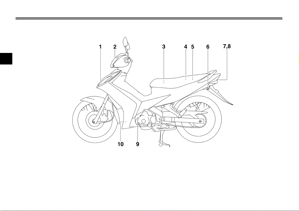
Left view
2
EAU10410
1. Front turn signal/auxiliary lights (page 6-31)
2. Headlight (page 6-30)
3. Battery (page 6-28)
4. Storage compartment (page 3-8)
5. Owner’s tool kit (page 6-1)
6. Seat lock (page 3-7)
7. Tail/brake light (page 6-31)
8. Rear turn signal lights (page 6-31)
9. Shift pedal (page 3-4)
10.Coolant reservoir (page 6-11)
2-1
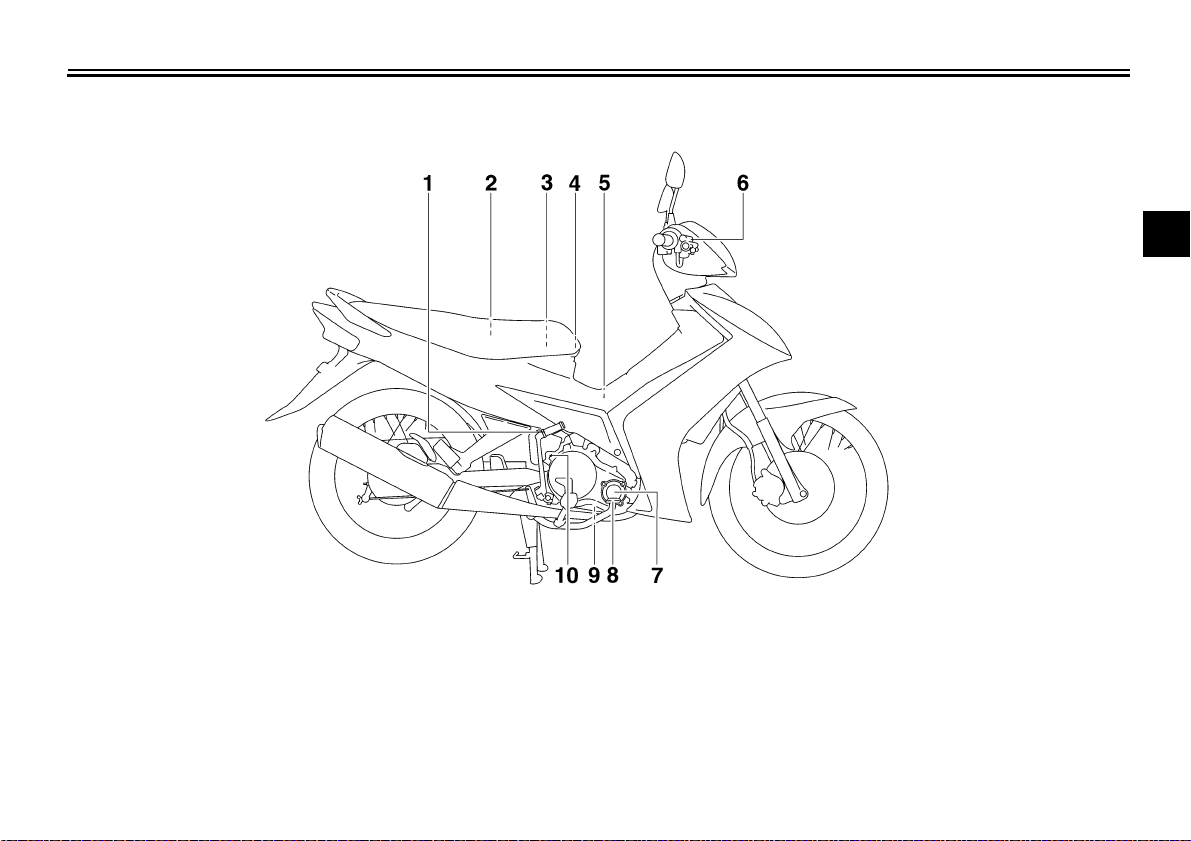
Right view
DESCRIPTION
EAU10420
2
1. Kickstarter (page 3-7)
2. Fuel tank cap (page 3-5)
3. Fuse (page 6-29)
4. Helmet holder (page 3-8)
5. Air filter element (page 6-13)
6. Front brake fluid reservoir (page 6-21)
7. Engine oil filter element (page 6-9)
8. Brake pedal (page 3-5)
9. Engine oil drain bolt (page 6-9)
10.Engine oil filler cap (page 6-9)
2-2
DESCRIPTION
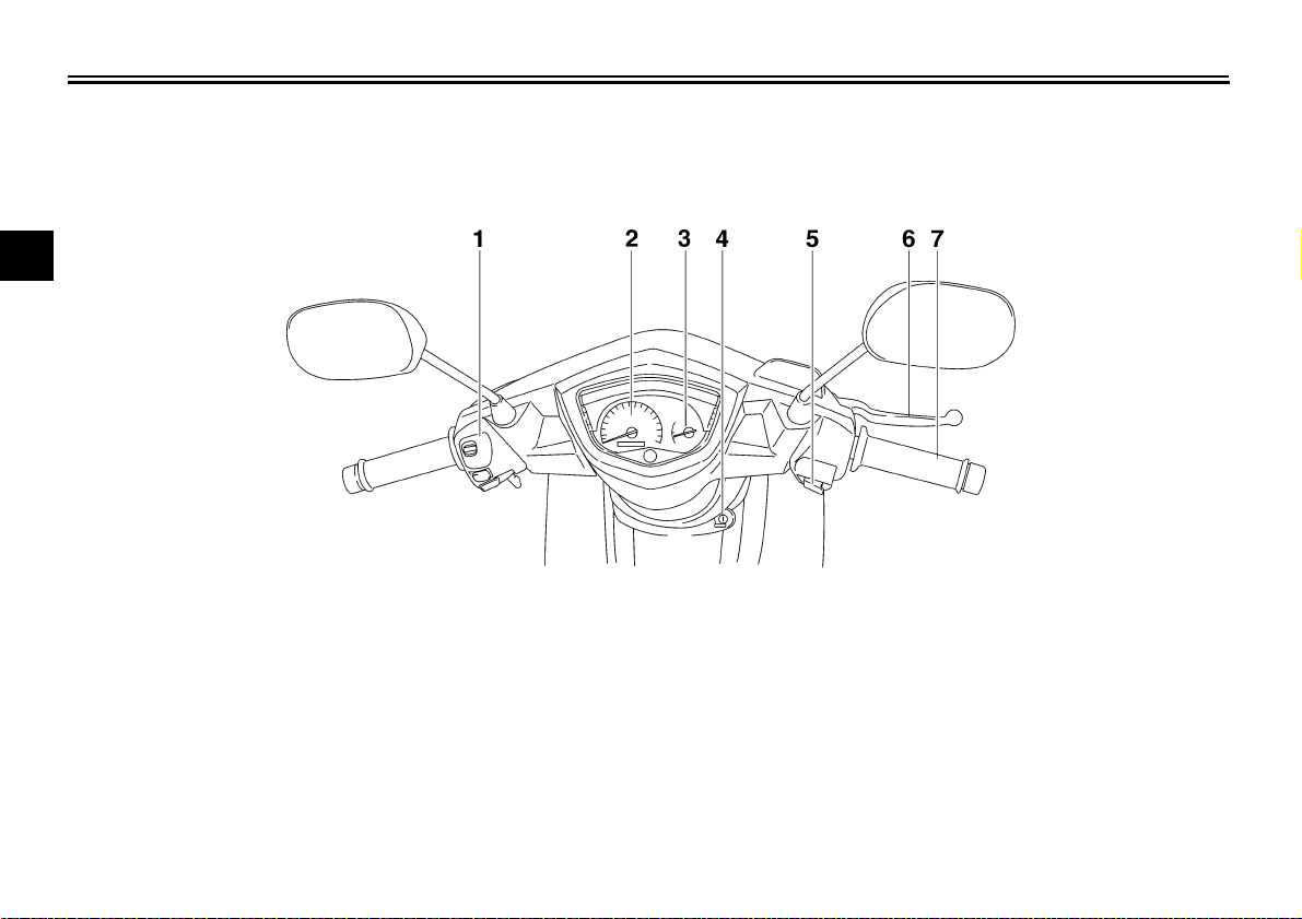
Controls and instruments
2
1. Left handlebar switches (page 3-3)
2. Speedometer unit (page 3-3)
3. Fuel gauge (page 3-3)
4. Main switch/steering lock (page 3-1)
5. Right handlebar switch (page 3-3)
6. Brake lever (page 3-4)
7. Throttle grip (page 6-15)
EAU10430
2-3
INSTRUMENT AND CONTROL FUNCTIONS
EAU10460
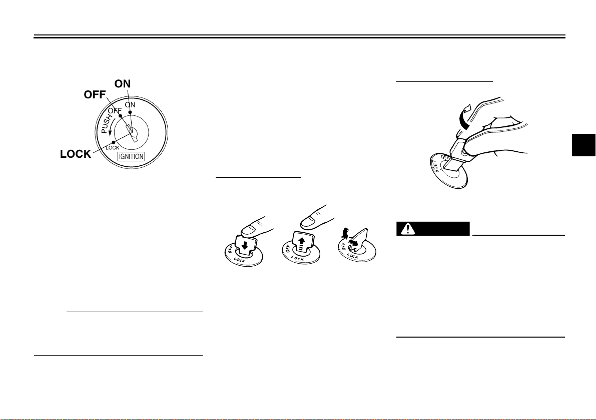
Main switch/steering lock
The main switch/steering lock controls
the ignition and lighting systems, and is
used to lock the steering. The various
positions are described below.
EAU37441
ON
All electrical circuits are supplied with
power, and the engine can be started.
The key cannot be removed.
NOTE:
The headlight, auxiliary lights, meter
lighting and taillight come on automatically when the engine is started.
OFF
EAU10660
All electrical systems are off. The key
can be removed.
EAU10700
LOCK
The steering is locked, and all electrical
systems are off. The key can be removed.
To lock the steering
123
1. Push.
2. Release.
3. Turn.
1. Turn the handlebars all the way to
the left.
2. Push the key in from the “OFF” position, release it, and then turn it to
“LOCK”.
3. Remove the key.
To unlock the steering
3
Insert the key and turn it to “OFF”.
EWA10060
WARNING
Never turn the key to “OFF” or
“LOCK” while the vehicle is moving,
otherwise the electrical systems will
be switched off, which may result in
loss of control or an accident. Make
sure that the vehicle is stopped before turning the key to “OFF” or
“LOCK”.
3-1
INSTRUMENT AND CONTROL FUNCTIONS
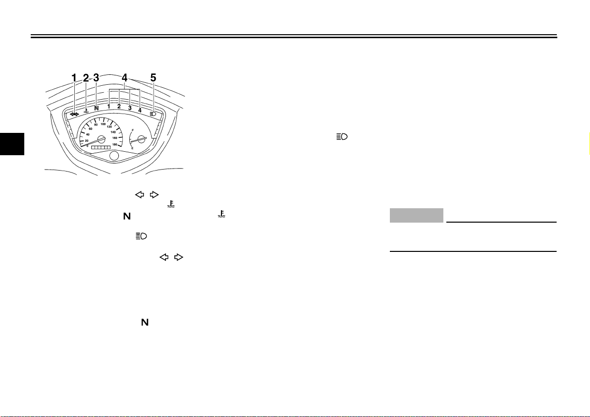
Indicator and warning lights
3
1. Turn signal indicator light “”
2. Coolant temperature warning light “”
3. Neutral indicator light “”
4. Gear position indicator light “1” “2” “3” “4”
5. High beam indicator light “”
Turn signal indicator light “”
This indicator light flashes when the
turn signal switch is pushed to the left or
right.
Neutral indicator light “”
This indicator light comes on when the
transmission is in the neutral position.
EAU11003
EAU11020
EAU11060
Gear position indicator lights “1”
EAU37611
“2” “3”, and “4”
The respective indicator light comes on
when the transmission is in the 1st,
2nd, 3rd or 4th gear position.
EAU11080
High beam indicator light “”
This indicator light comes on when the
high beam of the headlight is switched
on.
EAU37631
Coolant temperature warning light
“”
This warning light comes on when the
engine overheats. When this occurs,
stop the engine immediately and allow
the engine to cool.
This warning light also has a self-diagnosis device function for various electrical circuits.
● When the main switch is turned to
“ON” and the engine is not running, the warning light will flash if
an electrical circuit is defective. If
this occurs, have a Yamaha dealer
check the vehicle.
● When the engine is running, the
warning light will come on if the engine overheats or if an electrical
circuit is defective.
To determine which of the above is
occurring, stop the vehicle when it
is safe to do so, then turn the main
switch to “OFF”, and then back to
“ON”.
If the warning light stays on, this indicates the engine is overheating.
Keep the engine turned off and allow it to cool.
ECA10020
CAUTION:
Do not operate the engine if it is
overheated.
If the warning light flashes, this indicates there is a defective electrical circuit. Have a Yamaha dealer
check the vehicle.
The electrical circuit of the warning light
can be checked by turning the key to
“ON”.
If the warning light does not come on
for a few seconds, then go off, have a
Yamaha dealer check the electrical circuit.
3-2
INSTRUMENT AND CONTROL FUNCTIONS
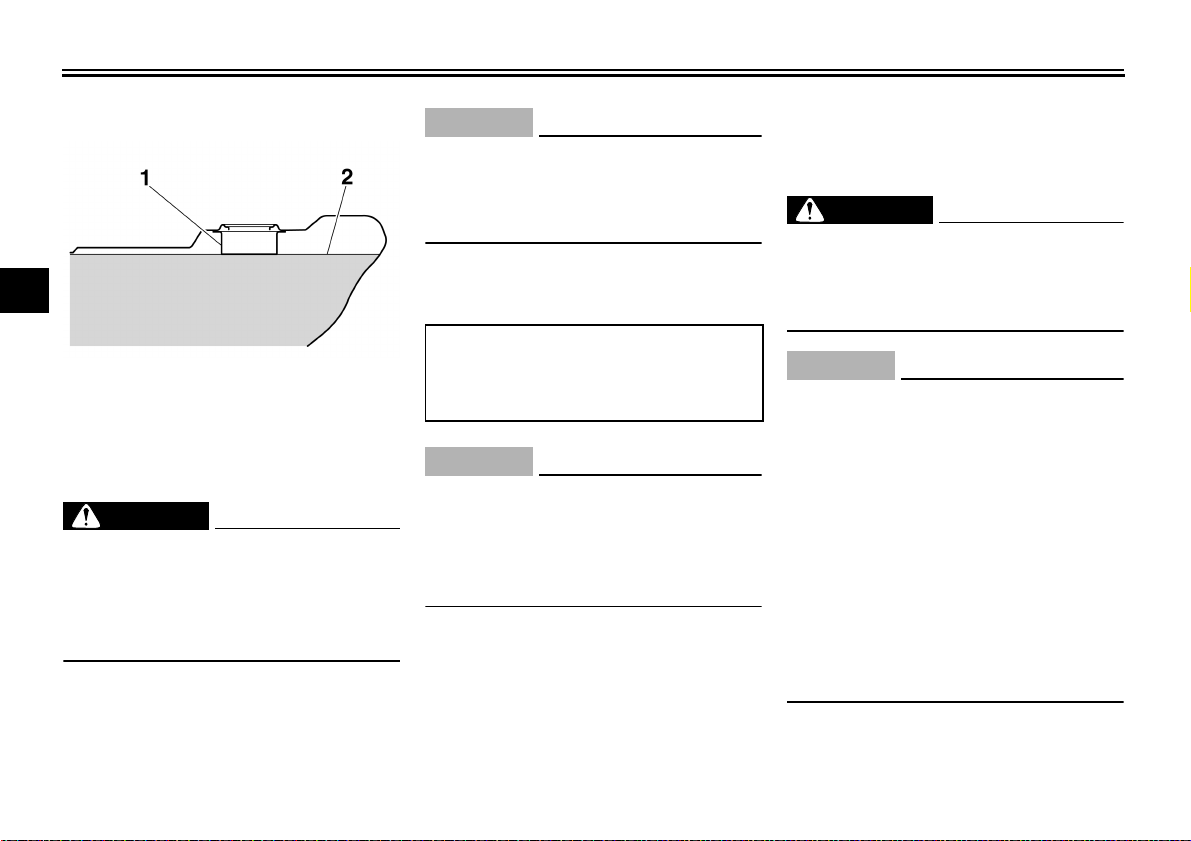
EAU11621
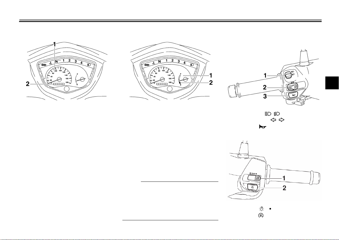
Speedometer unit
1. Speedometer
2. Odometer
The speedometer unit is equipped with
a speedometer and an odometer. The
speedometer shows riding speed. The
odometer shows the total distance traveled.
EAU37051
Fuel gauge
1. Fuel gauge
2. Red zone
The fuel gauge indicates the amount of
fuel in the fuel tank. The needle moves
towards “E” (Empty) as the fuel level
decreases. When the needle reaches
the red zone, approximately 1.0 L (0.26
US gal) (0.22 Imp.gal) remain in the
fuel tank. If this occurs, refuel as soon
as possible.
NOTE:
● Do not allow the fuel tank to empty
itself completely.
● The main switch must be turned to
“ON” for the fuel gauge to display
an accurate fuel level reading.
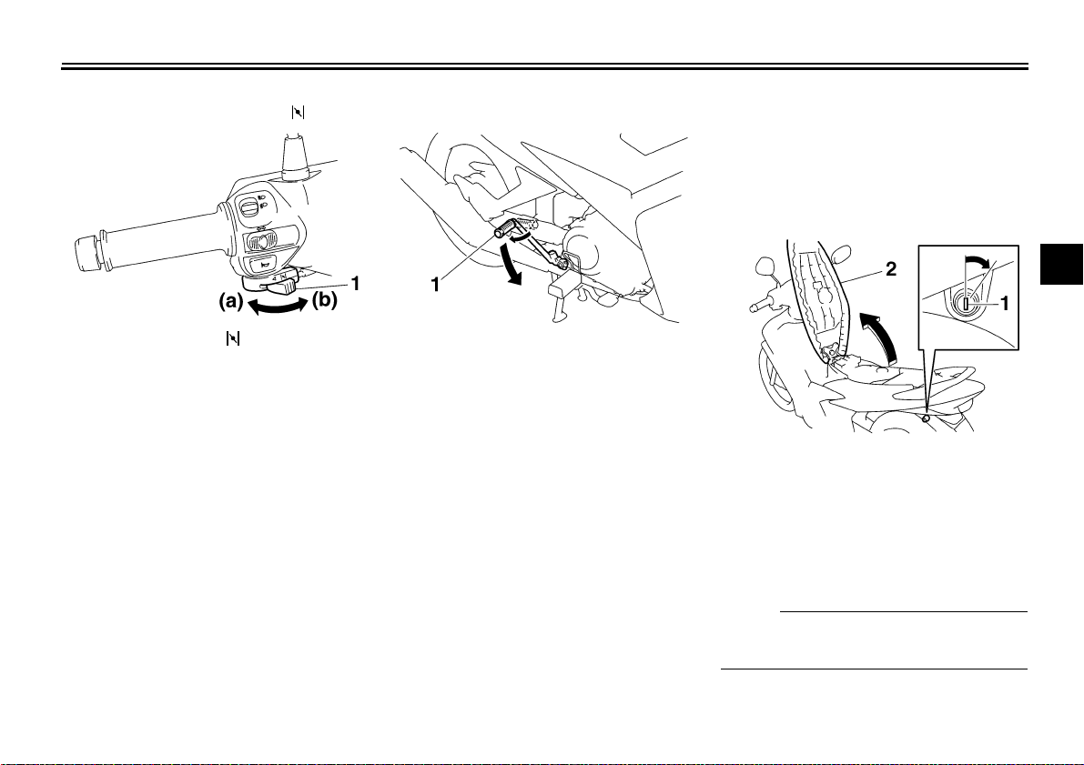
Handlebar switches
Left
1. Dimmer switch “ / ”
2. Turn signal switch “ / ”
3. Horn switch “”
Right
1. Light switch " / "
2. Start switch “”
EAU12343
3
3-3

INSTRUMENT AND CONTROL FUNCTIONS
Light switch " / "
Set the switch to " " to turn on the
position light, meter lighting, taillight
an headlight also. Set the switch to " "
to turn off all the light
Dimmer switch “ / ”
Set this switch to “”
3
beam and to “”
for the low beam.
for the high
Turn signal switch “ / ”
To signal a right-hand turn, push this
switch to “”. To signal a left-hand
turn, push this switch to “”. When re-
leased, the switch returns to the center
position. To cancel the turn signal
lights, push the switch in after it has re-
turned to the center position.
Horn switch “”
.
Press this switch to sound the horn.
Start switch “”
Push this switch to crank the engine
with the starter.
CAUTION:
See page 5-1 for starting instructions prior to starting the engine.
EAU02948
EAU12400
EAU12460
EAU12500
EAU12710
ECA10050
EAU37460
Shift pedal
1. Shift pedal 1. Brake lever
The shift pedal is located on the left
side of the engine. This motorcycle is
equipped with a constant-mesh 4
speed transmission.
Brake lever
The brake lever is located at the right
handlebar grip. To apply the front
brake, pull the lever toward the handlebar grip.
NOTE:
Use your toes to shift up and your heel
to shift down.
EAU12890
3-4
INSTRUMENT AND CONTROL FUNCTIONS
EAU12941
Brake pedal
1. Brake pedal 1. Fuel tank cap
The brake pedal is on the right side of
the motorcycle. To apply the rear
brake, press down on the brake pedal.
Fuel tank cap
2. “” mark
To remove the fuel tank cap
1. Open the seat. (See page 3-7.)
2. Turn the fuel tank cap counterclockwise and pull it off.
To install the fuel tank cap
1. Insert the fuel tank cap into the
tank opening and turn it clockwise
until the “” marks on the cap and
tank are aligned.
2. Close the seat.
EAU37470
EWA11090
WARNING
Make sure that the fuel tank cap is
properly closed before riding.
3
3-5
INSTRUMENT AND CONTROL FUNCTIONS
Fuel
3
1. Fuel tank filler tube
2. Fuel level
Make sure that there is sufficient fuel in
the tank. Fill the fuel tank to the bottom
of the filler tube as shown.
WARNING
● Do not overfill the fuel tank, oth-
erwise it may overflow when the
fuel warms up and expands.
● Avoid spilling fuel on the hot en-
gine.
EAU13210
EWA10880
ECA10070
CAUTION:
Immediately wipe off spilled fuel
with a clean, dry, soft cloth, since
fuel may deteriorate painted surfaces or plastic parts.
EAU37880
Recommended fuel:
Regular unleaded gasoline only
Fuel tank capacity:
4.0 L (1.06 US gal) (0.88 Imp.gal)
ECA11400
CAUTION:
Use only unleaded gasoline. The use
of leaded gasoline will cause severe
damage to internal engine parts,
such as the valves and piston rings,
as well as to the exhaust system.
EAU13431
Catalytic converter
This model is equipped with a catalytic
converter in the exhaust system.
EWA10860
WARNING
The exhaust system is hot after operation. Make sure that the exhaust
system has cooled down before doing any maintenance work.
ECA10700
CAUTION:
The following precautions must be
observed to prevent a fire hazard or
other damages.
● Use only unleaded gasoline.
The use of leaded gasoline will
cause unrepairable damage to
the catalytic converter.
● Never park the vehicle near pos-
sible fire hazards such as grass
or other materials that easily
burn.
● Do not allow the engine to idle
too long.
3-6
INSTRUMENT AND CONTROL FUNCTIONS
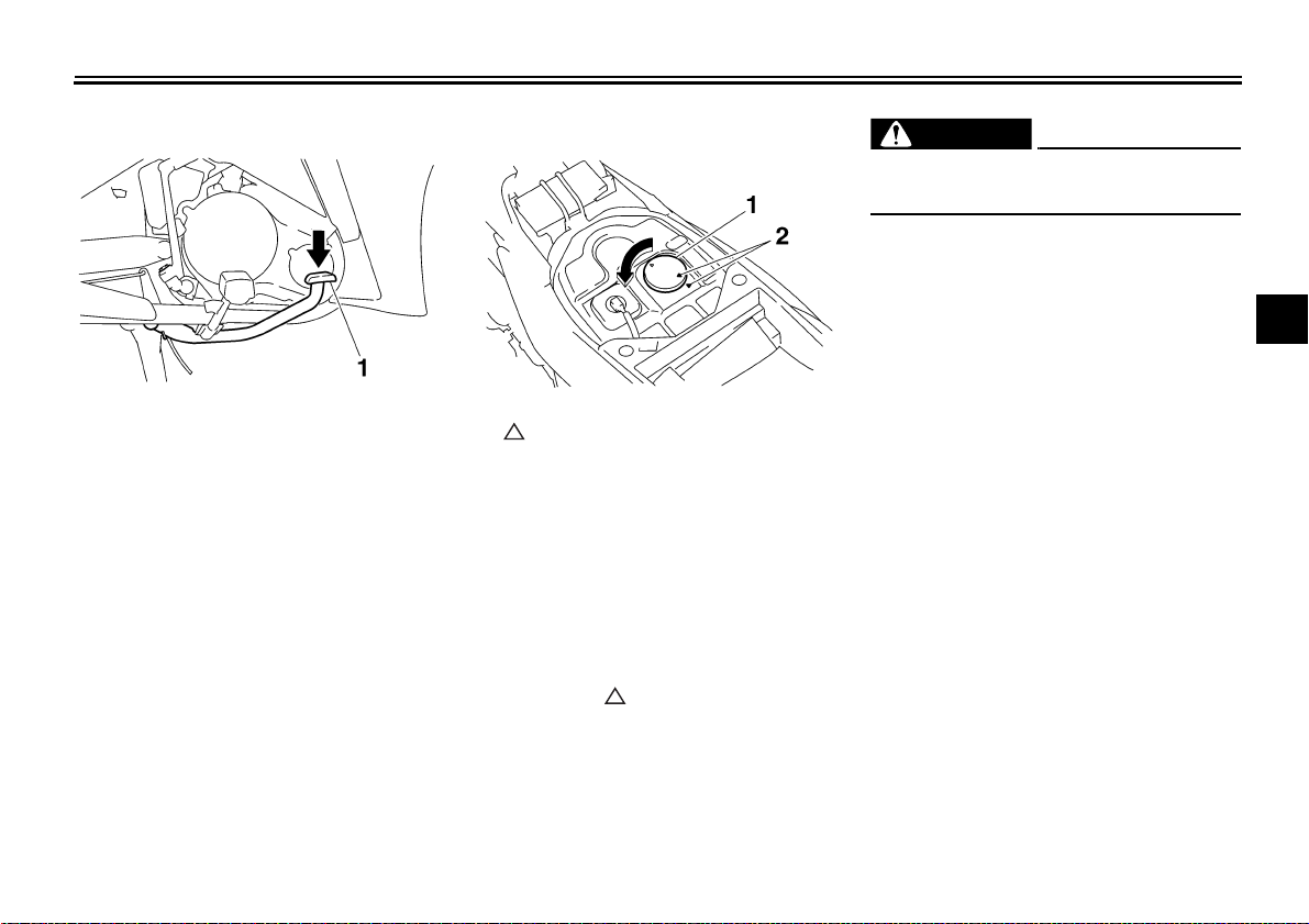
EAU13590
Starter (choke) lever “”
1. Starter (choke) lever “” 1. Kickstarter
Starting a cold engine requires a richer
air-fuel mixture, which is supplied by
the starter (choke).
Move the lever in direction (a) to turn on
the starter (choke).
Move the lever in direction (b) to turn off
the starter (choke).
Kickstarter
If the engine fails to start by pushing the
start switch, try to start it by using the
kickstarter. To start the engine, fold out
the kickstarter lever, move it down lightly with your foot until the gears engage,
and then push it down smoothly but
forcefully.
EAU37650
EAU13891
Seat
To open the seat
1. Insert the key in the lock, and then
turn it as shown.
2. Fold the seat up.
3
1. Seat lock
2. Seat
To close the seat
1. Fold the seat down, and then push
it down to lock it in place.
2. Remove the key.
NOTE:
Make sure that the seat is properly secured before riding.
3-7
INSTRUMENT AND CONTROL FUNCTIONS
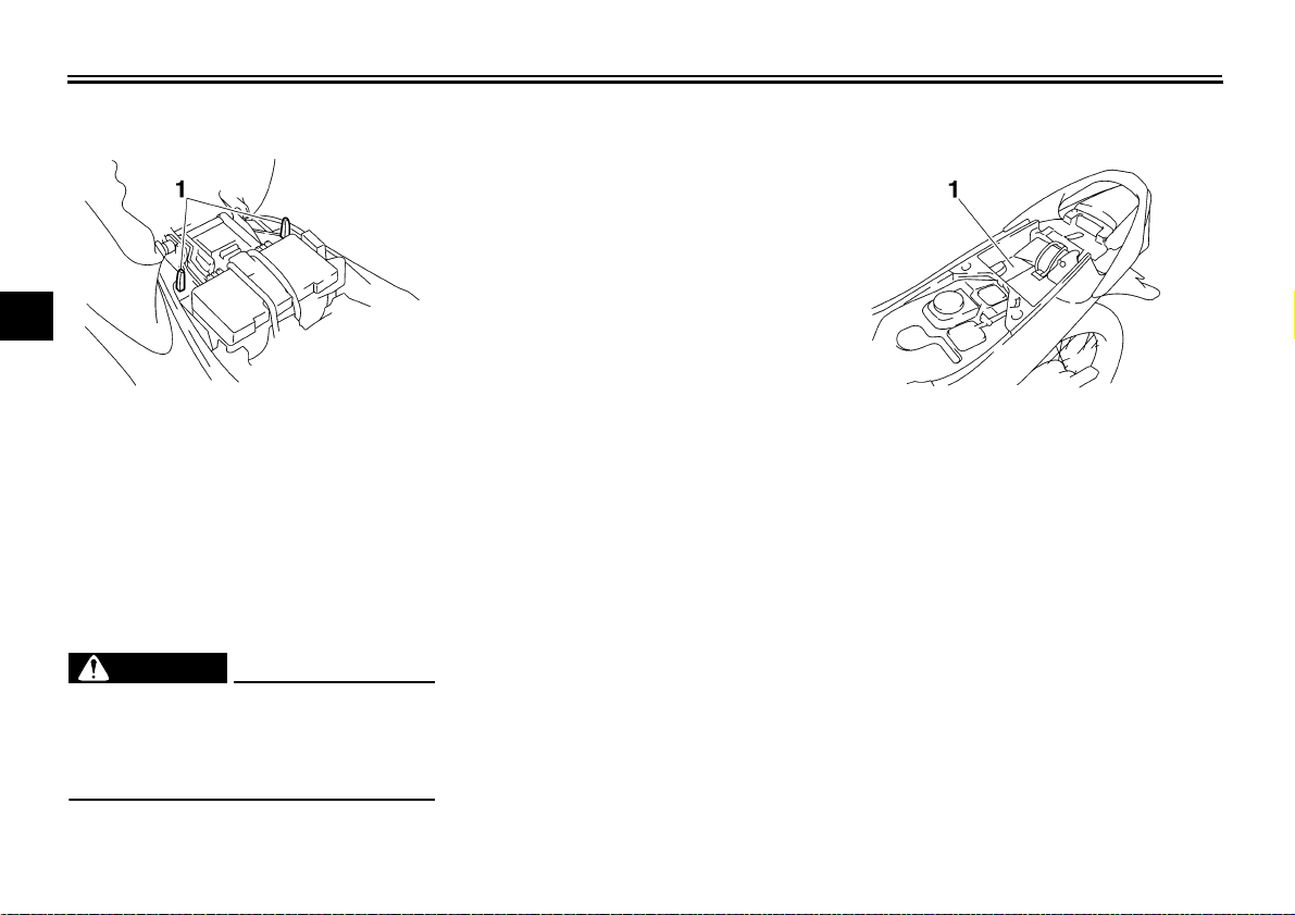
EAU37480
Helmet holders
To release a helmet from a helmet
holder
Storage compartment
Open the seat, remove the helmet from
the helmet holder, and then close the
seat.
3
1. Helmet holder 1. Storage compartment
The helmet holders are located under
the seat.
The storage compartment is located
under the seat. (See page 3-7.)
When storing the owner’s manual or
To secure a helmet to a helmet holder
1. Open the seat. (See page 3-7.)
2. Attach a helmet to a helmet holder,
and then securely close the seat.
EWA10160
other documents in the storage compartment, be sure to wrap them in a
plastic bag so that they will not get wet.
When washing the vehicle, be careful
not to let any water enter the storage
compartment.
WARNING
Never ride with a helmet attached to
the helmet holder, since the helmet
may hit objects, causing loss of control and possibly an accident.
EAU37890
3-8
EAU37490
Sidestand
The sidestand is located on the left side
of the frame. Raise the sidestand or
lower it with your foot while holding the
vehicle upright.
EWA14190
WARNING
The vehicle must not be ridden with
the sidestand down, or if the sidestand cannot be properly moved up
(or does not stay up), otherwise the
sidestand could contact the ground
and distract the operator, resulting
in a possible loss of control.
INSTRUMENT AND CONTROL FUNCTIONS
3
3-9
PRE-OPERATION CHECKS
The condition of a vehicle is the owner’s responsibility. Vital components can start to deteriorate quickly and unexpectedly,
even if the vehicle remains unused (for example, as a result of exposure to the elements). Any damage, fluid leakage or loss
of tire air pressure could have serious consequences. Therefore, it is very important, in addition to a thorough visual inspection, to check the following points before each ride.
NOTE:
Pre-operation checks should be made each time the vehicle is used. Such an inspection can be accomplished in a very short
time; and the added safety it assures is more than worth the time involved.
4
WARNING
If any item in the Pre-operation check list is not working properly, have it inspected and repaired before operating
the vehicle.
EAU15591
EWA11150
4-1
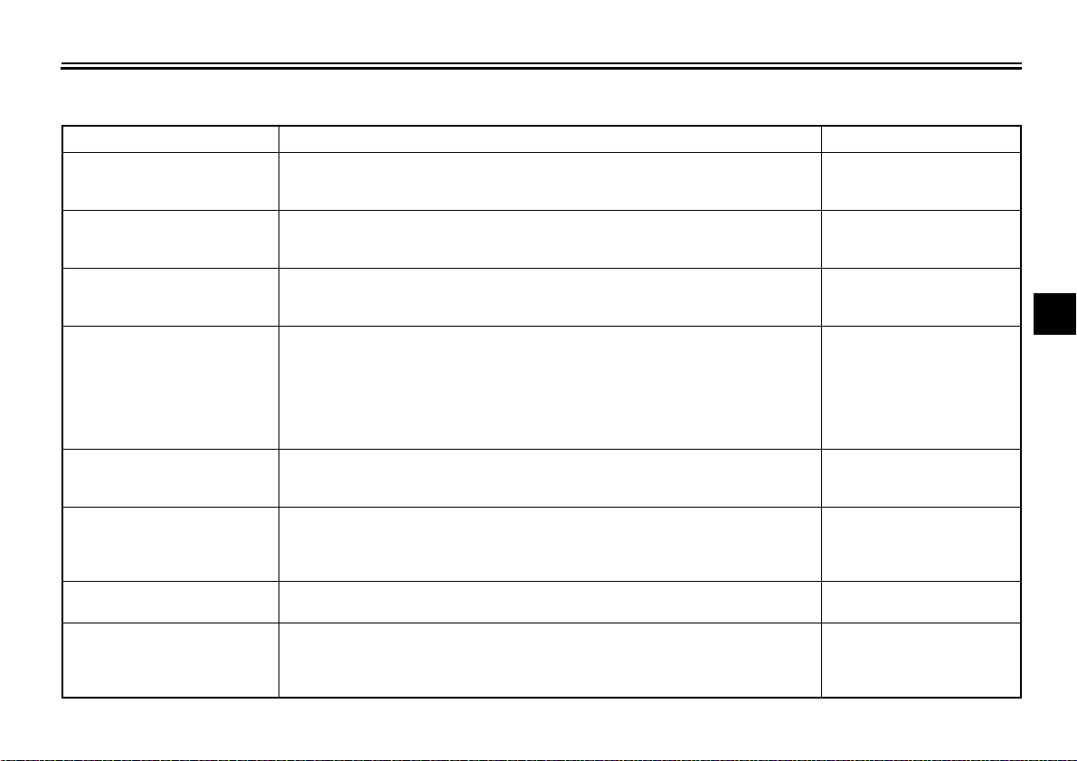
Pre-operation check list
ITEM CHECKS PAGE
Fuel
Engine oil
Coolant
Front brake
Rear brake
Throttle grip
Control cables
Drive chain
• Check fuel level in fuel tank.
• Refuel if necessary.
• Check fuel line for leakage.
• Check oil level in engine.
• If necessary, add recommended oil to specified level.
• Check vehicle for oil leakage.
• Check coolant level in reservoir.
• If necessary, add recommended coolant to specified level.
• Check cooling system for leakage.
• Check operation.
• If soft or spongy, have Yamaha dealer bleed hydraulic system.
• Check brake pads for wear.
• Replace if necessary.
• Check fluid level in reservoir.
• If necessary, add recommended brake fluid to specified level.
• Check hydraulic system for leakage.
• Check operation.
• Check pedal free play.
• Adjust if necessary.
• Make sure that operation is smooth.
• Check cable free play.
• If necessary, have Yamaha dealer adjust cable free play and lubricate cable and
• Make sure that operation is smooth.
• Lubricate if necessary.
• Check chain slack.
• Adjust if necessary.
• Check chain condition.
• Lubricate if necessary.
PRE-OPERATION CHECKS
EAU15603
3-6
6-9
6-11
4
6-20, 6-21
6-20
6-15, 6-24
grip housing.
6-24
6-22, 6-23
4-2
PRE-OPERATION CHECKS
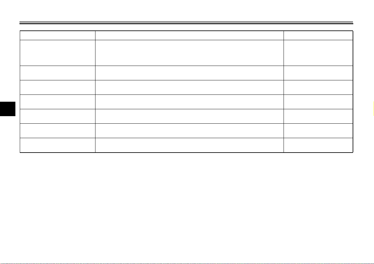
ITEM CHECKS PAGE
• Check for damage.
Wheels and tires
Brake pedal
Brake lever
Centerstand, sidestand
4
Chassis fasteners
Instruments, lights, signals
and switches
Battery
• Check tire condition and tread depth.
• Check air pressure.
• Correct if necessary.
• Make sure that operation is smooth.
• Lubricate pedal pivoting point if necessary.
• Make sure that operation is smooth.
• Lubricate lever pivoting point if necessary.
• Make sure that operation is smooth.
• Lubricate pivots if necessary.
• Make sure that all nuts, bolts and screws are properly tightened.
• Tighten if necessary.
• Check operation.
• Correct if necessary.
• Check fluid level.
• Fill with distilled water if necessary.
6-16, 6-18
6-25
6-25
6-25
—
—
6-28
4-3
 Loading...