

Page 1
ABCDEFGH I JK
RX-V795a/RDS/HTR-5170/DSP-R795a
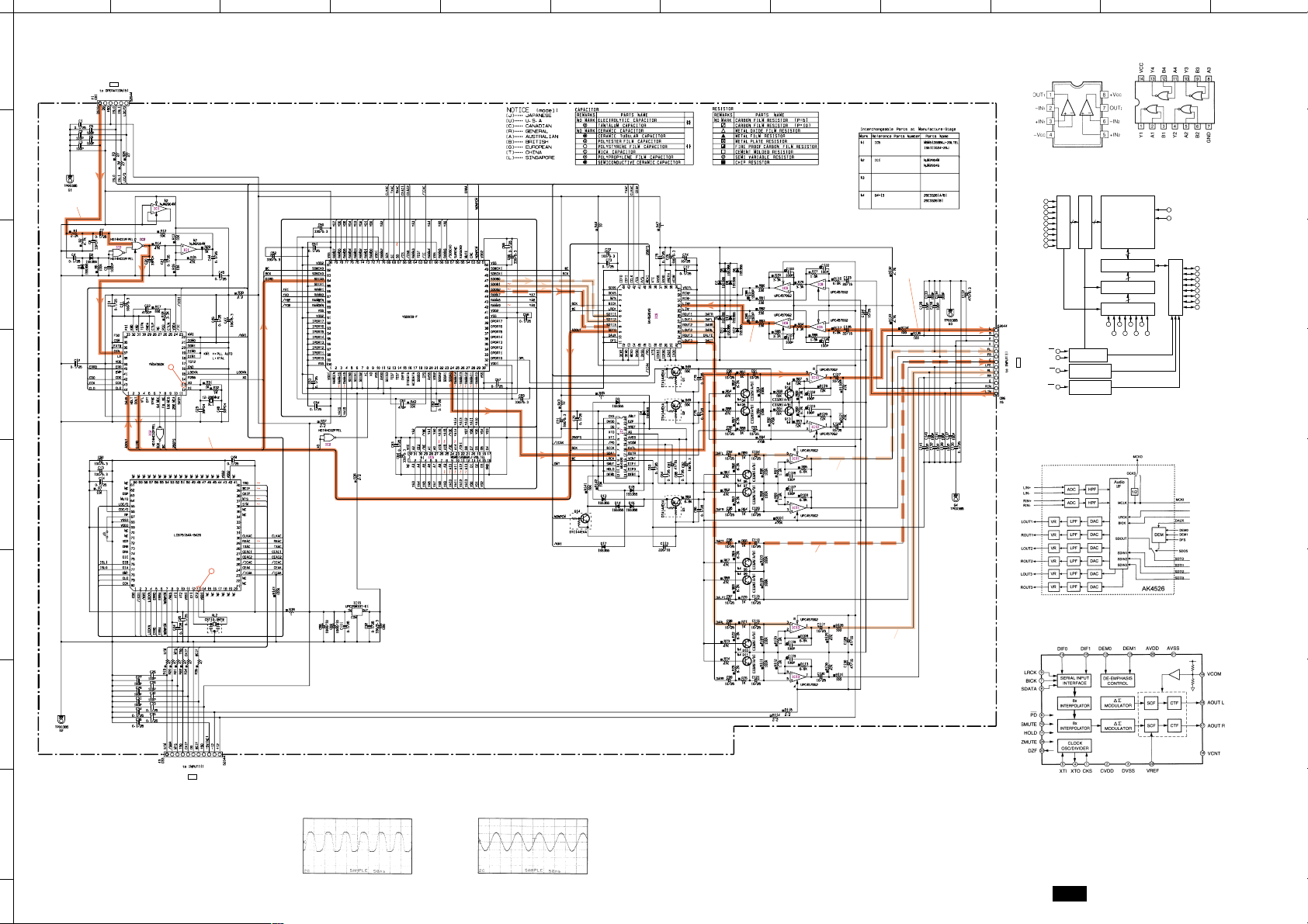
■ SCHEMATIC DIAGRAM (DSP)
1
P-E69/J59
F-2
4.704.904.9
0
IC1 : NJM2904M
IC8~11, 13 :
Dual OP Amp
µPC4570G2
IC2 : HD74HC02FPEL
Quad 2 Input NOR
L
2
IC5 : M5M51288BKJ-20L
4.9
38
DIGITAL IN
00
3
4
5
6
0
0
0
0
1
4
2
0
4.9
14
11
0
0
2.6
4.9
7
0
000
4.904.9
13
0
DIR
IC3
5
4.9
2.2
2.4
2.4
2.4
6
4
0
5
6
2.2
4.9
4.9
2.2
5
2.3
4.9
2.4
IC14
0
4.9
4.902.3
7
0.1
0
0
0
0
0
0
4.9
2.4
2.3
DIGITAL IN
2.6
4.9
0
4.9
4.9
4.9
0
4.9
4.9
4.9
4.9
4.9
4.9
8
12
0
10
9
0
0
0
4.9
4.9
4.9
0
4.9
2.5
0
4.9
0
0
4.9
4.9
0
0
4.9
0
0
0
0.9
0.9
0.1
0.1
0.1
0.1
4.8
2.4
4.904.9
4.9
2.4
3.1
2.4
2.4
2.6
0
2.4
0.9
4.7
0.1
0
3.1
0
0
0
0
0
0
0
0
0
DIGITAL PRO-LOGIC
4.8 0
000
2.4
2
2.4
1
3
IC4
DSP
+
DTS DECODER
2.403.1
4.8
2.4
4.8
2.4
2.4
RAM
4.963.3
0
4.9
1.503.1
4.7
2.4
2.402.4
2.4
2.4
0
0
2.4
3.1
0
2.4
2.4
0
2.4
2.4
3.1
0
4.7
4.8
0
0.9
0.1
0
0.9
0.900
0.1
2.4
2.4
0.1
0.1
0.1
0
0
00
0 2.4
0 2.4
2.4 2.4
2.4 2.4
0 2.4
2.5 2.4
0 2.4
0 2.4
0
0
0
00
0
4.9
0
2.3
4.9
2.4
2.4
0
0
4.9
0.5 0
0 0.2 0.2
0.5
4.9
4.9
0
0 0.5
4.9
4.9
DAC
4.804.9
0
4.9
0
4.9
2.4
2.4
2.4
0
4.9
0
0
2.4
4.8
0
0
4.8
2.3
0
000
0
4.7
0
0
0.2
0
4.8
4.8
0
2.4 2.4
4.8
4.8
2.4
2.4
2.42.4
2.4
00
2.4
11.5
2.4
7
2.4
1
2.42.4
-11.5
00
2.4
6
2.4
2.4
8
2.4
6
7
5
2.4
4
-11.5
5
11.5
3
2.4
3
8
2.4
2.4
2.4
2
1
2
4
2.4
MAIN L
MAIN L
4.7
0
-10.9
-10.9
0
-10.9
0
0
-10.9
0
0
-10.9
0
0
-10.9
0
0
-10.9
0
0
-10.9
0
0
-10.9
0
0
-10.9
0
0.6
0.6
0
0
0
0
0
0
0
0
0
0
0
0
0
11.5
0
0
0
-11.5
CENTER
0
11.5
0
0
0
-11.5
11.5
0
0
-11.5
FRONT L
P-E66/J56
REAR L
A0
A1
A2
A3
A4
A5
A6
A7
ADDRESS INPUT
A8
D-1
IC6 : AK4526
A/D
IC7 : AK4320
1 bit D/A Converter
RAM
LINE INPUT BUFFER
S1
S2
W
OE
18 512
DECODER
LINE ADDRESS
CHIP SELECT
CIRCUIT
WRITE ENABLE
CONTROL INPUT
OUTPUT ENABLE
CONTROL INPUT
MEMORY ARRAY
131072X8bit
512X2048
2048
COLUMN I/O CIRCUIT
256
COLUMN
ADDRESS DECODER
16
COLUMN
INPUT BUFFER
A9
A11
A13
A15
A10
A12
A14
Vcc(5V)
GND(0V)
DQ1
DQ2
DQ3
DQ4
DQ5
DQ6
I/O DATA
DATA I/O
DQ7
DQ8
CONTROL CIRCUIT
A16
7
8
E-65/J-55
P-E66/J56
G-8
Point t (Pin13 of IC3)
V : 2V/div H : 50 nsec/div
DC range 1 : 1 probe
Point y (Pin13 of IC14)
V : 2V/div H : 50 nsec/div
DC range 1 : 1 probe
Other ICs
● IC3 : YM3436DK → See page E-27/J-23
● IC4 : YSS918-F → See page E-28/J-24
● IC14 : LC87F5164 → See page E-31/J-27
* All voltage are measured with a 10MΩ/DC electric volt meter.
* Components having special characteristics are marked
must be replaced with parts having specifications equal to those
originally installed.
* Schematic diagram is subject to change without notice.
Z
and
DSP
Page 2
ABCDEFGHI JK
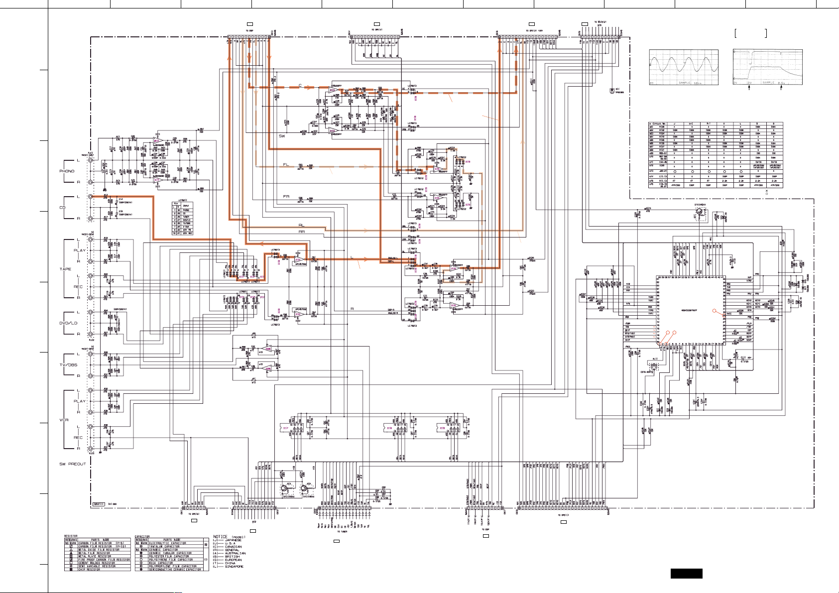
■ SCHEMATIC DIAGRAM (INPUT)
1
2
PHONO MM EQ AMP
3
4
5
6
8
11.2
0
3
0
0
2
1
6
0
0
5
0
7
-11.1
4
INPUT SELECTOR
0000000
000
000
000
0
P-E65/J55
J-4
0
0
000
0
0
0
TAPE MONITOR
3
8
1
2
6
7
5
4
P-E69/J59
P-E69/J59
I-3
A-5
P-E71/J61
A-5
Point e (Pin3 of IC21)
V : 2V/div H : 50 nsec/div
DC range 1 : 1 probe
RX-V795a/RDS/HTR-5170/DSP-R795a
Point r
CH1 : Pin1 of IC21
CH2 : Pin29 of IC21
H : 0.5 sec/div DC range 1
(This waveform is not available by pushing the power switch ON and OFF.)
: 1 probe
V : 2V/div (CH1)
V : 2V/div (CH2)
0V
21.8
3
0
8
0
2
0
1
0.1
6
0.1
0.1
5
7
4
-22.2
FRONT L
11.6
0
5
0
8
0
6
7
0
MAIN L
0
2
0
3
0
1
-11.5
0
4
0
0
0
0
0
0.3
0.3
0
00
0
0
0
0
0
0
0
0
0
0
0
0
0
0
0
0
0
CENTER
MAIN L
0
2
0
8
21.8
000
0
1
3
0
0
5
0
0
0
6
0
000
7
-22.2
4
0
0
0
0
0
0
5
8
0
0
7
6
2
0
0
3
0
0
1
4
-22.2
REAR R
CIRCUIT CHANGES BY MARKET.
4.9
0
4.8
0
4.9
4.9
0
0
4.9
0
0
4.9
4 3
4.9
4.8
4.7
2.0
2.2
-11.4
4.9
4.9
4.9
4.9
4.90000
0
IC21
0
000
4.9
4.9
4.9
4.9
4.7
4.9
4.9
4.900
4.904.9
4.9
4
0
0
4.9
4.5
0
4.9
With the POWER ON, disconnect the A/C power cord.
Reconnect the A/C power
cord and the above waveforms will start.
4.5
4.9
0
1.4
0.3
1.2
0
4.9
4.9
4.9
0.1
4.9
0
4.9
0
0
4.9
0
0
Disconnect the power cord
from the AC outlet.
: NOT USED
: USED
0.7
0
0.3
0.3
0.2
0
0
1.2
0
4.7
4.7
4.9
0
0
0
11.6
11.6
000
-11.5
0
0
11.6
11.6
000
-11.5
0
11.6
11.6
000
-11.5
4.9
7
11.3
4.9
0000
P-E69/J59
8
C-2
TO VIDEO(1)
P-E67/J67
D-8
P-E72/J62 (J,U,C,A,L,R,T models)
P-E73 (B,G models)
H-5
P-E65/J55
B-8
P-E68/J58
H-2
* All voltage are measured with a 10MΩ/DC electric volt meter.
* Components having special characteristics are marked
must be replaced with parts having specifications equal to those
originally installed.
* Schematic diagram is subject to change without notice.
INPUT
Z
and
E-66/J-56
Page 3
ABCDEFGH I JK
RX-V795a/RDS/HTR-5170/DSP-R795a
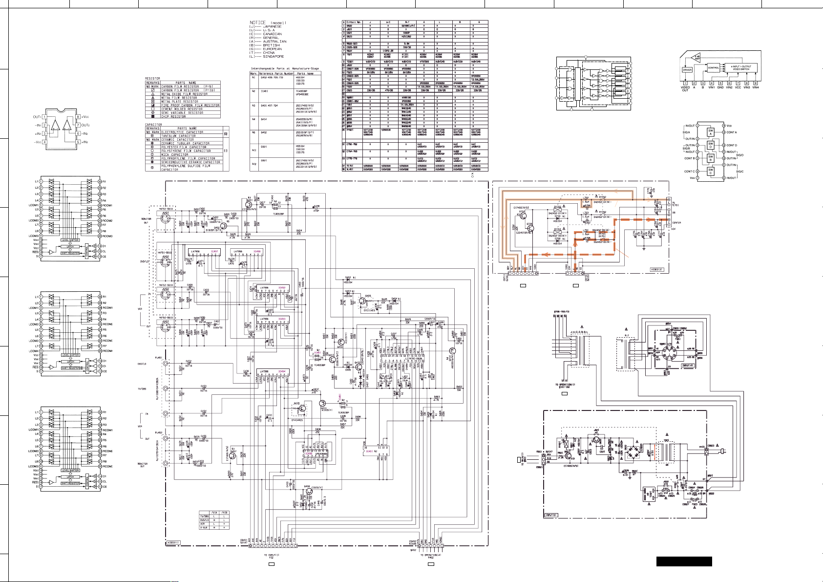
■ SCHEMATIC DIAGRAM (INPUT & VIDEO)
1
IC11 : NJM2068MD
µPC4570G2
IC12, 20 :
IC13, 15, 16 : M5220FP
2
3
Dual OP Amp
IC17 : LC78211
Analog Function Switch
4
IC18 : LC78213
Analog Function Switch
5
6
IC19 : LC78212
Analog Function Switch
7
S-VIDEO AMP & SELECTOR
11.1
2.1
1.5
0.1
0.3
0
0
3.8
5.3
11.1
11.5
11.3
3.8
11.1
5.0
11.1011.5
3.8
5.6
3.8
5.3
11.3
3.8
11.1
11.1
3.8
11.1
3.8
3.8
2.5
3.803.8
3.803.8
3.803.8
2.5
2.5
11.5
11.3
5.7
11.5
11.3
5.7
11.5
11.3
5.6
11.3
0.5
0.5
SYNC SIGNAL
DETECTOR
5.0
4.3
4.3
4.4
4.9
1.9
1.1
3.4
0
0
11.1
0
11.100
11.1
0
5.6
0
11.1
11.5
5.6
5.6
5.6 11.1
CIRCUIT CHANGES BY MARKET.
0
5.0
0
1.1
2.2
1.1 1.5
1.0
0.5
0
2.72.72.7
1.1
5.0
SUPERIMPOSE
000
5.005.002.0
5.0
IC406
0 5.0
0
2.4
2.5
0.1
2.4
2.4
0.1
0.5
0.5
5.0
5.0
000
5.0
4.9
1.1
4.905.0
L
IC402~404, 407, 408 : LA7956
Video Switch
IC405 : µPD4066BC
Quad Analog Switch/Multiplexer
: NOT USED
: USED
INH
0.7
1.3
SPEAKER
0.7
0.7
0.7
0
0.7
RELAY DRIVE
IC401 : TC4053BP
Triple 2-Channel Analog Multiplexers/
Demultiplexers
VDD
16
11
A
10
B
9
C
LOGIC LEVEL CONVERTER
6
7
8
VEE
VSS
REAR L
23.8
23.8
OUT C IN
OUT C IN
OUT C IN
OUT C IN
OUT C IN
OUT C IN
14
12
13
2
1
5
3
4
15
X-COMMON
OX
IX
OY
IY
OZ
IZ
Z-COMMON
Y-COMMON
CENTER
TO MAIN (2)
P-E71/J61
G-2
0
1.1
1.8
1.1
0
0.5
0
I-6
P-E70/J60
TO MAIN (1)
P-E70/J60
I-5
TO MAIN (5)
TO MAIN (1)
P-E68/J58
A-1
SUB POWER SUPPLY
8.8
8.8
9.3
0
0.7
0
9.8
9.3
0
AC12.6
9.8
0
8
E-67/J-57
Other ICs
● IC21 : HD6433397A97F → See page E-36/J-30
● IC406 : LC74781-9626 → See page E-35/J-29
P-E66/J56
11.1
5.0
5.7
5.7
0
D-8
REGULATOR
P-E69/J59
* All voltage are measured with a 10MΩ/DC electric volt meter.
* Components having special characteristics are marked
must be replaced with parts having specifications equal to those
originally installed.
* Schematic diagram is subject to change without notice.
I-2
INPUT & VIDEO
Z
and
Page 4

ABCDEFGHI JK
■ SCHEMATIC DIAGRAM (OPERATION)
1
RX-V795a/RDS/HTR-5170/DSP-R795a
P-E67/J57
P-E70/J60
I-6
I-4
P-E66/J56
H-8
2
-13.3
-22.3
-22.3
3
-22.5
-29.6
4
0.6
0.6
0
5
4.9
FULL MUTE DRIVE
-13.3
0
4.9
4.9
5.65.68.8
4.9
4.9
5.6
4.4
4.9
-11.4
RESET
8.8
8.8
8.1
5.7 6.3
6
0
4.8
0
0
0
0
-28.9
-23.6
-28.8
-27.8
-27.8
-28.0
-27.9
-27.9
-27.9
-27.9
-27.9
-27.9
-27.9
-28.1
-28.0
-28.0
-27.9
-27.9
-27.9
-27.9
-27.9
-28.1
4.74.7
-27.8
DISPLAY DRIVE
0
0
2.3
2.4
4.7
-27.9
-27.9
-27.9
-27.9
-27.9
4.904.9
-27.9
-29.6
-27.9
-27.9
-27.9
-27.9
-27.9
-27.9
-27.9
-27.9
-28.1
4.7
-27.8
-28.9
-23.6
-28.8
0
4.7
0
CIRCUIT CHANGES BY MARKET.
0
4.9
4.9
: NOT USED
IC102 : LC75710NE
FL Display Driver
SYSTEM CONTROL
7
Other IC
8
● IC102 : LC75712E → See page E-35
* All voltage are measured with a 10MΩ/DC electric volt meter.
* Components having special characteristics are marked
must be replaced with parts having specifications equal to those
originally installed.
* Schematic diagram is subject to change without notice.
OPERATION
Z
and
E-68/J-58
Page 5

ABCDEFGH I JK
RX-V795a/RDS/HTR-5170/DSP-R795a
■ SCHEMATIC DIAGRAM (OPERATION)
1
IC351 : TC74HCU04AP
Hex Inverters
L
4.8
2.5
3.1
0.3
0
0
4.8
0
0
00
00
4.8
4.8
2
C-8
P-E66/J56
4.8
0
4.3
4.8
0
4.3
4.8
0
4.3
DIGITAL IN
DIGITAL SELECTOR
0
4.8
0
4.3 4.8
0
0.3
0
0
4.8
4.8
4.8
4.80000
0
4.9
0
G-8
P-E67/J57
0
4.3
4.3
4.804.8
B-1
P-E65/J55
to VIDEO (1)
IC352 : HD74HC00P
Quadruple 2-input Positive NAND Gates
3
E-1
P-E66/J56
11.3
3
0
8
0
2
0
4
5
P-E66/J56
G-1
MAIN
1
0
6
7
0
0
4
5
-11.3
3
0
8
11.3
0
0
2
1
6
0
0
0
7
4
5
-11.3
11.3
3
0
8
0
0
2
1
6
6
0
7
0
0
4
5
VOLUME AMP
0.1
0.1
4.8
2.0
0
-11.3
0
0.5
0.7
1.204.5
4.5
0.7
0.5
10.4
10.4
7
SPEAKER SETTING CONTROL
CENTER
11.3
2
0
8
0
3
0000000
0000000
REAR L
0000000
0
0
000
11.3
0
-11.3
11.3
11.3
0
11.3
1
5
0
0
0
7
4
6
-11.3
11.3
2
0
8
0
0
3
1
0
5
0
0
7
4
6
-11.3
SPEAKER LEVEL CONTROL
P-E70/J60
A-4
P-E71/J61
IC353 : HD74HC153P
Dual 4 to 1 Data Selectors
A-5
11.5
0
0
0
0
0
0
-11.4
11.5
0
0
0
0
0
0
-11.4
CIRCUIT CHANGES BY MARKET.
: NOT USED
IC255, 256 : TC9299P
Electric Controlled Volume
8
E-69/J-59
MOTOR DRIVE
IC201 : NJM2068LD
Dual OP Amp
+
–+–
2
3
4
5
6
1
1
1
2
2
1
CC
–IN
–IN
+IN
+IN
–V
OUT
IC254 : LB1641
IC202 : µPC4570HA
Dual OP-Amp
1
2
– +
7
8
2
CC
+V
OUT
2
1
VCC
–Vm
VO1
– +
3
4
5
6
7
8
9
EE
CC
V
+Vm
1
1
V
+Vm
–Vm
V
2
2
O2
IC251~253, 257, 258 : µPC4570G2
Dual OP-Amp
Motor Driver
* All voltage are measured with a 10MΩ/DC electric volt meter.
* Components having special characteristics are marked
must be replaced with parts having specifications equal to those
originally installed.
* Schematic diagram is subject to change without notice.
Z
and
OPERATION
Page 6

ABCDEFGHI JK
■ SCHEMATIC DIAGRAM (MAIN)
1
2
Each voltage given here represents that in the top side of IMPEDANCE SELECTOR, but
the one in the parentheses ( ) is that in the bottom side.
RX-V795a/RDS/HTR-5170/DSP-R795a
13.6
3
0
-11.4
0
0
-11.4
4
0
MUTING
MAIN L
POWER AMP
0.6
0
-48.1
0
0.9
0
-48.8
-1.0
-1.0
-48.1
-48.6
MAIN L
5
E-5
P-E69/J59
0
-11.4
0
0
-11.4
0
MUTING
6
MAIN R
POWER AMP
0.6
0
0
-48.0
-48.8
1.0
-1.0
-1.0
-48.0
-48.5
CENTER
CENTER
0.6
0
7
0
-11.4
0
0
-48.1
-48.8
MUTING
POWER AMP
1.0
-1.0
-1.0
-48.1
-48.6
48.8
(40.5)
0.9
0.4
-0.4
-0.4
-1.0
-48.9 (-40.5)
48.8 (40.5)
1.0
0.4
-0.4
-0.5
-1.0
-48.9 (-40.5)
48.8 (40.5)
1.0
0.4
-0.4
-0.5
-1.0
-48.9 (-40.5)
48.8
(40.5)
48.6
0
48.8
(40.5)
0.4
0
0
-0.4
-48.9 (-40.5)
48.8
(40.5)
0.4
0
0
-0.5
-48.9 (-40.5)
48.8
(40.5)
0.4
0
0
-0.5
-48.9 (-40.5)
48.6
0
0
B-1
P-E68/J58
G-5
P-E71/J61
48.4
0
0
-42.2
-29.6
-30.2
0
24.1
SPEAKER RELAY
0.7
0.7
0.6
0
48.5
0
0
POWER SUPPLY
48.8
(40.5)
DRIVE
1.2
0
±B
-48.9
(-40.5)
TO VIDEO (2)
I-5
P-E67/J57
G-5
P-E71/J61
P-E67/J57
P-E71/J61
H-7
CIRCUIT CHANGES BY MARKET.
: NOT USED
G-5
8
* All voltage are measured with a 10MΩ/DC electric volt meter.
* Components having special characteristics are marked
must be replaced with parts having specifications equal to those
originally installed.
* Schematic diagram is subject to change without notice.
MAIN
Z
and
E-70/J-60
Page 7

ABCDEFGH I JK
RX-V795a/RDS/HTR-5170/DSP-R795a
■ SCHEMATIC DIAGRAM (MAIN)
1
2
Each voltage given here represents that in the top side of IMPEDANCE SELECTOR, but
the one in the parentheses ( ) is that in the bottom side.
L
REAR L
POWER AMP
0.9
REAR L
0
3
-11.4
0
0.6
0
0
-48.4
-49.1
MUTING
E-6
P-E69/J59
0.4
-1.0
-1.0
-48.4
-48.9
48.8 (40.5)
0.9
0.4
-0.5
-1.0
-48.9 (-40.5)
48.8 (40.5)
0.4
0
0
-0.5
-48.9 (-40.5)
48.4
0
0
0
0
P-E67/J57
H-5
MUTING
-11.4
CENTER
0
0
4
-48.8
-48.4
MUTING
0
-11.4
0
5
H-1
P-E66/J56
6
12.1
12.0
19.0
0
0
-48.4
0
0.6
REAR R
POWER AMP
19.0
-49.1
0
-11.7
REGULATOR
0.5
5.0
0
-1.0
-1.0
-0.4
0.9
-19.9
0
-24.9
24.6
-16.5
16.4
8.2
-8.2
0
0
-48.9 (-40.5)
-1.0
-0.4
0.9
24.0
31.9
24.4
24.4
0
0.4
48.8 (40.5)
-48.9 (-40.5)
-0.4
0
0
0
G-7
P-E71/J61
P-E70/J60
I-4
P-E70/J60
I-4
I-7
P-E70/J60
0
0
0
0.4
48.8 (40.5)
48.4
24.0
0
24.0
24.0
0
0
7
P-E71/J61
REAR L
MAIN
AC75.8
AC62.6
31.8
-32.6
19.0
-19.9
G-6
0
10.5
AC51.6
AC31.6
CIRCUIT CHANGES BY MARKET.
AC9.7
AC6.5
: NOT USED
8
E-71/J-61
* All voltage are measured with a 10MΩ/DC electric volt meter.
* Components having special characteristics are marked
must be replaced with parts having specifications equal to those
originally installed.
* Schematic diagram is subject to change without notice.
MAIN
Z
and
Page 8

ABCDEFGHI JK
■ SCHEMATIC DIAGRAM (TUNER)
1
Each voltage given here represents that in the FM (98. 1MHz, STEREO) reception mode
but the one in the parentheses ( ) is that in the AM (1080kHz, MAN’L) reception mode.
CIRCUIT CHANGES BY MARKET.
IC1 : LA1266
AM/FM IF
RX-V795a/HTR-5170/DSP-R795a
2
IC2 : LC72131
PLL Controller
DISCRIMINATOR BALANCE ADJ.
bottom view
MONAURAL DISTORTION ADJ.
9.3
7.7
(9.4)
5.1
(5.2)
4.4
(4.4)
AM
(7.6)
(5.2)
5.1
FM
AM SENSITIVITY
10.5
10.4
(0)
(11.5)
0.1
(10.6)
(EX only)
(J only)
VT
1.9V
87.5MHz
4.5V
98.0MHz
FM
7.8V
108.0MHz
531KHz
1.3V
1080KHz
5.0V
AM
1611KHz
7.3V
1.6V
76.0MHz
83.0MHz
4.1V
FM
8.1V
90.0MHz
531KHz
1.3V
1080KHz
5.0V
AM
1611KHz
7.3V
3
4
AM/FM IF
FM
(11.1)
(0)
0
0
(2.8)
(3.7)
3.9
2.3
2.6
1.5
(2.2)
(2.0)
3.0
(2.8)
(2.2)
(2.8)
(2.1)
0
3.0
0(0)
1.5
(1.5)
SIGNAL METER ADJ.
11.0
(2.1)
2.4
AM
(1.1)
2.4
(1.1)
(0)
0
(11.1)
(11.1)
(11.1)
(1.1)
2.4
2.4
11.0
11.0
11.0
0
3.4
3.9
2.4
3.9
3.9
1.5
(1.9)
(3.5)
(1.1)
(10.5)
(3.5)
(2.1)
(3.5)
(11.5)
0
11.4
(0.2)
(11.5)
11.4
MPX
(0)
0
2.8
0
(0)
(9.1)
(3.6)
(11.2)
11.1
3.1
(3.1)
(7.0)
3.4
2.8
3.1
3.1
(3.1)
(3.1)
(9.1)
(5.2)
(9.1)
(2.8)
(5.2)
2.8
2.8
2.8
2.8
3.1
3.1
3.0
3.1
(3.1)
(3.0)
(3.1)
(3.1)
SEPARATION ADJ.
2.8
(5.0)
(0)
(0)
(0)
0
0
4.9
4.9
0
3.0
3.1
(3.0)
(3.1)
(6.9)
(0)
0
4.9
(4.9)
(0)
0
E-8
P-E66/J56
TO INPUT (1)
: NOT USED
: USED
IC3 : LA3401
MPX
5
2.4
(0)
(5.0)
4.9
(2.5)
0
(0)
2.4
(5.0)
4.9
(1.0)
1.0
(1.0)
(5.0)
4.5
(0)
0
(2.5)
6
1
(0)
0
10.6
0.1
(0)
0
(0)
0
(0.2)
11.4
(0)
0
(0)
0
(0)
1.0
0
(0)
0
(2.5)
2.4
2.5
PLL
REGULATOR
5.0
11.4
(11.5)
(5.0)
5.7
(5.7)
5.7
(5.7)
0
(0)
1
(Pin22 of IC2)
Point
V : 2V/div
0V
2V
H : 0.1µsec/div
DC range 1 : 1 probe
SAMPLE 0.1us
● PK1 : ENV-172C8G1R (V2909100) U, C, R, T models ● PK1 : ENV-172A4G1 (V2716700) A, L models ● PK1 : ENV-142C2G1R (V2909000) J model
7
8
* All voltage are measured with a 10MΩ/DC electric volt meter.
* Components having special characteristics are marked
must be replaced with parts having specifications equal to those
originally installed.
* Schematic diagram is subject to change without notice.
TUNER
Z
and
E-72/J-62
Page 9

ABCDEFGH I JK
RX-V795aRDS
■ SCHEMATIC DIAGRAM (TUNER)
1
Each voltage given here represents that in the FM (98. 1MHz, STEREO) reception mode
but the one in the parentheses ( ) is that in the AM (1080kHz, MAN’L) reception mode.
IC1 : LA1266
AM/FM IF
L
2
IC2 : LC72131
PLL Controller
DISCRIMINATOR BALANCE ADJ.
AM/FM IF
FM
11.0
(1.1)
(0)
2.4
0
2.4
(1.1)
(1.1)
2.4
0
(9.4)
1.1
2.4
2.5
(3.7)
3.8
(11.2)
(11.2)
(11.2)
(11.2)
(0)
0
11.0
11.1
11.1
0
0
3.9
3.1
2.4
3.9
1.5
(2.2)
(3.5)
(3.5)
(1.9)
(1.1)
(10.6)
11.5
(0.2)
(0)
0
(10.6)
0.1
(0)
0
(0)
0
(0.2)
11.5
(0)
0
(0)
0
(0)
0
(0)
0
(2.4)
(2.3)
2.3
2.7(2.3)
(2.9)
3.1
(2.8)
(2.8)
(2.2)
3.1
2.6
0
1.5
1.5
(0)
(2.0)
(1.5)
SIGNAL METER ADJ.
REGULATOR
4.9
(4.9)
(11.2)
2.5
(2.1)
AM
11.5
(11.6)
5.6
(5.6)
5.6
(5.6)
0
(0)
0
(0)
MPX
2.8
(9.2)
(2.0)
(11.3)
(7.3)
2.8
3.4
11.2
3.1
3.1
3.2
(3.2)
(3.1)
(3.1)
RDS DECODER
0
4.2
2.1
2.1
(2.1)
(2.1)
(4.2)
0
(0)
2.8
(9.2)
(5.5)
(0)0
(9.2)
(2.8)2.8
(5.5)
2.8
2.8
2.8
5.1
3.1
3.1
5.1
3.1
(5.1)
(5.1)
(3.1)
(3.1)
(3.1)
SEPARATION ADJ.
(0)0(0)0(0)0(0)
(4.9)
(4.9)
4.9
4.9
0
0
2.1
2.1
(0)0(0)
(0)
(2.1)
(2.1)
(4.5)
(0)
(0)
4.9
0
0.5
0
3.1
(3.1)
(6.9)
0
(0)
4.9
(4.9)
0
(0)
E-8
P-E66/J56
TO INPUT (1)
(0)
(2.4)
(4.9)
0
2.4
4.9
2.5
(2.5)
IC3 : LA3401
MPX
IC4 : LC72720N
RDS Decoder & Controller
2
AM
MONAURAL DISTORTION ADJ.
9.4
(9.4)
7.6
(7.5)
5.0
(5.1)
4.3
(4.3)
AM SENSITIVITY ADJ.
FM
5.1
(5.1)
11.5
(11.6)
10.4
10.3
(11.6)
(0)
0.1
(10.6)
3
VT
1.7V
87.5MHz
98.1MHz
4.1V
FM
8.3V
108.0MHz
531KHz
1.4V
1080KHz
5.1V
AM
1611KHz
7.4V
4
bottom view
5
0
(2.4)
(4.5)
0.5
(2.4)
0
(0)
2.4
4.9
(4.9)
(1.0)
1.1
(1.0)
(5.1)
4.1
0
(0)
(2.5)
6
1
PLL
● PK1 : ENV-172A4G1 (V2716700)
7
1
(Pin22 of IC2)
Point
V : 2V/div
8
0V
2V2V
H : 50nsec/div
DC range 1 : 1 probe
SAMPLE 50us
E-73
2
(Pin12 of IC4)
Point
V : 2V/div
0V
2V
H : 0.1µsec/div
SAMPLE 0.1us
DC range 1 : 1 probe
* All voltage are measured with a 10MΩ/DC electric volt meter.
* Components having special characteristics are marked
must be replaced with parts having specifications equal to those
originally installed.
* Schematic diagram is subject to change without notice.
Z
and
TUNER
 Loading...