

Yamaha RXV-657 Service Manual
AV RECEIVER/AV AMPLIFIER
RX-V757/DSP-AX757/DSP-AX757SE
RX-V657/HTR-5860
SERV ICE MA NUA L
SERV ICE MA NUA L
IMPORTANT NOTICE
This manual has been provided for the use of authorized YAMAHA Retailers and their service personnel.
It has been assumed that basic service procedures inherent to the industry, and more specifically YAMAHA Products, are already
known and understood by the users, and have therefore not been restated.
WARNING: Failure to follow appropriate service and safety procedures when servicing this product may result in personal
IMPORTANT: The presentation or sale of this manual to any individual or firm does not constitute authorization, certification or
The data provided is believed to be accurate and applicable to the unit(s) indicated on the cover. The research, engineering, and service
departments of YAMAHA are continually striving to improve YAMAHA products. Modifications are, therefore, inevitable and
specifications are subject to change without notice or obligation to retrofit. Should any discrepancy appear to exist, please contact the
distributor's Service Division.
WARNING: Static discharges can destroy expensive components. Discharge any static electricity your body may have
IMPORTANT: Turn the unit OFF during disassembly and part replacement. Recheck all work before you apply power to the unit.
injury, destruction of expensive components, and failure of the product to perform as specified. For these reasons,
we advise all YAMAHA product owners that any service required should be performed by an authorized YAMAHA
Retailer or the appointed service representative.
recognition of any applicable technical capabilities, or establish a principle-agent relationship of any form.
accumulated by grounding yourself to the ground buss in the unit (heavy gauge black wires connect to this buss).
RX-V757/DSP-AX757/DSP-AX757SE
RX-V657/HTR-5860
■ CONTENTS
TO SERVICE PERSONNEL . . . . . . . . . . . . . . . . . . 2–3
FRONT PANELS . . . . . . . . . . . . . . . . . . . . . . . . . . . 3–5
REMOTE CONTROL PANELS . . . . . . . . . . . . . . . . . . 6
REAR PANELS . . . . . . . . . . . . . . . . . . . . . . . . . . . 7–12
SPECIFICATIONS /
INTERNAL VIEW . . . . . . . . . . . . . . . . . . . . . . . . . . . . 18
DISASSEMBLY PROCEDURES /
SELF DIAGNOSIS FUNCTION (DIAG) /
自己診断機能(ダイアグ) . . . . . . . . . . . . . . . . . . . . 28–49
AMP ADJUSTMENT /
100939
参考仕様 ................. 13–17
分解手順 ..... 19–27
アンプ部調整 ............... 50
DISPLAY DATA . . . . . . . . . . . . . . . . . . . . . . . . . . 51–52
IC DATA . . . . . . . . . . . . . . . . . . . . . . . . . . . . . . . . 53–61
PIN CONNECTION DIAGRAM . . . . . . . . . . . . . . . . . 62
BLOCK DIAGRAM . . . . . . . . . . . . . . . . . . . . . . . . 63–64
PRINTED CIRCUIT BOARD . . . . . . . . . . . . . . . . 65–84
SCHEMATIC DIAGRAM . . . . . . . . . . . . . . . . . . . 85–95
PARTS LIST . . . . . . . . . . . . . . . . . . . . . . . . . . . . 97–133
REMOTE CONTROL RAV272, RAV273 . . . . 134–135
REMOTE CONTROL RAV252, RAV253 . . . . 136–137
’05.03
RX-V757/DSP-AX757/DSP-AX757SE
RX-V657/HTR-5860
■
SELF DIAGNOSIS FUNCTION (DIAG)/自己診断機能(ダイアグ)
This product has a built-in self diagnosis function (DIAG) to
facilitate inspection, measurement and determination of a
faulty item, if any. There are 20 DIA G menu items , each ha ving sub-menu items.
No. DIAG menu Sub-menu
1 BYPASS 1.ANALOG BYPASS
2 RAM THROUGH 1. RAM MARGIN
3 PRO LOGIC 1. PRO LOGIC
4 SPEAKERS SET 1. FRNT : SML 0dB
5 XCH INPUT 1. XCH INPUT_6
6 MIC CHECK 1. MIC CHK
7 VFD CHECK 1. VFD CHECK (Initial display /初期表示)
RX-V657/HTR-5860
RX-V757/DSP-AX757/DSP-AX757SE
8 MANUAL TEST 1. TEST ALL
9 FACTORY PRESET 1. PRESET INHI (memory initialization inhibited /メモリーの初期化禁止)
10 AD DATA CHECK 1. DC/PS (protection)
11 V CONV STATUS 1. LOW BYTE
12 XM STATUS 1. XMS1 (No applied to these models /このモデルには適用されません)
13 IF STATUS 1. DST :
本機には、検査、測定、不良個所の発見を目的にした自己診
断機能(ダイアグ)があります。
ダイアグメニューは20種類あり、そのそれぞれにサブメ
ニューがあります。
2. DSP BYPASS
2. RAM FULL BIT
2. CENTER : NONE
3. LFE/B : FRNT
4. Pres Mix : 5ch
5. Front GAIN 1
6. Front GAIN 2
7. Zone 2 Amp ON
2. XCH INPUT_8
2. VFD OFF/OSD OFF
3. VFD ALL/OSD 128 character pattern
4. VFD DIMMER/OSD OFF
5. VFD PATTERN/OSD OFF
2. TEST FRNT L
3. TEST CENTER
4. TEST FRNT R
5. TEST SURR R
6. TEST SB R
7. TEST SB L
8. TEST SURR L
9. TEST PRES L
10. TEST PRES R
11. TEST LFE
2. PRESET RSRV (memory initialized /メモリーの初期化)
2. THM
3. IMP SW/POWER LIMIT
4. PANEL KEY
2. HIGH BYTE
2. XMS2 (No applied to these models /このモデルには適用されません)
2. DMD :
3. DIF :
4. PC :
5. CS1 :
6. CS2 :
7. DEI :
28
No. DIAG menu Sub-menu
8. BS1 :
9. BS2 :
10. BS3 :
11. BS4 :
12. BS5 :
13. BS6 :
14. BS7 :
15. BS8 :
16. MTT :
17. DGI :
14 DSP BUS CHECK 1. TI BUS :
15 SWFR CUT OFF 1. LFE LPF
2. LFE HPF
16 PROTECTION SETTING 1. PS_Lo :
(Not applied to these models / 2. PS_Hi :
このモデルには適用されません) 3. DC_Lo :
4. DC_Hi :
5. TEMP :
6. PL_8_M_L
7. PL_8_M_H
8. PL_8_N_L
9. PL_8_N_H
10. PL_6_M_L
11. PL_6_M_H
12. PL_6_N_L
13. PL_6_N_H
17 PROTECTION HISTORY 1. history 1
2. history 2
3. history 3
4. history 4
18 SOFT SWITCH 1. SW MODE
2. MODEL SETTING
3. DESTINATION
4. TUNER DESTINA TION
5. TUNER TYPE
6. VIDEO FORMAT
7. ZONE2
8. AAC
9. TUNER
10. Z2Amp
11. OSD
12. YPAO
19 SOFTWARE VERSION 1. uCOM Ver. :
2. uCOM SUM :
3. OPE/DSP/XM
4. PORT
5. DSP Ver.
6. DSP SUM
7. EEPROM SUM
20 DSP SOFTWARE REWRITE 1. TI BOOT
RX-V757/DSP-AX757/DSP-AX757SE
RX-V657/HTR-5860
RX-V757/DSP-AX757/DSP-AX757SE
RX-V657/HTR-5860
29

RX-V757/DSP-AX757/DSP-AX757SE
RX-V657/HTR-5860
● Starting DIAG
Press the “STANDBY/ON” key of the main unit while simultaneously pressing the “INPUT MODE” key and the “MULTI
CH INPUT” key to activate the DIAG function.
● Starting DIAG in the protection cancel
mode
If the protection function works and causing hindrance
to trouble diagnosis, cancel the protection function as
described below and it will be possible to enter the
DIAG mode. (The protection functions other than the
excess current detect function will be disabled.)
RX-V657/HTR-5860
Press the “STANDBY/ON” key while simultaneously press-
RX-V757/DSP-AX757/DSP-AX757SE
ing those two keys indicated in the figure abov e . At this time,
keep pressing those two keys for 3 seconds or longer.
In this mode, the “SLEEP” segment of the FL display of the
main unit flashes to indicate that the mode is DIAG mode
with the protection functions disabled.
CAUTION!
Using this product with the protection function disabled
may cause damage to itself. Use special care for this point
when using this mode.
● ダイアグの起動
本体のINPUTMODEキーとMULTICH INPUTキー
を同時に押しながら、STANDBY/ONキーを押すとダ
イアグが起動します。
Turn on the power while pressing these keys.
これらのキーを同時に押しながら、パワーオンする。
● プロテクション解除モードでの起動
プロテクションが動作することにより、故障箇所の診断に
支障をきたすような場合は、次の方法によりプロテクショ
ンを解除した状態でダイアグモードに入ることができます。
(過電流検出以外のプロテクション動作を解除する)
上図のキーを同時に押しながらSTANDBY/ONキーを押
します。このとき、上図のキーを3秒以上押し続けてくだ
さい。
このモードでは本体FLのSLEEPセグメントが点滅し、
プロテクションを解除した状態でのダイアグモードである
ことを知らせます。
注意!
プロテクションを解除した状態でのダイアグモードは、危
険な状態でもプロテクションが作動しないため、動作させ
ると、機器を破壊することがあります。このモードを使用
する場合は十分注意してください。
● Canceling DIAG
1
Before canceling DIAG, execute setting for PRESET of
DIAG menu No.9 (Memory initialization inhibited or
Memory initialized).
* In order to keep the user memory stored, be sure to se-
lect PRESET INHIBITED (Memory initialization inhibited).
Protection history will remain in memory.
2
Turn off the power by pressing the “STANDBY/ON” key of
the main unit.
30
● ダイアグの解除
1
ダイアグを解除する前に、ダイアグメニューNo.9の
PRESET(メモリーの初期化禁止/またはメモリーの
初期化)の設定をします。
※ ユーザーメモリーを保持したい場合は、必ず PRESET
INHIBITED(メモリー初期化禁止)を選択してください。
2
本体のSTANDBY/ONキーを押し、パワーオフに
します。
RX-V757/DSP-AX757/DSP-AX757SE
RX-V657/HTR-5860
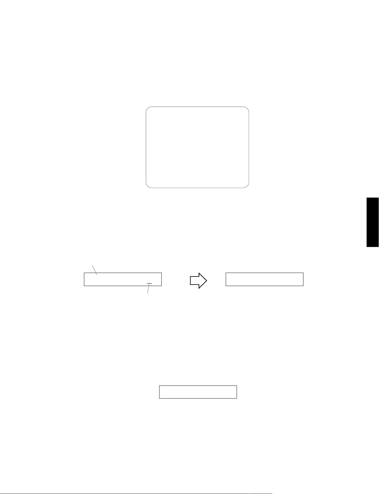
● Display provided when DIAG started
When the monitor is connected, DIAGNOSTIC MENU
appears on its screen as shown in the figure.
On the FL display of the main unit, an opening message
(including the version and the protection history) appears
for a few seconds followed by the diagnostic menu dis-
● ダイアグ起動時の表示
モニターを接続してある場合は、モニターの画面に図の
ようにダイアグメニューが表示されます。
本体FLディスプレイには、オープニング(プロテクショ
ン履歴/バージョン)が表示され、数秒後にダイアグメ
ニュー表示(1.ANALOGBYPASS)となります。
play (1. ANALOG BYPASS).
1.BYPASS
2.RAM THR
3.PRO LOGIC
4.SP SET
5.XCH INPUT
6.MIC CHECK
7.VFD CHECK
8.MAN,LTEST
9.PRESET
10.AD CHECK
11.VC STATUS
12.XM STATUS
13.IF STATUS
14.DSP BUS
15.SWFR C.OFF
16.PRT SET
17.PRT HIST.
18.SOFT SW
19.VER/SUM/P
20.TI BOOT
When there is no history of protection function: プロテクション履歴が無い場合:
RX-V757/DSP-AX757/DSP-AX757SE
RX-V657/HTR-5860
Openingmessage/オープニング表示
When there is no protection history
プロテクション履歴が無い場合
Afterafewseconds
NO PROTECT Z 1.ANALOG BYPAS
Version (1 alphabet)
バージョン(英1文字)
When there is a history of protection function:
The FL display appears as shown below depending on the
type of the protection function.
The protection function worked due to excessive current through the amplifier. Causes
could be a short at the speaker terminal or a
defect in the amplifier. The protection function activates immediately to turn off the
power, with no history display at turn-on, if
the amplifier is defective.
I PROTECT Z
DIAGmenudisplay/ダイアグメニュー表示
数秒後
プロテクション履歴がある場合:
プロテクションの種類によって下記の表示が現れます。
スピーカーをショートさせた時などが原因で、
プロテクションが働いたことを示します。
31
RX-V757/DSP-AX757/DSP-AX757SE
RX-V657/HTR-5860
The protection function worked due to a defect or overload in the power supply. If the
power is turned on with the abnormality unsolved, the protection function works in about
1 second to turn off the power.
The protection function worked due to a DC
voltage appearing at the speaker terminal.
A cause could be a defect in the amplifier. If
the power is turned on with the abnormality
unsolved, the protection function works in
about 3 seconds to turn off the power.
The protection function worked due to the
temperature limit being exceeded. Causes
could be poor ventillation or a defect related
to the thermal sensor. If the power is turned
on with the abnormality unsolved, the protection function works in about 1 second to
turn off the power.
PS PRT :000 Z
DC PRT :000 Z
TMP PRT:000 Z
電源電圧による原因で、プロテクションが
働いたことを示します。異常状態のままパ
ワーオンすると、約1秒後にプロテクション
が掛かり、電源が切れます。
アンプの故障でスピーカーに直流電圧が掛
かるなどが原因で、プロテクションが働い
たことを示します。異常状態のままパワー
オンすると、約3秒後にプロテクションが掛
かり、電源が切れます。
温度制限を越えた原因で、プロテクション
が働いたことを示します。異常状態のまま
パワーオンすると、約1秒後にプロテクショ
ンが掛かり、電源が切れます。
RX-V657/HTR-5860
For detection of each protection function (except I-PR OTECT)
RX-V757/DSP-AX757/DSP-AX757SE
, refer to DIAG MENU No.10 AD DATA (p.42).
● History of protection function
When the protection function has worked, its history is stored
in memory with a backup. Ev en if no abnormality is noted while
servicing the unit, an abnormality which has occurred previously can be defined as long as the backup data has been
stored.
The history of the protection function is cleared when DIAG is
cancelled by selecting PRESET RESERVED (Memory initialized) of DIAG menu No.9 or when the backup data is erased.
● Display during menu operation
During the DIAG operation, the menu list described in
the section of the startup screen appears on the monitor
screen and the function at work is indicated on the FL
indicator. The contents displayed during the function operation are described later in the “Details of DIAG menu”
section.
各プロクテクションの検出に関しては、後述のダイアグメ
ニューNo.10ADDATA(42ページ)を参照してください。
●プロテクションの履歴
プロテクションが働いた場合、履歴をバックアップして記憶していま
す。サービスのときに異常が認められなくても、バックアップが残って
いれば、お客様のところで起きた異常を区別できます。
ダイアグメニューNo.9 で PRESETRESERVED(メモリーの初期化)
を選んでダイアグを解除した場合、またはバックアップが消えた場合
に、プロテクションの履歴はクリアされます。
●メニュー動作中の表示
ダイアグ中、モニター画面には起動画面の項で説明し
たメニュー一覧が表示されます。本体のFLディスプ
レイには動作中の機能が表示されます。機能動作中の
表示内容については、後述の機能詳細で記述します。
32
RX-V757/DSP-AX757/DSP-AX757SE
RX-V657/HTR-5860
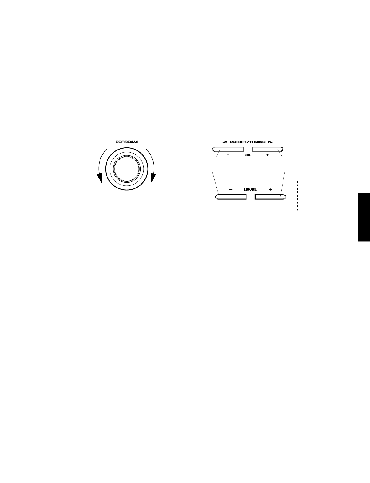
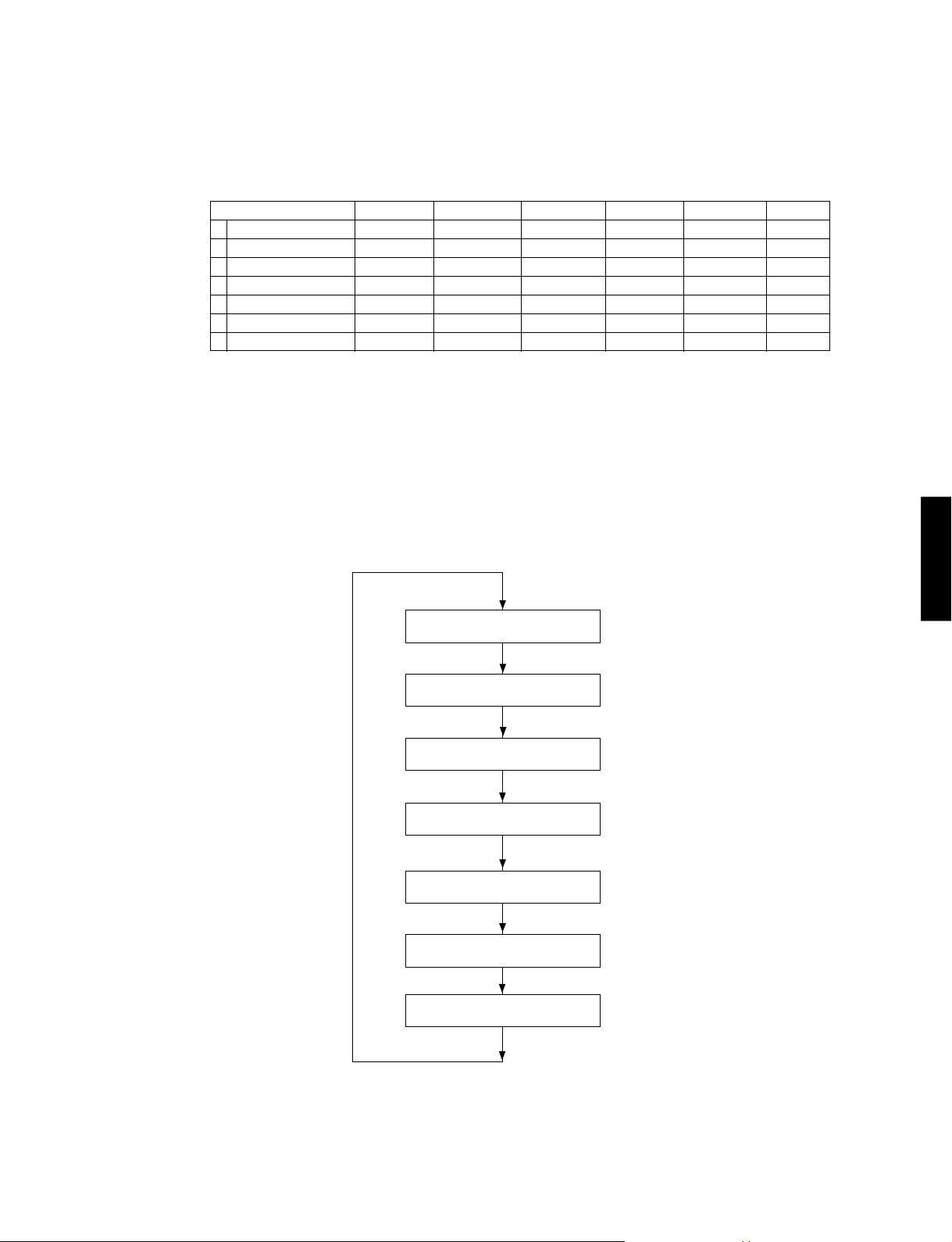
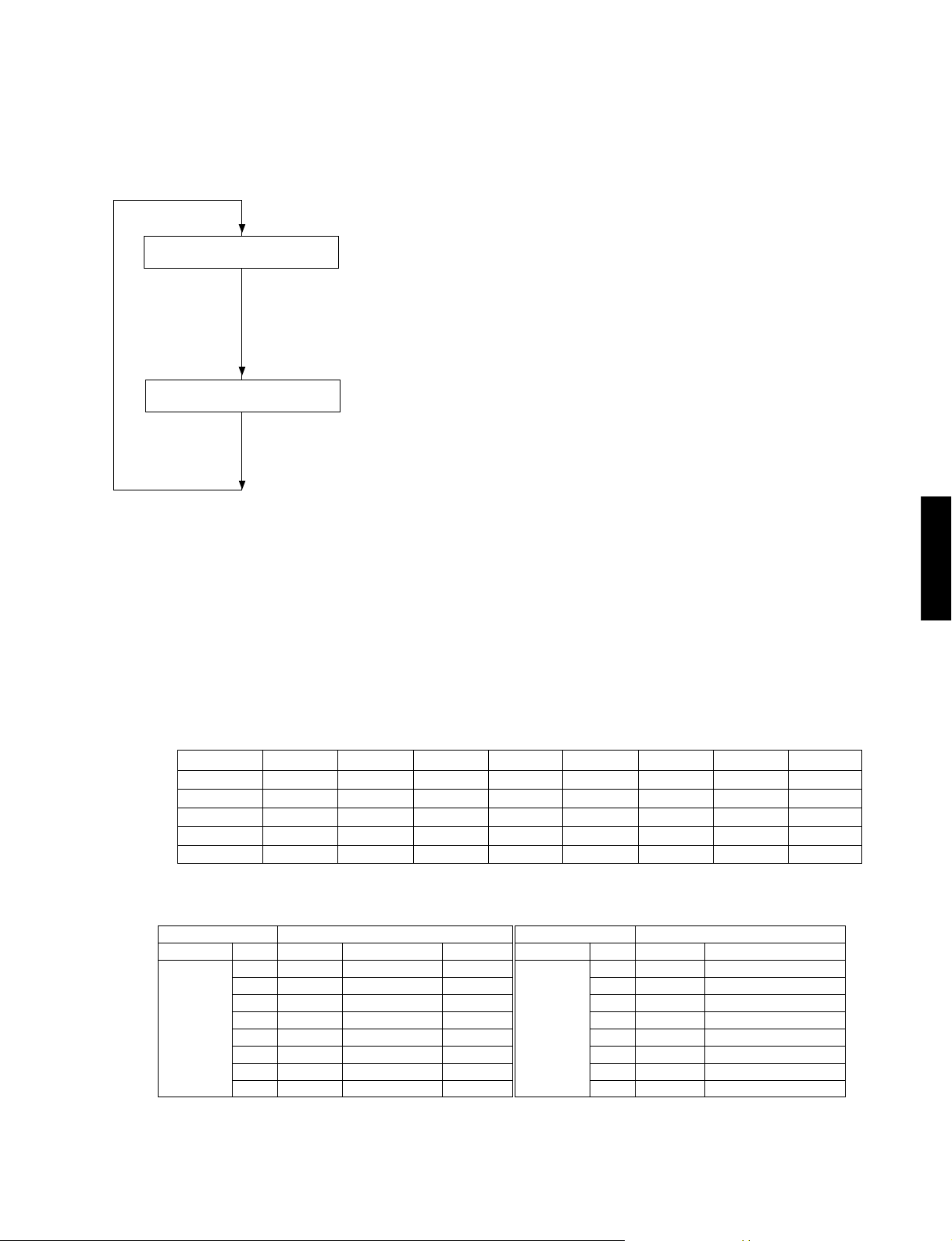
● Operation procedure of DIAG MENU and
SUB-MENU
There are 20 MENU items, each of which has some SUBMENU items.
DIAG menu selection
Select the menu using PROGRAM knob.
SUB-MENU selection
Select the sub-menu using w (Forward) and q (Reverse)
keys of PRESET/TUNING (LEVEL).
DIAG menu selection
ダイアグメニューの選択
Rev
erse F
逆送り
orward
順送り
● ダイアグメニューとサブメニューの操作
ダイアグにはNo.1〜20のメニューがあり、さらにいくつ
かのサブメニューがあります。
ダイアグメニューの選択
PROGRAMツマミで選択します。
サブメニューの選択
PRESET/TUNING w(順送り)、q(逆送り)キーで選択し
ます。
SUB-MENU selection
サブメニューの選択
Reverse
逆送り
DSP-AX757SE only
Forward
順送り
RX-V757/DSP-AX757/DSP-AX757SE
RX-V657/HTR-5860
● Functions in DIAG mode
In addition to the DIAG menu items, functions as listed
below are available.
• Input selection, Multi channel input
• Center/Surround/Surround Back/Sub-woofer level
adjustment
• Muting
• Speaker relay A/B
• Power on/off
• Master volume
* Functions related to the tuner and the set menu are not
available.
* It is possible to confirm Menu No.13 IF STATUS while
keeping the signal process (operation status) of each
DIAG menu by using the input mode key of the main
unit.
● Initial settings used to start DIAG
The following initial settings are used when starting
DIAG. When DIAG is canceled, these settings are
restored to those before starting DIAG.
• Master volume: -20dB
• Input: DVD (MULTI CHANNEL INPUT OFF)
• Effect level: 0dB
• Audio mute: OFF
• Speaker relay A/B: ON
• Speaker setting: LARGE / BASS OUT = SWFR
• DIAG menu: BYPASS (1. ANALOG BYPASS)
●ダイアグ中の機能
ダイアグメニューの他に、以下の機能が動作します。
・インプット切り換え、マルチチャンネルインプット
・センター、サラウンド、サラウンドバック、サブウー
ファーレベル調整
・ミューティング
・スピーカーリレーA/B
・パワーオン/オフ
・マスターボリューム
※チューナー関連、セットメニュー関連は機能しません。
※本体のINPUTMODEキーにより、各ダイアグメニューの
信号処理(動作状態)を維持したままメニューNo . 1 3
IFSTATUSの確認ができます。
●ダイアグ開始時の初期設定
ダイアグ開始時に以下のような設定になります。ダイア
グ解除時にはダイアグ開始前の状態に戻ります。
・マスターボリューム:‐20dB
・インプット:DVD(マルチチャンネルINPUTオフ)
・エフェクトレベル:0dB
・オーディオミュート:オフ
・スピーカーリレーA/B:オン
・スピーカー設定:LARGE/BASSOUT=SWFR
・ダイアグメニュー:BYPASS(1.ANALOGBYPASS)
33
RX-V757/DSP-AX757/DSP-AX757SE
RX-V657/HTR-5860
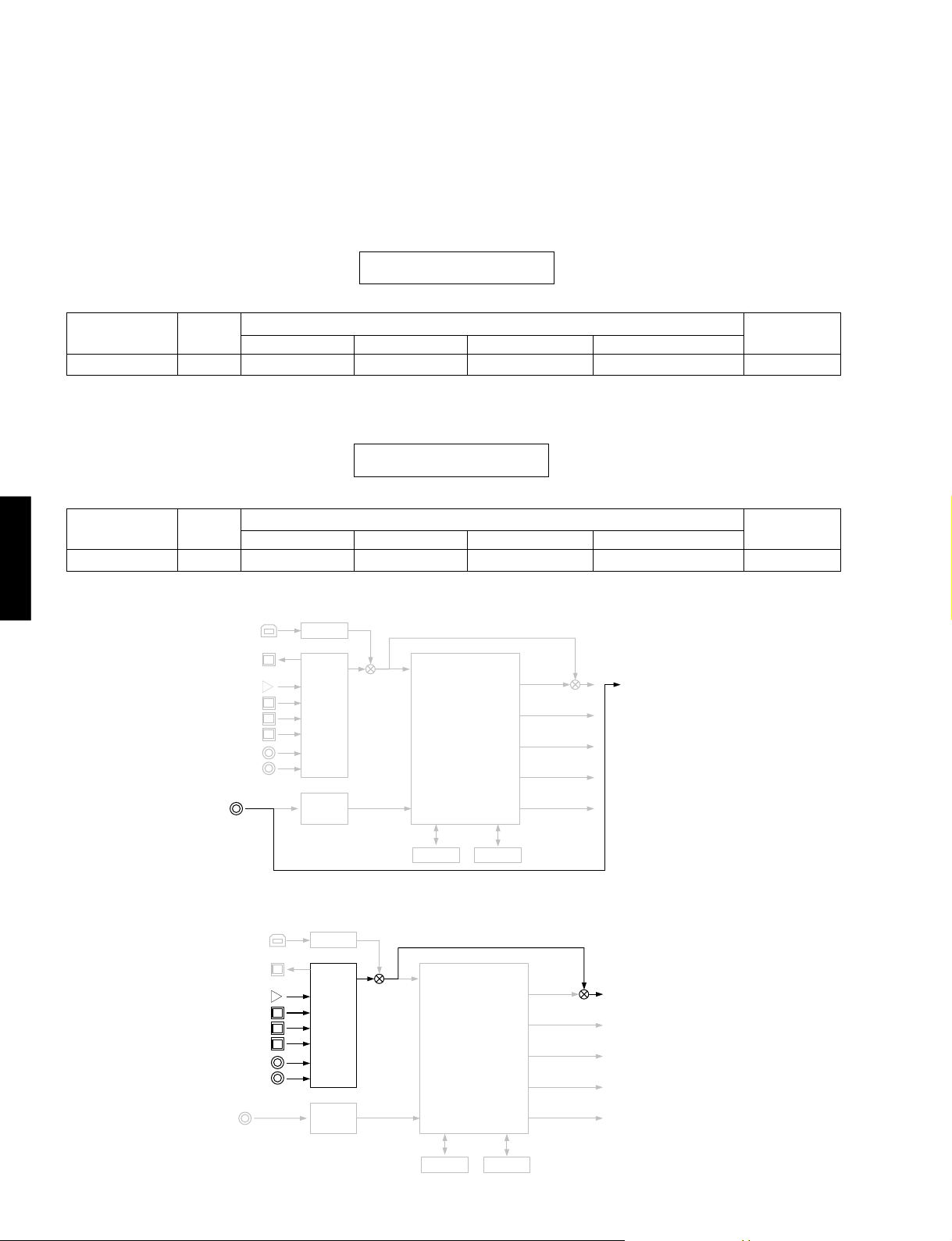
Details of DIAG menu
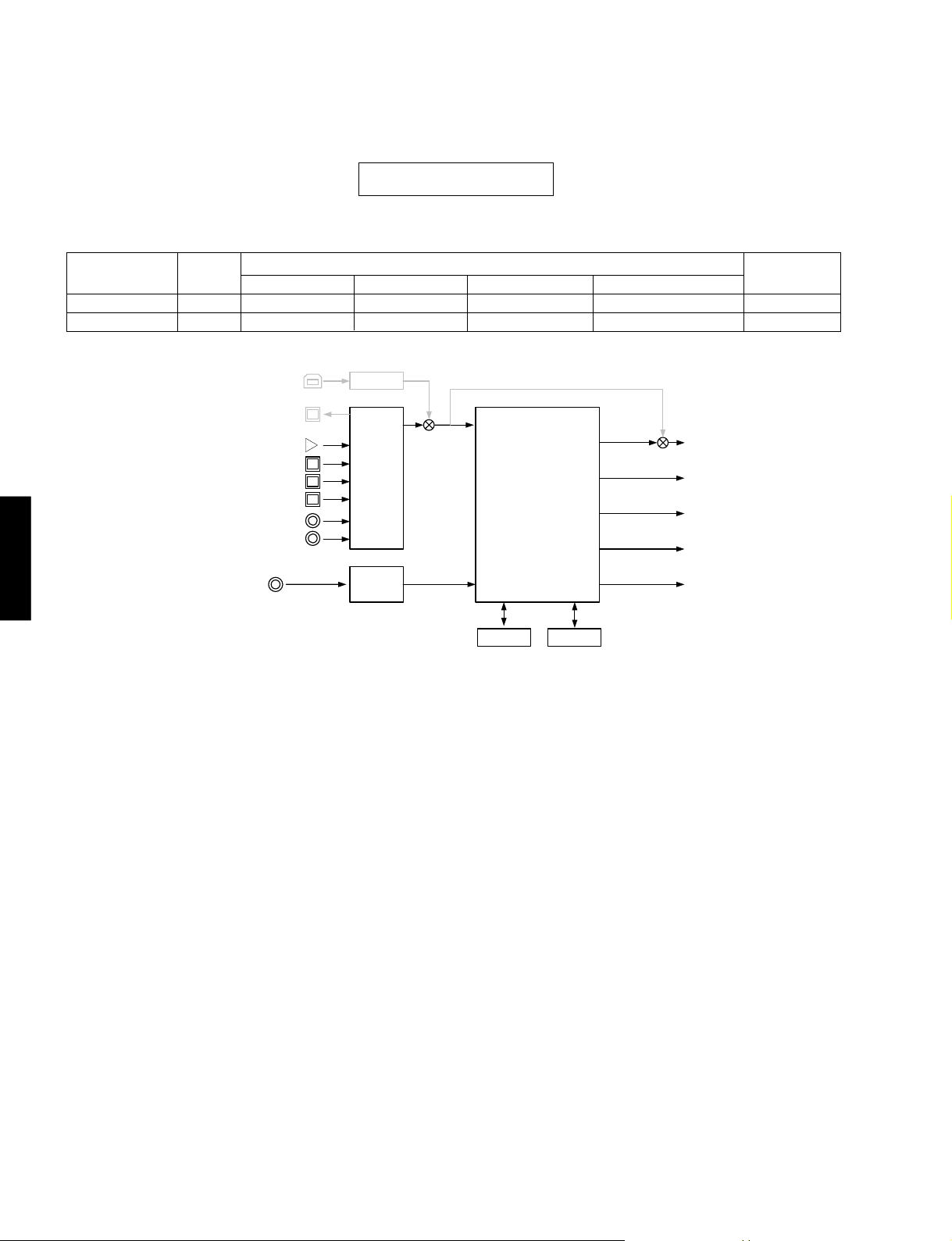
1. BYPASS
Using the sub-menu, it is possible to select analog bypass
output or DSP bypass output.
INPUT: DVD ANALOG
Input level
Both ch, -20 dBm
DSP BYPASS DSPBYPASS
INPUT: DVD ANALOG
Input level
Both ch, -20 dBm
RX-V657/HTR-5860
RX-V757/DSP-AX757/DSP-AX757SE
ANALOG BYPASS
Volume
+6.5 dB
Volume
+6.5 dB
(U, C models)
FRONT L/R
+13.0 dBm
FRONT L/R
+13.0 dBm
XMDT
ダイアグメニュー詳細
1.BYPASS
サブメニューによりANALOGBYPASS/DSPBYPASSが選
択可能です。
ANALOGBYPASSANALOG BYPASS
1.ANALOG BYPAS
SPEAKERS OUT (1KHz)
CENTER
- ∞
1.DSP BYPASS
SPEAKERS OUT (1KHz)
CENTER
- ∞
SURROUND L/R
SURROUND L/R
- ∞
- ∞
SURROUND BACK L/R
- ∞
SURROUND BACK L/R
- ∞
SUBWOOFER
(50 Hz)
- ∞
SUBWOOFER
(50 Hz)
- ∞
DSP BYPASS
(U, C models)
DIR
LC89057
A/D
AK4628
XMDT
DIR
LC89057
A/D
AK4628
DSP
( DECODE)
(POST PROCESSING)
TI DA60Y
DRAM
(POST PROCESSING)
ROM
DSP
( DECODE)
TI DA60Y
FL / FR
PL / PR
C / SW
SL / SR
SBL/ S BR
FL / FR
PL / PR
C / SW
SL / SR
SBL/ S BR
34
DRAM
ROM
(Shaded items not used in this example)
RX-V757/DSP-AX757/DSP-AX757SE
RX-V657/HTR-5860
2. RAM THROUGH
Using the sub-menu, it is possible to select margin output or
full-bit output.
RAM MARGIN
Following head margin is reserved.
FRONT
+15.0 dB
CENTER
+13.5 dB
SURROUND
+9.0 dB
2.RAM MARGIN
INPUT: DVD ANALOG
Input level
Both ch, -20 dBm
RAM FULL BIT
No head margin is reserved except SW.
FRONT
0 dB
Volume
+6.5 dB
FRONT L/R
+13.0 dBm
CENTER
0 dB
CENTER
+13.0 dBm
SURROUND
0 dB
2.RAMTHROUGH
サブメニューによりMARGIN/FullBitが選択可能です。
RAMMARGIN
以下のヘッドマージンを取ります。
SURROUND BACK
+7.5 dB
SPEAKERS OUT (1KHz)
SURROUND L/R
+13.0 dBm
RAMFULLBIT
SW以外のヘッドマージンを取りません。
SURROUND BACK
0 dB
SUBWOOFER
+21 dB
SURROUND BACK L/R
+13.0 dBm
SUBWOOFER
+21 dB
PRESENCE
+15.0 dB
SUBWOOFER
PRESENCE
0 dB
(50 Hz)
+ 0.5 dBm
RX-V757/DSP-AX757/DSP-AX757SE
RX-V657/HTR-5860
INPUT: DVD ANALOG
Input level
Both ch, -20 dBm
Volume
+6.5 dB
FRONT L/R
+13.0 dBm
(U, C models)
2.RAM FULL BIT
SPEAKERS OUT (1KHz)
CENTER
+13.0 dBm
XMDT
DIR
LC89057
A/D
AK4628
SURROUND L/R
(POST PROCESSING)
+13.0 dBm
DSP
( DECODE)
TI DA60Y
DRAM
SURROUND BACK L/R
+13.0 dBm
FL / FR
PL / PR
C / SW
SL / SR
SBL/ S BR
ROM
SUBWOOFER
(50 Hz)
+ 0.5 dBm
(Shaded items not used in this example)
When input source is stereo, signal is assigned as below.
2ch 信号入力時、以下のように信号を振り分けて出力します。
Front L → Center / Surround L / Surround Back L, R / Presence L
Front R → Surround R / Presence R
Front L + 10 dB → SWFR
35
RX-V757/DSP-AX757/DSP-AX757SE
RX-V657/HTR-5860
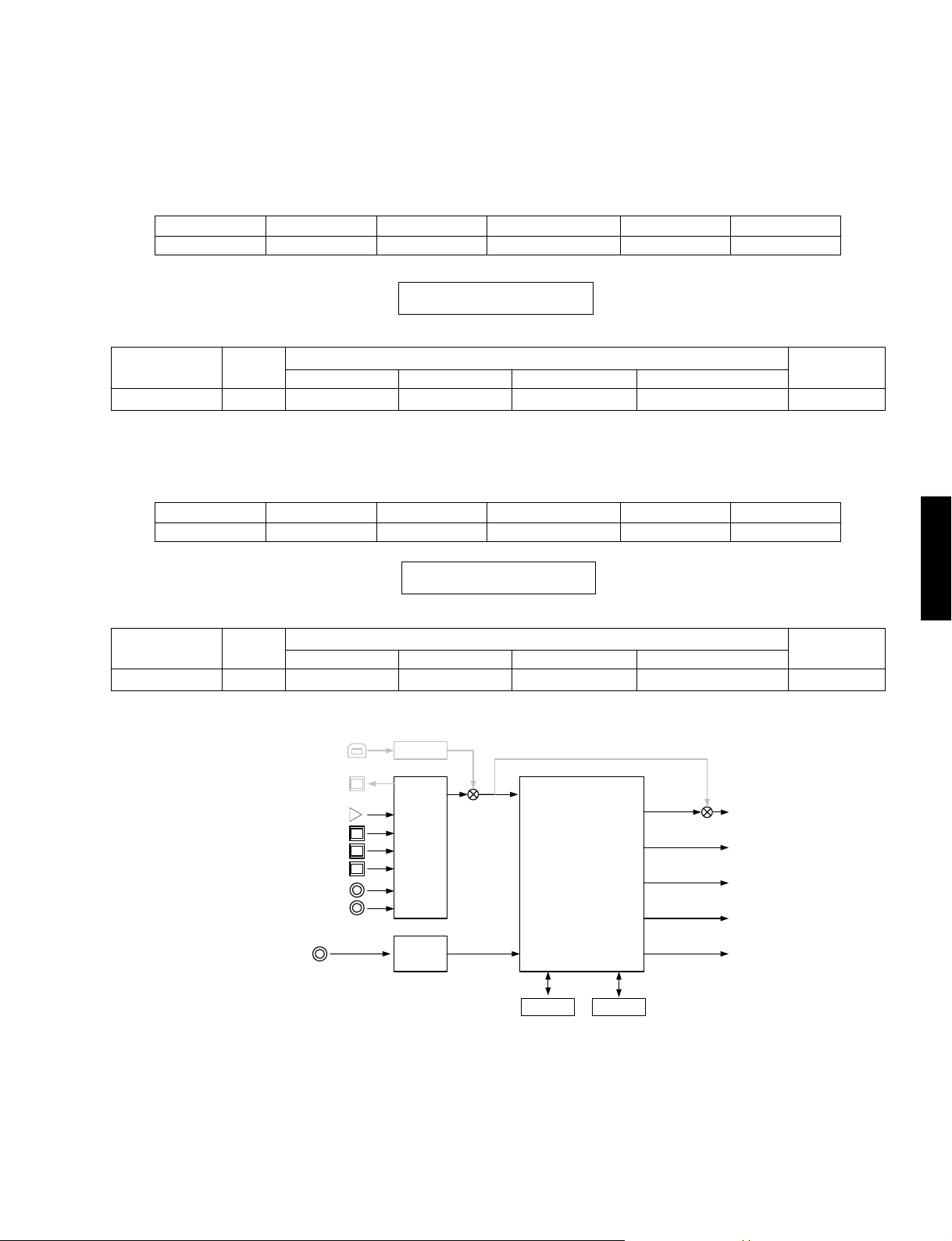
3. PRO LOGIC
• Dolby PRO LOGIC is applied to input stereo source.
3.PRO LOGIC
INPUT: DVD ANALOG
Input level
Each ch, -20 dBm
Both ch, -20 dBm
Volume
+6.5 dB
+6.5 dB
FRONT L/R
+13.0 dBm
(U, C models)
- ∞
CENTER
+13.0 dBm
XMDT
DIR
LC89057
3.PROLOGIC
・入力 2ch 信号に DolbyPROLOGIC 処理を行います。
SPEAKERS OUT (1KHz)
SURROUND L/R
- ∞
(POST PROCESSING)
- ∞
- ∞
DSP
( DECODE)
TI DA6 0 Y
SURROUND BACK L/R
- ∞
- ∞
FL / FR
PL / PR
C / SW
SL / SR
SUBWOOFER
(50 Hz)
- ∞
- ∞
RX-V657/HTR-5860
RX-V757/DSP-AX757/DSP-AX757SE
A/D
AK4628
DRAM
ROM
(Shaded items not used in this example)
SBL / SBR
36
RX-V757/DSP-AX757/DSP-AX757SE
RX-V657/HTR-5860
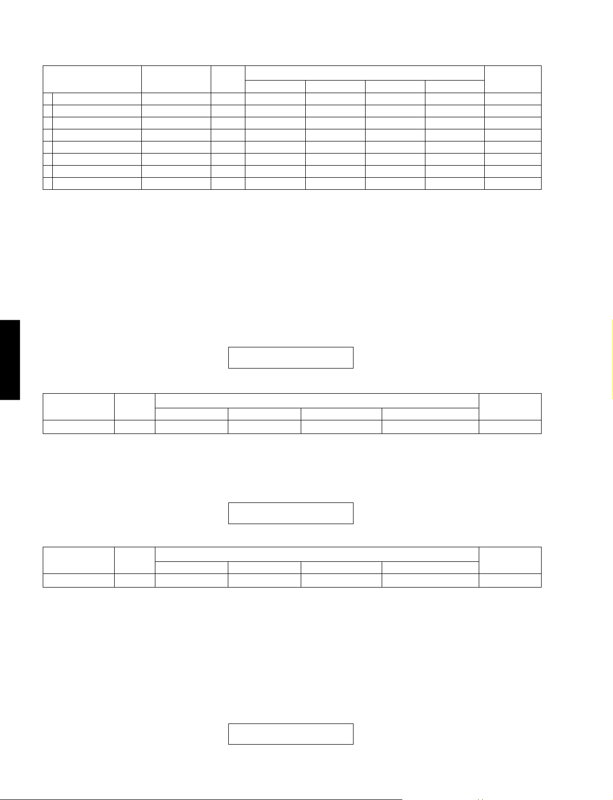
4. SPEAKERS SET
The analog switch settings for each sub-menu are as sho wn
in the table below.
•“F mix” is Mixing Presence to Front.
Sub-menu FRONT CENTER SUR. SUR.B LFE F mix
1 FRNT: SML 0 dB SMALL LARGE LARGE LARGE SWFR No
2 CENTER: NONE LARGE NONE LARGE LARGE SWFR No
3 LFE/B: FRNT LARGE SMALL SMALL SMALL FRONT No
4 Pre Mix: 5ch LARGE LARGE LARGE LARGE SWFR Yes
5 Front GAIN 1 LARGE LARGE LARGE LARGE SWFR Yes
6 Front GAIN 2 LARGE LARGE LARGE LARGE SWFR Yes
7 Znone 2 Amp ON LARGE LARGE LARGE ZONE 2 SWFR No
LARGE: This mode is used with a speaker with high bass repro-
duction performance (a large unit). Full bandwidth signals
are output.
SMALL: This mode is used with a speaker with low bass reproduc-
tion performance (a small unit). The signals of 80Hz or
less are mixed into the channel specified by LFE/BASS.
NONE: This mode is used with no center speaker.
The center content is reduced by 3dB and distributed to
FRONT L/R.
4.SPEAKERSSET
各サブメニューにおけるアナログスイッチの設定は以下の
通りです。
・FmixはPresenceをFrontmixするかどうかです。
LARGE: 低音再生能力の高い(ユニットの大きい)スピーカーを
使用するモードです。全帯域が出力されます。
SMALL:低音再生能力の低い(ユニットの小さい)スピーカーを
使用するモードです。80Hz以下がLFE/BASSで指定し
たチャンネルにミックスされます。
NONE:
スピーカーを使用しないモードです。センター成分は-3dB
されて、FRONTL/Rに振り分けられます。
RX-V757/DSP-AX757/DSP-AX757SE
RX-V657/HTR-5860
4.FRNT:SML 0dB
4.CENTER:NONE
4.LFE/B:FRNT
4.Pres Mix:5ch
4.Front GAIN 1
4.Front GAIN 2
4.Zone2 Amp ON
37
RX-V757/DSP-AX757/DSP-AX757SE
RX-V657/HTR-5860
INPUT: DVD ANALOG
Sub-menu
1 FRONT: SML 0dB
2 CENTER: NONE
3 LFE/B: FRNT (1kHz)
4 LFE/B: FRNT (50Hz)
5 Pres Mix 5ch
6 Front GAIN 1
7 Front GAIN 2
8 Zone 2 Amp ON
Input level
Both ch, -20 dBm
Both ch, -20 dBm
Both ch, -20 dBm
Both ch, -20 dBm
Both ch, -20 dBm
Both ch, -20 dBm
Both ch, -20 dBm
Both ch, -20 dBm
Volume
+6.5 dB
+6.5 dB
+6.5 dB
+6.5 dB
+6.5 dB
+6.5 dB
+6.5 dB
+6.5 dB
FRONT L/R
+13.0 dBm
+9.5 dBm
- ∞
+13.0 dBm
+18.5 dBm
+13.0 dBm
+18.5 dBm
+13.0 dBm
SPEAKERS OUT (1KHz)
CENTER
+ 13.0 dBm
- ∞
+13.0 dBm
- ∞
+13.0 dBm
+13.0 dBm
+13.0 dBm
+13.0 dBm
SUR L/R
+13.0 dBm
+13.0 dBm
+13.0 dBm
- ∞
+18.5 dBm
+13.0 dBm
+13.0 dBm
+13.0 dBm
SUR.B L/R
+13.0 dBm
+13.0 dBm
+13.0 dBm
- ∞
+13.0 dBm
+13.0 dBm
+13.0 dBm
- ∞
SUBWOOFER
(50 Hz)
+3.5 dBm
- 0.5 dBm
- ∞
- 0.5 dBm
- 0.5 dBm
- 0.5 dBm
- 0.5 dBm
- 0.5 dBm
5. XCH INPUT
The signal input through the multi ch input is output.
The speaker impedance can be selected.
RX-V657/HTR-5860
RX-V757/DSP-AX757/DSP-AX757SE
INPUT: MULTI CH INPUT
Input level
Both ch, -20 dBm
Volume
+6.5 dB
XCH INPUT_8 (ohms)
FRONT L/R
+13.0 dBm
5.XCHINPUT
マルチCH入力された信号が出力されます。
6オーム,8オームが選択されます。
XCHINPUT6(ohms)XCH INPUT_6 (ohms)
5.XCH INPUT_6
SPEAKERS OUT (1KHz)
CENTER
+13.0 dBm
SURROUND L/R
+13.0 dBm
XCHINPUT8(ohms)
5.XCH INPUT_8
SURROUND BACK L/R
+13.0 dBm
SUBWOOFER
(50 Hz)
- 8.5 dBm
INPUT: MULTI CH INPUT
Input level
Both ch, -20 dBm
Volume
+6.5 dB
FRONT L/R
+13.0 dBm
CENTER
+13.0 dBm
6. MIC CHECK
The signal input through the microphone is output via A/D-D/A.
“dB” display function is not mounted.
6.MIC CHK --dB
38
SPEAKERS OUT (1KHz)
SURROUND L/R
+13.0 dBm
6.MICCHECK
マイク入力された信号をA/D-D/A経由で出力します。
dB表示は機能しません。
SURROUND BACK L/R
+13.0 dBm
SUBWOOFER
(50 Hz)
- 8.5 dBm
RX-V757/DSP-AX757/DSP-AX757SE
RX-V657/HTR-5860
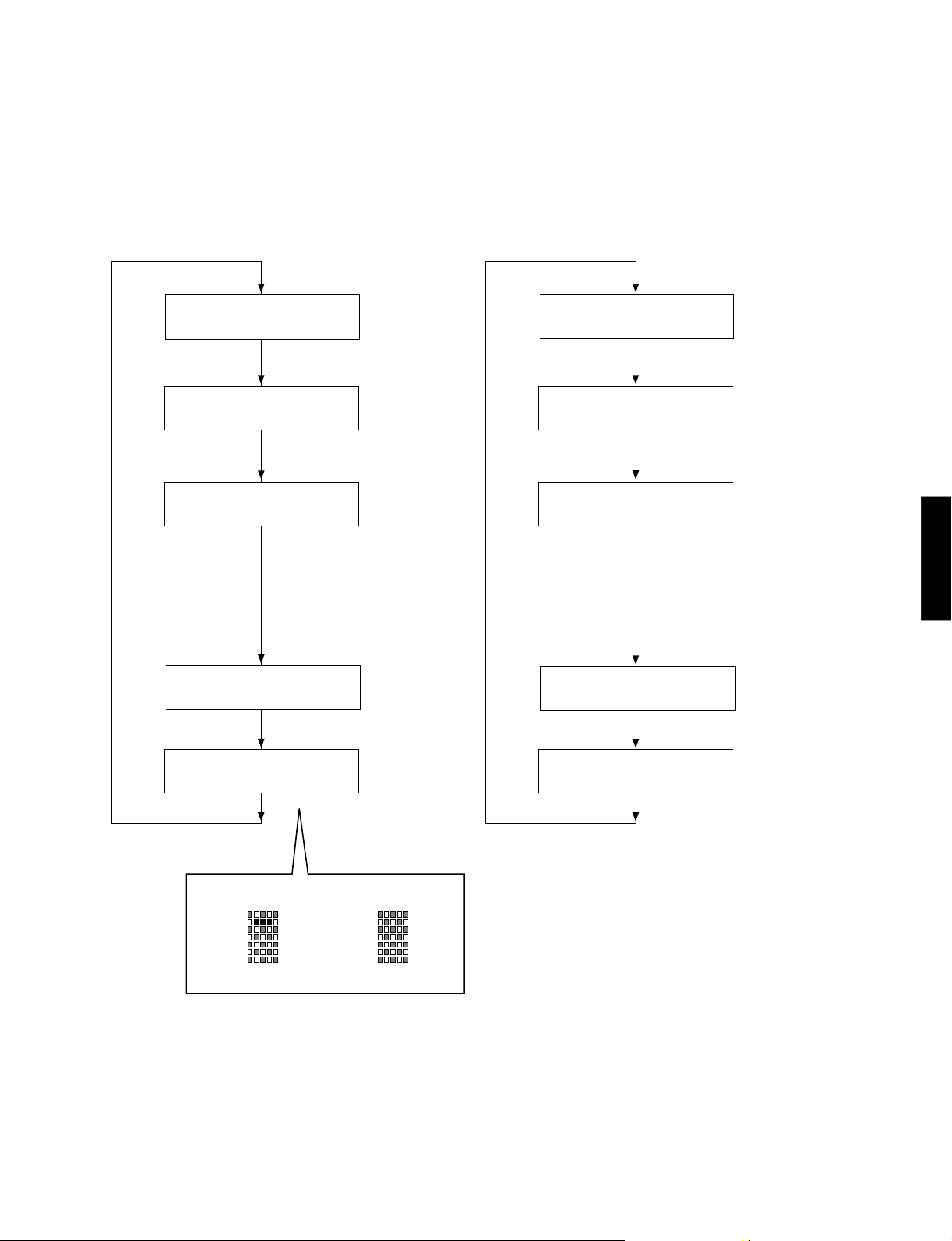
7. VFD CHECK
• This program is used to check the FL display section
and video control section. The display condition varies
as shown below according to the sub-menu operation.
• The signal route is STRAIGHT.
FL
Initial display /初期表示
All segments OFF /
全セグメント消灯
All segments ON (dimmer 100%) /
全セグメント点灯(ディマー 100%)
7.VFDCHECK
・FL表示部と映像制御部のチェックプログラムです。サブ
メニュー操作により、表示状態が以下のように変わりま
す。
・信号処理はSTRAIGHTです。
OSD
Initial display /初期表示
OSD OFF /
OSD消灯
All characters ON /
キャラクタパターン
The 128 pictographs for checking the
OSD driver are used for the video
signal output display.
映像出力にOSDドライバー確認用128絵
文字表示が出ます。
RX-V757/DSP-AX757/DSP-AX757SE
RX-V657/HTR-5860
All segments ON (dimmer 50%) /
全セグメント点灯(ディマー 50%)
Lighting of segments in lattice /
セグメント格子状点灯
Lighting in lattice / 格子状点灯
Normal / 正常Short / ショート
Segment conditions of the FL driver and the FL tube are
checked by turning ON and OFF all segments. Next, the
operation of the FL driver is checked by using the dimmer
control. Then a short between segments next to each other
is checked by turning ON and OFF all segments alternately
(in lattice). (In the above example, the segments in the second row from the top are shorted.)
OSD OFF /
OSD消灯
OSD OFF /
OSD消灯
全セグメント消灯・全セグメント点灯によりFLドライバー、
FL管のセグメントの不良を確認します。
次に、ディマーコントロールによってFLドライバーの動作
チェックを行います。
さらに全セグメントを交互(格子状)に点灯/消灯することで、
隣り合うセグメントのショートをチェックします。
39

RX-V757/DSP-AX757/DSP-AX757SE
RX-V657/HTR-5860
8. MANUAL TEST
The test noise based THX is output to the channel specified
by the sub-menu from the DSP.
8.TEST ALL
8.TEST FRNT L
8.TEST CENTER
8.TEST FRNT R
8.MANUALTEST
DSPからサブメニューで指定したチャンネルへTHX準拠
のテストノイズを出力します。
RX-V657/HTR-5860
RX-V757/DSP-AX757/DSP-AX757SE
8.TEST SURR R
8.TEST SB R
8.TEST SB L
8.TEST SURR L
8.TEST PRES L
8.TEST PRES R
40
8.TEST LFE
RX-V757/DSP-AX757/DSP-AX757SE
RX-V657/HTR-5860
9. FACTORY PRESET
This menu is used to reserve/inhibit initialization of the backup RAM (Parameters and set menu contents, etc. of the
sound field program).
PRESET INHIBIT (Initialization inhibited) / PRESETINHIBIT(初期化禁止)
RAM initialization is not executed. Select this sub-menu to protect the values set by
9.PRESET INHI
9.PRESET RSRV
the user.
Note: The protection history will not be erased using PRESET INHIBIT.
RAMの初期化は行われません。ユーザーの設定値を保護するときは、こちらを選択
してください。
PRESET RESERVED (Initialization reserved) / PRESETRESERVED(初期化予約)
Initialization of the back-up RAM is reserved. (Actually, initialization is executed the
next time that the power is turned on.) Select this sub-menu to reset to the original
factory settings or to reset the RAM. Use PRESET RESERVED to erase the protection history.
バックアップRAMの初期化が予約されます。(実際に初期化されるのは、次回の電
源投入時です。)工場出荷時やRAMをリセットしたいときは、こちらを選択してくだ
さい。
9.FACTORYPRESET
バックアップ用RA M(音場プログラムのパラメー ターや
セットメニュー内容等)の初期化を予約/禁止します。
RX-V757/DSP-AX757/DSP-AX757SE
RX-V657/HTR-5860
CAUTION: Before setting to the PRESET RESER VED, write down
the existing preset memory
content of the Tuner in a table as shown below. (This is because setting to the PRESET RESERVED will cause ALL user
memory contents to be erased.)
Preset group
A
B
C
D
E
● PRESET STATIONS / プリセット局
STATION FM FACTORY PRESET DATA (MHz)
PAGE NO. U, C R, T, K, A, B, G, L J
A/C/E 4 98.1 98.10 86.0
P1 P2 P3 P4 P5 P6 P7 P8
1 87.5 87.50 76.0
2 90.1 90.10 83.0
3 95.1 95.10 84.0
5 107.9 108.00 90.0
6 88.1 88.10 78.0
7 106.1 106.10 88.0
8 107.9 108.00 82.1
注意:PRESETRESERVEDを選んで初期化をする前に、チュー
ナーのユーザーメモリー内容を下表に書き写してください。(初期
化をすると、ユーザーメモリーの内容は消えてしまいます。)
STATION AM FACTORY PRESET DATA (kHz)
PAGE NO. U, C, R, T, K A, B, G, L, J
1 630 630
2 1080 1080
3 1440 1440
B/D 4 530 531
5 1710 1611
6 900 900
7 1350 1350
8 1400 1404
41
 Loading...