

Yamaha RX-V596RDS User Manual

RX-V596RDS
Natural Sound AV Receiver
Ampli-tuner audio-vidéo
G B
OWNER’S MANUAL
MODE D’EMPLOI
BEDIENUNGSANLEITUNG
BRUKSANVISNING
MANUALE DI ISTRUZIONI
MANUAL DE INSTRUCCIONES
GEBRUIKSAANWIJZING

CAUTION: READ THIS BEFORE OPERATING YOUR UNIT.
1. To assure the finest performance, please read this
manual carefully. Keep it in a safe place for future
reference.
2. Install this unit in a cool, dry, clean place — away
from windows, heat sources, sources of excessive
vibration, dust, moisture and cold. Avoid sources of
humming (transformers, motors). To prevent fire or
electrical shock, do not expose the unit to rain or
water.
3. Never open the cabinet. If something drops into the
unit, contact your dealer.
4. Do not use force on switches, controls or connection
cables. When moving the unit, first disconnect the
power cord and then the cables connected to other
component. Never pull the cables themselves.
5. The openings on the cover assure proper ventilation
of the unit. If these openings are obstructed, the
temperature inside the unit will rise rapidly.
Therefore, avoid placing objects against these
openings, and install the unit in a well-ventilated area
to prevent fire and damage.
Be sure to allow a space of at least 20 cm behind,
20 cm on both sides and 30 cm above the top panel
of the unit to prevent fire and damage.
6. The voltage used must be the same as that specified
on this unit. Using this unit with a higher voltage than
specified is dangerous and may result in fire or other
accidents. YAMAHA will not be held responsible for
any damage resulting from the use of this unit with a
voltage other than that specified.
7. Digital signals generated by this unit may interfere
with other component such as tuners, receivers and
TVs. Move this unit farther away from such
component if interference is observed.
8. Always set VOLUME to the “m” position before
starting the audio source play. Increase the volume
gradually to an appropriate level after playback has
been started.
9. Do not attempt to clean the unit with chemical
solvents; this might damage the finish. Use a clean,
dry cloth.
10. Be sure to read the “TROUBLESHOOTING” section
regarding common operating errors before
concluding that the unit is faulty.
11. When not planning to use this unit for a long period
of time (e.g., a vacation), disconnect the AC power
cord from the wall outlet.
12. To prevent lightning damage, disconnect the AC
power cord and disconnect the antenna cable when
there is an electrical storm.
13. Grounding or polarization — Precautions should be
taken so that the grounding or polarization of the unit
is not defeated.
14. AC outlet — Do not connect audio component to the
AC outlet on the rear panel if that component
requires more power than the outlet is rated to
provide.
This unit is not disconnected from the AC power source
as long as it is connected to the wall outlet, even if this
unit itself is turned off. This state is called the standby
mode. In this state, this unit is designed to consume a
very small quantity of power.
■ For U.K. customers
If the socket outlets in the home are not suitable for the plug
supplied with this appliance, it should be cut off and an
appropriate 3 pin plug fitted. For details, refer to the
instructions described below.
Note
• The plug severed from the mains lead must be destroyed, as a
plug with bared flexible cord is hazardous if engaged in a live
socket outlet.
■ Special Instructions for U.K. Model
IMPORTANT
THE WIRES IN MAINS LEAD ARE COLOURED IN
ACCORDANCE WITH THE FOLLOWING CODE:
Blue: NEUTRAL
Brown: LIVE
As the colours of the wires in the mains lead of this
apparatus may not correspond with the coloured
markings identifying the terminals in your plug, proceed
as follows:
The wire which is coloured BLUE must be connected to
the terminal which is marked with the letter N or
coloured BLACK. The wire which is coloured BROWN
must be connected to the terminal which is marked with
the letter L or coloured RED.
Making sure that neither core is connected to the earth
terminal of the three pin plug.
CAUTION

INTRODUCTION
FEATURES
5-Channel Power Amplification
◆ Minimum RMS Output
(0.06% THD, 20 Hz – 20 kHz)
Main: 70 W +70 W (8 Ω)
Center: 70 W (8 Ω)
Rear: 70 W + 70 W (8 Ω)
Multi-Mode Digital Sound Field
Processing
◆ Digital Sound Field Processor (DSP)
◆ Dolby Pro Logic Decoder
◆ Dolby Digital Decoder
◆ DTS Decoder
◆ CINEMA DSP: Combination of YAMAHA DSP
Technology and Dolby Pro Logic, Dolby Digital or
DTS
Sophisticated FM/AM Tuner
◆ 40-Station Random Access Preset Tuning
◆ Automatic Preset Tuning
◆ Preset Station Shifting Capability (Preset Editing)
◆ Multi-Functions for RDS Broadcast Reception
Other Features
◆ 96-kHz/24-bit D/A Converter
◆ “SET MENU” which Provides You with 12 Items
for Optimizing This Unit for Your Audio/Video
System
◆ Test Tone Generator for Easier Speaker Balance
Adjustment
◆ 6-Channel External Decoder Input for Other Future
Formats
◆ S Video Signal Input/Output Capability
◆ 3 Optical/2 Coaxial Digital Signal Input Terminals
◆ SLEEP Timer
◆ Remote Control with Preset Manufacturer Codes
CONTENTS
INTRODUCTION
FEATURES .................................................................. 1
CONTENTS ................................................................. 1
GETTING STARTED ................................................. 2
CONTROLS AND FUNCTIONS ............................... 4
PREPARATION
SPEAKER SETUP....................................................... 9
CONNECTIONS........................................................ 10
ADJUSTING THE SPEAKER BALANCE ............ 19
BASIC OPERATION
PLA YING A SOURCE .............................................. 21
DIGITAL SOUND FIELD PROCESSOR (DSP)
EFFECT .................................................................. 25
TUNING ..................................................................... 27
RECEIVING RDS STATIONS................................. 31
RECORDING A SOURCE ON TAPE, MD OR
VIDEO CASSETTE ............................................... 34
ADVANCED OPERATION
SOUND FIELD PROGRAM .................................... 35
SET MENU................................................................. 38
DELAY TIME AND SPEAKER
OUTPUT LEVELS ................................................. 42
SLEEP TIMER .......................................................... 44
PRESET REMOTE CONTROL .............................. 45
INTRODUCTION PREP ARA TION
ADV ANCED OPERA
TION APPENDIX
Manufactured under license from Dolby
Laboratories. “Dolby”, “Pro Logic” and the
double-D symbol are trademarks of Dolby
Laboratories. Confidential Unpublished Works.
©1992 – 1997 Dolby Laboratories, Inc. All
rights reserved.
Manufactured under license from Digital Theater Systems, Inc.
US Pat. No. 5,451,942 and other world-wide patents issued and
pending. “DTS”, “DTS Digital Surround”, are trademarks of
Digital Theater Systems, Inc. Copyright 1996 Digital Theater
Systems, Inc. All Rights Reserved.
APPENDIX
TROUBLESHOOTING ............................................ 53
SPECIFICATIONS.................................................... 57
GLOSSARY................................................................ 58
INDEX ........................................................................ 59
y indicates a tip for your operation.
• When buttons on this unit and the remote control are
noted together in this Owner’s Manual, these button
names are in principle noted in the order of “button name
(remote control button name)”.
EnglishBASIC OPERATION
1
GETTING STARTED
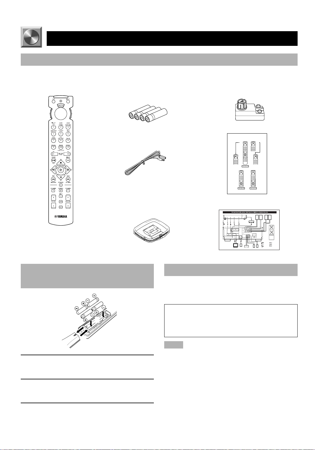
Checking the Package Contents
Check that the following items are included in your package.
Remote control Batteries (AAA, R03, UM-4 type) 75-ohm/300-ohm antenna adapter
Indoor FM antenna
AM loop antenna
(U.K. model only)
Quick reference card
Quick Reference Card
Connection guide
Battery Installation in the Remote
Control
2
1
3
1 Turn the remote control over and slide the
battery compartment cover in the direction of
the arrow.
2 Insert the batteries (AAA, R03 or UM-4 type)
according the polarity markings on the inside
of the battery compartment.
3 Close the battery compartment cover.
2
Battery Replacement
If the remote control operates only when it is close to the
unit, the batteries are weak. Replace all the batteries with
new ones.
Be sure to replace the batteries within about two minutes.
If it takes longer than two minutes, the codes set for the
remote control will return to the factory settings. (Refer
to pages 45 to 52 about the remote control.)
Notes
• Use only AAA, R03 or UM-4 batteries for replacement.
• Be sure the battery polarity is correct. (See the illustration inside
the battery compartment.)
• Remove the batteries if the remote control will not be used for an
extended period of time.
• If the batteries have leaked, dispose of them immediately. Avoid
touching the leaked material or letting it come into contact with
clothing, etc. Clean the battery compartment thoroughly before
installing new batteries.
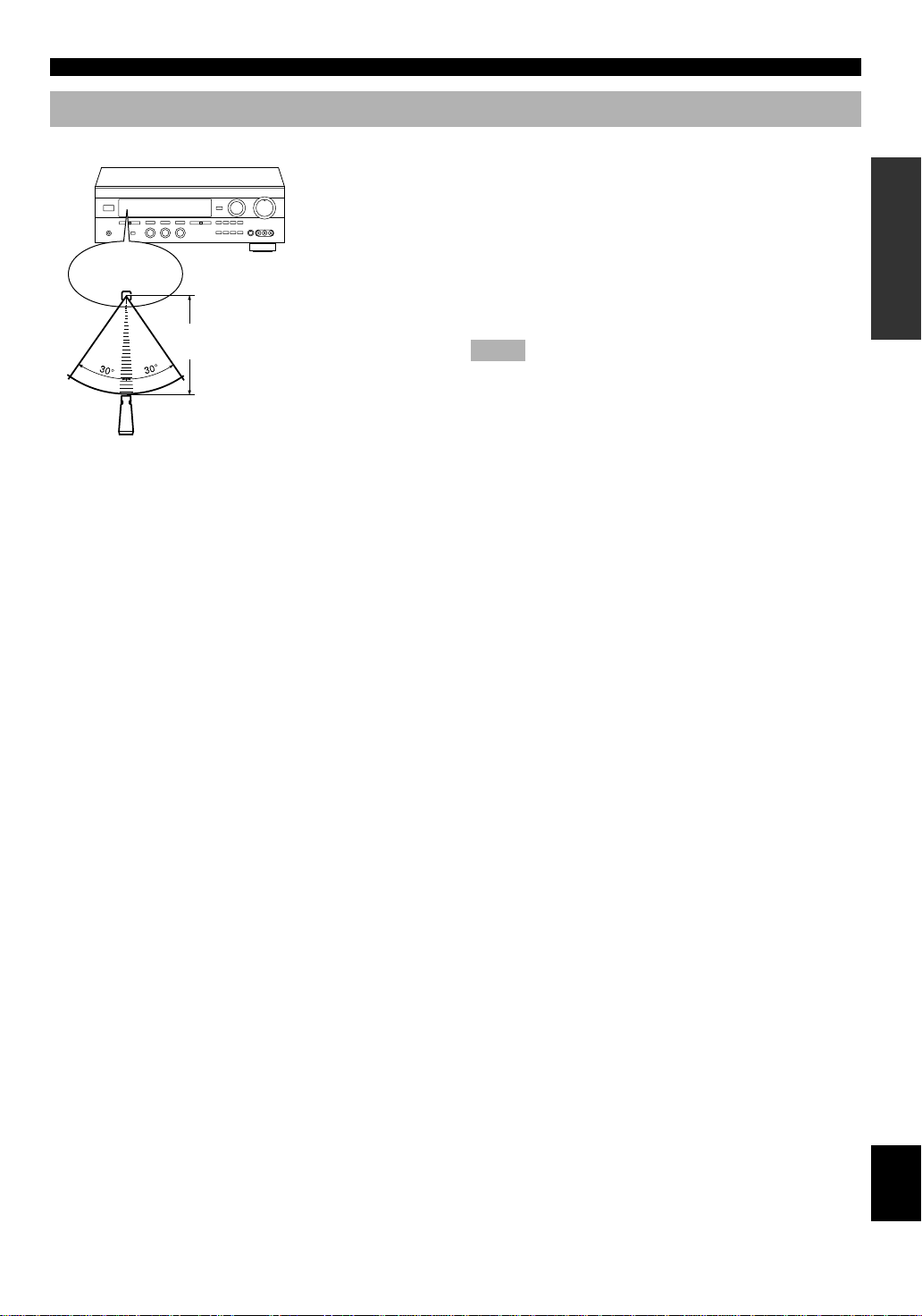
Using the Remote Control
Remote control
sensor
Within approximately 6 m
(20 feet)
GETTING STARTED
The remote control transmits a directional infrared beam. Be
sure to aim the remote control directly at the infrared sensor
during operation. When the sensor is covered or there is a
large object between the remote control and the sensor, the
sensor cannot receive signals. The sensor may not be able to
receive signals properly when it is exposed to direct sunlight
or a strong artificial light (such as a fluorescent or strobe
light). In this case, change the direction of the light or
reposition the unit to avoid direct lighting.
Notes
• Handle the remote control with care.
• Do not spill water, tea or other liquids on the remote control.
• Do not drop the remote control.
• Do not leave or store the remote control in the following
conditions:
– high humidity or temperature such as near a heater, stove or
bath;
– dusty places; or
– extremely low temperature.
INTRODUCTION PREP ARA TION
ADV ANCED OPERA
TION APPENDIX
EnglishBASIC OPERATION
3
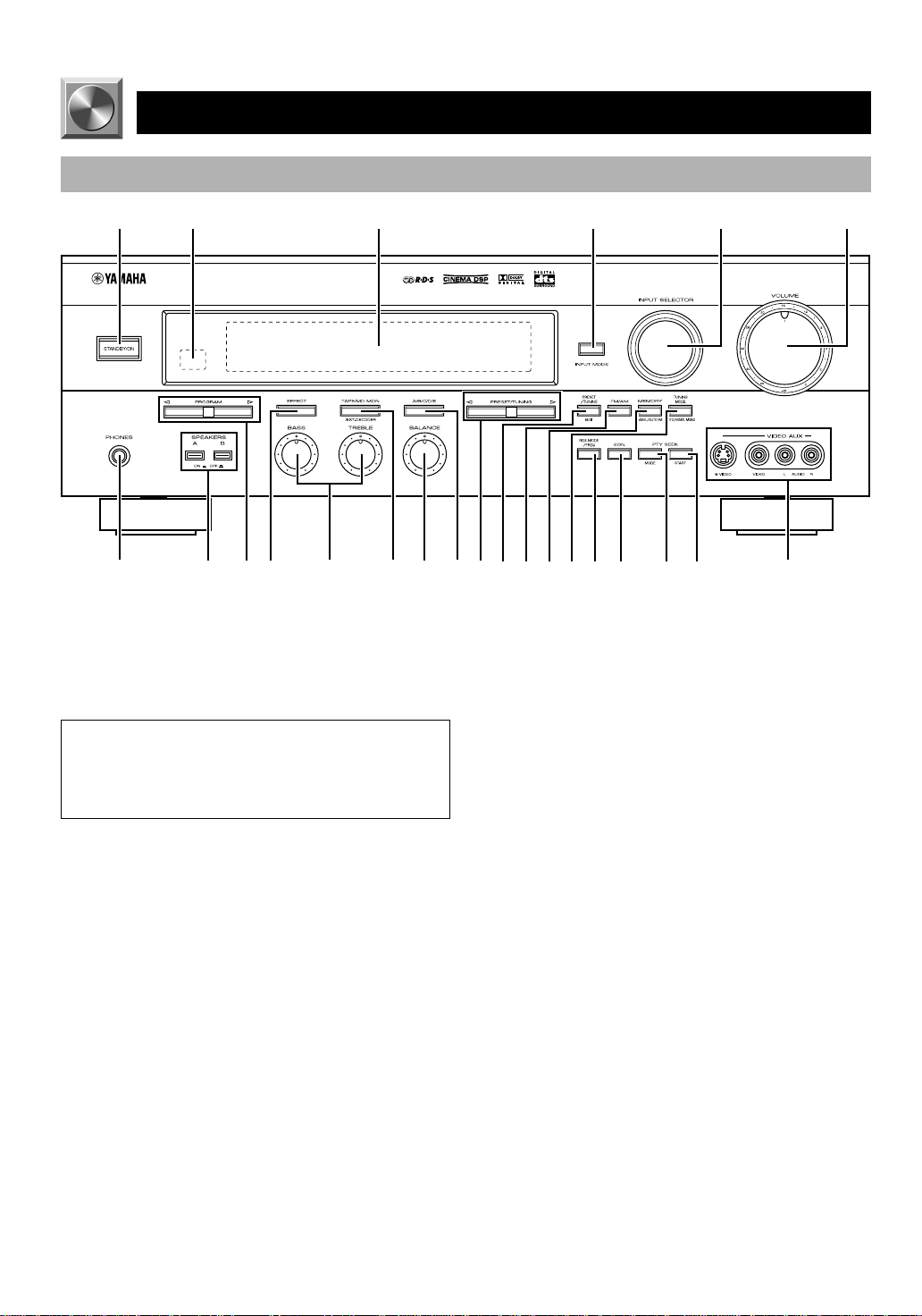
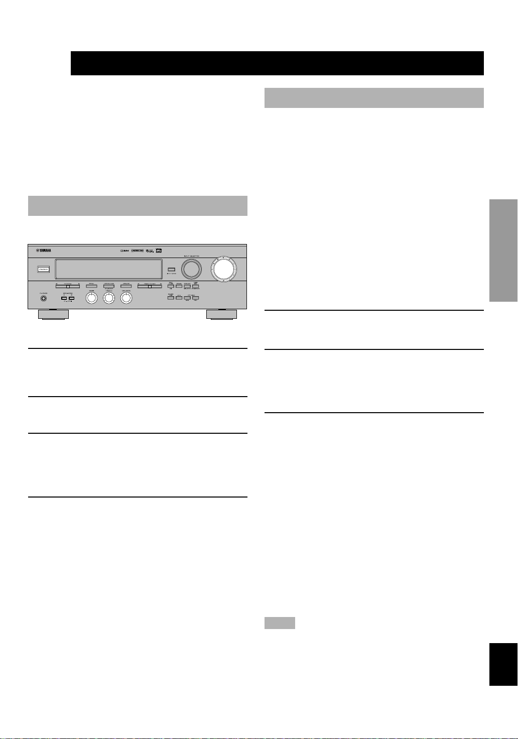
CONTROLS AND FUNCTIONS
Front Panel
12 3 4 65
+
–
+
–
LR
7890qwertyu i o p a s df
6
1 STANDBY/ON
Press this switch to turn on the power of this unit or to set
this unit in the standby mode. Before turning the power on,
set VOLUME to the “m” position.
Standby mode
In this mode, this unit consumes a very small quantity of
power to receive infrared-signals from the remote
control.
2 Remote control sensor
This receives signals from the remote control.
3 Display
This shows various information. (Refer to page 6 for
details.)
4 INPUT MODE
Press this button to select the input mode among AUTO,
DTS and ANALOG for the DVD/LD, TV/digital TV and
cable TV/satellite tuner sources.
5 INPUT SELECTOR
Turn this selector to select the input source (TUNER, CD,
PHONO, CBL/SAT, V-AUX, VCR, D-TV, DVD/LD) that
you want to listen to or watch. The arrow for the selected
input source indicator lights up on the display.
VOLUME
Turn this control to turn up or down the volume.
7 PHONES jack
Connect the headphones to the PHONES jack. You can
listen to the sound to be output from the main speakers
through the headphones.
When listening with headphones privately, set both
SPEAKERS A and B to the OFF position, press EFFECT to
turn off the effect speakers (center and rear) and set “BASS
OUT” on the SET MENU to the MAIN position (so that no
DSP program name appears on the display).
8 SPEAKERS
Set A or B (or both A and B) to the ON position for the main
speaker system (connected to this unit) that you want to use.
Set the button(s) to the OFF position for the main speaker
system that you don’t want to use.
9 PROGRAM selector
Press l or h to select a DSP program when the effect
speakers (center and rear) are turned on. The name of the
selected program appears on the display.
0 EFFECT
Press this button to turn on or off the effect speakers (center
and rear). If you turn them off, the signals of the center and
rear channels are directed to the right and left main speakers
when playing a source encoded with Dolby Digital and
DTS. In this case, the output levels of the right and left
speakers may not match.
4

CONTROLS AND FUNCTIONS
q Tone controls
These controls are only effective for the sound from the
main speakers.
a) BASS
Turn this control clockwise to increase or counterclockwise
to decrease the low-frequency response. The “0” position
produces a flat response.
b) TREBLE
Turn this control clockwise to increase or counterclockwise
to decrease the high-frequency response. The “0” position
produces a flat response.
w TAPE/MD MON / EXT. DECODER
Press this button to select a tape or an MD source. The
“TAPE/MD MONITOR” indicator lights up on the display.
When you press the button again, the “TAPE/MD
MONITOR” indicator goes off, “EXT. DECODER” appears
on the display and you can listen to a source connected to
the EXTERNAL DECODER INPUT terminals.
e BALANCE
This control is only effective for the sound from the main
speakers.
Turn the control to adjust the balance of the output volume
from the right and left main speakers to compensate for
sound imbalance caused by the speaker location or listening
room conditions.
r A/B/C/D/E
Press this button to select one of a group (A to E) of preset
stations.
t PRESET/TUNING
When “ z ” appears on the display
This button is used to select a preset station number (1 to 8).
Press h to select a higher and l to select a lower preset
station number.
When “ z ” goes off from the display
This button is used for tuning. Press h to tune in to higher
frequencies, and l to tune in to lower frequencies.
When this unit is in the PTY SEEK mode, press this button
to select a program type.
y PRESET/TUNING, EDIT
Press this button to turn on or off “ z ” on the display, and
switch the function between storing a broadcasting station
(preset tuning) and tuning. This button is also used to
exchange the assignment of two preset stations with each
other.
u FM/AM
Press this button to switch the reception band between FM
and AM.
i MEMORY (MAN’L/AUTO FM)
Press this button to store broadcasting stations. Hold down
this button for more than three seconds to begin automatic
preset tuning.
o TUNING MODE (AUTO/MAN’L MONO)
Press this button to switch the tuning mode between
automatic and manual. To use the automatic tuning method,
press this button so that the “AUTO” indicator lights up on
the display. To use the manual tuning method, press this
button so that the “AUTO” indicator goes off.
p RDS MODE/FREQ
When an RDS station is received, press this button to
change the display mode among the PS mode, PTY mode,
RT mode, CT mode (if the station offers those RDS data
services) and/or frequency display mode in turn.
a EON
Press this button to select the desired program type (NEWS,
INFO, AFFAIRS, SPORT) when you want to tune in to a
radio program of that type automatically.
s PTY SEEK MODE
Press this button to set the unit in the PTY SEEK mode.
d PTY SEEK START
Press this button to begin searching for a station after the
desired program type has been selected in the PTY SEEK
mode.
f VIDEO AUX terminals
Connect an auxiliary audio or video input source such as a
camcorder to these terminals. If the connected video unit
has an S video output terminal, connect it to the S VIDEO
terminal to obtain a high-resolution picture. Use INPUT
SELECTOR to select the source connected to these
terminals.
INTRODUCTION PREP ARA TION
ADV ANCED OPERA
TION APPENDIX
EnglishBASIC OPERATION
5

Display
8 MEMORY indicator
This flashes for about five seconds after pressing
MEMORY. During this period, the displayed station can be
stored in the memory.
9 RDS mode indicators
The name(s) of the RDS data offered by the currently
received RDS station light(s) up. Illumination of the red
indicator next to the RDS data name shows that the
corresponding RDS mode is now selected.
0 AUTO indicator
This lights up when the unit is in the automatic tuning
mode.
q PTY HOLD indicator
This lights up while searching for stations in the PTY SEEK
mode.
w EON indicator
This lights up when an RDS station that offers the EON data
service is being received.
e Program type name indicators
The name of the selected program type lights up when the
“EON” indicator lights up.
r STEREO indicator
This lights up when an FM stereo broadcast with sufficient
signal strength is being received.
t Signal-level indicator
This indicates the signal level of the station being received.
If multipath interference is detected, the indication
decreases.
y SLEEP indicator
This lights up while the built-in SLEEP timer is on.
6
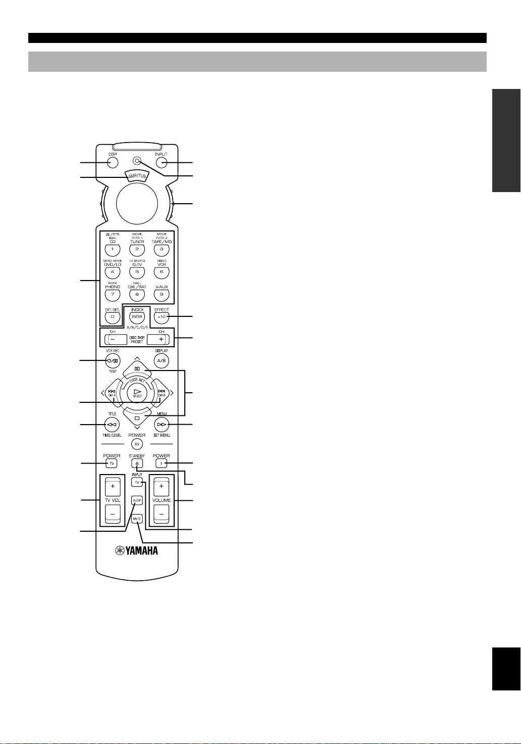
Remote Control
CONTROLS AND FUNCTIONS
This section describes the basic operation of this unit with
the remote control. First, set the selector dial to the AMP/
TUN position. Refer to “PRESET REMOTE CONTROL”
on page 45 for full details.
1
2
8
9
0
Select the
AMP/TUN
position.
3
EFFECT
Refer to
page 8.
q
4
w
5
6
e
1 DSP
Press this button to switch the function of the numeric
buttons to the DSP program selector. (Refer to page 8.)
2 Indicator window
This displays the name of components which can be
controlled.
3 Numeric buttons (Input selector buttons)
These buttons select the input source.
CD: To play a CD
TUNER: To listen to an FM (RDS) or AM broadcast
TAPE/MD: To play a tape or MD
DVD/LD: To play a DVD or LD
D-TV: To watch a TV
VCR: To play a video cassette
PHONO: To play an analog record
CBL/SAT: To watch cable TV or satellite broadcast
V-AUX: To use a camcorder
EXT. DEC.: To play another multi-channel source
Refer to page 8 for details.
4 TEST
Press this button to output the test tone for each speaker.
5 j (left), i (right)
These buttons adjust the settings of the SET MENU and
TIME/LEVEL mode.
6 TIME/LEVEL
Press this button to select the items in the TIME/LEVEL
mode.
INTRODUCTION PREP ARA TION
ADV ANCED OPERA
TV POWER
TV VOLUME
7
r
t
y
TV INPUT
u
7 SLEEP
Press this button to set the SLEEP timer.
8 INPUT
Press this button to switch the function of the numeric
buttons to the input selector. (Refer to page 8.)
9 Indicator
This flashes in red when pressing a button on the remote
control.
0 Selector dial
Turn this dial to select the position for the component to be
controlled. (The proper code must be set for your
component. Refer to “Setup codes” on page 51.) When the
position is selected, the remote control is set to that
component operation mode.
TION APPENDIX
EnglishBASIC OPERATION
7

CONTROLS AND FUNCTIONS
q A/B/C/D/E, PRESET +/–
These buttons are used to select a preset station.
A/B/C/D/E: To select one of a group (A to E) of preset
stations
PRESET +/–: To select a preset station number (1 to 8)
w d (next), u (back)
These buttons are used to advance or go back one selection
on the SET MENU and TIME/LEVEL mode.
e SET MENU
Press this button to select the items on the SET MENU.
r POWER
Press this button to turn this unit on.
t STANDBY
Press this button to set this unit in the standby mode.
y VOLUME (+/–)
These buttons are used to adjust the volume level.
u MUTE
Press this button to mute the sound. To cancel mute, press
this button again.
EFFECT
Press this button to turn on or off the effect speakers (center
and rear) in the following cases:
• When the selector dial is set to the DSP/TUN position.
• While the indicator is lit for about three seconds after
pressing DSP.
■ When selecting a DSP program
and turning on or off the effect
speakers (center and rear)
A
1 Press DSP regardless of the position of the
selector dial.
The indicator lights up for about three seconds.
2 You can select a DSP program with the
numeric buttons (1 to 8) and turn on or off the
effect speakers (center and rear) by pressing
EFFECT while the indicator is lit.
B
1 Set the selector dial to the DSP/TUN position.
2 You can select a DSP program directly with the
numeric buttons (1 to 8) and turn on or off the
effect speakers (center and rear) by pressing
EFFECT.
Description of the Numeric Buttons
The Numeric buttons function in various ways depending
on the position of the selector dial or the combination of
other instructions.
■ When selecting an input source
1 Press INPUT regardless of the position of the
selector dial.
The indicator lights up for about three seconds.
2 You can select an input source with the
numeric buttons while the indicator is lit.
■ When selecting a preset station
number
1 Set code number “0023” in the AMP/TUN (or
DSP/TUN) position.
Refer to page 51 for setting the code.
2 Set the selector dial to the AMP/TUN (or DSP/
TUN) position.
3 You can select a preset station number directly
with the numeric buttons (1 to 8).
Refer to page 29.
8
PREPARATION
SPEAKER SETUP
Speakers to Be Used
This unit is designed to provide the best sound-field quality
with a 5-speaker system, using main speakers, rear speakers
and a center speaker. If you use different brands of speakers
(with different tonal qualities) in your system, the tone of a
moving human voice and other types of sound may not shift
smoothly. We recommend that you use speakers from the
same manufacture or speakers with the same tonal quality.
The main speakers are used for the main source sound plus
the effect sounds. They will probably be the speakers from
your present stereo system. The rear speakers are used for
the effect and surround sounds, and the center speaker is for
the center sounds (dialog, vocals, etc.). If for some reason it
is not practical to use a center speaker, you can do without
it. Best results, however, are obtained with the full system.
The main speakers should be high-performance models and
have enough power-handling capacity to accept the
maximum output of your audio system. The other speakers
do not have to be equal to the main speakers. For precise
sound localization, however, it is ideal to use highperformance models that can reproduce sounds over the full
range for the center speaker and the rear speakers.
■ Use of a subwoofer expands your
sound field
It is also possible to further expand your system with the
addition of a subwoofer. The use of a subwoofer is effective
not only for reinforcing bass frequencies from any or all
channels, but also for reproducing the LFE (low frequency
effect) channel with high fidelity when playing back a
source encoded with Dolby Digital or DTS. The YAMAHA
Active Servo Processing Subwoofer System is ideal for
natural and lively bass reproduction.
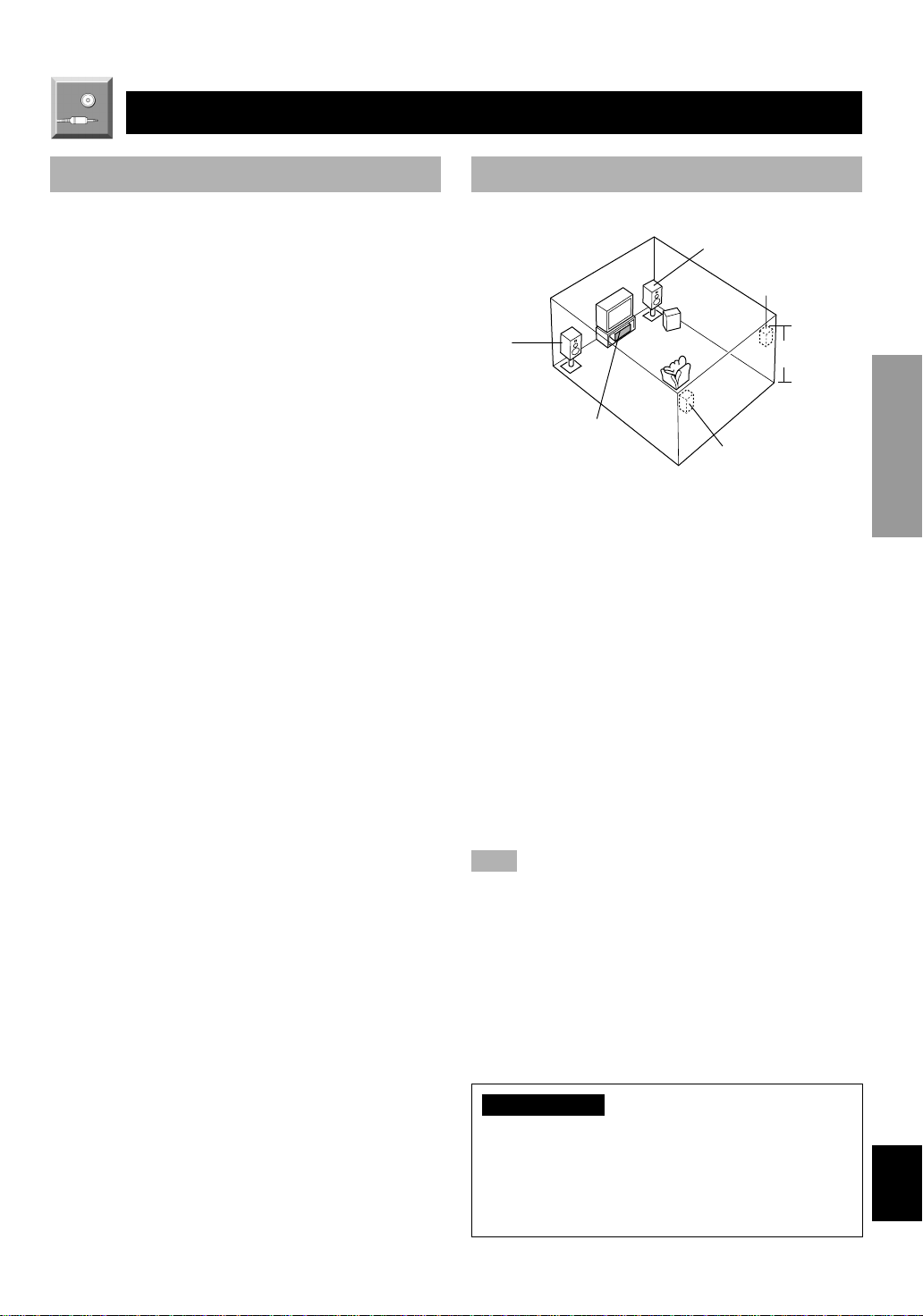
Speaker Placement
Refer to the following diagram when you place the
speakers.
Main
speaker (L)
Center speaker
■ Main speakers
Place the right and left main speakers an equal distance
from the ideal listening position. The distance of each
speaker from each side of the TV monitor should be the
same.
■ Rear speakers
Place these speakers behind your listening position, facing
slightly inwards, nearly 1.8 m (approx. 6 feet) above the
floor.
■ Center speaker
Align the front face of the center speaker with the front face
of your TV monitor. Place the speaker as close to the
monitor as possible, such as directly over or under the
monitor and centrally between the main speakers.
Note
• If the center speaker is not used, the center channel sound will be
heard from the right and left main speakers. In that case,
“CENTER SP” on the SET MENU is set to the NONE position.
(Refer to page 39 for details.)
Main speaker (R)
Rear speaker (R)
Subwoofer
1.8 m
Rear speaker (L)
INTRODUCTION
PREP ARA TION
ADV ANCED OPERA
TION APPENDIX
■ Subwoofer
The position of the subwoofer is not so critical, because low
bass sounds are not highly directional. But it is better to
place the subwoofer near the main speakers. Turn it slightly
toward the center of the room to reduce the wall reflections.
CAUTION
Some types of speakers interfere with a TV monitor. If
this problem occurs, move the speakers away from the
monitor. If you cannot avoid installing the center speaker
or subwoofer near the TV monitor, use magnetically
shielded speakers.
EnglishBASIC OPERATION
9
CONNECTIONS
V V
C C
L
R
L
R
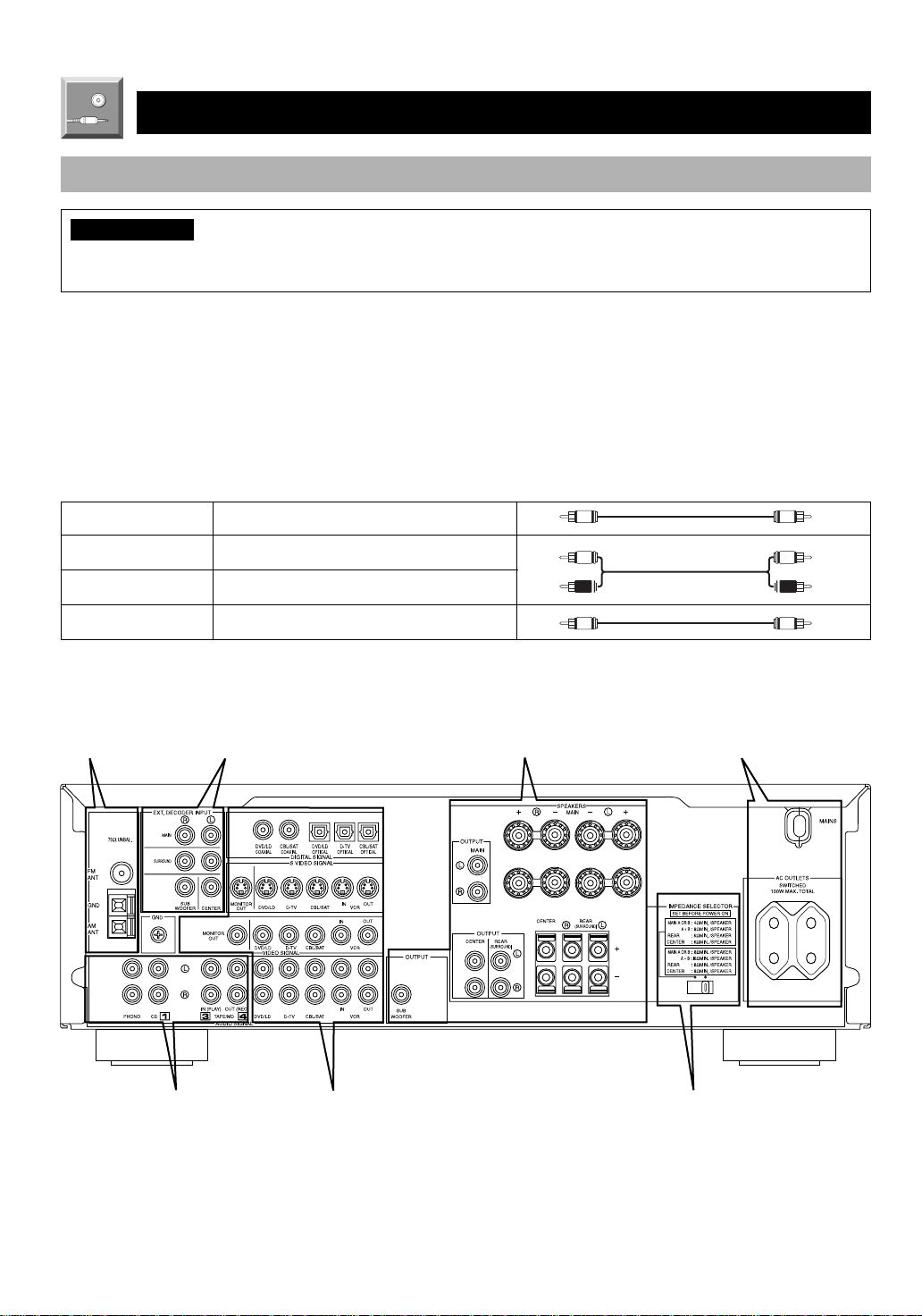
Before Connecting Components
CAUTION
Never connect this unit and other components to mains power until all connections between components have been
completed.
Be sure all connections are made correctly, that is to say L (left) to L, R (right) to R, “+” to “+” and “–” to “–”. Some
components require different connection methods and have different terminal names. Refer to the instructions for each
component to be connected to this unit.
When you connect other YAMAHA audio components (such as a tape deck, MD recorder and CD player or changer), connect
it to the terminals with the same number labels as !, #, $ etc. YAMAHA applies this labeling system to all its products.
Use RCA-type pin plug cables for connecting audio/video components with the exception described later.
The input and output terminals for pin plugs can be distinguished as follows:
Yellow video signals (composite)
White analog audio signals for the left channel
Red analog audio signals for the right channel
coaxial digital signals
After completing all connections, check them again to make sure they are correct.
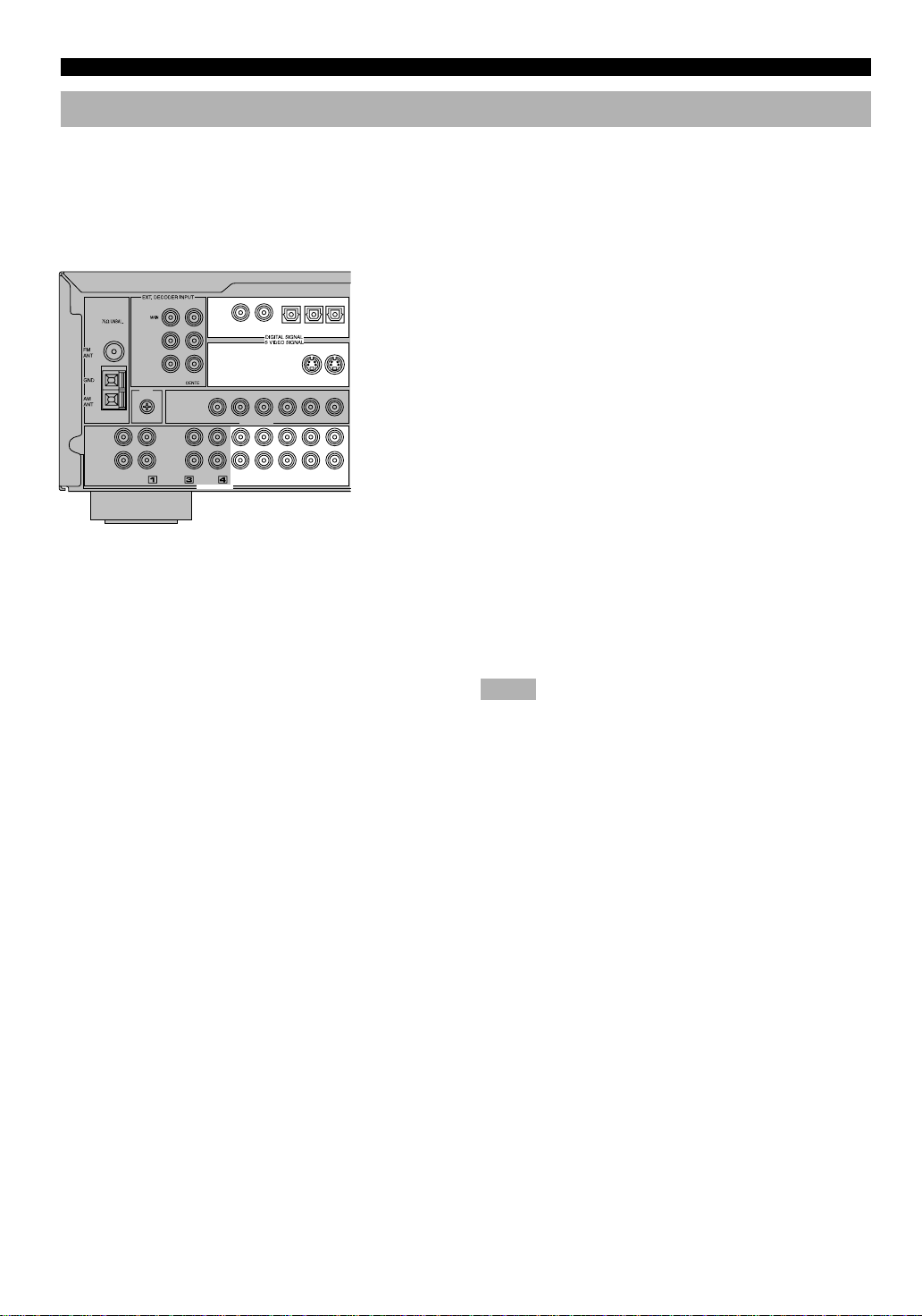
Connecting the Antenna
(pages 11 and 12)
Connecting an Audio
Component (page 13)
Connecting to an External
Decoder (page 15)
Connecting a Video
Component (pages 14 and 15)
Connecting the Speakers
(pages 16 and 17)
A
B
Connecting the Power
Supply Cords (page 18)
(Europe model)
IMPEDANCE SELECTOR
switch (page 18)
10
CONNECTIONS
Connecting the Antennas
Both AM and FM indoor antennas are included with this unit. In general, these antennas should provide sufficient signal
strength. However, a properly installed outdoor antenna provides clearer reception than an indoor one. If you experience poor
reception quality, an outdoor antenna may improve the quality.
Connect each antenna correctly to the designated terminals.
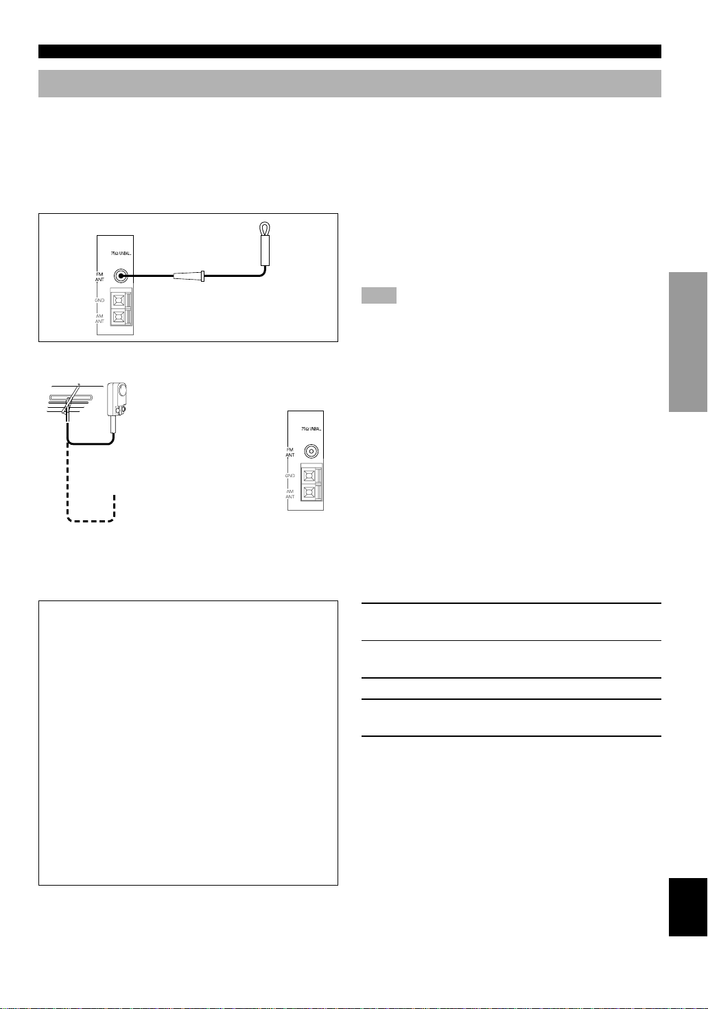
■ Indoor FM antenna (included)
Firmly insert the connector into the FM ANT terminal. The
indoor FM antenna is only a simple antenna. For reception
with better sound quality, installing the outdoor FM antenna
(commercially available) is recommended.
Note
• Do not connect an outdoor FM antenna and the indoor FM
antenna at the same time.
■ Outdoor FM antenna
You may be unable to obtain good FM radio reception
75-ohm/300-ohm antenna
adapter (included for U.K.
model)
depending on your local conditions (distance from the
broadcasting station, interposing buildings and
mountains, etc.). Consult your dealer or authorized service
center and be sure to install an antenna that suits your local
conditions.
Install the outdoor FM antenna (commercially available) in
a high place as far away from any roads as possible to avoid
being affected by automobile ignition noise.
INTRODUCTION
PREP ARA TION
■ Connecting a coaxial cable to the included 75-ohm/300-ohm antenna
adapter (U.K. model only)
1 Open the cover of the included 75-ohm/
300-ohm antenna adapter.
2 Cut the external sleeve of the 75-ohm coaxial
cable and prepare it for connection.
3 Cut the lead wire and remove it.
4 Insert the cable wire into the slot, and clamp it
with pliers.
5 Snap the cover into place.
ADV ANCED OPERA
TION APPENDIX
EnglishBASIC OPERATION
11
CONNECTIONS
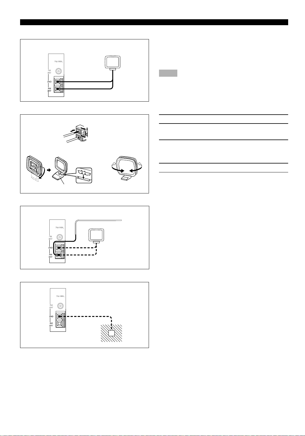
■ AM loop antenna (included)
AM loop antenna
■ Connecting the AM loop antenna
1
2
3
54
Antenna stand
The AM loop antenna can be removed from the stand and
attached to a wall, etc. However, note that the reception
sensitivity may deteriorate if the antenna is attached to a
metal or steel reinforced wall.
Notes
• The AM loop antenna should be placed away from this unit.
• The AM loop antenna should always be connected, even if an
outdoor AM antenna is connected to this unit.
1 Press the tab and unlock the terminal hole.
2 Insert the AM loop antenna lead wires into the
AM ANT and GND terminals.
3 Return the tab to its original position to lock
the lead wires. Lightly pull the lead wires to
confirm a good connection.
4 Attach the loop antenna to the antenna stand.
5 Orient the AM loop antenna so that the best
reception is obtained.
■ Outdoor AM antenna
Vinyl covered wire (5 m to 10 m)
■ Ground (GND terminal)
If you cannot obtain good reception with the AM loop
antenna, connect 5 m to 10 m of vinyl covered wire to the
AM ANT terminal and extend it outdoors from a window.
For maximum safety and minimum interference, connect
the antenna GND terminal to a good earth ground. A good
earth ground is a metal stake driven into moist earth.
12

Connecting an Audio Component
Turntable
OUTPUT
GND
CONNECTIONS
INTRODUCTION
L R
L R
OUTPUT LINE OUT LINE IN
CD player
L R L R
Tape deck or
MD recorder
Be sure to connect the right channel (R), left channel (L),
input (IN) and output (OUT) properly.
(Europe model)
Analog signal
L
R
Signal flow
■ PHONO terminals
These terminals are used to connect a turntable with an MM
or high-output MC cartridge. If you have a turntable with a
low-output MC cartridge, use an inline boosting transformer
or MC head amplifier when connecting to these terminals.
y
Connecting the ground (earth) wire of the turntable to the GND
terminal will normally minimize hum, but in some cases, better
results may be obtained with the ground wire disconnected.
PREP ARA TION
ADV ANCED OPERA
TION APPENDIX
13
EnglishBASIC OPERATION
CONNECTIONS
Connecting a Video Component
■ Audio signal terminals
Be sure to connect the right channel (R), left channel (L),
input (IN) and output (OUT) properly.
■ S Video signal terminals
Use a special S VIDEO cable (commercially available) for
the S VIDEO connection.
■ Digital audio signal terminals
If your DVD/LD player, TV/digital TV or cable TV/satellite
tuner, etc. has coaxial or optical digital signal output
terminals, they can be connected to this unit’s COAXIAL
and/or OPTICAL digital signal input terminals. To make a
connection between the optical digital signal terminals,
remove the cover from each terminal, and then connect
them by using a commercially available optical fiber cable
that conforms to EIA standards. Other cables might not
function correctly.
When making connections between the digital signal
terminals, you should connect the components to the samenamed analog audio signal terminals of this unit, because a
digital signal cannot be recorded by a tape deck, MD
recorder or VCR connected to this unit.
Notes
• Be sure to attach the covers when the OPTICAL terminals are not
being used in order to protect them from dust.
• If your LD player has a Dolby Digital RF signal output terminal,
be sure to use the RF demodulator (separately purchased).
• No sound will be heard when connecting your LD player’s Dolby
Digital RF signal output terminal directly to this unit’s COAXIAL
DVD/LD digital signal input terminal.
y
• The input signal from the DVD/LD or CBL/SAT input terminals
is selected in the following order of priority with the input mode
set to AUTO: COAXIAL terminal → OPTICAL terminal →
Analog terminal. Refer to page 23 for details.
• All digital signal input terminals are applicable to sampling
frequencies of 32 kHz, 44.1 kHz, 48 kHz and 96 kHz. (Refer to
page 24 about 96-kHz sampling 24-bit digital signals.)
14
■ VIDEO terminals (composite)
DVD/LD player
If your video components do not have “S” video terminals,
they can be connected to this unit’s VIDEO terminals. Be
sure to connect the input (IN) and output (OUT) properly.
Note
• If video signals are input from both the S VIDEO input and
composite input terminals, the signals will be directed to their
respective output terminals.
■ TV monitor with a 21-pin connector
Make a connection as shown above with a commercially available SCART-plug connector cable.
CONNECTIONS
INTRODUCTION
PREP ARA TION
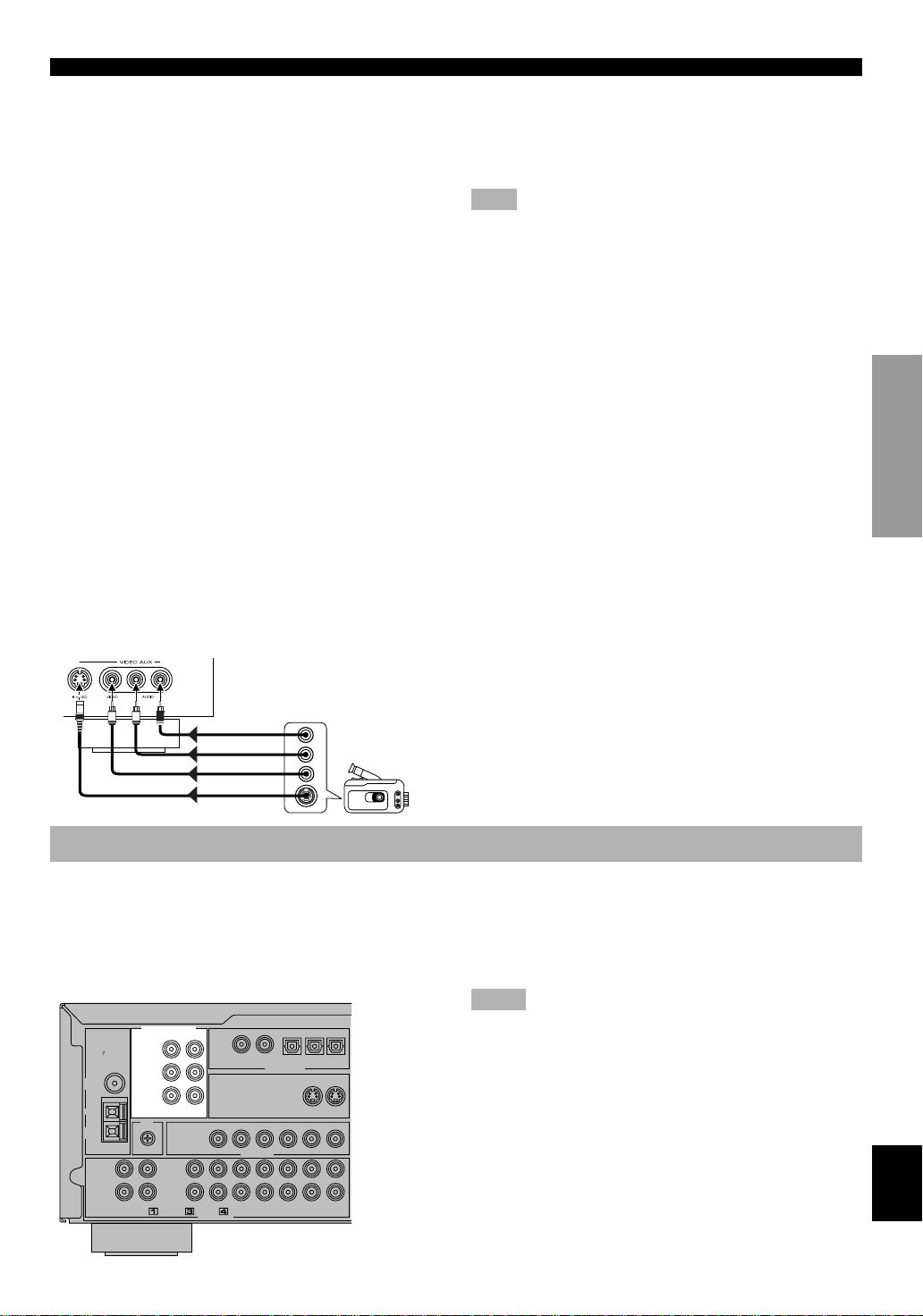
■ VIDEO AUX terminals (on the front panel)
These terminals are used to connect any video input source
S
V
L R
AUDIO OUT R
AUDIO OUT L
VIDEO OUT
S VIDEO OUT
such as a camcorder to this unit.
Connecting to an External Decoder
This unit has additional 6-channel audio signal input
terminals for connecting an external decoder to this unit.
Connect the 6-channel audio signal output terminals of the
decoder to the EXTERNAL DECODER INPUT terminals
of this unit.
Notes
• When a source connected to these terminals is selected, the digital
sound field processor cannot be used.
• The settings of “CENTER SP”, “REAR SP”, “MAIN SP” and
“BASS OUT” on the SET MENU have no effect on a source
connected to these terminals. The setting of “MAIN LVL” is
effective. (Refer to pages 39 and 40 for details.)
• Adjustment of the output level of the center speaker, rear speakers
and subwoofer is effective when a source connected to these
terminals is selected as the input source. (Refer to page 42 for
details.)
ADV ANCED OPERA
TION APPENDIX
EnglishBASIC OPERATION
15
CONNECTIONS
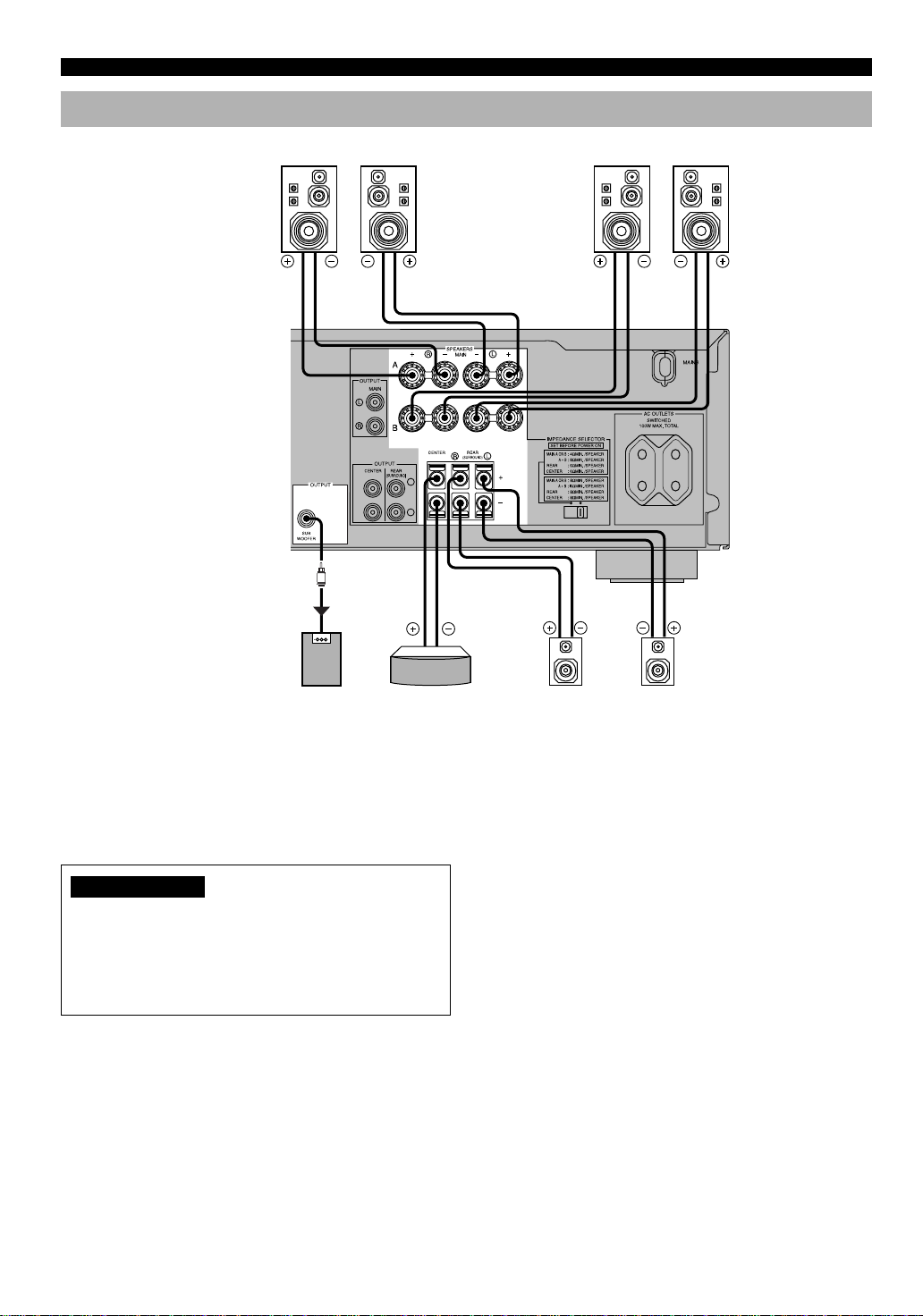
Connecting the Speakers
Right Left
Subwoofer connection
When using a subwoofer with builtin amplifier, including the
YAMAHA Active Servo Processing
Subwoofer System, connect the
input terminal of the subwoofer
system to the SUBWOOFER
OUTPUT terminal of this unit.
Low bass signals distributed from
the main, center and/or rear
channels are directed to this
terminal. (The cut-off frequency of
this terminals is 90 Hz.) The LFE
(low frequency effect) signals
generated when Dolby Digital or
DTS is decoded are also directed if
they are assigned to this terminal.
Main speakers A
Main speakers B
Right Left
(Europe model)
L
R
Subwoofer
system
Center speaker Rear speakers
Be sure to connect the right channel (R), left channel (L),
“+” (red) and “–” (black) properly. If the connections are
faulty, no sound will be heard from the speakers, and if the
polarity of the speaker connections is incorrect, the sound
will be unnatural and lack bass.
CAUTIONS
• Use speakers with the specified impedance shown on
the rear panel of this unit.
• Do not let the bare speaker wires touch each other and
do not let them touch any metal part of this unit. This
could damage the unit and/or speakers.
Right Left
■ MAIN SPEAKERS terminals
One or two speaker systems can be connected to these
terminals. If you use only one speaker system, connect it to
either of the SPEAKERS A or B terminals.
■ REAR SPEAKERS terminals
A rear speaker system can be connected to these terminals.
■ CENTER SPEAKER terminals
A center speaker can be connected to these terminals.
16
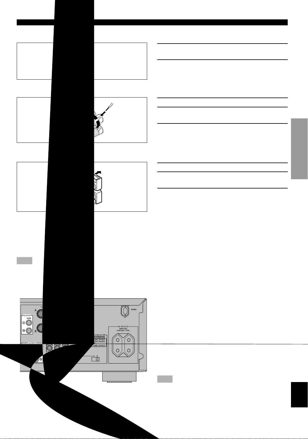
■ Speaker cables
1 Remove approx. 10 mm (3/8”) of insulation
from each of the speaker cables.
2 Twist the exposed wires of the cable together
to prevent short circuits.
■ Connecting to the MAIN SPEAKERS terminals
CONNECTIONS
INTRODUCTION
Red: positive (+)
Black: negative (–)
2
1
3
1 Unscrew the knob.
2 Insert one bare wire into the hole in the side of
each terminal.
3 Tighten the knob to secure the wire.
■ Connecting to the REAR and CENTER SPEAKERS terminals
Red: positive (+)
Black: negative (–)
1
3
2
1 Open the tab.
2 Insert one bare wire into the hole of each
terminal.
3 Return the tab to secure the wire.
■ Connecting to an external amplifier
The speaker connections described on page 16 are fine for most applications. If you wish to drive your existing amplifier, the
following terminals are available for connecting an external amplifier(s) to this unit.
Note
• Output signals from these terminals are affected by the use of VOLUME, BASS, TREBLE and BALANCE.
PREP ARA TION
ADV ANCED OPERA
1 MAIN OUTPUT terminals
These terminals are for the main channel line output.
Connect the input terminals of the external amplifier to
these terminals.
2 CENTER OUTPUT terminals
These terminals are for the center channel line output.
Connect the input terminals of the external amplifier to
these terminals.
3 REAR (SURROUND) OUTPUT terminals
These terminals are for the rear channel line output.
Connect the input terminals of the external amplifier to
these terminals.
Note
• If an external amplifier is connected to the MAIN, CENTER or
REAR OUTPUT terminals, disconnect the corresponding
speakers (main, center or rear) from the SPEAKERS terminals.
TION APPENDIX
EnglishBASIC OPERATION
17
CONNECTIONS
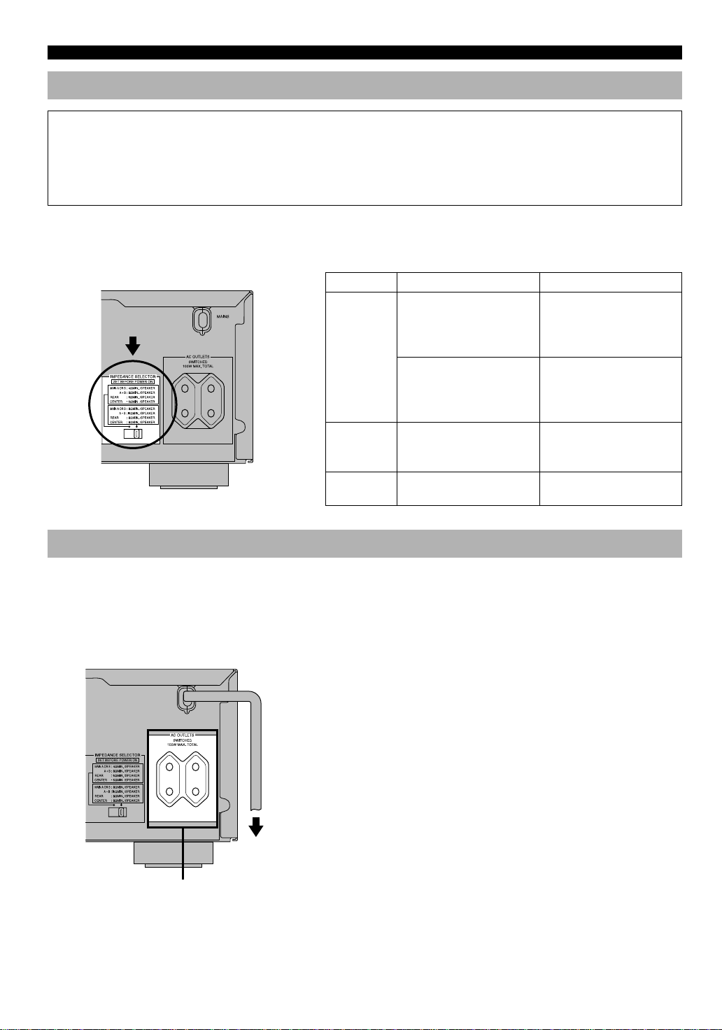
IMPEDANCE SELECTOR Switch
WARNING
Do not change the IMPEDANCE SELECTOR switch setting while the power of this unit is on, otherwise the unit may be
damaged.
If this unit fails to turn on when STANDBY/ON (or POWER) is pressed, the IMPEDANCE SELECTOR switch may not
be fully slide to either position. If so, slide the switch to either position fully when this unit is in the standby mode.
Select the right or left position according to the impedance of speakers in your system. Be sure to move this switch only
when this unit is in the standby mode.
(Europe model)
IMPEDANCE
SELECTOR
Connecting the Power Supply Cords
■ AC OUTLETS (SWITCHED)
(Europe model)
If you use left position right position
If you use one pair of main
speakers, the impedance of
each speaker must be 4 Ω or
Main
speakers
Rear speakers The impedance of each
Center
speaker
higher.
If you use two pairs of main
speakers, the impedance of
each speaker must be 8 Ω or
higher.
speaker must be 6 Ω or
higher.
The impedance must be 6 Ω
or higher.
If you use one pair of main
speakers, the impedance of
each speaker must be 8 Ω or
higher.
If you use two pairs of main
speakers, the impedance of
each speaker must be 16 Ω or
higher.
The impedance of each
speaker must be 8 Ω or
higher.
The impedance must be 8 Ω
or higher.
After completing all connections, connect the AC power
cord to an AC power outlet. Disconnect the AC power cord
if you will not use this unit for a long period of time.
Europe model ....................................................2 OUTLETS
U.K. model.......................................................... 1 OUTLET
Use these outlets to connect the power cords from your
components to this unit. The power to the AC OUTLET(S)
is controlled by this unit’s STANDBY/ON (or POWER and
STANDBY). These outlets will supply power to any
connected component whenever this unit is turned on. The
maximum power (total power consumption of components)
that can be connected to the AC OUTLET(S) is 100 W.
18
To AC outlet
SWITCHED
ADJUSTING THE SPEAKER BALANCE
This procedure lets you adjust the sound output level
balance between the main, center and rear speakers by using
the built-in test tone generator. When this adjustment is
performed, the sound output level heard at the listening
position will be the same from each speaker. This is
important for the best performance of the digital sound field
processor, the Dolby Pro Logic decoder, Dolby Digital
decoder and DTS decoder.
Before You Start Adjusting
1 Set VOLUME to the “m”
position.
Using the Test Tone
The adjustment of each speaker sound output level should
be performed at your listening position with the remote
control. After completing the adjustments, use VOLUME
(+/–) at your listening position to check if the adjustments
are satisfactory.
1 Set the selector dial to the
AMP/TUN (or DSP/TUN)
position.
2 Press TEST .
“TEST LEFT” appears on the display.
INTRODUCTION
PREP ARA TION
2 Turn the power on.
3 Press SPEAKERS A or B
to select the main
speakers to be used.
If you use two main speaker
systems, press both A and B.
4 Set BASS, TREBLE and BALANCE to the “0”
position.
3 Turn up the volume.
You will hear a test tone (like pink noise) from each
speaker for about two seconds in the following order:
left main speaker, center speaker, right main speaker,
right rear speaker and left rear speaker. The display
changes as shown below.
Notes
• If the test tone cannot be heard, turn down the volume, set the unit
in the standby mode and check the speaker connections.
• If the test tone cannot be heard from the center speaker, check the
setting of “CENTER SP” on the SET MENU.
ADV ANCED OPERA
TION APPENDIX
EnglishBASIC OPERATION
19
 Loading...