

Yamaha RXV-595-ARDS Service manual

AV RECEIVER
RX-V595a/HTR-5150/
RX-V595aRDS
SERVICE MANUAL
IMPORTANT NOTICE
This manual has been provided for the use of authorized YAMAHA Retailers and their service personnel.
It has been assumed that basic service procedures inherent to the industry, and more specifically YAMAHA
Products, are already known and understood by the users, and have therefore not been restated.
WARNING: Failure to follow appropriate service and safety procedures when servicing this product
IMPORTANT:The presentation or sale of this manual to any individual of firm does not constitute
The data provided is believed to be accurate and applicable to the unit(s) indicated on the cover. The research,
engineering, and service departments of YAMAHA are continually striving to improve YAMAHA products.
Modifications are, therefore, inevitable and specifications are subject to change without notice or obligation
to retrofit. Should any discrepancy appear to exist, please contact the distributor's Service Division.
WARNING: Static discharges can destroy expensive components. Discharge any static electricity
IMPORTANT:Turn the unit OFF during disassembly and part replacement. Recheck all work before
may result in personal injury, destruction of expensive components, and failure of the
product to perform as specified. For these reasons, we advise all YAMAHA product
owners that any service required should be performed by an authorized YAMAHA
Retailer or the appointed service representative.
authorization, certification or recognition of any applicable technical capabilities,
or establish a principle-agent relationship of any form.
your body may have accumulated by grounding yourself to the ground buss in the unit
(heavy gauge black wires connect to this buss).
you apply power to the unit.
■CONTENTS
TO SERVICE PERSONNEL ........................................... 1
REMOTE CONTROL PANELS....................................... 1
FRONT PANELS............................................................. 2
REAR PANELS ........................................................... 3~4
SPECIFICATIONS.......................................................5~6
INTERNAL VIEW ............................................................ 7
DISASSEMBLY PROCEDURES .................................... 7
SELF DIAGNOSIS FUNCTION ................................ 8~19
FACTORY PRESET ...................................................... 20
100679
AMP ADJUSTMENT ..................................................... 21
TUNER ADJUSTMENT........................................... 22~25
IC DATA .................................................................. 26~36
DISPLAY DATA ........................................................... 37
BLOCK DIAGRAM.................................................. 38~41
PRINTED CIRCUIT BOARD ...................................42~59
SCHEMATIC DIAGRAM ......................................... 60~67
PARTS LIST ............................................................68~85
REMOTE CONTROL TRANSMITTER ......................... 86
RX-V595a/HTR-5150/RX-V595aRDS
■ TO SERVICE PERSONNEL
1. Critical Components information.
Components having special characteristics are marked and must be
replaced with parts having specifications equal to those originally
installed.
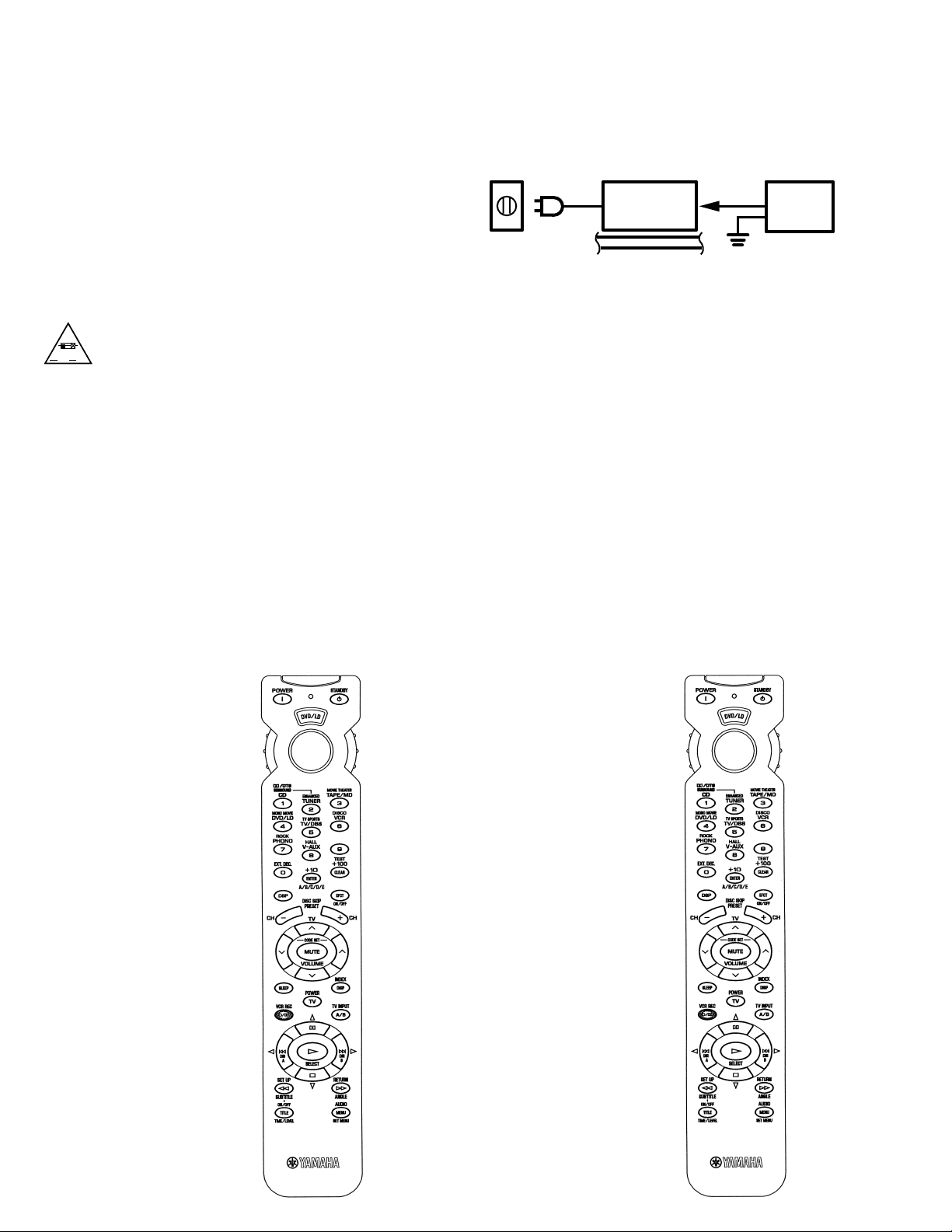
2. Leakage Current Measurement (For 120V Model only).
When service has been completed, it is imperative that you verify that
all exposed conductive surfaces are properly insulated from supply
circuits.
Meter impedance should be equivalent to 1500 ohm shunted by 0.15µF.
•
Leakage current must not exceed 0.5mA.
•
Be sure to test for leakage with the AC plug in both polarities.
•
WALL
OUTLET
EQUIPMENT
UNDER TEST
INSULATING
TABLE
AC LEAKAGE
TESTER OR
EQUIVALENT
"CAUTION"
"F804: FOR CONTINUED PROTECTION AGAINST RISK OF FIRE,REPLACE ONLY WITH SAME TYPE 8.0A, 250V FUSE."
CAUTION
A V
F804: REPLACE WITH SAME TYPE 8.0A, 250V FUSE.
ATTENTION
F804: UTILISER UN FUSIBLE DE RECHANGE DE MEME TYPE DE 8.0A, 250V FUSE.
ˆ
WARNING: CHEMICAL CONTENT NOTICE!
The solder used in the production of this product contains LEAD. In addition, other electrical/electronic and/or plastic (where
applicable) components may also contain traces of chemicals found by the California Health and Welfare Agency (and possibly
other entities) to cause cancer and/or birth defects or other reproductive harm.
DO NOT PLACE SOLDER, ELECTRICAL/ELECTRONIC OR PLASTIC COMPONENTS IN YOUR MOUTH FOR ANY REASON
WHATSOEVER!
Avoid prolonged, unprotected contact between solder and your skin! When soldering, do not inhale solder fumes or expose eyes
to solder/flux vapor!
If you come in contact with solder or components located inside the enclosure of this product, wash your hands before handling
food.
■ REMOTE CONTROL PANELS
▼ U,C,R,T and L models ▼ A,B and G models
RAV174
V383640 US
RAV175
V38650 EU
1
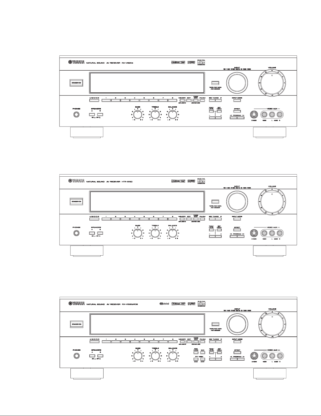
■ FRONT PANELS
▼ RX-V595a (U, C, R, T, A and L models)
RX-V595a/HTR-5150/RX-V595aRDS
▼ HTR-5150 (U, C, T and A models)
▼ RX-V595aRDS (B and G models)
2
RX-V595a/HTR-5150/RX-V595aRDS
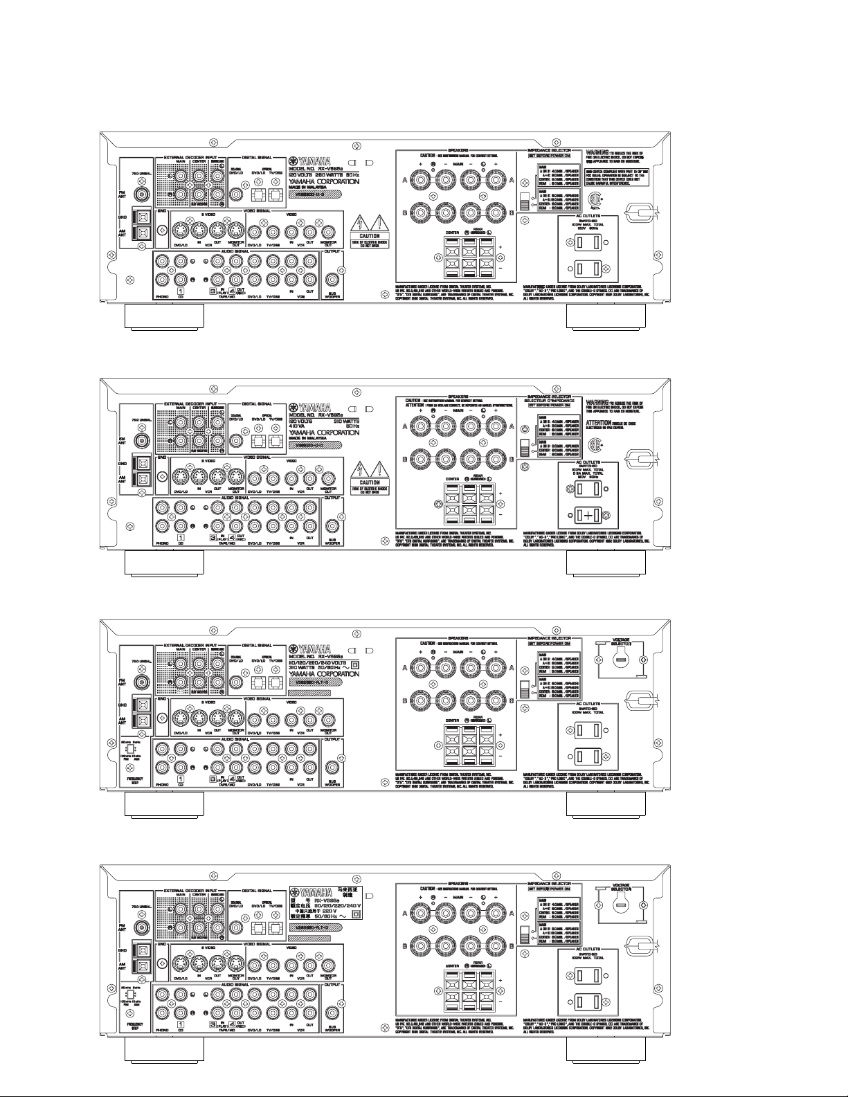
■ REAR PANELS
▼ RX-V595a/HTR-5150 U model
▼ RX-V595a/HTR-5150 C model
▼ RX-V595a R model
▼ RX-V595a/HTR-5150 T model
3
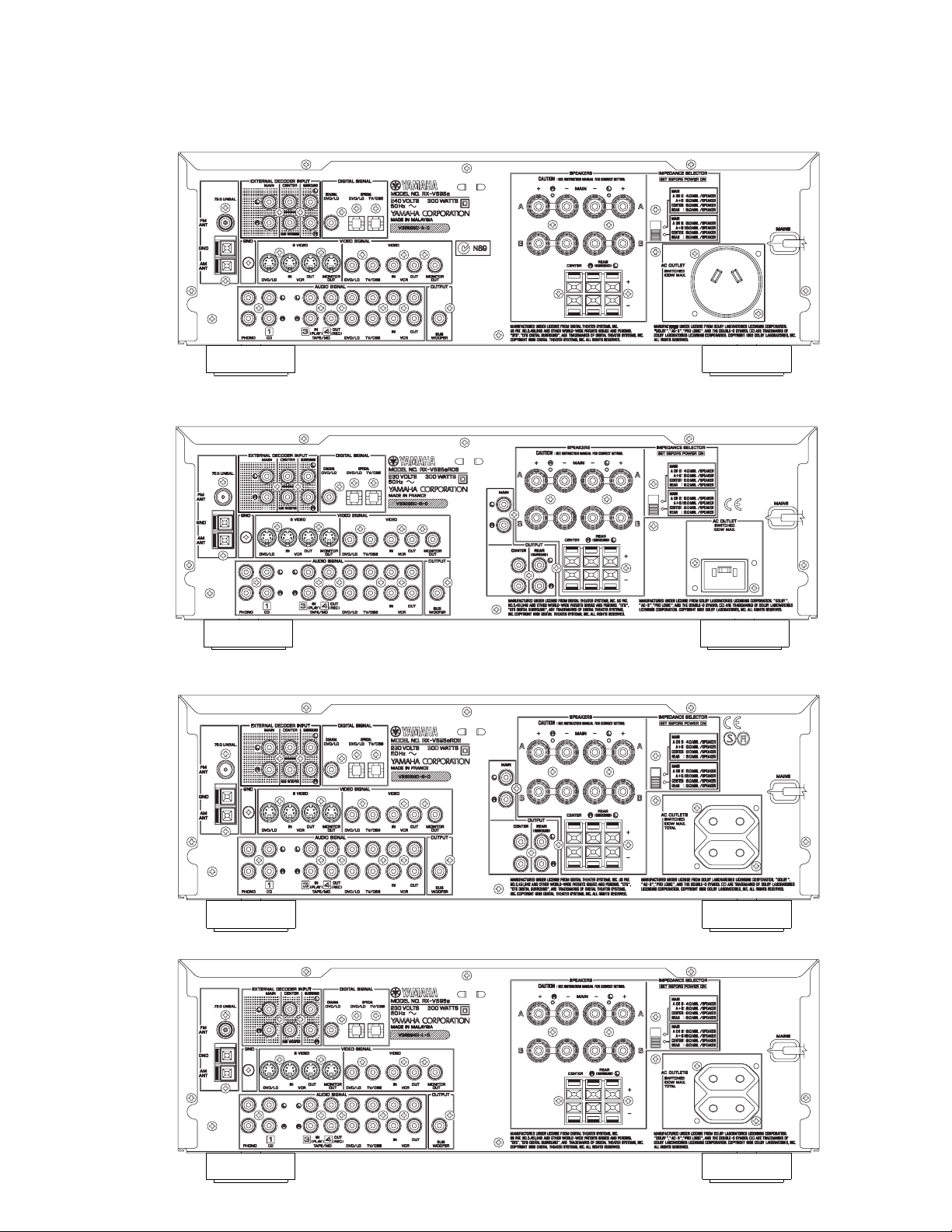
▼ RX-V595a/HTR-5150 A model
▼ RX-V595aRDS B model
RX-V595a/HTR-5150/RX-V595aRDS
▼ RX-V595aRDS G model
▼ RX-V595a L model
4

RX-V595a/HTR-5150/RX-V595aRDS
■ SPECIFICATIONS
■AUDIO SECTION
Minimum RMS Output Power Per Channel
(Power Amp. Section)
U, C models
MAIN L/R, REAR L/R
20Hz to 20kHz, 0.04% THD, 8Ω 70W+70W
1kHz, 0.07% THD, 8Ω 85W+85W
CENTER
20Hz to 20kHz, 0.04% THD, 8Ω 70W
1kHz, 0.07% THD, 8Ω 85W
R,T,A,B,G,L models
MAIN L/R, REAR L/R
20Hz to 20kHz, 0.04% THD, 8Ω 65W+65W
1kHz, 0.07% THD, 8Ω 80W+80W
CENTER
20Hz to 20kHz, 0.04% THD, 8Ω 65W
1kHz, 0.07% THD, 8Ω 80W
Maximum Power (EIAJ)
R, T models only
MAIN L/R, REAR L/R
1kHz, 10% THD, 8Ω 105W+105W
CENTER, 1kHz, 10% THD, 8Ω 105W
Dynamic Power Per Channel (IHF)
MAIN L/R
U, C models
8/6/4/2Ω
100W+100W/120W+120W/145W+145W/170W+170W
R,T,A,B,G,L models
8/6/4/2Ω
90W+90W/110W+110W/135W+135W/160W+160W
DIN Standard Output Power Per Channel
G model only
MAIN L/R, 1kHz, 0.7% THD, 4Ω 110W+110W
Dynamic Headroom(8Ω)
U, C models only 1.55dB
IEC Power
G model only
MAIN L/R, 1kHz, 0.04% THD, 8Ω 75W+75W
Power Band Width
MAIN L/R, 0.1% THD, 35W, 8Ω 10Hz to 50kHz
Damping Factor (SPEAKER A)
MAIN L/R, 20Hz to 20kHz, 8Ω 60
Input Sensitivity/Input Impedance
PHONO (MM) 2.5mV/47kΩ
CD etc. 150mV/47kΩ
MAIN L/R (EXTERNAL DECODER) 150mV/47kΩ
CENTER 150mV/40kΩ
SURROUND L/R 150mV/40kΩ
SUB WOOFER 150mV/40kΩ
Maximum Input Signal Level (1kHz)
PHONO (MM), 0.1% THD 100mV
CD etc. (EFFECT ON), 0.5% THD 2.2V
Output Level/Output Impedance
REC OUT 150mV/1.2kΩ
SUB WOOFER (MAIN SP : SMALL) 2.1V/1.2KΩ
B,G models only
PRE OUT 4V/1.2KΩ
Headphone Jack Rated Output/Impedance
CD etc., Input=1kHz, 150mV, RL=8Ω 0.5V/390Ω
Frequency Response(20Hz to 20kHz)
CD etc., MAIN 0±0.5dB
RIAA Equalization Deviation
PHONO (MM) 0±0.5dB
Total Harmonic Distortion(20Hz to 20kHz)
PHONO (MM) to REC OUT (1V) 0.02%
CD etc.(EFFECT OFF) to MAIN SP OUT(35W/8Ω)
0.025%
Signal-to-Noise Ratio(IHF-A Network)
PHONO (MM), Input 5mV shorted, REC OUT
U, C, R, T models 86dB
A, B, G, L models 81dB
CD etc,(EFFECT OFF), Input 150mV shorted, SP OUT
96dB
Residual Noise(IHF-A Network)
MAIN L/R, SP OUT 150µV
Channel Separation(Vol. –30dB, EFFECT OFF)
PHONO, Input shorted, 1kHz/10kHz 60dB/55dB
CD etc, Input 5.1kΩ terminated, 1kHz/10kHz
60dB/45dB
Tone Control Characteristics
BASS : Boost/Cut ±10dB(50Hz)
: Turnover Frequency 350Hz
TREBLE : Boost/Cut ±10dB(20kHz)
: Turnover Frequency 3.5kHz
Filter Characteristics
MAIN, REAR SP SMALL : H.P.F. fc=90Hz, 12dB/oct.
SUB WOOFER : L.P.F. fc=90Hz, 18dB/oct.
■FM SECTION
Tuning Range
U, C models 87.5 to 107.9MHz
R, T models (Frequency Step: 100kHz)
87.5 to 108.0MHz
(Frequency Step: 50kHz)
87.50 to 108.00MHz
A, B, G, L models 87.50 to 108.00MHz
50dB Quieting Sensitivity (IHF)
U, C, R, T models only
Mono, 1kHz, 100% mod 1.6µV(15.3dBf)
Stereo, 1kHz, 100% mod 23µV(38.5dBf)
Usable Sensitivity (DIN)
A, B, G, L models only
DIN, Mono(S/N 26dB) 0.9µV
DIN, Stereo(S/N 46dB) 28µV
Alternate Channel Selectivity
U, C, R, T models (±400kHz) 75dB
A, B, G, L models (±300kHz)
Selectivity(two signals, 40kHz Dev.) 55dB
Signal-to-Noise Ratio
U, C, R, T models (IHF)
Mono/Stereo 81dB/75dB
A, B, G, L models (DIN-Weighted, 40kHz Dev.)
Mono/Stereo 75dB/69dB
Harmonic Distortion (1kHz)
Mono/Stereo 0.1%/0.2%
Stereo Separation (1kHz) 48dB
Frequency Response (20Hz to 15kHz) 0±1dB
Output Level (1kHz)
U, C, R, T models (100% mod.) 550mV
A, B, G, L models (40kHz Dev.) 550mV
Antenna Input 75Ω unbalanced
5
RX-V595a/HTR-5150/RX-V595aRDS
■AM SECTION
Tuning Range
U, C models 530 to 1710kHz
R, T models (Frequency Step : 10kHz) 530 to 1710kHz
(Frequency Step : 9kHz) 531 to 1611kHz
A, B, G, L models 531 to 1611kHz
Usable Sensitivity 300µV/m
Signal-to-Noise Ratio 52dB
Output Level (1kHz, 30% mod.) 150mV
Antenna Loop antenna
■VIDEO SECTION
Video Signal Type
U, C models NTSC
R model NTSC/PAL
T, A, B, G, L models PAL
Video Signal Level 1Vp-p/75Ω
S-Video Signal Level
Y:1Vp-p/75Ω,C:0.286Vp-p/75Ω
Maximum Input Level 1.5Vp-p
Signal-to-Noise Ratio 50dB
Monitor Output Frequency Response(–3dB) 5Hz~10MHz
■GENERAL
Power Supply
U, C, models AC120V, 60Hz
R model AC110/120/220/240V, 50/60Hz
T model AC220V, 50Hz
A model AC240V, 50Hz
B, G, L models AC230V, 50Hz
Power Consumption
U model 280W
C model 310W/410VA
R, T models 310W
A, B, G, L models 300W
Maximum Power Consumption
R model only
5CH Simultaneous output, 10% THD 650W
AC Outlet
U, C, R, T, G, L models, Switched x 2 100W max(Total)
A, B models, Switched x 1 100W max
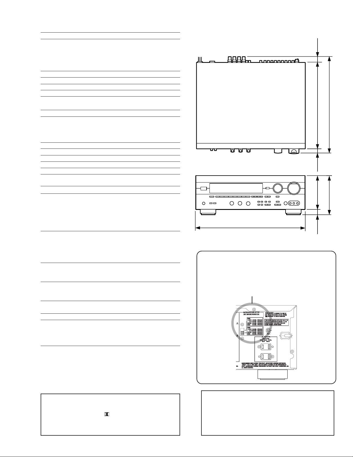
Dimensions(W x H x D) 435 x 151 x 391mm
(17-1/8" x 5-15/16" x 15-3/8")
Weight 12.5kg(27Ibs. 9 oz)
Accessories AM loop antenna x 1
Indoor FM antenna x 1
Remote Control Transmitter x 1
Battery (siza "AA", "R06") x 2
●DIMENSIONS
21.5
349.5(13-3/4")
130(5-3/32")
435(17-1/8")
Units: mm (inch)
WARNING
Do not change the IMPEDANCE SELECTOR switch
setting while the power to this unit is on, otherwise
this unit may be damaged.
IMPEDANCE SELECTOR
(7/8")
391(15-3/8")
20
(13/16")
151(5-15/16")
21
(27/32")
* Specifications subject to change without notice.
U ......... U. S. A. model A ......... Australian model
C ......... Canadian model B .........British model
R ......... General model G ......... European model
T.......... China model L .......... Singapore model
Manufactured under license from Dolby Laboratories
Licensing Corporation."DOLBY" , "AC-3", "Pro Logic", and
the double-D symbol
are trademarks of Dolby
Laboratories Licensing Corporation. Copyright 1992 Dolby
Laboratories, inc. All rights reserved.
Manufactured under license from Digital Theater
Systems, Inc. US Pat. No. 5,451,942 and other wirldwide patents issued and pending. "DTS", "DTS
Digital Surround", are trademarks of Digital Theater
Systems, Inc. Copyright 1996 Digital Theater
Systems, inc. All rights reserved.
6
RX-V595a/HTR-5150/RX-V595aRDS
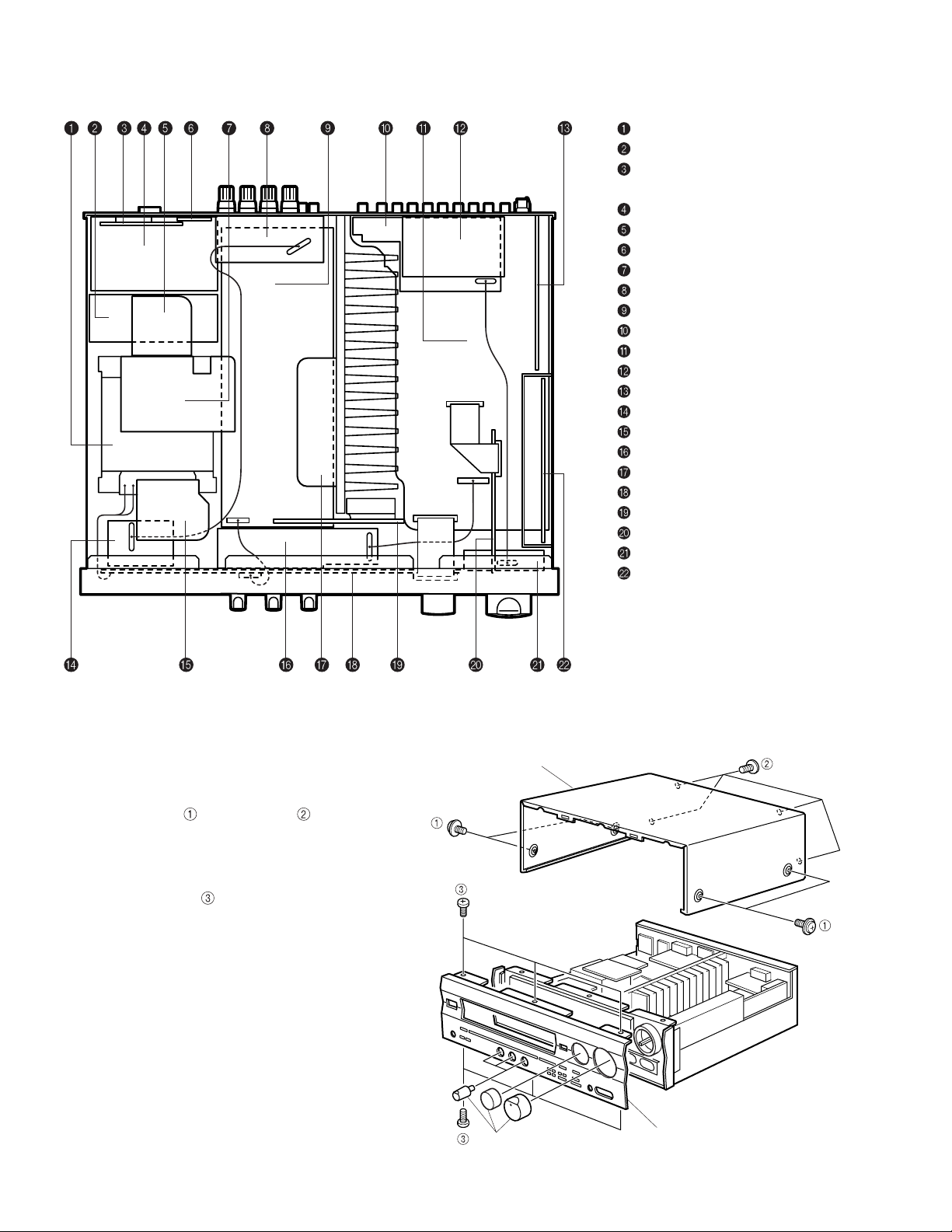
■ INTERNAL VIEW
POWER TRANSFORMER
P.C.B. MAIN (3)
P.C.B. OPERATION (7)
(R, T models only)
P.C.B. OPERATION (3)
P.C.B. MAIN (4)
P.C.B. MAIN (8)
P.C.B. OPERATION (6)
P.C.B. MAIN (2)
P.C.B. MAIN (1)
P.C.B. VIDEO
P.C.B. INPUT (1)
P.C.B. INPUT (3)
P.C.B. TUNER
P.C.B. MAIN (5)
P.C.B. OPERATION (5)
P.C.B. OPERATION (4)
P.C.B. MAIN (7)
P.C.B. OPERATION (1)
P.C.B. MAIN (6)
P.C.B. INPUT (4)
P.C.B. OPERATION (2)
P.C.B. DSP
■ DISASSEMBLY PROCEDURES
(Remove parts in disassembly order as numbered.)
1. Removal of Top Cover
Remove 4 screws (
2. Removal of Front Panel
a. Remove 5 knobs.
b. Remove 6 screws ( ) in Fig. 1.
7
) and 4 screws ( ) in Fig. 1.
Knob
Top Cover
Front Panel
Fig.1

RX-V595a/HTR-5150/RX-V595aRDS
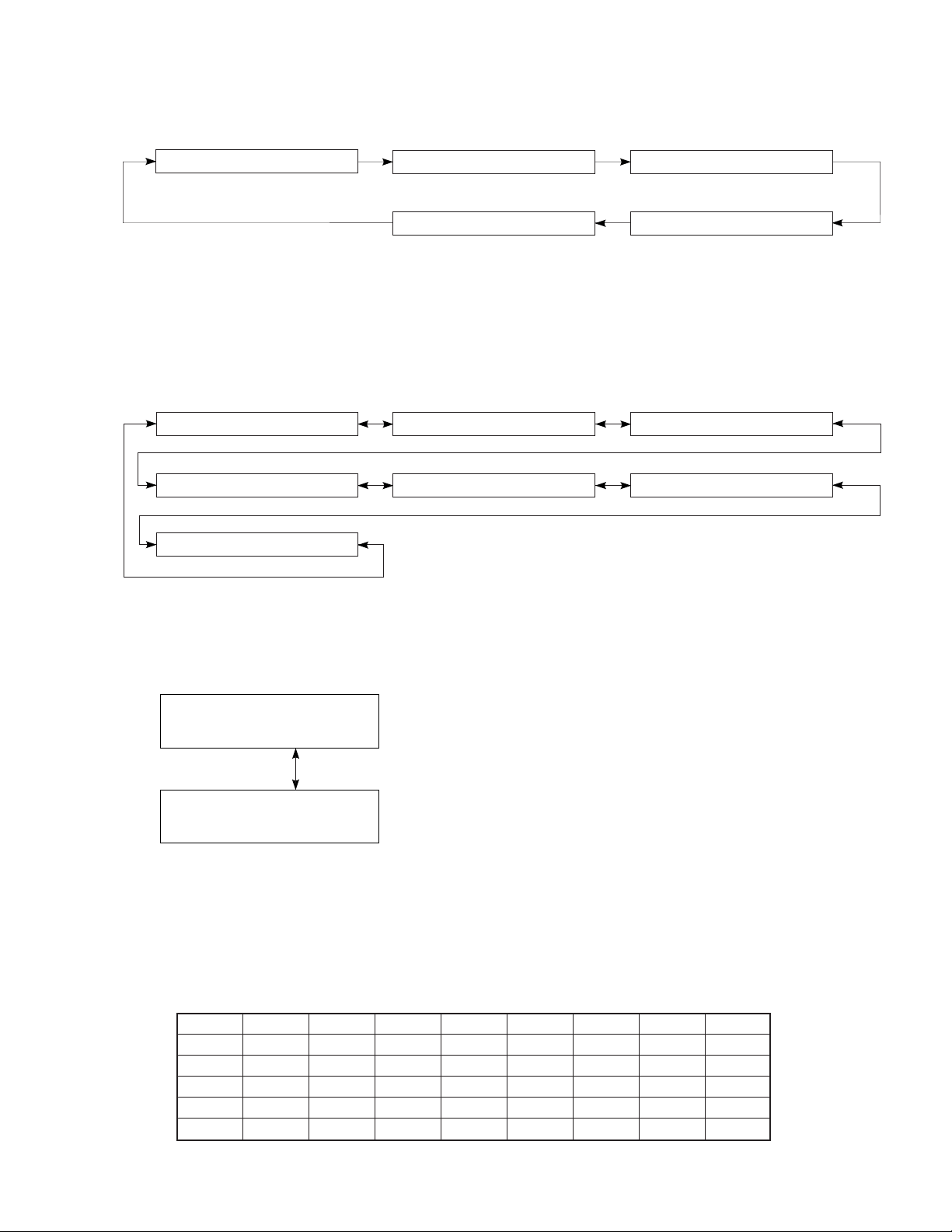
■ SELF DIAGNOSIS FUNCTION
1. PURPOSE AND OPERATION
The RX-V595a/HTR-5150/RX-V595aRDS has a Self Diagnosis Function to locate a faulty part, if any, by inspecting and taking
measurements.
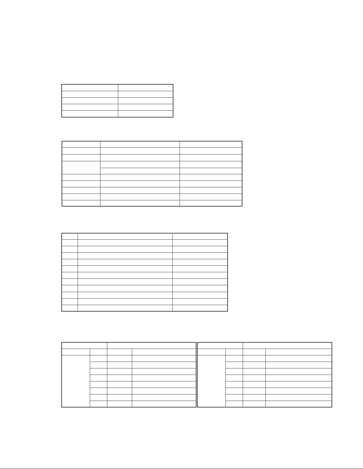
There are 11 main items in the diagnostic menu and some of them have sub-menu items as listed below.
No.
1
2
3
4
5
6
7
8
9
10
11
MAIN MENU
ANALOG THROUGH
DSP THROUGH
AC–3/DTS THROUGH
PRO LOGIC
SPEAKERS SET
EFFECT OFF
/DISPLAY CHECK
MANUAL TEST
FACTORY PRESET
AD DATA CHECK
STATUS
VERSION CHECK
/DSP CPU SUM
/EXIT
SUB MENU
1. MAIN BYPASS
2. DSP 0dB
1. YSS918–SRAM
2. YSS918
3. DSP FULL BIT
1. STATUS (BINARY FORM)
1. CENTER LARGE
2. EFFECT OFF
1. MAIN : SMALL 0dB
2. MAIN : LARGE 0dB
3. MAIN : LARGE –10dB
4. LFE/BASS : MAIN
CENTER : NONE
5. LFE/BASS : MAIN
6. LFE/BASS : SWFR
7. CENTER : NONE
8. CENTER : SMALL
REAR : SMALL
9. FRONT MIX
1. EFFECT OFF
2. VFD DISP OFF
3. VFD DISP ALL
4. CHECKED PATTERN
5. RELEASE DATE
1. ALL
2. MAIN L
3. CENTER
4. MAIN R
5. REAR R
6. REAR L
7. LFE
1. INHIBIT(Inhibit Memory Init)
2. RESERVED (Init. Memory)
1. – – –
2. KEY
3. TUNING SIGNAL
4. DC PROTECTION
5. PS PROTECTION
1. DSP CPU STATUS
2. CHANNEL STATUS
3. VERSION INFORMATION
4. CHECK SUM
5. BSI0 (AC3/DTS)
6. BSI1
7. BSI2
8. BSI3
9. BSI4
10. BSI5
1. MAIN MC CHECK SUM
2. SUB MC CHECK SUM
3. MAIN M.C. VERSION
4. SUB M.C. VERSION
5. PORT INFORMATION
6. EXIT
REMOTE CONTROL CODE (KEY)
7A–88 ("1" [DSP mode])
– – –
7A–89 ("2" [DSP mode])
– – –
– – –
– – –
7A–8A ("3" [DSP mode])
– – –
7A–8B ("4" [DSP mode])
7A–8C ("5" [DSP mode])
7A–8D ("6" [DSP mode])
7A–8E ("7" [DSP mode])
7A–8F ("8" [DSP mode])
7A–90 ("9" [DSP mode])
7A–91 ("0" [DSP mode])
– – –
7A–12 ("ENTER" [DSP mode])
– – –
– – –
– – –
– – –
– – –
– – –
– – –
– – –
– – –
– – –
– – –
– – –
– – –
– – –
– – –
– – –
– – –
– – –
– – –
– – –
– – –
– – –
– – –
– – –
– – –
– – –
– – –
– – –
– – –
– – –
– – –
8
RX-V595a/HTR-5150/RX-V595aRDS
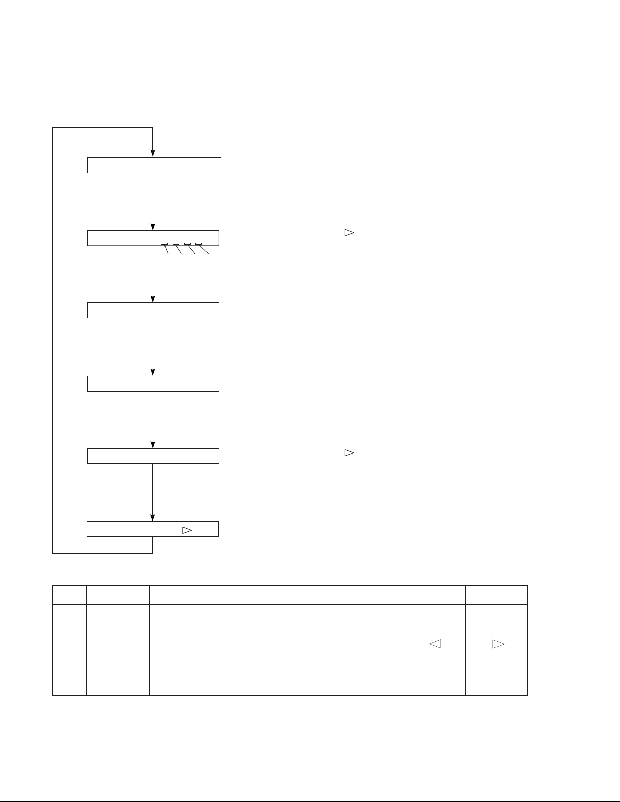
2. BEGINNING AND CANCELLATION
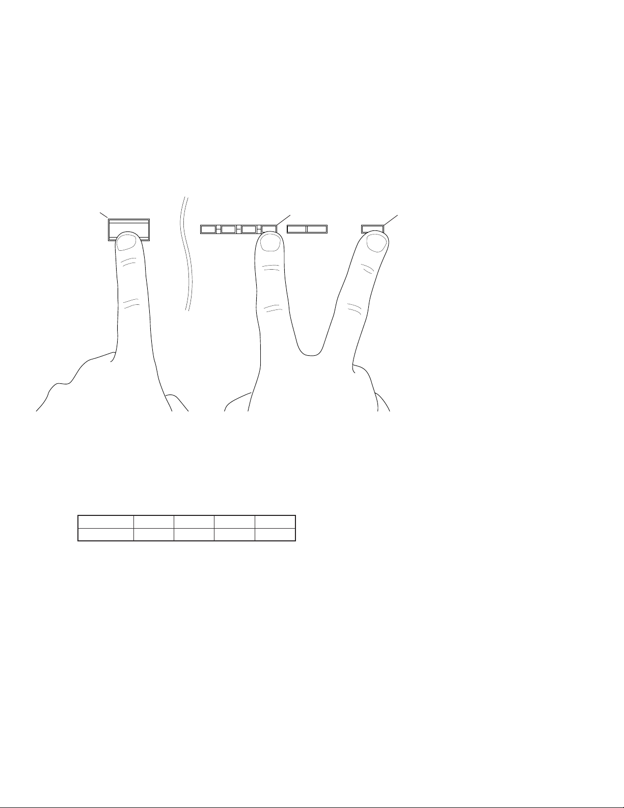
(1) STARTING UP THE FUNCTION AND THE DISPLAY
After starting up, menu No. 1 is selected.
A. How to start diagnostic program
Using the front panel keys of the main unit.
Plug in the AC power cord , and, with Power OFF, hold down the "INPUT MODE" and "FM/AM" keys simultaneously
(Step 1), and then press the "STANDBY/ON" key (Step 2).
Submenu No. 1 of the Diagnosis Main Menu No. 1 will start.
FRONT PANEL
"STANDBY/ON" key
STANDBY/ON
EDIT
TUNING
MODE
FM/AM
MEMORY
MAN'L/AUTO FM AUTO/MAN'L MONO
"FM/AM" key
DOWN UP
TUNING
INPUT MODE
Step2. Press the "STANDBY/ON" key Step1. Hold down the "INPUT MODE"
and "FM/AM" key simultaneously.
B. Settings for start-up of diagnostic program
The settings used when starting the diagnostic program are as follows.
1.
EFFECT LEVEL :
CHANNEL CENTER R SUR L SUR SWFR
LEVEL (dB) 0 0 0 0
"INPUT MODE" key
2.
MUTING : OFF
3.
INPUT (VIDEO) : DVD/LD (DVD/LD)
4.
CENTER SPEAKER : LARGE
5.
REAR SPEAKER : LARGE
6.
MAIN SPEAKER : LARGE
7.
LFE/BASS OUT : SWFR
C. Start-up display
The protection function information appears on the front panel display of the main unit.
9

RX-V595a/HTR-5150/RX-V595aRDS
● FL display at start-up of diagnostic program
When the diagnostic program has started, the history (*2) of the protection function (*1) is displayed. If the protection
function has been activated in the past, the type and voltage value are displayed. After a few seconds the diagnosis
function menu will appear.
(*1) If a faulty condition is detected such as excessive current, a bad power supply or excessive amplifier DC offset,
the Power will be switched OFF automatically.
(*2) The protection records will be cleared when "RESERVED" is selected in diagnosis menu No. 8 and FACTORY
PRESET is engaged.
● History of protection function
Each case of the history of the protection function is displayed as shown below.
1 DVD/LD NO PROTECT
1 DVD/LD I PROTECT
1 DVD/LD PS : 21%
1 DVD/LD DC : 19%
Appears when the protection function has not been activated.
Appears when the current protection function has been activated.
When power is turned on in an abnormal status, the power relay
will come on, protection will operate immediately, and power will
turn off.
Appears when the power protection function has been activated.
For the % value, the voltage at that point is shown by 5V/100%.
When power is turned on in an abnormal status, power will turn off
after half a second.
Appears when the power amp DC protection function has been
activated.
For the % value, the voltage at that point is shown by 5V/100%.
When power is turned on in an abnormal status, power will turn off
after two seconds.
(2) EXITING METHOD
The diagnosis function can be exited by any of the following procedures. Take care with the setting of backup memory
initialization menu (diagnosis No. 8) when releasing the diagnosis function:
1. Select diagnosis menu No. 11/submenu No. 6 "EXIT".
2. Press the "STANDBY/ON" key on the main unit or "STANDBY" key on the remote control to turn power off.
10
RX-V595a/HTR-5150/RX-V595aRDS
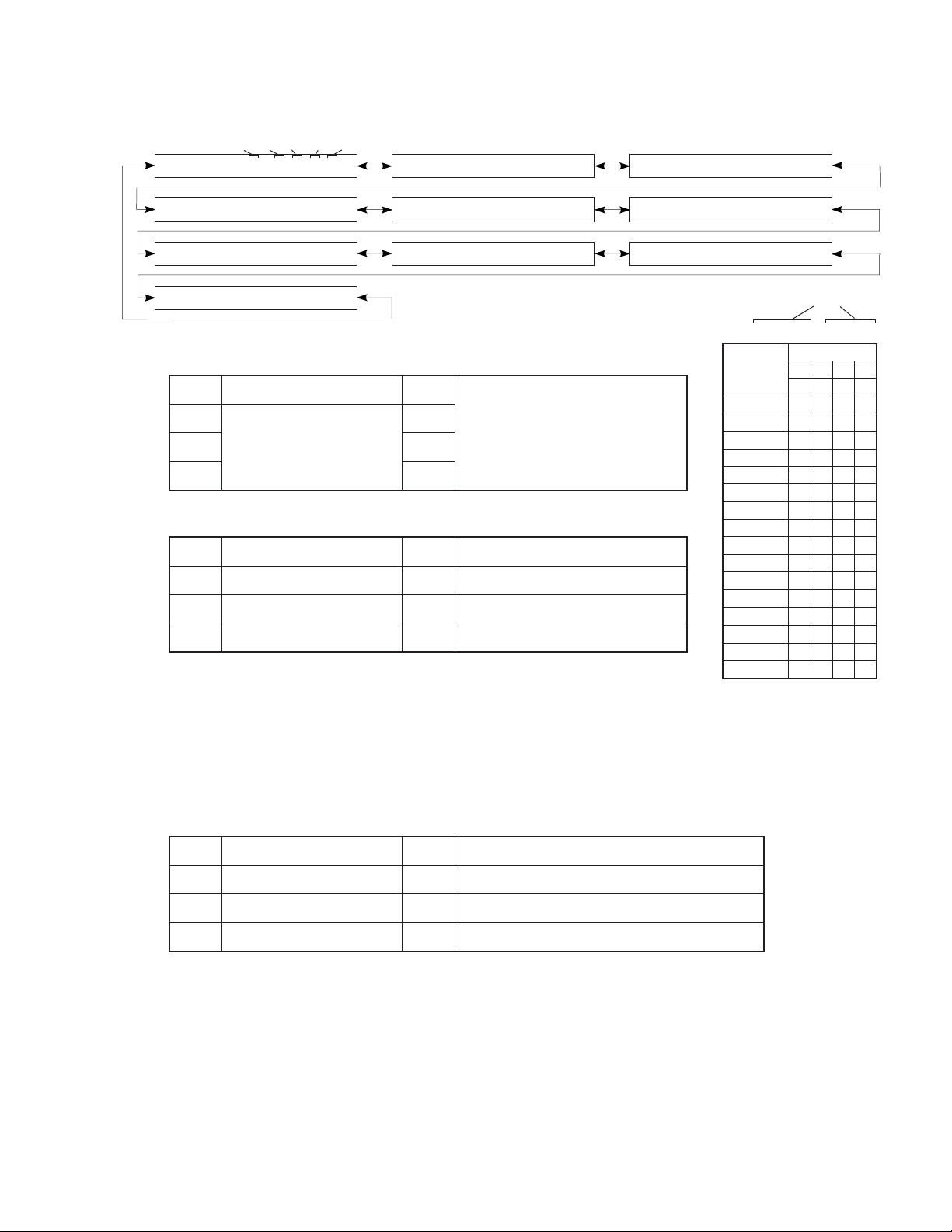
3. OPERATION AND DISPLAY WHEN STARTING DIAGNOSIS FUNCTION
(1) Selection of diagnostic menu
The diagnostic menu and the sub-menu can be selected by using the front panel keys of the main unit or the remote
control unit.
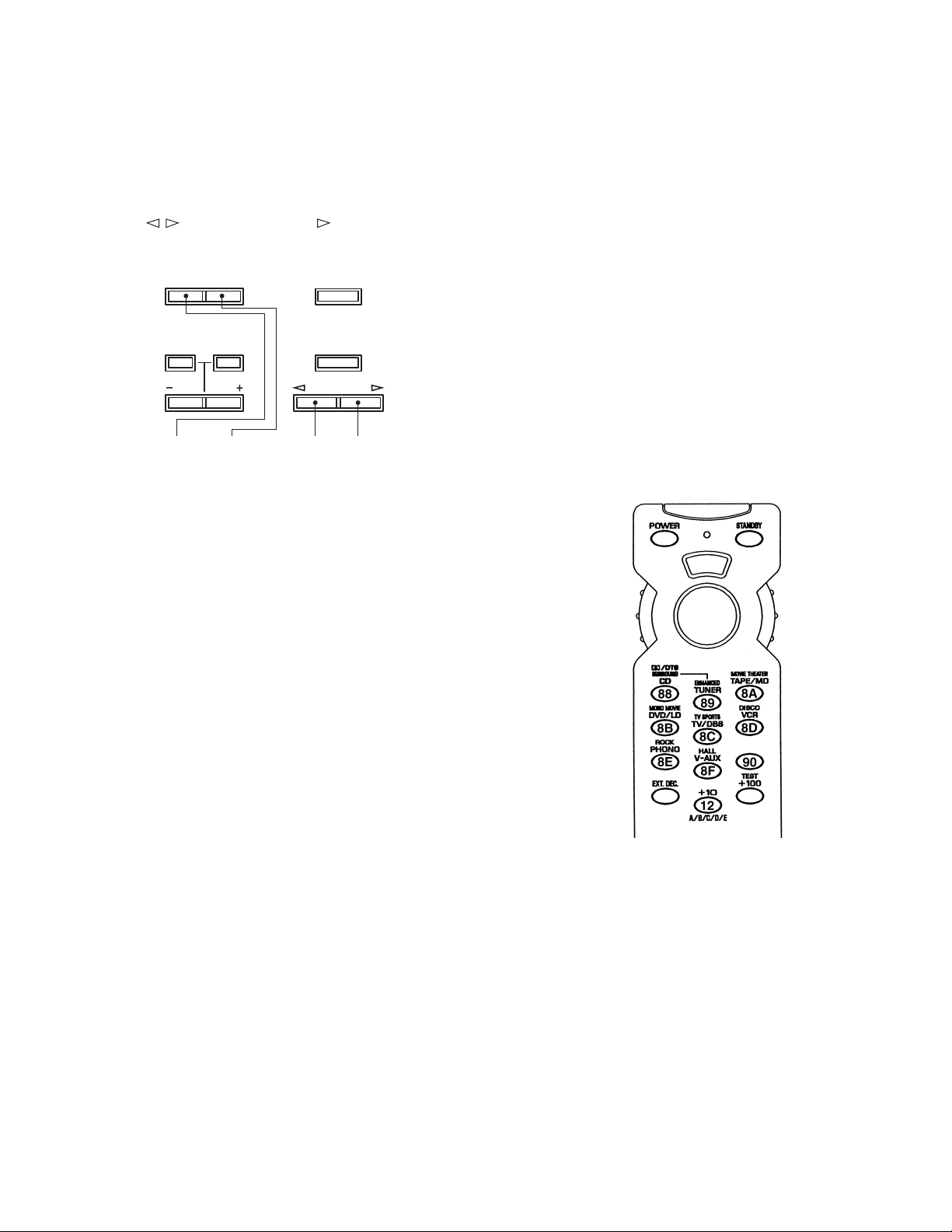
● Selection by using the front panel keys
The main menu can be changed cyclically by using the "TUNING UP/DOWN" keys, and the submenu, by using the
"PROGRAM / " keys. The "UP" or " " key will increase the main or submenu number.
FRONT PANEL
DOWN UP
TUNING
INPUT MODE
TIME/
LEVEL
Reverse Forward Reverse Forward
SET
MENU
Main menu Sub menu
EFFECT
PROGRAM
● Selection by using the remote control unit
The remote control codes in the menu list (see right column
on page 8) correspond to the DSP program test and effect keys.
See the figure on the right.
S
P
D
7A
(2) Other functions available while diagnosis function is active
Listed below are the other functions available while the diagnosis function is active.
• Selecting input source (Tape monitor/Ext. decoder)
• Adjusting effect level (Center, Rear, Subwoofer)
• Adjusting master volume
• Muting on/off
• Power on/off
(3) Diagnosis default status
When not otherwise specified, default settings and values in each menu are as follows:
• All “SPEAKERS” : LARGE
• ALL electronic VRs : 0dB
• DYNAMIC RANGE : MAX
• LFE LEVEL : 0dB (DOLBY DIGITAL, DTS)
• CENTER DELAY : 0ms
11
4. CONTENTS OF DIAGNOSIS FUNCTION
This section describes the contents of the self diagnosis function in detail.
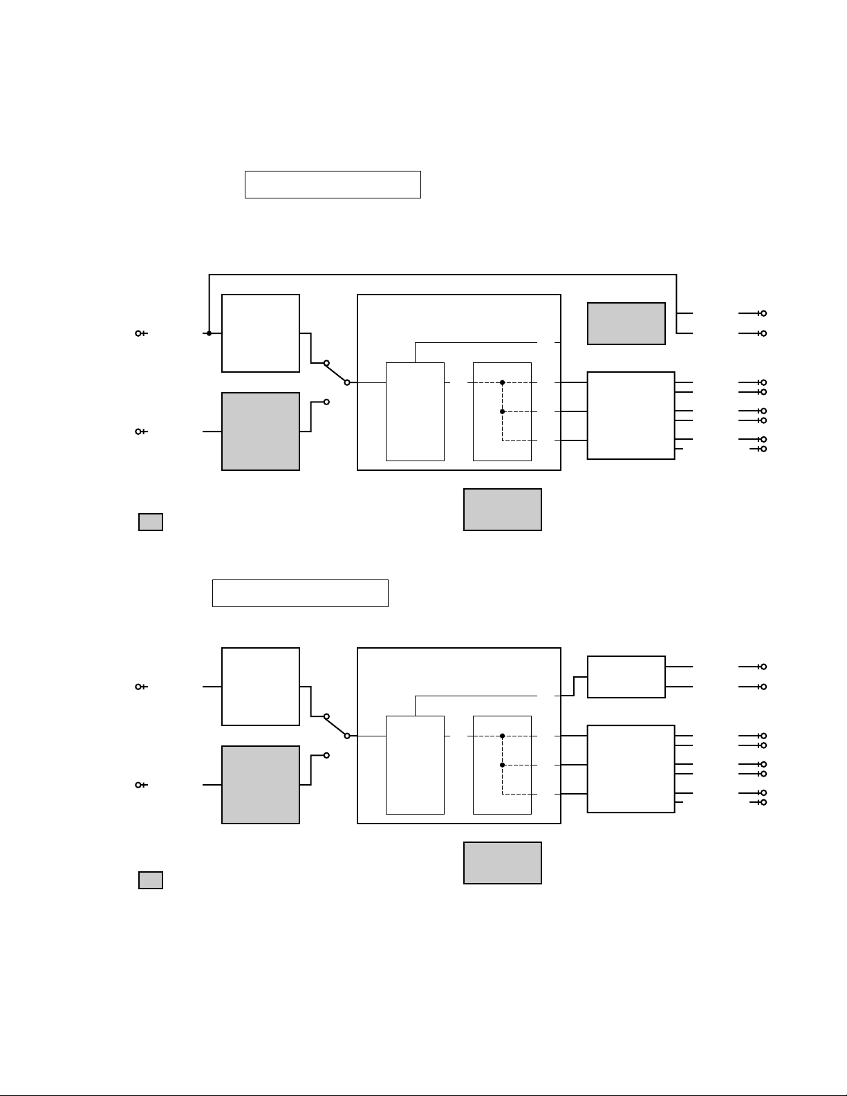
No.1 ANALOG THROUGH
The input is fixed to analog (A/D). There are two submenus.
1. MAIN BYPASS
The MAIN L/R signals bypass the analog circuits to be output.
For CENTER/LFE, FRONT L/R and REAR L/R, the MAIN L/R signals via the DSP are output without
being processed (through). (Remote control code 7A-88: "1" key [DSP mode])
: This shows that the device is not operating.
2. DSP 0dB
MAIN L/R, CENTER/LFE, FRONT L/R and REAR L/R pass through the DSP without being
processed.
: This shows that the device is not operating.
DIR2
CODEC.DA
AK4526A
YM3436
CODEC.AD
AC3D2av(YSS918)
AK4526A
DECODER
DA
AK4320
1M SRAM
DSP
ANALOG IN
L/R L/R
FRONT R
REAR L
REAR R
CENTER
SUBWOOFER
L/R
L/R
L/R
DIGITAL IN
FRONT L
MAIN R
MAIN L
DIR2
CODEC.DA
AK4526A
YM3436
CODEC.AD
AC3D2av(YSS918)
AK4526A
DECODER
DA
AK4320
1M SRAM
DSP
ANALOG IN
L/R L/R
FRONT R
REAR L
REAR R
CENTER
SUBWOOFER
L/R
L/R
L/R
DIGITAL IN
FRONT L
MAIN R
MAIN L
1 DVD/LD DSP 0DB
1 DVD/LD MAIN BYPAS
• INPUT : DVD/LD (Analog signal)
(Lch and Rch, 1KHz, –20dBV)
• OUTPUT : SPEAKERS
MAIN L : 23.8 dBV REAR L : 23.7 dBV
MAIN R : 23.8 dBV REAR R : 23.7 dBV
CENTER: 23.7 dBV
• INPUT : DVD/LD (Analog signal)
(Lch and Rch, 1KHz, –20dBV)
• OUTPUT : SPEAKERS
MAIN L : 23.7 dBV REAR L : 23.6 dBV
MAIN R : 23.7 dBV REAR R : 23.6 dBV
CENTER: 23.6 dBV
RX-V595a/HTR-5150/RX-V595aRDS
12
RX-V595a/HTR-5150/RX-V595aRDS
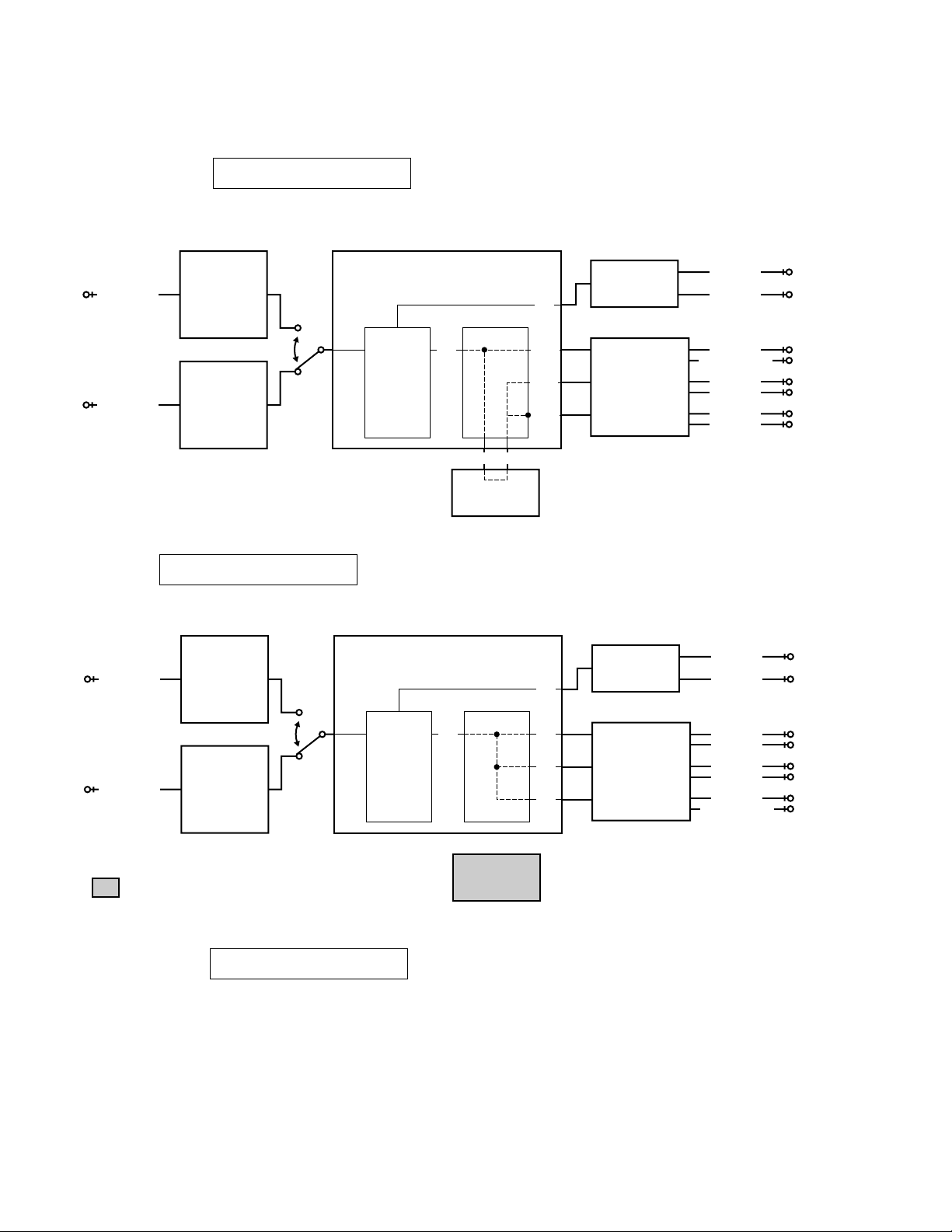
No.2 DSP THROUGH
The input is automatically discriminated by signal detection and switched with priorities AC-3 (DOLBY
DIGITAL)>DTS Digital Surround>Audio>analog. There are the following three submenus.
1. YSS918-SRAM
2 DVD/LD YSS918SRAM
MAIN L/R are input to the DSP via AC3D2av, pass through SRAM, and are then output to all channels without
being processed. (Remote control code 7A-89: "2" key [DSP mode])
CODEC.AD
ANALOG IN
AC3D2av(YSS918)
L/R
DA
AK4320
MAIN L
MAIN R
AK4526A
DECODER
DIR2
DIGITAL IN
YM3436
2. YSS918
MAIN L/R are input to the DSP via AC3D2av, and then output to all channels without being processed.
2 DVD/LD YSS918
L/R
DSP
L/R L/R
1M SRAM
L/R
L/R
L/R
CODEC.DA
SUBWOOFER
AK4526A
• INPUT : DVD/LD (Analog signal)
• OUTPUT : SPEAKERS
(Lch and Rch, 1KHz, –20dBV)
MAIN L : 23.7 dBV REAR L : 23.5 dBV
MAIN R : 23.7 dBV REAR R : 23.5 dBV
CENTER: 23.6 dBV
CENTER
REAR L
REAR R
FRONT L
FRONT R
CODEC.AD
ANALOG IN
AC3D2av(YSS918)
DA
AK4320
L/R
AK4526A
DECODER
DIR2
DIGITAL IN
L/R
DSP
L/R
L/R
L/R
CODEC.DA
AK4526A
YM3436
• INPUT : DVD/LD (Analog signal)
: This shows that the device is not operating.
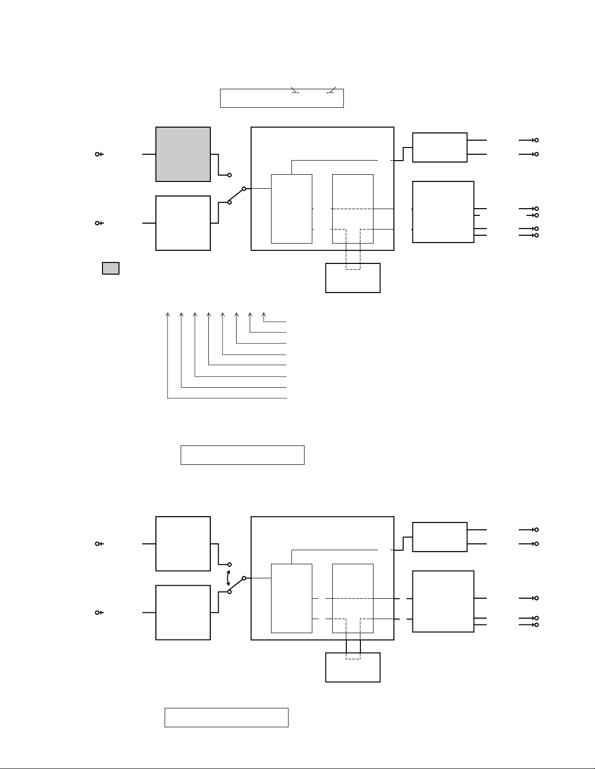
3. DSP FULL BIT
1M SRAM
2 DVD/LD DSP FULL
• OUTPUT : SPEAKERS
MAIN L/R are input to the DSP via AC3D2av, and then output to all channels without being processed.
The head margin is disabled, and DSP outputs digital full-bit signals.
Same as the above menu, except that the digital data is output to DA with full bits.
• INPUT : DVD/LD (Analog signal)
• OUTPUT : SPEAKERS
(Lch and Rch, 1KHz, –20dBV)
MAIN L : 23.8 dBV REAR L : 23.8 dBV
MAIN R : 23.8 dBV REAR R : 23.8 dBV
CENTER: 23.8 dBV
(Lch and Rch, 1KHz, –20dBV)
MAIN L : 13.8 dBV REAR L : 22.8 dBV
MAIN R : 13.8 dBV REAR R : 22.8 dBV
CENTER: 16.8 dBV
MAIN L
MAIN R
FRONT L
FRONT R
REAR L
REAR R
CENTER
SUBWOOFER
13
RX-V595a/HTR-5150/RX-V595aRDS
No.3 AC-3/DTS THROUGH
The input is digital signal only. AC-3 (DOLBY DIGITAL) or DTS Digital Surround decoding operation is executed,
according to the input source.
bit 0 bit 7
1. STATUS(BINARY FORM)
3 DVD/LD 3T00000001
AC-3 (DOLBY DIGITAL) decoded signals are output to each channel via AC3D2av.
CODEC.AD
ANALOG IN
AC3D2av(YSS918)
L/R
AK4526A
DSP
C/LFEC/LFE
LS/RSLS/RS
DIGITAL IN
DIR2
DECODER
DOLBY DIGITAL
or
PRO LOGIC
or
DTS
YM3436
: This shows that the device is not operating.
AC-3 Status Info. : bit7 6 5 4 3 2 1 0
(Invalid in DTS) 1 0 0 00000
IEC958 digital data bit
IEC958 commercial-use device bit
IEC958 digital format error
Demodulator muting (without RF signal)
1 for audio other than PCM linear audio
1 during red DTS lock
1 during DTS decode OK
1 during AC-3 decode OK
1M SRAM
DA
AK4320
CODEC.DA
AK4526A
MAIN L
MAIN R
CENTER
SUBWOOFER
REAR L
REAR R
No.4 PRO LOGIC
The input is automatically discriminated by PCM Audio>analog. DTS Digital Surround is disabled.
The submenu is switched between PRO LOGIC (AUTO BALANCE OFF) and EFFECT OFF.
1. CENTER LARGE
4 DVD/LD P. LGC C:L
The input is automatically detected whether it is PCM Audio or analog. With analog, PCM Audio or AC-3 (DOLBY DIGITAL) 2/0 input, the L, R, C and S signals are PRO LOGIC decoded and output. With AC-3 (DOLBY DIGITAL) other
than 2/0, PRO LOGIC does not operate, and AC-3 (DOLBY DIGITAL) playback is executed. (Remote control code
7A-8A: "3" key [DSP mode])
CODEC.AD
ANALOG IN
AC3D2av(YSS918)
DA
AK4320
L/R
AK4526A
DECODER
DSP
CODEC.DA
DIR2
DIGITAL IN
YM3436
2. EFFECT OFF
MAIN L/R are bypassed and output.
4 DVD/LD EFFECT OFF
DOLBY DIGITAL
or
PRO LOGIC
or
DTS
C
S
1M SRAM
C
S
AK4526A
• INPUT : DVD/LD (Analog signal)
(Lch and Rch, or Lch only, 1KHz, –20dBV)
• OUTPUT : SPEAKERS
(INPUT : Lch and Rch ) (INPUT : Lch only)
MAIN L : –15.4 dBV REAR L : 23.8 dBV
MAIN R : –14.2 dBV REAR R : –25.0 dBV
CENTER: 26.6 dBV CENTER : –12.5 dBV
REAR L : –6.0 dBV REAR L : –6.0 dBV
REAR R : –6.5 dBV REAR R : –6.2 dBV
CENTER
REAR L
REAR R
MAIN L
MAIN R
14
RX-V595a/HTR-5150/RX-V595aRDS
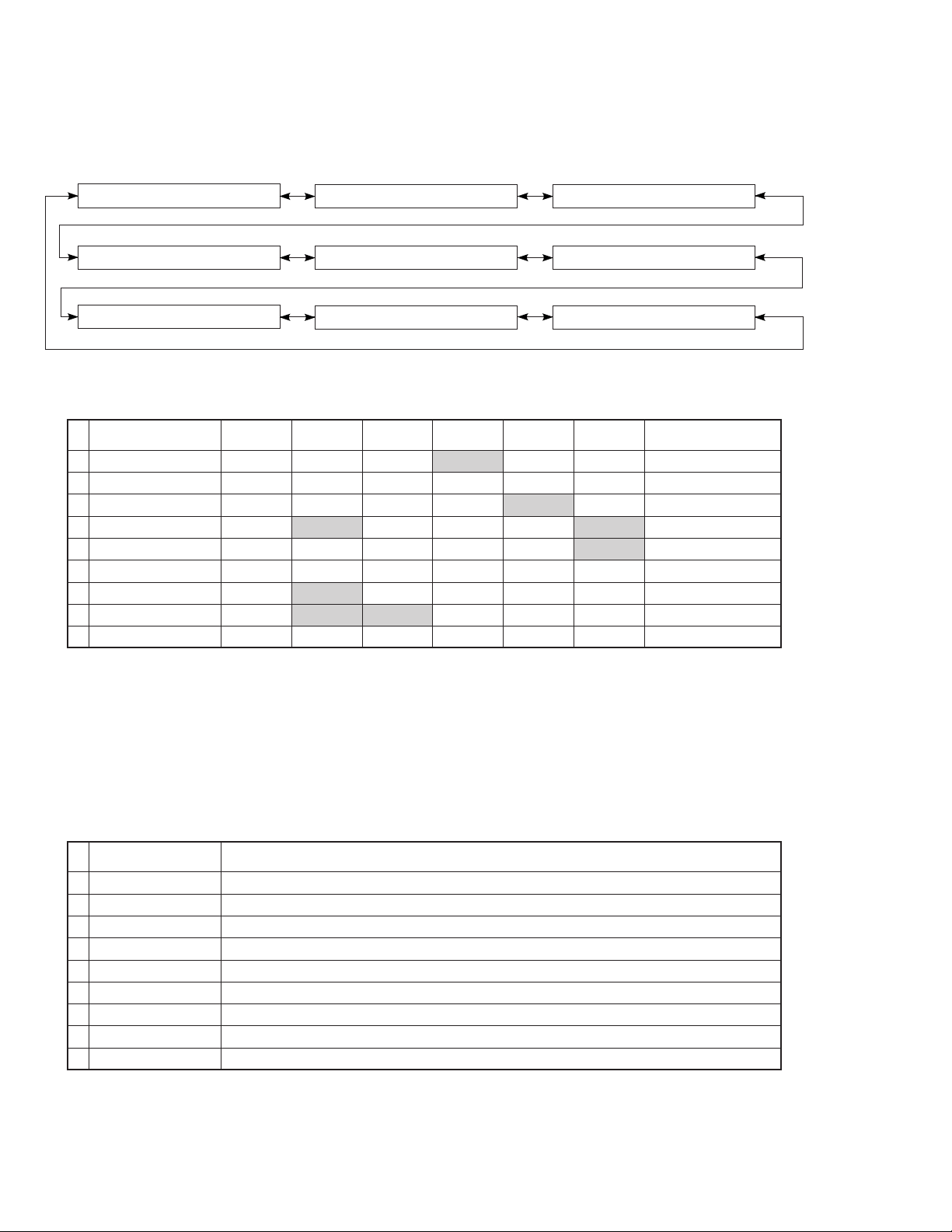
No.5 SPEAKERS SET
The input is automatically discriminated by AC-3(DOLBY DIGITAL)>DTS Digital Surround>PCM Audio>analog.
There are the following 9 submenu items: The signal from the DSP block is normally in the effect off status for menu
items 1-4. For other menu items, the same signal as in 2. DSP THROUGH: YSS918 menu is output.
5 DVD/LD MAIN:S 0DB
5 DVD/LD B:MAIN C:N
5 DVD/LD C:NONE
5 DVD/LD MAIN:L 0DB
5 DVD/LD LFE/B:MAIN
5 DVD/LD C:S REAR:S
5 DVD/LD MAIN:L —10
5 DVD/LD LFE/B:SWFR
5 DVD/LD FRONT MIX
The analog switches in each submenu are set as follows:
SUB MENU
1 MAIN:S 0DB 7A-8B LARGE LARGE SMALL 0dB SWFR MAIN L/R
2 MAIN:L 0DB 7A-8C LARGE LARGE LARGE 0dB SWFR MAIN L/R
3 MAIN:L -10 7A-8D LARGE LARGE LARGE -10dB SWFR MAIN L/R
4 B:MAIN C:N 7A-8E NONE LARGE LARGE 0dB MAIN MAIN L/R
5 LFE/B:MAIN 7A-8F LARGE LARGE LARGE 0dB MAIN LFE -> L/R
6 LFE/B:SWFR 7A-90 LARGE LARGE LARGE 0dB SWFR LFE -> SWFR
7 C:NONE 7A-91 NONE LARGE LARGE 0dB SWFR CENTER -> L/R
8 C:S REAR:S SMALL SMALL LARGE 0dB SWFR CENTER/REAR
9 FRONT MIX 7A-12 LARGE LARGE LARGE 0dB SWFR FRONT -> L/R
REMOTE
CODE
CENTER SP
MAIN SPREAR SP
MAIN
LEVEL
OUTPUTLFE/BASS
LARGE: Mode in which speakers with high bass-sound pla ybac k capability (large unit) are used. Full frequency band
widths is output.
SMALL: Mode in which speakers with low bass-sound playback capability (small unit) are used. Frequncies below 90 Hz
are mixed with the channel specified by LFE/BASS.
NONE: Mode in which center speaker is not used. The center audio signal is reduced by 3 dB and mixed into MAIN L/R.
LFE/B: MAIN
:Mode in which subwoofer speaker is not used. The subwoofer audio signal is reduced by 4.5 dB and mixed into
MAIN L/R. But because of the phase difference, the MAIN L/R output is not simply summed.
Purpose of the submenu as follows:
SUB MENU PURPOSE
1 MAIN:S 0DB Verification of the High and low pass filter response and gain in the bass redirection mode.
2 MAIN:L 0DB Reference of the sub menu No. 1 and 2.
3 MAIN:L -10 Verification of the effect in the main level function.
4 B:MAIN C:N Verification of the mixing circuit effect to the main channel.
5 LFE/B:MAIN Verification of the bass mix gain.
6 LFE/B:SWFR Verification of the LFE maximum output.
7 C:NONE Verification of the center mix gain.
8 C:S REAR:S Verification of the high and low pass filter response and gain in the bass redirection mode.
9 FRONT MIX Verification of the front mix gain.
15
RX-V595a/HTR-5150/RX-V595aRDS
No.6 DISPLAY CHECK
Check program for FL display. The display status will change as follows with submenu operation. The signal is
processed with EFFECT OFF.
6 DVD/LD DISP CHECK
Initial display All segments turn off All segments turn on
6 DVD/LD 9902161625
Segments light in lattice formRelease date display
All segments are turned on and off to detect defects in the FL driver and FL display segments. Then the FL driver
operation is checked by the dimmer control.
Finally, all segments are turned on and off alternately (in lattice form), to check for a short-circuit between adjacent
segments.
No.7 MANUAL TEST
The noise generator built into the DSP outputs test noise from the channel specified by the submenu.
7 DVD/LD TEST ALL
7 DVD/LD TEST MAINR
7 DVD/LD TEST MAINL
7 DVD/LD TEST REARR
7 DVD/LD TEST CNTR
7 DVD/LD TEST REARL
7 DVD/LD TEST LFE
No.8 FACTORY PRESET
The initialization of the back-up RAM, which contains effect level, DSP program, set menu contents, etc. is reserved
or inhibited. The Signal is processed with EFFECT OFF.
8 DVD/LD PRESET INH
8 DVD/LD PRESET RES
Caution : Before setting to the PRESET RESERVED, write down the existing preset memory contents of the Tuner in
a table as shown below. (This is because setting to the PRESET RESERVED will cause the memory contents
to be as factory set, i.e., all the preset memory by the user will be erased.)
Page P1 P2 P3 P4 P5 P6 P7 P8
A
B
C
D
E
1. INHIBIT: Inhibits initialization of the back-up RAM.
Specify this option protect user set Values.
2. RESERVED: Reserve to initialization of the back-up RAM.
(The RAM is actually initialized when power
is turned on next time.) Specify this option
at the factory preset or to reset the RAM.
For the contents of the initialization, see page 20.
The protection data is also reset.
16
RX-V595a/HTR-5150/RX-V595aRDS
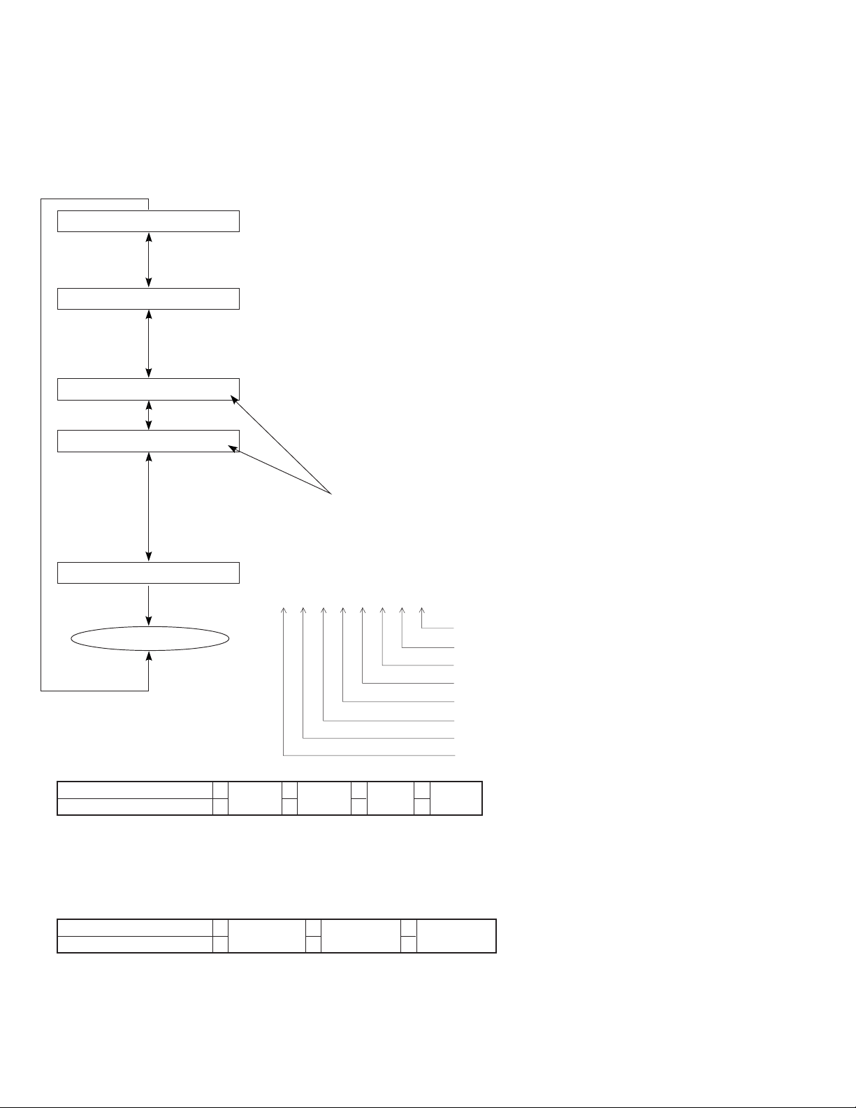
No.9 AD DATA CHECK
The A/D conversion values of the main CPU which detects key scan, protection, etc. are displayed in % (100%: 5V).
All signal processing before this menu is executed will be held.
The keys on the main unit cannot be operated to detect the values of all keys in the K1/K2/K3/K4 and SI.
Operating the "PROGRAM" key and turning the rotary encoder (input selector on the main unit) will switch the submenu.
9 DVD/LD AD DATACHK
9 DVD/LD K99999999
K1 K2 K3 K4
9 DVD/LD SI 0
9 DVD/LD DC 7
9 DVD/LD
PS 40
Press the "PROGRAM "key.
K1/K2/K3/K4: Panel key on main unit
See Table 1.
Turning the rotary encoder.
SI: Tuner signal level
Turning the rotary encoder.
DC: DC protection value
(normal value: 1-13)
Press the "PROGRAM "key.
PS: Power voltage protection value
(normal value: 28-54)
17
Press the "PROGRAM "key.
Table 1
AD Value
K1
K2
K3
K4
0112336516784
TIME/
LEVEL
TAPE/MD MON
/EXT. DECODER
7
A/B/C/D/E
SET
MENU
TUNING
DOWN
8
1
–
TUNING
UP
MEMORY
2
+
INPUT MODE
EDIT
3
EON
EFFECT
TUNING
MODE
4
PTY SEEK
MODE
PROGRAM
FM/AM
5
Cautions:
1.If K1/K2/K3/K4 are more than ±4% from the reference values, normal operation will not be executed.
2.If DC and PS are outside the normal values, the protection function will operate and power will turn off.
PTY SEEK
START
PROGRAM
RDS
MODE
6
RX-V595a/HTR-5150/RX-V595aRDS
No.10 STATUS FROM DSP MICOM
The status data from the DSP microprocessor is sequentially displayed in a hexadecimal number.
All signal processing before this menu is executed will be held.
1st 2nd 3rd 4thSTATUS
10 DVD/LD 0 00000000
10 DVD/LD 1 00000000
10 DVD/LD 2 00000000
10 DVD/LD 3 00000000
10 DVD/LD 6 00000000
10 DVD/LD 9 00000000
[STATUS 0]
<1st Byte>
acmod: If it is 1000B or more with DTS 7.1 signal, the DSP block will be muted.
<2nd Byte>
[Note]
IEC958: Standard to identify the PCM bit stream signal. Digital format error refers to a digital signal with the
sampling frequency undefined (neither 44.1k, 32k nor 48k). Since the operation of each device cannot be
assured at fs outside specifications, the sub-microprocessor handles this status as the forced analog mode
(ignored even if decoding is OK from the detection terminal level), and selects the signal from the analog input
terminal. Since the sub-microprocessor transmits 000B (analog) for STATUS#0 bits 4-6 to the main
microprocessor, the main microprocessor visually operates in the same way as with digital unlocking.
10 DVD/LD 4 00000000
10 DVD/LD 7 00000000
bit7 Mute request bit3 acmod
bit6 fs bit2
bit5 000B:Analog 001B:32kHz
bit4 bit0
bit7 AC-3 decode OK bit3 Demodulator muting (without RF signal)
bit6 DTS decode OK bit2 IEC958 digital format error
bit5
bit4
010B:44.1kHz 011B:48kHz
Others:Don't care
Red DTS record
(Flashes and lights)
1 for audio other than PCM
linear audio
0000B:1+1 0001B:1/0
0010B:2/0 0011B:3/0
0100B:2/1 0101B:3/1
bit1
0110B:2/2 0111B:3/2
1000B:7.1
bit1 IEC958 commercial use device bit
bit0 IEC958 digital data bit
10 DVD/LD 5 00000000
10 DVD/LD 8 00000000
Indicate
bit 7 6 5 4 3 2 1 0
0
0
Indicate bit
3210
7654
0 0000
1 0001
2 0010
3 0011
4 0100
5 0101
6 0110
7 0111
8 1000
9 1001
A 1010
B 1011
C 1100
D 1101
E 1110
F1111
<3rd Byte>
bit7 AC3 KARAOKE bit3 On-board write mode
bit6 DIR2 LOCKN bit2 The number of digital inputs is 2 (equivalent to 595)
bit5 DIR2 ERR bit1 DSP is AC3D2 (DTS present)
bit4 AC3D MUTE bit0 RF DEM present
<4th Byte> Always “00”
[STATUS 1] IEC958 channel status bits 00-31 available from DIR2
<1st-byte> bits 00-07
<2nd-byte> bits 08-15
<3rd-byte> bits 16-23
<4th-byte> bits 24-31
[STATUS 2] 4-byte ASCII code of sub CPU version data
[STATUS 3] Displays the check sum of sub microprocessor program area with ASCII 4 bytes in a hexadecimal number.
[STATUS 4] Displays the bit stream information contained in AC-3(DOLBY DIGITAL)/DTS Digital Surround signal from the
first byte.
[STATUS 5-9] Displays the bit stream information contained in AC-3(DOLBY DIGITAL) signal from the first byte.
18
RX-V595a/HTR-5150/RX-V595aRDS
No.11 CPU VERSION/CHECK SUM/PORT INFO/EXIT DIAG
The check sum, version and port setting of main CPU/DSP CPU are displayed.
The signal is EFFECT OFF.
Operating the submenu will finish self-diagnosis, and ordinary operation mode will be restored.
The suffix letter ("B" in the following) of version indication is for compatibility of communications between the main and
DSP microprocessors.
Combining microprocessors with different suffixes will make normal operation impossible.
11 DVD/LD M-SM:XXXXX
11 DVD/LD S-SM:XXXXX
11 DVD/LD M-VER:Z04B
11 DVD/LD S-VER:Z08B
11 DVD/LD P:00000000
Main microprocessor check sum
DSP microprocessor check sum
Main microprocessor version
DSP microprocessor version
One suffix letter is for compatibility of communications between the main
and DSP microprocessors.
* Use microprocessors with the same suffix.
bit76543210
00000000
EXIT
✽1
Tuner Mode V2 (Port 96) 0*11*20*31*4
Tuner Mode V1 (Port 95) 0011
*1 AM:531–1611kHz/9kHz FM: 76.0–90.0MHz/100kHz (J model)
*2 AM:530–1710kHz/10kHz FM: 87.5–107.9MHz/200kHz (U, C models)
*3 AM:531–1611kHz/9kHz FM: 87.5–108.0MHz/50kHz (R, T, A, B, G, L models)
*4 AM: 530-1710kHz/10kHz FM:87.5-108.0 MHz/100kHz (R, T models)
✽2
Model Type DSP-A(Port 83) 1 DSP-A595a 0 RX-V595aRDS 0 RX-V595a
Model Type RDS(Port 70)
Hi=1, Low=0
Hi=1, Low=0
01 0
HTR-5150
Always absent (0)
Always absent (0)
Tuner Mode V1 (✽1)
Tuner Mode V2 (✽1)
Always absent (0)
Always absent (0)
Model Type RDS (✽2)
Model Type DSP-A (✽2)
19
■ FACTORY PRESET
All of the system settings are iniially set from the factory as follows.
●
INPUT (VIDEO)
DVD/LD (DVD/LD)
●
EFFECT LEVEL
EFFECT CHANNEL PRESET VALUE
CENTER 0 dB
RIGHT SURROUND 0 dB
LEFT SURROUND 0 dB
SUBWOOFER 0 dB
●
DSP PROGRAM
INPUT DSP PROGRAM DELAY PRESET VALUE
V-AUX DOLBY PRO LOGIC 20m
VCR PRO LOGIC ENHANCED 20ms
DVD/LD 70mm MOVIE THEATER 20ms
DIGITAL/DTS MOVIE THEATER 16ms
TV/DBS TV SPORTS 9ms
TAPE/MD ROCK CONCERT 49ms
TUNER DISCO 40ms
CD ROCK CONCERT 16ms
PHONO CONCERT HALL 44ms
●
SET MENU
No. SET MENU PRESET VALUE
8. DTS LFE LEVEL [DTS LFE] 0 dB
7. DYNAMIC RANGE [D. RNG] MAX
6. DOLBY DIGITAL LFE LEVEL [D. D. LFE] 0 dB
1. CENTER SPEAKER [CNTR>] LARGE
2. REAR SPEAKER [REAR>] LARGE
3. MAIN SPEAKER [MAIN>] LARGE
4. LFE/BASS OUT [BASS>] SW (SUBWOOFER)
5. MAIN LEVEL [M. LVL>] NRML (NORMAL)
9. CENTER DELAY [C. DELAY] 0ms
11.
10.
INPUT MODE (TV/DBS) [INPUT] AUTO
MEMORY GUARD [GUARD] OFF
●
PRESET STATIONS
STATION FM FACTORY PRESET DATA (MHz)
PAGE NO. U, C R, T, A, B, G, L
1 87.5 87.5
2 90.1 90.1
3 95.1 95.1
A/C/E 4 98.1 98.1
5 107.9 108.0
6 88.1 88.1
7 106.1 106.1
8 107.9 108.0
STATION AM FACTORY PRESET DATA (kHz)
PAGE NO. U, C, R R, T, A, B, G, L
1 630 630
2 1080 1080
3 1440 1440
B/D 4 530 531
5 1710 1611
6 900 900
7 1350 1350
8 1400 1404
RX-V595a/HTR-5150/RX-V595aRDS
20
RX-V595a/HTR-5150/RX-V595aRDS
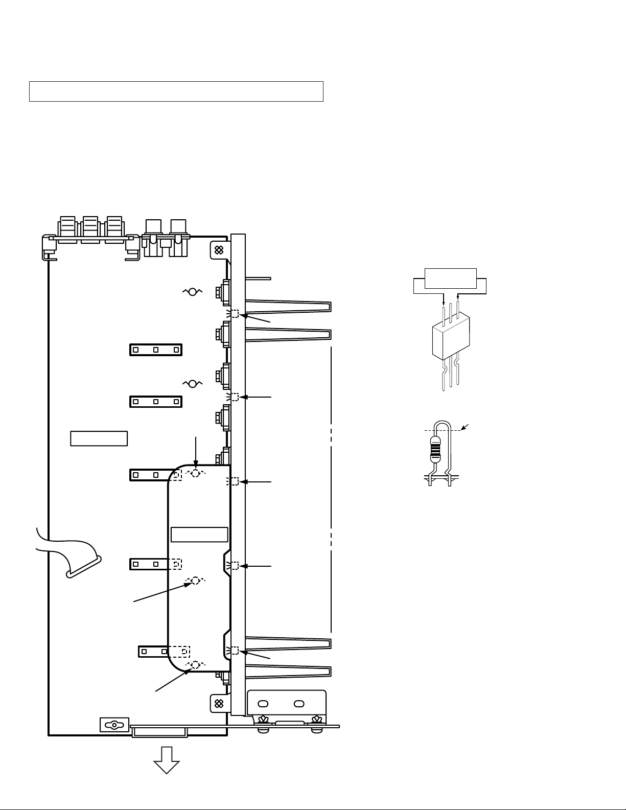
■ AMP ADJUSTMENT
Confirmation of Idling Current of Main Amplifier
Right after power is turned on, confirm that the voltage across the
•
terminals of R688(Main Lch),R690(Main Rch), R692(Center),
R694(Rear Lch), R696(Rear Rch) are between 0.1mV and 5.0mV.
If it exceeds 5.0mV, open (cut off) R571 (Main Lch), R577 (Main
•
Rch), R589 (Center), R595 (Rear Lch), R583 (Rear Rch) and
reconfirm the voltage again.
Confirm that the voltage is 0.25mV ~ 15.0mV after 60 minutes.
•
R583
Q523
R692
R595
R696
Q525
R688(Lch)
R690(Rch)
R692(Cch)
R694(RLch)
R696(RRch)
0.1mV ~ 5.0mV
(DC)
MAIN (1)
R577
R694
R690
R688
R571
R589
MAIN (7)
Q524
Q522
Q521
R571(Lch)
R577(Rch)
R589(Cch)
R595(RLch)
R583(RRch)
Note)
•
•
Cut off
If R571, R577, R589, R595 and
R583 have already been cut off
and idling current does not flow,
reconnect R571, R577, R589,
R595 and R583.
Q521 ~ Q525 are transistors for
temperature correction.
Apply silicone grease to contact
surface with the heat sink.
21
Front Panel
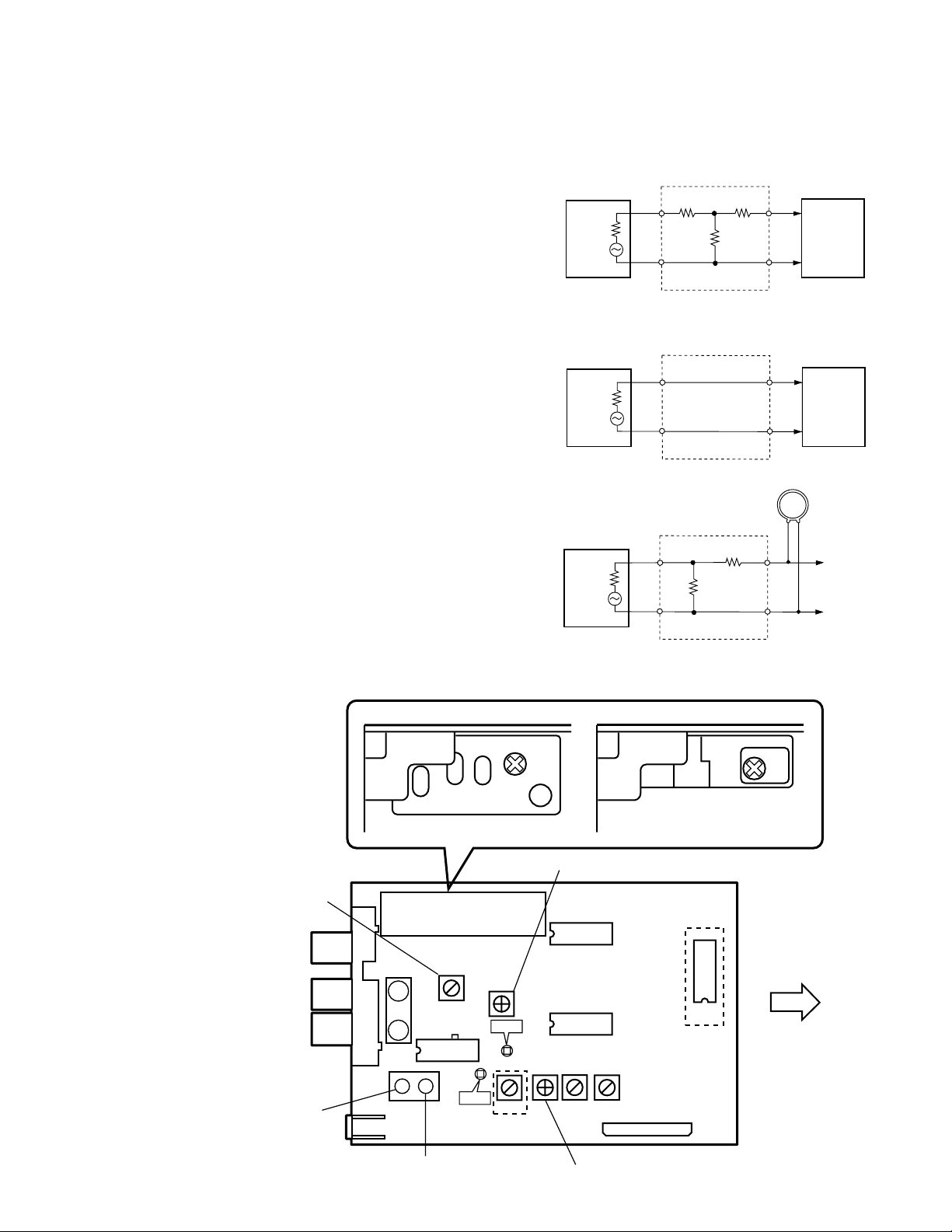
■ TUNER ADJUSTMENT
RX-V595a/HTR-5150/RX-V595aRDS
●Measuring Instruments
1) FM signal generator (FM SG)
2) Stereo signal generator (SSG)
3) AM signal generator (AM SG)
4) Distortion meter (DIST. M)
5) AC Voltmeter (ACVM)
6) DC Voltmeter (DCVM)
7) Oscilloscope
8) Low pass filter (YLF-15, fc=15kHz)
9) Oscillator
●Dummy antenna
E1
FM SG
(50Ω)
E2 (dB) = E1 (dB) -6 (dB)
E1
FM SG
(75Ω)
AM SG
(50Ω)
FM dummy antenna
10Ω 45Ω
60Ω
FM dummy antenna
E2 (dB) = E1 (dB)
AM dummy antenna
10KΩ
50Ω
E2
E2
RECEIVER
(75Ω)
RECEIVER
(75Ω)
AM ANT
GND
●Test point
AM
SENSITIVITY
ADJ.
FM ANT
GND
AM ANT
MONAURAL
DISTORTION ADJ.
(ANTENNA)
T1
PK2
PK1
FRONT END
T2
16
IC1
TP1
A, B, G, L
models only
VR1
TP2
T3
IFT
SIGNAL METER ADJ.
IC2
IC3
VR2
T4
T5
CB4
IFT
A, B, G, L modelsU, C, R, T models
IC4
B, G models only
Front
Panel
DISCRIMINATOR
BALANCE ADJ.
(FRONT)
SEPARATION
ADJ.
22
 Loading...