

Page 1
Preparation
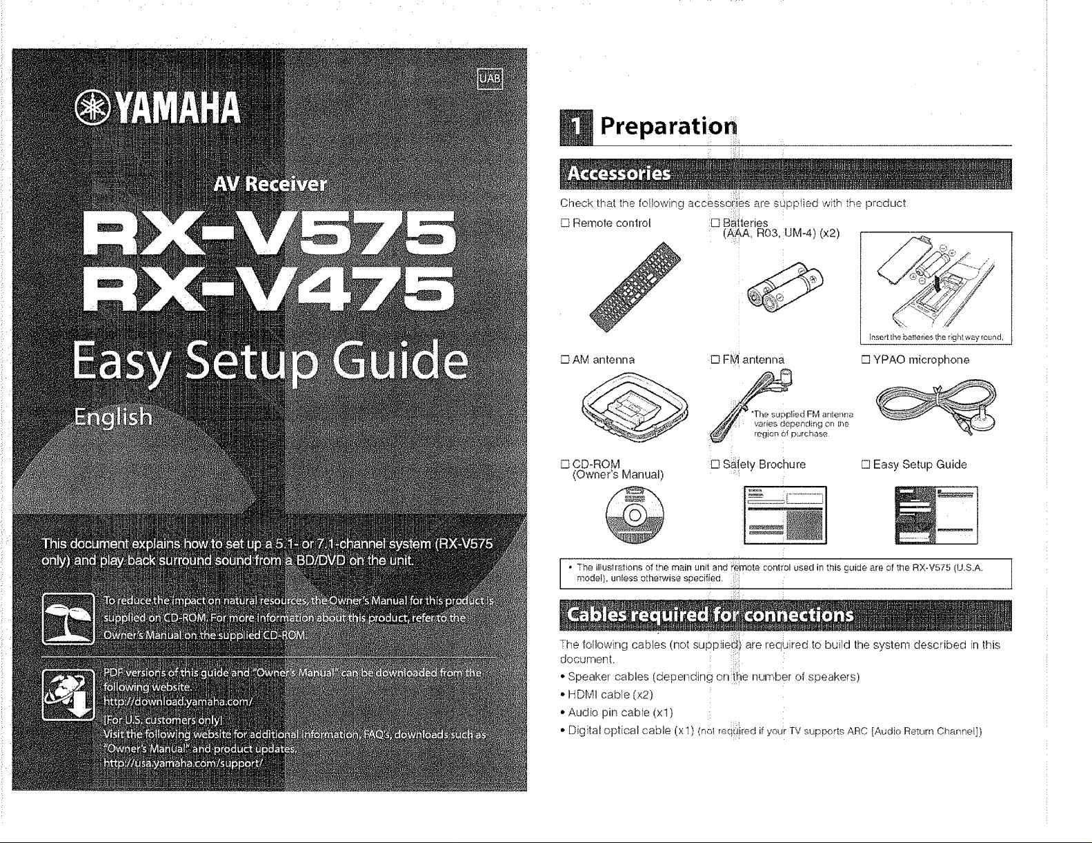
Check that the following accessdF!i_s are s_pptied with the product
,_ Rernote conlrol :[3 Baiteries
:: : i
=r
(A_A, R03, :UM-4)(x2)
0
Insert the batteries the rlgl'_tway round,
[] AM antenna
[] F_ Iantenna
Varies depending on _he
region Of purchase
[] YPAO rnicrophone
supplied FM antenna
D CD-ROM
(Owner's Manual)
:[3 S_(ely Brochure
: _L____j
[] Easy Setup Guide
@
• The ilfustrafionsof them_in un4tandt'e_'notecontrol usedin this guide are of'_heRX-V575 (U,S.A.
modef},unless otherwisespecilied.
The loIIowing cables (not supptie!i i are reqGred tObuild the system described it1this
document.
* Speaker cables (depending on :![il÷ number of speakers)
• HDMI cable (x2)
• Audio pin cable (xl)
• Digital optical cable (x l) (nol reqi_i=iredif your TV supports ARC [Audio Rettlrn Channel])
Page 2
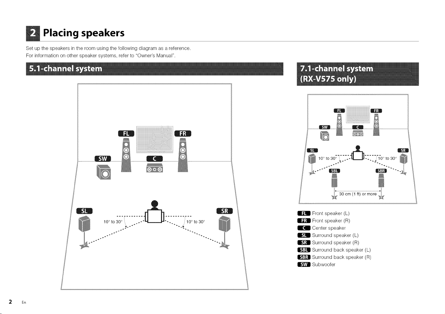
Placing speakers
Set up the speakers in the room using the following diagram as a reference.
For information on other speaker systems, refer to "Owner's Manual".
_i_iiiiiiiiiiiiiiiiiiiiiiiiiiiiiiiiiiiiiiiiiiiiiiiiiiiiiD
* 30cm(1 ft) or more ,,
2 En
_o:i....._:.{[_::_ "
10° to ..... . 10° to 30°
I_ Front speaker (L)
Front speaker (R)
Ii_ Center speaker
IL"!!I Surround speaker (L)
Surround speaker (R)
Surround back speaker (L)
Surround back speaker (R)
| Subwoofer
Page 3
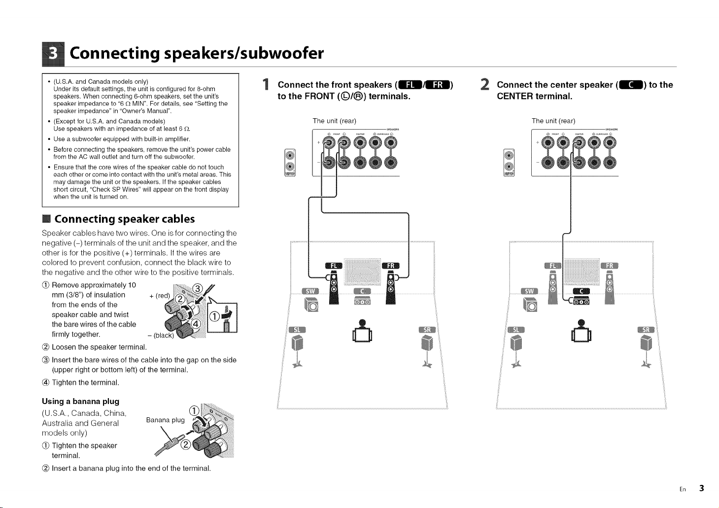
Connecting speakers/subwoofer
• (U.S.A. and Canada models only)
Under its default settings, the unit is configured for 8-ohm
speakers. When connecting 6-ohm speakers, set the unit's
speaker impedance to "6 £_ MIN". For details, see "Setting the
speaker impedance" in "Owner's Manual".
• (Except for U.S.A. and Canada models)
Use speakers with an impedance of at least 6 G.
• Use a subwoofer equipped with built-in amplifier.
• Before connecting the speakers, remove the unit's power cable
from the AC wall outlet and turn off the subwoofer.
• Ensure that the core wires of the speaker cable do not touch
each other or come into contact with the unit's metal areas. This
may damage the unit or the speakers. Ifthe speaker cables
short circuit, "Check SP Wires" will appear on the front display
when the unit is turned on.
[] Connecting speaker cables
Speaker cables have two wires. One is for connecting the
negative (-) terminals of the unit and the speaker, and the
other is for the positive (+) terminals. If the wires are
colored to prevent confusion, connect the black wire to
the negative and the other wire to the positive terminals.
(_) Remove approximately 10
mm (3/8") of insulation
from the ends of the
speaker cable and twist
the bare wires of the cable
firmly together.
(_) Loosen the speaker terminal.
(_) Insert the bare wires of the cable into the gap on the side
(upper right or bottom left) of the terminal.
(_) Tighten the terminal.
Connect the front speakers (Ir_ll/ll_]l)
to the FRONT (Q/®) terminals.
The unit (rear)
2 Connect the center speaker (IrdB) to the
CENTER terminal.
The unit (rear)
Using a banana plug
(U.S.A., Canada, China,
Australia and General
models only)
(_)Tighten the speaker
terminal.
(_) Insert a banana plug into the end of the terminal.
En 3
Page 4
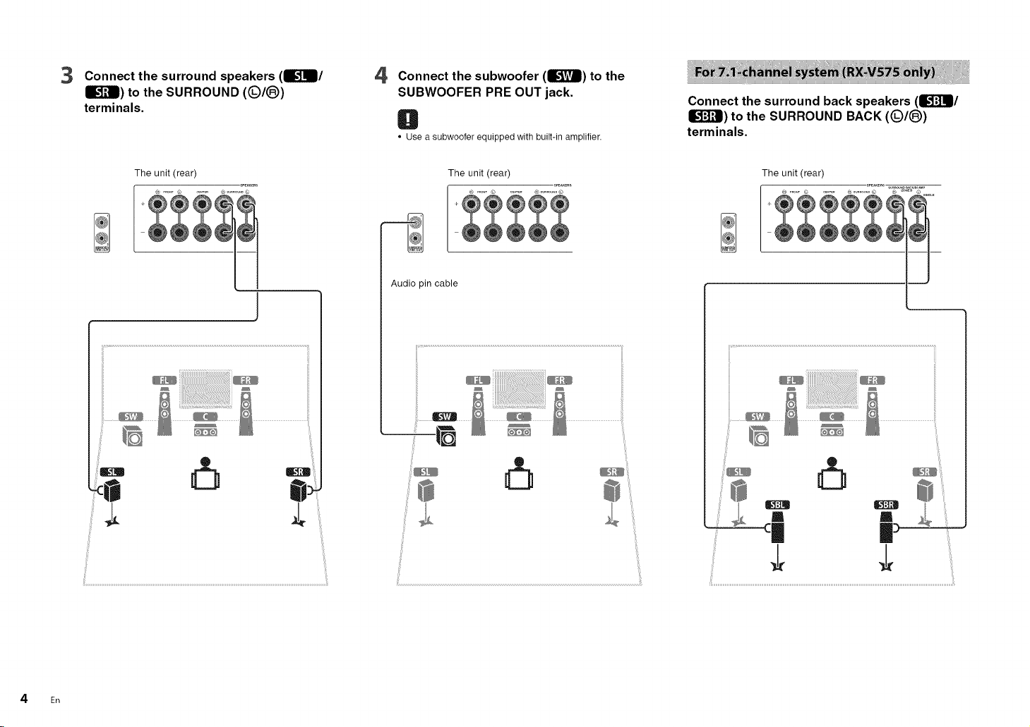
3 Connect the surround speakers (m3J]m/
m_J_l) to the SURROUND (Q/(_)
terminals.
4 Connect the subwoofer (L'_!Tm) to the
SUBWOOFER PRE OUT jack.
O
• Use a subwoofer equipped with built-in amplifier.
Connect the surround back speakers (13J'_Jl/
• _J_) to the SURROUND BACK (Q/(_)
terminals.
The unit (rear)
The unit (rear) The unit (rear)
Audio pin cable
I
_iiiiiiiiiiiiiiiiiii_i_!_i_i_i_i_i_i_i_i_ii_ii_ii_i_ii_i_i_ii_ii_ii_ii_ii_ii_ii_ii_ii_ii_ii_ii_ii_ii_i_!i_iii_®
ii_ __i!iii!iii!iiiiililii!iiiiiiiiii!ii!i
@'i_:iiii!
I"
4 En
Page 5
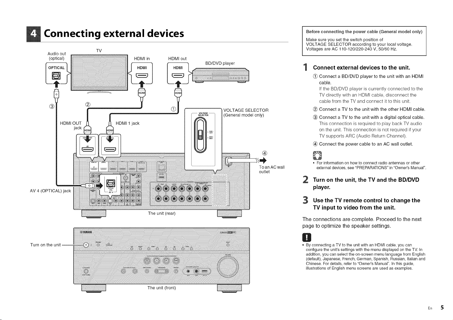
Connecting external devices
Audio out
(optical) HDMI in HDMI out
jack
AV 4 (OPTICAL) jack
TV
®
The unit (rear)
BD/DVD player
VOLTAGE SELECTOR
'General model only)
Before connecting the power cable (Genera_ mode_ on_y)
Make sure you set the switch position of
VOLTAGE SELECTOR according to your local voltage.
Voltages are AC 110-120/220-240 V, 50/60 Hz.
Connect external devices to the unit.
(_) Connect a BD/DVD player to the unit with an HDMI
cable.
If the BD/DVD player is currently connected to the
TV directly with an HDMI cable, disconnect the
cable from the TV and connect it to this unit.
(_) Connect a TV to the unit with the other HDMI cable.
(_) Connect a TV to the unit with a digital optical cable.
This connection is required to play back TV audio
on the unit. This connection is not required if your
TV supports ARC (Audio Return Channel).
(_) Connect the power cable to an AC wall outlet.
• Forinformation on how to connect radio antennas or other
external devices, see "PREPARATIONS" in "Owner's Manual".
2 Turnon the unit, the TV and the BD/DVD
player.
3 Use the TV remote control to change the
TV input to video from the unit.
The connections are complete. Proceed to the next
page to optimize the speaker settings.
Turn on the
The unit (front)
O
• By connecting a TV to the unit with an HDMI cable, you can
configure the unit's settings with the menu displayed on the TV. In
addition, you can select the on-screen menu language from English
(default), Japanese, French, German, Spanish, Russian, Italian and
Chinese. For details, refer to "Owner's Manual". In this guide,
illustrations of English menu screens are used as examples.
En 5
Page 6
B Optimizing the speaker settings automatically (YPAO)
The Yamaha Parametric room Acoustic Optimizer (YPAO) function detects speaker connections, measures the
distances from them to your listening position(s), and then automatically optimizes the speaker settings, such as
volume balance and acoustic parameters, to suit your room.
• During the measuring process, test tones are output at high volume. Ensure that
the test tones do not frighten small children. Also, refrain from using this function at
night when it may be a nuisance to others.
• During the measuring process, you cannot adjust the volume.
• During the measuring process, keep the room as quiet as possible.
• Do not connect headphones.
• Do not stand between the speakers and the YPAO microphone during the
measurement process (about 3 minutes).
• Move to the corner of the room or leave the room.
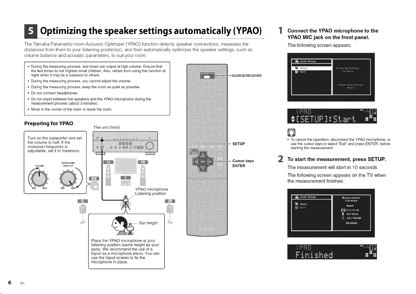
Connect the YPAO microphone to the
YPAO MIC jack on the front panel.
The following screen appears.
Preparing for YPAO
Turn on the subwoofer and set
the volume to half. If the
crossover frequency is
adjustable, set it to maximum.
6 En
CROSSOVER/
HIGH CUTVOLUME
The unit (front)
Ear height
Place the YPAO microphone at your
listening position (same height as your
ears). We recommend the use of a
tripod as a microphone stand. You can
use the tripod screws to fix the
microphone in place.
SETUP
Cursor keys
ENTER
• To cancel the operation, disconnect the YPAO microphone, or
use the cursor keys to select "Exit" and press ENTER, before
starting the measurement.
2
To start the measurement, press SETUP.
The measurement will start in 10 seconds.
The following screen appears on the TV when
the measurement finishes.
Page 7
O
• Ifthe cursor keys do not work, press SOURCE/RECEIVER (to
light up the key in orange) and then use the cursor keys.
• Ifany error message (such as E-1) or warning message (such
as W-2) appears, see "Error messages" or "Warning
messages" in "Owner's Manual".
• Ifthe warning message "W-1:Out of Phase" appears, see "If
"W-1:Out of Phase" appears".
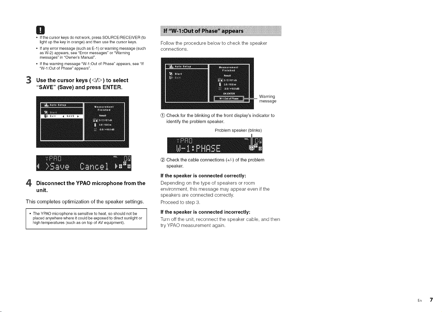
3
Use the cursor keys (_d/I>) to select
"SAVE" (Save) and press ENTER.
4 Disconnect the YPAO microphone from the
unit.
This completes optimization of the speaker settings.
• The YPAO microphone is sensitive to heat, so should not be
placed anywhere where it could be exposed to direct sunlight or
high temperatures (such as on top of AV equipment).
Follow the procedure below to check the speaker
connections.
__ Warning
message
(_) Check for the blinking of the front display's indicator to
identify the problem speaker.
Problem speaker (blinks)
(_) Check the cable connections (+/-) of the problem
speaker.
If the speaker is connected correctly:
Depending on the type of speakers or room
environment, this message may appear even if the
speakers are connected correctly.
Proceed to step 3.
If the speaker is connected incorrectly:
Turn off the unit, reconnect the speaker cable, and then
try YPAO measurement again.
En 7
Page 8
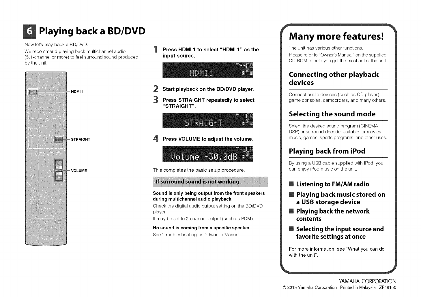
Playing back a BD/DVD
Now let's play back a BD/DVD.
We recommend playing back multichannel audio
(5.1-channel or more) to feel surround sound produced
by the unit.
HDMI 1
Press HDMI 1 to select "HDMI 1" as the
input source.
2 Start playback on the BD/DVD player.
3 Press STRAIGHT repeatedly to select
"STRAIGHT".
'4 Press VOLUME to adjust the volume.
This completes the basic setup procedure.
Sound is only being output from the front speakers
during multichannel audio playback
Check the digital audio output setting on the BD/DVD
player.
It may be set to 2-channel output (such as PCM).
No sound is coming from a specific speaker
See "Troubleshooting" in "Owner's Manual".
Many more features!
The unit has various other functions.
Please refer to "Owner's Manual" on the supplied
CD-ROM to help you get the most out of the unit.
Connecting other playback
devices
Connect audio devices (such as CD player),
game consoles, camcorders, and many others.
Selecting the sound mode
Select the desired sound program (CINEMA
DSP) or surround decoder suitable for movies,
music, games, sports programs, and other uses.
Playing back from iPod
By using a USB cable supplied with iPod, you
can enjoy iPod music on the unit.
B Listening to FM/AM radio
[] Playing back music stored on
a USB storage device
B Playing back the network
contents
B Selecting the input source and
favorite settings at once
For more information, see "What you can do
with the unit".
YAMAHA CORPORATION
© 2013 Yamaha Corporation Printed in Malaysia ZF49150
Page 9
@
AV Receiver
Owner's Manual
English
Read the supplied booklet "Safety Brochure" before using the unit.
Page 10
CONTENTS
Accessories ...................................................... 4
FEATURES 5
What you can do with the unit .................................... 5
Part names and functions ........................................ 7
Front panel ........................................................................................ 7
Front display (indicators) ........................................................................... 8
Rear panel ......................................................................................... g
Remote control ................................................................................... 10
PREPARATIONS 11
General setup procedure ........................................ 11
1 Placing speakers .............................................. 12
2 Connecting speakers .......................................... 15
5.1-channel system ............................................................................... 15
7.1-channel system ............................................................................... 15
Connecting front speakers that support bi-amp connections ....................................... 16
Connecting Zone B speakers ...................................................................... 16
Input/output jacks and cables ................................... 17
3 Connecting a TV ............................................... 18
4 Connecting playback devices .................................. 23
Connecting video devices (such as BD/DVD players) ............................................... 23
Connecting audio devices (such as CD players) ..................................................... 26
Connecting to the jacks on the front panel ......................................................... 26
5 Connecting the FM/AM antennas ............................... 27
6 Connecting to a network ....................................... 28
7 Connecting recording devices ................................. 29
8 Connecting the power cable ................................... 29
9 Selecting an on-screen menu language ......................... 30
10 Optimizing the speaker settings automatically (YPAO) ......... 31
Error messages .................................................................................... 33
Warning messages ................................................................................ 34
PLAYBACK 35
Basic playback procedure ....................................... 35
Selecting the input source and favorite settings with one touch
(SCENE) ........................................................ 36
Configuring scene assignments .................................................................... 36
Selecting the sound mode ....................................... 37
Enjoying sound field effects (CINEMA DSP) ......................................................... 38
Enjoying unprocessed playback ................................................................... 40
Enjoying pure high fidelity sound (direct playback) ................................................. 41
Enjoying compressed music with enhanced sound (Compressed Music Enhancer) ................... 42
Enjoying surround sound with headphones (SILENT CINEMA) ....................................... 42
Listening to FM/AM radio ....................................... 43
Setting the frequency steps ........................................................................ 43
Selecting a frequency for reception ................................................................ 43
Registering favorite radio stations (presets) ........................................................ 44
Radio Data System tuning ......................................................................... 46
Playing back iPod music ......................................... 47
Connecting an iPod ............................................................................... 47
Playback of iPod content .......................................................................... 48
Playing back music stored on a USB storage device ............... 51
Connecting a USB storage device .................................................................. 51
Playback of USB storage device contents ........................................................... 51
En 2
Page 11
Playingbackmusicstoredonmediaservers(PCs/NAS)............ 54
Media sharing setup .............................................................................. 54
Playback of PC music contents .................................................................... 54
Listening to Internet radio ....................................... 57
Playing back iTunes/iPod music via a network (AirPlay) ........... 59
Playback of iTunes/iPod music contents ........................................................... 59
Playing back music in multiple rooms (RX-V575 only) ............. 61
Preparing Zone B ................................................................................. 61
Viewing the current status ...................................... 63
Switching information on the front display ........................................................ 63
Configuring playback settings for different playback sources
(Option menu) .................................................. 64
Option menu items ............................................................................... 64
CONFIGURATIONS 68
Controlling external devices with the remote control ............. 85
Registering the remote control code for a TV ....................................................... 85
Registering the remote control codes for playback devices ......................................... 86
Resetting remote control codes .................................................................... 87
Updating the unit's firmware via the network .................... 88
APPENDIX 89
Frequently asked questions ..................................... 89
Troubleshooting ................................................ 90
Power, system and remote control ................................................................. 90
Audio ............................................................................................. 92
Video ............................................................................................. 94
FM/AM radio ...................................................................................... 94
USB and network .................................................................................. 95
Error indications on the front display ............................ 96
Configuring various functions (Setup menu) ...................... 68
Setup menu items ................................................................................ 69
Speaker ........................................................................................... 71
HDMI ............................................................................................. 74
Sound ............................................................................................ 75
ECO .............................................................................................. 77
Function .......................................................................................... 78
Network .......................................................................................... 80
Language ......................................................................................... 82
Configuring the system settings (ADVANCED SETUP menu) ........ 83
ADVANCED SETUP menu items .................................................................... 83
Changing the speaker impedance setting (SP IMP.) ................................................. 83
Selecting the remote control ID (REMOTE ID) ....................................................... 83
Changing the FM/AM tuning frequency setting (TU) ................................................ 84
Switching the video signal type (TV FORMAT) ...................................................... 84
Restoring the default settings (INIT) ................................................................ 84
Updating the firmware (UPDATE) .................................................................. 84
Checking the firmware version (VERSION) .......................................................... 84
Glossary ....................................................... 97
Audio information ................................................................................. 97
HDMI and video information ....................................................................... 98
Yamaha technologies ............................................................................. 99
Video signal flow ................................................................................. 100
Information on HDMI .......................................... 1OO
HDMI Control .................................................................................... 100
HDMI signal compatibility ........................................................................ 102
Reference diagram (rear panel) ................................. 103
Trademarks ................................................... 104
Specifications ................................................. 105
Index ......................................................... 108
E. 3
Page 12

Accessories
Check that the following accessories are supplied with the product.
Ope_athg _ar'}ge of the r_mete co_'_t_o_
• Point the remote control at the remote control sensor on the unit and remain within the operating range
shown below.
[] Remote control
[] AM antenna
[] Batteries (AAA, R03, UM-4) (x2)
[] FM antenna
iF
*One of the above is supplied depending on the region of
purchase.
[] YPAO microphone
[] Easy Setup Guide [] Safety Brochure
[] CD-ROM (Owner's Manual)
Insert the batteries the right
way round.
Within 6 m (20 ft)
• The illustrations of the main unit and remote control used in this manual are of the RX-V575 (U.S.A.
model), unless otherwise specified.
• Some features are not available in certain regions.
• Due to product improvements, specifications and appearance are subject to change without notice.
• This manual explains operations using the supplied remote control.
• This manual describes all the "iPod", "iPhone" and "iPad" as the "iPod". "iPod" refers to "iPod", "iPhone"
and "iPad", unless otherwise specified.
• _ indicates precautions for use of the unit and its feature limitations.
• _j:_ indicates supplementary explanations for better use.
Accessories En 4
Page 13
FEATURES
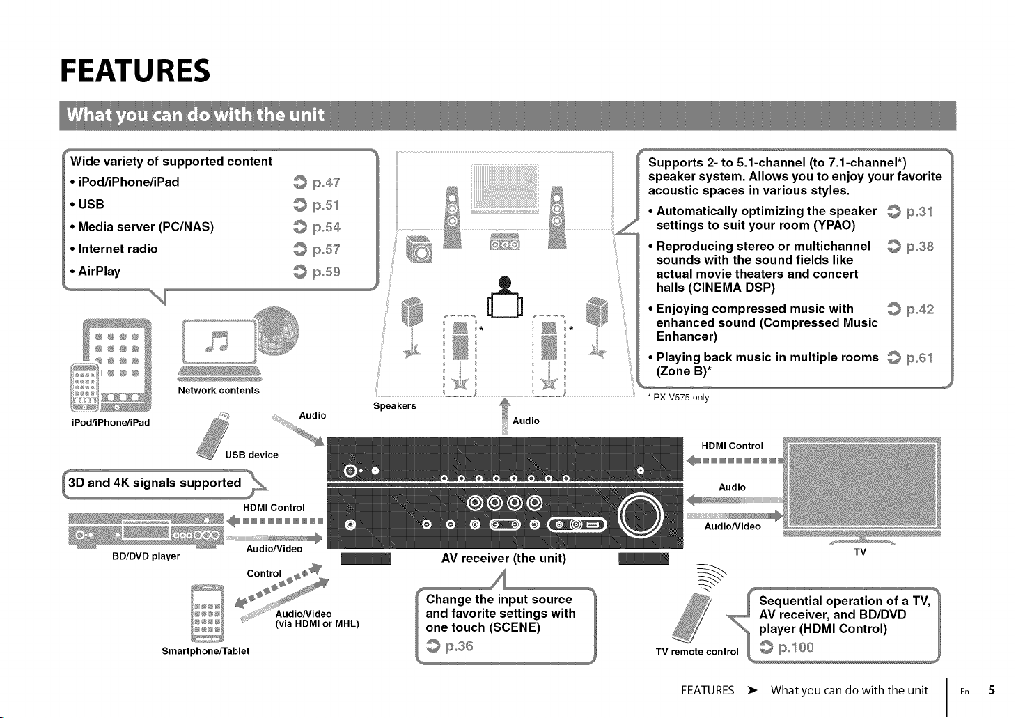
Wide variety of supported content
• iPod/iPhone/iPad
• USB
• Media server (PC/NAS)
• Internet radio
• AirPlay
Network contents
iPod/iPhone/iPad
HDMI Control
NNNNNNNNNN
_......... _........ Audio/V id eo
BD/DVD player
Control _
19o47
© ilSoSs
@ 19o54
@ 19o57
@ p,,59
Speakers
AV receiver (the unit)
Supports 2- to 5.1-channel (to 7.1-channel*)
speaker system. Allows you to enjoy your favorite
acoustic spaces in various styles.
• Automatically optimizing the speaker _ 11#o31
settings to suit your room (YPAO)
• Reproducing stereo or multichannel _ 11#38
sounds with the sound fields like
actual movie theaters and concert
• halls (CINEMA DSP)
Enjoying compressed music with _ 11#42
enhanced sound (Compressed Music
• Enhancer)
Playing back music in multiple rooms _ _3°61
(Zone B)*
....................................................................* RX-V575 only
HDMI Control
Audio
Audio/Video
TV
i;s
Smartphone/Tablet
Aud ON deo
.... (via NDMIorMHL)
and favorite settings with
one touch (SCENE)
© p.s6
_ Sequential operation of a TV_
AV receiver, and BD/DVD /
player (HDMI Control) /
remote_
TV control __
FEATURES • Whatyou can do with the unit En 5
Page 14

Full of useful functions! Useful tips
17 Connecting various devices (p.23)
A number of HDMI jacks and various input/output jacks
on the unit allow you to connect video devices (such as
BD/DVD players), audio devices (such as CD players),
game consoles, camcorders, and other devices.
17 Playing backTV audio in surround sound
with a single HDMI cable connection
(Audio Return Channel: ARC) (p.18)
When usinganARC-compatibleTV,youonlyneed one
HDMIcable toenablevideo output tothe TV,audio input
from theTV,andthetransmissionof HDMIControlsignals.
HDMI Control
TV audio
Video from
externaldevice
17 Easy operation and wireless music
playback from iPhone or Android device
By using the application for smartphone/tablet "AV
CONTROLLER", you can control the unit from an
iPhone, iPad, iPod touch or Android devices. Visit our
website for details.
17 Creating 3-dimensional sound fields (p.38)
The Virtual Presence Speaker (VPS) function allows you
to create a 3-dimensional sound field in your own room
(CINEMA DSP 3D).
17 Listening to FM/AM radio (p.43)
The unit is equipped with a built-in FM/AM tuner. You
can register up to 40 favorite radio stations as presets.
17 Enjoying pure high fidelity sound (p.41)
When the direct playback mode is enabled, the unit
plays back the selected source with the least circuitry,
which lets you to enjoy Hi-Fi sound quality.
17 Easy operation with a TV screen
You can operate the iPod or USB storage device, view
information, or easily configure the settings using the
on-screen menu.
17 Low power consumption
The ECO mode (power saving function) reduces the
unit's power consumption and helps to create an
eco-friendly home theater system (p.78).
The combination of video/audio input jacks does not
match an external device...
Use "Audio In" in the "Option" menu to change the
combination of video/audio input jacks so that it matches
the output jack(s) of your external device (p.25).
Video and audio are not synchronized...
Use "Lipsync" in the "Setup" menu to adjust the delay
between video and audio output (p.76).
I want to hear audio from the TV speakers...
Use "Audio Output" in the "Setup" menu to select the
output destination of signals input into the unit (p.74).
Your TV speakers may be selected as an output
destination.
I want to use the supplied remote control to operate
external devices...
Register the remote control codes of the external
devices (such as a TV and BD/DVD players) (p.85).
I want to change the on-screen menu language...
Use "Language" in the "Setup" menu to select a
language from English, Japanese, French, German,
Spanish, Russian, Italian and Chinese (p.30).
I want to update the firmware...
Use "Network Update" (p.88) in the "Setup" menu or
"UPDATE" (p.84) in the "ADVANCED SETUP" menu to
update the unit's firmware.
Many other settings are available that let you to
customize the unit. For details, see the following pages.
• SCENE settings (p.36)
• Sound/video settings and signal information for each
source (p.64)
• Various function settings (p.69)
• System settings (p.83)
FEATURES • Whatyou can do with the unit En 6
Page 15
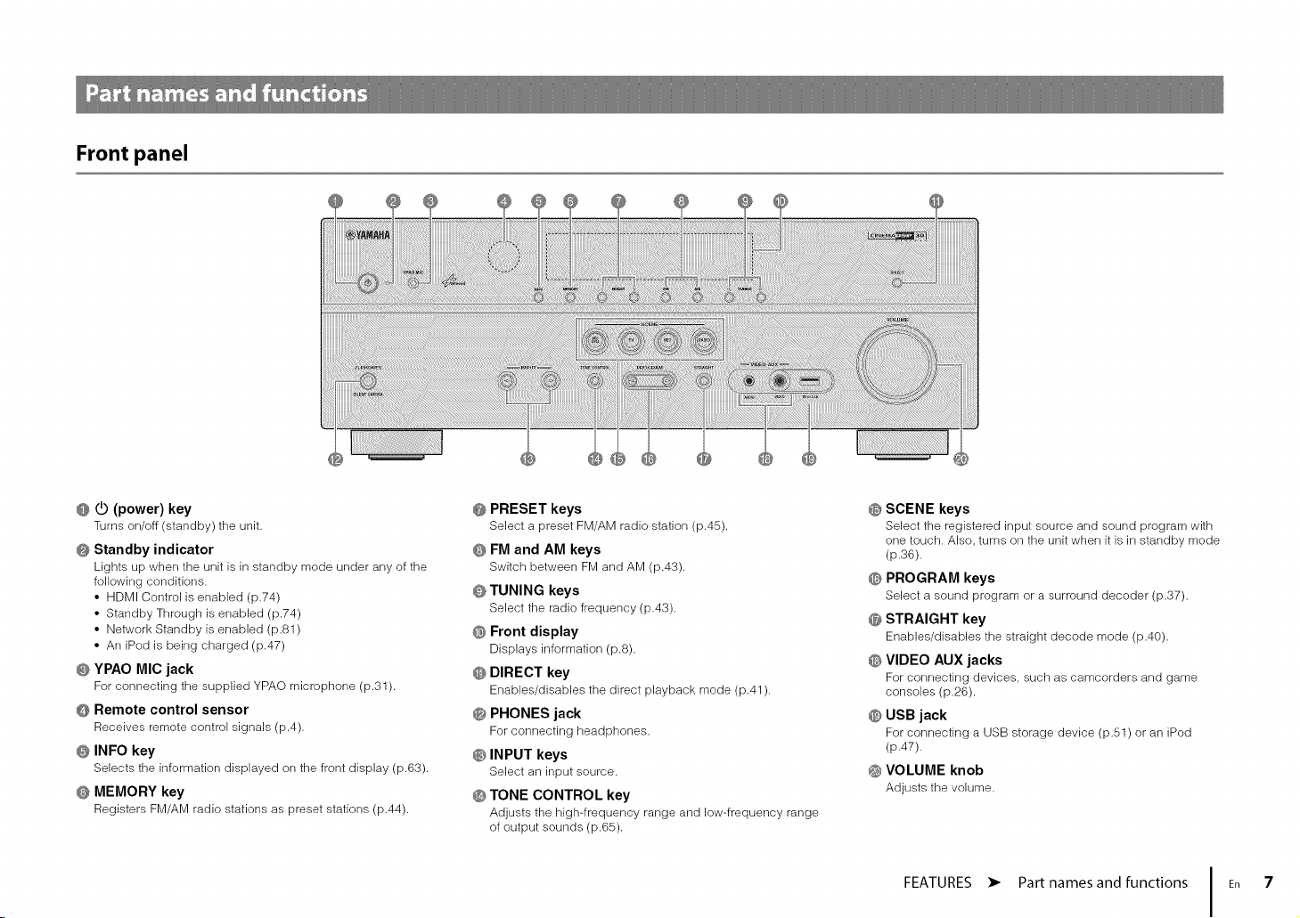
Front panel
@ @ (power) key
Turns on/off (standby) the unit.
@ Standby indicator
Lights up when tile unit is in standby mode under any of tile
following conditions.
• HDMI Control is enabled (19.74)
• Standby Through is enabled (19.74)
• Network Standby is enabled (19.81)
• An iPod is being charged (19.47)
@ YPAO MIC jack
For connecting the supplied YPAO microphone (19.31).
@ Remote control sensor
Receives remote control signals (19.4).
@ INFO key
Selects tile information displayed on tile front display (19.63).
@ MEMORY key
Registers FM/AM radio stations as preset stations (19.44).
@ PRESET keys
Select a preset FM/AM radio station (19.45).
@ FM and AM keys
Switch between FM and AM (19.43).
@ TUNING keys
Select tile radio frequency (19.43).
@ Front display
Displays information (p.8).
@ DIRECT key
Enables/disables the direct playback mode (19.41).
@ PHONES jack
For connecting headphones.
@ INPUT keys
Select an input source.
@ TONE CONTROL key
Adjusts the high-frequency range and low-frequency range
of output sounds (19.65).
@ SCENE keys
Select tile registered input source and sound program with
one touch. Also, turns on the unit when it is in standby mode
(p.36).
@ PROGRAM keys
Select a sound program or a surround decoder (19.37).
@ STRAIGHT key
Enables/disables the straight decode mode (19.40).
@ VIDEO AUX jacks
For connecting devices, such as camcorders and game
consoles (19.26).
@ USB jack
For connecting a USB storage device (19.51)or an iPod
(19.47).
@ VOLUME knob
Adjusts the volume.
FEATURES • Part names and functions En 7
Page 16

Front display (indicators)
@ HDMI
Lights up when HDMI signals are being input or output.
OUT
Lights up when HDMI signals are being output.
@ CINEMA DSP
Lights up when CINEMA DSP (p.38) is working.
CINEMA DSP "-_
Lights up when CINEMA DSP 3D (p.40) is working.
@ ENHANCER
Lights up when Compressed Music Enhancer (p.42) is
working.
@ ADAPTIVE DRC
Lights up when Adaptive DRC (p.65) is working.
@ STEREO
Lights up when the unit is receiving a stereo FM radio signal.
TUNED
Lights up when the unit is receiving an FM/AM radio station
signal.
@ ZONE indicators (RX-V575 only)
"SPA" lights up when the Zone A speaker output is enabled
and "SP B" lights up when the Zone B speaker output is
enabled (p.62).
@ SLEEP
Lights up when tile sleep timer is on.
@ MUTE
Blinks when audio is muted.
@ Volume indicator
Indicates tile current volume.
@ Cursor indicators
Indicate tile remote control cursor keys currently operational.
@ Information display
Displays tile current status (such as input name and sound
mode name). You can switch the information by pressing
INFO (p.63).
@ Speaker indicators
Indicate speaker terminals from which signals are output.
Subwoofer
Front speaker (L)
Front speaker (R)
Center speaker
Surround speaker (L)
Surround speaker (R)
Surround back speaker (L)*
Surround back speaker (R)*
Surround back speaker*
* RX-V575 only
FEATURES • Part names and functions En 8
Page 17
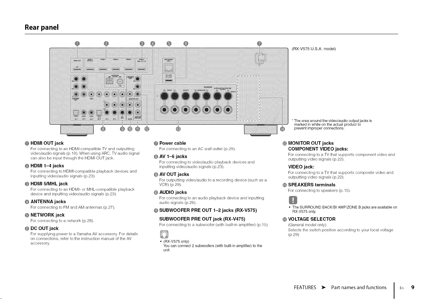
Rear panel
(RX-V575 U.S.A. model)
*The area around the video/audio output jacks is
marked in white on the actual product to
prevent improper connections.
@ HDMI OUT jack
For connecting to an HDMl-compatible TV and outputting
video/audio signals (p.18). When using ARC, TV audio signal
can also be input through the HDMI OUT jack.
@ HDMI 1-4 jacks
For connecting to HDMl-compatible playback devices and
inputting video/audio signals (p.23).
@ HDMI 5/MHL jack
For connecting to an HDMI- or MHL-compatible playback
device and inputting video/audio signals (p.23).
@ ANTENNA jacks
For connecting to FM and AM antennas (p.27).
@ NETWORK jack
For connecting to a network (p.28).
@ DO OUT jack
For supplying power to a Yamaha AV accessory. For details
on connections, refer to the instruction manual of the AV
accessory.
@ Power cable
For connecting to an AC wall outlet (p.29).
@ AV 1-6 jacks
For connecting to video/audio playback devices and
inputting video/audio signals (p.23).
@ AV OUT jacks
For outputting video/audio to a recording device (such as a
VCR) (p.29).
@ AUDIO jacks
For connecting to an audio playback device and inputting
audio signals (p.26).
@ SUBWOOFER PRE OUT 1-2 jacks (RX-V575)
SUBWOOFER PRE OUT jack (RX-V475)
For connecting to a subwoofer (with built-in amplifier) (p.15).
• (RX-V575 only)
You can connect 2 subwoofers (with built-in amplifier) to the
unit.
@ MONITOR OUT jacks
COMPONENT VIDEO jacks:
For connecting to a TV that supports component video and
outputting video signals (p.22).
VIDEO jack:
For connecting to a TV that supports composite video and
outputting video signals (p.22).
@ SPEAKERS terminals
For connecting to speakers (p.15).
• The SURROUND BACK/BI AMP/ZONE B jacks are available on
RX-V575 only.
@ VOLTAGE SELECTOR
(General model only)
Selects the switch position according to your local voltage
(p.29).
FEATURES • Part names and functions En 9
Page 18
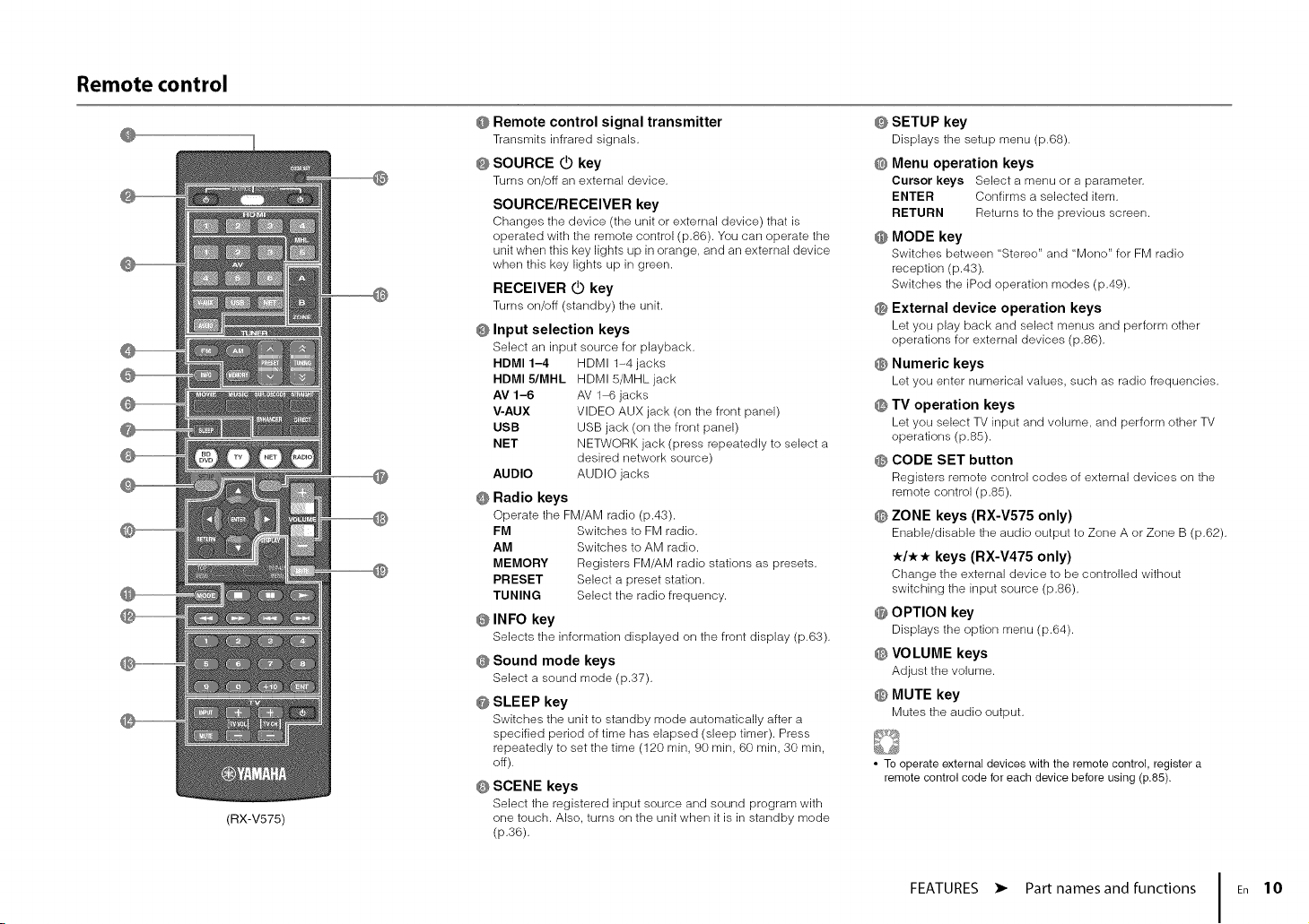
Remote control
@
(RX-V575)
@
@ Remote control signal transmitter
Transmits infrared signals.
@ SOURCE @ key
Turns on/off an external device.
SOURCE/RECEIVER key
Changes the device (the unit or external device) that is
operated with the remote control (p.86). You can operate the
unit when this key lights up in orange, and an external device
when this key lights up in green.
RECEIVER @ key
Turns on/off (standby) the unit.
@ Input selection keys
Select an input source for playback.
HDMI 1-4 HDMI 1-4 jacks
HDMIS/MHL HDMI5/MHLjack
AV 1-6 AV 1-6 jacks
V-AUX VIDEO AUX jack (on the front panel)
USB USB jack (on the front panel)
NET NETWORK jack (press repeatedly to select a
AUDIO AUDIO jacks
@ Radio keys
Operate the FM/AM radio (p.43).
FM Switches to FM radio.
AM Switches to AM radio.
MEMORY Registers FM/AM radio stations as presets.
PRESET Select a preset station.
TUNING Select the radio frequency.
@ INFO key
Selects the information displayed on the front display (p.63).
@ Sound mode keys
Select a sound mode (p.37).
@ SLEEP key
Switches the unit to standby mode automatically after a
specified period of time has elapsed (sleep timer). Press
repeatedly to set the time (120 rain, 90 rain, 60 rain, 30 rain,
off).
@ SCENE keys
Select the registered input source and sound program with
one touch. Also, turns on the unit when it is in standby mode
(p.36).
desired network source)
@ SETUP key
Displays tile setup menu (p.68).
@ Menu operation keys
Cursor keys Select a menu or a parameter.
ENTER Confirms a selected item.
RETURN Returns to the previous screen.
@ MODE key
Switches between "Stereo" and "Mono" for FM radio
reception (p.43).
Switches the iPod operation modes (p.49).
@ External device operation keys
Let you play back and select menus and perform other
operations for external devices (p.86).
@ Numeric keys
Let you enter numerical values, such as radio frequencies.
@ TV operation keys
Let you select TV input and volume, and perform other TV
operations (p.85).
@ CODE SET button
Registers remote control codes of external devices on the
remote control (p.85).
@ ZONE keys (RX-V575 only)
Enable/disable the audio output to Zone A or Zone B (p.62).
*/** keys (RX-V475 only)
Change the external device to be controlled without
switching the input source (p.86).
@ OPTION key
Displays the option menu (p.64).
@ VOLUME keys
Adjust the volume.
@ MUTE key
Mutes the audio output.
• To operate external devices with the remote control, register a
remote control code for each device before using (p.85).
FEATURES • Part names and functions En 10
Page 19
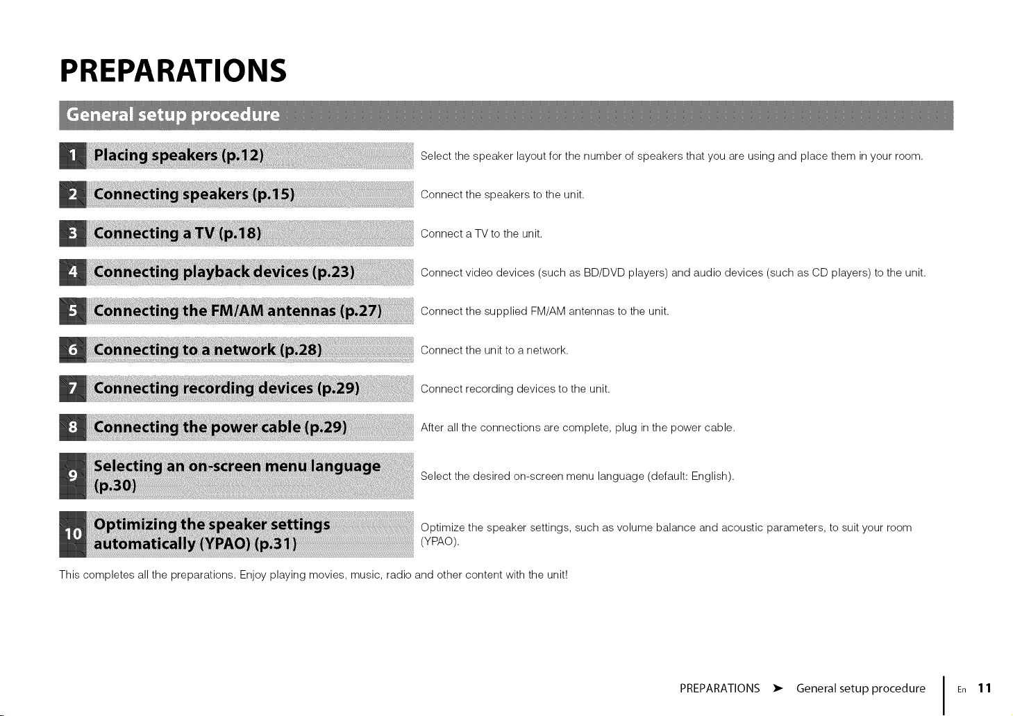
PREPARATIONS
Select the speaker layout for the number of speakers that you are using and place them in your room.
Connect the speakers to the unit.
Connect a TV to the unit.
Connect video devices (such as BD/DVD players) and audio devices (such as CD players) to the unit.
Connect the supplied FM/AM antennas to the unit.
Connect the unit to a network.
Connect recording devices to the unit.
After all the connections are complete, plug in the power cable.
Select the desired on-screen menu language (default: English).
Optimize the speaker settings, such as volume balance and acoustic parameters, to suit your room
(YPAO).
This completes all the preparations. Enjoy playing movies, music, radio and other content with the unit!
PREPARATIONS • General setup procedure En 11
Page 20
_Speakerplacement __@_
_,,_:_/¸_.®,. _' _ _,_
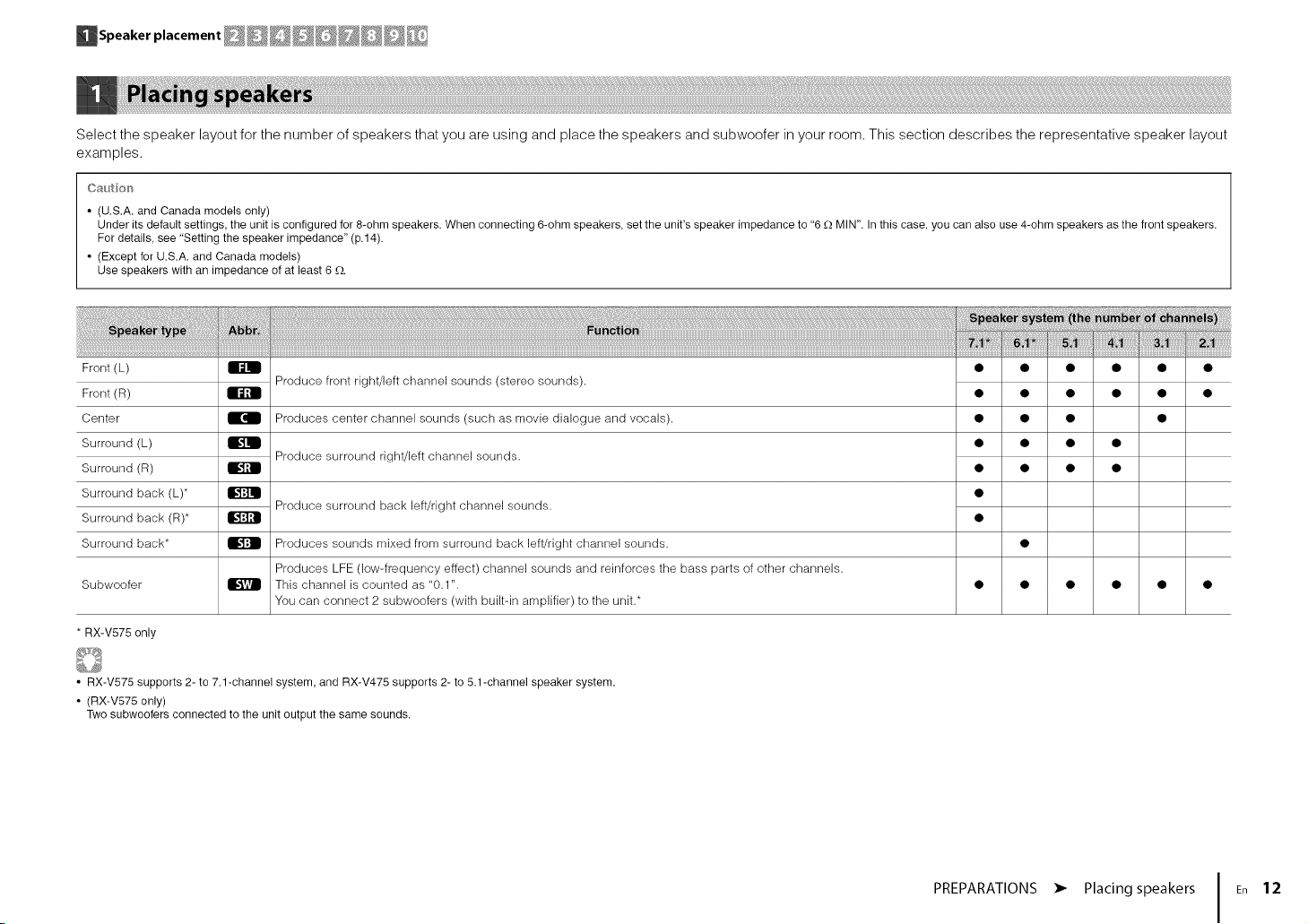
Select the speaker layout for the number of speakers that you are using and place the speakers and subwoofer in your room. This section describes the representative speaker layout
examples.
C_ution
• (U.S.A. and Canada models only)
Under its default settings, the unit is configured for 8-ohm speakers. When connecting 6-ohm speakers, set the unit's speaker impedance to "6 -Q MIN". In this case, you can also use 4-ohm speakers as the front speakers.
For details, see "Setting the speaker impedance" (p.14).
• (Except for U.S.A. and Canada models)
Use speakers with an impedance of at least 6 G.
Front (L) _ •
Front (R) _ •
Center _ Produces center channel sounds (such as movie dialogue and vocals). •
Surround (L) _ •
Surround (R) _ •
Surround back (L)* _ •
Surround back (R)* _ •
Surround back* _ Produces sounds mixed from surround back left/right channel sounds.
Subwoofer _ This channel is counted as "0.1". •
* RX-V575 only
• RX-V575 supports 2- to 7.1-channel system, and RX-V475 supports 2- to 5.1-channel speaker system.
• (RX-V575 only)
Two subwoofers connected to the unit output the same sounds.
Produce front right/left channel sounds (stereo sounds).
Produce surround right/left channel sounds.
Produce surround back left/right channel sounds.
Produces LFE (low-frequency effect) channel sounds and reinforces the bass parts of other channels.
You can connect 2 subwoofers (with built-in amplifier) to the unit.*
• •
• •
• •
• •
PREPARATIONS • Placing speakers En 12
Page 21
_Speaker placement __@_
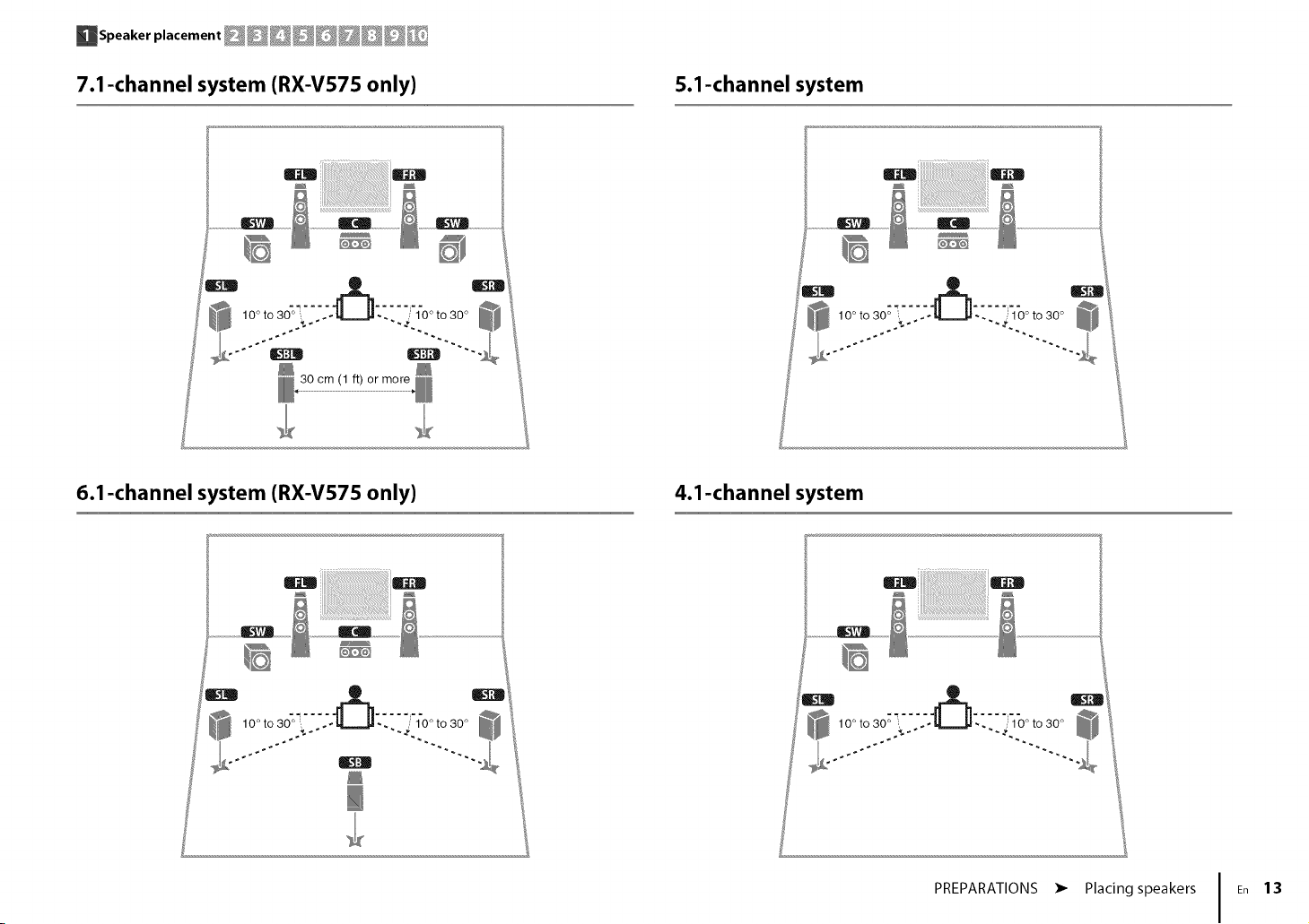
7.1-channel system (RX-V575 only)
i_ii_ii_i!iii!iiii!_ii_ii_i!_i!i!_iiii_i!i!_i_i_iiiii_ii!i!!i!!i!iii!i!i_i_i_ii_ii!i_i_i!i!_ii
6.1-channel system (RX-V575 only)
miiiiii !D
5.1-channel system
, 10° to 30°
4.1-channel system
uiiii
PREPARATIONS •
Placing speakers
13
Page 22
_Speaker placement __@_
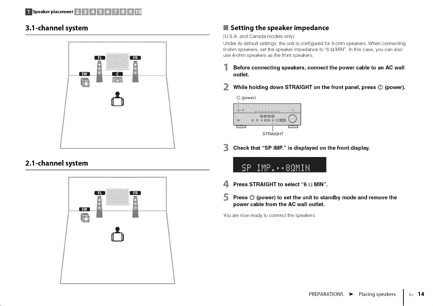
3.1-channel system
.....................o ......................iiiiiiiiiiiiiii iiiiiiiiiiiiii........
2.1-channel system
@ Setting the speaker impedance
(U.S.A.and Canada models only)
Under its default settings, the unit is configured for 8-ohm speakers. When connecting
6-ohm speakers, set the speaker impedance to "6 _-_MIN". In this case, you can also
miiiiiiiiiiiiiiiiiiiiiiiiii_!_ii_!i!i!i!i!i!i!i!i!i!i!i!ii!_i_iii_i_i_i_i_i_ii_ii_ii_i!_!_!!ii_iim
use4-ohm speakers as thefront speakers.
Before connecting speakers, connect the power cable to an AC wall
outlet.
2 While holding down STRAIGHT on the front panel, press _ (power).
d_ (power)
STRAIGHT
3
Check that "SP IMP." is displayed on the front display.
4 Press STRAIGHT to select "6 _ MIN".
5 Press _ (power) to set the unit to standby mode and remove the
power cable from the AC wall outlet.
You are now ready to connect the speakers.
PREPARATIONS • Placing speakers En 14
Page 23
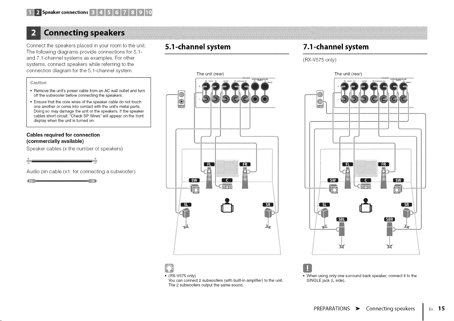
Connectthespeakersplacedinyourroomtotheunit.
Thefollowingdiagramsprovideconnectionsfor5.1-
and7.1-channelsystemsasexamples.Forother
systems,connectspeakerswhilereferringtothe
connectiondiagramforthe5.1-channelsystem.
Oautio_'_
• Remove the unit's power cable from an AC wall outlet and turn
off the subwoofer before connecting the speakers.
• Ensure that the core wires of the speaker cable do not touch
one another or come into contact with the unit's metal parts.
Doing so may damage the unit or the speakers. If the speaker
cables short circuit, "Check SP Wires" will appear on the front
display when the unit is turned on.
Cables required for connection
(commercially available)
Speaker cables (x the number of speakers)
Audio pin cable (xl: for connecting a subwoofer)
,_ _,_
S.l-channel system
The unit (rear)
@..... © ...... @........ ©
7.1-channel system
(RX-V575 only)
The unit (rear)
• (RX-V575 only)
You can connect 2 subwoofers (with built-in amplifier) to the unit.
The 2 subwoofers output the same sound.
• When using only one surround back speaker, connect it to the
SINGLE jack (L side).
PREPARATIONS • Connecting speakers En 1S
Page 24
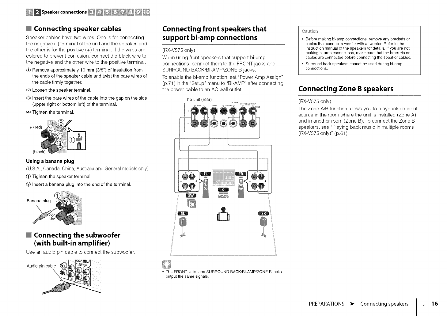
Connecting speaker cables
Speaker cables have two wires. One is for connecting
the negative (-) terminal of the unit and the speaker, and
the other is for the positive (+) terminal. If the wires are
colored to prevent confusion, connect the black wire to
the negative and the other wire to the positive terminal.
(_) Remove approximately 10 mm (3/8") of insulation from
the ends of the speaker cable and twist the bare wires of
the cable firmly together.
(_) Loosen the speaker terminal.
(_) Insert the bare wires of the cable into the gap on the side
(upper right or bottom left) of the terminal.
(_)Tighten the terminal.
red / F
+( J
Using a banana plug
(U.S.A., Canada, China, Australia and General models only)
(_)Tighten the speaker terminal.
(_) Insert a banana plug into the end of the terminal.
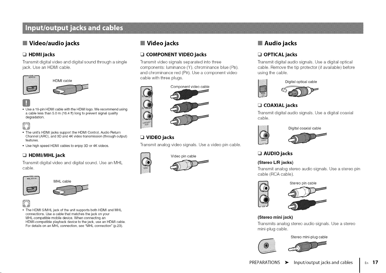
Connecting front speakers that
support bi-amp connections
(RX-V575 only)
When using front speakers that support bi-amp
connections, connect them to the FRONT jacks and
SURROUND BACK/BI-AMP/ZONE B jacks.
To enable the bi-amp function, set "Power Amp Assign"
(p.71) in the "Setup" menu to "BI-AMP" after connecting
the )ower cable to an AC wall outlet.
The unit (rear)
Caution
• Before making bi-amp connections, remove any brackets or
cables that connect a woofer with a tweeter. Refer to the
instruction manual of the speakers for details. If you are not
making bi-amp connections, make sure that the brackets or
cables are connected before connecting the speaker cables.
• Surround back speakers cannot be used during bi-amp
connections.
Connecting Zone B speakers
(RX-V575 only)
The Zone A/B function allows you to playback an input
source in the room where the unit is installed (Zone A)
and in another room (Zone B). To connect the Zone B
speakers, see "Playing back music in multiple rooms
(RX-V575 only)" (p.61).
Connecting the subwoofer
(with built-in amplifier)
Use an audio pin cable to connect the subwoofer.
Audio pincable _,_
• The FRONT jacks and SURROUND BACK/BI-AMP/ZONE B jacks
output the same signals.
PREPARATIONS • Connecting speakers En 16
Page 25
Video/audio jacks
Video jacks
Audio jacks
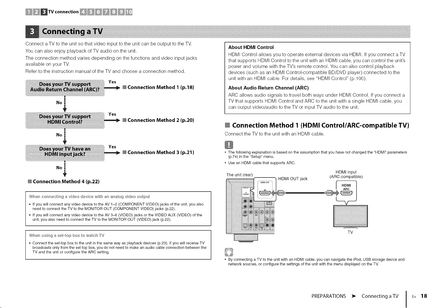
17 HDMI jacks
Transmit digital video and digital sound through a single
jack. Use an HDMI cable.
HDMI cable
• Use a 19-pin HDMI cable with the HDMI logo. We recommend using
a cable less than 5.0 m (16.4 ft) long to prevent signal quality
degradation.
• The unit's HDMI jacks support the HDMI Control, Audio Return
Channel (ARC), and 3D and 4K video transmission (through output)
features.
• Use high speed HDMI cables to enjoy 3D or 4K videos.
17 HDMI/MHL jack
Transmit digital video and digital sound. Use an MHL
cable.
MHL cable
17 COMPONENT VIDEO jacks
Transmit video signals separated into three
components: luminance (Y), chrominance blue (PB),
and chrominance red (PR). Use a component video
cable with three plugs.
Component video cable
17 VIDEO jacks
Transmit analog video signals. Use a video pin cable.
Video pin cable
17 OPTICAL jacks
Transmit digital audio signals. Use a digital optical
cable. Remove the tip protector (if available) before
using the cable.
Digital optical cable
_1 COAXIAL jacks
Transmit digital audio signals. Use a digital coaxial
cable.
Digital coaxial cable
17 AUDIO jacks
(Stereo L/R jacks)
Transmit analog stereo audio signals. Use a stereo pin
cable (RCA cable).
h_ Stereo pincable
• The HDMI 5/MHL jack of the unit supports both HDMI and MHL
connections. Use a cable that matches the jack on your
MHL-compatible mobile device. When connecting an
HDMI-compatible playback device to the jack, use an HDMI cable.
For details on an MHL connection, see "MHL connection" (p.23).
(Stereo mini jack)
Transmits analog stereo audio signals. Use a stereo
mini-plug cable.
Stereo mini-plugcable
PREPARATIONS • Input/output jacks and cables En 17
Page 26
ConnectaTVtotheunitsothatvideoinputtotheunitcanbeoutputtotheTV.
YoucanalsoenjoyplaybackofTVaudioontheunit.
Theconnectionmethodvariesdependingonthefunctionsandvideoinputjacks
availableonyourTV.
RefertotheinstructionmanualoftheTVandchooseaconnectionmethod.
Yes
@ Connection Method 1 (p.18)
==
No _,
==
Yes
@ Connection Method 2 (p.20)
==
No =_
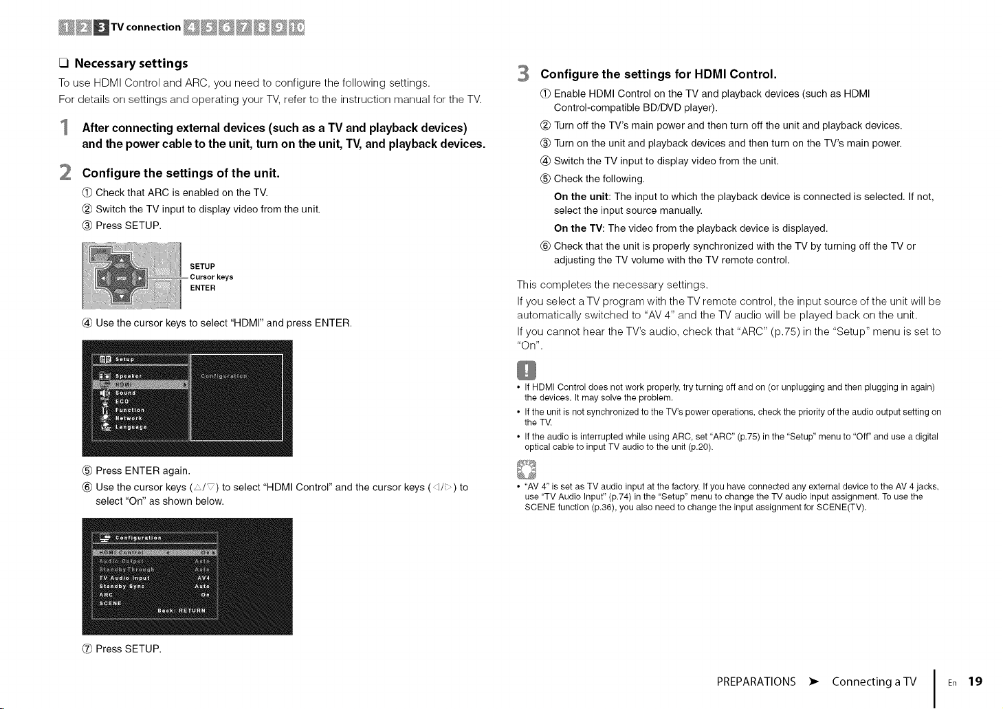
About HDMI Control
HDMI Control allows you to operate external devices via HDMI. If you connect a TV
that supports HDMI Control to the unit with an HDMI cable, you can control the unit's
power and volume with the TV's remote control. You can also control playback
devices (such as an HDMI Control-compatible BD/DVD player) connected to the
unit with an HDMI cable. For details, see "HDMI Control" (p.100).
About Audio Return Channel (ARC)
ARC allows audio signals to travel both ways under HDMI Control. If you connect a
TV that supports HDMI Control and ARC to the unit with a single HDMI cable, you
can output video/audio to the TV or input TV audio to the unit.
Connection Method 1 (HDMI Control/ARC-compatible TV)
Connect the TV to the unit with an HDMI cable.
Connection Method 3 (p.21)
==
No ==
==
T
@ Connection Method 4 (p.22)
Whe_'_eo_'_"_ecthg a video device with a_"_a_"_a_ogvideo outpost
• If you will connect any video device to the AV 1-2 (COMPONENT VIDEO) jacks of the unit, you also
need to connect the TV to the MONITOR OUT (COMPONENT VIDEO) jacks (p.22).
• If you will connect any video device to the AV 3-6 (VIDEO) jacks or the VIDEO AUX (VIDEO) of the
unit, you also need to connect the TV to the MONITOR OUT (VIDEO) jack (p.22).
Whe_"_ ushg a set-top box to watch TV
• Connect the set-top box to the unit in the same way as playback devices (p.23). If you will receive TV
broadcasts only from the set-top box, you do not need to make an audio cable connection between the
TV and the unit or configure the ARC setting.
• The following explanation is based on the assumption that you have not changed the "HDMI" parameters
(p.74) in the "Setup" menu.
• Use an HDMI cable that supports ARC.
The unit (rear) (ARC-compatible)
HDMI OUT jack
HDMI input
TV
• By connecting a TV to the unit with an HDMI cable, you can navigate the iPod, USB storage device and
network sources, or configure the settings of the unit with the menu displayed on the TV.
PREPARATIONS • Connecting a TV En 18
Page 27
_]Necessary settings
To use HDMI Control and ARC, you need to configure the following settings.
For details on settings and operating your TV, refer to the instruction manual for the TV.
After connecting external devices (such as a TV and playback devices)
and the power cable to the unit, turn on the unit, TV, and playback devices.
Configure the settings of the unit.
(_)Check that ARC is enabled on the TV.
(_)Switch the TV input to display video from the unit.
(_) Press SETUP.
SETUP
ENTER
@ Use the cursor keys to select "HDMr' and press ENTER.
(_) Press ENTER again.
_) Use the cursor keys ( / ) to select "HDMI Control" and the cursor keys (<l/b) to
select "On" as shown below.
3 Configure the settings for HDMI Control.
(_) Enable HDMI Control on the TV and playback devices (such as HDMI
Control-compatible BD/DVD player).
(_) Turn off the TV's main power and then turn off the unit and playback devices.
(_) Turn on the unit and playback devices and then turn on the TV's main power.
@ Switch the TV input to display video from the unit.
(_) Check the following.
On the unit: The input to which the playback device is connected is selected. If not,
select the input source manually.
On the TV: The video from the playback device is displayed.
_) Check that the unit is properly synchronized with the TV by turning off the TV or
adjusting the TV volume with the TV remote control.
This completes the necessary settings.
If you select a TV program with the TV remote control, the input source of the unit will be
automatically switched to "AV 4" and the TV audio will be played back on the unit.
If you cannot hear the TV's audio, check that "ARC" (p.75) in the "Setup" menu is set to
"On".
• If HDMI Control does not work properly, try turning off and on (or unplugging and then plugging inagain)
the devices. It may solve the problem.
• If the unit is not synchronized to the TV's power operations, check the priority of the audio output setting on
the TV.
If the audio is interrupted while using ARC, set "ARC" (p.75) in the "Setup" menu to "Off" and use a digital
optical cable to input TV audio to the unit (p.20).
• "AV 4" is set as TV audio input at the factory. If you have connected any external device to the AV4 jacks,
use "TV Audio Input" (p.74) in the "Setup" menu to change the TV audio input assignment. To usethe
SCENE function (p.36), you also need to change the input assignment for SCENE(TV).
(_) Press SETUP.
PREPARATIONS • Connecting a TV En 19
Page 28
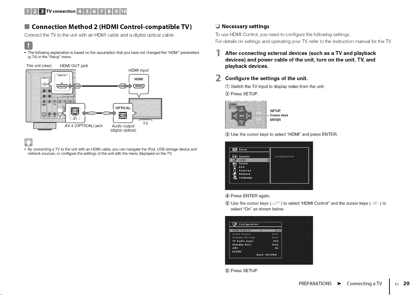
Connection Method 2 (HDMI Control-compatible TV)
Connect the TV to the unit with an HDMI cable and a digital optical cable.
_] Necessary settings
To use HDMI Control, you need to configure the following settings.
For details on settings and operating your TV, refer to the instruction manual for the TV.
• The following explanation is based on the assumption that you have not changed the "HDMI" parameters
(p.74) in the "Setup" menu.
The unit (rear) HDMI OUT jack
(digital optical)
• By connecting a TV to the unit with an HDMI cable, you can navigate the iPod, USB storage device and
network sources, or configure the settings of the unit with the menu displayed on the TV.
HDMI input
After connecting external devices (such as a TV and playback
devices) and power cable of the unit, turn on the unit, TV, and
playback devices.
2
Configure the settings of the unit.
(_)Switch the TV input to display video from the unit.
(_) Press SETUP.
SETUP
ENTER
(_) Use the cursor keys to select "HDMI" and press ENTER.
@ Press ENTER again.
(_) Use the cursor keys ( / ) to select "HDMI Control" and the cursor keys ( i/i: ) to
select "On" as shown below.
(_) Press SETUP.
PREPARATIONS • Connecting a TV En 20
Page 29
Configure the settings for HDMI Control.
(_) Enable HDMI Control on the TV and playback devices (such as a HDMI
Control-compatible BD/DVD player).
(_ Turn off the TV's main power and then turn off the unit and playback devices.
(_ Turn on the unit and playback devices and then turn on the TV.
@ Switch the TV input to display video from the unit.
(_) Check the following.
On the unit: The input to which the playback device is connected is selected. If not,
select the input source manually.
On the TV: The video from the playback device is displayed.
_) Check that the unit is properly synchronized with the TV by turning off the TV or
adjusting the TV volume with the TV remote control.
This completes the necessary settings.
If you select a TV program with the TV remote control, the input source of the unit will be
automatically switched to "AV 4" and the TV audio will be played back on the unit.
• If HDMI Control does not work properly, try turning off and on (or unplugging and then plugging in again)
the devices. It may solve the problem.
• If the unit is not synchronized to the TV's power operations, check the priority of the audio output setting on
the TV.
• "AV 4" is set as TV audio input at the factory. Ifyou have connected any external device to the AV 4 jacks or
if you want to use another input jack (other than OPTICAL) for connecting the TV, use "TV Audio Input"
(p.74) in the "Setup" menu to change the TV audio input assignment. To use the SCENE function (p.36),
you also need to change the input assignment for SCENE(TV).
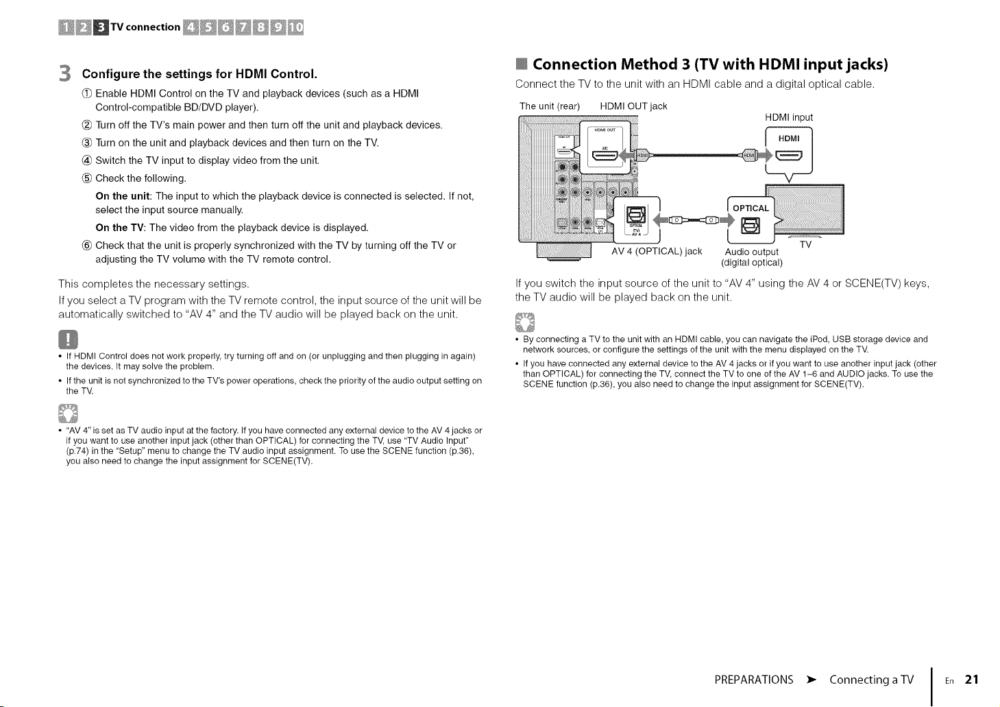
Connection Method 3 (TV with HDMI input jacks)
Connect the TV to the unit with an HDMI cable and a digital optical cable.
The unit (rear) HDMI OUT jack
AV 4 (OPTICAL) jack Audio output
(digital optical)
If you switch the input source of the unit to "AV 4" using the AV 4 or SCENE(TV) keys,
the TV audio will be played back on the unit.
• By connecting a TV to the unit with an HDMI cable, you can navigate the iPod, USB storage device and
network sources, or configure the settings of the unit with the menu displayed on the TV.
• If you have connected any external device to the AV 4 jacks or if you want to use another input jack (other
than OPTICAL) for connecting the TV, connect the TV to one of the AV 1-6 and AUDIO jacks. To use the
SCENE function (p.36), you also need to change the input assignment for SCENE(TV).
HDMI input
TV
PREPARATIONS • Connecting a TV En 21
Page 30
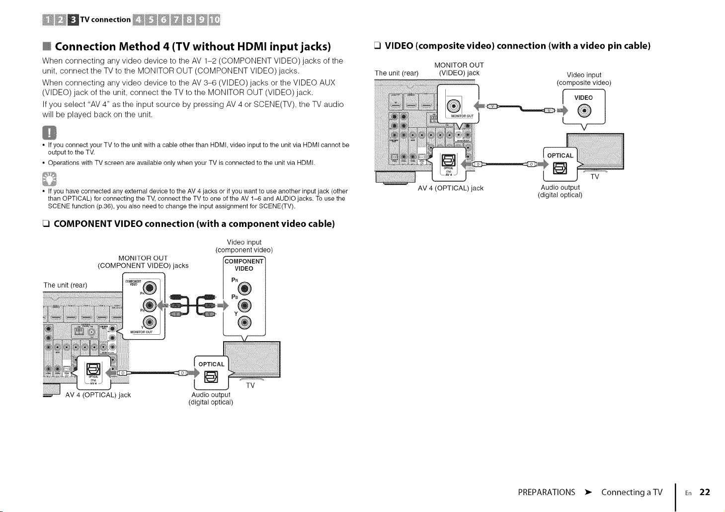
Connection Method 4 (TV without HDMI input jacks)
When connecting any video device to the AV 1-2 (COMPONENT VIDEO) jacks of the
unit, connect the TV to the MONITOR OUT (COMPONENT VIDEO) jacks.
When connecting any video device to the AV 3-6 (VIDEO) jacks or the VIDEO AUX
(VIDEO) jack of the unit, connect the TV to the MONITOR OUT (VIDEO) jack.
If you select "AV 4" as the input source by pressing AV 4 or SCENE(TV), the TV audio
will be played back on the unit.
• If you connect your TV to the unit with a cable other than HDMI, video input to the unit via HDMI cannot be
output to the TV.
• Operations with TV screen are available only when your TV is connected to the unit via HDMI.
FI VIDEO (composite video) connection (with a video pin cable)
The unit (rear) (VIDEO) jack
MONITOR OUT
Video input
(compositevideo)
v
• If you have connected any external device to the AV 4 jacks or if you want to use another input jack (other
than OPTICAL) for connecting the TV, connect the TV to one of the AV 1-6 and AUDIO jacks. To use the
SCENE function (p.36), you also need to change the input assignment for SCENE(TV).
_] COMPONENT VIDEO connection (with a component video cable)
Video input
MONITOR OUT
(COMPONENT VIDEO)jacks
(component video)
Audio output
(digital optical)
rCOMPONENT
VIDEO
AV 4 (OPTICAL)jack Audio output
(digital optical)
PREPARATIONS • Connecting a TV En 22
Page 31

_D Playloackdevice connections __
The unit is equipped with a variety of input jacks including HDMI input jacks to allow
you to connect different types of playback devices. For information on how to connect
an iPod or a USB storage device, see the following pages.
- Connecting an iPod (p.47)
- Connecting a USB storage device (p.51)
Connecting video devices (such as BD/DVD players)
Connect video devices such as BD/DVD players, set-top boxes (STBs) and game
consoles to the unit. Depending on the video/audio output jacks available on your video
device, choose one of the following connections. We recommend using an HDMI
connection if the video device has an HDMI output jack.
• If the combination of video/audio input jacks available on the unit does not match your video device, change
its combination according to the output jacks of your device (p.25).
HDMI connection
Connect a video device to the unit with an HDMI cable.
HDMI 1-5 jacks
The unit (rear) [__I_i_i_ /
If you select the input source by pressing HDMI 1-5, the video/audio played back on
the video device will be output from the unit.
_1 MHL connection
Connect an MHL-compatible mobile device (such as smartphones) to the unit with an
MHL cable. You can enjoy full HD videos and multichannel audio sources stored on the
mobile device. The HDMI 5 jack of the unit enables you to input videos and audio
directly from the mobile device to the unit.
The unit (rear)
If you select the input source by pressing HDMI 5, the video/audio played back on the
mobile device will be output from the unit.
• To watch videos input to the HDMI 5/MHL jack, you need to connect your TV to the HDMI OUT jack of the
unit (p.18 to 21).
• You need to prepare an MHL cable that match the jack on your mobile device.
• You can operate the mobile device using the menu operation keys, external device operation keys and
numeric keys on the remote control. However, some features may not be compatible, depending on the
mobile device or its application. In this case, operate the mobile device itself.
• If "Standby Through" (p.74) in the "Setup" menu is set to "On", you can output mobile device videos/audio
to the TV or operate the mobile device using the remote control of the unit even when the unit is in standby
mode.
• The unit supplies power to the mobile device in the following conditions.
- The unit is turned on.
- The unit is in standby mode while "Standby Through" (p.74) in the "Setup" menu is set to "On".
HDMI 5/MHL jack
MHL output
Mobile device
• Towatch videos input to the HDMI 1-5 jacks, you need to connect your TV to the HDMI OUT jack of the
unit (p.18 to 21).
PREPARATIONS • Connecting playback devices En 23
Page 32

@@DDp.oyboc.dov,co onno ..ons@D@D@%o.
Component video connection
Connect a video device to the unit with a component video cable and an audio cable
(digital optical or digital coaxial). Choose a set of input jacks (on the unit) depending on
the audio output jacks available on your video device.
Component video
AV 1-2
(COMPONENT VIDEO)
jacks
The
AV 2 (COAXIAL) jack Audio output
If you select the input source by pressing AV 1-2, the video/audio played back on the
video device will be output from the unit.
• Towatch videos input to the AV 1-2 (COMPONENT VIDEO) jacks, you need to connect your TV to the
MONITOR OUT (COMPONENT VIDEO) jacks of the unit (p.22).
Digital optical AV 1 (COMPONENT VIDEO + OPTICAL)
Digital coaxial AV 2 (COMPONENT VIDEO + COAXIAL)
Video output
(component video)
VIDEO
(digital optical or digital coaxial)
Composite video connection
Connect a video device to the unit with a video pin cable and an audio cable (digital
coaxial, digital optical, or stereo pin cable). Choose a set of input jacks (on the unit)
depending on the audio output jacks available on your video device.
Digital coaxial
Composite video
AV 3-6 (VIDEO) jack
The unit (rear)
Any of AV 3 (COAXIAL) jack, Audio output
AV 4 (OPTICAL) jack, (either digital optical,
AV 5-6 (AUDIO) jacks digital coaxial, or analog stereo)
Digital optical
Analog stereo
If you select the input source by pressing AV 3-6, the video/audio played back on the
video device will be output from the unit.
AV 3 (VIDEO + COAXIAL)
AV 4 (VIDEO + OPTICAL)
AV 5-6 (VIDEO + AUDIO)
Video output
(composite video)
I v,o o1
Video device
• To watch videos input to the AV 3-6 (VIDEO) jacks, you need to connect your TV to the MONITOR OUT
(VIDEO) jack of the unit (p.22).
PREPARATIONS • Connecting playback devices En 24
Page 33

@@@DP oyboc"device onno '°n'@D@D@%
Changing the combination of video/audio input jacks
If the combination of video/audio input jacks available on the unit does not match your
video device, change its combination according to the output jacks of your device. You
can connect a video device that has the following video/audio output jacks.
Digital optical HDMI 1-5
HDMI Digital coaxial HDMI 1-5 AV 2-3 (COAXIAL)
Analog stereo HDMI 1-5
Component video Analog stereo (COMPONENT AUDIO
AV 1-2 AV 5-6 (AUDIO)
VIDEO)
17 Necessary setting
For example, if you have connected a video device to AV 2 (COMPONENT VIDEO) and
AV 5 (AUDIO) jacks of the unit, change the combination setting as follows.
Video output
AV 2 (COMPONENT VIDEO) jacks
(component video)
COMPONENT
AV 1 (OPTICAL)
AV 4 (OPTICAL)
AV 5-6 (AUDIO)
AUDIO
VIDEO
After connecting external devices (such as a TV and playback
devices) and power cable of the unit, turn on the unit.
2
Press AV 2 to select "AV 2" (video input jack to be used) as the input
source.
AV 2
OPTION
ENTER
Press OPTION.
Use the cursor keys (A/V) to select "Audio In" and press ENTER.
Use the cursor keys (q/b) to select "AV 5" (audio input jack to be
used).
AV5 (AUDIO)jacks
Audio output
(analog stereo)
Press OPTION.
This completes the necessary settings.
If you select "AV 2" as the input source by pressing AV 2, the video/audio played back
on the video device will be output from the unit.
PREPARATIONS • Connecting playback devices En 25
Page 34

Connecting audio devices (such as CD players)
Connecting to the jacks on the front panel
Connect audio devices such as CD players and MD players to the unit. Depending on
the audio output jacks available on your audio device, choose one of the following
connections.
Digital optical AV 4 (OPTICAL)
Digital coaxial AV 2-3 (COAXIAL)
Analog stereo AUDIO
AV 1 (OPTICAL)
AV 5-6 (AUDIO)
The unit (rear)
AV 1-6 jacks
AUDIO jacks
Audio output
(eitherdigital optical,
digital coaxial, or analog stereo)
If you select the input source by pressing AV 1-6 or AUDIO, the audio played back on
the audio device will be output from the unit.
Use the VIDEO AUX jacks on the front panel to temporarily connect devices such as
camcorders and portable audio players to the unit.
Before making a connection, stop playback on the device and turn down the volume on
the unit.
The unit (front)
Portable audio player
Camcorder
If you select "V-AUX" as the input source by pressing V-AUX, the video/audio played
back on the device will be output from the unit.
• Towatch videos input to the VIDEO AUX (VIDEO) jack, you need to connect your TV to the MONITOR OUT
(VIDEO) jack of the unit (p.22).
• You need to prepare the video/audio cables that match the output jacks on your device.
• For details on how to connect an iPod or a USB storage device, see "Connecting an iPod" (p.47) or
"Connecting a USB storage device" (p.51).
• When "USB" is selected as the input source, video signals input to the VIDEO AUX (VIDEO) jack are output
from the MONITOR OUT (VIDEO) jack.
PREPARATIONS • Connecting playback devices En 26
Page 35

Connect the supplied FM/AM antennas to the unit.
Fix the end of the FM antenna to a wall, and place the AM antenna on a flat surface.
AM antenna
The unit (rear) _
FM antenna
Assembling and connecting the AM antenna
÷
Hold down @,. Insert _ Release
• Unwind only the length of cable needed from the AM antenna unit.
• The wires of the AM antenna have no polarity.
PREPARATIONS • Connecting the FM/AM antennas En 27
Page 36

Connecttheunittoyourrouterwithacommercially-availableSTPnetworkcable(CAT-5
orhigherstraightcable).
YoucanenjoyInternetradioormusicfilesstoredonmediaservers,suchasPCsand
NetworkAttachedStorage(NAS),ontheunit.
Network Attached Storage
Modem
(NAS)
ooter NI
Network cable
The unit (rear)
• Some security software installed on your PC or the firewall settings of network devices (such as a router)
may block the access of the unit to the network devices or the Internet. In these cases, configure the
security software or firewall settings appropriately.
• Each server must be connected to the same subnet as the unit.
• To use the service via the Internet, broadband connection is strongly recommended.
• If you are using a router that supports DHCP, you do not need to configure any network settings for the unit,
as the network parameters (such as the IP address) will be assigned automatically to it. Youonly need to
configure the network settings if your router does not support DHCP or if you want to configure the network
parameters manually (p.80).
• You can check whether the network parameters (such as IP address) are properly assigned to the unit in
"Information" (p.80) in the "Setup" menu.
PREPARATIONS • Connecting to a network En 28
Page 37

___Recordlng device connections _ Power cable connection _
You can connect video/audio recording devices to the AV OUT jacks. These jacks
output analog video/audio signals selected as the input.
• To copy video/audio from a video device, connect the video device to the AV 5-6 jacks or VIDEO AUX
(VIDEO/AUDIO) jacks of the unit.
• To copy audio from an audio device, connect the audio device to the AV 5-6 jacks, AUDIO jacks, or VIDEO
AUX (AUDIO) jacks of the unit.
• Be sure to use the AV OUT jacks only for connecting recording devices.
AV OUT jacks
The unit (rear)
Video/audio input
Video recording
device
Before connecting the power cable (General model only)
Set the switch position of VOLTAGE SELECTOR according to your local voltage.
Voltages are AC 110-120/220-240 V,50/60 Hz.
• Make sure you set VOLTAGE SELECTOR of the unit BEFORE plugging the power cable into an AC
wall outlet. Improper setting of VOLTAGE SELECTOR may cause damage to the unit and create a
potential fire hazard.
VOLTAGE SELECTOR
The unit (rear)
After all the connections are complete, plug in the power cable.
The unit (rear)
SELEc'roR
,,To an AC wall outlet
PREPARATIONS • Connecting recording devices En 29
Page 38

Select the desired on-screen menu language from English
(default), Japanese, French, German, Spanish, Russian, Italian and
Chinese.
6 To exit from the menu, press SETUP.
SETUP
ENTER
Press RECEIVER @ to turn on the unit.
Turn on the TV and switchthe TV input to display
video from the unit (HDMI OUT jack).
• Operations with TV screen are available only when your TV is connected to
the unit via HDMI. If not, carry out operations while viewing the front display.
Press SETUP.
Usethe cursor keysto select "Language" and press
ENTER.
Use the cursor keys to select the desired language.
• The information on the front display is provided in English only.
PREPARATIONS • Selecting an on-screen menu language Fn 30
Page 39

The Yamaha Parametric room Acoustic Optimizer (YPAO) function
detects speaker connections, measures the distances from them to
your listening position(s), and then automatically optimizes the
speaker settings, such as volume balance and acoustic
parameters, to suit your room.
• Please note the following when using YPAO.
- Use YPAO after connecting a TV and speakers to the unit.
- During the measuring process, test tones are output at high volume. Ensure that
the test tones do not frighten small children. Also, refrain from using this function
at night when it may be a nuisance to others.
- During the measuring process, you cannot adjust the volume.
- During the measuring process, keep the room as quiet as possible.
- Do not connect headphones.
Press RECEIVER _ to turn on the unit.
Turn on the TV and switchthe TV input to display
video from the unit(HDMI OUT jack).
• Operations with TV screen are available only when your TV is connected to
the unit via HDMI. If not, carry out operations while viewing the front display.
Turn on the subwoofer and set the volume to half. If
the crossover frequency is adjustable, set it to
4 Place the YPAO microphone at your listening
position (same height as your ears) and connect it
to the YPAO MIC jack on the front panel.
The unit (front)
YPAO microphone
Listening
position
Ear height
Place the YPAO microphone at
your listening position (same height
as your ears). We recommend the
use of a tripod as a microphone
stand. You can use the tripod
screws to stabilize the microphone.
• (RX-V575 only)
If you are using bi-amp connection or Zone B speakers, set "Power Amp
Assign" (p.71) in the "Setup" menu to the appropriate setting before starting
YPAO.
PREPARATIONS • Optimizing the speaker settings automatically (YPAO) En 31
The following screen appears on the TV.
setting (p.71)
(RX-V575 only)
Page 40

• To cancel the operation, disconnect the YPAO microphone, or use the
cursor keys to select "Exit" and press ENTER, before starting the
measurement.
• A speaker with a problem is indicated by blinking of the speaker indicators in
the front display,
• If multiple warnings are given (when operating with the front display), use
the cursor keys ( / ) to check the other warning messages.
SETUP
ENTER
RETURN
• Do not stand between the speakers and the YPAO microphone during the
measurement process (about 3 minutes).
• Move to the corner of the room or leave the room.
To start the measurement, use the cursor keys to
select "Start" and press SETUP.
The measurement will start in 10 seconds. Press ENTER to
start the measurement immediately.
• To stop the measurement temporarily, press RETURN and follow the
procedure in "Error messages" (p.33).
• If cursor keys do not work, the remote control may be set to the external
device operation mode. In this case, press SOURCE/RECEIVER to set the
remote control to the unit operation mode (the key lights up in orange) and
then use the cursor keys.
The following screen appears on the TV when the
measurement finishes.
@
@ The number of speakers (front side/rear
side/subwoofer)
@ Speaker distance (nearest/farthest)
@ Adjustment range of speaker output level
@ Warning message (if available)
5
To save the measurement results, usethe cursor
keys (<_f>) to select "SAVE" and press ENTER.
The adjusted speaker settings are applied.
• To finish the measurement without saving the result, select "CANCEL".
7 Disconnect the YPAO microphone from the unit.
This completes optimization of the speaker settings.
Cautio_'_
• The YPAO microphone is sensitive to heat, so should not be placed anywhere
where it could be exposed to direct sunlight or high temperatures (such as on
top of AV equipment).
• If any error message (such as E-l) or warning message (such as W-l)
appears, see "Error messages" (p.33) or "Warning messages" (p.34).
PREPARATIONS • Optimizing the speaker settings automatically (YPAO) En 32
Page 41

Error messages
If any error message is displayed during the measurement, resolve the problem and perform YPAO again.
message
TV screen
Front display
Procedure to handle errors
Checkthe content of error message and
press ENTER.
Use the cursor keys (<_/_>) to select the
desired operation.
To exit the YPAO measurement:
(_) Select "EXIT" and press ENTER.
(_) Use the cursor keys ( / ) to select "Exit" and press
ENTER.
(_) Disconnect the YPAO microphone from the unit.
To retry the YPAO measurement from
beginning:
Select "RETRY" and press ENTER.
To proceed with the current YPAO
measurement (for E-5 and E-9 only):
Select "PROCEED" and press ENTER.
E-1 :No Front SP
(E-1 :NO FRNT SP)
E-2:No Sur. SP
(E-2:NO SUR SP)
E-4:SBR > SBL A surround back speaker is connected to
(E-4:SBR -> SBL) the R side only. unit, and then reconnect the speaker.
E-5:Noisy The noise is too loud. "PROCEED", YPAO takes the measurement again and
(E-5:NOISY) ignores any noise detected.
E-6:Check Sur. Surround back speakers are connected, Surround speakers need to be connected in order to use
(E-6:CHECK sun) but no surround speakers are connected, then reconnect the speakers.
E-7:No MIC
(E-7:NO MIC) The YPAO microphone has been removed, andC°nneCtretrytheyPAo.YPAOmicrophone to the YPAO MIC jack firmly
E-8:No Signal The YPAO microphone cannot detect test Connect the YPAO microphone to the YPAO MIC jack firmly
(E-8:NO SIGNAL) tones, nearest authorized Yamaha dealer or service center.
E-9:User Cancel
(E-9:CANOEL)
E-10:lnternal Err. Exit YPAO, and turn off and on the unit. If this error occurs
(E-10:INTERNAL) service center.
• Texts in parentheses denote indicators on the front display.
Front speakers are not detected.
One of the surround speakers cannot be
detected.
The measurement has been canceled. Retry or exit YPAO as necessary.
An internal error has occurred, repeatedly, contact the nearest authorized Yamaha dealer or
Exit YPAO, turn off the unit, and then check the speaker
connections.
When using only one surround back speaker, you need to
connect it to the SINGLE jack (L side). Exit YPAO, turn off the
Keep the room quiet and retry YPAO. If you select
surround back speakers. Exit YPAO, turn off the unit, and
and retry YPAO. If this error occurs repeatedly, contact the
PREPARATIONS • Optimizing the speaker settings automatically (YPAO) En 33
Page 42

Warning messages
If a warning message is displayed after the measurement, you can still save the measurement results by following on-screen instructions.
However, we recommend you perform YPAO again in order to use the unit with the optimal speaker settings.
Check the cable connections (+/-) of the problem speaker. If
the speaker is connected incorrectly, exit YPAO, turn off the
unit, and then reconnect the speaker cable.
Depending on the type of speakers or room environment, this
message may appear even if the speakers are connected
correctly. In this case, you can ignore the message.
Check the usage environment and cable connections (+/-) of
each speaker, and the volume of the subwoofer. If there is
any problem, exit YPAO, turn off the unit, and then reconnect
speaker cable or correct the speaker positions. We
recommend using the same speakers or speakers with
specifications that are as similar as possible.
TV screen
__ Warning
Problem speaker (blinks)
message
W-l:Out of Phase
(W-1 :PHASE)
W-2:Over Distance
(W-2:DISTANCE)
W-3:Level Error
(W-3:LEVEL)
A speaker cable may be connected with the
reverse polarity (+/-).
A speaker is placed more than 24 m (80 ft) Exit YPAO, turn off the unit, and place the problem speaker
from the listening position, within 24 m (80 ft) of the listening position.
There are significant volume differences
between the speakers.
Front display
Procedure to handle warnings
Check the content of warning message
and press ENTER.
Use the cursor keys (<_f>) to select the
desired operation.
To save the measurement results:
Select "SAVE" and press ENTER.
To discard the measurement result:
Select "CANCEL" and press ENTER.
Disconnect the YPAO microphone from the
unit.
• Texts in parentheses denote indicators on the front display.
PREPARATIONS • Optimizing the speaker settings automatically (YPAO) En 34
Page 43

)ut selection keys
PLAYBACK
Turn on the external devices (such as a TV or
BD/DVD player) connected to the unit.
Use the input selection keys to select an input
source.
Start playback on the external device or select a
radio station.
Refer to the instruction manual for the external device.
For details on the following operations, see the
corresponding pages.
• Listening to FM/AM radio (p.43)
• Playing back iPod music (p.47)
• Playing back music stored on a USB storage device
(p.51)
• Playing back music stored on media servers (PCs/NAS)
(p.54)
• Listening to Internet radio (p.57)
• Playing back iTunes/iPod music via a network (AirPlay)
(p.59)
Press VOLUME to adjust the volume.
• To mute the audio output, press MUTE. Press MUTE again to unmute.
• To adjust the treble/bass settings, use the "Option" menu or TONE
CONTROL on the front panel (p.65).
PLAYBACK • Basic playback procedure En 35
Page 44

_SOURCE/RECEIVER
)ut selection keys
The SCENE function allows you to select the assigned input source,
sound program, Compressed Music Enhancer on/off, and target
zones (RX-V575 only) with just one touch.
Press SCENE.
The input source and settings registered to the
corresponding scene are selected. The unit turns on
automatically when it is in standby mode.
By default, the following settings are registered for each scene.
BD/DVD HDMI 1 Off On
TV AV 4 STRAIGHT On On
NET RADIO Stereo*) Zone B:
RADIO
* RX-V575: 7ch Stereo, RX-V475: 5ch Stereo
MOVIE enabled
(Sci-Fi) Zone B:
NET MUSIC enabled
(7ch/5ch On Off
MUSIC
TUNER (7ch/5ch On Zone B: Off
Stereo*) disabled
Zone A:
disabled
Zone A:
enabled
Zone B:
disabled
Zone A:
disabled
Zone A:
enabled
Configuring scene assignments
Perform the following operations to prepare the
settings you want to assign to a scene.
• Select an input source (p.35)
• Select a sound program (p.37)
• Enable/disable Compressed Music Enhancer (p.42)
• (RX-V575 only)
Enable/disable the audio output to Zone A/B (p.62)
2
Hold down the desired SCENE key until "SET
Complete" appears on the front display.
3 If you want to control the corresponding playback
device after selecting the scene, hold down the
corresponding SCENE key and input selection key
together for more than 3 seconds.
Once the setting is completed successfully, SOURCE/RECEIVER
blinks twice.
• If you have not registered the remote control code of the playback device yet, see
"Registering the remote control codes for playback devices" (p.86) to register it.
• The SCENE link playback function allows you to automatically turn on the TV or
start playback of an external device connected to the unit via HDMI, in conjunction
with a scene selection. To enable SCENE link playback, set "SCENE" (p.75) in the
"Setup" menu to "On".
PLAYBACK • Selecting the input source and favorite settings with one touch (SCENE) En 36
Page 45

MOVIE
MUSIC
= SUR.DECODE
STRAIGHT
DIRECT
ENHANCER
The unit is equipped with a variety of sound programs and
surround decoders that allow you to enjoy playback sources with
your favorite sound mode (such as sound field effect or stereo
playback).
Selecting a sound program suitable for movies
• Press MOVIE repeatedly.
This mode lets you enjoy sound field effects optimized for viewing
video sources, such as movies, TV programs, and games (p.38).
_] Selecting a sound program suitable for music or
stereo playback
• Press MUSIC repeatedly.
This mode lets you enjoy sound field effects optimized for listening
music sources or stereo playback (p.39).
FI Selecting a surround decoder
• Press SUR.DECODE repeatedly.
This mode lets you enjoy unprocessed multichannel playback from
2-channel sources (p.41).
FI Switching to the straight decode mode
• Press STRAIGHT.
This mode lets you enjoy unprocessed sounds inoriginal channels
(p.40).
_] Switching to the direct playback mode
• Press DIRECT.
This mode lets you enjoy pure high fidelity sound by reducing the
electrical noise from other circuitry (p.41).
• You can also switch the sound programs and surround decoder by pressing
PROGRAM on the front panel.
• The sound mode can be applied separately to each input source.
• When you play back audio signals with a sampling rate of higher than 96 kHz or
playing back DTS Express, the straight decode mode (p.40) is automatically
selected.
• You can check which speakers are currently outputting sound by looking at the
speaker indicators on the unit's front panel (p.8).
FI Enabling Compressed Music Enhancer
• Press ENHANCER.
This mode lets you enjoy compressed music with additional depth
and breadth (p.42).
PLAYBACK • Selecting the sound mode En 37
Page 46

Enjoying sound field effects (CINEMA DSP)
The unit is equipped with a variety of sound programs that utilize Yamaha's original DSP
technology (CINEMA DSP). It allows you to easily create sound fields like actual movie
theaters or concert halls in your room.
Sound program category
"CINEMA DSP" lights up
Sound program
• When you play back DTS-HD sources, the DTS decoder is automatically selected.
• You can adjust the sound field effect level in "DSP Level" (p.65) in the "Option" menu.
Sound programs suitable for movies (MOVIE)
The following sound programs are optimized for viewing video sources, such as
movies, TV programs, and games.
This program creates a sound field that emphasizes the surround feeling
Standard
Spectacle
Sci-Fi
Adventure
without disturbing the original acoustic positioning of multichannel audio,
such as Dolby Digital and DTS. Its design is based on the concept of the
ideal movie theater, in which the audience is surrounded by beautiful
reverberations from the left, right, and rear.
This program delivers the scale and grandeur of spectacular movie
productions. It delivers an expansive sound space to match the
cinemascope wide-screen, and boasts a broad dynamic range, providing
everything from small delicate sounds to powerful loud booms.
This program clearly reproduces the finely elaborated sound design of the
latest Sci-Fi and SFX movies. You can enjoy a variety of
cinematographically created virtual spaces reproduced with clear
separation between dialogue, sound effects, and background music.
This program is ideal for reproducing the sound design of action and
adventure movies precisely. The sound field restrains reverberations, but
puts emphasis on reproducing a sensation of expansiveness on both sides,
powerful space expanded widely to the left and right. The restrained depth
creates a clear and powerful space, while also maintaining the articulation
of the sounds and the separation of the channels.
Drama
Mono Movie
Sports
Action Game
Roleplaying Game
This program features stable reverberations that match a wide range of
movie genres, from serious dramas to musicals and comedies. The
reverberations are modest, but suitably stereophonic. The sound effects
and background music are reproduced with a gentle echo that does not
impinge on the articulation of the dialogue. You'll never get tired listening for
long periods.
This program reproduces monaural video sources, such as classic movies,
in an atmosphere of a good old movie theater. The program creates a
pleasant space with depth, by adding breadth and the appropriate
reverberation to the original audio.
This program allows listeners to enjoy the rich vividness of sport broadcasts
and light entertainment programs. In sports broadcasts, the commentators'
voices are positioned clearly at the center, while the atmosphere inside the
stadium is realistically conveyed by the peripheral delivery of the sounds of
the fans in a suitable space.
This program is suitable for action games, such as car racing and fighting
games. The reality of, and emphasis on, various effects makes the player
feel like they are right in the middle of the action, allowing for greater
concentration. Use this program in combination with Compressed Music
Enhancer for a more dynamic and strong sound field.
This program is suitable for role-playing and adventure games. This
program adds depth to the sound field for natural and realistic reproduction
of background music, special effects, and dialogue from a wide variety of
scenes. Use this program in combination with Compressed Music
Enhancer for a clearer and more spatial sound field.
PLAYBACK • Selecting the sound mode En 38
Page 47

Sound programs suitable for music/stereo playback
(MUSIC)
The following sound programs are optimized for listening to music sources.
You can also select stereo playback.
This program simulates a Munich concert hall with approximately 2,500
Hall in Munich
Hall in Vienna shoebox shape that is traditional in Vienna. Pillars and ornate carvings
Chamber audience hall in a palace. It offers pleasant reverberations that are suitable
Cellar Club homey atmosphere. A realistic, live sound field delivers powerful sounds
The Roxy Theatre venue in Los Angeles. The listener's virtual seat is at the center left of the
The Bottom Line famous New York jazz club once. The floor can seat 300 people to the left
Music Video thanks to the vividness of the singers and solos on stage, a presence
2ch Stereo multichannel signals are input, they are down mixed to 2 channels and
7ch Stereo Use this program to output sound from all speakers. When you play back
5ch Stereo
seats that uses stylish wood for the interior finishing. Fine, beautiful
reverberations spread richly, creating a calming atmosphere. The listener's
virtual seat is at the center left of the arena.
This program simulates a 1700-seat, middle-sized concert hall with a
create extremely complex reverberations from all around the audience,
producing a very full, rich sound.
This program creates a relatively wide space with a high ceiling, like an
for courtly music and chamber music.
This program simulates an intimate concert venue with a low ceiling and
that make you feel as if you are sitting in the front row in front of a small
stage.
This program creates the sound field of a 460-seat rock music concert
hall.
This program creates the sound field at stage front in The Bottom Line, a
and right in a sound field offering real and vibrant sound.
This program allows you to enjoy videos of pop, rock, and jazz concerts, as
if you were there yourself. Immerse yourself in the hot concert atmosphere
sound field that emphasizes the beat of rhythm instruments, and a surround
sound field that reproduces the space of a big live hall.
Use this program to mix down mulfichannel sources to 2 channels. When
output from the front speakers (this program does not utilize CINEMA DSP).
(RX-V575: 7ch Stereo, RX-V475: 5ch Stereo)
multichannel sources, the unit mixes down the source to 2 channels, and
then outputs tile sound from all speakers. This program creates a larger
sound field and is ideal for background music at parties.
PLAYBACK • Selecting the sound mode En 39
Page 48

Enjoying stereoscopic sound fields
(CINEMA DSP 3D)
Enjoying unprocessed playback
You can play back input sources without any sound field effect
processing.
CINEMA DSP 3D creates a natural stereoscopic sound field in your
room.
CINEMA DSP 3D functions when both of the following conditions
are met.
• One of the sound programs (except 2ch Stereo and 7ch/5ch
Stereo) is selected (p.38).
• "CINEMA DSP 3D Mode" (p.75) in the "Setup" menu is set to
"On".
"CINEMA DSP -_" lights up
@ Enjoying sound field effects without
surround speakers (Virtual CINEMA DSP)
If you select one of the sound programs (except 2ch Stereo and
7ch/5ch Stereo) when no surround speakers are connected, the
unit automatically creates the surround sound field using the
front-side speakers.
Playing back in original channels
(straight decode)
When the straight decode mode is enabled, the unit produces
stereo sound from the front speakers for 2-channel sources such as
CDs, and produces unprocessed multichannel sounds for
multichannel sources.
Press STRAIGHT.
Each time you press the key, the straight decode mode is
enabled or disabled.
• (RX-V575 only)
To enable 6.1/7.1-channel playback from 5,1-channel sources when surround
back speakers are used, set "Extended Surround" (p.65) in the "Option" menu to a
setting other than "Off".
PLAYBACK • Selecting the sound mode En 40
Page 49

Playing back 2-channel sources in
multichannel (surround decoder)
The surround decoder enables unprocessed multichannel
playback from 2-channel sources. When a multichannel source is
input, it works the same way as the straight decode mode.
For details on each decoder see "Glossary" (p.97).
Press SUR.DECODE to select a surround decoder.
Each time you press the key, the surround decoder
changes.
Enjoying pure high fidelity sound
(direct playback)
When the direct playback mode is enabled, the unit plays back the
selected source with the least circuitry in order to reduce the
electrical noise from other circuitry (such as the front display). It
allows you to enjoy Hi-Fi sound quality.
Press DIRECT.
Each time you press the key, the direct playback mode is
enabled or disabled.
RRPro Logic
RRPLII Movie
RRPLIIx Movie*
RRPLII Music
DDPLIIx Music*
RRPLII Game
RRPLIIx Game*
Neo: 6 Cinema
Neo: 6 Music
* RX-V575 only
(RX-V575 only)
• You cannot select the Dolby Pro Logic IIx decoders when headphones are
connected or when "Surround Back" in the "Setup" menu is set to "None".
• You can adjust the surround decoder parameters in "DSP Parameter" (p.75)
in the "Setup" menu.
Uses the Dolby Pro Logic decoder suitable for all
sources.
Use the Dolby Pro Logic II decoder (or Dolby Pro
Logic IIx decoder) suitable for movies.
tJse the Dolby Pro Logic II decoder (or Dolby Pro
Logic IIx decoder) suitable for music.
Use the Dolby Pro Logic II decoder (or Dolby Pro
Logic IIx decoder) suitable for games.
Uses the DTS Nee: 6 decoder suitable for movies.
Uses the DTS Nee: 6 decoder suitable for music.
• When the direct playback mode is enabled, the following functions are not
available.
- Selecting sound programs
- Adjusting the tone control
- Operating the on-screen and "Option" menus
- Viewing information on the front display (when not in operation)
PLAYBACK • Selecting the sound mode En 41
Page 50

Enjoying compressed music with enhanced
sound (Compressed Music Enhancer)
co_press_d mUSiC
ENHANCER
Compressed Music Enhancer adds depth and breadth to the
sound, allowing you to enjoy a dynamic sound close to the original
sound before it was compressed. This function can be used along
with any other sound modes.
Press ENHANCER.
Each time you press the key, Compressed Music Enhancer
is enabled or disabled.
"ENHANCER" lights up
• Compressed Music Enhancer does not work on the following audio sources.
- Signals whose sampling rate is over 48 kHz
- High-definition streaming audio
• You can also use "Enhancer" (p.66) in the "Option" menu to enable/disable
Compressed Music Enhancer.
Enjoying surround sound with headphones
(SILENT CINEMA)
_ SILENT
CINEMA
You can enjoy surround or sound field effects, like a multichannel
speaker system, with stereo headphones by connecting the
headphones to the PHONES jack and selecting a sound program
or a surround decoder.
PLAYBACK • Selecting the sound mode En 42
Page 51

You can tune into a radio station by specifying its frequency or Selecting a frequency for reception
selecting from registered radio stations.
Press FM or AM to select a band.
• The radio frequencies differ depending on the country or region where the unit is
being used. The explanation of this section uses a display with frequencies used
AM
in U.K. and Europe models.
• If you cannot obtain good reception on the radio, adjust the direction ofthe FM/AM
antennas.
Setting the frequency steps
(Asia and General models only)
At the factory, the frequency step setting is set to 50 kHz for FM and
9 kHz for AM. Depending on your country or region, set the
frequency steps to 100 kHz for FM and 10 kHz for AM.
2
Use the following keys to set a frequency.
TUNING: Increase/decrease the frequency. Hold down the
key for about a second to search stations automatically.
Numeric keys: Enter a frequency directly. For example, to
select 98.50 MHz, press "9", "8", "5" and "0" (or ENT).
MODE
keys
Set the unit to standby mode.
When holding down STRAIGHT on the front panel,
press _ (power).
(power)
Press PROGRAM repeatedly to select "TU".
Press STRAIGHT to select "FM100/AM10".
Press _ (power) to set the unit to standby mode
and turn it on again.
"TUNED" lights up when a signal is received from a radio
station.
"STEREO" also lights up when a stereo signal is received.
• "Wrong Station!" appears when you enter a frequency that is out of
reception range.
• You can switch between "Stereo" (stereo) and "Mono" (monaural) for FM
radio reception by pressing MODE. When the signal reception for an FM
radio station is unstable, switching to monaural may improve it.
• You can watch videos input from external devices while listening to radio by
selecting the video input jack in "Video Out" (p.67) in the "Option" menu.
PLAYBACK • Listening to FM/AM radio En 43
Page 52

FM
AM
PRESET
Registering favorite radio stations (presets)
You can register up to 40 radio stations as presets. Once you have
registered stations, you can easily tune into them by selecting their
preset numbers.
@ Registering radio stations automatically
(Auto Preset)
Automatically register FM radio stations with strong signals (up to
40 stations).
• To specify the preset number from which to start the registration, press
PRESET or cursor keys ( / )to select a preset number within 5 seconds
after step 4 (while "READY" is displayed) and then press ENTER (or just
wait for 5 seconds).
• To cancel the Auto Preset process, press RETURN.
When the Auto Preset process finishes, "FINISH" appears and the
"Option" menu closes automatically.
ENTER
RETURN
• Toregister AM radio stations, follow "Registering a radio station manually".
• (U.K. and Europe models only)
Only Radio Data System broadcasting stations are stored automatically by the
Auto Preset function.
Press FM or AM to select "TUNER" as the input
source.
Press OPTION.
Use the cursor keys to select "Auto Preset".
To start the Auto Preset process, press ENTER.
The registration will start in 5 seconds. Press ENTER again
to start the registration immediately.
"SEARCH" appears during Auto Preset
Preset number from which to start the registration
Registering a radio station manually
Select a radio station manually and register it to a preset number.
Follow "Selecting a frequency for reception" (p.43)
to tune into the desired radio station.
Hold down MEMORY for more than 2 seconds.
2
The first time that you do register a station, the selected
radio station will be registered to the preset number "01".
Thereafter, each radio station you select will be registered
to the next empty (unused) preset number after the most
recently registered number.
Preset number
• To select a preset number for registering, press MEMORY once after tuning
into the desired radio station, press PRESET to select a preset number, and
then press MEMORY again.
"Empty" (not in use) or the frequency currently registered
PLAYBACK • Listening to FM/AM radio En 44
Page 53

Selecting a preset station
Tune into aregistered radio station by selecting its preset number.
Clearing preset stations
Clear radio stations registered to the preset numbers.
FM
AM
ENTER
keys
Press FM or AM to select "TUNER" as the input
source.
Press PRESET repeatedly to select the desired radio
station.
You can also enter a preset number (01 to 40) directly by
using the numeric keys after pressing PRESET once.
• "No Presets" appears when no radio stations are registered.
• "Wrong Num." appears when an invalid number is entered.
• "Empty" appears when a preset number not in use is entered.
Press FM or AM to select "TUNER" as the input
source.
2 Press OPTION.
3 Use the cursor keys to select "Clear Preset" and
press ENTER.
4 Use the cursor keys (A/V) to select a preset station
to be cleared and press ENTER.
Preset station to be cleared
If the preset station is cleared, "Cleared" appears and then
the next in-use preset number is displayed.
5 Repeat step 4 until all desired preset stations are
cleared.
5 To exit from the menu, press OPTION.
PLAYBACK • Listening to FM/AM radio En 45
Page 54

INFO
ENTER
RETURN
Radio Data System tuning
(U.K. and Europe models only)
Radio Data System is a data transmission system used by FM
stations in many countries. The unit can receive various types of
Radio Data System data, such as "Program Service", "Program
Type," "Radio Text" and "Clock Time", when it is tuned into a Radio
Data System broadcasting station.
@ Displaying the Radio Data System
information
Tune into the desired Radio Data System
broadcasting station.
• We recommend using "Auto Preset" to tune into the Radio Data System
broadcasting stations (p.44).
Press INFO.
Each time you press the key,the displayed item changes.
Item name
About 3 seconds later, the corresponding information for
the displayed item appears.
• "Program Service", "Program Type", "Radio Text", and "Clock Time" are not
displayed if the radio station does not provide the Radio Data System
service.
Receiving traffic information
automatically
When "TUNER" is selected as the input source, the unit
automatically receives traffic information. To enable this function,
follow the procedure below to set the traffic information station.
When "TUNER" is selected as the input source,
press OPTION.
2
Use the cursor keys to select "Traffic Program"
(TrafficProgram) and press ENTER.
The traffic information station search will start in 5 seconds.
Press ENTER again to start the search immediately.
• To search upward/downward from the current frequency, press the cursor
keys ( / ) while "READY" is displayed.
• To cancel the search, press RETURN.
• Texts inparentheses denote indicators on the front display.
The following screen appears for about 3 seconds when the
search finishes.
Information
Program Service Program service name
Program Type Current program type
Radio Text Information on the current program
Clock Time Current time
DSP Program Sound mode name
Audio Decoder Decoder name
Frequency Frequency
Traffic information station(frequency)
• "TP Not Found" appears for about 3 seconds when no traffic information
stations are found.
PLAYBACK • Listening to FM/AM radio En 46
Page 55

You can play back iPod music on the unit using a USB cable
supplied with the iPod.
• An iPod may not be detected by the unit or some features may not be compatible,
depending on the model or software version ofthe iPod.
• Toplay back iPod videos on the unit, an Apple Composite AV Cable (not supplied)
is required. Connect the USB and composite video plugs of the Apple Composite
AV cable to the USB jack and VIDEO AUX (VIDEO) jack of the unit, and connect
your TV and the unit with a video pin cable (p.22). To select a video, operate the
iPod itself in the simple play mode (p.49).
Supported iPod (as of ©ec_mb_*_ _2012}
• iPod touch (1st, 2nd, 3rd and 4th generation)
• iPod nano (2nd, 3rd, 4th, 5th and 6th generation)
• iPhone 4S, iPhone 4, iPhone 3GS, iPhone 3G, iPhone
• iPad (3rd generation), iPad 2, iPad
Connecting an iPod
Connect your iPod to the unit with the USB cable supplied with the
iPod.
Connect the USB cable to the iPod.
2 Connect the USB cable to the USB jack.
The unit (front)
• The iPod charges while it is connected to the unit. If you set the unit to standby
mode while the iPod is charging, the iPod continues to charge up to 4 hours.
If "Network Standby" (p.81) in the "Setup" menu is set to "On", it continues to
change without limit.
• Disconnect the iPod from the USB jack when it is not in use.
PLAYBACK • Playing backiPod music En 47
Page 56

USB
ENTER
RETURN
Playback of iPod content
Follow the procedure below to operate the iPod contents and start
playback.
You can control the iPod with the menu displayed on the TV screen.
• Operations with TV screen are available only when your TV is connected to the
unit via HDMI. If not, carry out operations while viewing the front display, or directly
operate the iPod itself in the simple play mode (pA9).
• " " (underscore) will be displayed for characters not supported by the unit.
Press USB to select "USB" as the input source.
The browse screen is displayed on the TV.
• If playback is ongoing on your iPod, the playback screen is displayed.
Use the cursor keysto select an item and press
ENTER.
If a song is selected, playback starts and the playback
screen is displayed.
• To return to the previous screen, press RETURN.
• To switch between the browse and playback screens during playback, press
DISPLAY.
• To operate the iPod manually to select content or control playback, switch to the
simple play mode (p.49).
Browse screen
@
@ List name
@ Contents list
Displays the list of iPod content. Use the cursor keys to select an itenq and
press ENTER to confirm the selection.
@ Item number/total
@ Status indicators
Display the current repeat/shuffle settings (p.50) and playback status
(such as play/pause).
@ Operation menu
Press the cursor key( ) and then use the cursor keys ( /_) to select an
item. Press ENTER to confirm the selection.
E_ Moves 10 pages backward.
E_ Moves to the previous page of the list.
E_ Moves to the next page of the list.
E_ Moves 10 pages forward.
1--71 Moves to the playback screen.
PLAYBACK • Playing backiPod music En 48
Page 57

ENTER
RETURN
operation keys
MODE
@ Playback screen
@
@ Status indicators
Display the current repeat/shuffle settings (p.50) and playback status
(such as play/pause).
@ Playback information
Displays tile artist name, album name, song title, and elapsed time/song
length.
Use the following remote control keys to control playback.
Resumes playback from pause.
I
II
Stops playback.
Stops playback temporarily.
Operating the iPod itself or remote control
(simple play)
Press MODE to switch to the simple play mode.
The TV menu screen turns off and iPod operations are
enabled.
To display the TV menu screen, press MODE again.
2
Operate your iPod itself or the remote control to
start playback.
Cursorkeys
ENTER
RETURN
External device
operation keys
Select an item.
Confirms the selection.
Returns to the previous screen.
Starts playback or stops playback
temporarily.
II
I
Stops playback.
Skips forward/backward.
Skips forward/backward.
Searches forward/backward (by holding down).
Searches forward/backward (while holding
down).
PLAYBACK • Playing backiPod music En 49
Page 58

ENTER
RETURN
Repeat/shuffle settings
You can configure the repeat/shuffle settings of your iPod.
• During simple play, configure the repeat/shuffle settings directly on your iPod or
press MODE to display the TV menu screen and then follow the procedure below.
When "USB" is selected as the input source, press
OPTION.
Use the cursor keys to select "Shuffle" (Shuffle) or
"Repeat" (Repeat) and press ENTER.
• To return to the previous screen during menu operations, press RETURN.
• Texts in parentheses denote indicators on the front display.
Use the cursor keys (<_/i>) to select a setting.
MODE
Off (Off) Turns off the shuffle function.
Shuffle Songs (Songs) appears in the TV screen.
(Shuffle)
Repeat One (One) Plays back the current song repeatedly.
(Repeat)
Albums Plays back albums in random order. "3C;"
(Albums) appears in the TV screen.
Off (Off) Turns off the repeat function.
All (All) Plays back all songs repeatedly. "(-_J"
Plays back songs in random order. "3C;"
"(q**-)"appears in the TV screen.
appears in the TV screen.
To exit from the menu, press OPTION.
PLAYBACK • Playing backiPod music En 50
Page 59

USB
You can play back music files stored on a USB storage device on
the unit. Refer to the instruction manuals for the USB storage
device for more information.
The unit supports USB mass storage class devices (FAT16 or
FAT32 format).
• The unit supports WAV (PCM format only), MP3, WMA, MPEG-4 AAC and FLAC
files (1- or 2-channel audio only).
• The unit is compatible with sampling rate of up to 192 kHz for WAV and FLAC
files, and 48 kHz for other files.
• Some features may not be compatible, depending on the model or manufacturer
of the USB storage device.
• Digital Rights Management (DRM) contents cannot be played back.
Connecting a USB storage device
• Ifthe USB storage device contains many files, it may take time to load the them. In
this case, "Loading..." appears in the front display.
• Disconnect the USB storage device from the USB jack when it is not in use.
• Stop playback of the USB storage device before disconnect it from the USB jack.
• You cannot connect the PC to the USB jack of the unit.
Playback of USB storage device contents
Follow the procedure below to operate the USB storage device
contents and start playback.
You can control the USB memory device with the menu displayed
on the TV screen.
Connect the USB storage device to the USB jack.
The unit (front)
USB storage device
• Operations with TV screen are available only when your TV is connected to the
unit via HDMI. If not, carry out operations while viewing the front display.
• " " (underscore) will be displayed for characters not supported by the unit.
Press USB to select "USB" as the input source.
The browse screen is displayed on the TV.
• If playback is ongoing on your USB storage device, the playback screen is
displayed.
PLAYBACK • Playing back music stored on a USB storage device I En Sl
Page 60

ENTER
RETURN
Use the cursor keys to select an item and press
ENTER.
If a song is selected, playback starts and the playback
screen is displayed.
• To return to the previous screen, press RETURN.
• Toswitch between the browse and playback screens during playback, press
DISPLAY.
• Files not supported by the unit cannot be selected.
Browse screen
@
@ List name
@ Contents list
Displays tile list of USB storage device contents. Use the cursor keys to
select an item and press ENTERto confirm the selection.
@ Item number/total
@ Status indicators
Display tile current repeat/shuffle settings (p.53) and playback status
(such as play/pause).
@ Operation menu
Press the cursor key ( : ) and then use the cursor keys ( /_) to select an
item. Press ENTER to confirm the selection.
E_ Moves 10 pages backward.
D Moves to the previous page of the list.
E_ Moves to the next page of the list.
E_ Moves 10 pages forward.
i"--71 Moves to the playback screen.
PLAYBACK • Playing back music stored on a USB storage device En 52
Page 61

@ Playback screen
Repeat/shuffle settings
You can configure the repeat/shuffle settings for playback of USB
storage device contents.
When "USB" is selected as the input source, press
OPTION.
2 Use the cursor keys to select "Shuffle" (Shuffle) or
"Repeat" (Repeat) and press ENTER.
ENTER
RETURN
operation keys
@ Status indicators
Display the current repeat/shuffle settings (p.53) and playback status
(such as play/pause).
@ Playback information
Displays tile artist name, album name, song title, and elapsed time.
Use the following remote control keys to control playback.
Resumes playback from pause.
m Stops playback.
IIII Stops playback temporarily.
Skips forward/backward.
• To return to the previous screen during menu operations, press RETURN.
• Texts inparentheses denote indicators on the front display.
3
Use the cursor keys (</{>) to select a setting.
Off (Off) Turns off the shuffle function.
Shuffle Plays back songs in the current album
(Shuffle) On (On) (folder) in random order. "DC" appears on
Off (Off) Turns off the repeat function.
Repeat One (One) Plays back the current song repeatedly.
(Repeat)
All (All) (folder) repeatedly. "(-**-)" appears on the
the TV screen.
"Ci",._"appears on the TV screen.
Plays back all songs in the current album
TV screen.
4 To exit from the menu, press OPTION.
PLAYBACK • Playing back music stored on a USB storage device En 53
Page 62

_NET
_ iiiii!ilil!ii_iiiiM
Cursor keys
ENTER
You can play back music files stored on your PC or
DLNA-compatible NAS on the unit.
• To use this function, the unit and your PC must be connected to the same router
(p.28). You can check whether the network parameters (such as the IP address)
are properly assigned to the unit in "Information" (p.80) in the "Setup" menu.
• The unit supports playback of WAV (PCM format only), MP3, WMA, MPEG-4 AAC
and FLAC files.
• The unit is compatible with sampling rates of up to 192 kHz for WAV and FLAC
files, and 48 kHz for other files.
• Toplay back FLAC files, you need to install server software that supports sharing
of FLAC files via DLNA on your PC or use a NAS that supports FLAC files.
Media sharing setup
To play back music files stored on your PC or DLNA-compatible
NAS, first you need to configure the media sharing setting on each
music server.
For a PC with Windows Media Player
installed
Check that Windows Media Player 11 or later is
installed on your PC.
Playback of PC music contents
Follow the procedure below to operate the PC music contents and
start playback.
You can control the PC/NAS with the menu displayed on the TV
screen.
• Operations with TV screen are available only when your TV is connected to the
unit via HDMI. If not, carry out operations while viewing the front display.
• " " (underscore) will be displayed for characters not supported by the unit.
Press NET repeatedly to select "SERVER" as the
input source.
The browse screen is displayed on the TV.
In the media sharing settings, enable media sharing
and allow media to be shared with the device.
For a PC or a NAS with other DLNA server
software installed
Refer to the instruction manual for the device or software and
configure the media sharing settings.
• If playback of a music file selected from the unit is ongoing on your PC, the
playback screen is displayed.
2
Usethe cursor keys to select a music server and
press ENTER.
PLAYBACK • Playing back music stored on media servers (PCs/NAS) I En 54
Page 63

ENTER
RETURN
Use the cursor keys to select an item and press
ENTER.
If a song is selected, playback starts and the playback
screen is displayed.
• To return to the previous screen, press RETURN.
• Toswitch between the browse and playback screens during playback, press
DISPLAY.
• Files not supported by the unit cannot be selected.
Browse screen
@
@ List name
@ Contents list
Displays tile list of PC content. Use tile cursor keys toselect an item and
press ENTERto confirm the selection.
@ Item number/total
@ Status indicators
Display tile current repeat/shuffle settings (p.56) and playback status
(such as play/pause).
@ Operation menu
Press tile cursor key () and then use the cursor keys (/_) to select an
item. Press ENTER to confirm the selection.
E_ Moves 10 pages backward.
E_ Moves to the previous page of the list.
E_ Moves to the next page of the list.
E_ Moves 10 pages forward.
i"--71 Moves to the playback screen.
PLAYBACK • Playing back music stored on media servers (PCs/NAS) En 55
Page 64

@ Playback screen
Repeat/shuffle settings
You can configure the repeat/shuffle settings for the playback of PC
music content.
When "SERVER" is selected as the input source,
press OPTION.
2
Use the cursor keys to select "Shuffle" (Shuffle) or
"Repeat" (Repeat) and press ENTER.
ENTER
RETURN
operation keys
@ Status indicators
Display the current repeat/shuffle settings (p.56) and playback status
(such as play/pause).
@ Playback information
Displays tile artist name, album name, song title, and elapsed time.
Use the following remote control keys to control playback.
Resumes playback from pause.
m Stops playback.
IIII Stops playback temporarily.
Skips forward/backward.
• You can also use a DLNA-compatible Digital Media Controller (DMC) to control
playback. For details, see "DMC Control" (p.81).
• To return to the previous screen during menu operations, press RETURN.
• Text in parentheses denotes indicators on the front display.
3
Use the cursor keys (</i>) to select a setting.
Off (Off) Turns off the shuffle function.
Shuffle Plays back songs in the current album
(Shuffle) On (On) (folder) in random order. "DC" appears on
Off (Off) Turns off the repeat function.
Repeat One (One) Plays back the current song repeatedly.
(Repeat)
All (All) (folder) repeatedly. "(-**-)" appears on the
the TV screen.
"Ci",._,"appears on the TV screen.
Plays back all songs in the current album
TV screen.
4 To exit from the menu, press OPTION.
PLAYBACK • Playing back music stored on media servers (PCs/NAS) En 56
Page 65

You can listen to Internet radio stations from all over the world.
You can control the Internet radio with the menu displayed on the
TV screen.
• Operations with TV screen are available only when your TV is connected to the
unit via HDMI. If not, carry out operations while viewing the front display,
• Touse this function, the unit must be connected to the Internet (p.28). You can
check whether the network parameters (such as the IP address) are properly
assigned to the unit in "Information" (p.80) in the "Setup" menu.
• This service may be discontinued without notice.
• You may not be able to receive some Internet radio stations.
• The unit uses the vTuner Internet radio station database service.
Press NET repeatedly to select "NET RADIO" as the
input source.
The browse screen is displayed on the TV.
ENTER
RETURN
2
Use the cursor keys to select an item and press
ENTER.
If an Internet radio station is selected, playback starts and
the playback screen is displayed.
• To return to the previous screen, press RETURN.
• To switch between the browse and playback screens during playback, press
DISPLAY.
• You can register your favorite Internet radio stations to the "Bookmarks" folder by
selecting "NET RADIO" as the input source on the unit and then accessing the
following website with the web browser on your PC. To use this feature, you need
the vTuner ID ofthe unit and your e-mail address to create your personal account.
You can check the vTunerlD (MAC address of the unit) in "Information" (p.80) in
the "Setup" menu.
http://yradio.vtuner.com/
PLAYBACK • Listening to Internet radio En 57
Page 66

Browse screen
@
Playback screen
@
@
_,Cursor keys
ENTER
= External device
operation keys
@ List name
@ Contents list
Displays the list of Internetradiocontent. Use tile cursor keys to select an
item and press ENTERto confirm the selection.
@ Item number/total
@ Playback indicator
@ Operation menu
Pressthe cursorkey( ) and then use the cursor keys( ,_/_) to select an
item. Press ENTERto confirm theselection.
E_ Moves 10 pages backward.
Moves to the previous page of the list.
E_ Moves to the next page of the list.
E_ Moves 10 pages forward.
Moves to the playback screen.
@ Playback indicator
@ Playback information
Displays tile station name, album name, song title,and elapsed time.
• Use the external device operation key (m) to stop playback.
• Some information may not be available depending on the station.
PLAYBACK • Listening to Internet radio En 58
Page 67

The AirPlay function allows you to play back iTunes/iPod music on
the unit via network.
iTunes
PC
Router
The unit
Starts playback
on iTunes
or iPod
iPod
Playback starts
Playback of iTunes/iPod music contents
Follow the procedure below to play back iTunes/iPod music
contents on the unit.
Turn on the unit, and start iTunes on the PC or
display the playback screen on the iPod.
If the iTunes/iPod recognizes the unit, the AirPlay icon
( _ ) appears.
iTunes (example) iPod (example)
• Touse this function, the unit and your PC or iPod must be connected to the same
router (p.28). You can check whether the network parameters (such as the IP
address) are properly assigned to the unit in "Information" (p.80) in the "Setup"
menu.
S_pport_=d iT_r_es/iPod (as of December 2012}
• iTunes 10.2.2 or later (Windows/Mac)
• iPod touch, iPhone or iPad with lOS 4.3.3 or later
PLAYBACK • Playing backiTunes/iPod musicvia a network(AirPlay) En S9
• If the icon does not appear, check whether the unit and PC/iPod are
connected to the router properly.
2
On the iTunes/iPod, click (tap) the AirPlay icon and
select the unit (network name of the unit) as the
audio output device.
iTunes (example)
D M_J C_m_u_r I
iPod (example)
[
Network name of the unit
Select a song and start playback.
The unit automatically selects "AirPlay" as the input source and
starts playback.
The playback screen is displayed on the TV.
• TheplaybackscreenisavailableonlywhenyourTVisconnectedto the unitviaHDMI.
Page 68

• You can turn on the unit automatically when starting playback on iTunes or iPod by
setting "Network Standby" (p.81) in the "Setup" menu to "On".
• You can edit the network name (the unit's name on the network) displayed on
iTunes/iPod in "Network Name" (p.81) in the "Setup" menu.
• If you select the other input source on the unit during playback, playback on the
iTunes/iPod stops automatically.
• You can adjust the unit's volume from the iTunes/iPod during playback. To disable
volume controls from iTunes/iPod, set "Volume Interlock" (p.67) in the "Option"
menu to "Off".
Caution
• When you use iTunes/iPod controls to adjust volume, the volume may be
unexpectedly loud. This could result in damage to the unit or speakers. Ifthe
volume suddenly increases during playback, stop playback on the iTunes/iPod
immediately.
@ Playback screen
Use the following remote control keys to control playback.
Resumes playback from pause.
m Stops playback.
H Stops playback temporarily.
Skips forward/backward.
• To control iTunes playback with the remote control of the unit, you need to
configure the iTunes preferences to enable iTunes control from remote speakers in
advance.
iTunes (example of English version)
= External device
operation keys
@
@ Playback indicator
@ Playback information
Displays tile artist name, album name, songtitle, and elapsed time/song
length.
Check this box
PLAYBACK • Playing backiTunes/iPod musicvia a network(AirPlay) En 60
Page 69

The Zone A/B function allows you to play back an input source in
the room where the unit is installed (Zone A) and in another room
(Zone B).
For example, you can turn on Zone A (turn off Zone B) when you
are in the living room, and turn on Zone B (turn off Zone A) when
you are in the study room. Also, you can turn on both zones when
you want to enjoy the same input source in those rooms
simultaneously.
ii
Study room(Zone B)
Uving room (Zone A)
Preparing Zone B
Connect the device that will be used in Zone B to the unit.
Cautior_
• Remove the unit's power cable from the AC wall outlet before connecting
speakers.
• Ensure that the core wires of the speaker cable do not touch one another or
come into contact with the unit's metal parts. Doing so may damage the unit
or the speakers. If the speaker cables short circuit, "Check SP Wires" will
appear on the front display when the unit is turned on.
Connect the speakers placed in Zone B to the unit with speaker
cables.
To utilize the SURROUND BACK/BI AMP/ZONE B jacks for Zone B
speakers, set "Power Amp Assign" (p.71) in the "Setup" menu to
"Zone B" after connecting the power cable to an AC wall outlet.
The unit (rear)
• Multichannel sources are mixed down to 2 channels and output to the zone B.
• The same input source is applied to both Zone A and Zone B.
• By default, the volume for Zone B changes in conjunction with the volume for Zone
A. If there is volume difference between Zone A/B, you can correct it in"ZoneB
Trim" in the "Option" menu (p.62). Also, you can adjust the volume for Zone B
separately (p.62).
• You can automatically enable/disable the audio output to Zone A/B in conjunction
with a scene selection (p.36)
PLAYBACK • Playing back musicin multiple rooms (RX-V575 only) En 61
%
6
Zone B
Zone A
Page 70

_SOURCE/RECEIVER
)ut selection keys
ZONE B
SCENE (BD/DVD)
SCENE(TV)
Cursorkeys
ENTER
RETURN
Basic playback procedure
Press ZONE A or ZONE B to enable/disable audio
output to Zone A or Zone B.
"SP A" lights up in the front display when the Zone A output
is enabled and "SP B" lights up when the Zone B output is
enabled.
"SPA" and/or "SP B" light up
Use the input selection keys to select an input
source.
Start playback on the external device or select a
radio station.
Press VOLUME to adjust the volume.
Correcting volume difference between
ZoneA and Zone B
Ifyou are bothered by volume difference between Zone A/B, follow
the procedure below to adjust thevolume for Zone B.
Press OPTION.
3
Use the cursor keys (A/V) to select "ZoneB Trim"
(ZB.Trim) and the cursor keys (<_/i>) to adjust the
setting.
Setting range
-10.0 dB to +10.0 dB (0.5 dB increments)
Default
0.0 dB
4
To exit from the menu, press OPTION.
• This setting is not effective when "ZoneB Volume" (p.77) in the "Setup" menu is set
to "Async.'.
Adjusting the volume for Zone B
separately
You can separately adjust the volume for Zone B using the remote
control when "ZoneB Volume" (p.77) in the "Setup" menu isset to
"Async.".
To set the remote control to the Zone B operation
mode, while holding down the cursor key (l>), hold
down SCENE (TV) for more than 3 seconds.
SOURCE/RECEIVER blinks twice.
2
Press VOLUME to adjust the volume for Zone B.
Usethe cursor keysto select "Volume Trim"
(Volume Trim) and press ENTER.
• To return to the previous screen during menu operations, press RETURN.
• Text in parentheses denotes indicators on the front display.
PLAYBACK • Playing back musicin multiple rooms (RX-V575 only) En 62
• To mutethe audio output to Zone B, press MUTE.
3
To set the remote control to the Zone A operation
mode, while holding down the cursor key (l>), hold
down SCENE (BD/DVD) for more than 3 seconds.
SOURCE/RECEIVER blinks twice.
Page 71

INFO
Switching information on the front display
Press INFO.
Each time you press the key, the displayed item changes.
Item name
About 3 seconds later, the corresponding information for
the displayed item appears.
Information
• Available items vary depending on the selected input source. The displayed
item can also be applied separately to each input source group.
HDMI 1-5
AV 1-6 Input (input source name), DSP Program (sound
AUDIO mode name), Audio Decoder (decoder name*)
V-AUX
USB name), DSP Program (sound mode name), Audio
SERVER Decoder (decoder name*)
AirPlay * During simple playback of iPod:
NET RADIO (station name), DSP Program (sound mode name),
TUNER * (U.K. and Europe models only)
• The name of the audio decoder currently activated is displayed. If no audio
decoder is activated, "Decoder Off" appears.
Song (song title), Artist (artist name), Album (album
Input (input source name), DSP Program (sound mode
name), Audio Decoder (decoder name)
Song (song title), Album (album name), Station
Audio Decoder (decoder name*)
Frequency (frequency), DSP Program (sound mode
name), Audio Decoder (decoder name*)
Radio Data System data is also available when theunit is
tuned into a Radio DataSystem broadcasting station (p.46).
PLAYBACK • Viewing the current status En 63
Page 72

You can configure separate playback settings for different playback sources. This
menu is available on the front panel (or on the TV screen), allowing you to easily
configure settings during playback.
Option menu items
Press OPTION.
Front display
TV screen
Use the cursor keys to select an item and press ENTER.
• To return to the previous screen during menu operations, press RETURN.
Use the cursor keys (</[>) to select a setting.
4
To exit from the menu, press OPTION.
• Available items vary depending on the selected input source.
• Text in parentheses denotes indicators on the front display.
• Depending on the region of purchase, some menu items for audio streaming services are also available.
For details, refer to each manual on the supplied CD-ROM
Tone Control (Tone Control) Adjusts the high-frequency range and low-frequency
DSP Level
(DSP Level) Adjusts the sound field effect level. 65
Adaptive DRC minimum) is automatically adjusted when the volume 65
DSP/Surround
(DSP/Surround) Extended (RX-V575 only)
Volume Trim Subwoofer Trim
(Volume Trim) (SW.Trim) Fine-adjusts tile subwoofer volume. 66
Lipsync (Lipsync) Enables/disables the "Lipsync" setting inthe "Setup" 66
Signal Info (Signal Info) Displays information about the video/audio signal. 66
Audio In (Audio In) with an audio jack of others.
Video Out (Video Out) Selects a video to be output with radio sounds. 67
Auto Preset (Auto Preset) signals as presets.
Clear Preset (Clear Preset) Clear radio stations registered to preset numbers. 45
(A.DRC) is adjusted.
Surround Selects how to play back 5.1- to 7.1-channel sources 65
(EXTD) when surround back speakers are used.
Enhancer
(Enhancer) Enables/disables Compressed Music Enhancer. 66
Input Trim
(In.Trim)
7oneB Trim (RX-V575 only) 62
(ZB.Trim) Corrects volume differences between Zone A/B.
range of sounds. 65
Sets whether the dynamic range (from maximum to
Corrects volume differences between input sources. 66
menu.
Combines the video jack of the selected input source 67
Automatically registers FM radio stations with strong 44
PLAYBACK • Configuring playback settings for different playback sources (Option menu) En 64
Page 73

Traffic Program (TrafficProgram) Automatically searches for a traffic information 46
Repeat (Repeat) Configures the repeat setting for the iPod (p.50),
Shuffle (Shuffle) Configures the shuffle setting for the iPod (p.50),
Volume Interlock (Interlock) via AirPlay.
(U.K. and Europe models only)
station.
USB storage device (p.53), or media server (p.56).
USB storage device (p.53), or media server (p.56).
Enables/disables volume controls from iTunes/iPod 67
Tone Control (Tone Control)
Adjusts the high-frequency range (Treble) and low-frequency range (Bass) of sounds.
Choices
Treble (Treble), Bass (Bass)
Setting range
-6.0 dB to Bypass (Bypass) to +6.0 riB, *0.5 dB increments
Default
Bypass (Bypass)
• If you set an extreme value, sounds may not match those from other channels.
Adjusting with the front panel controls
(_ Press TONE CONTROL to select "Treble" or "Bass".
(_) Press PROGRAM to make an adjustment.
DSP/Surround (DSP/Surround)
Configures the sound field program and surround settings.
DSP Level (DSP Level)
Adjusts the sound field effect level.
Setting range
-6 dB to +3 dB (1 dB increments)
Default
O dB
Adaptive DRC (A.DRC)
Sets whether the dynamic range (from maximum to minimum) is automatically adjusted
when the volume level is adjusted. When it is set to "On", it is useful for listening to
playback at a low volume at night.
Settings
On (On) Automatically adjusts the dynamic range.
Off (Off) (default) The dynamic range is not automatically adjusted.
If "On" is selected, the dynamic range becomes narrow at a low volume and wide at a
high volume.
Volume: low
Input level
Volume: high
Input level
Extended Surround (EXTD)
(RX-V575 only)
Selects how to play back 5.1- to 7.1-channel sources when surround back speakers
are used.
Settings
Auto (Auto) surround back channel signals are input, and reproduces the signals
(default) in 6.1- or 7.1-channel. If two surround back speakers are connected,
ITIPLIIx Movie Always reproduces signals in 7.1-channel using the Dolby Pro Logic
(ITtPLIIxMo) back speakers are connected.
ITIPLIIx Music Always reproduces signals in 6.1- or 7.1-channel using the Dolby Pro
(ITtPLIIxMu) surround back speakers are connected.
EX/ES (EX/ES) reproduces signals in 6.1- or 7.1-channel.
Off (Off) DTS-ES or Dolby Digital Surround EX signal is input, the unit
Automatically selects the most suitable decoder if signals that contain
the unit reproduces the 5.1-channel signals in 7.1-channel.
IIx Movie decoder. This setting is available only when two surround
Logic IIx Music decoder. This setting is available only when one or two
Automatically selects the Dolby EX or DTS-ES decoder, and
Always reproduces signals in their original channels. (Even when
reproduces the signal in 5.1-channel.)
PLAYBACK • Configuring playback settings for different playback sources (Option menu) En 65
Page 74

• Some early Dolby Digital EX or DTS-ES sources do not contain a flag for reproducing surround back
channel. We recommend you set "Extended Surround" to "r_PLllx Movie" or "EX/ES" when playing back
those sources.
rl Enhancer (Enhancer)
Enables/disables Compressed Music Enhancer (p.42).
• This setting is applied separately to each input source.
• You can also use ENHANCER on the remote control to enable/disable Compressed Music Enhancer
(p.42).
Settings
Off (Off)
On (On)
Default
USB, SERVER, NET RADIO, AirPlay, TUNER: On (On)
Others: Off (Off)
Disables Compressed Music Enhancer.
Enables Compressed Music Enhancer.
@ Volume Trim (Volume Trim)
Fine-adjusts volume difference between input sources or subwoofer volume.
_1 Input Trim (In.Trim)
Corrects volume differences between input sources. If you are bothered by volume
differences when switching between input sources, use this function to correct it.
Lipsync (Lipsync)
Enables/disables the adjustment configured in "Lipsync" (p.76) in the "Setup" menu.
• This setting is applied separately to each input source.
Settings
Off (Off) Disables the "Lipsync" adjustment.
On (On) Enables the "Lipsync" adjustment.
Default
AirPlay: Off (Off)
Others: On (On)
Signal Info (Signal Info)
Displays information about the video/audio signal.
Choices
Format (FORMAT) Audio format of the input signal
The number of source channels in the input signal
Channel (CHAN) For example, "3/2/0.1" means 3 front channels, 2 surround channels,
Sampling (SAMPL) The number of samples per second of the input digital signal
Bitrate (B RATE) The amount of data per second of the input bitstream signal
Input (V IN) Type and resolution of input signal
Output (V OUT) Type and resolution of output signal
(front/surround/LFE)
and LFE.
• This setting is applied separately to each input source.
Setting range
-6.0 dB to +6.0 dB (0.5 dB increments)
Default
0.0 dB
rl Subwoofer Trim (SW.Trim)
Fine-adjusts the subwoofer volume.
Setting range
-6.0 dB to +6.0 dB (0.5 dB increments)
Default
0.0 dB
• To switch the information on the front display, press the cursor keys ( / ) repeatedly.
PLAYBACK • Configuring playback settings for different playback sources (Option menu) En 66
Page 75

Audio In (Audio In)
Combines the video jack of the selected input source (HDMI 1-5 or AV 1-2) with an
audio jack of others. For example, use this function in the following cases.
• Connecting a playback device that supports HDMI video output, but not HDMI audio
output
• Connecting a playback device that has component video jacks and analog stereo
jacks (such as game consoles)
Input sources
HDMI 1-5, AV 1-2
Setup procedure
(To input audio through a digital optical jack)
Select "AV 1" or "AV 4" and connect the device to the unit's corresponding audio jacks
with a digital optical cable.
(To input audio through a digital coaxial jack)
Select "AV 2" or "AV 3" and connect the device to the unit's corresponding audio jacks
with a digital coaxial cable.
(To input audio through analog audio jacks)
Select "AV 5", "AV 6", or "AUDIO", and connect the device to the unit's corresponding
audio jacks with a stereo pin cable.
Video Out (Video Out)
Selects a video to be output with radio sounds.
Settings
Off (Off)(default) Does notoutput video.
HDMI 1-5, AV 1-6,
V-AUX Outputs video input through the corresponding video input jacks.
Volume Interlock (Interlock)
Enables/disables volume controls from iTunes/iPod via AirPlay.
Settings
off (off)
Limited(Ltd)
(default)
Full(Full)
Disables volume controls from iTunes/iPod.
Enables volume controls from iTunes/iPod within the limited range (-80
dB to 0 dB and mute).
Enables volume controls from iTunes/iPod in the full range (-80 dB to
+16.5 dB and mute).
PLAYBACK • Configuring playback settings for different playback sources (Option menu) En 67
Page 76

CONFIGURATIONS
You can configure the unit's various function with the menu displayed on the TV screen.
• Operations with TV screen are available only when your TV is connected to the unit via HDMI. If not, carry
out operations while viewing the front display.
Press SETUP.
Use the cursor keys to select a menu and press ENTER.
Use the cursor keys to select an item and press ENTER.
• To return to the previous screen during menu operations, press RETURN.
4
Use the cursor keys (<_/{>) to select a setting and press ENTER.
To exit from the menu, press SETUP.
CONFIGURATIONS • Configuring various functions(Setup menu) En 68
Page 77

Setup menu items
Power Amp Assign Selects a speaker system.
Subwoofer Selects whether or not a subwoofer is connected. 71
Front Selects the size of the front speakers. 71
Center Selects whether or not a center speaker is connected and its size. 71
Configuration Surround Selects whether or not surround speakers are connected and their size. 72
Surround Back (RX-V575 only) 72
Speaker
Crossover Sets tile lower limit of the low-frequency component that can be output from speakers whose size is set to "Small". 72
Subwoofer Phase Sets the phase of the subwoofer. 72
Extra Bass Sets the speakers to produce the front channel low-frequency components. 72
Distance Sets the distance between each speaker and listening position. 73
Level Adjusts the volume of each speaker. 73
Equalizer Adjusts the tone with an equalizer. 73
Test Tone Enables/disables the test tone output. 73
HDMI Control Enables/disables HDMI Control. 74
Audio Output Selects a device to output audio. 74
Standby Through Selects whether to output videos/audio (input through HDMI jacks) to the TV when the unit is in standby mode. 74
HDMI Configuration TV Audio Input Selects an audio input jack of the unit to be used for TV audio input. 74
Standby Sync Selects whether to use HDMI control to link the standby behavior of the TV and the unit. 75
ARC Enables/disables ARC. 75
SCENE Enables/disables SCENE link playback. 75
(RX-V575 only) 71
Selects whether or not surround back speakers are connected and their size.
CONFIGURATIONS • Configuring various functions(Setup menu) En 69
Page 78

DSP Parameter Center Width Adjusts the broadening effect of the center sound field. 76
Sound Lipsync
Volume Initial Volume Sets the initial volume for when this receiver is turned on. 77
CINEMA DSP 3D Mode Enables/disables CINEMA DSP 3D. 75
Panorama Enables/disables the broadening effect of the front sound field. 75
Dimension Adjusts the difference in level between the front and surround sound fields. 76
Center Image Adjusts the center orientation level (broadening effect) of the front sound field. 76
Select Selects the method to adjust the delay between video and audio output. 76
Adjustment Adjusts the delay between video and audio output manually. 76
Dynamic Range Selects the dynamic range adjustment method for bitstream audio (Dolby Digital and DTS signals) playback. 77
Max Volume Sets the maximum volume to prevent excessive loudness. 77
ZoneB Volume (RX-V575 only) 77
ECO
Function
Network DMC Control Selects whether to allow a DLNA-compatible Digital Media Controller (DMC) to control playback. 81
Language Select an on-screen menu language. 82
Auto Power Standby Sets the amount of time for the auto-standby function. 77
ECO Mode Enables/disables the eco mode (power saving mode). 78
Input Rename Changes the input source name displayed on the front display. 78
Dimmer Adjusts the brightness of the front display. 79
Memory Guard Prevents accidental changes to the settings. 79
DC OUT Power Mode Selects how to supply power through the DC OUT jack. 79
Information Displays the network information on the unit. 80
IP Address Configures the network parameters (such as IP address). 80
MAC Address Filter Sets the MAC address filter to limit access to the unit from other network devices. 81
Network Standby Selects whether to enable/disable the function that turns on the unit from other network devices. 81
Network Name Edits the network name (the unit's name on the network) displayed on other network devices. 81
Network Update Updates the firmware via the network. 82
Selects whether to adjust the volume for Zone B in conjunction with the volume for Zone A.
CONFIGURATIONS • Configuring various functions(Setup menu) En 70
Page 79

Speaker
Configures the speaker settings manually.
Configuration
Configures the output characteristics of the speakers.
• When you configure the speaker size, select "Large" if the woofer diameter of your speaker is 16 cm
(6-1/4") or larger or "Small" if it is smaller than 16 cm (6-1/4").
17 Power Amp Assign
(RX-V575 only)
Selects a speaker system.
In addition to the 5.1- or 7.1-channel speaker system, various speaker configurations
are possible using the Zone B speakers or bi-amp connection.
Settings
Basic (default) Zone B speakers or a bi-amp connection).
BI-AMP Select this option when you connect front speakers that support
Zone B Select this option when you use Zone B speakers (p.61) in addition to
Select this option when you use a normal speaker system (not using
bi-amp connections (p.16).
the speaker system in the main zone (Zone A).
_1 Subwoofer
Selects whether or not a subwoofer is connected.
Settings
Use (default) The subwoofer will produce LFE (low-frequency effect) channel audio
None The front speakers will produce LFE (low-frequency effect) channel
Select this option when a subwoofer is connected.
and low-frequency components from other channels.
Select this option when no subwoofer is connected.
audio and low-frequency components from other channels.
_] Front
Selects the size of the front speakers.
Settings
Small (default) The subwoofer will produce front channel low-frequency components
Large The front speakers will produce all of the front channel frequency
• "Front" is automatically set to "Large" when "Subwoofer" is set to "None".
Select this option for small speakers.
(configurable in "Crossover").
Select this option for large speakers.
components.
_1 Center
Selects whether or not a center speaker is connected and its size.
Settings
Small (default) The subwoofer or front speakers will produce center channel
Large The center speaker will produce all of the center channel frequency
None
Select this option for small speakers.
low-frequency components (configurable in "Crossover").
Select this option for large speakers.
components.
Select this option when no center speaker is connected.
The front speakers will produce center channel audio.
CONFIGURATIONS • Configuring various functions(Setup menu) En 71
Page 80

[_ Surround
Selects whether or not surround speakers are connected and their sizes.
Settings
Small (default) The subwoofer or front speakers will produce surround channel
Large The surround speakers will produce all of the surround channel
None The front speakers will produce surround channel audio. Virtual
[_ Surround Back
(RX-V575 only)
Selects whether or not surround back speakers are connected and their sizes.
Settings
Small xl The subwoofer or front speakers will produce surround back channel
Small x2 (default) The subwoofer or front speakers will produce surround back channel
Large xl The surround back speaker will produce all of the surround back
Large x2 The surround back speakers will produce all of the surround back
None The surround speakers and subwoofer (or front speakers) will produce
Select this option for small speakers.
low-frequency components (configurable in "Crossover").
Select this option for large speakers.
frequency components.
Select this option when no surround speakers are connected.
CINEMA DSP works when you select a sound program.
Select this option when one small speaker is connected.
low-frequency components (configurable in "Crossover").
Select this option when two small speakers are connected.
low-frequency components (configurable in "Crossover").
Select this option when one large speaker is connected.
channel frequency components.
Select this option when two large speakers are connected.
channel frequency components.
Select this option when no surround back speakers are connected.
surround back channel audio.
17 Crossover
Sets the lower limit of the low-frequency components that can be output from a speaker
whose size is set to "Small". A frequency sound lower than the specified value will be
produced from the subwoofer or front speakers.
Settings
40 Hz, 60 Hz, 80 Hz (default), 90 Hz, 100 Hz, 110 Hz, 120 Hz, 160 Hz, 200 Hz
• If the volume and crossover frequency are adjustable on your subwoofer, set the volume to half and
crossover frequency to maximum.
17 Subwoofer Phase
Sets the phase of the subwoofer. When the bass sound is lacking or unclear, switch the
subwoofer phase.
Settings
Normal (default) Does not reverse the subwoofer phase.
Reverse Reverses the subwoofer phase.
[_ Extra Bass
Sets the speakers to produce the front channel low-frequency components.
Settings
Off (default) Depending on the size of the front speakers, either the subwoofer or
On
• This setting is not available when "Subwoofer" is set to "None", or when "Front" is set to "Small".
front speakers produce the front channel low-frequency components.
Both the front speakers and subwoofer produce the front channel
low-frequency components.
• "Surround Back" is automatically set to "None" when "Power Amp Assign" is set to "BI-AMP" or "Zone B', or
when "Surround" is set to "None".
CONFIGURATIONS • Configuring various functions(Setup menu) En 72
Page 81

Distance
Sets the distance between each speaker and listening position so that sounds from the
speakers reach the listening position at the same time. First, select the unit of distance
from "Meter" or "Feet".
Choices
Front L, Front R, Center, Surround L, Surround R, Surround Back L (RX-V575 only),
Surround Back R (RX-V575 only), Subwoofer
Setting range
0.30 m to 24.00 m (1.0 ft to 80.0 ft), *0.05 m (0.2 ft) increments
Default
Front L, Front R, Subwoofer: 3.00 m (10.0 ft)
Center: 2.60 m (8.6 ft)
Others: 2.40 m (8.0 ft)
Level
Adjusts the volume of each speaker.
Choices
Front L, Front R, Center, Surround L, Surround R, Surround Back L (RX-V575 only),
Surround Back R (RX-V575 only), Subwoofer
Setting range
-10.0 dB to +10.0 dB (0.5 dB increments)
Default
Front L, Front R, Subwoofer: 0.0 dB
Others: -1.0 dB
Equalizer
Adjusts the tone with an equalizer.
EQ Select
Selects the type of equalizer to be used.
Settings
• "PEQ" is available only when the YPAO has been performed (p.31).
Manual equalizer adjustment
Set "EQ Select" to "GEQ'.
2 Use the cursor keys (A/V) to select "Channel" and the cursor keys (<diD) to select
the desired speaker channel.
3 Use the cursor keys (A/V) to select the desired band (frequency) and the cursor
keys (<]/1>) to adjust the gain.
Setting range
-6.0 dB to +6.0 dB
4 To exit from the menu, press SETUP.
Test Tone
Enables/disables the test tone output. Test tone output helps you to adjust the speaker
balance or equalizer while confirming its effect.
Settings
Off (default) Does not output test tones.
On Outputs test tones automatically when you adjust the speaker balance
or equalizer.
PEQ Applies the parametric equalizer values obtained by the YPAO
GEQ (default) Select this option when you want to adjust the equalizer manually.
Off Does not use the equalizer.
measurement (p.31).
For details, see "Manual equalizer adjustment".
CONFIGURATIONS • Configuring various functions(Setup menu) En 73
Page 82

HDMI
Configures the HDMI settings.
Configuration
HDMI Control
Enables/disables HDMI Control (p. 100).
Settings
Off (default) Disables HDMI Control.
Enables HDMIControl.
On Configure the settings in "TVAudio Input", "Standby Sync', "ARC",
• To use HDMI control, you need to perform the HDMI Control link setup (p.lO0) after connecting HDMI
Control-compatible devices.
Audio Output
Selects a device to output audio.
and "SCENE".
HDMI OUT (TV)
Enables/disables the audio output from a TV connected to the HDMI OUT jack.
Settings
Off (default) Disables the audio output from the TV.
On Enables the audio output from the TV.
Standby Through
Select whether to output videos/audio (input through HDMI jacks) to the TV when the
unit is in standby mode. Ifthis function is set to "On", you can use the input selection
keys (HDMI 1-5) to select an HDMI input even when the unit is in standby mode (the
standby indicator on the unit blinks).
Settings
Off (default) Does not output videos/audio to the TV.
On Outputs videos/audio to the TV.
• This setting is available only when "HDMI Control" is set to "Off".
(The unit consumes more power than when "Off" is selected.)
TV Audio Input
Selects an audio input jack of the unit to be used for TV audio input when "HDMI
Control" is set to "On". The unit's input source automatically switches to TV audio when
the TV input is switched to its built-in tuner.
Settings
AV 1-6, AUDIO
Default
AV4
• This setting is available only when "HDMI Control" is set to "Off".
Amp
Enables/disables the audio output from the speakers connected to the unit.
Settings
Off Disables the audio output from the speakers.
On (default) Enables the audio output from the speakers.
• When using ARC to input TV audio to the unit, you cannot use the input jacks selected here for connecting
an external device because the input will be used for TV audio input.
CONFIGURATIONS • Configuring various functions(Setup menu) En 74
Page 83

17Standby Sync
Select whether to use HDMI control to link the standby behavior of the TV and the unit
when "HDMI Control" is set to "On".
Settings
off
On
Auto (default) Sets theunit to standby modewhen the TVis turned offonlywhen the
17 ARC
Enables/disables ARC (p.18) when "HDMI Control" is set to "On".
Settings
Off Disables ARC.
On (default) Enables ARC.
• You do not need to change this setting normally. In case noises are produced from the speakers connected
to the unit because TV audio signals input to the unit via ARC are not supported by the unit, set "ARC" to
"Off"andusethe TV's speakers.
17 SCENE
Enables/disable SCENE link playback when "HDMI Control" is set to "On".
When SCENE link playback is enabled, HDMI Control-compatible devices connected
to the unit via HDMI automatically works as follows, with a scene selection.
• TV: turning on and displaying video from the playback device
• Playback device: starting playback
Choices (SCENE keys)
BD/DVD,TV, NET,RADIO
Settings
Off Disables SCENElink playback forthe selected SCENEkey.
On Enables SCENE link playback for the selected SCENEkey.
Default
BD/DVD, TV: On
NET, RADIO: Off
Does notset the unit to standby mode when theTV is turned off.
Sets the unit tostandby mode when the TVis turned off.
unit is receiving TVaudio or HDMIsignals.
Sound
Configures the audio output settings.
DSP Parameter
Configures the surround decoder settings.
17 CINEMA DSP 3D Mode
Enables/disables CINEMA DSP 3D (p.40). If this function is set to "On", CINEMA DSP
3D functions with the selected sound programs (except 2ch Stereo and 7ch/5ch
Stereo).
Settings
Off Disables CINEMA DSP3D.
On (default) EnablesCINEMADSP 3D.
17 Panorama
Enables/disables the broadening effect of the front sound field. When this function is
enabled, you can wrap front right/left channel sounds around the field and generate a
spacious sound field in combination with the surround sound field. This setting is
effective when "rlrlPLII Music" or "rlrlPLIIx Music" (RX-V575 only) is selected.
Settings
Off (default) Disables the broadening effect of the front sound field.
On Enables the broadening effect of the front sound field.
• SCENE link playback may not work properly due to the compatibility between devices. We recommend
using TV and playback devices from the same manufacturer so that HDMI Control works more effectively.
CONFIGURATIONS • Configuring various functions(Setup menu) En 75
Page 84

17 Center Width
Adjusts the broadening effect of the center sound field. Higher to enhance the
broadening effect, and lower to reduce it (closer to center). This setting is effective
when "r_PLII Music" or "r_PLIIx Music" (RX-V575 only) is selected.
Setting range
Oto7
Default
3
17 Dimension
Adjusts the difference in level between the front and surround sound fields. Higher to
strengthen the front sound field and lower to strengthen the surround sound field. This
setting is effective when "r_PLII Music" or "r_PLIIx Music" (RX-V575 only) is selected.
Setting range
-3 to +3
Default
0
Lipsync
Adjusts the delay between video and audio output.
• You can enable/disable the Lipsync function by input sources in "Lipsync" (p.66) in the "Option" menu.
17 Select
Selects the method to adjust the delay between video and audio output.
Setting range
Manual
Auto (default)
Select this option when you want to adjust the delay between video
and audio output manually.
Adjust the audio output timing in "Adjustment".
Adjusts the delay between video and audio output automatically when
a TV that supports an automatic lipsync function is connected to the
unit via HDMI.
If necessary, you can fine-adjust the audio output timing in
"Adjustment".
17 Center Image
Adjusts the center orientation level (broadening effect) of the front sound field. Higher
to strengthen the center orientation level (less broadening effect) and lower to weaken
(more broadening effect). This setting is effective when "Neo:6 Music" is selected.
Setting range
0.0 to 1.0
Default
0.3
• "Select" is automatically set to "Manual" depending on the TV connected to the unit.
17 Adjustment
Adjusts the delay between video and audio output manually when "Select" is set to
"Manual". You can fine-adjust the audio output timing when "Select" is set to "Auto".
Setting range
0 msto 250 ms (1 ms increments)
Default
0 ms
CONFIGURATIONS • Configuring various functions(Setup menu) En 76
Page 85

Volume
Configures the volume settings.
Dynamic Range
Selects the dynamic range adjustment method for bitstream audio (Dolby Digital and
DTS signals) playback.
Settings
Maximum (default) Produces audio without adjusting the dynamic range.
Standard Optimizes the dynamic range for regular home use.
Sets the dynamic range for clear sound even at night or at low
Min/Auto
Max Volume
Sets the maximum volume to prevent excessive loudness.
Setting range
-30.0 dB to +15.0 dB (5.0 dB increments +16.5dB
Default
+16.5 dB
rl Initial Volume
Sets the initial volume when the receiver is turned on.
Settings
Off (default)
Mute
-80.0 dB to +16.5 dB
(0.5 dB increments)
volumes.
When playing back Dolby TrueHD signals, the dynamic range is
automatically adjusted based on the input signal information.
Sets the level to the volume level of the unit when it last entered
standby mode.
Sets the unit to mute the audio output.
Sets the level to the specified volume level.
• If "ZoneB Volume" is set to "Async.", the volume for Zone B is temporarily set to -40 dB. As necessary,
adjust the volume using the remote control (p.62).
ECO
Configures the power supply settings.
Auto Power Standby
Sets the amount of time for the auto-standby function. If you do not operate the unit for
the specified time, the unit will automatically go into standby mode.
Settings
Off Does not set the unit to standby mode automatically.
2 hours, 4 hours, the specified time. For example, when "2 hours" is selected, the unit
8 hours, 12 hours
Default
U.K. and Europe models: 8 hours
Other models: Off
Sets the unit to standby mode when you have not operated the unit for
will switch to standby mode if you do not operate it for 2 hours.
C] ZoneB Volume
(RX-V575 only)
Selects whether to adjust the volume for Zone B in conjunction with the volume for Zone A.
Settings
Sync. (default) Adjusts the volume for Zone B in conjunction with the volume for
Async. for Zone A. Adjust the volume for Zone B separately (p.62).
Zone A.
Does not adjust the volume for Zone B in conjunction with the volume
• Just before the unit enters standby mode, "AutoPowerStdby" appears and then countdown starts in the
front display.
CONFIGURATIONS • Configuring various functions(Setup menu) En 77
Page 86

ECO Mode
Enables/disables the eco (power saving) mode.
When the eco mode is enabled, you can reduce the unit's power consumption.
Settings
Off (default) Disables the eco mode.
On Enables the eco mode.
• Be sure to press ENTER to restart the unit after selecting a setting. The new setting will take effect after the
unit is restarted.
• When "ECO Mode" is set to "On", the front panel display may become dark.
• If you want to play audio at high volume, set "ECO Mode" to "Off".
Function
Configures the functions that make the unit easier to use.
Input Rename
Changes the input source name displayed on the front display.
Input sources
HDMI 1-5, AV 1-6, AUDIO, USB, V-AUX
Procedure
1 Usethecursorkeys(A/V)toselectaninputsourcetoberenamedand press
ENTER.
• To select a name from the presets, use the cursor keys ( / ) to select an input source and the
cursor keys (</[) to select a preset name.
2 Use the cursor keys (q/l>) to move the edit position and the cursor keys (A/V) to
select a character.
3 To confirm the new name, press ENTER.
• Tocanceltheentry,pressRETURN.
CONFIGURATIONS • Configuring various functions(Setup menu)
E, 78
Page 87

To change another input source name, repeat steps 1 to 3.
To exit from the menu, press SETUP.
Dimmer
Adjusts the brightness of the front display.
Setting range
-4 to 0 (higher to brighten)
Default
0
• The front display may become dark when "ECO Mode" (p.78) is set to "On".
Memory Guard
Prevents accidental changes to the settings.
Settings
Off (default) Does not protect the settings.
On Protects the settings until "Off" is selected.
• When "Memory Guard" is set to "On", the lock icon (i_1) is displayed on the menu screen.
Icon
DC OUT
Configures the DC OUT jack setting.
[_ Power Mode
Selects how to supply power to the Yamaha AV accessory connected to the DC OUT
jack.
Settings
Continuous (default)
Power Sync.
Supplies power through the DC OUT jack continuously regardless of
the power state (on/standby) of the unit.
Supplies power through the DC OUT jack only when the unit is turned
on.
CONFIGURATIONS • Configuring various functions(Setup menu) En 79
Page 88

Network
Configures the network settings.
Information
Displays the network information on the unit.
Status The connection status of the NETWORK jack
MAC Address MAC address
IP Address IP address
Subnet Mask Subnet mask
Default Gateway The IP address of the default gateway
DNS Server (P) The IP address of the primary DNS server
DNS Server (S) The IP address of the secondary DNS server
vTuner ID The ID of the Internet radio (vTuner)
IP Address
Configures the network parameters (such as IP address).
17 DHCP
Select whether to use a DHCP server.
Settings
Off
On (default) parameters (such as IP address).
Manual network settings
Set "DHCP" to "Off".
2 Use the cursor keys (A/V) to select a parameter type.
IP Address Specifies an IP address.
Subnet Mask Specifies a subnet mask.
Default Gateway Specifies the IP address of the default gateway.
DNS Server (P) Specifies the IP address of the primary DNS server.
DNS Server (S) Specifies the IP address of the secondary DNS server.
3 Use the cursor keys (<I/1>) to move the edit position and the cursor keys (A/V) to
select a value.
4 To exit from the menu, press SETUP.
Does not use a DHCP server. Configure the network parameters
manually. For details, see "Manual network settings".
Uses a DHCP server to automatically obtain the unit's network
CONFIGURATIONS • Configuring various functions(Setup menu) En 80
Page 89

MAC Address Filter
Sets the MAC address filter to limit access to the unit from other network devices.
17 Filter
Enables/disables the MAC address filter.
Settings
Off (default) Disables the MAC address filter.
On MAC addresses of the network devices that will be permitted access
Enables the MAC address filter. In "MAC Address 1-10", specify the
to the unit.
17 MAC Address 1-10
Specifies the MAC addresses (up to 10) of the network devices that will be permitted
access to the unit when "Filter" is set to "On".
Procedure
Use the cursor keys (A/V) to select an MAC address number (1 to 10).
Use the cursor keys (<1/1>) to move the edit position and the cursor keys (A/V) to
select a value.
To exit from the menu, press SETUP.
DMC Control
Selects whether to allow DLNA-compatible Digital Media Controller (DMC) to control
playback.
Settings
Disable Does not allow DMCs to control playback.
Enable (default) Allows DMCs to control playback.
Network Standby
Selects whether the unit can be turned on from other network devices (network
standby).
Settings
Off (default) Disables the network standby function.
On
Enables the network standby function.
(The unit consumes more power than when "Off" is selected.)
Network Name
Edits the network name (the unit's name on the network) displayed on other network
devices.
Procedure
Press ENTER to enter the name edit screen.
2 Use the cursor keys (<111>) to move the edit position and the cursor keys (A/V) to
select a character.
3 To confirm the new name, press ENTER.
4 To exit from the menu, press SETUP.
• A Digital Media Controller (DMC) is a device that can control other network devices through the network.
When this function is enabled, you can control playback of the unit from DMCs (such as Windows Media
Player 12) on the same network.
CONFIGURATIONS • Configuring various functions(Setup menu) En 81
Page 90

Network Update
Updates the firmware via the network.
17 Perform Update
Starts the process to update the unit's firmware. For details, see "Updating the unit's
firmware" (p.88).
Firmware Version
Displays the versionof the firmware installed on the unit.
17 System ID
Displays the system ID number.
Language
Select an on-screen menu language.
Settings
English (default) English
[] ;8::_ Japanese
Frangais French
Deutsch German
EspaFlol Spanish
PyCCKH_ Russian
Italiano Italian
€_: Chinese
• Japanese and Chinese characters used in content information (such as song titles) cannot be displayed.
• The information on the front display is provided in English only.
CONFIGURATIONS • Configuring various functions(Setup menu) I En 82
Page 91

Configure the system settings of the unit while viewing the front display.
Changing the speaker impedance setting (SP IMP.)
(U.S.A. and Canada models only)
Set the unit to standby mode.
While holding down STRAIGHT on the front panel, press _ (power),
© (power)
PROGRAM
Press PROGRAM to select an item.
4
Press STRAIGHT to select a setting.
Press O (power) to set the unit to standby mode and turn it on again.
The new settings take effect.
ADVANCED SETUP menu items
SP IMP. (U.S.A. and Canada models only) 83
REMOTE ID Selects the unit's remote control ID. 83
TU (Asia and General models only) 84
TV FORMAT Switches the video signal type of HDMI output. 84
INIT Restores the default settings. 84
UPDATE Updates the firmware. 84
VERSION Checks the version of firmware currently installed on the unit. 84
Changes the speaker impedance setting.
Changes the FM/AM tuning frequency setting.
Change the unit's speaker impedance settings depending on the impedance of the
speakers connected.
Settings
6 _--)MIN
8 _--)MIN (default) unit.
Select this option when you connect 6-ohm speakers to the unit. You
can also use 4-ohm speakers as the front speakers.
Select this option when you connect 8-ohm or higher speakers to the
Selecting the remote control ID (REMOTE ID)
Change the unit's remote control ID so that it matches the remote control's ID (default:
ID1). When using multiple Yamaha AV receivers, you can set each remote control with a
unique remote control ID for its corresponding receiver.
Settings
ID1 (default), ID2
Changing the remote control ID of the remote control
To select ID1, while holding down the cursor key (<]), hold down SCENE (BD/DVD)
for more than 3 seconds.
To select ID2, while holding down the cursor key (<]), hold down SCENE (TV) for
more than 3 seconds.
• The registered remote control codes (p.85) are not cleared even if you change the remote control ID.
CONFIGURATIONS • Configuring the system settings (ADVANCED SETUP menu) En 83
Page 92

Changing the FM/AM tuning frequency setting (TU)
(Asia and General models only)
Change the FM/AM tuning frequency setting of the unit depending on your country or
region.
Settings
FM100/AM10 steps and AM by 10-kHzsteps.
FM50/AM9(default) and AM by9-kHz steps.
Select thiswhen youwant to adjust the FMfrequency by 100-kHz
Select this whenyouwant toadjust the FMfrequency by 50-kHz steps
Switching the video signal type (TV FORMAT)
Switch the video signal type of HDMI output so that it matches to the format of your TV.
Since the unit automatically selects the video signal type so that it matches to the TV, it
is unnecessary to change the setting normally. Change the setting only when images
on the TV screen do not appear correctly.
Settings
NTSC, PAL
Default
U.S.A., Canada, Korea and General models: NTSC
Other models: PAL
Updating the firmware (UPDATE)
New firmware that provides additional features or product improvements will be
released as needed. Updates can be downloaded from our website. If the unit is
connected to the Internet, you can download the firmware via the network. For details,
refer to the information supplied with updates.
Firmware update procedure
Do not perform this procedure unless firmware update is necessary. Also, make sure
you read the information supplied with updates before updating the firmware.
Press STRAIGHT repeatedly to select "USB" or "NETWORK" and press INFO to
start firmware update.
Choices
USB Update the firmware using a USB memory device.
NETWORK Update the firmware via the network.
• If the unit detects newer firmware over the network, the envelope icon (_) will appear in the "Network
Update" screen. In this case, you can also update the unit's firmware by following the procedure in
"Updating the unit's firmware" (p.88).
Checking the firmware version (VERSION)
Restoring the default settings (INIT)
Restores the default settings for the unit.
Choices
ALL Restores the default settings for the unit.
CANCEL Does not perform an initialization.
Check the version of firmware currently installed on the unit.
• You can also check the firmware version in "Network Update" (p.82) in the "Setup" menu.
• It may take a while until the firmware version is displayed.
CONFIGURATIONS • Configuring the system settings (ADVANCED SETUP menu) En 84
Page 93

You can use the unit's remote control to operate external devices
(such as BD/DVD players) ifyou have registered the remote control
3 PressTV _.
code of the external device.
4 Use the numeric keys to enter the 4-digit remote
control code.
• You cannot control an external device that does not have a remote control sensor.
• Ensure that the remote control ID of the external device is set to "ID1 ". If any other
ID is selected, the remote control operations may not work properly.
• If the unit's remote control is without batteries for more than 2 minutes, the
registered codes may be cleared. If this happens, insert new batteries and register
the codes again.
Once the remote control code is successfully registered,
SOURCE/RECEIVER blinks twice.
If it blinks six times, registration has failed. Repeat from Step 2.
TV operations
• Under the unit's default settings, the amplifier code (Yamaha: 5098) is set for all
the input selection keys. With this setting, you can control HDMI
Control-compatible devices connected to the unit with the remote control. (This
function may not work depending on the specification of the external device.)
Registering the remote control code for a TV
You can use the unit's remote control to operate a TV if you have
keys
TV
registered its remote control code.
keys
• You can also register your TV's remote control code to the unit's input selection
keys (p.86). This would allow you to use the cursor keys or numeric keys to
operate the TV (this function may not be available on some TV models).
Use "Remote Control Code Search" in the CD-ROM
to find your TV's remote control code.
Once you have registered the remote control code for your TV, you
can control it using the TV operation keys, regardless of the input
source selected on the unit.
TV operation keys
INPUT
MUTE
TV VOL
TV CH
TV ©
Switches the video inputs of the TV.
Mutes the audio output of the TV.
Adjust the volume of the TV.
Switch the channels of the TV
Turns on/off the TV.
• If there are multiple remote control codes, register the first code in the list. If
that does not work, try the other codes.
Press CODE SET using a pointed object such as the
tip of a ballpoint pen.
SOURCE/RECEIVER blinks twice.
Perform each of the following steps within 1 minute.
Otherwise, the setting will be canceled. If this happens,
repeat from Step 2.
CONFIGURATIONS • Controlling external devices with the remote control En 8S
Page 94

SOURCE ©
)ut selection keys
operation keys
DBPLAY
keys
Registering the remote control codes for
playback devices
You can use the unit's remote control to operate playback devices if
you have registered their remote control codes. You can also use
the input selection keys to change the playback devices that are
controlled by the remote control, because their remote control
codes are assigned to the input selection keys.
• (RX-V475 only)
If you assign the remote control code for an external device to the star (* or **)
key,you can operate the device with the remote control without switching the input
source after pressing the star key.
Use "Remote Control Code Search" in the CD-ROM
to find the remote control code for your playback
device.
• If there are multiple remote control codes, register the first code in the list. If
that does not work, try the other codes.
Press CODE SET using a pointed object such as the
tip of a ballpoint pen.
keys
SOURCE/RECEIVER blinks twice.
Perform each of the following steps within 1 minute.
Otherwise, the setting will be canceled. If this happens,
repeat from Step 2.
Playback device operations
Once you have registered the remote control code for your
playback device, you can control it using the following keys after
selecting the input source or scene.
By pressing SOURCE/RECEIVER, you can switch the devices (the unit or
external device) that are operated by the menu operation keys, DISPLAY and
numeric keys. You can operate the unit when SOURCE/RECEIVER lights up in
orange, and an external device when SOURCE/RECEIVER lights up in green.
For example, if you register the remote control code of your BD/DVD player on
HDMI 1, you can operate the unit when SOURCE/RECEIVER lights up in orange,
and the BD/DVD player when SOURCE/RECEIVER lights up in green.
SOURCE d_
Cursor keys
Menu operation ENTER
keys
DISPLAY
External device
operation keys
RETURN
TOP MENU
POP-UP
MENU
m
III
Turns on/off the playback device.
Select an item.
Confirms a selected item.
Returns to the previous screen.
Switches information on the display.
Displays the top menu.
Displays the pop-up menu.
Stops playback.
Stops playback temporarily.
Starts playback of the selected
song/video.
Searches forward/backward (by
holding down).
Press the input selection key.
For example, press HDMI 1 to set the remote control code
for the playback device connected to the HDMI 1 jack.
Use the numeric keys to enter the 4-digit remote
control code.
Once the remote control code is registered successfully,
SOURCE/RECEIVER blinks twice.
If it blinks six times, registration has failed. Repeat from Step 2.
• For details on how to register a remote control code to a SCENE key, refer to
"Configuring scene assignments" (p.36).
CONFIGURATIONS • Controlling external devices with the remote control En 86
Skips forward/backward.
Numeric keys
TV operation keys
• These keys work only if the corresponding function is available on your playback
device and if the device can be operated with an infrared remote control.
Enter numerical values.
Control the TV (p.85).
Page 95

)ut selection keys
keys
Resetting remote control codes
You can reset a remote control code registered to each input
selection key.
Press CODE SET using a pointed object such as the
tip of a ballpoint pen.
SOURCE/RECEIVER blinks twice.
Perform each of the following steps within 1 minute.
Otherwise, the setting will be canceled. If this happens,
repeat from Step 1.
Press the input selection key.
Use the numeric keys to enter "5098".
Once the remote control code is reset successfully,
SOURCE/RECEIVER blinks twice.
If it blinks six times, resetting has failed. Repeat from Step 1.
_%;_reset th_ remote eor@_e_to factory d_*fa@t setthgs
(_) Press CODE SET using a pointed object such as the tip of a ballpoint pen.
(_) Press SOURCE/RECEIVER.
@)Use the numeric keys to enter "9981%
CONFIGURATIONS • Controlling external devices with the remote control En 87
Page 96

SETUP
ENTER
New firmware that provides additional features or product
improvements will be released as needed. If the unit is connected
to the Internet, you can download the firmware via the network and
update it.
Note
• Do not operate the unit or disconnect the power cable or network cable during
firmware update. Firmware update takes about 20 minutes or more
(depending on your Internet connection speed).
• If the unit is connected to the wireless network via a wireless network adapter,
network update may not be possible depending on the condition of the
wireless connection. In this case, update the firmware using the USB memory
device (p.84).
• To perform the following procedure, your TV must be connected to the unit via
HDMI. If not, perform the update from the "ADVANCED SETUP" menu (p.84).
• You can also update the firmware using the USB memory device from the
"ADVANCED SETUP" menu (p.84).
Press SETUP.
Use the cursor keys to select "Network" and press
ENTER.
Use the cursor keys to select "Network Update" and
press ENTER.
Ifnew firmware is available, the envelope icon (_v_)appears
in the "Network Update" screen.
• To cancel the operation without updating the firmware, press SETUP.
4 Use the cursor keys to select "Perform Update" and
press ENTER.
The on-screen display turns off and the firmware update
starts.
5 If "UPDATE SUCCESS PLEASE POWER OFF!"
appears on the front display, press _ (power) on the
front panel.
The firmware update is complete.
Icon
CONFIGURATIONS • Updating the unit's firmware via the network En 88
Page 97

APPENDIX
The new speaker system does not provide an ideal sound
balance...
If you have changed speakers or have a new speaker system, use YPAO to optimize
the speaker settings again (p.31). If you want to adjust the speaker settings manually,
use "Speaker" in the "Setup" menu (p.71).
Since we have small children, we want to set limitations on the
volume control...
If a small child accidentally operates the controls on the main unit or remote control, the
volume may suddenly increase. This may also cause injury or damage the unit or
speakers. We recommend using "Max Volume" in the "Setup" menu to set the maximum
volume level for the unit in advance (p.77).
I am occasionally startled by a sudden loud sound when turning
on the unit...
By default, the volume level when the unit last entered standby mode is automatically
applied. If you want to fix the volume, use "Initial Volume" in the "Setup" menu to set the
volume to be applied when the receiver is turned on (p.77).
We are bothered by volume differences when switching
between input sources...
You can correct volume differences between input sources by utilizing "Input Trim" in
the "Option" menu (p.66).
I made HDMI connections but HDMI Control does not work at
all...
To use HDMI Control, you need to perform the HDMI Control link setup (p.100). After
connecting HDMI Control-compatible devices (such as BD/DVD players) to the unit,
enable HDMI Control on each device and perform the HDMI Control link setup. This
setup is required every time you add a new HDMI Control-compatible device to your
system. For information on how HDMI Control works between your TV and playback
devices, refer to the instruction manuals for each device.
I want to display a device name or a manufacture name on the
front display when selecting an input source...
By default, input source names (such as "HDMI 1" and "AV 1") are displayed on the
front display when an input source is selected. If you want to rename them as you like,
use "Input Rename" (p.78) in the "Setup" menu. You can also select a name from the
presets (such as "Blu-ray" and "DVD").
I want to prevent accidental changes to the settings...
You can protect the settings configured on the unit (such as speaker settings) by
utilizing "Memory Guard" irl tile "Setup" menu (p.79).
The unit's remote control is simultaneously controlling another
Yamaha product as well as the unit...
When using multiple Yamaha products, the remote control may work on another
Yamaha product or another remote control may work on the unit. If this happens,
register different remote control IDs for the devices that you want to control with each
remote control (p.83).
I want to enjoy videos/audio played back on the video device
even when the unit is in standby mode...
If you have connected a video device to the unit with HDMI, you can output
videos/audio played back on the video device to the TV even when the unit is in
standby mode. To use this function, set "Standby Through" (p.74) in the "Setup" menu
to "On". You can also switch the input source using the remote control of the unit when
this function is enabled.
APPENDIX • Frequently asked questions En 89
Page 98

Refertothetablebelowwhentheunitdoesnotfunctionproperly.
Iftheproblemyouareexperiencingisnotlistedbeloworiftheinstructionsbelowdonothelp,turnofftheunit,disconnectthepowercable,andcontactthenearestauthorized
Yamahadealerorservicecenter.
First, check the following:
(_) The power cables of the unit, TV and playback devices (such as BD/DVD players) are connected to AC wall outlets
securely.
(_ The unit, subwoofer, TV and playback devices (such as BD/DVD players) are turned on.
(_) The connectors of each cable are securely inserted in to jacks on each device.
Power, system and remote control
The power does not turn on. consecutively. If the unit is in this condition, the standby indicator
The power does not turn off. shock (such as lightning or excessive static electricity) or to a drop
The power turns off (standby mode) immediately. The unit was turned on while a speaker cable was shorted.
The unit enters standby mode automatically.
The unit is not reacting.
The protection circuitry has been activated three times
on the unit blinks when you try to turn on the power.
The internal microcomputer has frozen, due to an external electric
in the power supply voltage.
The sleep timer worked.
The auto-standby function kicked in because the unit was not used
for the specified time.
The speaker impedance setting is incorrect.
The protection circuitry has been activated because of a short
circuit.
The internal microcomputer is frozen, due to an external electric
shock (such as lightning or excessive static electricity) or to a drop
in the power supply voltage.
As a safety precaution, capability to turn on the power is disabled. Contact your
nearest Yamaha dealer or service center to request repair.
Hold down d.b(power) on the front panel for more than 10 seconds to initialize
and reboot the unit. (If the problem persists, disconnect the power cable from the
AC wall outlet and plug it again.)
Twist the bare wires of each speaker cable firmly and reconnect to the unit and
speakers (p.16).
Turn on the unit and start playback again.
To disable the auto-standby function, set "Auto Power Standby" in the "Setup"
menu to "Off" (p.77).
Set the speaker impedance to match your speakers (p.83).
Twist the bare wires of each speaker cable firmly and reconnect to the unit and
speakers (p.16).
Hold down d.b(power) on the front panel for more than 10 seconds to initialize
and reboot the unit. (If the problem persists, disconnect the power cable from the
AC wall outlet and plug it again.)
APPENDIX • Troubleshooting En 90
Page 99

The unit cannot be controlled using the remote
control.
External devices cannot be controlled using the
remote control.
The MHL-compatible mobile device cannot be
controlled using the remote control.
The unit is out of the operating range.
The batteries are weak.
The unit's remote control sensor is exposed to direct sunlight or
strong lighting.
The remote control is set to control external devices.
The remote control IDs of the unit and the remote control are not
identical.
The remote control is set to the Zone B operation mode.
The remote control is set to control the unit.
The corresponding remote control code is not set properly.
A remote control code for another playback device is assigned to
HDMI 5.
The mobile device or its application is not externally controllable.
Use the remote control within the operating range (p.4).
Replace with new batteries.
Adjust the lighting angle, or reposition the unit.
Press SOURCE/RECEIVER to set the remote control to control the unit (the key
lights up in orange).
Change the remote control ID of the unit or the remote control (p.83).
Set the remote control to the Zone A operation mode (p.62).
Press SOURCE/RECEIVER to set the remote control to control external devices
(the key lights up in green).
Set the remote control code again (p.85). Even if the remote control code is
registered properly, some products may not respond to the remote control.
Reset the remote control code registered to HDMI 5 (p.87).
Directly operate the mobile device itself.
APPENDIX • Troubleshooting En 91
Page 100

Audio
No sound.
The volume cannot be increased.
No sound is coming from a specific speaker.
(RX-V575 only)
No sound is coming from the surround back
speaker.
No sound is coming from the subwoofer.
Another input source is selected. Select an appropriate input source with the input selection keys.
Signals that the unit cannot reproduce are being input.
(RX-V575 only)
Audio output to Zone A (or Zone B) is disabled.
The cable connecting the unit and playback device is defective.
The maximum volume is set.
A device connected to the output jacks of the unit is not turned on.
(This may happen due to the nature of AV receivers.)
The playback source does not contain a signal for the channel.
The currently selected sound program/decoder does not use the
speaker.
Audio output of the speaker is disabled.
The volume of the speaker is set too low.
(RX-V575 only)
Audio output to Zone A (or Zone B) is disabled.
The speaker cable connecting the unit and the speaker is
defective.
The speaker is malfunctioning.
The extended surround is disabled.
"Power Amp Assign" is set to "BI-AMP" or "Zone B'.
The playback source does not contain LFE or low-frequency
signals.
Subwoofer output is disabled.
The volume of the subwoofer is too low.
The subwoofer has been turned off by its auto-standby function.
Some digital audio formats cannot be played back on the unit. To check the audio
format of the input signal, use "Signal Info" in the "Option" menu (p.66).
Press ZONE A (ZONE B) to enable audio output to Zone A (or Zone B).
If there is no problem with the connection, replace with another cable.
Use "Max Volume" in the "Setup" menu to adjust the maximum volume (p.77).
Turn on all devices connected to the output jacks of the unit.
Tocheck it, use "Signal Info" in the "Option" menu (p.66).
To check it, use "Test Tone" in the "Setup" menu (p.73).
Perform YPAO (p.31) or use "Configuration" in the "Setup" menu to change the
speaker settings (p.71).
Perform YPAO (p.31) or use "Level" in the "Setup" menu to adjust the speaker
volume (p.73).
Press ZONE A (ZONE B) to enable audio output to Zone A (or Zone B).
If there is no problem with the connection, replace with another speaker cable.
To check it, replace with another speaker. If the problem persists, the unit may be
malfunctioning.
Use "Extended Surround" in the "Option" menu to select a decoder to be used
(p.65).
When "Power Amp Assign" in the "Setup" menu is set to "BI-AMP" or "Zone B",
you cannot use the surround back speakers. To use the surround back speakers,
set "Power Amp Assign" to "Basic" (p.71).
To check it, set "Extra Bass" in the "Setup" menu to "On", in order to output the
front channel low-frequency components from the subwoofer (p.72).
Perform YPAO (p.31) or set "Subwoofer" in the "Setup" menu to "Use" (p.71).
Adjust the volume on the subwoofer.
Disable the auto-standby function of the subwoofer or adjust its sensitivity level.
APPENDIX • Troubleshooting En 92
 Loading...