

Page 1

RX-V565
AV Receiver
F
OWNER’S MANUAL
Page 2
Caution: Read this before operating your unit.
1 To assure the finest performance, please read this manual
carefully. Keep it in a safe place for future reference.
2 Install this sound system in a well ventilated, cool, dry, clean
place – away from direct sunlight, heat sources, vibration,
dust, moisture, and/or cold. Allow ventilation space of at least
30 cm on the top, 20 cm on the left and right, and 20 cm on
the back of this unit.
3 Locate this unit away from other electrical appliances, motors,
or transformers to avoid humming sounds.
4 Do not expose this unit to sudden temperature changes from
cold to hot, and do not locate this unit in an environment with
high humidity (i.e. a room with a humidifier) to prevent
condensation inside this unit, which may cause an electrical
shock, fire, damage to this unit, and/or personal injury.
5 Avoid installing this unit where foreign objects may fall onto
this unit and/or this unit may be exposed to liquid dripping or
splashing. On the top of this unit, do not place:
– Other components, as they may cause damage and/or
discoloration on the surface of this unit.
– Burning objects (i.e. candles), as they may cause fire,
damage to this unit, and/or personal injury.
– Containers with liquid in them, as they may fall and liquid
may cause electrical shock to the user and/or damage to
this unit.
6 Do not cover this unit with a newspaper, tablecloth, curtain,
etc. in order not to obstruct heat radiation. If the temperature
inside this unit rises, it may cause fire, damage to this unit,
and/or personal injury.
7 Do not plug in this unit to a wall outlet until all connections
are complete.
8 Do not operate this unit upside-down. It may overheat,
possibly causing damage.
9 Do not use force on switches, knobs and/or cords.
10 When disconnecting the power cable from the wall outlet,
grasp the plug; do not pull the cable.
11 Do not clean this unit with chemical solvents; this might
damage the finish. Use a clean, dry cloth.
12 Only voltage specified on this unit must be used. Using this
unit with a higher voltage than specified is dangerous and may
cause fire, damage to this unit, and/or personal injury. Yamaha
will not be held responsible for any damage resulting from use
of this unit with a voltage other than specified.
13 To prevent damage by lightning, keep the power cord and
outdoor antennas disconnected from a wall outlet or the unit
during a lightning storm.
14 Do not attempt to modify or fix this unit. Contact qualified
Yamaha service personnel when any service is needed. The
cabinet should never be opened for any reasons.
15 When not planning to use this unit for long periods of time
(i.e. vacation), disconnect the AC power plug from the wall
outlet.
16 Install this unit near the AC outlet and where the AC power
plug can be reached easily.
17 Be sure to read the “Troubleshooting” section on common
operating errors before concluding that this unit is faulty.
18 Before moving this unit, press ASTANDBY/ON to set this
unit in the standby mode, and disconnect the AC power plug
from the wall outlet.
19 VOLTAGE SELECTOR (Asia and General models only)
The VOLTAGE SELECTOR on the rear panel of this unit
must be set for your local main voltage BEFORE plugging
into the AC wall outlet. Voltages are:
.......AC 110/120/220/230–240 V, 50/60 Hz (General model)
.......................... AC 220/230–240 V, 50/60 Hz (Asia model)
20 The batteries shall not be exposed to excessive heat such as
sunshine, fire or like.
21 Excessive sound pressure from earphones and headphones can
cause hearing loss.
22 When replacing the batteries, be sure to use batteries of the
same type. Danger of explosion may happen if batteries are
incorrectly replaced.
WARNING
TO REDUCE THE RISK OF FIRE OR ELECTRIC
SHOCK, DO NOT EXPOSE THIS UNIT TO RAIN
OR MOISTURE.
As long as this unit is connected to the AC wall outlet,
it is not disconnected from the AC power source even
if you turn off this unit by ASTANDBY/ON. In this
state, this unit is designed to consume a very small
quantity of power.
■ For U.K. customers
If the socket outlets in the home are not suitable for the
plug supplied with this appliance, it should be cut off and
an appropriate 3 pin plug fitted. For details, refer to the
instructions described below.
Note
The plug severed from the mains lead must be destroyed, as a
plug with bared flexible cord is hazardous if engaged in a live
socket outlet.
■ Special Instructions for U.K. Model
IMPORTANT
THE WIRES IN MAINS LEAD ARE COLOURED IN
ACCORDANCE WITH THE FOLLOWING CODE:
Blue: NEUTRAL
Brown: LIVE
As the colours of the wires in the mains lead of this apparatus
may not correspond with the coloured markings identifying
the terminals in your plug, proceed as follows:
The wire which is coloured BLUE must be connected to the
terminal which is marked with the letter N or coloured
BLACK. The wire which is coloured BROWN must be
connected to the terminal which is marked with the letter L or
coloured RED.
Making sure that neither core is connected to the earth
terminal of the three pin plug.
Caution-i En
Page 3

Contents
INTRODUCTION
Features.................................................................... 2
About this manual................................................... 3
Supplied accessories................................................ 3
Part names and functions ....................................... 4
Front panel ................................................................. 4
Rear panel .................................................................. 5
Front panel display..................................................... 6
Remote control........................................................... 7
Quick start guide..................................................... 8
L
PREPARATION
Preparing remote control ....................................... 9
Installing batteries in the remote control ................... 9
Using the remote control............................................ 9
Connections ...........................................................10
Placing speakers....................................................... 10
Connecting speakers ................................................ 11
Information on jacks and cable plugs ...................... 13
Connecting a TV monitor or projector .................... 14
Connecting other components ................................. 15
Connecting a Yamaha iPod universal dock or
Bluetooth™ wireless audio receiver.................... 16
Using the VIDEO AUX jacks on the front panel ....16
Connecting the FM and AM antennas ..................... 17
Connecting the power cable..................................... 17
Turning this unit on and off ..................................... 17
Optimizing the speaker setting for your
listening room (YPAO) .....................................18
Using Auto Setup..................................................... 18
When an error message is displayed during
measurement ........................................................ 20
When a warning message is displayed after
measurement ........................................................ 20
BASIC OPERATION
Playback................................................................. 21
Basic procedure........................................................ 21
Using the SCENE function ...................................... 21
Muting audio output temporarily (MUTE) ..............22
Adjusting high/low frequency sound
(tone control) ....................................................... 22
Enjoying pure hi-fi sound ........................................ 22
Using the sleep timer ............................................... 22
Using your headphones............................................ 22
Displaying input signal information ........................ 23
Changing information on the front panel display .... 23
Enjoy the sound field programs .......................... 24
Selecting sound field programs................................ 24
Enjoying unprocessed input sources
(Straight decoding mode) .................................... 27
Enjoying sound field programs without surround
speakers (Virtual CINEMA DSP) ....................... 27
Enjoy sound field programs with headphones
(SILENT CINEMA™) ........................................ 27
FM/AM tuning ......................................................28
Tuning in to the desired FM/AM station
(Frequency tuning) .............................................. 28
Registering FM/AM stations and tuning in
(Preset tuning)...................................................... 28
Radio Data System tuning
(Europe and Russia models only).................... 30
Displaying the Radio Data System information ......30
Selecting the Radio Data System program type
(PTY Seek mode) ................................................ 30
Using the enhanced other networks (EON) data
service.................................................................. 31
Using iPod™.......................................................... 32
Controlling iPod™................................................... 32
Using Bluetooth™ components ........................... 34
Pairing the Bluetooth™ wireless audio receiver
and your Bluetooth™ component........................ 34
Playback of the Bluetooth™ component ................. 34
ADVANCED OPERATION
Setting the option menu for each input source
(OPTION menu) ............................................... 35
OPTION menu items ............................................... 35
Editing surround decoders/sound field
programs ........................................................... 38
Selecting a decoder used with a sound field
program................................................................ 38
Setting sound field parameters................................. 38
Sound field parameters ............................................ 38
Operating various settings for this unit
(Setup menu) ..................................................... 40
Basic operation of the setup menu ........................... 41
Speaker Setup .......................................................... 41
Sound Setup ............................................................. 43
Function Setup ......................................................... 44
DSP Parameter ......................................................... 45
Memory Guard......................................................... 45
Controlling other components with the remote
control................................................................ 46
Setting remote control codes.................................... 46
Resetting all remote control codes ........................... 46
Advanced setup ..................................................... 47
APPENDIX
Troubleshooting .................................................... 48
General..................................................................... 48
HDMI™................................................................... 51
Tuner (FM/AM) ....................................................... 51
Remote control......................................................... 52
iPod™ ...................................................................... 52
Bluetooth™.............................................................. 53
Auto Setup (YPAO)................................................. 53
Glossary ................................................................. 55
Sound field program information ....................... 57
Information on HDMI™...................................... 57
Additional information ........................................ 58
About the HDMI™ control function ....................... 58
Using the HDMI™ control function ........................ 58
Specifications......................................................... 59
Index ...................................................................... 60
(at the end of this manual)
List of remote control codes................................... i
INTRODUCTION
PREPARATION
OPERATION
BASIC
OPERATION
ADVANCED
APPENDIX
English
1 En
Page 4

INTRODUCTION
Features
■ Built-in 7-channel power amplifier
• Minimum RMS Output Power (1 kHz, 0.9% THD, 6 Ω)
• FRONT L/R: 90 W / channel
• CENTER: 90 W
• SURROUND L/R: 90 W / channel
• SURROUND BACK L/R: 90 W / channel
■ Speaker/Preout outputs
• Speaker jacks (7-channel), preout output jacks
(subwoofer)
■ Input/Output terminals
Input terminals
• HDMI input x 4
• Audio/Visual input
[Audio] Digital input (coaxial) x 2, digital input
(optical) x 2, analog input x 2
[Video] Component video x 2, S Video x 1,
composite video x 4
• Audio input (analog) x 2
• Dock input x 1
• V-AUX input
[Audio] Analog x 1, stereo mini jack x 1
[Video] Composite video x 1
Output terminals
• Monitor output
[Audio/Video] HDMI x 1
[Video] Component video x 1, composite video x 1
• Audio/Visual output
[Audio] Analog x 1
[Video] Composite video x 1
• Audio output
Analog x 1
■ Proprietary Yamaha technology for the
creation of sound fields
• CINEMA DSP
• Compressed Music Enhancer mode
• Virtual CINEMA DSP
• SILENT CINEMA
■ Digital audio decoders
• Dolby TrueHD, Dolby Digital Plus
• DTS-HD Master Audio, DTS-HD High Resolution
Audio, DTS Express
• Dolby Digital, Dolby Digital EX
• DTS, DTS 96/24, DTS-ES Matrix 6.1,
DTS-ES Discrete 6.1
• Dolby Pro Logic, Dolby Pro Logic II,
Dolby Pro Logic IIx
• DTS NEO:6
• DSD
■ Sophisticated FM/AM tuner
• 40-station random and direct preset tuning
• Automatic preset tuning
• Radio Data System tuning
■ HDMI™
(High-Definition Multimedia Interface)
• HDMI interface for standard, enhanced or high-
definition video as well as multi-channel digital audio
– Automatic audio and video synchronization (lip sync)
information capability
– Deep Color video signal (30/36 bit) transmission
capability
– “x.v.Color” video signal transmission capability
– High refresh rate and high resolution video signals
capability
– High definition digital audio format signals capability
• Analog video to HDMI digital video up-conversion
(composite video → HDMI, component video →
HDMI) capability for monitor out
• Analog video input up-scaling for HDMI digital video
output 576i or 576p → 720p, 1080i or 1080p
■ DOCK terminal
• DOCK terminal to connect a Yamaha iPod universal
dock (such as YDS-11, sold separately) or Bluetooth
wireless audio receiver (such as YBA-10, sold
separately)
■ Automatic speaker setup features
• “YPAO” (Yamaha Parametric Room Acoustic
Optimizer) for automatically optimizing speaker
outputs suitable for listening environments
■ Other features
• 192-kHz/24-bit D/A converter
• OSD (on-screen display) menus that allow you to
optimize this unit to suit your individual audiovisual
system
• Direct mode for pure hi-fi sound for all sources
• Adaptive dynamic range controlling capability
• Scene function that allows you to change input sources
and sound field programs with one key
• Sleep timer
2 En
Page 5

About this manual
• y indicates a tip for your operation.
• Some operations can be performed by using either the keys on the front panel or the ones on the remote control. In case the key names differ between
the front panel and the remote control, the key name on the remote control is given in parentheses.
• This manual is printed prior to production. Design and specifications are subject to change in part as a result of improvements, etc. In case of
differences between the manual and product, the product has priority.
• “ASTANDBY/ON” or “gHDMI 1” (example) indicates the name of the parts on the front panel or the remote control. Refer to the attached sheet
or “Part names and functions” on page 4 for the information about each position of the parts.
• ☞ indicates the page describing the related information.
Bluetooth™
Bluetooth is a registered trademark of Bluetooth SIG and is used by
Manufactured under license from Dolby Laboratories.
Dolby, Pro Logic and the double-D symbol are trademarks of Dolby
Laboratories.
Manufactured under license under U.S. Patent No’s:
5,451,942;5,956,674;5,974,380;5,978,762;6,226,616;6,487,535 &
other U.S. and worldwide patents issued & pending. DTS is a
registered trademark and the DTS logos, Symbol, DTS-HD and DTS-
HD Master Audio are trademark of DTS, Inc. © 1996-2007 DTS, Inc.
All Rights Reserved.
iPod™
“iPod” is a trademark of Apple Inc., registered in the U.S. and other
countries.
Yamaha in accordance with a license agreement.
“HDMI,” the “HDMI” logo and “High-Definition Multimedia
Interface” are trademarks, or registered trademarks of HDMI
Licensing LLC.
x.v.Color™
“x.v.Color” is a trademark of Sony Corporation.
“SILENT CINEMA” is a trademark of Yamaha Corporation.
INTRODUCTION
PREPARATION
OPERATION
BASIC
Supplied accessories
Check that you received all of the following parts.
• Remote control
• Batteries (2) (AAA, R03, UM-4)
• Optimizer microphone
• AM loop antenna
• Indoor FM antenna
OPERATION
ADVANCED
INFORMATION APPENDIX
ADDITIONAL
3 En
English
Page 6
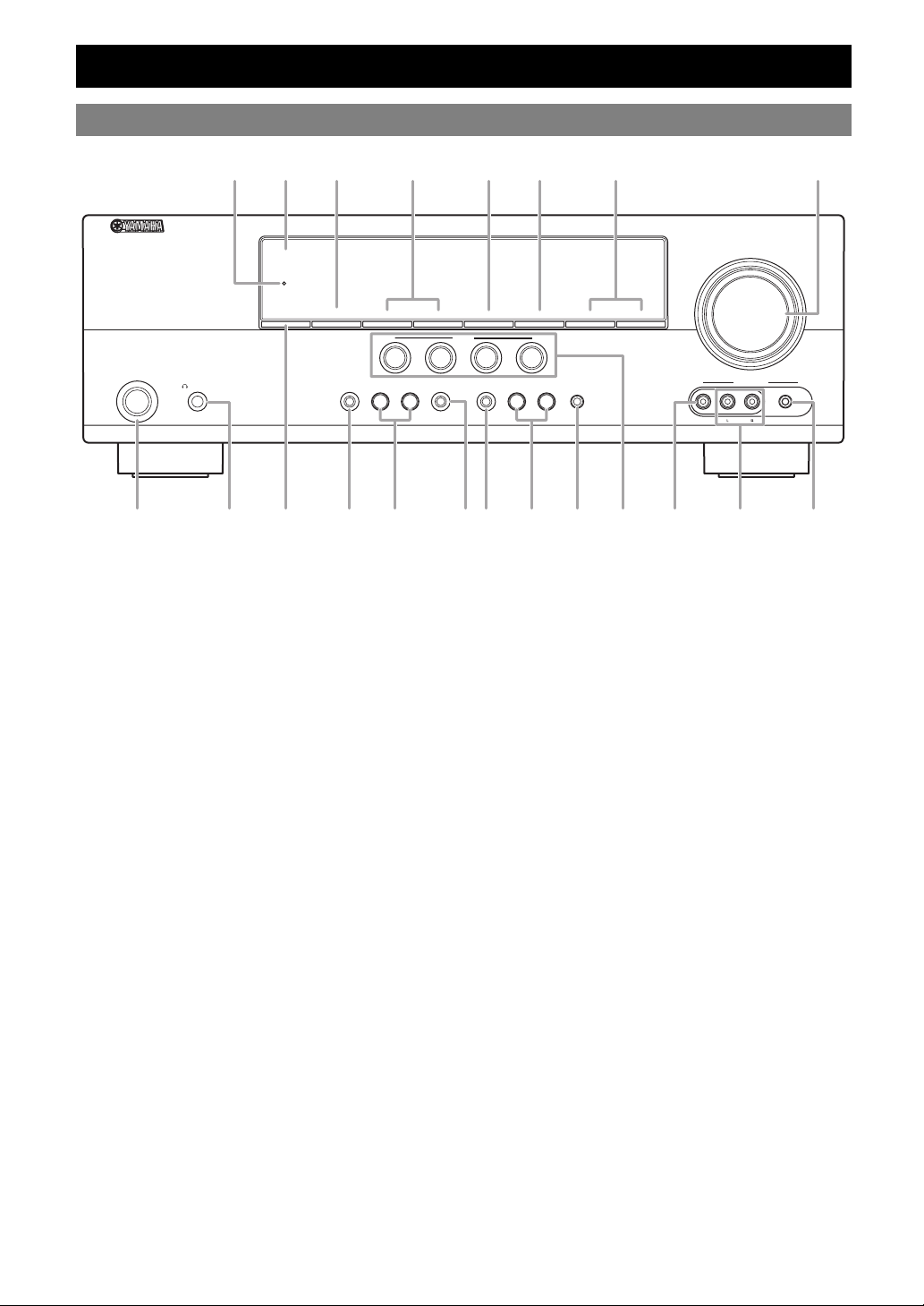
Front panel
T D G
U PFE H
Part names and functions
THROUGH
HDMI
VOLUME
MEMORY
INFO
CONTROL
STANDBY
A
PHONES
/ON
SILENT
CINEMA
TONE
J MC OK N
A STANDBY/ON
Switches this unit between standby and on (see page 17).
B PHONES jack
For plugging headphones (see page 22).
C INFO
Changes information display screens on the front panel display
(see page 23).
D MEMORY
Registers FM/AM stations as preset stations (see page 29).
E PRESET l / h
Selects an FM/AM preset station (see page 29).
F FM
Sets the FM/AM tuner band to FM (see page 28).
G AM
Sets the FM/AM tuner band to AM (see page 28).
H TUNING l / h
Changes FM/AM tuner frequencies (see page 28).
I SCENE
Switches between linked sets of input sources and sound field
programs (see page 21).
J TONE CONTROL
Adjusts high-frequency/low-frequency output of speakers/
headphones (see page 22).
K PROGRAM l / h
Changes sound field programs (see page 24).
L STRAIGHT
Changes a sound field program to straight decoding mode
(see page 27).
PROGRAM
l
l
BD/DVD
PRESET
h
FM
SCENE
TV
STRAIGHT
h
EFFECT
DIRECT
RADIO
CD
INPUT
l
l
h
OPTIMIZER
TUNING
AUX
MIC
VIDEO
VIDEO
AUDIO
PORTABLE
AM
h
I RBLQS
M DIRECT
Changes a sound field program to direct mode (see page 22).
N INPUT l / h
Selects an input source (see page 21).
O OPTIMIZER MIC jack
For connecting the supplied optimizer microphone and adjusting
output characteristics of speakers (see page 18).
P VOLUME control
Controls the volume of this unit (see page 21).
Q VIDEO (VIDEO AUX) jack
For connecting the video output cable of a camcorder or game
console (see page 16).
R AUDIO L/R (VIDEO AUX) jack
For connecting the audio output cable of a camcorder or game
console (see page 16).
S PORTABLE (VIDEO AUX) jack
For connecting the audio output cable of a portable music player
(see page 16).
T Front panel display
Displays information on this unit (see page 6).
U HDMI THROUGH
Lights up during pass-through output of an HDMI signal input
to this unit while this unit is on standby (see page 44).
4 En
Page 7
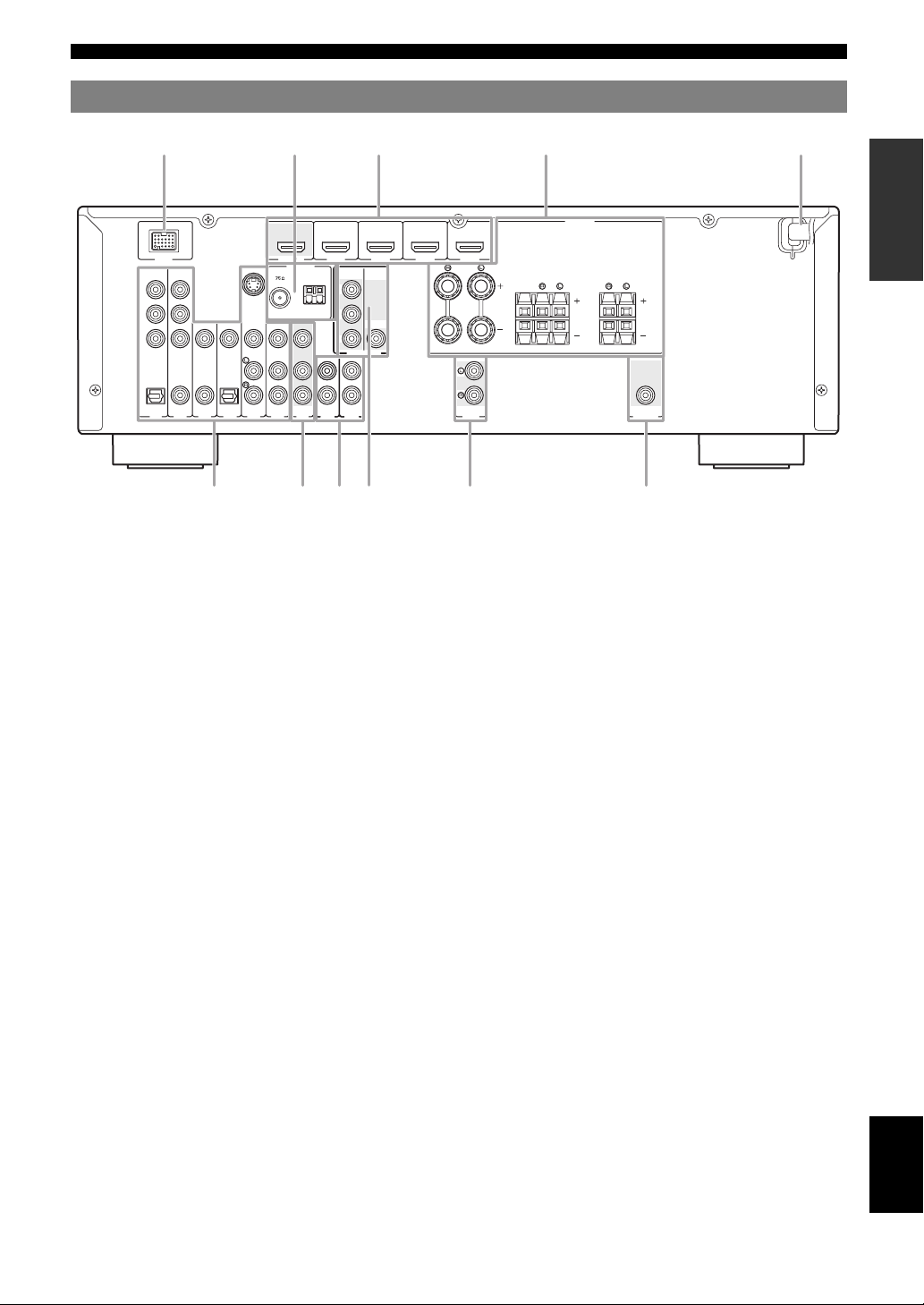
Rear panel
abc
efhgi j
kd
(
)
BD/DVD
S VIDEO
OUT
HDMI 1
HDMI
ANTENNA
COMPONENT
UNBAL.
FM
AV 6
AV 5
VIDEO
PR
GND
AM
PB
VIDEO
Y
MONITOR OUT
AV
AUDIO2
AUDIO1
OUT
DOCK
COMPONENT
VIDEO
PR
PB
Y
OPTICAL
(
TV
A
VIDEO
COAXIAL
COAXIAL
)
V
1
OPTICAL
(CD)
AV 2
AV 3
AV 4
a DOCK terminal
For connecting an optional Yamaha iPod universal dock (YDS-
11) or Bluetooth wireless audio receiver (YBA-10)
(see page 16).
b HDMI OUT/HDMI 1-4
For connecting an HDMI-compatible video monitor or external
components for HDMI inputs 1-4 (see page 15).
c ANTENNA jack
For connecting supplied FM and AM antennas (see page 17).
d SPEAKERS terminal
For connecting front right and left, center, surround and
surround back speakers (see page 11).
e AV 1 - 6
For connecting external components for audio/visual inputs 1-6
(see page 15).
f AV O U T
Outputs audio/visual signals from a selected analog input source
to an external component (see page 16).
g AUDI O 1 /2
For connecting external components for audio inputs 1-2
(see page 16).
h MONITOR OUT
Outputs visual signals from this unit to a video monitor, such as
a TV (see page 14).
i AUDI O O UT
Outputs audio signals from a selected analog input source to an
external component (see page 16).
j PRE OUT
For connecting a subwoofer with a built-in amplifier
(see page 11).
k Power Ca ble
For connecting this cable to an AC wall outlet (see page 17).
HDMI 2 HDMI 3
FRONT
HDMI 4
Part names and functions
INTRODUCTION
SPEAKERS
SURROUND
BACK/
CENTER
SURROUND
BI-AMP
PREPARATION
AUDIO
OUT
SUBWOOFER
PRE OUT
OPERATION
BASIC
OPERATION
ADVANCED
INFORMATION APPENDIX
ADDITIONAL
English
5 En
Page 8
Part names and functions
abcdef
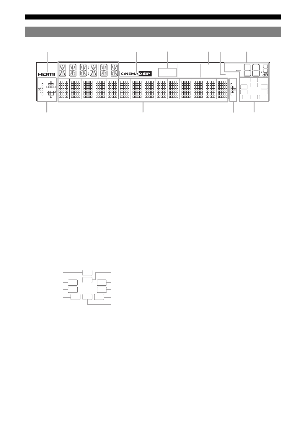
Front panel display
gh ig
a HDMI indicator
Lights up during normal communication when HDMI is
selected as an input source.
b CINEMA DSP indicator
Lights up when a sound field program that uses CINEMA DSP
is selected.
c Tuner indicator
Lights up while receiving a radio broadcast signal from an FM/
AM station (see page 28).
d SLEEP indicator
Lights up when the sleep timer is activated (see page 22).
e VOLUME indicator
Displays volume levels.
f MUTE indicator
Flashes when audio is muted.
g Cursor indicators
Light up if corresponding cursors on the remote control are
available for operations.
h Multi information display
Displays menu items and settings for the current operation.
i Speaker indicators
Indicate speaker terminals from which signals are currently
output.
STEREO
TUNED
SLEEP
VOL.
MUTE
SW
C
LR
SL SR
SBL SB SBR
Subwoofer
Front L
Surround L
Surround back L
SW
C
LR
SL SR
SBL SB SBR
Center
Front R
Surround R
Surround back R
Surround back
6 En
Page 9

a
Remote control
TRANSMIT
POWER
d
SOURCE
SLEEP
HDMI
1234
1234
g
V-AU X
[ A ] [ B ] DOCK
TUNER
FM
INFO
MOVIE
BD
DVD
AM
MEMORY
MUSIC
SCENE
TV
h
i
j
k
l
n
r
ENTER
RETURN
TOP
MENU
REC
1234
s
90
INPUT
t
a Remote control signal transmitter
Transmits infrared signals.
b TRANSMIT
Lights up when a signal is output from the remote control.
c CODE SET
Sets remote control codes for external component operations
(see page 46).
d SOURCE POWER
Switches an external component on and off.
e SLEEP
Switches the sleep timer operations (see page 22).
f POWER
Switches this unit on and standby.
MUTE
TV VOL
CODE SET
POWER
AV
AUDIO
1256
PRESET
TUNING
ENHANCER SUR. DECODE
STEREO
DIRECTSTRAIGHT
CD
RADIO
OPTIONSETUP
VOLUME
DISPLAY
MENU
7856
10
TV
POWER
TV CH
MUTE
ENT
e
q
b
c
f
m
o
p
Part names and functions
g Input selection keys
HDMI 1-4
AV 1 - 6
AUDIO 1/2
V-AUX
Selects HDMI inputs 1 through 4.
Selects AV inputs 1 through 6.
Selects AUDIO inputs 1 and 2.
Selects the V-AUX jack on the front
panel of this unit.
[A]/[B]
To control external components using
the rExternal component
operation keys separately from
operations of this unit (see page 46).
DOCK
Selects a Yamaha iPod universal dock/
Bluetooth wireless audio receiver
connected to the DOCK terminal.
TUNER
Selects the FM/AM tuner.
h Tuner keys
FM
Switches a band between FM and AM.
AM
MEMORY
PRESET k / n
TUNING k / n
Presets radio stations.
Selects a preset station.
Changes tuning frequencies.
i INFO
Changes the information shown on the front panel display
(see page 23).
j Sound selection keys
Selects sound field programs (see page 24).
k SCENE
Switches between linked sets of input sources and sound field
programs (see page 21).
l SETUP
Displays the setup menu (see page 41).
m OPTION
Displays the option menu (see page 35).
n Cursors k / n / l / h/ENTER/RETURN
Cursors k / n / l / h
Select menu items displayed on the
front panel display or on a video
monitor, or change settings.
ENTER
RETURN
Confirms a selected item.
Returns to the previous screen or
ends the menu display.
o VOLUME +/–
Adjust the volume of this unit (see page 21).
p DISPLAY
Changes the operation mode of the iPod connected to the
Yamaha iPod universal dock (see page 32).
q MUTE
Turns the mute function of the sound output on and off
(see page 22).
r External component operation keys
Operate recording, playback etc. of external components
(see page 46).
s Numeric keys
Enter numbers.
t TV control keys
Operate a monitor such as a TV or projector.
INTRODUCTION
PREPARATION
OPERATION
BASIC
OPERATION
ADVANCED
INFORMATION APPENDIX
ADDITIONAL
English
7 En
Page 10
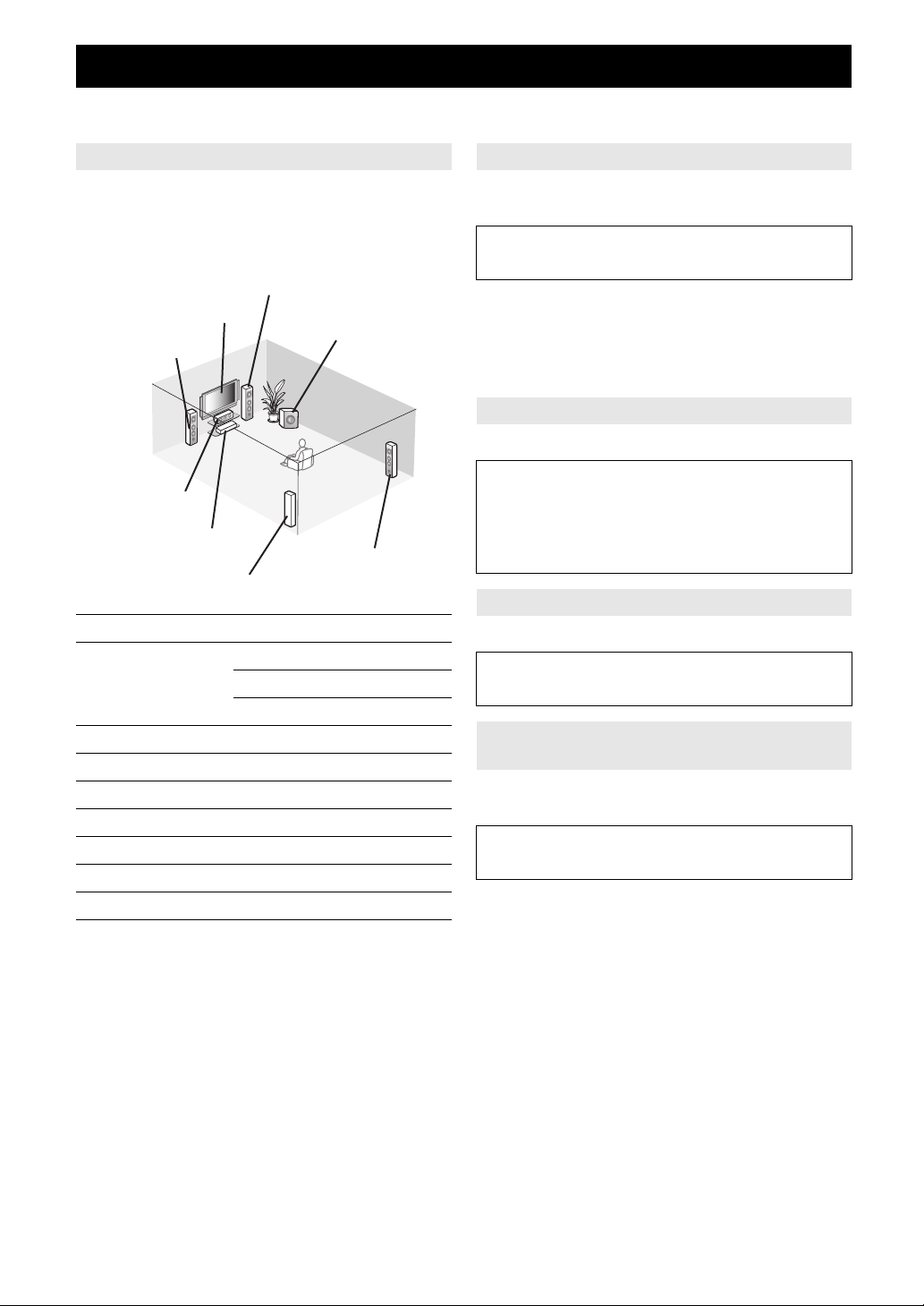
Quick start guide
When you use this product for the first time, perform setup following the steps below. See the related pages for details on
operations and settings.
Step 1: Prepare items for setup
Prepare speakers, DVD player, cables, and other items
necessary for setup.
For example, prepare the following items for setting up a
5.1-channel sound system.
Front right speaker
Video monitor
Front left speaker
Center speaker
Components
(such as DVD player)
Surround left speaker
Requirements qty.
Speakers Front speaker 2
Center speaker 1
Surround speaker 2
Active subwoofer 1
Speaker cable 5
Subwoofer cable 1
Reproduction component such as DVD player 1
Video monitor such as TV 1
Video cable or HDMI cable 2
Audio cable 2
y
• Prepare two speakers (for front). The priority of the requirement of other
speakers is as follows:
1 Two surround speakers
2 One center speaker
3 One (or two) surround back speaker(s)
• If your video monitor is a CRT, we recommend that you use magnetically
shielded speakers.
Subwoofer
Surround right speaker
Step 2: Set up your speakers
Place your speakers in the room and connect them to this
unit.
• Placing speakers ☞P. 1 0
• Connecting speakers ☞P. 1 1
y
• This unit has a YPAO (Yamaha Parametric Room Acoustic Optimizer)
that automatically optimizes this unit based on room acoustic
characteristics (audio characteristics of the speakers, speaker positions,
and room acoustics, etc.).
You can enjoy good balanced sound without special knowledge by using
the YPAO technology (see page 18).
Step 3: Connect your components
Connect your TV, DVD player, or other components.
• Connecting a TV monitor or projector ☞P. 1 4
• Connecting other components ☞P. 1 5
• Connecting a Yamaha iPod universal dock or
Bluetooth wireless audio receiver ☞P. 1 6
• Connecting the FM and AM antennas ☞P. 1 7
Step 4: Turn on the power
Connect the power cable and turn on this unit.
• Connecting the power cable ☞P. 1 7
• Turning this unit on and off ☞P. 1 7
Step 5: Select the input source and start
playback
Select the component connected in the step 3 as an input
source and start playback.
• Basic procedure ☞P. 2 1
• Selecting sound field programs ☞P. 2 4
y
• This unit supports the SCENE function that changes the input source and
sound field program at one time. Four scenes are preset for different
purposes for Blu-ray disc, DVD and CD, and you can select from a scene
from those just by pressing a remote control key. See page 21 for details.
8 En
Page 11
PREPARATION
Preparing remote control
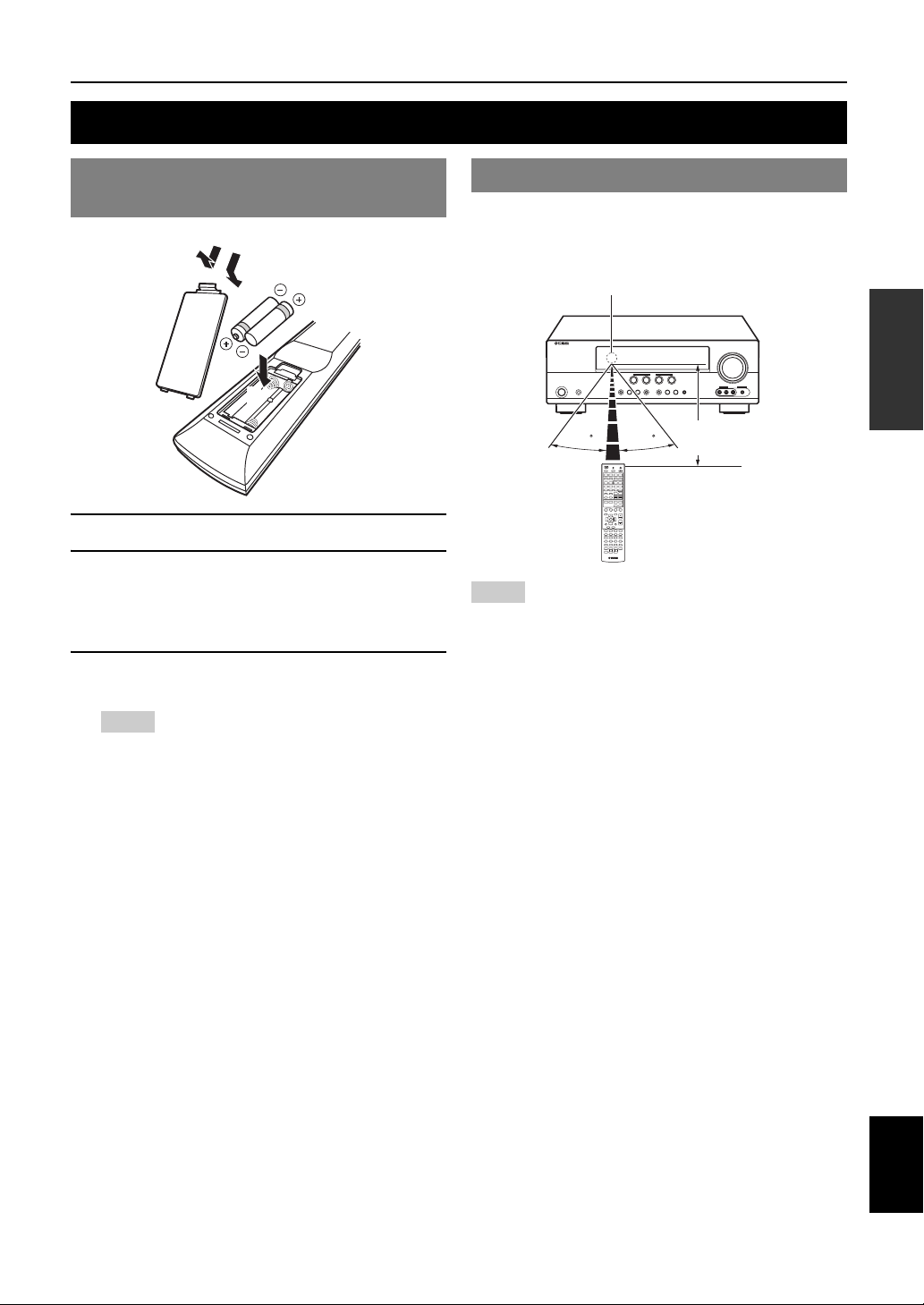
Installing batteries in the remote control
1
1 Take off the battery compartment cover.
2 Insert the two supplied batteries (AAA, R03,
UM-4) according to the polarity markings (+
and –) on the inside of the battery
compartment.
3 Snap the battery compartment cover back
into place.
Notes
• Change all batteries if you notice the following conditions:
– the operation range of the remote control narrows
– the transmit indicator does not flash or is dim
• Do not use old batteries together with new ones.
This may shorten the life of the new batteries or cause old batteries
to leak.
• Do not use different types of batteries (such as alkaline and
manganese batteries) together. Specification of batteries may be
different even though they look the same.
• If you find leaking batteries, discard the batteries immediately,
taking care not to touch the leaked material. If the leaked material
comes into contact with your skin or gets into your eyes or mouth,
rinse it away immediately and consult a doctor. Clean the battery
compartment thoroughly before installing new batteries.
• Dispose of the old batteries correctly in accordance with your local
regulations.
• If the remote control is without batteries for more than 2 minutes,
or if exhausted batteries remain in the remote control, the contents
of the memory may be cleared. In such a case, install new batteries
and set the remote control code.
3
2
Using the remote control
The remote control transmits a directional infrared ray. Be
sure to aim the remote control directly at the remote
control sensor on this unit during operation.
Remote control sensor window
within 6 m (20 ft)
30 30
Notes
• Do not spill water or other liquids on the remote control.
• Do not drop the remote control.
• Do not leave or store the remote control in the following conditions:
– places of high humidity, such as near a bath
– places of high temperatures, such as near a heater or stove
– places of extremely low temperatures
– dusty places
y
• You can operate external components with this remote control by setting
the remote control code. See page 46 for details.
INTRODUCTION
PREPARATION
OPERATION
BASIC
OPERATION
ADVANCED
INFORMATION APPENDIX
ADDITIONAL
9 En
English
Page 12
Connections
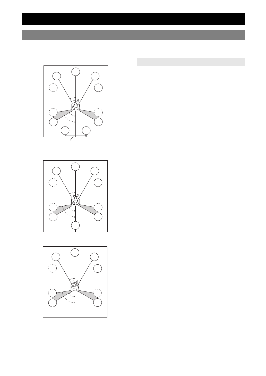
Placing speakers
This unit supports up to 7.1-channel surround. We recommend the following speaker layout in order to obtain the
optimum surround effect.
7.1-channel speaker layout
Speaker channels
80˚
SBL
C
30˚
60˚
FL
SW
SL
SL
30 cm (12 in) or more
6.1-channel speaker layout
FL
SW
SL
SL
C
30˚
60˚
80˚
SB
5.1-channel speaker layout
FL
SW
SL
SL
C
30˚
60˚
80˚
SBR
FR
■ Front left and right speakers (FL and FR)
The front speakers are used for the front channel sounds
(stereo sound) and effect sounds. Place these speakers at
SW
an equal distance from the ideal listening position. When
using a screen, the appropriate top positions of the
speakers are about 1/4 of the screen from the bottom.
SR
SR
■ Center speaker (C)
The center speaker is for the center channel sounds
(dialog, vocals, etc.). Place it halfway between the left and
right speakers. When using a TV, place the speaker just
above or just under the center of the TV with the front
surfaces of the TV and the speaker aligned. When using a
screen, place it just under the center of the screen.
■ Surround left and right speakers (SL and SR)
The surround speakers are used for effect and surround
sounds.
FR
SW
Place them at the rear left and rear right facing the
listening position.
To obtain a natural sound flow in the 5.1-channel speaker
layout, place them slightly further back than in the 7.1channel speaker layout.
■ Surround back left and right speakers (SBL
SR
and SBR) / Surround back speaker (SB)
The surround back left and right speakers are used for rear
SR
effect sounds. Place them at the rear of the room facing the
listening position at least 30 cm away from each other,
ideally at the same distance as that between the front left
and right speakers.
In the 6.1-channel speaker layout, surround back left and
right channel sound signals are mixed down and output
from the single surround back speaker.
FR
In the 5.1-channel speaker layout, surround back left and
right channel sound signals are output from the surround
SW
left and right speakers.
■ Subwoofer (SW)
The subwoofer speaker is used for bass sounds and lowfrequency effect (LFE) sounds included in Dolby Digital
SR
SR
and DTS signals. Use a subwoofer with a built-in
amplifier, such as the Yamaha Active Servo Processing
Subwoofer System. Place it exterior to the front left and
right speakers facing slightly inward to reduce reflections
from a wall.
10 En
Page 13
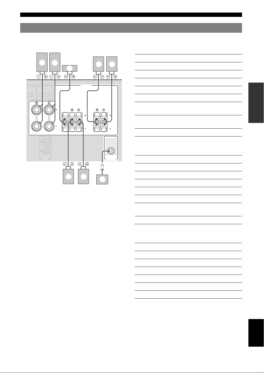
Connecting speakers
DMI 3
AUDIO
OUT
Connections
When you connect speakers, connect them to the respective terminals as follows, according to your speaker layout.
■ 7.1-channel
Speakers Jacks on this unit
b
a
c
g f
a Front speaker L FRONT (L)
b Front speaker R FRONT (R)
SPEAKERS
c Center speaker CENTER
d Surround speaker L SURROUND (L)
e Surround speaker R SURROUND (R)
FRONT
CENTER
SURROUND
SURROUND
BACK/
BI-AMP
f Surround back speaker L SURROUND
BACK/BI-AMP (L)
g Surround back speaker R SURROUND
BACK/BI-AMP (R)
h Subwoofer SUBWOOFER
■ 6.1-channel
SUBWOOFER
e d
h
PRE OUT
a Front speaker L FRONT (L)
b Front speaker R FRONT (R)
c Center speaker CENTER
d Surround speaker L SURROUND (L)
e Surround speaker R SURROUND (R)
f Surround back speaker SURROUND
h Subwoofer SUBWOOFER
Speakers Jacks on this unit
BACK/BI-AMP (L)
INTRODUCTION
PREPARATION
OPERATION
BASIC
OPERATION
ADVANCED
INFORMATION APPENDIX
ADDITIONAL
■ 5.1-channel
Speakers Jacks on this unit
a Front speaker L FRONT (L)
b Front speaker R FRONT (R)
c Center speaker CENTER
d Surround speaker L SURROUND (L)
e Surround speaker R SURROUND (R)
h Subwoofer SUBWOOFER
English
11 En
Page 14
Connections
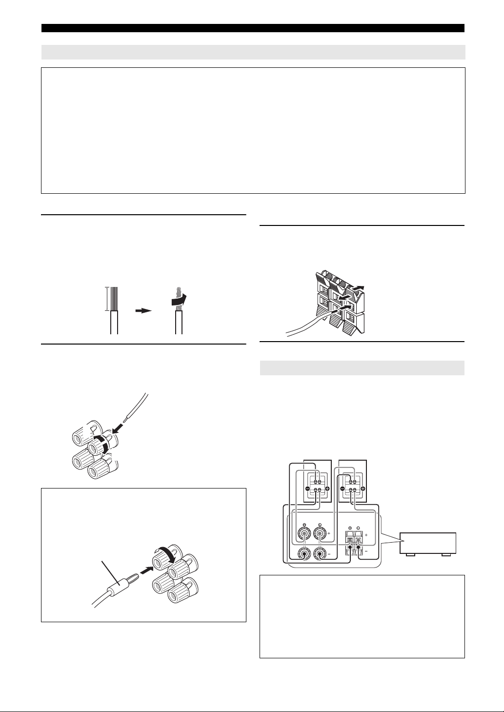
Connecting the speaker cable
Caution
• A speaker cable is a pair of insulated cables running side by side in general. One of the cables is colored differently
or striped to indicate a polarity. Connect one end of the colored/striped cable to the “+” (red) terminal of this unit
and the other end to that of your speaker, and connect one end of the other cable to the “–” (black) terminal of this
unit and the other end to that of your speaker.
• Before connecting the speakers, be sure to disconnect the power cable.
• Do not let the bare speaker wires touch each other or any metal part of this unit. This could damage this unit and/or
speakers. If the circuit shorts out, “CHECK SP WIRES!” appears on the front panel display when this unit is turned on.
• Use magnetically shielded speakers. If images on the monitor are still distorted even when you use the magnetically
shielded speakers, place the speakers away from the monitor.
• Use speakers with an impedance of 6-ohm or larger.
■ Connecting to the FRONT terminals
1 Remove approximately 10 mm (0.4 in) of
insulation from the end of each speaker
cable and then twist bare wires of the cable
together so that they will not cause a short
circuits.
10 mm (0.4 in)
2 Loosen the knob, insert the twisted bare
wires into the hole, and then tighten the
knob.
2
1
Red: positive (+)
Black: negative (–)
3
■ Connecting to the CENTER, SURROUND,
SURROUND BACK/BI-AMP terminals
1 Press down the tab and insert the bare end of
the speaker cable into the hole in the
terminal.
Red: positive (+)
Black: negative (–)
2 Release the tab to secure the wire.
Using bi-amplification connections
You can connect speakers that support bi-amplification
connections to this unit. Before connecting the speakers,
set this unit to enable bi-amplification connections in
“ADVANCED SETUP” (see page 47), and connect the
speakers to this unit as shown below.
Front speakers
Right Left
Connecting the banana plug (Except U.K.,
Europe, Asia and Korea models)
Tighten the knob, and then insert the banana plug into
the end of the terminal.
Banana plug
12 En
SURROUND
BACK/
FRONT
BI-AMP
This unit
Caution
Before making bi-amplification connections, remove
any or cables that connect a woofer with a tweeter.
Refer to the instruction manuals of speakers for details.
When not making bi-amplification connections, make
sure that the brackets or cables are connected before
connecting the speaker cables.
Page 15
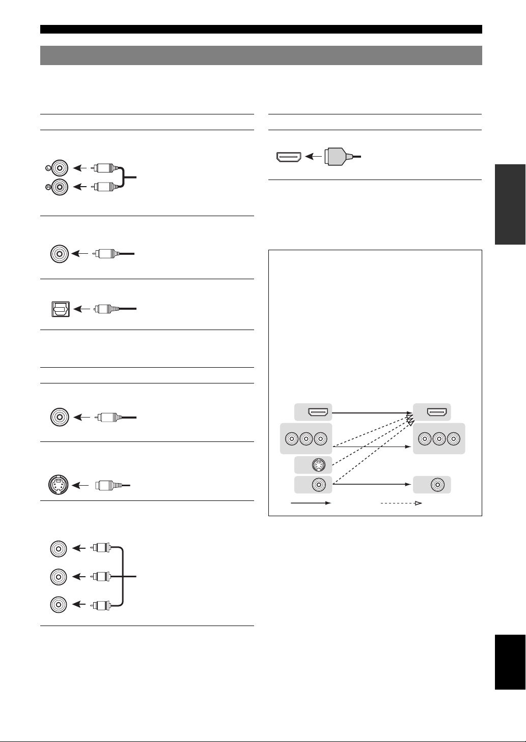
Information on jacks and cable plugs
Connections
This unit has the following input and output jacks. Use jacks and cables appropriate for components that you are
connecting.
■ Audio jacks
Jack and cables Description
AUDIO jacks To transmit conventional analog
(white)
L
R
AUDIO
(red)
COAXIAL jacks To transmit coaxial digital audio
(orange)
C
COAXIAL
OPTICAL jacks To transmit optical digital audio
OPTICAL
O
left and right audio signals. Use
stereo pin cables. Connect red
plugs to red jacks (R) and white
plugs to white jacks (L).
signals. Use pin cables for digital
audio signals.
signals. Use optical fiber cables for
optical digital audio signals.
■ Video/audio jacks
Jack and cables Description
HDMI jacks To transmit digital video and
digital audio signals. Use HDMI
HDMI
y
• We recommend that you use a commercially available 19-pin HDMI
cable no longer than 5 meters (16 feet) with the HDMI logo printed on it.
• You can check the potential problem about the HDMI connection (see
page 23).
• You can check error information on HDMI connections (see page 23).
HDMI
cables.
A video signal input to this unit is output from the
output terminals in MONITOR OUT for the same kind
of signal as the input signal.
For example, if a VCR with a composite output signal
and a DVD player with a COMPONENT VIDEO
output signal are connected, connect both VIDEO jack
and COMPONENT VIDEO jack in MONITOR OUT
to the video monitor.
If an HDMI input compatible monitor is connected, this
■ Video jacks
Jack and cables Description
VIDEO jacks To transmit conventional
VIDEO
V
(yellow)
composite video signals. Use video
pin cables.
unit automatically converts an analog signal that is
input from a video input terminal to a digital video
signal, and then output it from the HDMI OUT jack.
Input Output
HDMI
COMPONENT
VIDEO
HDMI
COMPONENT
VIDEO
INTRODUCTION
PREPARATION
OPERATION
BASIC
OPERATION
ADVANCED
INFORMATION APPENDIX
ADDITIONAL
S VIDEO jack To transmit S-video signals that
include luminance (Y) and
S VIDEO
S
COMPONENT VIDEO
jacks
COMPONENT
VIDEO
P
PR
(red)
PB
(blue)
Y
(green)
R
P
B
Y
chrominance (C) components. Use
S-video cables.
To transmit component video
signals that include luminance (Y),
chrominance blue (PB) and
chrominance red (PR) components.
Use component video cables.
P
R
P
B
Y
S VIDEO
VIDEO
Repeat Converted
P
VIDEO
R
P
B
Y
English
13 En
Page 16
Connections
MO
OUT
O
U
G
(
B
D
)
HD
OPTICAL
(
TV
)
S VIDEO
UNBAL.
GND
Y
AV 1
AV 2
COAXIAL
AV 3
(CD)
COAXIAL
OPTICAL
AV 5
AV
OUT
VIDEO
AV 6
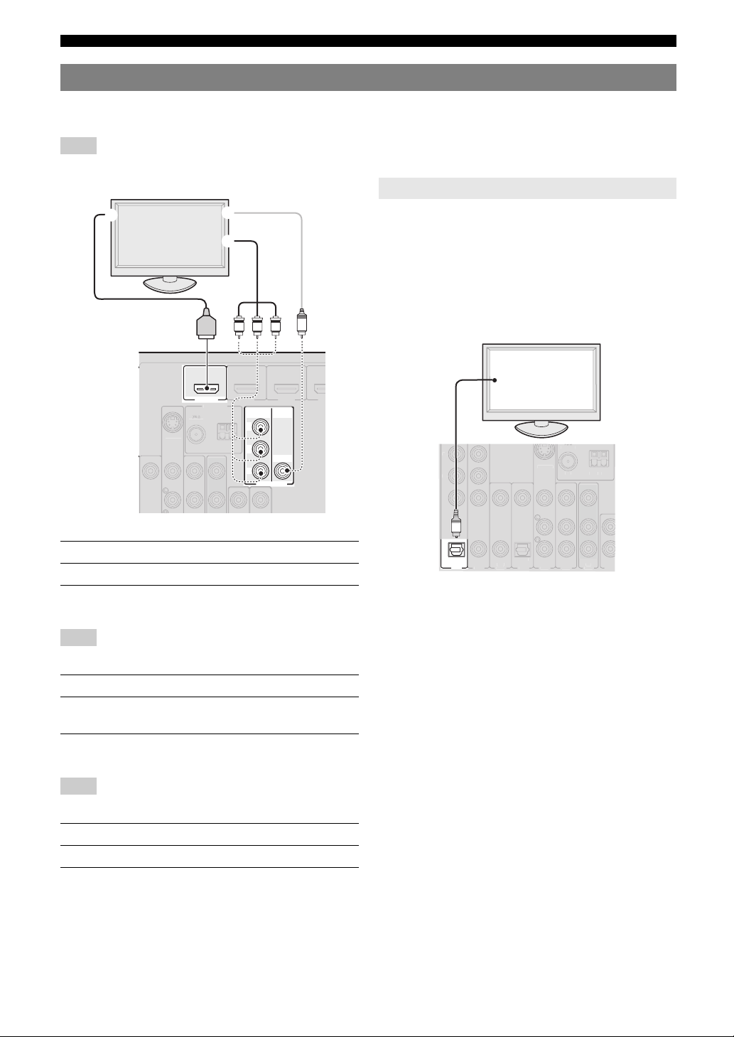
Connecting a TV monitor or projector
Connect a video monitor such as a TV or projector to an output terminal of this unit. You can select one of the following
three types according to the input signal format supported by the video monitor.
Note
• When you connect this unit to the video monitor, make sure that this unit is on standby.
TV, or projector
a
c
b
R
S VIDE
NBAL.
HDMI
HDMI
OUT
ND
PBYP
D/DV
COMPONENT
VIDEO
P
R
P
B
Y
NITOR
VIDEO
■ To connect an HDMI video monitor
Jacks on components Jacks on this unit
a HDMI input HDMI OUT
Outputting sound of a TV from this unit
To output sound of a TV from this unit, make connection
between the AV input 1-6 and an audio output terminal.
If the TV supports an optical digital output, we
recommend that you use the AV input 1. Connecting to the
AV input 1 allows you to switch an input source to the AV
input 1 with just a single key operation using the SCENE
function (see page 21).
V
O
TV, or projector
Digital output
(optical)
■ To connect component video monitor
Note
• Only video signals input from this unit via the component input terminal
are output from the component output terminal.
Jacks on components Jacks on this unit
b Component video output MONITOR OUT
(COMPONENT VIDEO)
■ To connect composite video monitor
Note
• Only video signals input from this unit via the composite video input
terminal are output from the composite video output terminal.
Jacks on components Jacks on this unit
c Video input (composite) MONITOR OUT (VIDEO)
14 En
Page 17
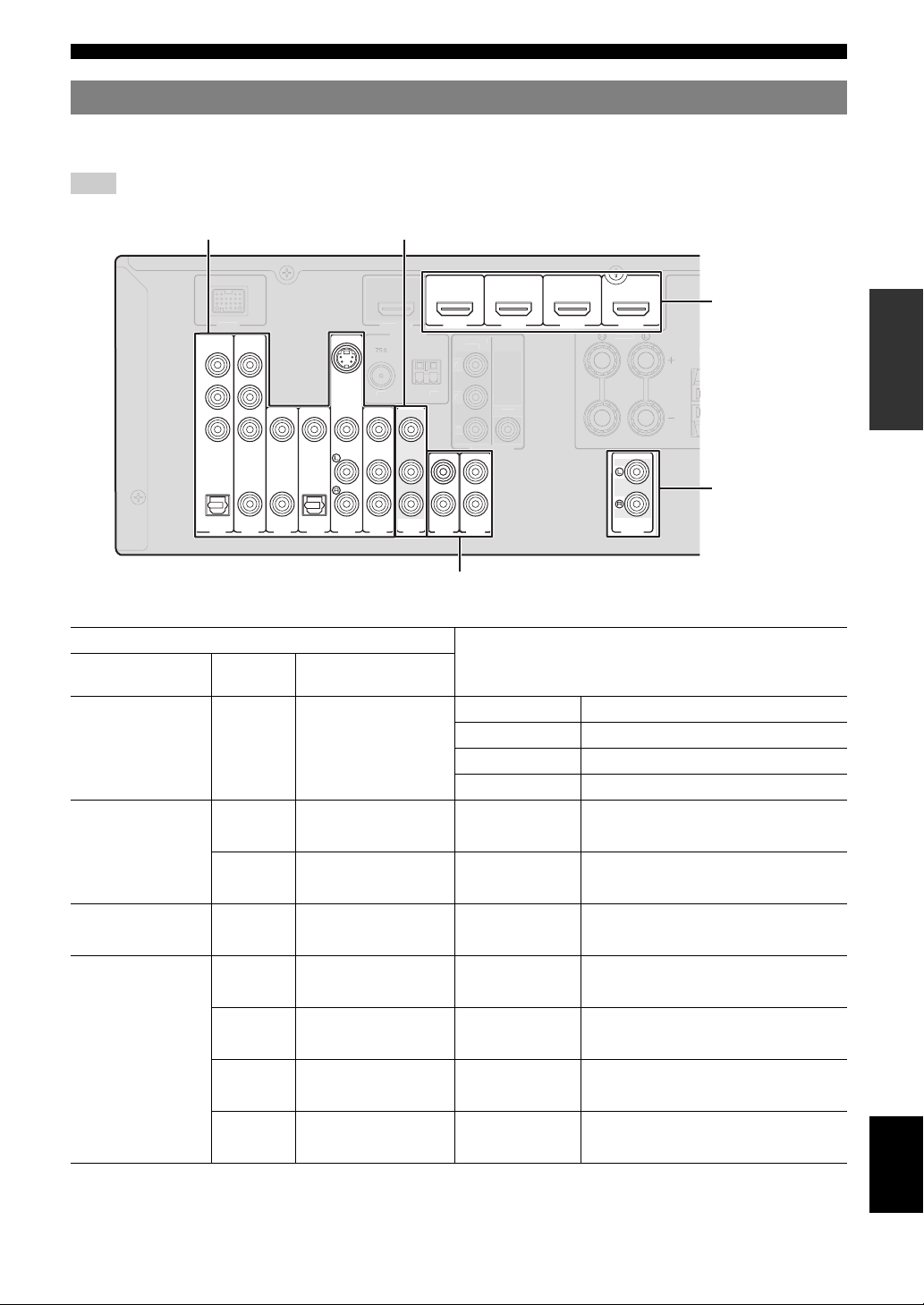
Connecting other components
H
H
HDMI 4
F
GND
M
COMPO
T
V
O
DOCK
HDMI
OUT
V
O
M
FRONT
C
Connections
This unit has input and output terminals for respective input and output sources. You can reproduce sound and movies
from input sources selected with the front panel display or remote control.
Note
• When you connect this unit to the external components, make sure that this unit is on standby.
Audio / video input (AV 1-6) Audio / video output (AV OUT)
HDMI input
(HDMI 1-4)
E
Audio output
(AUDIO OUT)
COMPONENT
VIDEO
P
R
P
B
Y
OPTICAL
(
TV
A
V 1
(
)
BD/DVD
UNBAL.
S VIDEO
M
A
VIDEO
COAXIAL
COAXIAL OPTICAL
)
(CD)
AV 2
AV 3
AV 4
AV 5
AV
AV 6
AUDIO1
OUT
NEN
IDE
ONITOR OUT
AUDIO2
DMI 2
IDE
DMI 3
AUDIO
OUT
Audio input (AUDIO 1-2)
■ Audio and video player / Set-top box
Output jacks on the connected external component
External
components
External component
with HDMI output
Signals Output jacks
Audio/Video HDMI output HDMI 1 (BD/DVD) HDMI 1
HDMI 2 HDMI 2
HDMI 3 HDMI 3
HDMI 4 HDMI 4
External component
with component video
output
Audio Optical digital output AV 1 (TV) OPTICAL
Video Component video output COMPONENT VIDEO
Audio Coaxial digital output AV 2 COAXIAL
Video Component video output COMPONENT VIDEO
External component
with S video output
External component
with composite video
output
Audio Analog audio output AV 5 AUDIO
Video S video output S VIDEO
Audio Coaxial digital output AV 3 (CD) COAXIAL
Video Composite output VIDEO
Audio Optical digital output AV 4 OPTICAL
Video Composite output VIDEO
Audio Analog audio output AV 5 AUDIO
Video Composite output VIDEO
Audio Analog audio output AV 6 AUDIO
Video Composite output VIDEO
y
• Input sources in parentheses are recommended to connect to the respective jacks. If a component is compatible with the SCENE function, you can switch
the input source to that component with a single key operation using the SCENE function (see page 21).
• You can change the name of the input source displayed on the front panel display or the OSD on the video monitor as necessary (see page 45).
Input sources/jacks of this unit
INTRODUCTION
PREPARATION
OPERATION
BASIC
OPERATION
ADVANCED
INFORMATION APPENDIX
ADDITIONAL
English
15 En
Page 18
Connections
DOCK
S
O
UNBAL
GND
ANTENNA
V
O
P
B
V
O
OUT
COMPO
OGRAM
S
INPUT
O
C
E
CT
D
CD
O
SC
PRES
l
T
G
AM
■ Audio player
Output jacks on the connected external component
External components Output jacks
External component with optical digital
output
External component with coaxial digital
output
External component with analog audio
output
Optical digital output AV 1 (TV) OPTICAL
AV 4 OPTICAL
Coaxial digital output AV 2 COAXIAL
AV 3 (CD) COAXIAL
Analog audio output AV 5 AUDIO
AV 6 AUDIO
AUDIO 1 AUDIO
AUDIO 2 AUDIO
y
• We recommend connecting the coaxial digital output terminal of a CD player to the AV3 jack.
Input sources/jacks of this unit
About audio/video output terminals
Among the analog audio and analog video signals input to this unit via input terminals, the audio/video signals of the
selected input sources are output from the AV OUT jack and AUDIO OUT jack. An HDMI input signal,
COMPONENT VIDEO input signal or digital audio input signal cannot be output.
When using the AV OUT jack: connect an external component to the composite or analog audio terminal.
When using the AUDIO OUT jack: connect an external component to the analog audio terminal.
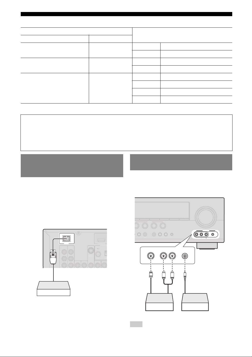
Connecting a Yamaha iPod universal dock or Bluetooth™ wireless audio receiver
This unit has the DOCK terminal, to which you can
connect a Yamaha iPod universal dock (YDS-11, sold
separately) or a Bluetooth wireless audio receiver (YBA10, sold separately). You can play an iPod or a Bluetooth
component with this unit by connecting it to the DOCK
terminal.
Use a dedicated cable for connection between the dock/
receiver and this unit.
NENT
IDE
Yamaha iPod universal
dock/Bluetooth wireless
audio receiver
IDE
.
VIDE
Using the VIDEO AUX jacks on the front panel
Use the VIDEO AUX jacks on the front panel to connect a
game console or a video camera to this unit. Be sure to
turn down the volume of this unit and other components
before making connections.
VOLUM
PTIMIZERMI
UNIN
AUX
VIDEO
VIDEO
AUDIO
PORTABLE
PORTABLE
RLAUDIO
Analog audio
output
R
ET
ENE
D/DV
TRAIGHT
EFFE
Video output
DIRECT
VIDEO
V
RADI
l
Analog audio
output
L
Game console/Camcorder Music player
Note
• When external components are connected both the PORTABLE jack and
AUDIO jack, sound input from the PORTABLE jack is output.
16 En
Page 19
Connections
S
O
COMPO
T
O
O
O
(
D
)
OU
O
OUT
COMPO
T
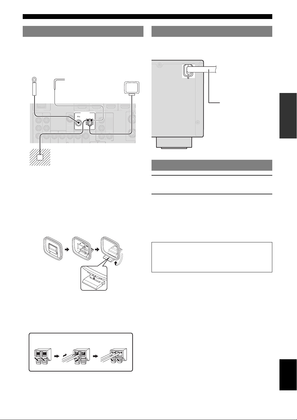
Connecting the FM and AM antennas
An indoor FM antenna and an AM loop antenna are
supplied with this unit. Connect these antennas properly to
the respective jacks.
Indoor FM antenna
DOCK
NEN
VIDE
P
Y
y
• The supplied antennas are normally sensitive enough to obtain good
reception.
• Position the AM loop antenna away from this unit.
• If you cannot get good reception, we recommend that you use an outdoor
antenna. For more details, consult the nearest authorized Yamaha dealer
or service center.
• Always use the AM loop antenna even when the outdoor antenna is
connected.
Assembling the AM loop antenna
Outdoor AM antenna
Connect a 5 to 10 m (16
to 33 ft) vinyl-covered
wire, and extend it
outdoors (use the AM
loop antenna together
with this antenna).
D/DV
VIDE
MONITOR
2
NEN
VIDE
T
UNBAL.
VIDE
VIDE
Ground (GND terminal)
The GND terminal is not for earth
grounding.
To reduce noises, connect a ground bar or a
vinyl-covered wire with a copper plate at its
tip, and place it in the moist ground.
GND
FM
AM
AM loop
antenna
3
Connecting the power cable
After all connections are complete, plug the AC power
cable of this unit into an AC wall outlet.
To the AC wall outlet
Power cable
Turning this unit on and off
1 Press ASTANDBY/ON (or fPOWER) to
turn on this unit.
2 Press ASTANDBY/ON (or fPOWER) again
to turn off this unit (standby mode).
y
• The unit needs a few seconds until ready to play back.
• You can also turn on this unit by pressing ISCENE (or kSCENE).
• This unit consumes a small amount of electricity even in the standby
mode. We recommend disconnecting the power cable from the AC wall
outlet.
Caution
Do not unplug this unit while it is turned on. Doing so
may damage this unit or cause the settings of this unit
to be saved incorrectly.
INTRODUCTION
PREPARATION
OPERATION
BASIC
OPERATION
ADVANCED
INFORMATION APPENDIX
ADDITIONAL
Connecting the AM loop antenna
The wires of the AM loop antenna have no polarity. You
can connect either wire to the AM terminal and the other
to the GND terminal.
Press and hold ReleaseInsert
English
17 En
Page 20
Optimizing the speaker setting for your listening room (YPAO)
V
O
A
O
O
UX
This unit has a Yamaha Parametric Acoustic Optimizer (YPAO). With the YPAO, this unit automatically adjusts the
output characteristics of your speakers based on speaker position, speaker performance, and the acoustic characteristics
of the room. We recommend that you first adjust the output characteristics with the YPAO when you use this unit.
Notes
• Be advised that it is normal for loud test tones to be
output during the “Auto Setup” procedure. Do not
allow small children to enter the room during the
procedure.
• To achieve the best results, make sure the room is as
quiet as possible while the “Auto Setup” procedure is
in progress. If there is too much ambient noise, the
results may not be satisfactory.
y
• See page 41 for the “Manual Setup” procedure.
Using Auto Setup
1 Check the following points.
Before starting the automatic setup, check the
following.
• All speakers and subwoofer are connected
properly.
• Headphones are disconnected from this unit.
• The video monitor is connected properly.
• This unit and the video monitor are turned on.
• This unit is selected as the video input source of the
video monitor.
• The connected subwoofer is turned on and the
volume level is set to about half way (or slightly
less).
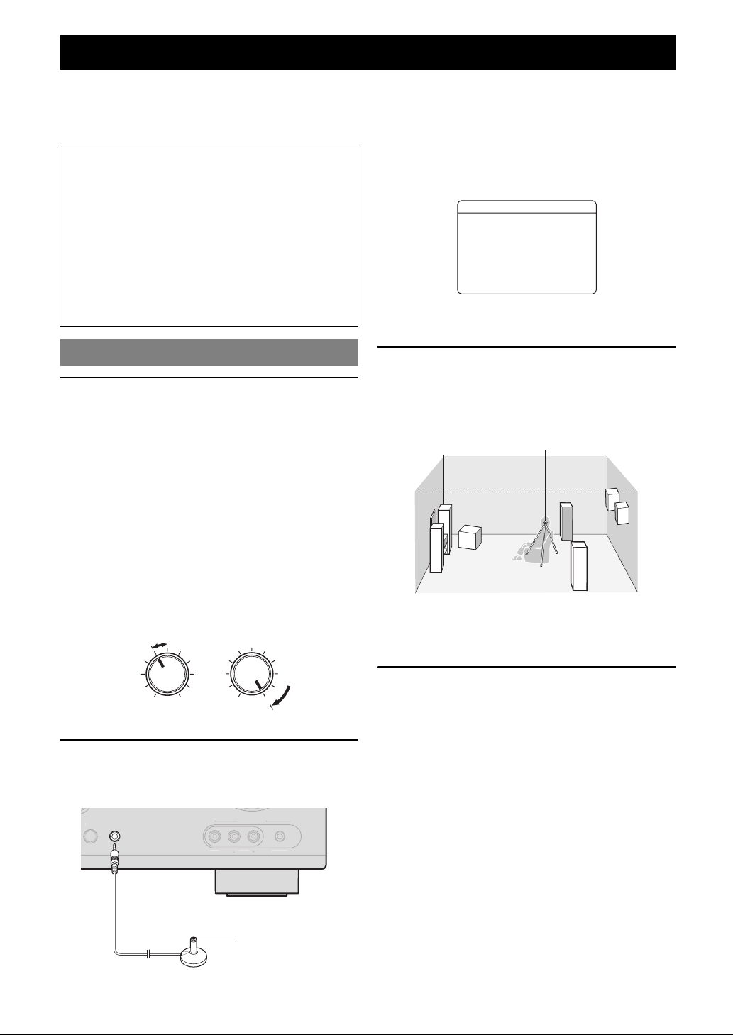
• The crossover frequency controls of the connected
subwoofer are set to the maximum.
CROSSOVER/
VOLUME
HIGH CUT
“MIC ON. View OSD MENU” appears on the front panel
display.
The following menu screen appears on the video monitor.
1 AutoSetup
EQ Type;;;;Natural
. Start
[
[
[]/[]:Up/Down
[ENTER]:Start
y
• You can bring up the above menu screen from the setup menu (see
page 41).
3 Place the optimizer microphone at your
normal listening position on a flat level
surface with the omni-directional
microphone heading upward.
Optimizer microphone
y
• It is recommended that you use a tripod or something similar to fix the
optimizer microphone at the same height as your ears would be when
seated in your listening position. You can fix the optimizer microphone to
the tripod with the attaching screw of the tripod.
4 To select a sound character for adjustment,
MIN MAX
Subwoofer
MIN MAX
2 Connect the supplied optimizer microphone
to the OPTIMIZER MIC jack on the front
panel.
A
OPTIMIZER
MIC
VIDE
IDE
UDI
Optimizer microphone
PORTABLE
press nCursor k to select “EQ Type” and
then press nCursor l / h.
If this unit does not work when you press nCursor,
press lSETUP once and then operate this unit.
This unit has a parametric equalizer that adjusts the
output levels for each frequency range. The equalizer
is adjusted to produce a cohesive sound field based on
automatically measured speaker characteristics.
In “EQ Type,” you can select the following
parametric equalizer characteristics suitable for the
desired sound characteristics.
Natural
This adjusts all speakers to achieve natural sound.
Select this if sounds in the high frequency range seem
too strong when “EQ Type” is set to “Flat.”
18 En
Page 21
Optimizing the speaker setting for your listening room (YPAO)
Flat
This adjusts each speaker to obtain the same
characteristics. Select this if your speakers have
similar qualities.
Front
This adjusts each speaker to obtain the same
characteristics as the front left and right speakers.
Select this if your front left and right speakers have
significantly better qualities than the other speakers.
5 Press nCursor n to select “Start” and then
press nENTER to start the setup procedure.
A countdown starts and a measurement starts in 10
seconds. A loud test tone is output during
measurement.
Notes
• During the automatic setup procedure, do not perform any
operation on this unit.
• Press nCursor k to cancel the automatic setup procedure.
Measurement takes about 3 minutes. To obtain precise
results, stay where you will not disturb the
measurement, such as to the side of or behind the
speakers or outside the room.
When measurement is successfully completed,
“YPAO Complete” appears on the front panel display
and the results appear on the monitor.
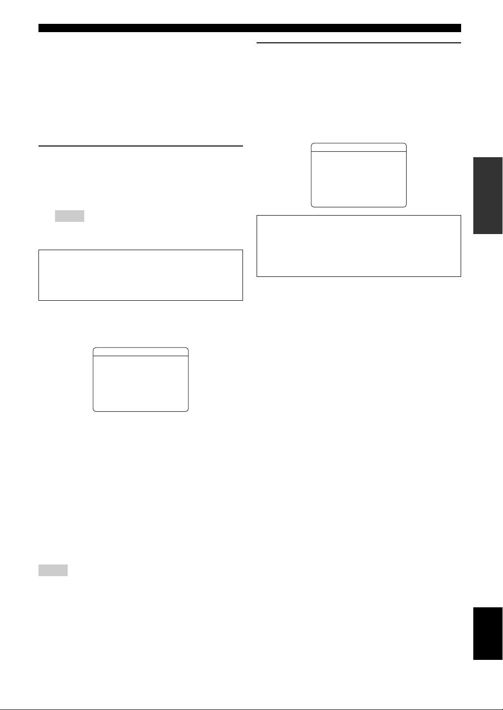
6 Press nENTER to confirm the settings.
The speaker characteristics are adjusted according to
measurement results.
To cancel the operation, press nCursor l / h to
select “Cancel” and press nENTER.
When the following screen appears, remove the
optimizer microphone. “Auto Setup” is now
complete.
1 AutoSetup
AUTOSETUPComplete
DisconnectMicrophone
PRESS[ENTER]
[SETUP]:Exit
The optimizer microphone is sensitive to heat. Store it
in a cool place and away from direct sunlight after
measurement. Do not leave it in a place where it will be
subjected to high temperatures such on an AV
component.
y
• If you do not want to apply the measurement results, select “Cancel.”
• Perform “Auto Setup” again if you change the number or positions of
speakers.
• If you press nENTER before removing the optimizer microphone,
“1 Auto Setup” of “Speaker Setup” in the setup menu (see page 41) is
displayed.
INTRODUCTION
PREPARATION
OPERATION
BASIC
OPERATION
ADVANCED
1 AutoSetup
RESULT
SP:3/4/0.1
DIST:2.50/3.00m
LVL:-3.5/+4.5dB
. >Set Cancel
[]/[]:Select
p[
[ENTER]:Finish
SP
Displays the number of speakers connected to this unit in
the following order:
Total of Front and Center/Total of Surround and Surround
Back/Subwoofer
DIST
Displays the speaker distance from the listening position
in the following order:
Closest speaker distance/Farthest speaker distance
LVL
Displays the speaker output levels in the following order:
Lowest speaker output level/Highest speaker output level
Notes
• If “ERROR” appears on the video monitor during “Auto Setup,”
measurement is canceled and the type of error is displayed. For details,
see “When an error message is displayed during measurement”
(page 20).
• If problems occur during measurement, “WARNING (XX)” (xx indicates
the number of warning) appears above “RESULT” (see page 20).
INFORMATION APPENDIX
ADDITIONAL
English
19 En
Page 22

Optimizing the speaker setting for your listening room (YPAO)
When an error message is displayed during measurement
Press nCursor n once, and select “Retry” or
“Exit” using nCursor l / h and then press
nENTER.
ERROR
.E-9:USER CANCEL
any function
>RetryExit
[ENTER]:Return
Retry
Performs “Auto Setup” again.
Exit
Terminates the measurement and “Auto Setup.”
y
• See page 53 for details on error messages.
• When “E-5:NOISY” appears, you can continue measurement. To
continue measurement, select “Proceed.” However, we recommend that
you solve the problem first and then perform measurement again.
operate
Don't
[]/[]:Select
p[
When a warning message is displayed after measurement
If a problem occurs during measurement, “WARNING” is
displayed on the result display screen. Check the error and
solve the problems.
WARNING
W-1:OUTOFPHASE
Reversechannel
FL--CENTER
SL--SBL--
[ENTER]:Return
y
• See page 54 for details on warning messages.
• Optimization will not be performed while a warning message is
displayed. We recommend that you solve the problem and perform “Auto
Setup” again.
1 Check if “→” is displayed on the left of
“WARNING” and press nENTER.
Details of the warning message are displayed. If there
are multiple warning messages, you can display the
next message using nCursor h.
2 To return to the top result display, press
nENTER again.
20 En
Page 23
BASIC OPERATION
Playback
Basic procedure
1 Turn o n e x t er n al co mponents (TV, DVD
player, etc.) connected to this unit.
2 Press NINPUT l / h (or gInput
selection keys) to select an input source.
The name of the selected input source is displayed for
a few seconds.
Input source name
VOL.
AV1
y
• You can change the input source name displayed on the front panel
display or the OSD on the video monitor as necessary (see
page 45).
3 Play the external component that you have
selected as the source input, or select a radio
station on the tuner.
Refer to the operating instructions of the external
component for details on playback. For selecting
radio stations or playback of an iPod or Bluetooth
component using this unit, see the following.
• FM/AM radio tuning (see page 28)
• Bluetooth component playback (see page 34)
• iPod playback (see page 32)
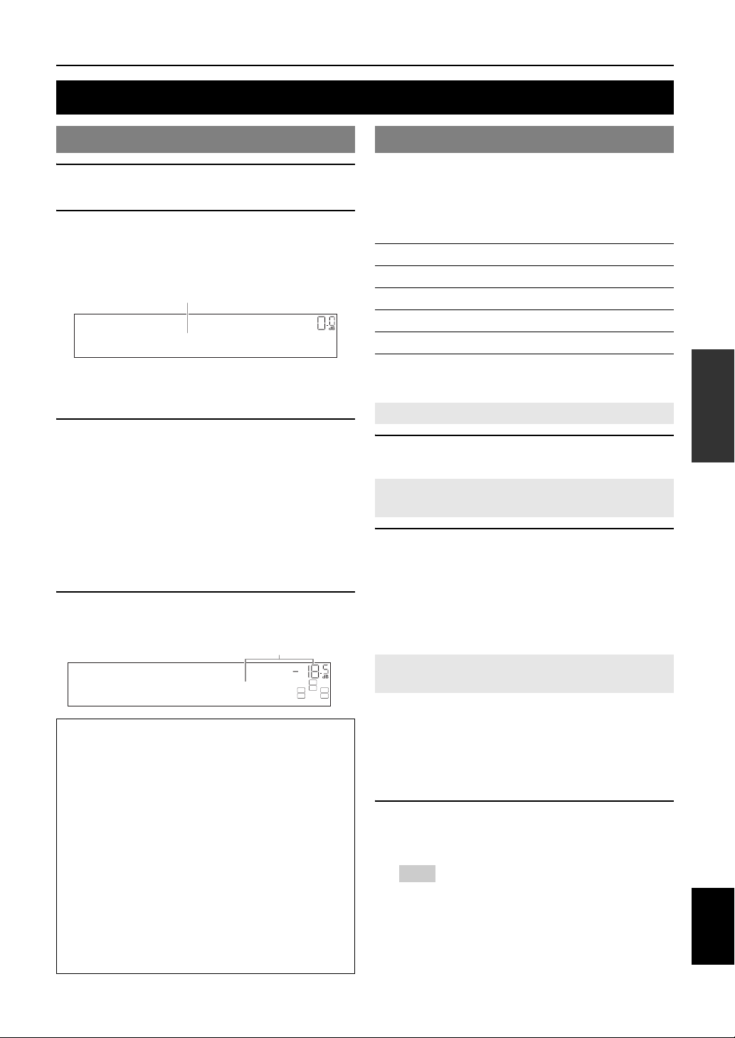
4 Turn t h e PVOLUME control to adjust the
volume (or press oVOLUME +/–).
Vol um e
VOL.
SW
C
LR
Volume-18.5dB
Note
When you play back a DTS-CD, noise may be output in some
conditions, which may cause a speaker malfunction. Make sure
that the volume is set to low before starting playback. If noise is
output, do the following.
1) When only noise is output
If a DTS bitstream signal is not properly input to this unit,
only noise is output. Connect the playback component to this
unit by digital connection and play back the DTS-CD. If the
condition is not improved, the problem may results from the
playback component. Consult the manufacturer of the
playback component.
2) When noise is output during playback or skip operation
Before playing back the DTS-CD, display the option menu
after selecting the input source and set “Decoder Mode” to
“DTS” (see page 35).
SL SR
Using the SCENE function
This unit has a SCENE function that allows you to change
input sources and sound field programs with one key. Four
scenes are available for different usages, such as playing
movies or music. The following input sources and sound
field programs are provided as the initial factory settings.
Input source Sound field program
BD/DVD HDMI 1 Straight
TV AV 1 Straight
CD AV 3 Straight
RADIO TUNER 7ch Enhancer
y
• When this unit is on standby, you can turn on this unit by pressing the
SCENE key.
Selecting a SCENE
Press ISCENE (or kSCENE).
Registering input source/sound field
program
Select the desired input source/sound field
program, and pressing down ISCENE (or
kSCENE) until “SET Complete” appears on the
front panel display.
While display in the OPTION menu or SETUP menu,
“SCENE Setting Complete” appears on the video monitor
(OSD).
Switching remotely controlled external
components linked to scene selections
You can operate an external component with the remote
control of this unit by setting a remote control code for the
external component for each input source. Setting remote
control codes for desired input sources allows you to
switch between external components linked to scene
selections.
1 Register the remote control code of an
external component to the desired input
source (see page 46).
Note
• Remote control codes cannot be registered to TUNER input.
INTRODUCTION
PREPARATION
OPERATION
BASIC
OPERATION
ADVANCED
INFORMATION APPENDIX
ADDITIONAL
English
21 En
Page 24
Playback
2 Press gInput selection keys on the
remote control for the input source whose
remote control code was registered in step 1
for about 3 seconds while pressing down
kSCENE key whose assignment you want
to change.
The external component can now be controlled
remotely just by selecting a scene.
Muting audio output temporarily (MUTE)
1 Press qMUTE on the remote control to mute
the audio output.
The MUTE indicator on the front panel display
flashes while audio output is muted.
2 Press qMUTE again to resume audio
output.
Adjusting high/low frequency sound (tone control)
You can adjust the balance of the high frequency range
(Treble) and low frequency range (Bass) of sounds output
from the front left and right speakers to obtain desired tone.
y
• The tone control of the speakers or headphones can be set separately. Set
the headphone tone control with the headphones connected.
1 Press JTONE CONTROL on the front panel
repeatedly to select “Treble” or “Bass.”
The current setting is displayed on the front panel
display.
Enjoying pure hi-fi sound
Use Direct mode to enjoy the pure high fidelity sound of
the selected source. When Direct mode is activated, this
unit plays back the selected source with the least circuitry.
Press MDIRECT (or jDIRECT) to turn the
Direct mode on or off.
The following features are disabled in Direct mode.
– sound field program, tone control
– display and operation of the option menu and setup
menu
y
• While direct mode is on, the front panel display screen becomes dim.
When setting it back off, the brightness of the screen returns to the
previous setting.
Using the sleep timer
The sleep timer is useful if you want to go to sleep while
this unit is playing or recording a source.
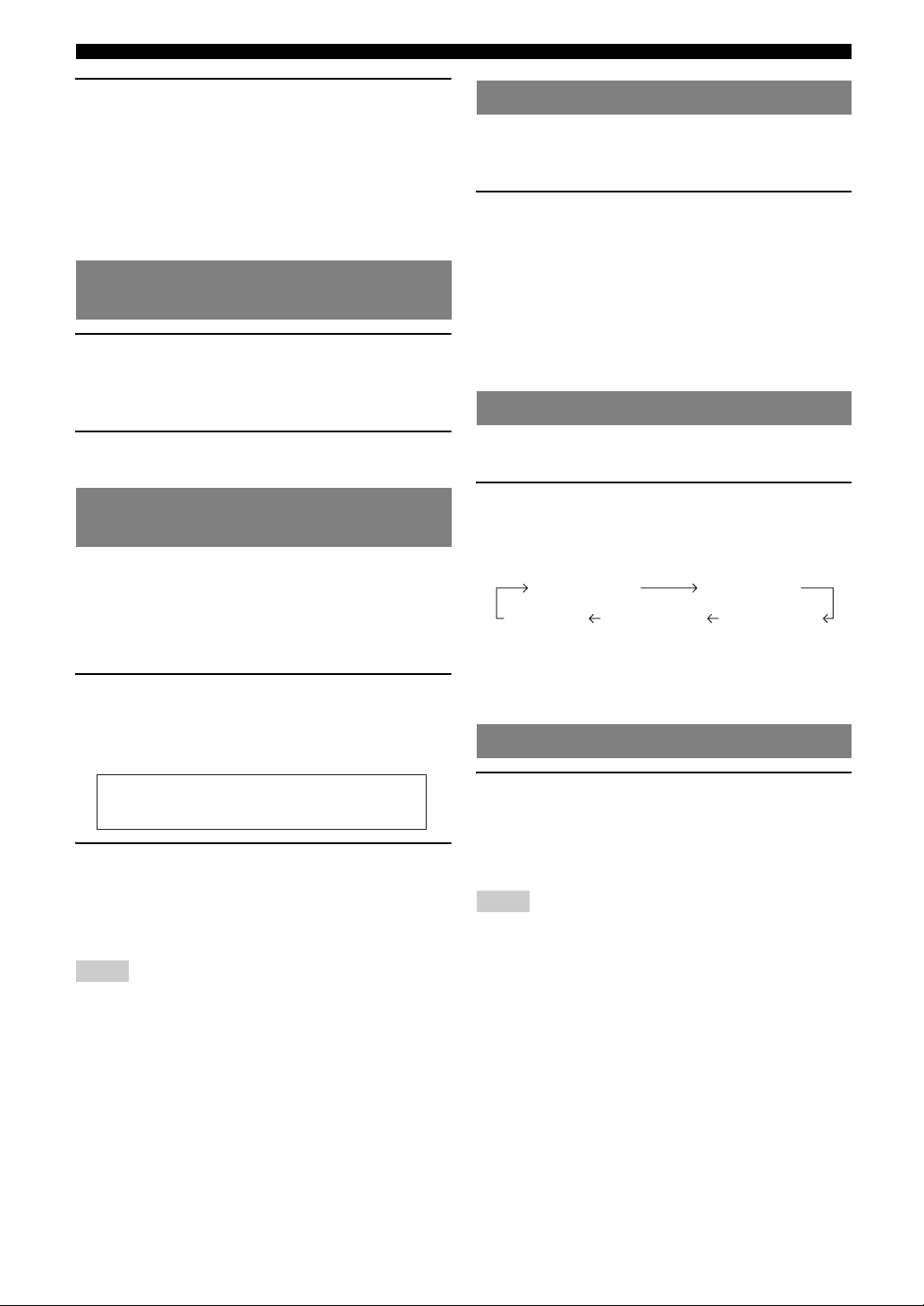
Press eSLEEP repeatedly to set the amount of
time.
Each time you press eSLEEP, the front panel display
changes as shown below.
Sleep 120min. Sleep 90min.
Sleep 60min.Sleep 30min.Sleep Off
When the sleep timer is set, the SLEEP indicator on the
front panel display lights up.
Press eSLEEP on the remote control repeatedly until
“Sleep Off” appears on the front panel display.
Using your headphones
Treble
0.0dB
2 Adjust the frequency range using
KPROGRAM l / h.
Control range: –10.0 dB to +10.0 dB
The display returns the previous screen soon after you
release the key.
Notes
• The tone control settings are not effective during playback in direct
mode.
• If you set the balance extremely off, sounds may not match those from
other channels well.
22 En
Plug your headphones in the BPHONES jack on
the front panel.
When you select a sound field program while using the
headphones, the mode is automatically set to SILENT
CINEMA mode.
Notes
• When you connect headphones, no signals are output at the speaker
terminals.
• When multi-channel signals are processed, sounds in all channels are
divided to left and right channels.
Page 25

Displaying input signal information Changing information on the front
When HDMI1-4 or AV1-4 is selected as the input source,
you can display audio/video signal information.
y
• Input signal information is displayed on both a video monitor and the
front panel display.
• Information on the input signal is also displayed on the front panel
display. You can select the desired item using nCursor k / n.
1 Select the desired input source, and press
mOPTION.
The option menu for the selected input source is
displayed (see page 35).
panel display
Information displayed on the front panel display can be
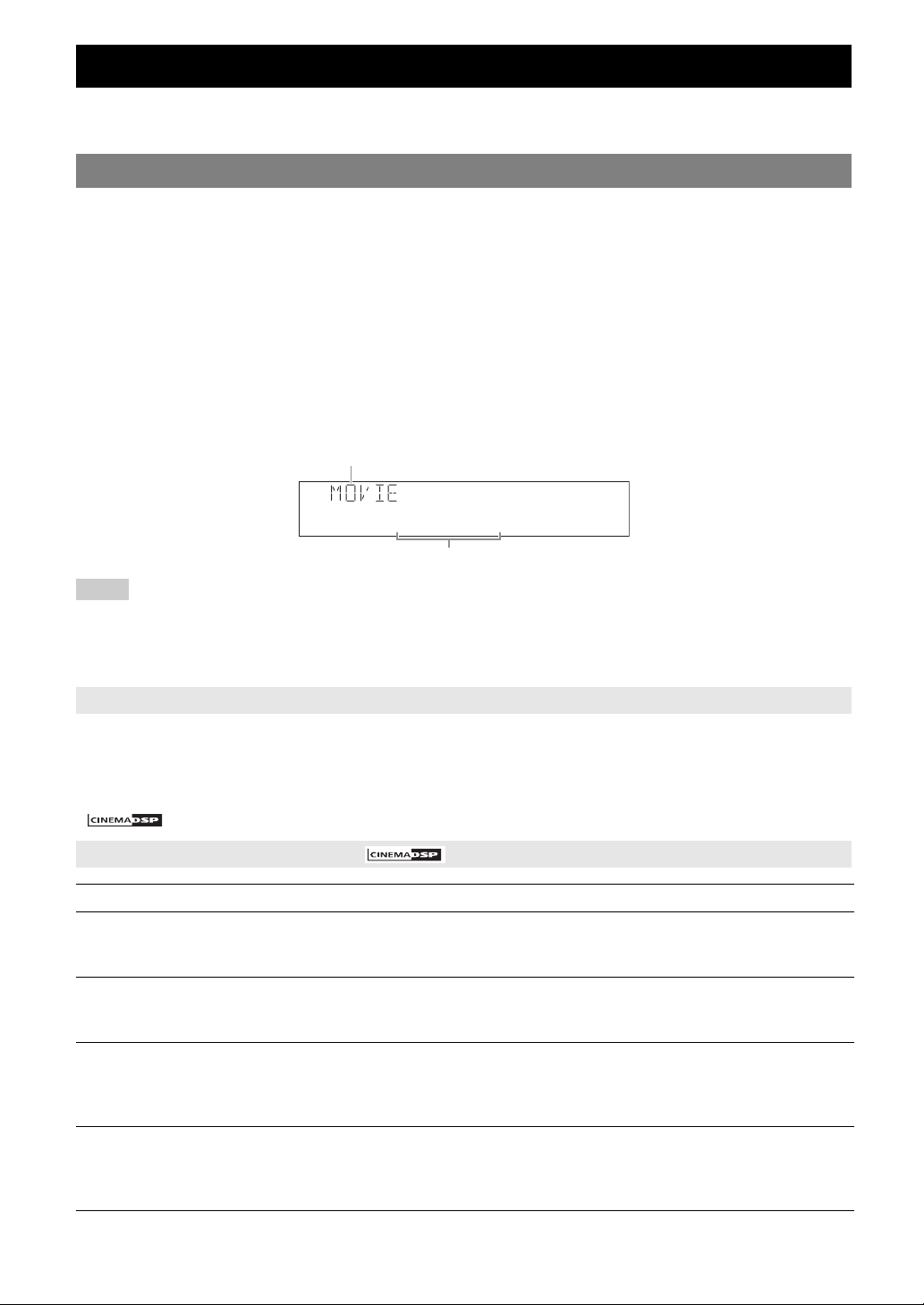
changed by pressing CINFO (or iINFO).
The following information can be displayed according to
the input source.
For example, if you select HDMI1 input and display “DSP
Program,” the following screen appears on the front panel
display.
Input source
Playback
INTRODUCTION
PREPARATION
2 Press nCursor k / n to select “Signal Info,”
and press nENTER.
Information on input signals is displayed. See
page 36 on messages displayed on the screen.
Notes
• If an HDMI related error occurs, error information is displayed at
the bottom of the screen.
• Information on the input signal is also displayed on the front panel
display. You can select the desired item using nCursor k / n.
3 To end the information display, press
mOPTION.
Straight
Sound field program (DSP program)
HDMI1-4: Input, DSP Program, Audio Decoder
AV1-6: Input, DSP Program, Audio Decoder
AUDIO1-2: Input, DSP Program, Audio Decoder
V-AUX: Input, DSP Program, Audio Decoder
FM/AM: Frequency, Program Service, Program
Type, Radio Text, Clock Time, DSP
Program, Audio Decoder
iPod (Simple remote mode): Input, DSP Program, Audio Decoder
iPod (Menu browse mode): (in PlayInfo displayed) Artist, Album,
Song, DSP Program, Audio Decoder
(in Play menu displayed) List
Bluetooth: Input, DSP Program, Audio Decoder
OPERATION
BASIC
OPERATION
ADVANCED
INFORMATION APPENDIX
ADDITIONAL
23 En
English
Page 26
Enjoy the sound field programs
This unit is also equipped with a Yamaha digital sound field processing (DSP) chip. You can enjoy multi-channel sounds
for almost all input sources using various sound field programs stored on the chip and a variety of surround decoders.
Selecting sound field programs
■ Selecting a sound field program on the front panel
Press KPROGRAM l / h repeatedly to select a desired sound field program.
■ Selecting a sound field program with the remote control
Perform the following operations depending on the category of the sound field programs.
Sound field programs for movies/TV programs ...............................Press jMOVIE repeatedly.
Sound field programs for music........................................................Press jMUSIC repeatedly.
Stereo reproduction ...........................................................................Press jSTEREO repeatedly.
Multi-channel stereo reproduction....................................................Press jSTEREO repeatedly.
Compressed music enhancer .............................................................Press jSTEREO repeatedly.
Surround decoder ..............................................................................Press jSUR.DECODE repeatedly.
For example, if you select “Sci-Fi” in “movie/TV program,” the following screen appears on the front panel display.
Sound field program category
Sci-Fi
Program name
Notes
• Sound field programs are stored for each input source. When you change the input source, the sound field program previously selected for that input
source is applied again.
• When you play back the Dolby Digital Plus, Dolby TrueHD, DTS Express, DTS-HD Master Audio, or DTS-HD High Resolution Audio sources, this unit
does not apply any sound field program other than the surround decoder and they are played back in straight decode mode.
• If the sampling frequency of an input source is higher than 96 kHz, this unit does not apply any sound field programs.
Sound field program descriptions
This unit provides sound field programs for multiple categories including music, movies and stereo reproduction. Select
a sound field program based on your listening preference, not merely on the name of the program, etc.
y
• You can check what speakers are currently outputting signals with the speaker indicators on the front panel display (see page 6).
• Each program can adjust sound field elements (sound field parameters). For details, see page 38.
• in the table indicates the sound field program with CINEMA DSP.
For movie/TV program sources
Program Descriptions
Standard This program creates a sound field emphasizing the surrounding feeling without disturbing the original acoustic
positioning of multi-channel audio such as Dolby Digital and DTS. It has been designed with the concept of “an
ideal movie theater,” in which the audience is surrounded by beautiful reverberations from the left, right and rear.
Spectacle This program represents the spectacular feeling of large-scale movie productions.
It reproduces a broad theater sound field matching the cinemascope and wider-screen movies with an excellent
dynamic range from very small to extremely large sound.
Sci-Fi This program clearly reproduces the finely elaborated sound design of the latest science fiction and special effects-
featuring movies.
You can enjoy a variety of cinematographically created virtual spaces reproduced with clear separation between
dialog, sound effects and background music.
Adventure This program is ideal for precisely reproducing the sound design of action and adventure movies.
The sound field restrains reverberations but puts emphasis on reproducing a powerful space expanded widely to
the left and right. The reproduced depth is also restrained relatively to ensure the separation between audio
channels and the clarity of the sound.
24 En
Page 27

Enjoy the sound field programs
Program Descriptions
Drama This sound field features stable reverberations that match a wide range of movie genres from serious dramas to
musicals and comedies. The reverberations are modest but offer an optimum 3D feeling, reproducing effects tones
and background music softly but cubically around clear words and center positioning in a way that does not fatigue
the listener even after long hours of viewing.
Mono Movie This program is provided for reproducing monaural video sources such as a classic movie in an atmosphere of a
good old movie theater.
The program produces the optimum expansion and reverberation to the original audio to create a comfortable
space with a certain sound depth.
Sports This program allows the listeners to enjoy stereo sport broadcasts and studio variety programs with enriched live
feeling. In sports broadcasts, the voices of the commentator and sportscaster are positioned clearly at the center
while the atmosphere of the stadium expands in an optimum space to offer the listeners with a feeling of presence
in the stadium.
Action Game This sound field has been suitable for action games such as car racing and FPS games. It uses the reflection data
that limits the effects range per channel in order to offer a powerful playing environment with a being-there feeling
by enhancing various effects tones while maintaining a clear sense of directions.
Roleplaying Game This sound field has been suitable for role-playing and adventure games. It combines the sound field effects for
movies and the sound field designs for “Action Game” to represent the depth and 3D feeling of the field during
play, while offering movie-like surround effects in the movie scenes in the game.
For audio music sources
Program Descriptions
Hall in Munich This sound field simulates a concert hall with approximately 2500 seats in Munich, using stylish wood for the
interior finishing as normal standards for European concert halls. Fine, beautiful reverberations spread richly,
creating a calming atmosphere. The listener’s virtual seat is at the center left of the arena.
Hall in Vienna This is an approximately 1700-seated, middle-sized concert hall with a shoebox shape that is traditional in Vienna.
Pillars and ornate carvings create extremely complex reflections from all around the audience, producing a very
full, rich sound.
Chamber This program creates a relatively wide space with a high ceiling like an audience hall in a palace. It offers pleasant
reverberations that are suitable for courtly music and chamber music.
Cellar Club This program simulates a live house with a low ceiling and homey atmosphere. A realistic, live sound field
features powerful sound as if the listener is in a row in front of a small stage.
The Roxy Theatre This is the sound field of a rock music live house in Los Angeles, with approximately 460 seats. The listener’s
virtual seat is at the center left of the hall.
The Bottom Line This is the sound field at stage front in The Bottom Line, that was a famous New York jazz club once. The floor
can seat 300 people to the left and right in a sound field offering real and vibrant sound.
Music Video This sound field offers an image of a concert hall for live performance of pop, rock and jazz music. The listener
can indulge oneself in a hot live space thanks to the presence sound field that emphasizes the vividness of vocals
and solo play and the beat of rhythm instruments, and to the surround sound field that reproduces the space of a
big live hall.
INTRODUCTION
PREPARATION
OPERATION
BASIC
OPERATION
ADVANCED
INFORMATION APPENDIX
ADDITIONAL
For stereo reproduction
Program Descriptions
2ch Stereo Use this program to mix down multi-channel sources to 2 channels.
y
• When multi-channel signals are input, they are downmixed to 2 channels and output from the front left and right speakers.
English
25 En
Page 28
Enjoy the sound field programs
For Multi-channel stereo reproduction
Program Descriptions
7ch Stereo Use this program to output sound from all speakers. When you play back multi-channel sources, this unit
downmixes the source to 2 channels, and then outputs the sound from all speakers. This program creates a larger
sound field and is ideal for background music at parties, etc.
The Compressed Music Enhancer
Program Descriptions
Straight Enhancer Use this program to enhance the sound nearest to the original depth and width of the 2-channel or multi-channel
compression artifacts.
7ch Enhancer Use this program to play back compression artifacts in 7-channel stereo.
Surround decode mode
Select this program to playback sources with selected decoders. You can playback 2-channel sources on multi-channels.
Decoder Descriptions
Pro Logic Dolby Pro Logic decoder suitable for all kinds of sources.
PLIIx Movie /
PLII Movie
PLIIx Music /
PLII Music
PLIIx Game /
PLII Game
Neo:6 Cinema DTS decoder suitable for movies.
Neo:6 Music DTS decoder suitable for music.
Dolby Pro Logic IIx (or Dolby Pro Logic II) decoder suitable for movies. If your listening environment is as
follows, you cannot select the Dolby Pro Logic IIx decoder.
• When the surround back speakers are not connected
• When headphones are connected
Dolby Pro Logic IIx (or Dolby Pro Logic II) decoder suitable for music. If your listening environment is as
follows, you cannot select the Dolby Pro Logic IIx decoder.
• When the surround back speakers are not connected
• When headphones are connected
Dolby Pro Logic IIx (or Dolby Pro Logic II) decoder suitable for games. If your listening environment is as
follows, you cannot select the Dolby Pro Logic IIx decoder.
• When the surround back speakers are not connected
• When headphones are connected
y
• An input source is played back in straight decode mode (see page 27) when multi-channel audio signal is input.
26 En
Page 29

Enjoy the sound field programs
Enjoying unprocessed input sources (Straight decoding mode)
In straight decoding mode, sounds are reproduced without
sound field effect. 2-channel stereo sources are output
from only the front left and right speakers. Multi-channel
input sources are decoded straight into the appropriate
channels and multi-channel sounds are reproduced
without a sound field effect.
1 To enable straight decoding mode, press
LSTRAIGHT (or jSTRAIGHT).
“Straight” appears on the front panel display.
2 To cancel straight decoding mode, press
LSTRAIGHT (or jSTRAIGHT) again.
A sound field program name appears on the front
panel display, and sound is reproduced with that
sound field effect.
Enjoying sound field programs without surround speakers (Virtual CINEMA DSP)
Virtual CINEMA DSP allows you to enjoy DSP sound
field surround effects even without any surround speakers
by using virtual surround speakers. You can even enjoy
Virtual CINEMA DSP using a minimal two-speaker
system that does not include a center speaker.
When “Sur. L/R SP” in the setup menu is set to “None”
(see page 42), this unit operates in Virtual CINEMA DSP
mode.
Enjoy sound field programs with headphones (SILENT CINEMA™)
SILENT CINEMA allows you to enjoy multi-channel
sources with your headphones. SILENT CINEMA mode
is automatically selected when you connect the headphone
plug to the PHONES jack.
Note
• SILENT CINEMA mode is not available in the following conditions.
– 2ch Stereo of the sound field program is selected.
– direct mode or straight decoding mode is selected.
INTRODUCTION
PREPARATION
OPERATION
BASIC
OPERATION
ADVANCED
Note
• Virtual CINEMA DSP mode is not available in the following conditions
even if you set “Sur. L/R SP” to “None” (see page 42).
– headphone plug is connected to the PHONES jack.
– 7ch Stereo of the field sound program is selected.
– direct mode or straight decoding mode is used.
INFORMATION APPENDIX
ADDITIONAL
English
27 En
Page 30
FM/AM tuning
The FM/AM tuner of this unit provides the following two
modes for tuning.
■ Frequency tuning mode (Auto tuning /
Manual tuning)
You can tune in to a desired FM/AM station by searching
or specifying its frequency.
■ Preset tuning mode (Preset tuning)
You can preset the frequencies of FM/AM stations by
registering them to specific numbers, and later just select
those numbers to tune in.
Note
• Adjust the FM/AM antennas connected to this unit for the best reception.
Tuning in to the desired FM/AM station (Frequency tuning)
1 Press NINPUT l / h (or gTUNER)
repeatedly and switch the input source to
“TUNER.”
2 Press FFM (hFM) or GAM (hAM) to select
a band.
“FM” or “AM” appears on the front panel display
according to the band that you have selected.
3 Press HTUNING l / h (or hTUNING k /
n) to specify the frequency.
To adjust the frequency to a higher range, press h (or
k). To adjust it to the lower range, press l (or n).
The TUNED indicator on the front panel display
lights up when the tuner is tuned in to a station. The
STEREO indicator also lights up if the program being
broadcasted is in stereo.
STEREO
TUNED
FM92.50MHz
The frequency changes in the following manner according
to how you press HTUNING l / h (or hTUNING k
/ n).
When you press the key more than 1 second
The tuner searches the frequency of a station that is
detectable around the current frequency. This is effective
when the tuner can receive strong signals without any
interference. Once the search starts, release the key.
When you keep holding the key, the search continues even
when a station is detected. This is useful when you want to
tune in to a specific station.
When you press and release the key
The tuner increases or decreases the frequency in steps.
Use this method when the tuner cannot receive strong
signals and stations are skipped during the search. You can
listen to better quality sound even when the tuner cannot
receive a strong signal.
y
• You can switch between stereo and monaural for FM broadcast in the
option menu (see page 36).
4 To tune in by direct frequency tuning, enter
the frequency of the desired station using
the numeric keys on the remote control.
Enter only integers. For example, if you want to set
the frequency to 88.90 MHz, enter “8890” using
sNumeric keys.
Notes
• When you press sNumeric keys during preset tuning, a
preset number is selected. Set tuning mode to normal tuning mode
using HTUNING l / h (or hTUNING k / n) prior to the
operation.
• “Wrong Station!” appears on the front panel display when you
enter a frequency that is out of receivable range. Make sure that the
entered frequency is correct.
• You do not need enter zero if it comes at the end of a decimal
number. For example, enter “925” for “92.50 MHz” or “940” for
“94.00MHz.”
Registering FM/AM stations and tuning in (Preset tuning)
You can register up to 40 FM/AM stations (Preset) using
“Automatic station preset” or “Manual station preset.”
Registering stations by automatic station
preset
The tuner automatically detects FM stations with strong
signals and registers up to 40 stations. AM stations cannot
be automatically registered. Use manual station preset.
1 Press NINPUT l / h repeatedly (or press
gTUNER) to switch the input source to
“TUNER.”
2 Press mOPTION on the remote control.
The option menu screen for setting options of tuner
input appears on the front panel display.
y
• For details on the option menu, see page 35.
• The option menu is displayed on monitor components.
3 Select “Auto Preset,” and press nENTER.
Auto Preset
Automatic station preset starts about 5 seconds later
from the lowest frequency upwards.
28 En
Page 31

FM/AM tuning
y
• You can select the preset number at which the preset starts by
pressing hPRESET k / n or nCursor k / n while the front
panel display is in the state as shown in the below figure.
• To cancel registration, press nRETURN on the remote control.
Status
01:FM87.50MHz
Preset number Frequency
During the automatic station preset, the upper area of
the screen changes as follows: READY → SEARCH
→ MEMORY each time a station is registered.
When registration is complete, “FINISH” appears
and the option menu screen automatically reappears.
When you press mOPTION on the remote control,
the screen returns to the original state.
Note
• Only Radio Data System broadcasting station are stored
automatically by automatic preset tuning (Europe model only).
Registering stations by manual station
preset
You can manually register AM stations or FM stations
with weak signals.
1 Tune in to a station referring to “Tuning in to
the desired FM/AM station (Frequency
tuning)” (see page 28).
2 Press DMEMORY (or hMEMORY).
“Manual Preset” appears on the front panel display,
followed soon by the preset number to which the
station will be registered.
y
• By pressing down DMEMORY (or hMEMORY) for more
than 2 seconds, you can skip step 3 and register the preset number
to be one higher than the last preset number.
4 Press DMEMORY (or hMEMORY) again to
register.
When registration is complete, the screen returns to
the original state.
To end the operation, press mOPTION.
y
• To cancel registration, press nRETURN on the remote control
or leave the tuner without any operations for about 30 seconds.
Calling a preset station (Preset tuning)
You can call preset stations registered by automatic station
preset or manual station preset.
Press EPRESET l / h (or hPRESET k / n) to
select a preset number.
y
• Preset numbers to which no stations are registered will be skipped.
• When “No Presets” or “No Presets in Memory” is displayed it means that
no stations are registered. See page 28 and register stations.
• You can directly select a preset number by pressing a sNumeric
keys while calling a preset station. “Empty” appears on the display if
you enter a preset number to which no station is registered. “Wrong
Num.” appears if you enter an invalid number.
• When you press sNumeric keys during normal tuning, a preset
number is selected. Set tuning mode to preset tuning mode using
EPRESET l / h (or hPRESET k / n) prior to the operation.
Clearing the preset station
1 Press NINPUT l / h repeatedly (or press
gTUNER) to switch the input source to
“TUNER.”
2 Press mOPTION on the remote control.
The option menu screen for setting options of tuner
input appears on the front panel display.
3 Display “Clear Preset” using the nCursor k
/ n and press nENTER.
The following screen appears on the display.
INTRODUCTION
PREPARATION
OPERATION
BASIC
OPERATION
ADVANCED
INFORMATION APPENDIX
ADDITIONAL
3 Press EPRESET l / h (or hPRESET k / n)
on the remote control to select the preset
number to which the station will be
registered.
When you select a preset number to which no station
is registered, “Empty” appears on the display. When
you select a registered preset number, a registered
frequency is displayed on the right of the preset
number.
New registered frequency
01:Empty
Preset
number
Flashing
y
• You can select a preset number using the sNumeric keys.
Empty (or frequency that is currently
registered to the preset number)
01:FM92.50MHz
Preset number of the registered station you want to clear.
y
• You can cancel the operation and return to the option menu screen
by pressing nRETURN on the remote control.
4 Select the preset number of the registered
station you want to clear using the nCursor
k / n and press nENTER.
The preset station registered to the selected preset
number is cleared. To clear the registration of
multiple preset numbers, repeat the above steps.
To end the operation, press mOPTION.
29 En
English
Page 32

Radio Data System tuning (Europe and Russia models only)
Radio Data System is a data transmission system used by FM stations in many countries. This unit can receive various
Radio Data System data such as “Program Service,” “Program Type,” “Radio Text,” “Clock Time,” and “EON”
(enhanced other networks) when receiving Radio Data System broadcasting stations.
Displaying the Radio Data System information
Use this feature to display the 4 types of the Radio Data
System information: “Program Service,” “Program Type,”
“Radio Text,” “Clock Time.”
1 Tune into the desired Radio Data System
broadcasting station.
y
• We recommend that you use the automatic preset tuning to tune
into the Radio Data System broadcasting stations (see page 28).
• You can also use PTY Seek mode to tune into the desired Radio
Data System broadcasting station from the preset ones.
2 Press cINFO on the front panel (or iINFO
on the remote control) repeatedly until the
desired information is displayed.
Information on the display changes as you press the
key. The kind of information is displayed for a while
and then the information is displayed.
ProgramService ProgramType RadioText
Frequency display
DSPProgramAudioDecoder
Contents of information are as follows.
Choice Function
Program
Service
Program Type Displays the type of the Radio Data
Radio Text Displays the information on the Radio
Clock Time Displays the current time.
DSP Program Displays the currently selected sound
Audio Decoder Displays the currently selected
Displays the name of the Radio Data
System program currently being
received.
System program currently being
received.
Data System program currently being
received.
field program.
surround decoder.
ClockTime
Selecting the Radio Data System program type (PTY Seek mode)
Use this feature to select the desired radio program by
program type from the all preset Radio Data System
broadcasting stations.
y
• You must preset stations prior to using PTY Seek. When “No Presets” or
“No Presets in Memory” is displayed, it means that no stations are
registered. See page 29 and register stations.
• You can do operation of PTY Seek while looking at the video monitor
screen.
1 Press gTUNER on the remote control to
select “TUNER” as the input source.
2 Press mOPTION on the remote control.
The tuner option menu appears. See page 35 for
details of the option menu.
3 Press nCursor k / n on the remote control
to select “PTY Seek,” and press nENTER.
PTY:SPORT
4 Press nCursor l / h on the remote control
to select a program type for search.
You can select a program type from the following.
Program type Description
NEWS News
AFFAIRS Current affairs
INFO General information
SPORT Sports
EDUCATE Education
DRAMA Drama
CULTURE Culture
SCIENCE Science
VARIED Light entertainment
POP M Popular music
ROCK M Rock music
M.O.R. M Middle-of-the-road music
(easylistening)
LIGHT M Light classics
CLASSICS Serious classics
OTHER M Other music
30 En
Page 33

Radio Data System tuning (Europe and Russia models only)
5 To search a station, press nCursor k / n on
the remote control.
If you press nCursor n, this unit searches
downward from the current frequency. If you press
nCursor k, it searches upward from the current
preset station.
When a station is detected, the search stops. If the
station is not the desired one, Press the same key to
continue the search.
To end the search, press mOPTION.
Note
• If “Not found” is displayed, no station applicable for the selected
program type is detected.
Using the enhanced other networks (EON) data service
Use this feature to receive the EON (enhanced other
networks) data service of the Radio Data System station
network. Once you select one of the 4 Radio Data System
program types (NEWS, AFFAIRS, INFO or SPORT), this
unit automatically searches for all the available preset
stations that are scheduled to broadcast the EON data
service of the selected program type for a certain duration
of time. When the scheduled EON data service starts, this
unit automatically switches to the local station
broadcasting the EON data service and then switches back
to the national station once the EON data service ends.
y
• You can operate EON while looking at the video monitor screen.
5 After selecting a program type, press
mOPTION to end the option menu.
When an affiliate station starts broadcasting the
selected program, this unit automatically tunes in to
that station. When the program ends, it automatically
switches back to the previous station.
The EON is switches off in the following cases:
– when the EON is activated once
– when this unit is set to standby before EON is
activated
– when another station is selected before EON is
activated
y
• To cancel the EON, do steps 1 through 5 again and select
“EON:OFF.”
INTRODUCTION
PREPARATION
OPERATION
BASIC
OPERATION
ADVANCED
1 Tune into the desired Radio Data System
broadcasting station.
2 Press mOPTION on the remote control.
The tuner option menu appears. For details on the
option menu, see page 35.
3 Press nCursor k / n on the remote control
to select “EON,” and press nENTER.
“EON:OFF” appears on the front panel display.
Current frequency
EON:OFF
y
• When “No Presets” or “No Presets in Memory” is displayed it
means that no stations are registered. See page 29 and register
stations.
• If the affiliate station of the selected preset station or the EON data
service is not available, “Not Available” appears.
4 Press nCursor l / h to select a program
type.
NEWS AFFAIRS INFO
OFF
SPORT
INFORMATION APPENDIX
ADDITIONAL
English
31 En
Page 34

Using iPod™
Once you have stationed your iPod in a Yamaha iPod universal dock (such as the YDS-11, sold separately) connected to
the DOCK terminal on the rear panel of this unit (see page 16), you can enjoy playback of your iPod using the supplied
remote control or the menu displayed on the video monitor. You can also use the Compressed Music Enhancer mode of
this unit to improve the sound quality of the compression artifacts (such as MP3 format) stored on your iPod (see
page 24).
Notes
• iPod touch, iPod (Click and Wheel including iPod classic), iPod nano, and iPod mini are supported.
• Some features may not be compatible depending on the model or the software version of your iPod.
• Some features may not be available depending on the model of Yamaha iPod universal dock. The following sections describe the procedure when using
the YDS-11.
y
• Once the connection between your iPod and this unit is complete, “iPod connected” appears on the front panel display.
• For a complete list of status messages that appear on the front panel display and on the video monitor, see the “iPod” section on page 52.
Controlling iPod™
You can control your iPod when you set it in the iPod
universal dock and switch the input source to DOCK. The
operations of your iPod can be done with the aid of the
video display (menu browse mode) or without it (simple
remote mode).
When you connect your iPod to this unit, you can perform
the following operations with the remote control.
Key Function
ENTER Subsequent menu
k Menu up
n
r
p DISPLAY
Controlling iPod in simple remote mode
n Menu down
l Previous menu
h Subsequent menu
w Search backward (Press and hold)
f Search forward (Press and hold)
a Skip forward
b Skip backward
s Stop
e
p
Pause (Menu browse mode)
Play/Pause (Simple remote mode)
Play (Menu browse mode)
Play/Pause (Simple remote mode)
Switch between Menu browse mode and
Simple remote mode
Controlling iPod in menu browse mode
You can perform advanced iPod operations using the
remote control while looking at the menu displayed on the
video monitor. You can browse the song files or video files
stored on your iPod and displayed on the monitor, and
change the settings of your iPod to suit your personal
preferences. You cannot directly control your iPod in this
mode.
y
• “_”(underscore) is displayed for characters that this unit cannot display.
1 Change the input source to “iPod (DOCK)”
using NINPUT l / h (or gDOCK).
2 Press pDISPLAY on the remote control.
The following screen appears on the video monitor.
iPodTop
Music>
Videos>
3 Press nCursor k / n to select “Music,”
“Videos” or “Settings” and press nCursor
h.
• Select “Music” to browse music files.
• Select “Videos” to browse video files.
Note
• “Videos” will not be displayed when your iPod or Yamaha iPod
universal dock do not support the browser function for browsing
video files.
You can perform basic iPod operations (play, stop, skip,
etc.) using the supplied remote control without displaying
the menu on the video monitor. You can also directly
control your iPod in this mode.
32 En
Page 35

Using iPod™
g
4 Press nCursor k / n / l / h to select a
menu item and then nENTER to start
playback.
Menu items of “Music”
Playlists, Artists, Albums, Songs, Genres, Composers
• Playlists > Songs
• Artists > Albums > Songs
• Albums > Songs
• Songs
• Genres > Artists > Albums > Songs
• Composers > Albums > Songs
Menu items of “Videos”
Menu items vary depending on the files stored on
your iPod.
■ Description of the play information display
iPod[Play]
a
1/9
b
FrankieZipper
Made-to-order
c
RoadtoIndia
d
e
|||||;;;;;;;;;;;;;;;
0:51-7:44
f
All
a Track number/total tracks
b Artist name
c Album title
d Song title
e Progress bar
f Elapsed time
g Shuffle and repeat icons
h (playback), (pausing), (search forward) and
(search backward)
i Remaining time
y
• You can change information screens on the front panel display using
CINFO (or iINFO) (see page 23). Items displayed on the front panel
display vary depending on mode that is currently selected.
h
i
Shuffle/repeat playback
You can use a special playback function such as shuffle
playback and repeat playback by setting the option menu.
1 Press pDISPLAY to switch to menu browse
mode while “DOCK” is selected as the input
source.
The option menu can be displayed only in menu
browse mode. Press pDISPLAY to switch to menu
browse mode before starting shuffle or repeat
playback.
2 Press mOPTION.
The option menu is displayed.
3 Press nCursor k / n to select the desired
playback function, Shuffle or Repeat, then
press nENTER.
The following playback styles are available
depending on the playback function selected.
Shuffle: Plays back songs or albums in random
order (Choices: Off, Songs, Albums).
• Select “Off” if you do not want to play back in
random order.
• Select “Songs” to play back songs in random order.
• Select “Albums” to play back albums in random
order.
Repeat: Plays back songs or albums repeatedly
(Choices: Off, One, All).
• Select “Off” if you do not want to play back
repeatedly.
• Select “One” to repeat each song.
• Select “All” to repeat all songs.
4 Select the desired style using nCursor l /
h.
The style is selected. Playback starts with the
function selected in step 3.
To return to the previous screen, press nRETURN.
To return to the previous playback function, redo the
above steps.
y
• When the shuffle function is on, “ ” appears on the video monitor.
• When “Repeat” is set to “One” or “All,” “ ” or “ ” appears on the
video monitor.
1 All
INTRODUCTION
PREPARATION
OPERATION
BASIC
OPERATION
ADVANCED
INFORMATION APPENDIX
ADDITIONAL
English
33 En
Page 36

Using Bluetooth™ components
You can connect a Yamaha Bluetooth wireless audio receiver (such as YBA-10, sold separately) to the DOCK terminal of
this unit and enjoy the music contents stored in your Bluetooth component (such as a portable music player) without
wiring between this unit and the Bluetooth component. You need to perform “Pairing” the connected Bluetooth wireless
audio receiver and your Bluetooth component in advance.
Note
• This unit supports A2DP (Advanced Audio Distribution Profile) of the Bluetooth profile.
Pairing the Bluetooth™ wireless audio receiver and your Bluetooth™ component
“Pairing” refers to the operation of registering a Bluetooth
component for Bluetooth communications. Pairing must
be performed when using a Bluetooth component with the
Bluetooth wireless audio receiver connected to this unit
for the first time or if the pairing data has been deleted.
y
• You only need the pairing operation for the first time that you use the
Bluetooth component with the Bluetooth wireless audio receiver.
• Pairing requires operations on this unit and on the other component with
which Bluetooth communications are to be established. If necessary,
refer to the other component’s operating instructions.
■ Pairing the Bluetooth wireless audio receiver
and your Bluetooth component
To ensure security, a time limit of 8 minutes is set for
the pairing operation. You are recommended to read
and fully understand all the instructions before starting.
1 Change the input source to “DOCK” using
NINPUT l / h (or gDOCK).
2 Turn on the Bluetooth component you want
to pair with and set it to pairing mode.
For details on operation of the Bluetooth component,
refer to its operating instructions.
3 Press mOPTION.
The option menu for DOCK input appears on the
video monitor.
DOCKOPTION
.VolumeTrim
Connect
Pairing
[
[
[]/[]:Up/Down
[ENTER]:Select
4 Press nCursor n to select “Pairing” and
press nENTER.
“Searching” appears on the front panel display and
the pairing operation starts.
y
• To cancel pairing, press nRETURN.
• You can also start pairing operation by pressing and holding
DMEMORY on the front panel.
5 Make sure the Bluetooth component
recognizes the Bluetooth wireless audio
receiver.
If the Bluetooth have recognized the Bluetooth
wireless audio receiver, “YBA-10 YAMAHA,” for
instance, is displayed in the Bluetooth device list.
6 Select the Bluetooth wireless audio receiver
from the Bluetooth device list, and enter a
path key “0000” into the Bluetooth
component.
When pairing is complete, “Completed” appears on
the front panel display.
y
• The Yamaha Bluetooth wireless audio receiver can be paired with up to
eight Bluetooth components. When pairing is conducted successfully
with a ninth component and the pairing data is registered, the pairing data
for the least recently used other component is cleared.
Playback of the Bluetooth™ component
1 Change the input source to “DOCK” using
NINPUT l / h (or gDOCK).
2 Press mOPTION.
3 Press nCursor n repeatedly to select
“Connect” and press nENTER.
After you execute “Connect,” communication with
the Bluetooth component is established. When the
connected Bluetooth wireless audio receiver
recognizes the Bluetooth component, “BT
Connected” appears on the front panel display.
y
• When you press nENTER on the remote control, the connected
Bluetooth wireless audio receiver searches and connects to the last
connected Bluetooth component. If the Bluetooth wireless audio
receiver cannot find the Bluetooth component, “Not found”
appears on the front panel display.
• To disconnect the Bluetooth wireless audio receiver from the
Bluetooth component, display the option menu again, select
“Disconnect,” and press nENTER.
4 Start playback of the Bluetooth component.
34 En
Page 37

ADVANCED OPERATION
Setting the option menu for each input source (OPTION menu)
This unit has an OPTION menu of frequently used menu items for input sources compatible with this unit. The procedure
for setting the OPTION menu items is described below.
1 Select an input source using NINPUT l / h
(gInput selection keys).
2 Press mOPTION on the remote control.
The OPTION menu appears. The displayed OPTION
menu items differ depending on the input source. For
details, see the following section.
HDMI1OPTION
.VolumeTrim
DecoderMode
ExtendedSurround
SignalInfo
[
[
[]/[]:Up/Down
[ENTER]:Select
3 Select the desired menu item using
nCursor k / n, and press nENTER.
Parameters of the selected menu item are displayed.
4 Change the setting of the selected menu item
(or enable a function) using nCursor k / n /
l / h and nENTER.
Details of the selected menu item are displayed.
Parameters you can set differ depending on the menu
items.
5 To close the OPTION menu, press
mOPTION.
You can also use nRETURN to return to the
previous screen or close the OPTION menu.
y
• When nCursor or other keys do not work after completing the
menu, select the input source again using gInput selection
keys.
OPTION menu items
The following menu items are provided for each input
source.
Input
Source
HDMI1-4 Volume
Trim
AV1-4 Volume
Trim
AV5-6 Volume
Trim
AUDIO1-2 Volume
Trim
V-AUX Volume
Trim
TUNER Volume
Trim
PTY Seek EON
iPod
(DOCK)
Bluetooth
(DOCK)
Vo l u m e
Trim
Vo l u m e
Trim
Details of the menu items are as follows:
y
• The default settings are marked with “*.”
■ Volume Trim
Input source: All
Adjustable range: -6.0 dB to 0.0 dB* to +6.0 dB
(in 0.5 dB steps)
Reduces any change in volume when switching input
sources by correcting volume differences between input
sources.
You can set this parameter for each input source.
Menu item
Decoder
Mode
Decoder
Mode
FM Mode Auto
Shuffle Repeat
Connect/
Disconnect
Extended
Surround
Extended
Surround
Preset
Pairing
Signal Info
Signal Info
Clear
Preset
INTRODUCTION
PREPARATION
OPERATION
BASIC
OPERATION
ADVANCED
INFORMATION APPENDIX
ADDITIONAL
35 En
English
Page 38

Setting the option menu for each input source (OPTION menu)
■ Decoder Mode
Input source: HDMI1-4, AV1-4
Choices: Auto*/DTS
Selects DTS digital audio signals for reproduction.
Auto Automatically selects audio input signals.
DTS Selects DTS signals only. Other input signals
are not reproduced.
■ Extended Surround
Input source: HDMI1-4, AV1-4
Choices: Auto*/PLIIxMovie/PLIIxMusic/EX/ES/
Off
Selects whether to reproduce multi-channel input signals
in 6.1- or 7.1-channel when surround back speakers are
used.
Auto Automatically selects the most suitable
decoder according to whether a flag for
reproducing surround back channel is present,
and reproduces the signals in 6.1- or 7.1channel.
PLIIx
Movie
Always reproduces signals in 6.1- or 7.1channel using the PLIIxMovie decoder
whether or not surround back channel signals
are contained. You can select this parameter
when one or two speakers are connected.
PLIIx
Music
Always reproduces signals in 6.1- or 7.1channel using the PLIIxMusic decoder whether
or not surround back channel signals are
contained. You can select this parameter when
one or two speakers are connected.
EX/ES Automatically selects the most suitable
decoder for input signals whether or not the
flag for reproducing surround back channel is
present, and always reproduces signals in 6.1channel.
Off Always reproduces signals in 5.1-channel
whether or not the flag for reproducing
surround back channel is present.
■ Signal Info
Input source: HDMI1-4, AV1-4
Displays information on audio and video signals on the
video monitor and front panel display. You can change
information to be displayed on the front panel display
using nCursor k / n.
Signal Info parameters
■ Audio information
Information Description
Format
Channel
Sampling
Bitrate
Notes
• “No Signal” is displayed when no signals are input and “---” is displayed
when signals that this unit cannot recognize are input.
• The bit rate may vary during playback.
■ Video information
Information Description
In
Out
Message
Format of digital audio signals.
The number of input signal channels (front/
surround/LFE).
For example, if input signal channels are 3
front channels, 2 surrounds and LFE, “3/2/
0.1” is displayed.
If a channel that cannot be expressed as the
above, a total number of channels such as
“5.1ch” may be displayed.
The sampling frequency of digital input
signal.
The bit rate of input signal per second.
Format and resolution of video input signal.
Format and resolution of video output signal.
Error messages about HDMI signals and
HDMI components. See the following for
details of the error messages.
36 En
HDMI error message
(appears only when an error has occurred)
HDCP Error
Device Over
Out of Res.
FM Mode
■
Input source: TUNER
Choices: Stereo*/Mono
HDCP authentication failed.
The number of HDMI components connected is
over the limit.
The connected monitor is not compatible with
the video input signal.
Sets FM broadcasting receiving mode.
Stereo Receives in stereo mode.
Mono Receives in monaural mode. You can get better
reception in Mono mode.
Page 39

■ Auto Preset
Input source: TUNER
Automatically detects radio stations in the FM frequency
band and registers them as preset stations (see page 28).
Clear Preset
■
Input source: TUNER
Clears the preset stations (see page 29).
PTY Seek
■
Input source: TUNER
Searches a station that is broadcasting a program under the
desired category from the preset stations while using the
Radio Data System (see page 30).
■
EON
Input source: TUNER
Use this when you want to receive the EON (enhanced
other network) data service of the Radio Data System (see
page 30).
Shuffle
■
Input source: iPod (DOCK)
Choices: Off*/Songs/Albums
Changes the shuffle playback style (see page 33).
■
Repeat
Input source: iPod (DOCK)
Choices: Off*/One/All
Changes the repeat playback style (see page 33).
Connect / Disconnect
■
Input source: Bluetooth (DOCK)
Switches communication with a Bluetooth component on
and off (see page 34).
Setting the option menu for each input source (OPTION menu)
INTRODUCTION
PREPARATION
OPERATION
BASIC
OPERATION
ADVANCED
■
Pairing
Input source: Bluetooth (DOCK)
Performs pairing of this unit and a Bluetooth component
(see page 34).
INFORMATION APPENDIX
ADDITIONAL
English
37 En
Page 40

Editing surround decoders/sound field programs
Selecting a decoder used with a sound field program
When using sound field programs for movies or TV
programs, you can select a surround decoder to be used
with the sound field program after setting the parameters
from the following decoders. To set the parameters for
sound field programs, see the following section.
Decoders that can be used with a sound field
program
• PLIIx Movie (PLII Movie)
• Neo:6 Cinema
Note
• The following MOVIE sound field programs cannot be used with a
surround decoder.
– Mono Movie
– Sports
– Action Game
– Roleplaying Game
Setting sound field parameters
Although the field sound programs would satisfy you as
they are with the default parameters, you can arrange
sound effect or decoders suitable for acoustical conditions
of sources or rooms by setting the parameters (sound field
elements).
y
• You can protect the sound field against the changes of parameters the
sound filed parameters when “Memory Guard” of the setup menu is set
to “On” (see page 45). To change the parameters, set it to “Off.”
1 Turn on the video monitor connected to this
unit.
2 Press lSETUP on the remote control.
The setup menu appears on the monitor.
3 Press nCursor k / n to select “DSP
Parameter” and press nENTER.
The screen changes as follows.
Sound field program
5 Press nCursor k / n to select the parameter
that you want to change, and press nCursor
l / h to change the parameter.
An asterisk (*) appears on the left of the sound field
parameter name displayed on the monitor when you
change the parameter from its default setting. For
details on functions and adjustable ranges of the
sound field parameters, see “Sound field parameters”
on this page.
y
• Repeat steps 4 and 5 to change other sound field program
parameters.
6 To end the edit, press lSETUP.
To initialize the parameters of the selected sound field
program, nCursor n repeatedly to select “Initialize”
and then press, nCursor h. When the confirmation
screen appears on the monitor, press nCursor h to
confirm the initialization or nCursor l to cancel it.
Sound field parameters
y
• The default settings are marked with “*.”
CINEMA DSP parameters
DSP Level
Adjustable range: -6 dB to 0 dB* to +3 dB
Fine adjusts an effect level (level of the sound field effect
to be added). You can adjust the level of the sound field
effect while checking sound levels. Adjust “DSP Level” as
follows.
• The effect sound is too soft.
• There are no differences between effects of the sound
field programs.
→Increase the effect level.
• The sound is dull.
• The sound field effect is added too much.
→Reduce the effect level.
Cursor
Sound field parameters
MOVIE
.Sci-Fi
SUR.;;;;PLI
DSP Level;;;;;0dB
Initialize
[
[]/[]:Select
p
Movie
I
Set values
4 Press nCursor k / n to move “→” to the
sound field program and press nCursor l /
h to select the sound field program.
38 En
Page 41

Editing surround decoders/sound field programs
Parameters only usable in certain sound
field programs
■ 2ch Stereo only
Direct
Choices: Auto*/Off
Automatically bypasses the DSP circuit and tone control
circuit when an analog sound source is selected as the
input source. You can enjoy a higher quality sound.
Auto Outputs sound by bypassing the DSP circuit and
tone control circuit when the “Bass” and “Treble”
tone controls are both set to 0 dB.
Off Do not bypass the DSP circuit and tone control
circuit.
■ 7ch Stereo only
CT Level/SL Level/SR Level/
SB Level
Adjustable range: 0 to 100%
Adjusts the volume of the center (CT), surround L (SL)
surround R (SR) and surround back (SB) channels in the
7ch Stereo program. The available parameters differ
depending on the setting of the speakers.
■ Straight Enhancer/7ch Enhancer only
Effect Level
Choices: High*/Low
Adjusts the Compressed Music Enhancer effect level.
When the high-frequency signals of the source is
emphasized too much, set the effect level to “Low.” To
reduce the effect, set this parameter to “Low.” To increase
the effect, set it to “High.”
Decoder parameters
You can customize decoder effects by setting the
following parameters. For kinds of decoders, see page 26.
■ When PLIIx Music/PLII Music is selected
Panorama
Choices: Off*/On
Adjusts the soundscape of the front sound field. Sends
stereo signals to the surround speakers as well as the front
speakers for a wraparound effect.
Dimension
Adjustable range: -3 to STD* to +3
Adjusts the difference in level between the front sound
field and the surround sound field. You can adjust the
difference in level created by the software being played
back to obtain the preferred sound balance. The surround
sound gets stronger as you make the value more negative
and the front sound gets stronger as you make the value
more positive.
Center Width
Adjustable range: 0 to 3* to 7
You can spread the center sound toward left and right
according to your preference. Set this parameter to 0 for
outputting the center sound from the center speaker only,
or to 7 for outputting it from the front left/right speaker.
■ When Neo:6 Music is selected
C.Image
Adjustable range: 0.0 to 0.3 to 1.0
Adjusts the front left and right channel output relative to
the center channel to make the center channel more or less
dominant as necessary.
INTRODUCTION
PREPARATION
OPERATION
BASIC
OPERATION
ADVANCED
INFORMATION APPENDIX
ADDITIONAL
39 En
English
Page 42

Operating various settings for this unit (Setup menu)
You can call the setup menu using the remote control and change the settings of various menus.
You can change the following settings in the setup menu. For details, read “Basic operation of the setup menu” first, and
see the respective pages.
Menu/Submenu Function Page
Speaker Setup Sets items for speakers. 41
1 Auto Setup (YPAO) Automatically adjusts output characteristics of speakers. 41
2 Manual Setup Manually adjusts output characteristics of speakers. 41
A)Config Sets speaker configurations, such as connection status of speaker and a size of the
connected speaker (sound reproduction capacity), suitable for the listening
environment.
B)Level Separately adjusts volume of each speaker. 43
C)Distance Adjusts timing at which each speaker outputs sound based on distances between
speakers and the listening position.
D)Equalizer Selects an equalizer that adjusts speaker output characteristics. 43
E)Test Tone Generates test tones. 43
Sound Setup Sets various items for sound outputs. 43
1 Dynamic Range Adjusts dynamic ranges of speakers and headphones. 43
2 Lipsync Adjusts delay in output timing between video signals and audio signals. 43
HDMI Auto Sets on or off of automatic adjustments for delay between output timing between
video signals input from the HDMI jack and audio signals.
Auto Delay Fine adjusts a delay time of HDMI Auto. 44
Manual Delay Manually fine adjusts the delay of audio and visual output. 44
Function Setup Set various items for HDMI and display. 44
1 HDMI Sets various items for input sources. 44
Standby Through Selects on or off of output of HDMI signals input from the HDMI IN jack to the
HDMI OUT jack when this unit is on standby.
Audio Output Selects this unit or a component connected to this unit via the HDMI OUT jack of
this unit for reproducing sound signals input from the HDMI IN jack.
Resolution Sets resolution of the HDMI output that is converted from analogy visual input
signals.
Aspect Set an aspect ratio of images reproduced by HDMI signals converted from analog
video input signals.
2 Display Set items for a monitor or the front panel display. 44
Dimmer Sets brightness of the front panel display. 44
FL Scroll Selects the way to display characters on the front panel display. 44
OSD Shift Adjusts top and bottom positions of the screen displayed on the video monitor. 45
3 Volume Sets items for volumes. 45
Adaptive DRC Adjusts the dynamic range (difference between the maximum volume and the
minimum volume) in conjunction with the volume level.
Max Volume Sets the maximum volume level so that the volume will not be accidentally
increased.
Init. Volume Sets the volume at the time this unit is turned on. 45
4 Input Rename Changes input source names to be displayed on a video monitor or the front panel
display.
DSP Parameter Sets parameters for the sound field programs. 45
Memory Guard Protects some settings against accidental alteration. 45
41
43
43
44
44
44
44
45
45
45
40 En
Page 43

Operating various settings for this unit (Setup menu)
Basic operation of the setup menu
The setup menu screen appears on both video display
(OSD) and front panel display.
Video display (OSD)
SetupMenu
.;SpeakerSetup
;SoundSetup
;FunctionSetup
;DSPParameter
;MemoryGuard
[
[
[]/[]:Up/Down
[ENTER]:Enter
Front panel display
;SpeakerSetup
In this section, procedures of setting menus using the
video monitor are described.
1 Press lSETUP on the remote control.
The setup menu screen appears.
2 Select a menu using nCursor k / n, and
press nENTER.
Items of the selected menu are displayed. For
example, the following screen appears when you
select “Function Setup.”
;FunctionSetup
. 1HDMI
2Display
3Volume
4InputRename
[
[
[]/[]:Up/Down
[ENTER]:Enter
y
• You can return to the previous screen by pressing nRETURN.
3 To display submenus, select a menu that you
want to set using nCursor k / n, and press
nENTER.
For example, the following screen appears when you
select “2 Display.”
2Display
. Dimmer;;;;;;;;;;;;0
FLScroll;;Continue
OSDShift;;;;;;;;;0
[
[
[]/[]:Up/Down
[]/[]:Adjust
4 Select an item using nCursor k / n, and
change the setting of the item using
nCursor l / h.
Some items in the Manual Setup menu of “Speaker
Setup” take up a full screen. To display other items in
the Manual Setup menu, press nCursor k / n.
[
[
“A)Config” display (example)
A)Config
Center SP
None >Small Large
y
• You can change other items by repeating step 4.
5 To finish the setting, press lSETUP.
y
• When nCursor or other keys do not work after completing the menu,
select the input source again using gInput selection keys.
Speaker Setup
You can set various items for speakers. Two kinds of
adjustments are available. One is “Auto Setup (YPAO)”
for automatic adjustment and another is “Manual Setup”
for manual adjustment.
y
• The default settings are marked with “*.”
1 Auto Setup
Automatically adjusts output characteristics of speakers to
obtain optimum balance for the output sound based on
positions and performances of the speakers and acoustic
characteristics or the room, which are automatically
measured. For details on operations, see page 18.
2 Manual Setup
Adjusts output characteristics of speakers based on
manually set parameters.
After Auto Setup (YPAO) is performed, you can check
automatically adjusted parameters in the Manual Setup
menu. Fine adjust the parameters for your preference if
necessary.
A)Config
■
Sets speaker configurations, such as connection status of
speaker and a size of the connected speaker (sound
reproduction capacity), suitable for the listening
environment.
y
• The speaker configuration includes items for defining a speaker size:
Large or Small. Large and Small refer to speakers with woofer diameters
16 cm or larger and smaller than 16 cm, respectively.
LFE/Bass Out
Choices: SWFR/Front/Both*
Selects speaker(s) for outputting low-frequency
components of the LFE (low-frequency effect sound)
channel or other channels. The output status is as follows.
INTRODUCTION
PREPARATION
OPERATION
BASIC
OPERATION
ADVANCED
INFORMATION APPENDIX
ADDITIONAL
English
41 En
Page 44

Operating various settings for this unit (Setup menu)
LFE channel signals
Parameter Subwoofer
Both Output Not output Not output
SWFR Output Not output Not output
Front Not output Output Not output
Front
speakers
Other
speakers
Low-frequency components of other channel
signals
Parameter Subwoofer
Both [1] [2] [3]
SWFR [4] [3] [3]
Front Not output [1] [3]
[1] Outputs low-frequency components of the front left and right
channels and the channel of speaker, the size of which is set to
“Small.”
[2] Outputs low-frequency components of the front left and right
channels.
[3] Outputs low frequency components when the sizes of speakers
are set to “Large.”
[4] Outputs low-frequency components of the channel of speaker,
the size of which is set to “Small.”
Front
speakers
Other
speakers
Front SP
Choices: Small/Large*
Sets the sizes of front left and right speakers.
Small Select this when small speakers are
connected. Low-frequency components of the
front left and right channels are output from a
subwoofer.
Large Select this when large speakers are
connected.
Note
• When “LFE/Bass Out” is set to “Front,” you can only select “Large.” If
“LFE/Bass Out” is changed to “Front,” “Front SP” automatically
switches to “Large” even when it is set to “Small.”
Center SP
Choices: None/Small*/Large
Sets the size of center speaker.
None Select this when no center speaker is
connected. Center channel signals are spread
to front left and right speakers.
Small Select this when a small center speaker is
connected. Low-frequency components of
center channel are output from a subwoofer.
If a subwoofer is not connected they are
output from front speakers.
Large Select this when a large center speaker is
connected.
Sur. L/R SP
Choices: None/Small*/Large
Sets sizes of left and right surround speakers.
None Select this when no surround speakers are
connected. Surround channel signals are
spread to front left and right speakers. “Sur.B
L/R SP” automatically switches to “None”
when this is selected.
Small Select this when small surround speakers are
connected. Low-frequency components of
surround channels are output from a
subwoofer. If a subwoofer is not connected
they are output from front speakers.
Large Select this when large surround speakers are
connected.
y
• When “None” is selected, the sound field programs automatically enter
the Virtual CINEMA DSP mode.
Sur.B L/R SP
Choices: None/SMLx1/SMLx2*/LRGx1/LRGx2
Sets sizes of left and right surround back speakers.
None Select this when no surround back speaker
are connected. Surround back channel signals
are output from the surround L/R speakers
and subwoofer. If the subwoofer is disabled,
they are output from the surround L/R
speakers and front speakers.
SMLx1 Select this when one small surround back
speaker is connected.
SMLx2 Select this when two small surround back
speakers are connected.
LRGx1 Select this when one large surround back
speaker is connected.
LRGx2 Select this when two large surround back
speakers are connected.
y
• When “None” is selected, “PLIIx Movie,” “PLIIx Music,” and “PLIIx
Game” cannot be selected.
Crossover Freq.
Choices: 40Hz/60Hz/80Hz*/90Hz/100Hz/110Hz/120Hz/
160Hz/200Hz
Sets the lower limit of the low frequency component
output from a speaker with a size set to “Small (SMLx1/
SMLx2).” Sound with a frequency below that limit is
output from a subwoofer or front speakers.
If your subwoofer has a volume control or a crossover
frequency control, set the volume to half or the crossover
frequency at the maximum.
Subwoofer Phase
Choices: Normal*/Reverse
Sets the phase of your subwoofer if bass sounds are
lacking or unclear.
Normal Select this not to change the phase of your
subwoofer.
Reverse Select this to reverse the phase of your
subwoofer.
42 En
Page 45

Operating various settings for this unit (Setup menu)
■ B)Level
Adjustable range: -10.0dB to +10.0dB (0.5 dB step)
Defaults: “FR.L/FR.R/SWFR” 0dB
“CNTR/SUR.L/SUR.R/SBL/SBR” -1.0dB
Separately adjusts volume of each speaker so that the
sounds form speakers are at the same volume at the
listening position. Items to be displayed vary depending
on the number of speakers connected.
y
• When only one surround back speaker is connected, “SB” appears
instead of “SBL” and “SBR.”
• You can adjust the volume listening to test tones when you set “Test
Tone” to “On” (see page 43).
• If your subwoofer has a volume control or a crossover frequency control,
set the volume to half or the crossover frequency at the maximum.
■ C)Distance
Adjusts timing at which each speaker outputs sound so
that sounds from speakers reach the listening position at
the same time. Set unit (Unit) first and set the distance of
each speaker.
Unit
Choices: meters (m)*/feet (ft)
meters (m) Displays the speaker distance in meters.
feet (ft) Displays the speaker distance in feet.
Front L
/ Front R / Center / Sur. L /
Sur. R / Sur.B L / Sur.B R / SWFR
Adjustable range: 0.30m to 24.00m (1.0ft to 80.0ft)
Defaults: 3.00m (10.0ft) “Front L/Front R/
SWFR”
2.60m (8.5ft) “Center”
2.40m (8.0ft) “Sur. L/Sur. R/
Sur.B L/Sur.B R”
y
• Different items are displayed depending on settings of “A)Config” (see
page 41).
• When only one surround back speaker is connected, “Sur.B” appears
instead of “Sur.B L” and “Sur.B R.”
■ D)Equalizer
Adjusts sound quality and tone using a parametric graphic
equalizer.
EQ Type Select
Choices: Auto PEQ/GEQ*/Off
Select an equalizer type.
Auto PEQ Uses a parametric equalizer selected in
“1 Auto Setup.” Characteristics of the
currently used parametric equalizer (see
page 18) are displayed below “Auto PEQ.”
If Auto Setup is not executed, this
parameter is not displayed.
GEQ Uses a graphic equalizer. Press nENTER
to adjust the characteristics of the graphic
equalizer.
Off Not use a graphic equalizer.
GEQ
Choices: 63Hz/160Hz/400Hz/1kHz/2.5kHz/
Adjustable range: -6.0dB to 0dB* to +6.0dB (0.5 dB step)
6.3kHz/16kHz
Adjusts sound quality of each speaker using a graphic
equalizer. The graphic equalizer of this unit can adjust
signal levels in 7 frequency ranges.
To adjust the signal level in each range, select the desired
speaker with nCursor l / h while “→” is displayed
next to “Channel,” then select the desired frequency band
with nCursor k / n, and adjust the signal level with
nCursor l / h.
E)Test Tone
■
Choices: Off*/On
Switches between on and off of an oscillator that generates
test tones. To turn on the oscillator, select “On” using
nCursor l / h. When “On” is selected, you can adjust
the settings of “2 Manual Setup” while listening to a test
tone.
Off Not generate test tones.
On Generates test tones.
Sound Setup
You can set various items for sound outputs.
1 Dynamic Range
■
Choices: Min/Auto/STD/Max*
Selects the dynamic range adjustment method for
reproducing bitstream signals.
Min/Auto (Min) Sets the dynamic range suitable for
low volume or a quiet environment, such as
at night, for bitstream signals except for
Dolby TrueHD signals.
(Auto) Adjusts the dynamic range for Dolby
TrueHD signals based on input signal
information.
STD Sets the standard dynamic range
recommended for regular home use.
Max Outputs sound without adjusting the
dynamic range of the input signals.
2 Lipsync
■
Adjusts delay between video output and audio output.
HDMI Auto
Choices: Off*/On
Automatically adjusts output timing of audio and video
signals when a monitor that supports an automatic lipsync function is connected to this unit.
Off Select this when the connected monitor does
not support the automatic lip-sync function or
you do not use the automatic lip-sync function.
Set the correction time in “Manual Delay.”
On Select this when the connected monitor
supports the automatic lip-sync function. Fine
adjust the correction time in “Auto Delay.”
INTRODUCTION
PREPARATION
OPERATION
BASIC
OPERATION
ADVANCED
INFORMATION APPENDIX
ADDITIONAL
English
43 En
Page 46

Operating various settings for this unit (Setup menu)
Auto Delay
Adjustable range: 0 to 240ms (1 ms step)
Fine adjust the correction time when “HDMI Auto” is set
to “On.” The actual correction time is displayed under in
“Auto Delay” field and an offset time set by the user in
“Offset” field.
Manual Delay
Adjustable range: 0* to 240ms (1 ms step)
Manually fine adjusts the correction time. Select this when
the connected monitor does not support the automatic lipsync function or you set “HDMI Auto” to “Off.”
Function Setup
You can set various items for HDMI and display.
1 HDMI
You can set items for HDMI.
Standby Through
■
Choices: On/Off*
Selects on or off of output of HDMI signals input from the
HDMI IN jack to the HDMI OUT jack when this unit is on
standby. When this parameter is set to “On” signals input
from the HDMI 1-4 jacks can be output to a monitor
component.
On Outputs the HDMI signals to the HDMI OUT
jack.
Off Not output the HDMI signals to the HDMI
OUT jack.
y
• To enables pass-through output, any one of the input sources connected
to the HDMI1-4 must be selected before switching to standby.
• When “Standby Through” turns on, the HDMI THROUGH indicator on
the front panel display lights up. While the indicator lights up, it
consumes 1 to 3W of power depending on a condition of an HDMI signal
passing through this unit.
■ Audio Output
Choices: Amp*/TV/Amp+TV
Selects this unit or a component connected to this unit via
the HDMI OUT jack of this unit for reproducing sound
signals input from the HDMI IN jack.
Amp Outputs HDMI sound signals form the
speakers connected to this unit.
TV Outputs HDMI sound signals from the
speakers of a TV connected to this unit.
Sound output from the speakers connected to
this unit is muted.
Amp+TV Outputs HDMI sound signals from the
speakers connected to this unit and the
speakers of a TV connected to this unit.
Note
• When “TV” or “Amp+TV” is selected, signal formats of audio and visual
signals output from this unit to the monitor vary depending on
specifications of the monitor.
■ Resolution
Choices: Through*/576p/720p/1080i/1080p
Upscales the resolution of HDMI output that is converted
from analog video input signals and output from the
HDMI OUT jack.
Notes
• Resolution of the HDMI output converted from 720p or 1080i analog
video signals cannot be upscaled.
• When a video monitor is connected to this unit via the HDMI jack, this
unit automatically detects a resolution that the monitor supports. An
asterisk (*) appears on the left of the detected resolution.
• If this unit cannot detect the resolution that the monitor supports, set
“MON.CHK” in the advanced setup menu to “SKIP” (see page 47) and
try it again.
■ Aspect
Choices: Thrgh*/16:9/Smart
Set a horizontal to vertical ratio (aspect ratio) of images
reproduced by HDMI signals output from the HDMI OUT
jack when the HDMI signals are converted from analog
video input signals by a video conversion function.
Thrgh Outputs the video signals without changing
the aspect ratio.
16:9 Outputs the video signals that displays 4:3
images on a 16:9 monitor with black bands
on the right and left sides of the monitor
screen.
Smart Outputs the video signals that displays 4:3
images on a 16:9 monitor by stretching right
and left of images to fit in the monitor screen.
Notes
• You cannot change the aspect ratio of the screen when “Resolution” is set
to “Thrgh.”
• The setting is not effective for inputs with the aspect ratio other than 4:3.
• You cannot obtain an effect of the aspect ratio when visual signals are
input from the HDMI IN jack or 720p, 1080i or 1080p signals are input.
2 Display
You can set items for a monitor or the front panel display.
Dimmer
■
Adjustable range: -4 to 0*
Sets brightness of the front panel display. As the value is
lowered, the brightness of the front panel display is
darkened.
Note
• The brightness of display does not become bright in direct mode even if
the value is increased.
■ FL Scroll
Choices: Continue*/Once
Selects the way to scroll the screen when a total number of
characters exceed a display area of the front panel display.
Continue Repeatedly displays all characters by
scrolling.
Once Displays all characters by scrolling once,
halts scrolling, and then displays first 14
characters.
44 En
Page 47

Operating various settings for this unit (Setup menu)
■ OSD Shift
Adjustable range: -5 to 0* to +5
Adjusts top and bottom positions of the screen displayed
on the video monitor. To move up the screen, set this value
larger. To move down the screen, set it smaller.
3 Volume
You can set items for volumes.
Adaptive DRC
■
Choices: Auto/Off*
Adjust the dynamic range in conjunction with the volume
level. This feature is useful when you are listening at
lower volumes or at night. When this function is enabled,
the dynamic range is adjusted as follows.
If the VOLUME setting is low:
the dynamic range is narrow
If the VOLUME setting is high:
the dynamic range is wide
Auto
Auto
Off Off
Output level
Auto Adjusts the dynamic range automatically.
Off Not adjust the dynamic range automatically.
y
• The Adaptive DRC setting is effective for headphones.
■ Max Volume
Adjustable range: -30.0dB to +15.0dB/+16.5dB* (5.0 dB
step)
Sets the maximum volume level so that the volume will
not be accidentally increased. For example, you can adjust
the volume between –80.0 dB and –5.0 dB when you set
this parameter to “–5.0dB.” The volume increases to the
maximum level when this parameter is set to +16.5 dB
(default).
■ Init. Volume
Choices: Off*/Mute/-80.0dB to +16.5dB (0.5 dB step)
Sets the volume at the time this unit is turned on. When
this parameter is set to “Off,” the volume is set to a level
that last time this unit is set to standby.
Note
• If the setting of “Max Volume” is lower than the setting of “Init.
Volume,” the setting of “Max Volume” becomes effective. For example,
when you set “Max Volume” to “–30.0dB” and “Init. Volume” to
“0.0dB,” the volume is automatically set to “–30.0dB” at the next time
this unit is turned on.
Output level
Input levelInput level
VOLUME: highVOLUME: low
4 Input Rename
Changes input source names to be displayed on the front
panel display.
You can select an input source that you want to change the
name to be displayed using nCursor.
Selecting a name to be displayed from templates
Select an input source that you want to change the name,
and select a name from the following templates using
Cursor.
– Blu-ray – Satellite
– DVD – VCR
– SetTopBox – Tape
– Game – MD
– TV – PC
– DVR – iPod
– CD – HD DVD
– CD-R – “blank”
y
• If you change the display name of an input source to your original one
and select the input source, the current input source name and the
template name are displayed. This is convenient if you want to cancel
name change operation.
Entering an original name
Select an input source that you want to name, and press
nENTER. You can enter up to 9 characters by selecting
one character at a time with the following keys according
to the following operation.
nCursor l / h For selecting characters that you
want to change
nCursor k / n For selecting characters to be
entered
nENTER For entering the selected characters
The following characters are available for input.
A to Z, 0 to 9, a to z, symbols (#, *, –, +, etc.) and space
DSP Parameter
You can set parameters for the sound field programs. For
details, see page 38.
Memory Guard
Choices: Off*/On
Protects settings of setup menu against accidental
alteration.
Off Not protect settings.
On Protects the settings of the setup menu
(except for the Memory Guard setting).
Note
• When this parameter is switched to “On,” “G” appears while the setup
menu is displayed on the video monitor.
INTRODUCTION
PREPARATION
OPERATION
BASIC
OPERATION
ADVANCED
INFORMATION APPENDIX
ADDITIONAL
English
45 En
Page 48

Controlling other components with the remote control
You can control external components for a selected input source with the remote control. The keys available for
controlling external components are as follows:
dSOURCE POWER
Turns on and off an external component.
nCursor, ENTER, RETURN
Operates the menus of external components.
pDISPLAY
Switches between the screens of external components.
rExternal component operation keys
Function as a recording or playback key of an external
component, or a menu display key.
sNumeric keys
Function as numeric keys of an external component.
tTV control keys
INPUT Switches visual inputs of TV
MUTE Mute audio of TV
TV VOL +/– Controls the volume of TV
TV CH +/– Switches channels of TV
POWER Turns on and off TV
y
• You need to set the remote control code first to control external
components.
• The remote control keys for controlling external components are
available only when the external components have corresponding control
keys.
The following remote control codes are assigned to input
sources as factory default settings. For a complete list of
available remote control codes, refer to “List of remote
control codes” at the end of this manual.
■ Default remote control code settings
Input source Category Manufacturer
[HDMI1] Blu-ray Disc Yamaha 2018
[HDMI2] — — —
[HDMI3] — — —
[HDMI4] — — —
[AV1] ———
[AV2] ———
[AV3] CD Yamaha 5013
[AV4] ———
[AV5] ———
[AV6] ———
[AUDIO1] — — —
[AUDIO2] — — —
[V-AUX] — — —
[TUNER] Tuner Yamaha 5007
Default
code
Input source Category Manufacturer
[DOCK] DOCK Yamaha 5011
[A]/[B] — — —
“—” indicates no assignment
y
• An external component that is controlled by the remote control can be
automatically selected according to selection of the scenes (see page 21).
Setting remote control codes
You can control other components by setting the
appropriate remote control codes. For a complete list of
available remote control codes, refer to “List of remote
control codes” at the end of this manual.
1 Press cCODE SET on the remote control
using a pointed object such as the tip of a
ballpoint pen.
bTRANSMIT on the remote control blinks twice.
2 Press gInput selection keys.
3 Enter a remote control code using
sNumeric keys.
Once the remote control code is registered,
bTRANSMIT on the remote control blinks twice.
If it fails, bTRANSMIT blinks six times. Repeat
from step 1.
Resetting all remote control codes
You can clear all the remote control codes previously set,
and reset all of them to the initial factory settings.
1 Press cCODE SET on the remote control
using a pointed object such as a tip of a
ballpoint pen.
bTRANSMIT on the remote control blinks twice.
2 Press lSETUP on the remote control.
3 Enter “9981” using sNumeric keys.
Once the initialization is complete, bTRANSMIT
on the remote control blinks twice. If it fails,
bTRANSMIT blinks six times. Repeat from
step 1.
Default
code
46 En
Page 49

Advanced setup
In the advanced setup, you can set basic operations of this
unit, such as on and off of a bi-amp connection, or
initialize user settings. Perform the following steps to
change settings.
1 Set this unit to the standby mode.
2 Press ASTANDBY/ON while pressing and
holding LSTRAIGHT on the front panel.
The advanced setup menu appears on the front panel
display.
ADVANCEDSETUP
3 Press KPROGRAM l / h repeatedly to
select the parameter you want to change.
The default setting are marked with “*.”
y
• Set values are placed in XXX of the following parameters on an
actual display screen.
REMOTE ID -XXX
Choices: ID1*/ID2
Sets a remote control ID. When using multiple
Yamaha AV receivers, you can operate them with a
single remote control by setting the receiver IDs to
the same setting.
BI AMP - XXX
Choices: ON/OFF*
Switches on and off of bi-amp connection of main
speakers. For bi-amp connection, see page 12.
MON.CHK - XXXX
Choices: YES*/SKIP
Adds upscaling limitation on output signals to a video
monitor connected to this unit via the HDMI OUT
jack.
INIT-XXXXXXXXX
Choices: DSP PARAM/VIDEO/ALL/CANCEL
Initializes various settings stored in this unit. You can
select an initialization method from the following.
4 Press LSTRAIGHT a few times to select the
value you want to change.
The value selected here becomes effective when this
unit is turned on the next time. You can change
multiple settings by repeating steps 3 and 4.
5 Press ASTANDBY/ON, turns off this
system, and press ASTANDBY/ON again.
The value set in step 3 becomes effective, and this
unit turns on. When you select initialization in step 3,
the initialization is performed.
Setting a remote control ID
Two IDs are provided for the remote control of this unit. If
another Yamaha amplifier is in the same room, setting a
different remote control ID to this unit prevents unwanted
operation of the other amplifier.
ID1 is set for both remote control and amplifier by default.
When you change the remote control ID, display
“Advance Setup” (see the previous section) and change the
ID for the amplifier too.
1 Press cCODE SET on the remote control
using a pointed object such as the tip of a
ballpoint pen.
bTRANSMIT blinks twice.
2 Press lSETUP on the remote control.
3 Enter the desired remote control ID code.
To switch to ID1:
Enter “5019” using sNumeric keys.
To switch to ID2:
Enter “5020” using sNumeric keys.
Once the remote control code is registered,
bTRANSMIT blinks twice.
If it fails, bTRANSMIT blinks six times. Repeat
from step 1.
y
• Initializing the remote control code (see page 46) returns it to ID1.
INTRODUCTION
PREPARATION
OPERATION
BASIC
OPERATION
ADVANCED
INFORMATION APPENDIX
ADDITIONAL
DSP PARAM: All parameters of sound field
programs
VIDEO: Video conversion settings (resolution/
aspect) in the setup menu and the OSD
display position
ALL: Reset this unit to initial factory
settings
CANCEL: Cancellation of initialization
English
47 En
Page 50

APPENDIX
Troubleshooting
Refer to the table below when this unit does not function properly. If the problem you are experiencing is not listed below
or if the instruction below does not help, turn off this unit, disconnect the power cable, and contact the nearest authorized
Yamaha dealer or service center.
General
Problem Cause Remedy
This unit fails to turn
on or enters the
standby mode soon
after the power is
turned on.
This unit cannot be
turned off.
No sound. “Audio Output” in “1 HDMI” of Function
The power cable is not connected or the
plug is not completely inserted.
(When this unit is turned back on and
“CHECK SP WIRES!” is displayed.) The
protection circuitry has been activated
because this unit was turned on while a
speaker cable was shorted.
The internal microcomputer is frozen due
to an external electric shock (such as
lightning or excessive static electricity) or
by a drop in power supply voltage.
Setup is set to “TV.”
A proper audio decoder is not selected. Display the OPTION menu and set “Decoder Mode”
Incorrect input or output cable
connections.
No appropriate input source has been
selected.
Speaker connections are not secure. Secure the connections. 11
The volume is turned down or muted. Turn up the volume. —
Signals this unit cannot reproduce are
being input from a source component,
such as a CD-ROM.
The HDMI components connected to this
unit do not support the HDCP copy
protection standards.
Connect the power cable properly to an AC wall
outlet.
Make sure that all speaker cables between this unit
and speakers are connected properly.
Disconnect the power cable from the AC wall outlet,
wait about 30 seconds and then plug it in again.
Select a choice for “Audio Output” (Function
Setup→1HDMI→Audio Output) other than “TV.”
to “Auto.”
Connect the cables properly. If the problem persists,
the cables may be defective.
Select an appropriate input source with NINPUT l
/ h or the gInput selection keys on the
remote control.
Display Signal info of the option menu and check the
input signal format.
If “No Signal” is displayed, check if the playback
component is properly connected to this unit (or a
proper input source is selected).
If “___” is displayed, the input signal in that format
cannot be reproduced by this unit.
Connect HDMI components that support the HDCP
copy protection standards.
See
page
—
12
—
44
35
14-16
21
—
57
48 En
Page 51

Troubleshooting
Problem Cause Remedy
No picture. An appropriate video input is not selected
on the monitor.
The composite output terminals are used
to output a component video signal, or the
COMPONENT VIDEO jacks are used to
output a composite video signal.
This unit outputs the video signals are not
supported on the video monitor connected
to the HDMI OUT jack.
Non-standard video signals are input. Connect the monitor to this unit via the
The sound suddenly
goes off.
Sound is heard from
the speaker on one
side only.
Only the center
speaker outputs
substantial sound.
No sound is output
from a specific
speaker.
No sound is heard
from the surround
speakers.
The protection circuitry has been activated
because of a short circuit, etc.
The sleep timer has turned off this unit. Turn on this unit, and play the source again. —
The playback component or speakers are
not connected properly.
The speaker level settings are incorrect. Adjust “B)Level” settings. 43
When a monaural source sound field
program is applied, sound of all channels
are output from the center speaker for
some surround decoders.
Output from that speaker is disabled. Check the Speaker indicators on the front panel
The volume of that speaker is set to
minimum in Speaker Setup in the Setup
menu.
This unit or speaker is malfunction. Check the Speaker indicators on the front panel
This unit is in the “STRAIGHT” mode
and a monaural source is being played
back.
Sound may not be output from certain
channels depending on input sources or
sound field programs.
Select an appropriate video input on the monitor. —
If your monitor does not support the HDMI
connection, connect it to the COMPONENT OUT
jacks or the composite output terminals and select an
appropriate video input on the monitor.
Displays the advanced setup menu and select
“VIDEO” in “INIT” to reset the video parameters.
Displays the advanced setup menu and set
“MON.CHK” to “YES.”
COMPONENT OUT jacks or the composite output
terminals.
Check that the speaker wires are not touching each
other and then turn this unit back on.
Connect the cables properly. If the problem persists,
the cables may be defective.
Try another sound field program. 24
display. If the corresponding indicator is turned off,
try the following.
1) Change the input source to another one.
2) With the selected sound field program, sound is not
output from that speaker. Select another sound field
program.
3) “None” may have been selected for that speaker on
this unit. Display Speaker Setup in the Setup menu
and enables output of that speaker.
Display Speaker Setup in the Setup menu and adjust
the volume (2 Manual Setup→B)Level).
display. If the corresponding indicator lights up,
connect another speaker and check if sound is output.
If sound is not output, this unit may be malfunction.
Press LSTRAIGHT or the jSTRAIGHT on the
remote control to turn off the “STRAIGHT” mode.
Try another sound field program. 24
See
page
14
47
47
14
—
11
6, 21, 24,
42
43
6, 10
27
INTRODUCTION
PREPARATION
OPERATION
BASIC
OPERATION
ADVANCED
APPENDIX
English
49 En
Page 52

Troubleshooting
Problem Cause Remedy
No sound is heard
from the subwoofer.
No sound is heard
from the surround
back speakers.
The audio input
sources cannot be
played in the desired
digital audio signal
format.
Noise/hum noise is
heard.
“Memory Guard!” is
displayed and the
setting cannot be
changed.
This unit does not
operate properly.
“CHECK SP WIRES!”
appears on the front
panel display.
There is noise
interference from
digital or radio
frequency equipment.
“LFE/Bass Out” of “A)Config” in
“Speaker Setup” of the setup menu
(Speaker Setup→2 Manual
Setup→A)Config) is set to “Front” when
a Dolby Digital or DTS signal is being
played.
“LFE/Bass Out” of “A)Config” in
“Speaker Setup” of the setup menu
(Speaker Setup→2 Manual
Setup→A)Config) is set to “SWFR” or
“Front” when a 2-channel source is being
played.
The source does not contain low
frequency signals.
“Extended Surround” in the OPTION
menu is set to “Off,” or an input signal
does not contain a surround back flag with
“Extended Surround” set to “Auto.”
The connected component is not set to
output the desired digital audio signals.
Incorrect cable connection. Connect the audio cables properly. If the problem
A DTS-CD is being played back. 1) When only noise is output
“Memory Guard” in “Setup Menu” is set
to “On.”
The internal microcomputer is frozen due
to an external electric shock (such as
lightning or excessive static electricity) or
by a drop in power supply voltage.
Speaker cables are short-circuited. Make sure all speaker cables are connected correctly. 12
This unit is too close to other digital or
radio frequency equipment.
Set “LFE/Bass Out” to “SWFR” or “Both.” 41
Set “LFE/Bass Out” to “Both.” 41
Set “Extended Surround” other than “Off” or “Auto.” 42
Set the playback component properly referring to its
operating instructions.
persists, the cables may be defective.
If a DTS bitstream signal is not properly input to this
unit, only noise is output. Connect the playback
component to this unit by digital connection and play
back the DTS-CD. If the condition is not improved,
the problem may results from the playback
component. Consult the manufacturer of the playback
component.
2) When noise is output during playback or skip
operation
Before playing back the DTS-CD, display the option
menu after selecting the input source and set
“Decoder Mode” to “DTS.”
Set “Memory Guard” to “Off.” 45
Disconnect the power cable from the AC wall outlet,
wait about 30 seconds and then plug it in again.
Move this unit further away from such equipment. —
See
page
—
—
16, 36
—
50 En
Page 53

Troubleshooting
Problem Cause Remedy
The picture is
disturbed.
This unit suddenly
enters the standby
mode.
The video software is copy-protected.
The internal temperature becomes too
high and the overheat protection circuitry
has been activated.
Wait about 1 hour for this unit to cool down and then
turn it back on.
HDMI™
Problem Cause Remedy
No picture or sound. The number of the connected HDMI
components is over the limit.
The connected HDMI component does not
support high-bandwidth digital copyright
protection (HDCP).
Disconnect some of the HDMI components. —
Connect an HDMI component that supports HDCP. 15
Tuner (FM/AM)
Problem Cause Remedy
FM stereo reception is
noisy.
There is distortion, and
clear reception cannot
FM
be obtained even with a
good FM antenna.
The desired station
cannot be tuned into
with the automatic
tuning method.
The desired station
cannot be tuned into
with the automatic
tuning method.
There are continuous
crackling and hissing
AM
noises.
There are buzzing and
whining noises.
You are too far from the station
transmitter or the input from the
antenna is weak.
There is multi-path interference. Adjust the antenna height or orientation, or
You are in an area far from a station or
an input from the antenna is weak.
The signal is weak or the antenna
connections are loose.
Supplied AM loop antenna is not
connected.
The noises may be caused by lightning,
fluorescent lamps, motors, thermostats
and other electrical equipment.
A TV set is being used nearby. Move this unit away from the TV set. —
Check the antenna connections. 17
Replace the outdoor antenna with a more
sensitive multi-element antenna.
Switch to monaural mode. 36
place it in a different location.
Replace an outdoor antenna with more
sensitive multi element antenna.
Tune in manually or by direct frequency
tuning.
Adjust the AM loop antenna orientation. 17
Use the manual tuning method. 28
Connect the AM loop antenna correctly even
if you use an outdoor antenna.
It is difficult to completely eliminate noise,
but it can be reduced by installing and
properly grounding an outdoor AM antenna.
See
page
—
See
page
See
page
—
—
—
28
17
17
INTRODUCTION
PREPARATION
OPERATION
BASIC
OPERATION
ADVANCED
APPENDIX
51 En
English
Page 54

Troubleshooting
Remote control
Problem Cause Remedy
The remote control
does not work or
function properly.
Wrong distance or angle. The remote control will function within a maximum
range of 6 m (20 ft) and no more than 30 degrees
offaxis from the front panel.
Direct sunlight or lighting (from an
inverter type of fluorescent lamp, strobe
light, etc.) is striking the remote control
sensor of this unit.
The batteries are weak. Replace all batteries. 9
The remote control ID of the remote
control and this unit do not match.
The remote control code is not correctly
set.
Even if the remote control code is
correctly set, there are some models that
do not respond to the remote control.
Adjust the lighting angle or reposition this unit. —
Match the remote control ID of this unit and the
remote control.
Set the remote control code correctly using “List of
remote control codes” at the end of this manual.
Try setting another code of the same manufacturer
using “List of remote control codes” at the end of this
manual.
If this unit does not work when you press nCursor,
do the following.
When the key does not work during DVD disc menu
operation: press the gInput selection keys on
the remote control again.
When the key does not work during OPTION menu/
Setup menu operation: press the key applicable for
the current menu operation again.
See
page
9
47
46
46
—
iPod™
Note
• In case of a transmission error without a status message appearing on the front panel display and the OSD, check the connection of your iPod (see
page 16).
Problem Cause Remedy
Loading... This unit is in the middle of recognizing
the connection with your iPod.
This unit is in the middle of acquiring
song lists from your iPod.
Connect error There is a problem with the signal path
from your iPod to this unit.
Unknown iPod The iPod being used is not supported by
this unit.
iPod Connected Your iPod is properly placed in the
Yamaha iPod universal dock.
Turn off this unit and reconnect the Yamaha iPod
universal dock to the DOCK terminal of this unit.
Remove your iPod in the Yamaha iPod universal dock
and then place it back in the dock.
This unit supports iPod Touch, iPod (Click and
Wheel), iPod nano and iPod mini.
52 En
See
page
16
16
—
Page 55

Troubleshooting
Problem Cause Remedy
Disconnected Your iPod is removed from the Yamaha
iPod universal dock.
Unable to play This unit cannot play back the songs
currently stored on your iPod.
Place your iPod in the Yamaha iPod universal dock. 16
Check that the songs currently stored on your iPod
are playable.
Store some other playable music files on your iPod. —
Bluetooth™
Problem Cause Remedy
Searching... The Bluetooth wireless audio receiver and
the Bluetooth component are in the
middle of the pairing.
The Bluetooth wireless audio receiver and
the Bluetooth component are in the
middle of establishing the connection.
Completed The pairing is completed.
Canceled The pairing is canceled.
BT Connected The connection between the Yamaha
Bluetooth wireless audio receiver and the
Bluetooth component is established.
BT Disconnected The Bluetooth component is disconnected
from the Yamaha Bluetooth wireless
audio receiver.
See
page
—
See
page
INTRODUCTION
PREPARATION
OPERATION
BASIC
OPERATION
ADVANCED
Auto Setup (YPAO)
Notes
• If the “ERROR” or “WARNING” screen appears, resolve the problem and then run “Auto Setup” again.
• Warning message “W-2” or “W-3” indicates that the adjusted settings may not be optimal.
• Depending on the speakers, warning message “W-1” may appears even if the speaker connections are correct.
• If error message “E-10” occurs repeatedly, contact a qualified Yamaha service center.
Before Auto Setup
Error message Cause Remedy
Connect MIC! Optimizer microphone is not connected. Connect the supplied optimizer microphone to the
OPTIMIZER MIC jack on the front panel.
Unplug HP! Headphones are connected. Unplug the headphones. —
Memory Guard! The parameters of this unit are protected. Set “Memory Guard” to “Off.” 45
During Auto Setup
Error message Cause Remedy
E-1:NO FRONT SP Front L/R channel signals are not
detected.
E-2:NO SUR. SP Only a signal from one of the surround
channels are detected.
Check the front L/R speaker connections. 11
Check the surround L/R speaker connections. 11
APPENDIX
See
page
18
See
page
English
53 En
Page 56

Troubleshooting
Error message Cause Remedy
E-4:SBR->SBL Only right surround back channel signal
is detected.
E-5:NOISY Measurement cannot be performed
accurately due to loud ambient noise.
E-6:CHECK SUR. Surround back speakers are connected,
though surround L/R speakers are not.
E-7:NO MIC The optimizer microphone was
unplugged during the “Auto Setup”
procedure.
E-8:NO SIGNAL The optimizer microphone does not
detect test tones.
E-9:USER CANCEL “Auto Setup” was cancelled due to an
inappropriate user operation.
E-10:INTERNAL ERROR An internal error occurred. Run “Auto Setup” again. 18
If you connect only one surround back speaker,
connect it to the L-side terminal.
Try running “Auto Setup” in a quiet environment. —
Turn off noisy electric equipment like air
conditioners or move them away from the optimizer
microphone.
When using surround back speakers, you need to
connect surround L/R speakers.
Do not touch the optimizer microphone during “Auto
Setup.”
Check whether the microphone is properly placed. 18
Check whether the speakers are properly placed and
connected.
The optimizer microphone or OPTIMIZER MIC
jack may be defective. Contact the nearest Yamaha
dealer or service center.
If a monitor such as a TV is connected to this unit
via HDMI connection, sound may not be output
from this unit due to the HDMI control function. In
such a case, change the monitor setting, for example,
change the sound output setting to an amplifier so
that sound is output from this unit.
Run “Auto Setup” again. 18
See
page
11
—
11
18
11
18
—
After Auto Setup
Error message Cause Remedy
W-1:OUT OF PHASE Speaker polarity is not correct. This
message may appear depending on the
speakers even when the speakers are
connected correctly.
W-2:OVER 24m (80ft) The distance between the speaker and the
listening position is over 24 m (80 ft).
W-3:LEVEL ERROR The difference of volume level among
speakers is excessive.
Check the polarities (+, –) of the displayed speaker.
If they are correct, the speakers work properly even
when this message is displayed.
Bring the speaker within 24 m (80 ft) area around the
listening position.
Recheck the speaker positions and make sure all
speakers are placed in a similar environment.
Check the polarities (+, –) of the speakers. 11
We recommend that you use speakers with the same
or similar specifications.
Adjust the output volume of the subwoofer. —
See
page
11
—
—
—
54 En
Page 57

Glossary
■ Audio and video synchronization (lip sync)
Lip sync, an abbreviation for lip synchronization, is a technical term
that involves both a problem and a capability of maintaining audio and
video signals synchronized during post-production and transmission.
Whereas the audio and video latency requires complex end-user
adjustments, HDMI version 1.3 incorporates an automatic audio and
video syncing capability that allows devices to perform this
synchronization automatically and accurately without user interaction.
■ Bi-amplification connection
A bi-amplification connection uses two amplifiers for a speaker.
One amplifier is connected to the woofer section of a loudspeaker
while the other is connected to the combined mid and tweeter section.
With this arrangement each amplifier operates over a restricted
frequency range. This restricted range presents each amplifier with a
much simpler job and each amplifier is less likely to influence the
sound in some way.
■ Component video signal
With the component video signal system, the video signal is separated
into the Y signal for the luminance and the PB and PR signals for the
chrominance. Color can be reproduced more faithfully with this
system because each of these signals is independent. The component
signal is also called the “color difference signal” because the
luminance signal is subtracted from the color signal. A monitor with
component input jacks is required in order to output component
signals.
■ Composite video signal
With the composite video signal system, the video signal is composed
of three basic elements of a video picture: color, brightness and
synchronization data. A composite video jack on a video component
transmits these three elements combined.
■ Deep Color
Deep Color refers to the use of various color depths in displays, up
from the 24-bit depths in previous versions of the HDMI specification.
This extra bit depth allows HDTVs and other displays go from
millions of colors to billions of colors and eliminate on-screen color
banding for smooth tonal transitions and subtle gradations between
colors. The increased contrast ratio can represent many times more
shades of gray between black and white. Also Deep Color increases
the number of available colors within the boundaries defined by the
RGB or YCbCr color space.
■ Dolby Digital
Dolby Digital is a digital surround sound system that gives you
completely independent multi-channel audio. With 3 front channels
(front L/R and center), and 2 surround stereo channels, Dolby Digital
provides 5 full-range audio channels. With an additional channel
especially for bass effects, called LFE (Low Frequency Effect), the
system has a total of 5.1-channels (LFE is counted as 0.1 channel). By
using 2-channel stereo for the surround speakers, more accurate
moving sound effects and surround sound environment are possible
than with Dolby Surround. The wide dynamic range from maximum
to minimum volume reproduced by the 5 full-range channels and the
precise sound orientation generated using digital sound processing
provide listeners with unprecedented excitement and realism.
With this unit, any sound environment from monaural up to a 5.1channel configuration can be freely selected for your enjoyment.
■ Dolby Digital Surround EX
Dolby Digital EX creates 6 full-bandwidth output channels from 5.1channel sources.
For the best results, Dolby Digital EX should be used with movie
sound tracks recorded with Dolby Digital Surround EX. With this
additional channel, you can experience more dynamic and realistic
moving sound especially with scenes with “fly-over” and “flyaround” effects.
■ Dolby Digital Plus
Dolby Digital Plus is an advanced audio technology developed for
high-definition programming and media including HD broadcasts,
and Blu-ray Disc. Selected as an optional audio standard for Blu-ray
Disc, this technology delivers multichannel sound with discrete
channel output. Supporting bitrates up to 6.0 Mbps, Dolby Digital
Plus can carry up to 7.1 discreet audio channels simultaneously.
Supported by HDMI version 1.3 and designed for the optical disc
players and AV receivers/amplifiers of the future, Dolby Digital Plus
also remains fully compatible with the existing multichannel audio
systems that incorporate Dolby Digital.
■ Dolby Pro Logic II
Dolby Pro Logic II is an improved technique used to decode vast
numbers of existing Dolby Surround sources. This new technology
enables a discrete 5-channel playback with 2 front left and right
channels, 1 center channel, and 2 surround left and right channels
instead of only 1 surround channel for conventional Pro Logic
technology. There are three modes available: “Music mode” for music
sources, “Movie mode” for movie sources and “Game mode” for
game sources.
■ Dolby Pro Logic IIx
Dolby Pro Logic IIx is a new technology enabling discrete
multichannel playback from 2-channel or multi-channel sources.
There are three modes available: “Music mode” for music sources,
“Movie mode” for movie sources (for 2-channel sources only) and
“Game mode” for game sources.
■ Dolby Surround
Dolby Surround is widely used with nearly all video tapes and laser
discs, and in many TV and cable broadcasts as well. Dolby Surround
uses a 4-channel analog recording system to reproduce realistic and
dynamic sound effects: 2 front left and right channels (stereo), a
center channel for dialog (monaural), and a surround channel for
special sound effects (monaural). The surround channel reproduces
sound within a narrow frequency range. The Dolby Pro Logic decoder
built into this unit employs a digital signal processing system that
automatically stabilizes the volume on each channel to enhance
moving sound effects and directionality.
■ Dolby TrueHD
Dolby TrueHD is an advanced lossless audio technology developed
for high-definition disc-based media including Blu-ray Disc. Selected
as an optional audio standard for Blu-ray Disc, this technology
delivers sound that is bit-for-bit identical to the studio master, offering
a high-definition home theater experience.
Supporting bitrates up to 18.0 Mbps, Dolby TrueHD can carry up to 8
discrete channels of 24-bit/96 kHz audio simultaneously.
Dolby TrueHD also remains fully compatible with the existing
multichannel audio systems and retains the metadata capability of
Dolby Digital, allowing dialog normalization and dynamic range
control.
INTRODUCTION
PREPARATION
OPERATION
BASIC
OPERATION
ADVANCED
APPENDIX
English
55 En
Page 58

Glossary
■ DSD
Direct Stream Digital (DSD) technology stores audio signals on
digital storage media, such as Super Audio CDs. Using DSD, signals
are stored as single bit values at a high-frequency sampling rate of
2.8224 MHz, while noise shaping and oversampling are used to
reduce distortion, a common occurrence with very high quantization
of audio signals. Due to the high sampling rate, better audio quality
can be achieved than that offered by the PCM format used for normal
audio CDs. The frequency is equal to or higher than 100 kHz and the
dynamic range is 120 dB. This unit can transmit or receive DSD
signals via the HDMI jack.
■ DTS 96/24
DTS 96/24 offers an unprecedented level of audio quality for multichannel sound on DVD video, and is fully backward-compatible with
all DTS decoders. “96” refers to a 96 kHz sampling rate compared to
the typical 48 kHz sampling rate. “24” refers to 24-bit word length.
DTS 96/24 offers sound quality transparent to the original 96/24
master, and 96/24 5.1-channel sound with full-quality full-motion
video for music programs and motion picture soundtracks on DVD
video.
■ DTS Digital Surround
DTS digital surround was developed to replace the analog soundtracks
of movies with a 5.1-channel digital sound track, and is now rapidly
gaining popularity in movie theaters around the world. DTS, Inc. has
developed a home theater system so that you can enjoy the depth of
sound and natural spatial representation of DTS digital surround in
your home. This system produces practically distortion-free 6-channel
sound (technically, front left and right, center, surround left and right,
and LFE 0.1 (subwoofer) channels for a total of 5.1 channels). This
unit incorporates a DTS-ES decoder that enables 6.1-channel
reproduction by adding the surround back channel to the existing 5.1channel format.
■ DTS Express
This is an audio format for next-generation optical discs such as Bluray discs. It uses optimized low bit rate signals for network streaming.
In the case of a Blu-ray disc, this format is used with secondary audio,
enabling you to enjoy the commentary of the movie producer via the
Internet while playing the main program.
■ DTS-HD High Resolution Audio
DTS-HD High Resolution Audio is a high resolution audio
technology developed for high-definition disc-based media including
Blu-ray Disc. Selected as an optional audio standard for Blu-ray Disc,
this technology delivers sound that is virtually indistinguishable from
the original, offering a high-definition home theater experience.
Supporting bitrates up to 6.0 Mbps for Blu-ray Disc, DTS-HD High
Resolution Audio can carry up to 7.1 discrete channels of 24-bit/96
kHz audio simultaneously.
DTS-HD High Resolution Audio also remains fully compatible with
the existing multichannel audio systems that incorporate DTS Digital
Surround.
■ DTS-HD Master Audio
DTS-HD Master Audio is an advanced lossless audio technology
developed for high-definition disc-based media including Blu-ray
Disc. Selected as an optional audio standard for Blu-ray Disc, this
technology delivers sound that is bit-for-bit identical to the studio
master, offering a high-definition home theater experience.
Supporting bitrates up to 24.5 Mbps for Blu-ray Disc, DTS-HD
Master Audio can carry up to 7.1 discrete channels of 24-bit/96 kHz
audio simultaneously. Supported by HDMI version 1.3 and designed
for the optical disc players and AV receivers/amplifiers of the future,
DTS-HD Master Audio also remains fully compatible with the
existing multichannel audio systems that incorporate DTS Digital
Surround.
■ HDMI
HDMI (High-Definition Multimedia Interface) is the first industrysupported, uncompressed, all-digital audio/video interface. Providing
an interface between any source (such as a set-top box or AV receiver)
and an audio/video monitor (such as a digital television), HDMI
supports standard, enhanced or high-definition video as well as multichannel digital audio using a single cable. HDMI transmits all ATSC
HDTV standards and supports 8-channel digital audio, with
bandwidth to spare to accommodate future enhancements and
requirements.
When used in combination with HDCP (High-bandwidth Digital
Content Protection), HDMI provides a secure audio/video interface
that meets the security requirements of content providers and system
operators. For further information on HDMI, visit the HDMI website
at “http://www.hdmi.org/.”
■ LFE 0.1 channel
This channel reproduces low-frequency signals. The frequency range
of this channel is from 20 Hz to 120 Hz. This channel is counted as
0.1 because it only enforces a low-frequency range compared to the
full-range reproduced by the other 5/6 channels in Dolby Digital or
DTS 5.1/6.1-channel systems.
■ Neo:6
Neo:6 decodes the conventional 2-channel sources for 6- channel
playback by the specific decoder. It enables playback with the fullrange channels with higher separation just like digital discrete signal
playback. There are two modes available: “Music mode” for music
sources and “Cinema mode” for movie sources.
■ PCM (Linear PCM)
Linear PCM is a signal format under which an analog audio signal is
digitized, recorded and transmitted without using any compression.
This is used as a method of recording CDs and DVD audio. The PCM
system uses a technique for sampling the size of the analog signal per
very small unit of time. Standing for “Pulse Code Modulation,” the
analog signal is encoded as pulses and then modulated for recording.
■ S-video signal
With the S-video signal system, the video signal normally transmitted
using a pin cable is separated and transmitted as the Y signal for the
luminance and the C signal for the chrominance through the S-video
cable. Using the S VIDEO jack eliminates video signal transmission
loss and allows recording and playback of even more beautiful
images.
■ Sampling frequency and number of
quantized bits
When digitizing an analog audio signal, the number of times the
signal is sampled per second is called the sampling frequency, while
the degree of fineness when converting the sound level into a numeric
value is called the number of quantized bits. The range of rates that
can be played back is determined based on the sampling rate, while
the dynamic range representing the sound level difference is
determined by the number of quantized bits. In principle, the higher
the sampling frequency, the wider the range of frequencies that can be
played back, and the higher the number of quantized bits, the more
finely the sound level can be reproduced.
■ “x.v.Color”
A color space standard supported by HDMI version 1.3. It is a more
extensive color space than sRGB, and allows the expression of colors
that could not be expressed before. While remaining compatible with
the color gamut of sRGB standards, “x.v.Color” expands the color
space and can thus produce more vivid, natural images. It is
particularly effective for still pictures and computer graphics.
56 En
Page 59

Sound field program information
■ CINEMA DSP
Since the Dolby Surround and DTS systems were originally designed
for use in movie theaters, their effect is best felt in a theater having
many speakers designed for acoustic effects. Since home conditions,
such as room size, wall material, number of speakers, and so on, can
differ so widely, it is inevitable that there are differences in the sound
heard.
Based on a wealth of actually measured data, Yamaha CINEMA DSP
provides the audiovisual experience of a movie theater in the listening
room of your own home by using the Yamaha original sound field
technology combined with various digital audio systems.
■ SILENT CINEMA
Yamaha has developed a natural, realistic sound effect DSP algorithm
for headphones. Parameters for headphones have been set for each
sound field so that accurate representations of all the sound field
programs can be enjoyed on headphones.
■ Virtual CINEMA DSP
Yamaha has developed a Virtual CINEMA DSP algorithm that allows
you to enjoy DSP sound field surround effects even without any
surround speakers by using virtual surround speakers. It is even
possible to enjoy Virtual CINEMA DSP using a minimal two-speaker
system that does not include a center speaker.
■ Compressed Music Enhancer
The Compressed Music Enhancer feature of this unit enhances your
listening experience by regenerating the missing harmonics in a
compression artifact. As a result, flattened complexity due to the loss
of high-frequency fidelity as well as lack of bass due to the loss of
low-frequency bass is compensated, providing improved performance
of the overall sound system.
Information on HDMI™
■ HDMI signal compatibility
Audio signals
Audio signal types Audio signal formats Compatible media
2ch Linear PCM 2ch, 32-192 kHz, 16/20/24 bit CD, DVD-Video, DVD-Audio, etc.
Multi-ch Linear PCM 8ch, 32-192 kHz, 16/20/24 bit DVD-Audio, Blu-ray Disc, HD DVD, etc.
DSD 2/5.1ch, 2.8224 MHz, 1 bit SA-CD, etc.
Bitstream Dolby Digital, DTS DVD-Video, etc.
Bitstream (High definition audio) Dolby TrueHD, Dolby Digital Plus, DTS-HD
Master Audio, DTS-HD High Resolution Audio,
DTS Express
Blu-ray Disc, HD DVD, etc.
INTRODUCTION
PREPARATION
OPERATION
BASIC
OPERATION
ADVANCED
y
• If the input source component can decode the bitstream audio signals of audio commentaries, you can play back the audio sources with the audio
commentaries mixed down by using the DIGITAL INPUT OPTICAL (or COAXIAL) connections.
• Refer to the supplied instruction manuals of the input source component, and set the component appropriately.
Notes
• When CPPM copy-protected DVD-Audio is played back, video and audio signals may not be output depending on the type of the DVD player.
• This unit is not compatible with HDCP-incompatible HDMI or DVI components.
• To decode audio bitstream signals on this unit, set the input source component appropriately so that the component outputs the bitstream audio signals
directly (does not decode the bitstream signals on the component). Refer to the supplied instruction manuals for details.
• This unit is not compatible with the audio commentary features (for example, the special audio contents downloaded via Internet) of Blu-ray Disc or HD
DVD. This unit does not play back the audio commentaries of the Blu-ray Disc or HD DVD contents.
Video signals
This unit is compatible with the video signals of the following resolutions:
• 480i/60 Hz
• 576i/50 Hz
• 480p/60 Hz
• 576p/50 Hz
• 720p/60 Hz, 50 Hz
• 1080i/60 Hz, 50 Hz
• 1080p/60 Hz, 50 Hz, 24 Hz
57 En
APPENDIX
English
Page 60

Additional information
About the HDMI™ control function
This unit supports the HDMI control function.
When a TV that supports the HDMI control function is
connected with this unit via the HDMI connection, the
following operations of this unit can be controlled with the
TV remote control (except for some TVs).
• Switching between on and standby (linked to the TV)
• Volume control (up/down, mute)
• Switching the sound output between a TV and this unit.
y
• If you connect this unit to an HDMI control-compatible DVD player or
Blu-ray Disc player via HDMI, you can also control the connected
component in synchronization with this unit (except some models).
You can turn on or off the HDMI control function from the
following setup menu item.
Setup menu
Function Setup → 1 HDMI → Control
Control
Choices: On/Off*
Selects on or off of HDMI control function when a
component that supports the HDMI control function is
connected with this unit.
On Enables the HDMI control function.
Off Disables the HDMI control function.
y
• When the HDMI control function is enabled, display of the following
items in “1 HDMI” of the setup menu turns off.
– Standby Through
– Audio Output
• During standby, the HDMI THROUGH indicator on the front panel
display lights up under the following conditions:
– The HDMI control function is enabled.
– An HDMI signal input to this unit passes through this unit and output.
See “Standby Through” or “Standby” (Setup menu → Function setup
→ 1 HDMI) on the manual for the details on the pass-through output of
an HDMI signal.
• While this unit is on standby with the HDMI control turned on, it
consumes 1 to 3W of power depending on a condition of an HDMI signal
passing through this unit.
Using the HDMI™ control function
When you use the HDMI control function, do the
following referring to the operating instructions of the TV.
• Turn on the HDMI control function on the TV.
• Connect the TV to this unit following the instructions
for connecting the TV to an AV amplifier.
y
• The HDMI control-compatible components include Panasonic VIERA
Link compatible TV, DVD player/recorder and Blu-ray Disc player.
• When a DVD recorder/Blu-ray recorder/HD DVD recorder that supports
the HDMI control function is connected via the HDMI connection, its
operations are also linked to those of this unit. For details, refer to its
operating instructions.
• We recommend that you use a TV, DVD recorder, Blu-ray recorder and
HD DVD recorder of the same manufacturer.
1 Connect a TV that supports the HDMI control
function to this unit via the HDMI connection.
2 Turn on all components connected to this
unit via the HDMI connection.
For details on operations of external components,
refer to their operating instructions.
3 Check the settings of those components and
enable the HDMI control function.
Bring up to setup menu, and set “Control” to “On.”
For details on settings of the external components,
refer to their operating instructions.
y
• You do not need to do step 1 through 3 from the second time.
4 Turn off the TV.
5 Check if all components connected via the
HDMI connection except for the TV are
turned on.
If they are turned off, turn them on.
6 Turn on the TV.
7 Set the input of the TV according to the
component connected to this unit such as
[HDMI].
8 Set the input of this unit to the DVD recorder
or Blu-ray recorder, and check if images from
the recorder appear normal.
9 Perform operations with the TV remote
control, such as switching this unit between
on and standby, adjusting the volume and
switching the sound output components.
y
• If this unit does not work, check the following. It may also work
normally after turning it off and back on or unplugging it and plugging it
back in.
– “Control” is set to “On.”
– The HDMI control function is enabled in the TV settings (refer to the
operating instructions of the TV).
Note
• If your monitor supports the HDMI control function, the scene of this
unit is automatically set to “TV” according to switching of input on the
monitor when the HDMI control function of this unit and the monitor are
turned on. AV1 input is assigned to “TV” by default. By connecting an
audio output terminal of the monitor to an optical digital terminal of
AV1, you can watch a movie or a TV program right away. When the
audio output of the monitor is connected to AV2-6, AUDIO1-2, and VAUX assign the input source for that terminal to “TV” with the SCENE
function.
58 En
Page 61

Specifications
AUDIO SECTION
• Minimum RMS Output Power for Front, Center, Surround,
Surround back
[U.S.A. and Canada models]
1 kHz, 0.9% THD, 8 Ω ........................................................... 90 W
[Other models]
1 kHz, 0.9% THD, 6 Ω ........................................................... 90 W
• Dynamic Power (IHF)
[U.S.A. and Canada models]
Front Speakers 8/6/4/2 Ω ...................................95/110/130/150 W
[Other models]
Front Speakers 6/4/2 Ω ...........................................100/110/125 W
• Maximum Useful Output Power (JEITA)
[China, Korea, General and Asia models]
1 kHz, 10% THD, 6 Ω .......................................................... 115 W
• Maximum Output Power
[U.K., Europe, Russia and Asia models]
1 kHz, 0.7% THD, 4 Ω ......................................................... 105 W
• Dynamic Headroom [U.S.A. and Canada models]
8 Ω ...................................................................................... 0.23 dB
• IEC Output Power [U.K., Europe, Russia and Asia models]
Front Speakers 1 kHz, 0.9% THD, 8 Ω ..................................90 W
• Input Sensitivity/Input Impedance
AV5, etc. ................................................................. 200 mV/47 kΩ
• Maximum Input Voltage
AV5, etc. (1 kHz, 0.5% THD) .................................. 2.0 V or more
• Rated Output Voltage/Output Impedance
AUDIO OUT ......................................................... 200 mV/1.2 kΩ
SUBWOOFER (2ch Stereo & FRONT: Small)
.................................................................................1.0 V/1.2 kΩ
• Headphone Jack Rated Output/Impedance
AV5, etc. (1 kHz, 50 mV, 8 Ω) ............................... 100 mV/470 Ω
• Frequency Response
AV5 to FRONT.................................. 10 Hz to 100 kHz, +0/–3 dB
• Total Harmonic Distortion
AV5, etc. to FRONT, Direct
[U.S.A. and Canada models]
(1 kHz, 50 W, 8 Ω) ................................................. 0.06% or less
[Other models]
(1 kHz, 50 W, 6 Ω) ................................................. 0.06% or less
• Signal to Noise Ratio (IHF-A Network)
AV5, etc. Input Shorted (250 mV to Front Speakers)
............................................................................ 100 dB or more
• Residual Noise (IHF-A Network)
Front Speakers ......................................................... 150 µV or less
• Channel Separation (1 kHz/10 kHz)
AV5, etc. (5.1 kΩ shorted).............................60 dB/45 dB or more
• Volume Control.................................... MUTE / –80 dB to +16.5 dB
• Tone Control (Front Speakers)
BASS Boost/Cut ................................................... ±10 dB at 50 Hz
BASS Turnover Frequency .................................................. 350 Hz
TREBLE Boost/Cut ............................................ ±10 dB at 20 kHz
TREBLE Turnover Frequency............................................ 3.5 kHz
• Filter Characteristics (fc=40/60/80/90/100/110/120/160/200 Hz)
H.P.F. (Front, Center, Surround, Surround back: Small)
..................................................................................... 12 dB/oct.
L.P.F. (Subwoofer).......................................................... 24 dB/oct.
VIDEO SECTION
• Video Signal Type (Gray Back)
[U.S.A., Canada, Korea and General models] ...................... NTSC
[Other models] ......................................................................... PAL
• Video Signal Type (Video Conversion)............................NTSC/PAL
• Signal Level
Composite ...................................................................1 Vp-p/75 Ω
S-video [U.K., Europe and Russia models]
........................................1 Vp-p/75 Ω (Y), 0.286 Vp-p/75 Ω (C)
Component ................... 1 Vp-p/75 Ω (Y), 0.7 Vp-p/75 Ω (CB/CR)
• Maximum Input Level............................................ 1.5 Vp-p or more
• Signal to Noise Ratio .................................................. 50 dB or more
• Frequency Response [MONITOR OUT]
Component .................................................5 Hz to 60 MHz, –3 dB
FM SECTION
• Tuning Range
[U.S.A. and Canada models] ............................. 87.5 to 107.9 MHz
[Asia and General models]..........87.5/87.50 to 108.0/108.00 MHz
[Other models] .............................................. 87.50 to 108.00 MHz
• 50 dB Quieting Sensitivity (IHF)
Mono ...................................................................3.0 µV (20.8 dBf)
• Signal to Noise Ratio (IHF)
Mono/Stereo................................................................74 dB/69 dB
• Harmonic Distortion (1 kHz)
Mono/Stereo......................................................................0.3/0.3%
• Antenna Input (unbalanced)....................................................... 75 Ω
AM SECTION
• Tuning Range
[U.S.A. and Canada models] ................................ 530 to 1710 kHz
[Asia and General models]................... 530/531 to 1710/1611 kHz
[Other models] ..................................................... 531 to 1611 kHz
GENERAL
• Power Supply
[U.S.A. and Canada models] ................................ AC 120 V, 60 Hz
[General model] ................ AC 110/120/220/230–240 V, 50/60 Hz
[China model] ......................................................AC 220 V, 50 Hz
[Korea model] ...................................................... AC 220 V, 60 Hz
[Australia model] ................................................. AC 240 V, 50 Hz
[U.K., Europe and Russia models]....................... AC 230 V, 50 Hz
[Asia models] ...................................AC 220/230–240 V, 50/60 Hz
• Power Consumption
[U.S.A. and Canada models] ................................... 270 W/320 VA
[Other models] ..................................................................... 280 W
• Standby Power Consumption
Standby through off.................................................... 0.2 W or less
Standby through on ....................................................... 3 W or less
• Maximum Power Consumption
[Asia and General models]................................................... 490 W
• Dimensions (W x H x D) .................................. 435 x 151 x 364 mm
(17-1/8 x 6 x 14-3/8 in)
• Weight ...................................................................... 8.5 kg (18.7 lbs)
* Specifications are subject to change without notice.
INTRODUCTION
PREPARATION
OPERATION
BASIC
OPERATION
ADVANCED
APPENDIX
English
59 En
Page 62

Index
■ Numerics
1 Dynamic Range, sound setup ..................... 43
1 HDMI, function setup ................................. 44
2 Display, function setup ............................... 44
2 Lipsync, sound setup .................................. 43
2ch Stereo, sound field program .................... 25
3 Volume, function setup .............................. 45
4 Input Rename, function setup ..................... 45
5.1-channel speaker layout ............................ 10
6.1-channel speaker layout ............................ 10
7.1-channel speaker layout ............................ 10
7ch Enhancer, sound field program ............... 26
7ch Stereo, sound field program .................... 26
■ A
A)Config, speaker setup ................................ 41
Action Game, sound field program ............... 25
Adaptive DRC, 3 Volume, function setup ..... 45
Adjusting high frequency sound .................... 22
Adjusting low frequency sound ..................... 22
Advanced setup .............................................. 47
Adventure, sound field program .................... 24
AFFAIRS, Radio Data System
program type ............................................. 30
AM antenna connection ................................. 17
AM tuning ..................................................... 28
AM, front panel ............................................... 4
ANTENNA jack, rear panel ............................ 5
Aspect, 1 HDMI, function setup .................... 44
AUDIO 1/2, rear panel .................................... 5
Audio and video player connection ............... 15
AUDIO jack ................................................... 13
Audio jack ..................................................... 13
AUDIO L/R jack, front panel .......................... 4
AUDIO OUT, rear panel ................................. 5
Audio Output, 1 HDMI, function setup ......... 44
Audio player connection ................................ 16
Auto Delay, 2 Lipsync, sound setup .............. 44
Auto Preset, OPTION menu .......................... 37
Auto Setup (YPAO), troubleshooting ........... 53
Automatic setup ............................................. 18
AV 1-6, rear panel ........................................... 5
AV OUT, rear panel ........................................ 5
■ B
B)Level, speaker setup .................................. 43
Basic operation, setup menu .......................... 41
BI-AMP connection switch,
advanced setup .......................................... 47
BI-AMP, advanced setup ............................... 47
Bluetooth component playback ..................... 34
Bluetooth wireless audio receiver
connection ................................................. 16
Bluetooth, troubleshooting ............................ 53
■ C
C)Distance, speaker setup .............................. 43
C.Image, decoder parameter .......................... 39
Cellar Club, sound field program .................. 25
Center SP, A)Config, speaker setup ..............42
Center speaker ............................................... 10
Center width, decoder parameter ................... 39
Center, C)Distance, speaker setup ................. 43
Chamber, sound field program ...................... 25
CINEMA DSP indicator,
front panel display ...................................... 6
CINEMA DSP parameter ..............................38
CLASSICS, Radio Data System
program type ............................................. 30
Clear Preset, OPTION menu ......................... 37
Clock Time, Radio Data System
information ............................................... 30
COAXIAL jack .............................................. 13
CODE SET, remote control ............................. 7
COMPONENT VIDEO jack ......................... 13
Connect, OPTION menu ............................... 37
Connecting AM antenna ................................17
Connecting audio and video player ................15
Connecting audio player ................................16
Connecting Bluetooth wireless audio
receiver ......................................................16
Connecting FM antenna .................................17
Connecting iPod universal dock ....................16
Connecting power cable .................................17
Connecting projector ......................................14
Connecting set-top box ..................................15
Connecting speaker ........................................11
Connecting speaker cable ...............................12
Connecting TV monitor .................................14
Connection .....................................................10
Controlling other component,
remote control ...........................................46
Crossover Freq., A)Config, speaker setup .....42
CT Level, sound field parameter ....................39
CULTURE, Radio Data System
program type .............................................30
Cursor indicator, front panel display ................6
Cursors k / n / l / h, remote control ............7
■ D
D)Equalizer, speaker setup .............................43
Decoder Mode, OPTION menu .....................36
Decoder parameter .........................................39
Dimension, decoder parameter .......................39
Dimmer, 2 Display, function setup ................44
DIRECT, front panel ........................................4
Direct, sound field parameter .........................39
Disconnect, OPTION menu ...........................37
DISPLAY, remote control ...............................7
Displaying input signal information ..............23
DOCK terminal, rear panel ..............................5
DRAMA, Radio Data System
program type .............................................30
Drama, sound field program ..........................25
DSP Level, sound field parameter .................38
DSP Parameter, setup menu ...........................45
■ E
E)Test Tone, speaker setup ............................43
Editing sound field program ..........................38
Editing surround decoder ...............................38
EDUCATE, Radio Data System
program type .............................................30
Effect Level, sound field parameter ...............39
ENTER, remote control ...................................7
EON data service, Radio Data System
tuning .........................................................31
EON, OPTION menu .....................................37
EQ Type Select, D)Equalizer,
speaker setup .............................................43
Extended Surround, OPTION menu ..............36
External component operation key,
remote control .............................................7
■ F
FL Scroll, 2 Display, function setup ..............44
FM antenna connection ..................................17
FM Mode, OPTION menu .............................36
FM tuning .......................................................28
FM, front panel ................................................4
Frequency tuning ............................................28
Front L, C)Distance, speaker setup ................43
Front left speaker ...........................................10
Front panel .......................................................4
Front panel display ...........................................6
Front panel display, front panel .......................4
Front R, C)Distance, speaker setup ................43
Front right speaker .........................................10
Front SP, A)Config, speaker setup .................42
Function setup, setup menu ............................44
■ H
Hall in Munich, sound field program .............25
Hall in Vienna, sound field program ............. 25
HDMI Auto, 2 Lipsync, sound setup ............. 43
HDMI indicator, front panel display ............... 6
HDMI information ......................................... 57
HDMI jack ..................................................... 13
HDMI OUT/HDMI 1-4, rear panel ................. 5
HDMI THROUGH, front panel ....................... 4
HDMI, troubleshooting ................................. 51
Headphones using .......................................... 22
Hi-fi sound playback ..................................... 22
High frequency sound adjustment .................22
■ I
INFO, front panel ............................................ 4
INFO, Radio Data System program type ....... 30
INFO, remote control ...................................... 7
INIT, advanced setup ..................................... 47
Init. Volume, 3 Volume, function setup ........ 45
Initialize setting, advanced setup ................... 47
INPUT l / h, front panel .............................. 4
Input selection key, remote control ................. 7
Input signal information displaying ............... 23
Input source registration ................................ 21
Installing batteries, remote control .................. 9
iPod playback ................................................ 32
iPod universal dock connection ..................... 16
iPod, troubleshooting ..................................... 52
■ L
LFE/Bass Out, A)Config, speaker setup ....... 41
LIGHT M, Radio Data System
program type ............................................. 30
Low frequency sound adjustment .................. 22
■ M
M.O.R. M, Radio Data System
program type ............................................. 30
Manual Delay, 2 Lipsync, sound setup .......... 44
Max Volume, 3 Volume, function setup ....... 45
Memory guard, setup menu ...........................45
MEMORY, front panel .................................... 4
MON.CHK, advanced setup .......................... 47
MONITOR OUT, rear panel ............................ 5
Mono Movie, sound field program ................ 25
Multi information display,
front panel display ...................................... 6
Music Video, sound field program ................25
MUTE indicator, front panel display ............... 6
MUTE, remote control .................................... 7
■ N
News, Radio Data System program type ....... 30
Numeric key, remote control ...........................7
■ O
OPTICAL jack ............................................... 13
OPTIMIZER MIC jack, front panel ................ 4
OPTION menu ............................................... 35
OPTION, remote control .................................7
OSD Shift, 2 Display, function setup ............ 45
OTHER M, Radio Data System
program type ............................................. 30
■ P
Pairing Bluetooth components ....................... 34
Pairing, OPTION menu .................................37
Panorama, decoder parameter ........................ 39
PHONES jack, front panel ............................... 4
Placing speaker .............................................. 10
POP M, Radio Data System program type ....30
PORTABLE jack, front panel ......................... 4
Power cable connection .................................17
Power Cable, rear panel ................................... 5
POWER, remote control .................................. 7
PRE OUT, rear panel ....................................... 5
PRESET l / h, front panel ........................... 4
60 En
Page 63

Preset tuning ...................................................28
PROGRAM l / h, front panel ......................4
Program Service, Radio Data System
information ................................................30
Program Type, Radio Data System
information ................................................30
Projector connection .......................................14
PTY Seek mode, Radio Data System
tuning .........................................................30
PTY Seek, OPTION menu .............................37
■ R
Radio Data System tuning ..............................30
Radio Text, Radio Data System
information ................................................30
Registering input source .................................21
Registering sound field program ....................21
Remote control .................................................7
Remote control code resetting ........................46
Remote control code setting ...........................46
Remote control ID, advanced setup ...............47
Remote control signal transmitter,
remote control .............................................7
Remote control, controlling other
component .................................................46
Remote control, preparation .............................9
Remote control, troubleshooting ....................52
REMOTE ID, advanced setup ........................47
Repeat playback, iPod ....................................33
Repeat, OPTION menu ..................................37
Resetting remote control code ........................46
Resolution, 1 HDMI, function setup ..............44
RETURN, remote control ................................7
ROCK M, Radio Data System
program type .............................................30
Roleplaying Game, sound field program .......25
■ S
S VIDEO jack ................................................13
SB Level, sound field parameter ....................39
SCENE function .............................................21
SCENE, front panel ..........................................4
SCENE, remote control ....................................7
SCIENCE, Radio Data System
program type .............................................30
Sci-Fi, sound field program ............................24
Selecting SCENE ...........................................21
Setting remote control code ...........................46
Set-top box connection ...................................15
Setup menu .....................................................40
Setup menu basic operation ...........................41
SETUP, remote control ....................................7
Shuffle playback, iPod ...................................33
Shuffle, OPTION menu .................................37
Signal Info parameter .....................................36
Signal Info, OPTION menu ...........................36
SILENT CINEMA .........................................27
SL Level, sound field parameter ....................39
SLEEP indicator, front panel display ...............6
Sleep timer .....................................................22
SLEEP, remote control .....................................7
Sound field parameter ....................................38
Sound field program editing ...........................38
Sound field program registration ...................21
Sound selection key, remote control ................7
Sound setup, setup menu ................................43
SOURCE POWER, remote control ..................7
Speaker cable connection ...............................12
Speaker connection ........................................11
Speaker indicator, front panel display ..............6
Speaker layout ................................................10
Speaker placement .........................................10
Speaker setup .................................................41
SPEAKERS terminal, rear panel ......................5
Specifications .................................................59
Spectacle, sound field program ......................24
SPORT, Radio Data System program type ....30
Sports, sound field program ...........................25
SR Level, sound field parameter ....................39
Standard, sound field program ....................... 24
Standby Through, 1 HDMI,
function setup ............................................ 44
STANDBY/ON, front panel ............................4
Straight decoding mode .................................27
Straight Enhancer, sound field program ........26
STRAIGHT, front panel .................................. 4
Subwoofer ...................................................... 10
Subwoofer Phase, A)Config,
speaker setup ............................................. 42
Sur. L, C)Distance, speaker setup .................. 43
Sur. L/R SP, A)Config, speaker setup ...........42
Sur. R, C)Distance, speaker setup ................. 43
Sur.B L, C)Distance, speaker setup ...............43
Sur.B L/R SP, A)Config, speaker setup ........ 42
Sur.B R, C)Distance, speaker setup ............... 43
Surround back left speaker ............................ 10
Surround back right speaker ..........................10
Surround back speaker ................................... 10
Surround decoder editing ............................... 38
Surround left speaker ..................................... 10
Surround right speaker ................................... 10
SWFR, C)Distance, speaker setup ................. 43
■ T
The Bottom Line, sound field program ......... 25
The Roxy Theatre, sound field program ........ 25
Tone control ................................................... 22
TONE CONTROL, front panel ....................... 4
TRANSMIT, remote control ........................... 7
Troubleshooting ............................................. 48
Tuner indicator, front panel display ................. 6
Tuner key, remote control ................................ 7
Tuner, troubleshooting ................................... 51
TUNING l / h, front panel .......................... 4
Tuning, AM ................................................... 28
Tuning, FM .................................................... 28
Turning off ..................................................... 17
Turning on ..................................................... 17
TV control key, remote control ....................... 7
TV monitor connection .................................. 14
■ U
Using the enhanced other networks
data service ............................................... 31
Using the remote control ................................. 9
■ V
VARIED, Radio Data System
program type ............................................. 30
VIDEO jack ................................................... 13
Video jack ...................................................... 13
VIDEO jack, front panel .................................. 4
Video/audio jack ............................................ 13
Virtual CINEMA DSP ................................... 27
VOLUME +/-, remote control .........................7
VOLUME control, front panel ........................ 4
VOLUME indicator, front panel display .........6
Volume Trim, OPTION menu ....................... 35
■ Y
YPAO ............................................................ 18
YPAO, troubleshooting ................................. 53
Index
“ASTANDBY/ON” or
“fPOWER” (example) indicates
the name of the parts on the front
panel or the remote control. Refer
to “Part names and functions” on
page 4.
INTRODUCTION
PREPARATION
OPERATION
BASIC
OPERATION
ADVANCED
APPENDIX
English
61 En
Page 64

Предупреждение: Прочтите перед использованием аппарата.
1 Для обеспечения наилучшего результата
внимательно изучите данное руководство. Храните
его в безопасном месте для будущих справок.
2 Устанавливайте данную систему в хорошо
проветриваемых, прохладных, сухих, чистых местах,
не подвергающихся прямому воздействию солнечных
лучей, вдали от источников тепла, вибрации, пыли,
влажности и/или низких температур. Для
обеспечения достаточного уровня вентиляции
оставьте свободное пространство не менее 30 см
сверху, 20 см слева и справа и 20 см сзади аппарата.
3 Во избежание шумов и помех устанавливайте аппарат
на достаточном расстоянии от других электрических
приборов, двигателей или трансформаторов.
4 Во избежание накопления влаги внутри аппарата, что
может вызвать электрический удар, пожар, привести
к поломке аппарата и/или стать причиной травмы, не
устанавливайте аппарат в среде, подверженной
резким повышениям температуры, или в среде с
повышенной влажностью (например, в комнате с
увлажнителем воздуха).
5 Не устанавливайте аппарат в местах, где есть риск
падения посторонних объектов на аппарат, и/или где
аппарат может подвергнуться попаданию капель или
брызг жидкостей. Не устанавливайте на аппарате:
– другие компоненты, так как это может привести к
поломке и/или изменению цвета поверхности
аппарата;
– горящие объекты (например, свечи), так как это
может привести к пожару, поломке аппарата и/или
стать причиной травмы;
– емкости с жидкостями, так как при их падении,
жидкости могут вызвать поражение пользователя
электрическим током и/или привести к поломке
аппарата.
6 Во избежание ухудшения охлаждения не накрывайте
аппарат газетой, скатертью, занавеской и т.д.
Повышение температуры внутри аппарата может
привести к пожару, поломке аппарата и/или травме.
7 Пока все подключения не завершены, не
подключайте аппарат к розетке.
8 Не используйте аппарат, установив его верхней
стороной вниз. Это может привести к перегреву и
возможной поломке.
9 Не применяйте силу к переключателям, ручкам и/или
проводам.
10 При отключении силового кабеля питания от
розетки, вытягивайте его, удерживая за вилку; ни в
коем случае не тяните кабель.
11
Не применяйте химические составы для очистки
аппарата; это может привести к разрушению
покрывающего слоя. Используйте чистую сухую ткань.
12 Используйте аппарат с соблюдением напряжения,
указанного на аппарате. Использование аппарата при
напряжении, превышающем указанное, опасно и
может стать причиной пожара, поломки аппарата и/
или привести к травме. Компания Yamaha не несет
ответственности за любую поломку или ущерб,
вызванные использованием аппарата при
напряжении, не соответствующем указанному.
13
Во избежание поломки, вызванной молнией, силовой
кабель и внешние антенны должны быть отсоединены
от розетки или аппарата во время грозы.
14 Не пытайтесь модифицировать или починить
аппарат. При необходимости обратитесь в сервисный
центр Yamaha. Ни в коем случае не открывайте
корпус аппарата.
15
Если аппарат не будет использоваться в течение
продолжительного промежутка времени (например, во
время отпуска), отключите силовой кабель от розетки.
16 Устанавливайте аппарат возле розетки переменного
тока, к которой можно свободно протянуть силовой
кабель.
17 Перед тем как прийти к заключению о поломке
аппарата, обязательно изучите раздел “Поиск и
устранение неисправностей”, описывающий часто
встречающиеся ошибки при эксплуатации.
18 Перед перемещением данного аппарата нажмите
кнопку ASTANDBY/ON для установки его в режим
ожидания и отсоедините вилку сети переменного
тока от настенной розетки.
19 VOLTAGE SELECTOR (только модель для Азии и
общая модель)
Переключатель VOLTAGE SELECTOR на задней
панели аппарата должен устанавливаться на
напряжение местной сети переменного тока ДО
подключения к сети. Напряжение:
.......110/120/220/230-240 В переменного тока, 50/60 Гц
.....................220/230-240 В переменного тока, 50/60 Гц
20 Батарейки не должны подвергаться нагреву от
солнечных лучей, огня или других источников тепла.
21 Излишнее звуковое давление от головных телефонов
и наушников может привести к потере слуха.
22
При замене батареек убедитесь, что используются
батарейки того же типа. Установка батареек с
несоблюдением полярности может привести к взрыву.
(Общая модель)
(модель для Азии)
ПРЕДУПРЕЖДЕНИЕ
ВО ИЗБЕЖАНИЕ ПОЖАРА ИЛИ ПОРАЖЕНИЯ
ЭЛЕКТРИЧЕСКИМ ТОКОМ НЕ ПОДВЕРГАЙТЕ
АППАРАТ ВОЗДЕЙСТВИЮ ДОЖДЯ ИЛИ ВЛАГИ.
Пока аппарат подключен к сети переменного тока,
он не отключен от источника переменного, даже
если аппарат был выключен с помощью кнопки
ASTANDBY/ON
. В таком состоянии аппарат
потребляет очень незначительное количество
электроэнергии.
Предупреждение-i Ru
Page 65

Содержание
ВВЕДЕНИЕ
Описание ................................................................ 2
О данном руководстве .........................................3
Поставляемые принадлежности .......................3
Названия компонентов и их функции.............. 4
Передняя панель .................................................... 4
Задняя панель.........................................................5
Дисплей передней панели .................................... 6
Пульт ДУ................................................................. 7
Краткое руководство пользователя.................8
L
ПОДГОТОВКА
Подготовка пульта ДУ ........................................ 9
Установка батареек в пульт ДУ ......................... 9
Использование пульта ДУ...................................9
Подключения ...................................................... 10
Размещение колонок .......................................... 10
Подключение колонок....................................... 11
Информация о гнездах и штекерах
кабелей .............................................................. 13
Подключение ТВ-экрана или проектора....... 14
Подключение других компонентов................. 15
Подключение универсальной док-станции
Yamaha iPod или беспроводного
Bluetooth™-приемника аудиосигнала......... 16
Использование гнезд VIDEO AUX на
передней панели .............................................. 16
Подключение FM- и AM-антенн......................17
Подключение силового кабеля ........................ 17
Включение и выключение аппарата............... 17
Оптимизация настройки колонок для
комнаты, в которой осуществляется
прослушивание (YPAO) ...............................18
Использование Auto Setup ................................18
В случае отображения сообщения об
ошибке во время измерения.......................... 20
В случае отображения предупреждения после
измерения.......................................................... 20
ОСНОВНЫЕ ОПЕРАЦИИ
Воспроизведение ................................................21
Основная процедура............................................ 21
Использование функции SCENE ....................21
Временное приглушение выводимого звука
(MUTE) ............................................................. 22
Регулировка звука высокой/низкой частоты
(контроль тональности)................................. 22
Прослушивание чистого высокоточного
звучания............................................................. 22
Использование таймера сна ..............................22
Использование наушников................................ 22
Отображение информации о входном
сигнале............................................................... 23
Изменение информации на дисплее
передней панели .............................................. 23
Использование программ звукового поля.... 24
Выбор программ звукового поля.....................24
Прослушивание необработанных источников
(режим прямого декодирования)................. 27
Использование программ звукового поля
без колонок окружающего звучания
(Virtual CINEMA DSP) ..................................27
Прослушивание программ звукового поля
через наушники (SILENT CINEMA™)...... 27
Настройка радиопрограмм диапазона
FM/AM ..............................................................28
Настройка на нужную FM/AM-станцию
(настройка частоты).......................................28
Сохранение FM/AM-станций и настройка
(предустановка) ............................................... 28
Настройка системы радиоданных
(только модели для Европы и России)...... 30
Отображение информации системы
радиоданных .................................................... 30
Выбор типа программы систему
радиоданных (режим PTY Seek) .................. 30
Использование информационной службы
радиосети с расширенными сервисными
возможностями (EON)................................... 31
Использование iPod™.......................................32
Управление iPod™ .............................................. 32
Использование компонентов
Bluetooth™ ...................................................... 34
Спаривание беспроводного Bluetooth™-
приемника аудиосигнала и компонента
Bluetooth™ ....................................................... 34
Воспроизведение с компонента
Bluetooth™........................................................ 34
ДОПОЛНИТЕЛЬНЫЕ ОПЕРАЦИИ
Установка меню опций для каждого
источника входного сигнала (меню
OPTION) .......................................................... 35
Пункты меню OPTION...................................... 35
Редактирование декодеров окружающего
звучания/программ звукового поля........... 38
Выбор декодера, используемого с
программой звукового поля.......................... 38
Установка параметров звукового поля ..........38
Параметры звукового поля............................... 38
Управление различными настройками
данного аппарата (Setup menu)................... 40
Основные операции setup menu .......................41
Speaker Setup ........................................................41
Sound Setup ........................................................... 43
Function Setup....................................................... 44
DSP Parameter ......................................................45
Memory Guard ......................................................45
Управление другими компонентами с
помощью пульта ДУ...................................... 46
Установка кодов ДУ ........................................... 46
Переустановка всех кодов ДУ .......................... 46
Дополнительные настройки ............................ 47
ПРИЛОЖЕНИЕ
Поиск и устранение неисправностей ............. 48
Неисправности общего характера................... 48
HDMI™ ................................................................. 51
Тюнер (FM/AM) .................................................. 51
Пульт ДУ............................................................... 52
iPod™ ..................................................................... 52
Bluetooth™............................................................53
Auto Setup (YPAO)............................................. 53
Глоссарий ............................................................. 55
Информация о программах звукового
поля ................................................................... 57
Информация о HDMI™ ................................... 57
Дополнительная информация......................... 58
О функции управления HDMI™...................... 58
Использование функции управления
HDMI™ ............................................................. 58
Технические характеристики .......................... 59
Индекс................................................................... 60
(в конце данного руководства)
Список кодов дистанционного управления.... i
ВВЕДЕНИЕ
ПОДГОТОВКА
ОСНОВНЫЕ
ОПЕРАЦИИ
ДОПОЛНИТЕЛЬНЫЕ
ОПЕРАЦИИ
ПРИЛОЖЕНИЕ
Русский
1 Ru
Page 66

ВВЕДЕНИЕ
Описание
■ Встроенный 7-канальный усилитель
мощности
• Минимальная среднеквадратичная выходная
мощность RMS (1 кГц, 0,9% THD, 6 Ω)
• FRONT L/R: 90 Вт / канальной
• CENTER: 90 Вт
• SURROUND L/R: 90 Вт / канальной
• SURROUND BACK L/R: 90 Вт / канальной
■ Выходные гнезда для колонок/
предварительного выхода
• Гнезда колонок (7-канальные), гнезда
предварительного выхода (сабвуфер)
■ Входные/выходные терминалы
Входные терминалы
• Вход HDMI x 4
• Аудио/видеовход
[Audio] Цифровой вход (коаксиальный) x 2, цифровой
вход (оптический) x 2, аналоговый вход x 2
[Video] Компонентное видео x 2, S-Video x 1,
композитное видео x 4
• Аудиовход (аналоговый) x 2
• Вход док-станции x 1
• Вход V-AUX
[Audio] Аналоговый x 1, стерео минигнездо x 1
[Video] Композитное видео x 1
Выходные терминалы
• Выход на монитор
[Audio/Video] HDMI x 1
[Video] Компонентное видео x 1, композитное
видео x 1
• Аудио/видеовыход
[Audio] Аналоговый x 1
[Video] Композитное видео x 1
• Аудиовыход
Аналоговый x 1
■ Собственная технология компании
Yamaha для создания звуковых полей
• CINEMA DSP
• Режим Compressed Music Enhancer
• Virtual CINEMA DSP
• SILENT CINEMA
■ Цифровые аудиодекодеры
• Dolby TrueHD, Dolby Digital Plus
• DTS-HD Master Audio, DTS-HD High Resolution
Audio, DTS Express
• Dolby Digital, Dolby Digital EX
• DTS, DTS 96/24, DTS-ES Matrix 6.1,
DTS-ES Discrete 6.1
•
Dolby Pro Logic, Dolby Pro Logic II, Dolby Pro Logic IIx
• DTS NEO:6
• DSD
■ Усовершенствованный тюнер FM/AM
• Произвольная настройка и прямая
предустановка 40 радиостанций
• Автоматическая предустановка
• Настройка Radio Data System
■ HDMI™
(High-Definition Multimedia Interface)
• Интерфейс HDMI для стандартных,
усовершенствованных видеосигналов или
сигналов высокой четкости, а также для
многоканальных цифровых аудиосигналов
–
Поддержка автоматической синхронизации аудио и видео
(синхронизация изображения и речевых сигналов)
– Поддержка передачи видеосигналов Deep
Color (30/36 бит)
– “x.v.Color” поддержка передачи
видеосигналов
– Поддержка высокой частоты регенерации и
видеосигналов высокого разрешения
– Поддержка сигналов цифрового
аудиоформата высокой четкости
Функция повышающего преобразования аналоговых
•
видеосигналов в цифровые видеосигналы HDMI
→
(композитное видео
HDMI) для вывода на монитор
Повышающее преобразование аналогового входного
•
видеосигнала для вывода цифрового видеосигнала
HDMI 576i или 576p → 720p, 1080i или 1080p
■ Терминал DOCK
•
Терминал DOCK для подключения универсальной
док-станции Yamaha для iPod (например, YDS-11,
продается отдельно) или беспроводного Bluetoothприемника аудиосигнала (например, YBA-10,
продается отдельно)
■ Функции автоматической настройки
колонок
•
“YPAO” (Yamaha Parametric Room Acoustic Optimizer)
для автоматической оптимизации выходной мощности
колонок в соответствии со средой прослушивания
■ Другие функции
•
192-кГц/24-битовый цифро-аналоговый преобразователь
•
Экранное меню (OSD), позволяющее оптимизировать
данный аппарат в соответствии с индивидуальными
требованиями к аудиовизуальной системе
•
Режим Direct для высокоточного звучания всех источников
• Функция управления настраиваемым
динамическим диапазоном
• Функция Scene, которая позволяет с помощью
одной клавиши изменять источники входного
сигнала и программы звукового поля
• Таймер сна
HDMI, компонентное видео →
2 Ru
Page 67

О данном руководстве
• Символ y используется для обозначения рекомендации по управлению.
• Некоторые операции могут выполняться с использованием клавиш на передней панели или на пульте ДУ. В случае, если названия
клавиш на передней панели не совпадают с названиями клавиш на пульте ДУ, название клавиши на пульте ДУ приводится в
скобках.
• Данное руководство отпечатано до начала производства. Дизайн и технические характеристики могут частично измениться в
результате усовершенствования и т.д. В случае расхождений между руководством и аппаратом, приоритет отдается аппарату.
• “ASTANDBY/ON” или “gHDMI 1” (пример) используется для обозначения названий элементов на передней панели или на
пульте ДУ. Информация о расположении элементов приведена на прилагаемом листе или в разделе “Названия компонентов и их
функции” на стр. 4.
• ☞ используется для обозначения страницы, на которой приведена относящаяся к данному пункту информация.
Bluetooth™
Bluetooth является зарегистрированной торговой маркой
Изготовлено по лицензии компании Dolby Laboratories.
Dolby, Pro Logic и символ в виде двух букв D являются
товарными знаками компании Dolby Laboratories.
Произведено по лицензии согласно Патентам США №:
5,451,942;5,956,674;5,974,380;5,978,762;6,226,616;6,487,535 и
другим выпущенным и ожидающим выпуска патентам США
и мировым патентам. DTS является зарегистрированной
торговой маркой, а логотипы DTS, Символ, DTS-HD и DTSHD Master Audio являются торговыми марками компании
DTS, Inc. © 1996-2007 DTS, Inc. Все права защищены.
iPod™
“iPod” является торговой маркой компании Apple Inc.,
зарегистрированной в США и других странах.
Bluetooth SIG и используется компанией Yamaha в
соответствии с лицензионным соглашением.
“HDMI”, логотип “HDMI” и “High-Definition Multimedia
Interface” являются торговыми марками или
зарегистрированными торговыми марками компании HDMI
Licensing LLC.
x.v.Color™
“x.v.Color” является торговой маркой корпорации Sony
Corporation.
“SILENT CINEMA” является торговой маркой корпорации
Yamaha Corporation.
ВВЕДЕНИЕ
ПОДГОТОВКА
ОПЕРАЦИИ
ОСНОВНЫЕ
ДОПОЛНИТЕЛЬНЫЕ
ОПЕРАЦИИ
Поставляемые принадлежности
Убедитесь в наличии всех перечисленных ниже деталей.
• Пульт ДУ
• Батарейки (2) (AAA, R03, UM-4)
• Микрофон оптимизатора
• Рамочная АМ-антенна
• Комнатная FМ-антенна
ДОПОЛНИТЕЛЬНАЯ
ИНФОРМАЦИЯ ПРИЛОЖЕНИЕ
Русский
3 Ru
Page 68

Названия компонентов и их функции
T D G
U PFE H
Передняя панель
VOLUME
THROUGH
HDMI
MEMORY
INFO
CONTROL
STANDBY
A
PHONES
/ON
SILENT
CINEMA
TONE
J MC OK N
A STANDBY/ON
Переключение данного аппарата между режимами
ожидания и включения (см. стр. 17).
B PHONES гнездо
Подключение наушников (см. стр. 22).
C INFO
Изменение экранной индикации на дисплее передней
панели (см. стр. 23).
D MEMORY
Сохранение FM/AM-станций в качестве
предустановленных станций (см. стр. 29).
E PRESET l / h
Выбор предустановленной FM/AM-станции
(см. стр. 29).
F FM
Установка диапазона FM/AM-тюнера в положение FM
(см. стр. 28).
G AM
Установка диапазона FM/AM-тюнера в положение AM
(см. стр. 28).
H TUNING l / h
Изменение частот FM/AM-тюнера (см. стр. 28).
I SCENE
Переключение между связанными комплектами
источников входного сигнала и программ звукового
поля (см. стр. 21).
J TONE CONTROL
Регулировка выходной мощности высоких/низких
частот колонок/наушников (см. стр. 22).
K PROGRAM l / h
Изменение программ звукового поля (см. стр. 24).
L STRAIGHT
Переключение режима программы звукового поля в
режим прямого декодирования (см. стр. 27).
PROGRAM
l
l
BD/DVD
PRESET
h
FM
SCENE
TV
STRAIGHT
h
EFFECT
DIRECT
RADIO
CD
INPUT
l
l
h
OPTIMIZER
TUNING
AUX
MIC
VIDEO
VIDEO
AUDIO
PORTABLE
AM
h
I RBLQS
M DIRECT
Переключение режима программы звукового поля в
прямой режим (см. стр. 22).
N INPUT l / h
Выбор источника входного сигнала (см. стр. 21).
O OPTIMIZER MIC гнездо
Подключение к поставляемому микрофону
оптимизатора и настройка выходных характеристик
колонок (см. стр. 18).
P Регулятор VOLUME
Управление громкостью данного аппарата (см. стр. 21).
Q VIDEO (VIDEO AUX) гнездо
Подключение выходного видеокабеля видеокамеры
или игровой приставки (см. стр. 16).
R AUDIO L/R (VIDEO AUX) гнездо
Подключение выходного аудиокабеля видеокамеры
или игровой приставки (см. стр. 16).
S PORTABLE (VIDEO AUX) гнездо
Подключение выходного аудиокабеля портативного
музыкального плеера (см. стр. 16).
T Дисплей передней панели
Отображение информации на данном устройстве
(см. стр. 6).
U HDMI THROUGH
Загорается во время сквозного вывода сигнала HDMI,
подаваемого на данный аппарат, когда он находится в
режиме ожидания (см. стр. 44).
4 Ru
Page 69

Задняя панель
abc
efhgi j
kd
(
)
BD/DVD
S VIDEO
OUT
HDMI 1
HDMI
ANTENNA
COMPONENT
UNBAL.
FM
AV 6
AV 5
VIDEO
PR
GND
AM
PB
Y
MONITOR OUT
AV
AUDIO2
AUDIO1
OUT
DOCK
COMPONENT
VIDEO
PR
PB
Y
OPTICAL
(
TV
A
VIDEO
COAXIAL
COAXIAL
)
V
1
OPTICAL
(CD)
AV 2
AV 3
AV 4
a DOCK терминал
Для подключения дополнительной универсальной докстанции Yamaha iPod (YDS-11) или беспроводного
Bluetooth-приемника (YBA-10) (см. стр. 16).
b HDMI OUT/HDMI 1-4
Для подключения HDMI-совместимого видеомонитора
или внешних компонентов к входам HDMI 1-4
(см. стр. 15).
c ANTENNA гнездо
Для подключения к поставляемым антеннам FM и AM
(см. стр. 17).
d SPEAKERS терминал
Для подключения правой и левой фронтальных
колонок, центральной колонки, колонок окружающего
звучания и тыловых колонок окружающего звучания
(см. стр. 11).
e AV 1- 6
Для подключения внешних компонентов к аудио/
видеовходам 1-6 (см. стр. 15).
f AV O UT
Вывод аудио/видеосигналов с выбранного источника
аналогового сигнала на внешний компонент
(см. стр. 16).
g AUDIO 1/2
Для подключения внешних компонентов к аудиовходам
1-2 (см. стр. 16).
h MONITOR OUT
Вывод видеосигналов с данного аппарата на
видеомонитор, например, на телевизор (см. стр. 14).
i AUDIO OUT
Вывод аудиосигналов с выбранного источника
аналогового сигнала на внешний компонент
(см. стр. 16).
j PRE OUT
Для подключения сабвуфера со встроенным
усилителем (см. стр. 11).
k Силовой кабель
Для подключения данного кабеля к настенной розетке
переменного тока (см. стр. 17).
HDMI 2 HDMI 3
VIDEO
FRONT
HDMI 4
Названия компонентов и их функции
ВВЕДЕНИЕ
SPEAKERS
SURROUND
BACK/
CENTER
SURROUND
BI-AMP
ПОДГОТОВКА
AUDIO
OUT
SUBWOOFER
PRE OUT
ОСНОВНЫЕ
ОПЕРАЦИИ
ДОПОЛНИТЕЛЬНЫЕ
ОПЕРАЦИИ
ДОПОЛНИТЕЛЬНАЯ
ИНФОРМАЦИЯ
ПРИЛОЖЕНИЕ
Русский
5 Ru
Page 70

Названия компонентов и их функции
abcdef
Дисплей передней панели
gh ig
a HDMI индикатор
Загорается во время нормального обмена данными в
случае выбора HDMI в качестве источника входного
сигнала.
b CINEMA DSP индикатор
Загорается в случае выбора программы звукового
поля, использующей функцию CINEMA DSP.
c Индикатор тюнера
Загорается во время приема сигнала радиотрансляции
FM/AM-станции (см. стр. 28).
d SLEEP индикатор
Загорается при включенном таймере сна (см. стр. 22).
e VOLUME индикатор
Отображение уровней громкости.
f MUTE индикатор
Мигает во время приглушения аудиосигнала.
g Индикаторы курсора
Загораются, если соответствующие курсоры на пульте
ДУ доступны для управления.
h Многофункциональный информационный
дисплей
Отображение пунктов меню и настроек для текущей
процедуры.
i Индикаторы колонок
Используются для отображения колонок, через
которые в данный момент выводятся сигналы.
STEREO
TUNED
SLEEP
VOL.
MUTE
SW
C
LR
SL SR
SBL SB SBR
Сабвуфер
Фронт левый
Тыл левый
Тылового
окружающего
звучания левый
SW
C
LR
SL SR
SBL SB SBR
Центральная
Фронт правый
Тыл правый
Тылового окружающего
звучания правый
Тылового окружающего
звучания
6 Ru
Page 71

a
Пульт ДУ
POWER
SLEEP
AV
AUDIO
1256
PRESET
ENHANCER SUR. DECODE
STEREO
CD
OPTIONSETUP
VOLUME
DISPLAY
MENU
7856
10
TV
TV CH
CODE SET
TUNING
DIRECTSTRAIGHT
RADIO
MUTE
ENT
POWER
TRANSMIT
POWER
d
SOURCE
HDMI
1234
1234
g
V-AU X
[ A ] [ B ] DOCK
TUNER
FM
INFO
MOVIE
BD
DVD
AM
MEMORY
MUSIC
SCENE
TV
h
i
j
k
l
n
r
ENTER
RETURN
TOP
MENU
REC
1234
s
90
INPUT
t
a Передатчик сигнала ДУ
Передача инфракрасных сигналов.
b TRANSMIT
Загорается во время передачи сигнала с пульта ДУ.
c CODE SET
Установка кодов ДУ для управления внешним
компонентом (см. стр. 46).
d SOURCE POWER
Включение и выключение внешнего компонента.
e SLEEP
Управление работой таймера сна (см. стр. 22).
f POWER
Включение данного аппарата и переключение его в
режим ожидания.
MUTE
TV VOL
e
q
b
c
f
m
o
p
Названия компонентов и их функции
g Клавиши выбора входа
HDMI 1-4
AV 1- 6
AUDIO 1/2
V-AU X
Выбор входов HDMI 1 - 4.
Выбор AV-входов 1-6.
Выбор входов AUDIO 1 и 2.
Выбор гнезда V-AUX на передней
панели данного аппарата.
[A]/[B]
Управление внешними компонентами с
помощью rКлавиши управления
внешними компонентами
отдельно от операций данного аппарата
(см. стр. 46).
DOCK
Выбор универсальной док-станции
Yamaha iPod /беспроводного
Bluetooth-приемника аудиосигнала,
подключенного к терминалу DOCK.
TUNER
Выбор FM/AM-тюнера.
h Клавиши тюнера
FM
AM
MEMORY
PRESET k / n
TUNING k / n
Переключение между режимами
FM и AM.
Предустановка радиостанций.
Выбор предустановленной станции.
Изменение частот настройки.
i INFO
Изменение информации, отображаемой на дисплее
передней панели (см. стр. 23).
j Клавиши выбора звука
Выбор программ звукового поля (см. стр. 24).
k SCENE
Переключение между связанными комплектами источников
входного сигнала и программ звукового поля (см. стр. 21).
l SETUP
Отображение setup menu (см. стр. 41).
m OPTION
Отображение меню опций (см. стр. 35).
n Кур со ры k / n / l / h/ENTER/RETURN
Ку рс ор ы k / n / l / h
Выбор пунктов меню,
отображаемых на дисплее передней
панели или на видеомониторе, или
изменение настроек.
ENTER
RETURN
Подтверждение выбранного пункта.
Возврат к предыдущему
экрану или завершение
отображения меню.
o VOLUME +/–
Настройка громкости данного аппарата (см. стр. 21).
p DISPLAY
Изменение режима работы iPod, подключенного к
универсальной док-станции Yamaha iPod (см. стр. 32).
q MUTE
Включение и выключение функции приглушения
выводимого звука (см. стр. 22).
r Клавиши управления внешними компонентами
Управление записью, воспроизведением и другими
функциями внешних компонентов (см. стр. 46).
s Цифровые клавиши
Ввод чисел.
t Клавиши управления телевизором
Управление монитором, например, телевизором или
проектором.
ВВЕДЕНИЕ
ПОДГОТОВКА
ОСНОВНЫЕ
ОПЕРАЦИИ
ДОПОЛНИТЕЛЬНЫЕ
ОПЕРАЦИИ
ДОПОЛНИТЕЛЬНАЯ
ИНФОРМАЦИЯ
ПРИЛОЖЕНИЕ
Русский
7 Ru
Page 72

Краткое руководство пользователя
При использовании данного аппарата в первый раз, выполните установку, следуя приведенным ниже
пошаговым инструкциям. Подробная информация по управлению и установкам приведена на смежных
страницах.
Шаг 1: Подготовьте компоненты к
установке
Подготовьте колонки, DVD-проигрыватель,
кабели и другие необходимые для установки
компоненты.
Например, для установки 5.1-канальной
аудиосистемы подготовьте следующие
компоненты.
Фронтальная правая колонка
Видеомонитор
Фронтальная левая
Компоненты (например,
колонка
Центральная
колонка
DVD-проигрыватель)
Левая колонка окружающего звучания
Сабвуфер
Правая колонка окружающего
звучания
Шаг 2: Установите колонки
Расположите колонки в комнате и подключите их
к аппарату.
• Размещение колонок ☞с. 10
• Подключение колонок ☞с. 11
y
• Данный аппарат оснащен технологией YPAO (Yamaha
Parametric Room Acoustic Optimizer), которая выполняет
автоматическую оптимизацию работы данного аппарата на
основе акустических характеристик (аудиохарактеристик
колонок, положения колонок, акустики комнаты и т.п.).
С помощью технологии YPAO можно наслаждаться хорошо
сбалансированным звуком, не обладая при этом специальными
знаниями (см. стр. 18).
Шаг 3: Подключите компоненты
Подключите телевизор, DVD-проигрыватель или
другие компоненты.
• Подключение ТВ-монитора или
проектора ☞с. 14
• Подключение других компонентов ☞с. 15
Подключение универсальной док-станции
•
Yamaha iPod или беспроводного
Bluetooth-приемника аудиосигнала ☞с. 16
• Подключение FM- и AM-антенн ☞с. 17
Необходимые элементы к-во
Колонки Фронтальная
Активный сабвуфер 1
Кабель колонки 5
Кабель сабвуфера 1
Компонент для воспроизведения, например
DVD-проигрыватель
Видеомонитор, например, телевизор 1
Видеокабель или кабель HDMI 2
Аудиокабель 2
y
• Подготовьте две колонки (для фронтального звука).
Приоритет других колонок следующий:
1 Две колонки окружающего звучания
2 Одна центральная колонка
3 Одна (или две) тыловые колонки окружающего звучания
• Если видеомонитор имеет электронно-лучевую трубку,
рекомендуется использовать колонки с магнитным экраном.
колонка
Центральная
колонка
Колонка
окружающего
звучания
Шаг 4: Включите питание
2
1
2
Подключите силовой кабель и включите аппарат.
• Подключение силового кабеля ☞с. 17
• Включение и выключение аппарата ☞с. 17
Шаг 5: Выбор источник входного
сигнала и начните воспроизведение
Выберите компонент, подключенный в шаге 3, в
качестве источника входного сигнала и начните
воспроизведение.
1
• Основная процедура ☞с. 21
• Выбор программ звукового поля ☞с. 24
y
• Данный аппарат поддерживает функцию SCENE, которая
позволяет одновременно изменять источник входного сигнала
и программу звукового поля. Для различных целей
предустановлены четыре сцены для дисков Blu-ray, DVD и CD,
и выбор одной из этих сцен можно осуществлять, просто
нажимая клавишу пульта ДУ. См. стр. 21 для получения
подробной информации.
8 Ru
Page 73

ПОДГОТОВКА
Подготовка пульта ДУ
Установка батареек в пульт ДУ
1
1 Снимите крышку отделения для
батареек.
2 Вставьте две батарейки, входящих в
комплектацию (AAA, R03, UM-4) в
соответствии с обозначениями
полярности (+ и –) на внутренней стороне
отделения для батареек.
3 Установите крышку отделения для
батареек на место.
Примечания
• При обнаружении следующих состояний замените все
батарейки:
– сузилась зона управления пульта ДУ
– индикатор передачи не мигает или тускло светится
• Не используйте старые батарейки вместе с новыми.
Это может привести к сокращению срока службы новых
батареек или вызвать утечку в старых батарейках.
• Не используйте одновременно различные типы батареек
(например, щелочные и марганцевые батарейки).
Несмотря на одинаковый внешний вид, технические
характеристики батареек могут отличаться.
• При обнаружении утечки из батареек, немедленно
удалите их, соблюдая осторожность, чтобы не
прикоснуться к вытекшему веществу. В случае контакта
вытекшего вещества с кожей или его попадания в глаза
или рот, немедленно смойте его водой и обратитесь к
врачу. Перед установкой новых батареек тщательно
протрите отделение для батареек.
• Правильно утилизируйте старые батарейки в
соответствии с действующими нормами.
• Память пульта ДУ может очищаться, если пульт ДУ
находится без батареек более 2 минут, или в нем
находятся полностью разряженные батарейки. В таком
случае установите новые батарейки и код пульта ДУ.
3
2
Использование пульта ДУ
Пульт ДУ излучает направленный инфракрасный
луч. Во время управления обязательно
направляйте пульт ДУ прямо на сенсор ДУ на
аппарате.
Окно сенсора ДУ
в пределах 6 м
30 30
Примечания
• Избегайте попадания воды или других жидкостей на пульт ДУ.
• Не роняйте пульт ДУ.
• Не оставляйте или храните пульт ДУ в местах со следующими
условиями:
– в местах с повышенной влажностью, например, возле ванной;
– в местах с повышенной температурой, например, возле
обогревателя или плиты;
– в местах с крайне низкими температурами;
– в запыленных местах.
y
• Установив код ДУ, с помощью данного пульта ДУ можно
управлять внешними компонентами. См. стр. 46 для получения
подробной информации.
ВВЕДЕНИЕ
ПОДГОТОВКА
ОПЕРАЦИИ
ОСНОВНЫЕ
ДОПОЛНИТЕЛЬНЫЕ
ОПЕРАЦИИ
ДОПОЛНИТЕЛЬНАЯ
ИНФОРМАЦИЯ ПРИЛОЖЕНИЕ
9 Ru
Русский
Page 74

Подключения
Размещение колонок
Данный аппарат поддерживает окружающий звук до 7.1 каналов. Для получения оптимального эффекта
окружающего звучания, рекомендуется использовать следующую расстановку колонок.
7.1-канальное расположение колонок
FL
SW
SL
80˚
SL
SBL
30 см или более
C
30˚
60˚
FR
SW
SR
SR
SBR
6.1-канальное расположение колонок
SW
SL
SL
FL
C
30˚
60˚
80˚
SB
FR
SW
SR
SR
5.1-канальное расположение колонок
SW
SL
SL
FL
C
30˚
60˚
80˚
FR
SW
SR
SR
Каналы колонок
■ Фронтальные левые и правые колонки
(FL и FR)
Фронтальные колонки предназначены для
воспроизведения звуков фронтальных каналов
(стереозвука) и звуковых эффектов. Установите эти
колонки на одинаковом расстоянии от идеального
места прослушивания. При использовании экрана,
колонки необходимо устанавливать внизу на высоте,
равной примерно 1/4 высоты экрана.
■ Центральная колонка (C)
Центральная колонка предназначена для воспроизведения
звука центрального канала (диалог, вокал и т.д.).
Разместите ее посередине между левой и правой
колонками. При использовании телевизора, разместите эту
колонку прямо над центром телевизора или прямо под ним,
поравняв их передние поверхности. При использовании
экрана разместите ее под центром экрана.
■ Левая и правая колонки окружающего
звучания (SL и SR)
Колонки окружающего звучания используются
для звуковых эффектов и окружающего звучания.
Разместите их слева сзади и справа сзади лицевой
стороной к положению прослушивания.
Для получения естественного звукового потока
при 5.1-канальном расположении колонок,
размещайте их, смещая назад немного дальше,
чем при 7.1-канальном расположении колонок.
■
Тыловые левая и правая колонки
окружающего звучания (SBL и SBR) / Тыловая
колонка окружающего звучания (SB)
Тыловые левая и правая колонки окружающего
звучания используются для звуковых эффектов
сзади. Разместите их в задней части комнаты лицевой
стороной к положению прослушивания на
расстоянии по крайней мере 30 см друг от друга, в
идеале на том же расстоянии, на каком находятся
друг от друга фронтальные левая и правая колонки.
При 6.1-канальном расположении колонок звуковые
сигналы левого и правого тыловых каналов
окружающего звучания объединяются и выводятся
через одну тыловую колонку окружающего звучания.
При 5.1-канальном расположении колонок
звуковые сигналы левого и правого тыловых
каналов окружающего звучания выводятся через
левую и правую колонки окружающего звучания.
■ Сабвуфер (SW)
Колонка сабвуфера используется для вывода
басов и звуков низкочастотного эффекта (LFE) в
сигналах Dolby Digital и DTS. Используйте
сабвуфер со встроенным усилителем, например
Yamaha Active Servo Processing Subwoofer System.
Расположите его снаружи от левой и правой
фронтальных колонок, немного повернутых
внутрь, чтобы уменьшить отражения от стен.
10 Ru
Page 75

Подключения
3
AUDIO
Подключение колонок
При подключении колонок подключайте их к соответствующим терминалам следующим образом в
соответствии с расположением колонок.
■ 7.1-канальный звук
Колонки Гнезда на аппарате
b
a
c
FRONT
CENTER
SURROUND
e d
SPEAKERS
SURROUND
g f
BACK/
BI-AMP
SUBWOOFER
PRE OUT
h
a Фронтальная левая
FRONT (L)
колонка
b Фронтальная правая
FRONT (R)
колонка
c Центральная колонка CENTER
d Левая колонка
SURROUND (L)
окружающего звучания
e Правая колонка
SURROUND (R)
окружающего звучания
f Левая тыловая колонка
окружающего звучания
g Правая тыловая колонка
окружающего звучания
SURROUND
BACK/BI-AMP (L)
SURROUND
BACK/BI-AMP (R)
h Сабвуфер SUBWOOFER
■ 6.1-канальный звук
Колонки Гнезда на аппарате
a Фронтальная левая
колонка
b Фронтальная правая
колонка
c Центральная колонка CENTER
d Левая колонка
окружающего звучания
e Правая колонка
окружающего звучания
f Тыловая колонка
окружающего звучания
h Сабвуфер SUBWOOFER
FRONT (L)
FRONT (R)
SURROUND (L)
SURROUND (R)
SURROUND
BACK/BI-AMP (L)
ВВЕДЕНИЕ
ПОДГОТОВКА
ОПЕРАЦИИ
ОСНОВНЫЕ
ДОПОЛНИТЕЛЬНЫЕ
ОПЕРАЦИИ
ДОПОЛНИТЕЛЬНАЯ
ИНФОРМАЦИЯ ПРИЛОЖЕНИЕ
■ 5.1-канальный звук
Колонки Гнезда на аппарате
a
Фронтальная левая колонка
b Фронтальная правая
FRONT (L)
FRONT (R)
колонка
c Центральная колонка CENTER
d Левая колонка
окружающего звучания
e Правая колонка
SURROUND (L)
Русский
SURROUND (R)
окружающего звучания
h Сабвуфер SUBWOOFER
11 Ru
Page 76

Подключения
Подключение кабеля колонки
Предупреждение
Кабель колонок обычно состоит из пары параллельных изолированных проводов. Для обозначения полярности один
•
из кабелей окрашен в другой цвет или имеет полоски. Подключите один конец окрашенного/полосатого кабеля к
терминалу “+” (красному) данного аппарата, а другой конец - к такому же терминалу колонки, и подключите один
конец другого кабеля к терминалу “–” (черному) данного аппарата, а другой конец - к такому же терминалу колонки.
• Перед подключением колонок убедитесь, что силовой кабель отключен.
•
Не позволяйте оголенным проводам колонок соприкасаться друг с другом или с любой металлической частью
аппарата. Это может привести к повреждению аппарата и/или колонок. В случае короткого замыкания цепи,
при включении данного аппарата на дисплее передней панели появится сообщение “CHECK SP WIRES!”.
•
Используйте колонки с магнитным экраном. Если изображение на мониторе по прежнему будет искажено даже
в случае использования колонок с магнитным экраном, разместите колонки дальше от монитора.
• Используйте колонки с импедансом 6 Ом или больше.
■ Подключение к терминалам FRONT
1
Удалите изоляцию на длине примерно 10 мм
на конце каждого провода колонки, а затем
скрутите оголенные провода во избежание
короткого замыкания.
10 м м
2 Ослабьте головку, вставьте скрученные
оголенные провода в отверстие и
затяните головку.
2
Красный:
1
3
Подключение вилки штекерного типа (за
исключением моделей для
Великобритании, Европы, Азии и Кореи)
Затяните головку и вставьте вилку штекерного
типа в торец гнезда.
Банановый штекер
положительный (+)
Черный:
отрицательный (–)
■ Подключение к терминалам CENTER,
SURROUND, SURROUND BACK/BI-AMP
1
Нажмите защелку вниз и вставьте оголенный
конец кабеля колонки в отверстие в терминале.
Красный:
положительный (+)
Черный:
отрицательный (–)
2
Отпустите защелку для закрепления провода.
Использование соединений
двухканального усиления
К данному аппарату можно подключить колонки,
поддерживающие соединения двухканального усиления.
Перед подключением колонок включите в данном
аппарате поддержку соединений двухканального
усиления в меню “ADVANCED SETUP” (см. стр. 47), и
подключите колонки к аппарату, как показано ниже.
Фронтальные колонки
Правая Левая
SURROUND
BACK/
FRONT
BI-AMP
Данный
аппарат
12 Ru
Предупреждение
Перед выполнением соединений двухканального усиления
отключите все кабели, соединяющие низкочастотный
динамик с высокочастотным динамиком. Более подробная
информация приведена в инструкции к колонкам.
При выполнении соединений двухканального усиления
перед соединением кабелей колонки убедитесь, что
держатели или кабели подключены.
Page 77

Подключения
Информация о гнездах и штекерах кабелей
Данный аппарат оборудован следующими входными и выходными гнездами. Используйте гнезда и
кабели, соответствующие подключаемым компонентам.
■ Аудиогнезда
Гнезда и кабели Описание
AUDIO гнезда Для передачи обычных
(белый)
AUDIO
(красный)
L
R
аналоговых сигналов левого и
правого каналов. Используйте
штекерные стереокабели.
Подключите красные
штекеры к красным гнездам
(R) а белые штекеры – к
белым гнездам (L).
COAXIAL гнезда Для передачи коаксиальных
(оранжевый)
C
COAXIAL
цифровых аудиосигналов.
Используйте кабели для
цифровых аудиосигналов.
OPTICAL гнезда Для передачи оптических
цифровых аудиосигналов.
OPTICAL
O
Используйте оптические
оптоволоконные кабели для
оптических цифровых
аудиосигналов.
■ Видеогнезда
Гнезда и кабели Описание
VIDEO гнезда Для передачи обычных
VIDEO
V
(желтый)
S VIDEO гнездо Для передачи сигналов S-
S VIDEO
S
COMPONENT VIDEO
гнезда
COMPONENT
VIDEO
P
PR
(красный)
PB
(синий)
Y
(зеленый)
R
P
B
Y
композитных видеосигналов.
Используйте штекерные
видеокабели.
video, включающих
компоненты яркости (Y) и
насыщенности (C).
Используйте кабели S-video.
Для передачи компонентных
видеосигналов, включающих
компоненты яркости (Y),
насыщенности синего цвета
(PB) и насыщенности
красного цвета (PR).
Используйте компонентные
видеокабели.
■ Видео/аудиогнезда
Гнезда и кабели Описание
HDMI гнезда Для передачи цифровых
видео- и аудиосигналов.
HDMI
y
• Рекомендуется использовать имеющийся в продаже 19штыревой HDMI кабель длиной не более 5 метров с
напечатанным на нем логотипом HDMI.
• Возможные трудности, связанные с подключением HDMI (см.
стр. 23).
• Информация об ошибках соединения HDMI (см. стр. 23).
HDMI
Используйте кабели HDMI.
Видеосигнал на данный аппарат подается с
выходных терминалов с MONITOR OUT для
того же сигнала, что и входной сигнал.
Например, если подключены VCR с
композитным выходным сигналом и DVDпроигрыватель с выходным сигналом
COMPONENT VIDEO, подключите оба гнезда
VIDEO и COMPONENT VIDEO в MONITOR
OUT к видеомонитору.
При подключении монитора, совместимого со
входом HDMI, данный аппарат автоматически
будет преобразовывать аналоговый сигнал,
подаваемый на входной видеотерминал, в
цифровой видеосигнал, а затем выводить его
через гнездо HDMI OUT.
Вход Выход
HDMI
COMPONENT
P
R
P
B
S VIDEO
VIDEO
VIDEO
Y
Повторн.
воспр.
HDMI
COMPONENT
VIDEO
P
R
P
B
VIDEO
Преобразован.
ВВЕДЕНИЕ
ПОДГОТОВКА
ОПЕРАЦИИ
ОСНОВНЫЕ
ДОПОЛНИТЕЛЬНЫЕ
ОПЕРАЦИИ
ДОПОЛНИТЕЛЬНАЯ
ИНФОРМАЦИЯ ПРИЛОЖЕНИЕ
Y
Русский
13 Ru
Page 78

Подключения
OUT
O
G
(
D
)
OPTICAL
(
)
S VIDEO
GND
Y
AV 1
AV 2
COAXIAL
AV 3
(CD)
COAXIAL
OPTICAL
AV 5
AV
OUT
VIDEO
AV 6
Подключение ТВ-экрана или проектора
Подключите видеомонитор, например, телевизор или проектор, к выходному терминалу данного
аппарата. Можно выбрать один из следующих трех типов в соответствии с форматом входного сигнала,
поддерживаемым данным видеомонитором.
Примечание
• При подключении данного аппарата к видеомонитору убедитесь, что он находится в состоянии ожидания.
Телевизор или проектор
a
c
b
V
R
S VIDE
NBAL.
HDMI
HDMI
OUT
ND
PBYP
D/DV
COMPONENT
VIDEO
P
R
P
B
Y
NITOR
VIDEO
■ Для подключения видеомонитора HDMI
Гнезда на компонентах Гнезда на аппарате
a Вход HDMI HDMI OUT
Вывод звука телевизора через данный
аппарат
Для вывода звука телевизора через данный
аппарат, выполните подключения между AVвходом 1-6 и выходным аудиотерминалом.
Если телевизор поддерживает вывод оптического
цифрового сигнала, рекомендуется использовать
AV-вход 1. Подключение к AV-входу 1 позволит
переключать источник входного сигнала,
подаваемого на AV-вход 1 с помощью всего одной
клавиши, используя функцию SCENE (см. стр. 21).
Телевизор или проектор
Цифровой выход
(оптический)
O
■
Для подключения компонентного
видеомонитора
Примечание
• Через компонентный выходной терминал выводятся только
видеосигналы, подаваемые с данного аппарата через
компонентный входной терминал.
Гнезда на компонентах Гнезда на аппарате
b Компонентный
видеовыход
MONITOR OUT
(COMPONENT VIDEO)
■ Для подключения композитного
видеомонитора
Примечание
• Через композитный выходной видеотерминал выводятся
только видеосигналы, подаваемые с данного аппарата через
композитный входной видеотерминал.
Гнезда на компонентах Гнезда на аппарате
c Видеовход
MONITOR OUT (VIDEO)
(композитный)
14 Ru
Page 79

Подключения
4
D
M
COMPO
T
V
O
V
O
T
Подключение других компонентов
Данный аппарат оснащен входными и выходными терминалами для соответствующих источников
входных и выходных сигналов. Он позволяет воспроизводить звук и изображение с источников входного
сигнала, выбранных с помощью дисплея передней панели или пульта ДУ.
Примечание
• При подключении данного аппарата к внешним компонентам убедитесь, что он находится в состоянии ожидания.
Аудио / видео вход (AV 1-6) Аудио / видео выход (AV OUT)
ВВЕДЕНИЕ
Вход HDMI
(HDMI 1-4)
E
Ауди овы ход
(AUDIO OUT)
COMPONENT
VIDEO
P
R
P
B
Y
OPTICAL
(
TV
AV
1
(
)
BD/DVD
UNBAL.
S VIDEO
VIDEO
COAXIAL
COAXIAL OPTICAL
)
(CD)
AV 2
AV 3
AV 4
AV 5
N
M
A
AV
AV 6
AUDIO1
OUT
NEN
IDE
ONITOR OUT
AUDIO2
DMI 2
IDE
DMI 3
RON
AUDIO
OUT
Аудиовход (AUDIO 1-2)
■ Аудио и видеоплеер / Телеприставка
Выходные гнезда на подключенном внешнем компоненте
Внешние компоненты
Внешние
компоненты с
Сигналы Выходные гнезда
Аудио/
Выход HDMI
видео
выходом HDMI
Внешние
компоненты с
компонентным
видеовыходом
Аудио Оптический цифровой
выход
Видео
Компонентный видеовыход
Аудио Коаксиальный
цифровой выход
Внешние компоненты
с выходом S-video
Внешние
компоненты с
композитным
видеовыходом
Видео
Ауд ио
Видео Выход S-video S VIDEO
Аудио Коаксиальный
Видео Композитный выход VIDEO
Аудио Оптический цифровой
Компонентный видеовыход
Аналоговый аудиовыход
цифровой выход
выход
Видео Композитный выход VIDEO
Ауд ио
Аналоговый аудиовыход
Видео Композитный выход VIDEO
Ауд ио
Аналоговый аудиовыход
Видео Композитный выход VIDEO
y
•
Источники входного сигнала, указанные в скобках, рекомендуется подключать к соответствующим гнездам. Если компонент совместим с функцией SCENE,
источник входного сигнала можно переключить на этот компонент с помощью одной клавиши, используя функцию SCENE (см. стр. 21).
• Можно необходимым образом изменить название источника входного сигнала, отображаемое на дисплее передней панели или на
экранном меню видеомонитора (см. стр. 45).
Источники входного сигнала/гнезда данного аппарата
HDMI 1 (BD/DVD)
HDMI 1
HDMI 2 HDMI 2
HDMI 3 HDMI 3
HDMI 4 HDMI 4
AV 1 ( TV ) O PT IC AL
COMPONENT VIDEO
AV 2 C OA XI AL
COMPONENT VIDEO
AV 5 AUDIO
AV 3 (CD) COAXIAL
AV 4 O PT ICA L
AV 5 AUDIO
AV 6 AUDIO
ПОДГОТОВКА
ОПЕРАЦИИ
ОСНОВНЫЕ
ДОПОЛНИТЕЛЬНЫЕ
ОПЕРАЦИИ
ДОПОЛНИТЕЛЬНАЯ
ИНФОРМАЦИЯ ПРИЛОЖЕНИЕ
Русский
15 Ru
Page 80

Подключения
S
O
GND
ANTENNA
V
O
V
O
OUT
COMPO
M
S
O
C
E
CT
D
CD
O
SC
PRES
l
T
G
AM
■ Ауди оплеер
Выходные гнезда на подключенном внешнем компоненте
Внешние компоненты Выходные гнезда
Внешние компоненты с оптическим
цифровым выходом
Внешние компоненты с
коаксиальным цифровым выходом
Внешние компоненты с аналоговым
аудиовыходом
y
• Рекомендуется подключать коаксиальный цифровой выходной терминал CD-плеера к гнезду AV3.
Оптический цифровой
выход
Коаксиальный
цифровой выход
Аналоговый
аудиовыход
Источники входного сигнала/гнезда данного
аппарата
AV 1 (TV) OPTICAL
AV 4 O PT IC AL
AV 2 COAXIAL
AV 3 (CD) COAXIAL
AV 5 AUDIO
AV 6 AUDIO
AUDIO 1 AUDIO
AUDIO 2 AUDIO
Информация о выходных аудио/видеотерминалах
В числе аналоговых аудио- и видеосигналов, подаваемых на данный аппарат через входные терминалы, через гнезда AV
OUT и AUDIO OUT будут выводиться аудио/видеосигналы выбранных источников сигнала. Вывод входного сигнала
HDMI, входного сигнала COMPONENT VIDEO или входного цифрового аудиосигнала невозможен.
При использовании гнезда AV OUT: подключите внешний компонент к композитному или аналоговому аудиотерминалу.
При использовании гнезда AUDIO OUT: подключите внешний компонент к аналоговому аудиотерминалу.
Подключение универсальной док-станции Yamaha iPod или беспроводного Bluetooth™- приемника аудиосигнала
Данный аппарат оснащен tерминал DOCK, к которому
можно подключить универсальную док-станцию
Yamaha iPod (YDS-11, продается отдельно) или
беспроводной Bluetooth-приемник аудиосигнала (YBA10, продается отдельно). Можно воспроизводить сигнал
с компонента iPod или Bluetooth через данный аппарат,
подключив его терминалу DOCK.
Воспользуйтесь специальным кабелем для
установки соединения между док-станцией/
приемником и данным аппаратом.
NENT
IDE
IDE
.
VIDE
Использование гнезд VIDEO AUX на передней панели
Для подключения игровой приставки или видеокамеры
к данному аппарату используйте гнезда VIDEO AUX на
передней панели. Перед выполнением подключений
обязательно уменьшите громкость звука данного
аппарата и других компонентов.
VOLUM
PTIMIZERMI
UNIN
AUX
VIDEO
VIDEO
AUDIO
PORTABLE
PORTABLE
RLAUDIO
Аналоговый
аудиовыход
R
ET
ENE
D/DV
RA
TRAIGHT
EFFE
Видеовыход
VIDEO
RADI
DIRECT
l
Аналоговый
аудиовыход
V
L
Универсальная док-станция
Yamaha iPod/беспроводной
Bluetooth-приемник аудиосигнала
Игровая приставка/видеокамера
Музыкальный плеер
Примечание
• При подключении внешних компонентов одновременно к
гнезду PORTABLE и гнезду AUDIO, будет выводиться звук,
подаваемый через гнездо PORTABLE.
16 Ru
Page 81

Подключения
S
O
COMPO
T
O
O
O
(
D
)
OU
O
OUT
COMPO
T
Подключение FM- и AM-антенн
Комнатная FM-антенна и рамочная AM-антенна
поставляются с данным аппаратом. Подключите
данные антенны надлежащим образом к
соответствующим гнездам.
Комнатная
FМ-антенна
DOCK
NEN
VIDE
P
Y
y
• Прилагаемые антенны являются достаточно чувствительными
для обеспечения хорошего приема.
• Разместите рамочную AM-антенну на достаточном расстоянии
от данного аппарата.
• Если не удастся добиться хорошего приема, рекомендуется
использовать наружную антенну. Для получения более
подробной информации обратитесь к ближайшему
авторизованному дилеру или в сервисный центр Yamaha.
• Всегда используйте рамочную AM-антенну, даже если
подключена наружная антенна.
Сборка рамочной AM-антенны
Подключение рамочной AM-антенны
Провода рамочной AM-антенны не имеют
полярности. Можно подключить любой из них к
терминалу AM, а другой - к терминалу GND.
Наружная АМ-антенна
Подключите провод с
виниловым покрытием
длиной от 5 до 10 м и
протяните его наружу
(используйте рамочную
AM-антенну вместе с этой
антенной).
D/DV
T
NEN
UNBAL.
VIDE
VIDE
Заземление (терминал GND)
Терминал GND не предназначен для
заземления на землю.
Чтобы уменьшить помехи, подключите
стержень для заземления или провод с
виниловым покрытием и медной пластиной
на конце, и углубите его во влажную землю.
FM
VIDE
GND
AM
MONITOR
2
VIDE
Рамочная
АМ-антенна
3
Подключение силового кабеля
После завершения всех подключений вставьте
вилку силового кабеля данного аппарата в
настенную розетку переменного тока.
К настенной розетке
переменного тока
Силовой кабель
Включение и выключение аппарата
1
Нажмите кнопку ASTANDBY/ON
f
POWER
) для включения данного
аппарата.
2 Снова нажмите кнопку ASTANDBY/ON
(или fPOWER) для выключения данного
аппарата (в режим ожидания).
y
• Для подготовки к воспроизведению данному аппарату
необходимо несколько секунд.
• Данный аппарат также можно включить, нажав кнопку
ISCENE (или kSCENE).
• Данный аппарат потребляет небольшое количество энергии
даже в режиме ожидания. Рекомендуется отключать силовой
кабель от настенной розетки переменного тока.
Предупреждение
Не вынимайте вилку данного аппарата из розетки до
тех пор, пока он находится во включенном состоянии.
Это может привести к повреждению данного
аппарата или неверному сохранению его настроек.
(или
ВВЕДЕНИЕ
ПОДГОТОВКА
ОПЕРАЦИИ
ОСНОВНЫЕ
ДОПОЛНИТЕЛЬНЫЕ
ОПЕРАЦИИ
ДОПОЛНИТЕЛЬНАЯ
ИНФОРМАЦИЯ ПРИЛОЖЕНИЕ
Нажмите и
держите
ОтпуститеВставьте
Русский
17 Ru
Page 82

Оптимизация настройки колонок для комнаты, в
V
O
A
O
O
UX
которой осуществляется прослушивание (YPAO)
Данный аппарат оснащен функцией Yamaha Parametric Acoustic Optimizer (YPAO). С помощью функции
YPAO данный аппарат может автоматически регулировать выходные характеристики данных колонок на
основе их положения, эксплуатационных данных и акустических характеристик комнаты. При эксплуатации
данного аппарата рекомендуется сначала настроить выходные характеристики с помощью функции YPAO.
Примечания
•
Помните, что громкие тестовые тональные
сигналы во время процедуры “Auto Setup”
являются нормальным явлением. Не разрешайте
маленьким детям заходить в комнату во время
выполнения данной процедуры.
•
Для получения наилучших результатов во время
процедуры “Auto Setup” в комнате должно быть
максимально тихо. При слишком большом внешнем
шуме результаты могут быть неудовлетворительными.
y
•
См. стр. 41 для получения информации о процедуре “Manual Setup”.
Использование Auto Setup
1 Проверьте следующее.
Перед началом автоматической настройки
проверьте следующее.
• Все колонки и сабвуфер подключены
надлежащим образом.
• Наушники отсоединены от аппарата.
•
Видеомонитор подключен надлежащим образом.
• Данный аппарат и видеомонитор включены.
•
Данный аппарат выбран в качестве источника
входного видеосигнала для видеомонитора.
• Подключенный сабвуфер включен и
уровень громкости установлен примерно на
половину (или немного меньше).
• Органы управления частотой кроссовера
подключенного сабвуфера установлены на
максимум.
CROSSOVER/
VOLUME
HIGH CUT
“MIC ON. View OSD MENU” появится на дисплее
передней панели.
На видеомониторе появится следующий экран меню.
1 AutoSetup
EQ Type;;;;Natural
. Start
[
[
y
• Вышеуказанный экран меню можно вывести с помощью setup
menu (см. стр. 41).
3
Установите микрофон оптимизатора на
[]/[]:Up/Down
[ENTER]:Start
обычном месте прослушивания на ровной
поверхности и направьте всенаправленную
головку микрофона вверх.
Микрофон оптимизатора
y
• Для фиксирования микрофона на уровне ушей слушателя в
сидячем положении во время прослушивания рекомендуется
использовать штатив или другое приспособление. Микрофон
оптимизатора можно зафиксировать на штативе с помощью
винта штатива.
4
Чтобы выбрать регулируемую харакретистику
MIN MAX
2
Подключите поставляемый микрофон оптимизатора
к гнезду OPTIMIZER MIC на передней панели.
OPTIMIZER
MIC
Сабвуфер
IDE
MIN MAX
VIDE
UDI
звука, воспользуйтесь кнопкой
n
Кур со р k
для выбора опции “EQ Type”, а затем нажмите
кнопку
n
Курс ор l
/ h.
Если данный аппарат не функционирует при
нажатии кнопки nКу рс ор , один раз нажмите
A
PORTABLE
кнопку lSETUP, а затем продолжите
управление данным аппаратом.
Данный аппарат оснащен параметрическим
эквалайзером, регулирующим выходные
уровни для каждого диапазона частот. Данный
эквалайзер настроен на создание связующего
звукового поля на основе автоматически
измеренных характеристик колонки.
Микрофон
оптимизатора
В меню “EQ Type” можно выбрать следующие
характеристики параметрического эквалайзера,
подходящие для нужных звуковых характеристик.
18 Ru
Page 83

Оптимизация настройки колонок для комнаты, в которой осуществляется прослушивание (YPAO)
Natural
Позволяет настроить все колонки для
достижения естественного звучания. Выберите
эту опцию, если звук в диапазоне высоких частот
кажется слишком сильным при установке опции
“EQ Type” в положение “Flat”.
Flat
Позволяет настроить каждую колонку для
достижения одинаковых характеристик.
Выберите эту опцию, если колонки обладают
одинаковыми качествами.
Front
Позволяет настроить каждую колонку для
достижения одинаковых характеристик левой и
правой фронтальных колонок. Выберите эту
опцию, если левая и правая фронтальная
колонки обладают значительно лучшими
качествами по сравнению с другими колонками.
5
Нажмите кнопку nКу рс ор n
“Start”, а затем нажмите кнопку
для выбора опции
n
ENTER
для
запуска процедуры установки.
Начнется обратный отсчет и измерение
начнется с 10 секунд. Во время измерения
будет издаваться громкий тестовый сигнал.
Примечания
• Не выполняйте никаких операций на аппарате во время
процедуры автоматической настройки.
• Нажмите кнопку nКу р со р k для отмены процедуры
автоматической настройки.
Измерение занимает около 3 минут. Для получения
точных результатов оставайтесь в таком месте,
чтобы не влиять на измерение, например, сбоку или
позади колонок, либо за пределами комнаты.
После успешного завершения измерения на дисплее
передней панели появится индикация “YPAO
Complete”, и на мониторе появятся результаты.
LVL
Используется для отображения выходного уровня
колонок в следующем порядке:
Минимальный выходной уровень колонок/
максимальный выходной уровень колонок
Примечания
• Если на видеомониторе появится сообщение “ERROR” во
время процедуры “Auto Setup”, измерение будет отменено и
будет отображен тип ошибки. Для получения подробной
информации, смотрите “В случае отображения сообщения об
ошибке во время измерения” (см. стр. 20).
• При возникновении проблем во время измерения, появится
сообщение “WARNING (XX)” (xx используется для
обозначения номера предупреждения) над сообщением
“RESULT” (см. стр. 20).
6 Нажмите nENTER для подтверждения
настроек.
Характеристики колонки будут
отрегулированы в соответствии с
результатами измерения.
Для отмены операции воспользуйтесь
кнопками nКу рс ор l / h для выбора опции
“Cancel” и нажмите кнопку nENTER.
Если появится следующий экран, уберите
микрофон оптимизатора. “Auto Setup”
завершена.
1 AutoSetup
AUTOSETUPComplete
DisconnectMicrophone
PRESS[ENTER]
[SETUP]:Exit
Микрофон оптимизатора чувствителен к теплу.
После выполнения измерения храните его в
прохладном месте и вдали от прямых
солнечных лучей. Не оставляйте его в месте, где
он будет находиться под воздействием высоких
температур, например на AV-компоненте.
ВВЕДЕНИЕ
ПОДГОТОВКА
ОПЕРАЦИИ
ОСНОВНЫЕ
ДОПОЛНИТЕЛЬНЫЕ
ОПЕРАЦИИ
ДОПОЛНИТЕЛЬНАЯ
ИНФОРМАЦИЯ ПРИЛОЖЕНИЕ
1 AutoSetup
RESULT
SP:3/4/0.1
DIST:2.50/3.00m
LVL:-3.5/+4.5dB
. >Set Cancel
[]/[]:Select
p[
[ENTER]:Finish
SP
Используется для отображения количества колонок,
подключенных к данному аппарату в следующем порядке:
Общее число фронтальных и центральной колонок/общее
число колонок окружающего звучания и тыловых колонок
окружающего звучания/сабвуферов
DIST
Используется для отображения расстояния между колонками и
положением прослушивания в следующем порядке:
Минимальное расстояние между колонками/
максимальное расстояние между колонками
y
• Если результаты измерения не нужно использовать, выберите
опцию “Cancel”.
• В случае изменения числа или положения колонок, снова
выполните операцию “Auto Setup”.
• В случае нажатия кнопки nENTER перед удалением
микрофона оптимизатора, в меню установки будет отображена
опция “1 Auto Setup” в пункте “Speaker Setup” в setup menu (см.
стр. 41).
19 Ru
Русский
Page 84

Оптимизация настройки колонок для комнаты, в которой осуществляется прослушивание (YPAO)
В случае отображения сообщения об ошибке во время измерения
Нажмите кнопку nКу рс ор n один раз и
выберите пункт “Retry” или “Exit” с помощью
кнопки nКур со р l / h, а затем нажмите
кнопку nENTER.
ERROR
.E-9:USER CANCEL
any function
>RetryExit
[ENTER]:Return
Retry
Повтор процедуры “Auto Setup”.
Exit
Прекращение измерения и процедуры “Au to
Setup”.
y
• См. стр. 53 для более подробного описания сообщений об
ошибках.
• В случае появления сообщения “E-5:NOISY” можно
продолжать измерение. Для продолжения измерения выберите
опцию “Proceed”. Рекомендуется сначала устранить эту
проблему, а затем выполнять повторное измерение.
operate
Don't
[]/[]:Select
p[
В случае отображения предупреждения после измерения
При возникновении проблемы во время
измерения на экране отображения результатов
появится сообщение “WARNING”. Проверьте
ошибку для разрешения проблем.
WARNING
W-1:OUTOFPHASE
Reversechannel
FL--CENTER
SL--SBL--
[ENTER]:Return
y
• См. стр. 54 для более подробного описания предупреждений.
• Оптимизация не будет выполняться, пока будет отображаться
предупреждение. Рекомендуется решить проблему и снова
выполнить процедуру “Auto S etu p”.
1 Проверьте, отображается ли значок “→”
слева от сообщения “WARNING” и
нажмите кнопку nENTER.
Будет показано подробное предупреждение.
В случае нескольких предупреждений
следующее сообщение можно отобразить с
помощью кнопки nКу рс ор h.
2 Для возврата к индикации верхнего
результата, снова нажмите кнопку
nENTER.
20 Ru
Page 85

ОСНОВНЫЕ ОПЕРАЦИИ
Воспроизведение
Основная процедура
1 Включите внешние компоненты
(телевизор, DVD-проигрыватель и т.п.),
подключенные к данному аппарату.
2 Воспользуйтесь кнопками NINPUT l / h
(или gКлавиши выбора входа) для
выбора источника входного сигнала.
На несколько секунд отобразится название
выбранного источника.
Название источника входных сигналов
VOL.
AV1
y
•
Можно необходимым образом изменить название источника
входного сигнала, отображаемое на дисплее передней панели
или на экранном меню видеомонитора (см. стр. 45).
3
Включите воспроизведение на внешнем компоненте,
выбранном в качестве источника входных сигналов,
или выберите радиостанцию на тюнере.
Подробная информация о воспроизведении
приведена в инструкции по эксплуатации внешнего
компонента. Для выбора радиостанций или
воспроизведения на компоненте iPod или Bluetooth
с помощью данного аппарата, см. следующее.
• Настройка радиопрограмм диапазона FM/
AM (см. стр. 28)
• Воспроизведение с компонента Bluetooth
(см. стр. 34)
• Воспроизведение с iPod (см. стр. 32)
4 Поворачивайте регулятор PРегулятор
VOLUME для регулировки громкости
(или нажимайте кнопку oVOLUME +/–).
Громкость
VOL.
SW
C
LR
Volume-18.5dB
Примечание
При воспроизведении диска DTS-CD в некоторых условиях может
выводиться шум, что может привести к неисправности колонки.
Обязательно установите низкую громкость звука перед началом
воспроизведения. Если выводится шум, сделайте следующее.
1) Если выводится только шум
Если сигнал битового потока DTS не подается на данный аппарат
надлежащим образом, будет выводиться только шум.
Подключите компонент для воспроизведения к данному аппарату
с помощью цифрового соединения и воспроизведите диск DTSCD. Если условие не улучшится, причина проблемы может быть в
компоненте для воспроизведения. Обратитесь к производителю
компонента для воспроизведения для получения информации.
2) Если шум выводится во время воспроизведения
или операции пропуска
Перед воспроизведением диска DTS-CD отобразите меню
опций после выбора источника входного сигнала и установите
опцию “Decoder Mode” в положение “DTS” (см. стр. 35).
SL SR
Использование функции SCENE
Данный аппарат оснащен функцией SCENE, которая
позволяет с помощью одной клавиши изменять источники
входного сигнала и программы звукового поля. Для
различных целей, например, воспроизведения фильмов или
музыки, доступны четыре сцены. Следующие источники
входного сигнала и программы звукового поля
предоставляются в качестве начальных заводских настроек.
Источник входных
сигналов
BD/DVD HDMI 1 Straight
TV AV 1 Straight
CD AV 3 Straight
RADIO TUNER 7ch Enhancer
y
• Когда данный аппарат находится в состоянии ожидания, его
можно включить, нажав клавишу SCENE.
Выбор SCENE
Нажмите кнопку ISCENE (или kSCENE).
Сохранение источника входного
сигнала/программы звукового поля
Выберите нужный источник входного
сигнала/программу звукового поля, и
нажимайте кнопку ISCENE (или kSCENE)
пока не появится индикация “SET Complete”
на дисплее передней панели.
Во время индикации меню OPTION или меню
SETUP на видеомониторе появится индикация
“SCENE Setting Complete” (экранная индикация).
Переключение дистанционно
управляемых внешних компонентов,
соединенных с выбором сцены
Управление внешними компонентами с помощью
пульта ДУ данного аппарата можно осуществлять
путем установки кода ДУ для внешних компонентов для
каждого источника входного сигнала. Установка кодов
ДУ для нужных источников входного сигнала позволит
переключаться между внешними компонентами,
связанными с выбором сцены.
1 Сохраните код ДУ внешнего компонента
для нужного источника входного сигнала
(см. стр. 46).
Примечание
• Коды ДУ нельзя сохранить для входа TUNER.
Программа
звукового поля
ВВЕДЕНИЕ
ПОДГОТОВКА
ОСНОВНЫЕ
ОПЕРАЦИИ
ДОПОЛНИТЕЛЬНЫЕ
ОПЕРАЦИИ
ДОПОЛНИТЕЛЬНАЯ
ИНФОРМАЦИЯ ПРИЛОЖЕНИЕ
Русский
21 Ru
Page 86

Воспроизведение
2 Нажмите примерно на 3 секунды кнопку
gКлавиши выбора входа на пульте ДУ
для источника входного сигнала, код ДУ
которого был сохранен в шаге 1,
одновременно нажав клавишу kSCENE,
назначение которой необходимо изменить.
Теперь внешним компонентом можно будет управлять
дистанционно, просто выбрав нужную сцену.
Временное приглушение выводимого звука (MUTE)
1 Для приглушения выводимого звучания,
нажмите qMUTE на пульте ДУ.
Индикатор MUTE на дисплее передней
панели будет мигать во время приглушения
выходного аудиосигнала.
2
Для возобновления выходного
аудиосигнала снова нажмите кнопку
qMUTE
.
Регулировка звука высокой/низкой частоты (контроль тональности)
С помощью данного аппарата можно регулировать
баланс высокочастотного диапазона (Treble) и
низкочастотного диапазона (Bass) звука,
выводимого через левую и правую фронтальные
колонки для получения нужной тональности.
y
• Контроль тональностью колонок или наушников можно
установить отдельно. Установите контроль тональностью
наушников с помощью подключенных наушников.
1 Несколько раз нажмите кнопку JTONE
CONTROL на передней панели для
выбора опции “Treble” или “Bass”.
Текущая настройка отображается на дисплее
передней панели.
Treble
2 Отрегулируйте частотный диапазон с
помощью кнопок KPROGRAM l / h.
Диапазон настройки: от –10,0 дБ до +10,0 дБ
Вскоре после отпускания клавиши индикация
вернется к предыдущему экрану.
Примечания
• Настройки контроля тональности недоступны во время
воспроизведения в прямом режиме.
Если установленный баланс будет сильно отличаться, звук может
•
не соответствовать звуку, выводящемуся через другие каналы
0.0dB
.
Прослушивание чистого высокоточного звучания
Воспользуйтесь режимом Direct для прослушивания
чистого высокоточного звучания выбранного
источника сигнала. При запуске режима Direct
данный аппарат будет воспроизводить выбранный
источник сигнала по минимальной схеме.
Нажмите кнопку
для выключения или выключения режима Direct.
В режиме Direct будут отключены следующие функции.
–
программа звукового поля, контроль тональности
– отображение и управление меню опций и
setup menu
y
• Пока будет включен прямой режим, экран дисплея передней
панели будет тускло светиться. После его выключения яркость
экрана вернется к предыдущей настройке.
MDIRECT
(или кнопку
jDIRECT
Использование таймера сна
Таймер сна полезен, когда вы хотите лечь спать в
то время, когда аппарат воспроизводит или
выполняет запись с источника.
Несколько раз нажмите кнопку eSLEEP для
установки временного промежутка.
При каждом нажатии кнопки
передней панели будет меняться следующим образом.
Sleep 120min. Sleep 90min.
В случае установки таймера сна будет гореть
индикатор SLEEP на дисплее передней панели.
Несколько раз нажмите кнопку eSLEEP на
пульте ДУ, пока на дисплее передней панели не
появится индикация “Sleep Off”.
eSLEEP
Sleep 60min.Sleep 30min.Sleep Off
индикация
Использование наушников
Вставьте наушники в гнездо BPHONES на
передней панели.
При выборе программы звукового поля во время
пользования наушниками, будет автоматически
установлен режим SILENT CINEMA.
Примечания
• При подключении наушников выходные сигналы на гнездах
колонок отсутствуют.
• Во время обработки многоканальных сигналов звуки во всех
каналах будут разделяться на левый и правый каналы.
)
22 Ru
Page 87

Воспроизведение
Отображение информации о входном сигнале
В случае выбора HDMI1-4 или AV1-4 в качестве
источника входного сигнала можно будет
отображать информацию об аудио/видеосигнале.
y
• Информация о входном сигнале будет отображаться как на
видеомониторе, так и на дисплее передней панели.
• Информация о входном сигнале также будет отображаться на
дисплее передней панели. Можно выбрать нужный пункт с
помощью кнопок nКур с ор k / n.
1 Выберите нужный источник входного
сигнала и нажмите кнопку mOPTION.
The option menu for the selected input source is
displayed (см. стр. 35).
2 Воспользуйтесь кнопками nКурс ор k / n
для выбора опции “Signal Info”, и нажмите
кнопку nENTER.
Будет отображена информация о входных
сигналах. См. стр. 36 для получения информации
о сообщениях, отображаемых на экране.
Примечания
• При возникновении ошибки, связанной с HDMI,
информация об ошибке будет отображаться в нижней
части экрана.
• Информация о входном сигнале также будет
отображаться на дисплее передней панели. Можно
выбрать нужный пункт с помощью кнопок nКур с ор k /
n.
3 Чтобы завершить отображение
информации, нажмите кнопку mOPTION.
Изменение информации на дисплее передней панели
Информацию, отображаемую на дисплее
передней панели, можно менять с помощью
нажатия кнопки CINFO (или iINFO).
В соответствии с источником входного сигнала
может отображаться следующая информация.
Например, в случае выбора входа HDMI1 и
отображения индикации “DSP Program”, на
дисплее передней панели появится следующий
экран.
Источник входного сигнала
Straight
Программа звукового поля (программа DSP)
HDMI1-4: Input, DSP Program, Audio
Decoder
AV1-6: Input, DSP Program, Audio
Decoder
AUDIO1-2: Input, DSP Program, Audio
Decoder
V-AUX: Input, DSP Program, Audio
Decoder
FM/AM: Frequency, Program Service,
Program Type, Radio Text, Clock
Time, DSP Program, Audio Decoder
iPod (Простой
дистанционный режим):
iPod (Режим
просмотра меню):
Bluetooth: Input, DSP Program, Audio
Input, DSP Program, Audio
Decoder
(отображается в PlayInfo) Artist,
Album, Song, DSP Program, Audio
Decoder
(отображается в меню Play) List
Decoder
ВВЕДЕНИЕ
ПОДГОТОВКА
ОСНОВНЫЕ
ОПЕРАЦИИ
ДОПОЛНИТЕЛЬНЫЕ
ОПЕРАЦИИ
ДОПОЛНИТЕЛЬНАЯ
ИНФОРМАЦИЯ ПРИЛОЖЕНИЕ
23 Ru
Русский
Page 88

Использование программ звукового поля
Данный аппарат также оснащен чипом Yamaha для цифровой обработки звукового поля (DSP). Можно
использовать многоканальный звук для почти всех источников входного сигнала, используя различные
программы звукового поля, записанные на чипе, а также разнообразные декодеры окружающего звучания.
Выбор программ звукового поля
■ Выбор программы звукового поля на передней панели
Несколько раз нажмите кнопку KPROGRAM l / h для выбора нужной программы звукового поля.
■ Выбор программы звукового поля с помощью пульта ДУ
Выполните следующие операции в зависимости от категории программ звукового поля.
Звуковые программы для кинофильмов/телепрограмм
Звуковые программы для музыки........................................ Несколько раз нажмите кнопку jMUSIC.
Воспроизведение стереосигнала........................................... Несколько раз нажмите кнопку jSTEREO.
Воспроизведение многоканального стереосигнала......... Несколько раз нажмите кнопку jSTEREO.
Compressed music enhancer ..................................................... Несколько раз нажмите кнопку jSTEREO.
Декодер окружающего звучания.......................................... Несколько раз нажмите кнопку jSUR.DECODE.
Например, в случае выбора опции “Sci-Fi” в меню “киноисточник/телепрограмма”, на дисплее передней
панели появится следующий экран.
Категория программы звукового поля
........... Несколько раз нажмите кнопку jMOVIE.
Sci-Fi
Название программы
Примечания
• Программы звукового поля сохраняются для каждого источника входного сигнала. При изменении источника входного сигнала
программа звукового поля, выбранная ранее для данного источника, будет применена снова.
• При воспроизведении источников сигнала Dolby Digital Plus, Dolby TrueHD, DTS Express, DTS-HD Master Audio или DTS-HD High
Resolution Audio данный аппарат не будет применять никаких программ звукового поля помимо декодера окружающего звучания, и
они будут воспроизводиться в режиме прямого декодирования.
Если частота дискретизации источников входного сигнала выше 96 кГц, данный аппарат не будет использовать какие-либо программы звукового поля.
•
Описание программ звукового поля
Данный предоставляет обеспечивает программы звукового поля для нескольких категорий, включая
воспроизведение музыки, кинофильмов и стереозвука. При выборе программы звукового поля
основывайтесь на собственном вкусе прослушивания, а не только на самих названиях программ и т.д.
y
• С помощью индикаторов колонок на дисплее передней панели можно проверить, какие колонки выводят сигналы в данный момент
(см. стр. 6).
•
Каждая программа позволяет настраивать элементы звукового поля (параметры звукового поля). Для получения подробной информации, см. стр. 38.
• в таблице используется для обозначения программы звукового поля с функцией CINEMA DSP.
Для киноисточников/телепрограмм
Программа Описание
Standard
Spectacle Данная программа воспроизводит ощущение зрелищности крупномасштабных кинофильмов.
Sci-Fi Данная программа чисто воспроизводит тщательно разработанную звуковую схему новейших
Данная программа воспроизводит звуковое поле с усиленным ощущением окружающего пространства
без нарушения исходного акустического расположения таких многоканальных сигналов, как Dolby
Digital и DTS. Программа была разработана с применением концепции “идеального кинотеатра”, в
котором аудитория окружена прекрасными реверберациями слева, справа и сзади.
Она воспроизводит широкое театральное звуковое поле, соответствующее синемаскопическим и широкоэкранным
кинофильмам с отличным динамическим диапазоном от очень тихих до предельно громких звуков.
фантастических кинофильмов и кинофильмов со специальными эффектами.
Она позволяет насладиться разнообразием кинематографически созданных виртуальных пространств,
воспроизведенных с чистым разделением диалога, звуковых эффектов и фоновой музыки.
24 Ru
Page 89

Использование программ звукового поля
Программа Описание
Adventure Данная программа идеально подходит для точного воспроизведения схемы звучания боевиков и
приключенческих кинофильмов.
Звуковое поле ограничивает реверберации, но особо выделяет воспроизведение мощного
пространства, расширяющегося справа и слева. Воспроизводимая глубина также несколько
ограничивается для обеспечения разделения аудиоканалов и чистоты звучания.
Drama Данное звуковое поле характеризуется устойчивыми реверберациями, подходящими для широкого
Mono Movie Данная программа обеспечивает воспроизведение таких монофонических видеоисточников, как
Sports
Action Game Данное звуковое поле подходит для таких игр-боевиков, как автогонки и стрелковые игры от
Roleplaying Game Данное звуковое поле подходит для ролевых и приключенческих игр. Оно объединяет эффекты
круга жанров кинофильмов от серьезных драм до мюзиклов и комедий. Умеренные реверберации
с оптимальным ощущением трехмерности, воспроизводящие тональные эффекты и фоновую
музыку мягко, но объемно вокруг четких слов и положения центра таким образом, чтобы это не
было утомительно для слушателя даже после долгих часов просмотра.
классические кинофильмы, в атмосфере хорошего старого кинотеатра.
Программа придает исходному звучанию оптимальное расширение и реверберацию для создания
комфортного пространства с определенной глубиной звучания.
Данная программа позволяет прослушивать стереофонические спортивные трансляции и различные
студийные программы с сильным ощущением присутствия. Во время спортивных трансляций голоса
комментатора и спортивного журналиста будут расположены четко в центре, с расширением атмосферы
стадиона до оптимального пространства для придания слушателям чувства присутствия на стадионе.
первого лица. В нем используются данные отражений, которые ограничивают диапазон эффектов
на канал для воспроизведения мощной игровой среды с ощущением присутствия путем усиления
различных тонов эффектов с одновременным сохранением четкого ощущения направлений.
звукового поля для кинофильмов и конструкцию звукового поля, используемую для “Action Game”,
что позволяет добиться воспроизведения глубины и ощущения трехмерного пространства во время
игры, и одновременно создает киноэффекты окружающего звучания в киносценах игр.
Для музыкальных аудиоисточников
ВВЕДЕНИЕ
ПОДГОТОВКА
ОСНОВНЫЕ
ОПЕРАЦИИ
ДОПОЛНИТЕЛЬНЫЕ
ОПЕРАЦИИ
Программа Описание
Hall in Munich
Hall in Vienna Концертный зал среднего размера примерно на 1700 мест в форме “обувной коробки”,
Chamber
Cellar Club
The Roxy Theatre Звуковое поле зала живой рок-музыки в Лос-Анджелесе примерно на 460 мест. Виртуальное место
The Bottom Line
Music Video
Данное звуковое поле имитирует концертный зал на примерно 2500 мест в Мюнхене, во внутренней отделке
которого использованы изящные деревянные элементы, что является обычным стандартом для европейских
концертных залов. Чистые, красивые реверберации распространяются концентрированно, создавая
успокаивающую атмосферу. Виртуальное место слушателя находится в центральной левой части зала.
традиционной для Вены. Колонны и резьба орнаментов воспроизводят предельно сложные
отражения вокруг публики, создавая очень полное, насыщенное звучание.
Данная программа создает относительно широкое пространство с высоким потолком, как в приемном зале
дворца. Воспроизводит приятные реверберации, подходящие для изысканной музыки и камерной музыки.
Данная программа воспроизводит атмосферу жилого дома с низким потолком и уютной атмосферой.
Реалистичное, живое звуковое поле с мощным звуком с местом слушателя в ряду напротив небольшой сцены.
слушателя находится в центральной левой части зала.
Это звуковое поле места напротив сцены в The Bottom Line, когда-то знаменитом джаз-клубе Нью-Йорка.
Места на 300 человек слева и справа со звуковым полем, обеспечивающим естественное и живое звучание.
Данное звуковое поле воспроизводит атмосферу концертного зала для живого исполнения поп-, рок- и джазмузыки. Слушатель может окунуться в горячее живое пространство благодаря звуковому полю присутствия,
подчеркивающему яркость звуков и исполнение сольных и ударных ритмических инструментов, а также
благодаря звуковому полю окружающего звучания, воспроизводящему атмосферу большого живого зала.
Для воспроизведения стереозвука
Программа Описание
2ch Stereo
y
•
При подаче многоканальных сигналов они микшируются с понижением до 2 каналов и выводятся через фронтальную левую и правую колонки.
Данная программа используется для понижающего микширования многоканальных источников до 2 каналов.
ДОПОЛНИТЕЛЬНАЯ
ИНФОРМАЦИЯ ПРИЛОЖЕНИЕ
Русский
25 Ru
Page 90

Использование программ звукового поля
Для воспроизведения многоканального стереозвука
Программа Описание
7ch Stereo Данная программа используется для вывода звука через все колонки. При воспроизведении
многоканальных источников аппарат микширует источник с понижением до 2 каналов, а затем
выводит звук через все колонки. Данная программа создает большое звуковое поле и идеально
подходит для фоновой музыки на вечеринках и т.д.
Compressed Music Enhancer
Программа Описание
Straight Enhancer Данная программа используется для усиления звука почти до исходной глубины и ширины 2-
канальных или многоканальных сигналов с артефактами сжатия.
7ch Enhancer Данная программа используется для воспроизведения сигналов с артефактами сжатия в 7-
канальном стереофоническом режиме.
Режим декодирования окружающего звучания
Данная программа используется для воспроизведения источников с выбранными декодерами.
Двухканальные источники можно воспроизводить в многоканальном режиме.
Декодер Описание
Pro Logic Декодер Dolby Pro Logic подходит для всех типов источников.
PLIIx Movie /
PLII Movie
PLIIx Music /
PLII Music
PLIIx Game /
PLII Game
Neo:6 Cinema Декодер DTS подходит для кинофильмов.
Neo:6 Music Декодер DTS подходит для музыки.
Декодер Dolby Pro Logic IIx (или Dolby Pro Logic II) подходит для кинофильмов. При использовании
следующей среды прослушивания, выбор декодера Dolby Pro Logic IIx будет невозможен.
• Если тыловые колонки окружающего звучания не подключены
• Если подключены наушники
Декодер Dolby Pro Logic IIx (или Dolby Pro Logic II) подходит для музыки. При использовании
следующей среды прослушивания, выбор декодера Dolby Pro Logic IIx будет невозможен.
• Если тыловые колонки окружающего звучания не подключены
• Если подключены наушники
Декодер Dolby Pro Logic IIx (или Dolby Pro Logic II) подходит для игр. При использовании
следующей среды прослушивания, выбор декодера Dolby Pro Logic IIx будет невозможен.
• Если тыловые колонки окружающего звучания не подключены
• Если подключены наушники
y
• При подаче многоканального аудиосигнала входной сигнал с источника будет воспроизводиться в режиме прямого декодирования
(см. стр. 27).
26 Ru
Page 91

Использование программ звукового поля
Прослушивание необработанных источников (режим прямого декодирования)
В режиме прямого декодирования звук
воспроизводится без использования эффекта
звукового поля. Источники 2-канального звука
выводятся только через левую и правую колонки.
Многоканальные источники входного сигнала
напрямую декодируются в соответствующие
каналы и многоканальный звук воспроизводится
без использования эффекта звукового поля.
1 Для включения режима прямого
декодирования нажмите кнопку
LSTRAIGHT (или jSTRAIGHT).
“Straight” появится на дисплее передней
панели.
2 Для отмены режима прямого
декодирования снова нажмите кнопку
LSTRAIGHT (или jSTRAIGHT).
На дисплее передней панели появится
название программы звукового поля и звук
будет воспроизводиться с использованием
этого эффекта звукового поля.
Прослушивание программ звукового поля через наушники (SILENT CINEMA™)
Функция SILENT CINEMA позволяет
прослушивать многоканальные источники
сигнала через обычные наушники. Режим SILENT
CINEMA выбирается автоматически при
подключении штекера наушников к гнезду
PHONES.
Примечание
• Режим SILENT CINEMA не будет доступен в следующих
условиях.
– выбрана программа звукового поля 2ch Stereo.
– выбран прямой режим или режим прямого декодирования.
ВВЕДЕНИЕ
ПОДГОТОВКА
ОСНОВНЫЕ
ОПЕРАЦИИ
ДОПОЛНИТЕЛЬНЫЕ
ОПЕРАЦИИ
Использование программ звукового поля без колонок окружающего звучания (Virtual CINEMA DSP)
Virtual CINEMA DSP позволяет прослушивать
эффекты окружающего звучания звукового поля
DSP даже без использования колонок
окружающего звучания с помощью виртуальных
колонок окружающего звучания. Эффекты
Virtual CINEMA DSP можно воспроизводить даже
с использованием минимальной 2-колоночной
системы, в которой отсутствует центральная
колонка.
В случае установки опции “Sur. L/R SP” в setup
menu в положение “None” (см. стр. 42), данный
аппарат будет работать в режиме Virtual CINEMA
DSP.
Примечание
• Virtual CINEMA DSP не будет доступен в следующих условиях
даже в случае установки опции “Sur. L/R SP” в положение
“None” (стр. см. стр. 42).
– штекер наушников подключен к гнезду PHONES.
– выбрана программа звукового поля 7ch Stereo.
– используется прямой режим или режим прямого
декодирования.
ДОПОЛНИТЕЛЬНАЯ
ИНФОРМАЦИЯ ПРИЛОЖЕНИЕ
Русский
27 Ru
Page 92

Настройка радиопрограмм диапазона FM/AM
FM/AM-тюнер данного аппарата предоставляет
для настройки следующие режимы.
■ Режим настройки частоты
(Auto tuning / Manual tuning)
С его помощью можно настроиться на нужную FM/
AM-станцию, выполнив поиск, или указав ее частоту.
■ Режим предустановки (Preset tuning)
Можно выполнить предустановку FM/AMстанций, сохранив их под определенными числами,
а позже просто выбирать эти числа для настройки.
Примечание
• Для наилучшего приема настройте FM/AM-антенны,
подключенные к данному аппарату.
Настройка на нужную FM/AMстанцию (настройка частоты)
1
Несколько раз нажмите кнопку NINPUT l
(или кнопку
g
TUNER
) и переключите источник
/ h
входного сигнала в положение “TUNER”.
2 Нажмите кнопку FFM (hFM) или GAM
(hAM) для выбора диапазона.
“FM” или “AM” появится на дисплее передней
панели в соответствии с выбранным диапазоном.
3
Воспользуйтесь кнопками HTUNING l
h
(или
TUNING k
/ n) для указания частоты.
Для настройки частоты на более высокий диапазон,
нажимайте кнопку
h
(или k). Для настройки на
более низкий диапазон, нажимайте кнопку
n
). При настройке тюнера на станцию на дисплее
передней панели загорится индикатор TUNED.
Индикатор STEREO также загорится, если
программа транслируется в стереорежиме.
STEREO
TUNED
l
/ h
(или
FM92.50MHz
Частота будет меняться следующим образом в
соответствии с нажатием клавиш
hTUNING k
(или
/ n).
В случае нажатия клавиши более чем на 1 секунду
Тюнер начнет поиск частоты станции, которая
обнаруживается рядом с текущей частотой. Данный
способ эффективен, если тюнер может принимать
сильные сигналы без каких-либо помех. Как только
поиск начнется, отпустите клавишу.
Если клавиша по прежнему будет нажата, поиск продолжится
даже в случае обнаружения станции. Это удобно, если нужно
выполнить настройку на определенную станцию.
В случае нажатия и отпускания клавиши
Тюнер повышает и понижает частоту пошагово.
Воспользуйтесь данным способом, если тюнер не
может принимать сильные сигналы и станции
пропускаются во время поиска. Даже если тюнер
не может принимать сильный сигнал, можно
прослушивать звук с лучшим качеством сигнала.
y
• Можно переключаться между стереофонической и
монофонической FM-трансляцией в меню опций (см. стр. 36).
HTUNING l
/ h
4
Для настройки с помощью
непосредственной настройки на частоту,
введите частоту нужной станции с помощью
цифровых клавиш на пульте ДУ.
Вводите только целые числа. Например, если
нужно установить частоту 88,90 МГц, введите число
“8890” с помощью
sЦифровые клавиши
.
Примечания
•
В случае нажатия
предустановки, выбирается номер предустановки.
Установите режим предустановки в режим нормальной
установки с помощью кнопок
hTUNING k
•
“Wrong Station!” появится на дисплее передней панели в
случае ввода частоты, выходящей за пределы принимаемого
диапазона. Убедитесь, что введена правильная частота.
•
Если в конце десятичного числа стоит ноль, его не нужно вводить.
Например, вводите “925” для “92.50 MHz” или “940” для “94.00MHz”.
sЦифровые клавиши
/ n) до начала операции.
HTUNING l
во время
/ h (или
Сохранение FM/AM-станций и настройка (предустановка)
Можно сохранить до 40 FM/AM-станций
(предустановленных) с помощью процедур
“Автоматическая предустановка станций” или “Ручная
предустановка станций”.
Сохранение станций с помощью
автоматической предустановки станций
Тюнер автоматически обнаруживает FM-станции с
сильными сигналами и сохранят до 40 станций.
Автоматическое сохранение AM-станций невозможно.
Воспользуйтесь ручной предустановкой станций.
1 Несколько раз нажмите кнопку NINPUT
l / h (или кнопку gTUNER) и
переключите источник входного сигнала
в положение “TUNER”.
2 Нажмите кнопку mOPTION на пульте ДУ.
На дисплее передней панели появится экран
меню опций для установки опций входа тюнера.
y
• Подробная информация о меню опций см. стр. 35.
• Меню опций отображается на компонентах-мониторах.
3 Выберите опцию “Auto Preset” и нажмите
кнопку nENTER.
Auto Preset
Автоматическая предустановка станций
начнется примерно через 5 секунд с самой
низкой частоты вверх.
y
•
Можно выбрать номер предустановки, с которого начнется
предустановка, нажимая кнопки
k
/ n, пока дисплей передней панели будет находиться в состоянии,
показанном на нижеприведенном рисунке.
•
Для отмены сохранения нажмите кнопку
hPRESET k
nRETURN
/ n or
на пульте ДУ.
nКу рс ор
28 Ru
Page 93

Настройка радиопрограмм диапазона FM/AM
Статус
01:FM87.50MHz
Номер предустановки Частота
Во время автоматической предустановки
станций верхняя часть экрана будет изменяться
следующим образом: READY
→
SEARCH →
MEMORY во время сохранения каждой станции.
После окончания сохранения появится
сообщение “FINISH” и автоматически снова
появится экран меню опций. В случае нажатия
кнопки
m
OPTION
на пульте ДУ, данный экран
вернется к первоначальному состоянию.
Примечание
• При автоматической настройке и предустановке,
сохраняются только радиостанции, транслирующие
систему радиоданных (только модель для Европы).
Сохранение станций с помощью ручной
предустановки станций
Можно вручную сохранить AM-станции или FMстанции со слабыми сигналами.
1
Настройтесь на станцию, обратившись за
информацией к “Настройка на нужную FM/AMстанцию (настройка частоты)” (см. стр. 28).
2
Нажмите кнопку DMEMORY
На дисплее передней панели появится сообщение
“Manual Preset”, а вскоре после этого появится номер
предустановки, под которым будет сохранена станция.
y
• Нажимая кнопку DMEMORY (или hMEMORY) в
течение больше чем 2 секунд, можно пропустить шаг 3 и
сохранить номер предустановки, который будет больше
последнего номера предустановки.
3
Воспользуйтесь кнопками EPRESET l
(или кнопками
h
PRESET k
ДУ для выбора номера предустановки, под
которым будет сохранена данная станция.
После выбора номера, под которым нет
сохраненных станций, на дисплее появится
сообщение “Empty”. После выбора сохраненного
номера предустановки, сохраненная частота будет
отображаться справа от номера предустановки.
Новая сохраненная частота
(или hMEMORY
/ h
/ n) на пульте
01:Empty
Номер
предустановки
Мигает
y
• Номер предустановки можно выбрать с помощью
sЦифровые клавиши.
4 Снова нажмите кнопку DMEMORY (или
hMEMORY) для сохранения.
После завершения сохранения экран вернется
к исходному состоянию.
Пусто (или значение частоты,
сохраненное в данный момент под
этим номером предустановки)
Для завершения работы нажмите кнопку mOPTION
y
• Для отмены сохранения нажмите кнопку nRETURN на
пульте ДУ или оставьте тюнер без каких-либо действий
примерно на 30 секунд.
Вызов предустановленной станции
(Предустановка)
Предустановленные станции можно вызывать с помощью
автоматической или ручной предустановки станций.
Воспользуйтесь кнопками EPRESET l / h
(или hPRESET k / n) для выбора номера
предустановки.
y
• Номера предустановки, под которыми не сохранены станции,
будут пропущены.
• Отображение индикации “No Presets” или “No Presets in
Memory” означает, что сохраненные станции отсутствуют. См.
стр. 28 и сохраните станции.
• Номер предустановки можно выбрать напрямую, нажав
sЦифровые клавиши во время вызова предустановленной
станции. “Empty” появится на дисплее в случае ввода номера
предустановки, под которым нет сохраненной станции. “Wrong
Num.” появится в случае ввода неверного номера.
• В случае нажатия sЦифровые клавиши во время
нормальной установки, выбирается номер предустановки.
Установите режим установки в режим предустановки с
помощью кнопок EPRESET l / h (или hPRESET k / n) до
начала операции.
Удаление предустановленной станции
1
Несколько раз нажмите кнопку NINPUT l
(или кнопку
).
входного сигнала в положение “TUNER”.
g
TUNER
) и переключите источник
2 Нажмите кнопку mOPTION на пульте ДУ.
На дисплее передней панели появится экран
меню опций для установки опций входа тюнера.
3 Отобразите индикацию “Clear Preset” с
помощь кнопок nКур со р k / n и нажмите
кнопку nENTER.
На дисплее появится следующий экран.
01:FM92.50MHz
Номер предустановки сохраненной станции, которую
нужно удалить.
y
• Можно отменить процедуру и вернуться к экрану меню
опций, нажав кнопку nRETURN на пульте ДУ.
4
Выберите номер предустановки сохраненной
станции, которую нужно удалить, с помощью кнопок
n
Кур со р k
Предустановленная станция, сохраненная под выбранным
номером предустановки, будет удалена. Для удаления
сохранения нескольких предустановленных станций,
повторите вышеперечисленные шаги.
Для завершения работы нажмите кнопку mOPTION
/ n и нажмите кнопку nENTER
/ h
.
.
.
ВВЕДЕНИЕ
ПОДГОТОВКА
ОСНОВНЫЕ
ОПЕРАЦИИ
ДОПОЛНИТЕЛЬНЫЕ
ОПЕРАЦИИ
ДОПОЛНИТЕЛЬНАЯ
ИНФОРМАЦИЯ ПРИЛОЖЕНИЕ
Русский
29 Ru
Page 94

Настройка системы радиоданных
(только модели для Европы и России)
Система радиоданных - это система передачи информации, используемая FM-радиостанциями многих
стран. Этот аппарат может принимать различные данные системы радиоданных, например, “Program
Service”, “Program Type”, “Radio Text”, “Clock Time” и “EON” (другие радиосети с расширенными
сервисными возможностями) во время приема трансляции станций.
Отображение информации системы радиоданных
Эта функция применяется для просмотра 4 типов
информации системы радиоданных: “Program
Service”, “Program Type”, “Radio Text”, “Clock Time”.
1 Настройтесь на нужную станцию,
транслирующую систему радиоданных.
y
• Для настройки на радиостанции, транслирующие систему
радиоданных, рекомендуется использовать
автоматическую предустановку (см. стр. 28).
• Для настройки на предустановленные станции,
транслирующие систему радиоданных, также можно
использовать режим PTY Seek.
2 Несколько раз нажмите кнопку cINFO на
передней панели (или кнопку iINFO на
пульте ДУ), пока не отобразится нужная
информация.
Информация на дисплее будет меняться при
нажатии клавиши. В течение некоторого
времени будет отображаться тип информации,
а затем будет отображаться информация.
ProgramService ProgramType RadioText
Повторяемость индикации
ClockTime
Выбор типа программы систему радиоданных (режим PTY Seek)
Эта функция применяется для выбора нужной
радиопрограммы по типу программы со всех
предустановленных радиостанций,
транслирующих систему радиоданных.
y
• Станции должны быть предустановлены перед
использованием PTY Seek. Отображение индикации “No
Presets” или “No Presets in Memory” означает, что сохраненные
станции отсутствуют. См. стр. 29 и сохраните станции.
• Операцию PTY Seek можно выполнить, глядя на экран
видеомонитора.
1 Нажмите кнопку gTUNER на пульте ДУ
для выбора “TUNER” в качестве
источника входного сигнала.
2 Нажмите кнопку mOPTION на пульте ДУ.
Появится меню опций тюнера. См. стр. 35 для
получения подробной информации о меню
опций.
3 Воспользуйтесь кнопками nКур со р k / n
на пульте ДУ для выбора опции “PTY
Seek” и нажмите кнопку nENTER.
DSPProgramAudioDecoder
Информация имеет следующее содержание.
Возможные
значения
Program
Service
Program Type
Radio Text
Clock Time
DSP Program
Audio Decoder
Используется для отображения названия
принимаемой в данный момент
программы систему радиоданных.
Используется для отображения типа
принимаемой в данный момент
программы систему радиоданных.
Используется для отображения
информации о принимаемой в данный
момент программе систему радиоданных.
Используется для отображения
текущего времени.
Отображение выбранной в данный
момент программы звукового поля.
Отображение выбранного в данный
момент декодера окружающего
звучания.
Функция
30 Ru
PTY:SPORT
Page 95

Настройка системы радиоданных (только модели для Европы и России)
4 Воспользуйтесь кнопками nКурс ор l / h
на пульте ДУ для выбора типа программы
для поиска.
Тип программы можно выбрать из следующего
списка.
Тип программы Описание
NEWS Новости
AFFAIRS Текущие события
INFO Общая информация
SPORT Спорт
EDUCATE Образование
DRAMA Спектакль
CULTURE Культура
SCIENCE Наука
VARIED Легкий развлекательный жанр
POP M Популярная музыка
ROCK M Рок-музыка
M.O.R. M Музыка в пути (легкая музыка)
LIGHT M Легкая классическая музыка
CLASSICS
OTHER M Другие виды музыки
Классическая музыка для знатоков
радиостанций, планирующих трансляцию
информационной услуги EON выбранного типа
программы на определенный промежуток времени.
Когда запланированная информационная служба EON
начнется, аппарат автоматически переключится на
местную радиостанцию, транслирующую данную
информационную службу EON, а по завершении
информационной службы EON переключится обратно
на национальную станцию.
y
• Управление EON можно осуществлять, глядя на экран
видеомонитора.
1 Настройтесь на нужную станцию,
транслирующую систему радиоданных.
2 Нажмите кнопку mOPTION на пульте ДУ.
Появится меню опций тюнера. Подробная
информация о меню опций см. стр. 35.
3 Воспользуйтесь кнопками nКур со р k / n
на пульте ДУ для выбора опции “EON”, а
затем нажмите кнопку nENTER.
“EON:OFF” появится на дисплее передней панели.
Текущая частота
EON:OFF
ВВЕДЕНИЕ
ПОДГОТОВКА
ОСНОВНЫЕ
ОПЕРАЦИИ
ДОПОЛНИТЕЛЬНЫЕ
ОПЕРАЦИИ
5 Для поиска станции воспользуйтесь
кнопками nКу рс ор k / n на пульте ДУ.
В случае нажатий nКурс ор n
аппарат будет
осуществлять поиск вниз начиная с текущей
частоты. В случае нажатий
Курс ор k
он будет
n
осуществлять поиск вверх от предустановленной в
данный момент станции.
После обнаружения станции поиск остановится.
Если найдено не ту станцию, нажмите ту же самую
кнопку для продолжения поиска.
Чтобы завершить поиск, нажмите кнопку
m
OPTION
.
Примечание
• В случае отображения индикации “Not found” это
означает, что не найдено станций, соответствующих
выбранному типу программы.
Использование информационной службы радиосети с расширенными сервисными возможностями (EON)
Воспользуйтесь этой функцией для приема
информационной службы EON (радиосети с
расширенными сервисными возможностями) сети
радиостанций систему радиоданных. При выборе одного
из 4 типов программ систему радиоданных (NEWS,
AFFAIRS, INFO или SPORT), аппарат автоматически
начинает поиск всех доступных предустановленных
y
• Отображение индикации “No Presets” или “No Presets in
Memory” означает, что сохраненные станции
отсутствуют. См. стр. 29 и сохраните станции.
•
Если дочерняя станция выбранной предустановленной станции
или EON недоступны, появится надпись “Not Available”.
4 Воспользуйтесь кнопками nКу рс ор l / h
для выбора типа программы.
NEWS AFFAIRS INFO
OFF
5
После выбора типа программы нажмите кнопку
mOPTION
для завершения меню опций.
Когда дочерняя станция начнет трансляцию
выбранной программы, данный аппарат
автоматически настроится на эту станцию.
Когда программа закончится, он
автоматически переключится обратно на
предыдущую станцию.
Функция EON выключится в следующих случаях:
– если EON уже была включена
– если данный аппарат был установлен в
режим ожидания перед включением EON
– в случае выбора другой станции перед
включением EON
y
• Для отмены функции EON выполните снова шаги 1 - 5 и
выберите опцию “EON:OFF”.
SPORT
ДОПОЛНИТЕЛЬНАЯ
ИНФОРМАЦИЯ ПРИЛОЖЕНИЕ
Русский
31 Ru
Page 96

Использование iPod™
После установки iPod на универсальную док-станцию Yamaha iPod (например, YDS-11, продается отдельно),
подключенную к терминалу DOCK на задней панели данного аппарата (см. стр. 16), можно будет выполнять
воспроизведение на iPod с помощью поставляемого пульта ДУ или меню, отображаемого на видеомониторе.
Также можно использовать режим Compressed Music Enhancer аппарата для улучшения качества звучания
сжатых произведений (например, в формате МР3), сохраненных на iPod (см. стр. 24).
Примечания
• Поддерживаются модели iPod touch, iPod (Click and Wheel, включая iPod classic), iPod nano и iPod mini.
• Некоторые функции могут не поддерживаться в зависимости от модели или версии программного обеспечения iPod.
• Некоторые функции могут быть недоступны в зависимости от модели универсальной док-станции Yamaha iPod. В следующих
разделах представлено описание процедуры использования YDS-11.
y
• После завершения соединения между iPod и данным аппаратом, на дисплее передней панели появится индикация “iPod connected”.
•
Полный список сообщений о состоянии, отображающихся на дисплее передней панели и видеомониторе, приведен в разделе “iPod” на стр. 52.
Управление iPod™
Управление iPod можно осуществлять после его установки
на универсальную док-станцию iPod и переключения
источника входного сигнала в положение DOCK.
Операции с iPod можно осуществлять с помощью
видеодисплея (режим просмотра меню) или без него
(простой дистанционный режим).
После подключения iPod к данному аппарату можно
выполнять следующие операции с помощью пульта ДУ.
Клавиша Функция
ENTER Последующее меню
k Меню вверх
n
r
p DISPLAY
Управление iPod в простом
дистанционном режиме
Используя поставляемый пульт ДУ, можно
выполнять основные операции iPod
(воспроизведение, остановка, пропуск, др.) без
отображения меню на видеомониторе. В данном
режиме также можно напрямую управлять iPod.
n Меню вниз
l Предыдущее меню
h Последующее меню
w Поиск назад (нажмите и удерживайте)
f
a Пропуск вперед
b Пропуск назад
s Стоп
e
p
Поиск вперед (нажмите и удерживайте)
Пауза (режим просмотра меню)
Воспроизведение / Пауза (простой
дистанционный режим)
Воспроизведение (режим просмотра меню)
Воспроизведение / Пауза (простой
дистанционный режим)
Переключение между режимом просмотра
меню и простым дистанционным режимом
Управление iPod в режиме просмотра
меню
Используя пульт ДУ, можно выполнять
расширенные операции iPod, глядя на меню,
отображаемые на видеомониторе. Можно
выполнять поиск музыкальных файлов или
видеофайлов, хранящихся на iPod и
отображаемых на мониторе, а также изменять
настройки iPod в соответствии с собственными
предпочтениями. В данном режиме нельзя
напрямую управлять iPod.
y
• Для символов, которые данный аппарат не может отобразить,
будет отображаться символ “_”(подчеркивание).
1 Измените источник входного сигнала на
“iPod (DOCK)” с помощью кнопок
NINPUT l / h (или gDOCK).
2 Нажмите кнопку pDISPLAY на пульте
ДУ.
На видеомониторе отобразится следующий
экран.
iPodTop
Music>
Videos>
3 Воспользуйтесь кнопками nКур со р k / n
для выбора опции “Music”, “Videos” или
“Settings” и нажмите кнопку nКур со р h.
• Выберите опцию “Music” для поиска
музыкальных файлов.
• Выберите опцию “Videos” для поиска
видеофайлов.
Примечание
• “Videos” не будет отображаться, если iPod или
универсальная док-станция Yamaha iPod не
поддерживают функцию поиска видеофайлов.
32 Ru
Page 97

Использование iPod™
g
4 Воспользуйтесь кнопками nКур со р k / n /
l / h для выбора опции меню, а затем
нажмите кнопку nENTER, чтобы начать
воспроизведение.
Пункты меню “Music”
Playlists, Artists, Albums, Songs, Genres,
Composers
• Playlists > Songs
• Artists > Albums > Songs
• Albums > Songs
• Songs
• Genres > Artists > Albums > Songs
• Composers > Albums > Songs
Пункты меню “Videos”
Пункты меню могут изменяться в
зависимости от файлов, хранящихся на iPod.
■ Описание индикации информации о
воспроизведении
iPod[Play]
a
1/9
b
FrankieZipper
Made-to-order
c
RoadtoIndia
d
e
|||||;;;;;;;;;;;;;;;
0:51-7:44
f
All
a Номер дорожки / всего дорожек
b Имя исполнителя
c Название альбома
d Название песни
e Индикатор выполнения
f Время воспроизведения
g Пиктограммы воспроизведения в случайном
порядке и повторного воспроизведения
h (воспроизведение), (пауза), (поиск
вперед) и (поиск назад)
i Оставшееся время
y
• Информационные экраны на дисплее передней панели можно
менять с помощью кнопки CINFO (или iINFO) (см. стр. 23).
Элементы, отображаемые на дисплее передней панели, будут
меняться в зависимости от выбранного в данный момент
режима.
h
i
Воспроизведение в случайном порядке/
повторное воспроизведение
Такими специальными функциями воспроизведения,
как воспроизведение в случайном порядке и
повторное воспроизведение, можно воспользоваться
путем установки меню опций.
1 Нажмите кнопку pDISPLAY для
переключения в режим просмотра меню,
в то время, как опция “DOCK” выбрана в
качестве источника входного сигнала.
Меню опций может отображаться только в режиме
просмотра меню. Нажмите кнопку pDISPLAY
для переключения в режим просмотра меню перед
запуском воспроизведения в случайном порядке
или повторного воспроизведения.
2 Нажмите кнопку mOPTION.
Будет отображено меню опций.
3 Воспользуйтесь кнопкой nКур сор k / n
для выбора нужной функции
воспроизведения, Shuffle или Repeat, а
затем нажмите кнопку nENTER.
В зависимости от выбранной функции
воспроизведения будут доступны следующие
стили воспроизведения.
Shuffle: Воспроизведение песен или
альбомов в произвольном порядке.
(Возможные значения: Off, Songs, Albums).
•
Выберите опцию “Off”, если воспроизведение
в произвольном порядке не нужно.
•
Выберите опцию “Songs” для воспроизведения
песен в произвольном порядке.
•
Выберите опцию “Albums” для воспроизведения
альбомов в произвольном порядке.
Repeat: Повторное воспроизведение песен
или альбомов (Возможные значения: Off, One,
All).
• Выберите опцию “Off”, если повторное
воспроизведение не нужно.
Выберите опцию “One” для повтора каждой песни.
•
•
Выберите опцию “All” для повтора всех песен.
4 Выберите нужный стиль с помощью
кнопок nКур со р l / h.
Стиль будет выбран. Воспроизведение начнется
с использованием функции, выбранной в шаге 3.
Для возврата к предыдущему экрану нажмите кнопку
n
RETURN
воспроизведения повторите вышеперечисленные шаги.
y
• При включении функции перемешивания на видеомониторе
появится индикация “ ”.
• При установке опции “Repeat” в положение “One” или “All”,
на видеомониторе появится индикация “ ” или “ ”.
. Для возврата к предыдущей функции
1 All
ВВЕДЕНИЕ
ПОДГОТОВКА
ОПЕРАЦИИ
ОПЕРАЦИИ
ИНФОРМАЦИЯ ПРИЛОЖЕНИЕ
Русский
ОСНОВНЫЕ
ДОПОЛНИТЕЛЬНЫЕ
ДОПОЛНИТЕЛЬНАЯ
33 Ru
Page 98

Использование компонентов Bluetooth™
Можно подключить беспроводной Bluetooth-приемник аудиосигнала Yamaha (например, YBA-10, продается
отдельно) к терминалу DOCK данного аппарата и воспроизводить музыкальное содержимое, хранящееся в
компоненте Bluetooth (например, портативном музыкальном плеере), не устанавливая проводное соединение
между данным аппаратом и компонентом Bluetooth. Перед этим необходимо будет выполнить процедуру
“Pairing” подключенного беспроводного Bluetooth-приемника аудиосигнала и компонента Bluetooth.
Примечание
• Данный аппарат поддерживает профиль A2DP (Advanced Audio Distribution Profile) Bluetooth.
y
Спаривание беспроводного
™
Bluetooth
компонента Bluetooth
“Pairing” означает операцию регистрации компонента
Bluetooth для связи через Bluetooth. Спаривание должно
быть выполнено при использовании компонента Bluetooth
с беспроводным Bluetooth-приемником аудиосигнала,
подключенным к данному аппарату впервые, или в случае
удаления данных спаривания.
y
•
Спаривание необходимо выполнять только при первом использовании
компонента Bluetooth с беспроводным Bluetooth-приемником аудиосигнала.
• Спаривание требует выполнение операций на аппарате и на
другом компоненте, с которым устанавливается связь через
Bluetooth. При необходимости см. инструкции по эксплуатации
другого компонента.
■
Спаривание беспроводного Bluetooth-приемника
аудиосигнала и компонента Bluetooth
В целях обеспечения безопасности для операции
спаривания установлено временное ограничение 8
минут. Перед началом процедуры рекомендуется
прочесть и разобраться во всех указаниях.
-приемника аудиосигнала и
™
• Для отмены спаривания нажмите кнопку nRETURN.
• Операцию спаривания также можно начать, нажимая и
удерживая кнопку DMEMORY на передней панели.
5
Убедитесь, что компонент Bluetooth распознает
беспроводной Bluetooth-приемник аудиосигнала.
Если Bluetooth распознал беспроводной
Bluetooth-приемник аудиосигнала, появится
индикация, например “YBA-10 YAMAHA” в
списке устройств Bluetooth.
6 Выберите беспроводной Bluetooth-
приемник аудиосигнала в списке
устройств Bluetooth, и введите пароль
доступа “0000” в компонент Bluetooth.
Поосле завершения спаривания на дисплее
передней панели появится сообщение “Completed”.
y
•
С беспроводным Bluetooth-приемником аудиосигнала можно спарить
до восьми компонентов Bluetooth. После успешного спаривания с
девятым компонентом и регистрации данных спаривания, данные для
первого использованного компонента будут удалены.
Воспроизведение с компонента Bluetooth™
1 Измените источник входного сигнала на
“DOCK” с помощью кнопок NINPUT l /
h (или gDOCK).
2 Включите компонент Bluetooth, с
которым необходимо спарить аппарат, и
установите его в режим спаривания.
Более подробная информация по управлению
компонентом Bluetooth приведена в
инструкции по его эксплуатации.
3 Нажмите кнопку mOPTION.
На видеомониторе появится меню опций для
входа DOCK.
DOCKOPTION
.VolumeTrim
Connect
Pairing
[
[
[]/[]:Up/Down
[ENTER]:Select
4 Воспользуйтесь кнопкой nКу рс ор n для
выбора опции “Pairing” и нажмите кнопку
nENTER.
“Searching” появится на дисплее передней
панели и начнется операция спаривания.
1 Измените источник входного сигнала на
“DOCK” с помощью кнопок NINPUT l /
h (или gDOCK).
2 Нажмите кнопку mOPTION.
3 Несколько раз нажмите кнопку nКу рс ор
n для выбора опции “Connect” и нажмите
кнопку nENTER.
После выполнения операции “Connect”, будет
установлено соединение с компонентом Bluetooth.
После того, как подключенный беспроводной
Bluetooth-приемник аудиосигнала распознает
компонент Bluetooth, на дисплее передней панели
появится индикация “BT Connected”.
y
• После нажатия кнопки nENTER на пульте ДУ,
подключенный беспроводной Bluetooth-приемник
аудиосигнала выполнит поиск и подключение к
последнему подключенному компоненту Bluetooth. Если
беспроводной Bluetooth-приемник аудиосигнала не
сможет обнаружить компонент Bluetooth, на дисплее
передней панели появится индикация “Not found”.
• Для отключения беспроводного Bluetooth-приемника
аудиосигнала от компонента Bluetooth, снова отобразите
меню опций, выберите опцию “Disconnect”, и нажмите
кнопку nENTER.
4 Начните воспроизведение с помощью
компонента Bluetooth.
34 Ru
Page 99

ДОПОЛНИТЕЛЬНЫЕ ОПЕРАЦИИ
Установка меню опций для каждого источника
входного сигнала (меню OPTION)
Данный аппарат имеет меню OPTION, содержащее часто используемые пункты меню для источников
сигнала, совместимых с данным аппаратом. Ниже описана процедура установки пунктов меню OPTION.
1 Выберите источник входного сигнала с
помощью NINPUT l / h (gКлавиши
выбора входа).
2 Нажмите кнопку mOPTION на пульте ДУ.
Появится меню OPTION. Отображаемые
пункты меню OPTION изменяются в
зависимости от источника входного сигнала.
Подробные сведения приведены в следующем
разделе.
HDMI1OPTION
.VolumeTrim
DecoderMode
ExtendedSurround
SignalInfo
[
[
[]/[]:Up/Down
[ENTER]:Select
3 Выберите нужный пункт меню с помощью
кнопок nКу рс ор k / n и нажмите кнопку
nENTER.
Будут отображены параметры выбранного
пункта меню.
4 Измените настройку выбранного пункта
меню (или включите функцию) с
помощью кнопок nКур со р k / n / l / h и
nENTER.
Будет отображена подробная информация о
выбранном пункте меню. Параметры,
которые можно установить, изменяются в
зависимости от пунктов меню.
5 Для выхода из меню OPTION нажмите
кнопку mOPTION.
Можно также воспользоваться кнопкой
nRETURN для возврата к предыдущему
экрану или выхода из меню OPTION.
y
• Если клавиша nКу рс о р или другие клавиши не будут
работать после выхода из меню, выберите снова источник
входного сигнала с помощью gКлавиши выбора входа.
Пункты меню OPTION
Для каждого источника входного сигнала
предоставляются следующие пункты меню.
Источник
входных
сигналов
HDMI1-4 Volume
Tr i m
AV1-4 Volume
Tr i m
AV5-6 Volume
Tr i m
AUDIO1-2
V-AUX Volume
TUNER Volume
iPod
(DOCK)
Bluetooth
(DOCK)
Vo l u m e
Tr i m
Tr i m
Tr i m
PTY Seek EON
Vo l u m e
Tr i m
Vo l u m e
Tr i m
Далее приведена подробная информация о
пунктах меню:
y
• Установки по умолчанию обозначены “*”.
■ Volume Trim
Источник входных сигналов: Все
Диапазон настройки: от -6.0 dB до 0.0 dB* до
Позволяет уменьшить разницу в громкости при
переключении источников входного сигнала
путем коррекции разницы громкости между
источниками входного сигнала.
Данный параметр можно установить для каждого
источника входного сигнала.
Пункт меню
Decoder
Mode
Decoder
Mode
FM Mode Auto
Shuffle Repeat
Connect/
Disconnect
Extended
Surround
Extended
Surround
Preset
Pairing
+6.0 dB
(с шагом 0,5 дБ)
Signal
Info
Signal
Info
Clear
Preset
ВВЕДЕНИЕ
ПОДГОТОВКА
ОПЕРАЦИИ
ОСНОВНЫЕ
ДОПОЛНИТЕЛЬНЫЕ
ОПЕРАЦИИ
ДОПОЛНИТЕЛЬНАЯ
ИНФОРМАЦИЯ ПРИЛОЖЕНИЕ
35 Ru
Русский
Page 100

Установка меню опций для каждого источника входного сигнала (меню OPTION)
■ Decoder Mode
Источник входных сигналов: HDMI1-4, AV1-4
Возможные значения: Auto*/DTS
Выбор цифровых аудиосигналов DTS для
воспроизведения.
Auto Автоматический выбор источников
входных сигналов.
DTS Выбор только сигналов DTS. Другие
входные сигналы не будут
воспроизводиться.
Extended Surround
■
Источник входных сигналов: HDMI1-4, AV1-4
Возможные значения: Auto*/PLIIxMovie/
PLIIxMusic/EX/ES/Off
Позволяет выбрать, воспроизводить
многоканальных входные сигналы в 6.1- или в 7.1канальном режиме при использовании тыловых
колонок окружающего звучания.
Auto Автоматический выбор наиболее
подходящего декодера в соответствии с
наличием флага для воспроизведения
тылового канала окружающего
звучания и воспроизведение сигналов в
6.1- или 7.1-канальном режиме.
PLIIx
Movie
Воспроизведение сигналов всегда в 6.1или 7.1-канальном режиме с помощью
декодера PLIIxMovie, независимо от
того, содержатся ли сигналы тылового
канала окружающего звучания. Данный
параметр можно выбирать в случае
подключения одной или двух колонок
окружающего звучания.
PLIIx
Music
Воспроизведение сигналов всегда в 6.1или 7.1-канальном режиме с помощью
декодера PLIIxMusic, независимо от
того, содержатся ли сигналы тылового
канала окружающего звучания. Данный
параметр можно выбирать в случае
подключения одной или двух колонок
окружающего звучания.
EX/ES Автоматический выбор наиболее
подходящего декодера для входных
сигналов в зависимости от наличия
флага для воспроизведения тылового
канала окружающего звучания и
воспроизведение сигналов всегда в 6.1канальном режиме.
Off Воспроизведение сигналов всегда в 5.1-
канальном режиме независимо от того,
присутствует или нет флаг для
воспроизведения тылового канала
окружающего звучания.
Signal Info
■
Источник входных сигналов: HDMI1-4, AV1-4
Отображение на видеомониторе и дисплее передней панели
информации об аудио- и видеосигналах. Отображаемую на
дисплее передней панели информацию можно изменять с
помощью кнопок
n
Курс ор k
/ n.
Signal Info параметры
■ Информация об аудиосигнале
Информация Описание
Format
Channel
Sampling
Bitrate
Примечания
• “No Signal” будет отображаться, если сигналы не подаются, а
“---” будет отображаться, если подаются сигналы, которые
данный аппарат не может распознать.
•
Во время воспроизведения битовая скорость может изменяться.
■ Информация о видеосигналах
Информация Описание
In
Out
Message
Сообщение об ошибке HDMI
(появляется только в случае возникновения ошибки)
HDCP Error
Device Over
Out of Res.
■ FM Mode
Источник входных сигналов: TUNER
Возможные значения: Stereo*/Mono
Установка режима приема FM-трансляции.
Формат цифровых аудиосигналов.
Число каналов входного сигнала
(фронтальных/окружающего звучания/LFE).
Например, если входной сигнал содержит 3
фронтальных канала, 2 канала
окружающего звучания и канал LFE, будет
отображаться индикация “3/2/0.1”.
В случае канала, отображение которого
вышеуказанным способом невозможно,
может отображаться общее число каналов,
например “5.1ch”.
Частота дискретизации цифрового
сигнала.
Битовая скорость входного сигнала в
секунду.
Формат и разрешение входного
видеосигнала.
Формат и разрешение выходного
видеосигнала.
Сообщения об ошибках сигналов
HDMI и компонентов HDMI. См.
следующее для получения подробного
описания сообщений об ошибках.
Неудачное завершение проверки HDCP.
Количество подключенных компонентов
HDMI превышает максимально допустимое.
Подключенный монитор несовместим со
входным видеосигналом.
36 Ru
Stereo Прием в стереорежиме.
Mono
Прием в монофоническом режиме. В режиме
Mono можно достичь лучшего приема.
 Loading...