

Page 1

RX-V563
AV Receive r
U
OWNER’S MANUAL
Page 2
IMPORTANT SAFETY INSTRUCTIONS
IMPORTANT SAFETY INSTRUCTIONS
CAUTION
RISK OF ELECTRIC SHOCK
DO NOT OPEN
CAUTION: TO REDUCE THE RISK OF
ELECTRIC SHOCK, DO NOT REMOVE
COVER (OR BACK). NO USER-SERVICEABLE
PARTS INSIDE. REFER SERVICING TO
QUALIFIED SERVICE PERSONNEL.
• Explanation of Graphical Symbols
The lightning flash with arrowhead symbol, within an
equilateral triangle, is intended to alert you to the
presence of uninsulated “dangerous voltage” within
the product’s enclosure that may be of sufficient
magnitude to constitute a risk of electric shock to
persons.
The exclamation point within an equilateral triangle
is intended to alert you to the presence of important
operating and maintenance (servicing) instructions in
the literature accompanying the appliance.
1 Read Instructions – All the safety and operating instructions
should be read before the product is operated.
2 Retain Instructions – The safety and operating instructions
should be retained for future reference.
3 Heed Warnings – All warnings on the product and in the
operating instructions should be adhered to.
4 Follow Instructions – All operating and use instructions
should be followed.
5 Cleaning – Unplug this product from the wall outlet before
cleaning. Do not use liquid cleaners or aerosol cleaners.
6 Attachments – Do not use attachments not recommended by
the product manufacturer as they may cause hazards.
7 Water and Moisture – Do not use this product near water –
for example, near a bath tub, wash bowl, kitchen sink, or
laundry tub; in a wet basement; or near a swimming pool;
and the like.
8 Accessories – Do not place this product on an unstable cart,
stand, tripod, bracket, or table. The product may fall,
causing serious injury to a child or adult, and serious
damage to the product. Use only with a cart, stand, tripod,
bracket, or table recommended by the manufacturer, or sold
with the product. Any mounting of the product should
follow the manufacturer’s instructions, and should use a
mounting accessory recommended by the manufacturer.
9 A product and cart combination should be moved with care.
Quick stops, excessive force, and uneven surfaces may
cause the product and cart combination to
overturn.
10 Ventilation – Slots and openings in the cabinet are provided
for ventilation and to ensure reliable operation of the
product and to protect it from overheating, and these
openings must not be blocked or covered. The openings
should never be blocked by placing the product on a bed,
sofa, rug, or other similar surface. This product should not
be placed in a built-in installation such as a bookcase or rack
unless proper ventilation is provided or the manufacturer’s
instructions have been adhered to.
11 Power Sources – This product should be operated only from
the type of power source indicated on the marking label. If
you are not sure of the type of power supply to your home,
consult your product dealer or local power company. For
products intended to operate from battery power, or other
sources, refer to the operating instructions.
12 Grounding or Polarization – This product may be equipped
with a polarized alternating current line plug (a plug having
one blade wider than the other). This plug will fit into the
power outlet only one way. This is a safety feature. If you
are unable to insert the plug fully into the outlet, try
reversing the plug. If the plug should still fail to fit, contact
your electrician to replace your obsolete outlet. Do not
defeat the safety purpose of the polarized plug.
13 Power-Cord Protection – Power-supply cords should be
routed so that they are not likely to be walked on or pinched
by items placed upon or against them, paying particular
attention to cords at plugs, convenience receptacles, and the
point where they exit from the product.
14 Lightning – For added protection for this product during a
lightning storm, or when it is left unattended and unused for
long periods of time, unplug it from the wall outlet and
disconnect the antenna or cable system. This will prevent
damage to the product due to lightning and power-line
surges.
15 Power Lines – An outside antenna system should not be
located in the vicinity of overhead power lines or other
electric light or power circuits, or where it can fall into such
power lines or circuits. When installing an outside antenna
system, extreme care should be taken to keep from touching
such power lines or circuits as contact with them might be
fatal.
16 Overloading – Do not overload wall outlets, extension
cords, or integral convenience receptacles as this can result
in a risk of fire or electric shock.
17 Object and Liquid Entry – Never push objects of any kind
into this product through openings as they may touch
dangerous voltage points or short-out parts that could result
in a fire or electric shock. Never spill liquid of any kind on
the product.
18 Servicing – Do not attempt to service this product yourself
as opening or removing covers may expose you to
dangerous voltage or other hazards. Refer all servicing to
qualified service personnel.
19 Damage Requiring Service – Unplug this product from the
wall outlet and refer servicing to qualified service personnel
under the following conditions:
a) When the power-supply cord or plug is damaged,
b) If liquid has been spilled, or objects have fallen into the
product,
c) If the product has been exposed to rain or water,
Caution-i En
Page 3
IMPORTANT SAFETY INSTRUCTIONS
d) If the product does not operate normally by following
the operating instructions. Adjust only those controls
that are covered by the operating instructions as an
improper adjustment of other controls may result in
damage and will often require extensive work by a
qualified technician to restore the product to its normal
operation,
e) If the product has been dropped or damaged in any
way, and
f) When the product exhibits a distinct change in perfor-
mance - this indicates a need for service.
20 Replacement Parts – When replacement parts are required,
be sure the service technician has used replacement parts
specified by the manufacturer or have the same
characteristics as the original part. Unauthorized
substitutions may result in fire, electric shock, or other
hazards.
21 Safety Check – Upon completion of any service or repairs to
this product, ask the service technician to perform safety
checks to determine that the product is in proper operating
condition.
22 Wall or Ceiling Mounting – The unit should be mounted
to a wall or ceiling only as recommended by the
manufacturer.
23 Heat – The product should be situated away from heat
sources such as radiators, heat registers, stoves, or other
products (including amplifiers) that produce heat.
Note to CATV system installer:
This reminder is provided to call the CATV system installer’s
attention to Article 820-40 of the NEC that provides
guidelines for proper grounding and, in particular, specifies
that the cable ground shall be connected to the grounding
system of the building, as close to the point of cable entry as
practical.
24 Outdoor Antenna Grounding – If an outside antenna or
cable system is connected to the product, be sure the antenna
or cable system is grounded so as to provide some
protection against voltage surges and built-up static charges.
Article 810 of the National Electrical Code, ANSI/NFPA 70,
provides information with regard to proper grounding of the
mast and supporting structure, grounding of the lead-in wire
to an antenna discharge unit, size of grounding conductors,
location of antenna discharge unit, connection to grounding
electrodes, and requirements for the grounding electrode.
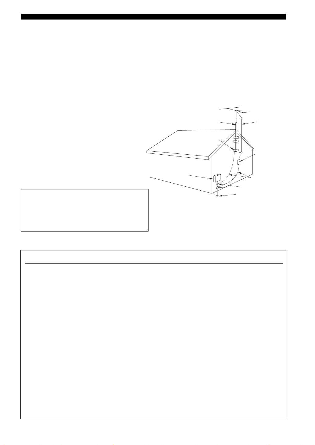
EXAMPLE OF ANTENNA GROUNDING
ANTENNA
LEAD IN
WIRE
ANTENNA
DISCHARGE UNIT
(NEC SECTION 810–20)
GROUNDING CONDUCTORS
(NEC SECTION 810–21)
GROUND CLAMPS
ELECTRIC
SERVICE
EQUIPMENT
NEC – NATIONAL ELECTRICAL CODE
MAST
GROUND
CLAMP
POWER SERVICE GROUNDING
ELECTRODE SYSTEM
(NEC ART 250. PART H)
FCC INFORMATION (for US customers)
1 IMPORTANT NOTICE: DO NOT MODIFY THIS
UNIT!
This product, when installed as indicated in the
instructions contained in this manual, meets FCC
requirements. Modifications not expressly approved by
Yamaha may void your authority, granted by the FCC, to
use the product.
2 IMPORTANT: When connecting this product to
accessories and/or another product use only high quality
shielded cables. Cable/s supplied with this product MUST
be used. Follow all installation instructions. Failure to
follow instructions could void your FCC authorization to
use this product in the USA.
3 NOTE: This product has been tested and found to comply
with the requirements listed in FCC Regulations, Part 15
for Class “B” digital devices. Compliance with these
requirements provides a reasonable level of assurance that
your use of this product in a residential environment will
not result in harmful interference with other electronic
devices.
This equipment generates/uses radio frequencies and, if
not installed and used according to the instructions found
in the users manual, may cause interference harmful to the
operation of other electronic devices.
Compliance with FCC regulations does not guarantee that
interference will not occur in all installations. If this
product is found to be the source of interference, which
can be determined by turning the unit “OFF” and “ON”,
please try to eliminate the problem by using one of the
following measures:
Relocate either this product or the device that is being
affected by the interference.
Utilize power outlets that are on different branch (circuit
breaker or fuse) circuits or install AC line filter/s.
In the case of radio or TV interference, relocate/reorient
the antenna. If the antenna lead-in is 300 ohm ribbon lead,
change the lead-in to coaxial type cable.
If these corrective measures do not produce satisfactory
results, please contact the local retailer authorized to
distribute this type of product. If you can not locate the
appropriate retailer, please contact Yamaha Electronics
Corp., U.S.A. 6660 Orangethorpe Ave., Buena Park, CA
90620.
The above statements apply ONLY to those products
distributed by Yamaha Corporation of America or its
subsidiaries.
Caution-ii En
Page 4

CAUTION: READ THIS BEFORE OPERATING YOUR UNIT.
Caution: Read this before operating your unit.
1 To assure the finest performance, please read this manual
carefully. Keep it in a safe place for future reference.
2 Install this sound system in a well ventilated, cool, dry, clean
place – away from direct sunlight, heat sources, vibration,
dust, moisture, and/or cold. Allow ventilation space of at least
30 cm on the top, 20 cm on the left and right, and 20 cm on
the back of this unit.
3 Locate this unit away from other electrical appliances, motors,
or transformers to avoid humming sounds.
4 Do not expose this unit to sudden temperature changes from
cold to hot, and do not locate this unit in a environment with
high humidity (i.e. a room with a humidifier) to prevent
condensation inside this unit, which may cause an electrical
shock, fire, damage to this unit, and/or personal injury.
5 Avoid installing this unit where foreign object may fall onto
this unit and/or this unit may be exposed to liquid dripping or
splashing. On the top of this unit, do not place:
– other components, as they may cause damage and/or
discoloration on the surface of this unit.
– burning objects (i.e. candles), as they may cause fire,
damage to this unit, and/or personal injury.
– containers with liquid in them, as they may fall and liquid
may cause electrical shock to the user and/or damage to
this unit.
6 Do not cover this unit with a newspaper, tablecloth, curtain,
etc. in order not to obstruct heat radiation. If the temperature
inside this unit rises, it may cause fire, damage to this unit,
and/or personal injury.
7 Do not plug in this unit to a wall outlet until all connections
are complete.
8 Do not operate this unit upside-down. It may overheat,
possibly causing damage.
9 Do not use force on switches, knobs and/or cords.
10 When disconnecting the power cable from the wall outlet,
grasp the plug; do not pull the cord.
11 Do not clean this unit with chemical solvents; this might
damage the finish. Use a clean, dry cloth.
12 Only voltage specified on this unit must be used. Using this
unit with a higher voltage than specified is dangerous and may
cause fire, damage to this unit, and/or personal injury. Yamaha
will not be held responsible for any damage resulting from use
of this unit with a voltage other than specified.
13 To prevent damage by lightning, keep the power cord and
outdoor antennas disconnected from a wall outlet or the unit
during a lightning storm.
14 Do not attempt to modify or fix this unit. Contact qualified
Yamaha service personnel when any service is needed. The
cabinet should never be opened for any reasons.
15 When not planning to use this unit for long periods of time
(i.e. vacation), disconnect the AC power plug from the wall
outlet.
16 Install this unit near the AC outlet and where the AC power
plug can be reached easily.
17 Be sure to read the “Troubleshooting” section on common
operating errors before concluding that this unit is faulty.
18 Before moving this unit, press CSYSTEM OFF to set this
unit in the standby mode, and disconnect the AC power plug
from the wall outlet.
19 VOLTAGE SELECTOR (Asia and General models only)
The VOLTAGE SELECTOR on the rear panel of this unit
must be set for your local main voltage BEFORE plugging
into the AC wall outlet.
Voltages are 110–120/220–240 V AC, 50/60 Hz.
20 The batteries shall not be exposed to excessive heat such as
sunshine, fire or like.
21 Excessive sound pressure from earphones and headphones can
cause hearing loss.
WAR NING
TO REDUCE THE RISK OF FIRE OR ELECTRIC
SHOCK, DO NOT EXPOSE THIS UNIT TO RAIN
OR MOISTURE.
This unit is not disconnected from the AC power
source as long as it is connected to the wall outlet, even
if this unit itself is turned off by CSYSTEM OFF.
This state is called the standby mode. In this state, this
unit is designed to consume a very small quantity of
power.
FOR CANADIAN CUSTOMERS
To prevent electric shock, match wide blade of plug to
wide slot and fully insert.
This Class B digital apparatus complies with Canadian
ICES-003.
POUR LES CONSOMMATEURS CANADIENS
Pour éviter les chocs électriques, introduire la lame la
plus large de la fiche dans la borne correspondante de
la prise et pousser jusqu’au fond.
Cet appareil numérique de la classe B est conforme à
la norme NMB-003 du Canada.
IMPORTANT
Please record the serial number of this unit in the space
below.
MODEL:
Serial No.:
The serial number is located on the rear of the unit.
Retain this Owner’s Manual in a safe place for future
reference.
Caution-iii En
Page 5

Contents
INTRODUCTION
Features ................................................................... 2
Getting started ........................................................ 3
Quick start guide .................................................... 4
Preparation: Check the items ..................................... 4
Step 1: Set up your speakers ...................................... 5
Step 2: Connect your DVD player and other
components............................................................ 6
Step 3: Press SCENE 1 button................................... 7
What do you want to do with this unit? ..................... 8
PREPARATION
Connections ............................................................. 9
Rear panel .................................................................. 9
Placing speakers....................................................... 10
Connecting speakers ................................................ 11
Information on jacks and cable plugs ...................... 13
Information on HDMI™.......................................... 14
Audio and video signal flow.................................... 15
Connecting video components................................. 16
Connecting other components ................................. 17
Connecting audio components................................. 19
Connecting a Yamaha iPod™ universal dock or
Bluetooth™ adapter............................................. 20
Using REMOTE IN/OUT jacks............................... 20
Using the VIDEO AUX jacks on the front panel .... 21
Connecting the FM and AM antennas ..................... 21
Connecting the power cable..................................... 22
Setting the speaker impedance................................. 23
Turning on and off the power .................................. 23
Front panel display .................................................. 24
Optimizing the speaker setting
for your listening room .................................... 26
Using AUTO SETUP .............................................. 26
XM Satellite Radio tuning ....................................48
Connecting the XM Mini-Tuner Dock .................... 48
Activating XM Satellite Radio ................................ 49
Basic XM Satellite Radio operations....................... 49
Setting XM Satellite Radio preset channels ............ 51
Displaying the XM Satellite Radio information...... 52
SIRIUS Satellite Radio™ tuning .........................53
Connecting the SiriusConnect™ tuner .................... 53
Activating SIRIUS Satellite Radio™ subscription.. 54
Basic SIRIUS Satellite Radio™ operations ............ 54
Setting the SIRIUS Satellite Radio™ preset
channels ............................................................... 56
Setting the Parental Lock......................................... 56
Displaying the SIRIUS Satellite Radio™
information .......................................................... 58
Using iPod™ ..........................................................59
Controlling iPod™................................................... 59
Using Bluetooth™ components ............................61
Pairing the Bluetooth™ adapter and your Bluetooth™
component ........................................................... 61
Playback of the Bluetooth™ component ................. 61
Recording ...............................................................62
ADVANCED OPERATION
SET MENU ............................................................ 63
Using SET MENU................................................... 64
1 SOUND MENU.................................................... 65
2 INPUT MENU...................................................... 71
3 OPTION MENU................................................... 73
Remote control features........................................76
Controlling this unit, a TV, or other components.... 76
Setting remote control codes ................................... 78
Using multi-zone configuration............................79
Connecting Zone 2................................................... 79
Controlling Zone 2................................................... 80
Advanced setup......................................................82
PREPARATIONINTRODUCTION
OPERATION
BASIC
OPERATION
ADVANCED
BASIC OPERATION
Selecting the SCENE templates........................... 30
Selecting the desired SCENE template.................... 30
Creating your original SCENE templates ................ 33
Using remote control on the SCENE feature........... 34
Playback ................................................................ 35
Basic operations....................................................... 35
Selecting audio input jacks
(AUDIO SELECT).............................................. 36
Selecting the MULTI CH INPUT component ......... 36
Displaying the current status of this unit on a video
monitor ................................................................ 37
Using your headphones............................................ 37
Muting the audio output........................................... 37
Playing video sources in the background of an audio
source................................................................... 38
Displaying the input source information ................. 38
Using the sleep timer ............................................... 39
Sound field programs ........................................... 40
Sound field program descriptions ............................ 40
Using audio features ............................................. 43
Enjoying high quality sound.................................... 43
Adjusting the tonal quality....................................... 43
Adjusting the speaker level...................................... 43
Selecting the night listening mode........................... 44
FM/AM tuning ...................................................... 45
Automatic tuning ..................................................... 45
Manual tuning.......................................................... 45
Automatic preset tuning........................................... 46
Manual preset tuning ............................................... 46
Selecting preset stations........................................... 47
Exchanging preset station ........................................ 47
ADDITIONAL INFORMATION
Troubleshooting.....................................................84
Glossary..................................................................94
Specifications .........................................................97
Index .......................................................................98
APPENDIX
(at the end of this manual)
Front panel................................................................i
Remote control ....................................................... ii
List of remote control codes ................................. iii
About this manual
• y indicates a tip for your operation.
• Some operations can be performed by using either the buttons on the
front panel or the ones on the remote control. In case the button
names differ between the front panel and the remote control, the
button name on the remote control is given in parentheses.
• This manual is printed prior to production. Design and specifications
are subject to change in part as a result of improvements, etc. In case
of differences between the manual and product, the product has
priority.
•“MSPEAKERS” or “4DVD” (example) indicates the name of the
parts on the front panel or the remote control. Refer to the attached
sheet or the pages at the end of this manual for the information about
each position of the parts.
• The symbol “☞ ” with page number(s) indicates the corresponding
reference page(s).
INFORMATION
ADDITIONAL
APPENDIX
English
1 En
Page 6

Features
Features
Built-in 7-channel power amplifier
◆ Minimum RMS output power
[U.S.A. and Canada models]
(1 kHz, 0.9% THD, 8 Ω)
90 W/ch
[Other models]
(1 kHz, 0.9% THD, 6 Ω)
90 W/ch
SCENE select function
◆ Preset SCENE templates for various situations
◆ SCENE template customizing capability
Decoders and DSP circuits
◆ Proprietary Yamaha technology for the creation of multichannel surround sound
◆ Compressed Music Enhancer mode
◆ Dolby Digital/Dolby Digital EX decoder
◆ DTS/DTS-ES Matrix, Discrete, DTS Neo:6,
DTS 96/24 decoder
◆ Dolby Pro Logic/Dolby Pro Logic II/Dolby Pro Logic IIx
decoder
◆ Neural Surround decoder
(U.S.A. and Canada models only)
◆ Virtual CINEMA DSP
◆ SILENT CINEMA
™
Radio tuners
◆ FM/AM tuning capability
◆ XM Satellite Radio tuning capability (using XM Mini-Tuner
and Home Dock, sold separately)
◆ SIRIUS Satellite Radio™ tuning capability (using SIRIUS
Connect tuner, sold separately)
HDMI (High-Definition Multimedia Interface)
◆ HDMI interface for standard, enhanced or high-definition
video (includes 1080p video signal transmission) as well as
multi-channel digital audio
DOCK terminal
◆ DOCK terminal to connect a Yamaha iPod universal dock
(such as YDS-10, sold separately) or Bluetooth adapter (such
as YBA-10, sold separately).
Other features
◆ YPAO (Yamaha Parametric Room Acoustic Optimizer) for
automatic speaker setup
◆ 192-kHz/24-bit D/A converter
◆ DIRECT mode for high quality sound for all sources
◆ 6 additional input jacks for discrete multi-channel input
◆ OSD (on-screen display) menus that allow you to optimize
this unit to suit your individual audiovisual system
◆ Component video input/output capability
(3 COMPONENT VIDEO INs and 1 MONITOR OUT)
◆ S-video signal input/output capability
◆ Optical and coaxial digital audio signal jacks
◆ Sleep timer
◆ Cinema and music night listening modes
◆ iPod controlling capability
◆ Remote control with preset remote control codes
◆ Zone 2 custom installation facility
◆ Bi-amplification connection capability
Manufactured under license from Dolby Laboratories.
“Dolby”, “Pro Logic”, and the double-D symbol are trademarks
of Dolby Laboratories.
“SILENT CINEMA” is a trademark of YAMAHA
CORPORATION.
iPod™
“iPod” is a trademark of Apple, Inc., registered in the U.S. and
other countries.
Bluetooth™
Bluetooth is a registered trademark of the Bluetooth SIG and is
used by Yamaha in accordance with a license agreement.
“HDMI”, the “HDMI” logo and “High-Definition Multimedia
Interface” are trademarks or registered trademarks of HDMI
Licensing LLC.
2 En
DTS-ES | NEO:6 | 96/24. Product “DTS” and “DTS-ES | NEO:6”
are registered trademarks of DTS, Inc.
“96/24” is a trademark of DTS, Inc.
The XM name and related logos are registered trademarks of XM
Satellite Radio Inc.
Neural Surround
by Neural Audio Corporation.
©2006 SIRIUS Satellite Radio Inc. “SIRIUS”, “Sirius Connect”,
the SIRIUS dog logo, channel names and logos are trademarks of
SIRIUS Satellite Radio Inc.
™
name and related logos are trademarks owned
Page 7
Getting started
Getting started
■ Supplied accessories
Check that you received all of the following parts.
❏ Remote control
❏ Batteries (2) (AAA, R03, UM-4)
❏ Optimizer microphone
❏ AM loop antenna
❏ Indoor FM antenna
■ VOLTAGE SELECTOR
(Asia and General models only)
Caution
The VOLTAGE SELECTOR on the rear panel of this
unit must be set for your local voltage BEFORE
plugging the power cable into the AC wall outlet.
Improper setting of the VOLTAGE SELECTOR may
cause damage to this unit and create a potential fire
hazard.
Rotate the VOLTAGE SELECTOR clockwise or
counterclockwise to the correct position using a
straight slot screwdriver.
Voltages are as follows:
Asia model ................... 220/230–240 V AC, 50/60 Hz
General model
...................... 110/120/220/230–240 V AC, 50/60 Hz
VOLTAGE
SELECTOR
230240V
Voltage indication
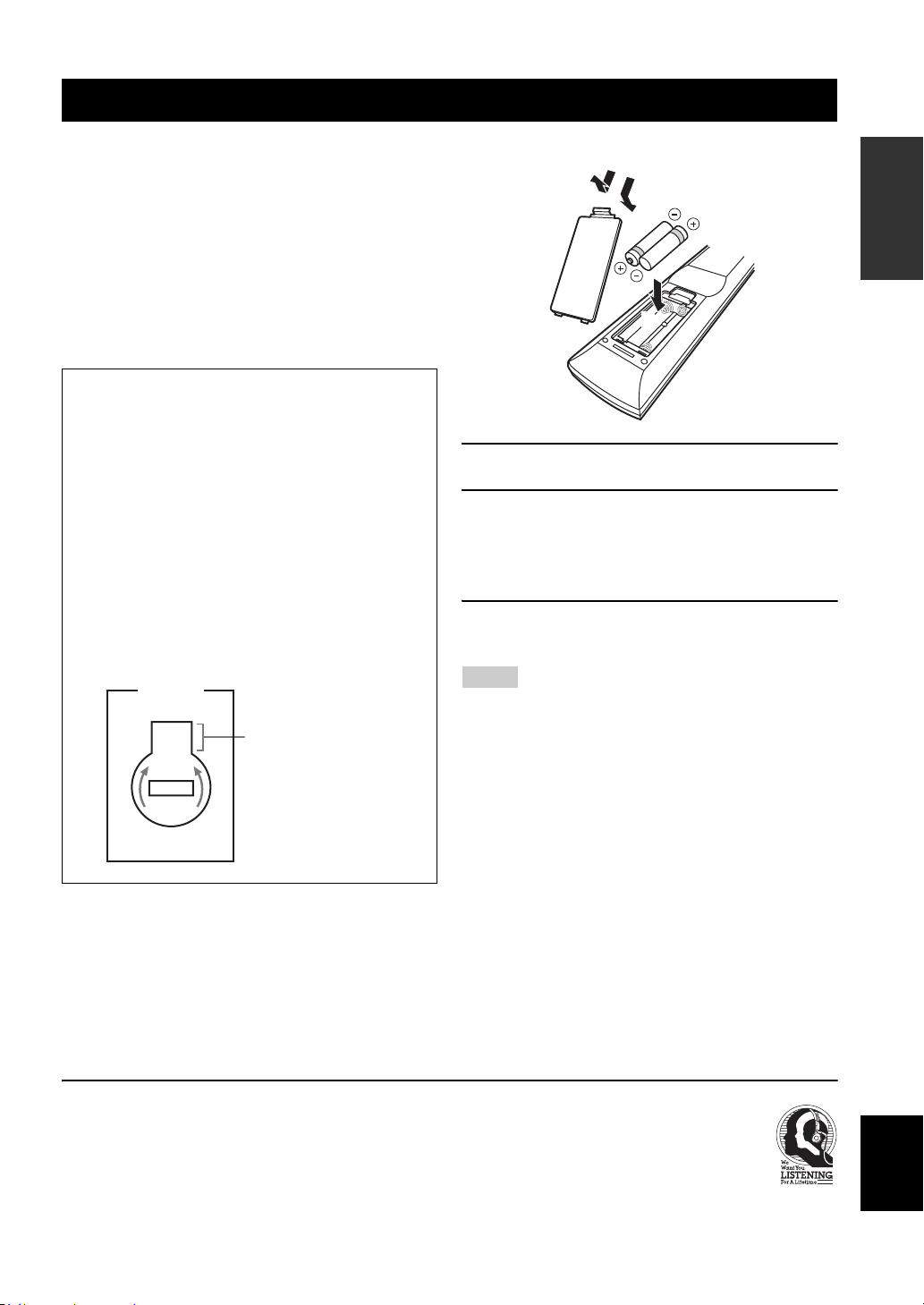
■ Installing batteries in the remote control
1
3
2
1 Take off the battery compartment cover.
2 Insert the two supplied batteries
(AAA, R03, UM-4) according to the polarity
markings (+ and –) on the inside of the
battery compartment.
3 Snap the battery compartment cover back
into place.
Notes
• Change all of the batteries if you notice that the operation range
of the remote control decreases.
• Do not use an old battery and a new one together.
• Do not use different types of batteries (such as alkaline and
manganese batteries) together. Read the packaging carefully as
these different types of batteries may have the same shape and
color.
• If the batteries have leaked, dispose of them immediately. Avoid
touching the leaked material or letting it come into contact with
clothing, etc. Clean the battery compartment thoroughly before
installing new batteries.
• Do not throw away batteries with general house waste; dispose
of them correctly in accordance with your local regulations.
• If the remote control is without batteries for more than 2
minutes, or if exhausted batteries remain in the remote control,
the contents of the memory may be cleared. When the memory
is cleared, insert new batteries and set up the remote control
code.
INTRODUCTION
We Want You Listening For A Lifetime
Yamaha and the Electronic Industries Association’s Consumer
Electronics Group want you to get the most out of your
equipment by playing it at a safe level. One that lets the sound
come through loud and clear without annoying blaring or
distortion – and, most importantly, without affecting your
sensitive hearing.
Since hearing damage from loud sounds is often
undetectable until it is too late, Yamaha and the
Electronic Industries Association’s Consumer
Electronics Group recommend you to avoid
prolonged exposure from excessive volume levels.
English
3 En
Page 8
Quick start guide
Quick start guide
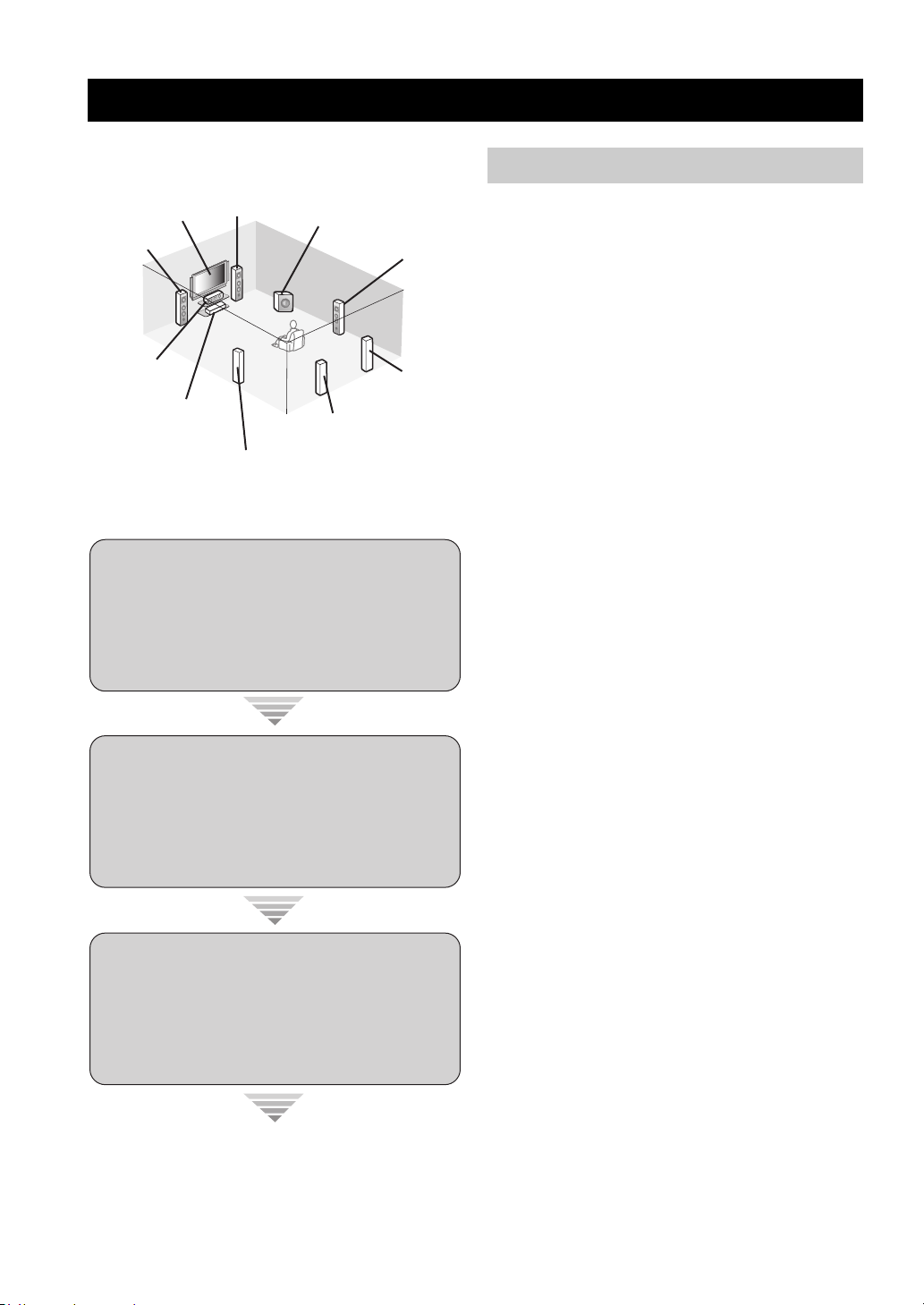
The following steps describe the easiest way to enjoy
DVD movie playback in your home theater.
Front right
Video monitor
Front left
speaker
Center speaker
DVD player
Step 1: Set up your speakers
Step 2: Connect your DVD player
speaker
Surround left
speaker
Subwoofer
Surround back left
speaker
Surround right
speaker
Surround back
right speaker
☞
P. 5
and other components
☞
P. 6
Preparation: Check the items
Prepare the following items.
❏ Speakers
❏ Front speaker .....................................x 2
❏ Center speaker ...................................x 1
❏ Surround speaker ..............................x 4
Select magnetically shielded speakers. The
minimum required speakers are two front speakers.
The priority of the requirement of other speakers is
as follows:
1. Two surround speakers
2. Center speaker
3. One (or two) surround back speaker(s)
❏ Active subwoofer ...................................x 1
Select an active subwoofer equipped with an RCA
input jack.
❏ Speaker cable .........................................x 7
❏ Subwoofer cable .....................................x 1
Select a monaural RCA cable.
❏ DVD player ..............................................x 1
Select DVD player equipped with coaxial digital
audio output jack and composite video output
jack.
❏ Video monitor ..........................................x 1
Select a TV monitor, video monitor or projector
equipped with a composite video input jack.
❏ Video cable .............................................x 2
Select an RCA composite video cable.
❏ Digital coaxial audio cable ....................x 1
Step 3: Press SCENE 1 button
Enjoy DVD playback!
4 En
☞
P. 7
Page 9
Step 1: Set up your speakers
Place your speakers in the room and connect them to this
unit.
SPEAKERS
COAXIAL
OPTICAL
DTV/CBL CD
DVD
1
2
VIDEO
OUT
OUT
DIGITAL INPUT
DVD
RPBYPRPB
P
A
MONITOR OUT
MONITOR
OUT
CD
3
XM SIRIUS DOCK
COMPONENT VIDEO ANTENNA
DTV/CBL
Y
B
DVR
C
MONITOR
OUT S VIDEOIN
DTV/CBL DVRDVD
OUT
L
CENTER
SUB
R
FRONT(6CH)
SB(8CH)
SUB
WOOFER
WOOFER
SUB
SURROUND
WOOFER
ZONE 2
OUTPUT
MULTI CH INPUTAUDIO
OUTPUT
OUT
DTV/CBL
OUT
DVD
IN1 IN2
HDMI
REMOTE
IN
OUT
+12V
VIDEO
15mA MAX.
TRIGGER
IN
DTV/CBL DVRDVD
OUT
L
R
IN
MD/
OUT
IN
CD-R
(REC)
(PLAY)
DTV/CBL DVRDVD
1 Place your speakers and subwoofer in the
room.
SPEAKERS
AM
SURROUND BACK/BI-AMP
SURROUND BACK/BI-AMP
LR
SURROUND
LR
GND
FM
75
UNBAL.
SURROUND
LR
LR
SINGLE
SINGLE
LR
LR
FRONT B
FRONT ACENTER
FRONT B
FRONT ACENTER
AC OUTLETS
SWITCHED
LR
LR
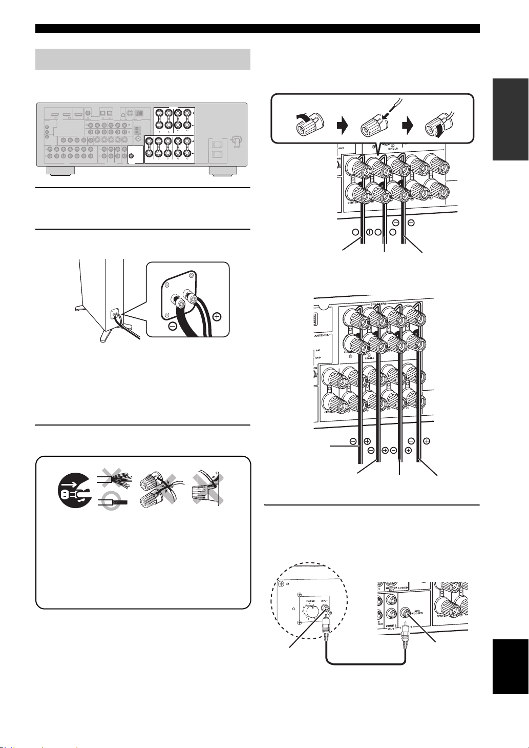
Quick start guide
Be sure to connect the left channel (L), right channel
(R), “+” (red) and “–” (black) properly.
Front and center speakers
Loosen Insert Tighten
INTRODUCTION
2 Connect speaker cables to each speaker.
Cables are colored or shaped differently, perhaps with
a stripe, groove or ridge. Connect the striped
(grooved, etc.) cable to the “+” (red) terminals of
your speaker. Connect the plain cable to the “–”
(black) terminals.
3 Connect each speaker cable to the
corresponding speaker terminal of this unit.
12 3 4
1 Make sure that this unit and the subwoofer are
unplugged from the AC wall outlets.
2 Twist the exposed wires of the speaker cables
together to prevent short circuits.
3 Do not let the bare speaker wires touch each other.
4 Do not let the bare speaker wires touch any metal
part of this unit.
To the center
speaker
To the front
right speaker
To the front
left speaker
Surround and surround back speakers
To the surround
back right
speaker
To the surround
back left speaker
To the surround
right speaker
To the surround
left speaker
4 Connect the subwoofer cable to the input
jack of the subwoofer and the SUBWOOFER
OUTPUT jack of this unit.
Subwoofer
AV receiver
Input jack
Subwoofer cable
SUBWOOFER
OUTPUT jack
English
5 En
Page 10
Quick start guide
Step 2: Connect your DVD player
and other components
COAXIAL
COAXIAL
OPTICAL
OPTICAL
DTV/CBL CD
DVD
DTV/CBL CDDVD
1
2
3
2
3
1
DTV/CBL
OUT
DVD
IN1 IN2
HDMI
REMOTE
IN
OUT
+12V
VIDEO
VIDEO
15mA MAX.
TRIGGER
OUT
L
R
MD/
OUT
IN
CD-R
(REC)
(PLAY)
DIGITAL INPUT
DIGITAL INPUT
DVD
A
MONITOR OUT
VIDEO
VIDEO
MONITOR
MONITOR
OUT
IN
OUTIN
DTV/CBL DVRDVD
DTV/CBL DVRDVD
OUT
OUT
OUT
IN
DTV/CBL DVRDVD
CD
XM SIRIUS DOCK
COMPONENT VIDEO ANTENNA
RPBYPRPB
P
DTV/CBL
Y
MONITOR
MONITOR
OUT S VIDEOIN
OUT S VIDEOIN
DTV/CBL DVRDVD
DTV/CBL DVRDVD
OUT
OUT
L
CENTER
R
SUB
FRONT(6CH)
SURROUND
WOOFER
SB(8CH)
ZONE 2
MULTI CH INPUTAUDIO
OUT
B
DVR
C
SUB
WOOFER
OUTPUT
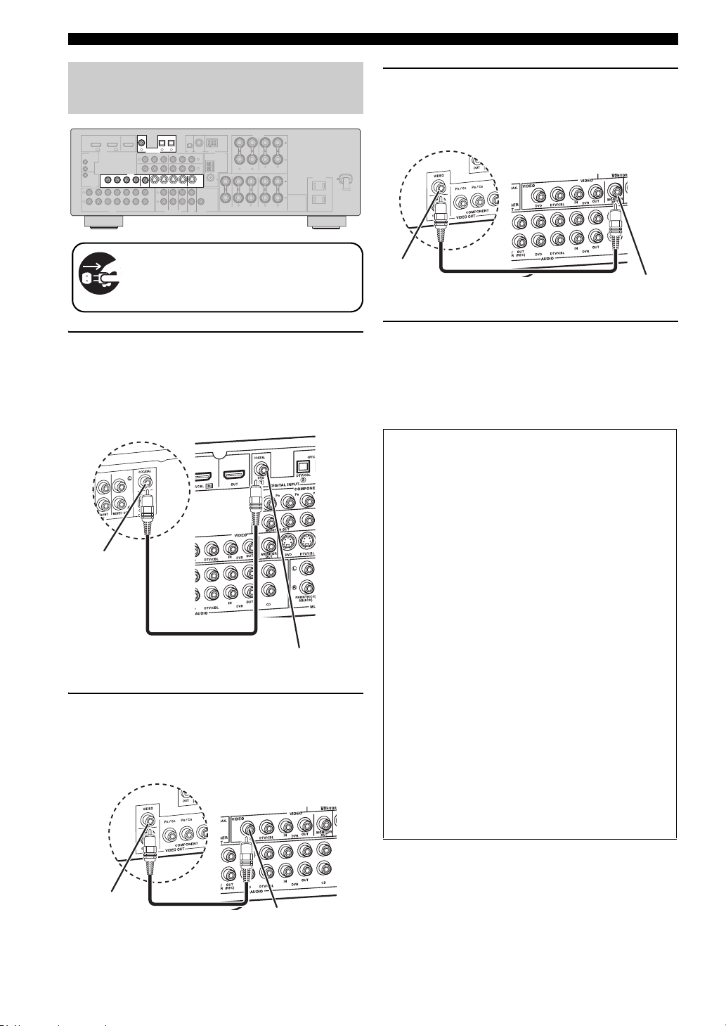
Make sure that this unit and the DVD
player are unplugged from the AC wall
outlets.
1 Connect the digital coaxial audio cable to the
digital coaxial audio output jack of your DVD
player and the DVD DIGITAL INPUT COAXIAL
jack of this unit.
DVD player
Digital coaxial
audio output jack
Digital coaxial audio
cable
2 Connect the video cable to the composite
video output jack of your DVD player and the
DVD VIDEO jack of this unit.
DVD player
SPEAKERS
AM
SURROUND BACK/BI-AMP
LR
GND
FM
75
UNBAL.
SURROUND
LR
SINGLE
LR
FRONT B
FRONT ACENTER
AC OUTLETS
SWITCHED
LR
AV receiver
DVD DIGITAL INPUT
COAXIAL jack
AV receiver
3 Connect the video cable to the video input
jack of your video monitor and the VIDEO
MONITOR OUT jack of this unit.
AV receiver
VIDEO MONITOR OUT
jack
Video input
jack
Video monitor
Video cable
4 Connect the power plug of this unit and other
components into the AC wall outlet.
y
This unit is equipped with AC OUTLET(S) for the power supply
of the other components (except Korea model). See page 22 for
details.
■ For further connections
• Using the other kind of speaker
combinations ☞ P. 11
• Connecting a video components ☞ P. 16
• Connecting a DVD player ☞ P. 17
• Connecting a DVD recorder ☞ P. 18
• Connecting a set-top boxes ☞ P. 18
• Connecting a CD player
and a CD recorder/ MD recorder ☞ P. 19
• Connecting a multi-format player
or an external decoder ☞ P. 19
• Connecting an Yamaha iPod/Bluetooth
dock ☞ P. 20
• Connecting the REMOTE IN/OUT jacks
☞ P. 20
• Using the VIDEO AUX jacks on the front
panel ☞ P. 21
• Connecting an FM/AM antenna ☞ P. 21
• Connecting the XM Mini-Tuner Dock
☞ P. 48
• Connecting the SIRIUS Connect tuner
☞ P. 53
Composite video
output jack
6 En
Video cable
DVD VIDEO jack
Page 11
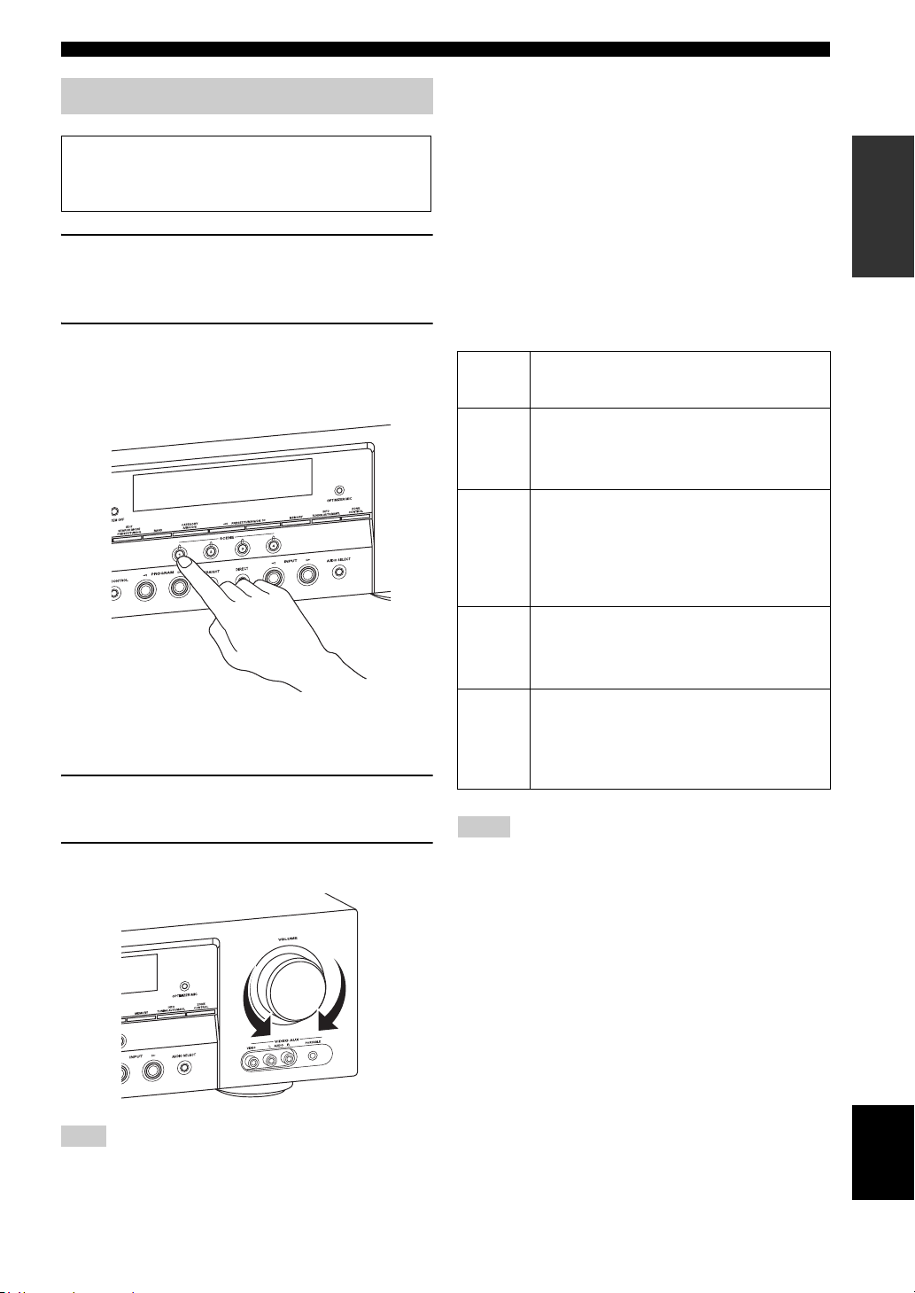
Step 3: Press SCENE 1 button
Check the type of the connected speakers.
If the speakers are 6 ohm speakers, set “SP IMP.” to
“6Ω MIN” before using this unit (see page 23).
1 Turn on the video monitor and then set the
input source selector of the video monitor to
this unit.
Quick start guide
■ About SCENE function
Just by pressing one SCENE button, you can turn on this
unit and recall your favorite input source and sound field
program according to the SCENE template that has been
assigned to the SCENE button. The SCENE templates are
built combinations of input sources and sound field
programs.
y
If you connect a Yamaha product that has capability of the
SCENE control signals, this unit can automatically activate the
component and start playback. Refer to the instruction manual of
the DVD player for further information.
INTRODUCTION
2 Press
T
SCENE 1.
This unit is turned on. “DVD Viewing” appears in the
front panel display, and this unit automatically
optimize own status for the DVD playback.
y
The indicator on the selected SCENE button lights up while
this unit is in the SCENE mode.
3 Start playback of the desired DVD on your
player.
4 Rotate
L
VOLUME to adjust the volume.
■ Using the other SCENE buttons
Default
SCENE
button
SCENE 1DVD Viewing
SCENE 2Disc Listening
SCENE
3
SCENE
4
Notes
*1
You must connect a cable TV or a satellite tuner to this unit in
advance. See page 18 for details.
*2
You need to connect the supplied FM and AM antennas to this
unit in advance. See page 21 for details.
*3
You must tune into the desired radio station. See pages 45 to 47
for the tuning information.
*4
To achieve the best possible reception, orient the connected
AM loop antenna, or adjust the position of the end of the
indoor FM antenna.
y
If you cannot find the desired situation, you can select and change
the assigned SCENE template for the SCENE buttons. See
page 30 for details.
The name of the SCENE template
and its description
– input source: DVD
– sound field program: STRAIGHT
For when you want to enjoy a DVD playback.
– input source: DVD
– sound field program: 7ch Stereo
For when you want to listen to a music disc from
the connected DVD player as the background
music for this room.
TV Viewing
– input source: DTV/CBL
– sound field program: STRAIGHT
For when you want to watch a TV program.
Radio Listening
– input source: TUNER
– sound field program: 7ch Enhancer
For when you want to listen to a music program
from the FM radio station.
*1
*2, *3, *4
Note
When you change the input source or sound field program, the
SCENE mode is deactivated, and the indicator on the selected
SCENE button turns off.
English
7 En
Page 12
Quick start guide
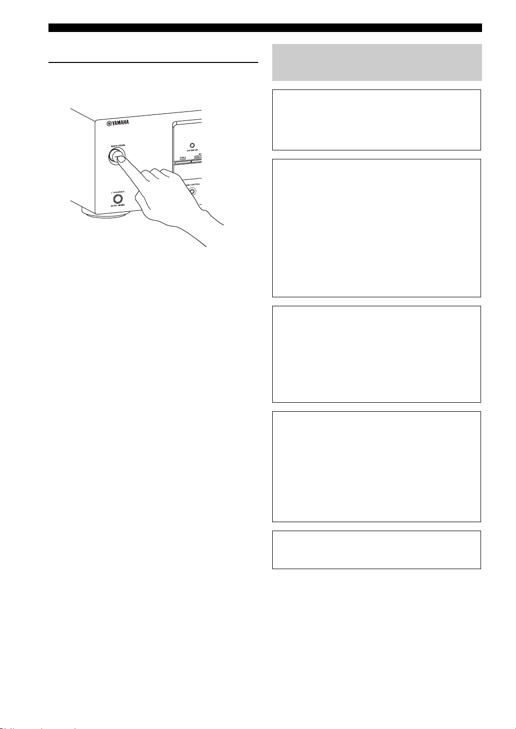
■ After using this unit...
Press AMAIN ZONE ON/OFF on the front
panel to set this unit to the standby mode.
This unit is set to the standby mode. In the standby mode,
this unit consumes a small amount of power in order to
receive infrared signals from the remote control. To turn
on this unit from the standby mode, press AMAIN ZONE
ON/OFF (or HPOWER). See page 23 for details.
What do you want to do with this unit?
■ Customizing the SCENE templates
• Using various SCENE templates ☞ P. 30
• Creating your original SCENE templates
☞ P. 33
■ Using various input sources
• Basic controls of this unit ☞ P. 35
• Enjoying FM/AM radio programs ☞ P. 45
• Enjoying XM Satellite Radio programs
☞ P. 48
• Enjoying SIRIUS Satellite Radio programs
☞ P. 53
• Using your iPod with this unit. ☞ P. 59
• Using your Bluetooth components
with this unit. ☞ P. 61
■ Using various sound features
• Using various sound field programs
☞ P. 40
• Using the direct mode for
the high quality sound ☞ P. 43
• Customizing the sound field programs
☞ P. 42
8 En
■ Adjusting the parameters of this unit
• Automatically optimizing the speaker
parameters for your listening room (AUTO
SETUP) ☞ P. 26
• Manually adjusting various parameters of
this unit ☞ P. 63
• Setting the remote control ☞ P. 76
• Adjusting the advanced parameters☞ P. 82
■ Additional features
Automatically turning off this unit ☞ P. 39
Page 13
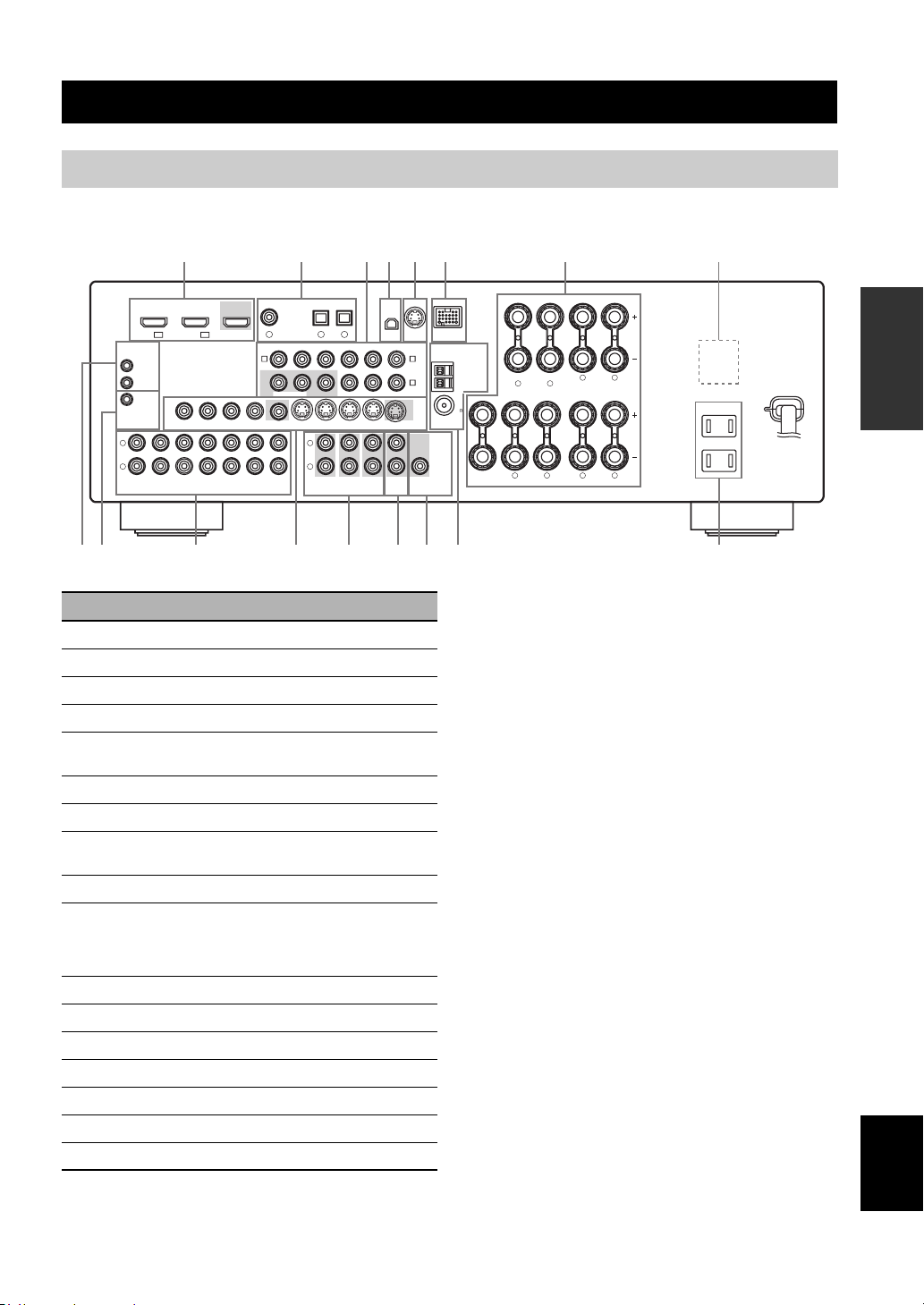
Rear panel
Connections
Connections
L
R
(PLAY)
REMOTE
IN
OUT
+12V
15mA MAX.
TRIGGER
IN
DVD
IN1 IN2
HDMI
VIDEO
OUT
MD/
OUT
CD-R
(REC)
1
DTV/CBL
OUT
VIDEO
IN
DTV/CBL DVRDVD
IN
DTV/CBL DVRDVD
2 43 5 6 7 8
COAXIAL
DVD
1
DVD
A
MONITOR
OUT
OUT
OPTICAL
DTV/CBL CD
2
DIGITAL INPUT
P
MONITOR OUT
OUT
CD
3
SURROUND
XM SIRIUS DOCK
MONITOR
OUT S VIDEOIN
CENTER
SUB
WOOFER
ZONE 2
OUT
OUT
COMPONENT VIDEO ANTENNA
RPB
YPRPBY
DTV/CBL DVRDVD
L
R
FRONT(6CH)
SB(8CH)
MULTI CH INPUTAUDIO
Name Page
1 HDMI jacks 14
2 DIGITAL INPUT jacks 13
3 COMPONENT VIDEO jacks 13
4 XM jack (U.S.A. and Canada models only) 48
5 SIRIUS jack
(U.S.A. and Canada models only)
6 DOCK terminal 20
7 Speaker terminals 11
8 VOLTAGE SELECTOR
(Asia and General models only)
9 REMOTE IN/OUT jacks 20
0
TRIGGER OUT jack
This is a control expansion jack for custom
installation.
A AUDIO jacks 13
B VIDEO jacks 13
C MULTI CH INPUT jacks 19
D ZONE 2 OUT jacks 79
E SUBWOOFER OUTPUT jack 11
F ANTENNA terminals 21
G AC OUTLET(S) 22
DTV/CBL
B
DVR
C
OUTPUT
WOOFER
SPEAKERS
AM
SURROUND BACK/BI-AMP
GND
FM
75
UNBAL.
SUB
LR
SINGLE
LR
FRONT ACENTER
SURROUND
FRONT B
LR
AC OUTLETS
SWITCHED
LR
GFB EDCA9 0
(U.S.A. model)
PREPARATION
53
3
—
English
9 En
Page 14
Connections
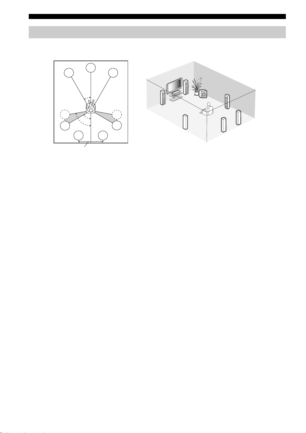
Placing speakers
The speaker layout below shows the speaker setting we recommend. You can use it to enjoy CINEMA DSP and multichannel audio sources.
FL
C
FR
FR
30˚
FL
SW
SR
C
SL
SL
30 cm (12 in) or more
80˚
SBL
60˚
SBR
SR
SR
SL
SBR
SBL
Front left and right speakers (FL and FR)
The front speakers are used for the main source sound plus effect sounds. Place these speakers at an equal distance from the
ideal listening position. The distance of each speaker from each side of the video monitor should be the same.
Center speaker (C)
The center speaker is for the center channel sounds (dialog, vocals, etc.). If for some reason it is not practical to use a
center speaker, you can do without it. Best results, however, are obtained with the full system.
Surround left and right speakers (SL and SR)
The surround speakers are used for effect and surround sounds.
Surround back left and right speakers (SBL and SBR)
The surround back speakers supplement the surround speakers and provide more realistic front-to-back transitions.
Subwoofer (SW)
The use of a subwoofer with a built-in amplifier, such as the Yamaha Active Servo Processing Subwoofer System, is
effective not only for reinforcing bass frequencies from any or all channels, but also for high fidelity sound reproduction
of the LFE (low-frequency effect) channel included in Dolby Digital and DTS sources. The position of the subwoofer is
not so critical, because low bass sounds are not highly directional. But it is better to place the subwoofer near the front
speakers. Turn it slightly toward the center of the room to reduce wall reflections.
10 En
Page 15
Connections
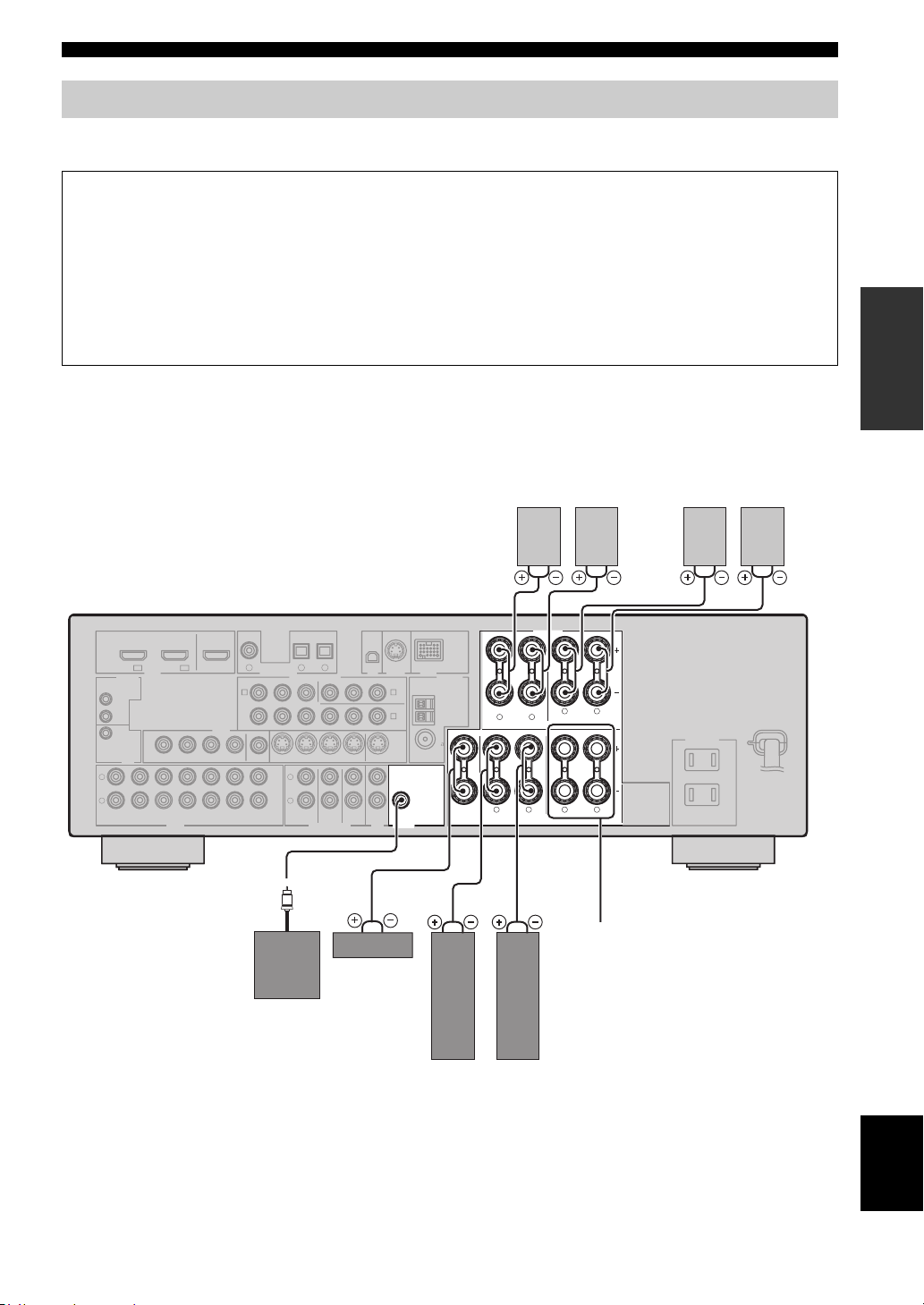
Connecting speakers
Be sure to connect the left channel (L), right channel (R), “+” (red) and “–” (black) properly. If the connections are faulty,
this unit cannot reproduce the input sources accurately.
Caution
• Before connecting the speakers, make sure that the AC power plug is disconnected from the AC wall outlet.
• Do not let the bare speaker wires touch each other or let them touch any metal part of this unit. This could damage
this unit and/or the speakers. If the speaker wires are short-circuited, “CHECK SP WIRES” appears in the front
panel display when you turn on this unit.
• Use the magnetically shielded speakers. If this type of speaker still creates interference with the monitor, place the
speakers away from the monitor.
• If you are to use 6 ohm speakers, be sure to set “SP IMP.” to “6Ω MIN” before using this unit. For details about the
speaker impedance setting, see page 23.
When you use single surround
back speaker, connect the
speaker to the left SURROUND
BACK terminal (SINGLE).
Surround back speakers
Right
Left
Surround speakers
Right
Left
PREPARATION
L
R
(PLAY)
OUT
+12V
15mA MAX.
IN
DVD
IN1 IN2
REMOTE
IN
TRIGGER
OUT
MD/
CD-R
(REC)
SURROUND BACK/BI-AMP
SINGLE
LR
FRONT ACENTER
SPEAKERS
LR
SURROUND
FRONT B
LR
AC OUTLET S
SWITCHED
LR
COAXIAL
DVD
DTV/CBL
HDMI
VIDEO
DTV/CBL DVRDVD
OUT
DTV/CBL DVRDVD
1
OUT
DVD
A
VIDEO
MONITOR
IN
OUT
OUT
IN
OPTICAL
DTV/CBL CD
2
DIGITAL INPUT
P
MONITOR OUT
OUT
CD
3
SURROUND
XM SIRIUS DOCK
MONITOR
OUT S VIDEOIN
CENTER
SUB
WOOFER
ZONE 2
OUT
OUT
COMPONENT VIDEO ANTENNA
RPB
YPRPBY
DTV/CBL DVRDVD
L
R
FRONT(6CH)
SB(8CH)
MULTI CH INPUTAUDIO
DTV/CBL
B
C
OUTPUT
AM
DVR
GND
FM
75
UNBAL.
SUB
WOOFER
FRONT B terminals
Connect the alternative front speaker system
Center
(FRONT B).
speaker
Subwoofer
Right
Left
Front speakers
(FRONT A)
English
11 En
Page 16
Connections
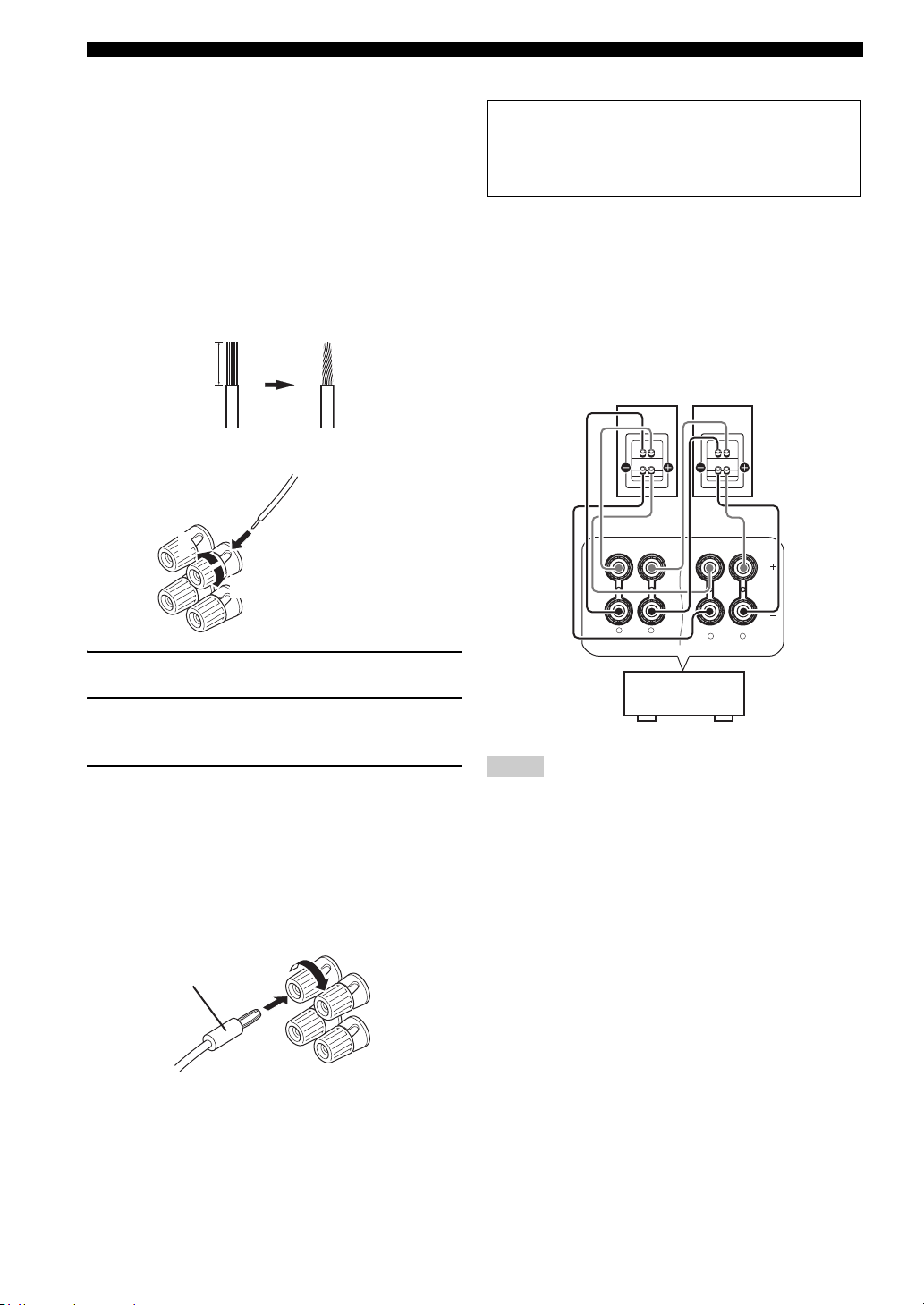
■ Before connecting to the SPEAKERS
terminal
A speaker cord is actually a pair of insulated cables
running side by side. Cables are colored or shaped
differently, perhaps with a stripe, groove or ridges.
Connect the striped (grooved, etc.) cable to the “+” (red)
terminals of this unit and your speaker. Connect the plain
cable to the “–” (black) terminals.
Remove approximately 10 mm (3/8”) of insulation
from the end of each speaker cable and then
twist the bare wires of the cable together to
prevent short circuits.
10 mm (3/8”)
■ Connecting to the FRONT A terminals
2
1
Red: positive (+)
Black: negative (–)
3
■ Using bi-amplification connections
Caution
Remove the shorting bars or bridges to separate the
LPF (low pass filter) and HPF (high pass filter)
crossovers.
This unit allows you to make bi-amplification connections
to one speaker system. Check if your speakers support biamplification.
To make the bi-amplification connections, use the FRONT
and SURROUND BACK terminals as shown below. To
activate the bi-amplification connections, set “BI-AMP”
to “ON” in “Advanced setup” (see page 82).
Front speakers
Right
Left
1 Loosen the knob.
2 Insert the bare end of the speaker wire into
the hole on the terminal.
3 Tighten the knob to secure the wire.
Connecting the banana plug
(except Europe, Russia, Korea, and Asia models)
The banana plug is a single-pole electrical connector
widely used to terminate speaker cables. First, tighten the
knob and then insert the banana plug connector into the
end of the corresponding terminal.
Banana plug
FRONT A
This unit
SINGLE
LR
SURROUND BACK/BI-AMP
LR
Notes
• When you make the conventional connection, make sure that
the shorting bars are put into the terminals appropriately. Refer
to the instruction manuals of the speakers for details.
• When you use bi-amplification connections, you can not use
surround back speakers.
12 En
Page 17
Connections
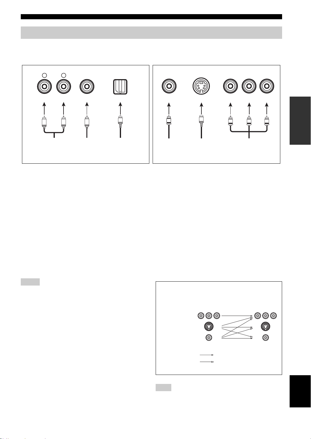
Information on jacks and cable plugs
Connect one of the type of the audio jack(s) and/or video jack(s) that your input components are equipped with.
Audio jacks and cable plugs Video jacks and cable plugs
AUDIO
L
L
Left and right
analog audio
cable plugs
R
(Red)(White) (Orange) (Yellow) (Red) (Blue) (Green)
R
DIGITAL AUDIO
COAXIAL
C
Coaxial
digital audio
cable plug
DIGITAL AUDIO
OPTICAL
O
Optical
digital
audio cable
plug
■ Audio jacks
This unit has three types of audio jacks. Connection
depends on the availability of audio jacks on your other
components.
AUDIO jacks
For conventional analog audio signals transmitted via left
and right analog audio cables. Connect red plugs to the
right jacks and white plugs to the left jacks.
DIGITAL AUDIO COAXIAL jacks
For digital audio signals transmitted via coaxial digital
audio cables.
DIGITAL AUDIO OPTICAL jacks
For digital audio signals transmitted via optical digital
audio cables.
Notes
• You can use the digital jacks to input PCM, Dolby Digital and
DTS bitstreams. Optical input jacks are compatible with digital
signals with up to 96 kHz of sampling frequency.
• This unit handles digital and analog signals independently. Thus
audio signals input at the digital jacks are not output at the
analog AUDIO OUT (REC) jacks.
VIDEO S VIDEO
V
Composite
video cable
plug
S
S-video
cable plug
COMPONENT VIDEO
P
R
P
B
PR
PB
Component
video cable
plugs
Y
Y
■ Video jacks
This unit has three types of video jacks. Connection
depends on the availability of input jacks on your video
monitor.
VIDEO jacks
For conventional composite video signals transmitted via
composite video cables.
S VIDEO jacks
For S-video signals, separated into the luminance (Y) and
chrominance (C) video signals transmitted on separate
wires of S-video cables.
COMPONENT VIDEO jacks
For component signals, separated into the luminance (Y)
and chrominance (P
separate wires of component video cables.
Video signal flow for MONITOR OUT
COMPONENT
VIDEO
S VIDEO
B, PR) video signals transmitted on
Input
PR PB Y PR PB Y
Output
(MONITOR OUT)
PREPARATION
VIDEO
Through
Video conversion ON
(see page 73)
Note
The OSD signal is not output at the DVR OUT (REC) jacks.
13 En
English
Page 18
Connections
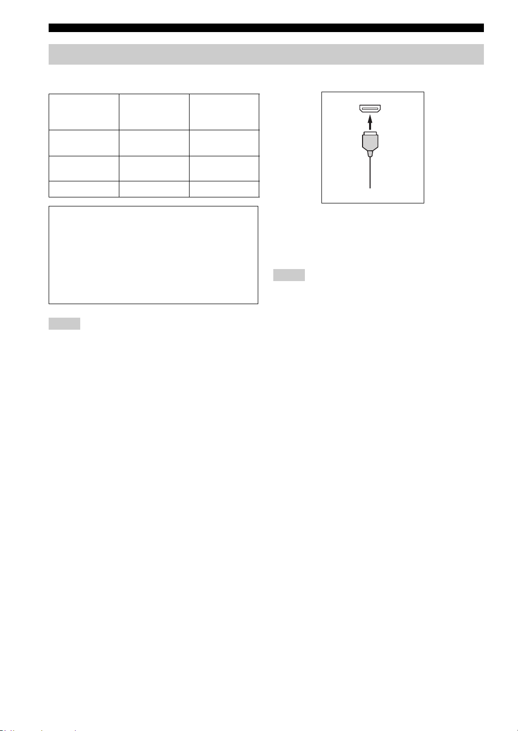
Information on HDMI™
■ HDMI compatibility with this unit
Audio signal
types
2ch Linear PCM 2ch, 32-192 kHz,
Multi-ch Linear
PCM
Bitstream Dolby Digital, DTS DVD-Video, etc.
Audio signal
formats
16/20/24 bit
8ch, 32-192 kHz,
16/20/24 bit
This unit’s HDMI interface is based on the following
standards:
• HDMI Version 1.2a (High-Definition Multimedia
Interface Specification Version 1.2a) licensed by
HDMI Licensing, LLC.
• HDCP (High-bandwidth Digital Content Protection
System) licensed by Digital Content Protection,
LLC.
Notes
• When CPPM copy-protected DVD audio is played back, video
and audio signals may not be output depending on the type of
the DVD player.
• This unit is not compatible with HDCP-incompatible HDMI or
DVI components.
• You can check the potential problem about the HDMI
connection (see page 38).
Compatible
HDMI
components
CD, DVD-Video,
DVD-Audio, etc.
DVD-Audio, etc.
■ HDMI jack and cable plug
HDMI
HDMI cable plug
y
• We recommend using an HDMI cable shorter than 5 meters (16
feet) with the HDMI logo printed on it.
• Use a conversion cable (HDMI jack
this unit to other DVI components.
Notes
• Do not disconnect or connect the cable or turn off the power of
the HDMI components connected to the HDMI OUT jack of
this unit while data is being transferred. Doing so may disrupt
playback or cause noise.
• Audio signals input at input jacks other than the HDMI IN DVD
or HDMI IN DTV/CBL jack of this unit cannot be digitally
output at the HDMI OUT jack.
• If you turn off the power of the video monitor connected to the
HDMI OUT jack via a DVI connection, this unit may fail to
establish the connection to the component.
↔ DVI-D jack) to connect
14 En
Page 19
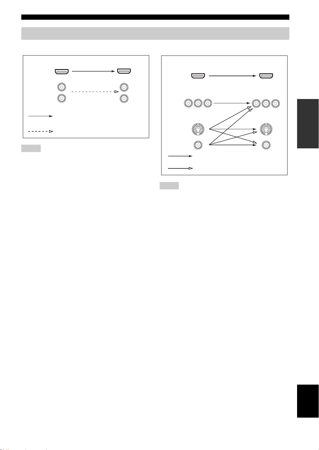
Audio and video signal flow
Connections
■ Audio signal flow
OutputInput
HDMI
AUDI O
Digital output
Analog output
Notes
• 2-channel as well as multi-channel PCM, Dolby Digital and
DTS signals input at the HDMI IN DVD or HDMI IN DTV/
CBL jack can be output at the HDMI OUT jack only when
“SUPPORT AUDIO” is set to “Other” (see page 70).
• Audio signals input at the HDMI IN jacks are not output at the
AUDIO output jacks.
■ Video signal flow
OutputInput
HDMI
COMPONENT
VIDEO
S VIDEO
VIDEO
Through
Video conversion ON (see page 73)
Notes
• When the all video signals are input at the HDMI,
COMPONENT VIDEO, S VIDEO and VIDEO jacks, the
priority order of the input signals is as follows:
1. HDMI
2. COMPONENT VIDEO
3. S VIDEO
4. VIDEO
When some digital video signals are input at the HDMI IN
DVD or HDMI IN DTV/CBL jack, the video conversion
function does not work.
• Digital video signals input at the HDMI IN DVD or HDMI IN
DTV/CBL jack cannot be output from analog video output
jacks.
PREPARATION
15 En
English
Page 20
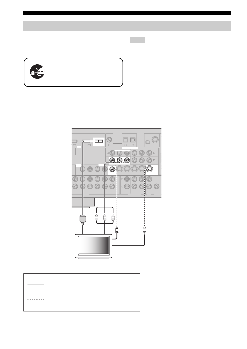
Connections
O
Connecting video components
Connect your TV (or projector) to the HDMI OUT jack,
the COMPONENT VIDEO MONITOR OUT jacks, the S
VIDEO MONITOR OUT jack or the VIDEO MONITOR
OUT jack of this unit.
Make sure that this unit and other
components are unplugged from the
AC wall outlets.
y
You can choose to play back HDMI audio signals on this unit or
on another HDMI component connected to the HDMI OUT jack
of this unit. Use the “SUPPORT AUDIO” parameter in “SOUND
MENU” to select the component to play back HDMI audio
signals (see page 70).
Notes
• Some video monitors connected to this unit via a DVI
connection fail to recognize the HDMI audio/video signals
being input if they are in the standby mode. In this case, the
HDMI indicator flashes irregularly.
• When you connect your TV monitor or projector via HDMI
connection, the OSD does not appear. In such cases, connect the
TV monitor or projector via component, S-video or video
connection.
• Connect the input source components to the HDMI IN DVD or
HDMI IN DTV/CBL jack to display the video images on the
video monitor connected to the HDMI OUT jack.
D
IN1 IN2
TE
VIDEO
AX.
ER
T
/ -ROUT
(REC)
HDMI in
HDMI
HDMI
VIDEO
DTV/CBL
OUT
OUT
VIDEO
VIDEO
IN
DTV/CBL DVRDVD
DTV/CBL DVRDVD
PR PB
Component
video in
TV (or projector)
COAXIAL
DVD
1
DVD
A
MONITOR OUT
MONITOR OUT
MONITOR
MONITOR
OUT
OUT
OUT
OUTIN
CD
Y
DIGITAL INPUT
RPB
P
RPB
P
V
OPTICAL
DTV/CBL CD
2
3
COMPONENT VIDEO
COMPONENT VIDEO
Y
YPRPBY
DTV/CBL DVRDVD
L
R
FRONT(6CH)
SURROUND
SB(8CH)
MULTI CH INPUTAUDIO
CENTER
SUB
WOOFER
OUT S VIDEOIN
XM SIRIUS
MONITOR
MONITOR
ZONE 2
S
DTV/CBL
B
DVR
C
S VIDEO
OUT
OUT
W
OUTPUT
OUT
Video in
S-video in
16 En
indicates recommended connections
indicates alternative connections
(One for the video connection,
and one for the audio connection)
Page 21
Connecting other components
O
Make sure that this unit and other
components are unplugged from the
AC wall outlets.
Notes
• When “VIDEO CONV.” is set to “OFF” (see page 73), be sure
to make the same type of video connections as those made for
your TV (see page 16). For example, if you connected your TV
to the VIDEO MONITOR OUT jack of this unit, connect your
other components to the VIDEO jacks.
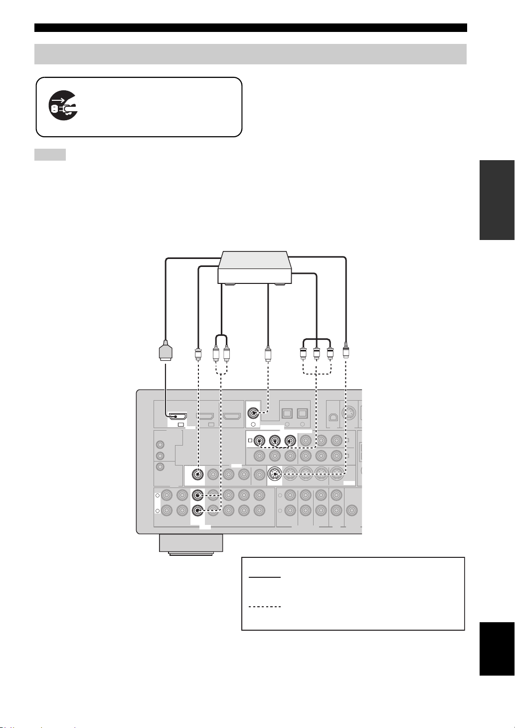
■ Connecting a DVD player
DVD player
HDMI out
Connections
• When “VIDEO CONV.” is set to “ON” (see page 73), the
converted video signals are output only at the MONITOR OUT
jacks. To record a source, make the same type of video
connections between each component.
• To make a digital connection to a component other than the
default component assigned to DIGITAL INPUT jack, select
the corresponding setting for “OPTICAL IN” or “COAXIAL
IN” in “INPUT ASSIGNMENT” (see page 71).
• If you connect your DVD player to both the DIGITAL INPUT
(OPTICAL) and the DIGITAL INPUT (COAXIAL) jacks,
priority is given to the signals input at the DIGITAL INPUT
(COAXIAL) jack.
S-video out
PREPARATION
Video out
V
DTV/CBL
DVD
IN1 IN2
DVD
IN1
HDMI
HDMI DIGITAL INPUT
REMOTE
IN
OUT
+12V
VIDEO
VIDEO
15mA MAX.
TRIGGER
OUT
L
L
R
R
MD/
IN
CD-R
(PLAY)
DTV/CBL DVRDVD
DVD DVD
OUT
(REC)
DTV/CBL DVRDVD
DVD
AUDIO
Component
video out
Audio out
Coaxial out
OUT S VIDEOIN
CENTER
SUB
WOOFER
S
XM SIRIUS
DTV/CBL
MONITOR
S VIDEO
OUT
ZONE 2
OUT
B
DVR
C
OUTPUT
W
LR
OUT
VIDEO
VIDEO
IN
IN
C
COAXIAL
COAXIAL
DVD
DVD
1
1
DIGITAL INPUT
DVD
DVD
RPB
P
RPB
P
A
A
MONITOR OUT
MONITOR
OUT
OUT
OUT
CD
PR PB Y
OPTICAL
DTV/CBL CD
2
3
COMPONENT VIDEO
COMPONENT VIDEO
YPRPBY
Y
DTV/CBL DVRDVD
L
R
FRONT(6CH)
SURROUND
SB(8CH)
MULTI CH INPUTAUDIO
indicates recommended connections
indicates alternative connections
(One for the video connection,
and one for the audio connection)
English
17 En
Page 22
Connections
O
DTV/CBL CD
DVD
O
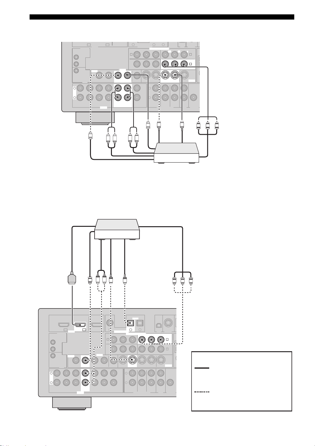
■ Connecting a DVD recorder, PVR or VCR
DTV/CBL
DVD
IN1 IN2
HDMI
REMOTE
IN
OUT
+12V
VIDEO
VIDEO
15mA MAX.
TRIGGER
OUT
L
L
R
R
MD/
IN
CD-R
(PLAY)
DTV/CBL DVRDVD
OUT
(REC)
DTV/CBL DVRDVD
AUDIO
Audio out
V
R
■ Connecting a set-top box
Satellite receiver, cable TV
receiver or HDTV decoder
DIGITAL INPUT
P
RPB
MONITOR OUT
OUT
CD
L
COMPONENT VIDEO
COMPONENT VIDEO
L
R
FRONT(6CH)
V
Video in
SB(8CH)
2
3
YPRPBY
RPB
P
DTV/CBL DVRDVD
DVR
SURROUND
MULTI CH INPUTAUDIO
S-video out
S
OUT S VIDEOIN
OUT S VIDEOIN
CENTER
SUB
WOOFER
XM SIRIUS
DTV/CBL
Y
MONITOR
OUT
ZONE 2
OUT
S-video in
S
B
DVR
DVR
C
C
W
OUTPUT
PR PB Y
1
OUT
DVD
A
VIDEO
VIDEO
MONITOR
OUT
IN
OUTIN
DVR
IN
OUT
IN
OUT
DVR
Audio in
R
L
Component video out
Video out
DVD recorder,
PVR or VCR
HDMI out Component video out
Video out
DTV/CBL
DTV/CBL
L
L
R
R
(PLAY)
REMOTE
IN
OUT
+12V
15mA MAX.
TRIGGER
IN
DVD
OUT
MD/
CD-R
IN1 IN2
(REC)
IN2
HDMI DIGITAL INPUT
HDMI
VIDEO
VIDEO
DTV/CBL DTV/CBL
DTV/CBL DVRDVD
OUT
DTV/CBL
DTV/CBL DVRDVD
AUDIO
Audio out
S-video out
Optical out
L R
V
OUT
VIDEO
VIDEO
IN
IN
COAXIAL
DVD
1
DVD
A
OUT
OUT
S
MONITOR OUT
MONITOR
OUT
CD
DIGITAL INPUT
RPB
P
O
OPTICAL
OPTICAL
DTV/CBL CD
DTV/CBL
2
2
COMPONENT VIDEO
COMPONENT VIDEO
YPRPBY
DTV/CBL DVRDVD
L
R
FRONT(6CH)
SB(8CH)
MULTI CH INPUTAUDIO
3
SURROUND
RPB
P
OUT S VIDEOIN
CENTER
SUB
WOOFER
XM SIRIUS
DTV/CBL
DTV/CBL
Y
MONITOR
S VIDEO
OUT
ZONE 2
OUT
PR PB Y
B
B
DVR
C
OUTPUT
indicates recommended
connections
W
indicates alternative
connections
(One for the video connection,
and one for the audio
connection)
18 En
Page 23
Connecting audio components
R
W
U
Connect the audio components as follows.
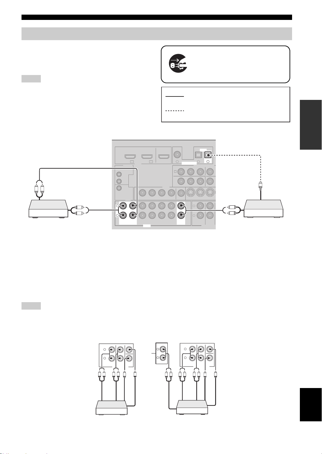
■ Connecting a CD player and a CD
recorder/MD recorder
Notes
• When you connect your CD player via analog and digital
connection, priority is given to the signal input at the DIGITAL
INPUT jack.
• To make a digital connection to a component other than the
default component assigned to each DIGITAL INPUT jack,
select the corresponding setting in “INPUT ASSIGNMENT”
(see page 71).
Connections
Make sure that this unit and other
components are unplugged from the
AC wall outlets.
indicates recommended connections
PREPARATION
indicates alternative connections
R
L
Audio in
MD recorder
L
R
Audio out
L
L
R
R
(PLAY)
(PLAY)
IN
IN
REMOTE
IN
OUT
+12V
15mA MAX.
TRIGGER
IN1 IN2
HDMI
VIDEO
OUT
MD/
OUT
MD/
OUT
CD-R
(REC)
CD-R
(REC)
DTV/CBL
AUDIO
AUDIO
COAXIAL
DVD
1
OUTDVD
IN
DTV/CBL DVRDVD
IN
DTV/CBL DVRDVD
VIDEO
DIGITAL INPUT
DIGITAL INPUT
DVD
A
MONITOR OUT
MONITOR
OUT
OUT
OUT
CD
CD
RPB
P
DVD
OPTICAL
OPTICAL
DTV/CBL CD
2
COMPONENT VIDEO
YP
DTV/CBL DV
L
R
FRONT(6CH)
SB(8CH)
MULTI CH INP
CD
3
3
IN
SURROUND
R
L
R
Audio out
O
Optical out
CD playerCD recorder or
■ Connecting a multi-format player or an external decoder
This unit is equipped with 6 additional input jacks (left and right FRONT, CENTER, left and right SURROUND and
SUBWOOFER) for discrete multi-channel input from a multi-format player, external decoder, sound processor or preamplifier.
If you set “INPUT CH” to “8ch” in “MULTI CH SET” (see page 72), you can use the input jacks assigned as “FRONT”
in “MULTI CH SET” (see page 72) together with the MULTI CH INPUT jacks to input 8-channel signals.
Connect the output jacks on your multi-format player or external decoder to the MULTI CH INPUT jacks. Be sure to
match the left and right outputs to the left and right input jacks for the front and surround channels.
Notes
• When you select the component connected to the MULTI CH INPUT jacks as the input source (see page 36), this unit automatically
turns off the digital sound field processor, and you cannot select sound field programs.
• This unit does not redirect signals input at the MULTI CH INPUT jacks to accommodate for missing speakers. We recommend that
you connect at least a 5.1-channel speaker system before using this feature.
SB(8CH)
Surround out
SURROUND
MULTI CH INPUT
CENTER
WOOFER
SUB
Subwoofer out
Center out
L
R
L R LR
Front out
FRONT(6CH)
SB(8CH)
Surround out
SURROUND
MULTI CH INPUT
CENTER
WOOFER
SUB
Subwoofer out
Center out
*1
L
R
L
R
FRONT(6CH)
Surround back out
L R LRL R
Front out
Multi-format player/External
decoder (5.1-channel output)
*1
The analog audio input jacks assigned as “FRONT” in “MULTI CH SET” (see page 72).
English
Multi-format player/External
decoder (7.1-channel output)
19 En
Page 24
Connections
C
DVD
IN1
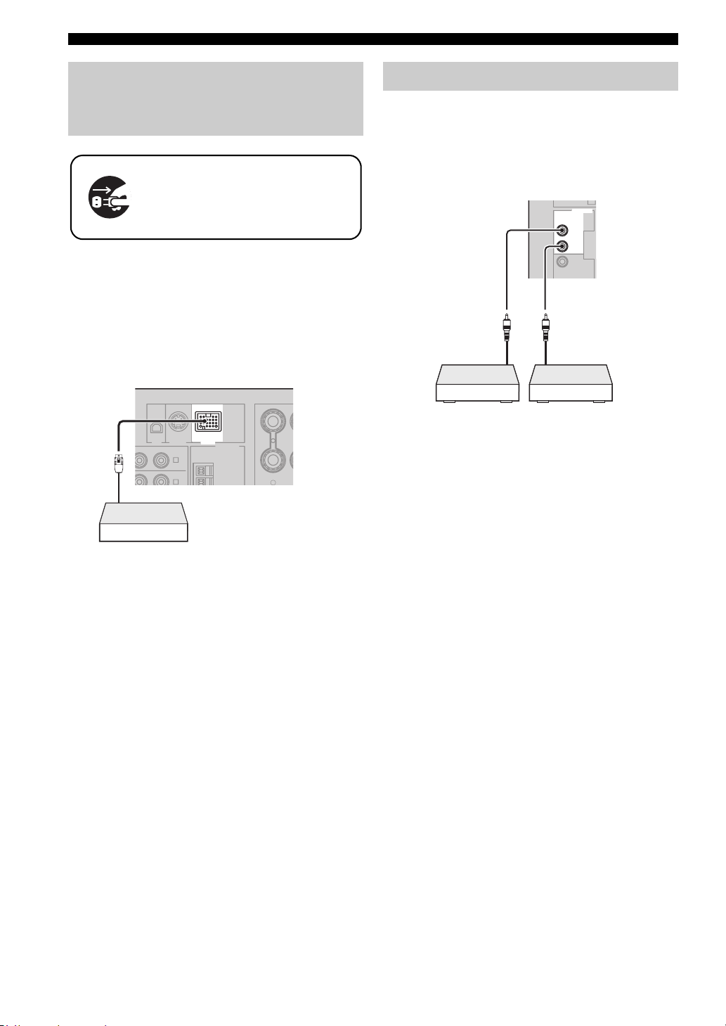
Connecting a Yamaha iPod™
universal dock or Bluetooth
™
adapter
Make sure that this unit and other
components are unplugged from the
AC wall outlets.
This unit is equipped with the DOCK terminal on the rear
panel that allows you to connect a Yamaha iPod universal
dock (such as YDS-10, sold separately) or Bluetooth
adapter (such as YBA-10, sold separately). Connect a
Yamaha iPod universal dock or Bluetooth adapter to the
DOCK terminal on the rear panel of this unit using its
dedicated cable.
XM SIRIUS DOCK
B
P
Yamaha iPod universal dock
or Bluetooth adapter
DTV/CBL
Y
B
C
DOCK
ANTENNA
AM
DVR
GND
SURROUND BA
R
Using REMOTE IN/OUT jacks
When the components are the Yamaha products and have
the capability of the transmission of the remote control
signals, connect the REMOTE IN jack and REMOTE
OUT jack to the remote control input and output jack with
the monaural analog mini cable as follows.
REMOTE
REMOTE
IN
IN
OUT
OUT
+12V
15mA MAX.
Remote
control out
Infrared signal
receiver or
Yam ah a
component
y
• If the components have the capability of the SCENE control
signals, this unit can automatically activate the corresponding
components and start the playback when you use one of the
SCENE buttons. Refer to the owner’s manuals for details about
the capability of the SCENE control signals of the components.
• If the component connected to the REMOTE OUT jack is not
the Yamaha product, set “SCENE IR” in the advanced setup
menu to “OFF” (see page 83).
Remote
control in
Yamah a
component
(CD or DVD
player, etc.)
20 En
Page 25
Connections
R
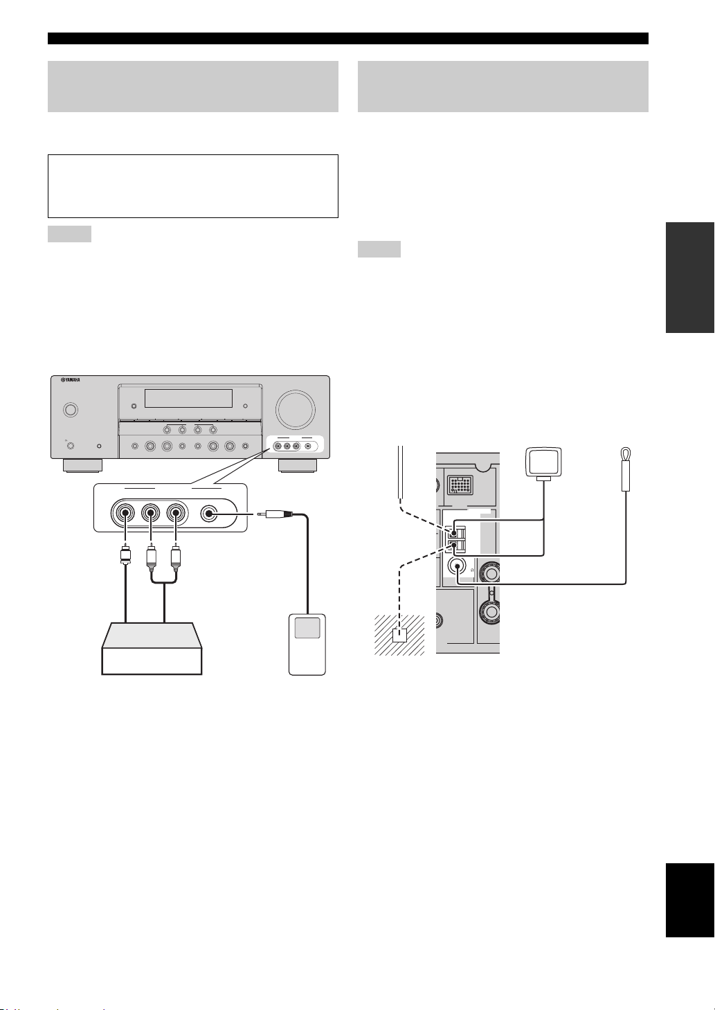
Using the VIDEO AUX jacks on the front panel
Use the VIDEO AUX jacks on the front panel to connect a
game console or a video camera to this unit.
Caution
Be sure to turn down the volume of this unit and other
components before making connections.
Notes
• To reproduce the source signals input at these jacks, select
“V-AUX” as the input source.
• When audio signals are input at the AUDIO jacks, PORTABLE
jack and the DOCK terminal on the rear panel, the priority order
of the input signal is as follows:
1. DOCK
2. PORTABLE
3. AUDIO
VOLUME
ZONE
CONTROL
VIDEO AUX
VIDEO L AUDIO R
PORTABLE
SILENT CINEMA
MAIN ZONE
ON/OFF
PHONES
SYSTEM OFF
EDIT
ZONE 2
ON/OFF
SPEAKERS
A/B/OFF
TONE CONTROL
SEARCH MODE
PRESET/TUNING
CATEGORY
BAND
A/B/C/D/E
1234
EFFECT
SCENE
l
PRESET/TUNING/CH
DIRECTSTRAIGHT
OPTIMIZER MIC
INFO
h
MEMORY
TUNING AUTO/MAN'L
l INPUT hl PROGRAM h
AUDIO SELECT
Connecting the FM and AM antennas
Both FM and AM indoor antennas are supplied with this
unit. Connect each antenna correctly to the designated
terminals. In general, these antennas should provide
sufficient signal strength.
y
See page 22 for connection information of the supplied AM loop
antenna.
Notes
• The AM loop antenna should be placed away from this unit.
• The AM loop antenna should always be connected, even if an
outdoor AM antenna is connected to this unit.
• A properly installed outdoor antenna provides clearer reception
than an indoor one. If you experience poor reception quality,
install an outdoor antenna. Consult the nearest authorized
Yamaha dealer or service center about outdoor antennas.
Outdoor AM antenna
Use a 5 to 10 m (16 to 33
ft) vinyl-covered wire
extended outdoors from a
window.
AM loop
antenna
(supplied)
Indoor FM
antenna
(supplied)
PREPARATION
VIDEO AUX
VIDEO L AUDIO R PORTABLE
V
L
Vid eo
output
Game console or
video camera
R
Audio
output
3.5 mm stereo
mini plug
Audio
output
Portable audio
player
DOCK
ANTENNA
ANTENNA
AM
AM
GND
GND
FM
FM
75
75
UNBAL.
UNBAL.
O
SUB
WOOFER
CENTE
PUT
(U.S.A. model)
Ground (GND terminal)
For maximum safety and minimum interference, connect the
GND terminal to a good earth ground. A good earth
antenna
ground is a metal stake driven into moist earth.
English
21 En
Page 26
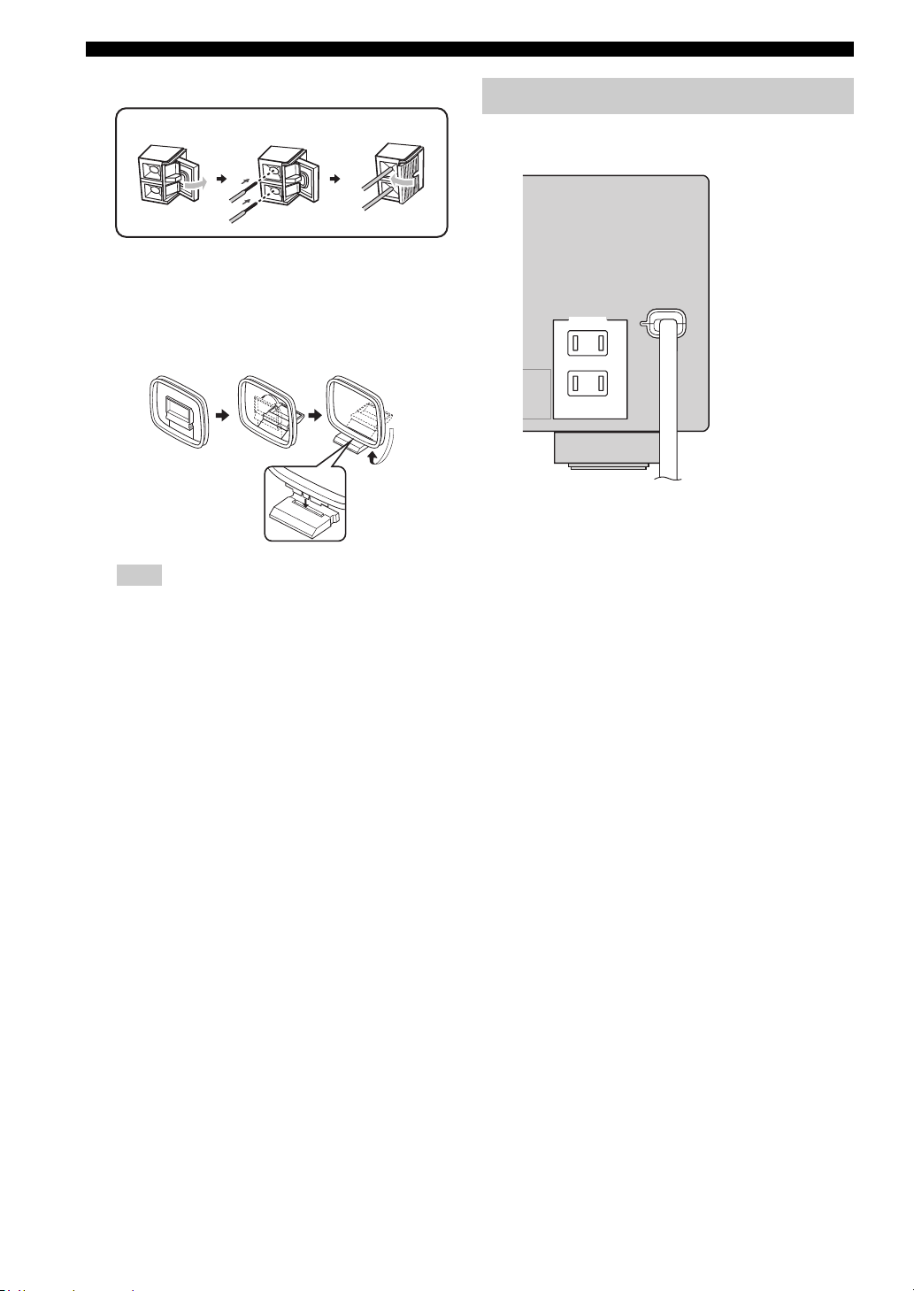
Connections
Connecting the wire of the AM loop antenna
Open the lever
Insert
Close the lever
y
The wire of the AM loop antenna does not have any polarity
and you can connect either end of the wire to AM or GND
terminal.
Assembling the supplied AM loop antenna
Note
The types of the supplied AM loop antenna is different
depending on the models.
Connecting the power cable
Once all connections are complete, plug the power cable
into the AC wall outlet.
(U.S.A. model)
AC OUTLETS
AC OUTLETS
SWITCHED
SWITCHED
Power cable
■ AC OUTLET(S) (SWITCHED)
Australia model...................................................... 1 outlet
Korea model............................................................... None
Other models......................................................... 2 outlets
Use these outlet(s) to supply power to any connected
components. Connect the power cable of your other
components to these outlet(s). Power to these outlet(s) is
supplied when this unit is turned on. However, power to
these outlet(s) is cut off when this unit is set to the standby
mode. For information on the maximum power or the total
power consumption of the components that can be
connected to these outlet(s), see “Specifications” on
page 97.
22 En
Page 27
Connections
Setting the speaker impedance
Caution
If you are to use 6 ohm speakers, set “SP IMP.” to
“6Ω MIN” as follows BEFORE using this unit.
1 Press
2 Press and hold
3 Press
C
SYSTEM OFF on the front panel to
set this unit to the standby mode.
Refer to the right column for details.
N
TONE CONTROL and
then press AMAIN ZONE ON/OFF to turn
on this unit.
This unit turns on, and the advanced setup menu
appears in the front panel display.
TONE CONTROL
O
IMP.”.
“SP IMP.” and the current speaker impedance setting
(“8Ω MIN”) appear in the front panel display.
While holding
down
PROGRAM l / h to select “SP
MAIN ZONE
ON/OFF
Turning on and off the power
■ Turning on this unit
Press AMAIN ZONE ON/OFF (or HPOWER)
to turn on this unit.
y
When you turn on this unit, there will be a 4 to 5-second delay
before this unit can reproduce sound.
■ Set this unit to the standby mode
Press AMAIN ZONE ON/OFF (or
I
STANDBY) to set this unit to the standby
mode.
In the standby mode, this unit consumes a small amount of
power in order to receive infrared signals from the remote
control.
y
You can set the main zone and zone 2 to the standby mode
simultaneously by pressing CSYSTEM OFF.
PREPARATION
4 Press
5 Press
Note
The setting you made is reflected next time you turn on this unit.
P
STRAIGHT repeatedly to select “6Ω
MIN”.
A
MAIN ZONE ON/OFF to save the
new setting and turn off this unit.
English
23 En
Page 28
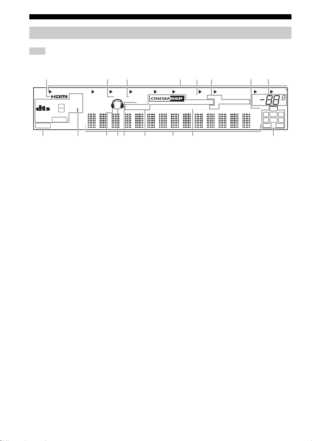
Connections
Front panel display
Note
The XM and SIRIUS indicator is only applicable to the U.S.A. and Canada models and the cursor on the left of the XM indicator or
SIRIUS indicator lights up only when “XM” or “SIRIUS” is selected as the input source.
12345678
MULTI CH
96
24
ES
MATRIX DISCRETE
neural
PCM
q
q
EX
q
DIGITAL
PL x
DVR
V-A UX
DOCK ENHANCER
SP
A B
DTV/CBL
SILENT
ZONE 2
CINEMA
1 HDMI indicator
Lights up when the signal of the selected input source is
input at the HDMI IN jacks (see page 14).
2 DOCK indicator
• Lights up when you station your iPod in a Yamaha
iPod universal dock (such as the YDS-10, sold
separately) connected to the DOCK terminal of this
unit (see page 20) and V-AUX is selected as the input
source. The DOCK indicator also lights up when this
unit is charging the battery of the stationed iPod in the
standby mode.
• Flashes while the connected Yamaha Bluetooth adaptor
(such as YBA-10, sold separately) and the Bluetooth
component is in the paring (see page 61) or the
Bluetooth adaptor is searching the Bluetooth
component (see page 61).
• Lights up while the connected Yamaha Bluetooth
adaptor is connected to the Bluetooth component (see
page 20).
3 ENHANCER indicator
Lights up when the Compressed Music Enhancer mode is
selected (see page 40).
4 Input source indicators
The corresponding cursor lights up to show the currently
selected input source.
5 YPAO indicator
Lights up when you run “AUTO SETUP” and when the
speaker settings set in “AUTO SETUP” are used without
any modifications (see page 26).
DVD CD
MD/CD-R
SLEEP
YPAO
VIRTUAL
TUNER SIRIUS
MEMORY
AUTO
TUNED
HOLD
STEREO
VOL.
MUTE
ft
ms
dB
XM
96/24
LFE
LL C R
SL SB SR
GFECB DA09
6 Tuner indicators
Lights up when this unit is in the FM, AM, XM Satellite
Radio or SIRIUS Satellite Radio tuning mode (see
pages 45 to 58).
7 96/24 indicator
Lights up when a DTS 96/24 signal is input to this unit.
8 MUTE indicator and VOLUME level indicator
• The MUTE indicator flashes while the MUTE function
is on (see page 37).
• Indicates the current volume level.
9 PCM indicator
Lights up when this unit is reproducing PCM (Pulse Code
Modulation) digital audio signals.
0 Decoder indicators
The respective indicator lights up when any of the
decoders of this unit function.
A Headphone indicator
Lights up when headphones are connected (see page 37).
B SP A B indicators
Light up according to the set of front speakers activated
(see page 35).
SP A: The FRONT A speakers are activated.
SP B: The FRONT B speakers are activated.
C ZONE2 indicator
Lights up when Zone 2 is turned on (see page 80).
dB
SBRSBL
24 En
Page 29
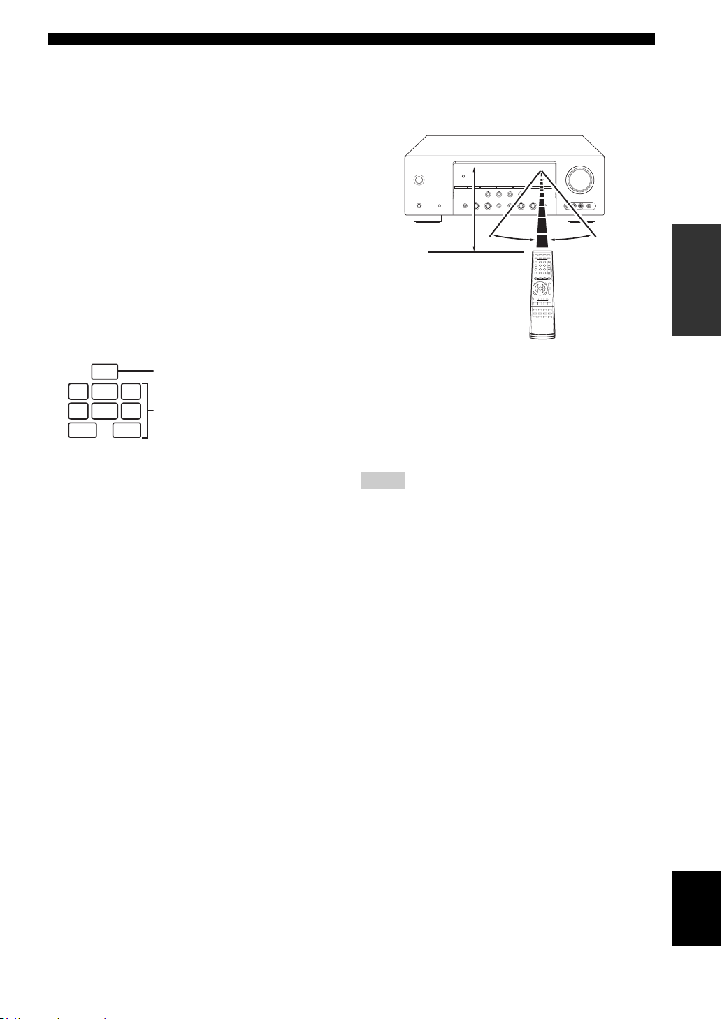
Connections
D CINEMA DSP indicator
Lights up when you select a sound field program (see
page 41).
VIRTUAL indicator
Lights up when Virtual CINEMA DSP is active (see
page 41).
SILENT CINEMA indicator
Lights up when headphones are connected and a
sound field program is selected (see page 41).
E Multi-information display
Shows the name of the current sound field program and
other information when adjusting or changing settings.
F SLEEP indicator
Lights up while the sleep timer is on (see page 39).
G Input channel and speaker indicators
LFE
LFE indicator
LL C R
SL SB SR
Input channel indicators
SBRSBL
Input channel indicators
• Indicate the channel components of the current
digital input signal.
• Light up or flash according to the settings of the
speakers when this unit is in the automatic setup
procedure (see page 26) or the speaker level setting
procedure in the “SP LEVEL” (see page 67).
■ Using the remote control
The remote control transmits a directional infrared ray.
Be sure to aim the remote control directly at the remote
control sensor on this unit during operation.
Approximately
6 m (20 ft)
1Infrared window
Outputs infrared control signals. Aim this window at the
component you want to operate.
y
To set the remote control codes for other components, see
page 78.
Notes
• Do not spill water or other liquids on the remote control.
• Do not drop the remote control.
• Do not leave or store the remote control in the following types
of conditions:
– places of high humidity, such as near a bath
– places of high temperature, such as near a heater or stove
– places of extremely low temperatures
– dusty places
30º 30º
PREPARATION
25 En
English
Page 30
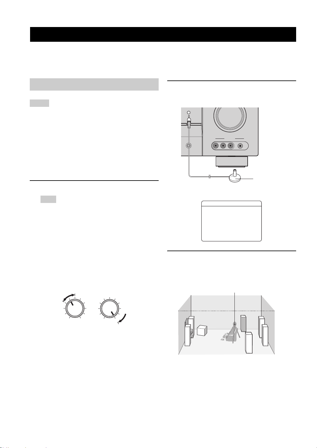
Optimizing the speaker setting for your listening room
Optimizing the speaker setting for your listening room
This unit employs the YPAO (Yamaha Parametric Room Acoustic Optimizer) technology which lets you avoid
troublesome listening-based speaker setup and achieves highly accurate sound adjustments automatically. The supplied
optimizer microphone collects and this unit analyzes the sound your speakers produce in your actual listening
environment.
Using AUTO SETUP
Notes
• Be advised that it is normal for loud test tones to be output
during the “AUTO SETUP” procedure.
• To achieve the best results, make sure the room is as quiet as
possible while the “AUTO SETUP” procedure is in progress. If
there is too much ambient noise, the results may not be
satisfactory.
y
You can run “AUTO SETUP” using the system menu that appears
in the OSD or in the front panel display. This manual uses the
OSD illustrations to explain the “AUTO SETUP” procedure.
1 Make sure of the following check points.
Note
Before starting the automatic setup, check the following
check points.
❏ Speakers are connected appropriately.
❏ Headphones are disconnected from this unit.
❏ This unit and the video monitor are turned on.
❏ This unit is selected as the video input source of
the video monitor.
❏ The connected subwoofer is turned on and the
volume level is set to about half way (or slightly
less).
❏ The crossover frequency controls of the
connected subwoofer is set to the maximum.
VOLUME
CROSSOVER
HIGH CUT
2 Connect the supplied optimizer microphone
to the OPTIMIZER MIC jack on the front
panel.
OPTIMIZER MIC
ZONE
CONTROL
/MAN'L
VIDEO AUX
AUDIO SELECT
VIDEO L AUDIO R PORTABLE
Optimizer
microphone
The following display appears in the OSD.
AUTO SETUP
SETUP;;;;;;;AUTO
. START
Automatic
Processing
of all item
p
[ ]/[ ]:Up/Down
p
[ ]/[ ]:Select
[
p
3 Place the optimizer microphone at your
normal listening position on a flat level
surface with the microphone heading
upward.
Optimizer microphone
MIN
MAX
Controls of a subwoofer (example)
MIN MAX
❏ FRONT A speakers are selected as the front
speaker system (see page 35).
❏ The room is sufficiently quiet.
26 En
y
It is recommended that you use a tripod (etc.) to affix the
optimizer microphone at the same height as your ears would be
when you are seated in your listening position. You can use the
attached screw of a tripod (etc.) to fix the optimizer microphone
to the tripod (etc.).
Page 31

Optimizing the speaker setting for your listening room
4 Make sure that “SETUP” is set to “AUTO”
and the pointer is pointing at “START”.
y
You can also select the following setup methods. In this
8
case, press
select the one of the following choises and then select
“START”.
k to select “SETUP”, press
Choices: AUTO, RELOAD, UNDO, DEFAULT
• Select “AUTO” to automatically run the entire
“AUTO SETUP” procedure.
• Select “RELOAD” to reload the last “AUTO
SETUP” settings and override the previous
settings.
• Select “UNDO” to undo the last “AUTO SETUP”
settings and restore the previous settings.
• Select “DEFAULT” to reset the “AUTO SETUP”
parameters to the initial factory settings.
Note
“RELOAD” or “UNDO” is available only when you have
previously run “AUTO SETUP” and confirmed the results.
5 Press
8
n to select “START” and then press
8
ENTER to start the setup procedure.
The following message appears in the OSD.
8
l / h to
6 Press
8
ENTER to start the setup
procedure.
This unit starts the auto setup procedure. Loud test
tones are output from each speaker during the auto
setup procedure. Once all items are set, the result
display appears in the OSD.
Notes
• During the auto setup procedure, do not perform any
operation on this unit.
• We recommend getting out of the room while this unit is in
the auto setup procedure. It takes approximately 3 minutes
for this unit to complete the auto setup procedure.
This unit performs the following checks:
Speaker wiring/volume level WIRING/LEVEL
Checks which speakers are connected and the
polarity of each speaker. Also checks and adjusts the
volume level of each speaker.
Speaker distance DISTANCE
Checks the distance of each speaker from the
listening position and adjusts the timing of each
channel.
PREPARATION
NOTICE
Loudtesttonesare
output.
Pleasekeepquiet
orleavetheroom.
Press[ENTER]
Before proceeding next operation
Once you perform the next operation, this unit starts the
automatic setup procedure. For more accurate
measurements, keep quiet and move to the wall where
speakers are not around. We recommend that you leave
the listening room during the automatic setup
procedure.
Speaker size SIZE
Checks the frequency response of each speaker and
sets the appropriate low-frequency crossover for each
channel.
English
27 En
Page 32

Optimizing the speaker setting for your listening room
The display changes as follows.
AUTO SETUP
SETUP;;;;;;;AUTO
. START
Automatic
Processing
of all item
p
[ ]/[ ]:Up/Down
p
[ENTER]:Start
7 Press
8
k and 8ENTER to display the
setup results in detail.
8 Press
8
l / h repeatedly to toggle between
the setup result displays.
Results of the speaker
connection and wiring
AUTO SETUP
INITIALIZING
. WIRING/LEVEL
DISTANCE
SIZE
WAITING;;;
;;;;;;;;;;
[
[]:Exit
AUTO SETUP
RESULT
SP : 3/2/0.1
DIST: 3.2/3.5m
LVL : -2/+2dB
. SET CANCEL
>
[ ]/[ ]:Up/Down
[ENTER]:Enter
The results displayed under “RESULT” are as follows.
Number of speakers SP
Displays the number of speakers connected to this unit in
the following order:
Front/Back/Subwoofer
Speaker distance DIST
Displays the speaker distance from the listening position
in the following order:
Closest speaker distance/Farthest speaker distance
Speaker level LVL
Displays the speaker output level in the following order:
Lowest speaker output level/Highest speaker output level
Results of the speaker
distance from the
listening position
Results of the speaker
size
Results of the speaker
output level
y
If you are not satisfied with the results or want to manually
adjust each parameter, run “MANUAL SETUP” (see
page 63).
Note
The distances displayed in the “DISTANCE” results may be
longer than the actual distance depending on the
characteristics of your speakers.
9 Press
8
ENTER to return to the result
display.
AUTO:RESULT
Notes
• If “E-9:INTERNAL ERROR” appears during the testing
procedure, restart from step 4.
• If you selected “RELOAD” in step 4, no test tones are output.
• If an error occurs during the “AUTO SETUP” procedure, the
setup procedure is canceled and an error screen appears. For
details, see “If an error screen appears” on page 29.
• When this unit detects potential problems during the “AUTO
SETUP” procedure, “WARNING” and the number of warning
messages appears (see page 29).
28 En
. RESULT
SP : 3/2/0.1
DIST: 3.2/3.5m
LVL : -2/+2dB
SET CANCEL
>
[ ]/[ ]:Up/Down
[ENTER]:Detail
Page 33

10 Press
8
n and then press 8l / h to select
“SET” or “CANCEL”.
Choices: SET, CANCEL
• Select “SET” to confirm the “AUTO SETUP”
results.
• Select “CANCEL” to cancel the “AUTO SETUP”
results.
11 Press
8
ENTER to confirm your selection.
The top “SET MENU” display appears in the OSD.
SET MENU
TOP MENU
.;AUTO SETUP
;MANUAL SETUP
.A;SIGNAL INFO
p
[ ]/[ ]:Up/Down
p
[ENTER]:Enter
12 Press
M
MENU to exit from “SET MENU”.
13 Disconnect the optimizer microphone from
this unit.
The optimizer microphone is sensitive to heat. Keep it
away from direct sunlight and do not place it on top
of this unit.
y
If you change speakers, speaker positions, or the layout of your
listening environment, run “AUTO SETUP” again to recalibrate
your system.
■ If an error screen appears
Press 8k / n / l / h to select “RETRY” or
“EXIT” and then press 8ENTER.
The following display is an example where “E-8:USER
CANCEL” appears in the OSD.
ERROR
. E-8:USER CANCEL
Can't detect
signal at MIC
RETRY EXIT
>
[ ]/[ ]:Select
[ENTER]:Enter
Choices: RETRY, EXIT
• Select “RETRY” to retry the “AUTO SETUP”
procedure.
• Select “EXIT” to exit from the “AUTO SETUP”
procedure.
Optimizing the speaker setting for your listening room
■ If “WARNING” appears
When this unit detects potential problems during the
“AUTO SETUP” procedure, “WARNING” appears in the
result display. Check the warning messages to correct your
speaker settings.
Note
Warnings differ from errors in that warnings do not cancel the
“AUTO SETUP” procedure.
1 Make sure the pointer is pointing at
“WARNING” and then press 8ENTER to
display the detailed information about the
warning.
The number on the right of “WARNING” indicates
the number of warning messages.
AUTO SETUP
. WARNING(2)
RESULT
SP : 3/2/0.1
DIST: 3.2/3.5m
LVL : -2/+2dB
SET CANCEL
>
[ ]/[ ]:Up/Down
[ENTER]:Detail
2 Press
3 Press
8
l / h repeatedly to toggle between
the warning displays.
WARNING
W-1:OUT OF PHASE
Reverse channel
AAAAFLAAAAA---
AAACENTER
AAAASLAAAAA---
AAAASBLAAAA---
[ ]/[ ]:Select
[ENTER]:Return
y
• For details about each warning message, see the “AUTO
SETUP” section in “Troubleshooting” on page 90.
• When the corresponding warning message is not
applicable to a speaker, “–
8
ENTER to return to the result
–” is displayed instead.
display.
PREPARATION
29 En
English
Page 34

SELECTING THE SCENE TEMPLATES
Selecting the SCENE templates
This unit is equipped with 17 preset SCENE templates for
various situations of using this unit. As the initial factory
setting, the following SCENE templates are assigned to
each SCENE button:
2 Press
R
INPUT l / h (or press 5AMP and
then press 8l / h) to select the desired
template.
SCENE 1: DVD Viewing
SCENE 2: Disc Listening
SCENE 3: TV Viewing
SCENE 4: Radio Listening
If you want to use other SCENE templates, you can select
the desired SCENE templates from the SCENE template
library and assign the templates to the selected SCENE
buttons on the front panel and the remote control.
Select the desired SCENE
SCENE template library
template
(Image)
1
Assign the
SCENE
template to the
SCENE button
Selecting the desired SCENE template
l INPUT h
Front panel
or
AMP
ENTER
Remote control
DVD MovieView
3 Press the TSCENE (or
again to confirm the selection.
The selected SCENE template is assigned to the
button.
1
6
SCENE) button
or
1
1 Press and hold the desired TSCENE (or
6
SCENE) button for 3 seconds.
The indicator on the selected SCENE button on the
front panel starts to flash, and the name of the
currently assigned SCENE template appears in the
front panel display.
3 seconds
1
Front panel
or
1
Flashes
3 seconds
1
Remote control
DVD Viewing
30 En
Remote controlFront panel
Note
Once the desired SCENE templates are assigned to the
corresponding SCENE buttons, you may need to set the input
source of the SCENE template on the remote control. See page 34
for details.
Page 35

■ Which SCENE template would you like to select?
Selecting the SCENE templates
Which source do you like to
play back?
Video sources
(DVD video,
Recorded video)
Music discs (CD, SACD
or DVD-Audio)
Radio programs
Which component do you
like for playback?
DVD
DVR
DVD
CD
TUNER (FM/AM)
XM
SCENE templates
DVD V iewing
DVD Movie Viewing
DVD L iv e Viewin g
DVR V iewing
Disc Hi-fi Listening
Music Disc Listening
Disc Listening
CD Hi-fi Listening
CD Listening
CD Music Listening
Radio Listening
XM Listening
Default
SCENE buttons
1
2
OPERATION
BASIC
4
SIRIUS Listening
Dock Listening
TV Viewing
3
iPod or Bluetooth
component
TV programs
SIRIUS
DOCK
DTV/CBL
TV Sports Viewing
Video games
V-AUX
*
Game Playing
Note
*
When iPod is connected to the Yamaha iPod universal dock or a Bluetooth component is connected to the Bluetooth adapter, this unit
plays back the audio sources input at the DOCK terminal.
y
You can create your original SCENE templates by editing the preset SCENE templates. See page 33 for details.
English
31 En
Page 36

Selecting the SCENE templates
■ Preset SCENE templates descriptions
The illustrations of the SCENE button in the following table indicate the assigned SCENE buttons in the default setting.
SCENE template Input source Playback mode Features
DVD Viewing
11
DVD Movie Viewing
DVD Live Viewing
DVR Viewing
Disc Hi-fi Listening
Music Disc
Listening
Disc Listening
2
CD Hi-fi Listening
CD Listening
CD Music Listening
Radio Listening
14
*
DVD
DVD
*
STRAIGHT
MOVIE
Movie Dramatic
*
DVD
MUSIC
Pop/Rock
DVR MOVIE
Movie Dramatic
*
DVD
DVD
*
DIRECT
STEREO
2ch Stereo
*
DVD
STEREO
7ch Stereo
*
CD
CD
*
DIRECT
STEREO
7ch Stereo
*
CD
STEREO
2ch Stereo
TUNER MUSIC ENHANCER
7ch Enhancer
Select this SCENE template when you play back general
contents on the DVD player.
Select this SCENE template when you play back movies on
your DVD player.
Select this SCENE template when you enjoy the music live
video on your DVD player.
Select this SCENE template when you play back movies on
your digital video recorder.
Select this SCENE template when you enjoy the high fidelity
sound of the music discs on your DVD player.
Select this SCENE template when you play back music discs
on your DVD player.
Select this SCENE template when you play back music
sources on your DVD player as the background music.
Select this SCENE template when you enjoy the high fidelity
sound of the music discs on your CD player.
Select this SCENE template when you play back music discs
on your CD player as the background music.
Select this SCENE template when you play back music source
on your CD player.
Select this SCENE template when you enjoy FM or AM radio
programs.
XM Listening
SIRIUS Listening
Dock Listening
TV Viewing
13
TV Sports Viewing
Game Playing
XM MUSIC ENHANCER
7ch Enhancer
SIRIUS MUSIC ENHANCER
7ch Enhancer
DOCK MUSIC ENHANCER
7ch Enhancer
DTV/CBL STRAIGHT
DTV/CBL ENTERTAINMENT
TV Sports
V-AUX ENTERTAINMENT
Select this SCENE template when you enjoy XM Satellite
Radio programs.
Select this SCENE template when you enjoy SIRIUS Satellite
Radio programs.
Select this SCENE template when you play back music on
your iPod stationed in a Yamaha iPod universal dock or
Bluetooth component that is connected to the Bluetooth
adapter.
Select this SCENE template when you enjoy general
programs on your TV.
Select this SCENE template when you enjoy sports programs
on your TV.
Select this SCENE template when you play video games.
Game
*
When the connected DVD player or CD player has the capability of the SCENE control signals and is connected to the REMOTE
OUT jack of this unit, this unit operates the DVD player or CD player worked with the SCENE features.
32 En
Page 37

Selecting the SCENE templates
Creating your original SCENE templates
You can create your original SCENE templates for each
SCENE button. You can refer to the preset 17 SCENE
templates to create the original SCENE templates.
■ Customizing the preset SCENE
templates
Use this feature to customize the preset SCENE templates.
Select a SCENE template
SCENE template library
(Image)
Create the original SCENE
template
SCENE : DVD Viewing
: DVD
INPUT
: DVD Viewing
SCENE
1
Assign to the SCENE
button
3 Press
5
AMP and then 8k / n to select the
desired parameter of the SCENE template
and then 8l / h to select the desired value
of the selected parameter.
You can adjust the following parameters for a SCENE
template:
• INPUT: The input source component
• MODE: The active sound field programs,
STRAIGHT or DIRECT mode (see
pages 41 and 43)
• NIGHT: The night listening mode setting (see
page 44)
− SYSTEM: Keeps the current night listening
mode.
− CINEMA: Sets the night listening mode to the
CINEMA mode.
− MUSIC: Sets the night listening mode to the
MUSIC mode.
4 Press the
6
SCENE button again to confirm
the edit.
1
OPERATION
BASIC
1 Turn on the video monitor connected to this
unit.
2 Press and hold the desired
for 3 seconds.
The SCENE template customizing screen appears on
the video monitor.
AMP
Note
When the SCENE template you want to customize is not
assigned to any of the 6SCENE buttons, press 5AMP
and then press 8l / h repeatedly to recall the desired
SCENE template on the menu screen.
6
SCENE button
1
3 seconds
y
An asterisk mark (*) appears by the name of the original SCENE
template.
Notes
• Once the desired SCENE templates are assigned to the
corresponding 6SCENE buttons, you may need to set the
input source of the SCENE template on the remote control. See
page 34 for details.
• You can create a customized SCENE template for each
6
SCENE button, and if you create another customized
SCENE template, this unit overwrites the old customized
SCENE template with the new one.
• The newly created template is only available for the assigned
6
SCENE button.
■ Renaming the SCENE templates
Select the name of the SCENE template at step 3
of “Customizing the preset SCENE templates”
and then press 8ENTER.
• Press 8k / n to select the desired character.
•Press
• Press 9RETURN to cancel the new name.
• Press 8ENTER to confirm the new name.
8l / h to place “_” (underscore) under the
space or the desired character.
English
33 En
Page 38

Selecting the SCENE templates
Using remote control on the SCENE feature
■ Controlling the input source
components in the SCENE mode
You can operate both this unit and the input source
component by using the remote control. You must set the
appropriate remote control code for each input source in
advance (see page 78).
1 Press the desired
6
SCENE button on the
remote control.
2 Press the desired buttons in the * area below
to control the input source component of the
selected SCENE template.
POWER
STANDBY
POWER
POWER
AVTV
AXMSIRIUS
CD MD/CD-R TUNER
DVD
V-AUX/DOCK
AMP
*
BAND LEVEL
TITLE
RETURN
MEMORY
REC
INFO
l PROG h
STRAIGHT DIRECT
MULTI CH IN AUDIO SEL
DTV/CBL DVR
BC
TV INPUT
SCENE
ENTER
TV MUTE
SRCH MODE
ENHANCER
NIGHT
MUTE
TV CH
TV VOL
4321
SCENE buttons
VOLUME
MENU
DISPLAY
SUR. DECODE
4321
PARAMETER
81070965
SLEEP
ENT
■ Setting input source of the customized
SCENE template on the remote control
If you customize the input source of the selected SCENE
template, you must set the input source of the SCENE
template on the remote control to operate the input source
component correctly.
Press and hold the 6SCENE button and the
desired input selector button (4) for 3 seconds.
y
Press the 6SCENE button again to operate the input source
component.
Note
*
These buttons control the input source component. See page 77
for details of the function of each button.
34 En
Page 39

Playback
PLAYBACK
Caution
Extreme caution should be exercised when you play
back CDs encoded in DTS. If you play back a CD
encoded in DTS on a DTS-incompatible CD player,
you will only hear some unwanted noise that may
damage your speakers. Check whether your CD player
supports CDs encoded in DTS. Also, check the sound
output level of your CD player before you play back a
CD encoded in DTS.
Basic operations
1 Turn on the video monitor connected to this
unit.
2 Press
3 Press
4 Start playback on the selected component or
M
SPEAKERS repeatedly to select the
front speakers you want to use.
The respective speaker indicators lights up in the
front panel display.
R
INPUT l / h repeatedly (or press
one of the input selector buttons (4)) to
select the desired input source.
The name of the currently selected input source
appears in the front panel display for a few seconds.
Available input sources
MULTI CH
DVR
V-AUX
DTV/CBL
DVD C D
MD/CD-R
TUNER SIRIUS
XM
INPUT:DVD
Currently selected input
source
select a broadcast station.
• Refer to the operating instructions for the source
component.
• See page 45 for details about FM/AM tuning
instructions.
• See page 48 for details about XM Satellite Radio
tuning instructions.
• See page 53 for details about SIRIUS Satellite
Radio tuning instructions.
5 Rotate
L
VOLUME (or press
NVOLUME +/–) to adjust the volume to the
desired output level.
6 Press
O
PROGRAM l / h repeatedly (or
press 5AMP and then BPROG l / h
repeatedly) to select the desired sound field
program.
The name of the selected sound field program appears
in the front panel display.
See page 40 for details about sound field programs.
Movie Dramatic
Currently selected
surround field program
Notes
• Choose a sound field program based on your listening
preference, not merely on the name of the program.
• When you select an input source, this unit automatically selects
the last sound field program used with the corresponding input
source.
• Sound field programs cannot be selected when the component
connected to the MULTI CH INPUT jacks is selected as the
input source (see page 36).
• When PCM signals with a sampling frequency higher than 48
kHz are input, this unit is automatically set to the “STRAIGHT”
mode (see page 41).
• To display information about the currently selected input source
in the OSD, see page 38 for details.
■ A quick guide to contents
When you want to...
Enjoy high-quality sound 43
Adjust the tonal quality of the front speakers 43
Adjust the parameters of sound field programs 42
Enjoy the sources with a wide dynamic range at night 44
Use headphones 37
Select a decoder to play back sources with 41
Automatically set this unit to the standby mode 39
See
page
OPERATION
BASIC
35 En
English
Page 40

Playback
Selecting audio input jacks (AUDIO SELECT)
This unit comes with a variety of input jacks. Use this
feature (audio input jack select) to switch between input
jacks when more than one input jack is assigned to as the
same input source.
y
• We recommend setting the audio input jack select to “AUTO”
in most cases.
• You can adjust the default audio input jack select of this unit by
using “AUDIO SELECT” in “OPTION MENU” (see page 74).
Press SAUDIO SELECT (or press 5AMP and
then FAUDIO SEL) repeatedly to select the
desired audio input jack select setting.
Available input sources
MULTI CH
DVR
V-AUX
DTV/CBL
DVD C D
MD/CD-R
TUNER SIRIUS
XM
A.SEL:AUTO
Currently selected audio input jack select setting
Selecting the MULTI CH INPUT component
Use this feature to select the component connected to the
MULTI CH INPUT jacks (see page 19) as the input
source.
Press RINPUTl / h repeatedly (or press
5
AMP and then EMULTI CH IN) to select
MULTI CH.
“MULTI CH” appears in the front panel display.
y
Use “MULTI CH SET” menu in “INPUT MENU” to set the
parameters for MULTI CH INPUT (see page 72).
Note
The input signals are amplified and output directly without sound
processing. Therefore, you cannot activate sound field programs,
the night listening mode, etc. while MULTI CH is selected as the
input source.
AUDIO SELECT Function
AUTO
HDMI
COAX/OPT
ANALOG
Automatically selects input signals in the
following order: (1) HDMI (2) Digital
signals (3) Analog signals
Selects only HDMI signals. When HDMI
signals are not input, no sound is output.
Selects only digital signals. When no
signals are input, no sound is output.
Selects only analog signals. If no analog
signals are input, no sound is output.
Note
This feature is not available when no digital input jacks
(OPTICAL, COAXIAL and HDMI) are assigned. In addition,
HDMI is not available as an audio input jack select setting when
the HDMI IN DVD and HDMI IN DTV/CBL jacks are not used.
Use “INPUT ASSIGNMENT” in “INPUT MENU” to reassign
the respective input jack (see page 71).
36 En
Page 41

Playback
Displaying the current status of this unit on a video monitor
You can display the operating information of this unit on a
video monitor.
1 Turn on the video monitor connected to this
unit.
2 Press
y
You can select the amount of time that the current status is
displayed in the OSD by using the “OSD-AMP” parameter in
“OPTION MENU” (see page 73).
Note
The OSD signal is not output at the DVR VIDEO OUT jacks and
will not be recorded.
O
DISPLAY.
The current status screen appears in the OSD.
STATUSVOL:-40dB
DVDMovieViewing
MOVIE
MovieSpacious
INPUT:DVD
A.SEL:HDMI
NIGHT:CINEMA(MID)
[DISPLAY]:STATUSOFF
Using your headphones
Connect a pair of headphones with a stereo
analog audio cable plug to the PHONES jack on
the front panel.
OPERATION
BASIC
y
When you select a sound field program, SILENT CINEMA mode
is automatically activated (see page 41).
Notes
• When you connect headphones, no signals are output at the
speaker terminals.
• All Dolby Digital and DTS audio signals are mixed down to the
left and right headphone channels.
Muting the audio output
Press JMUTE to mute the audio output. Press
J
MUTE again to resume the audio output.
y
• You can also rotate LVOLUME or press NVOLUME +/– to
resume the audio output.
• You can adjust the muting level by using the “MUTE TYPE”
parameter in “SOUND MENU” (see page 69).
• The MUTE indicator flashes in the front panel display when the
audio output is muted and disappears from the front panel
display when the audio output is resumed.
English
37 En
Page 42

Playback
Playing video sources in the background of an audio source
You can combine a video image from a video source with
sound from an audio source. For example, you can enjoy
listening to classical music while viewing beautiful
scenery from the video source on the video monitor.
Press the input selector buttons (4) control to
select a video source and then an audio source.
XM SIRIUS
CD MD/CD-R TUNER
DVD
DTV/CBL DVR
DVD
V-AU X
Audio sources
Video sources
y
• You can also select “MULTI CH” as the audio source (see
page 36). Press 5AMP and then press EMULTI CH IN.
• Set the “BGV” parameter in the “MULTI CH SET” menu to the
desired setting to select the default background video input
source of the MULTI CH INPUT sources (see page 72).
Displaying the input source information
You can display the format, sampling frequency, channel,
bit rate and flag data of the current input signal.
1 Press
5
AMP and then MMENU.
The top “SET MENU” display appears in the OSD.
■ Audio information
Information Descriptions
FORMAT
SAMPLING
CHANNEL
BITRATE
FLAG
Signal format. When this unit cannot detect a
digital signal, it automatically switches to
analog input.
The number of samples per second taken from
a continuous signal to make a discrete signal.
The number of source channels in the input
signal (front/surround/LFE). For example, a
multi-channel soundtrack with 3 front
channels, 2 surround channels and LFE, is
displayed as “3/2/0.1”.
The number of bits passing a given point per
second.
Flag data encoded in DTS, Dolby Digital, or
PCM signals that cue this unit to automatically
switch decoders.
Note
“–––” appears when this unit cannot display the corresponding
information.
■ Video information
Information Descriptions
HDMI SIGNAL
HDMI RES.
HDMI ERROR
(Only when error
is detected)
Type of the source video signals and the
video signals output at the HDMI OUT
jack of this unit.
Resolution of the HDMI signals input or
output at the HDMI IN/OUT jacks of this
unit.
Error message for HDMI sources or
connected HDMI devices. See “HDMI
error and message” for details.
SET MENU
TOP MENU
.;AUTO SETUP
;MANUAL SETUP
.A;SIGNAL INFO
p
[ ]/[ ]:Up/Down
p
[ENTER]:Enter
2 Press
8
n repeatedly to select “SIGNAL
INFO” and then press 8ENTER.
The audio information about the input source appears
in the OSD.
3 Press
8
l / h to toggle between the audio
and video information displays.
4 Press
M
MENU again to exit from “SET
MENU”.
38 En
Note
“–––” appears when this unit cannot display the corresponding
information.
HDMI error and message
Message Cause
DEVICE OVER
HDCP ERROR
OUT OF RES.
The number of the connected HDMI
components is over the limit.
HDCP authentication failed.
The connected monitor is not compatible
with the resolution of the input video signal.
Page 43

Using the sleep timer
Use this feature to automatically set the main zone to the
standby mode after a certain amount of time.
Press 5AMP and then press TSLEEP
repeatedly to set the amount of time.
Each time you press NSLEEP, the front panel display
changes as shown below.
SLEEP 120min SLEEP 90min
SLEEP 60minSLEEP 30minSLEEP OFF
The SLEEP indicator flashes while you are switching the
amount of time for the sleep timer. Once the sleep timer is
set, the SLEEP indicator lights up in the front panel
display, and the display returns to the selected sound field
program.
y
• To cancel the sleep timer, press 5AMP and then press
N
SLEEP repeatedly until “SLEEP OFF
panel display.
• The sleep timer setting can also be canceled by pressing
A
MAIN ZONE ON/OFF (or ISTANDBY) to set the main
zone to the standby mode.
” appears in the front
Playback
OPERATION
BASIC
39 En
English
Page 44

SOUND FIELD PROGRAMS
Sound field programs
This unit is equipped with a variety of precise digital
decoders that allow you to enjoy multi-channel playback
from almost any stereo or multi-channel sound source.
Press OPROGRAM l / h (or press 5AMP and
then press BPROG l / h repeatedly).
The name of the selected sound field program appears in
the front panel display.
Notes
• When you select an input source, this unit automatically selects
the last sound field program used with the corresponding input
source.
• Sound field programs cannot be selected when the component
connected to the MULTI CH INPUT jacks is selected as the
input source (see page 36).
• When PCM signals with a sampling frequency higher than 48
kHz are input, this unit is automatically set to the “STRAIGHT”
mode (see page 41).
y
Choose a sound field program based on your listening preference,
not merely on the name of the program itself.
Sound field program descriptions
Category Program Features
CINEMA DSP processing. This program presents an image of pop, rock, or jazz live
concert. The sound field reproduces the spaciousness of a massive pavilion with an emphasis
on the vividness of vocals on the stage and solo instruments and the beats of rhythm
instruments.
CINEMA DSP processing. This sound field is suitable for classic and orchestral music. The
program uses data collected in a large concert hall in Munich. You can enjoy delicate and
beautiful reverberation and a majestic atmosphere.
CINEMA DSP processing. The sound field is suitable for jazz and fusion music. It uses data
collected in a famous jazz club in New York. You can enjoy clear reverberation.
CINEMA DSP processing. You can enjoy dynamic and thrilling sound effects as you play
games. The program lets you feel the depth and three-dimensional surrounding sounds of the
field where you are playing, and offers cinema-like surrounding sound effects for the scenes
of movies.
CINEMA DSP processing. You can enjoy sports relays broadcast in stereo and variety shows
with a live sound environment. For sports relays, the voices of commentators and
announcers come clearly from the center; the cheers and atmosphere in the stadium spread
around within a comfortable range, and you can feel like as if you are in the stadium.
CINEMA DSP processing. The sound field is suitable for movies with an emphasis on
spectacular sound effects, and is a perfect fit with a wide screen. The program reproduces a
wide dynamic range from minimum sound effects to powerful sounds.
CINEMA DSP processing. This sound field is also suitable for movies with an emphasis on
three-dimensional sound effects. It restrains reverberation to an moderate extent, but
reproduces sound effects and background music in a soft, three-dimensional manner with
clarity and center orientation of voices as pivots.
Downmixes multi-channel sources to 2 channel or plays back 2-channel sources as they are.
CINEMA DSP processing. Using this program increases the listening position range. This is
a sound field suitable for background music at parties.
Select these programs to play back compression artifacts (such as the MP3 format) in
2-channel or 7-channel stereo. This program enhances your listening experience by
regenerating the missing harmonics in a compression artifact.
MUSIC
ENTERTAINMENT
MOVIE
STEREO
MUSIC
ENHANCER
Pop/Rock
Hall
Jazz
Game
TV Sports
Movie Spacious
Movie Dramatic
2ch Stereo
7ch Stereo
2ch Enhancer
7ch Enhancer
Note
The sound field programs of this unit are recreations of real-world acoustic environments made from precise measurements taken in the
actual concert hall, music venue, movie theater, etc. Thus, you may notice variations in the strength of the reflections coming from each
direction.
40 En
Page 45

Sound field programs
■ Enjoying 2-channel sources using the
standard decoders
Signals input from 2-channel sources can also be played
back on multi-channels.
Press 5AMP and then press
repeatedly to select a decoder.
You can select from the following decoders depending on
the type of source you are playing and your personal
preference.
Decoder Functions
Pro Logic
PLII Movie
PLIIx Movie
PLII Music
PLIIx Music
PLII Game
PLIIx Game
Neo:6 Cinema
Neo:6 Music
Neural Sur.
Dolby Pro Logic processing for any
sources
Dolby Pro Logic II processing for
movie sources
Dolby Pro Logic II processing for
music sources
Dolby Pro Logic II processing for
game sources
DTS processing for movie sources
DTS processing for music sources
Neural Surround processing for any
sources
QSUR. DECODE
■ Using sound field programs without
surround speakers (Virtual CINEMA
DSP)
Virtual CINEMA DSP allows you to enjoy the CINEMA
DSP programs without surround speakers by creating
virtual speakers.
If you set “SUR. L/R SP” to “NONE” (see page 66),
Virtual CINEMA DSP is automatically activated
whenever you select a CINEMA DSP program (see
page 40).
Note
Virtual CINEMA DSP will not be activated even when “SUR. L/
R SP” is set to “NONE” (see page 66) in the following cases:
– when “7ch Stereo” (see page 40) is selected.
– when headphones are connected to the PHONES jack.
■ Enjoying multi-channel sources and
sound field programs with headphones
(SILENT CINEMA)
SILENT CINEMA allows you to enjoy multi-channel
music or movie sound, including Dolby Digital and DTS
sources, through ordinary headphones. SILENT CINEMA
is automatically activated whenever you connect
headphones to the PHONES jack while listening to
CINEMA DSP sound field programs (except for 7ch) (see
page 40). When activated, the SILENT CINEMA
indicator lights up in the front panel display.
■ Enjoying unprocessed input sources
(Straight decoding mode)
When this unit is in the “STRAIGHT” mode, multichannel sources are decoded straight into the appropriate
channels without any additional effect processing. 2channel stereo sources are output from only the front left
and right speakers.
OPERATION
BASIC
Press PSTRAIGHT (or press 5AMP and then
press CSTRAIGHT) to select “STRAIGHT”.
To deactivate the “STRAIGHT” mode, press
P
STRAIGHT (or press 5AMP and then
C
STRAIGHT) again so that “STRAIGHT” disappears
from the front panel display.
41 En
English
Page 46

Sound field programs
■ Editing sound fields parameters
You can enjoy good quality sound with the factory default
parameters. Although you do not have to change the initial
settings, you can change some of the parameters to better
suit the input source or your listening room.
1 While listening to a source, press
and then press SPARAMETER.
5
AMP
2 Press 8k / n to select the desired parameter
you want to change.
3 Press 8l / h to change the parameter
value.
Note
You cannot change parameter values when “MEMORY GUARD”
in “OPTION MENU” is set to “ON” (see page 74).
y
Initial settings are indicated in bold under each parameter.
For Pop/Rock, Hall, Jazz, Game, TV Sports,
Movie Spacious and Movie Dramatic:
DSP level DSP LEVEL
Function: Adjusts the effect level.
Choices: MIN, MID, MAX
For 2ch Enhancer and 7ch Enhancer:
Effect level EFFECT LEVEL
Function: Adjusts the effect level.
Choices: LOW, HIGH
For Pro Logic II Music and Pro Logic IIx Music:
Panorama PANORAMA
Function: Sends stereo signals to the surround
speakers as well as the front speakers for
a wraparound effect.
Choices: OFF, ON
Dimension DIMENSION
Function: Gradually adjusts the sound field either
towards the front or towards the rear.
Control range: –3 (towards the rear) to +3 (towards the
front), initial setting is STD (standard).
Center width CT WIDTH
Function: Adjusts the center image from all three
front speakers to varying degrees. A
larger value adjusts the center image
towards the front left and right speakers.
Control range: 0 (center channel sound is output only
from center speaker) to 7 (center channel
sound is output only from front left and
right speakers), initial setting is 3.
For Neo:6 Music
42 En
Center image C.IMAGE
Function: Adjusts the front left and right channel
output relative to the center channel
more or less dominant as necessary.
Control range: 0.0 to 1.0, initial setting is 0.3.
Page 47

Using audio features
USING AUDIO FEATURES
Enjoying high quality sound
Use the DIRECT mode to enjoy the high quality sounds of
the selected source. When the DIRECT mode is activated,
this unit plays back the selected source with the least
circuitry.
QDIRECT
Press
D
DIRECT) to select
Notes
• “TONE CONTROL” and “SOUND MENU” (see page 65)
settings (except for speaker level settings) are not effective.
• The front panel display automatically dims.
y
While DIRECT mode is activated, the front panel display turns on
momentarily when an operation is performed.
(or press 5AMP and then
“DIRECT”.
Adjusting the tonal quality
Use this feature to adjust the balance of bass and treble for
the front left and right speaker channels.
y
Speaker and headphone adjustments are stored independently.
1 Press
2 Press
Notes
• If you increase or decrease the high-frequency or the lowfrequency sound to an extreme level, the tonal quality of the
surround speakers may not match.
• TONE CONTROL is not effective when this unit is in the
DIRECT mode, or when MULTI CH is selected as the input
source.
N
TONE CONTROL repeatedly to
select the high-frequency response
(TREBLE) or the low-frequency response
(BASS).
O
PROGRAM l / h repeatedly to
adjust the high-frequency response
(TREBLE) or the low-frequency response
(BASS).
Adjusting the speaker level
You can adjust the output level of each speaker while
listening to a music source. This is also possible when
playing sources input at the MULTI CH INPUT jacks.
Note
This operation will override the level adjustments made in
“AUTO SETUP” (see page 26) and “SP LEVEL” (see page 67).
1 Press
2 Press
3 Press
5
AMP and then press 7LEVEL on
the remote control and then 8k / n to select
the speaker you want to adjust.
Display Adjusted speaker
FRONT L
FRONT R
CENTER
SWFR
SUR. L
SUR. R
SB L
SB R
y
• Instead of “SB L” and “SB R”, “SUR.B” is displayed if
“SUR.B L/R SP” is set to either “SMLx1” or “LRGx1”
(see page 66).
• The available speaker channels differ depending on the
setting of the speakers.
• When the video monitor is turned on, the “SP LEVEL”
adjustment menu appears in the video monitor.
8
level.
•Press 8h to increase the value.
•Press 8l to decrease the value.
• Control range: –10 dB to +10 dB
7
adjustment display.
Front left speaker
Front right speaker
Center speaker
Subwoofer
Surround left speaker
Surround right speaker
Surround back left speaker
Surround back right speaker
l / h to adjust the speaker output
LEVEL to turn off the speaker level
OPERATION
BASIC
43 En
English
Page 48

Using audio features
Selecting the night listening mode
The night listening modes are designed to improve
listenability at lower volumes or at night.
1 Press
2 Press
5
AMP and then RNIGHT repeatedly
to select “NIGHT:CINEMA” or
“NIGHT:MUSIC”.
Choices: NIGHT:CINEMA, NIGHT:MUSIC, OFF
• Select “NIGHT:CINEMA” when watching films to
reduce the dynamic range of film soundtracks and
make dialog easier to hear at lower volumes.
• Select “NIGHT:MUSIC” when listening to music
sources to preserve ease-of-listening for all sounds.
• Select “OFF” if you do not want to use this feature.
y
When a night listening mode is selected, the NIGHT
indicator lights up in the front panel display.
8
l / h to adjust the effect level while
“NIGHT:CINEMA” or “NIGHT:MUSIC” is
displayed in the front panel display.
Effect.Lvl:MID
Choices: MIN, MID, MAX
• Select “MIN” for minimum compression.
• Select “MID” for standard compression.
• Select “MAX” for maximum compression.
y
“NIGHT:CINEMA” and “NIGHT:MUSIC” adjustments are
stored independently.
Notes
• You cannot use the night listening modes in the following cases:
– when the DIRECT mode (see page 43) is selected.
– when the component connected to the MULTI CH INPUT
jacks is selected as the input source (see page 36).
– when headphones are connected to the PHONES jack.
• The night listening modes may vary in effectiveness depending
on the input source and surround sound settings you use.
44 En
Page 49

FM/AM TUNING
FM/AM tuning
There are 2 tuning methods: automatic and manual. Automatic tuning is effective when station signals are strong and
there is no interference. If the signal from the station you want to select is weak, tune into it manually. You can also use
the automatic and manual preset tuning features to store up to 40 stations.
Automatic tuning
Automatic tuning is effective when station signals are
strong and there is no interference.
1 Press RINPUT l / h repeatedly so that
“TUNER” is displayed in the front panel
display.
2 Press
3 Press ITUNING AUTO/MAN’L so that the
4 Press
E
BAND to select the reception band
(FM or AM).
AUTO indicator lights up in the front panel
display.
Lights up
AUTO
AFM 88.9 MHz
No colon (:)
If a colon (:) appears in the front panel display,
automatic tuning is not possible. Press DPRESET/
TUNING to turn the colon (:) off.
GPRESET/TUNING/CH
to begin automatic tuning.
When this unit is tuned into a station, the TUNED
indicator lights up and the frequency of the received
station is shown in the front panel display.
l / h once
Lights up
Manual tuning
If the signal received from the station you want to select is
weak, tune into it manually.
Note
Manually tuning into an FM station automatically switches the
tuner to monaural reception to increase the signal quality.
1 Press RINPUT l / h repeatedly so that
“TUNER” is displayed in the front panel
display.
2 Press
3 Press ITUNING AUTO/MAN’L so that the
4 Press
E
BAND to select the reception band
(FM or AM).
AUTO indicator disappears from the front
panel display.
AFM 88.9 MHz
No colon (:)
If a colon (:) appears in the front panel display,
manual tuning is not possible. Press DPRESET/
TUNING to turn the colon (:) off.
GPRESET/TUNING/CH
tune into the desired station manually.
y
Hold down the button to continue searching.
l / h to
OPERATION
BASIC
TUNED
AFM 88.9 MHz
English
45 En
Page 50

FM/AM tuning
Automatic preset tuning
You can use the automatic preset tuning feature to store
FM stations with strong signals up to 40 (A1 to E8: 8
preset station numbers in each of the 5 preset station
groups) of those stations in order. You can then recall any
preset station easily by selecting the preset station number.
1 Press RINPUT l / h repeatedly so that
“TUNER” is displayed in the front panel
display.
2 Press
3 Press and hold HMEMORY for more than 3
E
BAND to select “FM” as the
reception band.
seconds.
The preset station number as well as the MEMORY
and AUTO indicators flashes. After approximately 5
seconds, automatic presetting starts from the current
frequency and proceeds toward the higher
frequencies.
Flashes
MEMORY
AUTO
A1:FM 88.9 MHz
Flashes
Manual preset tuning
You can also store up to 40 stations (A1 to E8: 8 preset
station numbers in each of the 5 preset station groups)
manually.
1 Tune into a station automatically or manually.
See page 45 for tuning instructions.
2 Press HMEMORY.
The MEMORY indicator flashes in the front panel
display for approximately 30 seconds.
3 Press
Preset station
F
A/B/C/D/E and GPRESET/
TUNING/CH l / h repeatedly to select a
preset station group (A1 to E8) while the
MEMORY indicator is flashing.
Check that the colon (:) appears in the front panel
display.
Flashes
MEMORY
A3:FM 88.9 MHz
group and
number
Colon (:)
When automatic preset tuning is completed, the front
panel display shows the frequency of the last preset
station.
y
You can select the preset station group and the preset station
number where the first received station will be stored by pressing
F
A/B/C/D/E and then GPRESET/TUNING/CH l / h.
Notes
• Any stored station data existing under a preset station number is
cleared when you store a new station under the same preset
station number.
• Only FM stations with sufficient signal strength are stored
automatically by automatic preset tuning. If the station you
want to store is weak in signal strength, tune into it manually
and store it as described in “Manual preset tuning” on this page.
4 Press HMEMORY while the MEMORY
indicator is flashing.
The station band and frequency appear in the front
panel display with the preset station group and
number you have selected.
TUNED
A1:FM 88.9 MHz
The displayed station has been stored as A1.
Notes
• Any stored station data existing under a preset station number is
cleared when you store a new station under the same preset
station number.
• The reception mode (stereo or monaural) is stored along with
the station frequency.
46 En
Page 51

FM/AM tuning
Selecting preset stations
You can tune into any desired station simply by selecting
the preset station group and number under which it was
stored.
y
When performing this operation with the remote control, press
4
TUNER to select “TUNER” as the input source.
1 Press FA/B/C/D/E (or 8A-E/CAT. l / h)
repeatedly to select the desired preset
station group (A to E).
The preset station group letter appears in the front
panel display and changes each time you press the
button.
2 Press
y
You can select the desired preset station number (1 to 8) directly
by pressing the numeric buttons on the remote control.
GPRESET/TUNING/CH
8
PRESET/CH k / n) to select the desired
preset station number (1 to 8).
The preset station group and number appear in the
front panel display along with the station band and
frequency.
l / h (or
E1:FM 88.9 MHz
Exchanging preset station
You can exchange the assignments of two preset stations
with each other. The example below describes the
procedure to exchange preset station “E1” with “A5”.
1 Select preset station “E1” using FA/B/C/D/E
GPRESET/TUNING/CH
and
See “Selecting preset stations” on this page.
2 Press and hold
more than 3 seconds.
“E1” and the MEMORY indicator flash in the front
panel display.
D
PRESET/TUNING for
E1:FM 88.9 MHz
Flashes
3 Select preset station “A5” using FA/B/C/D/
GPRESET/TUNING/CH
E and
“A5” and the MEMORY indicator flash in the front
panel display.
l / h.
Flashes
MEMORY
l / h.
Flashes
OPERATION
BASIC
MEMORY
A5:FM 88.9 MHz
Flashes
4 Press
D
PRESET/TUNING again.
“EXCHANGE E1–A5” appears in the front panel
display and the assignments of the two preset stations
are exchanged.
English
47 En
Page 52

XM SATELLITE RADIO TUNING
R
XM Satellite Radio tuning
XM Radio offers an extraordinary variety of commercial-free music, plus the best in premier sports, news, talk radio,
stand-up comedy, children’s and entertainment programming. XM is broadcast in superior digital audio quality from
coast to coast. From rock to reggae, from classical to hip hop, XM has something for every music fan.
XM Satellite Radio online information
For U.S. customers: http://www.xmradio.com/
For Canadian customers: http://www.xmradio.ca/
Note
The XM Satellite Radio service is only available in the 48 contiguous United States (not available in Alaska and Hawaii) and Canada.
XM READY legal disclaimer
XM monthly service subscription sold separately. XM Mini-Tuner and Home Dock required (each sold separately) to receive XM
service. It is prohibited to copy, decompile, disassemble, reverse engineer, hack, manipulate or otherwise make available any
technology or software incorporated in receivers compatible with the XM Satellite Radio System. Installation costs and other fees
and taxes, including a one-time activation fee may apply. All fees and programming subject to change. Channels with frequent
explicit language are indicated with an XL. Channel blocking is available for XM radio receivers by calling 1-800-XM-RADIO (US
residents) and 1-877-GET-XMSR (Canadian residents). For a full listing of the XM commercial- free channels and advertisingsupported channels, visit lineup.xmradio.com (US residents) or xmradio.ca (Canadian residents). Subscriptions subject to Customer
Agreement available at www.xmradio.com (US residents) and www.xmradio.ca (Canadian residents). Only available in the 48
contiguous United States and Canada. ©2008 XM Satellite Radio Inc. All rights reserved. All other trademarks are the property of
their respective owners.
Connecting the XM Mini-Tuner Dock
Connect XM Mini-Tuner and XM Mini-Tuner Dock (sold
separately) to the XM jack on the rear panel of this unit.
For details, see the operating instructions provided with
XM Mini-Tuner Dock.
XM Mini-Tuner and XM Mini-Tuner Dock
(sold separately)
XM SIRIUS DOCK
XM
DTV/CBL
B
Y
P
MONITOR
S VIDEO
OUT
R
ER
ZONE 2
OUT
B
DVR
C
OUTPUT
SUB
WOOFER
ANTENNA
GND
FM
75
UNBAL.
AM
CENTE
y
To ensure optimal reception of the XM Satellite Radio signals,
the XM Mini-Tuner Dock must be placed at or near a southerly
facing window with no obstacles in the path to the sky. You can
mount it indoors or outdoors. Use the “XM RADIO SET” screen
in the video monitor (see page 75) to check the antenna reception
level and adjust the orientation of the antenna.
Note
If “CHECK ANTENNA” or “CHECK XM TUNER” appears in
the front panel display, the connection and setting of the antenna,
Home Dock, or XM Mini-Tuner may not correct (see page 88).
48 En
Page 53

XM Satellite Radio tuning
Activating XM Satellite Radio
Once you have installed the XM Mini-Tuner Dock,
inserted the XM Mini-Tuner, connected the XM MiniTuner Dock to your XM Ready® home audio system, and
installed the antenna, you are ready to subscribe and begin
receiving XM programming. There are three places to find
your eight character XM Radio ID: on the XM MiniTuner, on the XM Mini-Tuner package, and on XM
Channel 0. Record the Radio ID in the following eight
squares for reference.
Note
The XM Radio ID does not use the letters “I”, “O”, “S” or “F”.
Activate your XM Satellite Radio service in the U.S. online at
http://www.xmradio.com/ or call 1-800-XM-RADIO (1-800-967-
2346). You will need a major credit card. XM will send a signal
from the satellites to activate the full channel lineup. Activation
normally takes 10 to 15 minutes, but during peak busy periods
you may need to keep your XM Ready home audio system on for
up to an hour. When you can access the full channel lineup on
your XM Ready home audio system you are done. For more
information or to subscribe in Canada, visit XM on the Web at
www.xmradio.ca or call XM’s Listener Care at 1-877-GETXMSR (1-877-438-9677).
Basic XM Satellite Radio operations
1 Press
R
INPUT l / h repeatedly (or press
3
XM) to select “XM” as the input source.
The cursor on the left of the XM indicator lights up in
the front panel display and the
XM Satellite Radio
information (such as channel number, channel name,
category, artist name, or song title) for the currently
selected channel appears in the front panel display.
Lights up
MULTI CH
DVR
V-AUX
DTV/CBL
DVD C D
MD/CD-R
TUNER SIRIUS
001Preview
y
When you select “XM” as the input source, this unit
automatically recalls the previously selected channel.
Notes
• The XM Satellite Radio signals cannot be output at the
AUDIO OUT (REC) jacks.
• If a status message or an error message appears in the front
panel display or in the OSD, see the “XM Satellite Radio”
section in “Troubleshooting” on page 84 for appropriate
remedies.
XM
OPERATION
BASIC
2 Search for a channel by using one of the XM
Satellite Radio search modes.
• To select a channel from the all channel list, see
“All Channel Search mode” on page 50.
• To select a channel by category, see “Category
Search mode” on page 50.
• To select a channel from the preset channels, see
“Preset Search mode” on page 50.
• To select the desired channel directly by entering
the channel number, see “Direct Number Access
mode” on page 50.
y
• You can use the Neural Surround decoder to enjoy the XM HD
surround sound content of the XM Satellite Radio broadcasts in
multi-channels (see page 41).
• You can set the XM Satellite Radio preset channels (see
page 51).
• You can display the XM Satellite Radio information in the front
panel display or in the OSD (see page 52).
English
49 En
Page 54

XM Satellite Radio tuning
y
Before performing operations, press 3XM to select “XM” as the
input source.
■ All Channel Search mode
1 Press
D
SEARCH MODE (or MSRCH
MODE) repeatedly to select “ALL CH
SEARCH”.
3 Press
y
You can also select the preset channel number directly by
pressing the numeric buttons (1 to 8) on the remote control.
G
PRESET/TUNING/CH l / h (or
8
PRESET/CH k / n) repeatedly to change
the preset channel number (1 to 8).
■ Direct Number Access mode
2 Press
y
• You can search for a channel quickly by pressing and holding
G
• To display the XM Radio ID number displayed in the front
panel display, select channel “0”.
G
PRESET/TUNING/CH l / h (or
8
PRESET/CH k / n) repeatedly to search
for a channel within all channels.
PRESET/TUNING/CH l / h (or 8PRESET/CH k / n).
■ Category Search mode
1 Press
2 Press
3 Press
y
You can search for a channel quickly by pressing and holding
G
PRESET/TUNING/CH l / h (or 8PRESET/CH k / n).
D
SEARCH MODE (or MSRCH
MODE) repeatedly to select “CAT SEARCH”.
F
CATEGORY (or 8A-E/CAT. l / h)
repeatedly to change the channel category.
G
PRESET/TUNING/CH l / h (or
8
PRESET/CH k / n) repeatedly to search
for a channel within the selected channel
category.
1 Press
M
SRCH MODE repeatedly to select
“ALL CH SEARCH” or “CAT SEARCH”.
2 Press the numeric buttons (G) to enter the
desired three-digit channel number.
For example, to enter the number 123, press the
numeric buttons as shown below.
1 2 3
The display changes as follows.
<XM> --1
<XM> -12
■ Preset Search mode
Prior to selecting a preset channel in the Preset Search
mode, you must preset XM Satellite Radio channels. For
details, see “Setting XM Satellite Radio preset channels”
on page 51.
y
All preset channels (A1 to E8) recalls “001 Preview” by the initial
factory setting.
1 Press
2 Press
D
SEARCH MODE (or MSRCH
MODE) repeatedly to select “PRESET
SEARCH”.
F
CATEGORY (or 8A-E/CAT. l / h)
repeatedly to change the preset channel
group (A to E).
50 En
<XM>123
y
• To enter a one-digit or two-digit channel number, press the
numeric buttons (G) and then press TENT to confirm the
input number. Instead of pressing TENT to tune into the
channel immediately, you can wait a few seconds until this unit
confirms the entered channel number.
• Pressing a button other than the numeric buttons (G) or TENT
cancels the Direct Number Access mode procedure.
Page 55

XM Satellite Radio tuning
Setting XM Satellite Radio preset channels
You can use this feature to store up to 40 XM Satellite
Radio channels (A1 to E8: 8 preset channel numbers in
each of the 5 preset channel groups). You can then recall
any preset channel easily by selecting the preset channel
group and number as described in “Preset Search mode”
on page 50.
1 Search for a channel you want to set as a
preset channel by using one of the XM
Satellite Radio search modes.
See “Basic XM Satellite Radio operations” on
page 49 for details.
043XMU
Currently selected channel number
2 Press
H
MEMORY (or 9MEMORY).
The MEMORY indicator flashes in the front panel
display for approximately 30 seconds.
MEMORY
3 Press
F
CATEGORY (or 8 A-E/CAT. l / h)
repeatedly to select a preset channel group
(A to E) while the MEMORY indicator is
flashing.
The preset channel group letter appears in the front
panel display.
Flashes
MEMORY
C- 043XMU
Selected preset channel group
4 Press
G
PRESET/TUNING/CH l / h (or
8
PRESET/CH k / n) repeatedly to select a
preset channel number (1 to 8) while the
MEMORY indicator is flashing.
The preset channel number appears in the front panel
display.
Flashes
MEMORY
C5 043XMU
Selected preset channel number
OPERATION
BASIC
Flashes
Note
You must proceed to and carry out steps 3 through 5 while
the MEMORY indicator is flashing in the front panel
display.
5 Press
H
MEMORY (or 9MEMORY) to set
the selected XM Satellite Radio channel as a
preset channel while the MEMORY indicator
is flashing.
A colon (:) appears next to the preset channel number
for confirmation, and the MEMORY indicator turns
off in the front panel display.
C5:043XMU
Colon (:)
Note
Once you set a new preset channel, the one previously stored in
the same preset channel group and number is cleared.
English
51 En
Page 56

XM Satellite Radio tuning
Displaying the XM Satellite Radio information
You can display the XM Satellite Radio information (such
as channel number, channel name, category, artist name,
or song title) for the currently selected channel in the front
panel display or in the OSD.
Note
If a status message or an error message appears in the front panel
display or in the OSD, see the “XM Satellite Radio” section in
“Troubleshooting” on page 88 for appropriate remedies.
■ Displaying the XM Satellite Radio
information in the front panel display
y
• The front panel display can indicate up to 14 alphanumeric
characters at once. You can set whether to display the XM
Satellite Radio information in the front panel display in a
continuous manner or by 14 alphanumeric characters at once by
using the “FL SCROLL” parameter in “OPTION MENU” (see
page 73).
• If the XM Satellite Radio information contains a character that
cannot be recognized by this unit, the character will be
displayed with a space.
• To hold the current XM Raido information, press 8ENTER on
the remote control while it is being displayed. Press 8ENTER
again to release the held information.
• When the antenna of the XM Mini-Tuner Dock cannot receive
the signals, “NO SIGNAL” appears in the front panel display.
■ Displaying the XM Satellite Radio
information in the OSD
Press IINFO (or AINFO) repeatedly to toggle
between the following XM Satellite Radio
information display modes.
Channel number/name
Channel category
Artist name/song title
When the channel number / name is displayed:
[043] XMU
When the channel category is displayed:
<CAT>ROCK
When the artist name / song title is displayed:
Press ODISPLAY.
The following screen is displayed in the OSD.
XM INFORMATION
[1]
[2]
[3]
ALL CH SEARCH
XM : 043
CHAN : XMU
CAT : Rock
NAME : Coldplay
TITLE : Speed of sound
.(Spe / Coldplay)
[ ]/[ ]: CHANNEL
[ ]/[ ]: CATEGORY
[
[
[4]
[5]
[1] Search mode (see page 50)
[2] Channel category
[3] Song title
[4] Channel number/name
[5] Artist name
y
• To turn off the OSD, press ODISPLAY again.
• XM status messages also appear in the OSD.
• You can select the amount of time the XM Satellite Radio
information is displayed in the OSD by using the “OSDSOURCE” parameter in “OPTION MENU” (see page 73).
• To hold the XM Satellite Radio information, press 8ENTER
on the remote control while it is being displayed in the OSD.
The HOLD indicator flashes in the front panel display while
you are holding the XM information. Press 8ENTER again or
change the XM Satellite Radio channel to release the held
information.
52 En
Coldplay / Clo
Page 57

SIRIUS SATELLITE RADIO™ TUNING
SIRIUS Satellite Radio™ tuning
SIRIUS Satellite Radio provides over 130 channels of exclusive entertainment and 100% commercial-free music. Only
SIRIUS has more than 65 original music channels, from today's hits to R&B, oldies and classical masterpieces. From
authentic country and real bluegrass to cool jazz, hot latin, reggae, rock and many more. Best of all, it’s all 100%
commercial-free.
SIRIUS also has more than 55 channels of world-class sports, news and entertainment. Included as part of your
subscription, you get up to 16 NFL games a week, up to 40 NBA games a week and up to 40 NHL games a week. (Games
are broadcast during their respective seasons.)
Coupled with great sports news from ESPN, the SIRIUS sports offering is unrivaled. And don’t forget a host of other
great news and entertainment, like NPR, CNBC, Fox News, Radio Disney and E! Entertainment Radio. For more
information, visit http://www.sirius.com/.
SIRIUS Satellite Radio legal disclaimer
SIRIUS is available in the U.S. for subscribers with addresses in the continental U.S. and is available in Canada for subscribers with
a Canadian address. To get SIRIUS Satellite Radio, a subscription and compatible tuner and antenna are required (sold separately).
Visit sirius.com for the most complete and up-to-date channel lineup and information.
“SIRIUS” and the SIRIUS dog logo and related marks are trademarks of SIRIUS Satellite Radio Inc.
y
Connecting the SiriusConnect™ tuner
Connect the SiriusConnect tuner (sold separately) to the
SIRIUS jack on the rear panel of this unit. For details, see
the operating instructions provided with the SiriusConnect
tuner.
SiriusConnect tuner and the antenna
(sold separately)
• To ensure optimal reception of the SIRIUS Satellite Radio
signals, the antenna of the SiriusConnect tuner must be placed
at or near a window with no obstacles in the path to the sky. The
orientation of the antenna for the best reception differs
depending on the area. Refer to the instruction manuals
supplied with the SiriusConnect tuner for the installation of the
antenna.You can mount it indoors or outdoors.
• Use the “ANTENNA INFO” information in the front panel or
“SIRIUS Information” screen in the video monitor (see
page 58) to check the antenna reception level and adjust the
orientation of the antenna.
• You will need to connect the SiriusConnect tuner to the AC wall
outlet.
OPERATION
BASIC
SIRIUS
XM SIRIUS DOCK
DTV/CBL
B
Y
P
B
ANTENNA
T
N
A
V
5
C
D
To the AC wall outlet
Notes
• If “CHECK SR TUNER” or “ANTENNA ERROR” appears in
the front panel display, the connection of the SiriusConnect
tuner or antenna is incorrect. In such cases, check the
connection of the SiriusConnect tuner and the antenna (see
page 89).
• If “NOT SUPPORTED” appears in the front panel display, this
unit does not support the connected SiriusConnect tuner.
English
53 En
Page 58

SIRIUS Satellite Radio™ tuning
Activating SIRIUS Satellite
Radio
Before using the SIRIUS Satellite feature, you need to
activate your SIRIUS Satellite Radio subscription. To
activate the subscription, you need the Sirius ID, which is
uniquely assigned to the SiriusConnect tuner. Sirius ID is
12-digit number and it appears on the package of the
SiriusConnect tuner, on the label of the SiriusConnect
tuner and when you tune into the SIRIUS Satellite Radio
Channel “0” (see below).
■ Displaying the Sirius ID of your
1 Press
2 Press
y
To scroll the message again, press IINFO (or AINFO).
Write the Sirius ID below.
™
subscription
SiriusConnect tuner
K
SIRIUS.
F
0 and then TENT to display the
Sirius ID of your SiriusConnect tuner.
“000 Sirius IDxxxxxxxxxxxx” (“xxxxxxxxxxxx”
indicates the 12-digit Sirius ID of your SiriusConnect
tuner) appears in the front panel display.
Basic SIRIUS Satellite Radio™ operations
1 Press
R
INPUT l / h (or press KSIRIUS)
to select “SIRIUS” as the input source.
The cursor on the left of the SIRIUS indicator lights
up in the front panel display and the SIRIUS Satellite
Radio information (such as channel number, channel
name, category, artist name, or song title) for the
currently selected channel appears in the front panel
display.
MULTI CH
DVR
V-AUX
DTV/CBL
DVD C D
MD/CD-R
TUNER SIRIUS
184 SIRIUS Wea
y
When you select “SIRIUS” as the input source, this unit
automatically recalls the previously selected channel.
Notes
• The SIRIUS Satellite Radio signals cannot be output at the
AUDIO OUT (REC) jacks.
• When you have not activated your subscription yet, you
can only select “184” or “000”.
Lights up
XM
ID:
SIRIUS Satellite Radio online information
Contact for activation
URL: https//activate.siriusradio.com/
Phone: 1-888-539-SIRIUS (1-888-539-7474)
2 Search for a channel by using one of the
SIRIUS Satellite Radio search modes.
• To select a channel from the all channel list, see
“All Channel Search mode” on page 55.
• To select a channel by category, see “Category
Search mode” on page 55.
• To select a channel from the preset channels, see
“Preset Search mode” on page 55.
• To select the desired channel directly by entering
the channel number, see “Direct Number Access
mode” on page 55.
y
• You can set the SIRIUS Satellite Radio preset channels
(see page 56).
• You can display the SIRIUS Satellite Radio information in
the front panel display or in the OSD (see page 58).
54 En
Page 59

SIRIUS Satellite Radio™ tuning
Before performing the following operations, press
K
SIRIUS.
■ All Channel Search mode
1 Press
2 Press
y
•
You can search for a channel quickly by pressing and holding
G
(or 8PRESET/CH k / n).
• You can skip channels to the previous or next category by
pressing FCATEGORY (or 8A-E/CAT. l / h).
D
SEARCH MODE (or MSRCH
MODE) repeatedly to select “ALL CH
SEARCH”.
G
PRESET/TUNING/CH l / h (or
8
PRESET/CH k / n) repeatedly to search
for a channel within all channels.
PRESET/TUNING/CH l / h
■ Category Search mode
1 Press
2 Press
D
SEARCH MODE (or MSRCH
MODE) repeatedly to select “CAT SEARCH”.
F
CATEGORY (or 8A-E/CAT. l / h)
repeatedly to change the channel category.
■ Preset Search mode
Prior to selecting a preset channel in the Preset Search
mode, you must preset SIRIUS channels. For details, see
“Setting the SIRIUS Satellite Radio™ preset channels” on
page 56.
1 Press
D
SEARCH MODE (or MSRCH
MODE) repeatedly to select “PRESET
SEARCH”.
2 Press
F
CATEGORY (or 8A-E/CAT. l / h)
repeatedly to change the preset channel
group (A to E).
3 Press
G
PRESET/TUNING/CH l / h (or
8
PRESET/CH k / n) repeatedly to change
the preset channel number (1 to 8).
y
You can also select the preset channel number directly by
pressing the numeric buttons (1 to 8) (G).
■ Direct Number Access mode
1 Press
M
SRCH MODE on the remote control
repeatedly to select “ALL CH SEARCH” or
“CAT SEARCH”.
OPERATION
BASIC
3 Press
G
PRESET/TUNING/CH l / h (or
8
PRESET/CH k / n) repeatedly to search
for a channel within the selected channel
category.
y
You can search for a channel quickly by pressing and holding
G
PRESET/TUNING/CH l / h (or 8PRESET/CH k / n).
Note
This unit skips the channels when this unit is All Channel Search
mode or Category Search mode in the following cases (it is not
malfunction of this unit):
– the channel is locked (see page 56).
– the channel is out of service.
– you do not subscribe to the channel.
2 Press the numeric buttons (
G
) to enter the
desired three-digit channel number.
For example, to enter the number 123, press the
numeric buttons (G) as shown below.
1 2 3
y
• To display the SIRIUS Radio ID (SID) number displayed in the
front panel display, select channel “0”.
• To enter a one-digit or two-digit channel number, press the
numeric buttons (G) on the remote control and then press
T
ENT to confirm the input number.
• Instead of pressing TENT to tune into the channel
immediately, you can wait a few seconds until this unit confirms
the entered channel number.
• Pressing a button other than the numeric buttons (G) or TENT
cancels the Direct Number Access mode procedure.
• If the selected channel is locked, “PIN:____” appears in the
front panel display. Enter the four-digit Parental Lock code
number by using the numeric buttons (G) or press TENT to
cancel.
English
55 En
Page 60

SIRIUS Satellite Radio™ tuning
Before performing the following operations, press
K
SIRIUS.
Setting the SIRIUS Satellite
Radio
You can use this feature to store up to 40 SIRIUS Satellite
Radio channels (A1 to E8: 8 preset channel numbers in
each of the 5 preset channel groups). You can then recall
any preset channel easily by selecting the preset channel
group and number as described in “Preset Search mode”
on page 55.
1 Search for a channel you want to set as a
™
preset channels
preset channel by using one of the SIRIUS
Satellite Radio search modes.
See “Basic SIRIUS Satellite Radio™ operations” on
page 54 for details.
001 SIRIUS Hit
Currently selected channel number
4 Press
G
PRESET/TUNING/CH l / h
(or 8PRESET/CH k / n) repeatedly to select
a preset channel number (1 to 8) while the
MEMORY indicator is flashing.
The preset channel number appears in the front panel
display.
FlashesFlashes
MEMORY
A1023 Hair Na
Currently selected preset channel number
5 Press
H
MEMORY (or 9MEMORY) to set
the selected SIRIUS Satellite Radio channel
as a preset channel while the MEMORY
indicator is flashing.
A colon (:) appears next to the preset channel number
for confirmation, and the MEMORY indicator turns
off in the front panel display.
2 Press
3 Press
H
MEMORY (or 9MEMORY).
The MEMORY indicator flashes in the front panel
display for approximately 30 seconds.
MEMORY
Flashes
Note
You must proceed to and carry out steps 3 through 5 while
the MEMORY indicator is flashing in the front panel
display.
F
CATEGORY (or 8A-E/CAT. l / h)
repeatedly to select a preset channel group
(A to E) while the MEMORY indicator is
flashing.
The preset channel group letter appears in the front
panel display.
Flashes
MEMORY
A-023 Hair N
Currently selected preset channel group
A1:023 Hair Na
Colon (:)
Note
Once you set a new preset channel, the one previously stored in
the same preset channel group and number is cleared.
Setting the Parental Lock
You can use the Parental Lock feature to limit the access
to the desired SIRIUS Satellite channels. This unit
automatically skips the locked channels when this unit is
in the All Channel Search mode or Category Search mode
and you search a channel by pressing GPRESET/
TUNING/CH l / h (or 8PRESET/CH k / n).
■ Setting the code number and the locked
channels
Use this feature to set the Parental Lock code number
(PIN) and select the channels to be locked.
1 Press
2 Press
5
AMP on the remote control and then
press MMENU to display.
8
n to select “MANUAL SETUP” and
then press 8ENTER.
56 En
Page 61

SIRIUS Satellite Radio™ tuning
3 Press
8
n repeatedly to select “OPTION
MENU” and then press 8ENTER.
4 Press
8
k / n repeatedly to select “G)SIRIUS
SET” and then press 8ENTER.
The following menu screen appears.
3 OPTION MENU
G)SIRIUSSET
. PARENTAL LOCK
[
p
[ ]/[ ]:Up/Down
p
[
[ ]/[ ]:Select
5 Press
8
n repeatedly to select “PARENTAL
LOCK” and then press 8ENTER.
“NEW PIN:0000” appears.
PARENTAL LOCK
-
NEWPIN:0000
[0] [9]:NUMBER
[ENT]:ENTER
Note
If a SiriusConnect tuner is not connected to this unit, “Not
Available” appears.
y
If the Parental Lock code number is already set, “PIN:___”
appears instead of “NEW PIN:0000”. Refer to step 8 and
then proceed the operations.
6 Enter the desired 4-digit code number by
using the numeric buttons (G).
y
Press 9RETURN to return the previous menu level
without setting the code number.
Note
In the SIRIUS Satellite Radio channel list screen, this unit
outputs the sound of the selected channel even if the channel
is locked. Only the first eight characters of each channel
name are displayed in the list.
10 Press
8
ENTER to lock the selected
channel.
Check mark appears before the selected channel.
y
When you select the locked channel and press 8ENTER,
this unit unlocks the selected channel.
11 Repeat steps 9 and 10 to lock the channels
you want.
12 Press
13 Press
y
If you forget or want to change the Parental lock code number,
use “SSR PIN” in “ADVANCED SETUP” to reset the Parental
Lock code number.
■ Tuning into the locked channels
You can tune into the locked channels by the Direct
number access mode or preset channel mode. When you
tune into the locked channel, following message appears
in the front panel display. Enter the code number you set
for the Parental Lock feature by using the numeric buttons
(G) or press TENT to cancel the tuning.
9
RETURN repeatedly to exit from the
“PARENTAL LOCK” screen.
M
MENU to exit from the setup menu.
This unit is tuned into the last channel you select in
the “PARENTAL LOCK” screen. If the channel is
locked, this unit is tuned into “184 SIRIUS Weather
& Emergency” or “000 Sirius IDxxxxxxxxxxxx”
(“xxxxxxxxxxxx” indicates the Sirius ID of your
SiriusConnect tuner).
OPERATION
BASIC
7 Press
8
ENTER to confirm the code number.
“OK” appears and then “PIN:___” appears.
8 Enter the 4-digit code number you set at step
6 above to unlock the protection.
When the code number is correct, “OK” and then the
SIRIUS Satellite Radio channel list appears.
9 Press
8
l / h repeatedly to select the
desired channel category and then press 8k
/ n repeatedly to select the channel you want
to lock.
PIN:
____
Note
If the entered code number is incorrect, “Wrong” appears in the
front panel display and this unit is tuned into the previously
selected channel.
57 En
English
Page 62

SIRIUS Satellite Radio™ tuning
Before performing the following operations, press
K
SIRIUS.
Displaying the SIRIUS Satellite Radio™ information
You can display the SIRIUS Satellite Radio information
(such as channel number, channel name, category, artist
name, composer name, or song title) for the currently
selected channel in the front panel display or in the OSD.
Note
If a status message or an error message appears in the front panel
display or in the OSD, see the “SIRIUS Satellite Radio” section
in “Troubleshooting” on page 89 for appropriate remedies.
■ Displaying the SIRIUS Satellite Radio
information in the front panel display
Press IINFO (or AINFO) repeatedly to toggle
between the following SIRIUS Satellite Radio
information display modes.
CHANNEL INFO
Channel number/name
e.g.) 008 Big '80s
y
• The front panel display can indicate up to 14 alphanumeric
characters at once. You can set whether to display the SIRIUS
Satellite Radio information in the front panel display in a
continuous manner or by 14 alphanumeric characters at once by
using the “FL SCROLL” parameter in “OPTION MENU” (see
page 73).
• If the SIRIUS Satellite Radio information contains a character
that cannot be recognized by this unit, the character will be
displayed with a space.
• To hold the current SIRIUS Satellite Radio information, press
8
ENTER while it is being displayed.
■ Displaying the SIRIUS Satellite Radio
information in the OSD
Press IINFO (or ODISPLAY).
The following screen is displayed in the OSD.
SIRIUSInformationANT:
[1]
[2]
ALLCHSEARCH
008:Big'80s
:Pop
:Sanumemo
[3]
[4]
:RoadtoIndia
C:FrankieZipper
[5]
[6]
[7]
CATEGORY INFO
e.g.) Pop
Channel category
SONG INFO
e.g.) Sanumemo / Roa
Artist name / Song title
COMPOSER INFO
e.g.) Frankie Zipper
Composer name
ANTENNA INFO
e.g.) 043 ANT:
Channel number/Antenna reception level
DSP PROG. INFO
e.g.) 7ch Enhancer
Sound field program
[1] Search mode (see page 54)
[2] Channel category
[3] Song title
[4] Composer name
[5] Antenna reception level
[6] Channel number/name
[7] Artist name
y
• To turn off the OSD, press ODISPLAY again.
• SIRIUS status messages also appear in the OSD.
• You can select the amount of time the SIRIUS Satellite Radio
information is displayed in the OSD by using the “OSDSOURCE” parameter in “OPTION MENU” (see page 73).
-
• To hold the SIRIUS Satellite Radio information, press
8
ENTER while it is being displayed in the OSD. While this
unit is holding the information screen, “HOLD” appears in the
OSD.
• The HOLD indicator flashes in the front panel display while
you are holding the SIRIUS information. Press 8ENTER
again or change the SIRIUS Satellite Radio channel to release
the held information. When an information is unavailable,
“––– –” appears.
58 En
Back to “CHANNEL INFO”
Page 63

USING IPOD™
Using iPod™
Once you have stationed your iPod in a Yamaha iPod universal dock (such as YDS-10, sold separately) connected to the
DOCK terminal of this unit (see page 20), you can enjoy playback of your iPod using the supplied remote control. You
can also use the Compressed Music Enhancer mode of this unit to improve the sound quality of the compression artifacts
(such as the MP3 format) stored on your iPod (see page 20).
Notes
• Only iPod (Click and Wheel), iPod nano, and iPod mini are supported.
• Some features may not be compatible depending on the model or the software version of your iPod.
y
• For a complete list of status messages that appear in the front panel display and in the OSD, see the “iPod” section in
“Troubleshooting” on page 91.
• Once your iPod is stationed in a Yamaha iPod universal dock, this unit begins signal transmission with your iPod.
• Once the connection between your iPod and this unit is complete, “iPod connected” appears in the front panel display and the DOCK
indicator lights up in the front panel display.
• Only the analog audio and video signals of your iPod are input at the DOCK terminal, and the analog audio signals can be output at the
analog AUDIO OUT (REC) jacks for recording.
• Your iPod battery is automatically charged when your iPod is stationed in a Yamaha iPod universal dock connected to the DOCK
terminal of this unit as long as this unit is turned on.
Controlling iPod™
OPERATION
BASIC
You can control your iPod when “V-AUX” is selected as the input source. The operations of your iPod can be done with
the aid of the OSD of this unit (menu browse mode) or without it (simple remote mode).
■ Remote control operation ■ Controlling iPod in the simple remote
Before performing the following operations,
press 4V-AUX/DOCK.
Button Function
8 ENTER Subsequent menu
k Menu up
n Menu down
l Previous menu
p Subsequent menu
0 ll Search backward (Press and hold)
hh
b Skip backward
a Skip forward
s Stop
e Pause (Menu browse mode)
p Play (Menu browse mode)
M MENU Previous menu
O DISPLAY Display
Search forward (Press and hold)
Play/Pause (Simple remote mode)
Play/Pause (Simple remote mode)
mode
You can perform the basic operations of your iPod (play,
stop, skip, etc.) using the supplied remote control without
the aid of the OSD of this unit.
y
• You can view the photos or video clips stored on your iPod
(some models only).
• Operations can be also done with the controls on your iPod.
English
59 En
Page 64

Using iPod™
■ Controlling iPod in the menu browse
mode
You can perform the advanced operations of your iPod
using the supplied remote control when you connect this
unit and a monitor using the S VIDEO or VIDEO
connection. You can browse the songs stored on your iPod
in the OSD. Further, you can change or adjust settings for
your iPod to suit your personal preferences.
y
• The name of the song being played also appears in the front
panel display according to the “FL SCROLL” parameter in
“OPTION MENU” (see page 73).
• You can select the amount of time the iPod menu and play
information is displayed in the OSD by using the “OSDSOURCE” in “OPTION MENU” (see page 73)
Notes
• Operations cannot be done with the controls on your iPod.
• The Yamaha logo appears in the display window of your iPod.
• There are some characters that cannot be displayed in the front
panel display or in the OSD of this unit. Those characters are
replaced with underscores “_”.
• The “Settings” parameters can be changed or adjusted only in
the OSD. Press 8ENTER repeatedly to toggle between the
“Settings” parameter settings.
• You cannot browse the photos or video clips stored on your
iPod in the OSD. Use the simple remote mode to enjoy
watching the photos or video clips stored on your iPod.
1 Press
4
V-AUX/DOCK and then
O
DISPLAY.
The following display appears in the OSD.
iPod Top
Playlists
Artists
Albums
Songs
Genres
Composers
Settings
>
>
>
>
>
>
>
Shuffle Shuffle
Use this feature to set this unit to play songs or albums in
random order.
Choices: Off, Songs, Albums
• Select “Off ” to deactivate this feature.
• Select “Songs” to set this unit to play songs in random
order.
• Select “Albums” to set this unit to play albums in
random order.
y
When “Shuffle” is set to a setting other than “Off”, “ ” appears
in the top right corner while songs or albums are being shuffled.
Repeat Repeat
Use this feature to set this unit to repeat one song or a
sequence of songs.
Choices: Off, One, All
• Select “Off ” to deactivate this feature.
• Select “One” to set this unit to repeat one song.
• Select “All” to set this unit to repeat a sequence of
songs.
y
When “Repeat” is set to a setting other than “Off ”, “ ” or “ ”
appears in the top right corner while one song or a sequence of
songs are being repeated.
1 All
■ The function of the play information
display
[1]
iPod[Play]
[2]
1/9
[3]
FrankieZipper
Made-to-order
[4]
RoadtoIndia
[5]
||;;;;;;;;;;;;;;;;;;
[6]
0:51-7:44
All
[7]
[8]
[9]
[10]
2 Press
8
k / n / l / h to navigate the iPod
menu and then press 8ENTER to begin
playback of the selected song.
Choices: Playlists (playlists), Artists (artists), Albums
(albums), Songs (songs), Genres (genres),
Composers (composers), Settings (settings)
• Playlists > Songs
• Artists > Albums > Songs
• Albums > Songs
• Songs
• Genres > Artists > Albums > Songs
• Composers > Albums > Songs
• Settings > Shuffle, Repeat
60 En
[1] Playback status
[2] Track number/total tracks
[3] Artist name
[4] Song title
[5] Progress bar
[6] Elapsed time
[7] Shuffle and repeat icons
[8] (playback), (pausing), (search
forward) and (search backward)
[9] Name of the album
[10] Remaining time
Page 65

USING BLUETOOTH™ COMPONENTS
Using Bluetooth™ components
You can connect a Yamaha Bluetooth adapter (such as YBA-10, sold separately) to the DOCK terminal of this unit and
enjoy the music contents stored in your Bluetooth component (such as a portable music player) without wiring between
this unit and the Bluetooth component. You need to perform “pairing” the connected Bluetooth adapter and your
Bluetooth component in advance.
Pairing the Bluetooth™ adapter and your Bluetooth™ component
Pairing must be performed when using a Bluetooth
component with the Bluetooth adapter connected to this
unit for the first time or if the pairing data has been
deleted. “Pairing” refers to the operation of registering a
Bluetooth component for Bluetooth communications.
y
• You only need the pairing operation for the first time that you
use the Bluetooth component with the Bluetooth adapter.
• Pairing requires operations on this unit and on the other
component with which Bluetooth communications are to be
established. If necessary, refer to the other component’s
operating instructions.
There are two pairing methods: pairing by using “START
PAIRING” in “SET MENU” and quick pairing.
■ Pairing by using “SET MENU”
Use this feature to perform pairing with the video monitor.
Select “START PAIRING” in “INPUT MENU”. See
page 75 for details.
■ Quick pairing
To ensure security, a time limit of 8 minutes is set for the
pairing operation. You are recommended to read and fully
understand all the instructions before starting.
Note
If the Bluetooth adapter is not connected to the DOCK
terminal of this unit, “No BT adapter” appears in the front
panel display.
4 Check that the Bluetooth component detects
the Bluetooth adapter.
If the Bluetooth component detects the Bluetooth
adapter, “YBA-10 YAMAHA” (example) appears in
the Bluetooth device list.
5 Select the Bluetooth adapter in the Bluetooth
device list and then enter the pass key
“0000” on the Bluetooth component.
When the pairing procedure is successful,
“Completed” appears in the front panel display.
Note
The Yamaha Bluetooth adapter can be paired with up to eight
Bluetooth components. When pairing is conducted successfully
with a ninth component and the pairing data is registered, the
pairing data for the least recently used other component is
cleared.
Playback of the Bluetooth™ component
OPERATION
BASIC
1 Press
R
INPUT l / h repeatedly (or press
4
V-AUX/DOCK) to select “V-AUX” as the
input source.
2 Turn on the Bluetooth component you want
to pair with.
3 Press and hold
seconds to start pairing.
Once the Bluetooth adapter starts pairing,
“Searching...” appears for a moment. While the
Bluetooth adapter is in the pairing mode, DOCK
indicator flashes in the front panel display.
y
To cancel the pairing, press
EBAND
EBAND
(or 7BAND) for 3
(or 7BAND) again.
1 Press
R
INPUT l / h repeatedly (or press
4
V-AUX/DOCK) to select “V-AUX” as the
input source.
2 Start playback of your Bluetooth component.
When the connected Bluetooth adapter detects the
Bluetooth component, “BT connected” and the
DOCK indicator appears in the front panel display.
y
• When you press 8ENTER, the connected Bluetooth adapter
searches and connect to the last connected Bluetooth
component. If the Bluetooth adapter cannot find the Bluetooth
component, “Not found” appears in the front panel display.
• To disconnect the Bluetooth adapter from the Bluetooth
component, press 9RETURN.
61 En
English
Page 66

RECORDING
Recording
Recording adjustments and other operations are performed from the recording components. Refer to the operating
instructions for those components.
Notes
• When this unit is set to the standby mode, you cannot record between other components connected to this unit.
• TONE CONTROL (see page 43) and VOLUME settings, speaker levels (see page 43) and the sound field programs (see page 40) do
not affect recorded material.
• The source connected to the MULTI CH INPUT jacks of this unit cannot be recorded.
• The XM Satellite Radio signals cannot be output at the AUDIO OUT (REC) jacks.
• The SIRIUS Satellite Radio signals cannot be output at the AUDIO OUT (REC) jacks.
• Digital signals input at the DIGITAL INPUT jacks are not output at the analog AUDIO OUT (REC) jacks for recording. Therefore, if
your source component is connected to provide only digital signals, you cannot record the source.
• S-video and composite video signals pass independently through the video circuits of this unit. Therefore, when recording or dubbing
video signals input from a video source component that provides only an S-video or a composite video signal, you can record only an
S-video or a composite video signal on your DVD recorder.
• A given input source is not output on the same OUT (REC) channel.
• The analog audio signals input at the DOCK terminal can be output at the analog AUDIO OUT (REC) jacks for recording.
• Once you have connected a recording component to this unit, keep the component turned on while using this unit. If the component is
turned off, this unit may distort the sound from other components.
• Check the copyright laws in your country to record from CDs, radio, etc. Recording of copyrighted material may infringe copyright
laws.
y
Do a test recording before you start an actual recording.
If you play back a video source that uses scrambled or encoded signals to prevent it from being dubbed, the picture
itself may be disturbed due to those signals.
1 Turn on all the connected components.
2 Press
R
INPUT l / h repeatedly (or press
one of the input selector buttons (4)) to
select the source component you want to
record from.
3 Start playback on the selected source
component or select a broadcast station.
4 Start recording on the recording component.
62 En
Page 67

SET MENU
SET MENU
You can use the following parameters in “SET MENU” to adjust a variety of system settings and customize the way this
unit operates. Change the initial settings (indicated in bold under each parameter) to reflect the needs of your listening
environment.
■ Auto setup AUTO SETUP
Use this feature to automatically adjust speaker and system parameters (see page 26).
■ Manual setup MANUAL SETUP
Use this feature to manually adjust speaker and system parameters.
Sound menu 1 SOUND MENU
Parameter Features Page
Selects the size of each speaker, the speakers for low-frequency signal output, and the
A)SPEAKER SET
crossover frequency, and the location of the front speakers connected to the FRONT B
terminals.
65
B)SP LEVEL
C)SP DISTANCE
D)CENTER GEQ
E)LFE LEVEL
F)DYNAMIC RANGE
G)AUDIO SET
H)HDMI SET
I)EXTD SUR.
Input menu 2 INPUT MENU
Parameter Features Page
A)INPUT ASSIGNMENT
B)INPUT RENAME
C)VOLUME TRIM
Adjusts the output level of each speaker.
Adjusts the delay time of each speaker.
Adjusts the tonal quality of the center speaker.
Adjusts the output level of the LFE channel for Dolby Digital or DTS signals.
Adjusts the dynamic range of Dolby Digital or DTS signals.
Adjusts the muting level, audio delay, maximum volume level and initial volume level.
Selects whether to play back HDMI audio signals on this unit or on another HDMI
component connected to the HDMI OUT jack.
Use this feature to enjoy 6.1/7.1-channel playback for multi-channel sources using the
Dolby Pro Logic IIx, Dolby Digital EX, or DTS-ES decoders by using the connected
surround back speakers.
Assigns the input jacks of this unit according to the component to be used.
Changes the name of the input source.
Adjusts the output volume of each input source.
67
68
68
68
69
69
70
70
71
71
72
OPERATION
ADVANCED
D)DECODER MODE
E)MULTI CH SET
Selects the decoder mode for the sources connected to the DIGITAL INPUT jacks on the
rear panel of this unit.
Selects the video source played in the background of the sources input from the MULTI CH
INPUT jacks.
72
72
English
63 En
Page 68

SET MENU
Option menu 3 OPTION MENU
Parameter Features Page
A)DISPLAY SET
B)MEMORY GUARD
C)AUDIO SELECT
D)PARAM. INI
E)BLUETOOTH SET
F)XM RADIO SET
G)SIRIUS SET
Adjusts the brightness of the front panel display and the way in which the XM and iPod
information is displayed.
Locks sound field program parameters and other “SET MENU” settings.
Designates the default audio input jack select setting for the input sources connected to the
DIGITAL INPUT jacks when you turn on the power of this unit.
Initializes the parameters of a group of sound field programs.
Pair the connected Yamaha Bluetooth adapter (such as YBA-10, sold separately) with a
Bluetooth component (see page 61).
Displays the current reception level of the XM Satellite Radio signals.
Sets the SIRIUS Parental Lock code number and the channel lock configuration (see
page 56).
Note
The “XM RADIO SET” and “SIRIUS SET” parameters are only applicable to the U.S.A. and Canada models.
■ Signal information SIGNAL INFO
Use this feature to check audio signal information (see page 38).
Using SET MENU
Use the remote control to access and adjust each
parameter.
y
You can change the “SET MENU” parameters while this unit is
reproducing sound.
1 Press
2 Press
5
AMP and then press MMENU to
enter “SET MENU”.
The top “SET MENU” display appears in the OSD.
SET MENU
TOPAMENU
.;AUTO SETUP
.A;MANUAL SETUP
;SIGNAL INFO
p
[ ]/[ ]:Up/Down
p
[ENTER]:Enter
8
k / n to select “MANUAL SETUP”.
3 Press
4 Press
8
ENTER to enter “MANUAL SETUP”.
The “MANUAL SETUP” display appears in the
OSD.
;MANUAL SETUP
. 1 SOUND MENU
2 INPUT MENU
3 OPTION MENU
p
[ ]/[ ]:Up/Down
p
[ENTER]:Enter
8
k / n / l / h and 8ENTER to select
and change the parameter.
•Press 8k / n to select the desired menu or
parameter.
•Press 8l / h to change the parameter value.
•Press 8ENTER to enter the selected menu or to
confirm the parameter.
•Press 9RETURN to return to the previous menu
level.
73
74
74
74
75
75
75
64 En
SET MENU
TOPAMENU
;AUTO SETUP
.A;MANUAL SETUP
;SIGNAL INFO
p
[ ]/[ ]:Up/Down
p
[ENTER]:Enter
5 Press
M
MENU to exit from “SET MENU”.
Page 69

SET MENU
1 SOUND MENU
Use this menu to manually adjust any speaker settings or
compensate for video signal processing delays when using
LCD monitors or projectors.
;MANUAL SETUP
1 SOUND MENU 1/2
. A)SPEAKER SET
B)SP LEVEL
C)SP DISTANCE
D)CENTER GEQ
E)LFE LEVEL
p
[ ]/[ ]:Up/Down
p
[ENTER]:Enter
■ Speaker settings A)SPEAKER SET
Use this feature to manually adjust any speaker settings.
FRONT B speaker setting FRONT B
Use this feature to select the location of the front speakers
connected to the FRONT B terminals.
Choices: FRONT, ZONE B
1 SOUND MENU
A)SPEAKER SET
FRONT B;;;;FRONT
p
[ ]/[ ]:Up/Down
[ ]/[ ]:Select
p
• Select “FRONT” to turn on or off SPEAKERS A and B
when the speakers connected to the FRONT B
terminals are set in the main zone.
• Select “ZONE B” if the speakers connected to the
FRONT B terminals are set in another zone. If
SPEAKERS A is turned off and SPEAKERS B is
turned on, all the speakers including the subwoofer in
the main zone are muted and this unit outputs sound at
the FRONT B terminals only.
Notes
• If you connect headphones to the PHONES jack of this unit, the
sound is output from both headphones and the FRONT B
terminals when “FRONT B” is set to “ZONE B”.
• If a DSP program is selected when “FRONT B” is set to
“ZONE B”, this unit automatically enters the Virtual CINEMA
DSP mode (see page 41).
p
[
;MANUAL SETUP
1 SOUND MENU 2/2
. F)DYNAMIC RANGE
G)AUDIO SET
H)HDMI SET
I)EXTD SUR.
p
[ ]/[ ]:Up/Down
p
[ENTER]:Enter
Woofer section of a speaker is 16 cm (6.5 in) or larger:
large
Woofer section of a speaker is smaller than 16 cm
(6.5 in): small
Front speakers FRONT SP
Choices: SMALL, LARGE
1 SOUND MENU
A)SPEAKER SET
FRONT SP
SMALL >LARGE
When the front speakers are large
Select “LARGE” (large).
When the front speakers are small
Select “SMALL” (small).
Note
When “LFE/BASS OUT” is set to “FRONT” (see page 66), you
can select only “LARGE” in “FRONT SP”. If the value of
“FRONT SP” is set to a setting other than “LARGE” in advance,
this unit automatically changes the value to “LARGE”.
Center speaker CENTER SP
Choices: NONE, SML, LRG
1 SOUND MENU
A)SPEAKER SET
CENTER SP
NONE >SML LRG
When the center speaker is large
Select “LRG” (large).
When the center speaker is small
Select “SML” (small).
When you do not use the center speaker
Select “NONE” (none). The center channel signals are
directed to the front left and right speakers.
OPERATION
ADVANCED
65 En
English
Page 70

SET MENU
Surround left/right speakers SUR. L/R SP
Choices: NONE, SML, LRG
1 SOUND MENU
A)SPEAKER SET
SUR. L/R SP
NONE >SML LRG
When the surround speakers are large
Select “LRG” (large).
When the surround speakers are small
Select “SML” (small).
When you do not use the surround speakers
Select “NONE” (none). This unit is set to the Virtual
CINEMA DSP mode (see page 41).
Surround back left/right speakers
SUR.B L/R SP
Choices: NONE, SMLx1, SMLx2, LRGx1, LRGx2
1 SOUND MENU
A)SPEAKER SET
SUR.B L/R SP
NONE >SMLx1 SMLx2
When the surround back left and right
speakers are large
Select “LRGx2” (large x 2).
When the single surround back speaker is
large
Select “LRGx1” (large x 1).
When the surround back left and right
speakers are small
Select “SMLx2” (small x 2).
When the single surround back speaker is
small
Select “SMLx1” (small x 1).
When you do not use the surround back
speakers
Select “NONE” (none). The surround back channel
signals are directed to the surround left and right
speakers.
LFE Bass out LFE/BASS OUT
Use this feature to select the speakers that output the LFE
(low-frequency effect) and the low-frequency signals.
Choices: SWFR, FRNT, BOTH
1 SOUND MENU
A)SPEAKER SET
LFE/BASS OUT
SWFR FRNT>BOTH
When a subwoofer is connected to this unit
and you want to get natural bass sound
Select “SWFR” (subwoofer). The LFE signals as well
as the low-frequency signals of other speakers set to
“SML” (or “SMALL”) are directed to the subwoofer.
When a subwoofer is connected to this unit
and you want to get rich bass sound
Select “BOTH” (both). The low-frequency signals of
any source are output from the subwoofer. The LFE
signals as well as the low-frequency signals of other
speakers set to “SML” (or “SMALL”) are directed to
the subwoofer. The low-frequency signals of the front
left and right channels are directed to the front left and
right speakers and the subwoofer regardless of the
“FRONT SP” setting (see page 65).
When you do not use a subwoofer
Select “FRNT” (front). The LFE signals, the lowfrequency signals of the front left and right channels,
and the low-frequency signals of other speakers set to
“SML” (or “SMALL”) are all directed to the front left
and right speakers regardless of the “FRONT SP”
setting (see page 65).
66 En
Page 71

SET MENU
Crossover CROSSOVER
Use this feature to select the crossover frequency of all the
speakers set to “SML” (or “SMALL”) in “SPEAKER
SET” (see page 65). All frequencies below the selected
frequency will be sent to the subwoofer or front speakers
depending on the setting of “LFE/BASS OUT” in
“SPEAKER SET” (see page 65).
Choices: 40Hz, 60Hz, 80Hz, 90Hz, 100Hz, 110Hz,
120Hz, 160Hz, 200Hz
1 SOUND MENU
A)SPEAKER SET
CROSSOVER
FREQ;;;80Hz
Subwoofer phase SUBWOOFER PHASE
Use this feature to switch the phase of your subwoofer if
bass sounds are lacking or unclear.
Choices: NORMAL, REVERSE
1 SOUND MENU
A)SPEAKER SET
SUBWOOFER PHASE
>NORMAL REVERSE
• Select “NORMAL” if you do not want to reverse the
phase of your subwoofer.
• Select “REVERSE” to reverse the phase of your
subwoofer.
■ Speaker level B)SP LEVEL
Use this feature to manually adjust the output level of each
speaker.
Control range: –10 to +10 dB
Control step: 1 dB
Initial setting: 0 dB
1 SOUND MENU
B)SP LEVEL 1/2
__________
-
. FR.L
FR.R
CNTR
SWFR
SP LEVEL Adjusted speaker
FR.L
FR.R
CNTR
SWFR
SUR.L
SUR.R
SBL
SBR
+
Front left speaker
Front right speaker
Center speaker
Subwoofer
Surround left speaker
Surround right speaker
Surround back left speaker
Surround back right speaker
Notes
• The available speaker channels differ depending on the setting
of the speakers.
• Instead of “SBL” and “SBR”, “SUR.B” is displayed if “SUR.B
L/R SP” is set to either “SMLx1” or “LRGx1” (see page 66).
1 SOUND MENU
B)SP LEVEL 2/2
__________
-
.SUR.L
SUR.R
SBL
SBR
+
OPERATION
ADVANCED
67 En
English
Page 72

SET MENU
■ Speaker distance C)SP DISTANCE
Use this feature to manually adjust the distance of each
speaker and the delay applied to the respective channel.
Ideally, each speaker should be the same distance from the
main listening position. However, this is not possible in
most home situations. Thus, a certain amount of delay
must be applied to the sound from each speaker so that all
sounds will arrive at the listening position at the same
time.
1 SOUND MENU
C)SP DISTANCE 1/2
. UNIT;;;;;;;;feet
FRONT L;;;10.0ft
FRONT R;;;10.0ft
CENTER;;;;;8.5ft
SWFR;;;;;;10.0ft
p
p
[ ]/[ ]:Up/Down
[ ]/[ ]:Adjust
[
p
Unit UNIT
Choices: meters (m), feet (ft)
Initial setting:
[U.S.A. and Canada models]: feet (ft)
[Other models]: meters (m)
• Select “meters” to adjust speaker distances in meters.
• Select “feet” to adjust speaker distances in feet.
Speaker distances
Control range: 0.30 to 24.00 m (1.0 to 80.0 ft)
Control step: 0.10 m (0.5 ft)
Initial setting:
FRONT L/FRONT R/SWFR: 3.00 m (10.0 ft)
CENTER: 2.60 m (8.5 ft)
SUR. L/SUR. R/SB L/SB R: 2.40 m (8.0 ft)
SP DISTANCE Adjusted speaker
FRONT L
FRONT R
CENTER
SWFR
SUR. L
SUR. R
SB L
SB R
1 SOUND MENU
C)SP DISTANCE 2/2
. SUR. L;;;;;8.0ft
SUR. R;;;;;8.0ft
SB L;;;;;;;8.0ft
SB R;;;;;;;8.0ft
p
p
[ ]/[ ]:Up/Down
[ ]/[ ]:Adjust
[
p
Front left speaker
Front right speaker
Center speaker
Subwoofer
Surround left speaker
Surround right speaker
Surround back left speaker
Surround back right speaker
■ Center speaker equalizer D)CENTER GEQ
Use this feature to adjust the built-in 5-frequency band
(100Hz, 300Hz, 1kHz, 3kHz and 10kHz) graphic
equalizer for the center channel so that the tonal quality of
the center speaker matches that of the front speakers. You
can make adjustments while listening to the currently
selected source component or a test tone.
Control range: –6.0 to +6.0 dB
Control step: 0.5 dB
Initial setting: 0 dB
1 SOUND MENU
D)CENTER GEQ
TEST >OFF ON
. 100Hz ;;;;;; 0dB
300Hz ;;;;;; 0dB
1kHz ;;;;;; 0dB
3kHz ;;;;;; 0dB
10kHz ;;;;;; 0dB
p
p
[ ]/[ ]:Up/Down
[ ]/[ ]:Adjust
[
p
Test tone
TEST
Use this feature to make adjustments for “CENTER GEQ”
while listening to a test tone.
Choices: OFF, ON
• Select “OFF” to stop test tones and output the currently
selected source component.
• Select “ON” to output test tones from the center and
front left speakers.
■ Low-frequency effect level E)LFE LEVEL
Use this feature to adjust the output level of the LFE (lowfrequency effect) channel according to the capacity of
your subwoofer or headphones. The LFE channel carries
low-frequency special effects which are only added to
certain scenes. This setting is effective when the input
signal contains the LFE channel.
Control range: –20 to 0 dB
Control step: 1 dB
1 SOUND MENU
E)LFE LEVEL
. SPEAKER;;;;;;0dB
HEADPHONE;;;;0dB
p
p
[ ]/[ ]:Up/Down
[ ]/[ ]:Adjust
[
p
Speaker
Adjusts the speaker LFE level.
SPEAKER
Notes
• The available speaker channels differ depending on the setting
of the speakers.
• Instead of “SB L” and “SB R”, “SUR.B” is displayed if
“SUR.B L/R SP” is set to either “SMLx1” or “LRGx1” (see
page 66).
68 En
Headphone HEADPHONE
Adjusts the headphone LFE level.
Note
Depending on the settings of “LFE/BASS OUT” (see page 66),
some signals may not be output at the SUBWOOFER OUTPUT
jack.
Page 73

SET MENU
■ Dynamic range F)DYNAMIC RANGE
Use this feature to select the amount of dynamic range
compression to be applied to your speakers or
headphones. This setting is effective only when this unit is
decoding Dolby Digital and DTS signals.
1 SOUND MENU
F)DYNAMIC RANGE
. SPEAKER;;;;;;MAX
HEADPHONE;;;;MAX
p
p
[ ]/[ ]:Up/Down
[ ]/[ ]:Adjust
[
p
Speaker
SPEAKER
Adjusts the speaker compression.
Headphone HEADPHONE
Adjusts the headphone compression.
Choices: MIN, STD, MAX
• Select “MIN” (minimum) if you regularly listen at low
volume levels.
• Select “STD” (standard) for general use.
• Select “MAX” (maximum) to preserve the greatest
amount of dynamic range.
■ Audio settings G)AUDIO SET
Use this feature to adjust the overall audio settings of this
unit.
Maximum volume MAX VOL.
Use this feature to set the maximum volume level. This
feature is useful to avoid the unexpected loud sound by
mistake. For example, the original volume range is +16 dB
to –80 dB. However, when “MAX VOL.” is set to –5 dB,
the volume range becomes –5 dB to –80 dB.
Control range: +16 dB, +10 dB to –30 dB
Control step: 5 dB
Note
The “MAX VOL.” setting takes priority over the “Initial Volume”
setting. For example, if “INIT.VOL.” is set to –20 dB and “MAX
VOL.” is set to –30 dB, the volume level is automatically set to
–30 dB when you turn on the power of this unit next time.
Initial volume INIT.VOL.
Use this feature to set the volume level when the power of
this unit is turned on.
Choices: Off, MUTE, –80 dB to +16 dB
Control step: 1 dB
Note
The “MAX VOL.” setting takes priority over the “INIT.VOL.”
setting.
OPERATION
ADVANCED
1 SOUND MENU
G)AUDIO SET
. MUTE TYPE;;;FULL
A.DELAY;;;;;;0ms
MAX VOL.;;;+16dB
INIT.VOL.;;;;OFF
p
p
[ ]/[ ]:Up/Down
[ ]/[ ]:Select
[
p
Mute type MUTE TYPE
Use this feature to adjust how much the mute function
reduces the output volume (see page 37).
Choices: FULL, –20dB
• Select “FULL” to completely mute all the audio
output.
• Select “–20dB” to reduce the current volume by 20 dB.
Audio delay A.DELAY
Use this feature to delay the sound output and synchronize
it with the video image. This may be necessary when
using certain LCD monitors or projectors.
Control range: 0 to 160 ms
Control step: 1 ms
English
69 En
Page 74

SET MENU
■ HDMI set H)HDMI SET
Use this feature to select the component to play back
HDMI audio signals.
1 SOUND MENU
H)HDMI SET
SUPPORT AUDIO:
[ ]/[ ]:Select
[ENTER]:Return
Support audio S.AUDIO
Use this feature to select whether to play back HDMI
audio signals on this unit or on another HDMI component
connected to the HDMI OUT jack on the rear panel of this
unit.
Choice Functions
RX-V563
Other
Plays back HDMI audio signals on this unit. The
HDMI audio signals input at the HDMI input
jacks of this unit are not output to the HDMI
component connected to the HDMI OUT jack on
the rear panel of this unit.
Plays back HDMI audio signals on another
HDMI component connected to the HDMI OUT
jack.
Notes
• This unit transmits audio and video signals input at the HDMI
input jacks to the HDMI out jack only when this unit is turned
on even if “SUPPORT AUDIO” is set to “Other”.
• Available audio/video signals depend on the specification of the
connected video monitor. Refer to the instruction manual of
each connected component.
RX-V563
[
p
■ Extended surround I)EXTD SUR.
1 SOUND MENU
I)EXTD SUR.
. >AUTO LAST
EXTD SUR.;;;;;;AUTO
[ ]/[ ]:Select
[
p
[ENTER]:Return
Extended decoder select mode
Use this feature to designate the extended decoder mode
for the input sources connected to the DIGITAL INPUT
jacks when you turn on the power of this unit.
Choices: AUTO, LAST
• Select “AUTO” if you want this unit to automatically
detect the digital audio input signal and activate the
appropriate decoder.
• Select “LAST” if you want this unit to automatically
select the last decoder mode set for “EXTD SUR.”.
Extended decoder specifying
Use this feature to enjoy 6.1/7.1-channel playback for
multi-channel sources using the Dolby Pro Logic IIx,
Dolby Digital EX, or DTS-ES decoders by using the
connected surround back speakers.
Choice Functions
AUTO
PLIIxMovie
(when 2 surround
speakers are
used.)
PLIIxMusic
EX/ES
OFF
Activates the optimum decoder to play back
signals in 6.1/7.1 channels when this unit
recognizes a signal flag being input.
Plays back Dolby Digital or DTS signals in
7.1 channels using the Pro Logic IIx movie
decoder.
Plays back Dolby Digital or DTS signals in
6.1/7.1 channels using the Pro Logic IIx
music decoder.
Plays back Dolby Digital or DTS signals in
6.1/7.1 channels using the Dolby Digital EX
or DTS-ES decoder.
Does not use any decoders to create 6.1/7.1
channels.
70 En
Page 75

2 INPUT MENU
Use this menu to reassign the input jacks, select the
decoder mode or rename the input source.
;MANUAL SETUP
2 INPUT MENU
. A)INPUT ASSIGNMENT
B)INPUT RENAME
C)VOLUME TRIM
D)DECODER MODE
E)MULTI CH SET
p
[ ]/[ ]:Up/Down
p
[ENTER]:Enter
■ Input assignment
A)INPUT ASSIGNMENT
Use this feature to assign the input jacks according to the
component to be used if the initial settings of this unit do
not correspond to your needs. Change the following
parameters to reassign the respective jacks and effectively
connect more components.
Once the input jacks are reassigned, you can select the
corresponding component by using RINPUT l / h (or
the input selector buttons (4)).
For COAXIAL INPUT jack 1
COAXIAL IN (1)
Choices: (1) CD, MD/CD-R, DVD, DTV/CBL,
V-AUX, DVR
2 INPUT MENU
A)INPUT ASSIGNMENT
COAXIAL IN
. (1);;;;; DVD
For OPTICAL INPUT jacks 2 and 3
OPTICAL IN (2)
OPTICAL IN (3)
Choices: (2) CD, MD/CD-R, DVD, DTV/CBL,
V-AUX, DVR
(3) CD, MD/CD-R, DVD, DTV/CBL,
V-AUX, DVR
( DVD )
[ ]/[ ]:Select
[
p
SET MENU
For HDMI jacks 1 and 2
HDMI IN [1]
HDMI IN [2]
Choices: (1) DVD, DTV/CBL, V-AUX, DVR
(2) DVD, DTV/CBL, V-AUX, DVR
2 INPUT MENU
A)INPUT ASSIGNMENT
HDMI IN
. [IN1];;; DVD
( DVD )
[IN2];;;DTV/CBL
(DTV/CBL )
[ ]/[ ]:Select
[
p
■ Input rename B)INPUT RENAME
Use this feature to change the name of the input source
that appears in the OSD and in the front panel display.
2 INPUT MENU
B)INPUT RENAME
DVD -> DVD
[ ]/[ ]:Position
p
[
p
p
[ ]/[ ]:Chara.
1 Press one of the input selector buttons (
or EMULTI CH IN to select the input
source you want to change the name of.
XM SIRIUS
CD MD/CD-R
DVD
V-AUX/DOCK
2 Press
5
remote control to place the “_” (underscore)
under the space or the character you want to
edit.
TUNER
DTV/CBL DVR
or
MULTI CH IN
AMP and then press 8l / h on the
4
OPERATION
)
ADVANCED
2 INPUT MENU
A)INPUT ASSIGNMENT
OPTICAL IN
. (2);;;;;DTV/CBL
(DTV/CBL )
(3);;;;; CD
(CD)
[ ]/[ ]:Select
[
p
Note
You cannot select a specific item more than once.
3 Press
8
k / n to select the character you
want to use and then press 8l / h to move
to the next space.
Notes
• You can use up to 8 characters for each input.
•Press 8n to change the character in the following order,
or press 8k to go in the reverse order:
A to Z, a space, 0 to 9, a space, a to z, a space, symbols (#,
*, –, +, etc.)
English
71 En
Page 76

SET MENU
4 Repeat steps 1 through 3 to rename each
input source.
5 Press
■ Volume trim C)VOLUME TRIM
Use this feature to adjust the output volume of each
source. This is useful if you want to balance the level of
each input source to avoid sudden changes in volume
when switching between input sources.
Choices: CD, MD/CD-R, TUNER, DVD,
Control range: –6.0 to +6.0 dB
Control step: 1.0 dB
Initial setting: 0.0 dB
Note
You can only adjust the value for DOCK when your iPod is
stationed in the Yamaha Universal Dock connected to this unit.
■ Decoder mode D)DECODER MODE
Decoder select mode
Use this feature to designate the default decoder mode for
the input sources connected to the DIGITAL INPUT jacks
when you turn on the power of this unit.
Choices: AUTO, LAST
• Select “AUTO” if you want this unit to automatically
detect the type of input signals and select the
appropriate decoder mode.
• Select “LAST” if you want this unit to automatically
select the last decoder mode used the connected input
source.
8
ENTER to exit from “INPUT
RENAME”.
DTV/CBL, V-AUX, DVR, DOCK,
MULTI CH, XM, SIRIUS
2 INPUT MENU
C)VOLUME TRIM
DVD
DVD ;;;;;0.0dB
[ ]/[ ]:Adjust
p
[
[RETURN]:Exit
2 INPUT MENU
D)DECODER MODE
. >AUTO LAST
CD ;;;;AUTO
DVD ;;;;AUTO
DTV/CBL ;;;;AUTO
p
[ ]/[ ]:Up/Down
p
[ ]/[ ]:Select
[
p
DTS decoder prioritize setting
Choices: AUTO, DTS
• Select “AUTO” if you want this unit to automatically
detect input signal types and select the appropriate
input mode.
• Select “DTS” when you play back a DTS-CD.
■ Multi channel input setup
E)MULTI CH SET
2 INPUT MENU
E)MULTI CH SET
BGV;;;;;;;;;LAST
INPUT CH;;;;;6CH
[ ]/[ ]:Select
[
p
Background Video BGV
Use this feature to select the video source played in the
background of the sources input at the MULTI CH INPUT
jacks.
Choices: DVD, DTV/CBL, V-AUX, DVR, LAST
y
Select “LAST” to set this unit to automatically select the last
selected video source as the background video source.
Input channels INPUT CH
Use this setting to select the number of channels input
from an external decoder (see page 19).
Choices: 6CH, 8CH
2 INPUT MENU
E)MULTI CH SET
BGV;;;;;;;;;LAST
INPUT CH;;;;;8CH
FRONT;;;;;;;;DVD
[ ]/[ ]:Select
[
p
If the connected component outputs discrete
6-channel audio signals.
Select “6CH”.
If the connected component outputs discrete
8-channel audio signals.
Select “8CH”. Also set “FRONT” (see below) to the
analog audio jacks at which the front left and right
channel signals output from the connected component
are input.
Front left and right channels input jack FRONT
If you selected “8CH” in “INPUT CH”, you can select the
analog audio jacks at which the front left and right channel
signals output from the connected external decoder is
input.
Choices: DVD, DTV/CBL, DVR, V-AUX
72 En
Note
“FRONT” parameter appears only when you set “INPUT CH” to
“8CH”.
Page 77

3 OPTION MENU
Use this menu to adjust the optional system parameters.
;MANUAL SETUP
3 OPTION MENU 1/2
. A)DISPLAY SET
B)MEMORY GUARD
C)AUDIO SELECT
D)PARAM. INI
p
[ ]/[ ]:Up/Down
p
[ENTER]:Enter
■ Display settings A)DISPLAY SET
3 OPTION MENU
A)DISPLAY SET 1/2
DIMMER;;;;;;;;;0
VIDEO CONV;;;;ON
FL SCROLL;;;CONT
p
p
[ ]/[ ]:Up/Down
[ ]/[ ]:Select
[
p
Dimmer DIMMER
Use this feature to adjust the brightness of the front panel
display.
Control range: –4 to 0
Control step: 1
•Press 8l to make the front panel display dimmer.
•Press 8h to make the front panel display brighter.
Video conversion VIDEO CONV.
Use this feature to set whether to convert the video signals
input at the VIDEO and S VIDEO jacks.
Choices: ON, OFF
• Select “ON” to convert composite and S-video signals
interchangeably, or to convert composite and S-video
to component video signals.
• Select “OFF” not to convert any signals.
Notes
• This unit does not convert 480 line video signals and 576 line
video signals interchangeably.
• The converted video signals are only output at the MONITOR
OUT jacks. When recording a video source, you must make the
same type of video connections between each component.
• When composite video or S-video signals from a VCR are
converted to component video signals, the picture quality may
suffer depending on your VCR.
• Unconventional signals input at the composite video or S-video
jacks cannot be converted or may be output abnormally. In such
cases, set “VIDEO CONV.” to “OFF”.
• When non-standard video signals (such as video signals from a
game console) are input, this unit may not convert the signals
even if you set “VIDEO CONV.” to “ON”.
;MANUAL SETUP
3 OPTION MENU 2/2
E)BLUETOOTH SET
. F)XM RADIO SET
G)SIRIUS SET
p
[ ]/[ ]:Up/Down
p
[ENTER]:Enter
3 OPTION MENU
A)DISPLAY SET 2/2
. OSD SHIFT;;;;;;0
OSD-SOURCE;;;30s
OSD-AMP;;;;;;30s
p
p
[ ]/[ ]:Up/Down
[ ]/[ ]:Select
[
p
SET MENU
Front panel display scroll FL SCROLL
Use this feature to set whether to display the information
(such as a song title or a channel name) in the front panel
display in a continuous manner or by the first 14
alphanumeric characters after scrolling all characters once
when “XM”, “SIRIUS” or “DOCK” is selected as the
input source.
Choices: CONT, ONCE
• Select “CONT” to display the operation status in the
front panel display in a continuous manner.
• Select “ONCE” to display the operation status in the
front panel display by the first 14 alphanumeric
characters after scrolling all characters once.
OSD shift OSD SHIFT
Use this feature to adjust the vertical position of the OSD.
Control range: –5 (downward) to +5 (upward)
Control step: 1
Initial setting: 0
• Press 8l to lower the position of the OSD.
• Press 8h to raise the position of the OSD.
Source feature OSD display time
OSD-SOURCE
Use this feature to set the amount of time to display the
XM Satellite Radio information, SIRIUS Satellite Radio
information or iPod menu in the OSD after you perform a
certain operation.
Choices: ON, 10s, 30s
• Select “ON” to display the OSD unceasingly during an
operation.
• Select “10s” to turn off the OSD 10 seconds after you
perform a certain operation.
• Select “30s” to turn off the OSD 30 seconds after you
perform a certain operation.
Amplifier function OSD display time
OSD-AMP
Use this feature to set the amount of time to display the
status after you perform a certain operation.
Choices: ON, 10s, 30s
• Select “ON” to display the OSD constantly during an
operation.
• Select “10s” to turn off the OSD 10 seconds after you
perform a certain operation.
• Select “30s” to turn off the OSD 30 seconds after you
perform a certain operation.
OPERATION
ADVANCED
English
73 En
Page 78

SET MENU
■ Memory guard B)MEMORY GUARD
Use this feature to prevent accidental changes to DSP
program parameter values and other system settings.
Choices: OFF, ON
3 OPTION MENU
B)MEMORY GUARD
>OFF ON
[ ]/[ ]:Select
[
p
• Select “OFF” to turn off the “MEMORY GUARD”
feature.
• Select “ON” to protect:
– sound field program parameters
– all “SET MENU” items
– all speaker levels
– SCENE template parameters
Note
When “MEMORY GUARD” is set to “ON”, you cannot select
and adjust any other “SET MENU” items.
■ Audio select C)AUDIO SELECT
Use this feature to designate the default audio input jack
select setting for the input sources when you turn on the
power of this unit.
Choices: AUTO, LAST
■ Parameter initialization D)PARAM. INI
Use this feature to set all the parameters of the sound field
programs to the initial factory settings.
Choices: NO, YES
3 OPTION MENU
D)PARAM. INI
>NO YES
[ ]/[ ]:Select
[
p
[ENTER]:Return
• Select “NO” to cancel the parameter initialization and
return to the previous menu screen.
• Select “YES” and press 8ENTER to set all the sound
field parameters to the initial factory settings.
Notes
• You cannot automatically revert to the previous parameter
settings once you initialize the sound field program parameters.
• You cannot separately initialize individual sound field
programs.
• You cannot initialize any sound field program groups when
“MEMORY GUARD” is set to “ON”.
3 OPTION MENU
C)AUDIO SELECT
>AUTO LAST
[ ]/[ ]:Select
[
p
• Select “AUTO” if you want this unit to automatically
detect the type of input signals and select the
appropriate input mode.
• Select “LAST” if you want this unit to automatically
select the last input mode used for the connected input
source (see page 36).
74 En
Page 79

SET MENU
■ Bluetooth setting E)BLUETOOTH SET
3 OPTION MENU
E)BLUETOOTH SET
START PAIRING
[ENTER]:Enter
Use this feature to start pairing the connected Yamaha
Bluetooth adapter (such as YBA-10, sold separately) with
your Bluetooth component. For details about the pairing,
refer to “Pairing the Bluetooth™ adapter and your
Bluetooth™ component” on page 61.
To ensure security, a time limit of 8 minutes is set for
the pairing operation. You are recommended to read
and fully understand all the instructions before starting.
1 Press
8
ENTER to start pairing.
The connected Bluetooth adapter starts searching
Bluetooth components. “Searching...” appears in the
video monitor.
2 Check that the Bluetooth component detects
the Bluetooth adapter.
If the Bluetooth component the Bluetooth adapter,
“YBA-10 YAMAHA” (example) appears in the
Bluetooth device list.
3 Select the Bluetooth adapter in the Bluetooth
device list and then enter the pass key
“0000” on the Bluetooth component.
Once this unit completes the pairing successfully,
“Pairing completed” appears.
y
To cancel the pairing, press 9RETURN to exit from
“START PAIRING”.
4 Press
9
PAIRING”.
RETURN to exit from “START
■ XM Radio setting F)XM RADIO SET
(U.S.A. and Canada models only)
3 OPTION MENU
F)XM RADIO SET
XM ANTENNA;;;95%
[ENTER]:Return
XM Radio antenna XM ANTENNA
Use this feature to check the current reception level of the
XM Satellite Radio signals. For the best reception, orient
XM Mini-Tuner so that a value of 60% or more is
displayed here.
Display status: NONE, 0 to 100%
Note
“NONE” is displayed if XM Mini-Tuner Dock is not connected to
this unit. In this case, check the antenna connections (see
page 48).
■ SIRIUS Satellite Radio setting
G)SIRIUS SET
(U.S.A. and Canada models only)
Use this feature to set the code number for locking the
desired SIRIUS Satellite Radio channels. Refer to “Setting
the Parental Lock” on page 56 for details.
3 OPTION MENU
G)SIRIUS SET
. PARENTAL LOCK
p
p
[ ]/[ ]:Up/Down
[ENTER]:Select
SIRIUS Satellite Radio parental lock
PARENTAL LOCK
Use this feature to set the code number for locking the
desired SIRIUS Satellite Radio channels. Refer to “Setting
the Parental Lock” on page 56 for details.
OPERATION
ADVANCED
Notes
• If the connected Bluetooth adapter cannot find any Bluetooth
components, “Not found” appears.
• If a Bluetooth adapter is not connected to this unit, “No
Bluetooth Adapter” appears.
English
75 En
Page 80

Remote control features
Remote control features
In addition to controlling this unit, the remote control can also operate other audiovisual components made by Yamaha
and other manufacturers. To control your TV or other components, you must set up the appropriate remote control code
for each input source (see page 78).
Controlling this unit, a TV, or other components
■ Controlling this unit
Press 5AMP to control this unit.
POWER
STANDBY
POWER
POWER
AVTV
A XM SIRIUS
DTV/CBL DVR
BC
TV INPUT
SCENE
ENTER
DIRECT
TV MUTE
SRCH MODE
MENU
ENHANCER
NIGHT
MUTE
TV CH
*1
TV VOL
4321
VOLUME
DISPLAY
SUR. DECODE
4321
PARAMETER
81070965
SLEEP
ENT
CD MD/CD-R TUNER
DVD
V-AUX/DOCK
AMP
AMP
BAND LEVEL
TITLE
RETURN
MEMORY
REC
*2
INFO
l PROG h
STRAIGHT
MULTI CH IN AUDIO SEL
Notes
*1
These buttons always control this unit.
*2
These buttons control this unit only when 5AMP is pressed.
■ Controlling a TV
Press 4DTV/CBL to control your TV. To control your
TV, you must set the appropriate remote control code for
DTV/CBL (see page 78).
POWER
STANDBY
POWER
POWER
AVTV
A
MUTE
XM SIRIUS
CD MD/CD-R TUNER
DTV/CBL
DVD
V-AUX/DOCK
AMP
BAND LEVEL
TITLE
RETURN
MEMORY
REC
*2
INFO
l
STRAIGHT
MULTI CH IN AUDIO SEL
Notes
*1
These buttons always control your TV regardless of whether
you press 4DTV/CBL or not.
DTV/CBL DVR
TV INPUT
PROG
DIRECT
BC
TV MUTE
SCENE
SRCH MODE
ENTER
h
ENHANCER
NIGHT
TV CH
*1
TV VOL
4321
VOLUME
MENU
DISPLAY
SUR. DECODE
4321
PARAMETER
81070965
SLEEP
ENT
76 En
Remote control Digital TV/Cable TV
TV POWER
Turns on or off the power.
TV CH +/– Changes the channel number.
TV VOL +/–
TV INPUT
TV MUTE
*2
These buttons control your TV only when 4DTV/CBL is
Increases or decreases the volume level.
Changes the input source.
Mutes the audio output.
pressed. For details, see the “Digital TV/Cable TV” column on
page 77.
y
You can control more than one TV by setting the appropriate
remote control code for any input source selector buttons other
than 4DTV/CBL. In such a case, you can control the buttons
highlighted above (*1 and *2) when you press the input source
selector button.
Page 81

■ Controlling other components
Press one of the input selector buttons (4) or A to C
buttons to control other components. You must set the
appropriate remote control code for each input source in
advance (see page 78). The following table shows the
function of each control button used to control other
components assigned to each input selector button. Be
advised that some buttons may not correctly operate the
selected component.
y
• The remote control has 13 modes (input areas) to control
components so that the remote control can operate up to 13
different components.
• When you press one of the optional component control area
buttons (A to C), you can control the desired component
without changing the input source of this unit.
[1]
POWER
POWER
AVTV
A XM SIRIUS
CD MD/CD-R TUNER
DTV/CBL DVR
DVD
V-AUX/DOCK
AMP
TV INPUT
STANDBY
BC
TV MUTE
SCENE
Remote control features
SRCH MODE
BAND LEVEL
MENU
TITLE
[2]
POWER
MUTE
[3]
RETURN
[4]
[5]
[6]
MEMORY
STRAIGHT DIRECT
MULTI CH IN AUDIO SEL
TV CH
TV VOL
4321
VOLUME
ENTER
REC
INFO
PROG
l
h
ENHANCER
NIGHT
[7]
[8]
DISPLAY
SUR. DECODE
4321
PARAMETER
81070965
SLEEP
ENT
[9]
Remote control
DVD p layer/
recorder
VCR
Digital TV/
Cable TV
LD player CD player
MD/CD
recorder
Tune r
[1] AV POWER Power *1 Power *1 Power *2 Power *1 Power *1 Power *1
[2] TITLE Title Band
[3] PRESET/CH k
PRESET/CH n Down
Up VCR channel up Up
VCR channel
down
A-E/CAT. l Left Left
A-E/CAT. h Right Right
Down
Preset up (1-8)/
Tuning up
Preset down
(1-8)/Tuning
down
Preset down
(A-E)
Preset up
(A-E)
ENTER Enter Enter Hold
[4] RETURN Return Return Memory
[5] REC Disc skip
(player)
Rec Rec *2 Disc skip Rec
Rec (recorder)
p Play Play Play *2 Play Play Play
w
Search
backward
Search backward
f Search forward Search forward
Search backward
*2
Search forward
*2
Search backward Search backward Search backward Information
Search forward Search forward Search forward
e Pause Pause Pause *2 Pause Pause Pause
b Skip backward Skip backward
Skip backward
*2
Skip backward Skip backward Skip backward
a Skip forward Skip forward Skip forward *2 Skip forward Skip forward Skip forward
Audio program
down
Audio program
up
s Stop Stop Stop *2 Stop Stop Stop
[6] 1-9, 0, +10
Numeric buttons Numeric buttons Numeric buttons Numeric buttons Numeric buttons Numeric buttons
Preset stations
(1-8)
[7] MENU Menu Menu Search mode
[8] DISPLAY Display Display Display Display Display Display Display
[9] ENT Title/Index Enter Enter Chapter/Time Index Index Enter
OPERATION
ADVANCED
Notes
*1
This button is operational only when the original remote control supplied with the component has a POWER button.
*2
These buttons operate your DVD recorder only when you set the appropriate remote control code for DVR (see page 78).
English
77 En
Page 82

Remote control features
Setting remote control codes
You can control other components by setting the
appropriate remote control codes. For a complete list of
available remote control codes, refer to “List of remote
control codes” at the end of this manual.
Remote control code default settings
Input
source
CD CD YAMAHA 5013
MD/CD-R CD-R YAMAHA 5001
TUNER TUNER YAMAHA 5007
DVD DVD YAMAHA 2000
DTV/CBL — — —
V-AUX TUNER YAMAHA 5011
DVR DVR YAMAHA 2011
XM TUNER YAMAHA 5009
SIRIUS TUNER YAMAHA 5017
A TUNER YAMAHA 5012
B TUNER YAMAHA 5009
C TUNER YAMAHA 5017
Component
category
Manufacturer
Default
code
1 While pressing and holding one of the input
selector buttons (4) on the remote control to
select the input area you want to set up,
press 2AV P OWE R for more than 3
seconds.
XM SIRIUS
A
CD MD/CD-R
DVD
V-AUX/DOCK
While holding down
2 Press the numeric buttons (0 to 9) (
enter the four-digit remote control code for
the component to be used.
When the setting succeeds, “RemoteSetup OK”
appears; however, when it does not, “RemoteSetup
NG” appears in the front panel display.
Notes
• If the manufacturer of your component has more than one code,
try each of them until you find the correct one.
• If you do not press any buttons within 30 seconds in step 2, the
setup process is canceled. If this happens, repeat the setup
procedure.
TUNER
DTV/CBL DVR
BC
POWER
AV
Press for 3
seconds
G
) to
Note
You may not be able to operate your Yamaha component even if a
Yamaha remote control code is preset as listed above. In this case,
try setting another Yamaha remote control code.
78 En
Page 83

Using multi-zone configuration
Using multi-zone configuration
This unit allows you to configure a multi-zone audio system. The Zone 2 feature allows you to set this unit to reproduce
separate input sources in the main zone and the second zone (Zone 2). You can control this unit from the second zone
using the supplied remote control.
Only analog signals are sent to the second zone. Any source you want to listen to in the second zone must be
connected to the analog AUDIO IN jacks of this unit.
Connecting Zone 2
You need the following additional equipment to use the multi-zone functions of this unit:
• An infrared signal receiver in the second zone.
• An infrared signal emitter in the main zone. This emitter transmits the infrared signals from the remote control via the
infrared signal receiver in the second zone to a CD player or a DVD player, etc. in the main zone.
• An amplifier and speakers in the second zone.
y
• Since there are many possible ways to connect and use this unit in a multi-zone configuration, we recommend that you consult with
your nearest authorized Yamaha dealer or service center about the Zone 2 connections that best meet your requirements.
• Some Yamaha models are able to connect directly to the REMOTE jacks of this unit. If you own these products, you may not need to
use an infrared signal emitter. Up to 6 Yamaha components can be connected as shown below.
REMOTE
Infrared signal
receiver
IN
This unit
REMOTE
IN
Yamah a
component
REMOTE
OUT
IN
Yamah a
component
■ Using the external amplifier
Connect the amplifier/receiver in the second zone and other components to this unit as follows.
From the ZONE 2 OUT jacks
Amplifier
Second zone
(Zone 2)
Remote control
From the REMOTE IN jacks
DVD player
From the REMOTE OUT jacks
Main zone
This unit
Infrared signal emitter
REMOTE
OUTOUT
Infrared signal receiver
OPERATION
ADVANCED
Note
To avoid unexpected noise, DO NOT USE the Zone 2 feature with CDs encoded in DTS.
English
79 En
Page 84

Using multi-zone configuration
Controlling Zone 2
You can select and control Zone 2 by using the control
buttons on the front panel or on the remote control. The
available operations are as follows:
• Selecting the input source of Zone 2.
• Tuning into FM or AM when “TUNER” is selected as
the input source of Zone 2 (see page 45).
• Tuning into XM Satellite Radio when “XM” is selected
as the input source of Zone 2 (see page 48) (U.S.A. and
Canada models only).
• Tuning into SIRIUS Satellite Radio when “SIRIUS” is
selected as the input source of Zone 2 (see page 53)
(U.S.A. and Canada models only).
• Enjoying music stored on your iPod stationed in a
Yamaha iPod universal dock (such as YDS-10 sold
separately) connected to the DOCK terminal of this
unit when “V-AUX” is selected as the input source
(see page 59).
• Enjoying music stored on your Bluetooth component
being performed “paring” operation with a Yamaha
Bluetooth adapter (such as YBA-10 sold separately)
connected to the DOCK terminal of this unit when “VAUX” is selected as the input source
(see page 61).
■ Controlling Zone 2 with the front panel
Turning on Zone 2
Press KZONE CONTROL to turn on Zone 2.
Activating the Zone 2 operation mode
Press KZONE CONTROL to control Zone 2.
The ZONE2 indicator flashes in the front panel display for
approximately 10 seconds.
ZONE2
Flashes
Note
You must complete each step while the ZONE2 indicator is
flashing in the front panel display. Otherwise, the Zone 2 mode is
automatically canceled and this unit returns to the normal
operation mode. In this case, repeat the Zone 2 selection
procedure.
80 En
Page 85

Using multi-zone configuration
Operate the following operations after activating the Zone 2
operation mode.
Operating Zone 2
Press RINPUT l / h to select the desired input
source while the ZONE2 indicator is flashing in
the front panel display.
• Select “TUNER” as the input source to use the TUNER
features in Zone 2. For details about the TUNER
operations, see “FM/AM tuning” on page 45.
• Select “XM” as the input source to use the XM
Satellite Radio features in Zone 2. For details about the
XM Satellite Radio operations, see “XM Satellite
Radio tuning” on page 48.
• Select “SIRIUS” as the input source to use the SIRIUS
Satellite Radio features in Zone 2. For details about the
SIRIUS Satellite Radio operations, see “SIRIUS
Satellite Radio™ tuning” on page 53.
• Select “V-AUX” as the input source to use iPod
features in Zone 2. For details about the iPod
operations, see “Using iPod™” on page 59.
• Select “V-AUX” as the input source to use Bluetooth
component features in Zone 2. For details about the
Bluetooth component operations, see “Using
Bluetooth™ components” on page 61.
Set Zone 2 to the standby mode
■ Controlling Zone 2 with the remote
control
Turning on Zone 2
While pressing and holding 5AMP, press
H
POWER.
While holding
down
AMP
Operating Zone 2
While pressing and holding 5AMP, press one of
the input selector buttons (4) to select the
desired input source of Zone 2.
Setting Zone 2 to the standby mode
While pressing and holding 5AMP, press
I
STANDBY to set ZONE 2 to the standby
mode.
POWER
OPERATION
ADVANCED
Press 8ZONE 2 ON/OFF to set Zone 2 to the
standby mode.
y
Press CSYSTEM OFF to set the main zone and Zone 2 to the
standby mode simultaneously.
English
81 En
Page 86

Advanced setup
Advanced setup
This unit has additional menus that are displayed in the
front panel display. The advanced setup menu offers
additional operations to adjust and customize the way this
unit operates. Change the initial settings (indicated in bold
under each parameter) to reflect the needs of your
listening environment.
Notes
•Only AMAIN ZONE ON/OFF, OPROGRAM l / h, and
P
STRAIGHT are effective while you are using the advanced
setup menu.
• No other operations can be made while you are using the
advanced setup menu.
• The advanced setup menu is only available in the front panel
display.
1 Press
C
SYSTEM OFF to set this unit to the
standby mode.
2 Press and hold
N
TONE CONTROL and
then press AMAIN ZONE ON/OFF to turn
on this unit.
This unit turns on, and the advanced setup menu
appears in the front panel display.
3 Press
O
PROGRAM l / h to select the
parameter you want to adjust.
The name of the selected parameter appears in the
front panel display.
■ Speaker impedance SP IMP.
(U.S.A. and Canada models only)
Use this feature to set the speaker impedance of this unit
so that it matches that of your speakers.
Choices: 8Ω MIN, 6Ω MIN
• Select “8Ω MIN” to set the speaker impedance to 8 Ω .
• Select “6Ω MIN” to set the speaker impedance to 6 Ω .
SP IMP. Speaker Impedance level
Front (A or B)
8Ω MIN
6Ω MIN
Center
Surround
Front (A or B)
Center
Surround
The impedance of each
speaker must be 8 Ω or
higher.
The impedance of each
speaker must be 6 Ω or
higher.
■ SIRIUS Satellite Radio Parental Lock
code number reset
Use this feature to set the code number for the SIRIUS
Satellite Radio Parental Lock feature to the initial factory
setting.
Choices: RESET, CANCEL
• Select “RESET” to set the code number to the initial
factory setting.
• Select “CANCEL” to set the code number to the initial
factory setting.
SSR PIN
4 Press
P
STRAIGHT repeatedly to change
the selected parameter setting.
5 Press
A
MAIN ZONE ON/OFF to confirm
your selection and set this unit to the
standby mode.
y
The settings you made are reflected next time you turn on this
unit.
82 En
Note
Even if you set “SSR PIN” to “RESET”, this unit does not unlock
the locked channels. The initial factory setting of the Parental
Lock code number is “0000”.
■ Bi-amplifier setting BI-AMP
Use this feature to activate or deactivate the bi-amplifier
function (see page 12).
Choices: ON, OFF
• Select “ON” if you want to activate the bi-amplifier
function. “SUR.B L/R SP” is set to “NONE”
automatically, and this unit outputs the front channel
audio signals at the SURROUND BACK/BI-AMP
speaker terminals.
• Select “OFF” if you want to deactivate the bi-amplifier
function.
Page 87

■ SCENE IR code setting SCENE IR
Use this feature to output the remote control signals at the
REMOTE OUT jack automatically when this unit is in the
SCENE mode.
Choices: ON, OFF
• Select “ON” when the component connected to the
REMOTE OUT jack is the Yamaha component and has
the capability of the SCENE control signals. This unit
automatically sends the remote control signals to the
component.
• Select “OFF” when the component connected to the
REMOTE OUT jack is not the Yamaha component and
does not have the capability of the SCENE control
signals.
Note
If noises are output when you operate the SCENE function, set
“SCENE IR” to “OFF”.
■ Tuner frequency step TU
(Asia and General models only)
Use this feature to set the tuner frequency step according
to the frequency spacing in your area.
Choices: AM10/FM100, AM9/FM50
• Select “AM10/FM100” for North, Central and South
America.
• Select “AM9/FM50” for all other areas.
■ Initializing INIT.
Use this feature to reset all the parameters of this unit to
the initial factory settings (see page 93).
Choices: CANCEL, RESET
• Select “CANCEL” not to reset any parameters of this
unit.
• Select “RESET” to reset the parameters of this unit.
Advanced setup
OPERATION
ADVANCED
Notes
• This setting completely resets all the parameters of this unit
including the “SET MENU” parameters. However, the
advanced setup menu parameters will not be initialized.
• The initial factory settings are activated next time you turn on
this unit.
English
83 En
Page 88

Troubleshooting
Troubleshooting
Refer to the table below when this unit does not function properly. If the problem you are experiencing is not listed below
or if the instruction below does not help, turn off this unit, disconnect the power cable, and contact the nearest authorized
Yamaha dealer or service center.
■ General
Problem Cause Remedy
This unit fails to turn
on or enters the
standby mode soon
after the power is
turned on.
No sound. Incorrect input or output cable
The power cable is not connected or the
plug is not completely inserted.
The speaker impedance setting is
incorrect.
The protection circuitry has been
activated.
This unit has been exposed to a strong
external electric shock (such as lightning
or strong static electricity).
connections.
No appropriate Audio input jack select has
been set.
Audio input jack select is set to “HDMI”,
“COAX/OPT” or “ANALOG”.
Audio input jack select is set to
“ANALOG” while playing a source
encoded in Dolby Digital or DTS.
No appropriate input source has been
selected.
Speaker connections are not secure. Secure the connections.
The front speakers to be used have not
been selected properly.
The volume is turned down. Turn up the volume.
The sound is muted.
Signals this unit cannot reproduce are
being input from a source component,
such as a CD-ROM.
The HDMI components connected to this
unit do not support the HDCP copy
protection standards.
“SUPPORT AUDIO” is set to “Other” and
“HDMI” audio signals are not being
played back on this unit.
Connect the power cable firmly.
Set the speaker impedance to match your speakers.
Make sure that all speaker wire connections on this
unit and on all speakers are secure and that the wire
for each connection does not touch anything other
than its respective connection.
Set this unit to the standby mode, disconnect the
power cable, plug it back in after 30 seconds and then
use it normally.
Connect the cables properly. If the problem persists,
the cables may be defective.
Set an appropriate Audio input jack select.
Set Audio input jack select to “AUTO”.
Set Audio input jack select to “AUTO” or
“COAX/OPT”.
Select an appropriate input source with R INPUT
l / h (or the input selector buttons(4)).
Select the front speakers with M SPEAKERS.
Press JMUTE or NVOLUME +/– to resume audio
output and then adjust the volume.
Play a source whose signals can be reproduced by this
unit.
Connect HDMI components that support the HDCP
copy protection standards.
Set “SUPPORT AUDIO” to “RX-V563” in
“MANUAL SETUP”.
See
page
—
23
11
—
13-19
36
36
36
35
11
35
—
37
—
14
70
84 En
Page 89

Troubleshooting
Problem Cause Remedy
The sound suddenly
goes off.
Sound is heard from
the speaker on one
side only.
Only the center
speaker outputs
substantial sound.
No sound is heard
from the center
speaker.
No sound is heard
from the surround
speakers.
No sound is heard
from the surround
back speakers.
No sound from the
center, surround or
surround back
speakers when the
FRONT B speakers
are activated.
No sound is heard
from the subwoofer.
The protection circuitry has been activated
because of a short circuit, etc.
The sleep timer has turned off this unit. Turn on this unit, and play the source again.
The sound is muted.
Incorrect cable connections. Connect the cables properly. If the problem persists,
Incorrect settings in “SP LEVEL”. Adjust the “SP LEVEL” settings.
When playing a monaural source with a
CINEMA DSP program, the source signal
is directed to the center channel, and the
front and surround speakers output effect
sounds.
“CENTER SP” in “SPEAKER SET” is set
to “NONE”.
One of the HiFi DSP programs (except for
7ch Stereo) has been selected.
“SUR. L/R SP” in “SPEAKER SET” is
set to “NONE”.
This unit is in the “STRAIGHT” mode
and a monaural source is being played
back.
“SUR. L/R SP” in “SPEAKER SET” is
set to “NONE” and “SUR.B L/R SP” is
automatically set to “NONE”.
“SUR.B L/R SP” in “SPEAKER SET” is
set to “NONE”.
“FRONT B” in “SPEAKER SET” is set to
“ZONE B”.
“LFE/BASS OUT” in “SPEAKER SET”
is set to “FRNT” when a Dolby Digital or
DTS signal is being played.
“LFE/BASS OUT” in “SPEAKER SET”
is set to “SWFR” or “FRNT” when a 2channel source is being played.
The source does not contain lowfrequency bass signals.
Check that the impedance setting is correct.
Check that the speaker wires are not touching each
other and then turn this unit back on.
Press JMUTE or NVOLUME +/– to resume audio
output.
the cables may be defective.
This is not malfunction.
Set “CENTER SP” to “SML” or “LRG”.
Try another sound field program.
Set “SUR. L/R SP” to “SML” or “LRG”.
Press PSTRAIGHT so that “STRAIGHT”
disappears from the front panel display.
Set “SUR. L/R SP” and “SUR. B L/R SP” to a setting
other than “NONE”.
Set “SUR.B L/R SP” to a setting other than “NONE”.
Set “FRONT B” to “FRONT”.
Set “LFE/BASS OUT” to “SWFR” or “BOTH”.
Set “LFE/BASS OUT” to “SWFR” or “BOTH”.
This is not malfunction.
See
page
23
—
—
37
11-19
43
—
65
40
66
41
66
66
65
66
66
—
INFORMATION
ADDITIONAL
85 En
English
Page 90

Troubleshooting
Problem Cause Remedy
Dolby Digital or DTS
sources cannot be
played. (Dolby Digital
or DTS indicator in
the front panel
display does not light
up.)
A humming sound is
heard.
The volume level
cannot be increased,
or the sound is
distorted.
The sound effect
cannot be recorded.
A source cannot be
recorded by an
analog component
connected to the
AUDIO OUT (REC)
jacks.
The sound field
parameters and some
other settings of this
unit cannot be
changed.
This unit does not
operate properly.
No sound is heard
from the connected
HDMI component.
“CHECK SP WIRES”
appears in the front
panel display.
There is noise
interference from
digital or radio
frequency equipment.
The picture is
disturbed.
This unit suddenly
enters the standby
mode.
The video conversion
function does not
work.
The connected component is not set to
output Dolby Digital or DTS digital
signals.
Audio input jack select is set to
“ANALOG”.
Incorrect cable connections. Connect the audio cables firmly. If the problem
You are attempting to set the volume level
higher than the maximum volume level.
The component connected to the AUDIO
OUT (REC) jacks of this unit is turned
off.
It is not possible to record the sound effect
with a recording component.
The source component is not connected to
the analog AUDIO IN jacks of this unit.
“MEMORY GUARD” in “OPTION
MENU” is set to “ON”.
The internal microcomputer has been
frozen by an external electric shock (such
as lightning or excessive static electricity)
or by a power supply with low voltage.
The HDMI component does not accept the
multi-channel audio signals.
Speaker cables are short-circuited. Make sure all speaker cables are connected correctly.
This unit is too close to the digital or highfrequency equipment.
The video source uses scrambled or
encoded signals to prevent dubbing.
The internal temperature is too high and
the overheat protection circuitry has been
activated.
Some digital signals are input via HDMI
jack.
Make an appropriate setting following the operating
instructions for your component.
Set Audio input jack select to “AUTO”.
persists, the cables may be defective.
Adjust “MAX VOL.” setting.
Turn on the power of the component.
This is not malfunction.
Connect the source component to the analog AUDIO
IN jacks.
Set “MEMORY GUARD” to “OFF”.
Disconnect the power cable from the AC wall outlet
and then plug it in again after about 30 seconds.
Convert the multi-channel audio signals to the 2channel audio signals at the source component such
as a DVD player.
Move this unit further away from such equipment.
This in not malfunction.
Wait about 1 hour for this unit to cool down and then
turn it back on.
Turn off the power of the component connected to
HDMI IN jacks.
See
page
—
36
—
69
—
—
15, 19
74
—
—
11
—
—
—
15
86 En
Page 91

■ Tuner
Troubleshooting
Problem Cause Remedy
FM stereo reception is
noisy.
There is distortion, and
clear reception cannot
be ob tained even with a
FM
good FM antenna.
The desired station
cannot be tuned into
with the automatic
tuning method.
Previously preset
stations can no longer
be tuned into.
The desired station
cannot be tuned into
with the automatic
tuning method.
There are continuous
AM
crackling and hissing
noises.
There are buzzing and
whining noises.
The characteristics of FM stereo
broadcasts may cause this problem
when the transmitter is too far away or
the antenna input is poor.
There is multi-path interference. Adjust the antenna position to eliminate
The signal is too weak. Use a high-quality directional FM antenna.
This unit has been disconnected for a
long period.
The signal is weak or the antenna
connections are loose.
Noise can result from lightning,
fluorescent lamps, motors, thermostats
and other electrical equipment.
A TV set is being used nearby. Move this unit away from the TV set.
Check the antenna connections.
Try using a high-quality directional FM
antenna.
Use the manual tuning method.
multi-path interference.
Use the manual tuning method.
Set preset stations.
Tighten the AM loop antenna connections
and orient it for the best reception.
Use the manual tuning method.
Use an outdoor antenna and a ground wire.
This will help somewhat, but it is difficult to
eliminate all noise.
See
page
21
—
45
—
—
45
46
—
45
—
—
87 En
INFORMATION
ADDITIONAL
English
Page 92

Troubleshooting
■ XM Satellite Radio
If an operation takes longer than usual or an error occurs, one of the following messages may appear in the front panel
display. In this case, read the cause and follow the corresponding remedies.
Status message Cause Remedy
CHECK XM TUNER
CHECK ANTENNA
CH UNAUTH
NO SIGNAL
LOADING
OFF AIR
CH UNAVAILABLE
- - - -
The XM Mini-Tuner is not installed in the
XM Mini-Tuner Dock or the XM MiniTuner Dock is not connected to this unit.
The XM antenna is not connected to the
XM Mini-Tuner Dock or the XM antenna
cable has become damaged.
You may be attempting to tune to an XM
channel that is blocked or that you cannot
receive with your XM subscription
package.
The XM Mini-Tuner is not receiving the
XM satellite signal. Something may be
blocking the XM antenna’s view of the
satellites or the antenna is not properly
aimed.
The XM Mini-Tuner is acquiring audio or
program information from the XM
satellite signal. This message can also
occur in weak XM signal conditions. Note
that this unit may not respond to some
operations while this message is
displayed.
The XM channel you selected is not
currently broadcasting.
The selected channel is not available. The
channel may have been reassigned to a
different channel number. This message
may occur initially with a new XM MiniTuner or a XM Mini-Tuner that has not
received XM’s signal for an extended
period.
No artist name or song title is available for
this selection.
Confirm the XM Mini-Tuner is fully seated in the
dock and check the XM Mini-Tuner Dock cable is
connected to this unit.
Check that the XM antenna is securely connected to
the XM Mini-Tuner Dock and check the antenna
cable for damage. Replace the XM antenna if the
cable is damaged.
Consult the latest channel guide at
http://www.xmradio.com/ (US residents) and http://
www.xmradio.ca/ (Canadian residents) for the current
list of channels. For information on receiving this
channel, visit http://www.xmradio.com/ (US
residents) and http://www.xmradio.ca/ (Canadian
residents) or contact XM Satellite Radio at 1-800967-2346 (US residents) and 1-877-GET XMSR
(Canadian residents).
Check for antenna obstructions and reposition the
XM antenna to get better signal reception. Use the
“XM RADIO SET” screen in the video monitor to
check the antenna reception level. See instructions
supplied with the XM Mini-Tuner and Dock for
antenna installation information.
This message should disappear in a few seconds in
good signal conditions. If you see this message often,
reposition the XM antenna to get better signal
reception. Use the “XM RADIO SET” screen in the
video monitor to check the antenna reception level.
Check back at a later time; in the mean time, select
another channel.
Consult the latest channel guide at
http://www.xmradio.com/ (US residents) and http://
www.xmradio.ca/ (Canadian residents) for the current
list of channels. For cases of a new XM Mini-Tuner
or a XM Mini-Tuner that has not received XM’s
signal for an extended period, allow the XM MiniTuner to receive the XM satellite signal for at least 5
minutes and then try to select the channel again.
No action required.
See
page
48
48
49
48, 75
75
—
—
—
88 En
Page 93

Troubleshooting
■ SIRIUS Satellite Radio
If an operation takes longer than usual or an error occurs, one of the following messages may appear in the front panel
display. In this case, read the cause and follow the corresponding remedies.
Status message Cause Remedy
ANTENNA ERROR
CHECK SR TUNER
NOT SUPPORTED
ACQUIRING
UPDATING
F/W UPDATING
CALL SIRIUS
(CALL 888-539SIRIUS TO
SUBSCRIBE)
SUB UPDATED
INVALID
Not Available
The antenna is not connected to the
SiriusConnect tuner properly.
The SiriusConnect tuner is not connected
to the SIRIUS jack of this unit correctly.
The SiriusConnect tuner is not connected
to the AC wall outlet.
This unit does not support the connected
SIRIUS Satellite Radio tuner.
The signal is too weak. Adjust the orientation of the antenna of the
The SiriusConnect tuner is updating the
channel list.
The period of the subscription is end. Contact SIRIUS Satellite Radio to renew the
The SiriusConnect tuner is updating the
firmware.
The selected channel is not subscribed. Contact SIRIUS Satellite Radio to subscribe the
The subscription information is updated.
The selected channel is currently out of
service.
The operation you made is not available.
Check the connection of the antenna and
SiriusConnect tuner.
Check the connection of the SiriusConnect tuner and
this unit.
Connect the power cable of the SiriusConnect tuner
to the AC wall outlet.
Connect the SiriusConnect tuner that this unit
supports,
SiriusConnect tuner. Use the “ANTENNA INFO”
information in the front panel display or “SIRIUS
Information” screen in the video monitor to check the
antenna reception level.
Wait until the updating is complete.
subscription.
Wait until the updating is complete.
selected channel.
URL: https://activate.siriusradio.com/
Phone: 1-888-539-SIRIUS (1-888-539-7474)
Select another channel.
Select another channel.
See
page
53
53
53
53
53, 58
—
54
—
54
54
54
INFORMATION
ADDITIONAL
89 En
English
Page 94

Troubleshooting
■ AUTO SETUP
Before AUTO SETUP
Error message Cause Remedy
Connect MIC!
Unplug HP!
Optimizer microphone is not connected. Connect the supplied optimizer microphone
to the OPTIMIZER MIC jack on the front
panel.
Headphones are connected. Unplug the headphones.
During AUTO SETUP
Error message Cause Remedy
E-1:NO FRONT SP
E-2:NO SUR.SP
E-3:SBR->SBL
E-4:NOISY
E-5:CHECK SUR.
E-6:NO MIC
E-7:NO SIGNAL
E-8:USER CANCEL
E-9:INTERNAL ERROR
Front L/R channel signals are not detected. Check the front L/R speaker connections.
A surround channel signal is not detected. Check the surround speaker connections.
Only a right surround back channel signal is
detected.
Background noise is too loud. Try running “AUTO SETUP” in a quiet
Surround back speakers are connected,
though surround L/R speakers are not.
The optimizer microphone was unplugged
during the “AUTO SETUP” procedure.
The optimizer microphone does not detect
test tones.
The “AUTO SETUP” procedure was
cancelled due to user activity.
An internal error occurred. Run “AUTO SETUP” again.
Connect the surround back speaker to the
LEFT SURROUND BACK SPEAKERS
terminal if you only have one surround
back speaker.
environment.
Turn off noisy electric equipment like air
conditioners or move them away from the
optimizer microphone.
Connect surround speakers when you use
surround back speakers.
Connect the supplied optimizer microphone
to OPTIMIZER MIC jack on the front
panel.
Check the microphone setting.
Check the speaker connections and
placement.
Run “AUTO SETUP” again.
See
page
26
—
See
page
11
11
11
—
—
11
26
26
10, 11,
26
26
26
90 En
Page 95

After AUTO SETUP
Troubleshooting
Warning message Cause Remedy
W-1:OUT OF PHASE
W-2:OVER 24m (80ft)
W-3:LEVEL ERROR
Speaker polarity is not correct. This
message may appear depending on the
speakers even when the speakers are
connected correctly.
The distance between the nearest speaker
and the furthest speaker is out of adjustable
range.
The difference of volume level among
speakers is excessive. (No level correction
is made.)
Check the speaker connections for proper
polarity (+ or –).
Bring the speaker closer to the listening
position.
If “SWFR:TOO LOUD” or “SWFR:TOO
LOW” appears, adjust the output volume of
the subwoofer.
Readjust the speaker installation so that all
speakers are set in locations with similar
conditions.
Check the speaker connections.
Use speakers of similar quality.
See
page
12
—
26, 67
—
11
—
Notes
• If the “ERROR” or “WARNING” screens appears, check the cause of the problem, then run “AUTO SETUP” again.
• If a warning message “W-1”, “W-2”, or “W-3” appears, corrections are made, but they may not be optimal.
• If an error message “E-9” occurs repeatedly, please contact a qualified Yamaha service center.
■ iPod
Note
In case of a transmission error without a status message appearing in the front panel and in the OSD, check the connection to your iPod
(see page 20).
Status message Cause Remedy
Loading...
Connect error
Unknown iPod
iPod connected
Disconnected
Unable to play
This unit is in the middle of recognizing
the connection with your iPod.
This unit is in the middle of acquiring
song lists from your iPod.
There is a problem with the signal path
from your iPod to this unit.
The iPod being used is not supported by
this unit.
Your iPod is properly stationed in a
Yamaha iPod universal dock (YDS-10,
sold separately) connected to the DOCK
terminal of this unit, and the connection
between your iPod and this unit is
complete.
Your iPod was removed from a Yamaha
iPod universal dock (YDS-10, sold
separately) connected to the DOCK
terminal of this unit.
This unit cannot play back the songs
currently stored on your iPod.
Turn off this unit and reconnect the Yamaha iPod
universal dock to the DOCK terminal of this unit.
Try resetting your iPod.
Only iPod (Click and Wheel), iPod nano, and iPod
mini are supported.
Station your iPod back in a Yamaha iPod universal
dock (YDS-10, sold separately) connected to the
DOCK terminal of this unit.
Check that the songs currently stored on your iPod
are playable.
Store some other playable music files on your iPod.
See
page
20
—
—
20
—
—
INFORMATION
ADDITIONAL
English
91 En
Page 96

Troubleshooting
■ Bluetooth
Status message Cause Remedy
Searching...
Completed
Canceled
BT connected
Disconnected
No BT Adapter
The Bluetooth adapter and the Bluetooth
component is in the middle of the pairing.
The Bluetooth adapter and the Bluetooth
component is in the middle of establishing
the connection.
The paring is completed.
The paring is canceled.
The connection between the Yamaha
Bluetooth adapter (such as YBA-10, sold
separately) and the Bluetooth component
is established.
The Bluetooth component is disconnected
from the Yamaha Bluetooth adapter (such
as YBA-10, sold separately).
The Bluetooth adapter is not connected to
the DOCK terminal.
Connect the Yamaha Bluetooth adapter (such as
YBA-10, sold separately) to the DOCK terminal.
See
page
20
92 En
Page 97

■ Remote control
Troubleshooting
Problem Cause Remedy
The remote control
does not work nor
function properly.
Wrong distance or angle. The remote control functions within a maximum
Direct sunlight or lighting (from an
inverter type of fluorescent lamp, etc.) is
striking the remote control sensor of this
unit.
The batteries are weak. Replace all batteries.
The remote control code is not correctly
set.
Even if the remote control code is
correctly set, there are some models that
do not respond to the remote control.
range of 6 m (20 ft) and no more than 30 degrees offaxis from the front panel.
Reposition this unit.
Set the remote control code correctly using “List of
remote control codes” at the end of this manual.
Try setting another code for the same manufacturer
using “List of remote control codes” at the end of this
manual.
■ Resetting the system
Use this feature to reset all the parameters of this unit to
the initial factory settings.
1 Press
C
SYSTEM OFF on the front panel to
set this unit to the standby mode.
2 Press and hold
N
TONE CO NTROL and
then press AMAIN ZONE ON/OFF to turn
on this unit.
The advanced setup menu appears in the front panel
display.
Notes
• This procedure completely resets all the parameters of this unit
including the “SET MENU” parameters. However, the
advanced setup menu parameters will not be initialized.
• The initial factory settings are activated next time you turn on
this unit.
y
To cancel the initialization procedure at any time without making
any changes, press PSTRAIGHT repeatedly to select
“CANCEL” and then press AMAIN ZONE ON/OFF.
See
page
25
—
3
78
78
INFORMATION
ADDITIONAL
3 Press
4 Press
O
PROGRAM l / h to select “INIT.”.
P
STRAIGHT repeatedly to select
“RESET”.
Select “CANCEL” to cancel the initialization
procedure without making any changes.
5 Press
A
MAIN ZONE ON/OFF to confirm
your selection and set this unit to the
standby mode.
English
93 En
Page 98

Glossary
Glossary
■ Bi-amplification connection
A bi-amplification connection uses two amplifiers for a
speaker. One amplifier is connected to the woofer section
of a loudspeaker while the other is connected to the
combined mid and tweeter section. With this arrangement
each amplifier operates over a restricted frequency range.
This restricted range presents each amplifier with a much
simpler job and each amplifier is less likely to influence
the sound in some way. The internal crossover of the
speaker consists of a LPF (low pass filter) and a HPF (high
pass filter). As its name implies, the LPF passes
frequencies below a cutoff and rejects frequencies above
the cutoff frequency. Likewise, the HPF passes
frequencies above its cutoff.
■ CINEMA DSP
Since the Dolby Surround and DTS systems were
originally designed for use in movie theaters, their effect
is best felt in a theater having many speakers designed for
acoustic effects. Since home conditions, such as room
size, wall material, number of speakers, and so on, can
differ so widely, it is inevitable that there are differences in
the sound heard. Based on a wealth of actually measured
data, Yamaha CINEMA DSP uses Yamaha original sound
field technology to combine Dolby Pro Logic, Dolby
Digital and DTS systems to provide the audiovisual
experience of a movie theater in the listening room of your
own home.
■ Component video signal
With the component video signal system, the video signal
is separated into the Y signal for the luminance and the P
and PR signals for the chrominance. Color can be
reproduced more faithfully with this system because each
of these signals is independent. The component signal is
also called the “color difference signal” because the
luminance signal is subtracted from the color signal. A
monitor with component input jacks is required in order to
output component signals.
■ Composite video signal
With the composite video signal system, the video signal
is composed of three basic elements of a video picture:
color, brightness and synchronization data. A composite
video jack on a video component transmits these three
elements combined.
■ Dolby Digital
Dolby Digital is a digital surround sound system that gives
you completely independent multi-channel audio. With 3
front channels (front L/R and center), and 2 surround
stereo channels, Dolby Digital provides 5 full-range audio
channels. With an additional channel especially for bass
effects, called LFE (Low Frequency Effect), the system
has a total of 5.1-channels (LFE is counted as 0.1
channel). By using 2-channel stereo for the surround
speakers, more accurate moving sound effects and
surround sound environment are possible than with Dolby
Surround. The wide dynamic range from maximum to
minimum volume reproduced by the 5 full-range channels
and the precise sound orientation generated using digital
sound processing provide listeners with unprecedented
excitement and realism. With this unit, any sound
environment from monaural up to a 5.1-channel
configuration can be freely selected for your enjoyment.
■ Dolby Digital EX
Dolby Digital EX creates 6 full-bandwidth output
channels from 5.1-channel sources. This is done using a
matrix decoder that derives 3 surround channels from the
2 in the original recording. For the best results, Dolby
Digital EX should be used with movie sound tracks
recorded with Dolby Digital Surround EX. With this
additional channel, you can experience more dynamic and
realistic moving sound especially with scenes with
“fly-over” and “fly-around” effects.
■ Dolby Pro Logic II
B
Dolby Pro Logic II is an improved technique used to
decode vast numbers of existing Dolby Surround sources.
This new technology enables a discrete 5-channel
playback with 2 front left and right channels, 1 center
channel, and 2 surround left and right channels instead of
only 1 surround channel for conventional Pro Logic
technology. There are three modes available: “Music
mode” for music sources, “Movie mode” for movie
sources and “Game mode” for game sources.
■ Dolby Pro Logic IIx
Dolby Pro Logic IIx is a new technology enabling discrete
multi-channel playback from 2-channel or multi-channel
sources. There are three modes available: “Music mode”
for music sources, “Movie mode” for movie sources (for
2-channel sources only) and “Game mode” for game
sources.
94 En
Page 99

Glossary
■ Dolby Surround
Dolby Surround uses a 4-channel analog recording system
to reproduce realistic and dynamic sound effects: 2 front
left and right channels (stereo), a center channel for dialog
(monaural), and a surround channel for special sound
effects (monaural). The surround channel reproduces
sound within a narrow frequency range. Dolby Surround is
widely used with nearly all video tapes and laser discs,
and in many TV and cable broadcasts as well. The Dolby
Pro Logic decoder built into this unit employs a digital
signal processing system that automatically stabilizes the
volume on each channel to enhance moving sound effects
and directionality.
■ DTS 96/24
DTS 96/24 offers an unprecedented level of audio quality
for multi-channel sound on DVD video, and is fully
backward-compatible with all DTS decoders. “96” refers
to a 96 kHz sampling rate compared to the typical 48 kHz
sampling rate. “24” refers to 24-bit word length. DTS 96/
24 offers sound quality transparent to the original 96/24
master, and 96/24 5.1-channel sound with full-quality fullmotion video for music programs and motion picture
soundtracks on DVD video.
■ DTS Digital Surround
DTS digital surround was developed to replace the analog
soundtracks of movies with a 6.1-channel digital sound
track, and is now rapidly gaining popularity in movie
theaters around the world. DTS, Inc. has developed a
home theater system so that you can enjoy the depth of
sound and natural spatial representation of DTS digital
surround in your home. This system produces practically
distortion-free 6.1-channel sound (technically, front left
and right, center, surround left and right, and LFE 0.1
(subwoofer) channels for a total of 5.1 channels). This unit
incorporates a DTS-ES decoder that enables 6.1-channel
reproduction by adding the surround back channel to the
existing 5.1-channel format.
■ HDMI
HDMI (High-Definition Multimedia Interface) is the first
industry-supported, uncompressed, all-digital audio/video
interface. Providing an interface between any source (such
as a set-top box or AV receiver) and an audio/video
monitor (such as a digital television), HDMI supports
standard, enhanced or high-definition video as well as
multi-channel digital audio using a single cable. HDMI
transmits all ATSC HDTV standards and supports 8channel digital audio, with bandwidth to spare to
accommodate future enhancements and requirements.
When used in combination with HDCP (High-bandwidth
Digital Content Protection), HDMI provides a secure
audio/video interface that meets the security requirements
of content providers and system operators. For further
information on HDMI, visit the HDMI website at
“http://www.hdmi.org/”.
■ LFE 0.1 channel
This channel reproduces low-frequency signals. The
frequency range of this channel is from 20 Hz to 120 Hz.
This channel is counted as 0.1 because it only enforces a
low-frequency range compared to the full-range
reproduced by the other 5/6 channels in Dolby Digital or
DTS 5.1/6.1-channel systems.
■ Neo:6
Neo:6 decodes the conventional 2-channel sources for 6channel playback by the specific decoder. It enables
playback with the full-range channels with higher
separation just like digital discrete signal playback. There
are two modes available: “Music mode” for music sources
and “Cinema mode” for movie sources.
■ Neural Surround
Neural Surround™ represents the latest advancement in
surround technology and has been adopted by XM
Satellite Radio for digital radio broadcast of surround
recordings and live events in surround sound. Neural
Surround
processing which allows delivery of a more detailed sound
stage with superior channel separation and localization of
audio elements. System playback is scalable from 5.1 to
7.1 multi-channel surround playback.
™
employs psychoacoustic frequency domain
■ PCM (Linear PCM)
Linear PCM is a signal format under which an analog
audio signal is digitized, recorded and transmitted without
using any compression. This is used as a method of
recording CDs and DVD audio. The PCM system uses a
technique for sampling the size of the analog signal per
very small unit of time. Standing for “Pulse Code
Modulation”, the analog signal is encoded as pulses and
then modulated for recording.
■ Sampling frequency and number of
quantized bits
When digitizing an analog audio signal, the number of
times the signal is sampled per second is called the
sampling frequency, while the degree of fineness when
converting the sound level into a numeric value is called
the number of quantized bits. The range of rates that can
be played back is determined based on the sampling rate,
while the dynamic range representing the sound level
difference is determined by the number of quantized bits.
In principle, the higher the sampling frequency, the wider
the range of frequencies that can be played back, and the
higher the number of quantized bits, the more finely the
sound level can be reproduced.
INFORMATION
ADDITIONAL
English
95 En
Page 100

Glossary
■ SILENT CINEMA
Yamaha has developed a natural, realistic sound effect
DSP algorithm for headphones. Parameters for
headphones have been set for each sound field so that
accurate representations of all the sound field programs
can be enjoyed on headphones.
■ S-video signal
With the S-video signal system, the video signal normally
transmitted using a pin cable is separated and transmitted
as the Y signal for the luminance and the C signal for the
chrominance through the S-video cable. Using the S
VIDEO jack eliminates video signal transmission loss and
allows recording and playback of even more beautiful
images.
■ Virtual CINEMA DSP
Yamaha has developed a Virtual CINEMA DSP algorithm
that allows you to enjoy DSP sound field surround effects
even without any surround speakers by using virtual
surround speakers. It is even possible to enjoy Virtual
CINEMA DSP using a minimal two-speaker system that
does not include a center speaker.
96 En
 Loading...