

Yamaha RX-V471 User Manual

AV Receiver
Owner’s Manual
English for North America, Europe and Oceania
Please read “Safety Brochure” before use.

CONTENTS
Check the supplied items . . . . . . . . . . . . . . . . . . . . . . . . . . . . . . . . . . . . . . . . . 4
FEATURES
What you can do with the unit . . . . . . . . . . . . . . . . . . . . . . . . . . . . . . . . . . . . . 5
Full of useful functions!. . . . . . . . . . . . . . . . . . . . . . . . . . . . . . . . . . . . . . . . . . . . . . . . . . . . . . . . . . . . . . . . . . . . . . . . . . . . . .6
At time like this . . . . . . . . . . . . . . . . . . . . . . . . . . . . . . . . . . . . . . . . . . . . . . . . . . . . . . . . . . . . . . . . . . . . . . . . . . . . . . . . . . . . . 6
Part names and functions . . . . . . . . . . . . . . . . . . . . . . . . . . . . . . . . . . . . . . . . . 7
Front panel . . . . . . . . . . . . . . . . . . . . . . . . . . . . . . . . . . . . . . . . . . . . . . . . . . . . . . . . . . . . . . . . . . . . . . . . . . . . . . . . . . . . . . . . .7
Front display (indicator) . . . . . . . . . . . . . . . . . . . . . . . . . . . . . . . . . . . . . . . . . . . . . . . . . . . . . . . . . . . . . . . . . . . . . . . . . . . . .8
Rear panel . . . . . . . . . . . . . . . . . . . . . . . . . . . . . . . . . . . . . . . . . . . . . . . . . . . . . . . . . . . . . . . . . . . . . . . . . . . . . . . . . . . . . . . . . . 9
Remote control . . . . . . . . . . . . . . . . . . . . . . . . . . . . . . . . . . . . . . . . . . . . . . . . . . . . . . . . . . . . . . . . . . . . . . . . . . . . . . . . . . . .10
SETUP
General setup procedure . . . . . . . . . . . . . . . . . . . . . . . . . . . . . . . . . . . . . . . . .11
Speaker layout . . . . . . . . . . . . . . . . . . . . . . . . . . . . . . . . . . . . . . . . . . . . . . . . . .12
5.1-channel speaker layout . . . . . . . . . . . . . . . . . . . . . . . . . . . . . . . . . . . . . . . . . . . . . . . . . . . . . . . . . . . . . . . . . . . . . . . . .13
4.1-channel speaker layout . . . . . . . . . . . . . . . . . . . . . . . . . . . . . . . . . . . . . . . . . . . . . . . . . . . . . . . . . . . . . . . . . . . . . . . . .13
3.1-channel speaker layout . . . . . . . . . . . . . . . . . . . . . . . . . . . . . . . . . . . . . . . . . . . . . . . . . . . . . . . . . . . . . . . . . . . . . . . . .13
2.1-channel speaker layout . . . . . . . . . . . . . . . . . . . . . . . . . . . . . . . . . . . . . . . . . . . . . . . . . . . . . . . . . . . . . . . . . . . . . . . . .13
Connecting speakers . . . . . . . . . . . . . . . . . . . . . . . . . . . . . . . . . . . . . . . . . . . .14
5.1-channel speaker layout . . . . . . . . . . . . . . . . . . . . . . . . . . . . . . . . . . . . . . . . . . . . . . . . . . . . . . . . . . . . . . . . . . . . . . . . .14
Cable plugs and jacks . . . . . . . . . . . . . . . . . . . . . . . . . . . . . . . . . . . . . . . . . . . .15
Audio/video jacks . . . . . . . . . . . . . . . . . . . . . . . . . . . . . . . . . . . . . . . . . . . . . . . . . . . . . . . . . . . . . . . . . . . . . . . . . . . . . . . . . .15
Analog video jacks . . . . . . . . . . . . . . . . . . . . . . . . . . . . . . . . . . . . . . . . . . . . . . . . . . . . . . . . . . . . . . . . . . . . . . . . . . . . . . . . .15
Audio jacks . . . . . . . . . . . . . . . . . . . . . . . . . . . . . . . . . . . . . . . . . . . . . . . . . . . . . . . . . . . . . . . . . . . . . . . . . . . . . . . . . . . . . . . .15
Connecting a TV . . . . . . . . . . . . . . . . . . . . . . . . . . . . . . . . . . . . . . . . . . . . . . . . .16
Connecting playback devices. . . . . . . . . . . . . . . . . . . . . . . . . . . . . . . . . . . . .21
Connecting video devices (such as BD/DVD players) . . . . . . . . . . . . . . . . . . . . . . . . . . . . . . . . . . . . . . . . . . . . . . . .21
Connecting audio devices (such as a CD player) . . . . . . . . . . . . . . . . . . . . . . . . . . . . . . . . . . . . . . . . . . . . . . . . . . . . .23
Connecting to the jack on the front panel. . . . . . . . . . . . . . . . . . . . . . . . . . . . . . . . . . . . . . . . . . . . . . . . . . . . . . . . . . .24
Connecting the FM/AM antennas. . . . . . . . . . . . . . . . . . . . . . . . . . . . . . . . . 24
Connecting recording devices. . . . . . . . . . . . . . . . . . . . . . . . . . . . . . . . . . . . 25
Connecting the power cable . . . . . . . . . . . . . . . . . . . . . . . . . . . . . . . . . . . . . 25
Optimizing the speaker settings automatically (YPAO) . . . . . . . . . . . . 26
Preparation before using YPAO . . . . . . . . . . . . . . . . . . . . . . . . . . . . . . . . . . . . . . . . . . . . . . . . . . . . . . . . . . . . . . . . . . . .26
Starting the measurement . . . . . . . . . . . . . . . . . . . . . . . . . . . . . . . . . . . . . . . . . . . . . . . . . . . . . . . . . . . . . . . . . . . . . . . . .27
Confirming the measurement result . . . . . . . . . . . . . . . . . . . . . . . . . . . . . . . . . . . . . . . . . . . . . . . . . . . . . . . . . . . . . . . .28
Error messages . . . . . . . . . . . . . . . . . . . . . . . . . . . . . . . . . . . . . . . . . . . . . . . . . . . . . . . . . . . . . . . . . . . . . . . . . . . . . . . . . . . . 29
Warning messages. . . . . . . . . . . . . . . . . . . . . . . . . . . . . . . . . . . . . . . . . . . . . . . . . . . . . . . . . . . . . . . . . . . . . . . . . . . . . . . . .30
PLAYBACK
Basic playback procedure. . . . . . . . . . . . . . . . . . . . . . . . . . . . . . . . . . . . . . . . 31
Switching the sleep timer . . . . . . . . . . . . . . . . . . . . . . . . . . . . . . . . . . . . . . . . . . . . . . . . . . . . . . . . . . . . . . . . . . . . . . . . . .31
Switching the information displayed on the front display . . . . . . . . . . . . . . . . . . . . . . . . . . . . . . . . . . . . . . . . . . .31
Changing input settings with a single key (SCENE function) . . . . . . . . 32
Changing the settings for the SCENE function . . . . . . . . . . . . . . . . . . . . . . . . . . . . . . . . . . . . . . . . . . . . . . . . . . . . . .32
Enjoying the desired sound field effect . . . . . . . . . . . . . . . . . . . . . . . . . . . 33
Enjoying sound field effects (CINEMA DSP) . . . . . . . . . . . . . . . . . . . . . . . . . . . . . . . . . . . . . . . . . . . . . . . . . . . . . . . . .34
Enjoying multi-channel sounds (surround decoder) . . . . . . . . . . . . . . . . . . . . . . . . . . . . . . . . . . . . . . . . . . . . . . . . .36
Playback without sound field effects (straight decoding mode) . . . . . . . . . . . . . . . . . . . . . . . . . . . . . . . . . . . . . .37
Playing back fidelity sound of the selected source (direct mode). . . . . . . . . . . . . . . . . . . . . . . . . . . . . . . . . . . . . 37
Playing back the compressed audio dynamically (Compressed Music Enhancer) . . . . . . . . . . . . . . . . . . . . .37
Enjoying surround audio with headphones (SILENT CINEMA) . . . . . . . . . . . . . . . . . . . . . . . . . . . . . . . . . . . . . . . .37
Listening to FM/AM . . . . . . . . . . . . . . . . . . . . . . . . . . . . . . . . . . . . . . . . . . . . . 38
Selecting a frequency for reception. . . . . . . . . . . . . . . . . . . . . . . . . . . . . . . . . . . . . . . . . . . . . . . . . . . . . . . . . . . . . . . . .38
Registering favorite stations (Preset tuning) . . . . . . . . . . . . . . . . . . . . . . . . . . . . . . . . . . . . . . . . . . . . . . . . . . . . . . . .38
Radio Data System tuning. . . . . . . . . . . . . . . . . . . . . . . . . . . . . . . . . . . . . . . . . . . . . . . . . . . . . . . . . . . . . . . . . . . . . . . . . . 40
Combining audio from the radio with video from an external device . . . . . . . . . . . . . . . . . . . . . . . . . . . . . . . .42
Playing back songs with iPod . . . . . . . . . . . . . . . . . . . . . . . . . . . . . . . . . . . . 43
Connecting an iPod . . . . . . . . . . . . . . . . . . . . . . . . . . . . . . . . . . . . . . . . . . . . . . . . . . . . . . . . . . . . . . . . . . . . . . . . . . . . . . . . 43
Controlling while watching a TV monitor . . . . . . . . . . . . . . . . . . . . . . . . . . . . . . . . . . . . . . . . . . . . . . . . . . . . . . . . . . .46
Controlling by iPod itself . . . . . . . . . . . . . . . . . . . . . . . . . . . . . . . . . . . . . . . . . . . . . . . . . . . . . . . . . . . . . . . . . . . . . . . . . . .49
En 2

PLAYBACK (continued)
APPENDIX
Playing back songs with Bluetooth devices . . . . . . . . . . . . . . . . . . . . . . . . 50
Connecting a Bluetooth wireless audio receiver . . . . . . . . . . . . . . . . . . . . . . . . . . . . . . . . . . . . . . . . . . . . . . . . . . . . .50
Pairing Bluetooth devices . . . . . . . . . . . . . . . . . . . . . . . . . . . . . . . . . . . . . . . . . . . . . . . . . . . . . . . . . . . . . . . . . . . . . . . . . .50
Playing back songs by connecting to the Bluetooth device . . . . . . . . . . . . . . . . . . . . . . . . . . . . . . . . . . . . . . . . . .51
Playing back songs with USB storage devices. . . . . . . . . . . . . . . . . . . . . .52
Connecting a USB storage device . . . . . . . . . . . . . . . . . . . . . . . . . . . . . . . . . . . . . . . . . . . . . . . . . . . . . . . . . . . . . . . . . . .52
Controlling while watching a TV monitor . . . . . . . . . . . . . . . . . . . . . . . . . . . . . . . . . . . . . . . . . . . . . . . . . . . . . . . . . . .52
Combining a song from a USB storage device (iPod) with video from an external device . . . . . . . . . . . . . .55
Configuring settings specific to an individual input source
(Option menu). . . . . . . . . . . . . . . . . . . . . . . . . . . . . . . . . . . . . . . . . . . . . . . . . . .56
Available settings in Option menu . . . . . . . . . . . . . . . . . . . . . . . . . . . . . . . . . . . . . . . . . . . . . . . . . . . . . . . . . . . . . . . . . .56
CONFIGURATIONS
Configuring various functions (Setup menu) . . . . . . . . . . . . . . . . . . . . . .60
Setup menu list . . . . . . . . . . . . . . . . . . . . . . . . . . . . . . . . . . . . . . . . . . . . . . . . . . . . . . . . . . . . . . . . . . . . . . . . . . . . . . . . . . . .61
Configuring the speaker settings (Speaker) . . . . . . . . . . . . . . . . . . . . . . . . . . . . . . . . . . . . . . . . . . . . . . . . . . . . . . . . .62
Configuring the settings of audio output signals (Sound) . . . . . . . . . . . . . . . . . . . . . . . . . . . . . . . . . . . . . . . . . . . .64
Setting sound program and decoder parameters (DSP) . . . . . . . . . . . . . . . . . . . . . . . . . . . . . . . . . . . . . . . . . . . . . .65
Configuring the various settings (Function) . . . . . . . . . . . . . . . . . . . . . . . . . . . . . . . . . . . . . . . . . . . . . . . . . . . . . . . . .68
Setting HDMI functions (HDMI) . . . . . . . . . . . . . . . . . . . . . . . . . . . . . . . . . . . . . . . . . . . . . . . . . . . . . . . . . . . . . . . . . . . . .69
Setting the language displayed on the TV screen (Language) . . . . . . . . . . . . . . . . . . . . . . . . . . . . . . . . . . . . . . . .71
Configuring the system settings of the unit
(ADVANCED SETUP menu) . . . . . . . . . . . . . . . . . . . . . . . . . . . . . . . . . . . . . . .72
Operating the ADVANCED SETUP menu . . . . . . . . . . . . . . . . . . . . . . . . . . . . . . . . . . . . . . . . . . . . . . . . . . . . . . . . . . . .72
Features of the ADVANCED SETUP menu . . . . . . . . . . . . . . . . . . . . . . . . . . . . . . . . . . . . . . . . . . . . . . . . . . . . . . . . . . .72
Changing the speaker impedance (U.S.A. and Canada models only). . . . . . . . . . . . . . . . . . . . . . . . . . . . . . . . . .72
Changing the remote control ID . . . . . . . . . . . . . . . . . . . . . . . . . . . . . . . . . . . . . . . . . . . . . . . . . . . . . . . . . . . . . . . . . . . .72
Changing TV format. . . . . . . . . . . . . . . . . . . . . . . . . . . . . . . . . . . . . . . . . . . . . . . . . . . . . . . . . . . . . . . . . . . . . . . . . . . . . . . .73
Initializing various settings for the unit. . . . . . . . . . . . . . . . . . . . . . . . . . . . . . . . . . . . . . . . . . . . . . . . . . . . . . . . . . . . . .73
Frequently asked questions. . . . . . . . . . . . . . . . . . . . . . . . . . . . . . . . . . . . . . 77
Troubleshooting . . . . . . . . . . . . . . . . . . . . . . . . . . . . . . . . . . . . . . . . . . . . . . . . 78
Power/system . . . . . . . . . . . . . . . . . . . . . . . . . . . . . . . . . . . . . . . . . . . . . . . . . . . . . . . . . . . . . . . . . . . . . . . . . . . . . . . . . . . . .78
Audio . . . . . . . . . . . . . . . . . . . . . . . . . . . . . . . . . . . . . . . . . . . . . . . . . . . . . . . . . . . . . . . . . . . . . . . . . . . . . . . . . . . . . . . . . . . . . 79
Video. . . . . . . . . . . . . . . . . . . . . . . . . . . . . . . . . . . . . . . . . . . . . . . . . . . . . . . . . . . . . . . . . . . . . . . . . . . . . . . . . . . . . . . . . . . . . .80
Tuner (FM/AM) . . . . . . . . . . . . . . . . . . . . . . . . . . . . . . . . . . . . . . . . . . . . . . . . . . . . . . . . . . . . . . . . . . . . . . . . . . . . . . . . . . . .81
Remote control . . . . . . . . . . . . . . . . . . . . . . . . . . . . . . . . . . . . . . . . . . . . . . . . . . . . . . . . . . . . . . . . . . . . . . . . . . . . . . . . . . . .81
Message list . . . . . . . . . . . . . . . . . . . . . . . . . . . . . . . . . . . . . . . . . . . . . . . . . . . . 82
Ideal speaker layout. . . . . . . . . . . . . . . . . . . . . . . . . . . . . . . . . . . . . . . . . . . . . 83
Glossary . . . . . . . . . . . . . . . . . . . . . . . . . . . . . . . . . . . . . . . . . . . . . . . . . . . . . . . . 84
Audio information . . . . . . . . . . . . . . . . . . . . . . . . . . . . . . . . . . . . . . . . . . . . . . . . . . . . . . . . . . . . . . . . . . . . . . . . . . . . . . . . .84
Video information . . . . . . . . . . . . . . . . . . . . . . . . . . . . . . . . . . . . . . . . . . . . . . . . . . . . . . . . . . . . . . . . . . . . . . . . . . . . . . . . . 85
Video signal flow . . . . . . . . . . . . . . . . . . . . . . . . . . . . . . . . . . . . . . . . . . . . . . . . . . . . . . . . . . . . . . . . . . . . . . . . . . . . . . . . . .86
Information on HDMI . . . . . . . . . . . . . . . . . . . . . . . . . . . . . . . . . . . . . . . . . . . . 87
HDMI Control . . . . . . . . . . . . . . . . . . . . . . . . . . . . . . . . . . . . . . . . . . . . . . . . . . . . . . . . . . . . . . . . . . . . . . . . . . . . . . . . . . . . . . 87
HDMI signal compatibility. . . . . . . . . . . . . . . . . . . . . . . . . . . . . . . . . . . . . . . . . . . . . . . . . . . . . . . . . . . . . . . . . . . . . . . . . . 88
Trademarks. . . . . . . . . . . . . . . . . . . . . . . . . . . . . . . . . . . . . . . . . . . . . . . . . . . . . 88
Specifications. . . . . . . . . . . . . . . . . . . . . . . . . . . . . . . . . . . . . . . . . . . . . . . . . . . 89
Controlling other devices with the remote control . . . . . . . . . . . . . . . . .74
Registering remote control codes for TV operations . . . . . . . . . . . . . . . . . . . . . . . . . . . . . . . . . . . . . . . . . . . . . . . . .74
Registering remote control codes for external device operations . . . . . . . . . . . . . . . . . . . . . . . . . . . . . . . . . . . .75
Initializing all remote control codes . . . . . . . . . . . . . . . . . . . . . . . . . . . . . . . . . . . . . . . . . . . . . . . . . . . . . . . . . . . . . . . . .76
En 3
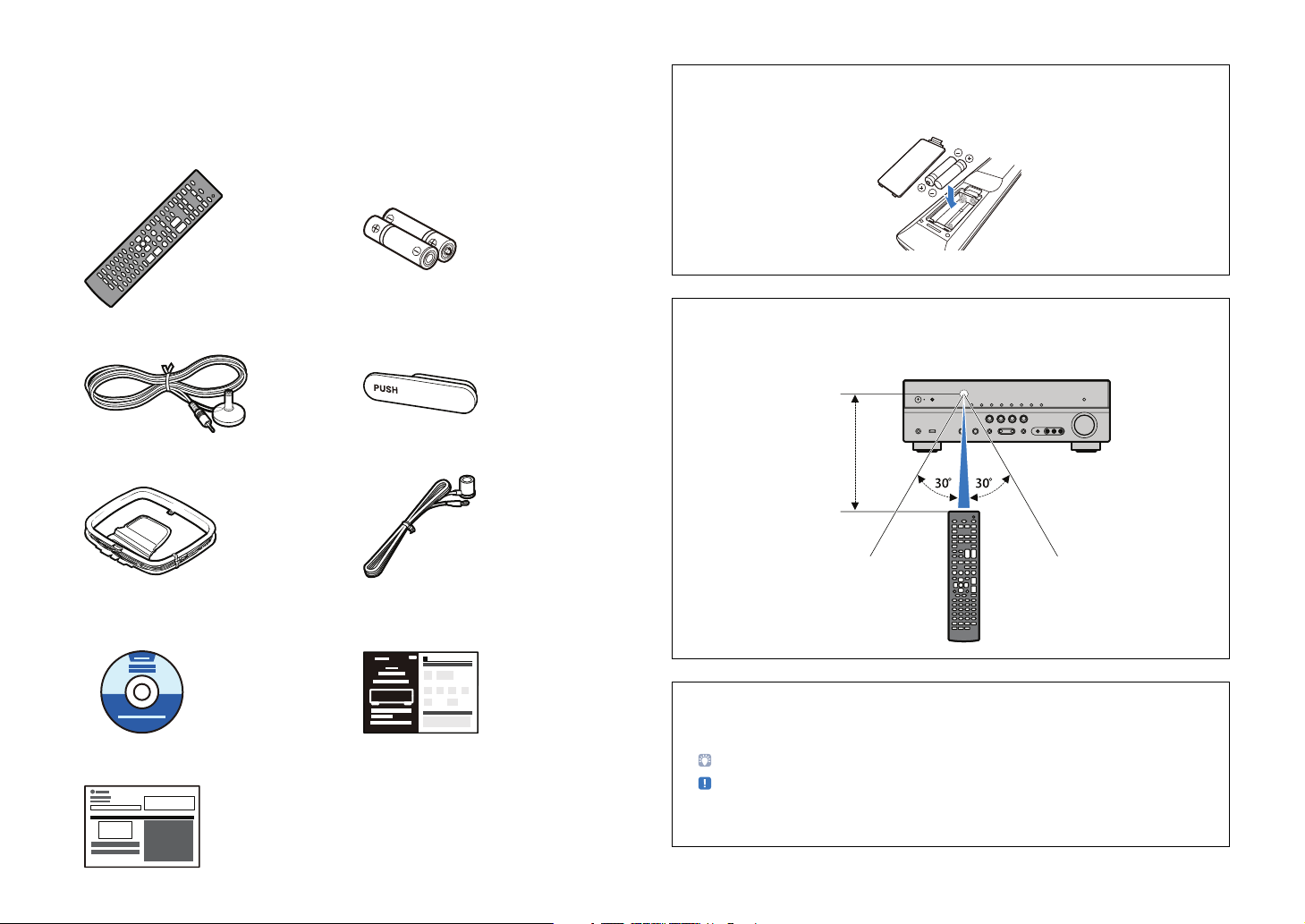
Check the supplied items
Check that the following accessories are supplied with this product.
■ Remote Control ■ Batteries (AAA, R03, UM-4) (x 2)
Preparing the remote control
• Insert the two supplied AAA batteries into the battery case, following the polarity markings (+ and -).
■ YPAO microphone ■ VIDEO AUX input cover
■ AM antenna ■ FM antenna
* The supplied FM antenna will differ depending
on the country or region.
■ CD-ROM (Owner’s Manual) ■ Easy Setup Guide
■ Safety Brochure
Operating range of the remote control
• Be sure to aim the remote control within the following range at the remote control sensor on the unit
during operation.
Within
6 m (20 ft.)
• This manual is created prior to production of the product. Some parts of the product and the
specifications may differ as a result of improvements, etc.
• This manual mainly explains operations using the supplied remote control.
• “ ” indicates the explanations for better use.
• “ ” indicates the cautions concerning operations or setup of the unit.
• This manual describes both the “iPod” and “iPhone” as the “iPod.” “iPod” means both “iPod” and
“iPhone” unless the explanation describes exceptions.
En 4
FEATURES
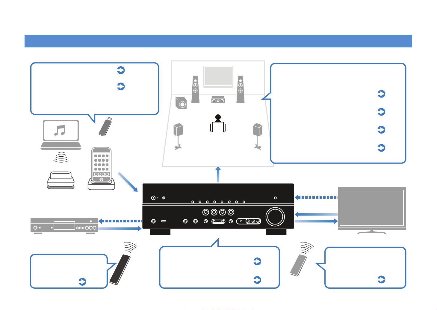
What you can do with the unit
Enjoying music stored on
p.43, 50
iPod or Bluetooth devices
Operating the iPod or USB
p.46, 52
menu (on TV)
* Requires optional Yamaha products such as iPod dock, iPod
wireless system, and Bluetooth receiver.
USB device
PC
Audio
Bluetooth receiver
(optional)
BD/DVD player
iPod dock/iPod
wireless system
(optional)
HDMI Control
Audio/Video
Speakers
Audio
AV receiver (the unit)
Supports 2 to 5.1 channel speaker system.
Allows you to enjoy favorite acoustic spaces in
various styles.
Automatically optimizing the speaker
settings to suit your room (YPAO)
p.26
Sound field reproductions like actual
movie theaters and concert halls
p.34
(CINEMA DSP)
Multi-channel playback from stereo
sounds (surround decoder)
Enjoying enhanced compression
artifacts (Compressed Music
p.36
p.37
Enhancer)
HDMI Control
Audio
Video
TV
Operating external
devices with the supplied
remote control
p.74
Remote control
of this unit
Selecting the input source and
favorite settings at once (SCENE)
Easily connecting devices such
as game console to the audio/
video jacks on the front panel
p.32
p.24
TV remote control
Operating the TV, AV
receiver and BD/DVD player
in combination
(HDMI Control)
p.87
En 5
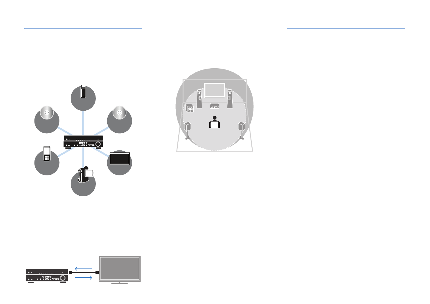
Full of useful functions!
● Connecting various devices (p.16, 21)
Various input/output jacks on the unit allow you to
connect external devices such as BD/DVD player and
CD player. The unit is also equipped with input jacks on
the front panel which allow you easily connect and enjoy
game consoles, camcorders and USB devices, and so
on.
USB
device
BD/DVD
player
Por table
audio player
Camcorder
● Playing back TV audio in surround sound
with a single HDMI cable connection (Audio
Return Channel: ARC) (p.16, 70)
When using a TV that supports ARC, you only need an
HDMI cable to connect the TV and this unit. Making
such a simple connection enables to output video to the
TV, input audio from the TV, and transmit HDMI Control
signals at once.
HDMI Control
TV audio
Video from
external device
CD
player
TV
● Creating stereoscopic sound fields (p.36)
The unit supports the surround playback of up to 5.1
channel. Various sound programs and surround
decoders equipped with the unit can supply more
intensive and accurate stereoscopic sound field in your
room. And, the unit creates virtual presence speakers to
produce 3D surround sound (CINEMA DSP 3D).
● Listening to radio with built-in receiver
(p.38)
You can register up to 40 favorite radio stations as
preset stations automatically or manually.
● Enjoying faithful sound compared to the
original source (p.37)
When the Direct mode is enabled, the unit plays back
the selected source with the least circuitry. It allows you
to enjoy the faithful sound quality compared to the
original source.
● Easy operation with a TV monitor
When connecting your TV to the unit with an HDMI
cable, the menu of the unit can be displayed on the TV
monitor to operate the unit. You can set the settings of
the unit viewing the TV monitor.
• YPAO (p.26)
• Operation menus of iPod and USB device (p.46, 52)
• The “Option” menu (p.56)
• The “Setup” menu (p.60)
At time like this
The combination of video/audio input jacks prepared on
this unit does not match an external device...
Use “Audio In” in the “Option” menu to change the
combination of video/audio input jacks so that it matches
the output jack of your external device (p.22).
I want to fine adjust sound quality...
Use “Equalizer” in the “Setup” menu to adjust sound quality
of tone with an equalizer (p.63).
Video and audio are not synchronized...
Use “Lipsync” in the “Setup” menu to adjust the delay
between video and audio output (p.64).
I want to hear audio from the TV speakers...
Use “Audio Output” in the “Setup” menu to redirect the
output audio signal to the TV (p.70).
I want to prevent forgetting to turn the unit off...
Use “Auto Power Down” in the “Setup” menu to prevent
forgetting to turn the unit off (p.68).
I want to play back BD/DVD player without the unit
turned on...
Use “Standby Through” in the “Setup” menu to play back
BD/DVD player while the unit keeps to be turned off (p.71).
There are many other functions to customize or confirm
the settings of this unit.
For details, see the following pages.
• SCENE settings (p.32)
• Sound program and surround decoder settings (p.65)
• Various function settings (p.68)
• Current signal information (audio signal, video signal)
(p.58)
• Basic settings before use (p.72)
En 6
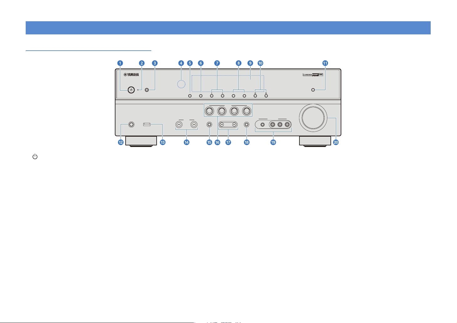
Part names and functions
Front panel
ATURAL SO ND AV RECEIVER RX-V471
1 (power) key
Turns the unit on or into the standby mode.
2 Standby indicator
When the unit is in standby mode, lights up in any of the
following cases when:
- The “Standby Through” function is working (p.71).
- The iPod is charging with “Standby Charge” (p.58).
- The Yamaha iPod wireless system is connected (p.45).
3 YPAO MIC jack
For connecting the supplied YPAO microphone (p.26).
4 Remote control receiver
Receives signals from remote control (p.4).
5 INFO
Changes the information displayed on the front display
(p.31).
6 MEMORY
Registers FM/AM stations as preset stations (p.39).
7 PRESET
Selects the FM/AM preset stations (p.39).
8 FM/AM
Switches FM/AM tuner band to FM or AM (p.38).
PHONES
SILENT CINEMA
YPAO MC
USB
iPod/Phone
NFO MEMORY PRESET
NPUT
BD
DVD
TV CD RADIO
PROGRAM
AM TUNING
FM
SCENE
STRAGHTTONE CONTROL
VIDEO AUX
PORTABLE
9 Front display
Displays information about the unit (p.8).
0 TUNING
Changes FM/AM tuner frequency (p.38).
a DIRECT
Enables/disables the direct mode (p.37).
b PHONES jack
For connecting headphones.
c USB port
For connecting USB devices (p.52).
d INPUT
Switches the selected input source.
e TONE CONTROL
Adjusts high-frequency/low-frequency output of speakers
and headphones (p.57).
f SCENE
Selects the input source and the sound programs with a
single button. When the unit is in standby mode, press this
key to turn on the unit (p.32).
DIRECT
VOLUME
VIDEO
L AUDO R
g PROGRAM
Selects a sound program and surround decoder (p.33).
h STRAIGHT
Enables/disables the straight decoding mode (p.37).
i VIDEO AUX jack
For connecting camcorders, game consoles, etc (p.24).
Attach the supplied VIDEO AUX input cover (p.4) when not
using this jack to protect against dust.
j VOLU ME
Adjusts the volume level.
En 7
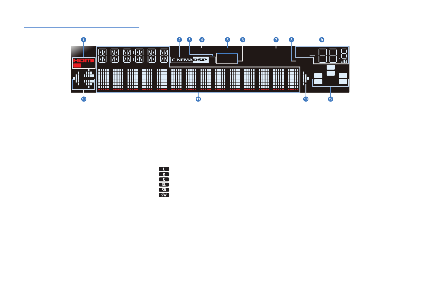
Front display (indicator)
OUT
1 HDMI
Lights up when an HDMI device is connected to the unit or
an HDMI signal is being output.
OUT
Lights up when HDMI signals are output.
2 CINEMA DSP
Lights up when a sound program with CINEMA DSP is
activated.
3 CINEMA DSP 3D
Lights up when CINEMA DSP 3D (p.36) is activated.
4 ENHANCER
Lights up when the Compressed Music Enhancer (p.37) is
activated.
5 ADAPTIVE DRC
Lights up when Adaptive DRC (p.57) is activated.
6 STEREO
Lights up when stereo broadcasting is input.
TUNED
Lights up when an FM/AM station is received.
7 SLEEP
Lights up when the sleep timer is on (p.31).
8 MUTE
Flashes when audio is muted.
9 VOLU ME
Displays the current volume level.
ENHANCER ADAPTIVE DRC
STEREO
3
TUNED
0 Cursor indicators
Lights up the available cursors on the remote control for each
operation.
a Multi information display
Displays a range of information.
Press INFO on the remote control or front panel repeatedly to
cycle through displayed information (p.31).
b Speaker indicators
Displays speaker terminals from which signals are output.
Front speaker L
Front speaker R
Center speaker
Surround speaker L
Surround speaker R
Subwoofer
SLEEP
VOL.
MUTE
SW
C
LR
SL SR
En 8
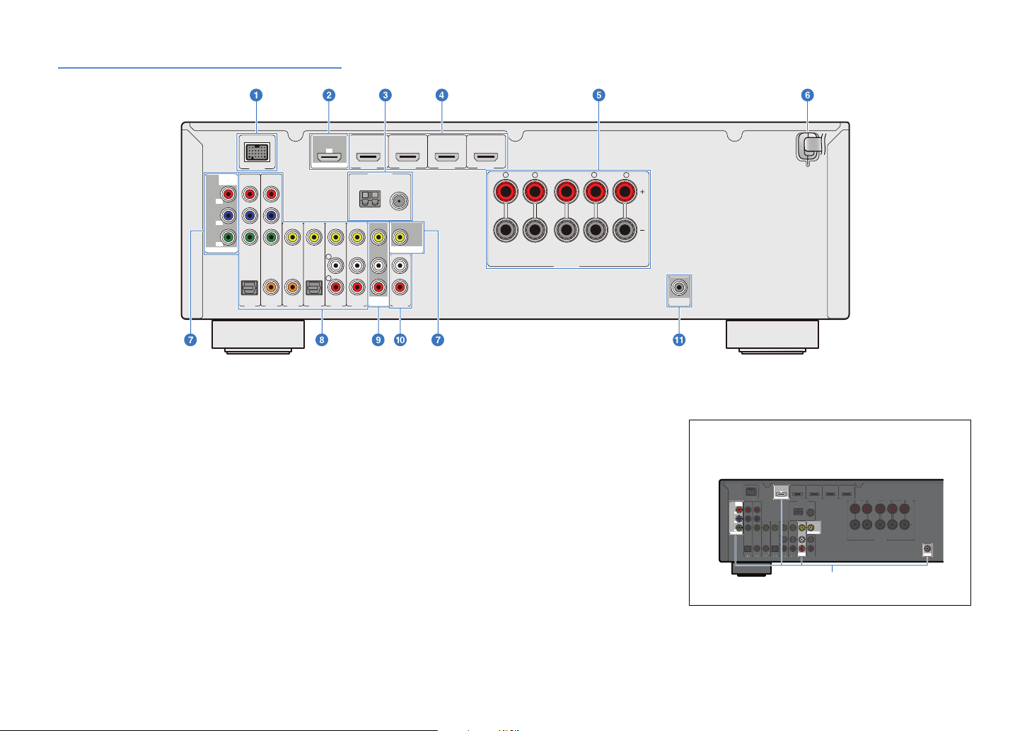
Rear panel
DOCK
(
)
3
5Ω
AM
FM
O
O
V 5
V 6
UDO
C
)
H
4
R
SRRO
S
DOCK
COMPONENT
V DEO
P
R
P
B
Y
MONITOR OUT
OPTICAL
VIDEO
COAX AL COAXIAL
AV 1
(CD) (TV)
AV 2 AV 3 AV 4 AV 5 AV 6
1 DOCK jack
For connecting an optional Yamaha iPod universal dock,
Wireless System for iPod and Bluetooth wireless audio
receiver (p.44, 45, 50).
2 HDMI OUT jack
For connecting a TV that is compatible with HDMI input to
output audio/video signals. TV audio is input when ARC is
used (p.16, 18, 19).
3 ANTENNA jacks
For connecting AM and FM antennas (p.24).
4 HDMI 1-4 jacks
For connecting external devices that are compatible with
HDMI outputs to receive audio/video signals (p.21).
5 SPEAKERS terminals
For connecting speakers (p.14).
6 Power cable
For connecting the unit to an AC wall outlet (p.25).
OPTICAL
ARC
HDMI OUT
L
R
(BD DVD)
HDMI 1
HDMI 2
HDMI 3
ANTENNA
AM FM
AV
OUT
75Ω
MONITOR OUT
AUDO
HDMI 4
FRONT CENTER SURROUND
R
L
SPEAKERS
7 MONITOR OUT jacks
COMPONENT VIDEO jacks
For connecting a TV that is compatible with component video
signals and outputting video signals (p.20).
VIDEO jack
For connecting a TV that is compatible with video signals to
output video signals (p.20).
8 AV1-6 jacks
For connecting to playback devices equipped with audio/
video outputs to receive audio/video signals (p.21).
9 AV OUT jacks
For outputting received audio/video signals when analog
inputs (AV5-6 or AUDIO) are selected (p.25).
0 AUDIO jacks
For connecting to playback devices equipped with analog
audio outputs to input audio signals (p.23).
MAINS
R
L
SUBWOOFER
(U.K. and Europe models)
a SUBWOOFER jack
For connecting a subwoofer with a built-in amplifier (p.14).
The area around the audio/video output jacks is marked in
white. Use these jacks to output audio/video signals to a TV
or other external device.
C
(B /D D)
B /D D
HDMI OUT
DOCK
OM O E T
VD O
P
R
P
Y
MONTOR OU
O T AL
T AL
I EO
I E
CO X L OXAL
O T C L
O XLO X AL
O T C L
(C )
(C
V 5 V 6
HDM 1
HDMI 2 HDM 3
ANTENN
ANTENN
AM FM
5Ω
MONTOR O T
AV
UDO
Output jacks
HDM
HDMI 4
DMI
RONT CNTER S RROUN
RONTCNTE
UN
S EAKER
EAKER
S BW OE
En 9
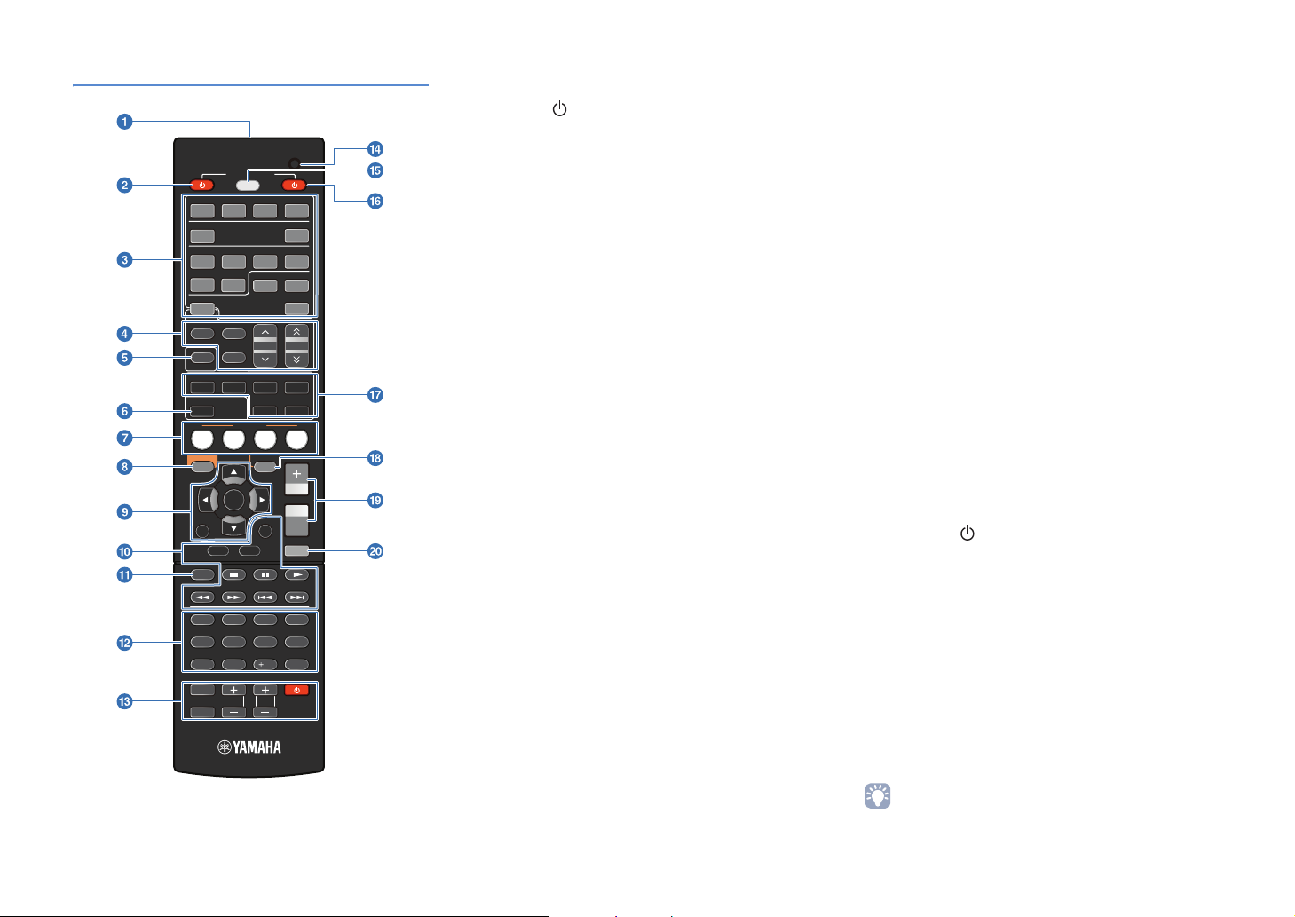
Remote control
1 2 3 4
[ A ]
1 2 3
5
TUNER
FM
INFO
MOVIE MUSIC
SLEEP DIRECT
BD
DVD
SETUP
RETURN
TOP
MENU
MODE
1234
56 87
9 0
INPUT
MUTE
RECEIVER
SOURCE
HDMI
AV
6
AUDIO
AM
PRESET
MEMORY
SUR. DECODE
ENHANCER
SCENE
TV
OPT ON
ENTER
DISPLAY
TV
TV VOL TV CH
CD
POP UP
MENU
10
CODE SET
V AU X
4
DOCK
USB
TUN NG
STRA GHT
RADIO
VOLUME
MUTE
ENT
1 Remote control signal transmitter
Transmits infrared signals.
2 SOURCE (source power)
Switches an external device on and off.
3 Input selection keys
Select an input source on the unit to play back.
HDMI 1-4 HDMI 1-4 jacks
V-A UX VIDEO AUX jack on the front panel
AV 1 - 6 AV 1-6 jacks
AUDIO Audio jack
DOCK A Yamaha iPod universal dock, iPod
wireless receiver, and Bluetooth
wireless receiver that are connected to
the DOCK jack.
TUNER FM/AM tuner
USB USB devices connected the USB jack.
[A] Switches an external device that can
be operated with the External device
operation keys without changing inputs
(p.75).
4 Radio keys
Operate the FM/AM tuner.
FM Sets the FM/AM tuner band to FM.
AM Sets the FM/AM tuner band to AM.
MEMORY Presets radio stations.
PRESET Selects a preset station.
TUNING Changes tuning frequencies.
5 INFO
Switches the information displayed on the front display
(p.31).
6 SLEEP
Selects the time of sleep timer (120 min., 90 min., 60 min.,
30 min., and Off) by pressing this key repeatedly. SLEEP
indicator lights up on the front display while using the sleep
timer. After the selected time passes, the unit switches into
the standby mode.
7 SCENE
Switch the input source and the sound program with a single
button. When the unit is in standby mode, pressing this key
turns on the unit (p.32).
8 SETUP
Displays/finishes the “Setup” menu for the unit (p.60).
9 Menu operation keys
Cursor keys Select menu items and settings.
ENTER Confirms a selected item.
RETURN Returns to the previous screen when
the menu is displayed.
0 External device operation keys
Operate recording, playback, menu displays, etc. for
external devices (p.75, 76).
a MODE
Switches the FM broadcast receiving modes (p.38) or the
iPod operation modes (p.49).
b Numeric keys
Enter numbers such as the frequency of FM/AM tuner and
remote control codes.
c TV control keys
Controls TV operation, such as input and volume level
(p.74, 75).
d CODE SET
Sets remote control codes for external devices (p.74).
e SOURCE/RECEIVER
Switches the device (external device or the unit) that is available
with remote control keys. Lights up in orange when the unit is
selected, in green when an external device is selected.
f RECEIVER (receiver power)
Switches the unit between on and standby mode.
g Sound selection keys
Switches between the sound field effect (sound program)
you are using and the surround decoder (p.33).
h OPTION
Displays/finishes the “Option” menu for each input source
(p.56).
i VOLU ME
Adjusts the volume balance (p.31).
j MUTE
Turns the mute function on and off (p.31).
• Remote control codes need to be registered in advance to operate
external devices with this remote control. If you use HDMI
compatible devices, remote control might be available only by
connecting them (p.87).
En 10

SETUP
General setup procedure
Perform the following 8 steps before use.
1 Speaker layout (p.12)
2 Connecting speakers (p.14)
3 Connecting a TV (p.16)
4 Connecting playback devices (p.21)
5 Connecting the FM/AM antennas (p.24)
6 Connecting recording devices (p.25)
7 Connecting the power cable (p.25)
Optimizing the speaker settings automatically
8
(YPAO) (p.26)
All settings needed before use are completed here. Enjoy playing movies, music, radio, etc. with the unit!
Select the speaker layout depending on the number of speakers, and then place the speakers in
the room.
Connect each speaker to the unit.
Connect TV to the unit.
Connect video devices (BD/DVD players, etc.) or audio devices (CD players, etc.) to the unit.
Connect the FM/AM antennas to the unit.
Connect external devices such as recording devices.
After all the settings above are complete, plug in the power cable.
Adjust the volume balance and tone of speakers automatically (YPAO).
En 11
Speaker layout
1
2 3 4 5 6 7 8
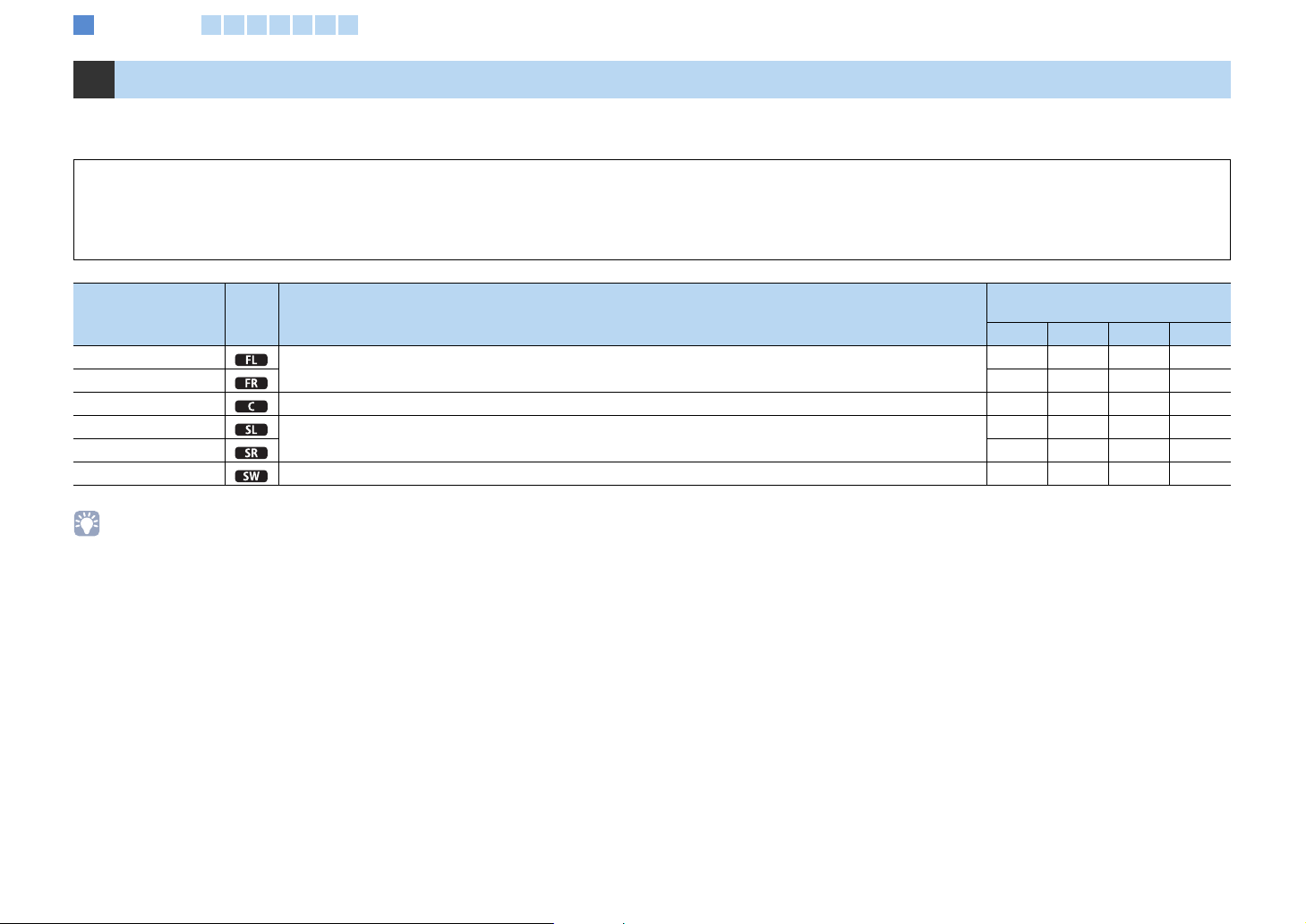
1 Speaker layout
Select the speaker layout depending on the numbers of speakers, and then place the speakers and subwoofer (with a built-in amplifier) in the room.
The following section describes the representative speaker configuration of 2.1 to 5.1 channel system.
NOTES
• (U.S.A. and Canada models only) The unit is configured to 8Ω speakers as the factory setting. 6Ω speakers can be also connected. For details on settings for 6Ω speaker connection, refer to “Changing the speaker
impedance (U.S.A. and Canada models only)” (p.72).
• (Except for U.S.A. and Canada models) Use speakers with an impedance of at least 6Ω.
Speaker system
Type of speakers Abbr. Function
Front (L)
Front (R) ●●●●
Center For the center channel sound (dialogue, vocals, etc.) ●●
Surround (L)
Surround (R) ●●
Subwoofer For low-frequency effect (LFE) sound and bass sound from front and surround channels. ●●●●
For the front channel sound (stereo sound) and effect sound
For effect and vocal sound from surround channel. The surround back channel sound is output from the surround speakers
when 7.1- or 6.1-channel sounds are input.
(the number of channels)
5.1 4.1 3.1 2.1
●●●●
●●
• To get recommended speaker layout, refer to “Ideal speaker layout” (p.83).
En 12
Speaker layout
1
2 3 4 5 6 7 8
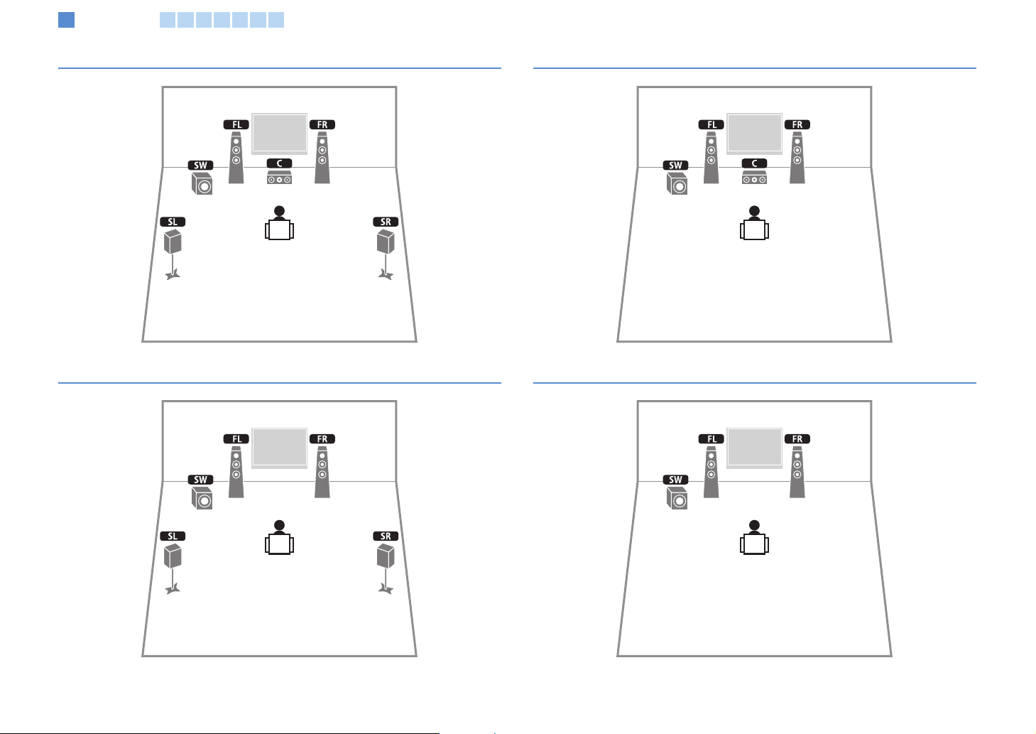
5.1-channel speaker layout
4.1-channel speaker layout
3.1-channel speaker layout
2.1-channel speaker layout
En 13
FRONT
FRONT
Connecting speakers
1 2
3 4 5 6 7 8
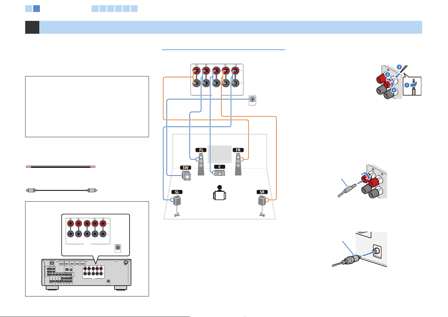
2 Connecting speakers
Connect speakers to the unit. Here are connections of
5.1-channel speaker layout as examples. If you select
another channel speaker layout, connect speakers while
referring to the connection of 5.1-channel speaker
layout.
NOTES
• Disconnect the power plug before connecting speakers.
• Before connecting a subwoofer, turn off a subwoofer.
• Be careful that the core of the speaker cable does not touch
anything or come into contact with the metal areas of the unit.
This may damage the unit or the speakers. If the speaker cables
short circuit, “CHECK SP WIRES!” will appear on the front
display when the unit is switched on.
Necessary cables (not supplied)
Speaker cables x numbers of speakers
+
–
+
–
Monaural pin cable (for subwoofer) x 1
Speaker terminals on the rear of the unit
FRONT CENTER SURROUND
SPEAKERS
C
B/ V )
H MI UT
D CK
D I
DM 2 HDI
DM
P AL
C A O L
A 1
V V AV V 5 V
ATE NA
AM M
P C L
D) ( )
OT
CM O N
V EO
P
P
Y
FONT CN ER S R OU D
5Ω
U O
PAK R
SB OF
SU WO FER
5.1-channel speaker layout
The unit (rear)
FRONT CENTER SURROUND
R
L
■ Connecting speaker cables
Each speaker has two speaker cables. One is for
connecting the - (negative) terminal of the unit and the
speaker, and the other is for the + (positive) terminal.
The cables are different colors, so they do not get mixed
up. Connect the black side to the - (negative) terminal
and the other side to the + (positive) terminal.
SPEAKERS
R
L
SUBWOOFER
1 Remove approximately 10 mm (0.4 in.) of insulation
from the end of the speaker cable and twist the bare
wire firmly.
2 Loosen the speaker
terminal.
+ (Red)
3 Insert the bare wire
into the gap on the
side of terminal.
When it is difficult to
- (Black)
insert the wire into the
gap on the side,
insert it into the gap downside of terminal.
4 Tighten the terminal.
Connecting with a banana plug (Except for U.K. and
Europe models)
Tighten the knob, and then insert a banana plug into the
end of the terminal.
Banana plug
■ Connecting a subwoofer
Use monaural pin cable to connect a subwoofer.
Before connecting a subwoofer, turn off the subwoofer.
Monaural pin cable
En 14
Cable plugs and jacks
The unit is equipped with the following input/output jacks. Use jacks and cables appropriate for devices.
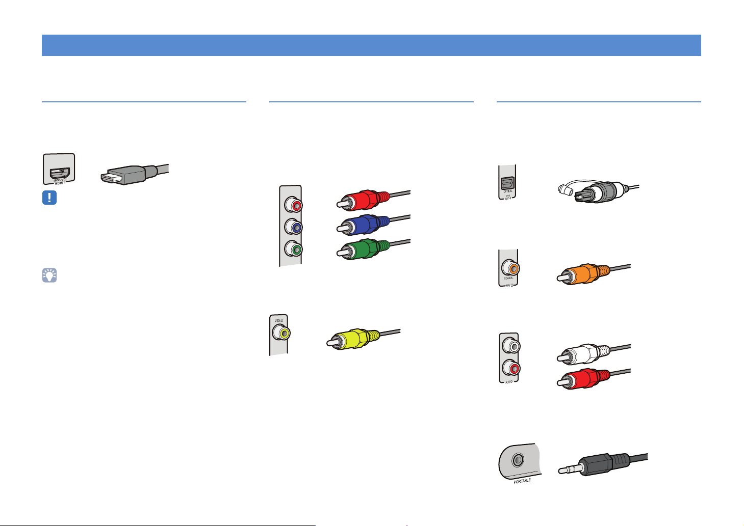
Audio/video jacks
HDMI jacks
Digital videos and sounds are transmitted. Use an HDMI
cable for connection.
HDMI cable
• Use a 19-pin HDMI cable with the HDMI logo. Using an HDMI cable
less than 5.0 m (16.4 ft.) long is recommended to prevent signal
quality degradation.
• When connecting an external device with a DVI jack, use an HDMI/
DVI -D cab le .
• The HDMI control function, the Audio Return Channel function and
transmission of 3D content are supported.
Analog video jacks
COMPONENT VIDEO jacks
The signal is separated into three devices:
Luminance (Y), chrominance blue (PB) and
chrominance red (PR).
Use a component video pin cable with three plugs.
Component video cables
Red
P
R
P
B
Y
VIDEO jack
This jack transmits conventional analog video signal.
Use a video pin cable.
Video pin cable
Blue
Green
Audio jacks
OPTICAL jacks
These jacks transmit optical digital audio signals. Use
fiber-optic cables for connection. Remove the cap
before using if needed.
Digital optical cable
COAXIAL jacks
These jacks transmit coaxial digital audio signals. Use
coaxial cables.
Digital coaxial cable
AUDIO jacks
These jacks transmit conventional analog audio signals.
Use stereo pin cables.
Stereo pin cable
PORTABLE jack
This jack transmits conventional analog audio signals.
Use a stereo mini-plug cable when connecting.
Stereo mini-plug cable
En 15
M
O
1 2 3
Connecting a TV
4 5 6 7 8
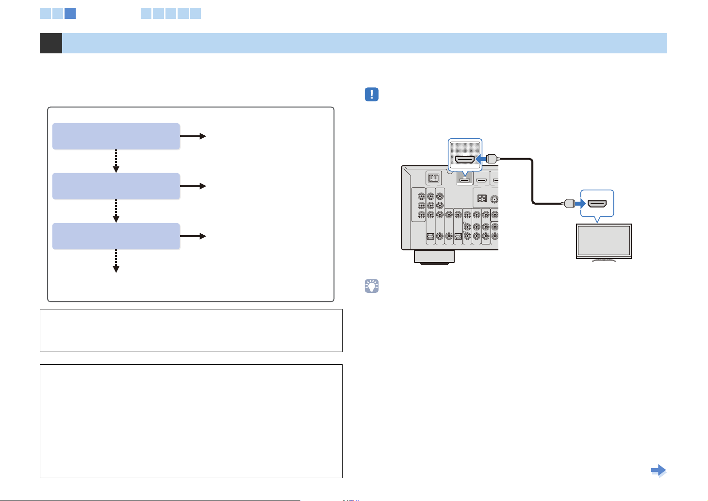
3 Connecting a TV
Connect a TV to the unit. The video signals input to the unit are output to the TV.
TV audio can also be output from the unit. The recommended way to connect a TV
varies depending on types and functions of video input jacks on the TV.
Select how to connect the TV to the unit while referring to the TV manual.
Does you TV support
Audio Return Channel (ARC)?
No
Does you TV support
HDMI Control?
No
Does your TV have an
HDMI input jack?
No
■ Connection method 4 (p.20)
HDMI, component video, or composite video signal input to the unit is output from
the same type of output jack (p.86). Make necessary connections, and switch the
input source on TV depending on the playback device.
What is the HDMI control function?
By connecting a TV to the unit with an HDMI cable, some operations for the unit are
available with the TV’s remote control, such as turning on/standby and volume
control. If playback devices that support the HDMI control function (BD/DVD
players, etc.) are connected to the unit, these are also acceptable. For more details,
refer to “HDMI Control” (p.87).
What is the Audio Return Channel (ARC)?
If your TV supports the ARC, TV audio can be output to the unit by using an HDMI
cable transmitting video signals from the unit to a TV.
Yes
■ Connection method 1 (on this page)
and
■ Connection method 4 (p.20)*
Yes
■ Connection method 2 (p.18)
and
■ Connection method 4 (p.20)*
Yes
■ Connection method 3 (p.19)
and
■ Connection method 4 (p.20)*
* Necessary if your playback device is connected to the
video input jacks other than HDMI1-4 jacks.
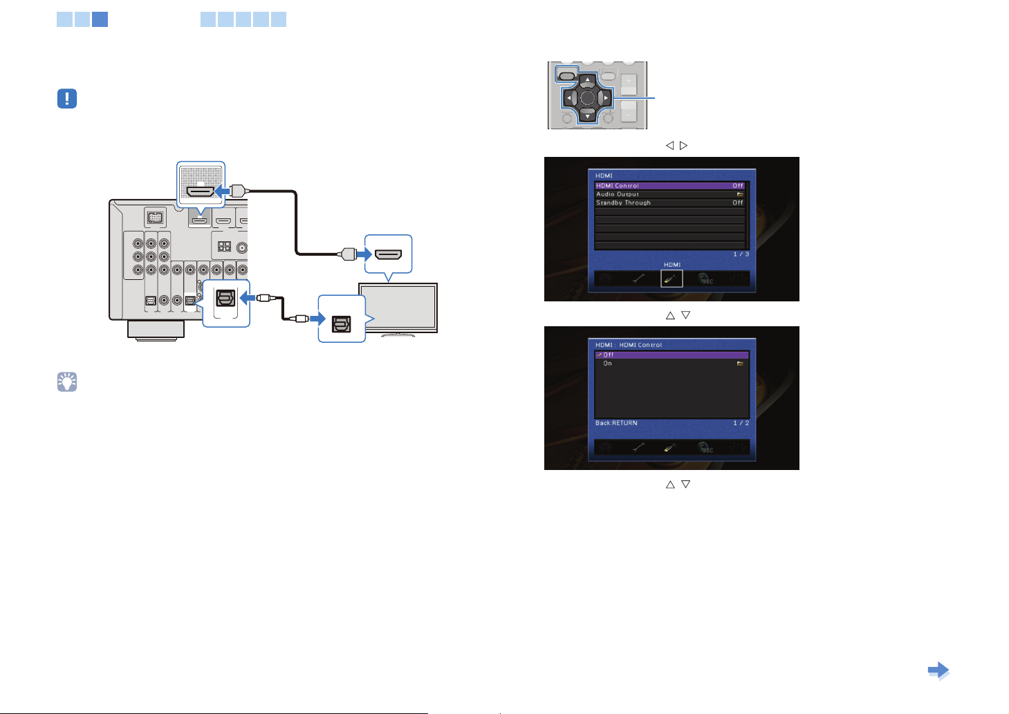
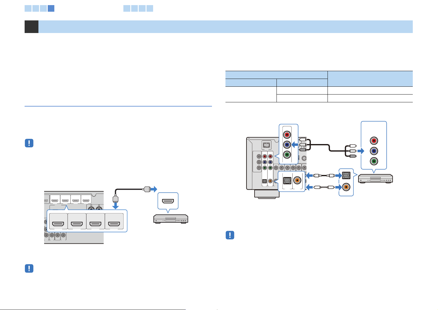
■ Connection method 1
(ARC-compatible TV)
Connect a TV to the unit with an HDMI cable.
• The following connections and steps are supplied, supposing that “HDMI” in the “Setup” menu has not been
changed from the default setting (p.69).
HDMI OUT jack
ARC
HDMI OUT
HDMI
A C
BD/DVD)
HDMI 1
HD
ANTENNA
AM FM
75Ω
MONT
L
R
AV
OUT
AUDIO
HDMI
HDMI input
ARC
HDMI
The unit (rear)
DOCK
OMPON NT
VI EO
PR
PB
Y
MONITOR OUT
OPTCAL
AV 1
HDMI OUT
VDEO
OAXAL COA IAL
O T CAL
(CD) TV)
AV 2 AV 3 AV 4 AV 5 AV 6
TV
• By connecting a TV to the unit with an HDMI cable, each function for the unit can be configured while
viewing the TV monitor (p.60).
• If your playback device is connected to the analog video input jacks (COMPONENT VIDEO or VIDEO), you
also need to connect the TV to the MONITOR OUT (COMPONENT VIDEO or VIDEO) jack with an analog
video cable (p.20).
Necessary settings
To use the HDMI control function and ARC, the following settings are required in
advance.
1 After connecting external devices (TV, playback devices, etc.) and AC
power cable, turn on the unit, TV and playback devices.
Continues to the
next page
En 16
RETUR
D SP
1 2 3
Connecting a TV
4 5 6 7 8
2 Configure the settings for ARC.
a Confirm that the ARC function for the TV is set to on.
For details on how to confirm, refer to manual of the TV.
b Select the input source of the TV to the video input from the HDMI OUT jack of the
unit.
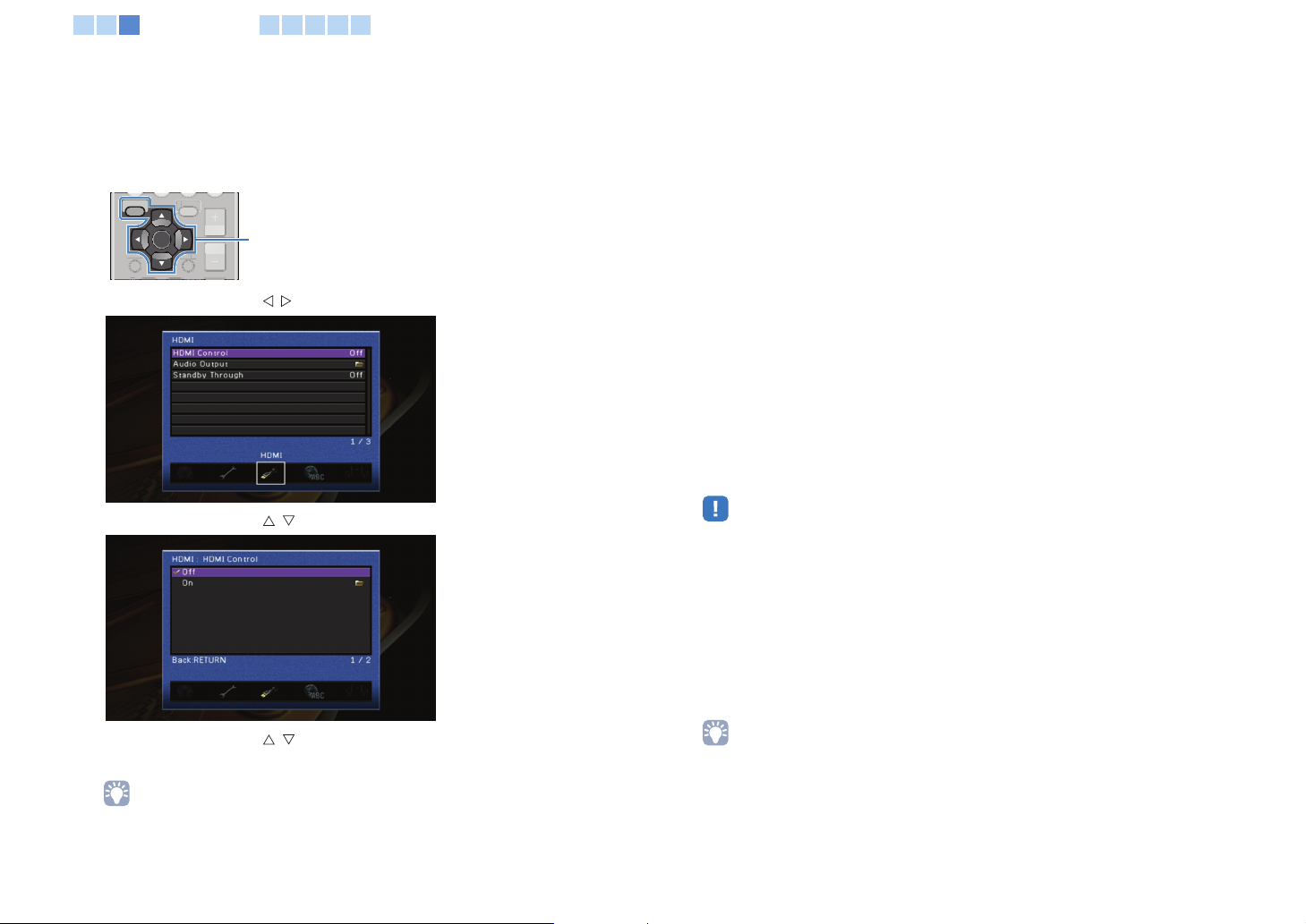
c Press SETUP.
OPTION
OPTION
SETUP
ENTER
RETUR
D SP A
d Press the cursor keys ( / ) to select “HDMI.”
e Press the cursor keys ( / ) to select “HDMI Control,” and then press ENTER.
SETUP
Cursor keys
ENTER
3 Configure the settings for HDMI Control.
a Activate the HDMI control function of the TV and the devices that support the HDMI
control function.
For details on setting the HDMI control function, refer to the manual of each device.
b Turn off the TV.
The unit and devices are also turned off automatically with the TV’s operation. If they
do not turn off, turn them off manually.
c Turn on the TV.
The unit also turns on with the TV. If the unit does not turn on, turn it on manually.
d Change input video source on the TV to video signals from the unit.
e Turn on the playback devices, and then confirm the following:
Unit: Whether the input signals from the playback devices are selected as the HDMI
input source (any of “HDMI 1-4”). When it is not selected, select the correct input
source manually.
TV: Whether the video signals from the playback devices are displayed on the TV
screen.
f Confirm whether the unit is linked with operations of the TV remote control as follows:
Turning on/standby, volume control and selecting audio output devices.
If these operations are not available, check that “HDMI Control” (p.69) in the “Setup”
menu is set to “On.”
• If playing back audio source by using the ARC function has a problem, set “ARC” in the “Setup” menu
to “Off,” and connect the TV and the unit with an optical cable (p.18).
• If the HDMI control function does not work correctly, it may be effective to turn off the devices to reset
them or plug in the power cable and retry with the power cable plugged in.
• If the power-on operation is not linked, confirm the priority of audio output settings for the TV.
All settings have been completed.
When a TV program is selected with the TV remote control, input source of the unit is
switched to “AV4” automatically, and TV sound is output.
If it does not work correctly, confirm that the “ARC” in the “Setup” menu is set to “On.”
f Press the cursor keys ( / ) to select “On,” and then press ENTER.
g Confirm that “ARC” is set to “On.”
• “ARC” is set to “On” as the default setting. When “HDMI Control” is set to “On,” the ARC function of
the unit is enabled.
h Press SETUP.
• “AV4” is selected as the input sound source from a TV as the default setting. When the AV4 jack is
used for another device, select an input jack to be used for the TV audio in “TV Audio Input” on the
“Setup” menu. Also, when using the SCENE functions (p.32), register the appropriate input source on
SCENE (TV).
En 17
M
O
RETUR
D SPL
1 2 3
Connecting a TV
4 5 6 7 8
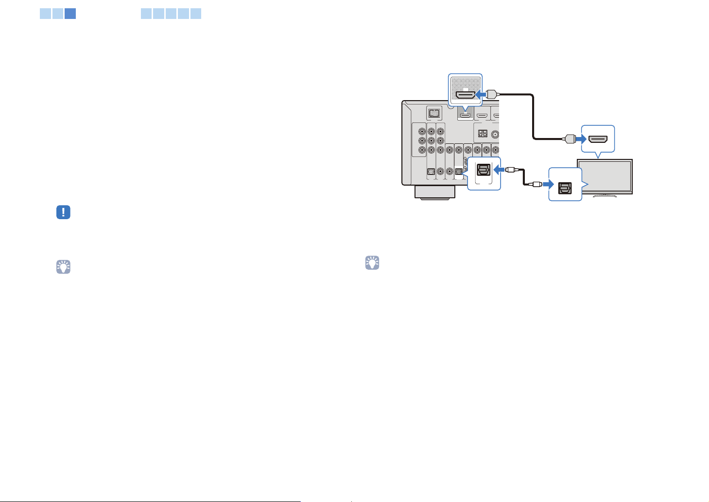
■ Connection method 2
(HDMI Control -compatible TV)
Connect a TV to the unit with an HDMI cable and an optical cable.
• The following connection and steps are supplied, supposing the “HDMI” in the “Setup” menu has not been
changed from the default setting (p.69).
HDMI OUT jack
ARC
The unit (rear)
DOCK
COM ONEN
VDEO
PR
PB
Y
MONTOR OUT
O T CAL
AV 1
HDMI OUT
IDEO
COA IAL OAXAL
OPTCAL
CD)
(TV)
AV 2 AV 3 A
AV 4
HDMI
ARC
(BDDVD)
HDMI OUT
HDMI 1
HD
ANTENNA
AM FM
5Ω
MONIT
O
OPTICAL
(TV)
AV 4
AV4 (OPTICAL) jack
HDMI
OPTICAL
O
Audio output
(Digital optical)
HDMI input
HDMI
TV
• By connecting a TV to the unit with an HDMI cable, each function for the unit can be configured while
viewing the TV monitor (p.60).
• If your playback device is connected to the analog video input jacks (COMPONENT VIDEO or VIDEO), you
also need to connect the TV to the MONITOR OUT (COMPONENT VIDEO or VIDEO) jack with an analog
video cable (p.20).
Necessary setting
To use the HDMI control function, the following settings are required in advance.
1 After connecting external devices (TV, playback devices, etc.) and AC
power cable, turn on the unit, TV and playback devices.
2 Configure the settings for HDMI Control.
a Activate the HDMI control function of the TV and the devices that support the HDMI
control function.
For details on setting the HDMI control function, refer to manual of each device.
b Select the input source of the TV to the video input from the HDMI OUT jack of the
unit.
c Press SETUP.
OPTION
OPTION
SETUP
SETUP
Cursor keys
ENTER
RETUR
ENTER
D SPLAY
d Press the cursor keys ( / ) to select “HDMI.”
e Press the cursor keys ( / ) to select “HDMI Control,” and then press ENTER.
f Press the cursor keys ( / ) to select “On,” and then press ENTER.
g Press SETUP.
h Turn off the TV.
The unit and devices are also turned off automatically with the TV’s operation. If they
do not turn off, turn them off manually.
i Turn on the TV.
The unit also turns on. If the unit does not turn on, turn it on manually.
j Change input video source on the TV to video signals from the unit.
Continues to the
next page
En 18
M
O
1 2 3
Connecting a TV
4 5 6 7 8
k Turn on the playback devices, and then confirm the following:
Unit: Whether the input signals from the playback devices are selected as the HDMI
input source (any of “HDMI 1-4”). When it is not selected, select the correct input
source manually.
TV: Whether the video signals from the playback devices are displayed on the TV
screen.
l Confirm whether the unit is linked with operations of the TV remote control as follows:
Turning on/standby, volume control and selecting audio output devices.
If these operations are not available, confirm that “HDMI Control” in the “Setup” menu
is set to “On.”
All settings have been completed.
When a TV program is selected with the TV’s remote control, the input source of the
unit is switched to “AV4” automatically, and TV sound is output.
When these operations are not linked, confirm that “HDMI Control” in the “Setup”
menu is set to “On.”
• When the HDMI control function does not work correctly, it may be effective to turn off the devices to
reset or plug in the power cable and retry with the power cable plugged in.
• If the power-on operation is not linked, confirm the priority of audio output settings for the TV.
• “AV4” is selected as input sound source from a TV as the default setting. When the AV4 jack is used
for another device, select an input jack to be used for the TV audio in “TV Audio Input” of the “Setup”
menu. Also, when using the SCENE functions (p.32), register the appropriate input source for SCENE
(TV).
■ Connection method 3
(TV with HDMI input jacks)
Connect a TV to the unit with an HDMI cable and an optical cable.
HDMI OUT jack
The unit (rear)
DOCK
OMPON NT
VI EO
PR
PB
Y
MONITOR OUT
OPTCAL
AV 1
ARC
HDMI OUT
A C
HDMI OUT
VDEO
L
R
OAXAL COA IAL
O T CAL
(CD)
TV)
AV 2 AV 3 A
AV 4
AV4 (O P TI C AL ) ja ck
BD/DVD)
HDMI 1
OPTICAL
ANTENNA
AM FM
(TV)
AV 4
HDMI
HDMI
HDMI input
HDMI
TV
HD
75Ω
MONT
O
OPTICAL
O
Audio output
(Digital optical)
By switching input source into “AV4” with AV4 key on the remote control or SCENE. TV
sound is output from the unit.
• By connecting a TV to the unit with an HDMI cable, each function for the unit can be configured while
viewing the TV monitor (p.60).
• If your playback device is connected to the analog video input jacks (COMPONENT VIDEO or VIDEO), you
also need to connect the TV to the MONITOR OUT (COMPONENT VIDEO or VIDEO) jack with an analog
video cable (p.20).
• When the AV4 jack is used for another device, or another terminal, except when an OPTICAL jack (with an
optical cable) is used for inputting TV sound, select another jack (any of AV 1-6 or AUDIO) for the
connection. Also, set the input sources setting of SCENE (TV) (p.32).
En 19
O
1 2 3
Connecting a TV
4 5 6 7 8
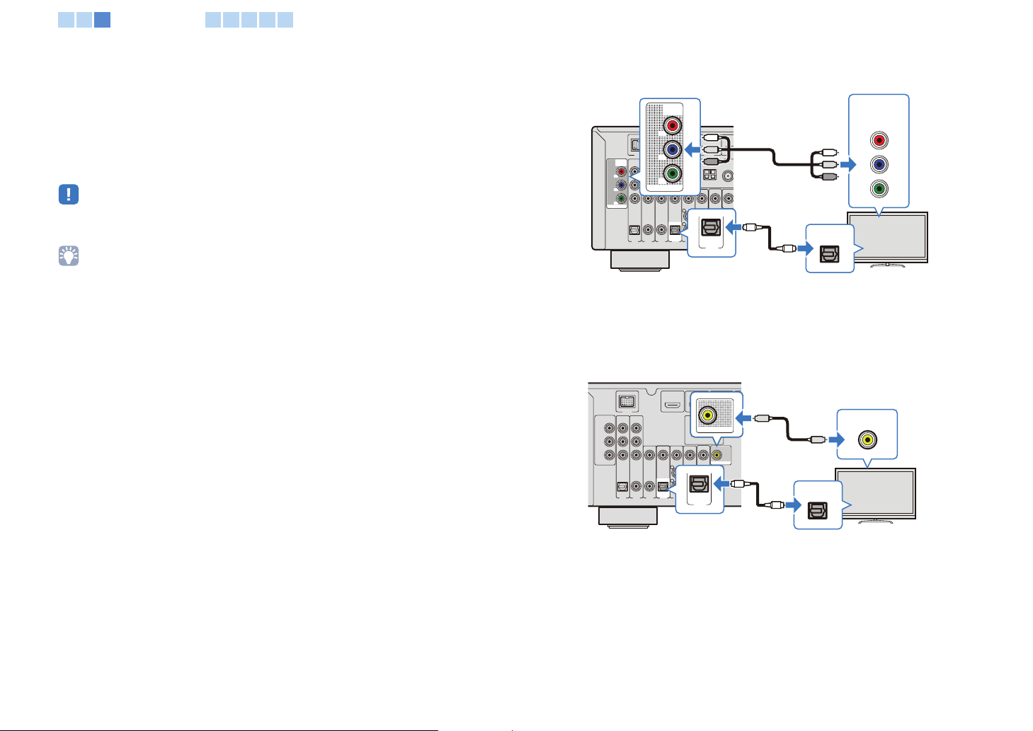
■ Connection method 4
The video signals input from the playback device to the analog video input jacks
(COMPONENT VIDEO or VIDEO) are output from the same type of the MONITOR OUT
jack to the TV.
Connect the TV to the MONITOR OUT jack of the same type as the analog video input
jacks connected to the playback device, depending on the input jack on the TV.
By switching the input source to “AV4” with AV4 on the remote control or SCENE (TV),
TV sound is output from the unit.
• When connecting to a TV with a cable, other than an HDMI cable, operations with TV screen (such as the
setting of the unit, operations of iPod/USB devices) are not available.
• When the AV4 jack is used for another device, or another terminal, except for an OPTICAL jack (with an
optical cable), is used for inputting TV sound, select another jack (any of AV1-6 or AUDIO) for the
connection. Also, set the input sources setting of SCENE (TV) (p.32).
COMPONENT VIDEO connection (with a component cable)
MONITOR OUT
(COMPONENT VIDEO) jack
COMPONENT
PR
DO
P
B
Y
MON TOR OUT
O T CAL
COA IAL OAXAL
CD)
AV 1
AV 2 AV 3 A
VIDEO
P
R
P
B
HDMI 1(D
Y
AM FM
7 Ω
MONIT
OPTCAL
OPTICAL
(TV)
AV 4
O
(TV)
AV 4
O
P
R
P
B
Y
OPTICAL
The unit (rear)
COMP NENT
VDEO
P
R
P
B
Y
MONTOR OUT
AV4 (OPTICAL) jack
Audio output
(Digital optical)
VIDEO connection (with a video pin cable)
The unit (rear)
DOCK
OMPONE T
I EO
P
R
P
B
Y
MONITOR OUT
OPTCAL
C AX AL COAXAL
AV 1
AV 2 AV 3 A
MONITOR OUT
(VIDEO) jack
A C
HDMI OUT
MONITOR OUT
VDEO
O TI AL
(CD) TV)
O TI AL
TV)
AV 4
OPT CAL
(TV)
AV 4
AV4 (OPTICAL) jack
MONTOR OUT
V
V
O
OPTICAL
O
Audio output
(Digital optical)
Video input
(Component video)
COMPONENT
VIDEO
PR
PB
Y
TV
Video input
(Analog video)
VIDEO
TV
En 20
A
O
1 2 3 4
Connecting playback devices
5 6 7 8
4 Connecting playback devices
The unit is equipped with various types of input jacks such as an HDMI jack. Connect
them to the appropriate output jacks on the playback devices.
For connecting an iPod, Bluetooth devices and USB storage devices, refer to the
following pages.
• Connecting an iPod (p.43)
• Connecting a Bluetooth wireless audio receiver (p.50)
• Connecting a USB storage device (p.52)
Connecting video devices (such as BD/DVD players)
Video devices, such as BD/DVD players, set-top boxes (STBs) and cable TV, and game
consoles, are connected to the unit. Select the correct connection according to the
output jacks (video/audio) of video devices connected to the unit. If a video device
supports HDMI, HDMI connection is recommended.
• When an input jack of the unit does not match the output jack of a video device, select another jack of the
unit for the video device (p.22).
■ HDMI connection
Connect a video device to the unit with an HDMI cable.
The unit (rear)
RC
BDDVD)
I OUT
HDMI 1
HDMI 2
ANTENNA
AM FM
I
HDMI 3
HDMI 4
FRONT
HDM
I
HDM
HDMI output
HDMI
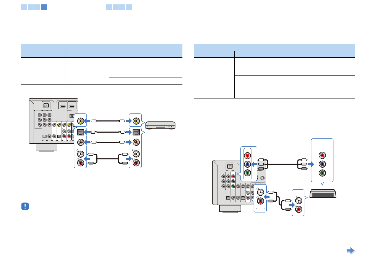
■ Component video connection
Connect a video device to the unit with a component cable and an audio cable (an
optical cable or a coaxial cable). Input jacks of the unit (AV1-2) are different depending
on the audio jacks of the video device.
Output jack of a video device
Video Audio
Component video
(COMPONENT VIDEO) jacks
The unit (rear)
DOCK
OMPONE T
VI EO
P
R
P
B
OPTCAL
AV 1
VDEO
COA IAL
OAXAL
(CD)
AV 3
AV 2
MONITOR OUT
Y
Optical AV1 (COMPONENT + OPTICAL)
Coaxial AV2 (COMPONENT + COAXIAL)
AV1-2
P
R
P
B
)
Y
E
FM
75Ω
T
O
O
OPTICAL
COAX AL
AV 1
AV 2
AV1 (OPTICAL) jack or
AV2 (COAXIAL) jack
OR
O
C
C
Input jack of the unit
Video output
(Component video)
COMPONENT
VIDEO
PR
P
R
PB
P
B
Y
Y
OPTICAL
COAXIAL
Video device
Audio output
(Digital optical or coaxial)
By selecting an input source with the AV1-2 key, audio and video from video devices are
AV 5 V 6
(BD/DVD)
HDMI 1
AV
OUT
HDMI 2
AUDO
HDMI 3
HDMI 4
HDMI 1-4 jacks
Video device
By selecting the input source with the HDMI 1-4 key, audio and video from video
devices are output from the unit.
output from the unit.
• To play back the playback device connected to the AV1-2 (COMPONENT VIDEO) jacks, it is necessary to
connect the TV to the MONITOR OUT (COMPONENT VIDEO) jacks (p.20). When playing back the device,
switch the input source on TV to the component video input connected to the unit.
• To play back the playback device connected to the HDMI1-4 jacks, it is necessary to connect the TV to the
HDMI OUT jack (p.16, 18, 19). When playing back the device, switch the input source on TV to the HDMI
input connected to the unit.
En 21
2
1 2 3 4
Connecting playback devices
5 6 7 8
■ Analog video connection
Connect video devices to the unit with a video pin cable and an audio cable (any of a
coaxial cable, an optical cable and stereo pin cable.) Input jacks of the unit (AV3-6) are
different depending on the audio input jacks of the video devices.
Output jack of video device
Video Audio
Coaxial AV3 (VIDEO + COAXIAL)
Analog video
Optical AV4 (VIDEO + OPTICAL)
Analog stereo
The unit (rear)
ARC
(BD/DVD)
COA IAL
AV 2
HDMI OUT
VDEO
OAXAL
OPTCAL
CD) (TV)
AV 3 AV 4 AV 5
HDMI 1
ANTENNA
AM
VIDEO
VV
OO
OPTICAL
A
O
AV 6
COAX AL
L
L
R
R
OR
CC
OR
MONTOR OUT
DOCK
COMP NENT
VDEO
P
R
P
B
Y
O T CAL
AV 1
AV3-6 jacks
By selecting input source with the AV3-6 key, audio and video of video devices are
output from the unit.
• To play back the playback device connected to the AV3-6 (VIDEO) jacks, it is necessary to connect the TV
to the MONITOR OUT (VIDEO) jack (p.20). When playing back the device, switch the input source on TV to
the composite video input connected to the unit.
Input jacks of the unit
AV5 (VIDEO + AUDIO)
AV6 (VIDEO + AUDIO)
Video output
(Analog video)
V DEO
OPTICAL
COAXIAL
L
L
R
R
Audio output
(any of digital optical,
coaxial, analog stereo)
Video device
■ Change the combination of input jacks (video/audio)
When an input jack of the unit does not match an output jack of a video device, select
another jack of the unit to match the jack of the video device. The Following connections
become available with this setting.
Output jacks of a video device Input jacks of the unit
Video Audio Video Audio
Optical HDMI 1-4
HDMI
Coaxial HDMI 1-4 AV2-3 (COAXIAL)
Analog stereo HDMI 1-4
Component video Analog stereo
AV1 -2
(COMPONENT VIDEO)
Necessary settings
As an example, the setting for connections, for which AV2 (COMPONENT VIDEO) jack
is used for video signals and AV5 (AUDIO) jacks are used for audio signals, is shown
below.
(COMPONENT VIDEO) jack
The unit (rear)
DOCK
OMPONE T
VI EO
P
R
P
B
Y
MONITOR OUT
OPTCAL
AV 1
AV2
IDEO
L
R
OAXAL COA IAL
O T CAL
(CD) TV)
AV 2 AV 3 AV 4 AV 6
AV 5
AV5 (AUDIO) jack
P
R
P
B
Y
)HDMI
ENNA
L
R
AV 5
P
R
P
B
Y
FM
75Ω
L
R
L
R
AUDIO
L
R
Audio output
(Analog stereo)
AV1 ( OPT ICAL )
AV4 ( OPT ICAL )
AV5-6 (AUDIO)
AUDIO
AV5-6 (AUDIO)
AUDIO
Video output
(Component video)
COMPONENT
VIDEO
PR
PB
Y
Video device
Continues to the
next page
En 22
O
1 2 3 4
Connecting playback devices
5 6 7 8
1 Complete the connections for external devices (such as a TV and
playback device), the power cable and so on, and then turn on the
unit and the TV.
2 Change the input source setting of the TV to the video from the unit.
3 Press AV2 to select “AV2” as the video input jack of the unit.
4 Press OPTION.
OPTION
Tone Control
VOL
SW
C
R
L
SL SR
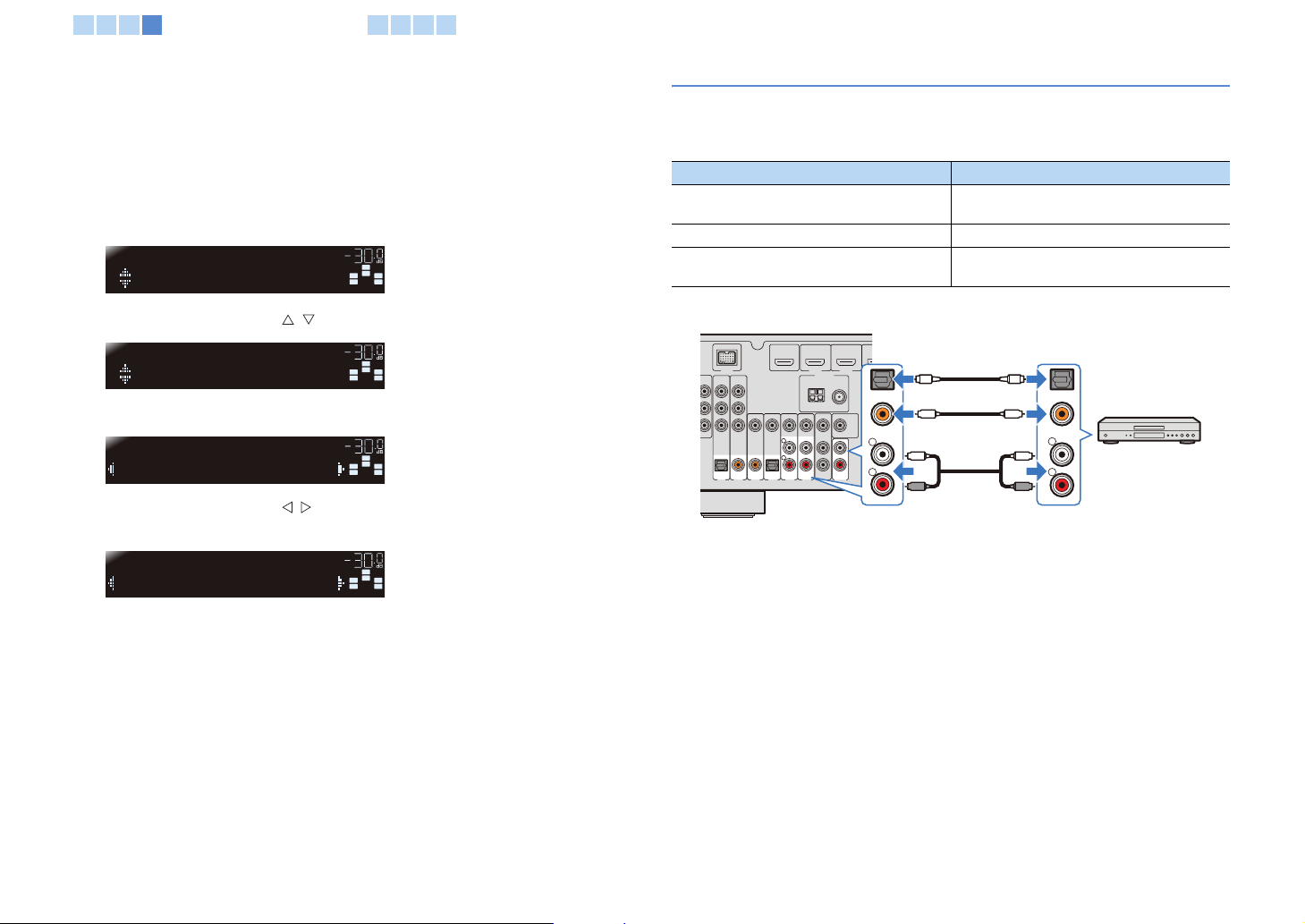
Connecting audio devices (such as a CD player)
Connect audio devices (such as a CD player, MD player and so on) to the unit.
Select a correct connection depending on the output jacks of the audio devices
connected to the unit.
Audio output jack of audio device Audio input jack of the unit
Optical
Coaxial AV2-3 (COAXIAL)
Analog stereo
AV1 (O PTI CAL )
AV4 (O PTI CAL )
AV5-6 (AUDIO)
AUDIO
5 Press the cursor keys ( / ) repeatedly to select “Audio In.”
OPTION
Audio In
92 /
6:
&
5
/
/ 65
6 Press ENTER.
AV2
Audio;;;;;;AV2
VOL
SW
C
R
L
SL SR
7 Press the cursor keys ( / ) repeatedly to select “AV5” as the input
source.
AV2
Audio;;;;;;AV5
Input sources
VOL
SW
C
R
L
SL SR
The unit (rear)
DOCK
MP NENT
VDEO
VID O
R OUT
OAXAL
COA IAL
O T CAL
CD)
AV 3
AV 2
AV 1
HDMI 1
HDMI 2
ANTENNA
FM
AM
7 Ω
MONITOR OUT
OPTCAL
AV
(TV)
UT
AV 5RAV 4
AV 6
AUDO
AV1-6 jacks
AUDIO jack
OO
L
R
OPTICAL
COAX AL
OR
CC
OR
L
R
(any of digital optical,
coaxial, analog stereo)
OPTICAL
COAXIAL
L
L
R
R
Audio output
Audio device
ARC
(BD/DVD)
HDMI OUT
By selecting an input source with the AV1-6 key and AUDIO key, audio from audio
devices is output from the unit.
HDMI1-4, AV1-2
Settings
HDMI1-4, AV1-6, AUDIO
8 Press OPTION.
All settings have been completed.
When switching the input source to “AV2” with the AV2 key, video and audio from
the video device are output from the unit.
En 23

N
1 2 3 4
Connecting playback devices5Connecting the FM/AM antennas
6 7 8
Connecting to the jack on the front panel
Use the VIDEO AUX jacks on the front panel to temporarily connect devices such as a
video camera and a game console. Be sure to stop the device and turn down the
volume before connecting it to the unit.
BD
TV CD ADO
DVD
PORTABLE
VIDEO AUX
VIDEO
L AUDIO R
V RL
NPUT
AUDIO OUT
PROGRAM
STRAGHTTONE CONTROL
Audio output
Portable audio
player
Video camera
VIDEO
AUDIO
V
L
R
Video output
Audio output
By selecting input source as “V-AUX” with the V-AUX key, audio and video from the
connected device are output from the unit.
• To protect against dust, attach the supplied VIDEO AUX input cover when not using this jack.
• When external components are connected to both the PORTABLE jack and the AUDIO jacks, the sound
output from the PORTABLE jack is transmitted.
5 Connecting the FM/AM antennas
Connect supplied indoor FM antenna and an AM antenna.
FM antennaAM antenna
The unit (rear)
A C
BDDVD)
DOCK
OMPONE T
ID O
P
R
P
B
Y
MONITOR OUT
Assembling and connecting the AM antenna
Press and hold
HDMI OUT
HDMI 1
HDMI 2
ANTENNA
AM FM
VDEO
75Ω
MONTOR OUT
HDMI 4
HDM
FRO
R
Insert Release
• From the AM antenna, take some wires, only the number needed for connections.
• The wires of the AM antenna have no polarity.
En 24
SURROUND
SUBWO FER
1 2 3 4 5 6
Connecting recording devices7Connecting the power cable
8
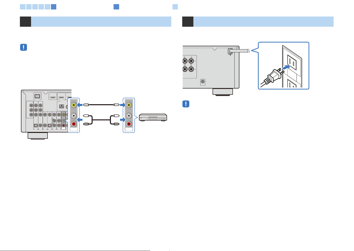
6 Connecting recording devices
Use AV OUT jacks to connect video and audio recording devices. Selected incoming
analog audio/video signals are output through AV OUT jacks.
• When recording video/audio of the video device, use AV5-6 jacks or VIDEO AUX (VIDEO/AUDIO) jacks of
the unit to connect video devices.
• When recording audio of the audio device, use any of AV5-6 jacks, AUDIO jacks or VIDEO AUX (AUDIO)
jacks of the unit to connect audio devices.
The unit (rear)
DOCK
OMPONE T
ID O
P
R
P
B
Y
MONITOR OUT
OPTCAL
AV 1
A C
HDMI OUT
VDEO
C AX AL COAXAL
OP I AL
(CD) TV)
AV 2 AV 3 AV 4 AV 5 AV 6
BDDVD)
HDMI 1
ANTENNA
AM
7
MO
AV
OUT
A
OUT
AV O U T jac ks
V
L
R
AV
Video input
(Analog video)
V
L
R
Audio input
(Analog stereo)
Video/audio
device
7 Connecting the power cable
After all connections are complete, connect the power plug to the outlet.
Plug into a wall outlet
• The figure of the power plug may differ depending upon regions.
En 25
TV
V
OLTV CH
INPUT
MUTE
9010
568
3
MO
SCENE
E
S
CT
O
R
Y
OMUSIC
BD
MUTE
MENU
A
SOURC
R
R
CO
SB
AUDIO
O
ON
S
ETUP
TU
G
S
T
SURDECO
TV
CD
O
TUNER
1
2
3
6
4
1
234
UX
[
]
1 2 3 4 5 6 7 8
CODE SET
DE SET
RECE VER
ECE VE
SOURCE
E
HDMI
1 2 3 4
[ A ]
A
1 2 3
5
5
6
AUDIO
TUNER
FM
AM
PRESET
PRESET
NFO
MEMORY
NFOMEM
SUR DECODE
ENHANCER
NHANCER
SCENE
TV
OPTION
ENTER
DISP A
DISP
TV
TV VOL TV CH
CD
PTI
POP UP
POPUP
MENU
7
10
DE
MOVIE MUSIC
SLEEP D RECT
LEEP D RE
BD
VD
D
SETUP
MODE
DE
9 0
INPUT
MUTE
UX
4
DOCK
DOCK
USB
U
TUNING
NIN
STRAIGHT
TRAIGH
RAD O
RAD
MUTE
4
87
ENT
RECEIVER
Cursor keys
ENTER
Optimizing the speaker settings automatically (YPAO)
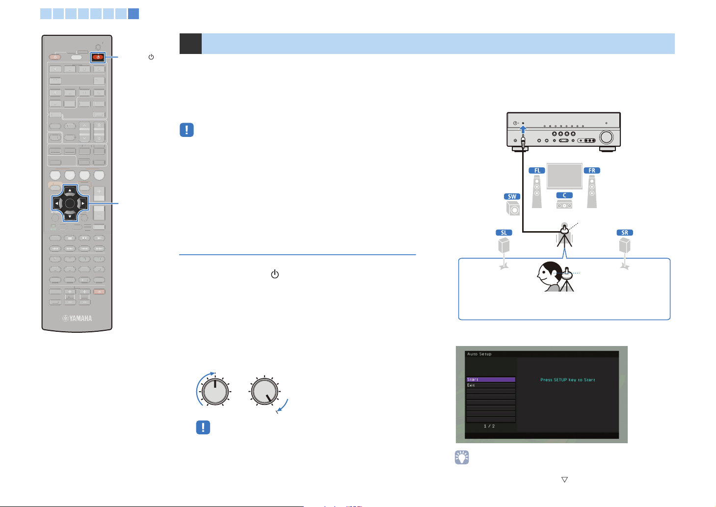
8 Optimizing the speaker settings automatically (YPAO)
The YPAO microphone (supplied) detects the status of speaker
connections and the distance between these speakers and the
listening position, and adjusts the volume balance and the tone
settings automatically (YPAO: Yamaha Parametric room Acoustic
Optimizer).
• Be aware of the following when using YPAO.
- After completing the connection of a TV, speakers, and so on, start YPAO
measurement.
- The test tone is output at a high volume while measuring. Please take care that
the test tone does not frighten any small children. Also, avoid using YPAO at
night, so as to not make your neighbors troubled.
- Keep your room quiet while measuring.
- Do not connect headphones to the unit.
- YPAO can be performed by viewing the front display of the unit.
Preparation before using YPAO
1 Press RECEIVER to turn on the unit.
2 Turn on the TV, and then select the input source of
the TV to the video input from the HDMI OUT jack of
the unit.
3 Turn on the subwoofer, and then set the volume of
the subwoofer to half. The cross-over frequency is
set to maximum if it is present.
VOLUME HIGH CUT
CROSSOVER/
4 Set the YPAO microphone at the height of your ear in
your listening position. Connect the YPAO
microphone to the YPAO MIC jack on the front panel.
The unit (front)
YPAO microphone
listening position
Ear height
Place the YPAO microphone at ear height in your listening position.
We recommend using a tripod to adjust the height. You can use the
tripod screws to fix the microphone in place.
The following display appears on the TV monitor and front
display.
MIN MAXMIN MAX
• When a subwoofer that supports the automatic standby function (turn off
automatically during no signals input) is used, disable the function before
going to the next step.
• To cancel the measurement, disconnect the YPAO microphone before
measuring or press the cursor key ( ) to select “Exit” and press ENTER.
En 26
TV
V
O
INPUT
MU
9
0
5
6
3
MODE
SCENE
S
P
DREC
O
R
Y
O
MUSIC
BD
MUTE
POPU
MENU
L
A
SOURCE
CO
T
SB
O
TU
G
S
S
TV
CD
RADO
TUNER
1
2
3
5
6
4
1
234
UX
DOC
1 2 3 4 5 6 7 8
Optimizing the speaker settings automatically (YPAO)
CODE SET
RECE VER
RECE VER
SOURCE
HDMI
1 2 3 4
[ A ]
[ A ]
1 2 3
5
6
AUDI
AUDIO
TUNER
FM
AM
PRESET
PRESET
NFO
MEMORY
NFOMEM
MOVIE MUSIC
SLEEP D RECT
LEE
BD
VD
D
SETUP
RETURN
MODE
9 0
INPUT
MUTE
TE
TV VOL
TV
ENTER
SCENE
L
SUR DECODE
UR DECODE
ENHANCER
ENHANCER
DISPLA
DISP
TV
CD
POP UP
MENU
STRAIGHT
P
DE SE
DOCK
USB
U
TUNING
TRAIGHT
RAD O
MUTE
UX
4
NIN
4
K
T
SETUP
Cursor keys
ENTER
RETURN
Starting the measurement
Start the measurement by following these steps.
• YPAO measurement is not performed correctly when any obstacles are in the
room.
• While measuring, keep stuff in the corners or remove it from the room. It takes
approximately 3 minutes to finish this measurement.
1 Confirm that “Start” is selected, and then press
SETUP.
The measurement starts in 10 seconds. Press ENTER if you
want to start the measurement immediately.
• To cancel the measurement, press RETURN to stop temporarily, press
ENTER, select “EXIT” and then press ENTER.
• To retry the measurement from the temporary stop, select “RETRY” and then
press ENTER.
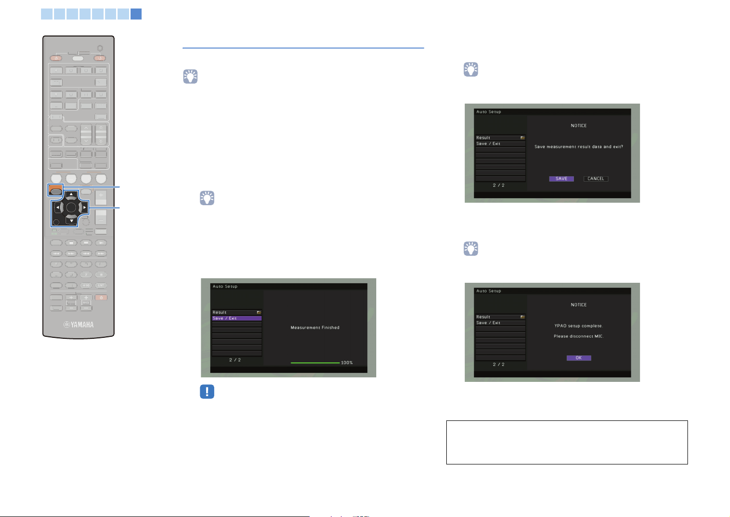
The following screen appears on the TV when the
measurement finishes.
2 Confirm that “Save / Exit” is selected and then press
ENTER.
• To confirm the measurement result, select “Result.” For details, refer to the
“Confirming the measurement result” (p.28).
3 Confirm that “SAVE” is selected, and then press the
ENTER.
• To finish the measurement without saving the result, press the cursor keys to
select “CANCEL” and then press ENTER.
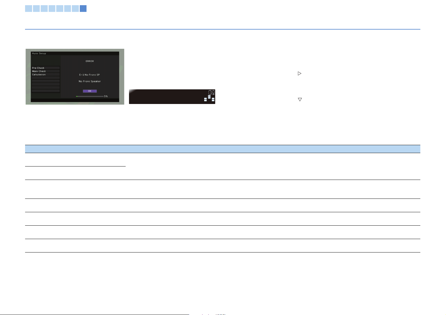
• If an error message (such as “E-1:No Front SP”) or a warning message
(such as “W-1:Out of Phase”) appears, refer to “Error messages” or
“Warning messages” (p.29, 30).
4 Remove the YPAO microphone.
All settings for the speakers have been completed.
CAUTION
• The YPAO microphone is sensitive to heat. Protect YPAO microphone from
high temperatures (such as near AV equipment) and direct sunlight.
En 27
TV
V
OLTV CH
INPUT
MUTE
9010
568
3
MO
SCENE
V
OLU
E
S
P
CT
O
R
Y
OMUSIC
BD
MUTE
TOP
U
MENU
ISP
A
SOURCE
R
R
CO
SB
AUDIO
O
ON
S
ETUP
TU
G
S
T
SUR
TV
CD
O
TUNER
1
2
3
6
4
1
234
UX
[
]
1 2 3 4 5 6 7 8
Optimizing the speaker settings automatically (YPAO)
CODE SET
RECE VER
ECE VE
SOURCE
HDMI
1 2 3 4
[ A ]
A
1 2 3
5
5
6
AUDIO
TUNER
FM
AM
PRESET
PRESET
NFO
MEMORY
NFOMEM
MOVIE MUSIC
SLEEP D RECT
LEE
BD
VD
D
SETUP
RETURN
TOP
MEN
MENU
MODE
DE
9 0
INPUT
MUTE
SUR DECODE
ENHANCER
NHANCER
SCENE
TV
ENTER
TV
TV VOL TV CH
DECODE
CD
OPTION
PTI
ISP A
POP UP
POPUP
7
7
10
STRAIGHT
VOLUME
MENU
DE SET
DOCK
DOCK
USB
U
TUNING
TRAIGH
D RE
RAD O
RAD
MUTE
ENT
UX
4
NIN
4
ME
Cursor keys
ENTER
RETURN
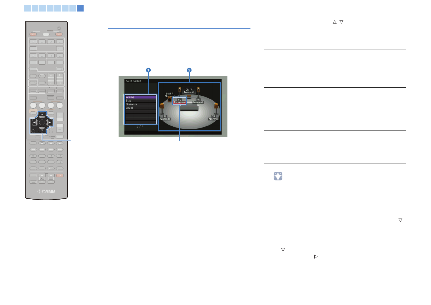
Confirming the measurement result
Confirm the YPAO measurement result.
1 After measurement, press the cursor keys to select
“Result,” and then press ENTER.
The following display appears.
Red-boxed message indicates a speaker that has a problem.
1 Measurement items
2 Measurement result for each speaker
2 Press the cursor keys ( / ) to select an item.
The red-box indicates the speaker that has a problem in the
following items. For details on remedy of each problem, refer to
“Warning messages” (p.30).
Displays the condition of the polarity of each connected
speaker.
Wiring
Size
Distance
Level
• The speaker indicated with red box shows that it may have a certain
“Normal”: Speakers are connected at the normal polarity. (+
and -)
“Reverse”: Speakers are connected at the opposite side of
normal polarity. (+ and -)
Displays the size of the connected speakers.
“Large”: The connected speaker has the ability to
reproduce the low-frequency signals effectively.
“Small”: The connected speaker does not have the ability to
reproduce the low-frequency signals effectively.
The value displayed above “SWFR” describes the cross over
frequency of the subwoofer.
Displays the distance between connected speakers and the
listening position.
Displays the result of the adjustment of output level of
connected speakers.
problem. Check the connection or placement, and if necessary, perform
YPAO again referring “Warning messages” (p.30).
3 To return the previous screen after confirmation,
press ENTER or RETURN.
• (If no problem with the result) Press the cursor key ( )
to select “Save / Exit” and ENTER, and then confirm that
“SAVE” is selected and press ENTER to finish the YPAO.
• (If some problem with the result) Press the cursor key
( ) to select “Save / Exit” and ENTER, and then press
the cursor key ( ) to select “CANCEL” and ENTER. To
restart the YPAO measurement, select “Start.” To finish
the YPAO, select “Exit.”
En 28
1 2 3 4 5 6 7 8
Optimizing the speaker settings automatically (YPAO)
Error messages
If any error message is displayed during the measurement, resolve the problem and perform YPAO again. Error message can be confirmed and controlled by viewing both a TV
monitor and the front display.
■ Procedure to exit YPAO
1 Check the contents of error message, and then press ENTER.
2 Press the cursor key ( ) to select “EXIT (Exit)” from the following
choices, and then press ENTER.
YPAO
E-1:NO FRNT SP
TV monitor Front display
VOL
VOL
SW
SW
C
C
R
L
R
L
SL SR
SL SR
Choices: PROCEED (Proceed) (E-5, E-9 only), “RETRY (Retry),” “EXIT (Exit)”
3 Press the cursor key ( ) to select “Exit (Exit)” from the following
choices, and then press ENTER.
Choices: Start (Start), Exit (Exit)
4 Remove the YPAO microphone.
■ Cause and remedy for each error message
Error message Cause Remedy
E-1:No Front SP
(E-1:NO FRNT SP)
E-2:No Sur. SP
(E-2:NO SUR SP)
E-5:Noisy
(E-5:NOISY)
E-7:No MIC
(E-7:NO MIC)
E-8:No Signal
(E-8:NO SIGNAL)
E-9:User Cancel
(E-9:CANCEL)
E-10:Internal Err.
(E-10:INTERNAL)
Front speakers are not
detected.
Either of surround
speakers is not detected.
The noise is too loud.
The YPAO microphone has
been removed.
The YPAO microphone
cannot detect test tones.
The measurement has
been canceled.
An internal error has
occurred.
Follow “Procedure to exit YPAO” to exit YPAO, turn off the unit, and then check the speaker connections. After removing problems, turn on the unit, and
then perform YPAO again.
Keep the room quiet and select “RETRY (Retry)” in step 2 of “Procedure to exit YPAO” to restart YPAO for an accurate measurement. Selecting
“PROCEED (Proceed)” allows you to continue measuring, but may not achieve the optimal results.
We recommend selecting “RETRY (Retry)” or “EXIT (Exit)” to retry YPAO again from the beginning.
Connect the YPAO microphone to the YPAO MIC jack firmly and select “RETRY (Retry)” in step 2 of “Procedure to exit YPAO” to restart the measurement.
Connect the YPAO microphone to the YPAO MIC jack firmly and select “RETRY (Retry)” in step 2 of “Procedure to exit YPAO” to restart the measurement.
If this error occurs repeatedly, contact the nearest authorized Yamaha dealer or service center.
Select “PROCEED (Proceed)” in step 2 of “Procedure to exit YPAO” to resume the measurement. Select “RETRY (Retry)” to restart the measurement from
first.
Follow “Procedure to exit YPAO” to exit YPAO, turn off and on the unit. Perform YPAO again. If this error occurs repeatedly, contact the nearest authorized
Yamaha dealer or service center.
En 29
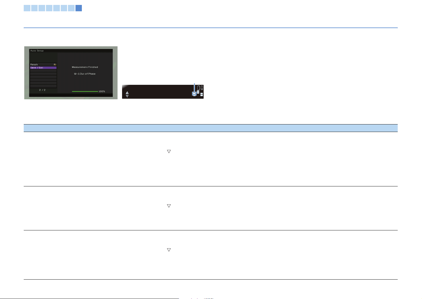
1 2 3 4 5 6 7 8
Optimizing the speaker settings automatically (YPAO)
Warning messages
Even if any warning message is displayed after the measurement, you can save the measurement results. However, we recommend that you perform YPAO again for the optimal
speaker settings.
The speaker indicator that has a
YPAO
W-1:PHASE
problem flashes.
VOL
VOL
SW
SW
C
C
L
L
R
R
SR
SR
TV monitor Front display
■ Cause and remedy for each warning message
Warning message Cause Remedy
a Check the speaker with warning (indicated with red box) in “Wiring” (p.28).
b Check the connection of the speaker with warning.
c Press RETURN to return to the previous screen.
W-1:Out of Phase
(W-1:PHASE)
W-2:Over Distance
(W-2:DISTANCE)
W-3:Lev el Error
(W-3:LEVEL)
Any of the speaker cables
may be connected with the
reversed polarity (+/-).
Any of the speakers is
placed too far from the
listening position.
There are a significant
volume differences
between the speakers.
d Press the cursor key ( ) to select “Save / Exit” and press ENTER.
e (If some trouble): Select “EXIT (Exit)” and press ENTER.
(If no trouble): Select “SAVE (Save)” and press ENTER.
f Remove the YPAO microphone to finish YPAO.
g (If some trouble) Turn off the unit and reconnect the speaker. After reconnecting, perform YPAO again.
When using the speakers that are designed with reverse polarity for better performance, this warning may appear even if the speakers are connected
properly.
a Check the speaker with warning (indicated with red box) in “Distance” (p.28).
b Check the placement of the speaker with warning.
c Press RETURN to return to the previous screen.
d Press the cursor key ( ) to select “Save / Exit” and press ENTER.
e (If some trouble): Select “EXIT (Exit)” and press ENTER.
(If no trouble): Select “SAVE (Save)” and press ENTER.
f Remove the YPAO microphone to finish YPAO.
g (If some trouble) Turn off the unit and relocate the speaker. After relocating, perform YPAO again.
a Check the speaker with warning (indicated with red box) in “Level” (p.28).
b Check the connection of the speaker with warning. Also check the use environment, or the volume of the subwoofer.
c Press RETURN to return to the previous screen.
d Press the cursor key ( ) to select “Save / Exit” and press ENTER.
e (If some trouble): Select “EXIT (Exit)” and press ENTER.
(If no trouble): Select “SAVE (Save)” and press ENTER.
f Remove the YPAO microphone to finish YPAO.
g (If some trouble) Turn off the unit and resolve the problem. After resolving the problem, perform YPAO again.
We recommend using the same speakers or speakers with as similar as possible.
En 30
 Loading...