

Page 1

RX-N600D
AV Receive r
B
OWNER’S MANUAL
Page 2

CAUTION: READ THIS BEFORE OPERATING YOUR UNIT.
CAUTION: READ THIS BEFORE OPERATING YOUR UNIT.
1 To assure the finest performance, please read this manual
carefully. Keep it in a safe place for future reference.
2 Install this sound system in a well ventilated, cool, dry, clean
place – away from direct sunlight, heat sources, vibration,
dust, moisture, and/or cold. Allow ventilation space of at
least 30 cm on the top, 20 cm on the left and right, and 20
cm on the back of this unit.
3 Locate this unit away from other electrical appliances,
motors, or transformers to avoid humming sounds.
4 Do not expose this unit to sudden temperature changes from
cold to hot, and do not locate this unit in an environment
with high humidity (i.e. a room with a humidifier) to prevent
condensation inside this unit, which may cause an electrical
shock, fire, damage to this unit, and/or personal injury.
5 Avoid installing this unit where a foreign object may fall
onto this unit and/or this unit may be exposed to liquid
dripping or splashing. On the top of this unit, do not place:
– other components, as they may cause damage and/or
discoloration on the surface of this unit.
– burning objects (i.e. candles), as they may cause fire,
damage to this unit, and/or personal injury.
– containers with liquid in them, as they may fall and
liquid may cause electrical shock to the user and/or
damage to this unit.
6 Do not cover this unit with a newspaper, tablecloth, curtain,
etc. in order not to obstruct heat radiation. If the temperature
inside this unit rises, it may cause fire, damage to this unit,
and/or personal injury.
7 Do not plug in this unit to a wall outlet until all connections
are complete.
8 Do not operate this unit upside-down. It may overheat,
possibly causing damage.
9 Do not use force on switches, knobs and/or cords.
10 When disconnecting the power cable from the wall outlet,
grasp the plug; do not pull the cord.
11 Do not clean this unit with chemical solvents; this might
damage the finish. Use a clean, dry cloth.
12 Only voltage specified on this unit must be used. Using this
unit with a higher voltage than specified is dangerous and
may cause fire, damage to this unit, and/or personal injury.
YAMAHA will not be held responsible for any damage
resulting from use of this unit with a voltage other than
specified.
13 To prevent damage by lightning, keep the power cable and
outdoor antennas disconnected from a wall outlet or this unit
during a lightning storm.
14 Do not attempt to modify or fix this unit. Contact qualified
YAMAHA service personnel when any service is needed.
The cabinet should never be opened for any reasons.
15 When not planning to use this unit for long periods of time
(i.e. vacation), disconnect the AC power plug from the wall
outlet.
16 Install this unit near the AC wall outlet where the power
cable plug can be reached easily.
17 Be sure to read the “TROUBLESHOOTING” section on
common operating errors before concluding that this unit is
faulty.
18 Before moving this unit, press MASTER ON/OFF to release
it outward to the OFF position to turn off this unit, and then
disconnect the power cable from the AC wall outlet.
WAR NING
TO REDUCE THE RISK OF FIRE OR ELECTRIC
SHOCK, DO NOT EXPOSE THIS UNIT TO RAIN
OR MOISTURE.
This unit is not disconnected from the AC power
source as long as it is connected to the wall outlet, even
if this unit itself is turned off. In this state, this unit is
designed to consume a very small quantity of power.
■ For U.K. customers
If the socket outlets in the home are not suitable for the
plug supplied with this appliance, it should be cut off and
an appropriate 3 pin plug fitted. For details, refer to the
instructions described below.
Note
The plug severed from the mains lead must be destroyed, as a
plug with bared flexible cord is hazardous if engaged in a live
socket outlet.
■ Special Instructions for U.K. Model
IMPORTANT
THE WIRES IN MAINS LEAD ARE COLOURED IN
ACCORDANCE WITH THE FOLLOWING CODE:
Blue: NEUTRAL
Brown: LIVE
As the colours of the wires in the mains lead of this
apparatus may not correspond with the coloured
markings identifying the terminals in your plug,
proceed as follows:
The wire which is coloured BLUE must be connected
to the terminal which is marked with the letter N or
coloured BLACK. The wire which is coloured
BROWN must be connected to the terminal which is
marked with the letter L or coloured RED.
Making sure that neither core is connected to the earth
terminal of the three pin plug.
Page 3

CONTENTS
INTRODUCTION
FEATURES ............................................................. 2
GETTING STARTED............................................ 3
Supplied accessories .................................................. 3
Installing batteries in the remote control ................... 3
CONTROLS AND FUNCTIONS ......................... 4
Front panel ................................................................. 4
Remote control........................................................... 6
Front panel display .................................................... 9
Rear panel ................................................................ 11
PREPARATION
CONNECTIONS .................................................. 12
Placing speakers....................................................... 12
Connecting speakers ................................................ 13
Information on jacks and cable plugs ...................... 15
Audio and video signal flow .................................... 16
Connecting a TV...................................................... 17
Connecting a DVD player, a DVD recorder,
a VCR or an STB................................................. 18
Connecting a CD player, an MD player or a tape deck
Connecting a YAMAHA iPod universal dock ........21
Connecting the network ........................................... 22
Connecting a multi-format player,
an external decoder or a sound processor ............ 23
Connecting a game console, a video camera
or a portable audio player .................................... 23
Connecting the FM and AM antennas ..................... 24
Connecting the DAB antenna .................................. 25
Connecting the power cable..................................... 26
Setting the speaker impedance................................. 27
Turning on and off the power .................................. 28
........ 20
BASIC SETUP ...................................................... 29
BASIC OPERATION
PLAYBACK.......................................................... 32
USING AUDIO FEATURES ............................... 34
Using SILENT CINEMA ........................................ 34
Muting the audio output........................................... 34
Selecting the night listening mode........................... 34
Selecting the input mode ......................................... 35
Using the sleep timer ............................................... 35
Adjusting the speaker level...................................... 36
Selecting the Compressed Music Enhancer mode... 37
Selecting the MULTI CH INPUT component ......... 38
Enjoying multi-channel sources in 2-channel stereo39
Enjoying unprocessed input sources........................ 39
Enjoying pure hi-fi stereo sound.............................. 39
USING VIDEO FEATURES ............................... 40
Displaying the input source information ................. 40
Selecting the OSD mode.......................................... 41
Playing video sources in the background ................ 41
ENJOYING SURROUND SOUND .................... 42
Enjoying multi-channel sources
in 6.1-channel surround ....................................... 42
Enjoying 2-channel sources in surround.................. 43
Using Virtual CINEMA DSP .................................. 44
RECORDING ....................................................... 45
FM/AM TUNING ..................................................46
Automatic tuning ..................................................... 46
Manual tuning .......................................................... 47
Automatic preset tuning........................................... 48
Manual preset tuning ............................................... 49
Selecting preset stations........................................... 50
Exchanging preset stations ...................................... 51
RADIO DATA SYSTEM TUNING ..................... 53
Selecting the Radio Data System program .............. 53
Using the Radio Data System station network ........ 54
Displaying the Radio Data System information ...... 55
DAB (DIGITAL AUDIO BROADCASTING) TUNING
Preparing the DAB tuning ....................................... 58
DAB tuning.............................................................. 59
DAB preset tuning ................................................... 60
Selecting preset DAB services................................. 62
DAB service information......................................... 63
Using DAB MENU ................................................. 64
SOUND FIELD PROGRAMS
SOUND FIELD PROGRAMS .............................70
Selecting sound field programs ............................... 70
Sound field program descriptions ............................ 71
Changing sound field parameter settings................. 73
ADVANCED OPERATION
SET MENU ............................................................ 79
Using SET MENU ................................................... 81
1 SOUND MENU.................................................... 82
2 INPUT MENU...................................................... 87
3 DAB MENU ......................................................... 89
4 NET/USB MENU................................................. 90
5 OPTION MENU................................................... 92
ADVANCED SETUP ............................................94
REMOTE CONTROL FEATURES ...................96
Controlling this unit, a TV, or other components .... 96
Setting the remote control code ............................... 98
Setting library codes ................................................ 99
Resetting all remote control codes......................... 100
USING MULTI-ZONE CONFIGURATION ... 101
Connecting Zone 2................................................. 101
Controlling Zone 2................................................. 102
USING iPod®....................................................... 104
Controlling iPod .................................................... 104
USING NETWORK/USB FEATURES.............106
Navigating the network and USB menus .............. 106
Using a PC server or YAMAHA MCX-2000........ 108
Using the Internet radio ......................................... 109
Using a USB memory device or a USB portable audio player
RESETTING THE SYSTEM.............................111
ADDITIONAL INFORMATION
TROUBLESHOOTING .....................................112
GLOSSARY.........................................................119
Audio information ................................................. 119
Video information.................................................. 121
Sound field program information .......................... 121
DAB frequency information .................................. 122
SPECIFICATIONS.............................................123
.....57
.... 110
PREPARATIONINTRODUCTION
OPERATION
BASIC
SOUND FIELD
PROGRAMS
OPERATION
ADVANCED
INFORMATION
ADDITIONAL
1 En
Page 4

FEATURES
®
“iPod” i
“S
FEATURES
Built-in 6-channel power amplifier
◆ Minimum RMS output power
(20 Hz to 20 kHz, 0.06% THD, 8 Ω)
Front: 95 W + 95 W
Center: 95 W
Surround: 95 W + 95 W
Surround back: 95 W
Sound field programs
◆ Proprietary YAMAHA technology for the creation of sound
fields
◆ Dolby Digital/Dolby Digital EX decoder
◆ DTS/DTS-ES Matrix 6.1, Discrete 6.1, DTS Neo:6,
DTS 96/24 decoder
◆ Dolby Pro Logic/Dolby Pro Logic II/
Dolby Pro Logic IIx decoder
◆ Virtual CINEMA DSP
◆ SILENT CINEMA
™
Sophisticated AM/FM tuner
◆ 40-station random and direct preset tuning
◆ Automatic preset tuning
◆ Preset station shifting capability (preset editing)
Radio Data System
◆ Radio Data System tuning capability
DAB (Digital Audio Broadcasting)
◆ DAB (Digital Audio Broadcasting) tuning capability
◆ DLS (Dynamic Label Segment) information display
◆
Initial scan function to locate all DAB services in your area
◆ Tuning aid function to optimize DAB reception
iPod controlling capability
◆ DOCK terminal to connect a YAMAHA iPod universal dock
(such as YDS-10 sold separately), which supports iPod (Click
and Wheel), iPod nano, and iPod mini
Network features
◆ LAN port to connect a PC and YAMAHA MCX-2000 or
access the Internet radio via a LAN
◆ DHCP automatic or manual network configuration
USB features
◆ USB port to connect a USB memory device or a USB portable
audio player
Other features
◆ 192-kHz/24-bit D/A converter
◆ OSD (on-screen display) menus that allow you to optimize
this unit to suit your individual audiovisual system
◆ 6 additional input jacks for discrete multi-channel input
◆ S-video signal input/output capability
◆ Component video input/output capability
(3 COMPONENT VIDEO INs and 1 MONITOR OUT)
◆ Digital video signal conversion (composite video ↔
S-video → component video) capability for monitor out
◆ Optical and coaxial digital audio signal jacks
◆ Sleep timer
◆ Cinema and music night listening modes
◆ Remote control with preset remote control codes,
backlighting input selector buttons, and an iPod (stationed in a
YAMAHA iPod universal dock connected to the DOCK
terminal) controlling capability
◆ Zone 2 custom installation facility
◆ Zone switching capability between the main zone and Zone 2
using ZONE CONTROL
◆ Compressed Music Enhancer mode to improve the sound
quality of compression artifacts (such as the MP3 format) to
that of a high-quality stereo
Manufactured under license from Dolby
Laboratories.
“Dolby”, “Pro Logic”, and the double-D
symbol are trademarks of Dolby
Laboratories.
Manufactured under license from Digital
Theater Systems, Inc. “DTS”, “DTS-ES”,
“NEO:6”, and “DTS 96/24” are trademarks
of Digital Theater Systems, Inc. Copyright
1996, 2003 Digital Theater Systems, Inc. All
right reserved.
The “DAB Digital Radio” logo and the stylised “r” mark ® and ©
Digital One Limited.
This receiver supports DAB tuning.
iPod
2 En
s a trademark of Apple Computer,
Inc., registered in the U.S. and other
countries.
MPEG Layer-3 audio coding technology licensed from
Fraunhofer IIS and Thomson.
This receiver supports network connections.
ILENT CINEMA” is a trademark of
YAMAHA CORPORATION.
This unit contains programs licensed under the GNU General
Public License and GNU Lesser General Public License.
Windows XP, Windows Media Audio, Windows Media Connect
are either registered trademarks or trademarks of Microsoft
corporation in the United States and/or countries.
Page 5
GETTING STARTED
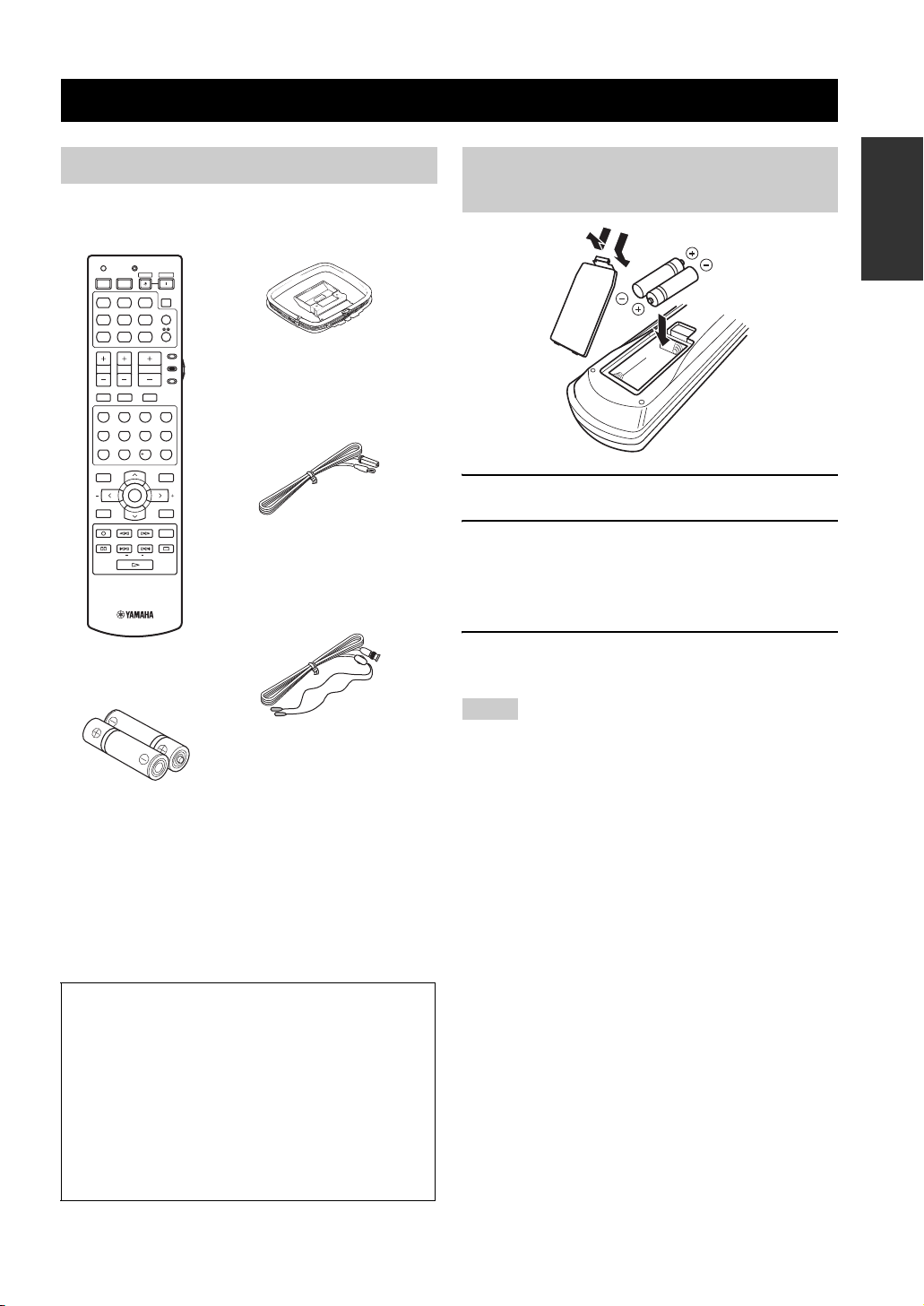
Supplied accessories
Check that you received all of the following parts.
GETTING STARTED
INTRODUCTION
Installing batteries in the remote control
Remote control
TRANSMITCODE SET
STANDBY
POWER
POWERPOWER
AVTV
SLEEP
MD
CD-R
CD
DVD DTV
DOCK USB
V-AUX DVR
TV VOL TV CH
TV MUTE TV INPUT
STEREO
1
STANDARD
5
SPEAKERS
9
LEVEL
BAND
REC
PC/MCX
FREQ/TEXT EONSTARTPTY SEEKMODE
CBL
MUSIC
SELECT
ENHANCER
NET RADIO
MULTI CH IN
TUNER
NET
AMP
SOURCE
VOLUME
TV
MUTE
ENTERTAIN
MOVIE
2
3
4
EXTD SUR.
DIRECT ST.
6
7
8
NIGHT
STRAIGHT
0
10
ENT.
EFFECT
PRESET/CH
SET MENU
MENUTITLE
SRCH MODE
ENTER
A/B/C/D/E
DISPLAYRETURN
ON SCREENDAB MEMORY
AUDIO
USB
AM loop antenna
Indoor FM antenna
Indoor DAB antenna
Batteries (2)
(AA, R6, UM-3)
About this manual
• y indicates a tip for your operation.
• Some operations can be performed by using either the
buttons on the front panel or the ones on the remote control.
In case the button names differ between the front panel and
the remote control, the button name on the remote control is
given in parentheses.
• This manual is printed prior to production. Design and
specifications are subject to change in part as a result of
improvements, etc. In case of differences between the
manual and product, the product has priority.
1
3
2
1 Take off the battery compartment cover.
2 Insert the two supplied batteries
(AA, R6, UM-3) according to the polarity
markings (+ and –) on the inside of the
battery compartment.
3 Snap the battery compartment cover back
into place.
Notes
• Change all of the batteries if you notice the following
conditions:
– the operation range of the remote control decreases.
– the TRANSMIT indicator does not flash or its light becomes
dim.
• Do not use an old battery together with a new one.
• Do not use different types of batteries (such as alkaline and
manganese batteries) together. Read the packaging carefully as
these different types of batteries may have the same shape and
color.
• If the batteries have leaked, dispose of them immediately. Avoid
touching the leaked material or letting it come into contact with
clothing, etc. Clean the battery compartment thoroughly before
installing new batteries.
• Do not throw away batteries with general house waste; dispose
of them correctly in accordance with your local regulations.
• If the remote control is without batteries for more than 2
minutes, or if exhausted batteries remain in the remote control,
the contents of the memory may be cleared. When the memory
is cleared, insert new batteries and set up the remote control
code that may have been cleared.
3 En
Page 6
CONTROLS AND FUNCTIONS
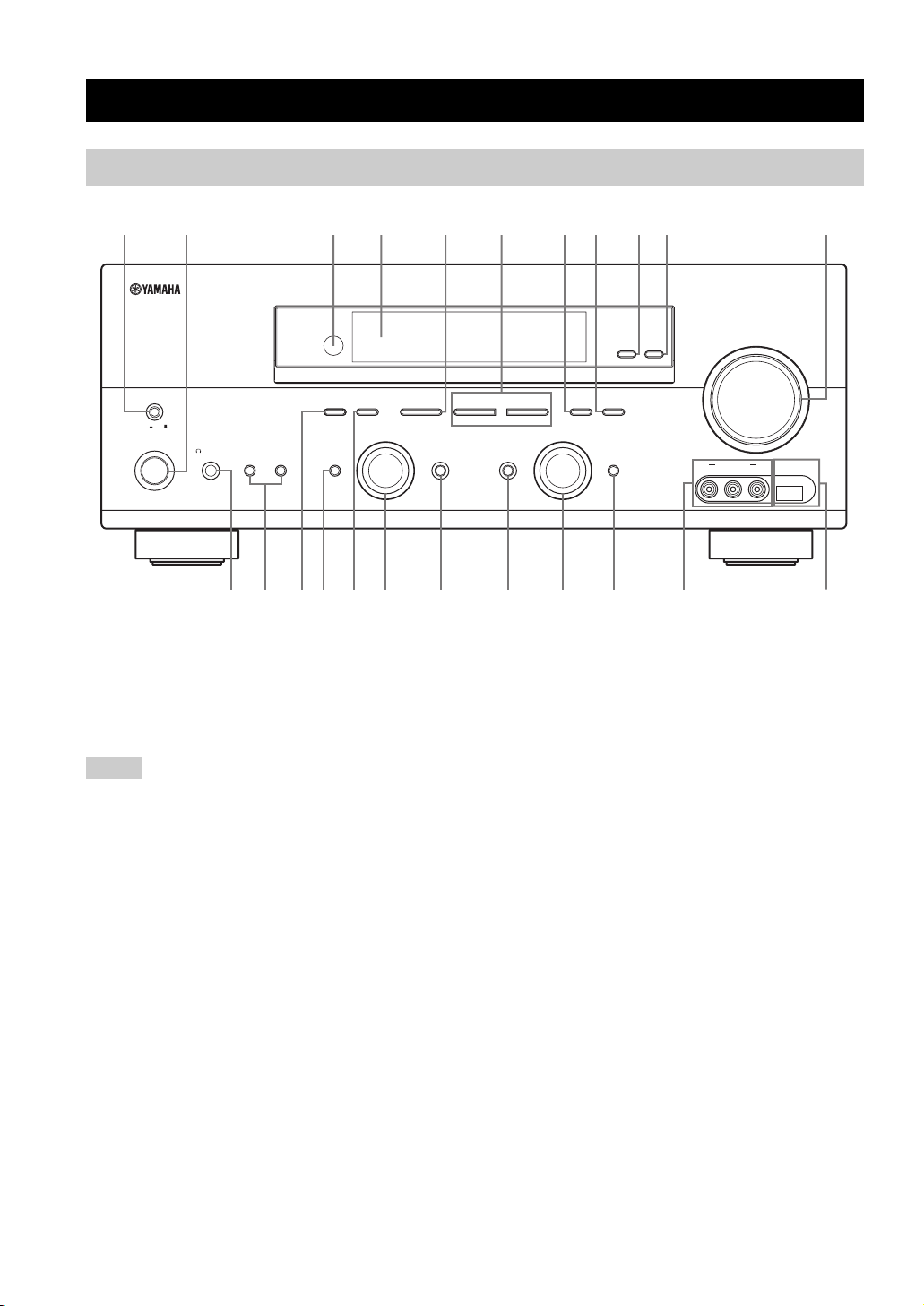
Front panel
CONTROLS AND FUNCTIONS
3145687
MASTER
ON OFF
MAIN ZONE
ON/OFF
SILENT CINEMA
SPEAKERSPHONES
BA
PRESET/TUNING
EDIT
EFFECT
FM/AM
A/B/C/D/E
NEXT
DABSEARCH MODE
PROGRAM
BC2EH
1 MASTER ON/OFF
Turns on or off this unit (see page 28).
2 MAIN ZONE ON/OFF
Turns on the main zone or sets it to the standby mode
(see page 28).
Notes
• In the standby mode, this unit consumes a small amount of
power in order to receive infrared signals from the remote
control.
• When you turn on this unit, there will be a 4 to 5-second delay
before this unit can reproduce sound.
• This button is operational only when MASTER ON/OFF is
pressed inward to the ON position.
3 Remote control sensor
Receives signals from the remote control (see page 8).
4 Front panel display
Shows information about the operational status of this unit
(see page 9).
5 A/B/C/D/E, NEXT
• Selects one of the 5 preset station groups (A to E) when
this unit is in the FM/AM tuning mode (see page 46).
• Selects the DAB service on top of the list when this
unit is in the DAB tuning mode (see page 57).
• Selects the speaker channel whose output level you
want to adjust (see page 37).
90
VIDEO L AUDIO R
VOLUME
USBVIDEO AUX
ZONE 2
ZONE
ON/OFF
CONTROL
TUNING MODE
l PRESET/TUNING h
LEVEL
INPUT MODETONE CONTROLSTRAIGHT
IJKGFD
MEMORY
MAN'L/AUTO FM
AUTO/MAN'L
DISPLAY
INPUT
MULTI CH
INPUT
L
6 PRESET/TUNING l / h, LEVEL
• Selects one of the 8 preset station numbers (1 to 8)
when this unit is in the FM/AM tuning mode. The
colon (:) is displayed in the front panel display
(see page 48).
• Selects the tuning frequency when this unit is in the
FM/AM tuning mode. The colon (:) is not displayed in
the front panel display (see page 46).
• Browses through the list of stored or preset DAB
services when this unit is in the DAB tuning mode
(see page 59).
• Adjusts the level of the speaker channel selected using
NEXT when “TUNER” is not selected as the input
source (see page 37).
7 MEMORY (MAN’L/AUTO FM)
• Stores a preset station in the memory when this unit is
in the FM/AM tuning mode. Hold down this button for
more than 3 seconds to start automatic preset tuning
(see page 48).
• Stores a preset DAB service in the memory when this
unit is in the DAB tuning mode (see page 60).
A
M
4 En
Page 7

CONTROLS AND FUNCTIONS
8 TUNING MODE (AUTO/MAN’L), DISPLAY
• Switches between automatic tuning (the AUTO
indicator is turned on) and manual tuning (the AUTO
indicator is turned off) when this unit is in the FM/AM
tuning mode (see page 46).
• Displays various information about the DAB service
currently being broadcast when this unit is in the DAB
tuning mode (see page 63).
9 ZONE 2 ON/OFF
Turns on Zone 2 or sets it to the standby mode
(see page 102).
Note
This button is operational only when MASTER ON/OFF is
pressed inward to the ON position.
0 ZONE CONTROL
Switches the zone you want to control between the main
zone and Zone 2 (see page 102).
y
When Zone 2 is selected, the ZONE2 indicator flashes in the front
panel display for approximately 5 seconds. While the indicator is
flashing, perform the desired operation.
A VOLUME
Controls the output level of all audio channels.
y
This does not affect the AUDIO OUT (REC) level.
B PHONES (SILENT CINEMA) jack
Outputs audio signals for private listening with
headphones (see page 34).
Notes
• When you connect headphones, no signals are output at the
SUBWOOFER OUTPUT jack or the speaker terminals.
• All Dolby Digital and DTS audio signals are mixed down to the
left and right headphone channels.
C SPEAKERS A/B
Turns on or off the set of front speakers connected to the
FRONT A and/or B terminals on the rear panel each time
the corresponding button is pressed.
D PRESET/TUNING, EDIT, SEARCH MODE
• Switches the function of PRESET/TUNING l / h
between selecting preset station numbers and selecting
the tuning frequency when this unit is in the FM/AM
tuning mode.
• Edits the assignments of preset stations when this unit
is in the FM/AM tuning mode (see page 51).
• Switches between the five DAB tuning methods when
this unit is in the DAB tuning mode (see page 59).
E STRAIGHT (EFFECT)
Turns the sound field programs off or on. When the
“STRAIGHT” mode is selected, 2-channel or multichannel input signals are output directly from their
respective speakers without effect processing (see
page 39).
F FM/AM, DAB
Switches the reception band between FM, AM and DAB
when “TUNER” is selected as the input source
(see pages 46 and 58).
G PROGRAM selector
Selects sound field programs or adjusts the bass/treble
balance in conjunction with TONE CONTROL
(see page 33).
H TONE CONTROL
Adjusts the bass/treble balance of the front left and right
speakers in conjunction with the PROGRAM selector
(see page 33).
I INPUT MODE
Selects either digital or analog input signals exclusively or
sets this unit to automatically detect the type of input
signals and select the corresponding input signals when
one component is connected via both digital and analog
connections (see page 35).
J INPUT selector
Selects the desired input source.
K MULTI CH INPUT
Selects the component connected to the MULTI CH
INPUT jacks as the input source (see page 38).
Note
The input source connected to the MULTI CH INPUT jacks takes
priority over the source selected with the INPUT selector on the
front panel (or the input selector buttons on the remote control).
L VIDEO AUX jacks
Input audio and video signals from a portable external
source such as a game console, a video camera or a
portable audio player (see page 23).
y
To reproduce the source signals input at these jacks, select
“V-AUX” as the input source.
Note
The audio signals input at the DOCK terminal on the rear panel
take priority over the ones input at the VIDEO AUX jacks.
M USB port
Use to connect a USB memory device or a USB portable
audio player (see page 110).
INTRODUCTION
5 En
Page 8
CONTROLS AND FUNCTIONS
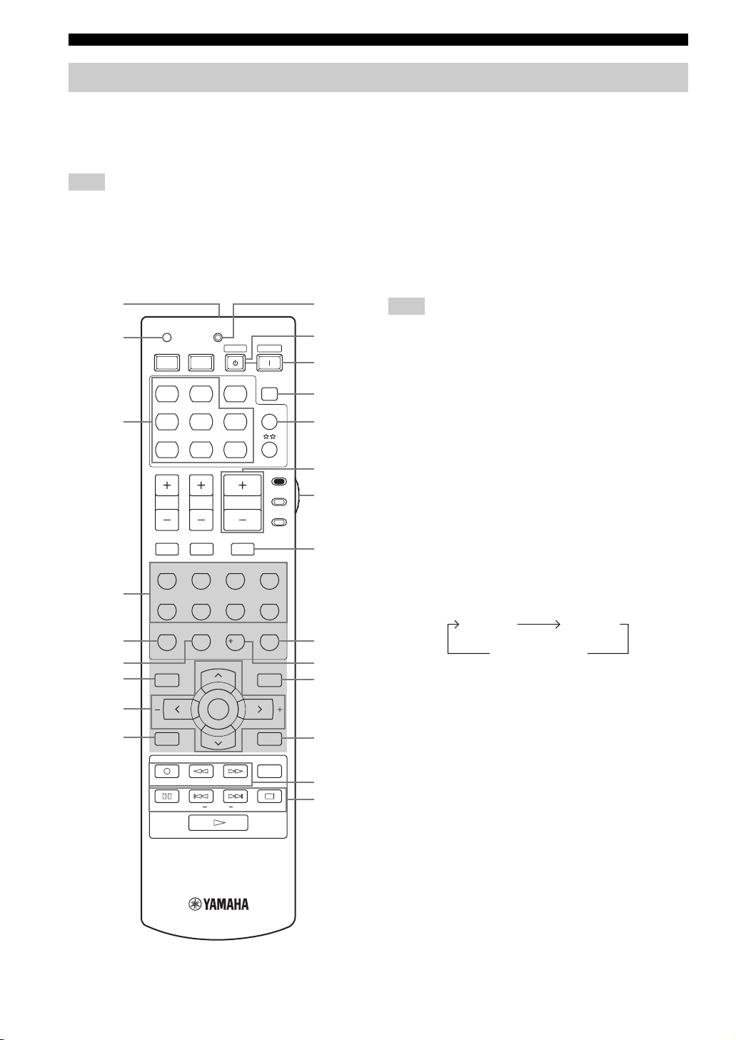
Remote control
This section describes the function of each control on the
remote control used to control this unit. To operate other
components, see “REMOTE CONTROL FEATURES” on
page 96.
Note
The operation mode of the remote control buttons in the shaded
area below depends on the component selector switch position.
Set the component selector switch to AMP to control this unit. To
control the TUNER functions, set the component selector switch
to SOURCE and then press TUNER to select “TUNER” as the
input source.
1
2
3
TRANSMITCODE SET
STANDBY
POWERPOWER
AVTV
MD
CD-R
CD
CBL
DVD DTV
DOCK USB
V-AU X DVR
TV VOL TV CH
TUNER
NET
VOLUME
POWER
SLEEP
MULTI CH IN
SOURCE
AMP
0
A
B
C
D
E
F
TV
■ Controlling this unit
Set the component selector switch to AMP to control this
unit.
1 Infrared window
Outputs infrared control signals. Aim this window at the
component you want to operate (see page 8).
2 CODE SET
Use to set up remote control codes (see page 98).
3 Input selector buttons
Select the input source you want to control.
Note
The corresponding input selector button for the currently selected
input source lights up for approximately 5 seconds after you press
any buttons on the remote control, showing which source
component is currently being operated.
4 Sound field program selector buttons
Select sound field programs (see page 70).
– Use SELECT to play back 2-channel sources in
surround (see page 43).
– Use EXTD SUR. to switch between 5.1 and
6.1-channel playback of multi-channel sources
(see page 42).
– Use DIRECT ST. to play back 2-channel sources in
hi-fi stereo sound (see page 39).
4
5
6
7
8
9
TV MUTE TV INPUT
STEREO
1
STANDARD
5
SPEAKERS
ENHANCER
9
LEVEL
BAND
REC
NET RADIO
PC/MCX
FREQ/TEXT EONSTARTPTY SEEKMODE
MUSIC
2
SELECT
6
0
ENTERTAIN
EXTD SUR.
PRESET/CH
ENTER
NIGHT
USB
MUTE
3
7
10
MOVIE
DIRECT ST.
STRAIGHT
EFFECT
SET MENU
MENUTITLE
SRCH MODE
A/B/C/D/E
DISPLAYRETURN
ON SCREENDAB MEMORY
AUDIO
G
5 SPEAKERS
Turns on or off the set of front speakers connected to the
4
FRONT A and/or B terminals on the rear panel. Press this
button repeatedly to toggle as follows:
8
ENT.
H
I
J
6 ENHANCER
A on B on
A and B off
Turns on or off the Compressed Music Enhancer mode
(see page 37).
K
7 LEVEL
Selects the speaker channel to be adjusted and sets the
output level (see page 36).
L
M
8 Cursor buttons u / d / j / i, ENTER
Select and adjust the sound field program parameters or
the “SET MENU” parameters.
9 RETURN
Returns to the previous menu level when adjusting the
“SET MENU” parameters.
6 En
Page 9

CONTROLS AND FUNCTIONS
0 TRANSMIT indicator
Flashes while the remote control is sending infrared
signals.
A STANDBY
Sets this unit to the standby mode (see page 28).
Note
This button is operational only when MASTER ON/OFF on the
front panel is pressed inward to the ON position.
B POWER
Turns on this unit (see page 28).
Note
This button is operational only when MASTER ON/OFF on the
front panel is pressed inward to the ON position.
C SLEEP
Sets the sleep timer (see page 35).
D MULTI CH IN
Selects the component connected to the MULTI CH
INPUT jacks as the input source when using an external
decoder, etc. (see page 38).
E VOLUME +/–
Increases or decreases the volume level.
F Component selector switch
Selects the operation mode of the remote control buttons
in the shaded area.
AMP
Operates this unit.
SOURCE
Operates the component selected with an input
selector button (see page 97).
TV
Operates the TV assigned to either DTV/CBL or
(see page 96).
Notes
• To set the remote control codes for other components, see
page 98.
• When you set the remote control codes for both DTV/CBL and
(see page 98), priority is given to the one set for DTV/
CBL.
G MUTE
Mutes the audio output. Press again to restore the audio
output to the previous volume level (see page 34).
H STRAIGHT (EFFECT)
Turns the sound field programs off or on. When the
“STRAIGHT” mode is selected, 2-channel or multichannel input signals are output directly from their
respective speakers without effect processing (see
page 39).
I NIGHT
Turns on or off the night listening modes (see page 34).
J SET MENU
Enters “SET MENU” (see page 81).
K DISPLAY
Selects the on-screen display (OSD) mode for your video
monitor (see page 41).
L Network and USB input selector buttons
Select the sub input source of NET/USB (see page 106).
PC/MCX
Selects a PC server or YAMAHA MCX-2000 as the
sub input source of NET/USB.
NET RADIO
Selects the Internet radio as the sub input source of
NET/USB.
USB
Selects a USB memory device or a USB portable
audio player as the sub input source of NET/USB.
Notes
• Press NET/USB to select “NET/USB” as the input source
before you press any of the network and USB input selector
buttons stated above to select the corresponding sub input
source of NET/USB.
• When you press any of the network and USB input selector
buttons, the contents previously played for the corresponding
sub input source of NET/USB is automatically played.
M Radio Data System tuning buttons
FREQ/TEXT
Switches the Radio Data System display between the
PS mode, PTY mode, RT mode, CT mode (if the
station offers the corresponding data services) and the
frequency display (see page 56).
PTY SEEK MODE
Sets this unit to the PTY SEEK mode (see page 53).
PTY SEEK START
Starts searching for a station once the desired program
type is selected in the PTY SEEK mode (see page 54).
EON
Selects a program type (NEWS, AFFAIRS, INFO, or
SPORT) for automatic tuning (see page 55).
INTRODUCTION
7 En
Page 10
CONTROLS AND FUNCTIONS
■ Controlling the TUNER
(FM/AM and DAB) functions
Set the component selector switch to SOURCE and then
press TUNER to select “TUNER” as the input source.
Press BAND repeatedly to switch the reception band
between FM, AM and DAB.
456Numeric buttons
• Use numbers 1 through 8 to select preset stations when
this unit is in the FM/AM tuning mode (see page 50).
• Select preset DAB services when this unit is in the
DAB tuning mode (see page 62).
7 BAND
Switches the reception band between FM, AM and DAB
(See pages 46 and 58).
8 Cursor buttons u / d / j / i
• Press A/B/C/D/E j / i to select a preset station group
(A to E) and PRESET/CH u / d to select a preset
station number (1 to 8) when this unit is in the FM/AM
tuning mode (see page 50).
• Press PRESET/CH u / d to select a preset service
number when this unit is in the DAB tuning mode
(see page 62).
9 DAB MEMORY
Stores a preset DAB service in the memory when this unit
is in the DAB tuning mode (see page 60).
J SRCH MODE
Switches between the five DAB tuning methods when this
unit is in the DAB tuning mode (see page 59).
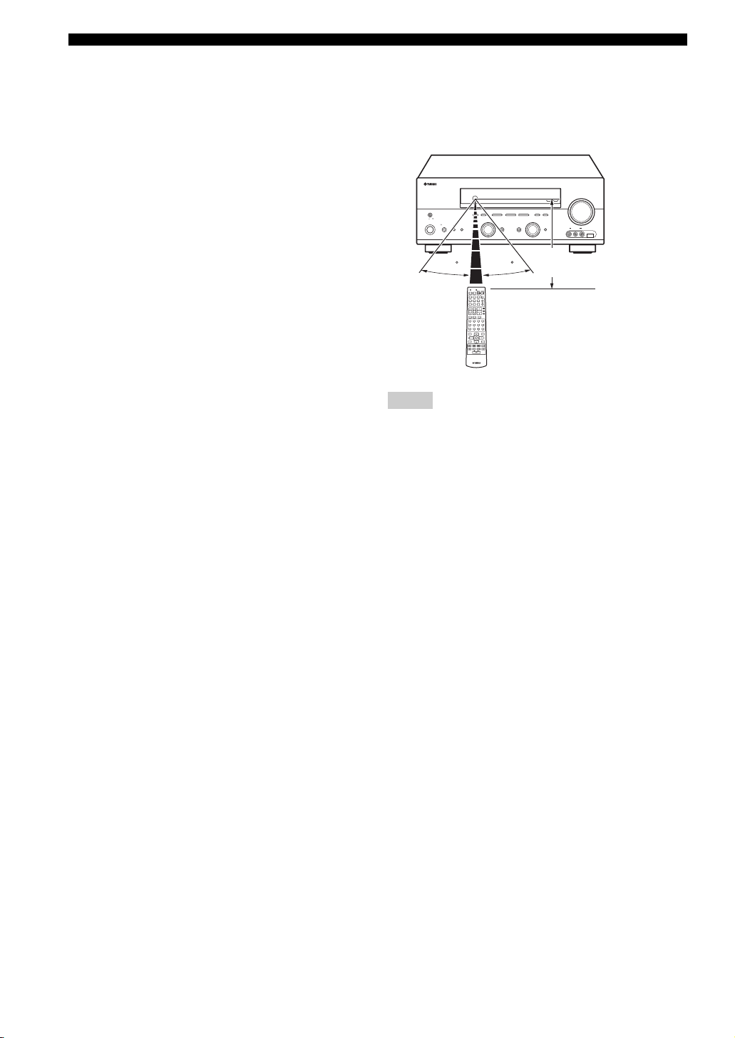
■ Using the remote control
The remote control transmits a directional infrared ray.
Be sure to aim the remote control directly at the remote
control sensor on this unit during operation.
VOLUME
ZONE 2
ZONE
ON/OFF
MASTER
ON OFF
MAIN ZONE
ON/OFF
FM/AM
PRESET/TUNING
A/B/C/D/E
l PRESET/TUNING h
EDIT
NEXT LEVEL
SEARCH MODE
DAB
PROGRAM
SPEAKERSPHONES
BA
EFFECT
SILENT CINEMA
30 30
TRANSMITCODE SET
STANDBY
POWER
POWERPOWER
AVTV
SLEEP
MD
CD-R
CD
MULTI CH IN
CBL
DVD DTV
TUNER
DOCK USB
V-AUX DVR
NET
AMP
SOURCE
TV VOL TV CH
VOLUME
TV
TV MUTE TV INPUT
MUTE
STEREO
MUSIC
ENTERTAIN
MOVIE
1
2
3
4
STANDARD
SELECT
EXTD SUR.
DIRECT ST.
5
6
7
8
SPEAKERS
ENHANCER
NIGHT
STRAIGHT
9
0
10
ENT.
EFFECT
PRESET/CH
SET MENU
LEVEL
MENUTITLE
SRCH MODE
BAND
ENTER
A/B/C/D/E
DISPLAYRETURN
ON SCREENDAB MEMORY
REC
AUDIO
USB
NET RADIO
PC/MCX
FREQ/TEXT EONSTARTPTY SEEKMODE
Notes
• Do not spill water or other liquids on the remote control.
• Do not drop the remote control.
• Do not leave or store the remote control in the following types
of conditions:
– places of high humidity, such as near a bath
– places of high temperatures, such as near a heater or stove
– places of extremely low temperatures
– dusty places
CONTROL
TUNING MODE
MEMORY
MAN'L/AUTO FM
AUTO/MAN'L
DISPLAY
INPUT
INPUT MODETONE CONTROLSTRAIGHT
MULTI CH
INPUT
VIDEO L AUDIO R
Approximately 6 m
USBVIDEO AUX
K DISPLAY
Displays various information of the service currently
being broadcast when this unit is in the DAB tuning mode
(see page 63).
8 En
Page 11
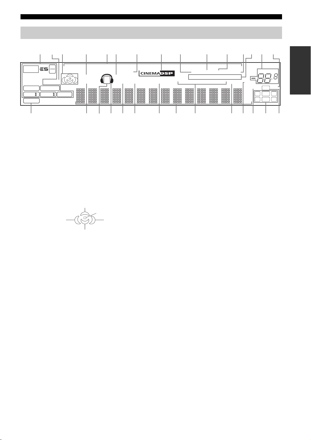
Front panel display
CONTROLS AND FUNCTIONS
2
13 4567 8 B
p
NET
t
MATRIX DISCRETE
q
EX
q
PL x
PCM
96
24
ENHANCER
q
DIGITAL
q
PL
q
PL
USB
VIRTUAL
STANDARD
1 Decoder indicators
The respective indicator lights up when any of the
decoders of this unit functions.
2 ENHANCER indicator
Lights up when the Compressed Music Enhancer mode is
turned on (see page 37).
3 Sound field indicators
Light up to indicate the active DSP sound fields.
p
DVR
p
V-AUXpDTV/CBL
DOCK
SILENT CINEMA
SP
ZONE2 NIGHT
A B
GKILM O
H
J
HiFi DSP
p
DVD
p
9 AUTO indicator
Lights up when this unit is in the automatic tuning mode
(see page 46).
0 TUNED indicator
Lights up when this unit is tuned into a station
(see page 46).
A STEREO indicator
• Lights up when this unit is receiving a strong signal for
0A9D
MD/CD-RpTUNER
TUNED
AUTO
DAB
STEREO
SECONDARY DRC PRESET
PSHOLD RT
EON
PTYPTY
CT
an FM stereo broadcast while the AUTO indicator is lit
Presence DSP sound field
Listening position
Surround left
DSP sound field
Surround back DSP sound field
Surround right
DSP sound field
4 VIRTUAL indicator
Lights up when Virtual CINEMA DSP is active (see
page 44).
5 Input source indicators
The corresponding cursor lights up to show the currently
selected input source.
6 SILENT CINEMA indicator
Lights up when headphones are connected and a sound
field program is selected (see page 34).
7 DOCK indicator
Lights up when you station your iPod in a YAMAHA iPod
universal dock (such as YDS-10 sold separately)
connected to the DOCK terminal of this unit
(see page 21).
8 CINEMA DSP indicator
Lights up when you select a CINEMA DSP sound field
program (see page 71).
(see page 46).
• Lights up when this unit is receiving a stereo DAB
service.
B MEMORY indicator
Flashes to show that a station or a DAB service can be
stored (see pages 48 and 60).
C DAB indicators
Indicate the current DAB tuning status when this unit is in
the DAB tuning mode (see pages 58 to 69).
D VOLUME level indicator
Indicates the current volume level.
E DUAL indicator
Lights up when dual monaural signals are being input to
this unit when this unit is in the DAB tuning mode.
F PCM indicator
Lights up when this unit is reproducing PCM (Pulse Code
Modulation) digital audio signals.
G STANDARD indicator
Lights up when the “SUR. STANDARD” or “SUR.
ENHANCED” program is selected.
H SP A B indicators
Light up according to the set of front speakers selected.
p
CD
MEMORY
SLEEP
MUTE
ft
mS
dB
C
QP
VOLUME
96/24
LFE
LCR
SL SB SR
E
DUAL
INTRODUCTION
dB
SRNF
9 En
Page 12

CONTROLS AND FUNCTIONS
I Headphones indicator
Lights up when headphones are connected.
J ZONE2 indicator
Lights up when Zone 2 is turned on (see page 102).
K NIGHT indicator
Lights up when you select a night listening mode
(see page 34).
L HiFi DSP indicator
Lights up when you select a HiFi DSP sound field
program (see page 72).
M Multi-information display
Shows the name of the current sound field program and
other information when adjusting or changing settings.
N Radio Data System indicators
The corresponding indicator lights up to show the type
of the Radio Data System information.
EON
Lights up when the EON data service is being
received.
PTY HOLD
Lights up while searching for the Radio Data System
stations in the PTY SEEK mode.
O SLEEP indicator
Lights up while the sleep timer is on (see page 35).
P MUTE indicator
Flashes while the MUTE function is on (see page 34).
Q 96/24 indicator
Lights up when a DTS 96/24 signal is input to this unit.
R Input channel indicators
Indicate the channel components of the current digital
input signal.
S LFE indicator
Lights up when the input signal contains the LFE signal.
10 En
Page 13
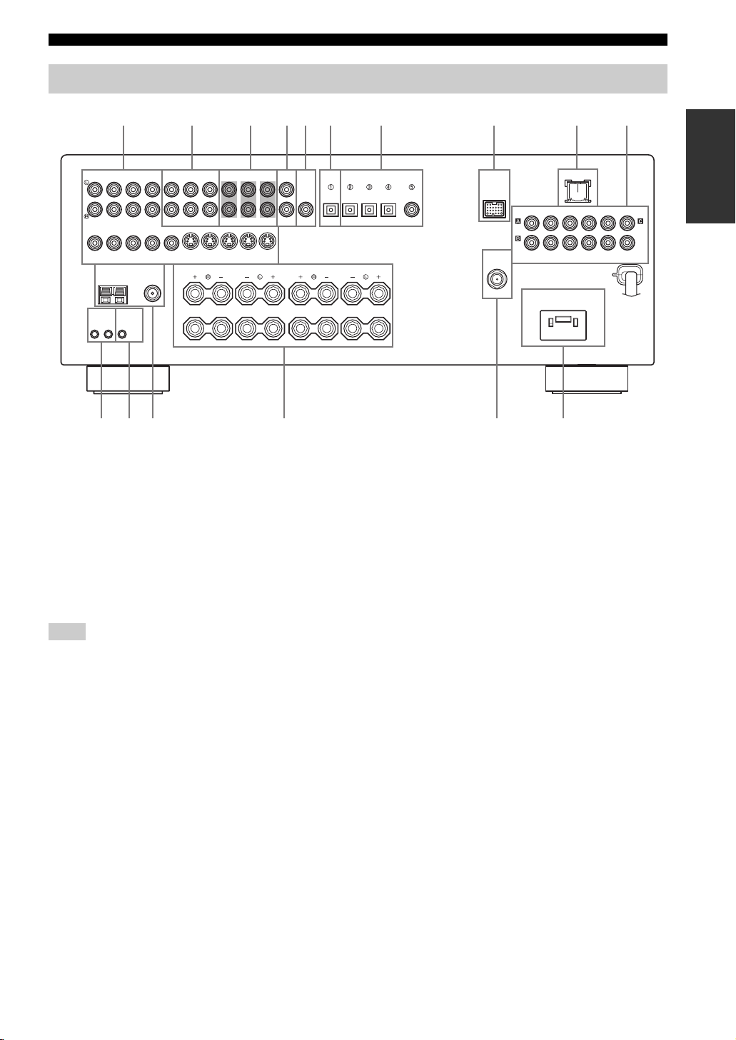
Rear panel
CONTROLS AND FUNCTIONS
AUDIO AUDIO OUTPUT DIGITAL INPUT
IN
CD
(PLAY)
IN OUT
DTV/CBL
DVR DVD DTV/CBL
DVD
VIDEO S VIDEO
TUNER SPEAKERS
AM
ANT
GND
REMOTE CONTROL
+12V
OUTIN
15mA MAX.
MONITOR
OUT
FM ANT
75Ω
UNBAL.
A
OUT
B
ABC
MD/
OUT
CD-R
FRONT ZONE 2
(REC)
MULTI CH INPUT
SURROUND
IN OUT
DVR
FRONT
CENTER
WOOFER
MONITOR
SUB
OUT
D
WOOFER
SUB
CENTER
DIGITAL
OUTPUT
OPTICAL OPTICAL
SURROUND
1 Video component jacks
See pages 17 and 18 for connection information.
2 Audio component jacks
See page 20 for connection information.
3 MULTI CH INPUT jacks
See page 23 for connection information.
4 ZONE 2 OUTPUT jacks
See page 101 for connection information.
Note
These jacks output analog signals only.
5 SUBWOOFER OUTPUT jack
See page 13 for connection information.
6 DIGITAL OUTPUT jack
See page 20 for connection information.
7 DIGITAL INPUT jacks
See pages 18 and 20 for connection information.
8 DOCK terminal
Use to connect a YAMAHA iPod universal dock (such as
YDS-10 sold separately) where your iPod can be
stationed.
See page 21 for connection information.
P
COMPONENT VIDEO
AC OUTLET
SWITCHED
9 07654321
LANDOCK
RPBY
MONITOR OUT
DVD DVD
SURROUND BACK
8
DTV/CBLMD/CD-RMD/CD-R
COAXIAL
DAB
75 Ω UNBAL.
DVD
DTV/
CBL
E F
9 LAN port
Use to connect a network cable for network connections.
See page 22 for connection information.
0 COMPONENT VIDEO jacks
See pages 17 and 18 for connection information.
A REMOTE jacks
See page 101 for details.
B CONTROL OUT jack
This is a control expansion terminal for custom
installation.
C Antenna terminals
See page 24 for connection information.
D Speaker terminals
See page 13 for connection information.
E DAB antenna terminal
See page 25 for connection information.
F AC OUTLET (SWITCHED)
Use to supply power to your other audiovisual
components.
See page 26 for details.
INTRODUCTION
PRPBY
DVR
11 En
Page 14
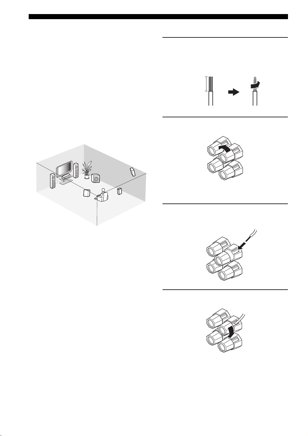
CONNECTIONS
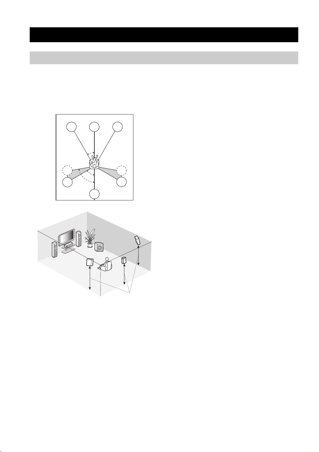
Placing speakers
CONNECTIONS
The speaker layout below shows the standard ITU-R*
speaker setting. You can use it to enjoy CINEMA DSP and
multi-channel audio sources.
*
ITU-R is the radio communication sector of the ITU
(International Telecommunication Union).
FL
SL
SL
C
30˚
60˚
80˚
SB
FR
SR
SR
FR
FL
SW
SR
C
SL
SB
1.8 m (6 ft)
Front left and right speakers (FL and FR)
The front speakers are used for the main source sound plus
effect sounds. Place these speakers at an equal distance
from the ideal listening position. The distance of each
speaker from each side of the video monitor should be the
same.
Center speaker (C)
The center speaker is for the center channel sounds
(dialog, vocals, etc.). If for some reason it is not practical
to use a center speaker, you can do without it. Best results,
however, are obtained with the full system. Place the
center speaker centrally between the front speakers and as
close to the monitor as possible, such as directly over or
under it.
Surround left and right speakers (SL and SR)
The surround speakers are used for effect and surround
sounds. Place these speakers behind your listening
position, facing slightly inwards, about 1.8 m (6 ft) above
the floor.
Surround back speaker (SB)
The surround back speaker supplements the surround
speakers and provides more realistic front-to-back
transitions. Place this speaker directly behind the listening
position and at the same height as the surround speakers.
Subwoofer (SW)
The use of a subwoofer with a built-in amplifier, such as
the YAMAHA Active Servo Processing Subwoofer
System, is effective not only for reinforcing bass
frequencies from any or all channels, but also for high
fidelity reproduction of the LFE (low-frequency effect)
channel included in Dolby Digital and DTS sources. The
position of the subwoofer is not so critical, because low
bass sounds are not highly directional. But it is better to
place the subwoofer near the front speakers. Turn it
slightly toward the center of the room to reduce wall
reflections.
12 En
Page 15
CONNECTIONS
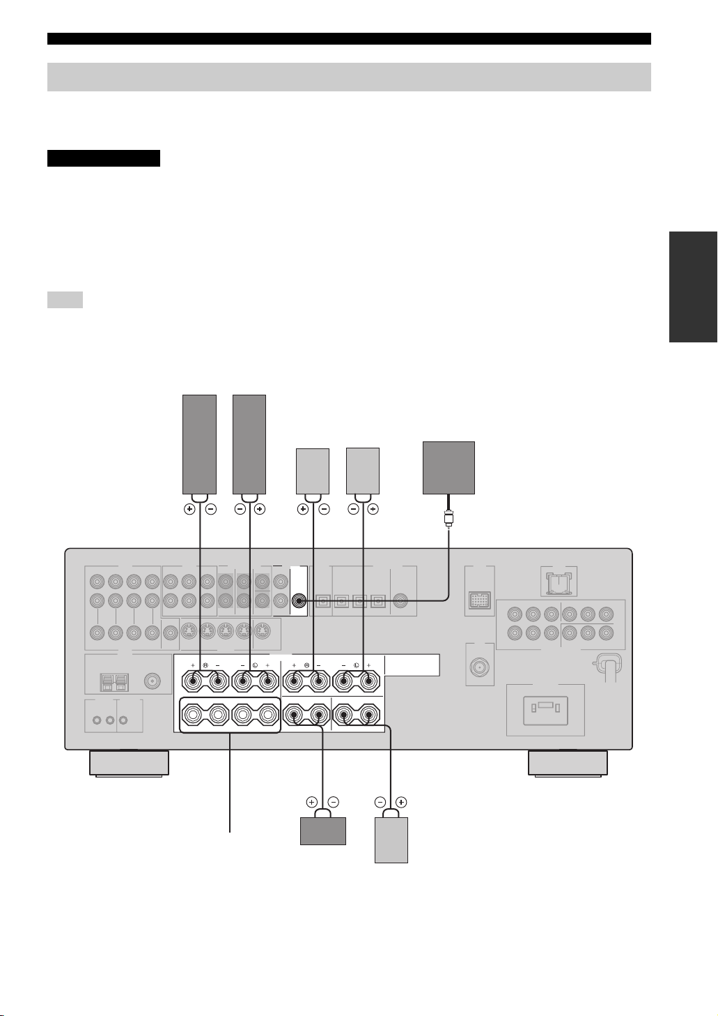
Connecting speakers
Be sure to connect the left channel (L), right channel (R), “+” (red) and “–” (black) properly. If the connections are faulty,
no sound will be heard from the speakers, and if the polarity of the speaker connections is incorrect, the sound will be
unnatural and lack bass.
CAUTION
• Before connecting the speakers, make sure that this unit is turned off (see page 28).
• Do not let the bare speaker wires touch each other or do not let them touch any metal part of this
unit. This could damage this unit and/or speakers.
• Use magnetically shielded speakers. If this type of speakers still creates the interference with the
monitor, place the speakers away from the monitor.
• If you are to use 6 ohm speakers, be sure to set “SP IMP.” to “6ΩMIN” before using this unit (see
page 27). 4 ohm speakers can be also used as the front speakers (see page 95).
Note
A speaker cord is actually a pair of insulated cables running side by side. Cables are colored or shaped differently, perhaps with a stripe,
groove or ridge. Connect the striped (grooved, etc.) cable to the “+” (red) terminals of this unit and your speaker. Connect the plain cable
to the “–” (black) terminals.
Front speakers (A)
LeftRight
PREPARATION
Surround speakers
Subwoofer
LeftRight
1 2 4 57
OUTPUT
SUB
WOOFER
FRONT
A
B
SPEAKERS
CENTER SURROUND BACK
SURROUND
Front
speakers
(B)
Center
speaker
63
Surround back
speaker
13 En
Page 16
CONNECTIONS
FRONT terminals
Connect one or two sets of front speakers (1, 2) to these
terminals. If you use only one front speaker system,
connect it to the FRONT A or B terminal.
CENTER terminals
Connect a center speaker (3) to these terminals.
SURROUND terminals
Connect surround speakers (4, 5) to these terminals.
SURROUND BACK terminals
Connect a surround back speaker (6) to these terminals.
SUBWOOFER OUTPUT jack
Connect a subwoofer with a built-in amplifier (7) (such as
the YAMAHA Active Servo Processing Subwoofer
System) to this jack.
1
7
2
3
5
4
6
■ Connecting the speaker cable
1 Remove approximately 10 mm of insulation
from the end of each speaker cable and then
twist the exposed wires of the cable together
to prevent short circuits.
10 mm
2 Loosen the knob.
Red: positive (+)
Black: negative (–)
Speaker layout
3 Insert one bare wire into the hole on the side
of each terminal.
4 Tighten the knob to secure the wire.
14 En
Page 17
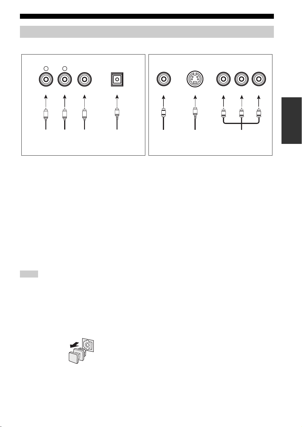
Information on jacks and cable plugs
Audio jacks and cable plugs Video jacks and cable plugs
CONNECTIONS
AUDIO
L
L
Left and right
analog audio
cable plugs
R
(Red)(White) (Orange) (Yellow) (Green) (Blue) (Red)
R
DIGITAL AUDIO
COAXIAL
C
Coaxial
digital audio
cable plug
DIGITAL AUDIO
OPTICAL
O
Optical
digital
audio cable
plug
■ Audio jacks
This unit has three types of audio jacks. Connection
depends on the availability of audio jacks on your other
components.
AUDIO jacks
For conventional analog audio signals transmitted via left
and right analog audio cables. Connect red plugs to the
right jacks and white plugs to the left jacks.
DIGITAL AUDIO COAXIAL jacks
For digital audio signals transmitted via coaxial digital
audio cables.
DIGITAL AUDIO OPTICAL jacks
For digital audio signals transmitted via optical digital
audio cables.
Notes
• You can use the digital jacks to input PCM, Dolby Digital and
DTS bitstreams. When you connect components to both the
COAXIAL and OPTICAL jacks, priority is given to the signals
input at the COAXIAL jack. All digital input jacks are
compatible with 96-kHz sampling digital signals.
• Pull out the cap from the optical jack before you connect the
fiber optic cable. Do not discard the cap. When you are not
using the optical jack, be sure to put the cap back in place. This
cap protects the jack from dust.
VIDEO S VIDEO
V
Composite
video cable
plug
cable plug
S
S-video
COMPONENT VIDEO
Y PBP
PB
Y
Component
video cable
plugs
R
P
R
■ Video jacks
This unit has three types of video jacks. Connection
depends on the availability of input jacks on your video
monitor.
VIDEO jacks
For conventional composite video signals transmitted via
composite video cables.
S VIDEO jacks
For S-video signals, separated into the luminance (Y) and
chrominance (C) video signals transmitted on separate
wires of S-video cables.
COMPONENT VIDEO jacks
For component video signals, separated into the
luminance (Y) and chrominance (P
transmitted on separate wires of component video cables.
y
When “VIDEO CONV.” is set to “ON” (see page 92), the video
signals input at the VIDEO and S VIDEO jacks are converted and
output at the VIDEO, S VIDEO and COMPONENT VIDEO
jacks interchangeably.
B, PR) video signals
PREPARATION
15 En
Page 18
CONNECTIONS
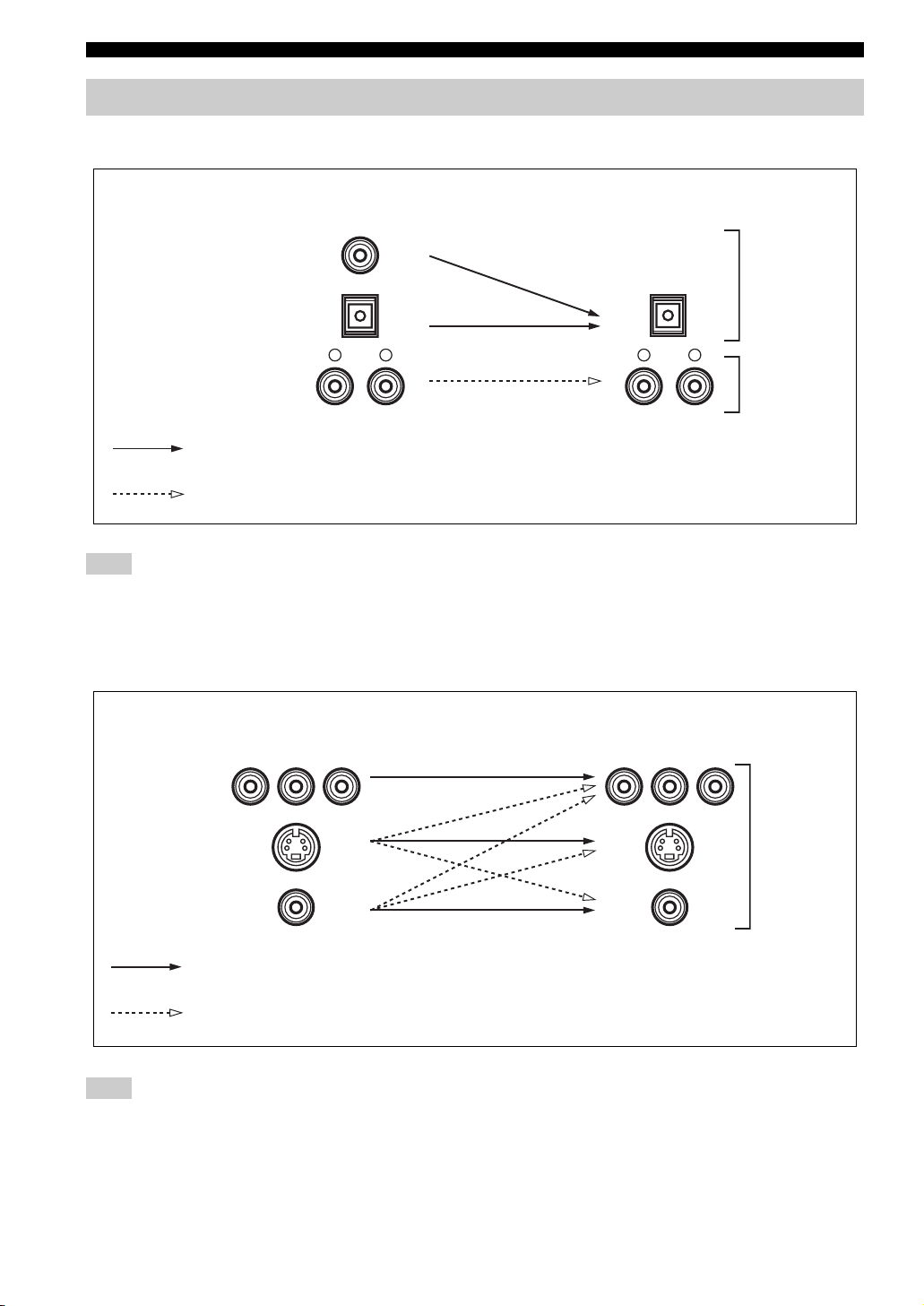
Audio and video signal flow
■ Audio signal flow for AUDIO OUT (REC)
Input
Output
AUDIO OUT (REC)
DIGITAL AUDIO
COAXIAL
Digital audio
DIGITAL AUDIO
OPTICAL
RLRL
AUDIO
Digital output
Analog output
Analog audio
Note
This unit handles digital and analog signals independently. Thus, audio signals input at the analog jacks are output only at the analog
AUDIO OUT (REC) jacks. Likewise, audio signals input at the DIGITAL INPUT (OPTICAL or COAXIAL) jacks are output only at the
DIGITAL OUTPUT jack.
■ Video signal flow for MONITOR OUT
Input
Y PBP
R
Output
(MONITOR OUT)
Y PBP
R
COMPONENT
VIDEO
S VIDEO
Analog video
VIDEO
Through
Video conversion when “VIDEO CONV.” is set to “ON” (see page 92)
Note
If video signals are input at the COMPONENT VIDEO, S VIDEO and VIDEO jacks simultaneously when “VIDEO CONV.” is set to
“ON”, the priority order of the input signals is as follows:
COMPONENT VIDEO > S VIDEO > VIDEO
16 En
Page 19
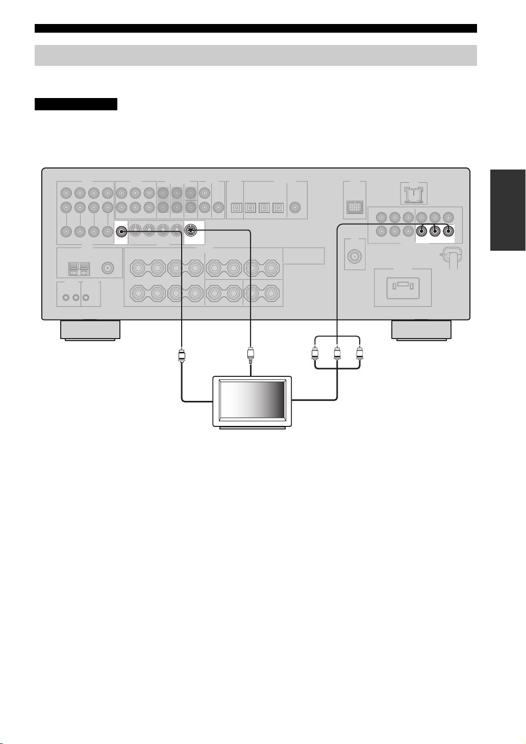
CONNECTIONS
Connecting a TV
Connect your TV to the VIDEO MONITOR OUT jack, the S VIDEO MONITOR OUT jack or the COMPONENT
VIDEO MONITOR OUT jacks of this unit.
CAUTION
Do not connect this unit or other components to the AC power supply until all connections between
components are complete.
PRPBY
PREPARATION
MONITOR
VIDEO S VIDEO
OUT
MONITOR
OUT
V
Video in
S
S-video in
TV
Y
Component video in
MONITOR OUT
COMPONENT VIDEO
PRPB
17 En
Page 20
CONNECTIONS
Connecting a DVD player, a DVD recorder, a VCR or an STB
Connect your DVD player, DVD recorder, VCR or STB (set-top box) using the same type of video connections as those
made for your TV (see page 17). The cable TV receiver and the satellite receiver are examples of the STB.
CAUTION
Do not connect this unit or other components to the AC power supply until all connections between
components are complete.
Notes
• When “VIDEO CONV.” is set to “OFF” (see page 92), be sure to make the same type of video connections as those made for your TV
(see page 17). For example, if you connected your TV to the VIDEO MONITOR OUT jack of this unit, connect your other
components to the VIDEO jacks.
• When “VIDEO CONV.” is set to “ON” (see page 92), the converted video signals are output only at the MONITOR OUT jacks. When
recording a source, you must make the same type of video connections between each component.
• To make a digital connection to a component other than the default component assigned to each DIGITAL INPUT or DIGITAL
OUTPUT jack, select the corresponding setting for “OPTICAL OUT”, “OPTICAL IN”, or “COAXIAL IN” in “I/O ASSIGNMENT”
(see page 87).
• If you connect your DVD player to both the DIGITAL INPUT (OPTICAL) and the DIGITAL INPUT (COAXIAL) jacks, priority is
given to the signals input at the DIGITAL INPUT (COAXIAL) jack.
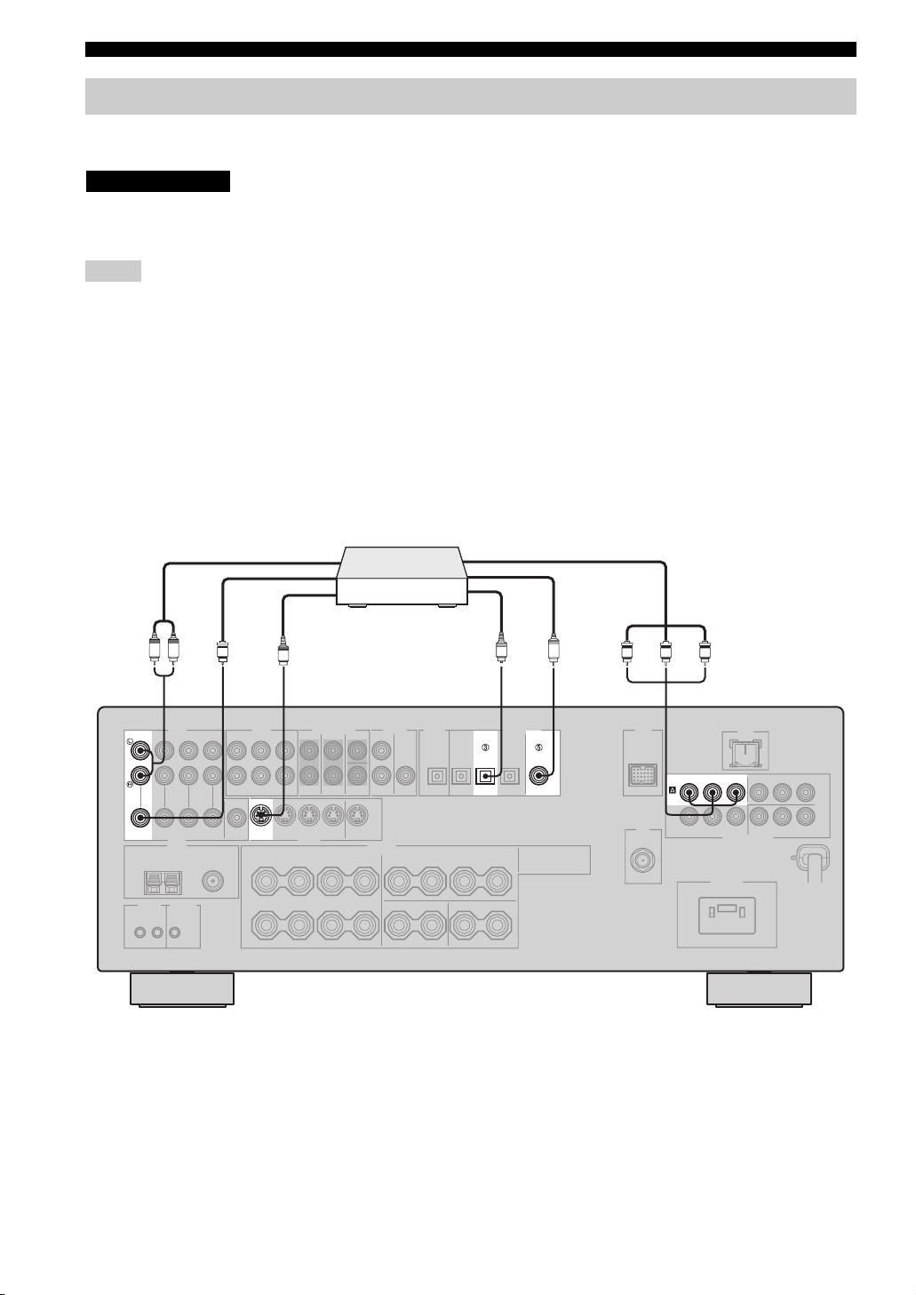
■ Connecting a DVD player
Audio out
DVD player
LR
V
AUDIO DIGITAL INPUT
DVD DVD
VIDEO S VIDEO
Video out
S
S-video out
O
DVD DVD
OPTICAL
Component video out
C
Optical audio out
Coaxial audio out
COAXIAL
P
RPBY
RPBY
DVD
P
COMPONENT VIDEO
18 En
Page 21
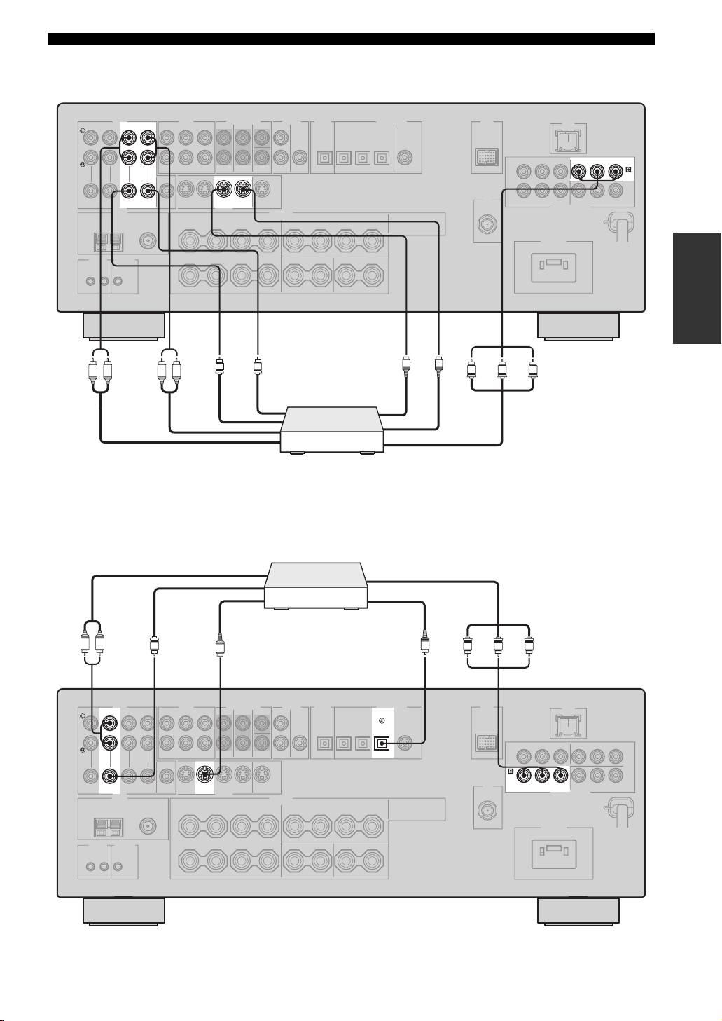
■ Connecting a DVD recorder or a VCR
AUDIO
CONNECTIONS
PRPBY
DVR
IN OUT
DVR
VIDEO S VIDEO
LR LR
Audio out
Audio in
■ Connecting an STB
Video out
IN OUT
V
DVR
V
Video in
Cable TV receiver or
satellite receiver
DVD recorder or
VCR
COMPONENT VIDEO
PREPARATION
S
S
S-video in
S-video out
PRPBY
Component video out
Component video out
LR
DTV/CBL DTV/CBL
V
Audio out
AUDIO DIGITAL INPUT
VIDEO S VIDEO
Video out
S
S-video out
OPTICAL
DTV/CBL
O
RPBY
P
Optical audio out
P
RPBY
DTV/
CBL
COMPONENT VIDEO
19 En
Page 22
CONNECTIONS
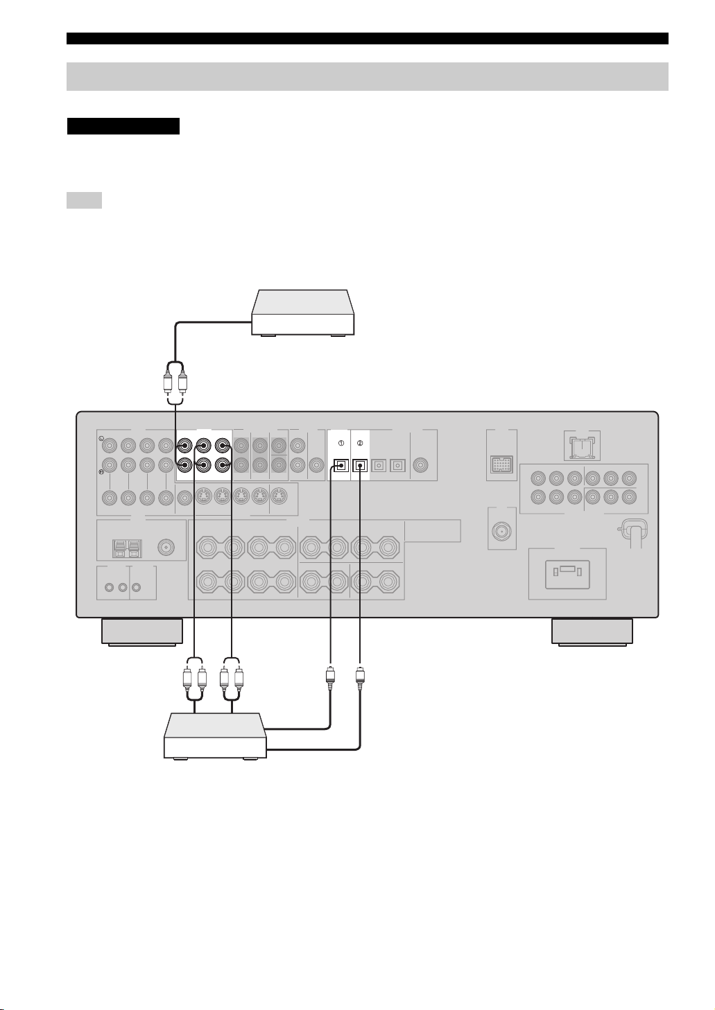
Connecting a CD player, an MD player or a tape deck
Connect your CD player, MD player or tape deck via analog and/or digital connections.
CAUTION
Do not connect this unit or other components to the AC power supply until all connections between
components are complete.
Note
To make a digital connection to a component other than the default component assigned to each DIGITAL INPUT or DIGITAL
OUTPUT jack, select the corresponding setting for “OPTICAL OUT”, “OPTICAL IN”, or “COAXIAL IN” in “I/O ASSIGNMENT”
(see page 87).
CD player
Audio out
LR
Audio out
AUDIO DIGITAL INPUT
MD/
IN
OUT
CD-R
CD
(REC)
(PLAY)
LR LR
Audio in
DIGITAL
OUTPUT
MD/CD-RMD/CD-R
OPTICAL OPTICAL
O
O
Optical audio in
MD recorder or
tape deck
Optical audio out
20 En
Page 23
CONNECTIONS
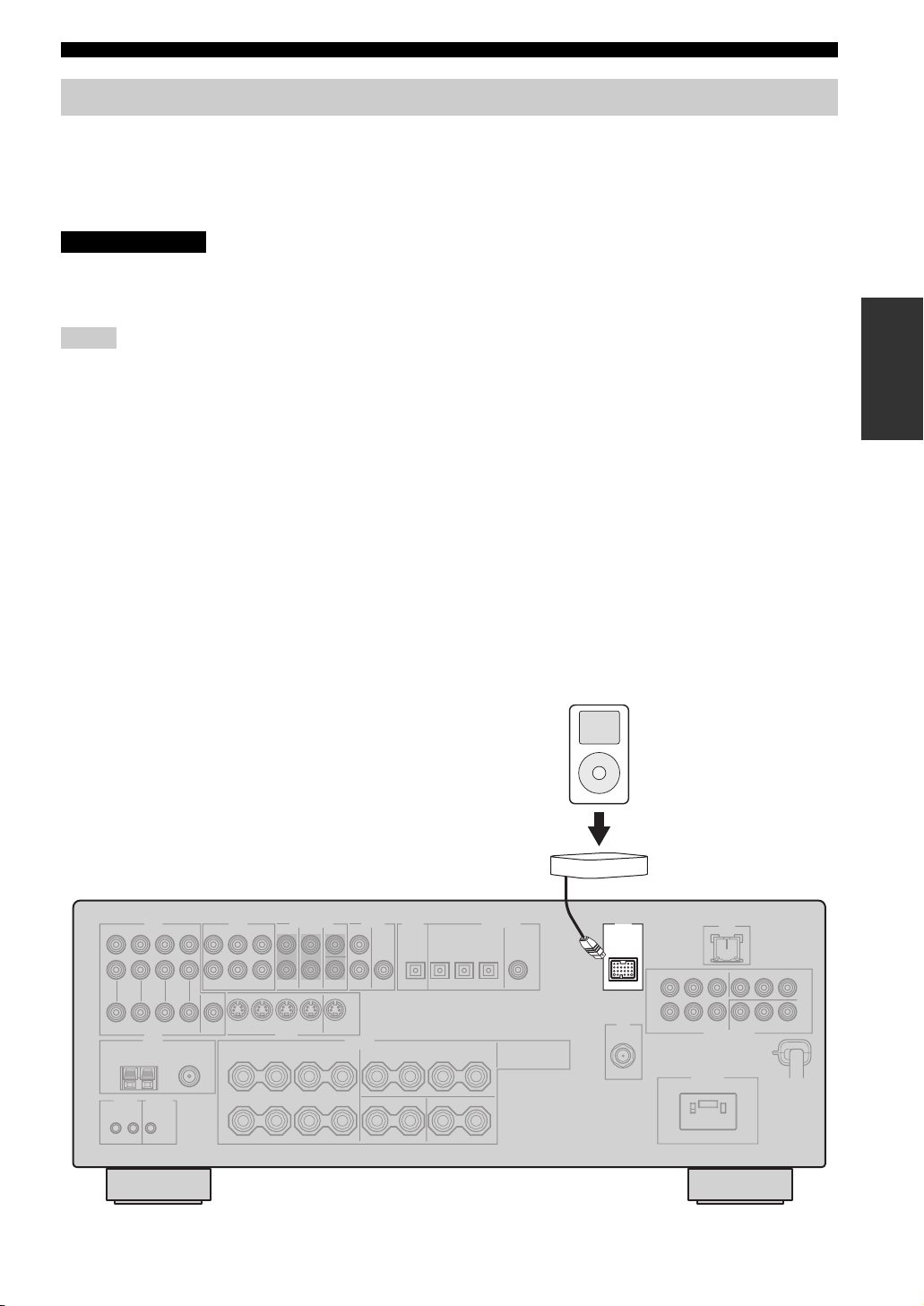
Connecting a YAMAHA iPod universal dock
This unit is equipped with the DOCK terminal on the rear panel that allows you to connect a YAMAHA iPod universal
dock (such as YDS-10 sold separately) where you can station your iPod and control playback of your iPod using the
supplied remote control. Connect a YAMAHA iPod universal dock (such as YDS-10 sold separately) to the DOCK
terminal on the rear panel of this unit using its dedicated cable. Once the connection is complete, station your iPod in the
YAMAHA iPod universal dock.
CAUTION
Do not connect this unit or other components to the AC power supply until all connections between
components are complete.
Notes
• Only iPod (Click and Wheel), iPod nano, and iPod mini are supported.
• You need a YAMAHA iPod universal dock (such as YDS-10 sold separately) and its dedicated cable compatible with the DOCK
terminal of this unit.
• Do not connect any iPod accessories (such as headphones, a wired remote control, or an FM transmitter) to your iPod when it is
stationed in a YAMAHA iPod universal dock (such as YDS-10 sold separately).
• Once your iPod is stationed in a YAMAHA iPod universal dock (such as YDS-10 sold separately) connected to the DOCK terminal of
this unit, this unit begins the signal transmission with your iPod.
• Unless your iPod is firmly stationed in a YAMAHA iPod universal dock (such as YDS-10 sold separately) connected to the DOCK
terminal of this unit, audio and/or video signals may not be output properly.
• Once the connection between your iPod and this unit is complete, “iPod connected” appears in the front panel display and the DOCK
indicator lights up in the front panel display. If the connection between your iPod and this unit fails, a status message appears in the
front panel display. For a complete list of connection status messages, see the iPod section in “TROUBLESHOOTING” on page 116.
• Only analog audio and video signals of your iPod are input at the DOCK terminal, and the analog audio signals can be output at the
analog AUDIO OUT (REC) jacks for recording.
• Your iPod battery is automatically charged when your iPod is stationed in a YAMAHA iPod universal dock (such as YDS-10 sold
separately) connected to the DOCK terminal of this unit as long as this unit is turned on.
• Depending on the type of iPod, you may need to insert one of the iPod adapters supplied with a YAMAHA iPod universal dock (such
as YDS-10 sold separately) into the dock slot before you station your iPod.
PREPARATION
YAMAHA iPod universal dock
(such as YDS-10 sold separately)
iPod
DOCK
21 En
Page 24
CONNECTIONS
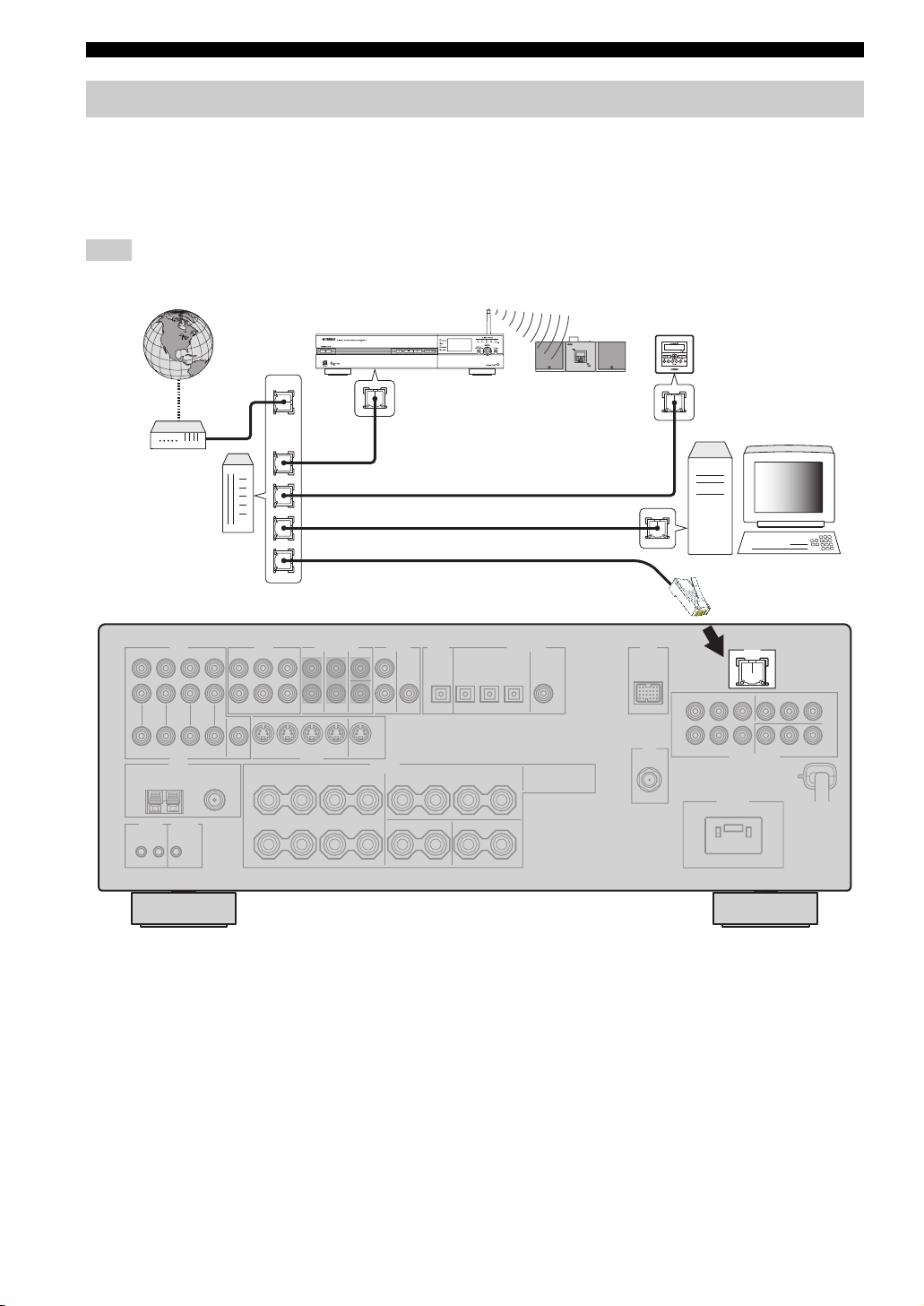
Connecting the network
To connect this unit to your network, plug one end of a network cable (CAT-5 or higher straight cable) into the LAN port
of this unit, and plug the other end into one of the LAN ports on your router that supports the DHCP (Dynamic Host
Configuration Protocol) server function. The following diagram shows a connection example where this unit is connected
to one of the LAN ports on a 4-port router. To enjoy music files saved on your PC and YAMAHA MCX-2000 or access
the Internet radio, each device must be connected properly in the network.
Note
If the DHCP server function on your router is disabled, you need to configure the network settings manually (see page 90).
YAMAHA MCX-2000
Modem
Internet
Router
WAN
YAMAHA MCX-C15
YAMAHA MCX-A10
(with optional
speakers)
LAN
Network cable
PC
LAN
22 En
Page 25
CONNECTIONS
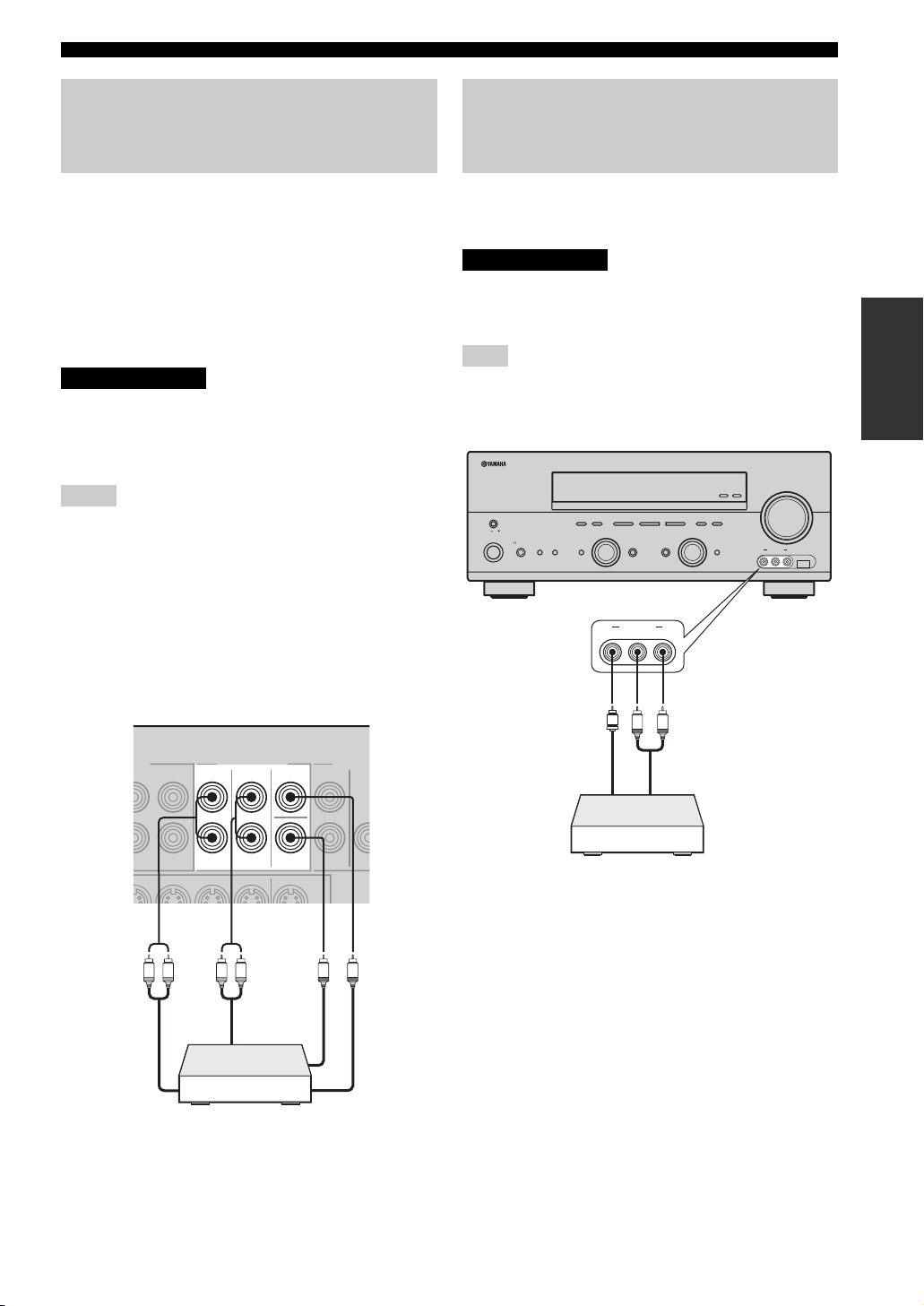
Connecting a multi-format player, an external decoder or a sound processor
This unit is equipped with 6 additional input jacks
(FRONT L/R, CENTER, SURROUND L/R and
SUBWOOFER) for discrete multi-channel input from a
multi-format player, external decoder or sound processor.
Connect the output jacks on your multi-format player,
external decoder or sound processor to the MULTI CH
INPUT jacks. Be sure to match the left and right output
jacks to the left and right input jacks for the front and
surround channels.
CAUTION
Do not connect this unit or other components to
the AC power supply until all connections
between components are complete.
Notes
• When you select the component connected to the MULTI CH
INPUT jacks as the input source (see page 38), this unit
automatically turns off the digital sound field processor, and
you cannot select sound field programs.
• This unit does not redirect signals input at the MULTI CH
INPUT jacks to accommodate for missing speakers. We
recommend that you connect at least a 5.1-channel speaker
system before using this feature.
• When headphones are used, only the signals input at the
FRONT L/R jacks are output at the PHONES jack.
Connecting a game console, a video camera or a portable audio player
Use the VIDEO AUX jacks on the front panel to connect a
game console, a video camera or a portable audio player to
this unit.
CAUTION
Be sure to turn off the volume of this unit and
other components before making connections.
Note
The audio signals input at the DOCK terminal takes priority over
the ones input at the VIDEO AUX jacks.
ZONE 2
ON/OFF
MASTER
ON OFF
MAIN ZONE
ON/OFF
SILENT CINEMA
FM/AM
PRESET/TUNING
A/B/C/D/E
NEXT
DABSEARCH MODE
PROGRAM
VIDEO AUX
VIDEO L AUDIO R
l PRESET/TUNING h
EDIT
SPEAKERSPHONES
BA
EFFECT
TUNING MODE
MEMORY
MAN'L/AUTO FM
AUTO/MAN'L
LEVEL
DISPLAY
INPUT
INPUT MODETONE CONTROLSTRAIGHT
MULTI CH
INPUT
VOLUME
ZONE
CONTROL
USBVIDEO AUX
VIDEO L AUDIO R
PREPARATION
L R L R
Front out
Multi-format player,
external decoder or
sound processor
MULTI CH INPUT
FRONT
Surround out
SURROUND
CENTER
SUB
WOOFER
V
LR
Video out
Audio out
Game console,
video camera or
portable audio player
Subwoofer out
Center out
23 En
Page 26
CONNECTIONS
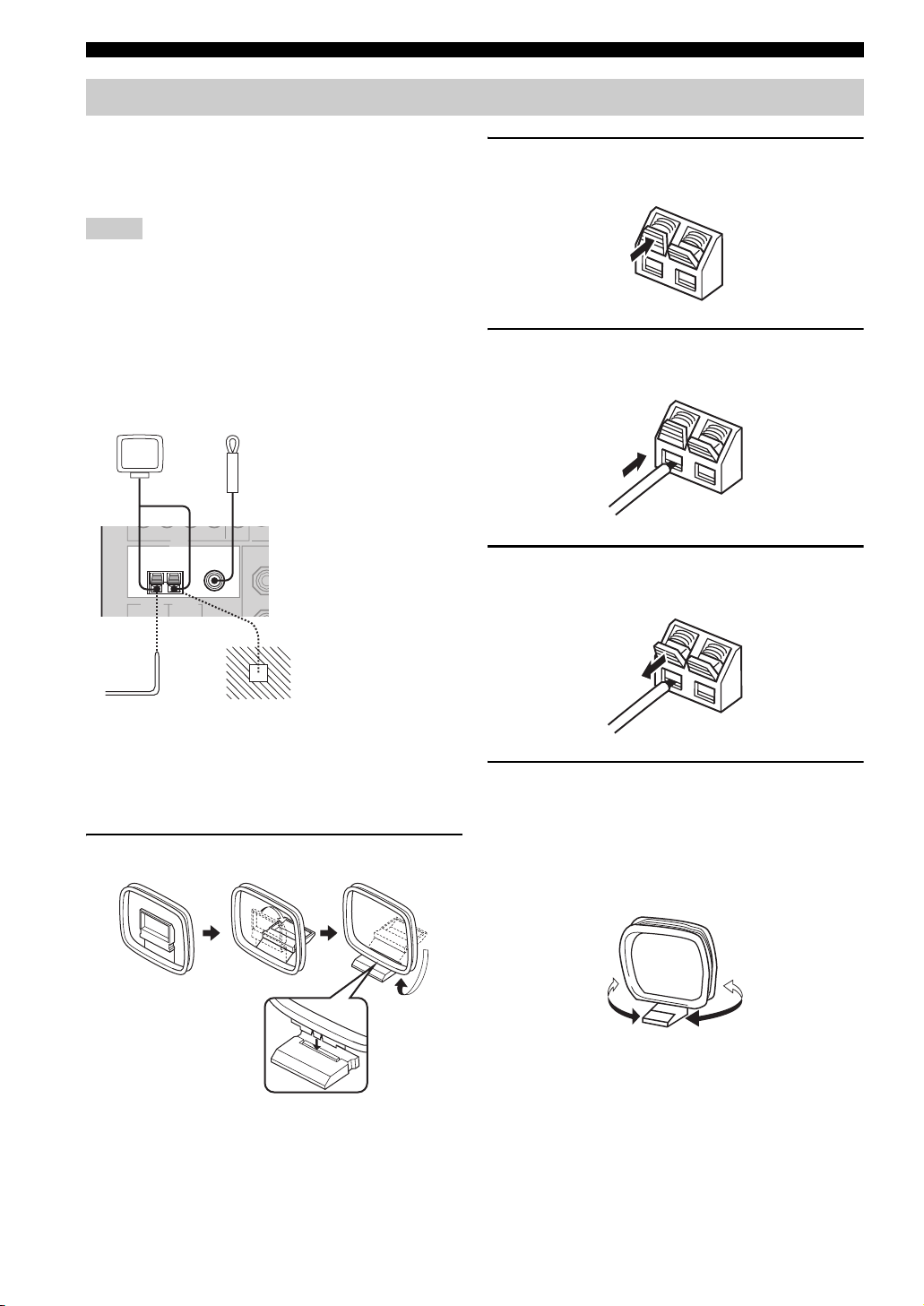
Connecting the FM and AM antennas
Both FM and AM indoor antennas are supplied with this
unit. In general, these antennas should provide sufficient
signal strength. Connect each antenna correctly to the
designated terminals.
Notes
• The AM loop antenna should be placed away from this unit.
• The AM loop antenna should always be connected, even if an
outdoor AM antenna is connected to this unit.
• A properly installed outdoor antenna provides clearer reception
than an indoor one. If you experience poor reception quality,
install an outdoor antenna. Consult the nearest authorized
YAMAHA dealer or service center about outdoor antennas.
AM loop antenna
(supplied)
Indoor FM antenna
(supplied)
TUNER
FM ANT
AM
ANT
75Ω
GND
UNBAL.
Ground (GND terminal)
For maximum safety and
minimum interference,
connect the antenna GND
terminal to a good earth
ground. A good earth ground
is a metal stake driven into
moist earth.
2 Press and hold the tab of the AM ANT
terminal.
3 Insert one of the AM loop antenna lead wires
into the AM ANT terminal.
4 Release the tab of the AM ANT terminal back
into place.
Outdoor AM antenna
Use a 5 to 10 m of vinyl-covered wire
extended from a window.
■ Connecting the AM loop antenna
1 Set up the AM loop antenna.
5 Repeat steps 2 through 4 to connect the
other lead wire to the GND terminal.
y
Once you have properly connected the AM loop antenna to this
unit, orient the AM loop antenna for the best reception when you
tune into AM stations.
24 En
Page 27
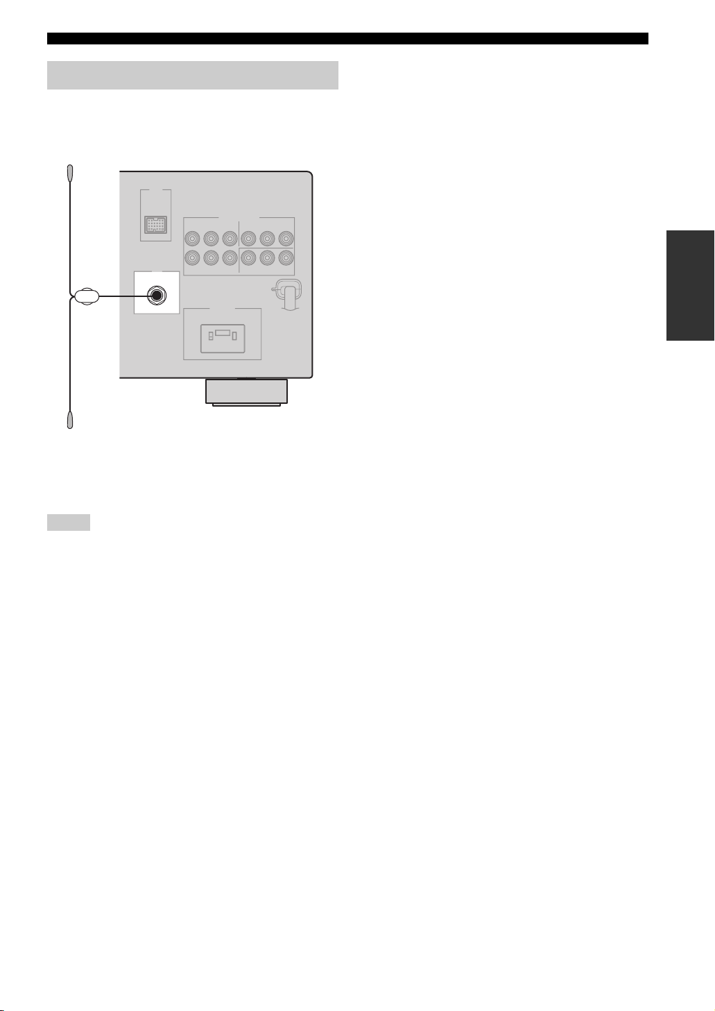
Connecting the DAB antenna
Connect the supplied indoor DAB antenna to the DAB
antenna terminal on the rear panel and attach the indoor
DAB antenna vertically on the wall.
DAB
75 Ω UNBAL.
Indoor DAB antenna
(supplied)
CONNECTIONS
PREPARATION
y
It is recommended that you use the tuning aid function (see
page 66) when you set up the indoor DAB antenna in order to
maximize DAB reception capability.
Notes
• Be sure to check the DAB coverage in your area in that not all
areas are currently being covered. For a list of nationwide DAB
statuses and worldwide DAB frequencies, check WorldDAB
online at “http://www.worlddab.org/”.
If the DAB signal is weak, use a commercially available outdoor
DAB antenna for better reception.
25 En
Page 28
CONNECTIONS
Connecting the power cable
Once all connections are complete, plug the power cable into the AC wall outlet.
AC OUTLETS
AC OUTLETS
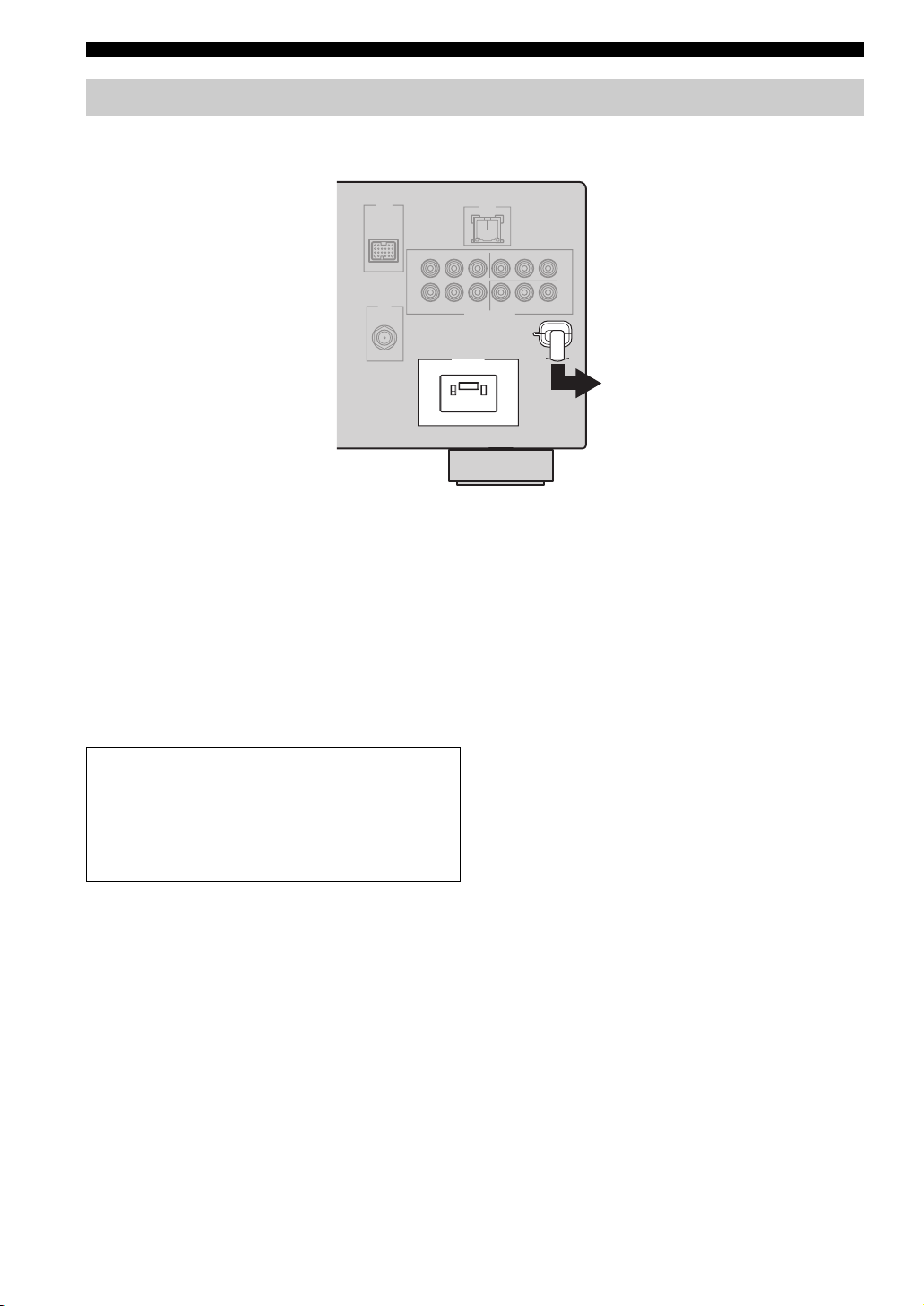
■ AC OUTLET (SWITCHED)
Use this outlet to supply power to any connected
components. Connect the power cable of another
component to this outlet. Power to this outlet is supplied
when the main zone or Zone 2 is turned on. However,
power to this outlet is cut off when the main zone and
Zone 2 are turned off or when MASTER ON/OFF on the
front panel is pressed and released outward to the OFF
position. For information on the maximum power, see
“SPECIFICATIONS” on page 123.
To the AC wall outlet
Memory back-up
The memory back-up circuit prevents the stored data
from being lost even if this unit is in the standby mode.
However, the stored data will be lost in case the power
cable is disconnected from the AC wall outlet or if the
power supply is cut off for more than one week.
26 En
Page 29
Setting the speaker impedance
CONNECTIONS
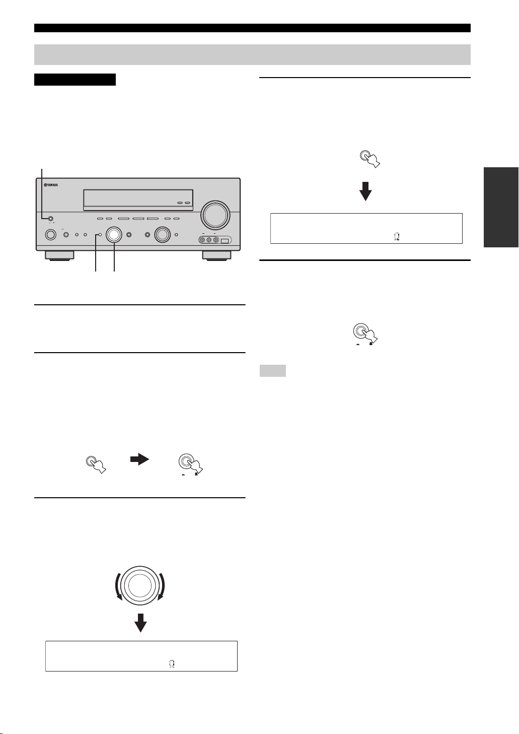
CAUTION
If you are to use 6 ohm speakers, set “SP IMP.” to
“6ΩMIN” as follows BEFORE using this unit. 4
ohm speakers can be also used as the front
speakers.
2,5
2,5
MAIN ZONE
MAIN ZONE
MASTER
MASTER
ON OFF
ON OFF
SPEAKERSPHONES
SPEAKERSPHONES
ON/OFF
ON/OFF
SILENT CINEMA
SILENT CINEMA
FM/AM
FM/AM
PRESET/TUNING
A/B/C/D/E
PRESET/TUNING
EDIT
EDIT
BA
BA
EFFECT
EFFECT
l PRESET/TUNING h
A/B/C/D/E
l PRESET/TUNING h
LEVEL
LEVEL
NEXT
NEXT
DABSEARCH MODE
DABSEARCH MODE
PROGRAM
PROGRAM
32,4
32,4
INPUT MODETONE CONTROLSTRAIGHT
INPUT MODETONE CONTROLSTRAIGHT
TUNING MODE
TUNING MODE
MEMORY
MEMORY
MAN'L/AUTO FM
AUTO/MAN'L
MAN'L/AUTO FM
AUTO/MAN'L
DISPLAY
DISPLAY
INPUT
INPUT
MULTI CH
MULTI CH
INPUT
INPUT
(U.S.A. model)
ZONE 2
ZONE
ZONE 2
ZONE
ON/OFF
CONTROL
ON/OFF
CONTROL
VIDEO L AUDIO R
VIDEO L AUDIO R
VOLUME
VOLUME
USBVIDEO AUX
USBVIDEO AUX
1 Make sure this unit is turned off.
See page 28 for details about turning on or off this
unit.
2 Press and hold STRAIGHT (EFFECT) on the
front panel and then press MASTER ON/OFF
inward to the ON position to turn on this unit.
This unit turns on, and the advanced setup menu
appears in the front panel display.
4 Press STRAIGHT (EFFECT) on the front
panel repeatedly to select “6ΩMIN”.
The following display appears in the front panel
display.
STRAIGHT
EFFECT
SP IMP.-6 MIN
5 Press MASTER ON/OFF on the front panel to
release it outward to the OFF position to save
the new setting and turn off this unit.
MASTER
ON OFF
Note
The setting you made is reflected next time you turn on this unit.
PREPARATION
While holding
down
STRAIGHT
EFFECT
MASTER
ON OFF
3 Rotate the PROGRAM selector on the front
panel to select “SP IMP.”.
The following display appears in the front panel
display.
PROGRAM
SP IMP.-8 MIN
27 En
Page 30
CONNECTIONS
AMP
SOURCE
TV
VOLUME
TV VOL TV CH
TRANSMITCODE SET
STANDBY
POWER
POWERPOWER
CD
AVTV
MULTI CH IN
SLEEP
CD-R
DVD DTV
MD
DOCK USB
CBL
NET
TUNER
V-AUX DVR
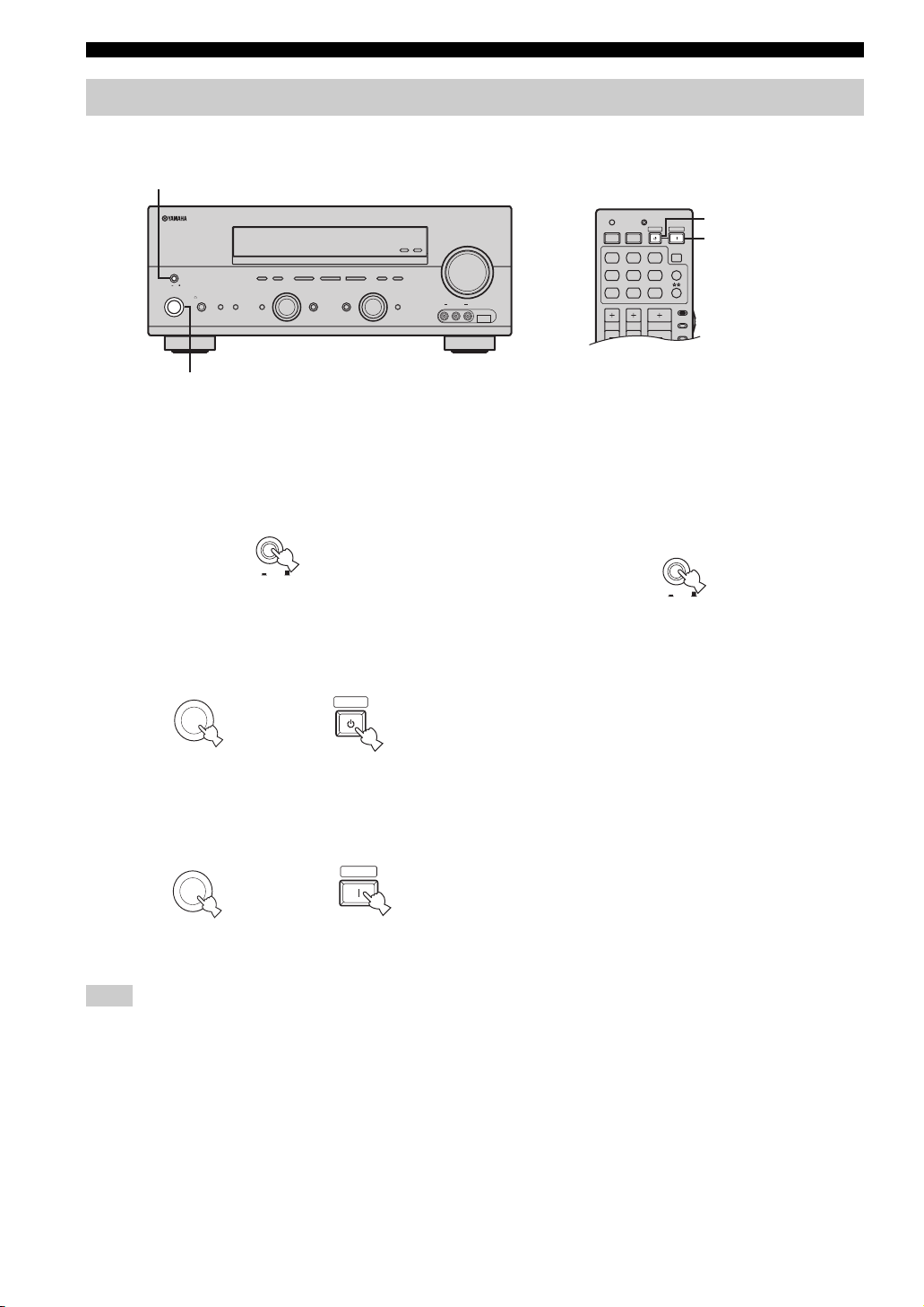
Turning on and off the power
When all connections are complete, turn on this unit.
MASTER ON/OFF
ZONE 2
ON/OFF
CONTROL
MASTER
ON OFF
MAIN ZONE
SPEAKERSPHONES
ON/OFF
SILENT CINEMA
MAIN ZONE ON/OFF
FM/AM
PRESET/TUNING
EDIT
DABSEARCH MODE
BA
EFFECT
PRESET/TUNING
A/B/C/D/E
l
NEXT
PROGRAM
TUNING MODE
MEMORY
h
MAN'L/AUTO FM
AUTO/MAN'L
LEVEL
DISPLAY
INPUT
INPUT MODETONE CONTROLSTRAIGHT
MULTI CH
INPUT
STANDBY
VOLUME
ZONE
USBVIDEO AUX
VIDEO L AUDIO R
POWER
■ Turning on this unit
Press MASTER ON/OFF on the front panel inward
to the ON position to turn on this unit.
MASTER
ON OFF
Front panel
• Press MAIN ZONE ON/OFF on the front panel (or
STANDBY on the remote control) to set the main zone
to the standby mode.
MAIN ZONE
ON/OFF
or
Front panel Remote control
• Press MAIN ZONE ON/OFF on the front panel (or
POWER on the remote control) to turn on the main
zone.
MAIN ZONE
ON/OFF
Front panel
or
STANDBY
POWER
Remote control
■ Turning off this unit
Press MASTER ON/OFF on the front panel to
release it outward to the OFF position to turn off
this unit.
MASTER
ON OFF
Front panel
Note
MAIN ZONE ON/OFF on the front panel as well as POWER and
STANDBY on the remote control are operational only when
MASTER ON/OFF is pressed inward to the ON position.
y
For details about turning on or off Zone 2, see page 102.
28 En
Page 31

BASIC SETUP
AMP
SOURCE
TV
VOLUME
TV VOL TV CH
TRANSMITCODE SET
STANDBY
POWER
POWERPOWER
CD
AVTV
MULTI CH IN
SLEEP
CD-R
DVD DTV
MD
DOCK USB
CBL
NET
TUNER
V-AUX DVR
MENUTITLE
SET MENU
LEVEL
DISPLAYRETURN
BAND
SRCH MODE
ON SCREENDAB MEMORY
A/B/C/D/E
ENTER
PRESET/CH
REC
STEREO
1
EFFECT
STANDARD
5
SPEAKERS
9
MUSIC
2
SELECT
6
ENHANCER
0
ENTERTAIN
3
EXTD SUR.
7
NIGHT
10
MOVIE
4
DIRECT ST.
8
STRAIGHT
ENT.
BASIC SETUP
The “BASIC SETUP” feature is a useful way to set up your system quickly and with minimal effort.
Notes
• Make sure you disconnect your headphones from this unit.
• If you wish to configure this unit manually using more precise adjustments, use the detailed parameters in “SOUND MENU” (see
page 82).
• Altering any parameters in “BASIC SETUP” resets all parameters manually adjusted in “SOUND MENU” (see page 82).
• Initial settings are indicated in bold under each parameter.
• Press RETURN on the remote control to return to the previous menu level.
4 Press ENTER to enter “BASIC SETUP”.
The following display appears in the OSD.
PREPARATION
2,13
1
3-12
1 Set the component selector switch to AMP.
AMP
SOURCE
TV
2 Press SET MENU to enter “SET MENU”.
The top “SET MENU” display appears in the OSD.
SET MENU
SET MENU
MENU
SRCH MODE
.;BASICSETUP
;MANUALSETUP
.;SIGNAL INFO
p
[ ]/[]:Up/Down
p
[ENTER]:Enter
PRESET/CH
ENTER
A/B/C/D/E
;BASIC SETUP
.ROOM: S >M L
SUBWOOFER;;;;YES
SPEAKERS;;;;6spk
SETUP:>OK CANCEL
p
[]/[]:Up/Down
p
[<]/[>]:Select
5 Press u / d to select “ROOM” and then j / i
to select the desired setting.
PRESET/CH
;BASIC SETUP
.ROOM: S >M L
ENTER
A/B/C/D/E
Select the size of the room where you have installed
your speakers. In general, the room sizes are defined
as follows:
Choices: S, M, L
S (small) 3.6 x 2.8m, 10m
M (medium) 4.8 x 4.0m, 20m
L (large) 6.3 x 5.0m, 30m
SUBWOOFER;;;;YES
SPEAKERS;;;;6spk
SETUP:>OK CANCEL
p
[]/[]:Up/Down
p
[<]/[>]:Select
2
2
2
3 Press u / d to select “BASIC SETUP”.
PRESET/CH
ENTER
A/B/C/D/E
29 En
Page 32

BASIC SETUP
6 Press d to select “SUBWOOFER” and then
j / i to select the desired setting.
PRESET/CH
;BASIC SETUP
ROOM: S >M L
ENTER
A/B/C/D/E
.SUBWOOFER;;;;YES
SPEAKERS;;;;6spk
SETUP:>OK CANCEL
p
[]/[]:Up/Down
p
[<]/[>]:Select
Choices: YES, NONE
• Select “YES” if you have a subwoofer in your
system.
• Select “NONE” if you do not have a subwoofer in
your system.
7 Press d to select “SPEAKERS” and then j / i
to select the number of speakers connected
to this unit.
PRESET/CH
;BASIC SETUP
ROOM: S >M L
ENTER
A/B/C/D/E
Choice Display Speakers
LL C R
2spk
3spk
4spk
5spk
LL C R
SL SB SR
SL SB SR
LL CR
SL SB SR
LL C R
SL SB SR
LL C R
SL SBSBSR
SUBWOOFER;;;;YES
.SPEAKERS;;;;6spk
SETUP:>OK CANCEL
p
[]/[]:Up/Down
p
[<]/[>]:Select
Front L/R
Front L/R, Center
Front L/R, Surround L/R
Front L/R, Center, Surround L/R
8 Press d to select “SETUP” and then j / i to
select the desired setting.
PRESET/CH
;BASIC SETUP
ROOM: S >M L
ENTER
A/B/C/D/E
SUBWOOFER;;;;YES
SPEAKERS;;;;6spk
. SETUP:>OK CANCEL
p
[]/[]:Up/Down
p
[<]/[>]:Select
Choices: OK, CANCEL
• Select “OK” to apply the settings you made.
• Select “CANCEL” to cancel the setup procedure
without making any changes.
y
You can also press SET MENU to cancel the setup
procedure.
9 Press ENTER to confirm your selection.
PRESET/CH
ENTER
A/B/C/D/E
If you selected “OK” in step 8, each speaker outputs a
test tone twice in turn. “CHECK:Test Tone” appears
in the OSD for a few seconds and then “CHECK
OK?” appears in the OSD.
;BASIC SETUP
ROOM: S >M L
SUBWOOFER;;;;YES
SPEAKERS;;;;6spk
SETUP:>OK CANCEL
.CHECK:Test Tone
[<]/[>]:Select
y
Check the speaker connections (see page 13) and adjust the
“SPEAKERS” settings back in step 7, if necessary.
;BASIC SETUP
ROOM: S >M L
SUBWOOFER;;;;YES
SPEAKERS;;;;6spk
SETUP:>OK CANCEL
.CHECK OK?;;;;YES
[<]/[>]:Select
30 En
6spk
LL C R
SL SB SR
Front L/R, Center, Surround L/R,
Surround back
Page 33

BASIC SETUP
10 Press j / i to select the desired setting.
PRESET/CH
ENTER
A/B/C/D/E
Choices: YES, NO
• Select “YES” to complete the setup procedure if
the test tone levels from each speaker were
satisfactory.
• Select “NO” to proceed to the speaker level
adjustment menu in step 12 to balance the output
level of each speaker.
;BASIC SETUP
ROOM: S >M L
SUBWOOFER;;;;YES
SPEAKERS;;;;6spk
SETUP:>OK CANCEL
.CHECK OK?;;;;YES
[<]/[>]:Select
11 Press ENTER to confirm your selection.
PRESET/CH
ENTER
A/B/C/D/E
• If you selected “YES” in step 10, the setup
procedure is completed and the display returns to
the top “SET MENU” display.
• If you selected “NO” in step 10, the speaker level
adjustment display appears in the front panel
display.
12 Press u / d to select a speaker and then j / i
to adjust the balance.
The selected speaker and the front left speaker (or the
surround left speaker) output a test tone in turn.
•Press i to increase the value.
•Press j to decrease the value.
PRESET/CH
;BASIC SETUP
-__________+
.FR;;;;;;;;;;
ENTER
A/B/C/D/E
C;;;;;;;;;;
SL;;;;;;;;;;
• Select “FR” to adjust the balance between the front
left and right speakers.
• Select “C” to adjust the balance between the front
left and center speakers.
• Select “SL” to adjust the balance between the front
left and surround left speakers.
• Select “SB” to adjust the balance between the
surround left and surround back speakers.
• Select “SR” to adjust the balance between the
surround left and surround right speakers.
• Select “SWFR” to adjust the balance between the
front left speaker and the subwoofer.
13 Press SET MENU to exit from “BASIC
SETUP”.
SET MENU
MENU
SRCH MODE
PREPARATION
31 En
Page 34

PLAYBACK
AMP
SOURCE
TV
VOLUME
TV VOL TV CH
TRANSMITCODE SET
STANDBY
POWER
POWERPOWER
CD
AVTV
MULTI CH IN
SLEEP
CD-R
DVD DTV
MD
DOCK USB
CBL
NET
TUNER
V-AUX DVR
TV MUTE TV INPUT
MUTE
MENUTITLE
SET MENU
LEVEL
DISPLAYRETURN
BAND
SRCH MODE
ON SCREENDAB MEMORY
A/B/C/D/E
ENTER
PRESET/CH
REC
AUDIO
STEREO
1
EFFECT
STANDARD
5
SPEAKERS
9
MUSIC
2
SELECT
6
ENHANCER
0
ENTERTAIN
3
EXTD SUR.
7
NIGHT
10
MOVIE
4
DIRECT ST.
8
STRAIGHT
ENT.
PLAYBACK
CAUTION
Extreme caution should be exercised when you play back CDs encoded in DTS. If you play back a CD
encoded in DTS on a DTS-incompatible CD player, you will only hear some unwanted noise that may
damage your speakers. Check whether your CD player supports CDs encoded in DTS. Also, check the
sound output level of your CD player before you play back a CD encoded in DTS.
3 Rotate the INPUT selector on the front panel
(or press one of the input selector buttons on
ZONE 2
ON/OFF
MASTER
ON OFF
MAIN ZONE
ON/OFF
SILENT CINEMA
FM/AM
PRESET/TUNING
A/B/C/D/E
EDIT
SPEAKERSPHONES
BA
EFFECT
l PRESET/TUNING h
NEXT
DABSEARCH MODE
PROGRAM
TUNING MODE
MEMORY
MAN'L/AUTO FM
AUTO/MAN'L
LEVEL
DISPLAY
INPUT
INPUT MODETONE CONTROLSTRAIGHT
MULTI CH
INPUT
VOLUME
ZONE
CONTROL
USBVIDEO AUX
VIDEO L AUDIO R
66,7 32 5
the remote control) to select the desired
input source.
INPUT
MD
CD
CD-R
or
CBL
DVD DTV
DOCK USB
V-AU X DVR
SLEEP
MULTI CH IN
TUNER
NET
3
2
2
5
1 Turn on the video monitor connected to this
unit.
2 Press SPEAKERS A or B on the front panel
(or set the component selector switch to
AMP and then press SPEAKERS on the
remote control repeatedly) to turn on the set
of front speakers you want to use.
Each time you press SPEAKERS A or B, the
respective set of front speakers are turned on or off.
SPEAKERS
BA
Front panel
or
32 En
AMP
SOURCE
TV
Remote control
SPEAKERS
9
7
Front panel Remote control
The name of the currently selected input source
appears in the front panel display and in the OSD for
a few seconds.
Available input sources
NET
DVR
SP
A
V-AUX DTV/CBL
USB
DVD AUTO
Currently selected
input source
p
DVD CD
MD/CD-R
TUNER
Currently selected
input mode
VOLUME
LR
dB
Notes
• To enjoy multi-channel sources in surround, connect the
source component via digital connection and set the input
mode to “AUTO” or “DTS” (see page 35).
• See page 42 for details about surround sound.
4 Start playback on the selected source
component or select a broadcast station.
• Refer to the operating instructions for the source
component.
• See page 46 for details about FM/AM tuning
instructions.
• See page 57 for details about DAB tuning
instructions.
Page 35

PLAYBACK
5 Rotate VOLUME on the front panel (or press
VOLUME +/– on the remote control) to adjust
the volume to the desired output level.
VOLUME
or
Front panel
VOLUME
Remote control
6 Press TONE CONTROL on the front panel
repeatedly to select “TREBLE” or “BASS”
and then rotate the PROGRAM selector to
adjust the corresponding frequency
response level.
TONE CONTROL
PROGRAM
7 Rotate the PROGRAM selector on the front
panel (or press one of the sound field
program selector buttons on the remote
control repeatedly) to select the desired
sound field program.
The name of the selected sound field program appears
in the front panel display and in the OSD.
See page 71 for details about sound field programs.
PROGRAM
Front panel
or
STEREO
MUSIC
ENTERTAIN
1
STANDARD
5
SPEAKERS
ENHANCER
9
Remote control
2
SELECT
6
0
3
EXTD SUR.
7
NIGHT
10
MOVIE
4
DIRECT ST.
8
STRAIGHT
ENT.
EFFECT
OPERATION
BASIC
NET
DVR
SP
A
V-AUX DTV/CBL
USB
TREBLE 0dB
p
DVD CD
MD/CD-R
TUNER
VOLUME
LR
dB
• Select “TREBLE” to adjust the high-frequency
response.
• Select “BASS” to adjust the low-frequency
response.
Notes
• Speaker and headphone adjustments are stored
independently.
• When “TONE BYPASS” is set to “AUTO” (see page 86),
and “BASS” and “TREBLE” are set to 0 dB, audio output
automatically bypasses the tone control circuitry of this
unit.
• If you increase or decrease the high-frequency or low-
frequency sound to an extreme level, the tonal quality of
the front speakers may not match that of the other
speakers.
• TONE CONTROL is not effective when the “DIRECT
STEREO” mode (see page 39) is selected or when the
component connected to the MULTI CH INPUT jacks is
selected as the input source (see page 38).
NET
DVR
SP
A
V-AUX DTV/CBL
USB
TV Sports
p
DVD CD
MD/CD-R
TUNER
VOLUME
LR
dB
Currently selected
sound field program
Notes
• Choose a sound field program based on your listening
preference, not merely on the name of the program.
• When you select an input source, this unit automatically
selects the last sound field program used with the
corresponding input source.
• Sound field programs cannot be selected when the
component connected to the MULTI CH INPUT jacks is
selected as the input source (see page 38).
• Sampling frequencies higher than 48 kHz (except for DTS
96/24 signals) are sampled down to 48 kHz and then sound
field programs are applied.
• To display information about the currently selected input
source in the OSD, see page 40 for details.
33 En
Page 36

USING AUDIO FEATURES
USING AUDIO FEATURES
Using SILENT CINEMA
SILENT CINEMA allows you to enjoy multi-channel
music or movie sound, including Dolby Digital and DTS
sources, through ordinary headphones. SILENT CINEMA
activates automatically whenever you connect headphones
to the PHONES jack while listening to a source with a
CINEMA DSP or HiFi DSP sound field program (see
page 71). When activated, the SILENT CINEMA
indicator lights up in the front panel display.
Notes
• SILENT CINEMA does not activate when the component
connected to the MULTI CH INPUT jacks is selected as the
input source (see page 38).
• SILENT CINEMA is not effective when the “DIRECT
STEREO” (see page 39), “2ch Stereo” (see page 39) or
“STRAIGHT” mode (see page 39) is selected.
Muting the audio output
Press MUTE on the remote control to mute the
audio output. Press MUTE again to resume the
audio output.
MUTE
y
• You can also rotate VOLUME on the front panel or VOLUME
+/– on the remote control to resume the audio output.
• You can adjust the muting level by using the “MUTING TYPE”
parameter in “SOUND MENU” (see page 86).
• The MUTE indicator flashes in the front panel display when the
audio output is muted and disappears from the front panel
display when the audio output is resumed.
Selecting the night listening mode
The night listening modes are designed to improve
listenability at lower volumes or at night. Choose either
“NIGHT:CINEMA” or “NIGHT:MUSIC” depending on
the type of material you are playing.
1 Set the component selector switch to AMP
and then press NIGHT on the remote control
repeatedly to select “NIGHT:CINEMA” or
“NIGHT:MUSIC”.
AMP
SOURCE
TV
Choices: NIGHT:CINEMA, NIGHT:MUSIC, OFF
• Select “NIGHT:CINEMA” when watching films to
reduce the dynamic range of film soundtracks and
make dialog easier to hear at lower volumes.
• Select “NIGHT:MUSIC” when listening to music
sources to preserve ease-of-listening for all sounds.
• Select “OFF” if you do not want to use this feature.
y
When a night listening mode is selected, the NIGHT
indicator lights up in the front panel display.
2 Press j / i on the remote control to adjust the
effect level while “NIGHT:CINEMA” or
“NIGHT:MUSIC” is displayed in the front
panel display.
PRESET/CH
NIGHT
10
Note
If you change the input source or the sound field program with the
remote control while the audio output is being muted, this unit
resumes the audio output.
34 En
ENTER
A/B/C/D/E
Remote control
Effect.Lvl:MID
Choices: MIN, MID, MAX
• Select “MIN” for minimum compression.
• Select “MID” for standard compression.
• Select “MAX” for maximum compression.
Page 37

USING AUDIO FEATURES
y
“NIGHT:CINEMA” and “NIGHT:MUSIC” adjustments are
stored independently.
Notes
• You cannot use the night listening modes in the following
cases:
– when the “DIRECT STEREO” mode (see page 39) is
selected.
– when the component connected to the MULTI CH
INPUT jacks is selected as the input source (see
page 38).
– when headphones are connected to the PHONES jack.
• The effectiveness of the night listening modes may vary
depending on the input source and surround sound settings
you use.
Selecting the input mode
This unit comes with a variety of input jacks. Do the
following to select the type of input signals you want to
use.
y
• We recommend setting “INPUT MODE” to “AUTO” in most
cases.
• You can adjust the default input mode of this unit by using the
“INPUT MODE” parameter in “INPUT MENU” (see page 88).
Notes
• To play DTS-encoded CDs when using a digital audio
connection, be sure to set “INPUT MODE” to “DTS”.
• DTS decoding may not be performed correctly depending on
the player even if you make a digital connection between this
unit and the player.
1 Rotate the INPUT selector on the front panel
to select the desired input source.
AUTO Automatically selects input signals in
the following order:
(1) Digital signals
(2) Analog signals
DTS Selects only digital signals encoded in
DTS. If no DTS signals are input, no
sound is output.
ANALOG Selects only analog signals. If no
analog signals are input, no sound is
output.
Note
When “INPUT MODE” is set to “AUTO”, this unit
automatically switches to the appropriate decoder if a Dolby
Digital or DTS signal is detected.
Using the sleep timer
Use this feature to automatically set this unit to the
standby mode after a certain amount of time. The sleep
timer is useful when you are going to sleep while this unit
is playing or recording a source. The sleep timer also
automatically turns off any external components
connected to AC OUTLET (SWITCHED) (see page 26).
1 Press one of the input selector buttons on
the remote control to select the desired input
source.
MD
CD
CD-R
CBL
DVD DTV
DOCK USB
V-AU X DVR
SLEEP
MULTI CH IN
TUNER
NET
OPERATION
BASIC
INPUT
2 Press INPUT MODE on the front panel
repeatedly to select the desired input mode.
INPUT MODE
Available input sources
NET
DVR
SP
A
V-AUX DTV/CBL
USB
p
DVD CD
MD/CD-R
TUNER
DVD AUTO
Currently selected
input source
Currently selected
input mode
VOLUME
LR
2 Start playback on the selected source
component or select a broadcast station.
• Refer to the operating instructions for the source
component.
• See page 46 for details about tuning instructions.
dB
35 En
Page 38

USING AUDIO FEATURES
TV MUTE TV INPUT
MUTE
AMP
SOURCE
TV
MENUTITLE
SET MENU
LEVEL
DISPLAYRETURN
BAND
SRCH MODE
ON SCREENDAB MEMORY
A/B/C/D/E
ENTER
PRESET/CH
REC
AUDIO
STEREO
1
EFFECT
VOLUME
TV VOL TV CH
STANDARD
5
SPEAKERS
9
MUSIC
2
SELECT
6
ENHANCER
0
ENTERTAIN
3
EXTD SUR.
7
NIGHT
10
MOVIE
4
DIRECT ST.
8
STRAIGHT
ENT.
3 Press SLEEP on the remote control
repeatedly to set the amount of time.
Each time you press SLEEP, the front panel display
changes as shown below.
SLEEP
SLEEP 120min
SLEEP 90min
SLEEP 60minSLEEP 30minSLEEP OFF
The SLEEP indicator flashes while you are switching
the amount of time for the sleep timer. Once the sleep
timer is set, the SLEEP indicator lights up in the front
panel display, and the display returns to the selected
sound field program.
NET
DVR DVD
SP
A
V-AUX DTV/CBL
USB
MD/CD-R
SLEEP 120min
NET
DVR DVD
SP
A
V-AUX DTV/CBL
USB
MD/CD-R
STRAIGHT
4 To cancel the sleep timer, press SLEEP on
the remote control repeatedly until “SLEEP
OFF” appears in the front panel display.
SLEEP
NET
DVR DVD
SP
A
V-AUX DTV/CBL
USB
MD/CD-R
SLEEP OFF
The SLEEP indicator turns off, and “SLEEP OFF”
disappears from the front panel display after a few
seconds.
y
The sleep timer setting can also be canceled by pressing
MAIN ZONE ON/OFF on the front panel (or STANDBY on
the remote control) to set the main zone to the standby
mode.
36 En
p
CD
TUNER
SLEEP
Flashes
p
CD
TUNER
SLEEP
Lights up
p
CD
TUNER
VOLUME
LR
VOLUME
LR
VOLUME
LR
Adjusting the speaker level
You can adjust the output level of each speaker while
listening to a music source. This is also possible when
playing sources input at the MULTI CH INPUT jacks.
Note
This operation will override the level adjustments made in
“BASIC SETUP” (see page 29) and “SPEAKER LEVEL” (see
page 84).
1
1
dB
1 Set the component selector switch to AMP
and then press LEVEL on the remote control
repeatedly to select the speaker you want to
dB
dB
adjust.
AMP
SOURCE
TV
• Select “FRONT L” to adjust the front left speaker
output level.
• Select “CENTER” to adjust the center speaker
output level.
• Select “FRONT R” to adjust the front right speaker
output level.
• Select “SUR. R” to adjust the surround right
speaker output level.
• Select “SUR. B” to adjust the surround back
speaker output level.
• Select “SUR. L” to adjust the surround left speaker
output level.
• Select “SWFR” to adjust the subwoofer output
level.
y
Once you press LEVEL on the remote control, you can also
select the speaker by pressing u / d.
3
2
LEVEL
TITLE
BAND
Page 39

USING AUDIO FEATURES
2 Press j / i on the remote control to adjust the
speaker output level.
• Press i to increase the value.
• Press j to decrease the value.
Control range: –10 dB to +10 dB
PRESET/CH
ENTER
A/B/C/D/E
y
This operation can also be performed using the control buttons on
the front panel. Press NEXT on the front panel repeatedly to
select the speaker channel whose output level you want to adjust
and then press LEVEL on the front panel to adjust the output
level.
Selecting the Compressed Music Enhancer mode
Compression artifacts (such as the MP3 format) are
created by a lossy compression scheme where the audio is
resampled to lower the bitrate and to remove sounds that
are indistinguishable to typical human hearing. The
Compressed Music Enhancer feature of this unit enhances
your listening experience by regenerating the missing
harmonics in a compression artifact. As a result, flattened
complexity due to the loss of high-frequency fidelity as
well as lack of bass due to the loss of low-frequency bass
is compensated, providing the improved performance of
the overall sound system.
Notes
• The Compressed Music Enhancer mode is compatible with the
PCM signals (48 kHz), the analog 2-channel input sources and
the music data input at the USB port or the LAN port.
• The Compressed Music Enhancer mode is not effective with
any of the sound field programs.
• When the Compressed Music Enhancer mode is turned on while
an incompatible input source is being played back, “Not
Available” appears in the front panel display and in the OSD.
• When the input source is changed to an incompatible input
source while the Compressed Music Enhancer mode is turned
on, the Compressed Music Enhancer mode is automatically
turned off and the incompatible input source is played back in
2-channel or 6-channel stereo.
y
The ENHANCER indicator lights up in the front panel display
when one of the Compressed Music Enhancer modes is selected.
OPERATION
BASIC
37 En
Page 40

USING AUDIO FEATURES
1 Set the component selector switch to AMP
and then press ENHANCER on the remote
control repeatedly to select the desired
Compressed Music Enhancer mode.
The following display appears in the OSD and the
ENHANCER indicator lights up in the front panel
display.
AMP
SOURCE
TV
ENHANCER
0
MUSIC ENHANCER
. 2ch Enhancer
LOW >HIGH
Choices: 2ch Enhancer, 6ch Enhancer,
Off (previously selected sound field
program)
• Select “2ch Enhancer” to play back compression
artifacts in 2-channel stereo.
• Select “6ch Enhancer” to play back compression
artifacts in 6-channel stereo.
• Select Off (previously selected sound field
program) to turn off the Compressed Music
Enhancer mode.
y
You can also switch between “2ch Enhancer” and “6ch
Enhancer” by pressing j / i on the remote control when the
arrow is located on the left of “2ch Enhancer” or “6ch
Enhancer” in the OSD.
ENHANCER
Lights up
Selecting the MULTI CH INPUT component
Use this feature to select the component connected to the
MULTI CH INPUT jacks (see page 23) as the input
source.
Press MULTI CH INPUT on the front panel (or
MULTI CH IN on the remote control) so that
“MULTI CH INPUT” appears in the front panel
display.
MULTI CH
INPUT
or
Front panel
MULTI CH INPUT
Note
When “MULTI CH INPUT” is shown in the front panel display,
no other source can be played. To select another input source with
the INPUT selector on the front panel (or one of the input selector
buttons), press MULTI CH INPUT (or MULTI CH IN on the
remote control) so that “MULTI CH INPUT” disappears from the
front panel display.
MULTI CH IN
Remote control
2 Press d once and then j / i on the remote
control to select the desired effect level.
PRESET/CH
MUSIC ENHANCER
2ch Enhancer
ENTER
A/B/C/D/E
. LOW >HIGH
Choices: HIGH, LOW
• Select “HIGH” for a high effect level.
• Select “LOW” for a low effect level.
Note
Set the effect level to “HIGH” or “LOW” according to the
characteristics of a source. The high-frequency signals of
some sources may be emphasized too much. In this case, set
the effect level to “LOW”.
38 En
Page 41

USING AUDIO FEATURES
Enjoying multi-channel sources in 2-channel stereo
You can mix down multi-channel sources to 2 channels
and enjoy playback in 2-channel stereo.
Set the component selector switch to AMP and
then press STEREO on the remote control
repeatedly to select “2ch Stereo”.
AMP
SOURCE
TV
STEREO
1
2ch Stereo
y
• You can use a subwoofer with this program when “LFE/BASS
OUT” is set to “SWFR” or “BOTH” (see page 83).
• You can also select the “2ch Stereo” mode by rotating the
PROGRAM selector on the front panel.
Enjoying unprocessed input sources
When this unit is in the “STRAIGHT” mode, 2-channel
stereo sources are output from only the front left and right
speakers. Multi-channel sources are decoded straight into
the appropriate channels without any additional effect
processing.
1 Set the component selector switch to AMP
and then press STRAIGHT on the remote
control to select “STRAIGHT”.
Enjoying pure hi-fi stereo sound
The “DIRECT STEREO” mode allows sources to bypass
the decoders and DSP processors of this unit so that you
can enjoy pure hi-fi sound from 2-channel PCM and
analog sources.
Set the component selector switch to AMP and
then press DIRECT ST. on the remote control to
select “DIRECT STEREO”.
AMP
SOURCE
TV
DIRECT STEREO
Notes
• To avoid unexpected noise, do not play CDs encoded in DTS
when the “DIRECT STEREO” mode is selected.
• When multi-channel signals (Dolby Digital and DTS) are input,
this unit automatically switches to the corresponding analog
input. When “DTS” is selected as the input mode (see page 35),
no sound will be output.
• No sound will be output from the subwoofer.
• “TONE CONTROL” (see page 33) and “SOUND MENU” (see
page 82) settings (except for speaker level settings) are not
effective.
• The front panel display automatically dims.
y
You can also select the “DIRECT STEREO” mode by rotating the
PROGRAM selector on the front panel.
DIRECT ST.
8
OPERATION
BASIC
AMP
SOURCE
TV
STRAIGHT
ENT.
EFFECT
STRAIGHT
2 To deactivate the “STRAIGHT” mode, press
STRAIGHT on the remote control again so
that “STRAIGHT” disappears from the front
panel display.
The sound effect is turned back on.
y
You can also select the “STRAIGHT” mode by pressing
STRAIGHT (EFFECT) on the front panel.
39 En
Page 42

USING VIDEO FEATURES
USING VIDEO FEATURES
Displaying the input source information
You can display the format, sampling frequency, channel,
bit rate and flag data of the current input signal.
Signal format FORMAT
Signal format display. When this unit cannot detect a
digital signal, it automatically switches to analog
input.
Display status: Analog, Digital, DolbyD, DTS, MP3,
PCM, WMA, ---
1 Set the component selector switch to AMP
and then press SET MENU on the remote
control.
The top “SET MENU” display appears in the OSD.
AMP
SOURCE
TV
SET MENU
.;BASICSETUP
;MANUALSETUP
.;SIGNAL INFO
p
[ ]/[]:Up/Down
p
[ENTER]:Enter
SET MENU
MENU
SRCH MODE
2 Press d repeatedly to select “SIGNAL INFO”
and then press ENTER.
The following information about the input source
appears in the OSD.
PRESET/CH
ENTER
A/B/C/D/E
PRESET/CH
ENTER
A/B/C/D/E
Note
“---” appears when this unit cannot detect any signals.
Sampling frequency SAMPLING
The number of samples per second taken from a
continuous signal to make a discrete signal.
Display status: 8kHz, 11kHz, 12kHz, 16kHz,
22.05kHz, 24kHz, 32kHz, 44.1kHz,
48kHz, 64kHz, 88.2kHz, 96kHz, ---
Note
“---” appears when this unit cannot detect the sampling
frequency.
Channel CHANNEL
The number of source channels in the input signal
(front/surround/LFE). For example, a multi-channel
soundtrack with 3 front channels, 2 surround
channels and LFE, is displayed as “3/2/0.1”.
Note
“---” appears when there is no source channel available.
Bit rate BITRATE
The number of bits passing a given point per second.
Note
“---” appears when this unit cannot detect the bit rate.
Flag FLAG
Flag data encoded in DTS, Dolby Digital, or PCM
signals that cue this unit to automatically switch
decoders.
40 En
;SIGNAL INFO
FORMAT PCM
SAMPLING 48kHz
CHANNEL 2/0/--BITRATE --FLAG NONE
[RETURN]:Exit
3 Press SET MENU on the remote control again
to exit from “SET MENU”.
SET MENU
MENU
SRCH MODE
Page 43

Selecting the OSD mode
You can display the operating information of this unit on a
video monitor. If you display the “SET MENU” and sound
field program parameter settings on a video monitor, it is
much easier to see the available options and parameters
than it is to read the information in the front panel display.
1 Turn on the video monitor connected to this
unit.
2 Set the component selector switch to AMP
and then press DISPLAY on the remote
control repeatedly to toggle between the
OSD modes.
The OSD mode changes in the following order.
AMP
SOURCE
TV
DISPLAY
ON SCREEN
Full display
USING VIDEO FEATURES
y
You can display a gray background in the OSD when there is not
video signal being input by setting “GRAY BACK” in “OPTION
MENU” to “AUTO” (see page 92).
Notes
• The OSD signal is not output at the DVR OUT jacks and will
not be recorded.
• You must set “VIDEO CONV.” in “OPTION MENU” to “ON”
(see page 92) to display the OSD.
• To display the OSD with the component video signals output at
the COMPONENT VIDEO MONITOR OUT jacks, set the
OSD mode to the full display mode.
• When “GRAY BACK” in “OPTION MENU” is set to “OFF”
(see page 92), the OSD may not be displayed correctly
depending on the conditions of the picture.
Playing video sources in the background
You can combine a video image from a video source with
sound from an audio source. For example, you can enjoy
listening to classical music while viewing beautiful
scenery from the video source on the video monitor.
Press the input selector buttons on the remote
control to select a video source and then an
audio source.
OPERATION
BASIC
Short display
Display off
Full display
Fully shows the sound field program parameter
settings as well as the contents of the front panel
display.
Short display
Briefly shows the contents of the front panel display
at the bottom of the screen each time you operate this
unit.
Display off
No information is displayed except for the “SET
MENU” screen.
P02 MUSIC
. Pop/Rock
DSP LEVEL;;;;0dB
P.INIT.DLY;;21ms
P.ROOM SIZE;;1.0
S.INIT.DLY;;25ms
S.ROOM SIZE;;1.0
Full display Short display
P02 MUSIC
Pop/Rock
TUNER
TUNER
NET
SLEEP
MULTI CH IN
Audio sources
Video sources
MD
MD
CD CD-R
CD CD-R
CBL
CBL
DVD DTV
DVD DTV
DOCK USB
DVR
V-AU X
V-AU X DVR
y
If you want to enjoy an audio source input at the MULTI CH
INPUT jacks together with a video source, first select the video
source and then press MULTI CH INPUT on the front panel (or
MULTI CH IN on the remote control) to select the component
connected to the MULTI CH INPUT jacks as the input source
(see page 38).
41 En
Page 44

ENJOYING SURROUND SOUND
ENJOYING SURROUND SOUND
Enjoying multi-channel sources in
6.1-channel surround
Decoders
You can select from the following decoders depending on
the format of the source you are playing.
If you connected a surround back speaker, use this feature
to enjoy 6.1-channel playback for multi-channel sources
using the Dolby Pro Logic IIx, Dolby Digital EX or
DTS-ES decoders.
1 Set the component selector switch to AMP
and then press EXTD SUR. on the remote
control repeatedly to switch between 5.1 and
6.1-channel playback.
AMP
SOURCE
TV
EXTD SUR.
7
2 Press j / i repeatedly to select a decoder
while “PLIIxMusic” (etc.) is displayed.
PRESET/CH
ENTER
A/B/C/D/E
Auto AUTO
When a signal flag that can be recognized by this unit is
input, this unit selects the optimum decoder to play back
the signal in 6.1 channels.
If this unit cannot recognize the flag or no flag is present
in the input signal, it cannot automatically be played in 6.1
channels.
Decoder Functions
Plays back Dolby Digital or DTS signals
PLIIxMusic
EX/ES
EX
in 6.1 channels using the Pro Logic IIx
music decoder.
Plays back Dolby Digital or DTS signals
in 6.1 channels using the Dolby Digital
EX or DTS-ES decoder.
Plays back Dolby Digital or DTS signals
in 6.1 channels using the Dolby Digital
EX decoder.
Off OFF
Decoders are not used to create 6.1 channels.
Notes
• Some 6.1-channel compatible discs do not have a signal flag
that can be automatically detected by this unit. When playing
these kinds of discs in 6.1 channels, select a decoder manually
from “PLIIxMusic”, “EX/ES” or “EX”.
• 6.1-channel playback is not possible even if you press EXTD
SUR. in the following cases:
– when “CENTER SP” (see page 83), “SUR. L/R SP” (see
page 83) or “SUR. B SP” (see page 83) is set to “NONE”.
– when the component connected to the MULTI CH INPUT
jacks is being played.
– when the source being played does not contain surround left
and right channel signals.
– when a Dolby Digital KARAOKE source is being played.
– when the “2ch Stereo” (see page 39) or “DIRECT STEREO”
(see page 39) mode is selected.
• When this unit is turned off, this setting will be reset to
“AUTO”.
• The Pro Logic IIx decoder is not available when “SUR. B SP” is
set to “NONE” (see page 83).
42 En
Page 45

ENJOYING SURROUND SOUND
Enjoying 2-channel sources in surround
Signals input from 2-channel sources can also be played
back on multi-channels.
1 Set the component selector switch to AMP
and then press STANDARD on the remote
control repeatedly to switch between the
“SUR. STANDARD” and “SUR. ENHANCED”
programs or press MOVIE to select the
“MOVIE THEATER” program.
STANDARD
AMP
SOURCE
TV
2 Press SELECT on the remote control
repeatedly to select the desired decoder.
SELECT
6
5
or
MOVIE
4
SUR. STANDARD Functions
PRO LOGIC
PLII Movie
PLII Music
PLII Game
PLIIx Movie
PLIIx Music
PLIIx Game
Neo:6 Cinema
Neo:6 Music
SUR. ENHANCED
or
MOVIE THEATER
PRO LOGIC
Dolby Pro Logic processing for any
sources
Dolby Pro Logic II processing for
movie sources
Dolby Pro Logic II processing for
music sources
Dolby Pro Logic II processing for
game sources
Dolby Pro Logic IIx processing for
movie sources
Dolby Pro Logic IIx processing for
music sources
Dolby Pro Logic IIx processing for
game sources
DTS processing for movie sources
DTS processing for music sources
Functions
Dolby Pro Logic processing for any
sources
OPERATION
BASIC
You can select from the following modes depending
on the type of source you are playing and your
personal preference.
y
You can also select a decoder by pressing j / i on the remote
control while the decoder type is displayed in the front panel
display.
PLII Movie
PLIIx Movie
Neo:6 Cinema
Dolby Pro Logic II processing for
movie sources
Dolby Pro Logic IIx processing for
movie sources
DTS processing for movie sources
Note
The Pro Logic IIx decoder is not available when “SUR. B SP” is
set to “NONE” (see page 83).
43 En
Page 46

ENJOYING SURROUND SOUND
Using Virtual CINEMA DSP
Virtual CINEMA DSP allows you to enjoy the CINEMA
DSP programs without surround speakers. It creates
virtual speakers to reproduce the natural sound field.
If you set “SUR. L/R SP”
Virtual CINEMA DSP activates automatically whenever
you select a CINEMA DSP sound field program (see
page 71).
Note
Virtual CINEMA DSP will not activate even when “SUR. L/R
SP” is set to “NONE” (see page 83) in the following cases:
– when the component connected to the MULTI CH INPUT
jacks is selected as the input source (see page 38).
– when headphones are connected to the PHONES jack.
– when the “DIRECT STEREO” (see page 39), “2ch Stereo”
(see page 39) or “STRAIGHT” mode (see page 39) is
selected.
to “NONE” (see page 83),
44 En
Page 47

RECORDING
AMP
SOURCE
TV
VOLUME
TV VOL TV CH
TRANSMITCODE SET
STANDBY
POWER
POWERPOWER
CD
AVTV
MULTI CH IN
SLEEP
CD-R
DVD DTV
MD
DOCK USB
CBL
NET
TUNER
V-AUX DVR
RECORDING
Recording adjustments and other operations are performed from the recording components. Refer to the operating
instructions for those components.
CAUTION
The DTS signal is a digital bitstream. Attempting to digitally record the DTS bitstream will result in
noise being recorded. Therefore, if you want to use this unit to record sources encoded in DTS, the
following considerations and adjustments need to be made. To play DTS-encoded DVDs and CDs
(when using a digital audio connection) on your DTS-compatible player, follow its operating
instructions to make a setting so that the analog signal will be output from the player.
Notes
• When this unit is set to the standby mode, you cannot record between other components connected to this unit.
• The settings of TONE CONTROL (see page 33), VOLUME, the speaker level (see page 84) and the sound field programs (see
page 71) do not affect the recorded material.
• The source connected to the MULTI CH INPUT jacks of this unit cannot be recorded.
• S-video and composite video signals pass independently through the video circuits of this unit. Therefore, when recording or dubbing
video signals input from a video source component that provides only an S-video or a composite video signal, you can record only an
S-video or a composite video signal on your VCR.
• Digital signals input at the DIGITAL INPUT jacks are not output at the analog AUDIO OUT (REC) jacks for recording. Likewise,
analog signals input at the AUDIO IN jacks are not output at the DIGITAL OUTPUT jack. Therefore, if your source component is
connected to provide only digital or analog signals, you can only record digital or analog signals.
• A given input source is not output on the same OUT (REC) channel.
• Check the copyright laws in your country to record from CDs, radio, etc. Recording of copyrighted material may infringe copyright
laws.
• The analog audio signals input at the DOCK terminal can be output at the analog AUDIO OUT (REC) jacks for recording.
y
Do a test recording before you start an actual recording.
OPERATION
BASIC
If you play back a video source that uses scrambled or encoded signals to prevent it from being dubbed, the picture
itself may be disturbed due to those signals.
1 Turn on all the connected components.
ZONE 2
ON/OFF
MASTER
ON OFF
MAIN ZONE
SPEAKERSPHONES
ON/OFF
SILENT CINEMA
FM/AM
PRESET/TUNING
EDIT
DABSEARCH MODE
BA
EFFECT
PRESET/TUNING
A/B/C/D/E
l
NEXT
PROGRAM
TUNING MODE
MEMORY
h
MAN'L/AUTO FM
AUTO/MAN'L
LEVEL
DISPLAY
INPUT
INPUT MODETONE CONTROLSTRAIGHT
MULTI CH
INPUT
2
VOLUME
ZONE
CONTROL
2 Rotate the INPUT selector on the front panel
(or press one of the input selector buttons on
the remote control) to select the source
USBVIDEO AUX
VIDEO L AUDIO R
component you want to record from.
INPUT
or
Front panel Remote control
CD
DVD DTV
DOCK USB
V-AU X DVR
2
3 Start playback on the selected source
component or select a broadcast station.
4 Start recording on the recording component.
MD
CD-R
CBL
SLEEP
MULTI CH IN
TUNER
NET
45 En
Page 48

FM/AM TUNING
FM/AM TUNING
There are 2 tuning methods: automatic and manual. Automatic tuning is effective when station signals are strong and
there is no interference. If the signal from the station you want to select is weak, tune into it manually. You can also use
the automatic and manual preset tuning features to store up to 40 stations (A1 to E8: 8 preset station numbers in each of
the 5 preset station groups). Furthermore, you can recall any preset stations and exchange the assignment of two preset
stations with each other.
Note
Orient the connected FM and AM antennas for the best reception.
Automatic tuning
Automatic tuning is effective when station signals are
strong and there is no interference.
ZONE 2
ON/OFF
MASTER
ON OFF
MAIN ZONE
ON/OFF
SILENT CINEMA
FM/AM
PRESET/TUNING
A/B/C/D/E
EDIT
SPEAKERSPHONES
BA
EFFECT
l PRESET/TUNING h
NEXT
DABSEARCH MODE
PROGRAM
TUNING MODE
MEMORY
MAN'L/AUTO FM
AUTO/MAN'L
LEVEL
DISPLAY
INPUT
INPUT MODETONE CONTROLSTRAIGHT
MULTI CH
INPUT
3 312 4
1 Rotate the INPUT selector to select “TUNER”
as the input source.
INPUT
Front panel
2 Press FM/AM to select the reception band.
“FM” or “AM” appears in the front panel display.
FM/AM
DAB
FM
or
VOLUME
ZONE
CONTROL
USBVIDEO AUX
VIDEO L AUDIO R
AM
3 Press TUNING MODE (AUTO/MAN’L) so that
the AUTO indicator lights up in the front
panel display.
TUNING MODE
AUTO/MAN'L
DISPLAY
NET
DVR DVD CD
SP
A
V-AUX DTV/CBL
USB
A AM 1440 kHz
MD/CD-RpTUNER
AUTO TUNED
VOLUME
LR
dB
Lights upNo colon (:)
If a colon (:) appears in the front panel display, tuning
is not possible. Press PRESET/TUNING to turn the
colon (:) off.
PRESET/TUNING
EDIT
SEARCH MODE
4 Press PRESET/TUNING l / h once to begin
automatic tuning.
When this unit is tuned into a station, the TUNED
indicator lights up and the frequency of the received
station is shown in the front panel display.
•Press h to tune into a higher frequency.
•Press l to tune into a lower frequency.
l PRESET/TUNING h
LEVEL
46 En
NET
DVR DVD CD
SP
A
V-AUX DTV/CBL
USB
MD/CD-RpTUNER
AUTO TUNED
A AM 1530 kHz
Lights up
VOLUME
LR
dB
Page 49

FM/AM TUNING
Manual tuning
If the signal received from the station you want to select is
weak, tune into it manually.
Note
Manually tuning into an FM station automatically switches the
tuner to monaural reception to increase the signal quality.
ZONE 2
ON/OFF
MASTER
ON OFF
MAIN ZONE
SPEAKERSPHONES
ON/OFF
SILENT CINEMA
FM/AM
PRESET/TUNING
A/B/C/D/E
EDIT
BA
EFFECT
l PRESET/TUNING h
NEXT
DABSEARCH MODE
PROGRAM
TUNING MODE
MEMORY
MAN'L/AUTO FM
AUTO/MAN'L
LEVEL
DISPLAY
INPUT
INPUT MODETONE CONTROLSTRAIGHT
MULTI CH
INPUT
3 312 4
1 Rotate the INPUT selector to select “TUNER”
as the input source.
INPUT
Front panel
VOLUME
ZONE
CONTROL
USBVIDEO AUX
VIDEO L AUDIO R
3 Press TUNING MODE (AUTO/MAN’L) so that
the AUTO indicator disappears from the front
panel display.
TUNING MODE
AUTO/MAN'L
DISPLAY
NET
DVR DVD CD
SP
A
V-AUX DTV/CBL
USB
A AM 1440 kHz
MD/CD-RpTUNER
TUNED
VOLUME
LR
dB
No colon (:)
If a colon (:) appears in the front panel display, tuning
is not possible. Press PRESET/TUNING to turn the
colon (:) off.
PRESET/TUNING
EDIT
SEARCH MODE
4 Press PRESET/TUNING l / h to tune into
the desired station manually.
Hold down the button to continue searching.
l PRESET/TUNING h
LEVEL
OPERATION
BASIC
2 Press FM/AM to select the reception band.
“FM” or “AM” appears in the front panel display.
FM/AM
DAB
FM
or
AM
47 En
Page 50

FM/AM TUNING
Automatic preset tuning
You can use the automatic preset tuning feature to store
FM stations with strong signals up to 40 (A1 to E8: 8
preset station numbers in each of the 5 preset station
groups) of those stations in order. You can then recall any
preset station easily by selecting the preset station number.
ZONE 2
ON/OFF
MASTER
ON OFF
MAIN ZONE
ON/OFF
SILENT CINEMA
FM/AM
PRESET/TUNING
A/B/C/D/E
EDIT
SPEAKERSPHONES
BA
EFFECT
l PRESET/TUNING h
NEXT
DABSEARCH MODE
PROGRAM
TUNING MODE
MEMORY
MAN'L/AUTO FM
AUTO/MAN'L
LEVEL
DISPLAY
INPUT
INPUT MODETONE CONTROLSTRAIGHT
MULTI CH
INPUT
132
1 Rotate the INPUT selector to select “TUNER”
as the input source.
INPUT
Front panel
2 Press FM/AM to select “FM” as the reception
band.
“FM” appears in the front panel display.
FM/AM
DAB
FM
VOLUME
ZONE
CONTROL
USBVIDEO AUX
VIDEO L AUDIO R
3 Press and hold MEMORY (MAN’L/AUTO FM)
for more than 3 seconds.
The preset station number as well as the MEMORY
and AUTO indicators flashes. After approximately 5
seconds, automatic presetting starts from the current
frequency and proceeds toward the higher
frequencies.
MEMORY
MAN'L/AUTO FM
Flash
NET
DVR DVD CD
SP
A
V-AUX DTV/CBL
USB
A1:FM 87.50MHz
Flashes
When automatic preset tuning is completed, the front
panel display shows the frequency of the last preset
station.
y
• You can specify the preset number from which this unit stores
FM stations and/or begins tuning toward lower frequencies. For
details, see “Automatic preset tuning options” on page 49.
Notes
• Any stored station data existing under a preset station number is
cleared when you store a new station under the same preset
station number.
• If the number of received stations does not reach 40 (E8),
automatic preset tuning automatically stops after searching for
all the available stations.
• Only FM stations with sufficient signal strength are stored
automatically by automatic preset tuning. If the station you
want to store is weak in signal strength, tune into it manually
and store it as described in “Manual preset tuning” on page 49.
• Only radio data system stations are stored automatically by
automatic preset tuning.
MD/CD-RpTUNER
AUTO TUNED
MEMORY
VOLUME
LR
dB
48 En
Page 51

■ Automatic preset tuning options
You can specify the preset number from which this unit
stores FM stations and/or begins tuning toward lower
frequencies.
Note
First carry out steps 1 through 3 in “Automatic preset tuning” on
page 48.
• Press A/B/C/D/E and then PRESET/TUNING
l / h to select the preset station number
under which the first station will be stored.
Automatic preset tuning stops when stations have all
been stored up to E8.
FM/AM TUNING
Manual preset tuning
You can also store up to 40 stations (A1 to E8: 8 preset
station numbers in each of the 5 preset station groups)
manually.
ZONE 2
ON/OFF
MASTER
ON OFF
MAIN ZONE
SPEAKERSPHONES
ON/OFF
SILENT CINEMA
FM/AM
PRESET/TUNING
A/B/C/D/E
EDIT
BA
EFFECT
l PRESET/TUNING h
NEXT
DABSEARCH MODE
PROGRAM
TUNING MODE
MEMORY
MAN'L/AUTO FM
AUTO/MAN'L
LEVEL
DISPLAY
INPUT
INPUT MODETONE CONTROLSTRAIGHT
MULTI CH
INPUT
VOLUME
ZONE
CONTROL
USBVIDEO AUX
VIDEO L AUDIO R
A/B/C/D/E
NEXT
l PRESET/TUNING h
LEVEL
• Press PRESET/TUNING so that the colon (:)
disappears from the front panel display and
then press PRESET/TUNING l to begin tuning
toward lower frequencies.
PRESET/TUNING
EDIT
SEARCH MODE
l PRESET/TUNING h
LEVEL
43 2,5
1 Tune into a station automatically or manually.
See pages 46 and 47 for tuning instructions.
NET
DVR DVD CD
SP
A
V-AUX DTV/CBL
USB
A AM 630 kHz
MD/CD-RpTUNER
TUNED
VOLUME
LR
dB
When this unit is tuned into a station, the front panel
display shows the frequency of the station received.
2 Press MEMORY (MAN’L/AUTO FM).
The MEMORY indicator flashes in the front panel
display for approximately 5 seconds.
MEMORY
MAN'L/AUTO FM
MEMORY
Flashes
3 Press A/B/C/D/E repeatedly to select a preset
station group (A to E) while the MEMORY
indicator is flashing.
The selected preset station group letter appears.
Check that the colon (:) appears in the front panel
display.
OPERATION
BASIC
NET
USB
C :AM 630 kHz
Preset station
group
A/B/C/D/E
NEXT
Flashes
DVR DVD CD
SP
A
V-AUX DTV/CBL
MD/CD-RpTUNER
TUNED
Colon (:)
MEMORY
VOLUME
dB
LR
49 En
Page 52

FM/AM TUNING
MENUTITLE
SET MENU
LEVEL
DISPLAYRETURN
BAND
SRCH MODE
ON SCREENDAB MEMORY
A/B/C/D/E
ENTER
PRESET/CH
REC
STEREO
1
EFFECT
STANDARD
5
SPEAKERS
9
MUSIC
2
SELECT
6
ENHANCER
0
ENTERTAIN
3
EXTD SUR.
7
NIGHT
10
MOVIE
4
DIRECT ST.
8
STRAIGHT
ENT.
4 Press PRESET/TUNING l / h to select a
preset station number (1 to 8) while the
MEMORY indicator is flashing.
• Press h to select a higher preset station number.
• Press l to select a lower preset station number.
l PRESET/TUNING h
LEVEL
Flashes
NET
DVR DVD CD
SP
A
V-AUX DTV/CBL
USB
C3:AM 630 kHz
Preset station number
MD/CD-RpTUNER
TUNED
MEMORY
VOLUME
LR
dB
5 Press MEMORY (MAN’L/AUTO FM) while the
MEMORY indicator is flashing.
The station band and frequency appear in the front
panel display with the preset station group and
number you have selected. The MEMORY indicator
disappears from the front panel display.
MEMORY
MAN'L/AUTO FM
Selecting preset stations
You can tune into any desired station simply by selecting
the preset station group and number under which it was
stored.
ZONE 2
ON/OFF
MASTER
ON OFF
MAIN ZONE
ON/OFF
SILENT CINEMA
FM/AM
PRESET/TUNING
A/B/C/D/E
EDIT
SPEAKERSPHONES
BA
EFFECT
l PRESET/TUNING h
NEXT
DABSEARCH MODE
PROGRAM
2
1
TUNING MODE
MEMORY
MAN'L/AUTO FM
AUTO/MAN'L
LEVEL
DISPLAY
INPUT
INPUT MODETONE CONTROLSTRAIGHT
MULTI CH
INPUT
1
2
y
When performing this operation with the remote control, set the
component selector switch to SOURCE and then press TUNER
to select “TUNER” as the input source.
VOLUME
ZONE
CONTROL
USBVIDEO AUX
VIDEO L AUDIO R
NET
DVR DVD CD
SP
A
V-AUX DTV/CBL
USB
MD/CD-RpTUNER
TUNED
C3:AM 630 kHz
The displayed station has been stored as C3.
VOLUME
LR
1 Press A/B/C/D/E on the front panel (or
dB
A/B/C/D/E on the remote control) to select
the desired preset station group (A to E).
The preset station group letter appears in the front
panel display and changes each time you press the
button.
6 Repeat steps 1 through 5 to store other
PRESET/CH
stations.
A/B/C/D/E
Notes
• Any stored station data existing under a preset station
number is cleared when you store a new station under the
same preset station number.
• The reception mode (stereo or monaural) is stored along
with the station frequency.
50 En
NEXT
Front panel
or
ENTER
A/B/C/D/E
Remote control
Page 53

FM/AM TUNING
2 Press PRESET/TUNING l / h on the front
panel (or PRESET/CH u / d on the remote
control) to select the desired preset station
number (1 to 8).
The preset station group and number appear in the
front panel display along with the station band and
frequency.
PRESET/CH
l PRESET/TUNING h
LEVEL
or
Front panel
NET
DVR DVD CD
SP
A
V-AUX DTV/CBL
USB
E1:FM 87.50MHz
ENTER
Remote control
MD/CD-RpTUNER
TUNED
A/B/C/D/E
VOLUME
LR
Exchanging preset stations
You can exchange the assignments of two preset stations
with each other. The example below describes the
procedure to exchange preset station “E1” with “A5”.
MASTER
ON OFF
MAIN ZONE
ON/OFF
SILENT CINEMA
1 Select preset station “E1” using A/B/C/D/E
dB
and PRESET/TUNING l / h.
See “Selecting preset stations” on page 50.
2 Press and hold EDIT for more than 3
seconds.
“E1” and the MEMORY indicator flash in the front
panel display.
FM/AM
PRESET/TUNING
A/B/C/D/E
EDIT
NEXT
DABSEARCH MODE
SPEAKERSPHONES
PROGRAM
BA
EFFECT
2,4 1,3
l PRESET/TUNING h
LEVEL
INPUT MODETONE CONTROLSTRAIGHT
TUNING MODE
MEMORY
MAN'L/AUTO FM
INPUT
ZONE 2
ON/OFF
AUTO/MAN'L
DISPLAY
MULTI CH
INPUT
VOLUME
ZONE
CONTROL
USBVIDEO AUX
VIDEO L AUDIO R
OPERATION
BASIC
PRESET/TUNING
EDIT
SEARCH MODE
Flashes
NET
DVR DVD CD
SP
A
V-AUX DTV/CBL
USB
MD/CD-RpTUNER
TUNED
MEMORY
E1:FM 87.50MHz
Flashes
VOLUME
LR
dB
51 En
Page 54

FM/AM TUNING
3 Select preset station “A5” using A/B/C/D/E
and PRESET/TUNING l / h.
“A5” and the MEMORY indicator flash in the front
panel display.
See “Selecting preset stations” on page 50.
A/B/C/D/E
NEXT
l PRESET/TUNING h
LEVEL
Flashes
NET
DVR DVD CD
SP
A
V-AUX DTV/CBL
USB
MD/CD-RpTUNER
TUNED
MEMORY
A5:FM 90.60MHz
Flashes
4 Press EDIT again.
“EDIT E1–A5” appears in the front panel display and
the assignments of the two preset stations are
exchanged.
PRESET/TUNING
EDIT
SEARCH MODE
NET
DVR DVD CD
SP
A
V-AUX DTV/CBL
USB
MD/CD-RpTUNER
TUNED
EDIT E1-A5
VOLUME
LR
VOLUME
LR
dB
dB
52 En
Page 55

RADIO DATA SYSTEM TUNING
AMP
SOURCE
TV
VOLUME
TV VOL TV CH
TRANSMITCODE SET
STANDBY
POWER
POWERPOWER
CD
AVTV
MULTI CH IN
SLEEP
CD-R
DVD DTV
MD
DOCK USB
CBL
NET
TUNER
V-AUX DVR
MENUTITLE
SET MENU
LEVEL
DISPLAYRETURN
BAND
SRCH MODE
ON SCREENDAB MEMORY
A/B/C/D/E
ENTER
PRESET/CH
REC
AUDIO
USBNET RADIOPC/MCX
EFFECT
9010
ENT.
RADIO DATA SYSTEM TUNING
Radio Data System (Europe model only) is a data transmission system used by FM stations in many countries. The Radio
Data System function is carried out among the network stations. This unit can receive various Radio Data System data
such as PS (program service), PTY (program type), RT (radio text), CT (clock time), and EON (enhanced other
networks) when receiving Radio Data System broadcasting stations.
Selecting the Radio Data System program
Use this feature to select one of the 15 Radio Data System
program types and search for all the available preset
stations of the selected program type.
3
1
2
FREQ/TEXT
1 Press TUNER on the remote control to select
“TUNER” as the input source.
TUNER
2 Press PTY SEEK MODE on the remote
control to set this unit to the PTY SEEK
mode.
The name of the program type or “NEWS” flashes in
the front panel display.
4
EONSTARTMODE PTY SEEK
3 Press PRESET/CH u / d on the remote
control to select the desired program type.
The name of the selected program type appears in the
front panel display.
PRESET/CH
ENTER
A/B/C/D/E
Program type Descriptions
NEWS
AFFAIRS
INFO
SPORT
EDUCATE
DRAMA
CULTURE
SCIENCE
VARIED
News
Current affairs
General information
Sports
Education
Drama
Culture
Science
Light entertainment
POP M
Lights up
OPERATION
BASIC
STARTMODE PTY SEEK
NEWS
Flashes
y
To cancel the PTY SEEK mode, press PTY SEEK MODE
on the remote control again.
POP M
ROCK M
M.O.R. M
LIGHT M
CLASSICS
OTHER M
Popular music
Rock music
Middle-of-the-road music (easylistening)
Light classics
Serious classics
Other music
53 En
Page 56

RADIO DATA SYSTEM TUNING
AMP
SOURCE
TV
VOLUME
TV VOL TV CH
TRANSMITCODE SET
STANDBY
POWER
POWERPOWER
CD
AVTV
MULTI CH IN
SLEEP
CD-R
DVD DTV
MD
DOCK USB
CBL
NET
TUNER
V-AUX DVR
MENUTITLE
SET MENU
LEVEL
DISPLAYRETURN
BAND
SRCH MODE
ON SCREENDAB MEMORY
A/B/C/D/E
ENTER
PRESET/CH
REC
AUDIO
USBNET RADIOPC/MCX
EFFECT
9010
ENT.
4 Press PTY SEEK START on the remote
control to start searching for all the available
Radio Data System preset stations.
The name of the selected program type flashes and
the PTY HOLD indicator lights up in the front panel
display while this unit is searching for stations.
STARTMODE PTY SEEK
POP M
Flashes Lights up
y
To stop searching for stations, press PTY SEEK START on
the remote control again.
Notes
• This unit stops searching for stations when a station
broadcasting the selected program type is found.
• If the station found is not the one you desire, press PTY
SEEK START again to resume searching for another
station broadcasting the same program type.
PTY HOLD
Using the Radio Data System station network
Use this feature to receive the EON (enhanced other
networks) data service of the Radio Data System station
network. Once you select one of the 4 Radio Data System
program types (NEWS, AFFAIRS, INFO, or SPORT), this
unit automatically searches for all the available preset
stations that are scheduled to broadcast the EON data
service of the selected program type for a certain duration
of time. When the scheduled EON data service starts, this
unit automatically switches to the local station
broadcasting the EON data service and then switches back
to the nationwide station once the EON data service ends.
Notes
• You can use this feature only when the EON data service is
available.
• The EON indicator lights up in the front panel display only
when the EON data service is being received from a Radio Data
System station.
1
3
FREQ/TEXT
EONSTARTMODE PTY SEEK
54 En
1 Press TUNER on the remote control to select
“TUNER” as the input source.
TUNER
2 Make sure the EON indicator is lit in the front
panel display.
If the EON indicator is not lit in the front panel
display, select another Radio Data System program so
that the EON indicator lights up.
Page 57

RADIO DATA SYSTEM TUNING
AMP
SOURCE
TV
VOLUME
TV VOL TV CH
TRANSMITCODE SET
STANDBY
POWER
POWERPOWER
CD
AVTV
MULTI CH IN
SLEEP
CD-R
DVD DTV
MD
DOCK USB
CBL
NET
TUNER
V-AUX DVR
MENUTITLE
SET MENU
LEVEL
DISPLAYRETURN
BAND
SRCH MODE
ON SCREENDAB MEMORY
A/B/C/D/E
ENTER
PRESET/CH
REC
AUDIO
USBNET RADIOPC/MCX
EFFECT
9010
ENT.
3 Press EON on the remote control repeatedly
to select one of the 4 Radio Data System
program types (NEWS, AFFAIRS, INFO or
SPORT).
The name of the selected program type appears in the
front panel display.
EON
y
To cancel the EON feature, press EON on the remote control
repeatedly until the name of the program type disappears
and “EON OFF” appears in the front panel display.
NEWS
Lights up
Displaying the Radio Data System information
Use this feature to display the 4 types of the Radio Data
System information: PS (program service), PTY (program
type), RT (radio text) and CT (clock time). The
corresponding indicators light up in the front panel
display.
Notes
• You can select one of the Radio Data System modes only when
the corresponding Radio Data System indicator lights up in the
front panel display. It may take a while for this unit to receive
all of the Radio Data System data from the station.
• You can select only the available Radio Data System modes
being offered by the station.
• If the signals being received are not strong enough, this unit
may not be able to utilize the Radio Data System data. In
particular, the “RT” mode requires a large amount of data and
may not be available even when the other Radio Data System
modes are available.
• In case of poor reception conditions, press TUNING MODE
(AUTO/MAN’L) on the front panel so that the AUTO indicator
disappears from the front panel display.
• If the signal strength is weakened by external interference while
this unit is receiving the Radio Data System data, the reception
may be cut off unexpectedly and “...WAIT” appears in the front
panel display.
• When the “RT” mode is selected, this unit can display the
program information by a maximum of 64 alphanumeric
characters, including the umlaut symbol. Unavailable characters
are displayed with the “_” (underscore).
• If the reception is cut off when the “CT” mode is selected, “CT
WAIT” appears in the front panel display.
OPERATION
BASIC
1
2
FREQ/TEXT
EONSTARTMODE PTY SEEK
1 Press TUNER on the remote control to select
“TUNER” as the input source.
TUNER
55 En
Page 58

RADIO DATA SYSTEM TUNING
2 Press FREQ/TEXT on the remote control
repeatedly to select the desired Radio Data
System display mode.
FREQ/TEXT
CTRTPTYPS
Frequency display
• Select “PS” to display the name of the Radio Data
System program currently being received.
• Select “PTY” to display the type of the Radio Data
System program currently being received.
• Select “RT” to display the information on the
Radio Data System program currently being
received.
• Select “CT” to display the current time.
56 En
Page 59

DAB (DIGITAL AUDIO BROADCASTING) TUNING
DAB (DIGITAL AUDIO BROADCASTING) TUNING
DAB (Digital Audio Broadcasting), also known as digital radio, is a new way of radio broadcasting. DAB is broadcast
using digital signals instead of analog signals, resulting in near CD-quality sound. Analog signals (i.e. AM/FM) are
susceptible to interference (i.e. distorting and noise) caused by electrical equipment, weather conditions, tall buildings,
mountains, etc. whereas digital signals are not. Thus, with DAB, there is virtually interference-free reception and no hiss
or crackle.
Another advantage of DAB is that a large amount of information can be carried within the digital signal. DAB is
broadcast in blocks of data called ensembles (also known as multiplexes). Several radio programs called services can be
broadcast simultaneously in each ensemble. This means that you can choose between several radio programs within one
frequency.
In addition to the audio signal, service information is also broadcast and displayed in the front panel display of this unit.
Part of the service information is text data information called Dynamic Label Segment (DLS). For more information, see
page 63.
With DAB, there is no need to remember channel frequencies. All broadcasts are selected by simply selecting the service
name.
Ensemble
Service
Audio signal
and
service information
Notes
• Be sure to check the DAB coverage in your area in that not all
areas are currently being covered. For a list of nationwide DAB
statuses and worldwide DAB frequencies, check WorldDAB
online at “http://www.worlddab.org/”.
• The sound quality and service information are controlled by the
DAB broadcaster, not this unit. Not all DAB broadcasters
transmit service information.
• DAB signals are broadcast in Band-III (174 – 240 MHz) and
L-Band (1452 – 1492 MHz). This unit is able to receive both
bands.
OPERATION
BASIC
57 En
Page 60

DAB (DIGITAL AUDIO BROADCASTING) TUNING
AMP
SOURCE
TV
VOLUME
TV VOL TV CH
TRANSMITCODE SET
STANDBY
POWER
POWERPOWER
CD
AVTV
MULTI CH IN
SLEEP
CD-R
DVD DTV
MD
CBL
TUNER
V-AUX DVR
MENUTITLE
SET MENU
LEVEL
DISPLAYRETURN
BAND
SRCH MODE
DAB MEMORY
A/B/C/D/E
ENTER
PRESET/CH
REC
AUDIO
DISC SKIP
EFFECT
9010
ENT.
FREQ/TEXT
EONSTARTMODE PTY SEEK
Preparing the DAB tuning
Before tuning into DAB services, you must perform the
initial scan.
y
When you have already performed the initial scan before
you set this unit to the DAB tuning mode for the first time,
“Initiate Scan” does not appear in the front panel display.
See step 3 on page 59, and proceed with the DAB tuning
operation.
ZONE 2
ON/OFF
MASTER
ON OFF
MAIN ZONE
SPEAKERSPHONES
ON/OFF
SILENT CINEMA
FM/AM
PRESET/TUNING
A/B/C/D/E
EDIT
BA
EFFECT
l PRESET/TUNING h
NEXT
DABSEARCH MODE
PROGRAM
TUNING MODE
MEMORY
MAN'L/AUTO FM
AUTO/MAN'L
LEVEL
DISPLAY
INPUT
INPUT MODETONE CONTROLSTRAIGHT
MULTI CH
INPUT
VOLUME
ZONE
CONTROL
USBVIDEO AUX
VIDEO L AUDIO R
2 31
2
3
1
1 Rotate the INPUT selector on the front panel
(or set the component selector switch to
SOURCE, and then press TUNER on the
remote control) to select “TUNER” as the
input source.
INPUT
or
TUNER
3 Press A/B/C/D/E on the front panel (or u / d
/ j / i on the remote control) to start the initial
scan operation.
This unit starts the scan for DAB ensembles. While
the scan is in progress, “Scanning” and the
percentage of the progress of the scan appear in the
front panel display. When this unit completes the
scan, “FINISH” and the number of receivable DAB
services appear in the front panel display, and then
this unit enters the DAB tuning mode automatically.
PRESET/CH
A/B/C/D/E
NEXT
Front panel Remote control
or
ENTER
A/B/C/D/E
Scanning 30%
FINISH [015]
Front panel
Remote control
2 Press DAB on the front panel (or BAND on
the remote control) repeatedly to select DAB
as the reception band.
The DAB indicator lights up in the front panel
display. When you did not perform the initial scan,
“Initiate Scan” appears in the front panel display.
58 En
PCM
FM/AM
or
DAB
Front panel
Lights up
NET
DVR DVD CD
SP
A
V-AUX DTV/CBL
USB
Initiate Scan
LEVEL
TITLE
BAND
Remote control
MD/CD-RpTUNER
DAB
VOLUME
LR
NET
DVR DVD CD
SP
A
V-AUX DTV/CBL
USB
PCM
Classic FM
MD/CD-RpTUNER
DAB
VOLUME
LR
dB
Notes
• If the initial scan operation is not successful, “Not
Available” appears in the front panel display. You can start
the initial scan again by pressing A/B/C/D/E on the front
panel (or u / d / j / i on the remote control). When you
want to exit the DAB tuning mode, press BAND on the
remote control to select the other bands.
• For further details about problems and their proper
remedies, see the “Tuner” section in
“TROUBLESHOOTING” on page 115.
dB
Page 61

DAB (DIGITAL AUDIO BROADCASTING) TUNING
AMP
SOURCE
TV
VOLUME
TV VOL TV CH
TRANSMITCODE SET
STANDBY
POWER
POWERPOWER
CD
AVTV
MULTI CH IN
SLEEP
CD-R
DVD DTV
MD
CBL
TUNER
V-AUX DVR
MENUTITLE
SET MENU
LEVEL
DISPLAYRETURN
BAND
SRCH MODE
DAB MEMORY
A/B/C/D/E
ENTER
PRESET/CH
REC
AUDIO
DISC SKIP
EFFECT
9010
ENT.
DAB tuning
There are five DAB tuning methods:
“ALPHANUMERIC”, “ACTIVE”, “ENSEMBLE”,
“FAVOURITE”, and “PRESET”. You can select the
desired services with the channel labels displayed in the
front panel display.
Note
Once you have performed the initial scan, the registry list of
available services is updated automatically as long as this unit is
in the DAB tuning mode. To register new ensembles, perform the
initial scan again (see pages 65).
ZONE 2
ON/OFF
MASTER
ON OFF
MAIN ZONE
ON/OFF
SILENT CINEMA
FM/AM
PRESET/TUNING
A/B/C/D/E
EDIT
SPEAKERSPHONES
BA
EFFECT
l PRESET/TUNING h
NEXT
DABSEARCH MODE
PROGRAM
TUNING MODE
MEMORY
MAN'L/AUTO FM
AUTO/MAN'L
LEVEL
DISPLAY
INPUT
INPUT MODETONE CONTROLSTRAIGHT
MULTI CH
INPUT
23 14
2
1
FREQ/TEXT
VOLUME
ZONE
CONTROL
USBVIDEO AUX
VIDEO L AUDIO R
3
4
EONSTARTMODE PTY SEEK
FM/AM
or
DAB
LEVEL
TITLE
BAND
Front panel Remote control
DAB
Lights up
3 Press SEARCH MODE on the front panel (or
SRCH MODE on the remote control)
repeatedly to select the desired DAB tuning
method.
ALPHANUMERIC
PRESET/TUNING
EDIT
SEARCH MODE
Front panel
or
SET MENU
MENU
SRCH MODE
Remote control
ACTIVE
ENSEMBLE
FAVOURITE
OPERATION
BASIC
1 Rotate the INPUT selector on the front panel
(or press TUNER on the remote control) to
select “TUNER” as the input source.
INPUT
or
Front panel
TUNER
Remote control
2 Press DAB on the front panel (or BAND on
the remote control) repeatedly to select
“DAB” as the reception band.
The DAB indicator lights up in the front panel display
while this unit is in the DAB tuning mode.
PRESET
• Select “ALPHANUMERIC” to browse through all
of the registered DAB services in the alphanumeric
order.
• Select “ACTIVE” to browse through all of the
receivable DAB services in the alphabetical order.
• Select “ENSEMBLE” to browse through the
registered DAB services from the lowest to the
highest channel labels.
• Select “FAVOURITE” to browse through the top
10 services most frequently selected with this unit.
• Select “PRESET” to tune into preset DAB services
by entering the corresponding preset service
number. When you select “PRESET”, the PRESET
indicator lights up in the front panel display.
Note
For details about tuning into preset DAB services, see
pages 60 and 62.
59 En
Page 62

DAB (DIGITAL AUDIO BROADCASTING) TUNING
TV MUTE TV INPUT
MUTE
MENUTITLE
SET MENU
LEVEL
DISPLAYRETURN
BAND
SRCH MODE
DAB MEMORY
A/B/C/D/E
ENTER
PRESET/CH
REC
STEREO
1
EFFECT
STANDARD
5
SPEAKERS
9
MUSIC
2
SELECT
6
ENHANCER
0
ENTERTAIN
3
EXTD SUR.
7
NIGHT
10
MOVIE
4
DIRECT ST.
8
STRAIGHT
ENT.
4 Press PRESET/TUNING l / h on the front
panel (or PRESET/CH u / d on the remote
control) repeatedly to search for registered
DAB services.
PRESET/CH
l PRESET/TUNING h
LEVEL
or
Front panel Remote control
y
To return to the top of the list, press A/B/C/D/E on the front
panel (or j / i on the remote control).
Notes
• The SECONDARY indicator lights up in the front panel
display when this unit is receiving a secondary service.
This unit returns to the corresponding primary service
when the secondary service becomes timed out.
• You can change the information in the OSD and front
panel display. See page 63 for details.
ENTER
A/B/C/D/E
DAB preset tuning
You can use the DAB preset tuning feature to store preset
DAB services in the memory. You can then recall any
preset service easily by selecting the preset service
number assigned to the corresponding DAB service.
ZONE 2
ON/OFF
MASTER
ON OFF
MAIN ZONE
SPEAKERSPHONES
ON/OFF
SILENT CINEMA
FM/AM
PRESET/TUNING
A/B/C/D/E
EDIT
BA
EFFECT
l PRESET/TUNING h
NEXT
DABSEARCH MODE
PROGRAM
TUNING MODE
MEMORY
MAN'L/AUTO FM
AUTO/MAN'L
LEVEL
DISPLAY
INPUT
INPUT MODETONE CONTROLSTRAIGHT
MULTI CH
INPUT
2,43
2,4
3
VOLUME
ZONE
CONTROL
USBVIDEO AUX
VIDEO L AUDIO R
1 Tune into the desired DAB service.
See page 59 for tuning instructions.
NET
DVR DVD CD
SP
A
V-AUX DTV/CBL
USB
PCM
Classic FM
MD/CD-RpTUNER
DAB
VOLUME
LR
dB
60 En
Page 63

DAB (DIGITAL AUDIO BROADCASTING) TUNING
2 Press MEMORY on the front panel (or DAB
MEMORY on the remote control).
The MEMORY indicator flashes in the front panel
display for approximately 5 seconds.
MEMORY
MAN'L/AUTO FM
Front panel
or
RETURN
DAB MEMORY
Remote control
MEMORY
Flashes
3 Press PRESET/TUNING l / h on the front
panel (or PRESET/CH u / d on the remote
control) repeatedly until “EMPTY” appears
next to the preset service number in the front
panel display.
PRESET/CH
4 Press MEMORY on the front panel (or DAB
MEMORY on the remote control).
The MEMORY indicator disappears from the front
panel display.
MEMORY
MAN'L/AUTO FM
Front panel
or
RETURN
DAB MEMORY
Remote control
5 Repeat steps 1 through 4 to store other DAB
services.
Note
While you are browsing or changing the SET MENU parameters,
you cannot preset any DAB service.
OPERATION
BASIC
l PRESET/TUNING h
LEVEL
or
ENTER
A/B/C/D/E
Front panel Remote control
Flashes
NET
DVR DVD CD
SP
A
V-AUX DTV/CBL
USB
PCM
55 EMPTY
MD/CD-RpTUNER
DAB
MEMORY
VOLUME
LR
Preset service number
y
• “EMPTY” appears when no preset DAB service is
assigned to the corresponding service number.
• You can select the desired preset service number directly
by pressing the numeric buttons on the remote control.
Note
Any stored DAB service data existing under a preset service
number is cleared when you store a new DAB service under
the same preset service number.
dB
61 En
Page 64

DAB (DIGITAL AUDIO BROADCASTING) TUNING
TV MUTE TV INPUT
MUTE
MENUTITLE
SET MENU
LEVEL
DISPLAYRETURN
BAND
SRCH MODE
DAB MEMORY
A/B/C/D/E
ENTER
PRESET/CH
REC
STEREO
1
EFFECT
STANDARD
5
SPEAKERS
9
MUSIC
2
SELECT
6
ENHANCER
0
ENTERTAIN
3
EXTD SUR.
7
NIGHT
10
MOVIE
4
DIRECT ST.
8
STRAIGHT
ENT.
Selecting preset DAB services
You can tune into any desired DAB service simply by
entering the corresponding preset service number under
which it was stored.
ZONE 2
ON/OFF
MASTER
ON OFF
MAIN ZONE
SPEAKERSPHONES
ON/OFF
SILENT CINEMA
FM/AM
PRESET/TUNING
A/B/C/D/E
EDIT
BA
EFFECT
l PRESET/TUNING h
NEXT
DABSEARCH MODE
PROGRAM
TUNING MODE
MEMORY
MAN'L/AUTO FM
AUTO/MAN'L
LEVEL
DISPLAY
INPUT
INPUT MODETONE CONTROLSTRAIGHT
MULTI CH
INPUT
2
2
1 Select “DAB” as the reception band and then
select “PRESET” as the DAB tuning method.
The PRESET indicator lights up in the front panel
display.
See page 59 for the DAB tuning instructions.
PRESET
VOLUME
ZONE
CONTROL
USBVIDEO AUX
VIDEO L AUDIO R
PRESET/CH
l PRESET/TUNING h
LEVEL
or
ENTER
A/B/C/D/E
Front panel Remote control
DVR DVD CD
SP
A
V-AUX DTV/CBL
NET
USB
PCM
56 Classic FM
MD/CD-RpTUNER
DAB
PRESET
VOLUME
LR
Preset service number
Approximately after
3 seconds
NET
DVR DVD CD
SP
A
V-AUX DTV/CBL
USB
PCM
Classic FM
MD/CD-RpTUNER
DAB
PRESET
VOLUME
LR
y
• You can select the desired preset service number directly
by pressing the numeric buttons and ENTER on the
remote control. To enter numbers less than 10 (i.e. 1 to 9),
simply press 0 and then the number itself. For example, to
select the preset DAB service assigned to preset service
number 7, press 0 and then 7 in turn.
• “EMPTY” appears briefly when no preset DAB service is
assigned to the corresponding preset service number. The
DAB service currently being received is then displayed in
the front panel display.
dB
dB
Lights up
2 Press PRESET/TUNING l / h on the front
panel (or PRESET/CH u / d on the remote
control) to browse through the preset DAB
services in the registry list.
Unassigned preset service numbers are skipped and
only assigned preset service numbers along with their
DAB service names appear in the front panel display
for approximately 3 seconds.
62 En
Page 65

DAB service information
Use this feature to display various information about the
DAB service currently being received.
Press DISPLAY on the front panel (or on the
remote control) repeatedly while a DAB service is
currently being broadcast.
TUNING MODE
AUTO/MAN'L
DISPLAY
Front panel Remote control
Each time you press DISPLAY on the front panel (or on
the remote control), information displayed in the OSD and
front panel display changes in the following order.
Order
1Service label
2
3 Ensemble label
4 Program type
5 Date and time
6
7
8
Information
type
Dynamic Label
Segment
(DLS)
Audio mode
and bit rate
Channel label
and frequency
Signal quality
To turn off the DAB information in the OSD, press and
hold DISPLAY on the front panel (or on the remote
control).
Notes
• The information order starts from the beginning again after the
signal quality information has been displayed in the front panel
display.
• If the DAB information contains a character that cannot be
recognized by this unit, the character will be displayed with an
underscore “_”.
or
DISPLAY
Example
Classic FM
Classic FM on
the
internet...
Digital1
Network
Classic Music
05JUL05 10:50
Stereo 160kbps
11D 222.06MHz
SignalQ.: 100
DAB (DIGITAL AUDIO BROADCASTING) TUNING
Service label
Displays the name of the current DAB service up to 16
characters.
DLS (Dynamic Label Segment)
Displays information about the current DAB service.
Examples are the title of the current song or program, the
name of the artist or speaker, and the name of the next
song or program. This data is continuously updated by the
DAB broadcaster, thus changing often with every new
song or program. Other data, such as news, weather, and
sports headlines, may be broadcast as well.
Ensemble label
Displays the name of the current ensemble up to 16
characters.
Program type
Displays the genre (song or program type) of the current
DAB service up to 16 characters.
Date and time
Displays the current date and time. This data is updated
with each passing minute.
Audio mode and bit rate
Displays the audio mode and bit rate of the current DAB
service.
Channel label and frequency
Displays the channel label and frequency of the current
DAB service.
Signal quality
Displays the signal quality (from 0 (none) to 100 (best)) of
the current DAB service. A higher number means a better
reception level.
y
• When you turn on the video monitor connected to this unit, the
DAB information appears in the OSD as the following example.
DAB INFORMATION
SERVICE:Classic FM
PROGRAM:Classic Music
DLS:(Classic FM on
DISPLAY MODE
ENSEMBL:Digital 1 Netwo
p
[]/[]:Service
p
ALPHANUMERIC
• The front panel display can indicate up to 14 alphanumeric
characters at once. The dynamic label segment scrolls in a
continuous manner and the service label, ensemble label and
program type scroll at once.
• You can select the amount of time while the DAB information is
displayed in the OSD by using the “ON SCREEN” parameter in
“OPTION MENU” (see page 92).
OPERATION
BASIC
63 En
Page 66

DAB (DIGITAL AUDIO BROADCASTING) TUNING
TV MUTE TV INPUT
MUTE
AMP
SOURCE
TV
STEREO
VOLUME
TV VOL TV CH
CD
AVTV
MULTI CH IN
SLEEP
CD-R
DVD DTV
MD
CBL
TUNER
V-AUX DVR
MUSIC ENTERTAIN MOVIE
MENUTITLE
SET MENU
LEVEL
DISPLAYRETURN
BAND
SRCH MODE
DAB MEMORY
A/B/C/D/E
ENTER
PRESET/CH
REC
STEREO
1
EFFECT
STANDARD
5
SPEAKERS
9
MUSIC
2
SELECT
6
ENHANCER
0
ENTERTAIN
3
EXTD SUR.
7
NIGHT
10
MOVIE
4
DIRECT ST.
8
STRAIGHT
ENT.
Using DAB MENU
There are 5 operations in DAB MENU: “INIT SCAN”,
“TUNE AID”, “DRC MODE”, “PRUNE LIST”, and
“PRESET DEL”. Use the remote control to access and
adjust each operation in DAB MENU.
y
This section explains how to access DAB MENU and perform
each operation using the front panel display. You can also
perform the DAB MENU operations using the OSD.
1
1
2
1 Set the component selector switch to
SOURCE and then press TUNER to select
“TUNER” as the input source.
AMP
SOURCE
TV
TUNER
3,5
4
3 Set the component selector switch to AMP
and then press SET MENU.
“INIT SCAN” appears in the front panel display.
AMP
SOURCE
TV
SET MENU
MENU
SRCH MODE
A)INIT SCAN
y
When you perform the DAB MENU operations using the
OSD, the following displays appear in the OSD.
3 DAB
MENU 1/2
.A)INIT SCAN
B)TUNE AID
C)DRC MODE
D)PRUNE LIST
p
[]/[]:Up/Down
[ENTER]:Enter
p
3 DAB
MENU 2/2
.E)PRESET DEL
p
[]/[]:Up/Down
[ENTER]:Enter
p
4 Press u / d repeatedly and then press
ENTER to select and enter the desired
submenu.
For details about each operation, see pages 65 to 68.
2 Press BAND repeatedly to select “DAB” as
the reception band.
The DAB indicator lights up in the front panel
display.
LEVEL
TITLE
BAND
Lights up
64 En
DAB
PRESET/CH
ENTER
A/B/C/D/E
PRESET/CH
ENTER
A/B/C/D/E
5 Press SET MENU to exit from “SET MENU”.
SET MENU
MENU
SRCH MODE
Page 67

■ Initial scan A)INIT SCAN
Use this feature to locate all of the DAB ensembles and
services in your area. When “INIT SCAN” is selected, this
unit scans the entire range of Band III and L-Band (or the
limited range of Band III, if selected), and creates a
registry list of all the receivable DAB ensembles and
services.
DAB (DIGITAL AUDIO BROADCASTING) TUNING
3 Press ENTER to select the desired option.
“SCAN?[ENTER]” appears in the front panel
display.
PRESET/CH
1 Press u / d repeatedly to select “INIT SCAN”
in “DAB MENU”, and then press ENTER.
For details, see “Using DAB MENU” on page 64.
The current setting appears in the front panel display.
PRESET/CH
ENTER
A/B/C/D/E
PRESET/CH
ENTER
A/B/C/D/E
SCAN:FULL
2 Press j / i to select the desired option.
PRESET/CH
ENTER
A/B/C/D/E
ENTER
A/B/C/D/E
SCAN?[ENTER]
y
When you want to cancel the initial scan, press RETURN on
the remote control.
4 Press ENTER again to start the selected
initial scan operation.
PRESET/CH
ENTER
A/B/C/D/E
This unit starts scanning the selected band(s) for
DAB ensembles. While scanning is in progress,
“Scanning” appears in the front panel display. Once
scanning has been completed, “FINISH [###]”
appears in the front panel display for approximately 3
seconds (“###” indicates the number of receivable
DAB services), and then this unit returns to the DAB
tuning mode automatically.
OPERATION
BASIC
SCAN:FULL
SCAN:UK BAND3
Choices: FULL, UK BAND3
• Select “FULL” to scan both Band III (174 – 240
MHz) and L-Band (1452 – 1490 GHz) for DAB
ensembles.
• Select “UK BAND3” to scan within the range of
Band III limited for United Kingdom (218 – 230
MHz) for DAB ensembles.
Scanning 30%
FINISH [015]
Example: if 15 DAB services were found
NET
DVR DVD CD
SP
A
V-AUX DTV/CBL
USB
PCM
Classic FM
MD/CD-RpTUNER
DAB
VOLUME
dB
LR
65 En
Page 68

DAB (DIGITAL AUDIO BROADCASTING) TUNING
Note
If the initial scan operation was not successful, “Not
Available” appears in the front panel display. In such cases,
press A/B/C/D/E on the front panel (or u / d on the remote
control) to start “INIT SCAN” automatically.
y
• You can cancel the initial scan operation in the middle by
pressing RETURN on the remote control. When
“BREAK?[ENTER]” appears in the front panel display,
press ENTER on the remote control to return to “INIT
SCAN”.
• For further details about problems and their proper
remedies, see the “Tuner” section in
“TROUBLESHOOTING” on page 115.
■ Tuning aid B)TUNE AID
Use this feature to display the strength of the current DAB
signals in the front panel display. You can use this feature
to adjust the positioning of the DAB antenna and this unit.
It is recommended that you perform this operation when
setting up this unit in order to maximize the DAB
reception capability.
1 Press u / d to select “TUNE AID” in “DAB
MENU”, and then press ENTER.
For details, see “Using DAB MENU” on page 64.
The signal strength level of the selected DAB channel
appears in the front panel display.
Display status: 0 (none) to 100 (best)
PRESET/CH
ENTER
A/B/C/D/E
NET
DVR DVD CD
SP
A
V-AUX DTV/CBL
USB
PCM
5A LEVEL: 80
PRESET/CH
ENTER
MD/CD-RpTUNER
DAB
A/B/C/D/E
VOLUME
LR
dB
channel label
Signal strength levelSelected DAB
2 Press j / i to switch between channel labels.
PRESET/CH
ENTER
A/B/C/D/E
5B LEVEL: 40
y
For a complete list of channel labels, see “DAB frequency
information” on page 122.
3 Press ENTER.
This unit returns to the “TUNE AID” menu.
PRESET/CH
ENTER
A/B/C/D/E
B)TUNE AID
66 En
Page 69

■ DRC mode C)DRC MODE
Some DAB broadcasters transmit a wide dynamic range
enabling high quality sound, accompanied by DRC
(Dynamic Range Control) data. Use this feature to
compress the dynamic range of the DAB broadcast. This
is especially useful when you listen to a DAB service in a
noisy environment or at a low volume at night.
1 Press u / d to select “DRC MODE” in “DAB
MENU”, and then press ENTER.
For details, see “Using DAB MENU” on page 64.
The current setting appears in the front panel display.
PRESET/CH
PRESET/CH
DAB (DIGITAL AUDIO BROADCASTING) TUNING
3 Press ENTER.
This unit returns to the “DRC MODE” menu.
PRESET/CH
ENTER
A/B/C/D/E
C)DRC MODE
ENTER
A/B/C/D/E
ENTER
A/B/C/D/E
DRC MODE:AUTO
2 Press j / i to select the desired option.
PRESET/CH
ENTER
A/B/C/D/E
DRC MODE:AUTO
DRC MODE:OFF
OPERATION
BASIC
Choices: AUTO, OFF
• Select “AUTO” to utilize DRC data (if
transmitted). The dynamic range of the DAB
signals is compressed, enhancing the audio quality
in a noisy environment or at a low volume at night.
• Select “OFF” not to utilize DRC data (if
transmitted). The dynamic range of the DAB
signals is played in full, enabling high quality
sound.
Note
If “DRC MODE: AUTO” is selected and the DAB broadcast
contains DRC data, the DRC indicator lights up in the front
panel display.
67 En
Page 70

DAB (DIGITAL AUDIO BROADCASTING) TUNING
■ Prune list D)PRUNE LIST
Use this feature to delete a group of inactive DAB
ensembles and services from the DAB registry list.
1 Press u / d to select “PRUNE LIST” in “DAB
MENU”, and then press ENTER.
For details, see “Using DAB MENU” on page 64.
“OK?[ENTER]” appears in the front panel display.
PRESET/CH
ENTER
A/B/C/D/E
PRESET/CH
ENTER
A/B/C/D/E
OK?[ENTER]
2 Press ENTER again to confirm your
selection.
Inactive DAB ensembles and services are deleted
from the DAB registry list. Once this operation has
been completed, “FINISH” appears in the front panel
display, and then this unit then returns to the “PRUNE
LIST” menu.
PRESET/CH
■ Preset delete E)PRESET DEL
Use this feature to specify and delete unnecessary DAB
services from the DAB registry list.
1 Press u / d to select “PRESET DEL” in
“DAB MENU”, and then press ENTER.
For details, see “Using DAB MENU” on page 64.
“DELETE:--” appears in the front panel display.
PRESET/CH
ENTER
A/B/C/D/E
PRESET/CH
ENTER
A/B/C/D/E
DELETE:--
2 Press j / i to select the desired preset
service number.
PRESET/CH
ENTER
A/B/C/D/E
DELETE:56
ENTER
A/B/C/D/E
FINISH
D)PRUNE LIST
Note
Only the preset service number appears in the front panel
display.
3 Press ENTER to confirm your selection.
“OK?[ENTER]” appears in the front panel display.
PRESET/CH
ENTER
A/B/C/D/E
OK?[ENTER]
68 En
Page 71

4 Press ENTER to delete the selected preset
DAB service from the DAB registry list.
Once this operation is has been completed, “DELETE
OK” appears in the front panel display, and then this
unit returns to the “PRESET DEL” menu.
PRESET/CH
ENTER
A/B/C/D/E
DELETE OK
E)PRESET DEL
y
To cancel the procedure, press RETURN.
DAB (DIGITAL AUDIO BROADCASTING) TUNING
OPERATION
BASIC
69 En
Page 72

SOUND FIELD PROGRAMS
TV MUTE TV INPUT
MUTE
AMP
SOURCE
TV
STEREO
1
EFFECT
VOLUME
TV VOL TV CH
STANDARD
5
SPEAKERS
9
MUSIC
2
SELECT
6
ENHANCER
0
ENTERTAIN
3
EXTD SUR.
7
NIGHT
10
MOVIE
4
DIRECT ST.
8
STRAIGHT
ENT.
SOUND FIELD PROGRAMS
What really creates the rich, full tones of a live instrument are the multiple reflections from the walls of the room. In
addition to making the sound live, these reflections enable us to tell where the player is situated as well as the size and
shape of the room in which we are sitting.
■ Elements of a sound field
There are two distinct types of sound reflections that combine to make up the sound field in addition to the direct sound
coming straight to our ears from the player’s instrument.
Early reflections
Reflected sounds reach our ears extremely rapidly (50 ms to 100 ms after the direct sound), after reflecting from one
surface only (for example, from a wall or the ceiling). Early reflections actually add clarity to the direct sound.
Reverberations
These are caused by reflections from more than one surface (for example, from the walls, and the ceiling) so numerous
that they merge together to form a continuous sonic afterglow. They are non-directional and lessen the clarity of the direct
sound.
Direct sound, early reflections and subsequent reverberations taken together help us to determine the subjective size and
shape of the room, and it is this information that the digital sound field processor reproduces in order to create sound
fields.
If you could create the appropriate early reflections and subsequent reverberations in your listening room, you would be
able to create your own listening environment. The acoustics in your room could be changed to those of a concert hall, a
dance floor, or a room with virtually any size at all. This ability to create sound fields at will is exactly what YAMAHA
has done with the digital sound field processor.
Selecting sound field programs
Notes
• Choose a sound field program based on your listening preference, not merely on the name of the program.
• When you select an input source, this unit automatically selects the last sound field program used with the corresponding input source.
• Sound field programs cannot be selected when the component connected to the MULTI CH INPUT jacks is selected as the input
source (see page 38).
• Sampling frequencies higher than 48 kHz (except for DTS 96/24 signals) are sampled down to 48 kHz and then sound field programs
are applied.
■ Front panel operations
ZONE 2
ZONE
ON/OFF
CONTROL
MASTER
ON OFF
MAIN ZONE
SPEAKERSPHONES
ON/OFF
SILENT CINEMA
Rotate the PROGRAM selector on the front panel.
The name of the selected sound field program appears in
the front panel display and in the OSD.
70 En
FM/AM
PRESET/TUNING
A/B/C/D/E
EDIT
BA
EFFECT
l PRESET/TUNING h
NEXT
DABSEARCH MODE
PROGRAM
PROGRAM selector
TUNING MODE
MEMORY
MAN'L/AUTO FM
AUTO/MAN'L
LEVEL
DISPLAY
INPUT
INPUT MODETONE CONTROLSTRAIGHT
MULTI CH
INPUT
VIDEO L AUDIO R
VOLUME
USBVIDEO AUX
■ Remote control operations
AMP
Sound field program
selector buttons
Set the component selector switch to AMP and
then press one of the sound field program
selector buttons on the remote control
repeatedly.
The name of the selected sound field program appears in
the front panel display and in the OSD.
Page 73

SOUND FIELD PROGRAMS
Sound field program descriptions
This unit is equipped with a variety of precise digital decoders that allow you to enjoy multi-channel playback from
almost any stereo or multi-channel sound source. This unit is also equipped with a YAMAHA digital sound field
processing (DSP) chip containing several sound field programs which you can use to enhance your playback experience.
y
The YAMAHA CINEMA DSP modes are compatible with all Dolby Digital, DTS, and Dolby Surround sources. Set “INPUT MODE”
to “AUTO” (see page 35) to enable this unit to automatically switch to the appropriate digital decoder according to the input signal.
Notes
• The DSP sound field programs of this unit are recreations of real-world acoustic environments made from precise measurements taken
in the actual concert hall, music venue, movie theater, etc. Thus, you may notice variations in the strength of the reflections coming
from the front, back, left and right.
• Choose a sound field program based on your listening preference, not merely on the name of the program itself.
■ For movie/video sources
You can select from the following sound fields when playing movie or video sources. The sound fields marked “MULTI”
can be used with multi-channel sources, like DVD, digital TV, etc. Those marked “2-CH” can be used with 2-channel
stereo sources like TV programs, video tapes, etc.
y
Rotate the PROGRAM selector on the front panel (or set the component selector switch to AMP and then press one of the sound field
program selector buttons on the remote control) to select the desired sound field program (see page 70).
Remote
control
button
1
2
3
Sound field program Features Sources
STEREO
2ch Stereo
MUSIC
Pop/Rock
ENTERTAINMENT
TV Sports
ENTERTAINMENT
Mono Movie
ENTERTAINMENT
Game
Downmixes multi-channel sources to 2 channels or plays back 2-channel
sources as they are.
CINEMA DSP processing. This program creates an enthusiastic atmosphere
where you can feel as if you are in an actual jazz or rock concert.
CINEMA DSP processing. This program reproduces the sound environment of a
large concert hall using the surround sound field to enhance your experience of
watching various TV programs such as news, variety shows, music programs or
sports programs.
CINEMA DSP processing. This program reproduces monaural video sources
(such as old movies) at the optimum reverberation level to create sound depth
using only the presence sound field.
CINEMA DSP processing. This program adds a deep and spatial feeling to
video game sounds.
MULTI
2-CH
SOUND FIELD
PROGRAMS
71 En
Page 74

SOUND FIELD PROGRAMS
Remote
control
button
4
5
Sound field program Features Sources
MOVIE THEATER
Spectacle
MOVIE THEATER
Sci-Fi
MOVIE THEATER
Adventure
MOVIE THEATER
General
SUR. STANDARD
SUR. ENHANCED
CINEMA DSP processing. This program reproduces the extremely wide sound
field of a 70-mm movie theater in detail, making both the video and the sound
field incredibly real. This is ideal for any kind of video source encoded in Dolby
Surround, Dolby Digital or DTS, especially large-scale movie productions.
CINEMA DSP processing. This program reproduces dialog and sound effects in
the latest sound form for science fiction films, thus creating a broad and
expansive cinematic space amid silence. You can enjoy science fiction films
encoded in Dolby Surround, Dolby Digital or DTS in a virtual-space sound field
employing the most advanced techniques.
CINEMA DSP processing. This program reproduces the sound design of the
newest 70-mm and multi-channel soundtrack films similar to the sound field of
the newest movie theaters, so the reverberations of the sound field itself are
restrained as much as possible.
CINEMA DSP processing. This program reproduces sounds from 70-mm and
multi-channel soundtrack films characterized by soft and extensive sound field.
Standard processing for the selected decoder.
Enhanced processing for the selected decoder.
MULTI
2-CH
■ For music sources
You can select from the following sound fields when playing music sources, like CD, FM/AM broadcasting, tapes, etc.
y
Rotate the PROGRAM selector on the front panel (or set the component selector switch to AMP and then press one of the sound field
program selector buttons on the remote control) to select the desired sound field program (see page 70).
Remote
control
button
1
2
3
5
Sound field program Features Sources
STEREO
Plays back 2-channel sources.
2ch Stereo
STEREO
6ch Stereo
MUSIC
Hall in Vienna
MUSIC
The Bttm Line
MUSIC
The Roxy Thtr
ENTERTAINMENT
Disco
SUR. STANDARD
SUR. ENHANCED
Plays back 2-channel sources from all speakers in 6.1 channels, providing a
larger sound field ideal for background music at parties, etc.
HiFi DSP processing. This program reproduces a classic shoe-box type concert
hall with approximately 1700 seats. Pillars and ornate carvings create extremely
complex reflections which produce a very full, rich sound.
HiFi DSP processing. This program reproduces the stage front in “The Bottom
Line”, a famous New York jazz club where 300 people can be seated.
HiFi DSP processing. This program reproduces the dynamic rock music
environment of “The Roxy Theatre”, one of the hottest rock clubs in L.A. The
listener’s imaginary seat is at the center-left of the hall.
HiFi DSP processing. This program reproduces the acoustic environment of a
lively disco in the heart of a big city to create a highly concentrated and
energetic sound.
Standard processing for the selected decoder.
Enhanced processing for the selected decoder.
MULTI
2-CH
2-CH
72 En
Page 75

SOUND FIELD PROGRAMS
AMP
SOURCE
TV
VOLUME
TV VOL TV CH
TRANSMITCODE SET
STANDBY
POWER
POWERPOWER
CD
AVTV
MULTI CH IN
SLEEP
CD-R
DVD DTV
MD
DOCK USB
CBL
NET
TUNER
V-AUX DVR
TV MUTE TV INPUT
MUTE
MENUTITLE
SET MENU
LEVEL
DISPLAYRETURN
BAND
SRCH MODE
ON SCREENDAB MEMORY
A/B/C/D/E
ENTER
PRESET/CH
REC
STEREO
1
EFFECT
STANDARD
5
SPEAKERS
9
MUSIC
2
SELECT
6
ENHANCER
0
ENTERTAIN
3
EXTD SUR.
7
NIGHT
10
MOVIE
4
DIRECT ST.
8
STRAIGHT
ENT.
Changing sound field parameter settings
You can enjoy good quality sound with the initial factory
settings. Although you do not have to change the initial
factory settings, you can change some of the parameters to
better suit the input source or your listening room.
Notes
• Use the “PARAM. INI” feature in “OPTION MENU” to
initialize the parameters of each sound field program within a
sound field program group (see page 93).
• When you set a sound field parameter to a value other than the
initial factory settings, an asterisk mark (*) appears by the
sound field parameter name in the OSD.
• You cannot change the sound field parameter values when
“MEMORY GUARD” in “OPTION MENU” is set to “ON”
(see page 93). If you want to change the sound field parameter
values, set “MEMORY GUARD” to “OFF”.
y
• For details about the function and control range of each sound
field parameter, see page 74.
• Repeat steps 3 and 4 as necessary to change other sound field
program parameter settings.
• The available sound field parameters for some of the sound field
programs may be displayed on more than one page in the OSD.
In this case, press u / d to scroll through pages.
• If you press and hold j / i to change the sound field parameter
value, the initial factory settings are shown momentarily in the
front panel display.
3
2 Turn on the video monitor and then press
DISPLAY on the remote control.
The following display is shown in the OSD.
DISPLAY
ON SCREEN
Sound field program category
P02 MUSIC
Cursor
Sound field parameters Sound field parameter
. Pop/Rock
DSP LEVEL;;;;0dB
P.INIT.DLY;;21ms
P.ROOM SIZE;;1.0
S.INIT.DLY;;25ms
S.ROOM SIZE;;1.0
values
3 Press one of the sound field program
selector buttons repeatedly to select the
desired sound field program you want to
adjust.
STEREO
MUSIC
ENTERTAIN
1
STANDARD
5
SPEAKERS
9
2
SELECT
6
ENHANCER
0
3
EXTD SUR.
7
NIGHT
10
MOVIE
4
DIRECT ST.
8
STRAIGHT
ENT.
EFFECT
SOUND FIELD
PROGRAMS
1
1 Set the component selector switch to AMP.
AMP
SOURCE
TV
4
2
4 Press u / d to select the desired sound field
parameter and then j / i to change the
selected sound field parameter value.
•Press i to increase the value.
•Press j to decrease the value.
PRESET/CH
ENTER
A/B/C/D/E
73 En
Page 76

SOUND FIELD PROGRAMS
■ Sound field parameter descriptions
You can adjust the values of certain digital sound field parameters so that the sound fields are recreated accurately in your
listening room. Not all of the following parameters are found in every program.
y
To change sound field parameter settings to suit your listening environment, see page 73 for details.
Sound field parameter Features
DSP LEVEL
INIT.DLY
P.INIT.DLY
S.INIT.DLY
SB INI.DLY
DSP level. Adjusts the level of all the DSP effect sounds within a narrow range. Depending on
the acoustics of your listening room, you may want to increase or decrease the DSP effect level
relative to the level of the direct sound.
Control range: –6 dB to +3 dB
Initial delay. Presence, surround, and surround back initial delays. Changes the apparent distance
from the source sound by adjusting the delay between the direct sound and the first reflection
heard by the listener. The smaller the value, the closer the sound source seems to the listener. The
larger the value, the farther it seems. For a small room, set to a small value. For a large room, set
to a large value.
Control range: 1 to 99 ms (INIT.DLY and P.INIT.DLY)
1 to 49 ms (S.INIT.DLY and SB INI.DLY)
Source sound
Level
Time
Delay
Sound source
Reflection face
Level
Delay
Early
reflections
Time
Level
Time
Delay
74 En
Small value = 1 ms Large value = 99 ms
Page 77

Sound field parameter Features
SOUND FIELD PROGRAMS
ROOM SIZE
P.ROOM SIZE
S.ROOM SIZE
SB ROOM SIZE
LIVENESS
S.LIVENESS
SB LIVENESS
Room size. Presence, surround, and surround back room sizes. Adjusts the apparent size of the
surround sound field. The larger the value, the larger the surround sound field becomes. As the
sound is repeatedly reflected around a room, the larger the hall is, the longer the time between
the original reflected sound and the subsequent reflections. By controlling the time between the
reflected sounds, you can change the apparent size of the virtual venue. Changing this parameter
from one to two doubles the apparent length of the room.
Control range: 0.1 to 2.0
Source sound
Early
reflections
Level
Time Time Time
Sound source
Small value = 0.1
Liveness. Surround and surround back liveness. Adjusts the reflectivity of the virtual walls in the
hall by changing the rate at which the early reflections decay. The early reflections of a sound
source decay much faster in a room with acoustically absorbent wall surfaces than in one which
has highly reflective surfaces. A room with acoustically absorbent surfaces is referred to as
“dead”, while a room with highly reflective surfaces is referred to as “live”. This parameter lets
you adjust the early reflection decay rate and thus the “liveness” of the room.
Level
Level
Large value = 2.0
SOUND FIELD
PROGRAMS
Control range: 0 to 10
Level
Small reflected
sound
Small value = 0 Large value = 10
Dead
Time
Level
Source sound
Time Ti me
Level
Live
Large reflected
sound
75 En
Page 78

SOUND FIELD PROGRAMS
Sound field parameter Features
REV.TIME
REV.DELAY
Reverberation time. Adjusts the amount of time taken for the dense, subsequent reverberation
sound to decay by 60 dB at 1 kHz. This changes the apparent size of the acoustic environment
over an extremely wide range. Set a longer reverberation time for “dead” sources and listening
room environments, and a shorter time for “live” sources and listening room environments.
Control range: 1.0 to 5.0 s
Reverberation
REV.TIME
Long
reverberation
Sound source
Reverberation
60 dB 60 dB 60 dB
REV.TIME
Short
reverberation
Small value = 1.0 s Large value = 5.0 s
Source sound
Early reflections
REV.TIME
Reverberation delay. Adjusts the time difference between the beginning of the direct sound and
the beginning of the reverberation sound. The larger the value, the later the reverberation sound
begins. A later reverberation sound makes you feel as if you are in a larger acoustic environment.
Control range: 0 to 250 ms
Level
(dB)
Source sound
REV.DELAY
60 dB
Reverberation
Time
REV.TIME
76 En
Page 79

Sound field parameter Features
SOUND FIELD PROGRAMS
REV.LEVEL
2ch Stereo
DIRECT
Reverberation level. Adjusts the volume of the reverberation sound. The larger the value, the
stronger the reverberation becomes.
Control range: 0 to 100%
Source sound
Level
REV. LEVEL
Time
2-channel stereo direct. Bypasses the decoders and DSP processors of this unit for pure hi-fi
stereo sound when playing 2-channel analog sources.
Choices: AUTO, OFF
y
• The “AUTO” setting bypasses the decoders and DSP processors only when “BASS” and
“TREBLE” are set to 0 dB (see page 33).
• When multi-channel signals (Dolby Digital and DTS) are input, they are downmixed to 2
channels and output from the front left and right speakers.
• The low-frequency signals input from the front left and right speakers are redirected to the
subwoofer in the following cases:
– “LFE/BASS OUT” is set to “BOTH” (see page 83).
– “FRONT SP” is set to “SMALL” (see page 82) and “LFE/BASS OUT” is set to “SWFR”
(see page 83).
SOUND FIELD
PROGRAMS
6ch Stereo
CT LEVEL
SL LEVEL
SR LEVEL
SB LEVEL
6-channel stereo center, surround left, surround right and surround back levels. Adjusts the
volume level of each channel in the 6-channel stereo mode.
Control range: 0 to 100%
77 En
Page 80

SOUND FIELD PROGRAMS
Sound field parameter Features
PRO LOGIC IIx Music
PRO LOGIC II Music
PANORAMA
PRO LOGIC IIx Music
PRO LOGIC II Music
DIMENSION
PRO LOGIC IIx Music
PRO LOGIC II Music
CENTER WIDTH
DTS Neo:6 Music
C.IMAGE
Pro Logic IIx Music and Pro Logic II Music panorama. Sends stereo signals to the surround
speakers as well as the front speakers for a wraparound effect.
Choices: OFF, ON
Pro Logic IIx Music and Pro Logic II Music dimension. Adjusts the sound field either towards
the front or towards the rear.
Control range: –3 (towards the rear) to +3 (towards the front)
Initial setting: STD (standard)
Pro Logic IIx Music and Pro Logic II Music center width. Moves the center channel output
completely towards the center speaker or towards the front left and right speakers. A larger value
moves the center channel output towards the front left and right speakers.
Control range: 0 (center channel sound is output only from the center speaker) to
7 (center channel sound is output only from the front left and right speakers)
Initial setting: 3
DTS Neo:6 Music center image. Adjusts the front left and right channel output relative to the
center channel to make the center channel more or less dominant as necessary.
Control range: 0.0 to 1.0
Initial setting: 0.3
y
The “PRO LOGIC IIx Music”, “PRO LOGIC II Music”, and “DTS Neo:6 Music” parameters can be set only when “SUR.
STANDARD” is selected. Set the component selector switch to AMP and then press STANDARD on the remote control repeatedly to
select “SUR. STANDARD” (see page 43).
78 En
Page 81

SET MENU
SET MENU
You can use the following parameters in “SET MENU” to adjust a variety of system settings and customize the way this
unit operates. Change the initial settings (indicated in bold under each parameter) to reflect the needs of your listening
environment.
■ Basic setup BASIC SETUP
Use this feature to set up your system quickly and with minimal effort (see page 29).
■ Manual setup MANUAL SETUP
Use this feature to manually adjust speaker and system parameters.
Sound menu 1 SOUND MENU
Use this menu to manually adjust any speaker settings, alter the quality and tone of the sound output by the system or
compensate for video signal processing delays when using LCD monitors or projectors.
Parameter Features Page
A)SPEAKER SET
B)SPEAKER LEVEL
C)SP DISTANCE
D)CENTER GEQ
E)LFE LEVEL
F)DYNAMIC RANGE
G)AUDIO SET
Selects the size of each speaker, the speakers for low-frequency signal output, and the
crossover frequency.
Adjusts the output level of each speaker.
Adjusts the delay time of each speaker.
Adjusts the tonal quality of the center speaker.
Adjusts the output level of the LFE channel for Dolby Digital or DTS signals.
Adjusts the dynamic range of Dolby Digital or DTS signals.
Adjusts the muting level, audio delay and tone bypass settings.
Input menu 2 INPUT MENU
Use this menu to manually reassign the input/output jacks, select the input mode or rename the input source.
Parameter Features Page
A)I/O ASSIGNMENT
B)INPUT MODE
C)INPUT RENAME
D)VOLUME TRIM
Assigns the input/output jacks of this unit according to the component to be used.
Selects the initial input mode of the source.
Changes the name of the input source.
Adjusts the output volume of each jack.
82
84
85
85
85
86
86
87
88
88
89
OPERATION
ADVANCED
79 En
Page 82

SET MENU
DAB menu 3 DAB MENU
Use this menu to manually perform the DAB operations. For details, see “Using DAB MENU” on page 64.
Parameter Features Page
A)INIT SCAN
B)TUNE AID
C)DRC MODE
D)PRUNE LIST
E)PRESET DEL
Locates all of the DAB ensembles and services in your area.
Displays the strength of the current DAB signals.
Compresses the dynamic range of the DAB broadcast.
Deletes a group of inactive DAB ensembles and services from the DAB registry list.
Specifies and deletes unnecessary DAB services from the DAB registry list.
Network and USB menu 4 NET/USB MENU
Use this menu to manually adjust the network and USB system parameters.
Parameter Features Page
A)NETWORK
B)PLAY STYLE
C)INFORMATION
Configures the network settings automatically or manually.
Adjusts the playback style.
Displays the network system information.
Option menu 5 OPTION MENU
Use this menu to manually adjust the optional system parameters.
Parameter Features Page
89
89
89
89
89
90
91
91
A)DISPLAY SET
B)MEMORY GUARD
C)PARAM. INI
D)MULTI ZONE SET
Adjusts the brightness of the display and converts video signals. Sets the OSD display time as
well as the front panel display scrolling mode.
Locks sound field program parameters and other “SET MENU” settings.
Initializes the parameters of a group of sound field programs.
Specifies the location of the speakers connected to the SPEAKERS B terminals.
■ Signal information SIGNAL INFO
Use this feature to check audio signal information (see page 40).
92
93
93
93
80 En
Page 83

SET MENU
TV MUTE TV INPUT
MUTE
AMP
SOURCE
TV
STEREO
VOLUME
TV VOL TV CH
CD
AVTV
MULTI CH IN
SLEEP
CD-R
DVD DTV
MD
DOCK USB
CBL
NET
TUNER
V-AUX DVR
MUSIC ENTERTAIN MOVIE
MENUTITLE
SET MENU
LEVEL
DISPLAYRETURN
BAND
SRCH MODE
ON SCREENDAB MEMORY
A/B/C/D/E
ENTER
PRESET/CH
REC
STEREO
1
EFFECT
STANDARD
5
SPEAKERS
9
MUSIC
2
SELECT
6
ENHANCER
0
ENTERTAIN
3
EXTD SUR.
7
NIGHT
10
MOVIE
4
DIRECT ST.
8
STRAIGHT
ENT.
Using SET MENU
Use the remote control to access and adjust each
parameter.
1
y
• You can change the “SET MENU” parameters while this unit is
reproducing sound.
• If you press one of the sound field program selector buttons
during the “SET MENU” operation, the “SET MENU”
operation is canceled.
• Repeat the following procedure to select and adjust each
parameter setting.
• Press RETURN to return to the previous menu level.
Note
You cannot change some “SET MENU” parameters when
“NIGHT:CINEMA” or “NIGHT:MUSIC” is selected as the night
listening mode (see page 34).
1,7
2-6
2 Press u / d to select “MANUAL SETUP”.
PRESET/CH
SET MENU
;BASICSETUP
ENTER
A/B/C/D/E
.;MANUALSETUP
.;SIGNAL INFO
p
[ ]/[]:Up/Down
p
[ENTER]:Enter
3 Press ENTER to enter “MANUAL SETUP”.
The “MANUAL SETUP” display appears in the
OSD.
PRESET/CH
ENTER
A/B/C/D/E
;MANUAL SETUP1/2
.1SOUNDMENU
2INPUTMENU
3DAB MENU
4NET/USB MENU
p
[]/[]:Up/Down
p
[ENTER]:Enter
;MANUAL SETUP2/2
.5OPTIONMENU
p
[]/[]:Up/Down
p
[ENTER]:Enter
1 Set the component selector switch to AMP
and then press SET MENU to enter “SET
MENU”.
The top “SET MENU” display appears in the OSD.
AMP
SOURCE
TV
SET MENU
.;BASICSETUP
;MANUALSETUP
.;SIGNAL INFO
p
[ ]/[]:Up/Down
p
[ENTER]:Enter
SET MENU
MENU
SRCH MODE
4 Press u / d repeatedly and then press
ENTER to select and enter the desired menu.
The following displays are examples where “SOUND
MENU” is selected.
PRESET/CH
ENTER
1 SOUND
MENU 1/2
.A)SPEAKERSET
B)SPEAKERLEVEL
C)SPDISTANCE
D)CENTER GEQ
p
[]/[]:Up/Down
[ENTER]:Enter
p
A/B/C/D/E
.E)LFE LEVEL
F)DYNAMIC RANGE
G)AUDIO SET
[]/[]:Up/Down
[ENTER]:Enter
PRESET/CH
ENTER
1 SOUND
MENU 2/2
p
p
A/B/C/D/E
81 En
OPERATION
ADVANCED
Page 84

SET MENU
5 Press u / d repeatedly and then press
ENTER to select and enter the desired
submenu.
The following display is an example where
“SPEAKER LEVEL” is selected.
PRESET/CH
ENTER
A/B/C/D/E
B)SPEAKER
.FL;;;;;;;;;;
FR;;;;;;;;;;
C;;;;;;;;;;
LEVEL
-__________+
PRESET/CH
ENTER
A/B/C/D/E
6 Press u / d to select the desired parameter
and then j / i to change the parameter
settings.
• Press i to increase the value.
• Press j to decrease the value.
1 SOUND MENU
Use this menu to manually adjust any speaker settings or
compensate for video signal processing delays when using
LCD monitors or projectors.
1 SOUND
MENU 1/2
.A)SPEAKERSET
B)SPEAKERLEVEL
C)SPDISTANCE
D)CENTER GEQ
p
[]/[]:Up/Down
[ENTER]:Enter
p
■ Speaker settings A)SPEAKER SET
Use this feature to manually adjust any speaker settings.
y
If you are not satisfied with the bass sounds from your speakers,
you can change these settings according to your preference.
Front speakers FRONT SP
Choices: SMALL, LARGE
FRONT SP
1 SOUND
MENU 2/2
.E)LFE LEVEL
F)DYNAMIC RANGE
G)AUDIO SET
p
[]/[]:Up/Down
[ENTER]:Enter
p
PRESET/CH
ENTER
A/B/C/D/E
PRESET/CH
ENTER
A/B/C/D/E
7 Press SET MENU to exit from “SET MENU”.
SET MENU
MENU
SRCH MODE
Memory back-up
The memory back-up circuit prevents the stored data
from being lost even if this unit is in the standby mode.
However, the stored data will be lost in case the power
cable is disconnected from the AC wall outlet or if the
power supply is cut off for more than one week.
SMALL>LARGE
• Select “SMALL” (small) if you have small front
speakers that do not reproduce low-frequency signals
effectively. The low-frequency signals of the front left
and right channels are directed to the speakers selected
in “LFE/BASS OUT” (see page 83).
• Select “LARGE” (large) if you have large front
speakers that reproduce low-frequency signals
effectively. All the front left and right channel signals
are directed to the front left and right speakers.
Note
If “LFE/BASS OUT” is set to “FRNT” (see page 83), the LFE
signals found in Dolby Digital or DTS sources, the low-frequency
signals of the front left and right channels, and the low-frequency
signals of other speakers set to “SML” (or “SMALL”) are all
directed to the front left and right speakers regardless of the
“FRONT SP” setting.
82 En
Page 85

SET MENU
Center speaker CENTER SP
Choices: NONE, SML, LRG
CENTER SP
NONE>SMLLRG
• Select “NONE” (none) if you did not connect a center
speaker. The center channel signals are directed to the
front left and right speakers.
• Select “SML” (small) if you have a small center
speaker that does not reproduce low-frequency signals
effectively. The low-frequency signals of the center
channel are directed to the speakers selected in “LFE/
BASS OUT”.
• Select “LRG” (large) if you have a large center speaker
that reproduces low-frequency signals effectively. All
the center channel signals are directed to the center
speaker.
Surround left/right speakers SUR. L/R SP
Choices: NONE, SML, LRG
SUR. L/R SP
Surround back speakers SUR. B SP
Choices: NONE, SML, LRG
SUR. B SP
NONE>SML LRG
• Select “NONE” (none) if you did not connect a
surround back speaker. The surround back channel
signals are directed to the surround left and right
speakers.
• Select “SML” (small) if you have a small surround
back speaker that does not reproduce low-frequency
signals effectively. The low-frequency signals of the
surround back channel are directed to the speakers
selected in “LFE/BASS OUT”.
• Select “LRG” (large) if you have a large surround back
speaker that reproduces low-frequency signals
effectively. All the surround back channel signals are
directed to the surround back speaker.
Bass out LFE/BASS OUT
Use this feature to select the speakers that output the LFE
(low-frequency effect) and the low-frequency signals.
Choices: SWFR, FRNT, BOTH
LFE/BASS OUT
NONE>SMLLRG
• Select “NONE” (none) if you did not connect surround
speakers. This unit is set to the Virtual CINEMA DSP
mode (see page 44) and “SUR. B SP” is automatically
set to “NONE”.
• Select “SML” (small) if you have small surround left
and right speakers that do not reproduce low-frequency
signals effectively. The low-frequency signals of the
surround left and right channels are directed to the
speakers selected in “LFE/BASS OUT”.
• Select “LRG” (large) if you have large surround left
and right speakers that reproduce low-frequency
signals effectively. All the surround channel signals are
directed to the surround left and right speakers.
SWFRFRNT>BOTH
• Select “SWFR” (subwoofer) if you connected a
subwoofer. The LFE signals as well as the lowfrequency signals of other speakers set to “SML” (or
“SMALL”) are directed to the subwoofer.
• Select “FRNT” (front) if you did not connect a
subwoofer. The LFE signals, the low-frequency signals
of the front left and right channels, and the lowfrequency signals of other speakers set to “SML” (or
“SMALL”) are all directed to the front left and right
speakers regardless of the “FRONT SP” setting (see
page 82).
• Select “BOTH” (both) if you connected a subwoofer.
The low-frequency signals of any source are output
from the subwoofer. The LFE signals as well as the
low-frequency signals of other speakers set to “SML”
(or “SMALL”) are directed to the subwoofer. The lowfrequency signals of the front left and right channels
are directed to the front left and right speakers and the
subwoofer regardless of the “FRONT SP” setting (see
page 82).
OPERATION
ADVANCED
83 En
Page 86

SET MENU
Crossover CROSSOVER
Use this feature to select a crossover frequency of all the
speakers set to “SML” (or “SMALL”) or to “NONE” in
“SPEAKER SET” (see pages 82 and 83). All frequencies
below the selected frequency will be sent to the subwoofer
or to the speakers set to “LRG” (or “LARGE”) in
“SPEAKER SET” (see pages 82 and 83).
Choices: 40Hz, 60Hz, 80Hz, 90Hz, 100Hz, 110Hz,
120Hz, 160Hz, 200Hz
CROSSOVER
FREQ;;;80Hz
Subwoofer phase SUBWOOFER PHASE
Use this feature to switch the phase of your subwoofer if
bass sounds are lacking or unclear.
Choices: NORMAL, REVERSE
02ASUBWOOFER PHASE
>NORMALREVERSE
■ Speaker level B)SPEAKER LEVEL
Use this feature to manually balance the speaker levels
between the front left or surround left speakers and each
speaker selected in “SPEAKER SET” (see page 82).
Control range: –10.0 to +10.0 dB
Control step: 1.0 dB
Initial setting: 0 dB
B)SPEAKER
.FL;;;;;;;;;;
FR;;;;;;;;;;
C;;;;;;;;;;
• Select “FL” to adjust the balance of the front left
speaker.
• Select “FR” to adjust the balance of the front right
speaker.
• Select “C” to adjust the balance of the center speaker.
• Select “SL” to adjust the balance of the surround left
speaker.
• Select “SR” to adjust the balance of the surround right
speaker.
• Select “SB” to adjust the balance of the surround back
speaker.
• Select “SWFR” to adjust the balance of the subwoofer.
LEVEL
-__________+
• Select “NORMAL” if you do not want to reverse the
phase of your subwoofer.
• Select “REVERSE” to reverse the phase of your
subwoofer.
Note
“C”, “SL”, “SR”, “SB” and “SWFR” cannot be adjusted if
“CENTER SP” (see page 83), “SUR. L/R SP” (see page 83),
“SUR. B SP” (see page 83) and “LFE/BASS OUT” (see page 83)
are set to “NONE” respectively.
84 En
Page 87

SET MENU
■ Speaker distance C)SP DISTANCE
Use this feature to manually adjust the distance of each
speaker and the delay applied to the respective channel.
Ideally, each speaker should be the same distance from the
main listening position. However, this is not possible in
most home situations. Thus, a certain amount of delay
must be applied to the sound from each speaker so that all
sounds will arrive at the listening position at the same
time.
C)SP DISTANCE
. UNIT;;;;;;meters
FRONTL;;;;3.00m
FRONTR;;;;3.00m
CENTER;;;;;3.00m
p
[]/[]:Up/Down
[<]/[>]:Adjust
Unit UNIT
Choices: meters (m), feet (ft)
• Select “meters” to adjust speaker distances in meters.
• Select “feet” to adjust speaker distances in feet.
Speaker distances
Control range: 0.30 to 24.00 m (1.0 to 80.0 ft)
Control step: 0.10 m (0.5 ft)
• Select “FRONT L” to adjust the distance of the front
left speaker.
Initial setting: 3.00 m (10.0 ft)
• Select “FRONT R” to adjust the distance of the front
right speaker.
Initial setting: 3.00 m (10.0 ft)
• Select “CENTER” to adjust the distance of the center
speaker.
Initial setting: 3.00 m (10.0 ft)
• Select “SUR. L” to adjust the distance of the surround
left speaker.
Initial setting: 3.00 m (10.0 ft)
• Select “SUR. R” to adjust the distance of the surround
right speaker.
Initial setting: 3.00 m (10.0 ft)
• Select “SUR. B” to adjust the distance of the surround
back speaker.
Initial setting: 2.10 m (7.0 ft)
• Select “SWFR” to adjust the distance of the subwoofer.
Initial setting: 3.00 m (10.0 ft)
p
■ Center graphic equalizer D)CENTER GEQ
Use this feature to adjust the built-in 5-frequency band
(100Hz, 300Hz, 1kHz, 3kHz and 10kHz) graphic
equalizer for the center channel so that the tonal quality of
the center speaker matches that of the front speakers. You
can make adjustments while listening to the currently
selected source component or a test tone.
Control range: –6 to +6 dB
Control step: 0.5 dB
Initial setting: 0 dB
D)CENTER GEQ
.TEST>OFFON
-______+
100Hz ;;;;;; 0dB
300Hz ;;;;;; 0dB
1kHz ;;;;;; 0dB
3kHz ;;;;;; 0dB
10kHz ;;;;;; 0dB
p
p
[]/[]:Up/Down
[<]/[>]:Adjust
Test tone TEST
Choices: OFF, ON
• Select “OFF” to stop test tones and output the currently
selected source component.
• Select “ON” to output test tones from the front left and
center speakers, and adjust the tonal quality of the
center speaker.
y
Press u / d to select a frequency band and j / i to adjust the
selected frequency band.
■ Low-frequency effect level E)LFE LEVEL
Use this feature to adjust the output level of the LFE (lowfrequency effect) channel according to the capacity of
your subwoofer or headphones. The LFE channel carries
low-frequency special effects which are only added to
certain scenes. This setting is effective only when this unit
decodes Dolby Digital or DTS signals.
Control range: –20 to 0 dB
Control step: 1 dB
E)LFE LEVEL
.SPEAKER;;;;;;0dB
HEADPHONE;;;;0dB
p
[]/[]:Up/Down
p
[<]/[>]:Adjust
OPERATION
ADVANCED
Note
“CENTER”, “SUR.L”, “SUR.R”, “SUR.B” and “SWFR” cannot
be adjusted if “CENTER SP” (see page 83), “SUR. L/R SP” (see
page 83), “SUR. B SP” (see page 83) and “LFE/BASS OUT” (see
page 83) are set to “NONE” respectively.
Speaker SPEAKER
Adjusts the speaker LFE level.
Headphone HEADPHONE
Adjusts the headphone LFE level.
Note
Depending on the settings of “LFE/BASS OUT” (see page 83),
some signals may not be output at the SUBWOOFER OUTPUT
jack.
85 En
Page 88

SET MENU
■ Dynamic range F)DYNAMIC RANGE
Use this feature to select the amount of dynamic range
compression to be applied to your speakers or
headphones. This setting is effective only when this unit is
decoding Dolby Digital and DTS signals.
F)DYNAMIC RANGE
.SP:MINSTD>MAX
HP:MINSTD>MAX
p
[]/[]:Up/Down
p
[<]/[>]:Select
Speaker SP
Adjusts the speaker compression.
Headphone HP
Adjusts the headphone compression.
Choices: MIN, STD, MAX
• Select “MIN” (minimum) if you regularly listen at low
volume levels.
• Select “STD” (standard) for general use.
• Select “MAX” (maximum) to preserve the greatest
amount of dynamic range.
■ Audio settings G)AUDIO SET
Use this feature to adjust the overall audio settings of this
unit.
G)AUDIO SET
.MUTING TYPE;FULL
AUDIO DELAY;;0ms
TONE BYPASS;AUTO
p
[]/[]:Up/Down
[<]/[>]:Select
Muting type MUTING TYPE
Use this feature to adjust how much the mute function
reduces the output volume (see page 34).
Choices: FULL, –20dB
• Select “FULL” to completely mute all the audio
output.
• Select “–20dB” to reduce the current volume by 20 dB.
Audio delay AUDIO DELAY
Use this feature to delay the sound output and synchronize
it with the video image. This may be necessary when
using certain LCD monitors or projectors.
Control range: 0 to 160 ms
Control step: 1 ms
Ton e bypass TONE BYPASS
Use this feature to select whether audio output bypasses
tone control circuitry when “TREBLE” and “BASS” are
set to 0 dB (see page 33).
Choices: AUTO, OFF
• Select “AUTO” if you want signals to bypass tone
control circuitry to provide the purest signal possible.
• Select “OFF” if you do not want signals to bypass tone
control circuitry.
p
86 En
Page 89

2 INPUT MENU
Use this menu to reassign the input/output jacks, select the
input mode or rename the input source.
2
INPUTMENU
.A)I/OASSIGNMENT
B)INPUTMODE
C)INPUTRENAME
D)VOLUME TRIM
p
[]/[]:Up/Down
[ENTER]:Enter
■ Input/output assignment
A)I/O ASSIGNMENT
Use this feature to assign the input/output jacks according
to the component to be used if the initial settings of this
unit do not correspond to your needs. Change the
following parameters to reassign the respective jacks and
effectively connect more components.
Once the input/output jacks are reassigned, you can select
the corresponding component by using the INPUT
selector on the front panel (or the input selector buttons on
the remote control).
For COMPONENT VIDEO jacks A, B and C
CMPNT-V INPUT [A]
CMPNT-V INPUT [B]
CMPNT-V INPUT [C]
Choices: [A] DVD, DTV/CBL, V-AUX, DVR
[B] DVD, DTV/CBL, V-AUX, DVR
[C] DVD, DTV/CBL, V-AUX, DVR
.[A];;;;;DVD
(DVD)
[B];;;;;DTV/CBL
(DTV/CBL)
[C];;;;; DVR
( DVR )
p
CMPNT-V
INPUT
SET MENU
For OPTICAL INPUT jacks 2, 3 and 4
OPTICAL IN (2)
OPTICAL IN (3)
OPTICAL IN (4)
Choices: (2) CD, MD/CD-R, DVD, DTV/CBL, V-AUX,
DVR
(3) CD, MD/CD-R, DVD, DTV/CBL, V-AUX,
DVR
(4) CD, MD/CD-R, DVD, DTV/CBL, V-AUX,
DVR
OPTICAL
IN
.(2);;;;;MD/CD-R
(MD/CD-R)
(3);;;;; DVD
(DVD )
(4);;;;;DTV/CBL
(DTV/CBL )
For COAXIAL INPUT jack 5 COAXIAL IN (5)
Choices: (5) CD, MD/CD-R, DVD, DTV/CBL, V-AUX,
DVR
COAXIAL
IN
.(5);;;;; DVD
( DVD )
Notes
• You cannot select a specific item more than once for the same
type of jack.
• When you connect a component to both the DIGITAL INPUT
(COAXIAL) and DIGITAL INPUT (OPTICAL) jacks, priority
is given to the signals input at the DIGITAL INPUT
(COAXIAL) jack.
OPERATION
ADVANCED
For OPTICAL OUTPUT jack 1 OPTICAL OUT (1)
Choices: CD, MD/CD-R, DVD, DTV/CBL, V-AUX,
DVR
OPTICAL
OUT
.(1);;;;;MD/CD-R
(MD/CD-R )
87 En
Page 90

SET MENU
■ Input mode B)INPUT MODE
Use this feature to set this unit to reset “INPUT MODE”
back to “AUTO” (see page 35) regardless of the previous
setting or to recall the last input mode (“AUTO”, “DTS”,
or “ANALOG”) used for that source whenever you turn on
this unit.
Choices: AUTO, LAST
B)INPUT
MODE
>AUTOLAST
[<]/[>]:Select
[ENTER]:Return
• Select “AUTO” to reset “INPUT MODE” back to
“AUTO” (see page 35) regardless of the previous
setting whenever you turn on this unit. This unit
automatically selects input signals in the following
order:
(1) Digital signals
(2) Analog signals
• Select “LAST” to set this unit to automatically recall
the last input mode (“AUTO”, “DTS”, or “ANALOG”)
used for that source whenever you turn on this unit.
■ Input rename C)INPUT RENAME
Use this feature to change the name of the input source
that appears in the OSD and in the front panel display.
C)INPUT
RENAME
DVD-> DVD
[<]/[>]:Position
p
[]/[]:Chara.
p
2 Press j / i on the remote control to place the
“_” (underscore) under the space or the
character you want to edit.
PRESET/CH
ENTER
A/B/C/D/E
3 Press u / d to select the character you want
to use and then press j / i to move to the
next space.
PRESET/CH
ENTER
A/B/C/D/E
PRESET/CH
ENTER
A/B/C/D/E
Notes
• You can use up to 8 characters for each input.
• Press d to change the character in the following order, or
press u to go in the reverse order:
A to Z, a space, 0 to 9, a space, a to z, a space, symbols (#,
*, +, –, etc.)
4 Repeat steps 1 through 3 to rename each
input source.
5 Press ENTER on the remote control to exit
from “INPUT RENAME”.
1 Press one of the input selector buttons on
the remote control to select the input source
you want to change the name of.
MD
CD
CD-R
CBL
DVD DTV
DOCK USB
V-AU X DVR
SLEEP
MULTI CH IN
TUNER
NET
88 En
PRESET/CH
ENTER
A/B/C/D/E
Page 91

■ Volume trim D)VOLUME TRIM
Use this feature to adjust the level of the signal input at
each jack. This is useful if you want to balance the level of
each input source to avoid sudden changes in volume
when switching between input sources.
Choices: CD, MD/CD-R, TUNER, DVD, DTV/CBL,
V-AUX, DOCK, DVR, PC/MCX, USB, NET
RADIO, MULTI CH IN
Control range: –6.0 to +6.0 dB
Control step: 1.0 dB
Initial setting: 0.0 dB
D)VOLUME TRIM
DVD
DVD-> 0.0dB
[<]/[>]:Adjust
[RETURN]:Exit
SET MENU
3 DAB MENU
Use this menu to adjust the DAB tuning parameters as
well as the DAB ensemble/service registry list. For details,
see “Using DAB MENU” on page 64.
3 DAB
MENU 1/2
.A)INIT SCAN
B)TUNE AID
C)DRC MODE
D)PRUNE LIST
p
[]/[]:Up/Down
[ENTER]:Enter
■ Initial scan A)INIT SCAN
See page 65 for details.
■ Tuning aid B)TUNE AID
See page 66 for details.
■ DRC mode C)DRC MODE
See page 67 for details.
■ Prune list D)PRUNE LIST
See page 68 for details.
p
3 DAB
MENU 2/2
.E)PRESET DEL
p
[]/[]:Up/Down
[ENTER]:Enter
p
■ Preset delete E)PRESET DEL
See page 68 for details.
OPERATION
ADVANCED
89 En
Page 92

SET MENU
4 NET/USB MENU
Use this menu to adjust the network and USB system
parameters.
4
NET/USB
MENU
.A)NETWORK
B)PLAY STYLE
C)INFORMATION
p
[]/[]:Up/Down
[ENTER]:Enter
■ Network settings A)NETWORK
Use this feature to view the network parameters (IP
address, etc.) or to change them manually.
. DHCP ON
[]/[]:Up/Down
[ENTER]:Enter
p
A)NETWORK
IP 192.168.000.002
SUBNET 255.255.255.000
GATEWAY 192.168.000.001
DNS (P) 192.168.000.001
DNS (S) 000.000.000.000
SET >CANCEL
p
p
Primary DNS server DNS (P)
Secondary DNS server DNS (S)
Use this parameter to specify the IP address of the primary
and secondary DNS (Domain Name System) servers.
Note
If you have only one DNS address, enter the DNS address in
“DNS (P)”. If you have two or more DNS addresses, enter one of
them in “DNS (P)” and another in “DNS (S)”.
1 Press u / d on the remote control repeatedly
and then press ENTER to select and enter
the desired network parameter.
Note
When “DHCP” is set to “ON”, you cannot select and adjust
any other network settings. To specify the other parameters,
you need to first set “DHCP” to “OFF”.
2
To specify the parameter, press u / d repeatedly
to change the number and press
j
/ i to select
the digit to change.
3 Press ENTER to confirm the parameter.
Note
The above display is an example.
DHCP DHCP
When this parameter is set to “ON”, network parameters
for “IP”, “SUBNET”, “GATEWAY”, “DNS (P)” and
“DNS (S)” obtained from a DHCP enabled router are
displayed. If DHCP server function is not available, set
this parameter to “OFF” to configure the network
parameters manually.
Choices: ON, OFF
IP address IP
Use this parameter to specify an IP address assigned to
this unit. This value must not duplicate the one used for
other devices in the target network.
Subnet mask SUBNET
Use this parameter to specify the subnet mask value
assigned to this unit.
y
For most of the cases, the subnet mask value can be set as
“255.255.255.0”.
Default gateway GATEWAY
Use this parameter to specify the IP address of the default
gateway.
4 Repeat steps 1 through 3 to configure each
network parameter.
5 Select “SET” and then press ENTER to finish
configuration.
Note
In case you have changed your network configuration, you may
need to reconfigure the network settings again.
y
You can reset the network settings of this unit to the initial factory
settings by using “N-RESET” in the advanced setup menu (see
page 95).
90 En
Page 93

SET MENU
■ Playback styles B)PLAY STYLE
Use this feature to adjust the playback style according to
your preference. You can shuffle songs in a random order
or repeat one specific song or a sequence of songs.
B)PLAY STYLE
.REPEAT;;;;;;;OFF
SHUFFLE;;;;;;OFF
p
[]/[]:Up/Down
[<]/[>]:Select
Repeat REPEAT
Use this feature to set this unit to repeat one song or a
sequence of songs.
Choices: OFF, SINGLE, ALL
• Select “OFF” to deactivate this feature.
• Select “SINGLE” to set this unit to repeat one song.
• Select “ALL” to set this unit to repeat a sequence of
songs.
Notes
• When “REPEAT” is set to a setting other than “OFF”, the
highlighted letter “R” appears in the top right corner of the
playback status screen while one song or a sequence of songs
are being repeated.
• If “REPEAT” is set to “SINGLE”, the setting will be reset to
“OFF” when both the main zone and Zone 2 are turned off.
Shuffle SHUFFLE
Use this feature to set this unit to play songs or albums in a
random order.
Choices: OFF, ON
• Select “OFF” to deactivate this feature.
• Select “ON” to set this unit to play songs or albums in a
random order.
p
■ Network information C)INFORMATION
Use this feature to display the network system
information.
C)INFORMATION
MAC ADDRESS
XX:XX:XX:XX:XX:XX
STATUS
10BASE-T
FULL-DUPLEX
[ENTER]:Return
Note
The above display is an example.
MAC (Media Access Control) address
MAC ADDRESS
This information displays the MAC address that is
assigned to this unit.
Status STATUS
This information displays the current link status of the
network.
Display status: 10BASE-T, 100BASE-TX,
FULL-DUPLEX, HALF-DUPLEX,
NO LINK
Note
“NO LINK” appears when network connection is not made.
Note
When “SHUFFLE” is set to “ON”, the highlighted letter “S”
appears in the top right corner of the playback status screen while
songs or albums are being shuffled.
91 En
OPERATION
ADVANCED
Page 94

SET MENU
5 OPTION MENU
Use this menu to adjust the optional system parameters.
5
OPTIONMENU
.A)DISPLAYSET
B)MEMORYGUARD
C)PARAM.INI
D)MULTI ZONESET
p
[]/[]:Up/Down
[ENTER]:Enter
■ Display settings A)DISPLAY SET
A)DISPLAY
.DIMMER;;;;;;;;;0
VIDEOCONV.;;;ON
OSD SHIFT;;;;;;0
GRAY BACK;;;AUTO
[]/[]:Up/Down
[<]/[>]:Select
Dimmer DIMMER
Use this feature to adjust the brightness of the front panel
display.
Control range: – 4 to 0
Control step: 1
• Press j to make the front panel display dimmer.
• Press i to make the front panel display brighter.
Video conversion VIDEO CONV.
Use this feature to set whether to convert the video signals
input at the VIDEO and S VIDEO jacks.
Choices: ON, OFF
• Select “ON” to convert composite and S-video signals
interchangeably and up-convert composite and S-video
signals to component video signals.
• Select “OFF” not to convert any signals.
Notes
• The converted video signals are only output at the MONITOR
OUT jacks. When recording a video source, you must make the
same type of video connections between each component.
• When composite video or S-video signals from a VCR are
converted to component video signals, the picture quality may
suffer depending on your VCR.
• You must set “VIDEO CONV.” to “ON” to display the OSD.
• Unconventional signals input at the composite video or S-video
jacks cannot be converted or may be output abnormally. In such
cases, set “VIDEO CONV.” to “OFF”.
SET
p
p
p
A)DISPLAY
.ON SCREEN;;;;10s
FL SCROLL;;;CONT
p
[]/[]:Up/Down
[<]/[>]:Select
SET
p
OSD shift OSD SHIFT
Use this feature to adjust the vertical position of the OSD.
Control range: –5 (upward) to +5 (downward)
Control step: 1
Initial setting: 0
•Press j to raise the position of the OSD.
•Press i to lower the position of the OSD.
Gray back GRAY BACK
Use this feature to display a gray background in the OSD
when there is no video signal being input.
Choices: AUTO, OFF
• Select “AUTO” to display a gray background in the
OSD when there is no video signal being input.
• Select “OFF” not to display any background in the
OSD.
Notes
• Depending on the video signals being input or the system
setting of your video monitor (NTSC or PAL), the OSD may be
displayed abnormally. In such cases, set “GRAY BACK” to
“OFF”.
• Even when “GRAY BACK” is set to “OFF”, the OSD may not
be displayed correctly depending on the conditions of the
picture.
On-screen display time ON SCREEN
Use this feature to set the amount of time to display the
DAB information, iPod menu or NET/USB menu in the
OSD after you perform a certain operation.
Choices: ON, 10s, 30s
• Select “ON” to display the OSD unceasingly during an
operation.
• Select “10s” to turn off the OSD 10 seconds after you
perform a certain operation.
• Select “30s” to turn off the OSD 30 seconds after you
perform a certain operation.
Front panel display scroll FL SCROLL
Use this feature to set whether to display the information
(such as song title or channel name) in the front panel
display in a continuous manner or by the first 14
alphanumeric characters after scrolling all characters once
when “DOCK” or “NET/USB” is selected as the input
source.
Choices: CONT, ONCE
• Select “CONT” to display the operation status in the
front panel display in a continuous manner.
• Select “ONCE” to display the operation status in the
front panel display by the first 14 alphanumeric
characters after scrolling all characters once.
92 En
Page 95

SET MENU
■ Memory guard B)MEMORY GUARD
Use this feature to prevent accidental changes to DSP
program parameter values and other system settings.
Choices: OFF, ON
B)MEMORY
GUARD
>OFFON
[<]/[>]:Select
[ENTER]:Return
• Select “OFF” to turn off the “MEMORY GUARD”
feature.
• Select “ON” to protect:
– DSP program parameters
– all “SET MENU” items
– all speaker levels
Note
When “MEMORY GUARD” is set to “ON”, you cannot select
and adjust any other “SET MENU” items.
■ Parameter initialization C)PARAM. INI
Use this feature to initialize the parameters of each sound
field program within a sound field program group. When
you initialize a sound field program group, all of the
parameter values within that group revert to their initial
factory settings.
Press the corresponding sound field program selector
buttons on the remote control to select the sound
program that you want to initialize.
An asterisk (*) appears to the left of the sound field
program names that have been changed from their initial
factory settings.
Choices: STEREO, MUSIC, ENTERTAINMENT,
MOVIE THEATER, STANDARD
field
■ Zone set D)MULTI ZONE SET
Use this feature to specify the location of speakers
connected to the SPEAKERS B terminals of this unit.
D)MULTI ZONE
.SPB;;;;;;;FRONT
[<]/[>]:Select
[ENTER]:Return
Speaker B setting SP B
Use this feature to select the location of the front speakers
connected to the SPEAKERS B terminals.
Choices: FRONT, ZONE B
• Select “FRONT” to turn on or off SPEAKERS A and B
when the speakers connected to the SPEAKERS B
terminals are set in the main zone.
• Select “ZONE B” if the speakers connected to the
SPEAKERS B terminals are set in another zone. If
SPEAKERS A is turned off and SPEAKERS B is
turned on, all the speakers including the subwoofer in
the main zone are muted and this unit outputs sound at
the SPEAKERS B terminals only.
Notes
• If you connect headphones to the PHONES jack of this unit, the
sound is output from both headphones and the SPEAKERS B
terminals when “SP B” is set to “ZONE B”.
• If a DSP program is selected when “SP B” is set to “ZONE B”,
this unit automatically enters the Virtual CINEMA DSP mode
(see page 44).
SET
OPERATION
ADVANCED
C)PARAM.
INI
STEREO
*MUSIC
ENTERTAINMENT
MOVIE THEATER
*STANDARD
Press DSP key
Notes
• You cannot automatically revert to the previous parameter
settings once you initialize a sound field program group.
• You cannot separately initialize individual sound field
programs.
• You cannot initialize any sound field program groups when
“MEMORY GUARD” is set to “ON” (see page 93).
93 En
Page 96

ADVANCED SETUP
ADVANCED SETUP
This unit has additional menus that are displayed in the front panel display. The advanced setup menu offers additional
operations to adjust and customize the way this unit operates. Change the initial settings (indicated in bold under each
parameter) to reflect the needs of your listening environment.
Notes
• The settings you make are reflected next time you press MASTER ON/OFF inward to the ON position to turn on this unit (see
page 28).
• Only MASTER ON/OFF, STRAIGHT (EFFECT) and the PROGRAM selector are effective while you are using the advanced setup
menu.
• All the other operations cannot be made while you are using the advanced setup menu.
• The advanced setup menu is only available in the front panel display.
3 Rotate the PROGRAM selector on the front
ZONE 2
ON/OFF
MASTER
ON OFF
MAIN ZONE
SPEAKERSPHONES
ON/OFF
SILENT CINEMA
FM/AM
PRESET/TUNING
A/B/C/D/E
EDIT
BA
EFFECT
l PRESET/TUNING h
NEXT
DABSEARCH MODE
PROGRAM
TUNING MODE
MEMORY
MAN'L/AUTO FM
AUTO/MAN'L
LEVEL
DISPLAY
INPUT
INPUT MODETONE CONTROLSTRAIGHT
MULTI CH
INPUT
VOLUME
ZONE
CONTROL
USBVIDEO AUX
VIDEO L AUDIO R
panel to select the parameter you want to
adjust.
The name of the selected parameter appears in the
front panel display.
See page 95 for a complete list of available
parameters.
PROGRAM
1-2,5 2,4 3
1 Press MASTER ON/OFF on the front panel to
release it outward to the OFF position to turn
off this unit.
MASTER
ON OFF
2 Press and hold STRAIGHT (EFFECT) on the
front panel, and then press MASTER ON/OFF
inward to the ON position to turn on this unit.
This unit turns on, and the advanced setup menu
appears in the front panel display.
While holding
STRAIGHT
EFFECT
down
MASTER
ON OFF
Currently selected
parameter
Currently selected
parameter setting
SP IMP.-8 MIN
4 Press STRAIGHT (EFFECT) on the front
panel repeatedly to change the selected
parameter setting.
STRAIGHT
EFFECT
5 Press MASTER ON/OFF on the front panel to
release it outward to the OFF position to save
the new setting and turn off this unit.
MASTER
94 En
ON OFF
y
The settings you made are reflected next time you turn on this
unit.
Page 97

ADVANCED SETUP
■ Speaker impedance SP IMP.
Use this feature to set the speaker impedance of this unit
so that it matches that of your speakers.
Choices: 8ΩMIN, 6ΩMIN
• Select “8ΩMIN” to set the speaker impedance to 8 Ω .
• Select “6ΩMIN” to set the speaker impedance to 6 Ω .
SP IMP. Speaker Impedance level
If you use one set (A or B),
the impedance of each
speaker must be 8 Ω or
higher.
Front
8ΩMIN
Center
Surround
Surround back
Front
6ΩMIN
Center
Surround
Surround back
If you use two sets (A and
B), the impedance of each
speaker must be 16 Ω or
*
higher.
The impedance of each
speaker must be 8 Ω or
higher.
If you use one set (A or B),
the impedance of each
speaker must be 4 Ω or
higher.
If you use two sets (A and
B), the impedance of each
speaker must be 8 Ω or
higher.
The impedance of each
speaker must be 6 Ω or
higher.
■ Factory presets PRESET
Use this feature to reset all the parameters of this unit to
the initial factory settings (see page 111).
Choices: CANCEL, RESET
• Select “CANCEL” not to reset any parameters of this
unit.
• Select “RESET” to reset the parameters of this unit.
■ Network reset N-RESET
Use this feature to reset the network settings of this unit
(see page 90) to the initial factory settings.
Choices: CANCEL, RESET
• Select “CANCEL” not to reset any network settings of
this unit.
• Select “RESET” to reset the network settings of this
unit.
Notes
• The initial factory settings are activated next time you turn on
this unit.
• When the network settings are reset, “DHCP” in “NET/USB
MENU” is automatically set to “ON” (see page 90) and the
registered client ID of this unit on your YAMAHA MCX-2000
is cleared (see page 108).
■ Remote control AMP ID REMOTE AMP
Use this feature to set the AMP ID of this unit for remote
control recognition (see page 99).
Choices: ID1, ID2
• Select “ID1” when the remote control AMP ID library
code is set to “00001”.
• Select “ID2” when the remote control AMP ID library
code is set to “00002”.
Note
You need to set the corresponding remote control AMP library
code for the remote control (see page 99).
■ Remote control TUNER ID REMOTE TUN
Use this feature to set the TUNER ID of this unit for
remote control recognition (see page 99).
Choices: ID1, ID2
• Select “ID1” when the remote control TUNER ID
library code is set to “81916”.
• Select “ID2” when the remote control TUNER ID
library code is set to “81917”.
Note
You need to set the corresponding remote control TUNER library
code for the remote control (see page 99).
OPERATION
ADVANCED
Notes
• This setting completely resets all the parameters of this unit
including the “SET MENU” parameters. However, the
advanced setup menu parameters will not be initialized.
• The initial factory settings are activated next time you turn on
this unit.
95 En
Page 98

REMOTE CONTROL FEATURES
REMOTE CONTROL FEATURES
In addition to controlling this unit, the remote control can also operate other audiovisual components made by YAMAHA
and other manufacturers. To control your TV or other components, you must set the appropriate remote control code for
each input source (see page 98).
Controlling this unit, a TV, or other components
■ Controlling this unit
Set the component selector switch to AMP to control this
unit.
TRANSMITCODE SET
STANDBY
POWER
POWERPOWER
AVTV
SLEEP
MD
CD-R
CD
DVD DTV
DOCK USB
V-AUX DVR
TV VOL TV CH
TV MUTE TV INPUT
STEREO
1
STANDARD
5
SPEAKERS
9
LEVEL
BAND
REC
PC/MCX
FREQ/TEXT EONSTARTPTY SEEKMODE
CBL
MUSIC
SELECT
ENHANCER
NET RADIO
MULTI CH IN
TUNER
NET
VOLUME
MUTE
ENTERTAIN
MOVIE
2
3
EXTD SUR.
DIRECT ST.
6
7
NIGHT
STRAIGHT
0
10
ENT.
EFFECT
PRESET/CH
SET MENU
MENUTITLE
SRCH MODE
ENTER
A/B/C/D/E
DISPLAYRETURN
ON SCREENDAB MEMORY
AUDIO
USB
*1
AMP
SOURCE
TV
4
8
*2
■ Controlling a TV
Set the component selector switch to TV to control your
TV. To control your TV, you must set the appropriate
remote control code for DTV/CBL or (see page 98).
When you set the remote control codes for both
DTV/CBL and , priority is given to the one set for
DTV/CBL.
TRANSMITCODE SET
STANDBY
POWER
POWERPOWER
AVTV
SLEEP
MD
CD-R
*1
CD
DVD DTV
DOCK USB
V-AUX DVR
TV VOL TV CH
TV MUTE TV INPUT
STEREO
1
STANDARD
5
SPEAKERS
9
LEVEL
BAND
REC
PC/MCX
FREQ/TEXT EONSTARTPTY SEEKMODE
CBL
MUSIC
2
SELECT
6
ENHANCER
0
NET RADIO
PRESET/CH
ENTER
TUNER
NET
VOLUME
ENTERTAIN
EXTD SUR.
NIGHT
USB
MULTI CH IN
AMP
SOURCE
TV
MUTE
MOVIE
3
4
DIRECT ST.
7
8
STRAIGHT
10
ENT.
EFFECT
*2
SET MENU
MENUTITLE
SRCH MODE
A/B/C/D/E
DISPLAYRETURN
ON SCREENDAB MEMORY
AUDIO
Notes
*1
These buttons always control this unit regardless of the
component selector switch position.
*2
These buttons control this unit only when the component
selector switch is set to AMP.
96 En
Notes
*1
These buttons always control your TV regardless of the
component selector switch position.
Remote control Digital TV/Cable TV
TV POWER Turns on or off the power.
TV VOL +/–
TV CH +/– Changes the channel number.
TV MUTE Mutes the audio output.
TV INPUT Changes the input source.
*2
These buttons control your TV only when the component
selector switch is set to TV. For details, see the “Digital TV/
Cable TV” column on page 97.
Increases or decreases the volume
level.
Page 99

■ Controlling other components
TV MUTE TV INPUT
MUTE
AMP
SOURCE
TV
STEREO
1
VOLUME
TV VOL TV CH
TRANSMITCODE SET
STANDBY
POWER
POWERPOWER
CD
AVTV
MULTI CH IN
SLEEP
CD-R
DVD DTV
MD
DOCK USB
CBL
NET
TUNER
V-AUX DVR
MUSIC
2
ENTERTAIN3MOVIE
4
UU
U
MENUTITLE
SET MENU
LEVEL
DISPLAYRETURN
BAND
SRCH MODE
ON SCREENDAB MEMORY
A/B/C/D/E
ENTER
PRESET/CH
REC
AUDIO
USB
NET RADIO
PC/MCX
STEREO
1
EFFECT
STANDARD
5
SPEAKERS
9
MUSIC
2
SELECT
6
ENHANCER
0
ENTERTAIN
3
EXTD SUR.
7
NIGHT
10
MOVIE
4
DIRECT ST.
8
STRAIGHT
ENT.
Set the component selector switch to SOURCE to control
other components selected with the input selector buttons,
or the blank button on the right of MD/CD-R. You
must set the appropriate remote control code for each
input source (see page 98). The following table shows the
function of each control button used to control other
components assigned to each input selector button,
and the blank button on the right of MD/CD-R. Be advised
that some buttons may not correctly operate the selected
component.
1
REMOTE CONTROL FEATURES
2
7
3
8
4
5
9
6
FREQ/TEXT EONSTARTPTY SEEKMODE
Remote control
1 AV P OW E R
2 1-9, 0, +10
3 TITLE
4 PRESET/CH
u
PRESET/CH
d
DVD playe r/
recorder
VCR
Power *1 Power *1 Power *2 Power *1 Power *1
Numeric
buttons
Numeric
buttons
Title Band Bookmark *5
Up VCR channel up Up
Down
VCR channel
down
A/B/C/D/E j Left Left
A/B/C/D/E i Right Right
ENTER Enter Enter
5 RETURN
6 REC
Return Return
Disc skip
(player)
Rec (recorder)
*3
Rec *3 Rec *2*3
Digital TV/
Cable TV
Numeric
buttons
Down
LD/CD player
Numeric
buttons
Disc skip
(CD player) Rec *3 Select PC/MCX
MD/CD
recorder
Numeric
buttons
Tuner
Preset stations
(1-8)
Preset up
(1-8)
Preset down
(1-8)
Preset down
(A-E)
Preset up
(A-E)
®
iPod
Up Up
Down Down
Previous menu Previous menu
Subsequent
menu
Subsequent
menu
PC/MCX-2000/
Internet radio/
USB
Subsequent
menu
Subsequent
menu
p Play Play Play *2 Play Play Play Play
w
f
Search
backward
Search
forward
AUDIO Audio Audio Audio *2
Search
backward
Search
forward
Search
backward *2
Search
forward *2
Search
backward
Search
forward
Sound
(LD player)
Search
backward
Search
forward
Search
backward *4
Search
forward *4
Select
NET RADIO
Select USB
e Pause Pause Pause *2 Pause Pause Pause
b
a
Skip
backward
Skip
forward
Skip
backward
Skip
forward
Skip
backward *2
Skip
forward *2
Skip
backward
Skip
forward
Skip
backward
Skip
forward
Skip
backward
Skip
forward
Skip
backward *6
Skip
forward *6
s Stop Stop Stop *2 Stop Stop Stop Stop
7 ENT.
Title/Index Enter Enter
8 MENU
9 DISPLAY
Notes
*1
This button is operational only when the original remote control supplied with the component has a POWER button.
*2
These buttons control your VCR or DVD recorder only when you set the appropriate remote control code for DVR (see page 98).
*3
When you use this button to record a source, press it twice repeatedly to prevent a malfunction.
*4
Press and hold to search backward or forward.
*5
Press and hold to store your favorite Internet radio stations with bookmarks (see page 109).
*6
These buttons are not operational when the Internet radio is selected as the sub input source of NET/USB.
Menu Menu Previous menu Previous menu
Display Display Display Display Display Display Display
Chapter/Time
(LD player)
Index
(CD player)
Index
97 En
OPERATION
ADVANCED
Page 100

REMOTE CONTROL FEATURES
Setting the remote control code
You can control your TV and other components by setting
the appropriate remote control code for each input source.
For a complete list of available remote control codes, refer
to “LIST OF REMOTE CONTROL CODES” at the end of
this manual.
The following table shows the default component in the
“Library (component category)” column and the remote
control code for each input source.
Remote Control Code Default Settings
Input
source
CD CD YAMAHA 61907
MD/CD-R
DVD DVD YAMAHA 40539
DTV/
CBL
TUNER TUNER YAMAHA 81916
V- AU X/
DOCK
DVR DVR YAMAHA 51544
NET/
USB
Blank
button
Note
You may not be able to operate your YAMAHA component even
if a YAMAHA remote control code is initially set as listed above.
In this case, try setting other YAMAHA remote control codes.
y
The blank button is the one on the right of MD/CD-R.
Library
(component
category)
Manufacturer
Default
code
MD YAMAHA 70888
–––
OTHER AUDIO
ACCESSORIES
YAMAHA 81981
(iPod)
OTHER AUDIO
ACCESSORIES
YAMAHA 81982
(NET/USB)
–––
TAPE YAMAHA 70524
1 Press one of the input selector buttons,
or the blank button on the right of MD/CD-R
to select the component you want to set up.
MD
CD-R
CD
CBL
DVD DTV
DOCK USB
V-AU X DVR
SLEEP
MULTI CH IN
TUNER
NET
2 Press CODE SET using a ballpoint pen or a
similar object.
The TRANSMIT indicator on the remote control
flashes twice.
CODE SET
TRANSMIT
Flashes
3 Press the numeric buttons (0 to 9) to enter
the five-digit remote control code for the
component to be used.
The TRANSMIT indicator on the remote control
flashes twice, and the remote control code for the
selected component is set.
STEREO
MUSIC
ENTERTAIN
1
2
STANDARD
SELECT
5
6
SPEAKERS
ENHANCER
9
0
y
To clear the remote control code previously set for the selected
component, enter the code number “9980”.
Notes
• If the manufacturer of your component has more than one code,
try each of them until you find the correct one.
• If you do not press any buttons within 30 seconds in step 3, the
setup process is canceled. If this happens, repeat the setup
procedure.
3
EXTD SUR.
7
NIGHT
10
MOVIE
4
DIRECT ST.
8
STRAIGHT
ENT.
EFFECT
TRANSMIT
Flashes
98 En
 Loading...