

Page 1

AV Receiver
Owner’s Manual
English
Read the supplied booklet “Safety Brochure” before using the unit.
Page 2

CONTENTS
Accessories . . . . . . . . . . . . . . . . . . . . . . . . . . . . . . . . . . . . . . . . . . . . . . . . . . . . . . 5
FEATURES 6
What you can do with the unit . . . . . . . . . . . . . . . . . . . . . . . . . . . . . . . . . . . . 6
Part names and functions . . . . . . . . . . . . . . . . . . . . . . . . . . . . . . . . . . . . . . . 11
Front panel . . . . . . . . . . . . . . . . . . . . . . . . . . . . . . . . . . . . . . . . . . . . . . . . . . . . . . . . . . . . . . . . . . . . . . . . . . . . . . . . . . . . . . . 11
Front display (indicators) . . . . . . . . . . . . . . . . . . . . . . . . . . . . . . . . . . . . . . . . . . . . . . . . . . . . . . . . . . . . . . . . . . . . . . . . . . 13
Rear panel . . . . . . . . . . . . . . . . . . . . . . . . . . . . . . . . . . . . . . . . . . . . . . . . . . . . . . . . . . . . . . . . . . . . . . . . . . . . . . . . . . . . . . . . 14
Remote control . . . . . . . . . . . . . . . . . . . . . . . . . . . . . . . . . . . . . . . . . . . . . . . . . . . . . . . . . . . . . . . . . . . . . . . . . . . . . . . . . . . 16
PREPARATIONS 17
General setup procedure . . . . . . . . . . . . . . . . . . . . . . . . . . . . . . . . . . . . . . . . 17
1 Connecting speakers . . . . . . . . . . . . . . . . . . . . . . . . . . . . . . . . . . . . . . . . . . 18
Basic speaker configuration . . . . . . . . . . . . . . . . . . . . . . . . . . . . . . . . . . . . . . . . . . . . . . . . . . . . . . . . . . . . . . . . . . . . . . . 19
Advanced speaker configuration . . . . . . . . . . . . . . . . . . . . . . . . . . . . . . . . . . . . . . . . . . . . . . . . . . . . . . . . . . . . . . . . . . 24
Input/output jacks and cables . . . . . . . . . . . . . . . . . . . . . . . . . . . . . . . . . . . 34
2 Connecting a TV . . . . . . . . . . . . . . . . . . . . . . . . . . . . . . . . . . . . . . . . . . . . . . . 35
3 Connecting playback devices . . . . . . . . . . . . . . . . . . . . . . . . . . . . . . . . . . 38
Connecting video devices (such as BD/DVD players) . . . . . . . . . . . . . . . . . . . . . . . . . . . . . . . . . . . . . . . . . . . . . . . 38
Connecting audio devices (such as CD players) . . . . . . . . . . . . . . . . . . . . . . . . . . . . . . . . . . . . . . . . . . . . . . . . . . . . . 39
Connecting to the jacks on the front panel . . . . . . . . . . . . . . . . . . . . . . . . . . . . . . . . . . . . . . . . . . . . . . . . . . . . . . . . . 40
4 Connecting the FM/AM antennas . . . . . . . . . . . . . . . . . . . . . . . . . . . . . . . 42
5 Connecting a network cable or the wireless antenna . . . . . . . . . . . . . 43
Connecting the network cable . . . . . . . . . . . . . . . . . . . . . . . . . . . . . . . . . . . . . . . . . . . . . . . . . . . . . . . . . . . . . . . . . . . . . 43
Connecting the wireless antenna . . . . . . . . . . . . . . . . . . . . . . . . . . . . . . . . . . . . . . . . . . . . . . . . . . . . . . . . . . . . . . . . . . 43
6 Connecting other devices . . . . . . . . . . . . . . . . . . . . . . . . . . . . . . . . . . . . . . 44
Connecting recording devices . . . . . . . . . . . . . . . . . . . . . . . . . . . . . . . . . . . . . . . . . . . . . . . . . . . . . . . . . . . . . . . . . . . . . 44
Connecting a device with analog multi-channel output . . . . . . . . . . . . . . . . . . . . . . . . . . . . . . . . . . . . . . . . . . . . 44
Connecting a device compatible with the trigger function . . . . . . . . . . . . . . . . . . . . . . . . . . . . . . . . . . . . . . . . . . 45
7 Connecting the power cable . . . . . . . . . . . . . . . . . . . . . . . . . . . . . . . . . . . 45
8 Selecting an on-screen menu language . . . . . . . . . . . . . . . . . . . . . . . . . 46
9 Optimizing the speaker settings automatically (YPAO) . . . . . . . . . . 47
Measuring at one listening position (single measure) . . . . . . . . . . . . . . . . . . . . . . . . . . . . . . . . . . . . . . . . . . . . . . .50
Measuring at multiple listening positions (multi measure) . . . . . . . . . . . . . . . . . . . . . . . . . . . . . . . . . . . . . . . . . .53
Checking the measurement results . . . . . . . . . . . . . . . . . . . . . . . . . . . . . . . . . . . . . . . . . . . . . . . . . . . . . . . . . . . . . . . .55
Reloading the previous YPAO adjustments . . . . . . . . . . . . . . . . . . . . . . . . . . . . . . . . . . . . . . . . . . . . . . . . . . . . . . . . . 56
Error messages . . . . . . . . . . . . . . . . . . . . . . . . . . . . . . . . . . . . . . . . . . . . . . . . . . . . . . . . . . . . . . . . . . . . . . . . . . . . . . . . . . . .57
Warning messages . . . . . . . . . . . . . . . . . . . . . . . . . . . . . . . . . . . . . . . . . . . . . . . . . . . . . . . . . . . . . . . . . . . . . . . . . . . . . . . .58
10 Connecting to a network device wirelessly . . . . . . . . . . . . . . . . . . . . 59
Selecting the connection method . . . . . . . . . . . . . . . . . . . . . . . . . . . . . . . . . . . . . . . . . . . . . . . . . . . . . . . . . . . . . . . . . .59
Connecting the unit to a wireless network . . . . . . . . . . . . . . . . . . . . . . . . . . . . . . . . . . . . . . . . . . . . . . . . . . . . . . . . .60
Connecting a mobile device to the unit directly (Wireless Direct) . . . . . . . . . . . . . . . . . . . . . . . . . . . . . . . . . . . . 65
PLAYBACK 67
Basic playback procedure . . . . . . . . . . . . . . . . . . . . . . . . . . . . . . . . . . . . . . . 67
Selecting an HDMI output jack . . . . . . . . . . . . . . . . . . . . . . . . . . . . . . . . . . . . . . . . . . . . . . . . . . . . . . . . . . . . . . . . . . . . . 67
Selecting the input source and favorite settings with one touch
(SCENE) . . . . . . . . . . . . . . . . . . . . . . . . . . . . . . . . . . . . . . . . . . . . . . . . . . . . . . . . 68
Configuring scene assignments . . . . . . . . . . . . . . . . . . . . . . . . . . . . . . . . . . . . . . . . . . . . . . . . . . . . . . . . . . . . . . . . . . . . 69
Selecting setting items to be included as scene assignments . . . . . . . . . . . . . . . . . . . . . . . . . . . . . . . . . . . . . . . 69
Selecting the sound mode . . . . . . . . . . . . . . . . . . . . . . . . . . . . . . . . . . . . . . . 70
Enjoying stereoscopic sound fields (CINEMA DSP HD/CINEMA DSP 3D) . . . . . . . . . . . . . . . . . . . . . . . . . . . . . 71
Enjoying unprocessed playback . . . . . . . . . . . . . . . . . . . . . . . . . . . . . . . . . . . . . . . . . . . . . . . . . . . . . . . . . . . . . . . . . . . 74
Enjoying pure high fidelity sound (Pure Direct) . . . . . . . . . . . . . . . . . . . . . . . . . . . . . . . . . . . . . . . . . . . . . . . . . . . . .75
Enjoying compressed music with enhanced sound (Compressed Music Enhancer) . . . . . . . . . . . . . . . . . . .75
Listening to FM/AM radio . . . . . . . . . . . . . . . . . . . . . . . . . . . . . . . . . . . . . . . 76
Setting the frequency steps . . . . . . . . . . . . . . . . . . . . . . . . . . . . . . . . . . . . . . . . . . . . . . . . . . . . . . . . . . . . . . . . . . . . . . . .76
Selecting a frequency for reception . . . . . . . . . . . . . . . . . . . . . . . . . . . . . . . . . . . . . . . . . . . . . . . . . . . . . . . . . . . . . . . .76
Registering favorite radio stations (presets) . . . . . . . . . . . . . . . . . . . . . . . . . . . . . . . . . . . . . . . . . . . . . . . . . . . . . . . . 77
HD Radio™ tuning . . . . . . . . . . . . . . . . . . . . . . . . . . . . . . . . . . . . . . . . . . . . . . . . . . . . . . . . . . . . . . . . . . . . . . . . . . . . . . . . .78
En 2
Page 3

Radio Data System tuning . . . . . . . . . . . . . . . . . . . . . . . . . . . . . . . . . . . . . . . . . . . . . . . . . . . . . . . . . . . . . . . . . . . . . . . . . 80
Operating the radio on the TV . . . . . . . . . . . . . . . . . . . . . . . . . . . . . . . . . . . . . . . . . . . . . . . . . . . . . . . . . . . . . . . . . . . . . 81
Playing back iPod music . . . . . . . . . . . . . . . . . . . . . . . . . . . . . . . . . . . . . . . . . 83
Connecting an iPod . . . . . . . . . . . . . . . . . . . . . . . . . . . . . . . . . . . . . . . . . . . . . . . . . . . . . . . . . . . . . . . . . . . . . . . . . . . . . . . 83
Playback of iPod content . . . . . . . . . . . . . . . . . . . . . . . . . . . . . . . . . . . . . . . . . . . . . . . . . . . . . . . . . . . . . . . . . . . . . . . . . . 83
Playing back music stored on a USB storage device . . . . . . . . . . . . . . . 86
Connecting a USB storage device . . . . . . . . . . . . . . . . . . . . . . . . . . . . . . . . . . . . . . . . . . . . . . . . . . . . . . . . . . . . . . . . . . 86
Playback of USB storage device contents . . . . . . . . . . . . . . . . . . . . . . . . . . . . . . . . . . . . . . . . . . . . . . . . . . . . . . . . . . 86
Playing back music stored on media servers (PCs/NAS) . . . . . . . . . . . . 89
Media sharing setup . . . . . . . . . . . . . . . . . . . . . . . . . . . . . . . . . . . . . . . . . . . . . . . . . . . . . . . . . . . . . . . . . . . . . . . . . . . . . . 89
Playback of PC music contents . . . . . . . . . . . . . . . . . . . . . . . . . . . . . . . . . . . . . . . . . . . . . . . . . . . . . . . . . . . . . . . . . . . . 90
Listening to Internet radio . . . . . . . . . . . . . . . . . . . . . . . . . . . . . . . . . . . . . . . 92
Playback of Internet radio . . . . . . . . . . . . . . . . . . . . . . . . . . . . . . . . . . . . . . . . . . . . . . . . . . . . . . . . . . . . . . . . . . . . . . . . . 92
Registering favorite Internet radio stations (bookmarks) . . . . . . . . . . . . . . . . . . . . . . . . . . . . . . . . . . . . . . . . . . . . 94
Playing back music with AirPlay . . . . . . . . . . . . . . . . . . . . . . . . . . . . . . . . . 95
Playback of iTunes/iPod music contents . . . . . . . . . . . . . . . . . . . . . . . . . . . . . . . . . . . . . . . . . . . . . . . . . . . . . . . . . . . 95
Playing back videos/audio in multiple rooms (multi-zone) . . . . . . . . . 97
Multi-zone configuration examples . . . . . . . . . . . . . . . . . . . . . . . . . . . . . . . . . . . . . . . . . . . . . . . . . . . . . . . . . . . . . . . . 97
Preparing the multi zone system . . . . . . . . . . . . . . . . . . . . . . . . . . . . . . . . . . . . . . . . . . . . . . . . . . . . . . . . . . . . . . . . . . 98
Controlling Zone2, Zone3 or Zone4 . . . . . . . . . . . . . . . . . . . . . . . . . . . . . . . . . . . . . . . . . . . . . . . . . . . . . . . . . . . . . . . 101
Controlling the unit from a web browser (web control) . . . . . . . . . . . 103
Viewing the current status . . . . . . . . . . . . . . . . . . . . . . . . . . . . . . . . . . . . .106
Switching information on the front display . . . . . . . . . . . . . . . . . . . . . . . . . . . . . . . . . . . . . . . . . . . . . . . . . . . . . . .106
Viewing the status information on the TV . . . . . . . . . . . . . . . . . . . . . . . . . . . . . . . . . . . . . . . . . . . . . . . . . . . . . . . . .106
Configuring playback settings for different playback sources
(Option menu) . . . . . . . . . . . . . . . . . . . . . . . . . . . . . . . . . . . . . . . . . . . . . . . . .107
Option menu items . . . . . . . . . . . . . . . . . . . . . . . . . . . . . . . . . . . . . . . . . . . . . . . . . . . . . . . . . . . . . . . . . . . . . . . . . . . . . . 107
CONFIGURATIONS 112
Configuring input sources (Input menu) . . . . . . . . . . . . . . . . . . . . . . . . .112
Input menu items . . . . . . . . . . . . . . . . . . . . . . . . . . . . . . . . . . . . . . . . . . . . . . . . . . . . . . . . . . . . . . . . . . . . . . . . . . . . . . . .112
Configuring the SCENE function (Scene menu) . . . . . . . . . . . . . . . . . . .114
Scene menu items . . . . . . . . . . . . . . . . . . . . . . . . . . . . . . . . . . . . . . . . . . . . . . . . . . . . . . . . . . . . . . . . . . . . . . . . . . . . . . . 114
Configuring sound programs/surround decoders
(Sound Program menu) . . . . . . . . . . . . . . . . . . . . . . . . . . . . . . . . . . . . . . . . 116
Sound Program menu items . . . . . . . . . . . . . . . . . . . . . . . . . . . . . . . . . . . . . . . . . . . . . . . . . . . . . . . . . . . . . . . . . . . . . .117
Configuring various functions (Setup menu) . . . . . . . . . . . . . . . . . . . . . 120
Setup menu items . . . . . . . . . . . . . . . . . . . . . . . . . . . . . . . . . . . . . . . . . . . . . . . . . . . . . . . . . . . . . . . . . . . . . . . . . . . . . . . .121
Speaker (Manual Setup) . . . . . . . . . . . . . . . . . . . . . . . . . . . . . . . . . . . . . . . . . . . . . . . . . . . . . . . . . . . . . . . . . . . . . . . . . .124
Sound . . . . . . . . . . . . . . . . . . . . . . . . . . . . . . . . . . . . . . . . . . . . . . . . . . . . . . . . . . . . . . . . . . . . . . . . . . . . . . . . . . . . . . . . . . .129
Video . . . . . . . . . . . . . . . . . . . . . . . . . . . . . . . . . . . . . . . . . . . . . . . . . . . . . . . . . . . . . . . . . . . . . . . . . . . . . . . . . . . . . . . . . . . .131
HDMI . . . . . . . . . . . . . . . . . . . . . . . . . . . . . . . . . . . . . . . . . . . . . . . . . . . . . . . . . . . . . . . . . . . . . . . . . . . . . . . . . . . . . . . . . . . .132
Network . . . . . . . . . . . . . . . . . . . . . . . . . . . . . . . . . . . . . . . . . . . . . . . . . . . . . . . . . . . . . . . . . . . . . . . . . . . . . . . . . . . . . . . . .134
Multi Zone . . . . . . . . . . . . . . . . . . . . . . . . . . . . . . . . . . . . . . . . . . . . . . . . . . . . . . . . . . . . . . . . . . . . . . . . . . . . . . . . . . . . . . .136
Function . . . . . . . . . . . . . . . . . . . . . . . . . . . . . . . . . . . . . . . . . . . . . . . . . . . . . . . . . . . . . . . . . . . . . . . . . . . . . . . . . . . . . . . . .138
ECO . . . . . . . . . . . . . . . . . . . . . . . . . . . . . . . . . . . . . . . . . . . . . . . . . . . . . . . . . . . . . . . . . . . . . . . . . . . . . . . . . . . . . . . . . . . . . .141
Language . . . . . . . . . . . . . . . . . . . . . . . . . . . . . . . . . . . . . . . . . . . . . . . . . . . . . . . . . . . . . . . . . . . . . . . . . . . . . . . . . . . . . . . .142
Viewing information about the unit (Information menu) . . . . . . . . .142
Types of information . . . . . . . . . . . . . . . . . . . . . . . . . . . . . . . . . . . . . . . . . . . . . . . . . . . . . . . . . . . . . . . . . . . . . . . . . . . . .143
Configuring the system settings (ADVANCED SETUP menu) . . . . . . 144
ADVANCED SETUP menu items . . . . . . . . . . . . . . . . . . . . . . . . . . . . . . . . . . . . . . . . . . . . . . . . . . . . . . . . . . . . . . . . . . .145
Changing the speaker impedance setting (SPEAKER IMP.) . . . . . . . . . . . . . . . . . . . . . . . . . . . . . . . . . . . . . . . . .145
Turning on/off the remote control sensor (REMOTE SENSOR) . . . . . . . . . . . . . . . . . . . . . . . . . . . . . . . . . . . . . .145
Selecting the remote control ID (REMOTE CON AMP) . . . . . . . . . . . . . . . . . . . . . . . . . . . . . . . . . . . . . . . . . . . . . .145
Changing the FM/AM tuning frequency setting (TUNER FRQ STEP) . . . . . . . . . . . . . . . . . . . . . . . . . . . . . . . . .146
Switching the video signal type (TV FORMAT) . . . . . . . . . . . . . . . . . . . . . . . . . . . . . . . . . . . . . . . . . . . . . . . . . . . . .146
Removing the limitation on HDMI video output (MONITOR CHECK) . . . . . . . . . . . . . . . . . . . . . . . . . . . . . . . .146
Backing up/recovering the settings (RECOV./BACKUP) . . . . . . . . . . . . . . . . . . . . . . . . . . . . . . . . . . . . . . . . . . . . .147
Restoring the default settings (INITIALIZE) . . . . . . . . . . . . . . . . . . . . . . . . . . . . . . . . . . . . . . . . . . . . . . . . . . . . . . . . .147
Updating the firmware (FIRM UPDATE) . . . . . . . . . . . . . . . . . . . . . . . . . . . . . . . . . . . . . . . . . . . . . . . . . . . . . . . . . . . .147
Checking the firmware version (VERSION) . . . . . . . . . . . . . . . . . . . . . . . . . . . . . . . . . . . . . . . . . . . . . . . . . . . . . . . . .147
Controlling external devices with the remote control . . . . . . . . . . . . 148
Registering the remote control code for a TV . . . . . . . . . . . . . . . . . . . . . . . . . . . . . . . . . . . . . . . . . . . . . . . . . . . . . .148
Registering the remote control codes for playback devices . . . . . . . . . . . . . . . . . . . . . . . . . . . . . . . . . . . . . . . .149
Resetting remote control codes . . . . . . . . . . . . . . . . . . . . . . . . . . . . . . . . . . . . . . . . . . . . . . . . . . . . . . . . . . . . . . . . . . .150
Updating the unit’s firmware via the network . . . . . . . . . . . . . . . . . . . 151
En 3
Page 4

APPENDIX 152
Frequently asked questions . . . . . . . . . . . . . . . . . . . . . . . . . . . . . . . . . . . .152
Troubleshooting . . . . . . . . . . . . . . . . . . . . . . . . . . . . . . . . . . . . . . . . . . . . . . . 153
Power, system and remote control . . . . . . . . . . . . . . . . . . . . . . . . . . . . . . . . . . . . . . . . . . . . . . . . . . . . . . . . . . . . . . . .153
Audio . . . . . . . . . . . . . . . . . . . . . . . . . . . . . . . . . . . . . . . . . . . . . . . . . . . . . . . . . . . . . . . . . . . . . . . . . . . . . . . . . . . . . . . . . . . . 155
Video . . . . . . . . . . . . . . . . . . . . . . . . . . . . . . . . . . . . . . . . . . . . . . . . . . . . . . . . . . . . . . . . . . . . . . . . . . . . . . . . . . . . . . . . . . . . 157
FM/AM radio . . . . . . . . . . . . . . . . . . . . . . . . . . . . . . . . . . . . . . . . . . . . . . . . . . . . . . . . . . . . . . . . . . . . . . . . . . . . . . . . . . . . .158
USB and network . . . . . . . . . . . . . . . . . . . . . . . . . . . . . . . . . . . . . . . . . . . . . . . . . . . . . . . . . . . . . . . . . . . . . . . . . . . . . . . . 159
Error indications on the front display . . . . . . . . . . . . . . . . . . . . . . . . . . . . 161
Glossary . . . . . . . . . . . . . . . . . . . . . . . . . . . . . . . . . . . . . . . . . . . . . . . . . . . . . . . 162
Audio information . . . . . . . . . . . . . . . . . . . . . . . . . . . . . . . . . . . . . . . . . . . . . . . . . . . . . . . . . . . . . . . . . . . . . . . . . . . . . . . 162
HDMI and video information . . . . . . . . . . . . . . . . . . . . . . . . . . . . . . . . . . . . . . . . . . . . . . . . . . . . . . . . . . . . . . . . . . . . . 163
Network information . . . . . . . . . . . . . . . . . . . . . . . . . . . . . . . . . . . . . . . . . . . . . . . . . . . . . . . . . . . . . . . . . . . . . . . . . . . . .164
Yamaha technologies . . . . . . . . . . . . . . . . . . . . . . . . . . . . . . . . . . . . . . . . . . . . . . . . . . . . . . . . . . . . . . . . . . . . . . . . . . . .164
Supported devices and file formats . . . . . . . . . . . . . . . . . . . . . . . . . . . . .165
Video signal flow . . . . . . . . . . . . . . . . . . . . . . . . . . . . . . . . . . . . . . . . . . . . . . . . . . . . . . . . . . . . . . . . . . . . . . . . . . . . . . . . .166
Multi-zone output . . . . . . . . . . . . . . . . . . . . . . . . . . . . . . . . . . . . . . . . . . . . . . . . . . . . . . . . . . . . . . . . . . . . . . . . . . . . . . . 167
Information on HDMI . . . . . . . . . . . . . . . . . . . . . . . . . . . . . . . . . . . . . . . . . . 168
HDMI Control . . . . . . . . . . . . . . . . . . . . . . . . . . . . . . . . . . . . . . . . . . . . . . . . . . . . . . . . . . . . . . . . . . . . . . . . . . . . . . . . . . . . 168
Audio Return Channel (ARC) . . . . . . . . . . . . . . . . . . . . . . . . . . . . . . . . . . . . . . . . . . . . . . . . . . . . . . . . . . . . . . . . . . . . . . 169
HDMI signal compatibility . . . . . . . . . . . . . . . . . . . . . . . . . . . . . . . . . . . . . . . . . . . . . . . . . . . . . . . . . . . . . . . . . . . . . . . .170
Reference diagram (rear panel) . . . . . . . . . . . . . . . . . . . . . . . . . . . . . . . . .171
Trademarks . . . . . . . . . . . . . . . . . . . . . . . . . . . . . . . . . . . . . . . . . . . . . . . . . . .172
Specifications . . . . . . . . . . . . . . . . . . . . . . . . . . . . . . . . . . . . . . . . . . . . . . . . .173
Index . . . . . . . . . . . . . . . . . . . . . . . . . . . . . . . . . . . . . . . . . . . . . . . . . . . . . . . . .177
En 4
Page 5
Accessories
Insert the batteries the right
way round.
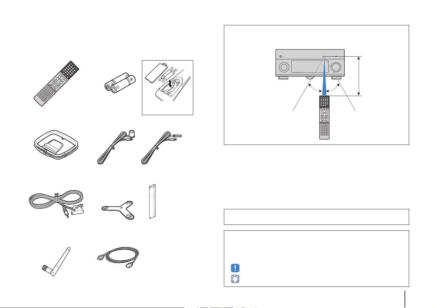
30° 30°
Within
6 m (20 ft)
Check that the following accessories are supplied with the product.
Remote control Batteries (AAA, R03, UM-4) (x2)
AM antenna FM antenna
*One of the above is supplied depending on the region of purchase.
Operating range of the remote control
• Point the remote control at the remote control sensor on the unit and remain within the operating range
shown below.
YPAO microphone Microphone base
Pole
(RX-A3040 only)
*Using for angle/height measurement during YPAO.
Wireless antenna Power cable
*The supplied power cable varies
depending on the region of purchase.
CD-ROM (Owner’s Manual)
Easy Setup Guide
Safety Brochure
• The illustrations of the main unit used in this manual are of the RX-A3040
(U.S.A. model), unless otherwise specified.
• Some features are not available in certain regions.
• Due to product improvements, specifications and appearance are subject to change without notice.
• This manual explains operations using the supplied remote control.
• This manual describes all the “iPod”, “iPhone” and “iPad” as the “iPod”. “iPod” refers to “iPod”, “iPhone”
and “iPad”, unless otherwise specified.
• indicates precautions for use of the unit and its feature limitations.
• indicates supplementary explanations for better use.
Accessories En 5
Page 6
FEATURES
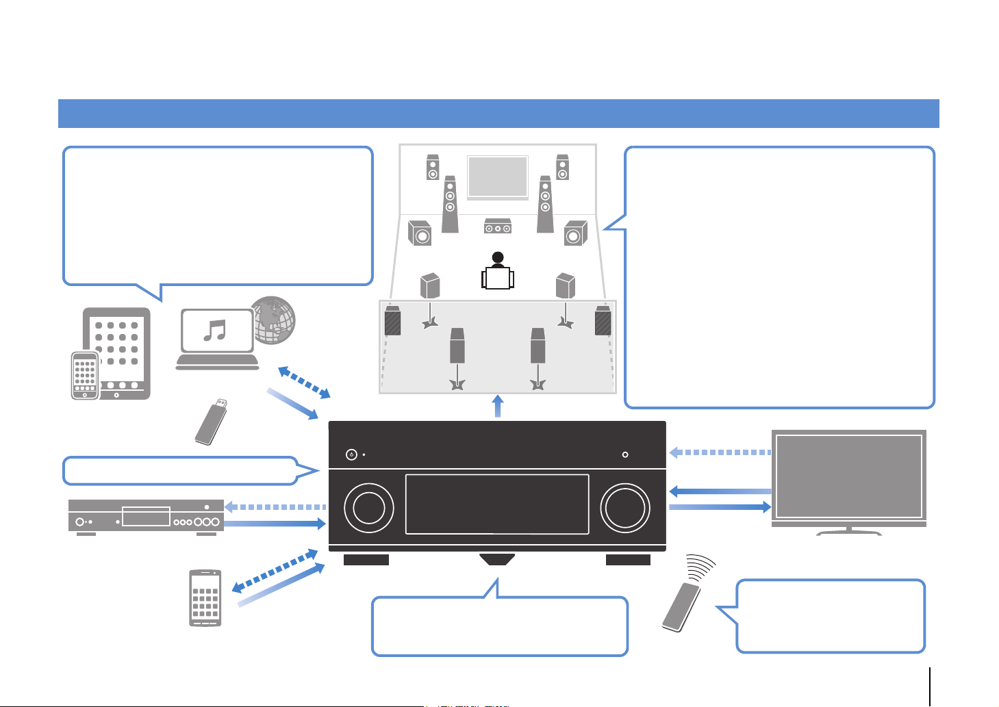
Speakers
BD/DVD player
HDMI Control
Audio/Video
TV remote control
Audio
HDMI Control
Audio
Audio/Video
TV
Sequential operation of a TV,
AV receiver, and BD/DVD
player (HDMI Control)
. p.168
Supports 2- to 9-channel (plus rear presence) speaker
system and up to 2 subwoofer connections. Allows
you to enjoy favorite acoustic spaces in various styles.
• Automatically optimizing the speaker
settings to suit your room (YPAO)
. p.47
• Reproducing stereo or multichannel
sounds with the sound fields like
actual movie theaters and concert halls
(CINEMA DSP)
. p.71
• Enjoying compressed music with
enhanced sound (Compressed Music
Enhancer)
. p.75
• Bi-amp connections, channel
expansion (with external power-amp)
and multi-zone configurations to
enhance your system
. p.24
iPod/iPhone/iPad
USB device
Network contents
Wide variety of supported content
• iPod/iPhone/iPad
. p.83
•USB
. p.86
• Media server (PC/NAS)
. p.89
• Internet radio
. p.92
•AirPlay
. p.95
3D and 4K Ultra HD signals supported
AV receiver (the unit)
Change the input source and favorite
settings with one touch (SCENE)
. p.68
Audio
Control
Audio/Video
(via HDMI/MHL)
Smartphone/Tablet
Control
What you can do with the unit
FEATURES ➤ What you can do with the unit En 6
Page 7
Full of useful functions!
HDMI Control
TV audio
Video from
external device
Wi-Fi or
Wireless Direct
Useful tips
❑ Connecting various devices (p.38)
A number of HDMI jacks and various input/output jacks
on the unit allow you to connect video devices (such as
BD/DVD players), audio devices (such as CD players),
game consoles, camcorders, and other devices.
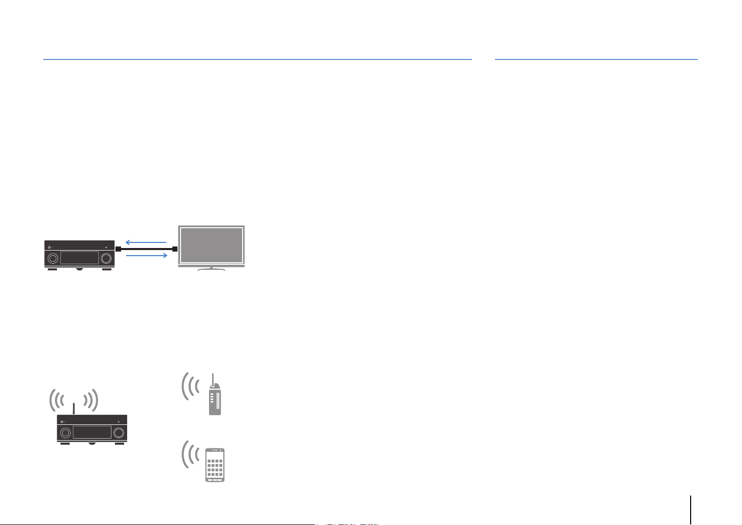
❑ Playing back TV audio in surround sound
with a single HDMI cable connection
(Audio Return Channel: ARC) (p.35)
When using an ARC-compatible TV, you only need one
HDMI cable to enable video output to the TV, audio
input from the TV, and the transmission of HDMI Control
signals.
❑ Various wireless connection methods
(p.59)
The unit supports the Wi-Fi feature that allows the unit to
connect to your wireless router (access point) without a
network cable connection. In addition, Wireless Direct
enables connecting a mobile device to the unit directly
without router.
❑ Surround playback with 5 speakers placed
in front (p.73)
If you have surround speakers but there is no space to
place them in the rear of your room, you can place them in
the front and enjoy multi-channel surround sound with the
5 speakers placed in the front (Virtual CINEMA FRONT).
❑ Operating external devices with the
supplied remote control (p.148)
You can operate external devices with the supplied
remote control by registering the remote control codes
of the external devices (such as a TV and BD/DVD
players).
❑ Low power consumption (p.141)
The ECO mode (power saving function) reduces the
unit’s power consumption.
❑ Easy operation and wireless music
playback from iPhone or Android™ device
By using the application for smartphone/tablet “AV
CONTROLLER”, you can control the unit from an
iPhone, iPad, iPod touch or Android devices. Visit the
Yamaha website for details.
I want to connect a playback device using HDMI for
video and non-HDMI for audio...
Use “Audio Select” in the “Option” menu to specify the
type of an audio input jack to be used for the
corresponding input source (p.110).
Video and audio are not synchronized...
Use “Lipsync” in the “Setup” menu to adjust the delay
between video and audio output (p.129).
I want to hear audio from the TV speakers...
Use “Audio Output” in the “Setup” menu to select the
output destination of signals input into the unit (p.133).
Your TV speakers may be selected as an output
destination.
I want to get more bass sounds…
Set “Extra Bass” in the “Option” menu to “On” to enjoy
enhanced bass sounds (p.109).
I want to change the on-screen menu language...
Use “Language” in the “Setup” menu to select a
language from English, Japanese, French, German,
Spanish, Russian, Italian and Chinese (p.46).
I want to update the firmware...
Use “FIRM UPDATE” in the “ADVANCED SETUP” menu
to update the unit’s firmware (p.147). If the unit is
connected to the Internet, a message will be displayed
on the TV when a firmware update is available (p.151).
Many other settings are available that let you to
customize the unit. For details, see the following pages.
• Input settings (p.112)
• SCENE settings (p.114)
• Sound program and surround decoder settings (p.117)
• Various function settings (p.121)
• Information view (such as audio signal and video
signal) (p.143)
• System settings (p.145)
FEATURES ➤ What you can do with the unit En 7
Page 8
CINEMA DSP
CINEMA DSP HD³
Level
CINEMA DSP 3D
Time
The excitement of a concert hall and the powerful sense of being inside a movie - we all want to enjoy these experiences in our own living room. Yamaha has pursued the fulfillment
of these desires for more than 20 years, and this fulfillment has now taken shape as the Yamaha AV receivers.
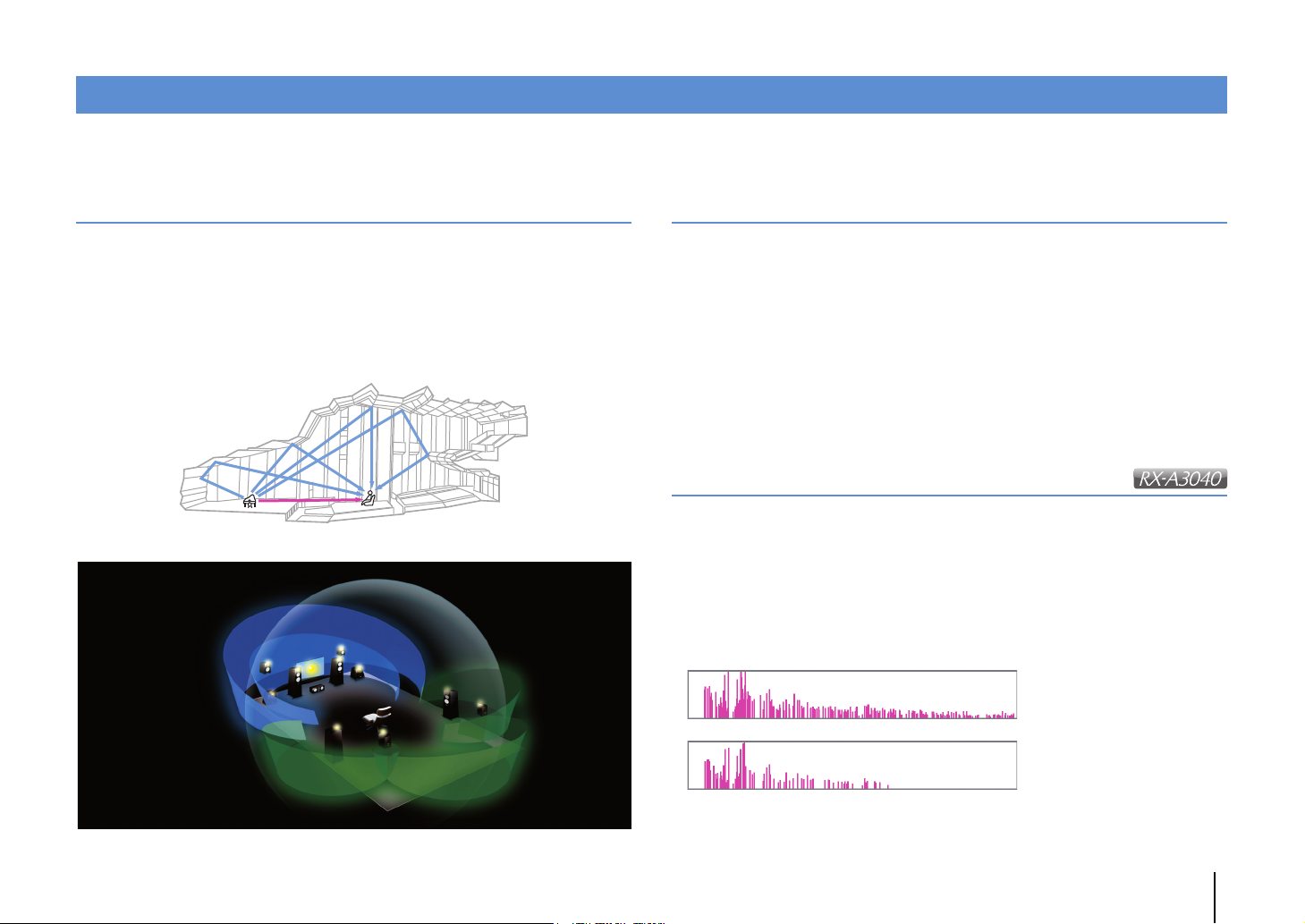
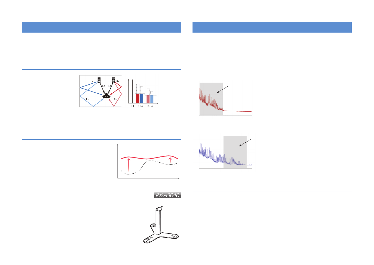
What is a sound field?
We perceive sound from a voice or an instrument not only as the sounds that are heard
directly but also as the “reflected” or “reverberant” sound that has been reflected by the
walls or ceiling of the building. The character of the reflected and reverberant sound is
affected by the shape, size, and material of the building, and all of these sounds taken
together are what give us the auditory sensation of being in that specific place.
This unique acoustical character of a specific space is what we call the “sound field”.
Conceptual diagram of a concert hall's sound field
Conceptual diagram of a sound field created by the unit
CINEMA DSP/CINEMA DSP 3D
Yamaha has accumulated a massive amount of acoustical data by analyzing the actual
sound fields of concert halls and performance spaces around the world. “CINEMA
DSP” allows this data to be applied to create sound fields. This unit contains a wide
variety of sound programs using CINEMA DSP.
By selecting a sound program that is appropriate to the content of the playback source
such as movies, music, or games, you can maximize the acoustical effectiveness of
that specific content. (For example, a sound program designed for movies can give you
the sensation of actually being in that scene.)
In addition, the “CINEMA DSP 3D” function uses 3-dimensional sound field data that
includes the axis of height, generating an even more realistic sound field with a spatial
sense.
CINEMA DSP HD
“CINEMA DSP HD³” is Yamaha's flagship 3D sound field playback technology that
takes full advantage of the massive amount of acoustic reflection data included in the
sound field data. With support for rear presence speaker output, it delivers more than
twice as much capability for generating acoustic reflections as conventional CINEMA
DSP 3D, in addition to high-frequency playback capability, delivering an utterly natural
and powerful spatial sound field.
Capability for reproducing reflections
(when the sound program “Hall in Munich” is selected)
FEATURES ➤ What you can do with the unit En 8
Page 9
YPAO
Compensation
Time
Level
YPAO Volume OFF
YPAO Volume ON
FrequencyLow High
Level
High
Frequency
Loudness
Playback bandwidth of a 44.1/48 kHz
signal (such as a CD)
Frequency
Loudness
Playback bandwidth of a
88.2/96 kHz signal
YPAO is Yamaha original automatic calibration system to optimizing your sound and
surround environment by using microphone measurement. It can be create ideal
listening environment for maximizing high sound quality contents playback by adjusting
various speakers setting and the sound field automatically.
YPAO-R.S.C.
In typical home, the sound
has problems such as a
blurred low-frequency range
or a smearing of the
acoustical sound image
caused by undesirable
sound reflection from the
walls or ceiling.
"YPAO-R.S.C." is technology that reduces only the unwanted reflections and produces
the acoustic perfection for your listening environment.
YPAO Volume
YPAO Volume automatically adjusts the high
and low frequency levels at any volume level so
that you hear natural sounds even at low
volume.
Unrivaled audio and video quality
High-resolution music enhancer
Hi-bit high-sampling extension up to 96 kHz / 24-bit can be applied to lossless 44.1/48
kHz content such as from a CD (2-channel PCM) or a FLAC file for further heightening
of the musicality in the original content (p.109)
Before processing
After processing
YPAO 3D measurement
The direction (angle) of front, surround and presence speakers,
and the height of presence speakers as seen from the listening
position is measured, and compensation is applied to maximize
the 3D sound field effectiveness of the CINEMA DSP.
High-quality video processing
From low-quality digital video to BD (Blu-ray disc) images, any content can be played
back as a high-quality image (p.131).
• Motion adaptive and edge adaptive deinterlacing
• Multi-cadence (including 3-2 pull-down) detection
• Up to 6 presets that can be applied separately to each input source
You can also apply fine touches such as detail enhancement and edge enhancement.
FEATURES ➤ What you can do with the unit En 9
Page 10
Expandable to meet diverse needs
External power amp
Living room (main zone)
Study room
(such as Zone2)
Living room (main zone)
Kitchen
(such as Zone4)
Support for bi-amp connections and external power amp
expansion
To obtain even high audio quality, you can connect front speakers that support power
amp expansion, or expand your system by adding an external power amp (such as a
Hi-Fi amp).
For details, refer to “Advanced speaker configuration” (p.24).
The best expandability in Yamaha
By connecting an external power amp, you can
enjoy the highest peak of CINEMA DSP
- an 11.2-channel 3-dimensional sound field.
(Example)
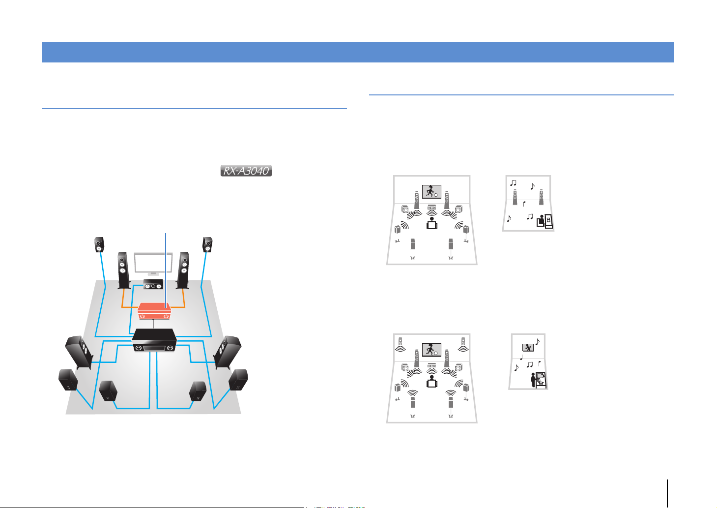
Multi-zone function
The multi-zone function (
where the unit is installed (main zone) and in other rooms (such as Zone2).
(The following shows examples of use.)
Enjoying music using speakers in another room
While enjoying multi-channel playback in your living room, you can listen to music
through the speakers of a different room.
Enjoying videos using a TV in another room
(HDMI connection)
While enjoying multi-channel playback in your living room, you can enjoy videos and
music being input via HDMI on a TV in a different room.
p.97
) allows you to play back different input sources in the room
FEATURES ➤ What you can do with the unit En 10
Page 11
Part names and functions
4 5231
6
8
7
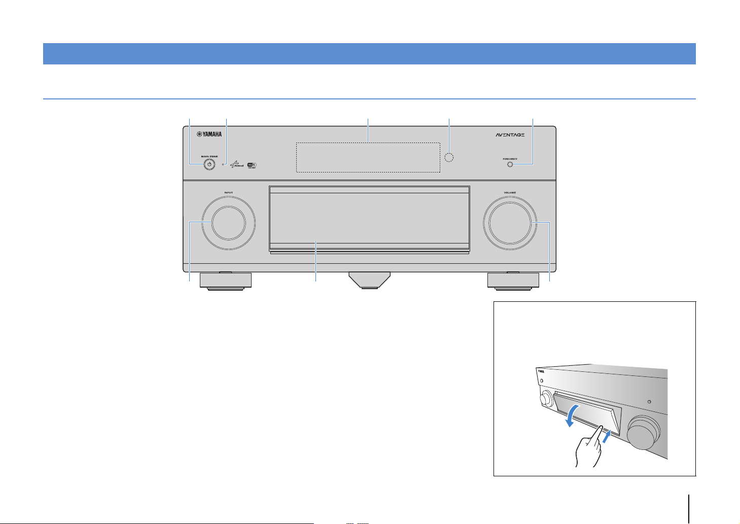
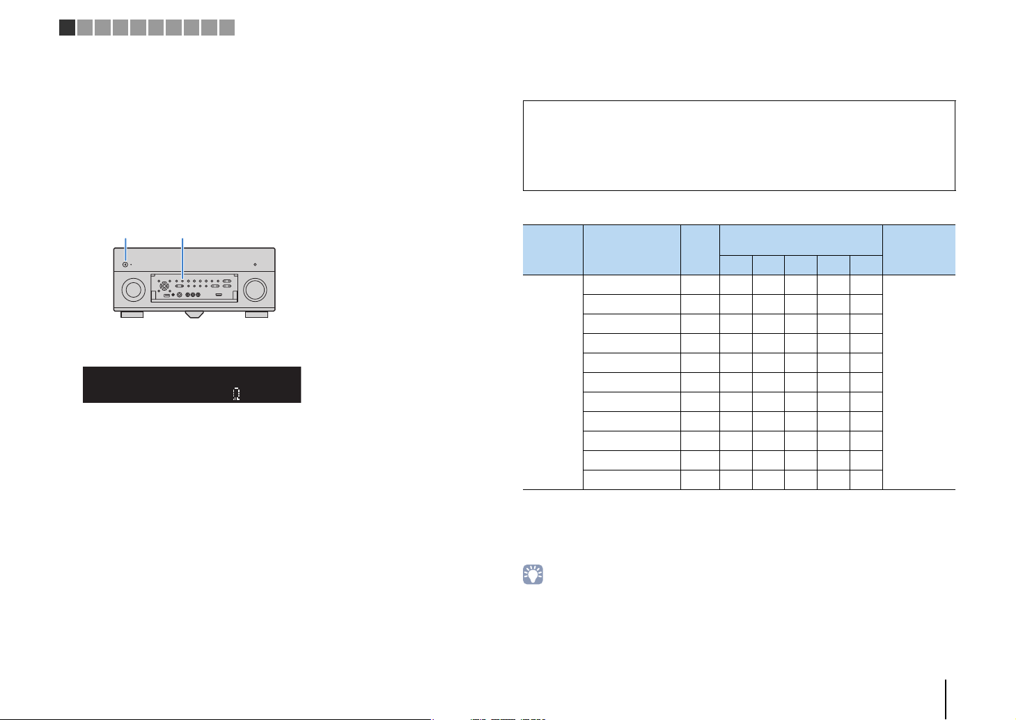
Front panel
1 MAIN ZONE z key
Turns on/off (standby) the unit.
2 Standby indicator
Lights up when the unit is in standby mode under any of the
following conditions.
• HDMI Control is enabled (p.132)
• Standby Through is enabled (p.133)
• Network Standby is enabled (p.134)
• An iPod is being charged (p.83)
3 Front display
Displays information (p.13).
4 Remote control sensor
Receives remote control signals (p.5).
5 PURE DIRECT key
Enables/disables Pure Direct (p.75).
6 INPUT knob
Selects an input source.
7 Front panel door
For protecting controls and jacks (p.12).
8 VOLUME knob
Adjusts the volume.
Opening the front panel door
• To use controls or jacks behind the front panel door, gently
press the bottom of the door to open it. Keep the door closed
when not using controls or jacks behind the front panel door.
(Be careful not to trap your fingers.)
FEATURES ➤ Part names and functions En 11
Page 12
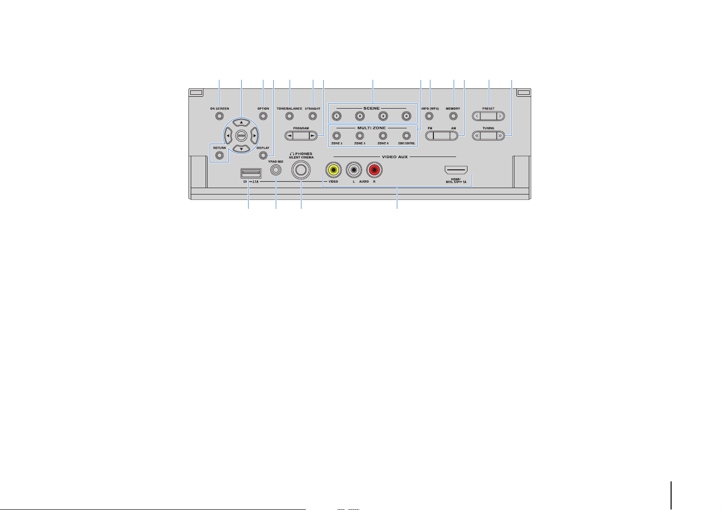
■ Inside of the front panel door
BE JL9ACD HIK0FG
MNO P
9 ON SCREEN key
Displays the on-screen menu on the TV.
0 Menu operations keys
Cursor keys Select a menu or a parameter.
ENTER Confirms a selected item.
RETURN Returns to the previous screen.
A OPTION key
Displays the option menu (p.107).
B DISPLAY key
Displays status information on the TV (p.106).
C TONE/BALANCE key
Adjusts the high-frequency range and low-frequency range
of output sounds (p.108).
Adjusts the left/right channel volume balance for Zone2 or
Zone3 (p.102).
D STRAIGHT key
Enables/disables the straight decode mode (p.74).
E PROGRAM keys
Select a sound program or a surround decoder (p.70).
F SCENE keys
Select the registered input source, sound program, and
various settings with one touch. Also, turns on the unit when
it is in standby mode (p.68).
G MULTI ZONE keys
ZONE 2–4 Enables/disables the audio output to
ZONE CONTROL Changes the zone that is controlled by
each zone (p.101).
the keys and knobs on the front panel
(p.101).
H INFO (WPS) key
Selects the information displayed on the front display
(p.106).
Enters the wireless network connection setup (WPS push
button configuration) by holding down for 3 seconds (p.61).
I MEMORY key
Registers FM/AM radio stations as preset stations (p.77).
J FM and AM keys
Switch between FM and AM (p.76).
K PRESET keys
Select a preset FM/AM radio station (p.77).
L TUNING keys
Select the radio frequency (p.76).
M USB jack
For connecting a USB storage device (p.86) or an iPod
(p.83).
N YPAO MIC jack
For connecting the supplied YPAO microphone (p.47).
O PHONES jack
For connecting headphones.
P VIDEO AUX jacks
For connecting a device, such as a camcorder and a game
console (p.40, 41) or a smartphone (p.41).
FEATURES ➤ Part names and functions En 12
Page 13
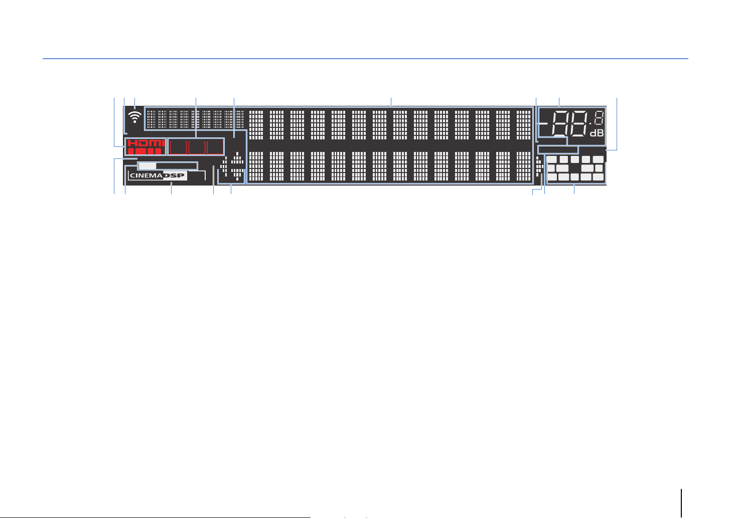
Front display (indicators)
OUT 21 3
IN
VOLUME
MUTE
ADAPTIVE DRC VIRTUAL
3
ZONE
ECO
2
SBLRPL SBRSB RPR
SW1
SL SW2 SR
FPL
CL R
FPR
ENHANCER
PA RT Y
STEREO TUNED
HD
SLEEP
ZONE3ZONE
4
HD
32
98
7
B
@ DF
1
6
C
4 5
AD E
(RX-A3040 U.S.A. model)
1 HDMI
Lights up when HDMI signals are being input or output.
IN
Lights up when HDMI signals are being input.
OUT1/OUT2
Indicates the HDMI OUT jacks currently outputting an HDMI
signal.
2 ECO
Lights up when the unit is in the eco mode (p.141).
3 Signal strength indicator
Indicates the strength of the wireless network signal (p.59).
4 ZONE indicators
Lights up when Zone2, Zone3 or Zone4 is enabled (p.101).
5 SLEEP
Lights up when the sleep timer is on.
6 Information display
7 MUTE
8 Volume indicator
Displays the current status (such as input name and sound
mode name). You can switch the information by pressing
INFO (p.106).
Blinks when audio is muted.
Indicates the current volume.
9 VIRTUAL
Lights up when the Virtual Presence Speaker (VPS) (p.71) or
the virtual surround processing (p.73) is working.
0 ENHANCER
Lights up when Compressed Music Enhancer (p.75) is
working.
A STEREO
Lights up when the unit is receiving a stereo FM radio signal.
TUNED
Lights up when the unit is receiving an FM/AM radio station
signal.
HD
(U.S.A. model only)
Lights up when the unit is receiving an HD Radio station
signal.
B CINEMA DSP indicator
(RX-A3040)
“CINEMA DSP HD” lights up when CINEMA DSP (p.71) is
working. “CINEMA DSP !” lights up when CINEMA DSP
HD³ is activated.
(RX-A2040)
“CINEMA DSP” lights up when CINEMA DSP (p.71) is
working. “CINEMA DSP n” lights up when CINEMA DSP 3D
is activated.
C PA RT Y
D Cursor indicators
E ADAPTIVE DRC
F Speaker indicators
Lights up when the unit is in the party mode. (p.102)
Indicate the remote control cursor keys currently operational.
Lights up when Adaptive DRC (p.108) is working.
Indicate speaker terminals from which signals are output.
A Front speaker (L)
S Front speaker (R)
D Center speaker
F Surround speaker (L)
G Surround speaker (R)
H Surround back speaker (L)
J Surround back speaker (R)
K Surround back speaker
B Front presence speaker (L)
N Front presence speaker (R)
M Rear presence speaker (L)
< Rear presence speaker (R)
C Subwoofer (1)
V Subwoofer (2)
FEATURES ➤ Part names and functions En 13
Page 14
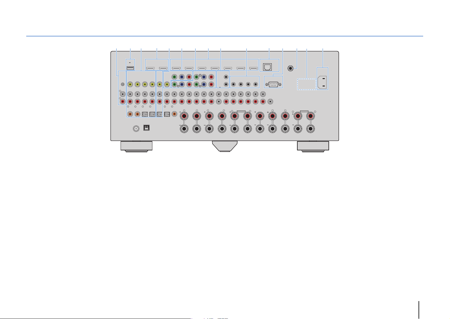
Rear panel
* The area around the video/audio output
jacks is marked in white on the actual
product to prevent improper connections.
(RX-A3040 U.S.A. model)
21 4 A6 E@ B C7 983
DC OUT
5V
0.5A
PHONO
(1 BD/DVD)
GND
L
R
1
COAXIAL
75Ω
1 PHONO jacks
For connecting to a turntable (p.39).
2 DC OUT jack
For connecting to an optional accessory.
3 AV 1–4 jacks
For connecting to video/audio playback devices and
inputting video/audio signals (p.38).
4 HDMI OUT 1 jack
For connecting to an HDMI-compatible TV and outputting
video/audio signals (p.35). When using ARC, TV audio signal
can also be input through the HDMI OUT 1 jack.
HDMI OUT 2 (ZONE OUT) jack
For connecting to an HDMI-compatible TV and outputting
video/audio signals (p.37), or for connecting to an
HDMI-compatible device used in Zone2 or Zone4 (p.99).
5
HDMI OUT
AV 1 AV 2 AV 3 AV 4 AV 5 AV 6 AV 7
12
(1 BD/DVD)
ARC
(ZONE OUT)
AV 3 AV 4AV 2AV 1
3
2
OPTICAL
COAXIAL
ANTENNA
HD Radio
AM
FM
4
(4 RADIO)
OPTICAL
MONITOR OUT/
AV OUT
Y
P
BPR
ZONE OUT
A
Y
AV 1
AUDIO 3AUDIO 2AUDIO 1
(2 TV)
5
OPTICAL
AUDIO 4
6
COAXIAL
R
HDMI
COMPONENT VIDEO
AV 2
YP
B
C
PRPBYP
AV 3
MULTI CH INPUT
FRONT
SURROUND SUR. BACK
L R
TRIGGER
OUT
RPB
1
2
12V 0.1A
MAX. TOTAL
RPB
CENTER
ZONE OUT/PRE OUT
ZONE 2
/
SUBWOOFER
F. PRE SENCE
SINGLE
REMOTE
11
IN
OUT IN OUT
/
ZONE 3
FRONT
R. PRESENCE
SPEAKERS
ZONE 2/ZONE 3/R.PRESENCE
R
EXTRA SP2
5 AV OUT jacks
For outputting video/audio to a recording device (such as a
VCR) (p.44).
6 MONITOR OUT/ZONE OUT
(component/composite video) jacks
For connecting to a TV that supports component or
composite video and outputting video signals (p.36) or for
connecting to a zone video monitor used in Zone2 or Zone3
(p.99).
7 COMPONENT VIDEO (AV 1–3) jacks
For connecting to video playback devices that support
component video and inputting video signals (p.38).
8 HDMI (AV 1–7) jacks
For connecting to HDMI-compatible playback devices and
inputting video/audio signals (p.38).
9 TRIGGER OUT 1–2 jacks
For connecting to devices that support the trigger function
(p.45).
PRE OUT
SURROUND SUR. BACK
L
(SINGLE) (FRONT)
SUBWOOFER
CENTER FRONTSURROUND BACKSURROUND
(
REAR
NETWORK
1
2
)
CENTER
RS-232C
)
(3 NET
RL
L
D
WIRELESS
AC IN
ZONE 2/ZONE 3/F.PRESENCE/
BI–AMP
EXTRA SP1
R
L
0 REMOTE IN/OUT 1–2 jacks
For connecting to an infrared signal receiver/emitter that
allows you to operate the unit and other devices from another
room (p.100).
A NETWORK jack
For connecting to a network with a network cable (p.43).
B RS-232C terminal
This is a control expansion terminal for custom installation.
Consult your dealer for details.
C WIRELESS jack
For connecting the supplied wireless antenna (p.43).
D VOLTAGE SELECTOR
(General model only)
Selects the switch position according to your local voltage
(p.45).
E AC IN jack
For connecting the supplied power cable (p.45).
FEATURES ➤ Part names and functions En 14
Page 15
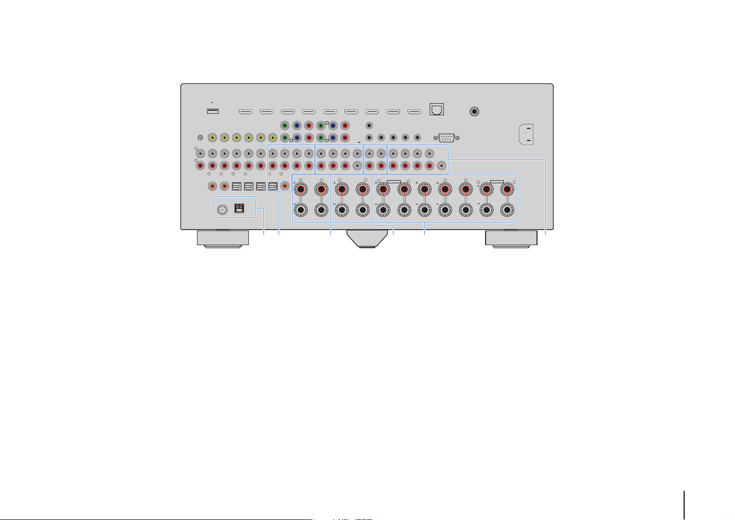
PHONO
* The area around the video/audio output
jacks is marked in white on the actual
product to prevent improper connections.
(RX-A3040 U.S.A. model)
L
R
DC OUT
5V
0.5A
(1 BD/DVD)
GND
1
COAXIAL
75Ω
HDMI OUT
AV 1 AV 2 AV 3 AV 4 AV 5 AV 6 AV 7
12
(1 BD/DVD)
ARC
(ZONE OUT)
AV 3 AV 4AV 2AV 1
AV OUT
MONITOR OUT/
Y
P
BPR
ZONE OUT
A
Y
AV 1
AUDIO 3AUDIO 2AUDIO 1
(2 TV)
4
3
2
OPTICAL
OPTICAL
COAXIAL
ANTENNA
HD Radio
AM
FM
(4 RADIO)
5
OPTICAL
AUDIO 4
6
COAXIAL
R
HDMI
COMPONENT VIDEO
AV 2
YP
B
C
PRPBYP
AV 3
MULTI CH INPUT
FRONT
SURROUND SUR. BACK
L R
TRIGGER
OUT
RPB
1
2
12V 0.1A
MAX. TOTAL
RPB
CENTER
ZONE OUT/PRE OUT
ZONE 2
/
SUBWOOFER
F. PRE SENCE
SINGLE
REMOTE
11
IN
OUT IN OUT
PRE OUT
/
ZONE 3
FRONT
SURROUND SUR. BACK
R. PRESENCE
SPEAKERS
ZONE 2/ZONE 3/R.PRESENCE
R
EXTRA SP2
L
(SINGLE) (FRONT)
SUBWOOFER
CENTER FRONTSURROUND BACKSURROUND
(
REAR
NETWORK
1
2
)
CENTER
RS-232C
WIRELESS
)
(3 NET
ZONE 2/ZONE 3/F.PRESENCE/
RL
BI–AMP
L
EXTRA SP1
R
AC IN
L
JGF I KH
F ANTENNA jacks
For connecting to FM and AM antennas (p.42).
G AUDIO 1–4 jacks
For connecting to audio playback devices and inputting
audio signals (p.39).
H MULTI CH INPUT jacks
For connecting to a device that supports multi-channel
output and inputting audio signals (p.44).
I ZONE OUT/PRE OUT jacks (RX-A3040)
For connecting to an external amplifier used in Zone2 or
Zone3 and outputting audio (p.98), or for connecting to an
external power amplifier for front presence or rear presence
channels (p.33).
ZONE OUT jacks (RX-A2040)
For connecting to an external amplifier used in Zone2 or
Zone3 and outputting audio (p.98).
J SPEAKERS terminals
For connecting to speakers (p.18).
K PRE OUT jacks
For connecting to a subwoofer with built-in amplifier (p.22) or
to an external power amplifier (p.33).
FEATURES ➤ Part names and functions En 15
Page 16
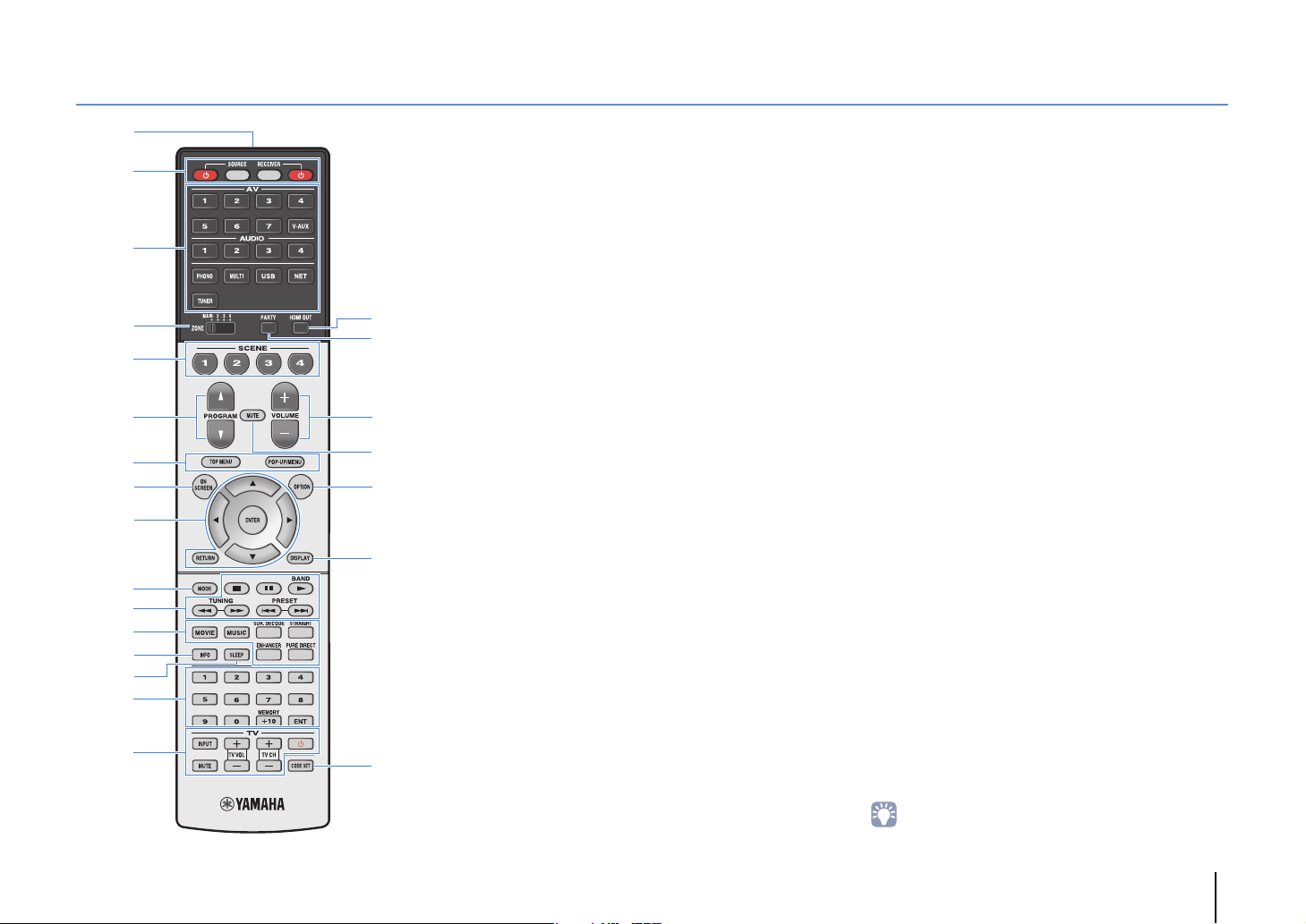
Remote control
H
J
G
K
L
M
1
3
2
5
4
6
I
7
E
D
F
8
A
B
:
C
9
1 Remote control signal transmitter
Transmits infrared signals.
2 SOURCE z key
Turns on/off an external device.
SOURCE key
Sets the remote control to operate external devices (p.149).
This key lights up in green after pressed.
RECEIVER key
Sets the remote control to operate the unit (p.149). This key
lights up in orange after pressed.
RECEIVER z key
Turns on/off (standby) the unit.
3 Input selection keys
Select an input source for playback.
AV 1 – 7 AV 1–7 jacks
V-A UX VIDEO AUX jacks (on the front panel)
AUDIO 1–4 AUDIO 1–4 jacks
PHONO PHONO jacks
MULTI MULTI CH INPUT jacks
USB USB jack (on the front panel)
NET NETWORK sources (press repeatedly to select
TUNER FM/AM radio
a desired network source)
4 ZONE switch
Changes the zone that is controlled by the remote control
(p.101).
5 SCENE keys
Select the registered input source, sound program, and
various settings with one touch. Also, turns on the unit when
it is in standby mode (p.68).
6 PROGRAM keys
Select a sound program (p.70).
7 External device operation keys
Select menus for external devices (p.149).
8 ON SCREEN key
Displays the on-screen menu on the TV.
9 Menu operation keys
Cursor keys Select a menu or a parameter.
ENTER Confirms a selected item.
RETURN Returns to the previous screen.
0 MODE key
Switches the iPod operation modes (p.85).
(U.S.A. model only) Selects an HD Radio audio program
(p.78).
A Radio keys
Operate the FM/AM radio when “TUNER” is selected as the
input source (p.76).
BAND Switches between FM and AM radio.
PRESET Select a preset station.
TUNING Select the radio frequency.
External device operation keys
Let you play back and perform other operations for external
devices when an input source other than “TUNER” is
selected (p.149).
B Sound mode keys
Select a sound mode (p.70).
C INFO key
Selects the information displayed on the front display (p.106).
D SLEEP key
Switches the unit to standby mode automatically after a
specified period of time has elapsed (sleep timer). Press
repeatedly to set the time (120 min, 90 min, 60 min, 30 min, off).
E Numeric keys
Let you enter numerical values, such as radio frequencies.
MEMORY key
Registers FM/AM radio stations as presets (p.77).
F TV operation keys
Let you select TV input and volume, and perform other TV
operations (p.148).
G HDMI OUT key
Selects HDMI OUT jacks to be used for video/audio output
(p.67).
H PA RTY k e y
Turns on/off the party mode (p.102).
I VOLUME keys
Adjust the volume.
J MUTE key
Mutes the audio output.
K OPTION key
Displays the option menu (p.107).
L DISPLAY key
Displays status information on the TV (p.106).
M CODE SET key
Registers remote control codes of external devices on the
remote control (p.148).
• To operate external devices with the remote control, register a
remote control code for each device before using (p.148).
FEATURES ➤ Part names and functions En 16
Page 17

PREPARATIONS
General setup procedure
1 Connecting speakers (p.18)
2 Connecting a TV (p.35)
3 Connecting playback devices (p.38)
4 Connecting the FM/AM antennas (p.42)
Connecting a network cable or the
5
wireless antenna (p.43)
6 Connecting other devices (p.44)
7 Connecting the power cable (p.45)
Selecting an on-screen menu language
8
(p.46)
Basic speaker configuration (p.19)
Select the speaker layout and connect the speakers to the unit.
Advanced speaker configuration (p.24)
Apply bi-amp connections, channel expansion (using an external power amplifier) or multi-zone
configurations to enhance the system.
Connect a TV to the unit.
Connect video devices (such as BD/DVD players) and audio devices (such as CD players) to the unit.
Connect the supplied FM/AM antennas to the unit.
Connect the unit to a router (access point) with a network cable, or connect the supplied wireless antenna
for establishing a wireless network connection.
Connect external devices such as recording devices.
After all the connections are complete, plug in the power cable.
Select the desired on-screen menu language.
Optimizing the speaker settings
9
automatically (YPAO) (p.47)
Connecting to a network device wirelessly
10
(p.59)
This completes all the preparations. Enjoy playing movies, music, radio and other content with the unit!
Optimize the speaker settings, such as volume balance and acoustic parameters, to suit your room
(YPAO).
Connect the unit to a wireless router (access point) or a mobile device by establishing a wireless
connection.
PREPARATIONS ➤ General setup procedure En 17
Page 18
0.3 m (1 ft) or more
1.8 m
(5.9 ft)
0.5 to 1 m
(1.6 to 3.3 ft)
1.8 m
(5.9 ft)
0.5 to 1 m
(1.6 to 3.3 ft)
10°~30°10°~30°
1.8 m
(5.9 ft)
1.8 m
(5.9 ft)
1 2 3 4 5 6 7 8 9 10
1 Connecting speakers
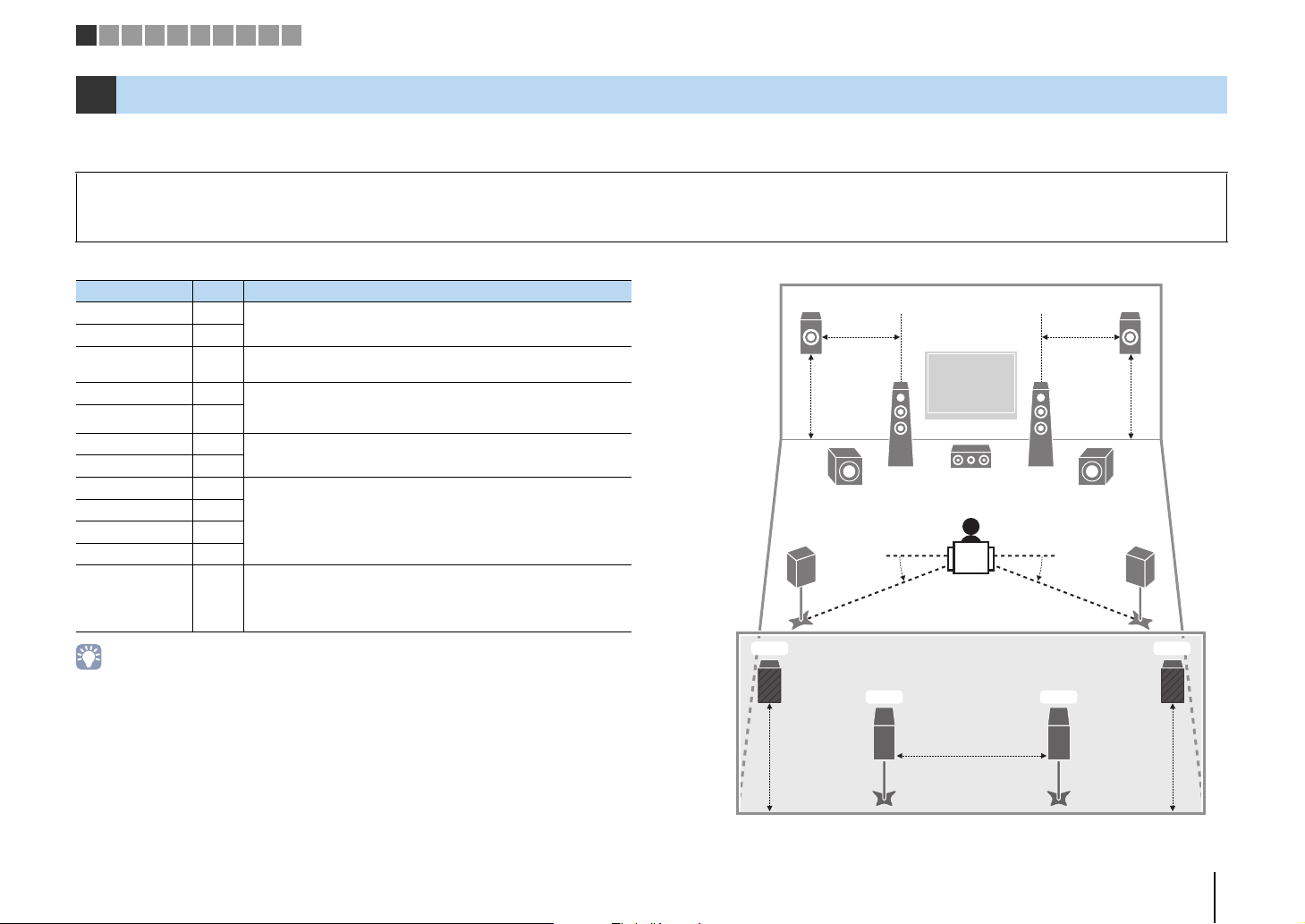
The unit has 9 built-in amplifiers. You can connect 2 to 11 speakers and up to 2 subwoofers to create the favorite acoustic space in your room.
You can also apply bi-amp connections, channel expansion (using an external power amplifier) or multi-zone configurations to enhance your system (p.24).
Caution
• Under its default settings, the unit is configured for 8-ohm speakers. When connecting 6-ohm speakers, set the unit’s speaker impedance to “6 MIN”. In this case, you can also use 4-ohm speakers as the front speakers.
For details, see “Setting the speaker impedance” (p.22).
Functions of each speaker
Speaker type Abbr. Function
Front (L) 1
Front (R) 2
Center 3
Surround (L) 4 Produce surround left/right channel sounds. Surround speakers
Surround (R) 5
Surround back (L) 6
Surround back (R) 7
Front presence (L) E
Front presence (R) R
Rear presence (L) T
Rear presence (R) Y
Subwoofer 9
• Use “Ideal speaker layout” (diagram on the right) as reference. You do not need to exactly adjust the
speaker layout to this diagram since the YPAO function of the unit will automatically optimize the speaker
settings (such as distances) to suit the speaker layout.
• When using only one surround back speaker, place it straight behind the listening position (middle of “SBL”
and “SBR” in the diagram).
• The unit creates front Virtual Presence Speaker (VPS) using the front, center, and surround speakers to
produce 3-dimensional sound fields even when no front presence speakers are connected. However, we
recommend using front presence speakers in order to experience the full effect of the sound fields (and
rear presence speakers for further spatial sounds).
• (RX-A3040 only)
The unit creates rear Virtual Presence Speaker (VPS) using the front, center, and surround speakers to
produce natural 3-dimensional sound fields when front presence speakers are connected but no rear
presence speakers.
Produce front left/right channel sounds (stereo sounds).
Produces center channel sounds (such as movie dialogues and
vocals).
also produce surround back channel sounds when no surround
back speakers are connected.
Produce surround back left/right channel sounds.
Produce CINEMA DSP effect sounds. In combination with CINEMA
DSP HD³ (RX-A3040) or CINEMA DSP 3D (RX-A2040) (p.71), the
presence speakers create a natural 3-dimensional sound field in
your room.
Produces LFE (low-frequency effect) channel sounds and
reinforces bass parts of other channels.
This channel is counted as “0.1”. You can connect 2 subwoofers to the
unit and place them on the left/right (or front/rear) sides of the room.
Ideal speaker layout
E
4
T Y
R
12
39
9
5
6
7
PREPARATIONS ➤ Connecting speakers En 18
Page 19
1 2 3 4 5 6 7 8 9 10
Basic speaker configuration
■ Placing speakers in your room
Depending on the number of speakers, place the speakers and subwoofer in your room. This section describes the representative speaker layout examples.
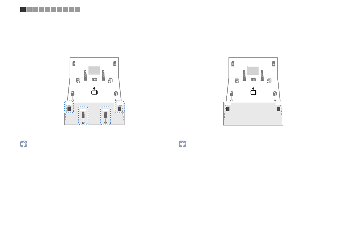
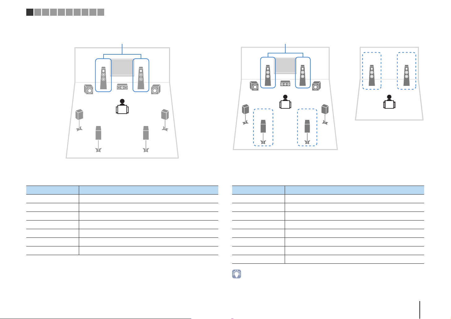
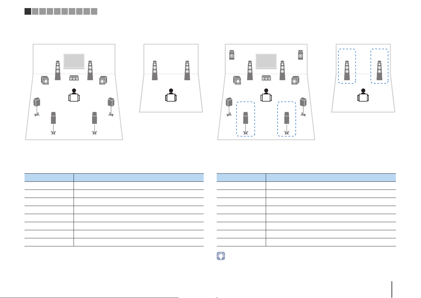
❑ 9.2+2-channel system
(using both surround back and rear presence speakers)
E
12
9
45
T Y
39
6 7
R
This speaker system brings out the full performance of the unit and allows you to enjoy
a highly-natural 3-dimensional sound field with any contents.
• The surround back speakers and rear presence speakers do not produce sounds simultaneously. The unit
automatically changes the speakers to be used, depending on the selected sound program (p.71).
• When using front presence and rear presence speakers installed to the ceiling, set “Layout (Front
Presence/Rear Presence)” (p.127) in the “Setup” menu to “Overhead” after connecting the power cable to
an AC wall outlet.
• (RX-A3040 only)
You can make an 11-channel system by using an external power amplifier (p.25).
❑ 9.2-channel system (using rear presence speakers)
E
12
9
45
T Y
39
This speaker system uses the front and rear presence speakers to produce a
highly-natural 3-dimensional sound field, and is suited for enjoying 5.1-channel contents.
• When using front presence and rear presence speakers installed to the ceiling, set “Layout (Front
Presence/Rear Presence)” (p.127) in the “Setup” menu to “Overhead” after connecting the power cable to
an AC wall outlet.
R
PREPARATIONS ➤ Connecting speakers En 19
Page 20
21
39
45
9
67
ER
1 2 3 4 5 6 7 8 9 10
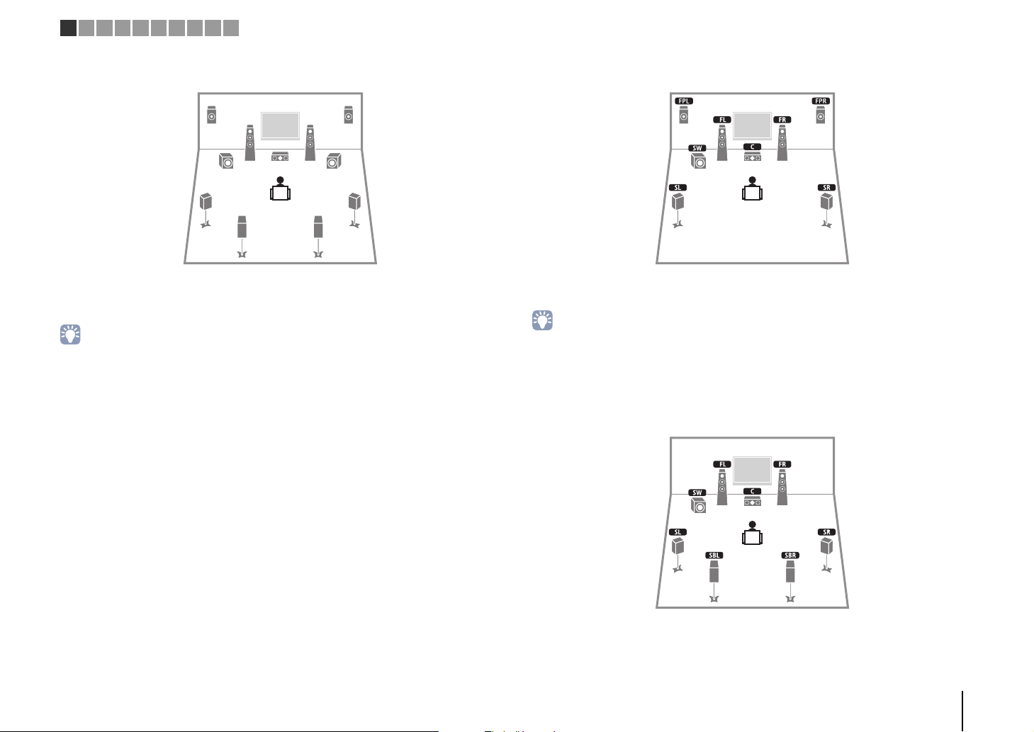
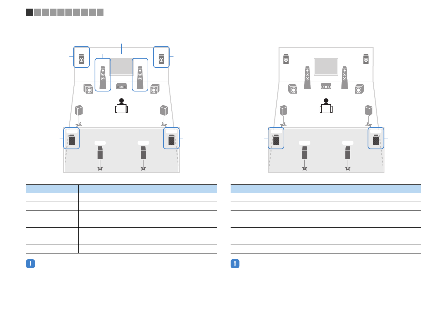
❑ 9.2-channel system (using surround back speakers)
This speaker system uses the front presence speakers to produce a natural
3-dimensional sound field, and also allows you to enjoy extended surround sounds
using the surround back speakers.
• When using front presence speakers installed to the ceiling, set “Layout (Front Presence)” (p.127) in the
“Setup” menu to “Overhead” after connecting the power cable to an AC wall outlet.
• (RX-A3040 only)
This speaker system creates rear Virtual Presence Speaker (VPS) using the front, center and surround
speakers to produce a natural 3-dimensional sound field.
❑ 7.1-channel system (using front presence speakers)
This speaker system uses the front presence speakers to produce a natural
3-dimensional sound field, and is suited for enjoying 5.1-channel contents.
• When using front presence speakers installed to the ceiling, set “Layout (Front Presence)” (p.127) in the
“Setup” menu to “Overhead” after connecting the power cable to an AC wall outlet.
• (RX-A3040 only)
This speaker system creates rear Virtual Presence Speaker (VPS) using the front, center and surround
speakers to produce a natural 3-dimensional sound field.
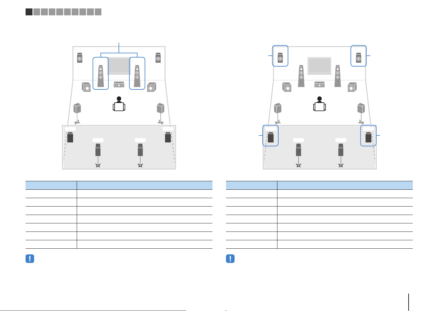
❑ 7.1-channel system (using surround back speakers)
This speaker system creates front Virtual Presence Speaker (VPS) using the front,
center and surround speakers to produce a 3-dimensional sound field, and also allows
you to enjoy extended surround sounds using the surround back speakers.
PREPARATIONS ➤ Connecting speakers En 20
Page 21
1 2 3 4 5 6 7 8 9 10
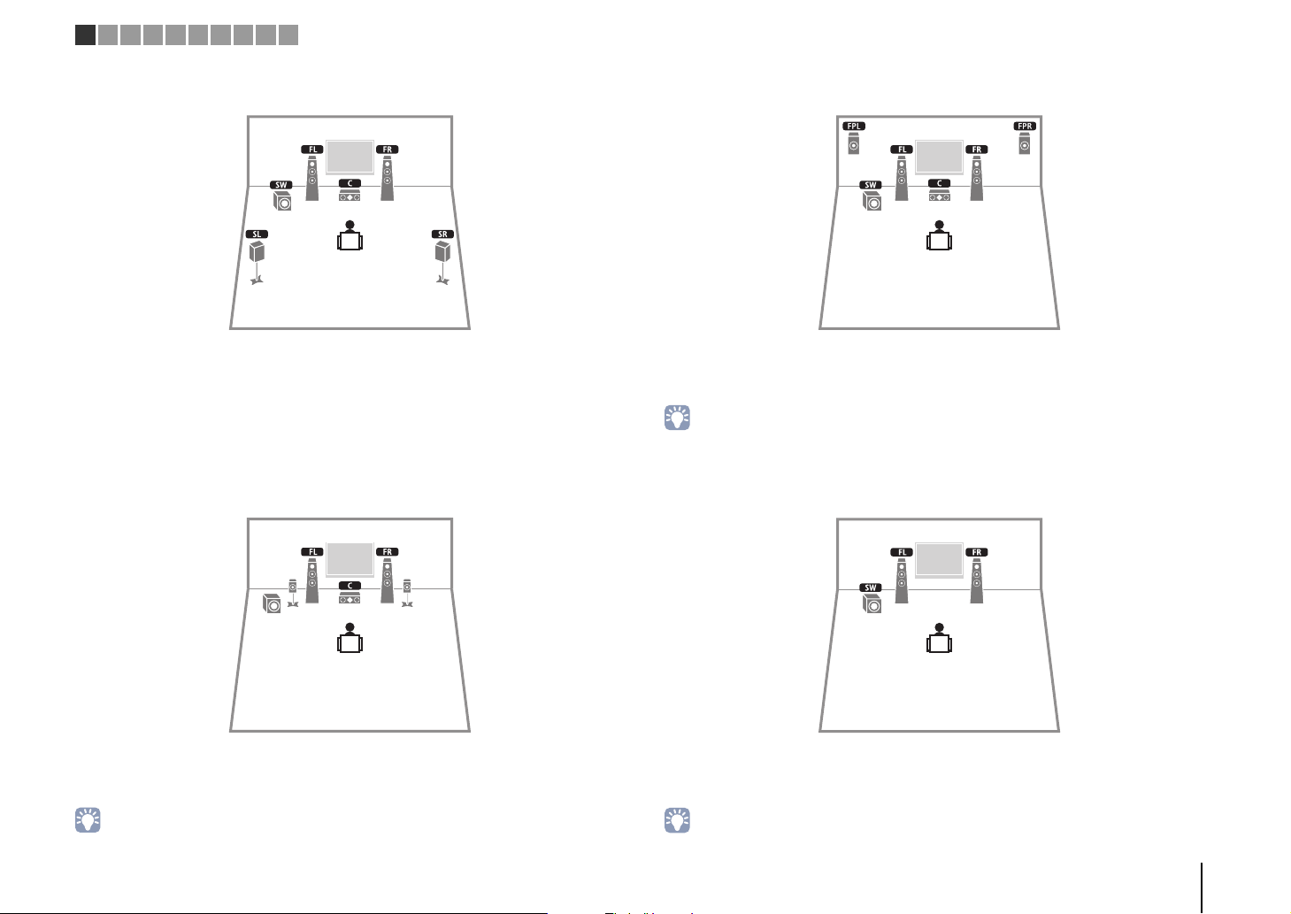
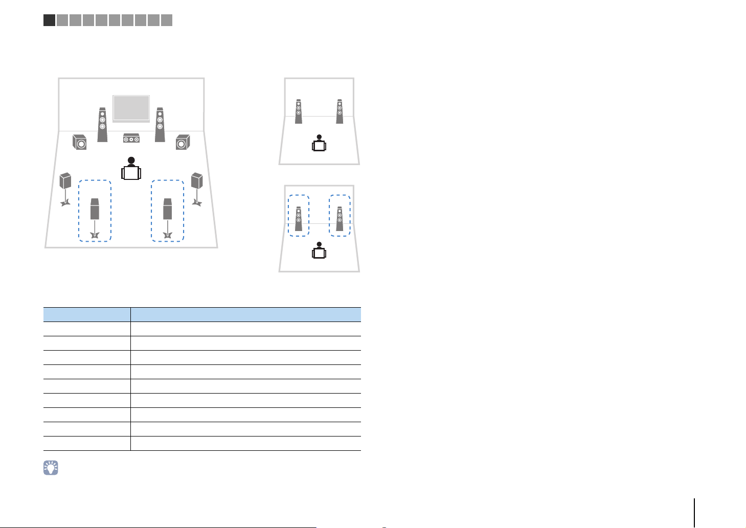
❑ 5.1-channel system
This speaker system creates front Virtual Presence Speaker (VPS) using the front,
center and surround speakers to produce a 3-dimensional sound field, and is suited for
enjoying 5.1-channel contents.
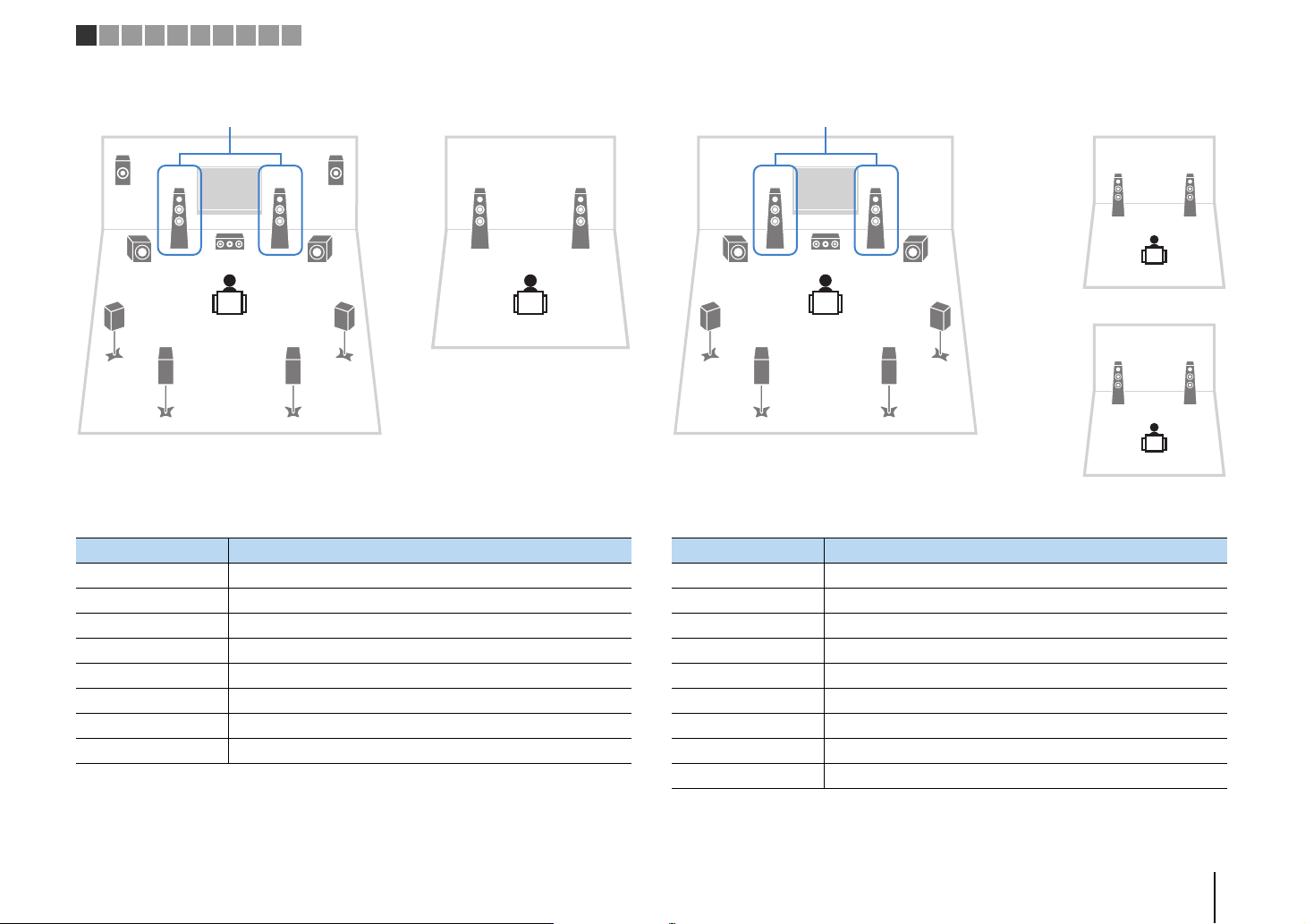
❑ Front 5.1-channel system (using surround speakers)
45
9
❑ Front 5.1-channel system (using front presence speakers)
This speaker system uses the front presence speakers to produce a natural
3-dimensional sound field, and creates the virtual surround speakers using the front
speakers to allow you to enjoy multi-channel surround sound (Virtual CINEMA DSP).
• When using front presence speakers installed to the ceiling, set “Layout (Front Presence)” (p.127) in the
“Setup” menu to “Overhead” after connecting the power cable to an AC wall outlet.
❑ 2.1-channel system
Even when surround speakers are placed in the front side, the unit creates the virtual
surround speakers in the rear side to allow you to enjoy multi-channel surround sound (Virtual
p.126
CINEMA FRONT) when “Layout (Surround)” (
• You can enjoy surround sound even without the center speaker (front 4.1-channel system).
) in the “Setup” menu is set to “Front”.
Even when no surround speakers are connected, the unit creates the virtual surround
speakers using the front speakers to allow you to enjoy multi-channel surround sound
(Virtual CINEMA DSP).
• Add the center speaker to configure a 3.1-channel system.
PREPARATIONS ➤ Connecting speakers En 21
Page 22
MAIN ZONE z STRAIGHT
OUT 1INOUT 2
VOLUME
MUTE
DRCADAPTIVE
3
ZONE
2
SBLPL SBRSB PR
SW1SLSW2SW
SR
PL
CL R
PR
STEREO
ENHANCER
SLEEP
HD
TUNED
PRE
AMP
PARTY
ZONE3ZONE
4
HD
TAG
DOCK
SPIMP.-
8MIN
SPEAKERIMP.
1 2 3 4 5 6 7 8 9 10
■ Setting the speaker impedance
Under its default settings, the unit is configured for 8-ohm speakers. When using a
6-ohm speaker for any channel, set the speaker impedance to “6 MIN”. In this case,
you can also use 4-ohm speakers as the front speakers.
Before connecting speakers, connect the power cable to an AC wall
1
outlet.
While holding down STRAIGHT on the front panel, press
2
MAIN ZONE z.
Check that “SPEAKER IMP.” is displayed on the front display.
3
Press STRAIGHT to select “6 MIN”.
4
Press MAIN ZONE z to set the unit to standby mode and remove the
5
power cable from the AC wall outlet.
■ Connecting speakers
Connect the speakers placed in your room to the unit.
Caution
• Remove the unit’s power cable from an AC wall outlet and turn off the subwoofer before connecting the
speakers.
• Ensure that the core wires of the speaker cable do not touch one another or come into contact with the
unit’s metal parts. Doing so may damage the unit or the speakers. If the speaker cables short circuit,
“Check SP Wires” will appear on the front display when the unit is turned on.
Speakers to be connected
Room Speaker type Abbr.
Front (L) 1 ●●●●●
Front (R) 2 ●●●●●
Center 3 ●●●●
Surround (L) 4 ●●●*5
Surround (R) 5 ●●●*5
Main zone
Surround back (L) 6 ● *1 *3
Surround back (R) 7 ● *1 *3
Front presence (L) E ●●*4 *6
Front presence (R) R ●●*4 *6
Rear presence (L) T ● *2
Rear presence (R) Y ● *2
Speaker system
(the number of channels)
9+2 9 7 5 2
Power Am p
Assign
(p.124)
Basic (default)
You are now ready to connect the speakers.
If you have nine speakers, use two of them as surround back speakers (*1) or rear
presence speakers (*2). If you have seven speakers, use two of them as surround back
speakers (*3) or front presence speakers (*4). If you have five speakers, use two of
them as surround speakers (*5) or front presence speakers (*6).
• You can also connect up to 2 subwoofers (with built-in amplifier) to the unit. When using 2 subwoofers,
configure the “Layout (Subwoofer)” setting (p.127) in the “Setup” menu after connecting the power cable to
an AC wall outlet.
• To use an external power amplifier (Hi-Fi amplifier, etc.) to enhance speaker output, see “Connecting an
external power amplifier” (p.33).
PREPARATIONS ➤ Connecting speakers En 22
Page 23
–
+
–
+
12
3
45
99
T
6 7
Y
ER
The unit (rear)
FRONT
-
+
aa
b
d
c
+ (red)
– (black)
FRONT
Banana plug
(
SINGLE
)
CENTER
CENTER
SUR. BACKSURRUND
1
2
FRONT
(
REAR
)
SUBWOOFER
(
FRONT
)
Audio pin cable
1 2 3 4 5 6 7 8 9 10
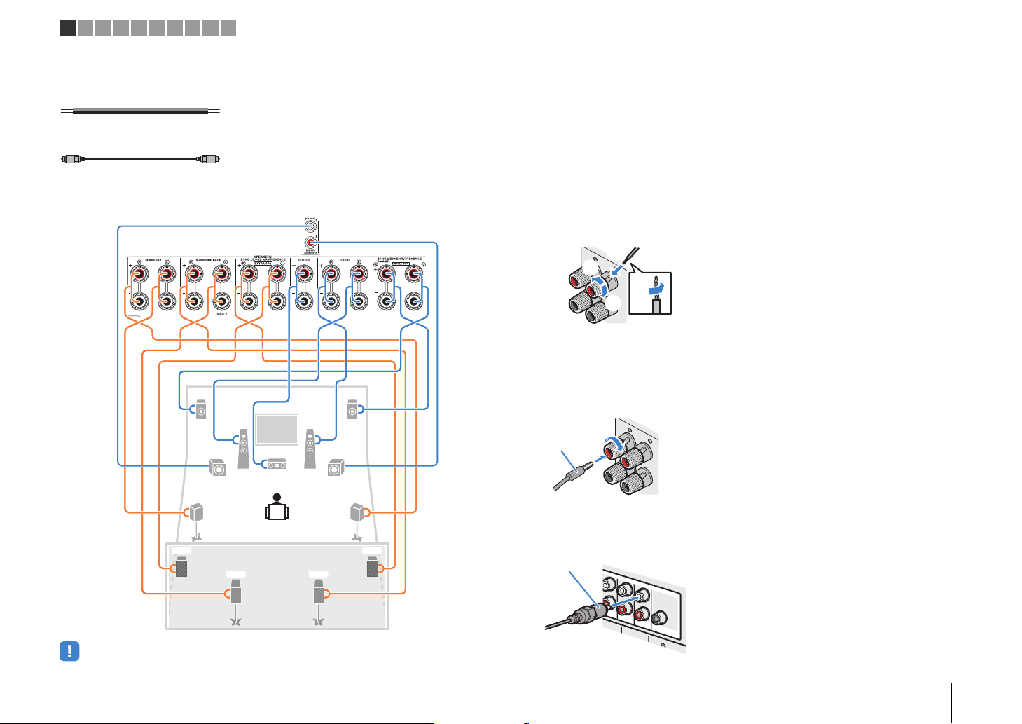
Cables necessary for connection (commercially available)
Speaker cables (x the number of speakers)
Audio pin cable (two for connecting two subwoofers)
Connection diagram
Refer to the following diagram and connect the speakers to the unit.
❑ Connecting speaker cables
Speaker cables have two wires. One is for connecting the negative (-) terminal of the
unit and the speaker, and the other is for the positive (+) terminal. If the wires are
colored to prevent confusion, connect the black wire to the negative and the other wire
to the positive terminal.
a Remove approximately 10 mm (3/8”) of insulation from the ends of the speaker cable, and
twist the bare wires of the cable firmly together.
b Loosen the speaker terminal.
c Insert the bare wires of the cable into the gap on the side (upper right or bottom left) of the
terminal.
d Tighten the terminal.
Using a banana plug
(U.S.A., Canada, Australia and General models only)
a Tighten the speaker terminal.
b Insert a banana plug into the end of the terminal.
+
a
• When using only one surround back speaker, connect it to the SINGLE jack (L side).
b
❑ Connecting the subwoofer (with built-in amplifier)
Use an audio pin cable to connect the subwoofer.
PREPARATIONS ➤ Connecting speakers En 23
Page 24
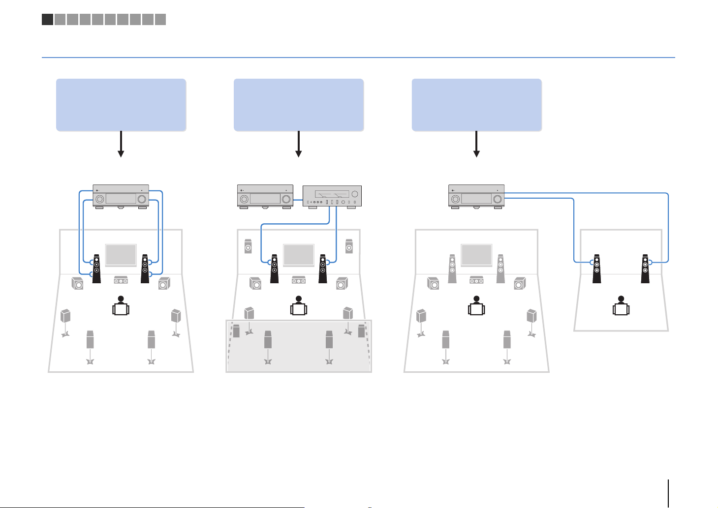
Using the four internal
amplifiers for front speakers to
have more high-quality sounds
(Example) (Example) (Example)
Bi-amp
connection
Combining with an external
power amplifier (Hi-Fi amplifier,
multi-channel amplifier, etc.) to
build an extended system
Using the excess internal
amplifiers for stereo speakers
in another room
External power
amplifier
Main zone
Zone2
Bi-amp connection Power-amp channel expansion Multi-zone configuration
1 2 3 4 5 6 7 8 9 10
Advanced speaker configuration
In addition to the basic speaker configuration (p.19), the unit also allows you to apply the following speaker configurations to enhance your system.
PREPARATIONS ➤ Connecting speakers En 24
Page 25
1 2 3 4 5 6 7 8 9 10
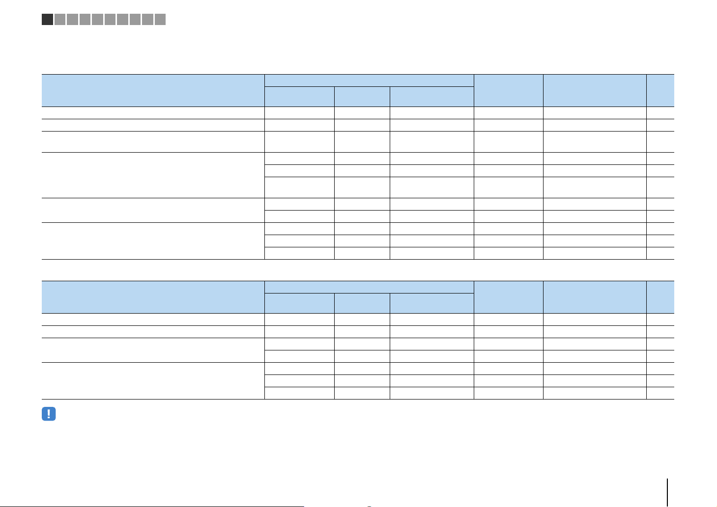
■ Available speaker configurations
(RX-A3040)
Main zone
Speaker configuration
Using a bi-amp connection in the main zone 7 7ch BI-AMP 26
Using a bi-amp connection in the main zone and multi-zone speakers 7 +1 room 7ch BI-AMP +1ZONE 26
Using a bi-amp connection in the main zone and power-amp channel
expansion (for presence channels)
Using power-amp channel expansion (for front and/or presence
channels)
Using power-amp channel expansion (for front channels) and
multi-zone speakers
Using multi-zone speakers
Output channel
(max)
11
11 Rear Presence 9ch +RP 27
11 Front 9ch +FRONT 28
11
9 Front +1 room 7ch +FRONT+1ZONE 29
7 Front +2 rooms 5ch +FRONT+2ZONE 29
7 +1 room 7ch +1ZONE 30
9 +1 room 9ch +1ZONE 30
7 +2 rooms 7ch +2ZONE 31
Bi-amp
External power
amplifier (required)
Front presence
Rear presence
Front presence
Rear presence
(RX-A2040)
Main zone
Speaker configuration
Using a bi-amp connection in the main zone 7 7ch BI-AMP 26
Using a bi-amp connection in the main zone and multi-zone speakers 7 +1 room 7ch BI-AMP +1ZONE 26
Using power-amp channel expansion (for front channels) and
multi-zone speakers
Using multi-zone speakers
Output channel
(max)
9 Front +1 room 7ch +FRONT+1ZONE 29
7 Front +2 rooms 5ch +FRONT+2ZONE 29
7 +1 room 7ch +1ZONE 30
9 +1 room 9ch +1ZONE 30
7 +2 rooms 7ch +2ZONE 31
Bi-amp
External power
amplifier (required)
Multi-zone Power Amp Assign (p.124) Page
7ch BI-AMP +FP+RP 27
7ch +FP+RP 28
Multi-zone Power Amp Assign (p.124) Page
• When applying one of these configurations, you need to configure the “Power Amp Assign” setting (p.124)
in the “Setup” menu.
• When applying a multi-zone configuration, you can select a zone (Zone2 or Zone3) to be assigned to the
EXTRA SP 1–2 jacks in “Power Amp Assign” (p.124) in the “Setup” menu. By default, Zone2 is assigned to
the EXTRA SP 1 jacks and Zone3 is assigned to the EXTRA SP 2 jacks. The following explanation is based
on the assumption that you have not changed the default zone assignments.
PREPARATIONS ➤ Connecting speakers En 25
Page 26
1
3
45
99
2
67
Bi-amp
Speaker Connect to
12 FRONT and EXTRA SP 1 (bi-amp connection)
3 CENTER
45 SURROUND
67 SURROUND BACK
ER (not used)
TY (not used)
9 SUBWOOFER 1–2
21
12
3
4
6
99
7
5
Bi-amp
Main zone
Zone3
• When Zone3 output is enabled (p.101), the surround back speakers in the main zone do not output sound.
Speaker Connect to
12 FRONT and EXTRA SP 1 (bi-amp connection)
3 CENTER
45 SURROUND
67 SURROUND BACK
ER (not used)
TY (not used)
9 SUBWOOFER 1–2
Zone3 speakers EXTRA SP 2
1 2 3 4 5 6 7 8 9 10
❑ 7ch BI-AMP ❑ 7ch BI-AMP +1ZONE
PREPARATIONS ➤ Connecting speakers En 26
Page 27
1
3
45
99
2
ER
6 7
YT
Bi-amp
via external amp
via external amp
via
external amp
via
external amp
• When this configuration is applied, you cannot utilize the ZONE OUT/PRE OUT jacks for connecting
external amplifiers for Zone2 and Zone3 (p.98).
Speaker Connect to
12 FRONT and EXTRA SP 1 (bi-amp connection)
3 CENTER
45 SURROUND
67 SURROUND BACK
ER F.PRESENCE (PRE OUT) via external power amplifier
TY R.PRESENCE (PRE OUT) via external power amplifier
9 SUBWOOFER 1–2
1
3
45
99
2
ER
6 7
YT
via
external amp
via
external amp
• When this configuration is applied, you cannot utilize the ZONE OUT/PRE OUT jacks for connecting an
external amplifier for Zone3 (p.98).
Speaker Connect to
12 FRONT
3 CENTER
45 SURROUND
67 SURROUND BACK
ER EXTRA SP 1
TY R.PRESENCE (PRE OUT) via external power amplifier
9 SUBWOOFER 1–2
1 2 3 4 5 6 7 8 9 10
❑ 7ch BI-AMP +FP+RP (RX-A3040 only) ❑ 9ch +RP (RX-A3040 only)
PREPARATIONS ➤ Connecting speakers En 27
Page 28
1
3
45
99
2
ER
6 7
YT
via external amp
• When this configuration is applied, you cannot utilize the ZONE OUT/PRE OUT jacks for connecting an
external amplifier for Zone3 (p.98).
Speaker Connect to
12 FRONT (PRE OUT) via external power amplifier
3 CENTER
45 SURROUND
67 SURROUND BACK
ER EXTRA SP 1
TY EXTRA SP 2
9 SUBWOOFER 1–2
1
3
45
99
2
ER
6 7
YT
via external amp
via external amp
via
external amp
via
external amp
• When this configuration is applied, you cannot utilize the ZONE OUT/PRE OUT jacks for connecting
external amplifiers for Zone2 and Zone3 (p.98).
Speaker Connect to
12 FRONT
3 CENTER
45 SURROUND
67 SURROUND BACK
ER F.PRESENCE (PRE OUT) via external power amplifier
TY R.PRESENCE (PRE OUT) via external power amplifier
9 SUBWOOFER 1–2
1 2 3 4 5 6 7 8 9 10
❑ 9ch +FRONT (RX-A3040 only) ❑ 7ch +FP+RP (RX-A3040 only)
PREPARATIONS ➤ Connecting speakers En 28
Page 29
21
1
E
2
3
4
6
99
7
5
R
via external amp
Main zone
Zone3
Speaker Connect to
12 FRONT (PRE OUT) via external power amplifier
3 CENTER
45 SURROUND
67 SURROUND BACK
ER EXTRA SP 1
TY (not used)
9 SUBWOOFER 1–2
Zone3 speakers EXTRA SP 2
12
3
4
6
99
7
5
12
12
Zone2
Zone3
Main zone
via external amp
Speaker Connect to
12 FRONT (PRE OUT) via external power amplifier
3 CENTER
45 SURROUND
67 SURROUND BACK
ER (not used)
TY (not used)
9 SUBWOOFER 1–2
Zone2 speakers EXTRA SP 1
Zone3 speakers EXTRA SP 2
1 2 3 4 5 6 7 8 9 10
❑ 7ch +FRONT+1ZONE ❑ 5ch +FRONT+2ZONE
PREPARATIONS ➤ Connecting speakers En 29
Page 30
21
12
3
4
6
99
7
5
Main zone
Zone2
Speaker Connect to
12 FRONT
3 CENTER
45 SURROUND
67 SURROUND BACK
ER (not used)
TY (not used)
9 SUBWOOFER 1–2
Zone2 speakers EXTRA SP 1
21
1
E
2
3
4
6
99
7
5
R
Main zone
Zone3
• When Zone3 output is enabled (p.101), the surround back speakers in the main zone do not output sound.
Speaker Connect to
12 FRONT
3 CENTER
45 SURROUND
67 SURROUND BACK
ER EXTRA SP 1
TY (not used)
9 SUBWOOFER 1–2
Zone3 speakers EXTRA SP 2
1 2 3 4 5 6 7 8 9 10
❑ 7ch +1ZONE ❑ 9ch +1ZONE
PREPARATIONS ➤ Connecting speakers En 30
Page 31
12
3
4
6
99
7
5
12
12
Zone2
Zone3
Main zone
• When Zone3 output is enabled (p.101), the surround back speakers in the main zone do not output sound.
Speaker Connect to
12 FRONT
3 CENTER
45 SURROUND
67 SURROUND BACK
ER (not used)
TY (not used)
9 SUBWOOFER 1–2
Zone2 speakers EXTRA SP 1
Zone3 speakers EXTRA SP 2
1 2 3 4 5 6 7 8 9 10
❑ 7ch +2ZONE
PREPARATIONS ➤ Connecting speakers En 31
Page 32

12
3
9
45
9
The unit (rear)
1
4
6
2
5
7
3
12
12
The unit (rear)
Main zone
Zone2
Zone3
1 2 3 4 5 6 7 8 9 10
■
Connecting front speakers that support bi-amp connections
When using front speakers that support bi-amp connections, connect them to the
FRONT terminals and EXTRA SP 1 terminals.
To enable the bi-amp function, configure the “Power Amp Assign” setting (p.124) in the
“Setup” menu after connecting the power cable to an AC wall outlet.
■ Connecting Zone2/3 speakers
When using Zone2/3 speakers, connect them to the EXTRA SP 1–2 terminals.
To utilize the EXTRA SP 1–2 terminals for Zone2/3 speakers, configure the “Power Amp
Assign” setting (p.124) in the “Setup” menu after connecting the power cable to an AC
wall outlet.
• The FRONT terminals and EXTRA SP 1 terminals output the same signals.
Caution
• Before making bi-amp connections, remove any brackets or cables that connect a woofer with a
tweeter. Refer to the instruction manual of the speakers for details. If you are not making bi-amp
connections, make sure that the brackets or cables are connected before connecting the speaker
cables.
• You can select a zone (Zone2 or Zone3) to be assigned to the EXTRA SP 1–2 jacks in “Power Amp Assign”
(p.124) in the “Setup” menu. By default, Zone2 is assigned to the EXTRA SP 1 jacks and Zone3 is
assigned to the EXTRA SP 2 jacks.
• You can also connect Zone2 and Zone3 speakers using an external amplifier (p.98).
PREPARATIONS ➤ Connecting speakers En 32
Page 33
321 4 56
The unit (rear)
MAIN IN
R
L
R
L
R
The unit (rear)
PRE OUT (FRONT) jacks
Main input jack
Amplifier with
volume control
bypass
(such as A-S3000)
1 2 3 4 5 6 7 8 9 10
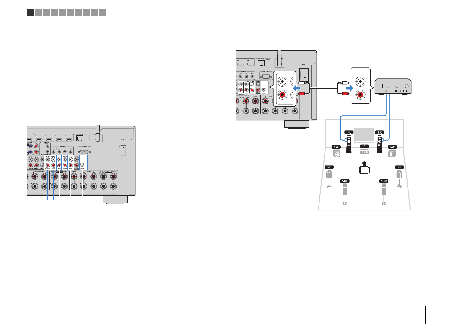
■ Connecting an external power amplifier
When connecting an external power amplifier to enhance speaker output, connect the
input jacks of the power amplifier to the PRE OUT jacks of the unit. The same channel
signals are output from the PRE OUT jacks as from their corresponding SPEAKERS
terminals.
Caution
• To prevent the generation of loud noises or abnormal sounds, make sure the followings before making
connections.
– Remove the power cable of the unit and turn off the external power amplifier before connecting them.
– When using the PRE OUT jacks, do not connect speakers to the corresponding SPEAKERS terminals.
– When using a pre-main amplifier that does not have the volume control bypass, turn up the volume of
the pre-main amplifier enough and fix it. In this case, do not connect other devices (except the unit) to
the pre-main amplifier.
1 F.PRESENCE jacks (RX-A3040 only)
Output front presence channel audio signals or Zone2 audio signals depending on the “Power
Amp Assign” setting (p.124).
2 R.PRESENCE jacks (RX-A3040 only)
Output rear presence channel audio signals or Zone3 audio signals depending on the “Power
Amp Assign” setting (p.124).
3 FRONT jacks
Output front channel sounds.
4 SURROUND jacks
Output surround channel sounds.
5 SUR. BACK jacks
Output surround back channel sounds. When using only one surround back speaker, connect
the external amplifier to the SINGLE jack (L side).
6 CENTER jack
Outputs center channel sounds.
(Example)
Connecting front speakers via an external power amplifier
PR
SU
FRONT
About external power amplifiers
We recommend using power amplifiers that meet the following conditions.
• With unbalanced inputs
• With volume control bypass (or without volume control circuit)
• Output power: 100 W or more (6 to 8 )
PREPARATIONS ➤ Connecting speakers En 33
Page 34
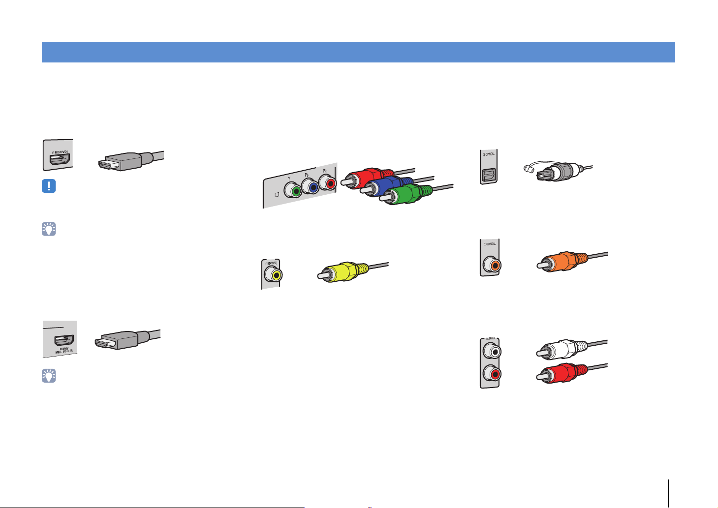
Input/output jacks and cables
AV 1
HDMI cable
MHL or HDMI cable
COMPONEN
AV 1
A
Component video cable
Video pin cable
Digital optical cable
Digital coaxial cable
Stereo pin cable
■ Video/audio jacks
❑ HDMI jacks
Transmit digital video and digital sound through a single
jack. Use an HDMI cable.
• Use a 19-pin HDMI cable with the HDMI logo. We recommend using
a cable less than 5.0 m (16.4 ft) long to prevent signal quality
degradation.
• The unit’s HDMI jacks support the HDMI Control, Audio Return
Channel (ARC), and 3D and 4K Ultra HD video transmission
features.
• Use high speed HDMI cables to enjoy 3D or 4K Ultra HD videos.
❑ HDMI/MHL jack
Transmits digital video and digital sound. Use an MHL
or HDMI cable.
■ Video jacks
❑ COMPONENT VIDEO jacks
Transmit video signals separated into three
components: luminance (Y), chrominance blue (P
and chrominance red (P
R). Use a component video
cable with three plugs.
❑ VIDEO jacks
Transmit analog video signals. Use a video pin cable.
AV 1
B),
■ Audio jacks
❑ OPTICAL jacks
Transmit digital audio signals. Use a digital optical
cable. Remove the tip protector (if available) before
using the cable.
❑ COAXIAL jacks
Transmit digital audio signals. Use a digital coaxial
cable.
❑ AUDIO jacks
Transmit analog stereo audio signals. Use a stereo pin
cable (RCA cable).
• The VIDEO AUX jack on the front panel of the unit supports both
MHL and HDMI connections. Use a cable that matches the jack on
your MHL-compatible mobile device. For details on an MHL
connection, see “MHL connection” (p.41). When connecting an
HDMI-compatible playback device to the VIDEO AUX jack, use an
HDMI cable.
PREPARATIONS ➤ Input/output jacks and cables En 34
Page 35
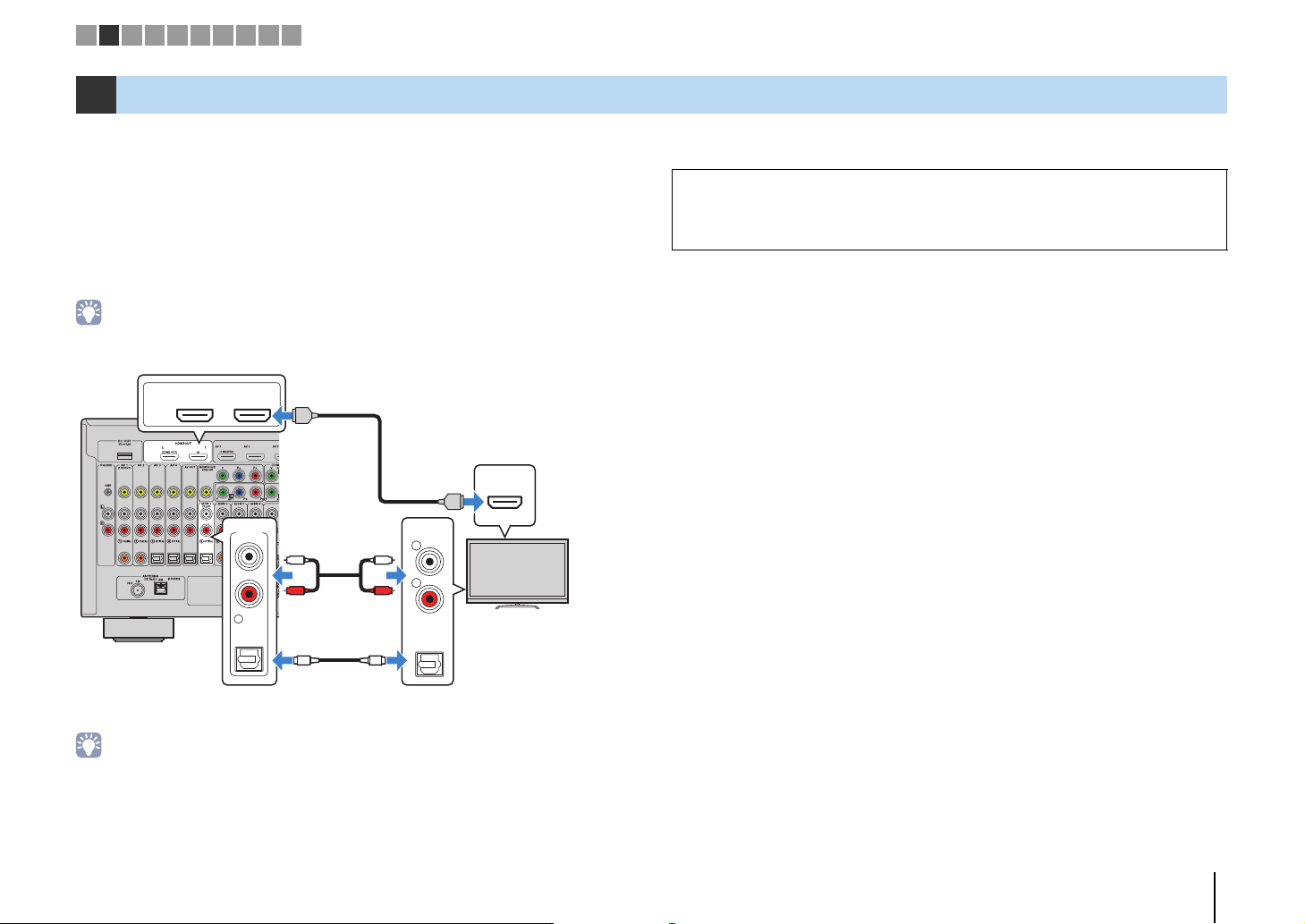
The unit
(rear)
HDMI OUT jack
AUDIO 1
(OPTICAL or AUDIO) jacks
Audio output
(digital optical or analog stereo)
TV
HDMI input
1 2 3 4 5 6 7 8 9 10
2 Connecting a TV
Connect a TV to the unit so that video input to the unit can be output to the TV.
You can also enjoy playback of TV audio on the unit.
To maximize the performance of the unit, we recommend connecting a TV with an HDMI
cable.
■ HDMI connection
Connect the TV to the unit with an HDMI cable and an audio cable (digital optical or
stereo pin cable).
• You can connect another TV or a projector by using the HDMI OUT 2 jack (p.37).
HDMI OUT
(ZONE OUT)
ARC
AUDIO 1
(2 TV)
5
OPTICAL
12
HDMI
L
R
OO
L
R
AUDIO
L
R
OPTICAL
HDMI
HDMI
To use HDMI Control and ARC, you need to configure the HDMI settings on the unit. For
details on the settings, see “Information on HDMI” (p.168).
About Audio Return Channel (ARC)
• ARC allows audio signals to travel both ways. If you connect a TV that supports ARC to the unit with a
single HDMI cable, you can output video/audio to the TV or input TV audio to the unit.
• When using ARC, connect a TV with an HDMI cable that supports ARC.
• You do not make an audio cable connection between the TV and the unit in the following cases:
– If your TV supports Audio Return Channel (ARC)
– If you will receive TV broadcasts only from the set-top box
• If you connect a TV that suppor ts HDMI Control to the unit with an HDMI cable, you can control the unit’s
power and volume with the TV’s remote control.
PREPARATIONS ➤ Connecting a TV En 35
Page 36
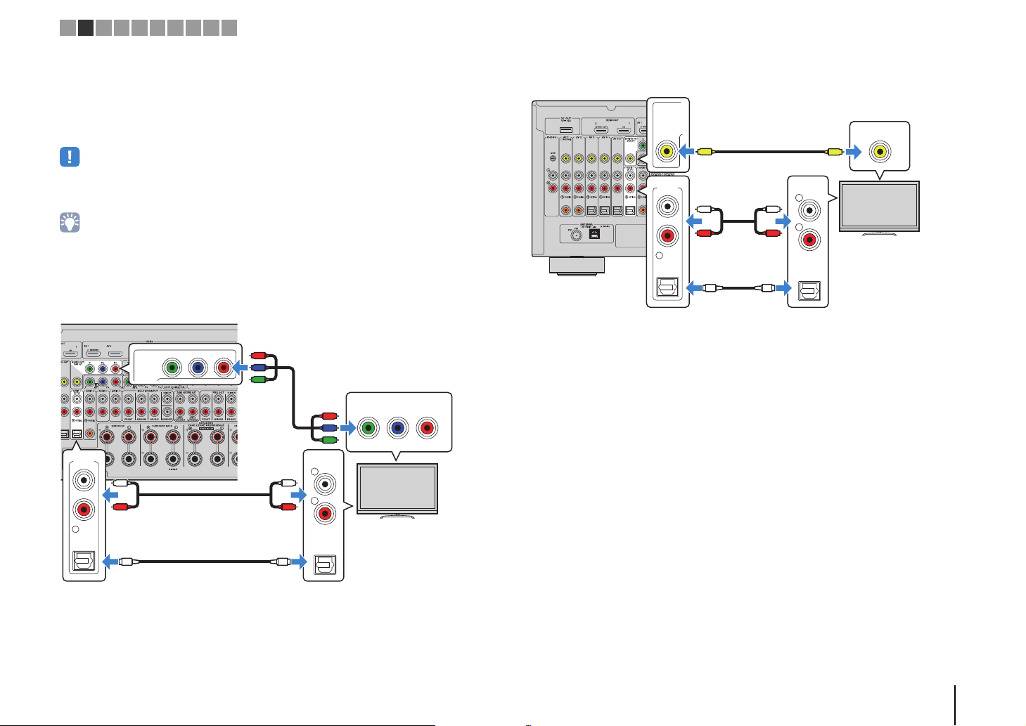
OPTICAL
AUDIO 1
(2 TV)
5
AUDIO
OPTICAL
R
L
YPB PR
COMPONENT VIDEO
PB PR
Y
MONITOR OUT/
ZONE OUT
OO
L
R
L
R
P
R
P
B
Y
P
R
P
B
Y
The unit
(rear)
MONITOR OUT
(COMPONENT VIDEO) jacks
Video input
(component video)
AUDIO 1
(OPTICAL or AUDIO) jacks
Audio output
(digital optical or analog stereo)
TV
OPTICAL
AUDIO 1
(2 TV)
5
AUDIO
OPTICAL
R
L
VIDEO
MONITOR OUT/
ZONE OUT
OO
L
R
L
R
V
V
The unit (rear)
MONITOR OUT (VIDEO) jack
Video input (composite video)
AUDIO 1
(OPTICAL or AUDIO)
jacks
Audio output
(digital optical or analog stereo)
TV
1 2 3 4 5 6 7 8 9 10
■ Component/composite video connection
When connecting any video device with a component video cable, connect the TV to
the MONITOR OUT (COMPONENT VIDEO) jacks.
When connecting any video device with a video pin cable, connect the TV to the
MONITOR OUT (VIDEO) jack.
• If you connect your TV to the unit with a cable other than HDMI, video input to the unit via HDMI cannot be
output to the TV.
• Operations with TV screen are available only when your TV is connected to the unit via HDMI.
• If you will receive TV broadcasts only from the set-top box, you do not need to make an audio cable
connection between the TV and the unit.
❑ COMPONENT VIDEO connection (with a component video cable)
❑ VIDEO (composite video) connection (with a video pin cable)
PREPARATIONS ➤ Connecting a TV En 36
Page 37
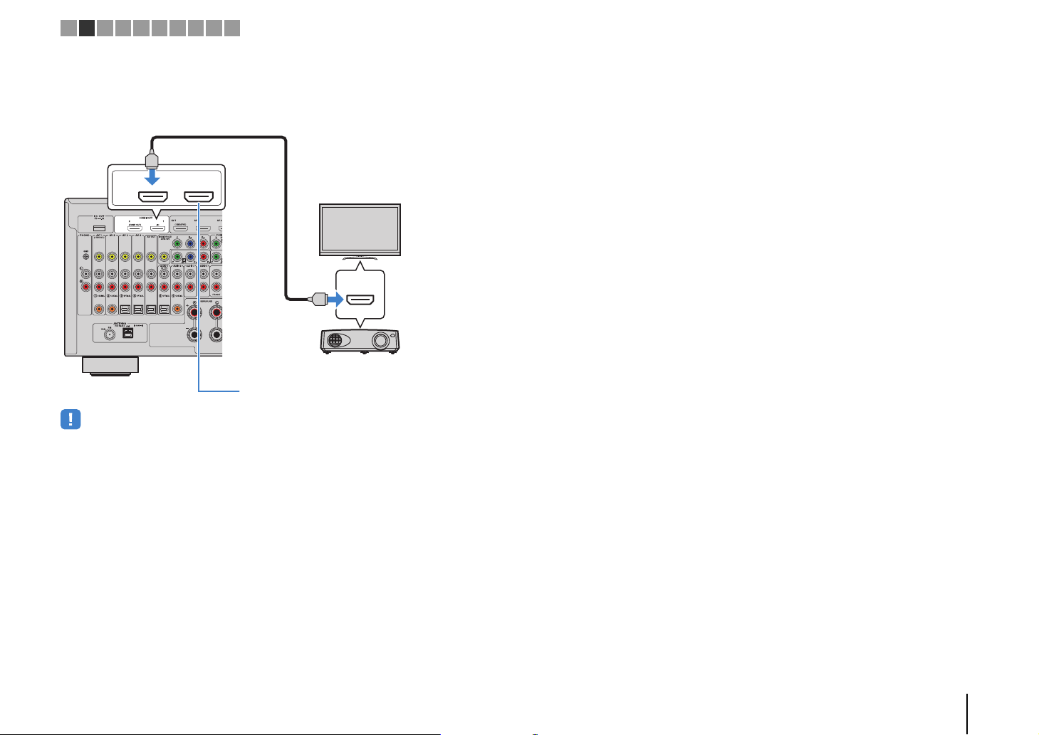
HDMI
HDMI OUT
ARC
(ZONE OUT)
12
HDMI
HDMI
The unit
(rear)
HDMI OUT 2 jack
HDMI input
Projector
TV (already connected)
TV
1 2 3 4 5 6 7 8 9 10
■ Connecting another TV or a projector
The unit has two HDMI output jacks. If you connect another TV or a projector to the unit
with an HDMI cable, you can switch the TV (or projector) to be used for watching
videos with the remote control (p.67).
• HDMI Control is not available on the HDMI OUT 2 jack.
• If you set “HDMI OUT2 Assign” (p.138) in the “Setup” menu to “Zone2” or “Zone4”, you can connect a video
monitor for Zone2 or Zone4 to the HDMI OUT 2 jack and enjoy videos and audio using the video monitor
(p.99).
PREPARATIONS ➤ Connecting a TV En 37
Page 38

HDMI
HDMI
HDMI
The unit (rear)
HDMI output
Video device
HDMI (AV 1–7) jacks
The unit (rear)
AV 1–3
(COMPONENT VIDEO) jacks
Video output
(component video)
Video device
Audio output
(any of digital coaxial, digital optical,
analog stereo)
Any of AV 1–2 (COAXIAL),
AV 3 (OPTICAL),
AV 1–3 (AUDIO) jacks
1 2 3 4 5 6 7 8 9 10
3 Connecting playback devices
The unit is equipped with a variety of input jacks including HDMI input jacks to allow
you to connect different types of playback devices. For information on how to connect
an iPod or a USB storage device, see the following pages.
• Connecting an iPod (p.83)
• Connecting a USB storage device (p.86)
Connecting video devices (such as BD/DVD players)
Connect video devices such as BD/DVD players, set-top boxes (STBs) and game
consoles to the unit. Depending on the video/audio output jacks available on your video
device, choose one of the following connections. We recommend using an HDMI
connection if the video device has an HDMI output jack.
• Videos input to the unit via HDMI cannot be output to a TV connected to the unit with a cable other than
HDMI. For details, refer to “Video signal flow” (p.166).
• The following explanation is based on the assumption that you have not changed the “Input Assignment”
setting (p.138) in the “Setup” menu. As necessary, you can assign the COMPONENT VIDEO (A , B , C ),
COAXIAL (a, b, f) and OPTICAL (c, d, e) jacks to another input source.
• If you make more than one audio connection for one input source, an audio signal played back on the unit
will be determined according to the “Audio Select” setting (p.110) in the “Option” menu.
■ HDMI connection
Connect a video device to the unit with an HDMI cable.
■ Component video connection
Connect a video device to the unit with a component video cable and an audio cable
(digital coaxial, digital optical or stereo pin cable). Choose a set of input jacks (on the
unit) depending on the audio output jacks available on your video device.
Output jacks on video device
Video Audio
Component video
CC
OO
L
R
Digital coaxial AV 1–2 (COMPONENT VIDEO + COAXIAL)
Digital optical AV 3 (COMPONENT VIDEO + OPTICAL)
Analog stereo AV 1–3 (COMPONENT VIDEO + AUDIO)
YPB PR
R
P
P
B
Y
Input jacks on the unit
R
P
P
B
Y
COAXIAL
OPTICAL
L
L
R
R
YPB PR
If you select the input source by pressing AV 1–7 on the remote control, the video/audio
played back on the video device will be output from the unit.
If you select the input source by pressing AV 1–3 on the remote control, the video/audio
played back on the video device will be output from the unit.
PREPARATIONS ➤ Connecting playback devices En 38
Page 39
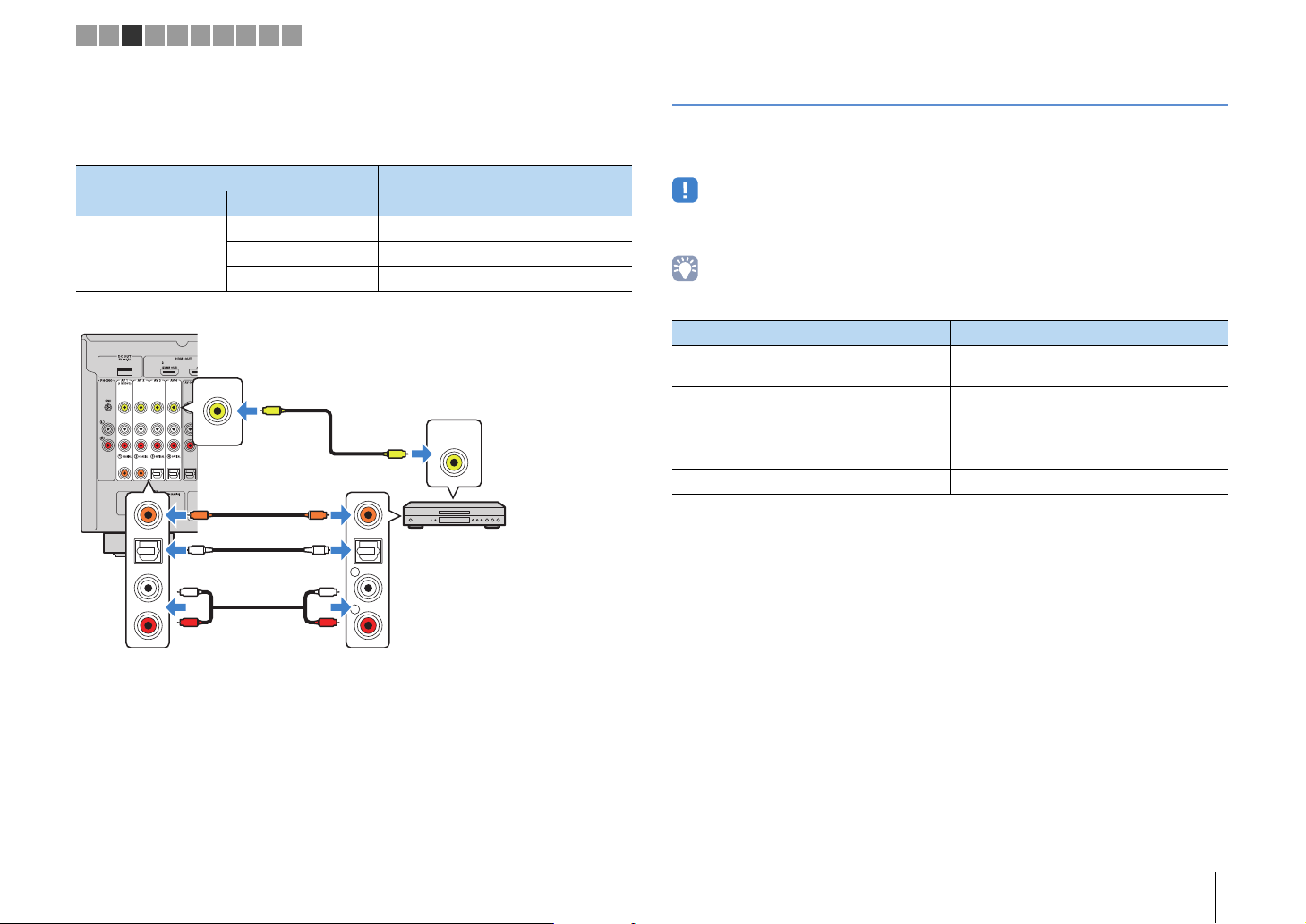
The unit (rear)
AV 1–4 (VIDEO) jacks
Video output
(composite video)
Video device
Audio output
(any of digital coaxial, digital optical,
analog stereo)
Any of AV 1–2 (COAXIAL),
AV 3–4 (OPTICAL),
AV 1–4 (AUDIO) jacks
1 2 3 4 5 6 7 8 9 10
■ Composite video connection
Connect a video device to the unit with a video pin cable and an audio cable (digital
coaxial, digital optical, or stereo pin cable). Choose a set of input jacks (on the unit)
depending on the audio output jacks available on your video device.
Output jacks on video device
Video Audio
Composite video
CC
OO
L
R
Digital coaxial AV 1–2 (VIDEO + COAXIAL)
Digital optical AV 3–4 (VIDEO + OPTICAL)
Analog stereo AV 1–4 (VIDEO + AUDIO)
V
COAXIAL
OPTICAL
L
L
R
R
Input jacks on the unit
VIDEO
V
Connecting audio devices (such as CD players)
Connect audio devices such as CD players, MD players, and a turntable to the unit.
Depending on the audio output jacks available on your audio device, choose one of the
following connections.
• The following explanation is based on the assumption that you have not changed the “Input Assignment”
setting (p.138) in the “Setup” menu. As necessary, you can assign the COAXIAL (a, b, f) and OPTICAL
(c, d, e) jacks to another input source.
• If you make more than one audio connection for one input source, an audio signal played back on the unit
will be determined according to the “Audio Select” setting (p.110) in the “Option” menu.
Audio output jacks on audio device Audio output jacks on the unit
Digital coaxial
Digital optical
Analog stereo
Turntable (PHONO) PHONO
AV 1–2 (COAXIAL)
AUDIO 2 (COAXIAL)
AV 3–4 (OPTICAL)
AUDIO 1 (OPTICAL)
AV 1–4 (AUDIO)
AUDIO 1–4 (AUDIO)
If you select the input source by pressing AV 1–4 on the remote control, the video/audio
played back on the video device will be output from the unit.
PREPARATIONS ➤ Connecting playback devices En 39
Page 40
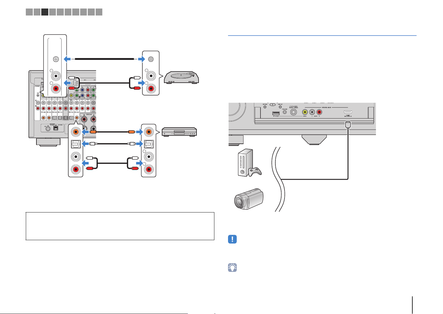
R
L
PHONO
GND
R
L
COAXIAL
OPTICAL
R
L
PHONO
GND
CC
L
R
L
R
OO
L
R
L
R
Audio output
(any of digital coaxial, digital optical,
analog stereo)
Any of AV 1–4, AUDIO 1–4
(COAXIAL, OPTICAL, AUDIO) jacks
The unit
(rear)
Audio device
PHONO jacks
Audio output
(PHONO)
Turntable
Ground lead
Game console
Camcorder
The unit (front)
1 2 3 4 5 6 7 8 9 10
If you select the input source by pressing AV 1–4, AUDIO 1–4 or PHONO on the remote
control, the audio played back on the audio device will be output from the unit.
When connecting a turntable
• The PHONO jack of the unit is compatible with an MM cartridge. To connect a turntable with a
low-output MC cartridge, use a boosting transformer.
• Connecting the turntable to the GND terminal of the unit may reduce noise in the signal.
Connecting to the jacks on the front panel
Use the VIDEO AUX jack to temporarily connect a playback device to the unit.
Use the USB jack to connect an iPod or a USB storage device. For details, see
“Connecting an iPod” (p.83) or “Connecting a USB storage device” (p.86).
Before making a connection, stop playback on the device and turn down the volume on
the unit.
❑ HDMI connection
Connect an HDMI-compatible device (such as game consoles and camcorders) to the
unit with an HDMI cable.
HDMI
If you select “V-AUX” as the input source by pressing V-AUX on the remote control, the
video/audio played back on the device will be output from the unit.
• To watch videos input to the VIDEO AUX (HDMI/MHL IN) jack, you need to connect your TV to the HDMI
OUT jack of the unit (p.35).
• You need to prepare an HDMI cable that matches the output jacks on your device.
• When “USB” is selected as the input source, video signals input to the VIDEO AUX jacks are output from
the HDMI OUT and MONITOR OUT (VIDEO) jacks by default. You can change the video out setting in
“Video Out” (p.110) in the “Option” menu.
PREPARATIONS ➤ Connecting playback devices En 40
Page 41

MHL
MHL
Mobile device
MHL output
The unit (front)
V RL
Game console
Camcorder
The unit (front)
1 2 3 4 5 6 7 8 9 10
❑ MHL connection
Connect an MHL-compatible mobile device (such as smartphones) to the unit with an
MHL cable. You can enjoy full HD videos and multichannel audio sources stored on the
mobile device. The VIDEO AUX (HDMI/MHL IN) jack of the unit enables you to input
videos and audio directly from the mobile device to the unit.
If you select “V-AUX” as the input source by pressing V-AUX, the video/audio played
back on the mobile device will be output from the unit.
• To watch videos input to the VIDEO AUX (HDMI/MHL IN) jack, you need to connect your TV to the HDMI
OUT jack of the unit (p.35).
• You need to prepare an MHL cable that matches the jack on your mobile device.
• If you cannot hear sounds played on the mobile device, check the volume of the mobile device.
• You can operate the mobile device using the menu operation keys, external device operation keys and
numeric keys on the remote control. However, some features may not be compatible, depending on the
mobile device or its application. In this case, operate the mobile device itself.
• If “Standby Through” (p.133) in the “Setup” menu is set to “On”, you can output mobile device videos/audio
to the TV or operate the mobile device using the remote control of the unit even when the unit is in standby
mode.
• The unit supplies power to the mobile device in the following conditions.
– The unit is turned on.
– The unit is in standby mode while “Standby Through” (p.133) in the “Setup” menu is set to “On”.
❑ Composite video/analog stereo connection
Connect a playback device (such as game consoles and camcorders) to the unit with a
video pin cable and a stereo pin cable.
If you select “V-AUX” as the input source by pressing V-AUX, the video/audio played
back on the device will be output from the unit.
• If you connect video devices to both the VIDEO AUX (HDMI/MHL IN) jack and VIDEO AUX
(VIDEO/AUDIO) jacks, the unit outputs video/audio input through the VIDEO AUX (HDMI/MHL IN) jack.
PREPARATIONS ➤ Connecting playback devices En 41
Page 42
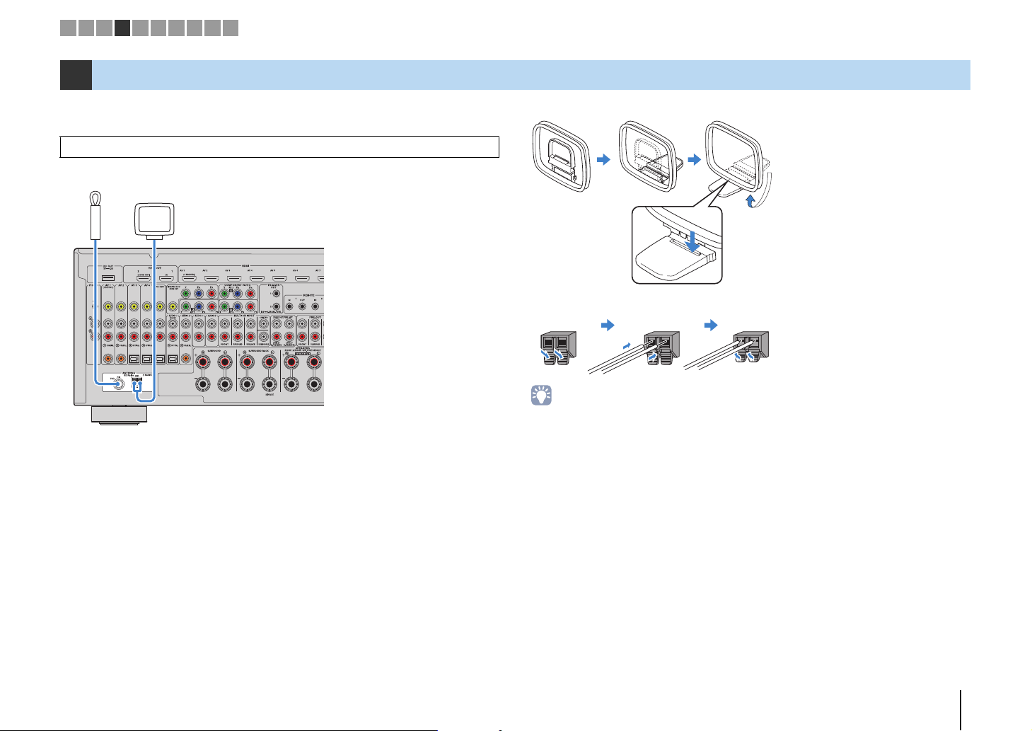
FM antenna
AM antenna
The unit (rear)
Hold down Insert Release
1 2 3 4 5 6 7 8 9 10
4 Connecting the FM/AM antennas
Connect the supplied FM/AM antennas to the unit.
Fix the end of the FM antenna to a wall, and place the AM antenna on a flat surface.
• The location of the antenna jacks varies depending on the region of purchase.
Assembling the AM antenna
Connecting the AM antenna
• Unwind only the length of cable needed from the AM antenna unit.
• The wires of the AM antenna have no polarity.
PREPARATIONS ➤ Connecting the FM/AM antennas En 42
Page 43

Network Attached Storage
(NAS)
Internet
Modem
Router
Network cable
PC
The unit (rear)
Mobile device
(such as iPod touch
and iPhone)
1 2 3 4 5 6 7 8 9 10
5 Connecting a network cable or the wireless antenna
Connect the unit to a router (access point) with a network cable, or connect the
supplied wireless antenna for establishing a wireless network connection.
You can enjoy Internet radio or music files stored on media servers, such as PCs and
Network Attached Storage (NAS), on the unit.
Connecting the network cable
Connect the unit to your router with a commercially-available STP network cable (CAT-5
or higher straight cable).
WAN
LAN
• If you are using a router that supports DHCP, you do not need to configure any network settings for the unit,
as the network parameters (such as the IP address) will be assigned automatically to it. You only need to
configure the network settings if your router does not support DHCP or if you want to configure the network
parameters manually (p.134).
• You can check whether the network parameters (such as IP address) are properly assigned to the unit in
“Network” (p.143) in the “Information” menu.
Connecting the wireless antenna
Connect the supplied wireless antenna to the unit for establishing a wireless network
connection.
For information on how to connect the unit to a network device wirelessly, see
“Connecting to a network device wirelessly” (p.59).
WIRELESS
a
a Rotate the antenna clockwise.
b Stand the antenna up straight.
• Do not connect the antenna other than the supplied one.
• Do not apply excessive force on the antenna. Doing so may damage it.
• When packing the unit, remove the antenna to prevent damage.
b
• Some security software installed on your PC or the firewall settings of network devices (such as a router)
may block the access of the unit to the network devices or the Internet. In these cases, configure the
security software or firewall settings appropriately.
• Each ser ver must be connected to the same subnet as the unit.
• To use the service via the Internet, broadband connection is strongly recommended.
PREPARATIONS ➤ Connecting a network cable or the wireless antenna En 43
Page 44

VIDEO
AUDIO
OPTICAL
R
L
AV OUT
V
L
R
L
R
OO
V
The unit (rear)
AV OUT jacks
Video/audio input
Video/audio
recording device
MULTI CH INPUT
CENTER
SUBWOOFER
FRONT
SURROUND SUR. BACK
L
R
L
R
L
R
The unit (rear)
MULTI CH
INPUT jacks
Channel output
(Center)
Device with analog
multi-channel output
(Subwoofer)
(Surround
back)
(Surround)
(Front)
1 2 3 4 5 6 7 8 9 10
6 Connecting other devices
Connecting recording devices
You can connect video/audio recording devices to the AV OUT jacks. These jacks
output video/audio signals selected as the input.
• The AV OUT jacks cannot output video/audio signals input through the HDMI or COMPONENT VIDEO
jacks.
• Be sure to use the AV OUT jacks only for connecting recording devices.
Connecting a device with analog multi-channel output
You can connect an analog multi-channel output device such as a DVD player and an
SACD player to the MULTI CH INPUT jacks.
If you select “MULTI CH” as the input source by pressing MULTI on the remote control,
the audio played back on the device will be output from the unit.
• You can select a video source to be displayed when “MULTI CH” is selected as the input source using
“Video Out” (p.110) in the “Option” menu. When connecting a video device (such as a DVD player) to the
MULTI CH INPUT jacks, use the input jack specified in “Video Out” for the video connection.
• Since the unit does not redirect signals input to the MULTI CH INPUT jacks to accommodate for missing
speakers, make appropriate settings on the external device (such as a DVD player) that suit to the speaker
configuration.
• When “MULTI CH” is selected as the input source, sound mode selection and tone control adjustment are
not available.
PREPARATIONS ➤ Connecting other devices En 44
Page 45
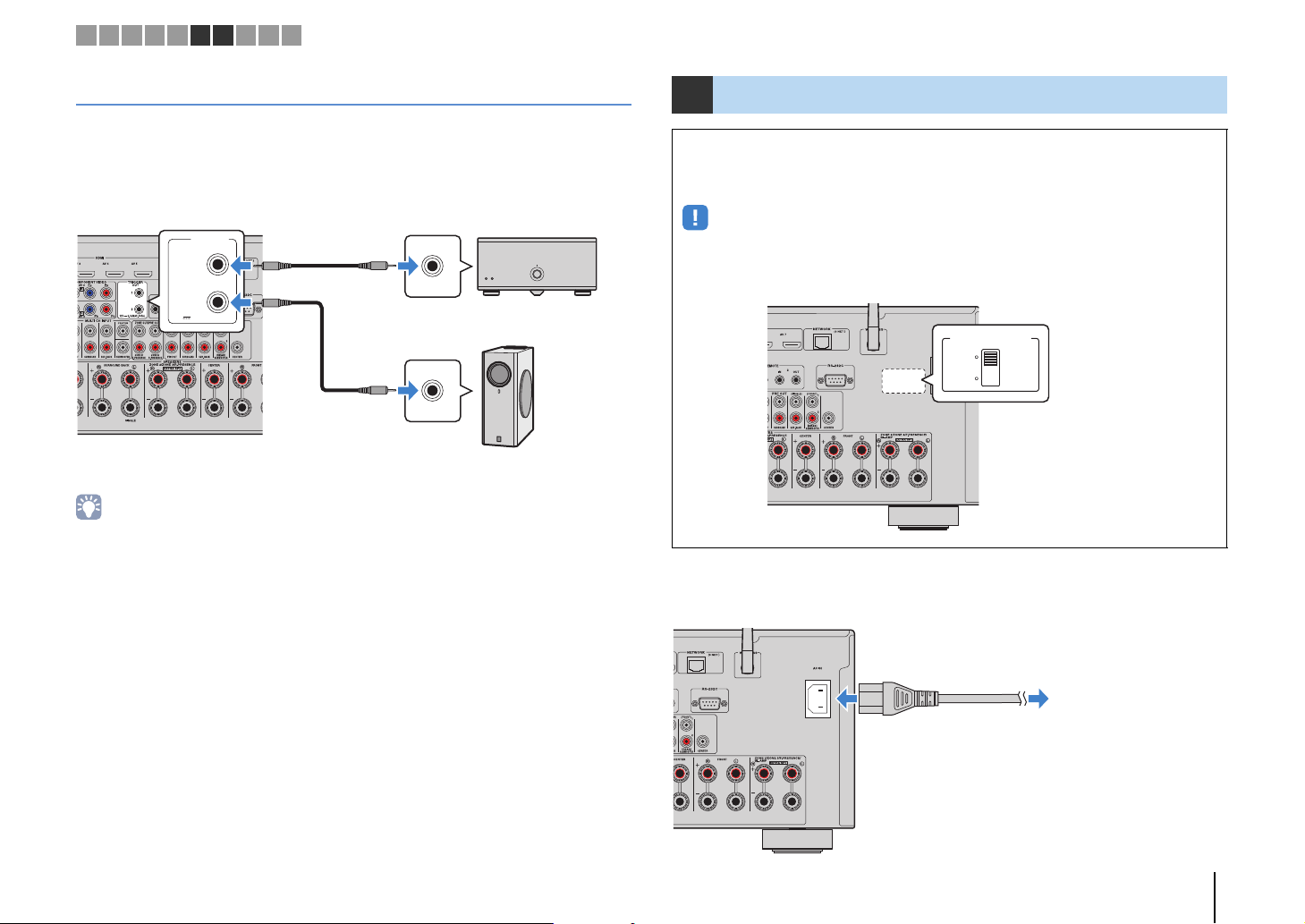
The unit (rear)
TRIGGER OUT
1–2 jacks
System
connection
input
Yamaha
subwoofer
Power amplifier
(such as MX-A5000)
Trigger In
(+12V)
VOLTAGE SELECTOR
220V240V
110V120V
The unit (rear)
VOLTAGE SELECTOR
To an AC wall outlet
The unit (rear)
1 2 3 4 5 6 7 8 9 10
Connecting a device compatible with the trigger function
The trigger function can control an external device in conjunction with operating the
unit (such as powering on/off and input selection). If you have a Yamaha subwoofer that
supports a system connection or a device with a trigger input jack, you can use the
trigger function by connecting the external device to one of the TRIGGER OUT jacks.
TRIGGER
OUT
1
2
12V 0.1A
MAX. TOTAL
• You can configure the trigger function settings in “Trigger Output1” and “Trigger Output2” (p.139) in the
“Setup” menu.
7 Connecting the power cable
Before connecting the power cable (General model only)
Set the switch position of VOLTAGE SELECTOR according to your local voltage.
Voltages are AC 110–120/220–240 V, 50/60 Hz.
• Make sure you set VOLTAGE SELECTOR of the unit BEFORE plugging the power cable into an AC
wall outlet. Improper setting of VOLTAGE SELECTOR may cause damage to the unit and create a
potential fire hazard.
After all the connections are complete, connect the supplied power cable to the unit
and then to an AC wall outlet.
PREPARATIONS ➤ Connecting the power cable En 45
Page 46

1 2 3 4 5 6 7 8 9 10
RECEIVER z
ON SCREEN
Cursor keys
ENTER
8 Selecting an on-screen menu language
Select the desired on-screen menu language from English,
Japanese, French, German, Spanish, Russian, Italian and Chinese.
Press RECEIVER z to turn on the unit.
1
Turn on the TV and switch the TV input to display
2
video from the unit.
Press ON SCREEN.
3
Use the cursor keys to select “Setup” and press
4
ENTER.
Use the cursor keys (e/r) to select “Language” and
5
the cursor keys (q/w) to select the desired
language.
To confirm the setting, press ENTER.
6
To exit from the menu, press ON SCREEN.
7
• The information on the front display is provided in English only.
PREPARATIONS ➤ Selecting an on-screen menu language En 46
Page 47
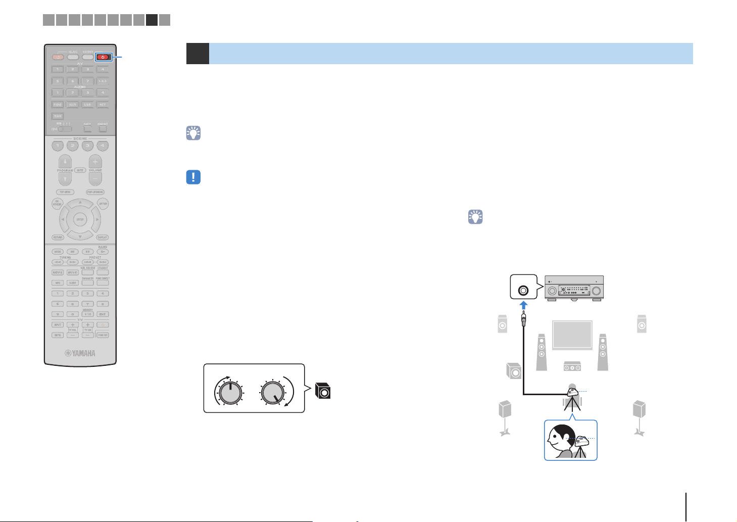
VOLUME HIGH CUT
CROSSOVER/
MIN MAXMIN MAX
9
YPAO MIC
9
12
3
45
ER
The unit (front)
YPAO
microphone
Ear height
YPAO MIC
jack
1 2 3 4 5 6 7 8 9 10
RECEIVER z
9 Optimizing the speaker settings automatically (YPAO)
The Yamaha Parametric room Acoustic Optimizer (YPAO) function
detects speaker connections, measures the distances from them to
your listening position(s), and then automatically optimizes the
speaker settings, such as volume balance and acoustic
parameters, to suit your room.
• The YPAO function of the unit adopts the YPAO-R.S.C. (Reflected Sound Control)
technology that enables to create natural sound fields like a room specifically
designed for acoustic perfection.
• Note the following regarding YPAO measurement.
– Test tones are output at high volume and may surprise or frighten small children.
– Test tone volume cannot be adjusted.
– Keep the room as quiet as possible.
– Stay in a corner of the room behind the listening position so that you do not
become an obstacle between speakers and the YPAO microphone.
– Do not connect headphones.
Press RECEIVER z to turn on the unit.
1
Turn on the TV and switch the TV input to display
2
video from the unit.
Turn on the subwoofer and set the volume to half. If
3
the crossover frequency is adjustable, set it to
maximum.
According to your speaker configuration, configure
4
the “Power Amp Assign” setting (p.124) in the
“Setup” menu.
For the basic speaker configuration (p.19): set to “Basic”
(default).
For any of the advanced speaker configurations (p.24): set
to the appropriate setting.
Place the YPAO microphone at your listening
5
position and connect it to the YPAO MIC jack on the
front panel.
• Place the YPAO microphone at your listening position (same height as your
ears). We recommend the use of a tripod as a microphone stand. You can
use the tripod screws to stabilize the microphone.
PREPARATIONS ➤ Optimizing the speaker settings automatically (YPAO) En 47
Page 48

1 2 3 4 5 6 7 8 9 10
RECEIVER
Cursor keys
ENTER
The following screen appears on the TV.
• To cancel the operation, disconnect the YPAO microphone before starting
the measurement.
If desired, select the measuring options.
6
a Use the cursor keys to select “Multi Position” (p.48) or
“Angle/Height” (p.49) (RX-A3040 only) and press ENTER.
b Use the cursor keys to select a setting and then press ENTER.
• If the cursor keys do not work, the remote control may be set to operate
external devices. In this case, press RECEIVER and then use the cursor
keys.
This completes the preparations. See the following page to start the
measurement.
When “Multi Position” is set to “Yes”:
“Measuring at multiple listening positions (multi measure)” (p.53)
When “Multi Position” is set to “No”:
“Measuring at one listening position (single measure)” (p.50)
❑ Multi Position
Selects multi measure or single measure.
Settings
Select this option if you will have several listening
Yes
No (default)
• If you perform the multi measure, the speaker settings will be optimized for you to
enjoy surround sound in a wider space.
• If you perform the multi measure, first place the YPAO microphone at the listening
position you will be seated most frequently.
positions or if you want others to enjoy surround sound.
You can take measurements at up to 8 different positions
in the room. The speaker settings will be optimized to
suit the area defined by those positions (multi measure).
Select this option if your listening position will always be
fixed. Take the measurements at only one position. The
speaker settings will be optimized to suit that position
(single measure).
PREPARATIONS ➤ Optimizing the speaker settings automatically (YPAO) En 48
Page 49
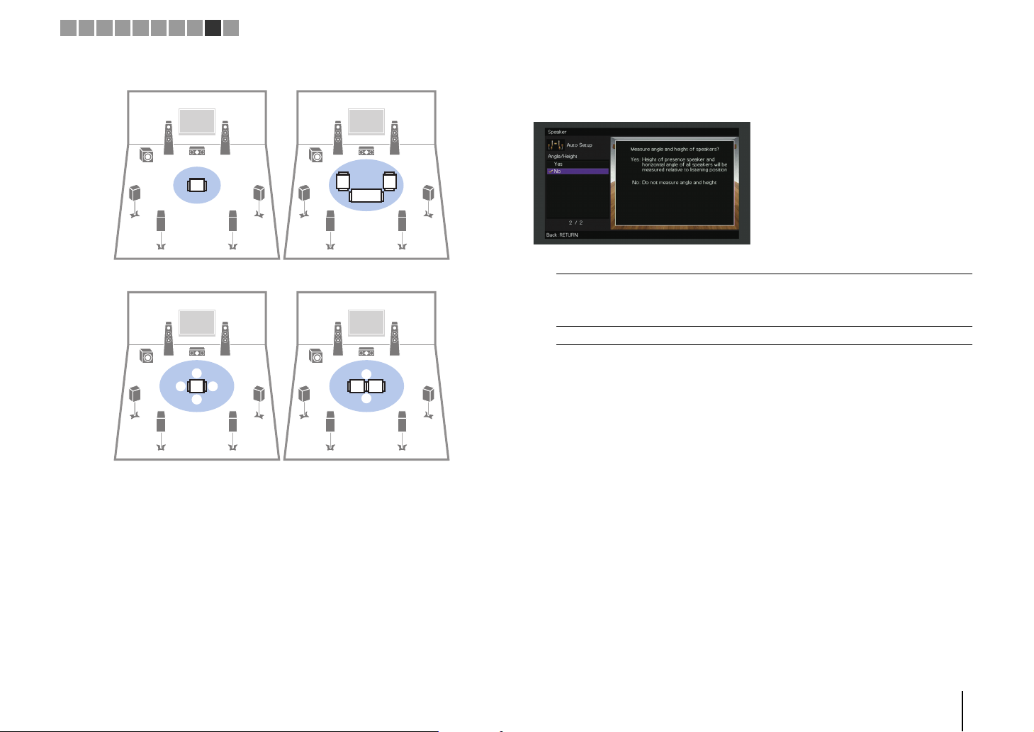
a b
a
a
b
cde
c
d
de
bac
Multi measure
(5 listening positions)
Multi measure
(2 listening positions + front/back)
Multi measure
(1 listening position + front/back/left/right)
Single measure
1 2 3 4 5 6 7 8 9 10
❑ Angle/Height
(RX-A3040 only)
Enables/disables the angle/height measurement.
Settings
Enables the angle/height measurement. The unit will measure angle of
Yes
No (default) Disables the angle/height measurement.
each speaker and height of the presence speakers at the listening
position, and correct the speaker parameters so that CINEMA DSP can
create more effective sound fields.
PREPARATIONS ➤ Optimizing the speaker settings automatically (YPAO) En 49
Page 50

Microphone base
Pole
1 2 3 4 5 6 7 8 9 10
Cursor keys
ENTER
RETURN
Measuring at one listening position (single measure)
When “Multi Position” is set to “No”, follow the procedure below for
measurement. It takes about 5 minutes to perform the
measurement.
• If any error message (such as E-1) or warning message (such as W-1) appears,
see “Error messages” (p.57) or “Warning messages” (p.58).
• (RX-A3040 only)
Do not use the microphone base until the corresponding message appear on the
TV.
To start the measurement, use the cursor keys to
1
select “Measure” and press ENTER.
The measurement will start in 10 seconds. Press ENTER
again to start the measurement immediately.
• To cancel the measurement temporarily, press RETURN.
The following screen appears on the TV when the
measurement finishes.
(RX-A2040)
(RX-A3040 [when angle/height measurement is disabled])
Proceed to Step 3.
(RX-A3040 [when angle/height measurement is enabled])
Proceed to Step 2.
Perform the angle/height measurement.
2
a Use the cursor keys to select “YES” and press ENTER.
Select “NO” to cancel the angle/height measurement.
b Attach the supplied pole to the center of the microphone base.
PREPARATIONS ➤ Optimizing the speaker settings automatically (YPAO) En 50
Page 51
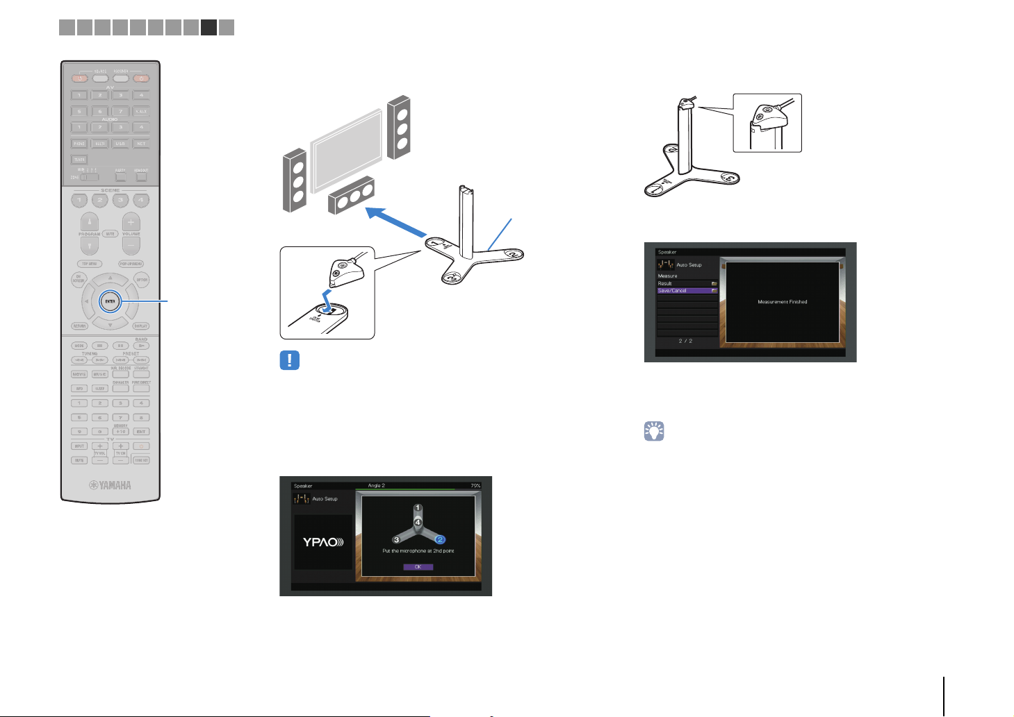
Microphone base
1 2 3 4 5 6 7 8 9 10
ENTER
c Place the microphone base at the listening position and set the
YPAO microphone to the position “1”.
• We recommend using a tripod to place the microphone base at ear height.
Use the tripod screws to fix the microphone base in place.
• Do not move the microphone base until the fourth angle measurement
finishes.
d Press ENTER to start the first angle measurement.
The following screen appears on the TV when the first angle
measurement finishes.
f Set the YPAO microphone at the top of the pole and perform the
fourth angle measurement.
The following screen appears on the TV when the fourth angle
measurement finishes.
Use the cursor keys to select “Save/Cancel” and
3
press ENTER.
• To check the measurement results, select “Result”. For details, see
“Checking the measurement results” (p.55).
e In the same way, perform the angle measurement for the
positions “2” and “3”.
PREPARATIONS ➤ Optimizing the speaker settings automatically (YPAO) En 51
Page 52

1 2 3 4 5 6 7 8 9 10
Cursor keys
ENTER
To save the measurement results, use the cursor
4
keys (e/r) to select “SAVE” and press ENTER.
The adjusted speaker settings are applied.
• To finish the measurement without saving the result, select “CANCEL”.
Use the cursor keys (e/r) to select “YES” or “NO”
5
to enable/disable YPAO Volume and press ENTER.
Caution
• The YPAO microphone is sensitive to heat, so should not be placed anywhere
where it could be exposed to direct sunlight or high temperatures (such as on
top of AV equipment).
• If YPAO Volume is enabled, the high- and low-frequency levels are
automatically adjusted according to the volume so that you can enjoy
natural sounds even at low volume.
• You can also enable/disable YPAO Volume in “YPAO Volume” (p.108) in the
“Option” menu.
Disconnect the YPAO microphone from the unit.
6
This completes optimization of the speaker settings.
PREPARATIONS ➤ Optimizing the speaker settings automatically (YPAO) En 52
Page 53
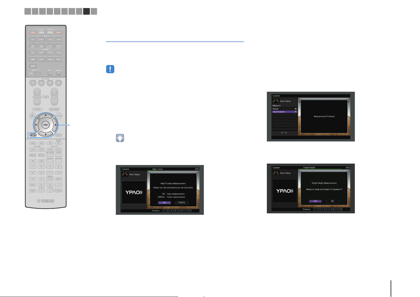
1 2 3 4 5 6 7 8 9 10
Cursor keys
ENTER
RETURN
Measuring at multiple listening positions (multi measure)
When “Multi Position” is set to “Yes”, follow the procedure below for
measurement. It takes about 15 minutes to measure 8 listening
positions.
• If any error message (such as E-1) or warning message (such as W-1) appears,
see “Error messages” (p.57) or “Warning messages” (p.58).
• (RX-A3040 only)
Do not use the microphone base until the corresponding message appear on the
TV.
To start the measurement, use the cursor keys to
1
select “Measure” and press ENTER.
The measurement will start in 10 seconds. Press ENTER
again to start the measurement immediately.
• To cancel the measurement temporarily, press RETURN.
The following screen appears on the TV when the
measurement at the first position finishes.
When the measurements at the positions you want
3
to measure are completed, use the cursor keys to
select “CANCEL” and press ENTER.
When you have taken measurements at 8 listening
positions, the following screen appears automatically.
(RX-A2040)
(RX-A3040 [when angle/height measurement is disabled])
Proceed to Step 5.
(RX-A3040 [when angle/height measurement is enabled])
Proceed to Step 4.
Move the YPAO microphone to the next listening
2
position and press ENTER.
Repeat Step 2 until measurements at all listening positions
(up to 8) have been taken.
PREPARATIONS ➤ Optimizing the speaker settings automatically (YPAO) En 53
Page 54
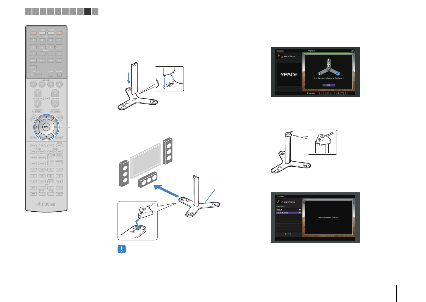
Microphone base
Pole
Microphone base
1 2 3 4 5 6 7 8 9 10
Cursor keys
ENTER
Perform the angle/height measurement.
4
a Use the cursor keys to select “YES” and press ENTER.
Select “NO” to cancel the angle/height measurement.
b Attach the supplied pole to the center of the microphone base.
c Place the microphone base at the listening position you will be
seated most frequently and set the YPAO microphone to the
position “1”.
d Press ENTER to start the first angle measurement.
The following screen appears on the TV when the first angle
measurement finishes.
e In the same way, perform the angle measurement for the
positions “2” and “3”.
f Set the YPAO microphone at the top of the pole and perform the
fourth angle measurement.
The following screen appears on the TV when the fourth angle
measurement finishes.
• We recommend using a tripod to place the microphone base at ear height.
Use the tripod screws to fix the microphone base in place.
• Do not move the microphone base until the fourth angle measurement
finishes.
PREPARATIONS ➤ Optimizing the speaker settings automatically (YPAO) En 54
Page 55

1 2 3 4 5 6 7 8 9 10
Cursor keys
ENTER
Use the cursor keys to select “Save/Cancel” and
5
press ENTER.
• To check the measurement results, select “Result”. For details, see
“Checking the measurement results” (p.55).
To save the measurement result, use the cursor
6
keys to select “SAVE” and press ENTER.
The adjusted speaker settings are applied.
• To finish the measurement without saving the result, select “CANCEL”.
Use the cursor keys (e/r) to select “YES” or “NO”
7
to enable/disable YPAO Volume and press ENTER.
Disconnect the YPAO microphone from the unit.
8
This completes optimization of the speaker settings.
Caution
• The YPAO microphone is sensitive to heat, so should not be placed anywhere
where it could be exposed to direct sunlight or high temperatures (such as on
top of AV equipment).
Checking the measurement results
You can check the YPAO measurement results.
After the measurement, use the cursor keys to
1
select “Result” and press ENTER.
• You can also select “Result” from “Auto Setup” (p.121) in the “Setup” menu,
which displays the previous measurement results.
The following screen appears.
1
2
• If YPAO Volume is enabled, the high- and low-frequency levels are
automatically adjusted according to the volume so that you can enjoy
natural sounds even at low volume.
• You can also enable/disable YPAO Volume in “YPAO Volume” (p.108) in the
“Option” menu.
PREPARATIONS ➤ Optimizing the speaker settings automatically (YPAO) En 55
3
1 Measurement result items
2 Measurement result details
3 The number of measured positions (when multi
measure is performed)
Page 56

1 2 3 4 5 6 7 8 9 10
ON SCREEN
Cursor keys
ENTER
RETURN
Use the cursor keys to select an item.
2
Wiring
Size
Distance Distance from the listening position to each speaker
Level Output level adjustment for each speaker
Angle
(Horizontal)
Height
To finish checking the results and return to the
3
Polarity of each speaker
Reverse: The speaker cable may be connected with the
reverse polarity (+/-).
Size of each speaker (cross-over frequency of the
subwoofer)
Large: The speaker can reproduce low-frequency
signals effectively.
Small: The speaker cannot reproduce low-frequency
signals effectively.
(RX-A3040 only)
Horizontal angle of each speaker at the listening
position
(RX-A3040 only)
Height of the presence speakers above the level of the
listening position
previous screen, press RETURN.
Reloading the previous YPAO adjustments
When the speaker settings you have configured manually are not
suitable, follow the procedure below to discard the manual settings
and reload the previous YPAO adjustments.
In the “Setup” menu, select “Speaker”, “Auto
1
Setup”, and then “Result” (p.120).
Use the cursor keys to select “Setup Reload‘” and
2
press ENTER.
To exit from the menu, press ON SCREEN.
3
PREPARATIONS ➤ Optimizing the speaker settings automatically (YPAO) En 56
Page 57

1 2 3 4 5 6 7 8 9 10
Error messages
If any error message is displayed during the measurement, resolve the problem and perform YPAO again.
Error message Cause Remedy
E-1: No Front SP Front speakers are not detected.
Follow the on-screen instructions to exit YPAO, turn off the unit, and then check the speaker connections.E-2: No Sur. SP One of the surround speakers cannot be detected.
E-3: No F.PRNS SP One of the front presence speakers cannot be detected.
E-4: SBR → SBL A surround back speaker is connected to the R side only.
E-5: Noisy The noise is too loud.
E-6: Check Sur.
E-7: No MIC The YPAO microphone has been removed.
E-8: No Signal The YPAO microphone cannot detect test tones.
E-9: User Cancel The measurement has been canceled. Follow the on-screen instructions to start the measurement again. To cancel the measurement, select “EXIT”.
E-10: Internal Error An internal error has occurred.
E-11: No R.PRNS SP One of the rear presence speakers cannot be detected. Follow the on-screen instructions to exit YPAO, turn off the unit, and then check the speaker connections.
Surround back speakers are connected, but no surround
speakers are connected.
When using only one surround back speaker, you need to connect it to the SINGLE jack (L side). Follow the
on-screen instructions to exit YPAO, turn off the unit, and then reconnect the speaker.
Keep the room quiet and follow the on-screen instructions to start the measurement again. If you select
“PROCEED”, YPAO takes the measurement again and ignores any noise detected.
Surround speakers need to be connected in order to use surround back speakers. Follow the on-screen
instructions to exit YPAO, turn off the unit, and then reconnect the speakers.
Connect the YPAO microphone to the YPAO MIC jack firmly and follow the on-screen instructions to start the
measurement again.
Connect the YPAO microphone to the YPAO MIC jack firmly and follow the on-screen instructions to start the
measurement again. If this error occurs repeatedly, contact the nearest authorized Yamaha dealer or service
center.
Follow the on-screen instructions to exit YPAO, turn off and on the unit. If this error occurs repeatedly, contact
the nearest authorized Yamaha dealer or service center.
PREPARATIONS ➤ Optimizing the speaker settings automatically (YPAO) En 57
Page 58

1 2 3 4 5 6 7 8 9 10
Warning messages
If a warning message is displayed after the measurement, you can still save the measurement results by following on-screen instructions.
However, we recommend you perform YPAO again in order to use the unit with the optimal speaker settings.
Warning message Cause Remedy
Select “Wiring” in “Result” (p.56) and check the cable connections (+/-) of the speaker identified by
“Reverse”.
W-1: Out of Phase
W-2: Over Distance
W-3: Level Error
A speaker cable may be connected with the reverse polarity
(+/-).
A speaker is placed more than 24 m (80 ft) from the listening
position.
There are significant volume differences between the
speakers.
If the speaker is connected incorrectly:
Turn off the unit and then reconnect the speaker cable.
If the speaker is connected correctly:
Depending on the type of speakers or room environment, this message may appear even if the speakers are
connected correctly. In this case, you can ignore the message.
Select “Distance” in “Result” (p.55) and move the speaker identified by “>24.00m (>80.0ft)” within 24 m
(80 ft) of the listening position.
Select “Level” in “Result” (p.56) and check the speaker identified by “Over ±10.0dB”, then check the usage
environment and cable connections (+/-) of each speaker, and the volume of the subwoofer. We recommend
using the same speakers or speakers with specifications that are as similar as possible.
PREPARATIONS ➤ Optimizing the speaker settings automatically (YPAO) En 58
Page 59

The unit
Wireless router
Mobile device
(such as iPhone)
Internet
Modem
The unit
Mobile device
(such as iPhone)
1 2 3 4 5 6 7 8 9 10
10 Connecting to a network device wirelessly
Connect the unit to a wireless router (access point) or a mobile device by establishing a
wireless connection.
Selecting the connection method
Select a connection method according to your network environment.
■ Connecting with a wireless router (access point)
Connect the unit to a wireless router (access point).
You can enjoy Internet radio, AirPlay, or music files stored on media servers (PC/NAS)
on the unit.
For details on connection, see “Connecting the unit to a wireless network” (p.60).
■ Connecting without a wireless router (access point)
Connect a mobile device to the unit directly.
You can use the application for smartphone / tablet “AV CONTROLLER” to control the
unit from mobiles devices or enjoy music files stored on mobiles devices on the unit.
For details on connection, see “Connecting a mobile device to the unit directly
(Wireless Direct)” (p.65).
• You cannot use Wireless Direct simultaneously with the wired (network cable) connection (p.43) or the
wireless network connection (p.60).
• When Wireless Direct is enabled, the following functions are not available.
– Internet radio
–Network services
– Playback of music stored on media servers (PC/NAS)
• For details on “AV CONTROLLER”, visit the Yamaha website.
• You cannot use the wireless network connection simultaneously with the wired (network cable) connection
(p.43) or Wireless Direct (p.65).
• If the unit and the wireless router (access point) are too far apart, the unit may not connect to a wireless
router (access point). In such case, place them close to each other.
PREPARATIONS ➤ Connecting to a network device wirelessly En 59
Page 60

Yes
Do you own iOS devices
(iPhone/iPad/iPod touch)?
Yes
A (p.60)
B (p.61)
Does your wireless router
(access point) has a WPS
button?
C (p.62)
No
No
1 2 3 4 5 6 7 8 9 10
RECEIVER z
ON SCREEN
Cursor keys
ENTER
Connecting the unit to a wireless network
There are several methods to connect the unit to a wireless
network.
Select a connection method according to your environment.
■ A: Sharing the iOS device setting
You can easily setup a wireless connection by applying the
connection settings on iOS devices (iPhone/iPad/iPod touch).
Before proceeding, confirm that your iOS device is connected to a
wireless router.
• You need iOS device with iOS 5.0 or later. For details on supported devices, see
“Supported devices and file formats” (p.165).
Use the cursor keys to select “Setup” and press
4
ENTER.
Use the cursor keys (e/r) to select “Network”.
5
Use the cursor keys (q/w) to select “Network
6
Connection” and press ENTER.
Use the cursor keys (q/w) and ENTER to check
7
“Wireless (Wi-Fi)” and select “OK”.
• The checkmark indicates the current setting.
Use the cursor keys (q/w) and ENTER to check
8
“Share Wi-Fi Settings (iOS)” and select “NEXT”.
Press RECEIVER z to turn on the unit.
1
Turn on the TV and switch the TV input to display
2
video from the unit (HDMI OUT jack).
• Operations with TV screen are available only when your TV is connected to
the unit via HDMI.
Press ON SCREEN.
3
PREPARATIONS ➤ Connecting to a network device wirelessly En 60
Page 61
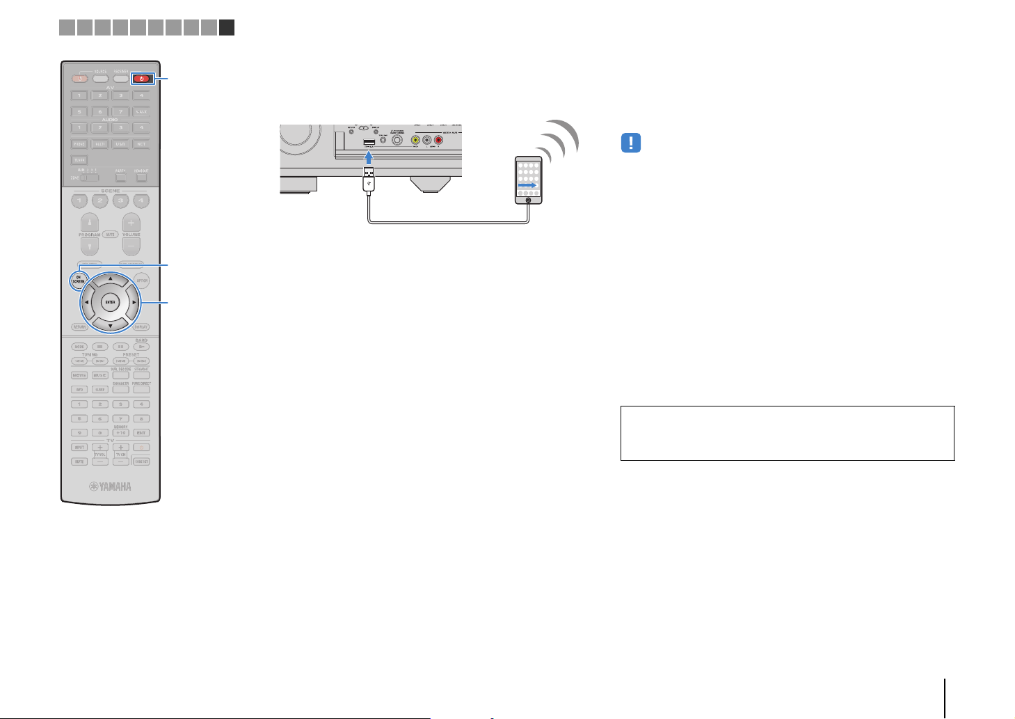
The unit (front)
1 2 3 4 5 6 7 8 9 10
RECEIVER z
ON SCREEN
Cursor keys
ENTER
Connect the iOS device to the USB jack, and disable
9
the screen lock on the iOS device.
Use the cursor keys (e/r) to select “NEXT” and
10
press ENTER.
Tap “Allow” in the message appeared on the iOS
11
device.
When the connection process finishes, “Completed”
appears on the TV screen.
To exit from the menu, press ON SCREEN.
12
■ B: Using the WPS push button
configuration
You can easily set up a wireless connection with one push of the
WPS button.
• This configuration does not work if the security method of your wireless router
(access point) is WEP. In this case, use other connection method.
Press RECEIVER z to turn on the unit.
1
Hold down INFO (WPS) on the front panel for 3
2
seconds.
“Press WPS button on Access Point” appears on the front
display.
Push the WPS button on the wireless router (access
3
point).
When the connection process finishes, “Completed”
appears on the front display.
If “Not connected” appears, repeat from Step 1 or try
another connection method.
About WPS
WPS (Wi-Fi Protected Setup) is a standard established by the Wi-Fi Alliance,
which allows easy establishment of a wireless home network.
PREPARATIONS ➤ Connecting to a network device wirelessly En 61
Page 62
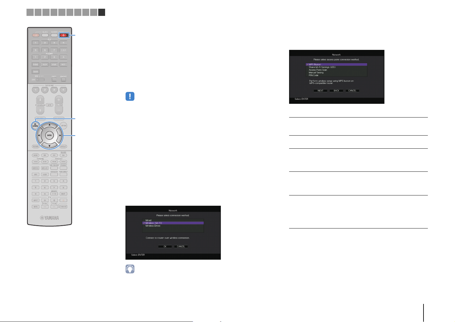
1 2 3 4 5 6 7 8 9 10
RECEIVER z
ON SCREEN
Cursor keys
ENTER
■ C: Using other connection methods
If your wireless router (access point) does not support WPS push
button configuration method, follow the procedure below to
configure the wireless network settings.
Press RECEIVER z to turn on the unit.
1
Turn on the TV and switch the TV input to display
2
video from the unit (HDMI OUT jack).
• Operations with TV screen are available only when your TV is connected to
the unit via HDMI.
Press ON SCREEN.
3
Use the cursor keys to select “Setup” and press
4
ENTER.
Use the cursor keys (e/r) to select “Network”.
5
Use the cursor keys (q/w) to select “Network
6
Connection” and press ENTER.
Use the cursor keys (q/w) and ENTER to check
7
“Wireless (Wi-Fi)” and select “OK”.
Use the cursor keys (q/w) and ENTER to select the
8
desired connection method and select “NEXT”.
The following connection methods are available.
WPS Button
Share Wi-Fi
Settings (iOS)
Access Point
Scan
Manual Setting
PIN Code
You can set up a wireless connection with the
WPS button while viewing the TV screen. Follow
the instructions displayed on the TV screen.
See “Sharing the iOS device setting” (p.60).
You can set up a wireless connection by
searching for an access point. For details on
settings, see “Searching for an access point”
(p.63).
You can setup a wireless connection by entering
the required information (such as SSID)
manually. For details on settings, see “Setting up
the wireless connection manually” (p.63).
You can set up a wireless connection by entering
the unit’s PIN code into the wireless router
(access point). The method is available if the
wireless router (access point) supports the WPS
PIN code method. For details on settings, see
“Using the PIN code” (p.64).
• The checkmark indicates the current setting.
PREPARATIONS ➤ Connecting to a network device wirelessly En 62
Page 63
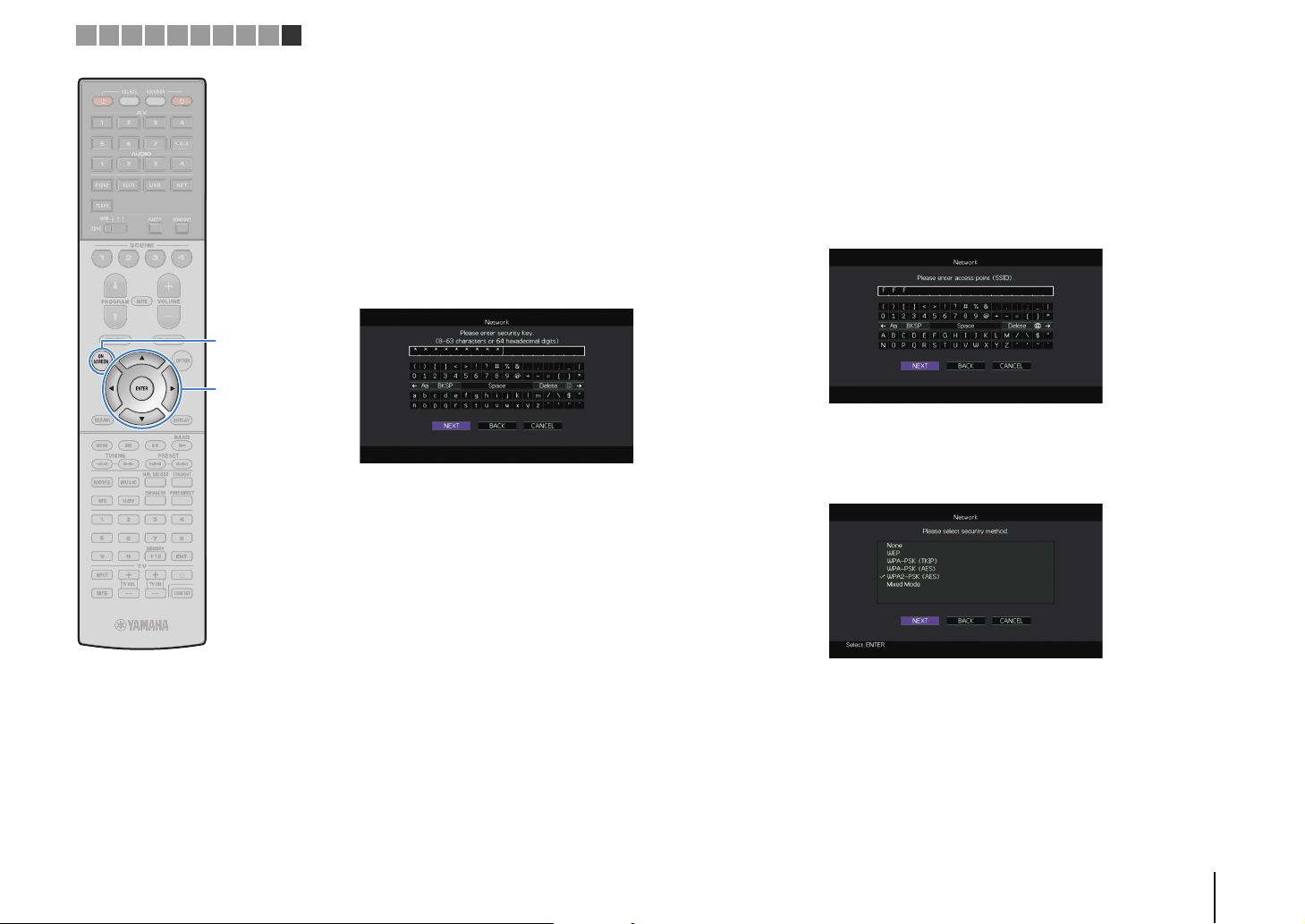
1 2 3 4 5 6 7 8 9 10
ON SCREEN
Cursor keys
ENTER
❑ Searching for an access point
If you select “Access Point Scan” as the connection method, the
unit starts searching for access points. After a while, the list of
available access points appears on the TV screen.
Use the cursor keys and ENTER to check the
1
desired access point and select “NEXT”.
The wireless connection setting screen appears on the TV.
Use the cursor keys and ENTER to enter the
2
security key and select “NEXT”.
Use the cursor keys (e/r) to select “CONNECT”
3
and press ENTER to start the connection process.
When the connection process finishes, “Completed”
appears on the TV screen.
If “Not connected” appears, repeat from Step 1 or try
another connection method.
❑ Setting up the wireless connection manually
If you select “Manual Setting” as the connection method, the
wireless connection setting screen appears on the TV.
You need to setup the SSID (network name), encryption method
and security key for your network.
Use the cursor keys and ENTER to enter the SSID of
1
the access point and select “NEXT”.
Use the cursor keys (q/w) and ENTER to check the
2
security method of the access point and select
“NEXT”.
To exit from the menu, press ON SCREEN.
4
Settings
None, WEP, WPA-PSK (TKIP), WPA-PSK (AES), WPA2-PSK (AES),
Mixed Mode
PREPARATIONS ➤ Connecting to a network device wirelessly En 63
Page 64
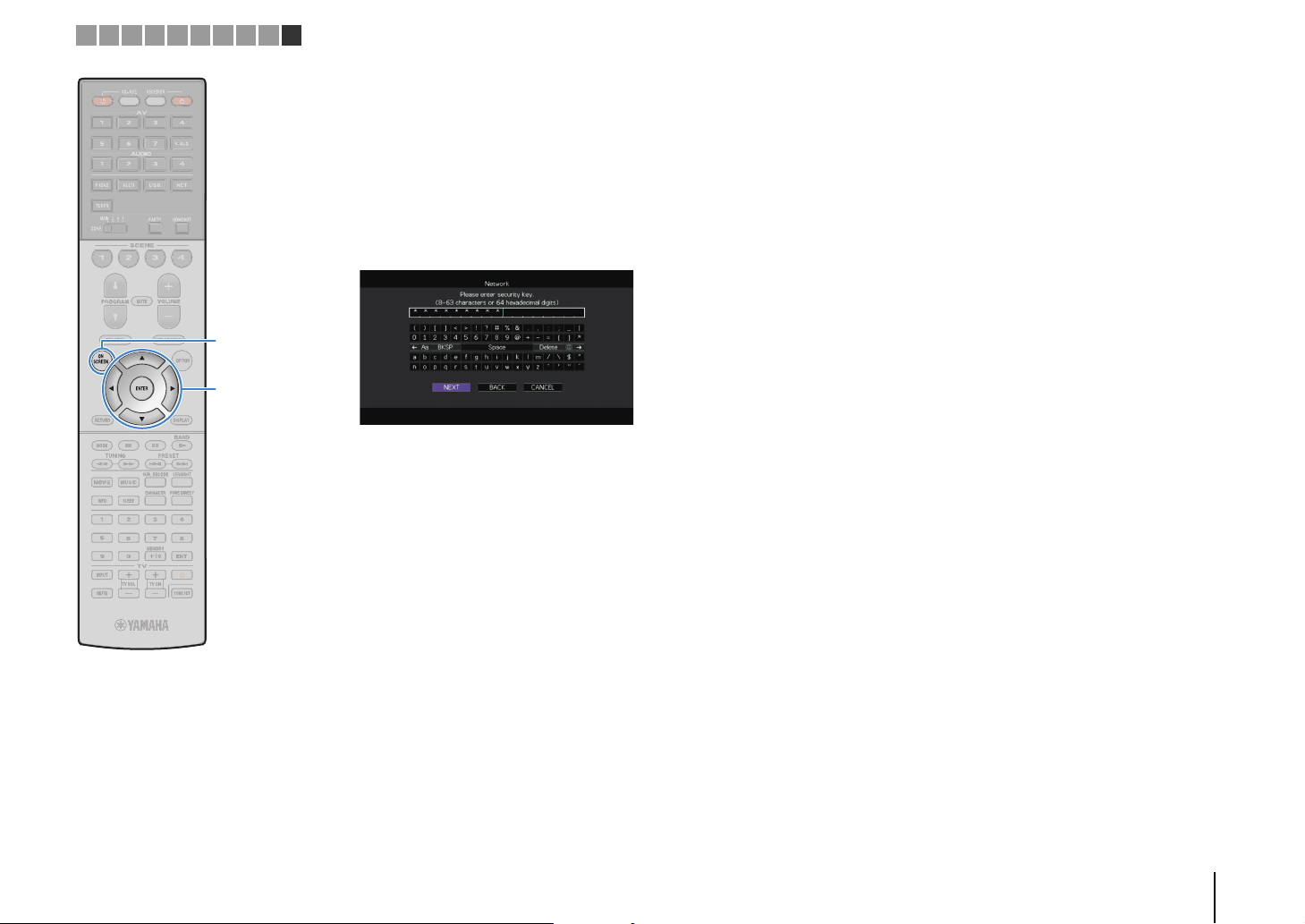
1 2 3 4 5 6 7 8 9 10
ON SCREEN
Cursor keys
ENTER
Use the cursor keys and ENTER to enter the
3
security key and select “NEXT”.
If you select “None” in Step 2, this setting is not available.
Proceed to Step 4.
If you select “WEP”, enter either 5 or 13 character string, or
10 or 26 hexadecimal digits.
If you select other method, enter either 8 to 63 character
string, or 64 hexadecimal digits.
Use the cursor keys (e/r) to select “CONNECT”
4
and press ENTER to start the connection process.
When the connection process finishes, “Completed”
appears on the TV screen.
If “Not connected” appears, check that all the information is
entered correctly, and repeat from Step 1.
❑ Using the PIN code
If you select “PIN Code” as the connection method, the list of
available access points appears on the TV screen.
Use the cursor keys and ENTER to check the
1
desired access point and select “NEXT”.
The PIN code of the unit appears on the TV screen.
Enter the unit’s PIN code into the wireless router
2
(access point).
For details on settings, refer to the instruction manual of the
wireless router (access point).
Use the cursor keys (e/r) to select “CONNECT”
3
and press ENTER to start the connection process.
When the connection process finishes, “Completed”
appears on the TV screen.
If “Not connected” appears, repeat from Step 1 or try
another connection method.
To exit from the menu, press ON SCREEN.
4
To exit from the menu, press ON SCREEN.
5
PREPARATIONS ➤ Connecting to a network device wirelessly En 64
Page 65
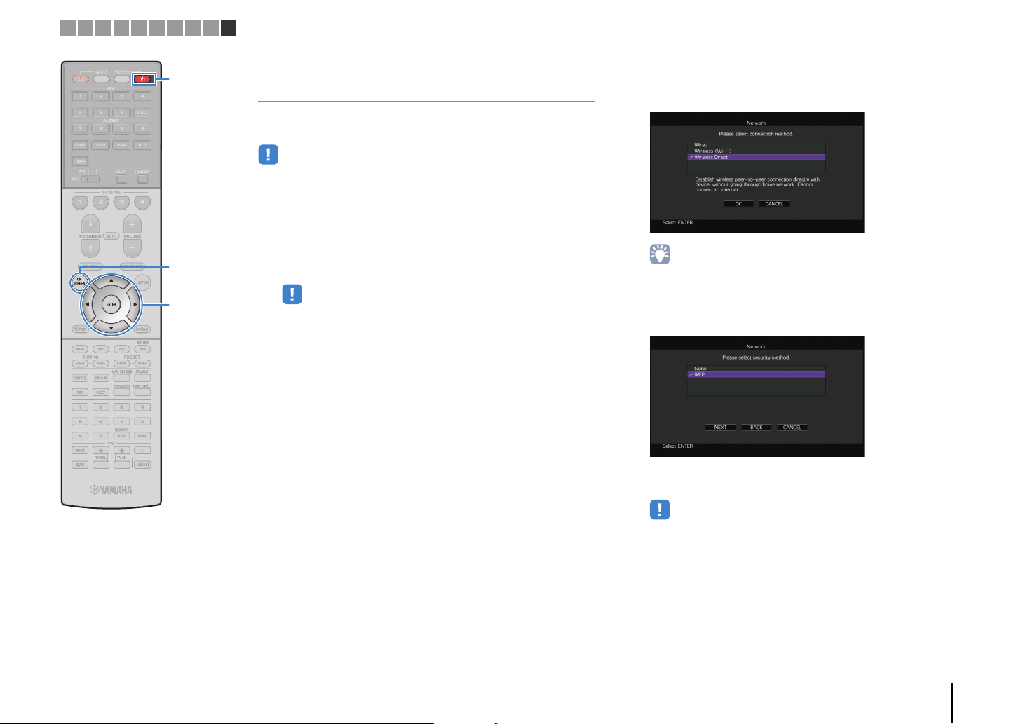
1 2 3 4 5 6 7 8 9 10
RECEIVER z
ON SCREEN
Cursor keys
ENTER
Connecting a mobile device to the unit directly (Wireless Direct)
Follow the procedure below to connect a mobile device to the unit
directly.
• Wireless Direct connection may be insecure since the communication is not
strongly encrypted. The unit may operate by playback operation on wireless
devices connected to the unit without permission.
Press RECEIVER z to turn on the unit.
1
Turn on the TV and switch the TV input to display
2
video from the unit (HDMI OUT jack).
• Operations with TV screen are available only when your TV is connected to
the unit via HDMI.
Press ON SCREEN.
3
Use the cursor keys to select “Setup” and press
4
ENTER.
Use the cursor keys (e/r) to select “Network”.
5
Use the cursor keys (q/w) to select “Network
6
Connection” and press ENTER.
Use the cursor keys (q/w) and ENTER to check
7
“Wireless Direct” and select “OK”.
• The checkmark indicates the current setting.
Use the cursor keys (q/w) and ENTER to check the
8
desired security method and select “NEXT”.
Settings
None, WEP
• If you select “None”, the connection may be insecure since the
communication is not encrypted.
PREPARATIONS ➤ Connecting to a network device wirelessly En 65
Page 66

1 2 3 4 5 6 7 8 9 10
ON SCREEN
Cursor keys
ENTER
Use the cursor keys and ENTER to enter the
9
security key and select “NEXT”.
If you select “None” in Step 8, this setting is not available.
Proceed to Step 10.
Otherwise, enter either 5 or 13 character string.
Use the cursor keys (e/r) to select “OK” and press
10
ENTER to save the setting.
The settings made appear on the TV screen.
Configure the Wi-Fi settings of a mobile device.
11
For details on settings of your mobile device, refer to the
instruction manual of the mobile device.
a Enable the Wi-Fi function on the mobile device.
b Select the SSID displayed in Step 10 from the list of available
access points.
c When you are prompted for a password, enter the security key
displayed in Step 10.
To exit from the menu, press ON SCREEN.
12
The SSID and security key information is required for setup
of a mobile device.
PREPARATIONS ➤ Connecting to a network device wirelessly En 66
Page 67
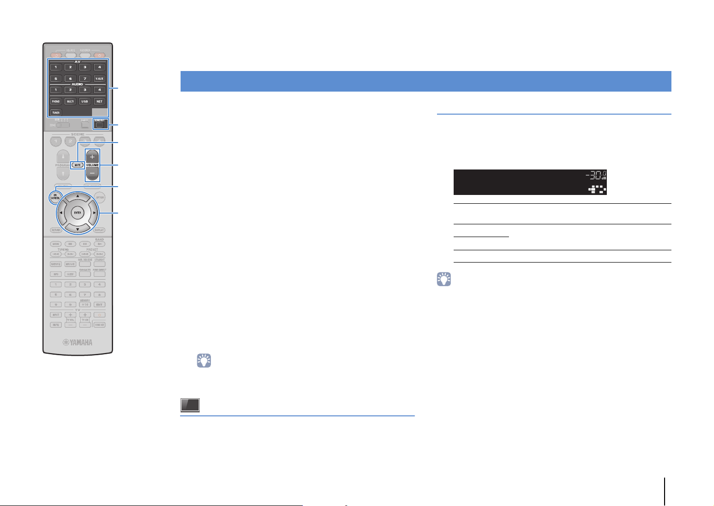
PLAYBACK
Input selection keys
HDMI OUT
MUTE
VOLUME
ON SCREEN
Cursor keys
ENTER
Basic playback procedure
Turn on the external devices (such as a TV or
1
BD/DVD player) connected to the unit.
Use the input selection keys to select an input
2
source.
Start playback on the external device or select a
3
radio station.
Refer to the instruction manual for the external device.
For details on the following operations, see the
corresponding pages.
• Listening to FM/AM radio (p.76)
• Playing back iPod music (p.83)
• Playing back music stored on a USB storage device
(p.86)
• Playing back music stored on media servers (PCs/NAS)
(p.89)
• Listening to Internet radio (p.92)
• Playing back music with AirPlay (p.95)
Press VOLUME to adjust the volume.
4
Selecting an HDMI output jack
Press HDMI OUT to select an HDMI OUT jack.
1
Each time you press the key, the HDMI OUT jack to be
used for signal output changes.
DOCK
TAG
HD
STEREO
OUT 1INOUT 2
ENHANCER
OUT 1+2
OUT 1
OUT 2
Off Does not output the signals at the HDMI OUT jacks.
• You can also select an HDMI output jack by selecting a scene (p.68).
• When “OUT 1+2” is selected, the unit outputs video signals at the highest
resolution supported by both TVs (or projectors) connected to the unit. (For
example, if you have connected a 1080p TV to the HDMI OUT 1 jack and a 720p
TV to the HDMI OUT 2 jack, the unit outputs 720p video signals.)
• If the HDMI OUT 2 jack is assigned to Zone2 or Zone4 (p.138), you can turn on/off
each zone by pressing HDMI OUT repeatedly.
HDMIOUTSel.
TUNED
PRE
AMP
PARTY
ZONE
ZONE3ZONE
2
4
SLEEP
3
HD
OUT1+2
Outputs the same signal at both the HDMI OUT 1
and HDMI OUT 2 jacks.
Output the signals at the selected HDMI OUT jack.
MUTE
PL
SW1SLSW2SW
SBLPL SBRSB PR
VOLUME
CL R
DRCADAPTIVE
PR
SR
• To mute the audio output, press MUTE. Press MUTE again to unmute.
• To adjust the treble/bass settings, use the “Option” menu or
TONE/BALANCE on the front panel (p.108).
On-screen input selection
a Press ON SCREEN.
b Use the cursor keys to select “Input” and press ENTER.
c Use the cursor keys to select the desired input source and
press ENTER.
PLAYBACK ➤ Basic playback procedure En 67
Page 68
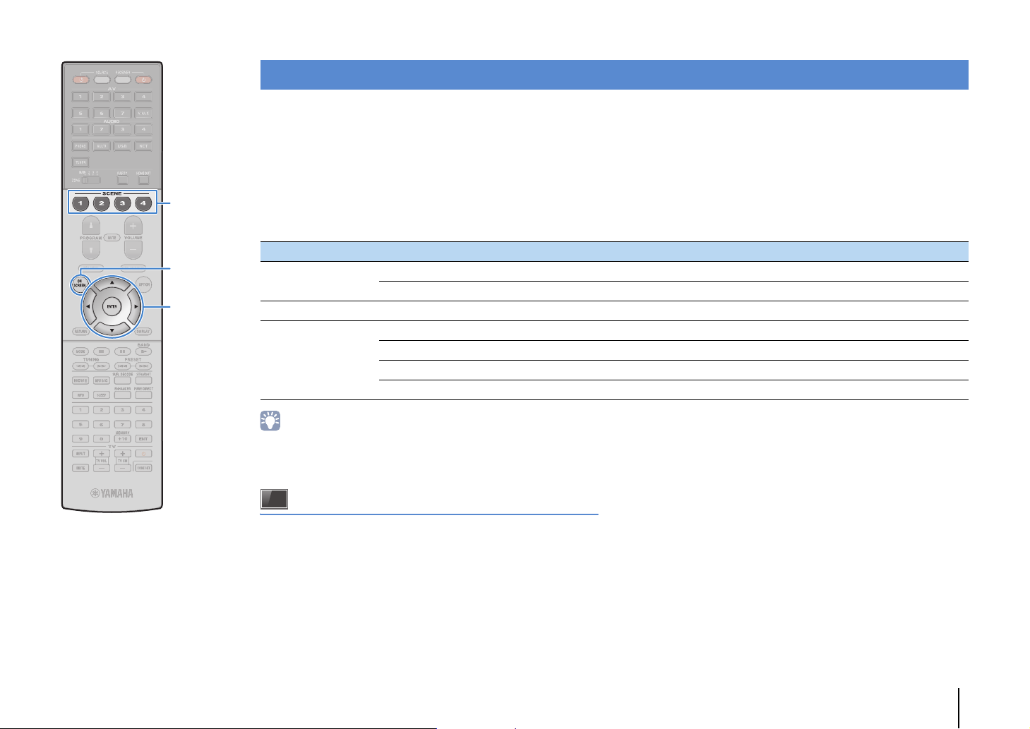
SCENE
ON SCREEN
Cursor keys
ENTER
Selecting the input source and favorite settings with one touch (SCENE)
The SCENE function allows you to select the assigned input source, sound program, HDMI output and various settings with just one touch.
You can use up to 12 scenes to register your favorite settings and switch them depending on a playback source.
Press SCENE.
1
The input source and settings registered to the
corresponding scene are selected. The unit turns on
automatically when it is in standby mode.
By default, the following settings are registered for each scene.
SCENE (SCENE key) 1 (BD/DVD) 2 (TV) 3 (NET) 4 (RADIO)
Input
HDMI Output HDMI Output (p.67) OUT 1+2 OUT 1+2 OUT 1+2 OUT 1+2
Mode
• You can select SCENE 1–4 by pressing SCENE on the remote control.
Additionally, you can create 8 scenes (SCENE 5–12) and select those scenes
from the “Scene” menu (p.114).
Input (p.67) AV 1 AUDIO 1 NET RADIO TUNER
Audio Select (p.110) Auto Auto — —
Sound Program (p.70) Sci-Fi STRAIGHT 9ch Stereo 9ch Stereo
Pure Direct Mode (p.130) Auto Auto Auto Auto
Enhancer (p.75) Off On On On
Enhancer Hi-Res Mode (p.109) On On On On
On-screen scene selection
a Press ON SCREEN.
b Use the cursor keys to select “Scene” and press ENTER.
c Use the cursor keys to select a desired scene and press
ENTER.
PLAYBACK ➤ Selecting the input source and favorite settings with one touch (SCENE) En 68
Page 69
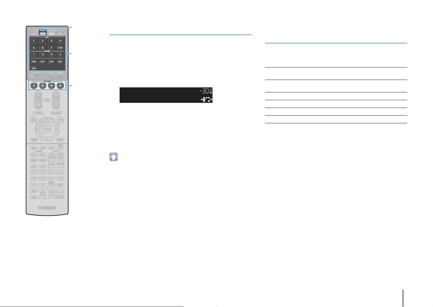
OUT 1INOUT 2
VOLUME
MUTE
DRCADAPTIVE
3
ZONE
2
SBLPL SBRSB PR
SW1SLSW2SW
SR
PL
CL R
PR
STEREO
ENHANCER
SLEEP
HD
TUNED
PRE
AMP
PARTY
ZONE3ZONE
4
HD
TAG
DOCK
SETComplete
SCENE1
SOURCE
Input selection keys
Configuring scene assignments
Set the unit to the condition (such as input source
1
and sound program) that you want to assign to a
scene.
Selecting setting items to be included as scene assignments
In addition to the default scene assignments (Input, HDMI Output
and Mode), you can also include the following setting items as the
scene assignments in “Detail” (p.115) in the “Scene” menu.
SCENE
Hold down the desired SCENE key until “SET
2
Complete” appears on the front display.
If you want to control the corresponding playback
3
device after selecting the scene, hold down the
corresponding SCENE key and input selection key
together for more than 3 seconds.
Once the setting is completed successfully, SOURCE blinks twice.
• If you have not registered the remote control code of the playback device yet, see
“Registering the remote control codes for playback devices” (p.149) to register it.
• The SCENE link playback function allows you to start playback of an external
device connected to the unit via HDMI. To enable SCENE link playback, specify
the device type in “Device Control” (p.115) in the “Scene” menu.
Sound
Surround
Tone Control, YPAO Volume, Adaptive DRC,
Extra Bass
CINEMA DSP 3D Mode, Dialogue Lift, Dialogue
Level, Subwoofer Trim, Extended Surround
Video Video Mode, Video Adjustment
Vol um e Master Volume
Lipsync Lipsync, Delay
Speaker Setup Setting Pattern, PEQ Select
PLAYBACK ➤ Selecting the input source and favorite settings with one touch (SCENE) En 69
Page 70

Selecting the sound mode
PROGRAM
ON SCREEN
Cursor keys
ENTER
MOVIE
MUSIC
SUR.DECODE
STRAIGHT
ENHANCER
PURE DIRECT
The unit is equipped with a variety of sound programs and
surround decoders that allow you to enjoy playback sources with
your favorite sound mode (such as sound field effect or stereo
playback).
❑ Selecting a sound program suitable for movies
• Press MOVIE repeatedly.
This mode lets you enjoy sound field effects optimized for viewing
video sources, such as movies, TV programs, and games (p.71).
❑ Selecting a sound program suitable for music or
stereo playback
• Press MUSIC repeatedly.
This mode lets you enjoy sound field effects optimized for listening
music sources or stereo playback (p.72).
❑ Selecting a surround decoder
• Press SUR.DECODE repeatedly.
This mode lets you enjoy unprocessed multichannel playback from
2-channel sources (p.74).
❑ Switching to the straight decode mode
• Press STRAIGHT.
This mode lets you enjoy unprocessed sounds in original channels
(p.74).
On-screen sound program/surround decoder selection
a Press ON SCREEN.
b Use the cursor keys to select “Sound Program” and press
ENTER.
c Use the cursor keys to select a sound program/surround
decoder and press ENTER.
• You can also switch the sound programs and surround decoder by pressing
PROGRAM.
• You can change the settings of the surround programs and surround decoders in
the “Sound Program” menu (p.116).
• The sound mode can be applied separately to each input source.
• You can check which speakers are currently outputting sound by looking at the
speaker indicators on the unit’s front panel (p.13) or at the “Audio Signal” screen in
the “Information” menu (p.142).
❑ Switching to the Pure Direct mode
• Press PURE DIRECT.
This mode lets you enjoy pure high fidelity sound by reducing the
electrical noise from other circuitry (p.75).
❑ Enabling Compressed Music Enhancer
• Press ENHANCER.
This mode lets you enjoy compressed music with additional depth
and breadth (p.75).
PLAYBACK ➤ Selecting the sound mode En 70
Page 71
Enjoying stereoscopic sound fields
“CINEMA DSP !” (RX-A3040) or “CINEMA DSP n” (RX-A2040) lights up
Sound program category
Sound program
(CINEMA DSP HD/CINEMA DSP 3D)
* CINEMA DSP HD³: RX-A3040, CINEMA DSP 3D: RX-A2040
The unit is equipped with a variety of sound programs that utilize Yamaha’s original DSP
technology (CINEMA DSP HD³/CINEMA DSP 3D). It allows you to easily create sound
fields like actual movie theaters or concert halls in your room and enjoy natural
stereoscopic sound fields.
DOCK
TAG
MUSIC
HD
STEREO
TUNED
OUT 1INOUT 2
ENHANCER
• To use the conventional CINEMA DSP, set “CINEMA DSP 3D Mode” (p.130) in the “Setup” menu to “Off”.
• The unit creates front Virtual Presence Speaker (VPS) using the front, center, and surround speakers to
produce 3-dimensional sound fields even when no front presence speakers are connected. However, we
recommend using front presence speakers in order to experience the full effect of the sound fields (and
rear presence speakers for further spatial sounds).
• When Vir tual Presence Speaker (VPS) is working, “VIRTUAL” lights up in the front display.
• (RX-A3040 only)
The unit creates rear Virtual Presence Speaker (VPS) using the front, center, and surround speakers to
produce natural 3-dimensional sound fields when front presence speakers are connected but no rear
presence speakers.
CLASSICAL
PRE
AMP
PARTY
ZONE
ZONE3ZONE
2
4
SLEEP
3
HD
HallinVienna
MUTE
PL
SW1SLSW2SW
SBLPL SBRSB PR
VOLUME
CL R
DRCADAPTIVE
PR
SR
■ Sound programs suitable for movies (MOVIE)
The following sound programs are optimized for viewing video sources, such as
movies, TV programs, and games.
❑ MOVIE THEATER
This program creates a sound field that emphasizes the surround feeling
Standard
Spectacle
Sci-Fi
Adventure
Drama
Mono Movie
without disturbing the original acoustic positioning of multichannel audio,
such as Dolby Digital and DTS. Its design is based on the concept of the
ideal movie theater, in which the audience is surrounded by beautiful
reverberations from the left, right, and rear.
This program delivers the scale and grandeur of spectacular movie
productions. It delivers an expansive sound space to match the
cinemascope wide-screen, and boasts a broad dynamic range, providing
everything from small delicate sounds to powerful loud booms.
This program clearly reproduces the finely elaborated sound design of the
latest Sci-Fi and SFX movies. You can enjoy a variety of
cinematographically created virtual spaces reproduced with clear
separation between dialogue, sound effects, and background music.
This program is ideal for reproducing the sound design of action and
adventure movies precisely. The sound field restrains reverberations, but
puts emphasis on reproducing a sensation of expansiveness on both sides,
powerful space expanded widely to the left and right. The restrained depth
creates a clear and powerful space, while also maintaining the articulation
of the sounds and the separation of the channels.
This program features stable reverberations that match a wide range of
movie genres, from serious dramas to musicals and comedies. The
reverberations are modest, but suitably stereophonic. The sound effects
and background music are reproduced with a gentle echo that does not
impinge on the articulation of the dialogue. You’ll never get tired listening for
long periods.
This program reproduces monaural video sources, such as classic movies,
in an atmosphere of a good old movie theater. The program creates a
pleasant space with depth, by adding breadth and the appropriate
reverberation to the original audio.
PLAYBACK ➤ Selecting the sound mode En 71
Page 72

❑ ENTERTAINMENT
This program allows listeners to enjoy the rich vividness of sport broadcasts
Sports
Action Game
Roleplaying Game
Music Video
Recital/Opera
and light entertainment programs. In sports broadcasts, the commentators’
voices are positioned clearly at the center, while the atmosphere inside the
stadium is realistically conveyed by the peripheral delivery of the sounds of
the fans in a suitable space.
This program is suitable for action games, such as car racing and fighting
games. The reality of, and emphasis on, various effects makes the player
feel like they are right in the middle of the action, allowing for greater
concentration. Use this program in combination with Compressed Music
Enhancer for a more dynamic and strong sound field.
This program is suitable for role-playing and adventure games. This
program adds depth to the sound field for natural and realistic reproduction
of background music, special effects, and dialogue from a wide variety of
scenes. Use this program in combination with Compressed Music
Enhancer for a clearer and more spatial sound field.
This program allows you to enjoy videos of pop, rock, and jazz concerts, as
if you were there yourself. Immerse yourself in the hot concert atmosphere
thanks to the vividness of the singers and solos on stage, a presence
sound field that emphasizes the beat of rhythm instruments, and a surround
sound field that reproduces the space of a big live hall.
This program controls the amount of reverberations at an optimum level and
emphasizes the depth and clarity of human voices to offer the
reverberations of an orchestra box in front the listener at the same time as
providing the acoustic positioning and feeling of presence on the stage.
The surround sound field is relatively moderate, but the data for concert hall
effects are used to represent the inherent beauty of music. The listener will
not be fatigued even after long hours of opera entertainment.
■ Sound programs suitable for music/stereo playback
(MUSIC)
The following sound programs are optimized for listening to music sources.
You can also select stereo playback.
❑ CLASSICAL
This program simulates a Munich concert hall with approximately 2,500
Hall in Munich
Hall in Vienna
Hall in Amsterdam
Church in Freiburg
Church in
Royaumont
Chamber
seats that uses stylish wood for the interior finishing. Fine, beautiful
reverberations spread richly, creating a calming atmosphere. The listener’s
virtual seat is at the center left of the arena.
This program simulates a 1,700-seat, middle-sized concert hall with a
shoebox shape that is traditional in Vienna. Pillars and ornate carvings
create extremely complex reverberations from all around the audience,
producing a very full, rich sound.
The large, shoe box shaped hall seats about 2,200 around the circle stage.
Reflections are rich and pleasing while the sound travels freely.
Located in the south of Germany, this grand, stone-built church has a
pointed tower at 120 meters in height. Its long and narrow shape and the
high ceiling enable the elongated reverberation time and limited initial
reflection time. Thus, the rich reverberation rather than the sound itself
reproduces the atmosphere of the church.
This program features the sound field created by the refectory (dining hall)
of a beautiful medieval Gothic monastery located in Royaumont on the
outskirts of Paris.
This program creates a relatively wide space with a high ceiling, like an
audience hall in a palace. It offers pleasant reverberations that are suitable
for courtly music and chamber music.
PLAYBACK ➤ Selecting the sound mode En 72
Page 73

❑ LIVE/CLUB
Village Vanguard
Warehouse Loft
Cellar Club
The Roxy Theatre
The Bottom Line
The Jazz club is on 7th Avenue, New York. This small club with the low
ceiling makes the powerful reflections converge toward the stage located in
the center.
The warehouse resembles some lofts in Soho. Sound reflects off the
concrete walls clearly with a lot of energy.
This program simulates an intimate concert venue with a low ceiling and
homey atmosphere. A realistic, live sound field delivers powerful sounds
that make you feel as if you are sitting in the front row in front of a small
stage.
This program creates the sound field of a 460-seat rock music concert
venue in Los Angeles. The listener’s virtual seat is at the center left of the
hall.
This program creates the sound field at stage front in The Bottom Line, a
famous New York jazz club once. The floor can seat 300 people to the left
and right in a sound field offering real and vibrant sound.
❑ STEREO
2ch Stereo
9ch Stereo
• CINEMA DSP HD³/CINEMA DSP 3D (p.71) and Virtual CINEMA DSP (p.73) do not work when “2ch
Stereo” or “9ch Stereo” is selected.
Use this program to mix down multichannel sources to 2 channels. When
multichannel signals are input, they are down mixed to 2 channels and
output from the front speakers (this program does not utilize CINEMA DSP).
Use this program to output sound from all speakers. When you play back
multichannel sources, the unit mixes down the source to 2 channels, and
then outputs the sound from all speakers. This program creates a larger
sound field and is ideal for background music at parties.
■ Enjoying sound field effects without surround speakers
(Virtual CINEMA DSP)
If you select one of the sound programs (except 2ch Stereo and 9ch Stereo) when no
surround speakers are connected, the unit utilizes Yamaha’s original virtual surround
technology to reproduce up to 7-channel surround sound and enable you to enjoy the
well-oriented sound field only with the front-side speakers. We recommend using
presence speakers in order to enjoy more effective stereoscopic sound field.
• When Virtual CINEMA DSP is working, “VIRTUAL” lights up in the front display.
■ Enjoying surround sound with 5 speakers placed in front
(Virtual CINEMA FRONT)
If you have surround speakers but there is no space to place them in the rear of your
room, you can place them in the front (p.21) and enjoy multi-channel surround sound
using Virtual CINEMA FRONT.
When “Layout (Surround)” (p.126) in the “Setup” menu is set to “Front”, the unit creates
the virtual surround speakers in the rear side to allow you to enjoy multi-channel
surround sound with the 5 speakers placed in the front.
• When Virtual CINEMA FRONT is working, “VIRTUAL” lights up in the front display.
■ Enjoying surround sound with headphones
(SILENT CINEMA)
You can enjoy surround or sound field effects, like a multichannel speaker system, with
stereo headphones by connecting the headphones to the PHONES jack and selecting
a sound program or a surround decoder.
PLAYBACK ➤ Selecting the sound mode En 73
Page 74

VOLUME
SBL SBR
SW1
SL SR
CL R
STRAIGHT
SUR.DECODE
STRAIGHT
Enjoying unprocessed playback
You can play back input sources without any sound field effect
processing.
■ Playing back in original channels
(straight decode)
When the straight decode mode is enabled, the unit produces
stereo sound from the front speakers for 2-channel sources such as
CDs, and produces unprocessed multichannel sounds for
multichannel sources.
Press STRAIGHT.
1
Each time you press the key, the straight decode mode is
enabled or disabled.
• To enable 6.1/7.1-channel playback from 5.1-channel sources when surround
back speakers are used, set “Extended Surround” (p.130) in the “Setup” menu to
a setting other than “Off”.
• If “Layout (Surround)” (p.126) in the “Setup” menu is set to “Front”, Virtual
CINEMA FRONT (p.73) works when multi-channel source is played back.
■ Playing back 2-channel sources in
multichannel (surround decoder)
The surround decoder enables unprocessed multichannel
playback from 2-channel sources. When a multichannel source is
input, it works the same way as the straight decode mode.
For details on each decoder see “Glossary” (p.162).
Press SUR.DECODE to select a surround decoder.
1
Each time you press the key, the surround decoder
changes.
DOCK
TAG
HD
STEREO
OUT 1INOUT 2
ENHANCER
bPro Logic
bPLIIx Movie
bPLII Movie
bPLIIx Music
bPLII Music
bPLIIx Game
bPLII Game
Neo:6 Cinema Uses the DTS Neo:6 decoder suitable for movies.
Neo:6 Music Uses the DTS Neo:6 decoder suitable for music.
SUR.DECODE
TUNED
PRE
AMP
PARTY
ZONE
ZONE3ZONE
2
4
SLEEP
3
HD
ProLogic
Uses the Dolby Pro Logic decoder suitable for all
sources.
Use the Dolby Pro Logic IIx decoder (or Dolby Pro
Logic II decoder) suitable for movies.
Use the Dolby Pro Logic IIx decoder (or Dolby Pro
Logic II decoder) suitable for music.
Use the Dolby Pro Logic IIx decoder (or Dolby Pro
Logic II decoder) suitable for games.
MUTE
PL
SW1SLSW2SW
SBLPL SBRSBPR
VOLUME
CL R
DRCADAPTIVE
PR
SR
• You cannot select the Dolby Pro Logic IIx decoders when headphones are
connected or when “Surround Back” (p.125) in the “Setup” menu is set to
“None”.
PLAYBACK ➤ Selecting the sound mode En 74
Page 75
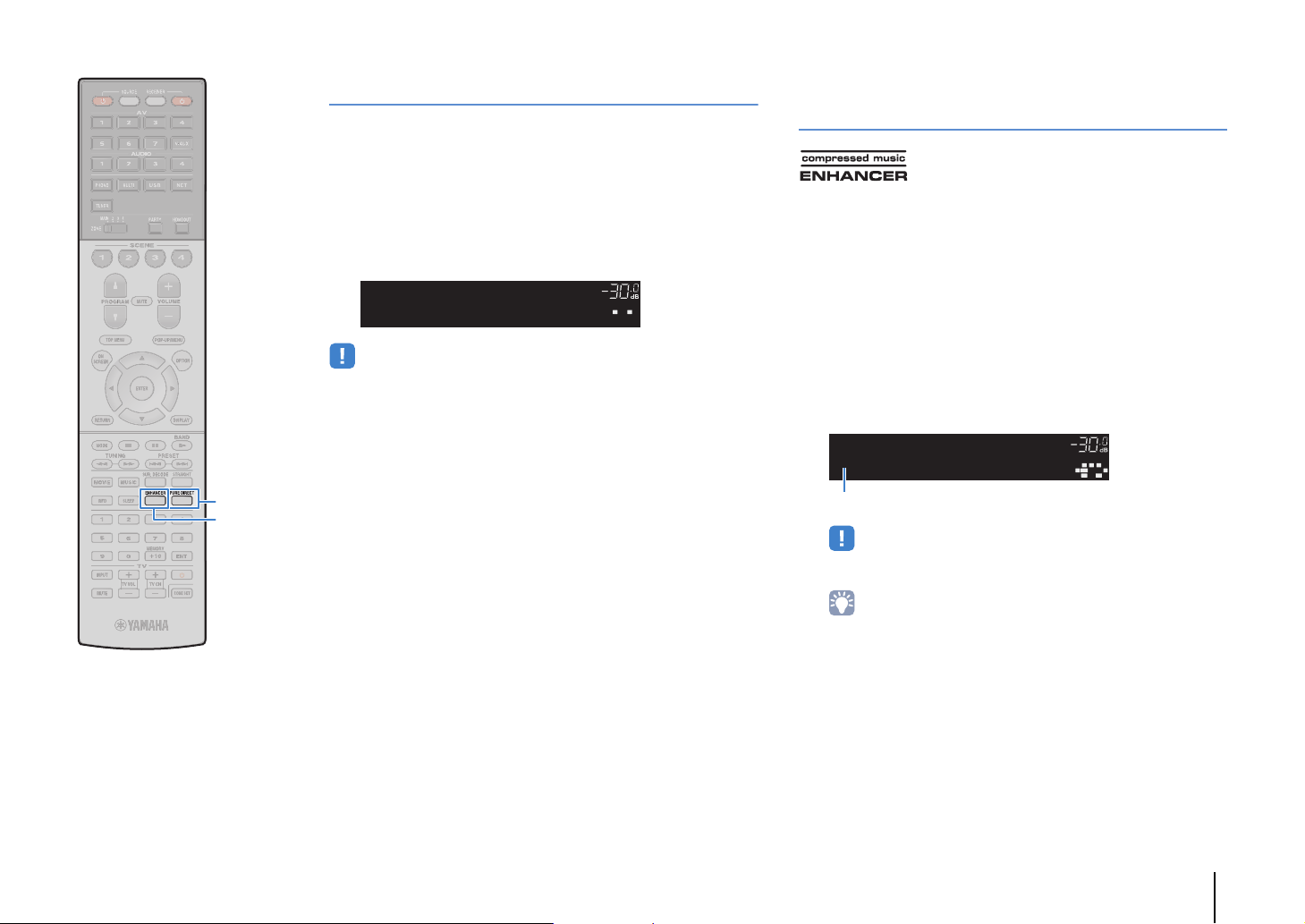
OUT 1INOUT 2
VOLUME
MUTE
DRCADAPTIVE
3
ZONE
2
SBLPL SBRSBPR
SW1SLSW2SW
SR
PL
CL R
PR
STEREO
ENHANCER
SLEEP
HD
TUNED
PRE
AMP
PARTY
ZONE3ZONE
4
HD
TAG
DOCK
PUREDIRECT
OUT 1INOUT 2
VOLUME
MUTE
DRCADAPTIVE
3
ZONE
2
SBLPL SBRSBPR
SW1SLSW2SW
SR
PL
CL R
PR
STEREO
SLEEP
HD
TUNED
PRE
AMP
PARTY
ZONE3ZONE
4
HD
TAG
DOCK
ENHANCER
EnhancerOn
“ENHANCER” lights up
PURE DIRECT
ENHANCER
Enjoying pure high fidelity sound (Pure Direct)
When the Pure Direct mode is enabled, the unit plays back the
selected source with the least circuitry in order to reduce the
electrical noise from other circuitry (such as the front display). It
allows you to enjoy Hi-Fi sound quality.
Press PURE DIRECT.
1
Each time you press the key, the Pure Direct mode is
enabled or disabled.
• When the Pure Direct mode is enabled, the following functions are not available.
– Some settings for the speakers or sound programs
– Operating the on-screen menu and some items in the “Option” menu
– Using the multi-zone function
– Output from the AV OUT jacks
– Viewing information on the front display (when not in operation)
Enjoying compressed music with enhanced sound (Compressed Music Enhancer)
Compressed Music Enhancer adds depth and breadth to the
sound, allowing you to enjoy a dynamic sound close to the original
sound before it was compressed. This function can be used along
with any other sound modes.
In addition, Compressed Music Enhancer enhances the quality of
uncompressed digital audio (such as 2-channel PCM and FLAC)
when “Hi-Res Mode” (p.109) in the “Option” menu is set to “On”
(default).
Press ENHANCER.
1
Each time you press the key, Compressed Music Enhancer
is enabled or disabled.
• Compressed Music Enhancer does not work on signals whose sampling
rate is over 48 kHz.
• You can also use “Enhancer” (p.109) in the “Option” menu to enable/disable
Compressed Music Enhancer.
PLAYBACK ➤ Selecting the sound mode En 75
Page 76

Listening to FM/AM radio
MAIN ZONE z STRAIGHT
PROGRAM
OUT 1INOUT 2
3
ZONE
2
STEREO
SLEEP
HD
TUNED
PRE
AMP
PARTY
ZONE3ZONE
4
HD
TAG
DOCK
FM50/AM9
TUNERFRQSTEP
OUT 1INOUT 2
VOLUME
MUTE
DRCADAPTIVE
3
ZONE
2
SBLPL SBRSBPR
SW1SLSW2SW
SR
PL
CLR
PR
STEREO
SLEEP
HD
TUNED
PRE
AMP
PARTY
ZONE3ZONE
4
HD
TAG
DOCK
FM87.50MHz
TUNER
BAND
TUNING
Numeric keys
You can tune into a radio station by specifying its frequency or
selecting from registered radio stations.
• The radio frequencies differ depending on the country or region where the unit is
being used. The explanation of this section uses a display with frequencies used
in U.K. and Europe models.
• If you cannot obtain good reception on the radio, adjust the direction of the FM/AM
antennas.
Selecting a frequency for reception
Press TUNER to select “TUNER” as the input
1
source.
Press BAND to select a band (FM or AM).
2
Setting the frequency steps
(Asia and General models only)
At the factory, the frequency step setting is set to 50 kHz for FM and
9 kHz for AM. Depending on your country or region, set the
frequency steps to 100 kHz for FM and 10 kHz for AM.
Set the unit to standby mode.
1
When holding down STRAIGHT on the front panel,
2
press MAIN ZONE z.
Press PROGRAM repeatedly to select “TUNER FRQ
3
STEP”.
Press STRAIGHT to select “FM100/AM10”.
4
Press MAIN ZONE z to set the unit to standby
5
mode and turn it on again.
Use the following keys to set a frequency.
3
TUNING: Increase/decrease the frequency. Hold down the
key for about a second to search stations automatically.
Numeric keys: Enter a frequency directly. For example, to
select 98.50 MHz, press “9”, “8”, “5” and “0” (or ENT).
DOCK
TAG
HD
OUT 1INOUT 2
FM98.50MHz
PRE
AMP
PARTY
ZONE
ZONE3ZONE
2
4
SLEEP
STEREO TUNED
3
HD
MUTE
PL
SW1SLSW2SW
SBLPL SBRSBPR
VOLUME
CL R
DRCADAPTIVE
PR
SR
“TUNED” lights up when a signal is received from a radio
station.
“STEREO” also lights up when a stereo signal is received.
• “Wrong Station!” appears when you enter a frequency that is out of
reception range.
• (U.S.A. model only)
You can switch between “Auto” (stereo) and “Mono” (monaural) for FM radio
reception in “Audio Mode” (p.111) in the “Option” menu. When the signal
reception for an FM radio station is unstable, switching to monaural may
improve it. (HD Radio programs are not available when the unit is in the
monaural reception mode.)
• (Except for U.S.A. model)
You can switch between “Stereo” (stereo) and “Mono” (monaural) for FM
radio reception in “FM Mode” (p.111) in the “Option” menu. When the signal
reception for an FM radio station is unstable, switching to monaural may
improve it.
PLAYBACK ➤ Listening to FM/AM radio En 76
Page 77

Registering favorite radio stations (presets)
OUT 1INOUT 2
VOLUME
MUTE
DRCADAPTIVE
3
ZONE
2
SBLPL SBRSBPR
SW1SLSW2SW
SR
PL
CL R
PR
SLEEP
HD
PRE
AMP
PARTY
ZONE3ZONE
4
HD
TAG
DOCK
STEREO TUNED
PresetOK
01:FM98.50MHz
Preset
Preset number
“Empty” (not in use) or the frequency currently registered
OUT 1INOUT 2
VOLUME
MUTE
DRCADAPTIVE
3
ZONE
2
SBLPL SBRSBPR
SW1SLSW2SW
SR
PL
CL R
PR
SLEEP
HD
PRE
AMP
PARTY
ZONE3ZONE
4
HD
TAG
DOCK
STEREO TUNED
01:FM98.50MHz
Preset
You can register up to 40 radio stations as presets. Once you have
registered stations, you can easily tune into them by selecting their
preset numbers.
■ Selecting a preset station
Tune into a registered radio station by selecting its preset number.
Press TUNER to select “TUNER” as the input
1
source.
TUNER
PRESET
Numeric keys
MEMORY
• You can automatically register FM radio stations that have strong signals and HD
Radio stations (U.S.A. model only) by using “Auto Preset” (p.80, p.82).
■ Registering a radio station
Select a radio station manually and register it to a preset number.
Follow “Selecting a frequency for reception” (p.76)
1
to tune into the desired radio station.
• (U.S.A. model only)
To register a specific HD Radio program, select an audio program (p.78)
after tuning into the radio station.
Hold down MEMORY for more than 2 seconds.
2
The first time that you do register a station, the selected
radio station will be registered to the preset number “01”.
Thereafter, each radio station you select will be registered
to the next empty (unused) preset number after the most
recently registered number.
• To select a preset number for registering, press MEMORY once after tuning
into the desired radio station, use PRESET or numeric keys to select a
preset number, and then press MEMORY again.
Press PRESET repeatedly to select the desired radio
2
station.
You can also enter a preset number (01 to 40) directly by
using the numeric keys after pressing PRESET once.
• “No Presets” appears when no radio stations are registered.
• “Wrong Num.” appears when an invalid number is entered.
• “Empty” appears when a preset number not in use is entered.
• To clear preset stations, use “Clear Preset” or “Clear All Preset” (p.80, p.82).
DOCK
TAG
Preset
HD
OUT 1INOUT 2
02:Empty
PRE
AMP
PARTY
ZONE
ZONE3ZONE
2
4
SLEEP
STEREO TUNED
3
HD
FM98.50MHz
MUTE
PL
SW1SLSW2SW
SBLPL SBRSBPR
VOLUME
CL R
DRCADAPTIVE
PR
SR
PLAYBACK ➤ Listening to FM/AM radio En 77
Page 78
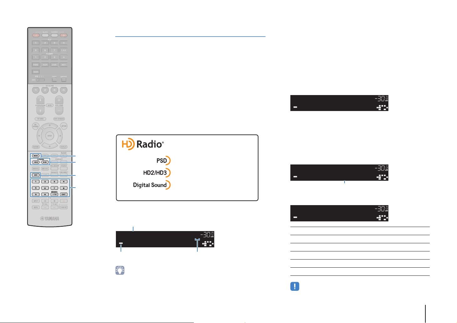
Program Service Data: Contributes to the superior user experience
of HD RadioTechnology. Presents song name, artist, station IDs,
HD2/HD3 Channel Guide, and other relevant data streams.
Adjacent to traditional main stations are extra local FM channels.
These HD2/HD3 Channels provide new, original music as well as
deep cuts into traditional genre.
Digital, CD-quality sound. HD Radio Technology enables local radio
stations to broadcast a clean digital signal. AM sounds like today’s
FM and FM sounds like a CD.
Relative/total program number
(when multiple programs are available)
“HD” lights up Absolute program number
(when multiple programs are available)
OUT 1INOUT 2
VOLUME
MUTE
DRCADAPTIVE
3
ZONE
2
SBLPL SBRSBPR
SW1SLSW2SW
SR
PL
CL R
PR
SLEEP
HD
PRE
AMP
PARTY
ZONE3ZONE
4
TAG
DOCK
TUNED
HD
Category
Info
Item name
OUT 1INOUT 2
VOLUME
MUTE
DRCADAPTIVE
3
ZONE
2
SBLPL SBRSBPR
SW1SLSW2SW
SR
PL
CL R
PR
SLEEP
HD
PRE
AMP
PARTY
ZONE3ZONE
4
TAG
DOCK
TUNED
HD
RhythmandBlu
WXYZ-FM
FM88.9-1
MODE
TUNING
INFO
Numeric keys
ENT
HD Radio™ tuning
(U.S.A. model only)
HD Radio Technology is a new technology that enables FM/AM
radio stations to broadcast programs digitally. Digital broadcasting
provides listeners with radically improved audio quality and
reception as well as new data services. Furthermore, supplemental
program services allow listeners to select from up to 8 HD Radio
programs multicast on a single FM HD Radio channel. For further
information on HD Radio Technology, visit
“http://www.ibiquity.com/”.
The unit is equipped with an HD Radio reception feature, facilitating
CD quality FM broadcasts as well as analog FM stereo quality AM
broadcasts. In addition, the unit can receive both audio and data
(such as song titles, artist names, album titles and program types)
from all HD Radio programs (HD1 to HD8).
When tuning into an HD Radio station
■ Selecting an HD Radio™ audio program
You can select an audio program when the unit is tuned into an HD
Radio station that provides multiple audio programs (up to 8).
Press MODE repeatedly to select a desired audio
1
program.
You can also enter an audio program number (1 to 8)
directly by using the numeric keys. For example, to select
program 3, press 3 and then ENT (or just leave it).
DOCK
TAG
HD2/3
OUT 1INOUT 2
HD
FM88.9MHz3
PRE
AMP
PARTY
ZONE
ZONE3ZONE
2
4
SLEEP
TUNED
3
HD
WXYZ-FM
MUTE
PL
SW1SLSW2SW
SBLPL SBRSBPR
VOLUME
CL R
DRCADAPTIVE
PR
SR
■ Displaying the HD Radio™ information
You can switch the HD Radio information displayed on the front display.
Press INFO.
1
Each time you press the key, the item switches.
About 3 seconds later, the information is displayed.
DOCK
TAG
HD1/3
OUT 1INOUT 2
HD
• The unit is capable of receiving both hybrid and all-digital FM/AM radio stations. If
you cannot search the desired all-digital HD Radio station by holding down
TUNING, enter the frequency directly using the numeric keys.
• When the unit is in the monaural reception mode (p.111), you can tune into the
analog part of a hybrid HD Radio station only.
FM88.9MHz1
PRE
AMP
PARTY
ZONE
ZONE3ZONE
2
4
SLEEP
TUNED
3
HD
WXYZ-FM
VOLUME
MUTE
PL
SW1SLSW2SW
SBLPL SBRSBPR
DRCADAPTIVE
CL R
PR
SR
Station Info Frequency, station name (call sign)
Category Station name (call sign), program category
Artist/Song Station name (call sign), artist name/song title
Album Station name (call sign), album title
DSP Program Frequency, sound program selected on the unit
Audio Decoder Frequency, decoder selected on the unit
• Some audio programs may not provide information depending on the station
or period of time.
PLAYBACK ➤ Listening to FM/AM radio En 78
Page 79

TUNER
Menu operation keys
Cursor keys
ENTER
RETURN
■ HD Radio™ operation on the TV
You can view the HD Radio information or select a radio station on
the TV.
Press TUNER to select “TUNER” as the input
1
source.
The playback screen is displayed on the TV.
❑ Playback screen
3
1
2
4
1 Radio station information
Displays the information of the selected radio station such as the selected
band (FM/AM) and frequency.
When tuning into an HD Radio station, the selected audio program
number and HD Radio information (station name [call sign], program
category, artist name, album name and song title) are also displayed.
Use the cursor keys (q/w) to select scrollable information.
2 HD indicator
Lights up when an HD Radio station signal is received.
3 TUNED/STEREO indicators
“TUNED” lights up when a signal is received from a radio station.
“STEREO” lights up when a stereo signal is received.
4 Operation menu
Press the cursor key (r) and then use the cursor keys (q/w) to select an
item. Press ENTER to confirm the selection.
To close the submenu, press RETURN.
Menu Submenu Function
FM
AM
Tuning (+/-) Selects a frequency.
Auto (+/-) Selects a radio station automatically.
Manual Tuning
Program (+/-)
Memory
Direct Enters a frequency directly.
Browse
Screen Off
Switches to FM/AM.
Selects an audio program (when
multiple audio programs are
available).
Registers the selected station as
presets.
Moves to the browse screen (preset
station list).
Closes the screen display and shows
the background. Press one of the
menu operation keys to redisplay it.
PLAYBACK ➤ Listening to FM/AM radio En 79
Page 80
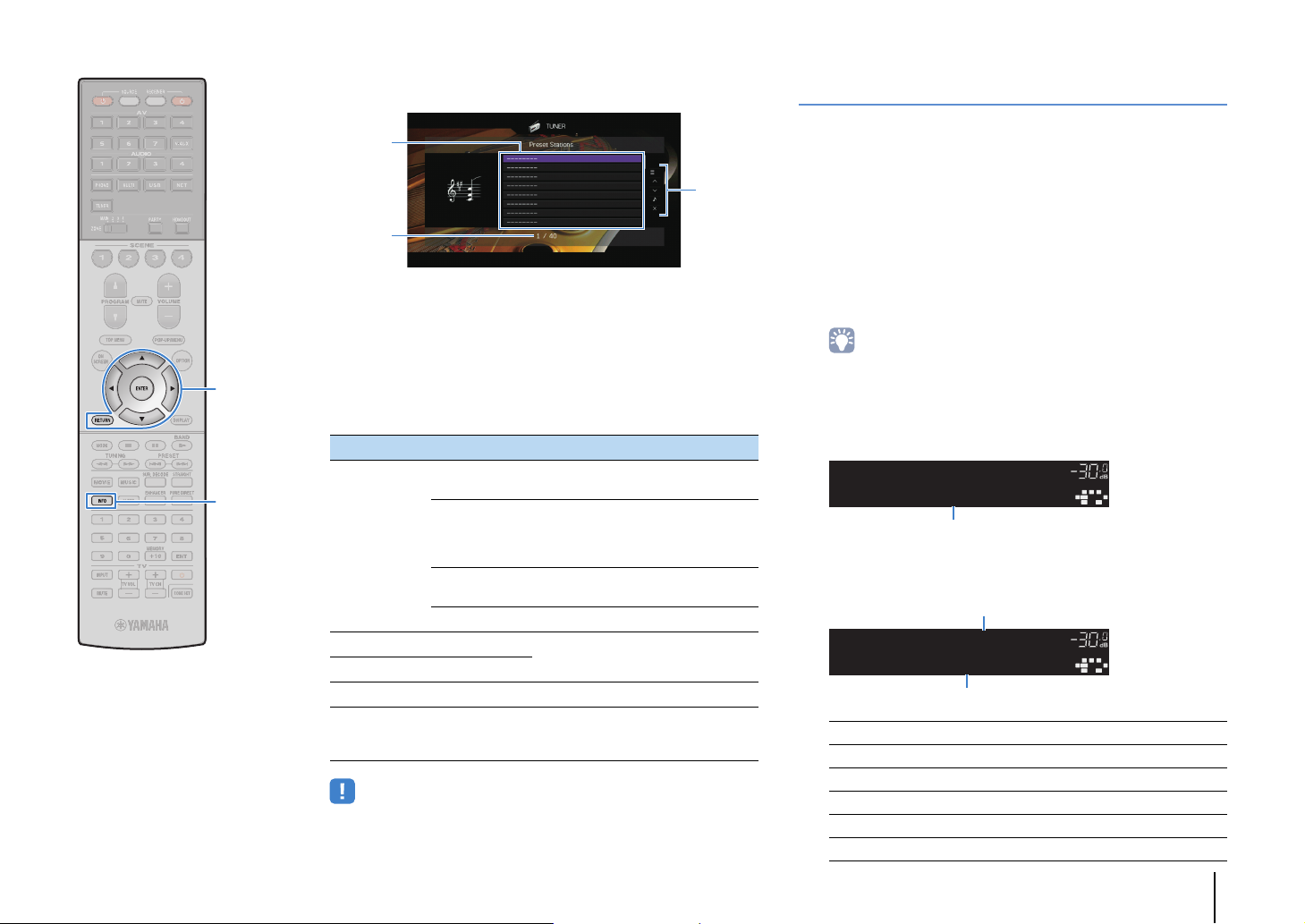
3
2
1
OUT 1INOUT 2
VOLUME
MUTE
DRCADAPTIVE
3
ZONE
2
SBLPL SBRSBPR
SW1SLSW2SW
SR
PL
CL R
PR
SLEEP
HD
PRE
AMP
PARTY
ZONE3ZONE
4
HD
TAG
DOCK
STEREO TUNED
ProgramType
Info
Item name
Information
Frequency (always displayed)
■ Browse screen
Radio Data System tuning
(U.K. and Europe models only)
Radio Data System is a data transmission system used by FM
stations in many countries. The unit can receive various types of
Radio Data System data, such as “Program Service”, “Program
Type,” “Radio Text” and “Clock Time”, when it is tuned into a Radio
Data System broadcasting station.
■
Displaying the Radio Data System information
1 Preset station list
Displays the list of preset stations. Use the cursor keys (q/w) to select a
preset station and press ENTER to tune into it.
Tune into the desired Radio Data System
1
broadcasting station.
2 Preset number
3 Operation menu
Menu operation keys
Cursor keys
ENTER
RETURN
INFO
Press the cursor key (r) and then use the cursor keys (q/w) to select an
item. Press ENTER to confirm the selection.
To close the submenu, press RETURN.
Menu Submenu Function
Memory
Registers the current station to the
preset number selected in the list.
Automatically registers HD Radio
(FM/AM) stations and FM radio
stations with strong signals (up to 40
stations).
Clear the preset station selected in the
list.
Utility
Auto Preset
Clear Preset
Clear All Preset Clear all the preset stations.
1 Page Up
1 Page Down
Moves to the previous/next page of the
list.
Now Playing Moves to the playback screen.
Screen Off
• If HD Radio stations are detected by “Auto Preset”, only the audio program 1
(HD1) will be registered. If you want to register a specific HD Radio program,
register it manually (p.77).
Closes the screen display and shows
the background. Press one of the
menu operation keys to redisplay it.
• We recommend using “Auto Preset” to tune into the Radio Data System
broadcasting stations (p.82).
Press INFO.
2
Each time you press the key, the displayed item changes.
About 3 seconds later, the corresponding information for
the displayed item appears.
DOCK
TAG
HD
OUT 1INOUT 2
FM98.50MHz
PRE
AMP
PARTY
ZONE
ZONE3ZONE
2
4
SLEEP
STEREO TUNED
3
HD
CLASSICS
MUTE
PL
SW1SLSW2SW
SBLPL SBRSBPR
VOLUME
CL R
DRCADAPTIVE
PR
SR
Program Service Program service name
Program Type Current program type
Radio Text Information on the current program
Clock Time Current time
DSP Program Sound mode name
Audio Decoder Decoder name
PLAYBACK ➤ Listening to FM/AM radio En 80
Page 81

• “Program Service”, “Program Type”, “Radio Text”, and “Clock Time” are not
OUT 1INOUT 2
VOLUME
MUTE
DRCADAPTIVE
3
ZONE
2
SBLPL SBRSBPR
SW1SLSW2SW
SR
PL
CL R
PR
SLEEP
HD
PRE
AMP
PARTY
ZONE3ZONE
4
HD
TAG
DOCK
STEREO TUNED
TPFM101.30MHz
TrafficProgram
Finished
Traffic information station (frequency)
displayed if the radio station does not provide the Radio Data System
service.
Operating the radio on the TV
You can view the radio information or select a radio station on the
TV.
TUNER
OPTION
Cursor keys
ENTER
RETURN
■ Receiving traffic information
automatically
When “TUNER” is selected as the input source, the unit
automatically receives traffic information. To enable this function,
follow the procedure below to set the traffic information station.
When “TUNER” is selected as the input source,
1
press OPTION.
Use the cursor keys to select “Traffic Program”
2
(TrafficProgram) and press ENTER.
The traffic information station search will start in 5 seconds.
Press ENTER again to start the search immediately.
• To search upward/downward from the current frequency, press the cursor
keys (q/w) while “READY” is displayed.
• To cancel the search, press RETURN.
• Texts in parentheses denote indicators on the front display.
The following screen appears for about 3 seconds when the
search finishes.
• “TP Not Found” appears for about 3 seconds when no traffic information
stations are found.
• (U.S.A. model only)
See “HD Radio™ operation on the TV” (p.79) to operate the radio on the TV.
Press TUNER to select “TUNER” as the input
1
source.
The playback screen is displayed on the TV.
■ Playback screen
1
2
1 Radio station information
Displays the information of the selected radio station such as the selected
band (FM/AM) and frequency.
(U.K. and Europe models only)
When tuning into a Radio Data System broadcasting station (p.80), the
Radio Data System information (“Program Service”, “Program Type,”
“Radio Text” and “Clock Time”) is also displayed.
2 Band icon
(Except for U.K. and Europe models)
Select this icon and press ENTER to switch between FM and AM.
3 TUNED/STEREO indicators
“TUNED” lights up when a signal is received from a radio station.
“STEREO” lights up when a stereo signal is received.
4 Operation menu
Press the cursor key (r) and then use the cursor keys (q/w) to select an
item. Press ENTER to confirm the selection.
To close the submenu, press RETURN.
3
4
PLAYBACK ➤ Listening to FM/AM radio En 81
Page 82

3
2
1
Menu operation keys
Cursor keys
ENTER
RETURN
Menu Submenu Function
Manual Tuning
Browse
Screen Off
FM
AM
Tuning (+/-) Selects a frequency.
Auto (+/-) Selects a radio station automatically.
Memory
Direct Enters a frequency directly.
(U.K. and Europe models only)
Switches to FM/AM.
Registers the selected station as
presets.
Moves to the browse screen (preset
station list).
Closes the screen display and shows
the background. Press one of the
menu operation keys to redisplay it.
■ Browse screen
1 Preset station list
Displays the list of preset stations. Use the cursor keys (q/w) to select a
preset station and press ENTER to tune into it.
2 Preset number
3 Operation menu
Press the cursor key (r) and then use the cursor keys (q/w) to select an
item. Press ENTER to confirm the selection.
To close the submenu, press RETURN.
Menu Submenu Function
Memory
Utility
1 Page Up
1 Page Down
Now Playing Moves to the playback screen.
Screen Off
Auto Preset
Clear Preset
Clear All Preset Clear all the preset stations.
Registers the current station to the
preset number selected in the list.
Automatically registers FM radio
stations with strong signals (up to 40
stations).
Clear the preset station selected in the
list.
Moves to the previous/next page of the
list.
Closes the screen display and shows
the background. Press one of the
menu operation keys to redisplay it.
• (U.K. and Europe models only)
Only Radio Data System broadcasting stations are stored automatically by “Auto
Preset”.
PLAYBACK ➤ Listening to FM/AM radio En 82
Page 83

Playing back iPod music
The unit (front)
OUT 1INOUT 2
VOLUME
MUTE
DRCADAPTIVE
3
ZONE
2
SBLPL SBRSBPR
SW1SLSW2SW
SR
PL
CL R
PR
SLEEP
HD
PRE
AMP
PARTY
ZONE3ZONE
4
HD
TAG
DOCK
Connected
USB
USB
Cursor keys
ENTER
RETURN
You can play back iPod music on the unit using a USB cable
supplied with the iPod.
• For details on playable iPod devices, see “Supported devices and file formats”
(p.165).
Connecting an iPod
Connect your iPod to the unit with the USB cable supplied with the
iPod.
Connect the USB cable to the iPod.
1
Connect the USB cable to the USB jack.
2
Playback of iPod content
Follow the procedure below to operate the iPod contents and start
playback.
You can control the iPod with the menu displayed on the TV screen.
Press USB to select “USB” as the input source.
1
The browse screen is displayed on the TV.
• If playback is ongoing on your iPod, the playback screen is displayed.
Use the cursor keys to select an item and press
2
ENTER.
If a song is selected, playback starts and the playback
screen is displayed.
• The iPod charges while it is connected to the unit. If you set the unit to standby
mode while the iPod is charging, the iPod continues to charge up to 4 hours. If
“Network Standby” (p.134) in the “Setup” menu is set to “On”, it continues to
charge without limit.
• To return to the previous screen, press RETURN.
• Disconnect the iPod from the USB jack when it is not in use.
• To operate the iPod manually to select content or control playback, switch to the
simple play mode (p.85).
PLAYBACK ➤ Playing back iPod music En 83
Page 84

■ Browse screen
1
5
3
2
4
1
3
2
■ Playback screen
Menu operation keys
Cursor keys
ENTER
RETURN
External device
operation keys
1 Status indicators
Display the current shuffle/repeat settings (p.85) and playback status
(such as play/pause).
2 List name
3 Contents list
Displays the list of iPod content. Use the cursor keys (q/w) to select an
item and press ENTER to confirm the selection.
4 Item number/total
5 Operation menu
Press the cursor key (r) and then use the cursor keys (q/w) to select an
item. Press ENTER to confirm the selection.
Menu Function
1 Page Up
1 Page Down
10 Pages Up
10 Pages Down
Return Returns to the higher-level list.
Now Playing Moves to the playback screen.
Screen Off
Moves to the previous/next page of the list.
Moves 10 pages forward/backward.
Closes the screen display and shows the
background. Press one of the menu operation keys
to redisplay it.
1 Status indicators
Display the current shuffle/repeat settings (p.85) and playback status
(such as play/pause).
2 Playback information
Displays the artist name, album name, song title, and elapsed/remaining
time.
Use the cursor keys (q/w) to select scrollable information.
3 Operation menu
Press the cursor key (r) and then use the cursor keys (q/w) to select an
item. Press ENTER to confirm the selection.
To close the submenu, press RETURN.
Menu Submenu Function
a Resumes playback from pause.
s Stops playback.
d Stops playback temporarily.
Play Control
Browse Moves to the browse screen.
Screen Off
• You can also use the external device operation keys on the remote control to
control playback.
f
Skips forward/backward.
g
h
Searches forward/backward (by holding
down).
j
Closes the screen display and shows the
background. Press one of the menu
operation keys to redisplay it.
PLAYBACK ➤ Playing back iPod music En 84
Page 85
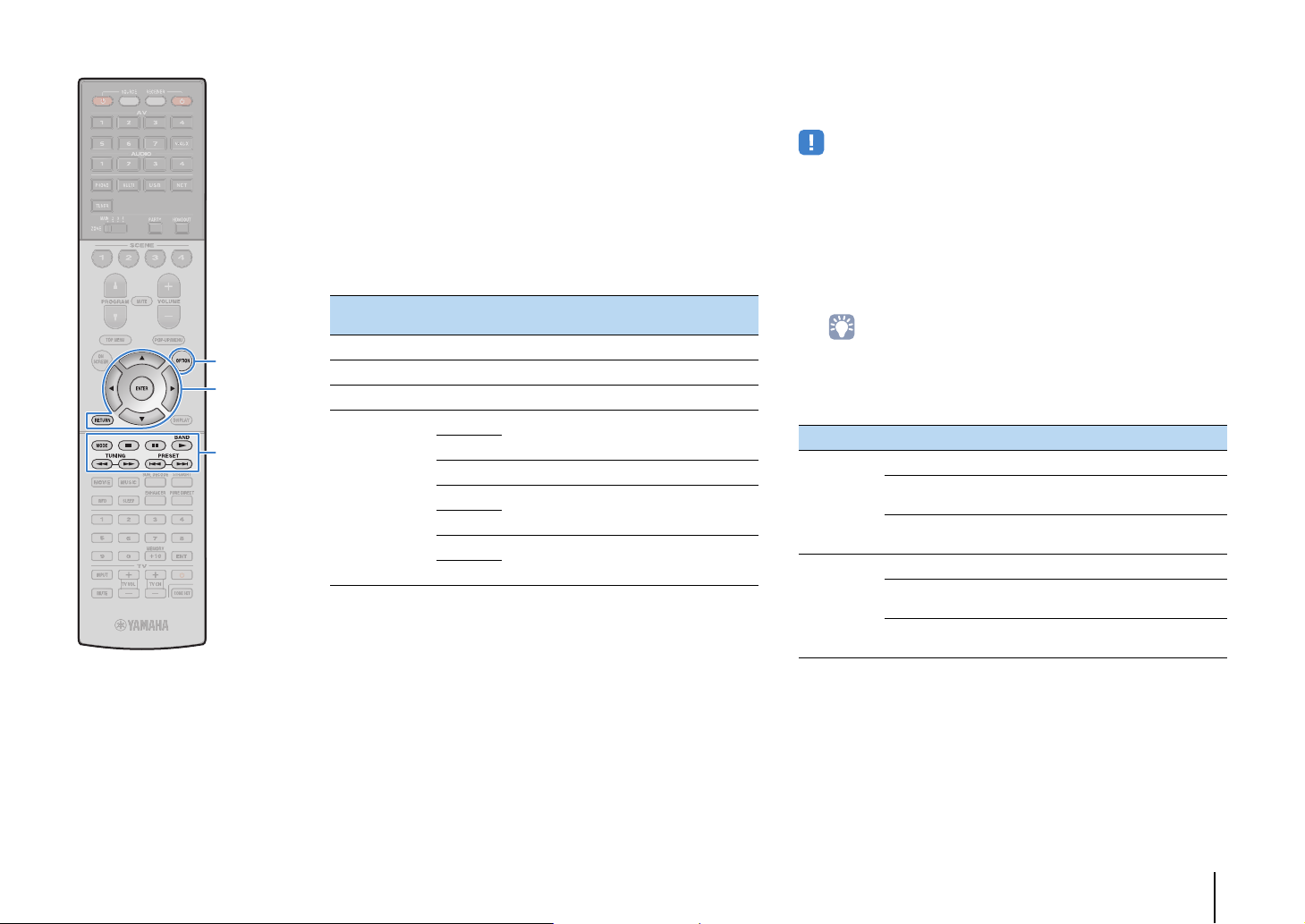
OPTION
Cursor keys
ENTER
RETURN
External device
operation keys
MODE
■ Operating the iPod itself or remote control
(simple play)
Press MODE to switch to the simple play mode.
1
The TV menu screen turns off and iPod operations are
enabled.
To display the TV menu screen, press MODE again.
Operate your iPod itself or the remote control to
2
start playback.
Operational remote control
keys
Cursor keys Select an item.
ENTER Confirms the selection.
RETURN Returns to the previous screen.
External device
operation keys
Function
a
Starts playback or stops playback
temporarily.
d
s Stops playback.
f
Skips forward/backward.
g
h
Searches forward/backward (by holding
down).
j
■ Shuffle/repeat settings
You can configure the shuffle/repeat settings of your iPod.
• During simple play, configure the shuffle/repeat settings directly on your iPod or
press MODE to display the TV menu screen and then follow the procedure below.
When “USB” is selected as the input source, press
1
OPTION.
Use the cursor keys to select “Shuffle” (Shuffle) or
2
“Repeat” (Repeat) and press ENTER.
• To return to the previous screen during menu operations, press RETURN.
• Texts in parentheses denote indicators on the front display.
Use the cursor keys (e/r) to select a setting.
3
Item Setting Function
Off (Off) Turns off the shuffle function.
Shuffle
(Shuffle)
Repeat
(Repeat)
Songs (Songs)
Albums
(Albums)
Off (Off) Turns off the repeat function.
One (One)
All (All)
Plays back songs in random order.
“x” appears in the TV screen.
Plays back albums in random order.
“x” appears in the TV screen.
Plays back the current song repeatedly.
“c” appears in the TV screen.
Plays back all songs repeatedly.
“v” appears in the TV screen.
To exit from the menu, press OPTION.
4
PLAYBACK ➤ Playing back iPod music En 85
Page 86
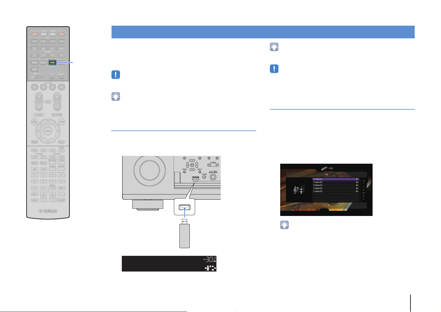
The unit (front)
USB storage device
OUT 1INOUT 2
VOLUME
MUTE
DRCADAPTIVE
3
ZONE
2
SBLPL SBRSBPR
SW1SLSW2SW
SR
PL
CL R
PR
SLEEP
HD
PRE
AMP
PARTY
ZONE3ZONE
4
HD
TAG
DOCK
Connected
USB
USB
Playing back music stored on a USB storage device
You can play back music files stored on a USB storage device on
the unit.
The unit supports USB mass storage class devices (FAT16 or
FAT32 format).
• If the USB storage device contains many files, it may take time to load the them. In
this case, “Loading...” appears in the front display.
• The audio may be interrupted while using the wireless network connection. In this
case, use the wired network connection.
• For details on playable file formats, see “Supported devices and file formats”
(p.165).
Connecting a USB storage device
Connect the USB storage device to the USB jack.
1
• Stop playback of the USB storage device before disconnect it from the USB jack.
• Connect a USB memory device directly to the USB jack of the unit. Do not use
extension cables.
Playback of USB storage device contents
Follow the procedure below to operate the USB storage device
contents and start playback.
You can control the USB memory device with the menu displayed
on the TV screen.
Press USB to select “USB” as the input source.
1
The browse screen is displayed on the TV.
• If playback is ongoing on your USB storage device, the playback screen is
displayed.
PLAYBACK ➤ Playing back music stored on a USB storage device En 86
Page 87
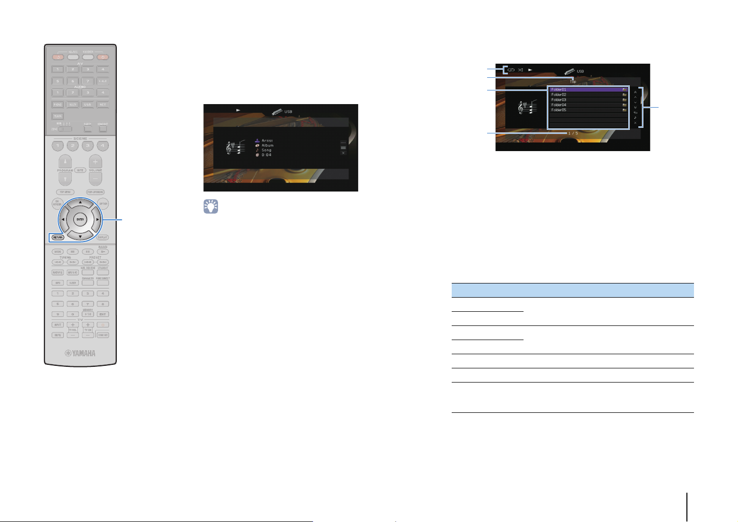
Menu operation keys
Cursor keys
ENTER
RETURN
Use the cursor keys to select an item and press
2
ENTER.
If a song is selected, playback starts and the playback
screen is displayed.
• To return to the previous screen, press RETURN.
• Files not supported by the unit cannot be selected.
• If the unit detects a series of unsupported files (such as images and hidden
files) during playback, playback stops automatically.
■ Browse screen
1
2
3
5
4
1 Status indicators
Display the current shuffle/repeat settings (p.88) and playback status
(such as play/pause).
2 List name
3 Contents list
Displays the list of USB storage device contents. Use the cursor keys
(q/w) to select an item and press ENTER to confirm the selection.
4 Item number/total
5 Operation menu
Press the cursor key (r) and then use the cursor keys (q/w) to select an
item. Press ENTER to confirm the selection.
Menu Function
1 Page Up
1 Page Down
10 Pages Up
10 Pages Down
Return Returns to the higher-level list.
Now Playing Moves to the playback screen.
Screen Off
Moves to the previous/next page of the list.
Moves 10 pages forward/backward.
Closes the screen display and shows the
background. Press one of the menu operation keys
to redisplay it.
PLAYBACK ➤ Playing back music stored on a USB storage device En 87
Page 88

■ Playback screen
1
3
2
■ Shuffle/repeat settings
You can configure the shuffle/repeat settings for playback of USB
storage device contents.
When “USB” is selected as the input source, press
1
OPTION.
Use the cursor keys to select “Shuffle” (Shuffle) or
2
“Repeat” (Repeat) and press ENTER.
OPTION
Menu operation keys
Cursor keys
ENTER
RETURN
External device
operation keys
1 Status indicators
Display the current shuffle/repeat settings (p.88) and playback status
(such as play/pause).
2 Playback information
Displays the artist name, album name, song title, and elapsed time.
Use the cursor keys (q/w) to select scrollable information.
3 Operation menu
Press the cursor key (r) and then use the cursor keys (q/w) to select an
item. Press ENTER to confirm the selection.
To close the submenu, press RETURN.
Menu Submenu Function
a Resumes playback from pause.
s Stops playback.
Play Control
Browse Moves to the browse screen.
Screen Off
• You can also use the external device operation keys (a, s, d, f, g) on
the remote control to control playback.
d Stops playback temporarily.
f
g
Skips forward/backward.
Closes the screen display and shows the
background. Press one of the menu
operation keys to redisplay it.
• To return to the previous screen during menu operations, press RETURN.
• Texts in parentheses denote indicators on the front display.
Use the cursor keys (e/r) to select a setting.
3
Item Setting Function
Off (Off) Turns off the shuffle function.
Shuffle
(Shuffle)
Repeat
(Repeat)
To exit from the menu, press OPTION.
4
On (On)
Off (Off) Turns off the repeat function.
One (One)
All (All)
Plays back songs in the current album
(folder) in random order.
“x” appears on the TV screen.
Plays back the current song repeatedly.
“c” appears on the TV screen.
Plays back all songs in the current album
(folder) repeatedly.
“v” appears on the TV screen.
PLAYBACK ➤ Playing back music stored on a USB storage device En 88
Page 89

Playing back music stored on media servers (PCs/NAS)
You can play back music files stored on your PC or DLNA-compatible NAS on the unit.
• To use this function, the unit and your PC must be connected to the same router (p.43). You can check
whether the network parameters (such as the IP address) are properly assigned to the unit in “Network”
(p.143) in the “Information” menu.
• The audio may be interrupted while using the wireless network connection. In this case, use the wired
network connection.
• For details on playable file formats, see “Supported devices and file formats” (p.165).
Media sharing setup
To play back music files stored on your PC or DLNA-compatible NAS, first you need to
configure the media sharing setting on each music server.
■ For a PC with Windows Media Player installed
❑ For Windows Media Player 12
Start Windows Media Player 12 on your PC.
1
Select “Stream”, then “Turn on media streaming”.
2
Click “Turn on media streaming”.
3
Select “Allowed” from the drop-down list next to the unit’s model
4
name.
❑ For Windows Media Player 11
Start Windows Media Player 11 on your PC.
1
Select “Library”, then “Media Sharing”.
2
Check the “Share my media to” box, select the unit’s icon, and click
3
“Allow”.
Click “OK” to exit.
4
• For details on media sharing settings, refer to Windows Media Player help.
■ For a PC or a NAS with other DLNA server software
installed
Refer to the instruction manual for the device or software and configure the media
sharing settings.
Click “OK” to exit.
5
PLAYBACK ➤ Playing back music stored on media servers (PCs/NAS) En 89
Page 90
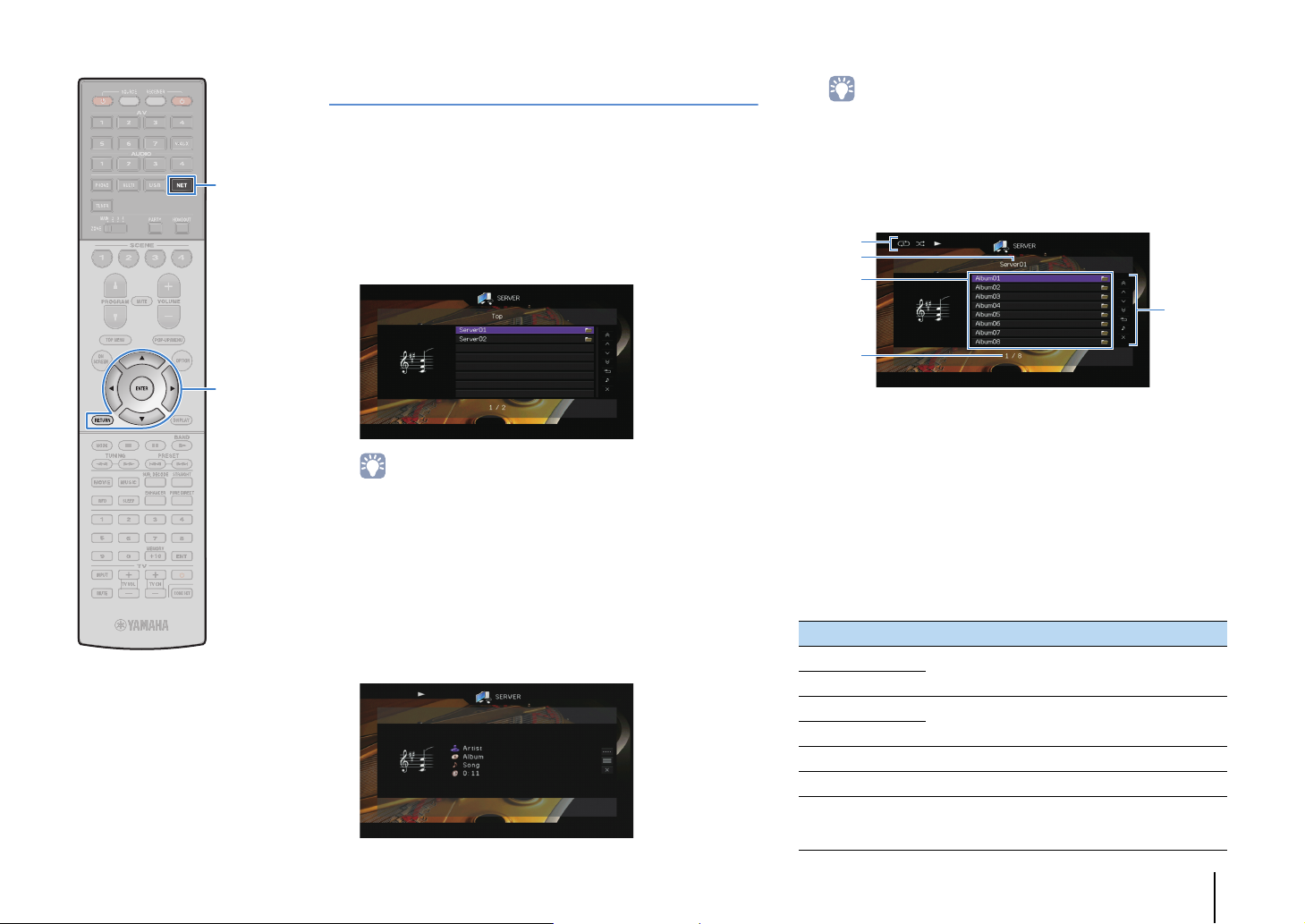
1
5
3
2
4
NET
Menu operation keys
Cursor keys
ENTER
RETURN
Playback of PC music contents
Follow the procedure below to operate the PC music contents and
start playback.
You can control the PC/NAS with the menu displayed on the TV
screen.
Press NET repeatedly to select “SERVER” as the
1
input source.
The browse screen is displayed on the TV.
• If playback of a music file selected from the unit is ongoing on your PC, the
playback screen is displayed.
Use the cursor keys to select a music server and
2
press ENTER.
Use the cursor keys to select an item and press
3
ENTER.
If a song is selected, playback starts and the playback
screen is displayed.
• To return to the previous screen, press RETURN.
• Files not supported by the unit cannot be selected.
• If the unit detects a series of unsuppor ted files (such as images and hidden
files) during playback, playback stops automatically.
■ Browse screen
1 Status indicators
Display the current shuffle/repeat settings (p.91) and playback status
(such as play/pause).
2 List name
3 Contents list
Displays the list of PC content. Use the cursor keys (q/w) to select an
item and press ENTER to confirm the selection.
4 Item number/total
5 Operation menu
Press the cursor key (r) and then use the cursor keys (q/w) to select an
item. Press ENTER to confirm the selection.
Menu Function
1 Page Up
1 Page Down
10 Pages Up
10 Pages Down
Return Returns to the higher-level list.
Now Playing Moves to the playback screen.
Screen Off
Moves to the previous/next page of the list.
Moves 10 pages forward/backward.
Closes the screen display and shows the
background. Press one of the menu operation keys
to redisplay it.
PLAYBACK ➤ Playing back music stored on media servers (PCs/NAS) En 90
Page 91
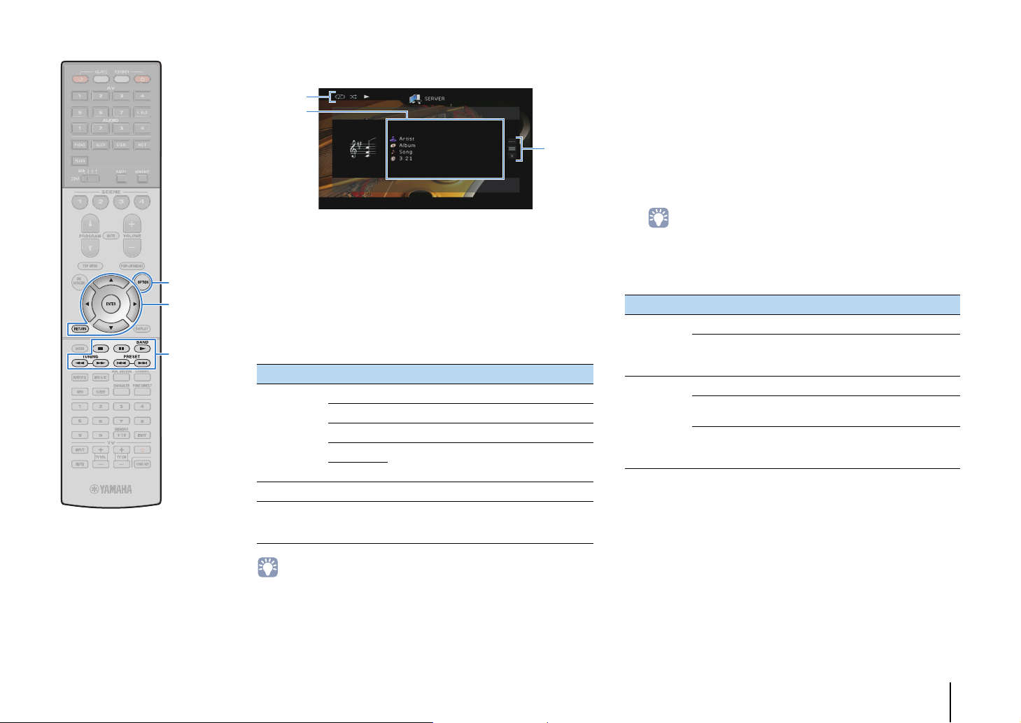
■ Playback screen
1
3
2
■ Shuffle/repeat settings
You can configure the shuffle/repeat settings for the playback of PC
music content.
When “SERVER” is selected as the input source,
1
press OPTION.
Use the cursor keys to select “Shuffle” (Shuffle) or
2
“Repeat” (Repeat) and press ENTER.
OPTION
Menu operation keys
Cursor keys
ENTER
RETURN
External device
operation keys
1 Status indicators
Display the current shuffle/repeat settings (p.91) and playback status
(such as play/pause).
2 Playback information
Displays the artist name, album name, song title, and elapsed time.
Use the cursor keys (q/w) to select scrollable information.
3 Operation menu
Press the cursor key (r) and then use the cursor keys (q/w) to select an
item. Press ENTER to confirm the selection.
To close the submenu, press RETURN.
Menu Submenu Function
a Resumes playback from pause.
s Stops playback.
Play Control
Browse Moves to the browse screen.
Screen Off
• You can also use the external device operation keys (a, s, d, f, g) on
the remote control to control playback.
• You can also use a DLNA-compatible Digital Media Controller (DMC) to control
playback. For details, see “DMC Control” (p.113).
d Stops playback temporarily.
f
g
Skips forward/backward.
Closes the screen display and shows the
background. Press one of the menu operation
keys to redisplay it.
• To return to the previous screen during menu operations, press RETURN.
• Text in parentheses denotes indicators on the front display.
Use the cursor keys (e/r) to select a setting.
3
Item Setting Function
Off (Off) Turns off the shuffle function.
Shuffle
(Shuffle)
Repeat
(Repeat)
To exit from the menu, press OPTION.
4
On (On)
Off (Off) Turns off the repeat function.
One (One)
All (All)
Plays back songs in the current album
(folder) in random order.
“x” appears on the TV screen.
Plays back the current song repeatedly.
“c” appears on the TV screen.
Plays back all songs in the current album
(folder) repeatedly.
“v” appears on the TV screen.
PLAYBACK ➤ Playing back music stored on media servers (PCs/NAS) En 91
Page 92
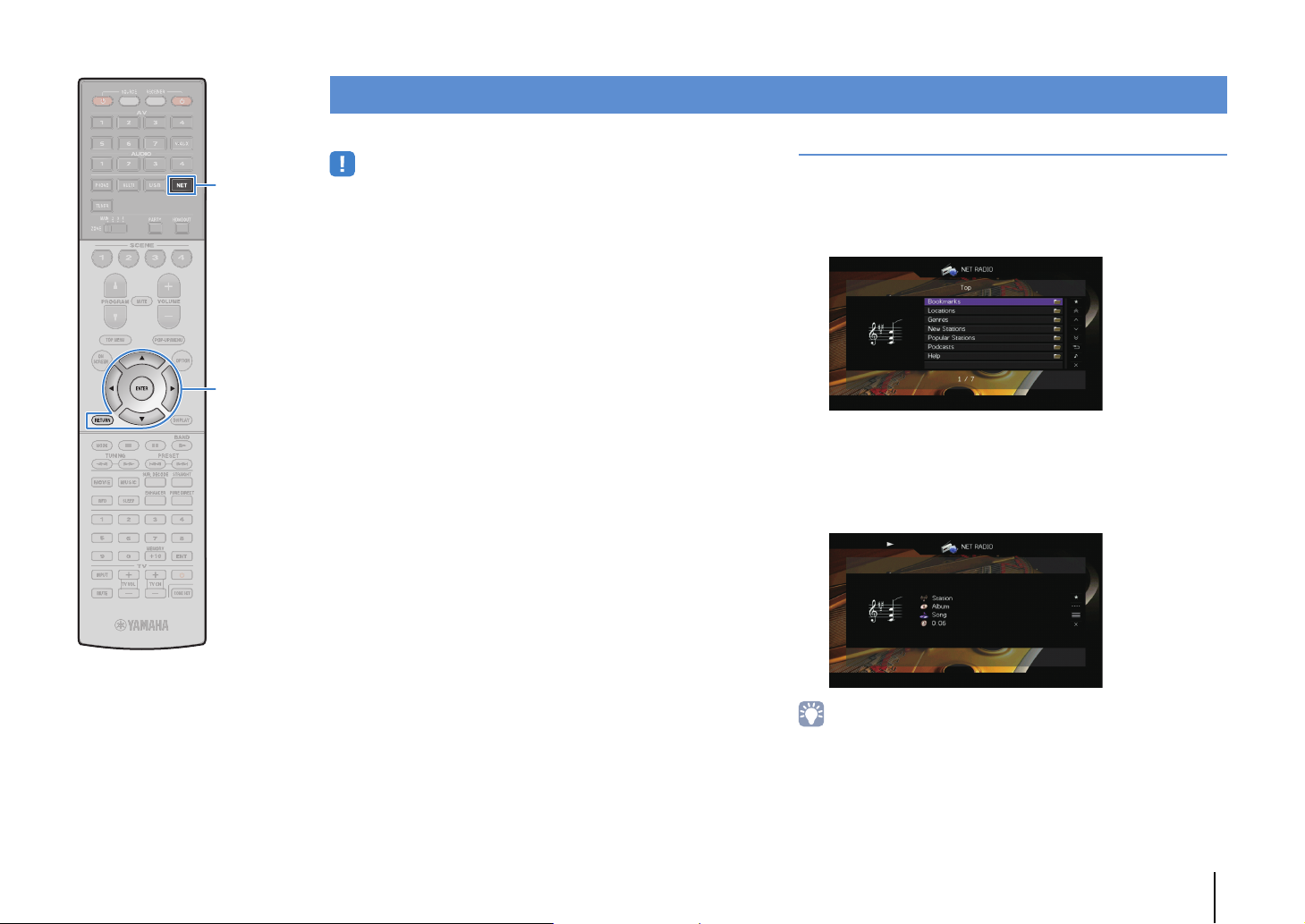
Listening to Internet radio
NET
Cursor keys
ENTER
RETURN
You can listen to Internet radio stations from all over the world.
• To use this function, the unit must be connected to the Internet (p.43). You can
check whether the network parameters (such as the IP address) are properly
assigned to the unit in “Network” (p.143) in the “Information” menu.
• You may not be able to receive some Internet radio stations.
• The unit uses the vTuner Internet radio station database service.
• This service may be discontinued without notice.
Playback of Internet radio
Press NET repeatedly to select “NET RADIO” as the
1
input source.
The browse screen is displayed on the TV.
Use the cursor keys to select an item and press
2
ENTER.
If an Internet radio station is selected, playback starts and
the playback screen is displayed.
• To return to the previous screen, press RETURN.
PLAYBACK ➤ Listening to Internet radio En 92
Page 93

■ Browse screen
1
5
3
2
4
1
3
2
■ Playback screen
Menu operation keys
Cursor keys
ENTER
RETURN
External device
operation keys
1 Playback indicator
2 List name
3 Contents list
Displays the list of Internet radio content. Use the cursor keys (q/w) to
select an item and press ENTER to confirm the selection.
4 Item number/total
5 Operation menu
Press the cursor key (r) and then use the cursor keys (q/w) to select an
item. Press ENTER to confirm the selection.
Menu Function
Bookmark On
(Bookmark Off)
1 Page Up
1 Page Down
10 Pages Up
10 Pages Down
Return Returns to the higher-level list.
Now Playing Moves to the playback screen.
Screen Off
Adds/removes the station selected in the list to/from
the “Bookmarks” folder (p.94).
Moves to the previous/next page of the list.
Moves 10 pages forward/backward.
Closes the screen display and shows the
background. Press one of the menu operation keys
to redisplay it.
1 Playback indicator
2 Playback information
Displays the station name, album name, song title, and elapsed time.
Use the cursor keys (q/w) to select scrollable information.
3 Operation menu
Press the cursor key (r) and then use the cursor keys (q/w) to select an
item. Press ENTER to confirm the selection.
To close the submenu, press RETURN.
Menu Submenu Function
Bookmark On
Play Control s Stops playback.
Browse Moves to the browse screen.
Screen Off
• You can also use the external device operation key (s) on the remote control to
stop playback.
• Some information may not be available depending on the station.
Adds the current station to the
“Bookmarks” folder (p.94).
Closes the screen display and shows the
background. Press one of the menu
operation keys to redisplay it.
PLAYBACK ➤ Listening to Internet radio En 93
Page 94

Registering favorite Internet radio stations (bookmarks)
You can switch the language.
Enter the vTuner ID in this area.
Cursor keys
ENTER
By registering your favorite Internet radio stations to “Bookmarks”,
you can quickly access to them from the “Bookmarks” folder in the
browse screen.
■ Registering the station on the
browse/playback screen
Select the desired Internet radio station in the
1
browse screen or start playback of it to display the
playback screen.
Press the cursor key (r) to select “Bookmark On”
2
and press ENTER.
The selected station is added to the “Bookmarks” folder.
• To remove stations from the “Bookmarks” folder, select the station in the
“Bookmarks” folder and then “Bookmark Off”.
■ Registering the station on the vTuner
website
Select any of Internet radio stations on the unit.
1
This operation is necessary to register the radio station for
the first time.
Check the vTuner ID of the unit.
2
You can find the vTuner ID (MAC address of the unit) in
“Network” (p.143) in the “Information” menu.
Access the vTuner website
3
(http://yradio.vtuner.com/) with the web browser on
your PC and enter the vTuner ID.
• To use this feature, you need to create your personal account. Create your
account using your e-mail address.
Register your favorite radio stations.
4
Click the “Add” icon (❤+) next to the station name.
• To remove the station from the “Bookmarks” folder, select “Bookmarks” in
the Home screen, and then click the “Remove” icon (❤–) next to the station
name.
PLAYBACK ➤ Listening to Internet radio En 94
Page 95

Playing back music with AirPlay
PC
iTunes
Router
(wired or wireless)
iPhone/iPad/
iPod touch
The unit
iTunes (example) iPod (example)
iTunes (example) iPod (example)
Network name of the unit
The AirPlay function allows you to play back iTunes/iPod music on the unit via network.
• To use this function, the unit and your PC or iPod must be connected to the same router. You can check
whether the network parameters (such as the IP address) are properly assigned to the unit in “Network”
(p.143) in the “Information” menu.
• When using a multiple SSID router, access to the unit might be restricted depending on the SSID to
connect. Connect the iPod to the SSID which can access the unit.
• For details on supported iPod devices, see “Supported devices and file formats” (p.165).
Playback of iTunes/iPod music contents
Follow the procedure below to play back iTunes/iPod music contents on the unit.
Turn on the unit, and start iTunes on the PC or display the playback
1
screen on the iPod.
If the iTunes/iPod recognizes the unit, the AirPlay icon ( ) appears.
• If the icon does not appear, check whether the unit and PC/iPod are connected to the router properly.
On the iTunes/iPod, click (tap) the AirPlay icon and select the unit
2
(network name of the unit) as the audio output device.
Select a song and start playback.
3
The unit automatically selects “AirPlay” as the input source and starts playback.
The playback screen is displayed on the TV.
PLAYBACK ➤ Playing back music with AirPlay En 95
Page 96

• You can turn on the unit automatically when starting playback on iTunes or iPod by
iTunes (example of English version)
Check this box
setting “Network Standby” (p.134) in the “Setup” menu to “On”.
• You can edit the network name (the unit’s name on the network) displayed on
iTunes/iPod in “Network Name” (p.135) in the “Setup” menu.
• If you select the other input source on the unit during playback, playback on the
iTunes/iPod stops automatically.
• You can adjust the unit’s volume from the iTunes/iPod during playback. To disable
volume controls from iTunes/iPod, set “Volume Interlock” (p.113) in the “Input”
menu to “Off”.
Caution
• When you use iTunes/iPod controls to adjust volume, the volume may be
unexpectedly loud. This could result in damage to the unit or speakers. If the
volume suddenly increases during playback, stop playback on the iTunes/iPod
immediately.
Menu Submenu Function
a Resumes playback from pause.
Play Control
d Stops playback temporarily.
f
g
Skips forward/backward.
Closes the screen display and shows the
Screen Off
• You can also use the external device operation keys (a, s, d, f, g) on
the remote control to control playback.
background. Press one of the menu operation
keys to redisplay it.
Menu operation keys
Cursor keys
ENTER
RETURN
External device
operation keys
■ Playback screen
1
2
3
1 Playback indicator
2 Playback information
Displays the artist name, album name, song title, and elapsed/remaining
time.
Use the cursor keys (q/w) to select scrollable information.
3 Operation menu
Press the cursor key (r) and then use the cursor keys (q/w) to select an
item. Press ENTER to confirm the selection.
To close the submenu, press RETURN.
• To control iTunes playback with the remote control of the unit, you need to
configure the iTunes preferences to enable iTunes control from remote speakers
in advance.
PLAYBACK ➤ Playing back music with AirPlay En 96
Page 97
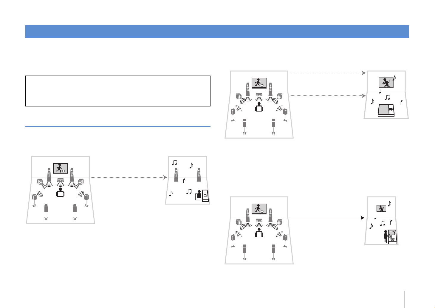
Playing back videos/audio in multiple rooms (multi-zone)
Living room (main zone)
Study room
(Zone2 and/or Zone3)
Audio (SPEAKERS or ZONE OUT)
Living room (main zone)
Guest room
(Zone2 or Zone3)
Audio (SPEAKERS or ZONE OUT)
Video (ZONE OUT or HDMI)
Living room (main zone)
Kitchen
(Zone2 or Zone4)
Video/audio (HDMI)
The multi-zone function allows you to play back different input sources in the room
where the unit is installed (main zone) and in other rooms (Zone2, Zone3 and Zone4).
For example, while you are watching TV in the living room (main zone), another person
can listen to PC music in the study room (Zone2), and another can listen to radio in the
guest room (Zone3) and play DVD in the kitchen (Zone4).
• Video/audio signals that can be output to each zone vary depending on how you connect the device in
each zone to the unit’s output jacks. For details, see “Multi-zone output” (p.167).
• Since there are many possible ways to use the unit in a multi-zone configuration, we recommend that
you consult with your nearest authorized Yamaha dealer or service center about the multi-zone
connections that best meet your requirements.
Multi-zone configuration examples
■ Enjoying music in other rooms
You can enjoy music using speakers placed in other rooms.
■ Enjoying videos/music in other rooms
You can enjoy videos/music using TVs placed in other rooms.
❑ Enjoying videos/music using a TV and speakers
Connections
TV (for analog video playback): p.99
TV (for digital video playback): p.99
Speakers (connecting to the unit directly): p.32
Speakers (using an external amplifier): p.98
❑
Enjoying videos/music using only a TV
Connections
Speakers (connecting to the unit directly): p.32
Speakers (using an external amplifier): p.98
Connection
TV: p.99
PLAYBACK ➤ Playing back videos/audio in multiple rooms (multi-zone) En 97
Page 98

ZONE OUT/PRE OUT
ZONE 2 /
F.PRESENSE
ZONE 3 /
R.PRESENSE
L
R
L
R
AUDIO
The unit (rear)
ZONE OUT
(ZONE 2 or ZONE 3) jacks
Zone2 or Zone3
Main zone
External amplifier
Audio input
(analog stereo)
Preparing the multi zone system
Connect the device that will be used in other rooms to the unit.
Caution
• Remove the unit’s power cable from the AC wall outlet before connecting speakers or an external
amplifier.
• Ensure that the core wires of the speaker cable do not touch one another or come into contact with the
unit’s metal parts. Doing so may damage the unit or the speakers. If the speaker cables short circuit,
“Check SP Wires” will appear on the front display when the unit is turned on.
■ Connecting speakers to play back audio
Connect speakers to play back audio in Zone2 or Zone3. The connection method
varies depending on the amplifier being used (the unit or an external amplifier).
❑ Using the unit’s internal amplifier
Connect the speakers placed in Zone2 or Zone3 to the unit with speaker cables. For
details, see “Connecting Zone2/3 speakers” (p.32).
❑ Using an external amplifier
Connect the external amplifier placed in Zone2 or Zone3 to the unit with a stereo pin
cable and connect speakers to the external amplifier.
• (RX-A3040 only)
You cannot use an external amplifier for Zone2 when the ZONE OUT/PRE OUT jacks are set to output front
presence channel audio in “Power Amp Assign” (p.124) in the “Setup” menu. Also, you cannot use an
external amplifier for Zone3 when the ZONE OUT/PRE OUT jacks are configured to output rear presence
channel audio.
PLAYBACK ➤ Playing back videos/audio in multiple rooms (multi-zone) En 98
Page 99
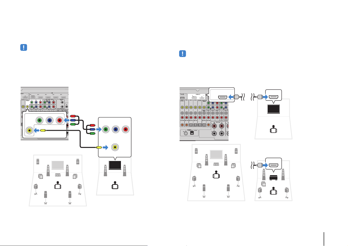
■ Connecting a video monitor to play back analog videos
The unit (rear)
ZONE OUT jacks
(COMPONENT VIDEO or VIDEO)
Zone2 or Zone3
Main zone
Video input
(component video or
composite video)
HDMI OUT
(ZONE OUT)
2
The unit (rear)
HDMI OUT 2
(ZONE OUT) jack
Zone4
Main zone
HDMI input
(Example: using a TV)
HDMI input
(Example: using an AV amplifier)
Zone2 or Zone4
Connect a video monitor to watch analog videos at Zone2 or Zone3. Depending on the
video input jacks available on your video monitor, choose one of the video connection
methods.
• The video conversion between the analog video jacks does not work for multi-zone video output. To watch
videos played back on a video device on the zone video monitor, you need to connect the video monitor to
the unit in the same way as the video device. For example, if you want to watch videos input from the DVD
player via a component video cable, connect the video monitor to the MONITOR OUT/ZONE OUT
(COMPONENT VIDEO) jacks with a component video cable.
• On-screen operations are not available for Zone3 when “HDMI OUT2 Assign” (p.138) in the “Setup” menu
is set to “Zone2”.
■ Connecting an HDMI-compatible device to play back
videos/audio
Connect an HDMI-compatible device (such as a TV) to play back videos/audio at
Zone2 or Zone4. If you connect an AV amplifier, you can enjoy multi-channel playback
in another room (Zone4).
• To watch videos played back on a video device at Zone2 or Zone4, you need to connect the video device to
the unit with an HDMI cable (p.38).
• We recommend that you disable HDMI Control on the playback devices connected to the unit.
• On-screen operations are not available for Zone4.
MONITOR OUT/
Y
ZONE OUT
V
To assign the MONITOR OUT/ZONE OUT jacks to the video monitor for Zone2 or
Zone3, set “Monitor Out Assign” (p.137) in the “Setup” menu to “Zone2” or “Zone3”.
PB PR
P
R
P
B
Y
COMPONENT VIDEO
YPB PR
R
P
P
B
Y
V
VIDEO
HDMI
HDMI
HDMI
HDMI
HDMI
To assign the HDMI OUT 2 (ZONE OUT) jack to Zone2 or Zone4, set
(p.138)
in the “Setup” menu to “Zone2” or “Zone4”.
“HDMI OUT2 Assign”
PLAYBACK ➤ Playing back videos/audio in multiple rooms (multi-zone) En 99
Page 100

• When the HDMI OUT 2 (ZONE OUT) jack is assigned to Zone2, you can enable/disable the audio output
The unit (rear)
REMOTE IN/OUT 1–2 jacks
External device
(such as a CD player)
Remote control
Infrared
signal
receiver
Zone2, Zone3 or Zone4
Main zone
Infrared signal
transmitter
from the HDMI OUT 2 jack by setting “Audio Output” (p.138) in the “Setup” menu to “On” or “Off” (default).
• You can also use speakers placed in Zone2 to output audio (p.32).
• Videos/audio interruptions may happen in another zone when any of the following operations is
performed.
– Tuning on/off a TV connected to the unit via HDMI or switching the TV input
– Enabling/disabling a zone output or selecting its input source
– Changing the sound mode or audio settings (such as “Extended Surround”)
■ Operating the unit from another room
(remote connection)
You can operate the unit and external devices from Zone2, Zone3 or Zone4 using the
supplied remote control if you connect an infrared signal receiver/emitter to the unit’s
REMOTE IN/OUT 1 or REMOTE IN/OUT 2 jacks.
• To operate external devices with the supplied remote control, you must register a remote control code for
each device before using (p.148).
REMOTE
12
IN
OUT IN OUT
PLAYBACK ➤ Playing back videos/audio in multiple rooms (multi-zone) En 100
 Loading...