

Yamaha R-S700BL, R-S500BL User Manual

Receiver
U
OWNER’S MANUAL
IMPORTANT SAFETY INSTRUCTIONS
IMPORTANT SAFETY INSTRUCTIONS
CAUTION
RISK OF ELECTRIC SHOCK
DO NOT OPEN
CAUTION: TO REDUCE THE RISK OF
ELECTRIC SHOCK, DO NOT REMOVE
COVER (OR BACK). NO USER-SERVICEABLE
PARTS INSIDE. REFER SERVICING TO
QUALIFIED SERVICE PERSONNEL.
• Explanation of Graphical Symbols
The lightning flash with arrowhead symbol, within
an equilateral triangle, is intended to alert you to the
presence of uninsulated “dangerous voltage” within
the product’s enclosure that may be of sufficient
magnitude to constitute a risk of electric shock to
persons.
The exclamation point within an equilateral triangle
is intended to alert you to the presence of important
operating and maintenance (servicing) instructions
in the literature accompanying the appliance.
IMPORTANT
Please record the serial number of this unit in the space
below.
MODEL:
Serial No.:
The serial number is located on the rear of the unit. Retain
this Owner’s Manual in a safe place for future reference.
1 Read these instructions.
2 Keep these instructions.
3 Heed all warnings.
4 Follow all instructions.
5 Do not use this apparatus near water.
6 Clean only with dry cloth.
7 Do not block any ventilation openings. Install in
accordance with the manufacturer’s instructions.
8 Do not install near any heat sources such as radiators,
heat registers, stoves, or other apparatus (including
amplifiers) that produce heat.
9 Do not defeat the safety purpose of the polarized or
grounding-type plug. A polarized plug has two blades
with one wider than the other. A grounding type plug has
two blades and a third grounding prong. The wide blade
or the third prong are provided for your safety. If the
provided plug does not fit into your outlet, consult an
electrician for replacement of the obsolete outlet.
10 Protect the power cord from being walked on or pinched
particularly at plugs, convenience receptacles, and the
point where they exit from the apparatus.
11 Only use attachments/accessories specified by the
manufacturer.
12 Use only with the cart, stand, tripod,
bracket, or table specified by the
manufacturer, or sold with the apparatus.
When a cart is used, use caution when
moving the cart/apparatus combination to
avoid injury from tip-over.
13 Unplug this apparatus during lightning storms or when
unused for long periods of time.
14 Refer all servicing to qualified service personnel.
Servicing is required when the apparatus has been
damaged in any way, such as power-supply cord or plug
is damaged, liquid has been spilled or objects have fallen
into the apparatus, the apparatus has been exposed to rain
or moisture, does not operate normally, or has been
dropped.
We Want You Listening For A Lifetime
Yamaha and the Electronic Industries Association’s Consumer Electronics Group want you to get the most out of your
equipment by playing it at a safe level. One that lets the sound come through loud and clear without annoying blaring or
distortion – and, most importantly, without affecting your sensitive hearing. Since hearing damage from loud sounds is
often undetectable until it is too late, Yamaha and the Electronic Industries Association’s Consumer Electronics Group
recommend you to avoid prolonged exposure from excessive volume levels.
i En

FCC INFORMATION (for US customers)
1 IMPORTANT NOTICE: DO NOT MODIFY THIS
UNIT!
This product, when installed as indicated in the
instructions contained in this manual, meets FCC
requirements. Modifications not expressly approved by
Yamaha may void your authority, granted by the FCC,
to use the product.
2 IMPORTANT:
accessories and/or another product use only high quality
shielded cables. Cable/s supplied with this product MUST
be used. Follow all installation instructions. Failure to
follow instructions could void your FCC authorization to
use this product in the USA.
When connecting this product to
3 NOTE: This product has been tested and found to comply
with the requirements listed in FCC Regulations, Part 15
for Class “B” digital devices. Compliance with these
requirements provides a reasonable level of assurance that
your use of this product in a residential environment will
not result in harmful interference with other electronic
devices.
This equipment generates/uses radio frequencies and,
if not installed and used according to the instructions
found in the users manual, may cause interference
harmful to the operation of other electronic devices.
IMPORTANT SAFETY INSTRUCTIONS
Compliance with FCC regulations does not guarantee
that interference will not occur in all installations. If
this product is found to be the source of interference,
which can be determined by turning the unit “OFF”
and “ON”, please try to eliminate the problem by using
one of the following measures:
Relocate either this product or the device that is being
affected by the interference.
Utilize power outlets that are on different branch
(circuit breaker or fuse) circuits or install AC line
filter/s.
In the case of radio or TV interference, relocate/
reorient the antenna. If the antenna lead-in is 300 ohm
ribbon lead, change the lead-in to coaxial type cable.
If these corrective measures do not produce
satisfactory results, please contact the local retailer
authorized to distribute this type of product. If you can
not locate the appropriate retailer, please contact
Yamaha Electronics Corp., USA 6660 Orangethorpe
Ave., Buena Park, CA 90620.
The above statements apply ONLY to those products
distributed by Yamaha Corporation of America or its
subsidiaries.
ii En
CAUTION: READ THIS BEFORE OPERATING YOUR UNIT.
CAUTION: READ THIS BEFORE OPERATING YOUR UNIT.
1 To assure the finest performance, please read this manual
carefully. Keep it in a safe place for future reference.
2 Install this sound system in a well ventilated, cool, dry,
clean place - away from direct sunlight, heat sources,
vibration, dust, moisture, and/or cold. For proper
ventilation, allow the following minimum clearances
around this unit.
Top: 30 cm (11-3/4 in)
Rear: 20 cm (7-7/8 in)
Sides: 20 cm (7-7/8 in)
3 Locate this unit away from other electrical appliances,
motors, or transformers to avoid humming sounds.
4 Do not expose this unit to sudden temperature changes
from cold to hot, and do not locate this unit in an
environment with high humidity (i.e. a room with a
humidifier) to prevent condensation inside this unit,
which may cause an electrical shock, fire, damage to this
unit, and/or personal injury.
5 Avoid installing this unit where foreign object may fall
onto this unit and/or this unit may be exposed to liquid
dripping or splashing. On the top of this unit, do not
place:
– Other components, as they may cause damage and/or
discoloration on the surface of this unit.
– Burning objects (i.e. candles), as they may cause fire,
damage to this unit, and/or personal injury.
– Containers with liquid in them, as they may fall and
liquid may cause electrical shock to the user and/or
damage to this unit.
6 Do not cover this unit with a newspaper, tablecloth,
curtain, etc. in order not to obstruct heat radiation. If the
temperature inside this unit rises, it may cause fire,
damage to this unit, and/or personal injury.
7 Do not plug in this unit to a wall outlet until all
connections are complete.
8 Do not operate this unit upside-down. It may overheat,
possibly causing damage.
9 Do not use force on switches, knobs and/or cords.
10 When disconnecting the power cable from the wall outlet,
grasp the plug; do not pull the cable.
11 Do not clean this unit with chemical solvents; this might
damage the finish. Use a clean, dry cloth.
12 Only voltage specified on this unit must be used. Using
this unit with a higher voltage than specified is dangerous
and may cause fire, damage to this unit, and/or personal
injury. Yamaha will not be held responsible for any
damage resulting from use of this unit with a voltage
other than specified.
13 To prevent damage by lightning, keep the power cable
and outdoor antennas disconnected from a wall outlet or
this unit during a lightning storm.
14 Do not attempt to modify or fix this unit. Contact
qualified Yamaha service personnel when any service is
needed. The cabinet should never be opened for any
reasons.
15 When not planning to use this unit for long periods of
time (i.e. vacation), disconnect the AC power plug from
the wall outlet.
16 Be sure to read the “TROUBLESHOOTING” section on
common operating errors before concluding that this unit
is faulty.
17 Before moving this unit, press A to set this unit to the
standby mode, and disconnect the AC power plug from
the wall outlet.
18 Condensation will form when the surrounding
temperature changes suddenly. Disconnect the power
cable from the outlet, then leave this unit alone.
19 When using this unit for a long time, this unit may
become warm. Turn the power off, then leave this unit
alone for cooling.
20 Install this unit near the AC outlet and where the AC
power plug can be reached easily.
21 The batteries shall not be exposed to excessive heat such
as sunshine, fire or the like.
22 Excessive sound pressure from earphones and
headphones can cause hearing loss.
As long as this unit is connected to the AC wall outlet, it is not
disconnected from the AC power source even if you set this unit to
standby mode by A. In this state, this unit is designed to consume a
very small quantity of power.
WARNING
TO REDUCE THE RISK OF FIRE OR ELECTRIC SHOCK, DO
NOT EXPOSE THIS UNIT TO RAIN OR MOISTURE.
CAUTION
Danger of explosion if battery is incorrectly replaced.
Replace only with the same or equivalent type.
This label is required to be attached to a product of which
the temperature of the top cover may be hot during
operation.
iii En

CONTENTS
INTRODUCTION
USEFUL FEATURES ............................................ 2
SUPPLIED ACCESSORIES ................................. 3
CONTROLS AND FUNCTIONS ......................... 4
Front panel ................................................................. 4
Front panel display .................................................... 6
Rear panel .................................................................. 7
Remote control........................................................... 8
Zone 2 remote control (R-S700 only) ...................... 10
Using the remote controls ........................................ 11
PREPARATION
CONNECTIONS .................................................. 12
Connecting speakers and source components..........12
Connecting the FM and AM antennas ..................... 14
Using COUPLER jacks (R-S700 only) ................... 15
Connecting power cable .......................................... 15
BASIC OPERATION
PLAYING AND RECORDING .......................... 16
Playing a source....................................................... 16
Adjusting the tonal quality....................................... 17
Recording a source .................................................. 19
Using the sleep timer ............................................... 19
FM/AM TUNING ................................................. 20
Automatic tuning ..................................................... 20
Manual tuning .......................................................... 21
Automatic station preset (FM stations only) ........... 22
Manual station preset ............................................... 23
Recalling a preset station ......................................... 24
Clearing a preset station........................................... 24
Clearing all preset stations....................................... 25
LISTENING TO SIRIUS Satellite Radio™....... 26
Connecting the SiriusConnect™ tuner .................... 27
Activating SIRIUS Satellite Radio™
subscription ......................................................... 27
SIRIUS Satellite Radio™ operations ...................... 28
Registering and recalling SIRIUS
Satellite Radio™ channels .................................. 30
Setting the Parental Lock......................................... 32
Displaying the SIRIUS Satellite Radio™
information .......................................................... 34
PLAYING BACK TUNES
FROM YOUR iPhone/iPod/
Bluetooth™ COMPONENT ............................ 35
Using a Universal Dock for iPod ............................. 36
Using a Wireless System for iPod ........................... 37
Using a Bluetooth Wireless Audio Receiver........... 38
ADVANCED OPERATION
SETTING THE OPTION MENU
FOR EACH INPUT SOURCE.........................40
Option menu items................................................... 40
ADVANCED SETUP ............................................43
Changing the ADVANCED SETUP
menu parameters.................................................. 43
Switching the remote control ID ............................. 44
ZONE 2 ..................................................................45
Connecting Zone 2 components .............................. 45
Controlling Zone 2................................................... 46
REMOTE CONTROL FEATURES ...................47
Controlling this unit, a TV, or other components .... 47
Configuring the remote control ............................... 49
ADDITIONAL INFORMATION
TROUBLESHOOTING .......................................50
SPECIFICATIONS...............................................57
PREPARATIONINTRODUCTION
OPERATION
BASIC
OPERATION
ADVANCED
INFORMATION
ADDITIONAL
1 En
USEFUL FEATURES
This unit allows you to:
USEFUL FEATURES
Improve sound quality by using the CD Direct Amp*1 and Pure
Direct functions
Play back music from your iPhone/iPod*2 or Bluetooth
component
Play back video content from your iPhone/iPod
Listen to SIRIUS Satellite Radio channels
*2
*1 *2
*3
Listen to FM and AM radio stations
Boost bass sounds by connecting a subwoofer
Connect an external device*1 such as a graphic equalizer or a
surround-sound processor
Use this unit’s remote control to operate other components such
as a CD player, BD/DVD player or TV
Save power by using the automatic power down function
Use this unit to listen to another input source in two different
rooms
*1
R-S700 only
*2
Optional Yamaha product required
*3
Optional SiriusConnect tuner required
➡
➡
➡
➡
➡
➡
➡
➡
➡
➡
p. 17
p. 35
p. 36
p. 26
p. 20
p. 12
p. 15
p. 47
p. 43
p. 45
SIRIUS, XM and all related marks and logos are trademarks of Sirius XM Radio Inc. and its subsidiaries. All rights
reserved. Service not available in Alaska and Hawaii.
iPhone, iPod
iPhone, iPod, iPod classic, iPod nano and iPod touch are trademarks of Apple Inc., registered in the U.S. and other
countries.
Bluetooth™
Bluetooth is a registered trademark of the Bluetooth SIG and is used by Yamaha in accordance with a license agreement.
• y indicates a tip for your operation.
• This manual is the owner’s manual for both the R-S700 and the R-S500. Model names are given where the details of functions are
unique to each model. Generally, illustrations of the R-S700 are used for explanations.
• Some operations can be performed by using either the buttons on the front panel of this unit or those on the remote controls. In case
the button names differ between this unit and the remote controls, the names of the buttons on the remote controls are given in
parentheses.
• In case the buttons on the remote control and the Zone 2 remote control have certain functions in common, the illustrations of the
buttons on the remote control are used for explanation throughout the manual.
• This manual is printed prior to production. Design and specifications are subject to change in part as a result of improvements, etc. In
case of differences between the manual and the product, the product has priority.
2 En
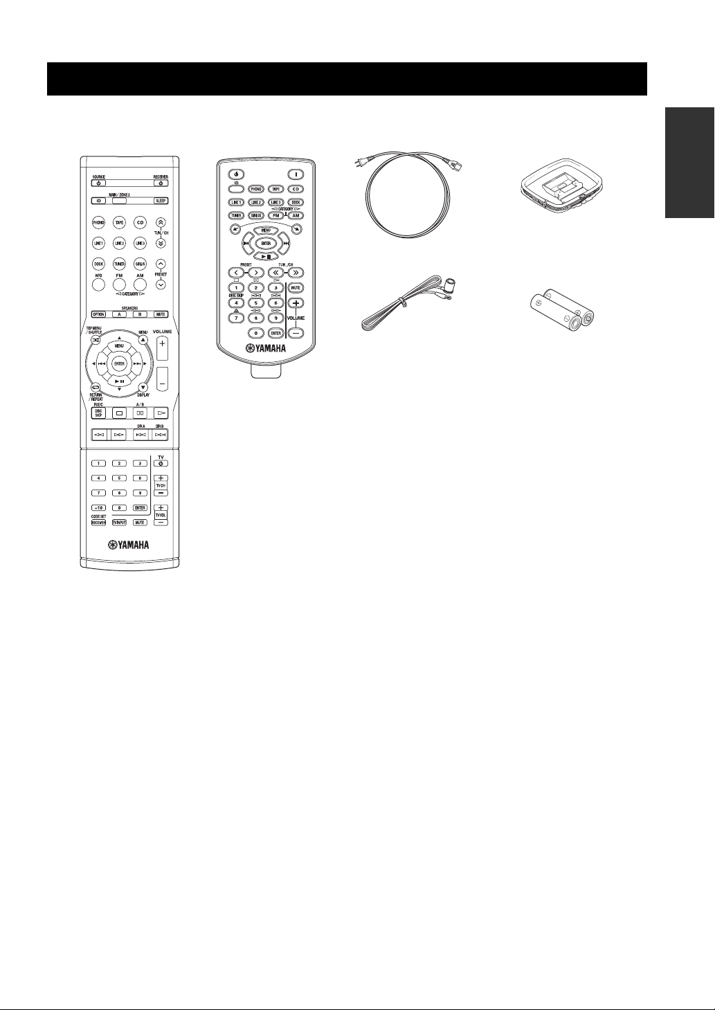
SUPPLIED ACCESSORIES
SUPPLIED ACCESSORIES
Please check that you received all of the following parts.
Remote control
Zone 2 remote control
(R-S700 only)
Power cable
(R-S700 only)
Indoor FM antenna
INTRODUCTION
AM loop antenna
Batteries (x2)
(AAA, R03, UM-4)
■ Notes on remote controls and batteries
• Do not spill water or other liquids on the remote control.
• Do not drop the remote control.
• Do not leave or store the remote control in the following conditions:
– places of high humidity, such as near a bath
– places of high temperatures, such as near a heater or stove
– places of extremely low temperatures
– dusty places
• Use AAA, R03, UM-4 batteries for the remote control.
• Use a CR2025 battery for the Zone 2 remote control (R-S700 only).
• Insert batteries according to the polarity markings (+ and -).
• Change all batteries if you notice the operation range of the remote control narrows.
• If the batteries run out, immediately remove them from the remote control to prevent an explosion or acid leak.
• If you find leaking batteries, discard the batteries immediately, taking care not to touch the leaked material. If the leaked material
comes into contact with your skin or gets into your eyes or mouth, rinse it away immediately and consult a doctor. Clean the battery
compartment thoroughly before installing new batteries.
• Do not use old batteries together with new ones. This may shorten the life of the new batteries or cause old batteries to leak.
• Do not use different types of batteries (such as alkaline and manganese batteries) together. Batteries that look the same may have a
different specification.
• Before inserting new batteries, wipe the battery compartment clean.
• Dispose of batteries according to your regional regulations.
3 En
CONTROLS AND FUNCTIONS
Front panel
CONTROLS AND FUNCTIONS
(R-S700)
y
indicates buttons and controls that can also be used to
control Zone 2. For more information about Zone 2, see pages 45
and 46.
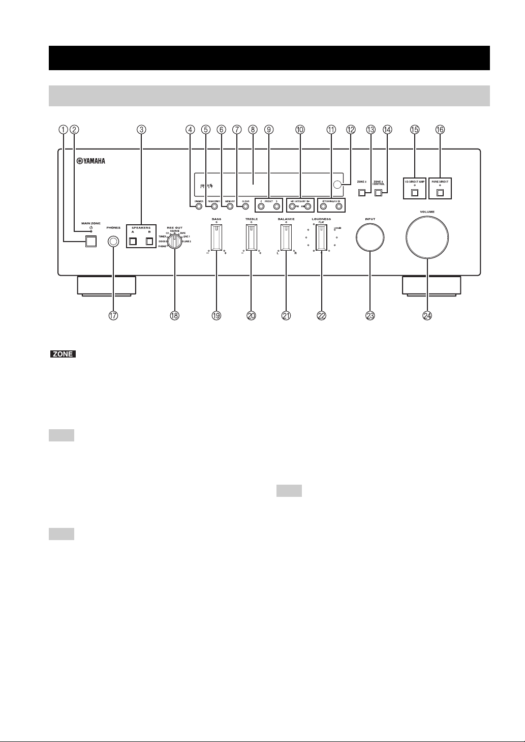
1 MAIN ZONE A
Turns on this unit’s Main Zone unit or sets the Main Zone
to standby mode (see page 16).
Note
In standby mode, this unit consumes a small amount of power to
receive infrared signals from the remote control.
2 MAIN ZONE indicator
Lights up as follows:
Brightly lit: Power is on
Dimly lit: Standby mode
Note
The MAIN ZONE indicator is brightly lit while an iPhone/iPod is
charging.
3 SPEAKERS A/B
Turns on or off the speaker set connected to the
SPEAKERS A and/or SPEAKERS B terminals on the rear
panel each time the corresponding button is pressed (see
page 16).
4 DIMMER
Changes the brightness level of the front panel display.
Choose brightness from 3 levels by pressing this button
repeatedly.
y
This setting is retained even if you turn off this unit.
5 FM MODE/INFO
Changes the FM radio wave reception mode (stereo or
monaural) when TUNER is selected as the input source
(see page 21).
Changes the SIRIUS Satellite Radio information
displayed on the front panel display when SIRIUS is
selected as the input source (see page 34).
Changes the playback information displayed about the
song playing on the iPhone/iPod when DOCK is selected
as the input source (see page 36).
Note
Playback information can only be displayed for an iPhone/iPod
that is connected using a Universal Dock for iPod.
6 MEMORY
Stores the current FM/AM station as a preset when
TUNER is selected as the input source (see page 23).
Stores the current SIRIUS channel as a preset when
SIRIUS is selected as the input source (see page 30).
7 CLEAR
Clears the current FM/AM preset station when TUNER is
selected as the input source (see page 24).
Clears the current SIRIUS preset channel when SIRIUS is
selected as the input source (see page 32).
8 Front panel display
Shows information about the operational status of this
unit.
4 En
CONTROLS AND FUNCTIONS
9 PRESET j / i
Selects a preset FM/AM station when TUNER is selected
as the input source (see page 24).
Selects a preset SIRIUS channel when SIRIUS is selected
as the input source (see page 31).
0 FM/CATEGORY l, AM/CATEGORY h
Sets the FM/AM tuner band to FM or AM when TUNER
is selected as the input source (see page 20).
Selects a channel category when SIRIUS is selected as the
input source (see page 29).
A TUNING/CH jj / ii
Selects the tuning frequency when TUNER is selected as
the input source (see page 20).
Searches for a SIRIUS channel when SIRIUS is selected
as the input source (see page 29).
B Remote control sensor
Receives infrared signals from the remote control.
Note
Switch the remote control ID between ID1 and ID2 when using
multiple Yamaha receivers or amplifiers (see page 44).
C ZONE 2
Turns on Zone 2 or sets ZONE 2 to standby mode. When
Zone 2 is turned on, signals are output to the ZONE 2
OUT jacks (see page 45).
D ZONE 2 CONTROL
Allows buttons and controls on the front panel to be used
to control Zone 2. For more information about controlling
Zone 2, see page 46.
E CD DIRECT AMP and indicator (R-S700 only)
Allows you to listen to a CD source in the purest possible
sound (see page 17). The indicator lights up and the front
panel display turns off when this function is turned on.
H REC OUT selector
Selects a source for recording to a CD recorder or to a tape
deck independently of the INPUT selector setting,
allowing you to record the selected source while listening
to another source (see page 19).
I BASS control
Increases or decreases the low frequency response. The
center position produces a flat response (see page 18).
J TREBLE control
Increases or decreases the high frequency response. The
center position produces a flat response (see page 18).
K BALANCE control
Adjusts the sound output balance of the left and right
speakers to compensate for sound imbalances caused by
speaker locations or listening room conditions (see page
18).
L LOUDNESS control
Retains a full tonal range at any volume level to
compensate for the human ears’ loss of sensitivity to high
and low-frequency ranges at a low volume level (see page
18).
M INPUT selector
Selects the input source you want to listen to.
N VOLUME control ( R-S700 only)
Increases or decreases the sound output level.
Note
This does not affect the output level of the REC jacks.
INTRODUCTION
Notes
• If both the CD DIRECT AMP and the PURE DIRECT are
turned on, only the CD DIRECT AMP will function.
• Zone 2 cannot be used while this function is turned on.
F PURE DIRECT and indicator
Allows you to listen to a source in the purest possible
sound (see page 17). The indicator above it lights up and
the front panel display turns off when this function is
turned on.
Note
Zone 2 cannot be used while this function is turned on.
G PHONES jack
Outputs audio to your headphones for private listening.
Note
Press SPEAKER A/B so that the SP A/B indicators turn off
before you connect your headphones to the PHONES jack.
5 En
CONTROLS AND FUNCTIONS
Front panel display
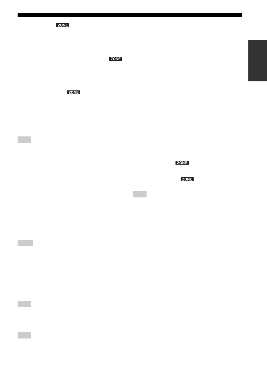
1 SP (SPEAKERS) A/B indicators
Light up according to the set of speakers selected.
Both indicators light up when both sets of speakers are
selected.
2 Input source indicators
Light up brightly to indicate the input source that is
currently selected.
3 PRESET indicator
Lights up when you recall a preset radio station or SIRIUS
channel. Blinks while the automatic station preset feature
is scanning for FM stations to register as presets.
4 MEMORY indicator
Lights up or blinks when an FM/AM station or SIRIUS
channel is being stored as a preset.
5 CATEGORY indicator
Lights up when searching for a SIRIUS channel by
category.
6 TUNED indicator
Lights up when this unit is tuned in to an FM or AM
station.
7 STEREO indicator
Lights up when this unit is receiving a strong signal for an
FM stereo broadcast.
8 HOLD indicator
Blinks when the hold function is used to display the artist
name, song title, etc. while listening to a SIRIUS channel.
B P indicator
Lights up when a preset number is selected. Blinks while
you are registering a preset radio station or SIRIUS
channel.
C Multi-information display
Shows information when adjusting or changing settings.
D Volume indicator
Displays the current volume level.
9 ZONE 2 indicator
Lights up when Zone 2 is turned on.
0 SLEEP indicator
Lights up when the sleep timer is turned on.
A MUTE indicator
Blinks while the MUTE function is turned on.
6 En
Rear panel
(R-S700)
CONTROLS AND FUNCTIONS
CONTROLS AND FUNCTIONS
INTRODUCTION
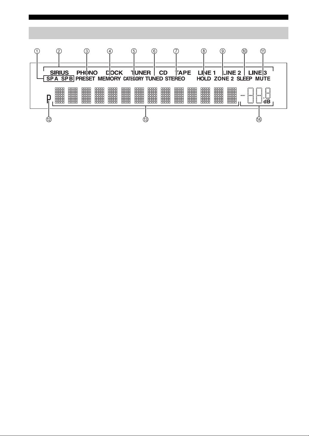
1 TRIGGER OUT jack (R-S700 only)
When this unit is turned on or when a certain input source
is selected, this unit can send a 12 V/100 mA direct
electric current via the TRIGGER OUT jack that can be
used to control an external component. The current is sent
according to the “Trigger out” setting in the Option menu
(see page 40).
Note
Do not connect a component that requires more than 100 mA of
electric current, otherwise the component may not perform
consistently or properly due to insufficient power.
2 REMOTE 2 IN jack (R-S700 only)
Used to receive remote control signals (see page 45).
3 REMOTE 1 IN/OUT jacks
Used to send and receive remote control signals (see page
45).
4 GND terminal
Used to connect a turntable (see page 12).
5 ZONE 2 OUT jacks
Used to connect a Zone 2 component (see page 45).
6 Antenna terminals
Used to connect FM and AM antennas (see page 14).
7 TAPE jacks
Used to connect a tape deck (see page 12).
8 DOCK jack
Used to connect an optional Yamaha Universal Dock for
iPod (such as the YDS-12), Wireless System for iPod
(YID-W10), or Bluetooth Wireless Audio Receiver
(YBA-10) (see page 35).
9 PHONO jacks
Used to connect a turntable (see page 12).
0 CD jacks
Used to connect a CD player (see page 12).
A LINE 1-3 jacks
Used to connect audio components (see page 12).
B iPod VIDEO output jack (R-S700 only)
Used to send iPhone/iPod video content to a video
monitor, such as a TV (see page 35).
Note
Video content output is possible only when an iPhone/iPod is
connected this unit using a Universal Dock for iPod (such as the
YDS-12).
C SIRIUS jack
Used to connect SiriusConnect tuner (sold separately) (see
page 27).
D COUPLER jacks (R-S700 only)
Used to connect an external unit (see page 15).
E SUBWOOFER OUT jack
Used to connect a subwoofer with built-in amplifier (see
page 12).
F POWER MANAGEMENT switch
Used to enable or disable the automatic power down
function. When this function is enabled, this unit’s Main
zone and Zone 2 automatically enters standby mode if this
unit is not operated for a certain amount of time (3 settings
are available; see page 43).
G SPEAKERS terminals
Used to connect speakers (see page 12).
H IMPEDANCE SELECTOR switch
Used to select the impedance setting (see page 13).
I AC IN (R-S700 only)
Used to plug in the supplied power cable (see page 15).
7 En
CONTROLS AND FUNCTIONS
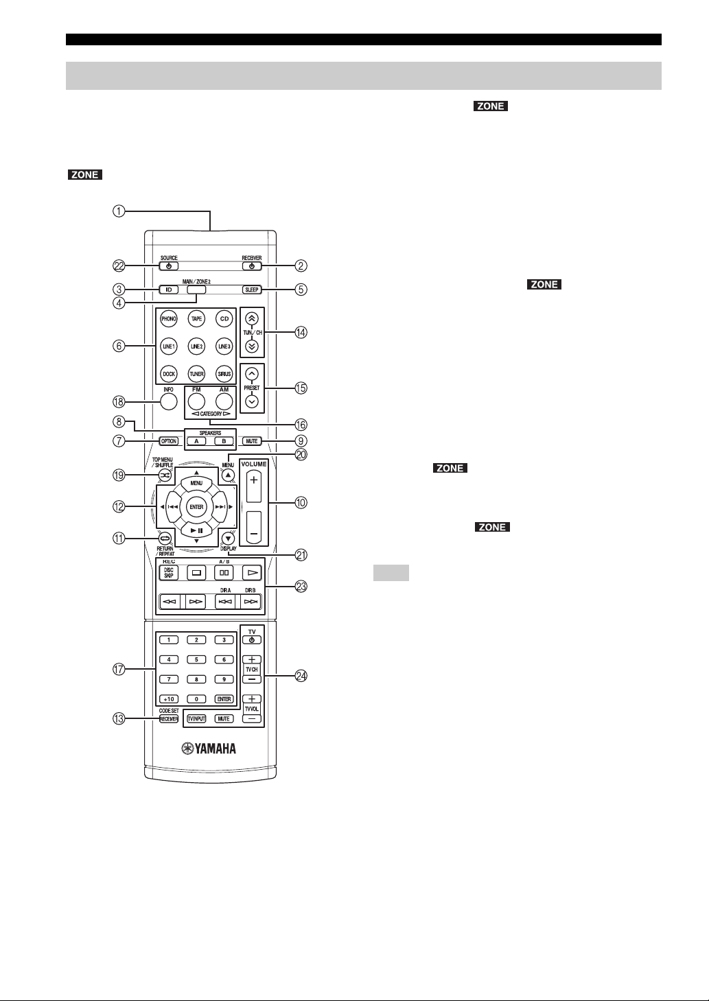
Remote control
This section describes the function of each button on the
remote control used to control this unit or other
components made by Yamaha or other manufacturers.
y
indicates buttons that can also be used to control Zone 2.
For more information about Zone 2, see pages 45 and 46.
2 RECEIVER A
Turns this unit on, or sets it to standby mode.
3 ID
Changes the remote control ID (see page 44).
4 MAIN/ZONE 2
Switches the zone to be operated by the remote control
between the Main Zone and Zone 2 (see page 46).
5 SLEEP
Sets the sleep timer (see page 19).
6 Input selector buttons
Selects the input source and changes the control area (see
page 47).
7 OPTION
Turns the OPTION menu on and off (see page 40).
8 SPEAKERS A/B
Turns on and off the set of speakers connected to the
SPEAKERS A and/or SPEAKERS B terminals on the rear
panel of this unit when the corresponding button is
pressed.
9 MUTE
Mutes the sound output. Press again to restore the sound
output to the previous volume level.
■ Common controls
The following buttons can be used no matter which input
source is selected.
1 Infrared signal transmitter
Sends infrared signals.
0 VOLUME +/– ( R-S700 only)
Increases or decreases the sound output level.
Note
This does not affect the output level of the REC jacks.
A RETURN
Returns to the previous menu or ends the menu display
when using the Option menu (see page 40).
B B / C / D / E / ENTER
Selects and confirms items in the Option menu (see page
40).
C CODE SET/RECEIVER
Used to program the remote control so that it can control
your other external components (see page 49).
After using the remote control to control one of your
components, this button is used to switch the remote
control to receiver mode so that remote control commands
will be sent to this unit (see page 48).
8 En

CONTROLS AND FUNCTIONS
■ SIRIUS and FM/AM controls
The following buttons can be used when SIRIUS or
TUNER is selected as the input source.
D TUN./CH H / I
Selects the tuning frequency when TUNER is selected as
the input source (see page 20).
Searches for a SIRIUS channel when SIRIUS is selected
as the input source (see page 29).
E PRESET F / G
Selects a preset FM/AM station when TUNER is selected
as the input source (see page 24).
Select a preset SIRIUS channel when SIRIUS is selected
as the input source (see page 31).
F FM/CATEGORY l, AM/CATEGORY h
Sets the FM/AM tuner band to FM or AM when TUNER
is selected as the input source (see page 20).
Selects a channel category when SIRIUS is selected as the
input source (see page 29).
G Numeric buttons, ENTER
Specifies the frequency or the preset number of the FM/
AM station when TUNER is selected as the input source
(see page 21).
Specifies the channel number or preset number of the
SIRIUS channel when SIRIUS is selected as the input
source (see page 30).
H INFO
Changes the SIRIUS Satellite Radio information
displayed on the front panel display when SIRIUS is
selected as the input source (see page 34).
■ External component controls
The following buttons can be used to control external
audio/video components when CD, TAPE, PHONO,
LINE1, LINE2, or LINE3 is selected as the input source.
For more information, see page 47.
A RETURN
B B / C / D / E / ENTER
G Numeric buttons, ENTER
I TOP MENU
J MENU
K DISPLAY
L SOURCE A
M External component control buttons
N TV control buttons
INTRODUCTION
■ iPod controls
The following buttons can be used when DOCK is
selected as the input source for listening to an iPhone/
iPod. For more information, see page 35.
A REPEAT
B MENU/ Ee / b / a / ENTER
H INFO
I SHUFFLE
J B
K C
9 En
CONTROLS AND FUNCTIONS
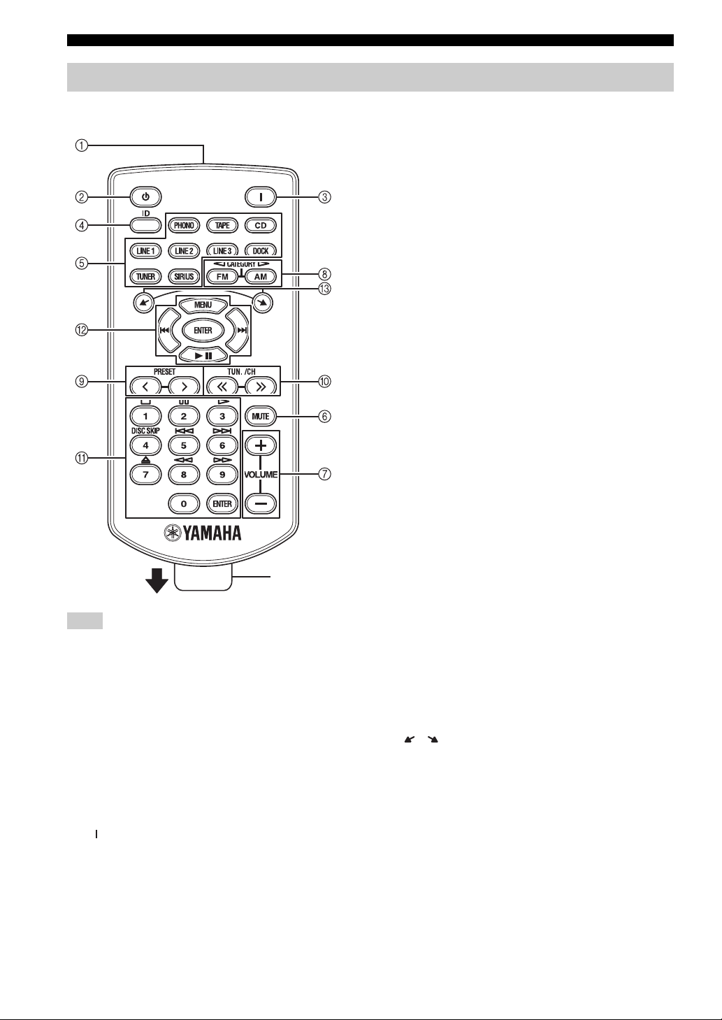
Zone 2 remote control (R-S700 only)
This section describes the function of each button on the
Zone 2 remote control, which is used to control Zone 2.
Insulation sheet
Note
The Zone 2 remote control comes with a battery already installed.
Before using the Zone 2 remote control for the very first time,
pull out the insulation sheet, as shown.
■ Common controls for Zone 2
The following buttons can be used no matter which input
source is selected for Zone 2.
1 Infrared signal transmitter
Sends infrared signals.
2 A (Zone 2 standby)
Sets Zone 2 to standby mode.
6 MUTE
Mutes the sound output to Zone 2. Press again to restore
the sound output to the previous volume level.
7 VOLUME +/–
Increases or decreases the sound output level of Zone 2.
■ SIRIUS and FM/AM controls
The following buttons can be used when SIRIUS or
TUNER is selected as the input source for Zone 2.
8 FM/CATEGORY l, AM/CATEGORY h
Sets the FM/AM tuner band to FM or AM when TUNER
is selected as the input source (see page 20).
Selects a channel category when SIRIUS is selected as the
input source (see page 29).
9 PRESET j / i
Selects a preset FM/AM station when TUNER is selected
as the input source (see page 24).
Selects a preset SIRIUS channel when SIRIUS is selected
as the input source (see page 31).
0 TUN./CH jj / ii
Selects the tuning frequency when TUNER is selected as
the input source (see page 20).
Searches for a SIRIUS channel when SIRIUS is selected
as the input source (see page 29).
A Numeric buttons, ENTER
Specifies the frequency or the preset number of the FM/
AM station when TUNER is selected as the input source
(see page 21).
Specifies the channel number or preset number of the
SIRIUS channel when SIRIUS is selected as the input
source (see page 30).
■ iPod controls
The following buttons can be used when DOCK is
selected as the input source for Zone 2, for listening to an
iPhone/iPod. For more information, see page 35.
B MENU/ Ee / b / a / ENTER
C /
3 (Zone 2 on)
Turns on Zone 2.
4 ID
Changes the Zone 2 remote control ID (see page 44).
5 Zone 2 input selector buttons
Selects the desired input source for Zone 2.
10 En
CONTROLS AND FUNCTIONS
■ Yamaha CD player controls
The following buttons can be used to control a Yamaha
CD player when CD is selected as the input source for
Zone 2.
A Yamaha CD player control buttons
• s Stops playback
• e Pauses playback
• p Starts playback
• DISC SKIP Skips to the next disc in a CD changer
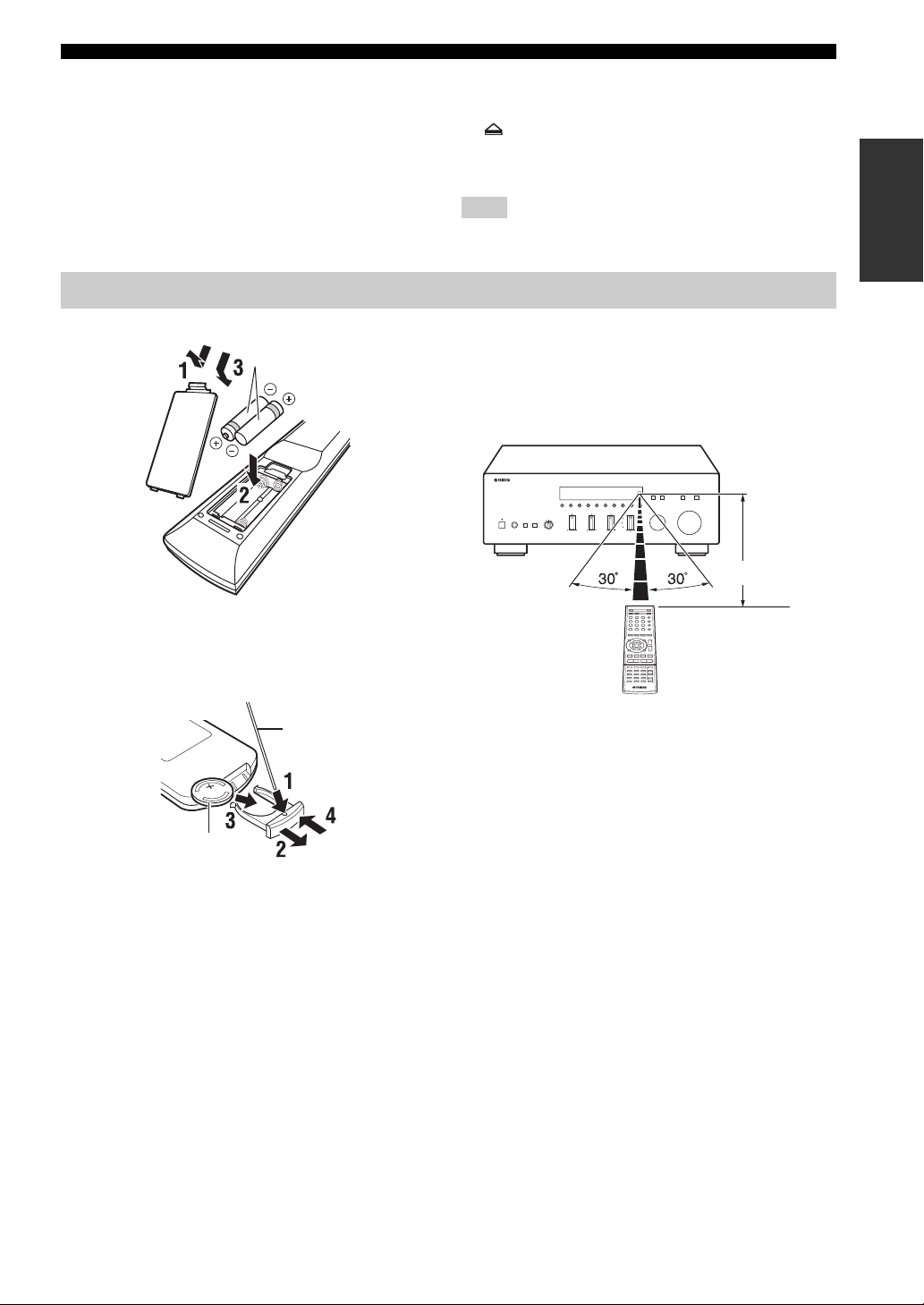
Using the remote controls
■ Installing batteries
AAA, R03, UM-4 batteries
• b Skips backward
• a Skips forward
• Ejects the disc
• w Rewinds playback
• f Fast-forwards playback
Note
Not all Yamaha CD players can be controlled by the Zone 2
remote control.
■ Operation range
The remote controls transmit a directional infrared beam.
Be sure to aim the remote controls directly at the remote
control sensor on the front panel of this unit or on the
infrared signal receiver in Zone 2 during operation.
Approximately
6 m (20 ft)
INTRODUCTION
■ Replacing the battery in the Zone 2
remote control
Change the battery when the operation range of the Zone 2
remote control decreases.
Straight pin
CR2025 battery
Remote control or Zone 2
remote control
11 En
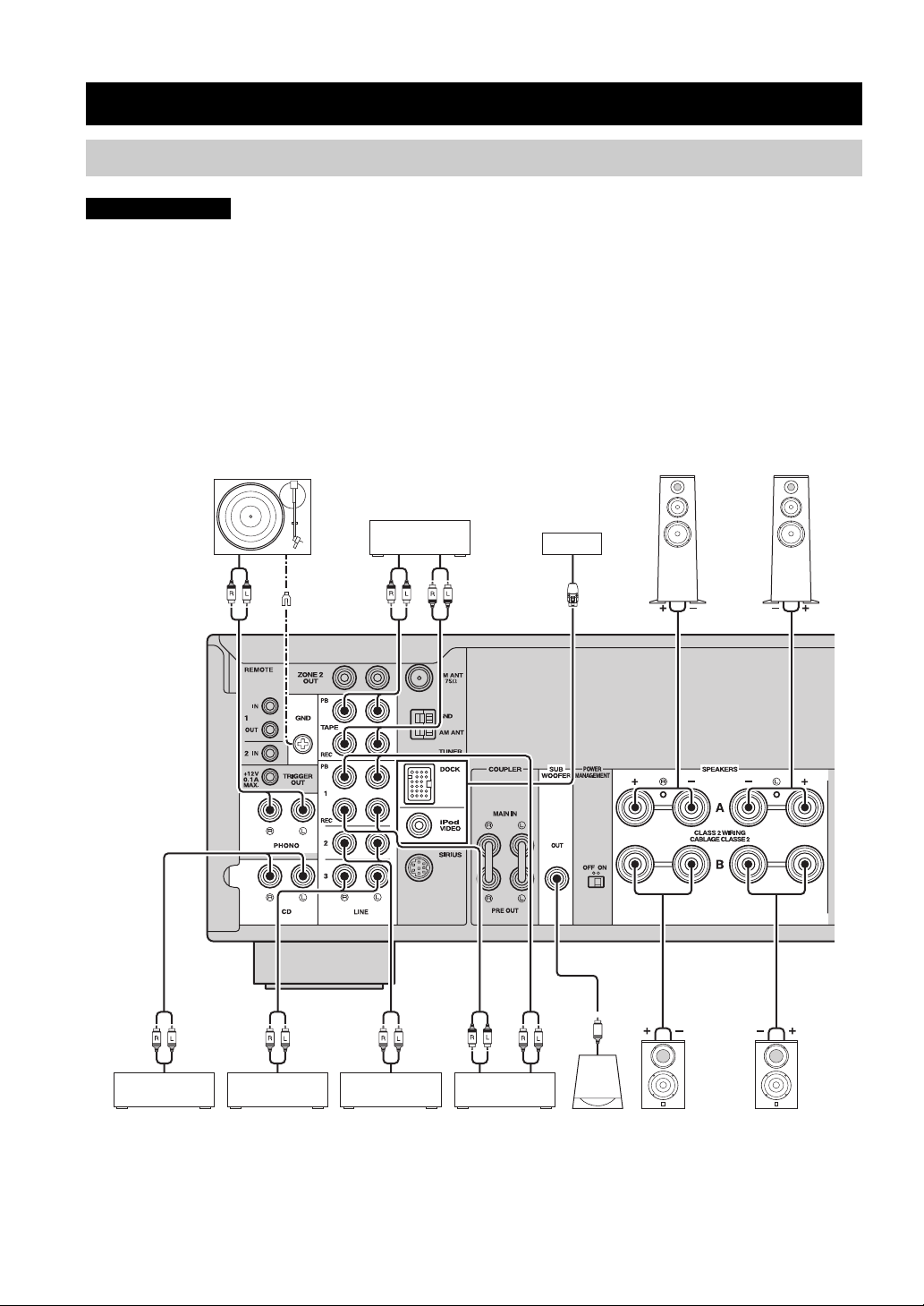
CONNECTIONS
CONNECTIONS
Connecting speakers and source components
CAUTION
• Do not connect this unit or other components to the main power until all connections between components are
complete.
• All connections must be correct: L (left) to L, R (right) to R, “+” to “+” and “–” to “–”. If the connections are faulty,
no sound will be heard from the speakers, and if the polarity of the speaker connections is incorrect, the sound will be
unnatural and lack bass. Refer to the owner’s manual for each of your components.
• Use RCA cables for audio components (except for speaker connections and DOCK jack connections).
• The IMPEDANCE SELECTOR must be set to the appropriate position before connecting speakers. See page 13 for
details.
• Do not let bare speaker wires touch each other or any metal part of this unit. This could damage this unit and/or the
speakers.
Audio
out
Turntable
GND
Audio
out
Tape deck
For information about
other components that
can be connected to
this unit, see page 35.
Audio
in
Speakers A
Audio
out
CD player
Audio
out
VCR, etc.
Audio
out
DVD player,
etc.
Audio
in
CD recorder,
etc.
Audio
out
Subwoofer
Speakers B
y
• The PHONO jacks are designed for connecting a turntable with an MM cartridge.
• Connect your turntable to the GND terminal to reduce noise in the signal. However, for some turntables, you may hear less noise
without the GND connection.
12 En
CONNECTIONS
■ IMPEDANCE SELECTOR switch
CAUTION
Do not change the IMPEDANCE SELECTOR switch
while the power of this unit is turned on, as doing so may
damage the unit.
If the unit fails to turn on, the IMPEDANCE SELECTOR
switch may not be fully slid to either position. If this is the
case, remove the power cable and slide the switch all the
way to either position.
Select the switch position (LOW or HIGH) according to
the impedance of the speakers in your system.
Switch
position
HIGH
LOW
• If you use one set (A or B), the impedance of
each speaker must be 6
or 8
• If you make bi-wire connections, the
impedance of each speaker must be 6
higher (R-S700) or 8
See page 13 for Bi-wire connection.
• If you use one set (A or B), the impedance of
each speaker must be 4
• If you use two sets (A and B) simultaneously,
the impedance of each speaker must be 8
higher.
• If you make bi-wire connections, the
impedance of each speaker must be 4
higher. See page 13 for Bi-wire connection.
Impedance level
Ω or higher (R-S700)
Ω or higher (R-S500).
Ω or
Ω or higher (R-S500).
Ω or higher.
Ω or
Ω or
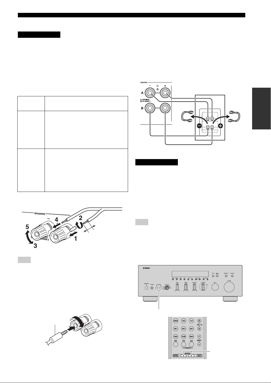
■ Connecting speaker cables
Remove
approximately
10 mm (3/8 in)
of insulation
from the end of
each speaker
cable.
Note
When inserting speaker cables into the speaker terminals, insert
only the bare speaker wire. If insulated cable is inserted, the
connection may be poor and sound may not be heard.
■ Bi-wire connection
Bi-wire connection separates the woofer from the
combined midrange and tweeter section. A bi-wire
compatible speaker has four binding post terminals. These
two sets of terminals allow the speaker to be split into two
independent sections. With these connections, the mid and
high frequency drivers are connected to one set of
terminals and the low frequency driver to another set of
terminals.
This unit
Speaker
Connect the other speaker to the other set of terminals in
the same way.
CAUTION
When making bi-wire connections, set the IMPEDANCE
SELECTOR switch to HIGH or LOW depending on the
impedance of your speakers:
6 Ω or higher: HIGH (R-S700)
8 Ω or higher: HIGH (R-S500)
4 Ω or higher: LOW
See page 13 for more information about the
IMPEDANCE SELECTOR switch.
Note
When making bi-wire connections, remove the shorting bridges
or cables on the speaker.
y
To use the bi-wire connections, press SPEAKERS A and
SPEAKERS B on the front panel or on the remote control so that
both SP A and B light up on the front panel display.
PREPARATION
■ Connecting via banana plug
Tighten the knob and then insert the banana plug into the
end of the corresponding terminal.
Banana plug
SPEAKERS A/B
SPEAKERS A/B
13 En
CONNECTIONS
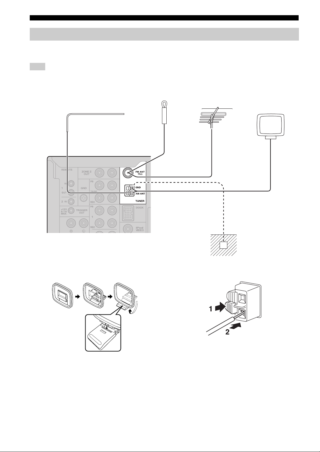
Connecting the FM and AM antennas
Indoor antennas for receiving FM and AM broadcasts are included with this unit. In general, these antennas should
provide sufficient signal strength. Connect each antenna correctly to the designated terminals.
Note
If you experience poor reception quality, install an outdoor antenna. Consult the nearest authorized Yamaha dealer or service center
about outdoor antennas.
Indoor FM antenna
(included)
Outdoor FM antenna
Outdoor AM antenna
Use 5 to 10 m of vinylcovered wire extended
outdoors from a window.
AM loop antenna
(included)
• The AM loop antenna
should always be connected,
even if an outdoor AM
antenna is connected to this
unit.
• The AM loop antenna
should be placed away from
this unit.
Ground (GND terminal)
For maximum safety and minimum interference, connect
the antenna GND terminal to a good earth ground. A
good earth ground is a metal stake driven into moist earth.
■ Assembling the supplied AM loop
antenna
■ Connecting the wire of the AM loop
antenna
14 En
CONNECTIONS
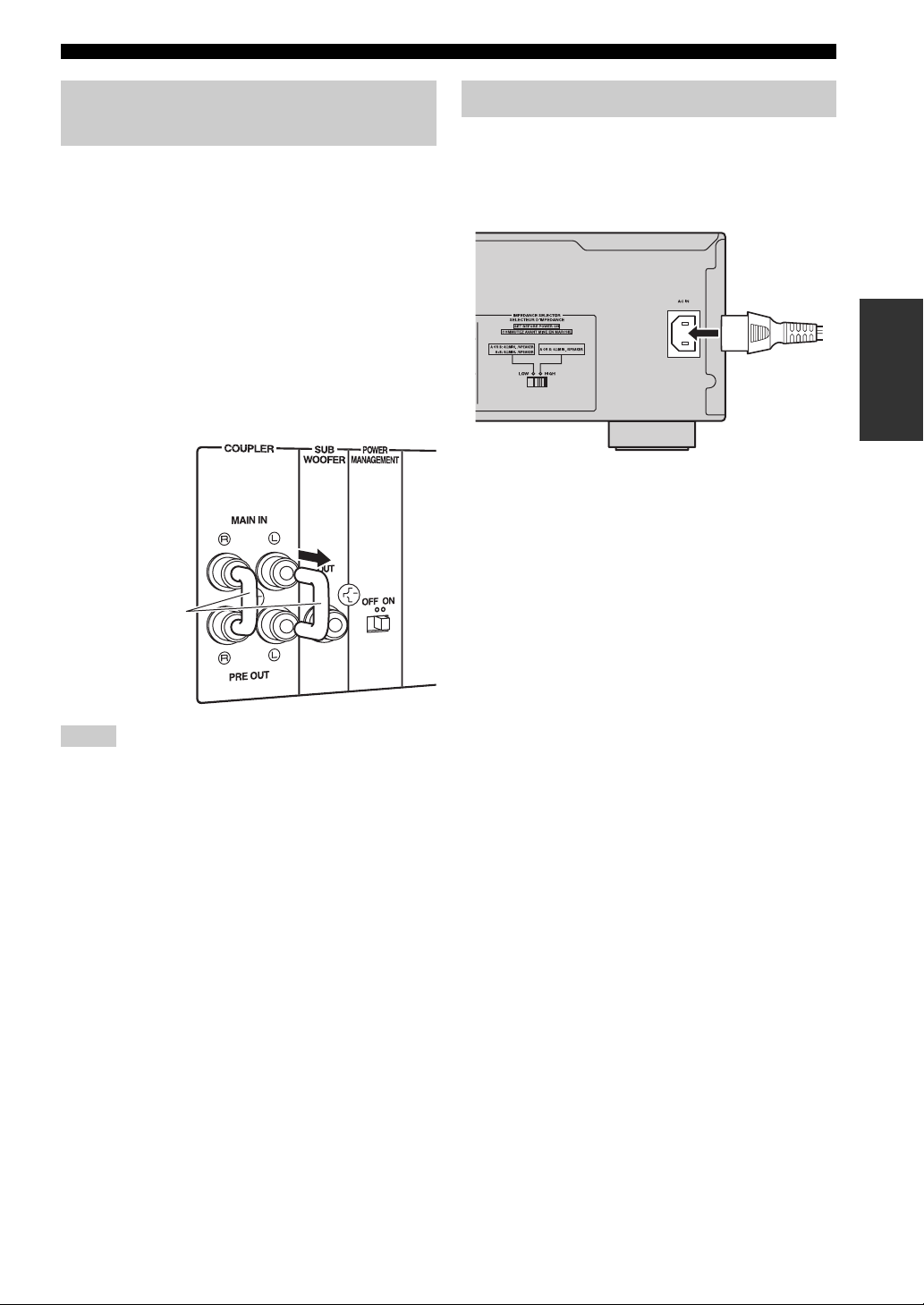
Using COUPLER jacks (R-S700 only)
Removing the jumper pins from the PRE OUT/MAIN IN
jacks enables this unit to operate separately as a control
amplifier or a power amplifier. These jacks are used to
connect a signal-processing system such as a graphic
equalizer or a surround-sound processor to this unit. If an
external unit is connected to these jacks, the VOLUME
control of this unit can be used to adjust the overall sound
output level.
To connect an external unit, first remove the jumper pins
from the PRE OUT/MAIN IN jacks and then connect the
input jacks of that external unit to the PRE OUT jacks or
its output jacks to the MAIN IN jacks. For details, refer to
the owner’s manual included with the external unit to be
connected.
Jumper pins
Connecting power cable
Plug the power cable into the AC IN on the rear panel of
this unit (R-S700 only).
Plug the power cable into the AC wall outlet after all other
connections are complete.
PREPARATION
Power cable
(R-S700 only)
Notes
• If you do not use the COUPLER jacks, never remove the
jumper pins from these jacks. If removed, no sound will be
output from this unit.
• Before installing or removing the jumper pins, be sure to
disconnect the power cable of the unit. Leaving the power cable
connected could cause noise to be emitted from the speakers or
damage the unit.
• When you use this unit as a power amplifier, connect the output
jacks of the external control amplifier, etc. to the MAIN IN
jacks of this unit. In this case, the controls of this unit will not
function except the PHONES jack and the SPEAKERS A/B
buttons. Use the controls on the external control amplifier to
make volume adjustments, etc.
15 En
PLAYING AND RECORDING
PLAYING AND RECORDING
CAUTION
Extreme caution should be exercised when you play back CDs encoded in DTS.
If you play back a CD encoded in DTS on a CD player that does not support DTS, only noise will be heard, and this noise
may damage your speakers. Check whether your CD player supports CDs encoded in DTS. Also, check the sound output
level of your CD player before you play back a CD encoded in DTS.
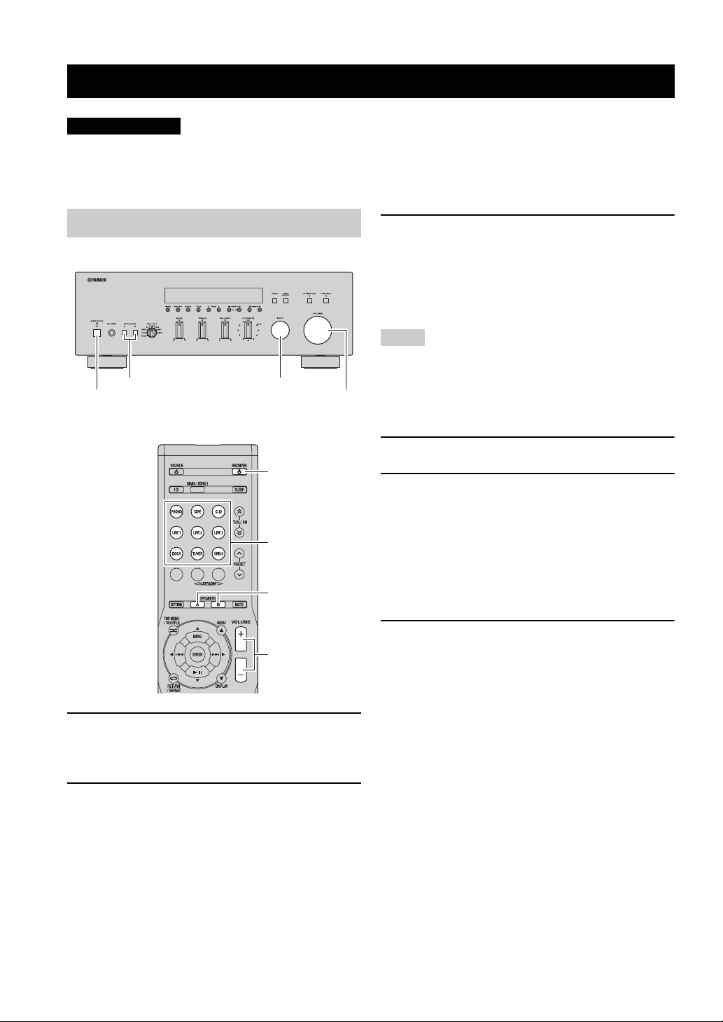
Playing a source
SPEAKERS A/B INPUT selector
MAIN ZONE A
VOLUME
RECEIVER A
Input selector
buttons
SPEAKERS A/B
3 Press SPEAKERS A and/or SPEAKERS B on
the front panel or on the remote control to
select speakers A and/or speakers B.
When speaker set A or speaker set B are turned on,
SP A or SP B is displayed on the front panel display
accordingly (see page 6).
Notes
• When one set of speakers is connected using bi-wire
connections, or when using two sets of speakers simultaneously
(A and B), make sure SP A and SP B are displayed on the front
panel display.
• When listening with headphones, turn off the speakers.
4 Play the source.
5 Rotate the VOLUME control on the front
panel (or press VOLUME +/– on the remote
control) to adjust the sound output level.
y
You can adjust the tonal quality by using the BASS, TREBLE,
BALANCE and LOUDNESS controls, the CD DIRECT AMP
switch (R-S700 only), or the PURE DIRECT switch on the front
panel (see page 17).
VOLUME +/–
1 Press MAIN ZONE A on the front panel (or
RECEIVER A on the remote control) to turn
on this unit.
2 Rotate the INPUT selector on the front panel
(or press one of the input selector buttons on
the remote control) to select the input source
you want to listen to.
16 En
6 Press MAIN ZONE A on the front panel again
(or RECEIVER A on the remote control) to
finish using this unit and set it to standby
mode.
Adjusting the tonal quality
■ Using the CD DIRECT AMP switch
(R-S700 only)
CD Direct Amp feature
Generates a normal phase and reverse phase signal for
both the left and right channels from the input signal
and uses the four electronic volumes to send a
balanced signal to the amplifying circuit. This feature
provides clearer sound as a result of:
• improved signal-to-noise ratio
• external noise canceling
• reduced distortion
Routes input signals from your CD player directly to the
specially built-in amplifier for the CD player. As a result,
the input signals bypass the INPUT selector and the
BASS, TREBLE, BALANCE and LOUDNESS controls
and then sent to the power amplifier, thus eliminating any
alterations to the CD signals and creating the purest
possible sound. The CD DIRECT AMP indicator lights up
and the front panel display turns off after a few seconds.
CD DIRECT AMP switch
PLAYING AND RECORDING
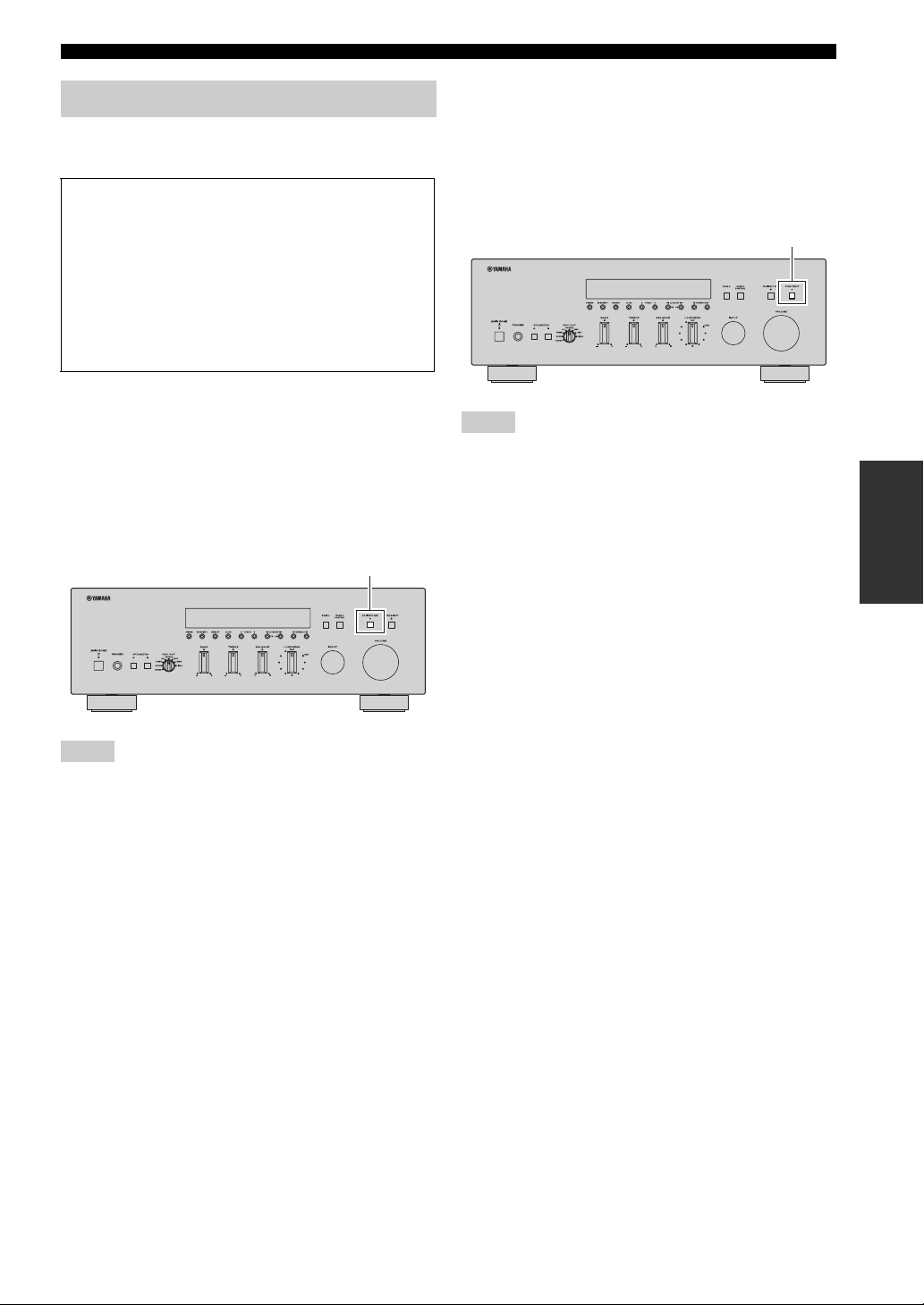
■ Using the PURE DIRECT switch
Routes input signals from your audio sources so that the
input signals bypass the BASS, TREBLE, BALANCE and
LOUDNESS controls, thus eliminating any alterations to
the audio signals and creating the purest possible sound.
The PURE DIRECT indicator lights up and the front panel
display turns off after a few seconds.
PURE DIRECT switch
Notes
• Zone 2 cannot be used while the PURE DIRECT feature is
turned on.
• The BASS, TREBLE, BALANCE, and LOUDNESS controls
do not function while the PURE DIRECT feature is turned on.
• This setting is retained even if you turn off this unit.
OPERATION
BASIC
Notes
• If both the CD DIRECT AMP and the PURE DIRECT switches
are turned on, only the CD DIRECT AMP switch will function.
• Zone 2 cannot be used while the CD DIRECT AMP feature is
turned on.
• The INPUT selector and the BASS, TREBLE, BALANCE, and
LOUDNESS controls do not function while the CD DIRECT
AMP feature is turned on.
• A CD player must be connected to the CD jacks in order to use
the CD DIRECT AMP feature.
• This setting is retained even if you turn off this unit.
17 En
PLAYING AND RECORDING
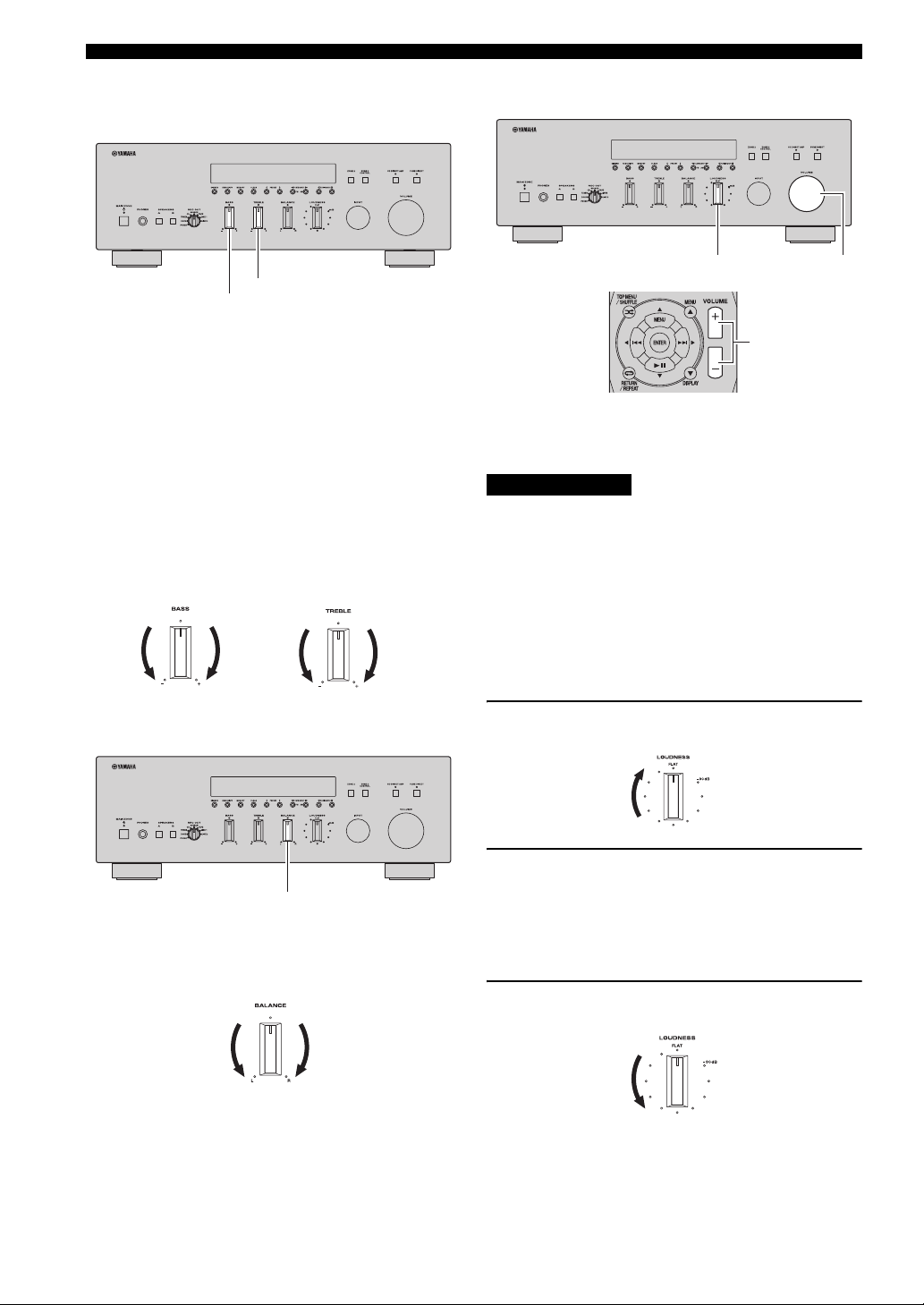
■ Adjusting the BASS and TREBLE
controls
TREBLE
BASS
The BASS and TREBLE controls adjust high and low
frequency response.
The center position produces a flat response.
BASS
When you feel there is not enough bass (low frequency
sound), rotate clockwise to boost. When you feel there is
too much bass, rotate counterclockwise to suppress.
Control range: –10 dB to +10 dB (20 Hz)
TREBLE
When you feel there is not enough treble (high frequency
sound), rotate clockwise to boost. When you feel there is
too much treble, rotate counterclockwise to suppress.
Control range: –10 dB to +10 dB (20 kHz)
■ Adjusting the LOUDNESS control
LOUDNESS VOLUME
VOLUME +/–
Retain a full tonal range at any volume level, thus
compensating for the human ears’ loss of sensitivity to
high and low-frequency ranges at low volume.
CAUTION
If the CD DIRECT AMP switch (R-S700 only) or the
PURE DIRECT switch is turned on with the LOUDNESS
control set at a certain level, the input signals bypass the
LOUDNESS control, resulting in a sudden increase in the
sound output level. To prevent your ears or the speakers
from being damaged, be sure to press the CD DIRECT
AMP switch (R-S700 only) or the PURE DIRECT switch
after lowering the sound output level or after checking that
the LOUDNESS control is properly set.
■ Adjusting the BALANCE control
BALANCE
The BALANCE control adjusts the sound output balance
of the left and right speakers to compensate for sound
imbalance caused by speaker locations or listening room
conditions.
1 Set the LOUDNESS control to the FLAT
position.
2 Rotate the VOLUME control on the front
panel (or press VOLUME +/– on the remote
control) to set the sound output level to the
loudest listening level that you would listen
to.
3 Rotate the LOUDNESS control until the
desired volume is obtained.
y
After setting the LOUDNESS control, enjoy listening to music at
your preferred volume level. If the effect of the LOUDNESS
control setting is too strong or weak, readjust the LOUDNESS
control.
18 En
 Loading...