

Yamaha R-N602 User Manual

Network Receiver
R-N602
Réseau Ampli-Tuner
G
OWNER’S MANUAL
MODE D’EMPLOI
BEDIENUNGSANLEITUNG
BRUKSANVISNING
MANUALE DI ISTRUZIONI
MANUAL DE INSTRUCCIONES
GEBRUIKSAANWIJZING
ИНСТРУКЦИЯ ПО ЭКСПЛУАТАЦИИ
English
Caution: Read this before operating your unit.
1 To assure the finest performance, please read this manual
carefully. Keep it in a safe place for future reference.
2 Install this sound system in a well ventilated, cool, dry, clean
place – away from direct sunlight, heat sources, vibration,
dust, moisture, and/or cold. For proper ventilation, allow the
following minimum clearances.
Top: 30 cm (11-3/4 in)
Rear: 20 cm (7-7/8 in)
Sides: 20 cm (7-7/8 in)
3 Locate this unit away from other electrical appliances, motors,
or transformers to avoid humming sounds.
4 Do not expose this unit to sudden temperature changes from
cold to hot, and do not locate this unit in an environment with
high humidity (i.e. a room with a humidifier) to prevent
condensation inside this unit, which may cause an electrical
shock, fire, damage to this unit, and/or personal injury.
5 Avoid installing this unit where foreign objects may fall onto
this unit and/or this unit may be exposed to liquid dripping or
splashing. On the top of this unit, do not place:
– Other components, as they may cause damage and/or
discoloration on the surface of this unit.
– Burning objects (i.e. candles), as they may cause fire,
damage to this unit, and/or personal injury.
– Containers with liquid in them, as they may fall and liquid
may cause electrical shock to the user and/or damage to
this unit.
6 Do not cover this unit with a newspaper, tablecloth, curtain,
etc. in order not to obstruct heat radiation. If the temperature
inside this unit rises, it may cause fire, damage to this unit,
and/or personal injury.
7 Do not plug in this unit to a wall outlet until all connections
are complete.
8 Do not operate this unit upside-down. It may overheat,
possibly causing damage.
9 Do not use force on switches, knobs and/or cords.
10 When disconnecting the power cable from the wall outlet,
grasp the plug; do not pull the cable.
11 Do not clean this unit with chemical solvents; this might
damage the finish. Use a clean, dry cloth.
12 Only voltage specified on this unit must be used. Using this
unit with a higher voltage than specified is dangerous and may
cause fire, damage to this unit, and/or personal injury. Yamaha
will not be held responsible for any damage resulting from use
of this unit with a voltage other than specified.
13 To prevent damage by lightning, keep the power cord
disconnected from a wall outlet or the unit during a lightning
storm.
14 Do not attempt to modify or fix this unit. Contact qualified
Yamaha service personnel when any service is needed. The
cabinet should never be opened for any reasons.
When not planning to use this unit for long periods of time (i.e.
15
vacation), disconnect the AC power plug from the wall outlet.
16 Be sure to read the “Troubleshooting” section in the owner’s
manual on common operating errors before concluding that
this unit is faulty.
17 Before moving this unit, press A downward to turn off this
unit and then disconnect the AC power plug from the AC wall
outlet.
18 Condensation will form when the surrounding temperature
changes suddenly. Disconnect the power cable from the
outlet, then leave this unit alone.
19 When using this unit for a long time, this unit may become
warm. Turn the system off, then leave this unit alone for
cooling.
20 Install this unit near the wall outlet and where the AC power
plug can be reached easily.
21 The batteries shall not be exposed to excessive heat such as
sunshine, fire or the like. When you dispose of batteries,
follow your regional regulations.
22 Excessive sound pressure from earphones and headphones
can cause hearing loss.
This unit is not disconnected from the AC power source as long as
it is connected to the wall outlet, even if this unit itself is turned off
by A. This state is called the standby mode. In this state, this unit is
designed to consume a very small quantity of power.
WARNING
TO REDUCE THE RISK OF FIRE OR ELECTRIC SHOCK, DO
NOT EXPOSE THIS UNIT TO RAIN OR MOISTURE.
Do not use this unit within 22 cm (9 inches) of persons with a heart
pacemaker implant or defibrillator implant.
This label is required to be attached to a product of which the
temperature of the top cover may be hot during operation.
i En

Caution: Read this before operating your unit.
■ Notes on remote controls and batteries
• Do not spill water or other liquids on the remote control.
• Do not drop the remote control.
• Do not leave or store the remote control in the following
conditions:
– places of high humidity, such as near a bath
– places of high temperatures, such as near a heater or stove
– places of extremely low temperatures
– dusty places
• Insert batteries according to the polarity markings (+ and -).
• Change all batteries if you notice the operation range of the
remote control narrows.
• If the batteries run out, immediately remove them from the
remote control to prevent an explosion or acid leak.
• If you find leaking batteries, discard the batteries
immediately, taking care not to touch the leaked material. If
the leaked material comes into contact with your skin or gets
into your eyes or mouth, rinse it away immediately and
consult a doctor. Clean the battery compartment thoroughly
before installing new batteries.
• Do not use old batteries together with new ones. This may
shorten the life of the new batteries or cause old batteries to
leak.
• Do not use different types of batteries (such as alkaline and
manganese batteries) together. Read the packaging carefully
as these different types of batteries may have the same shape
and color.
• Before inserting new batteries, wipe the battery compartment
clean.
• Keep the batteries in a location out of reach of children.
Batteries can be dangerous if a child were to put in his or her
mouth.
• If the batteries grow old, the effective operation range of the
remote control decreases considerably. If this happens,
replace the batteries with new one as soon as possible.
• If you plan not to use the unit for a long period of time,
remove the batteries from the unit. Otherwise, the batteries
will wear out, possibly resulting in a leakage of battery liquid
that may damage the unit.
• Do not throw away batteries with general house waste.
Dispose of them correctly in accordance with your local
regulations.
■ For U.K. customers
If the socket outlets in the home are not suitable for the plug
supplied with this appliance, it should be cut off and an
appropriate 3 pin plug fitted. For details, refer to the instructions
described below.
The plug severed from the mains lead must be destroyed, as a
plug with bared flexible cord is hazardous if engaged in a live
socket outlet.
■ Special Instructions for U.K. Model
IMPORTANT
THE WIRES IN MAINS LEAD ARE COLOURED IN
ACCORDANCE WITH THE FOLLOWING CODE:
Blue: NEUTRAL
Brown: LIVE
As the colours of the wires in the mains lead of this apparatus
may not correspond with the coloured markings identifying
the terminals in your plug, proceed as follows:
The wire which is coloured BLUE must be connected to the
terminal which is marked with the letter N or coloured
BLACK. The wire which is coloured BROWN must be
connected to the terminal which is marked with the letter L or
coloured RED.
Make sure that neither core is connected to the earth terminal
of the three pin plug.
ii En
English
Caution: Read this before operating your unit.
Information for Users on Collection and
Disposal of Old Equipment and Used Batteries
These symbols on the products, packaging, and/or
accompanying documents mean that used electrical
and electronic products and batteries should not be
mixed with general household waste.
For proper treatment, recovery and recycling of old
products and used batteries, please take them to
applicable collection points, in accordance with your
national legislation and the Directives 2002/96/EC
and 2006/66/EC.
By disposing of these products and batteries
correctly, you will help to save valuable resources
and prevent any potential negative effects on human
health and the environment which could otherwise
arise from inappropriate waste handling.
For more information about collection and recycling
of old products and batteries, please contact your
local municipality, your waste disposal service or the
point of sale where you purchased the items.
[Information on Disposal in other Countries
outside the European Union]
These symbols are only valid in the European Union.
If you wish to discard these items, please contact
your local authorities or dealer and ask for the
correct method of disposal.
Note for the battery symbol (bottom two
symbol examples):
This symbol might be used in combination with a
chemical symbol. In this case it complies with the
requirement set by the Directive for the chemical
involved.
We, Yamaha Music Europe GmbH hereby declare that this
unit is in compliance with the essential requirements and other
relevant provisions of Directive 1999/5/EC.
Yamaha Music Europe GmbH
Siemensstr. 22-34 25462 Rellingen, Germany
Tel: +49-4101-303-0
Bluetooth
• Bluetooth is a technology for wireless communication between
devices within an area of about 10 meters (33 ft) employing the
2.4 GHz frequency band, a band which can be used without a
license.
Handling Bluetooth communications
• The 2.4 GHz band used by Bluetooth compatible devices is a
radio band shared by many types of equipment. While
Bluetooth compatible devices use a technology minimizing the
influence of other components using the same radio band, such
influence may reduce the speed or distance of communications
and in some cases interrupt communications.
• The speed of signal transfer and the distance at which
communication is possible differs according to the distance
between the communicating devices, the presence of obstacles,
radio wave conditions and the type of equipment.
• Yamaha does not guarantee all wireless connections between
this unit and devices compatible with Bluetooth function.
iii En

Contents
INTRODUCTION
What you can do with this unit ................................. 2
Sources that can be played back on this unit ................. 2
Mastering useful apps (MusicCast CONTROLLER).... 3
Supplied accessories ................................................... 4
Controls and functions ............................................... 5
Front panel ..................................................................... 5
Front display .................................................................. 7
Rear panel ...................................................................... 8
Remote control............................................................... 9
PREPARATION
Connections ............................................................... 11
Connecting the speakers .............................................. 12
Connecting the FM and AM antennas ......................... 13
Connecting the network cable ..................................... 14
Preparing a wireless antenna ....................................... 14
Connecting power cable .............................................. 14
Connecting to network ............................................. 15
Sharing the iOS device setting..................................... 16
Using the WPS push button configuration .................. 17
Set the wireless network connection manually............ 18
Connecting a mobile device to the unit directly
(Wireless Direct) ..................................................... 19
Verify the network connection status .......................... 20
BASIC OPERATION
Playback .................................................................... 21
Playing a source........................................................... 21
Using the sleep timer ................................................... 23
Listening to FM/AM radio....................................... 24
FM/AM tuning............................................................. 24
Automatic preset tuning (FM stations only)................ 24
Manual tuning preset ................................................... 25
Recalling a preset station ............................................. 26
Clearing a preset station............................................... 26
Radio Data System tuning ........................................... 27
Playing back music via Bluetooth............................ 28
Connecting a Bluetooth device (pairing) ..................... 28
Playing back Bluetooth device contents ...................... 28
Disconnecting a Bluetooth connection ........................ 29
Playing back music stored on media servers
(PCs/NAS) ............................................................. 30
Setting the media sharing of music files ...................... 30
Playback of PC music contents.................................... 31
Listening to Internet radio .......................................33
Registering favorite Internet radio stations
(bookmarks)............................................................. 34
Playing back iPod/iTunes music via a network
(AirPlay).................................................................35
Playback of iPod/iTunes music contents ..................... 35
Playing back music stored on a USB storage
device ......................................................................37
Connecting a USB storage device ............................... 37
Playback of USB storage device contents ................... 37
Playing back iPod music ...........................................39
Connecting an iPod...................................................... 39
Playback of iPod content ............................................. 39
Switching information on the front display............41
Registering the current playback song/station
(Preset function) ....................................................42
Registering to a preset ................................................. 42
Recalling a preset......................................................... 42
ADVANCED OPERATION
Configuring playback settings for different
playback sources (Option menu) .........................43
Option menu items....................................................... 43
Configuring various functions (Setup menu) .........44
Setup menu items......................................................... 44
Network ....................................................................... 45
Bluetooth ..................................................................... 46
Max Volume ................................................................ 47
Initial Volume.............................................................. 47
AutoPowerStdby (Auto Power Standby)..................... 47
ECO Mode................................................................... 47
Configuring the system settings
(ADVANCED SETUP menu)...............................48
ADVANCED SETUP menu items .............................. 48
Changing the speaker impedance setting (SP IMP.) ... 48
Selecting the remote control ID (REMOTE ID).......... 48
Restoring the default settings (INIT) ........................... 48
Updating the firmware (UPDATE) ............................. 49
Checking the firmware version (VERSION)............... 49
Updating the unit’s firmware via the network.......50
ADDITIONAL INFORMATION
Troubleshooting.........................................................51
Error indications on the front display.....................57
Trademarks ...............................................................58
Specifications .............................................................59
Index...........................................................................60
PREPARATIONINTRODUCTION
OPERATION
BASIC
OPERATION
ADVANCED
INFORMATION
ADDITIONAL
• “Note” indicates precautions for use of the unit and its feature limitations. y indicates supplementary explanations for better use.
• This manual explains operations using the supplied remote control.
• This manual describes all the “iPod” and “iPhone” as the “iPod”. “iPod” refers to “iPod” and “iPhone”, unless otherwise specified.
• In this manual, iOS and Android mobile devices are collectively referred to as “mobile devices”. The specific type of mobile
device is noted in explanations as needed.
1 En
English
INTRODUCTION
FM/AMFM/AM
VOLUME
PURE DIRECT
RETURN
CONNECT
PUSH - ENTER
TUNINGPRESET
BAND
MEMORY CLEAR
BASSINPUT
5V
1A
BALANCE
LR
TREBLE
LOUDNESS
FLAT
-30dB
DIMMER
DISPLAY
SELECT
PHONES
SPEAKERS
AB
MODE
This unit
1 Internet
2 Streaming service
Modem
Router*
3 PC
5 AirPlay (iTunes)
4 NAS
7 iPod
0
5 AirPlay (iPod)
6 Bluetooth
8 USB
device
9 CD player etc.
Mobile
device
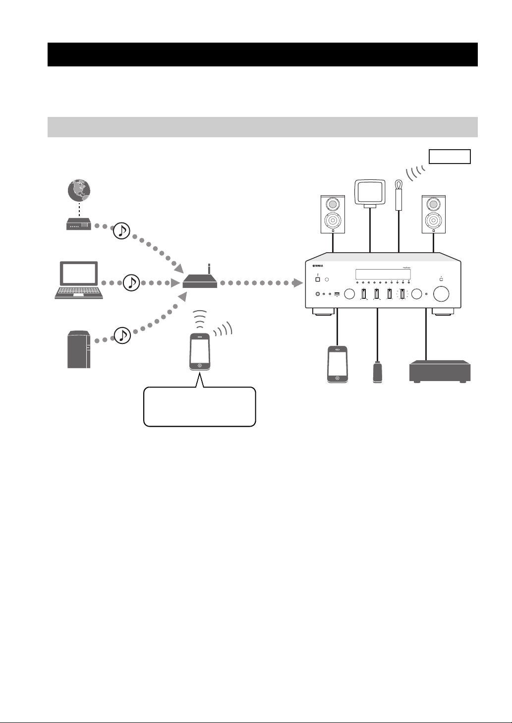
What you can do with this unit
This unit is a network receiver compatible with a network source such as a media server and mobile device.
It supports playback from not only analog sources such as a CD player but also Bluetooth devices and network streaming
services.
Sources that can be played back on this unit
*
You need a commercially available wireless router (access point) when you use a mobile device.
1 Play back the Internet radio (p. 33)
2 Play back the streaming service
(see the supplement for each service.)
3 Play back music files stored on your PC (p. 30)
4 Play back music files stored on your NAS
(p. 30)
5 Play back music files stored on your iPod/
iTunes with AirPlay (p. 35)
y
For details on connecting the external devices, see “Connections” (p. 11).
2 En
6 Play back audio content from Bluetooth
devices (p. 28)
7 Play back music files stored on your iPod
(p. 39)
8 Play back music files stored on your USB
device (p. 37)
9 Play back your external component (p. 11)
0 Listening to FM/AM radio (p. 24)

Mastering useful apps (MusicCast CONTROLLER)
What you can do with this unit
You can operate and program the unit, or play streaming services via this unit, by installing the free dedicated MusicCast
CONTROLLER app on a mobile device. For details, search for “MusicCast CONTROLLER” on the App Store or
Google Play.
■ MusicCast CONTROLLER capabilities
• Basic operations of the unit (turn on/standby, adjust volume and select input)
• Play songs stored on computers (servers)
• Select an Internet radio station
• Play music stored on mobile devices
• Play music on streaming service
• Distribute and receive audio between the unit and other Yamaha MusicCast supported devices
See MusicCast Setup Guide for details.
INTRODUCTION
3 En
English
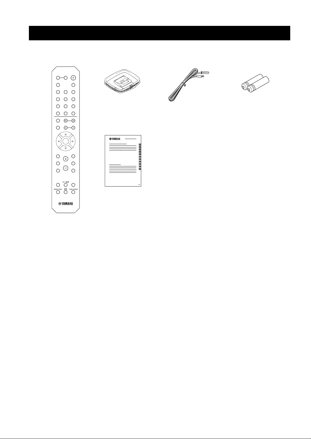
Supplied accessories
LINE 1
OPT 1 OPT 2 CD
COAX 1 COAX 2
BLUETOOTH
NET USB
LINE 2 LINE 3
TUNER
PRESET
TUNING
BAND
MEMORY
SETUP
HOME
MUTENOW PLAYING
VOLUME
RETURN
ENTER
REPEAT
SHUFFLE
SLEEP
PHONO
B
A
SPEAKERS
OPTION
Remote control
FM antennaAM antenna
Batteries (x2)
(AA, R6, UM-3)
MusicCast Setup Guide
Check that the following accessories are supplied with the product.
4 En
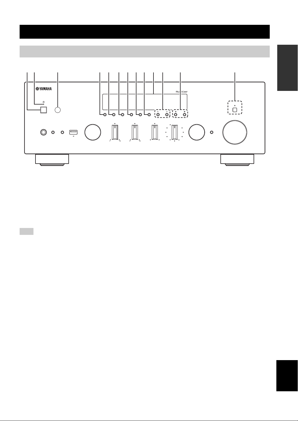
Front panel
VOLUME
PURE DIRECT
RETURN
CONNECT
PUSH - ENTER
TUNINGPRESET
BAND
MEMORY CLEAR
BASSINPUT
5V
1A
BALANCE
LR
TREBLE
LOUDNESS
FLAT
-30dB
DIMMER MODE
DISPLAY
SELECT
PHONES
SPEAKERS
AB
12 3 4 5 6 7 8 9: B CA
Controls and functions
Controls and functions
INTRODUCTION
1 A (power)
Turns on/off (standby) the unit.
2 STANDBY/ON indicator
Lights up as follows:
Brightly lit: Power is on
Dimly lit: Standby mode
Note
In standby mode, this unit consumes a small amount of power to
receive infrared signals from the remote control.
3 Remote control sensor
Receives infrared signals from the remote control.
4 DIMMER
Changes the brightness level of the front display. Choose
brightness from 5 levels by pressing this button
repeatedly.
5 DISPLAY
Selects the information displayed on the front display
(p. 41).
6 MODE
Sets the FM band reception mode to automatic stereo or
monaural (p. 24).
Switches the iPod operation modes (p. 40).
7 MEMORY
Registers the current FM/AM station as a preset when
TUNER is selected as the input source (p. 25).
Registers the current playback song or streaming station
as a preset when NET, USB (except iPod) are selected as
the input source (p. 42).
8 CLEAR
Clears a FM/AM preset station when TUNER is selected
as the input source (p. 26).
9 BAND
Switches between FM and AM (p. 24).
0 Front display
Shows information about the operational status of this
unit.
A PRESET j / i
Recalls a preset FM/AM station (p. 26) or song/streaming
station (p. 42).
B TUNING jj / ii
Selects the tuning frequency when TUNER is selected as
the input source (p. 24).
C PURE DIRECT and indicator
Allows you to listen to a source in the purest possible
sound (p. 21). The indicator above it lights up and the
front display turns off when this function is turned on.
English
5 En
Controls and functions
VOLUME
PURE DIRECT
RETURN
CONNECT
PUSH - ENTER
TUNINGPRESET
BAND
MEMORY CLEAR
BASSINPUT
5V
1A
BALANCE
LR
TREBLE
LOUDNESS
FLAT
-30dB
DIMMER MODE
DISPLAY
SELECT
PHONES
SPEAKERS
AB
NIHGED J KLMF
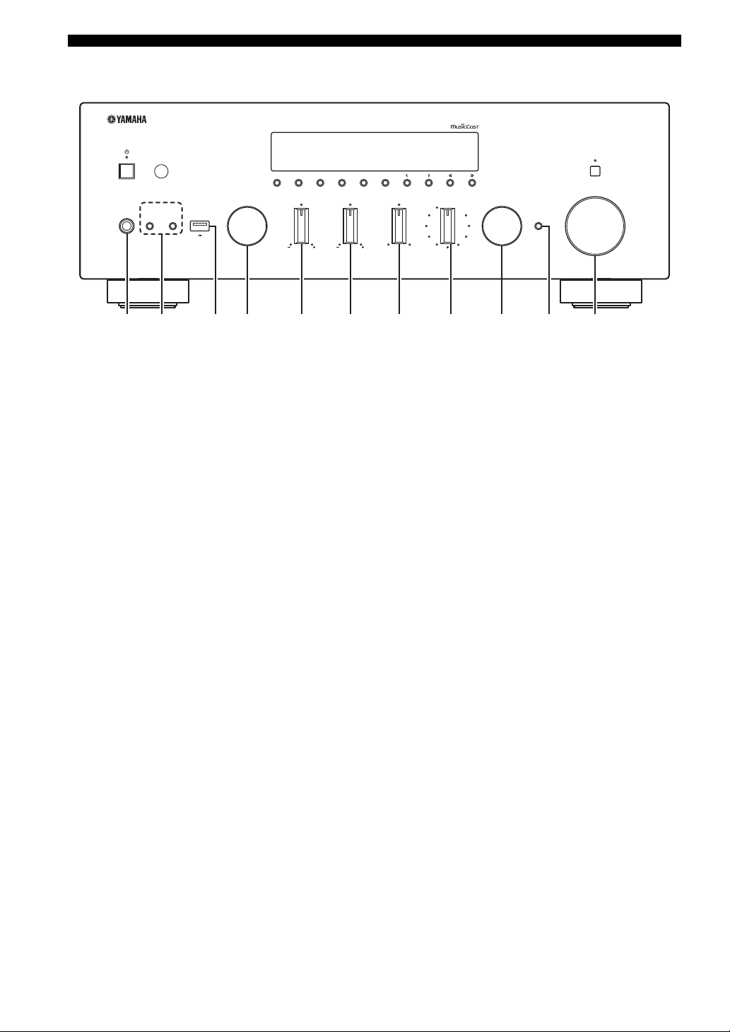
D PHONES jack
Outputs audio to your headphones for private listening.
E SPEAKERS A/B
Turns on or off the speaker set connected to the
SPEAKERS A and/or SPEAKERS B terminals on the rear
panel each time the corresponding button is pressed.
F USB jack
For connecting a USB storage device (p. 37) or an iPod
(p. 39).
G INPUT selector
Selects the input source you want to listen to.
H BASS +/– control
Increases or decreases the low frequency response. The
center position produces a flat response (p. 22).
I TREBLE +/– control
Increases or decreases the high frequency response. The
center position produces a flat response (p. 22).
J BALANCE control
Adjusts the sound output balance of the left and right
speakers to compensate for sound imbalances caused by
speaker locations or listening room conditions (p. 22).
K LOUDNESS control
Retains a full tonal range at any volume level to
compensate for the human ears’ loss of sensitivity to high
and low-frequency ranges at a low volume level (p. 22).
L SELECT/ENTER (jog dial)
Turn the dial to select a numeric value or setting, and press
the dial to confirm.
M RETURN
Returns to the previous indication of the front display.
CONNECT
Use to control the unit using the dedicated MusicCast
CONTROLLER app for mobile devices. See MusicCast
Setup Guide for details.
N VOLUME control
Increases or decreases the sound output level.
6 En

Controls and functions
VOL.
MUTE
TUNEDSTEREO
A
SLEEP
B
1 9
6
: :
2
3 7 854
Front display
y
If the network connection is not set, turn the power ON to display “WAC” (Wireless Accessory Configuration) on the front panel and
trigger an automatic iOS device search. See “Sharing the iOS device setting” (p. 16) for details on the iOS device and network
connection.
INTRODUCTION
1 Information display
Displays the current status (such as input name).
You can switch the information that is displayed when you
press DISPLAY on the front panel (p. 41).
2 STEREO
Lights up when the unit is receiving a stereo FM radio
signal.
3 TUNED
Lights up when the unit is receiving an FM/AM radio
station signal.
4 Signal strength indicator
Lights up when the unit connects to a wireless network or
operates as an access point. The strength of the wireless
network signal can be verified by the indicator status.
5 Bluetooth indicator
Lights up when the unit is connecting to a Bluetooth
device.
6 Speaker indicators
“A” lights up when the SPEAKERS A output is enabled
and “B” lights up when the SPEAKERS B output is
enabled.
7 SLEEP
Lights up when the sleep timer is on.
8 MUTE
Blinks when audio is muted.
9 Volume indicator
Indicates the current volume.
0 Cursor indicators
Indicate the remote control cursor keys currently
operational.
y
You can change the brightness level of the front display by
pressing DIMMER on the front panel (p. 5).
English
7 En
Controls and functions
A
B
SPEAKERS
NETWORK
COAXIAL
OPTICAL
FM AM
75Ω
ANTENNA
SUBWOOFER
PRE OUT
PHONO
IN
1
IN
OUT
2
1
2
1
2
IN
CD
LINE
OUT
3
SIGNAL
GND
3 5 68
A
1 2 4 7
9 :
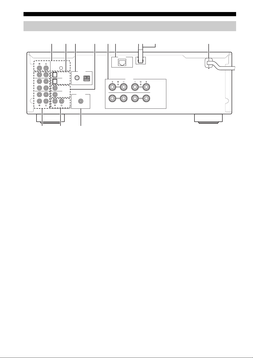
Rear panel
1 PHONO jacks
For connecting to a turntable (p. 11).
2 OPTICAL 1/2 jacks
For connecting to audio components equipped with
optical digital output (p. 11).
3 ANTENNA terminals
For connecting to FM and AM antennas (p. 13).
4 COAXIAL 1/2 jacks
For connecting to audio components equipped with a
coaxial digital output (p. 11).
5 SPEAKERS terminals
Used to connect speakers (p. 12).
6 NETWORK jack
For connecting to a network with a network cable (p. 14).
7 Wireless antenna
For connecting to a network device wirelessly (p. 14).
8 Power cable
For connecting to an AC wall outlet (p. 14).
9 LINE 1-3 jacks
For connecting to analog audio components (
p. 11
).
0 CD jacks
For connecting to a CD player (p. 11).
A SUBWOOFER PRE OUT jack
For connecting to a subwoofer with built-in amplifier
(p. 11).
8 En
Remote control
1
3
6
7
0
8
9
2
4
5
A
Controls and functions
SPEAKERS
B
A
PHONO
COAX 1 COAX 2
OPT 1 OPT 2 CD
LINE 1
LINE 2 LINE 3
TUNER
NET USB
BAND
MEMORY
HOME
SETUP
REPEAT
TUNING
PRESET
ENTER
VOLUME
SLEEP
BLUETOOTH
RETURN
OPTION
MUTENOW PLAYING
SHUFFLE
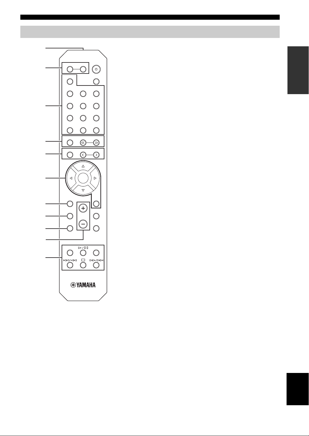
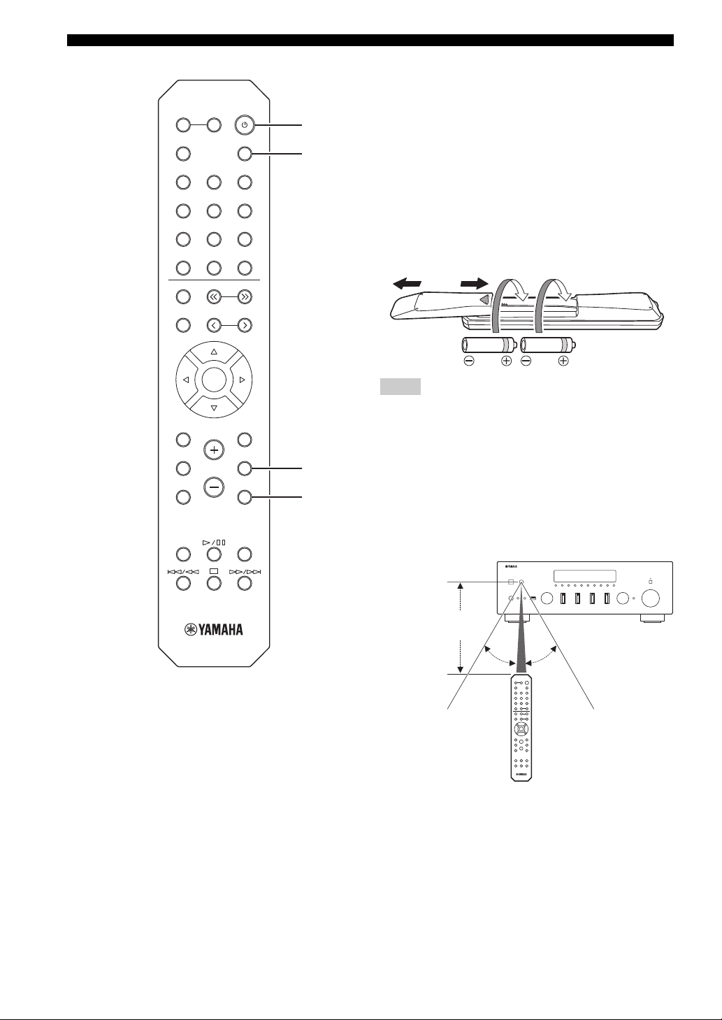
1 Infrared signal transmitter
Sends infrared signals.
2 SPEAKERS A/B
Turns on and off the set of speakers connected to the SPEAKERS
A and/or SPEAKERS B terminals on the rear panel of this unit
when the corresponding key is pressed.
3 Input selection keys
Select an input source for playback.
PHONO PHONO jacks
COAX 1/2 COAXIAL1/2 jacks
BLUETOOTH Bluetooth connection
OPT 1/2 OPTICAL 1/2 jacks
CD CD jacks
LINE 1-3 LINE 1-3 jacks
TUNER FM/AM tuner
NET Network source (press repeatedly to select a
desired network source)
USB USB jack (on the front panel)
4 Radio keys
Operate the FM/AM radio (p. 24).
BAND Switches between FM and AM.
TUNING jj/ii Selects the radio frequency.
5 Preset keys
MEMORY Registers the current FM/AM station as a
preset when TUNER is selected as the input
source (p. 25).
Registers the current playback song or
streaming station as a preset when NET, USB
(except iPod) are selected as the input source
(p. 42).
PRESET j/i Recalls a preset FM/AM station (p. 26) or
song/streaming station (p. 42).
6 Menu operation keys
Cursor keys Select a menu or a parameter.
(B/C/D/E)
ENTER Confirms a selected item.
RETURN Returns to the previous state.
7 HOME
Moves up top level when selecting music files, folders, etc.
8 SETUP
Displays the “Setup” menu (p. 44).
9 NOW PLAYING
Displays music information when selecting music files, folders,
etc.
0 VOLUME +/-
Adjust the volume.
A Playback keys
Let you play back and perform other operations for network
sources, Bluetooth devices and USB devices.
INTRODUCTION
English
9 En
Controls and functions
30° 30°
Remote control
Approximately
6 m (20 ft)
SPEAKERS
B
A
PHONO
COAX 1 COAX 2
OPT 1 OPT 2 CD
LINE 1
LINE 2 LINE 3
SLEEP
BLUETOOTH
B
C
B A (power)
Turns on/off (standby) the unit.
C SLEEP
Sets the sleep timer (p. 23).
D OPTION
Displays the “Option” menu (p. 43).
E MUTE
Mutes the audio output.
TUNER
BAND
MEMORY
HOME
SETUP
REPEAT
NET USB
TUNING
PRESET
ENTER
VOLUME
RETURN
OPTION
MUTENOW PLAYING
SHUFFLE
D
E
■ Installing batteries
13
2
Notes
• Change all batteries if the operation range of the remote control
narrows.
• Before inserting new batteries, wipe the compartment clean.
■ Operation range
The remote controls transmit a directional infrared beam.
Be sure to aim the remote controls directly at the remote
control sensor on the front panel of this unit.
10 En
PREPARATION
A
B
SPEAKERS
NETWORK
COAXIAL
OPTICAL
FM AM
75Ω
ANTENNA
SUBWOOFER
PRE OUT
PHONO
IN
1
IN
OUT
2
1
2
1
2
IN
CD
LINE
OUT
3
SIGNAL
GND
O C
Audio
input
Audio
output
Speakers B
Turntable
Audio
output
DVD player, etc.
GND
Audio output
(digital coaxial)
Audio output
(digital optical)
CD player, etc.
Audio
output
CD player
Subwoofer
CD recorder, etc.
Speakers A
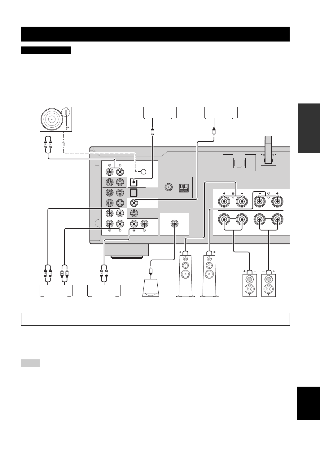
Connections
CAUTION
• Do not connect this unit or other components to the main power until all connections between components are complete.
• All connections must be correct: L (left) to L, R (right) to R, “+” to “+” and “–” to “–”. If the connections are faulty,
no sound will be heard from the speakers, and if the polarity of the speaker connections is incorrect, the sound will be
unnatural and lack bass. Refer to the owner’s manual for each of your components.
• Do not let bare speaker wires touch each other or any metal part of this unit. This could damage this unit and/or the speakers.
• Make sure to use RCA cables, optical cables to connect audio components.
PREPARATION
Only PCM signals can be input to the digital (OPTICAL/COAXIAL) jacks of this unit.
y
• The PHONO jacks are designed for connecting a turntable with an MM cartridge.
• Connect your turntable to the GND terminal to reduce noise in the signal. However, for some turntables, you may hear less noise
without the GND connection.
Notes
• In order to prevent the audio signal from looping when an audio recording device is connected, the audio signal is not output from the
LINE 2 (OUT) jacks when LINE 2 is selected. Similarly, the audio signal is not output from the LINE 3 (OUT) jacks when LINE 3 is
selected.
• Do not bundle audio cables and speaker cables together with the power cable. Doing so may generate noise.
English
11 En
Connections
aa
b
b
d
d
c
c
10 mm
(3/8")
This unit
Speaker
VOLUME
PURE DIRECT
RETURN
CONNECT
PUSH - ENTER
TUNINGPRESET
BAND
MEMORY CLEAR
BASSINPUT
5V
1A
BALANCE
LR
TREBLE
LOUDNESS
FLAT
-30dB
DIMMER MODE
DISPLAY
SELECT
PHONES
SPEAKERS
AB
SPEAKERS A/B
OPT 1 OPT 2 CD
COAX 1 COAX 2
BLUETOOTH
SLEEP
PHONO
B
A
SPEAKERS
SPEAKERS A/B
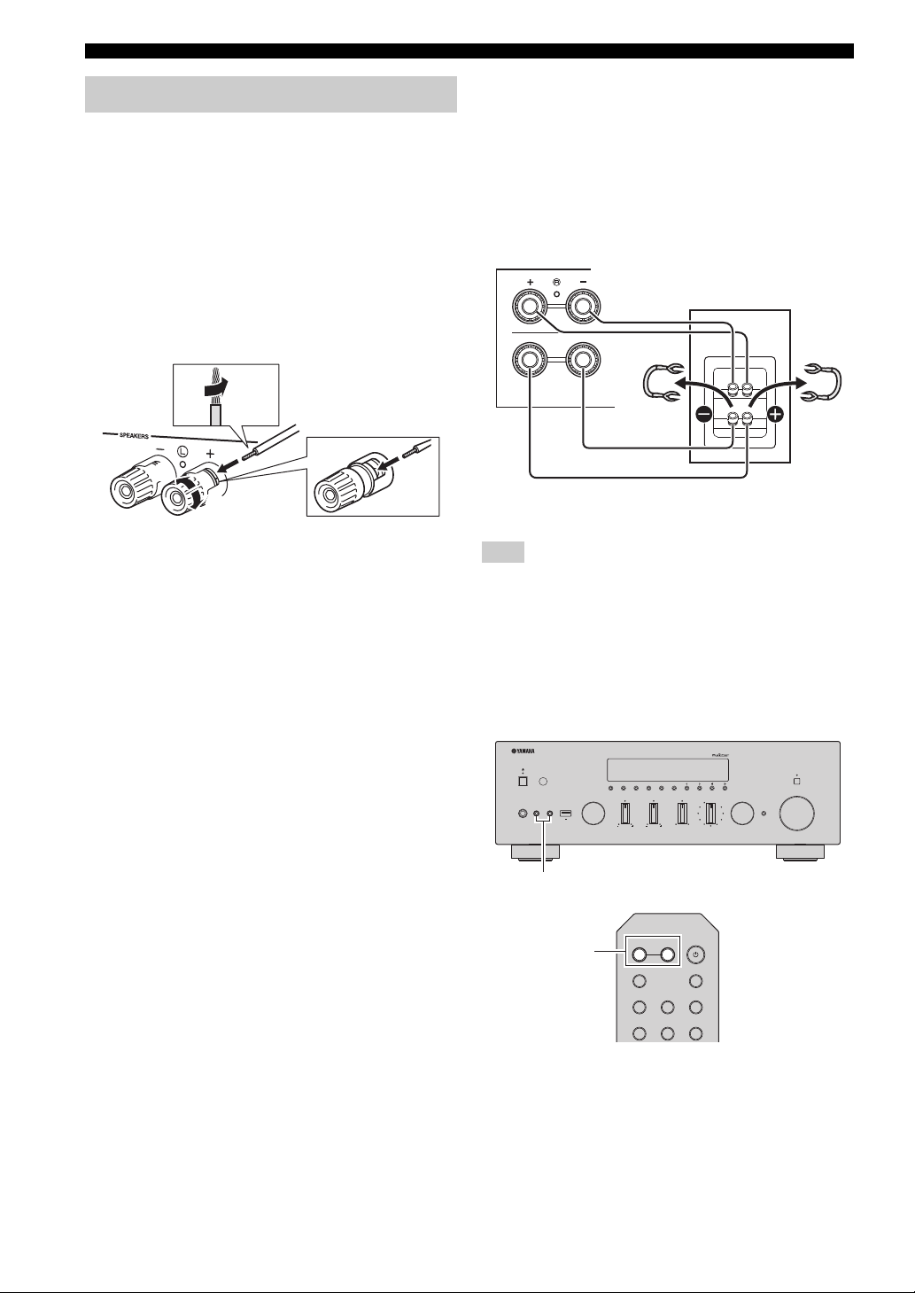
Connecting the speakers
■ Connecting speaker cables
Speaker cables have two wires. One is for connecting the
negative (–) terminal of the unit and the speaker, and the
other is for the positive (+) terminal. If the wires are
colored to prevent confusion, connect the black wire to the
negative and the other wire to the positive terminal.
a
Remove approximately 10 mm (3/8”) of insulation from the ends of
the speaker cable and twist the bare wires of the cable firmly together.
b Loosen the speaker terminal.
c Insert the bare wires of the cable into the gap on the side (upper
right or bottom left) of the terminal.
d Tighten the terminal.
■ Bi-wire connection
Bi-wire connection separates the woofer from the
combined midrange and tweeter section. A bi-wire
compatible speaker has four binding post terminals. These
two sets of terminals allow the speaker to be split into two
independent sections. With these connections, the mid and
high frequency drivers are connected to one set of terminals
and the low frequency driver to another set of terminals.
SPEAK
A
B
Connect the other speaker to the other set of terminals in
the same way.
Note
When making bi-wire connections, remove the shorting bridges
or cables on the speaker. Refer to the speakers’ instruction
manuals for more information.
y
To use the bi-wire connections, press SPEAKERS A and
SPEAKERS B on the front panel or on the remote control so that
both speaker indicators (“A” and “B”) light up on the front
display.
12 En
Connections
COAXIAL
OPTICAL
FM AM
75Ω
ANTENNA
SUBWOOFER
PRE OUT
PHONO
IN
1
IN
OUT
2
1
2
1
2
IN
CD
LINE
OUT
3
SIGNAL
GND
FM antenna
(included)
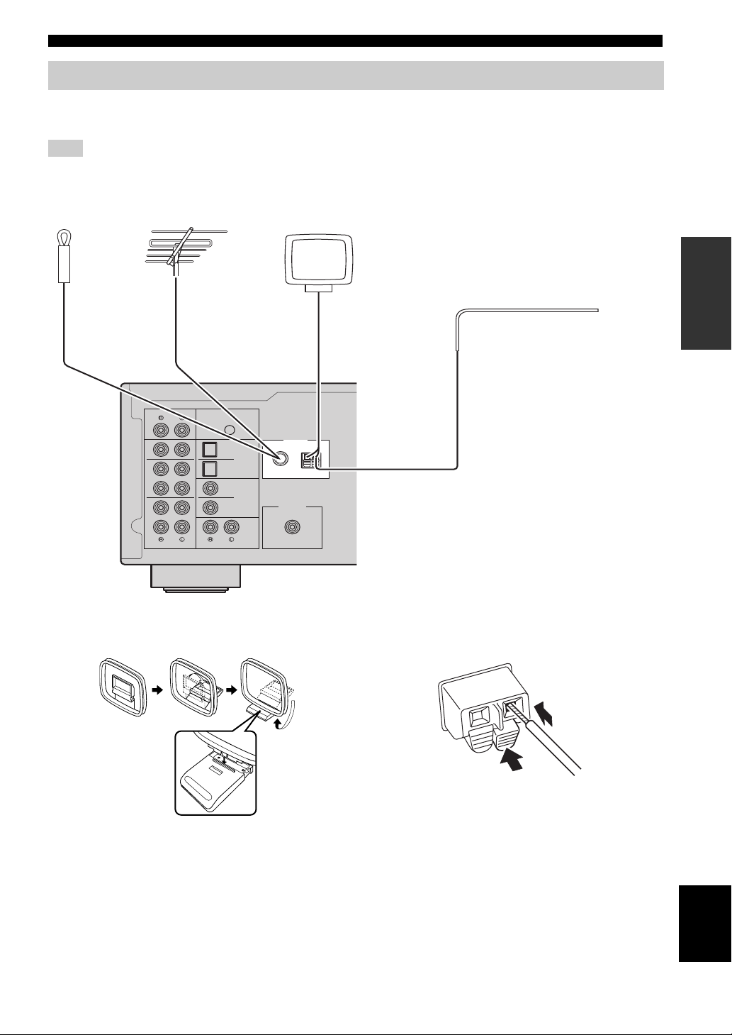
Outdoor AM antenna
Use 5 to 10 m of vinyl-covered wire extended
outdoors from a window.
Outdoor
FM antenna
• The AM antenna should always be connected, even if an outdoor
AM antenna is connected to this unit.
• The AM antenna should be placed away from this unit.
AM antenna (included)
or
Insert
2
Hold down
1
Connecting the FM and AM antennas
The antennas for receiving FM and AM broadcasts are included with this unit. In general, these antennas should provide
sufficient signal strength. Connect each antenna correctly to the designated terminals.
Note
If you experience poor reception quality, install an outdoor antenna. Consult the nearest authorized Yamaha dealer or service center
about outdoor antennas.
PREPARATION
■ Assembling the supplied AM antenna ■ Connecting the wires of the AM antenna
English
13 En
Connections
Network Attached Storage
(NAS)
Internet
Modem
Router
Network cable
PC
This unit (rear)
Mobile device
(such as iPhone)
WIRELES
S
WORK
To an AC wall outlet
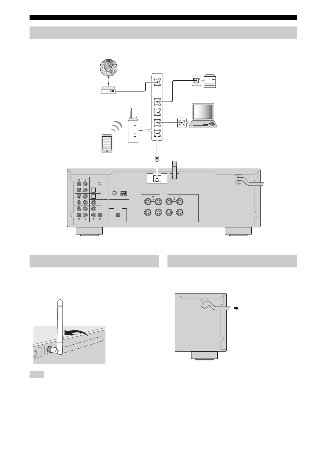
Connecting the network cable
Connect the unit to your router with a commercially-available STP network cable (CAT-5 or higher straight cable).
WAN
LAN
PHONO
IN
1
IN
2
OUT
IN
3
OUT
SIGNAL
GND
ANTENNA
FM AM
1
OPTICAL
2
75Ω
1
COAXIAL
SUBWOOFER
2
PRE OUT
LINE
CD
Preparing a wireless antenna
If you connect the unit wirelessly, erect the wireless
antenna. For information on how to connect the unit to a
wireless network, see “Connecting to network” (p. 15).
NETWORK
SPEAKERS
A
B
Connecting power cable
After all the connections are complete, plug in the power
cable.
Note
Do not apply excessive force on the wireless antenna. Doing so
may damage the antenna.
14 En
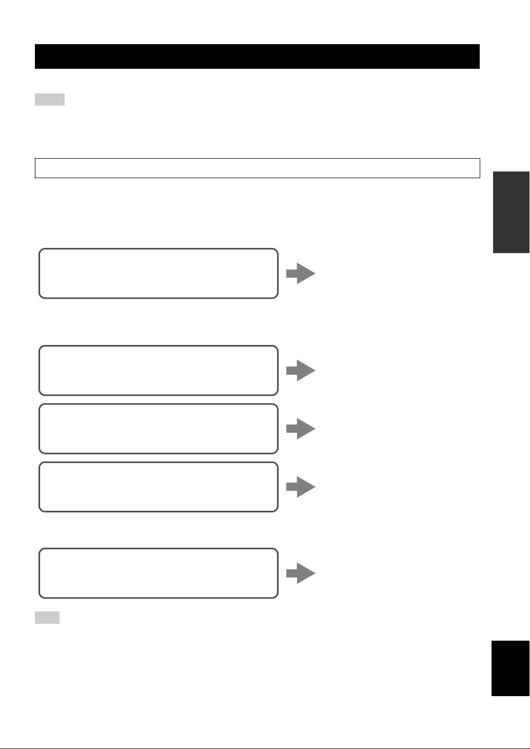
Connecting to network
Connecting using the DHCP server function of the
router
You can connect to the network by
simply making a wired connection
(p. 14)
Connecting using the Wi-Fi setting of the iOS
device (iPhone / iPod touch)
Share the Wi-Fi setting of the iOS
device (p. 16)
Connecting using WPS push button configuration
on the wireless router (or access point)
Use the WPS push button
configuration (p. 17)
Connecting with a wireless router (access point)
without WPS push button configuration
Set the network connection
manually (p. 18)
Connecting wirelessly to a mobile device
(Wireless Direct)
Connect wirelessly with Wireless
Direct (p. 19)
Connecting to network
There are several methods to connect the unit to a network. Select a connection method according to your environment.
Notes
• Some security software installed on your PC or the firewall settings of network devices (such as a router) may block the access of the
unit to the network devices or the Internet. In these cases, configure the security software or firewall settings appropriately.
• Each server must be connected to the same subnet as the unit.
• To use the service via the Internet, broadband connection is strongly recommended.
When playing a high-resolution audio source via the network, we recommend connecting with a wired router for stable playback.
■ Connecting with the MusicCast CONTROLLER app
See MusicCast Setup Guide for details.
■ Connecting with the wired router
■ Connecting with a wireless router (access point)
Connect to the network with the method listed below that corresponds to your environment.
PREPARATION
■ Connecting without a wired router or wireless router (access point)
Note
When the unit is connected to the network with Wireless Direct, it cannot connect to any other wireless router (access point). To play
back contents from the Internet, connect this unit to a network with a wired router or wireless router (access point).
English
15 En
Connecting to network
RETURN
SETUP
ENTER
Cursor keys B /
C
Wireless(WAC)
SHARE
The name of this unit
Tap here to start setup
The network currently
selected
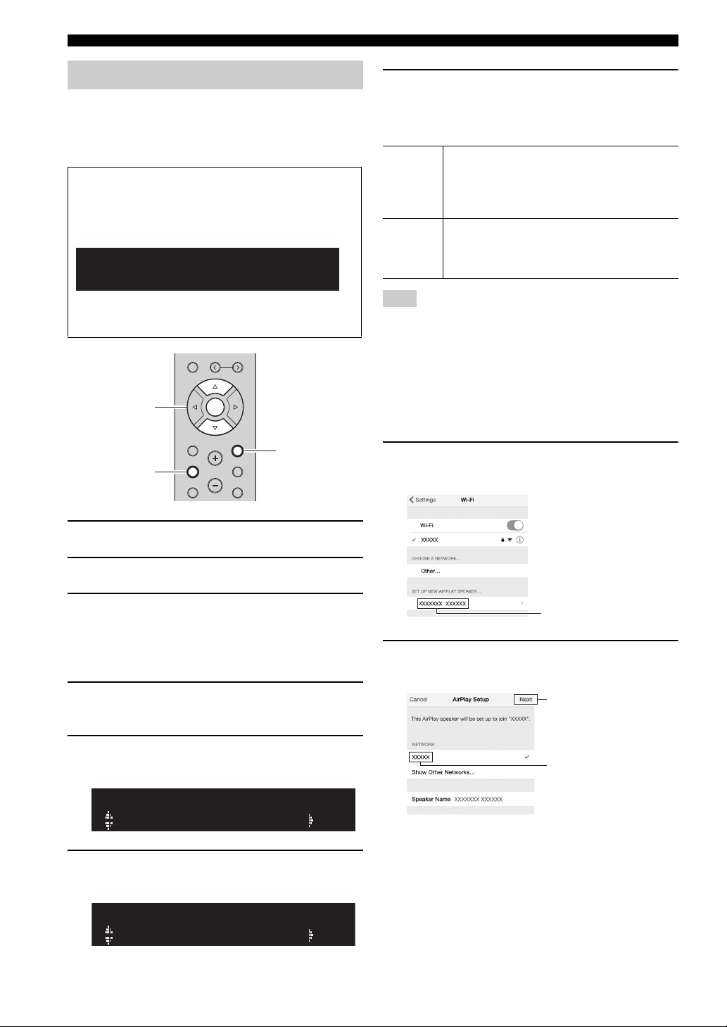
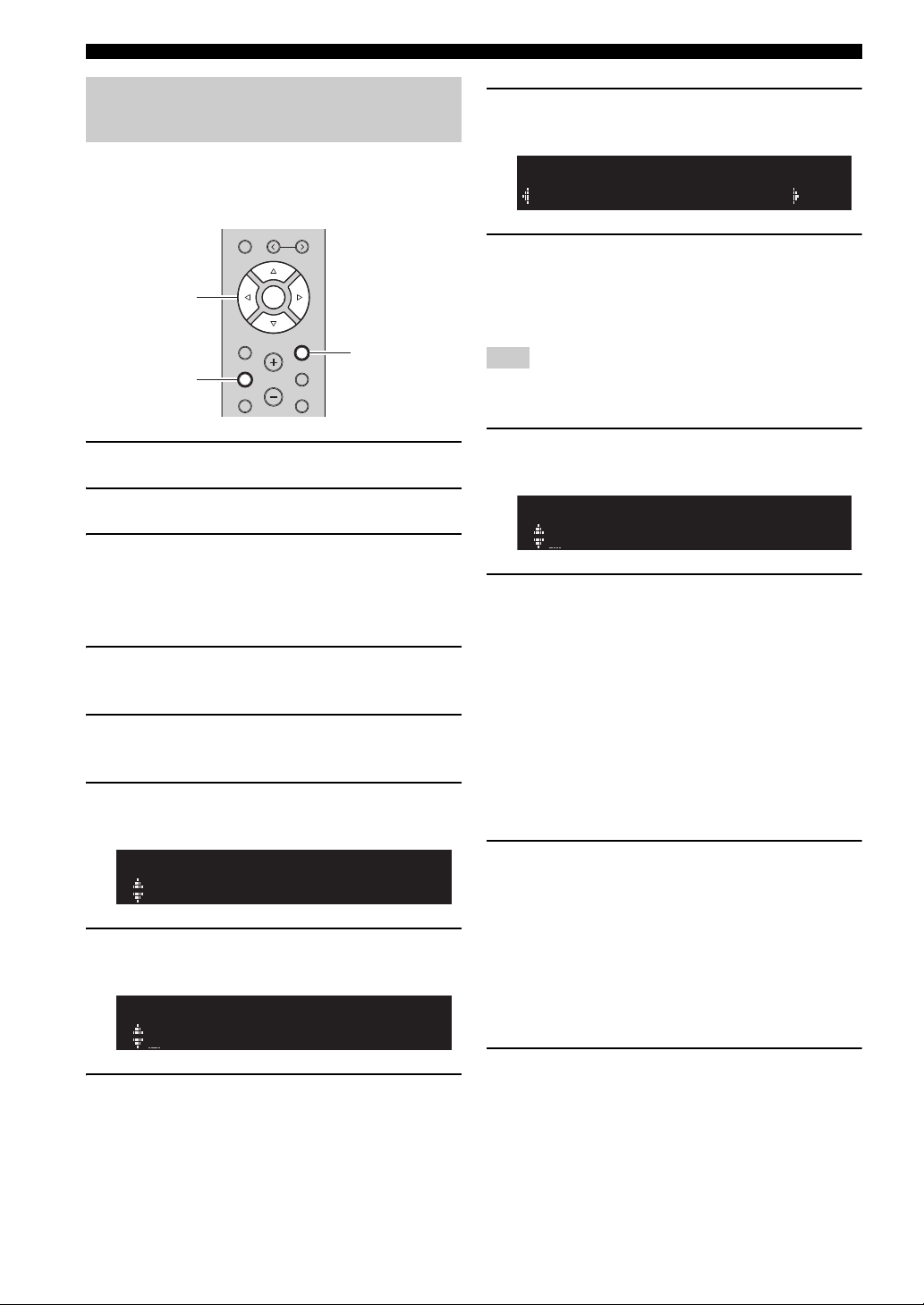
Sharing the iOS device setting
You can easily setup a wireless connection by applying the
connection settings on iOS devices (iPhone/iPod touch).
Before proceeding, confirm that your iOS device is
connected to a wireless router (access point).
If the network connection is not set, when you turn on
this unit, “WAC” (Wireless Accessory Configuration)
appears on the front display, and the iOS device setting
can be shared.
WAC
R-N602 XXXXXX
To share the iOS device setting, perform the network
setting sharing operation on your iOS device.
MEMORY
PRESET
ENTER
HOME
SETUP
VOLUME
RETURN
OPTION
MUTENOW PLAYING
7 Use the cursor keys (B / C) to select the
desired connection method and press
ENTER.
The following connection methods are available.
You can apply the connection settings on the iOS
Wireless
(WAC)
USB
Cable
device to the unit using a wireless connection. For
details, see “Sharing the iOS device setting
wirelessly”. (You need iOS device with iOS 7 or
later.)
You can apply the connection settings on the iOS
device to the unit using a USB cable. For details, see
“Sharing the iOS device setting using a USB cable”.
(You need iOS device with iOS 5 or later.)
Note
When you select “Wireless (WAC)” as the connection method, all
network settings are initialized.
■ Sharing the iOS device setting wirelessly
If you select “Wireless (WAC)” as the connection method,
perform the network setting sharing operation on your iOS
device. (The following procedure is a setup example for
iOS 8.)
1 On the iOS device, select the unit as the
AirPlay speaker in the Wi-Fi screen.
1 Press A to turn on this unit.
2 Press SETUP.
3 Use the cursor keys (B / C) to select
“Network” and press ENTER.
y
To return to the previous state, press RETURN.
4 Use the cursor keys (B / C) to select
“Connection” and press ENTER.
5 Use the cursor keys (B / C) to select
“Wireless” and press ENTER.
WIRELESS
WPS
6 Use the cursor keys (B / C) to select “Share
Setting” and press ENTER.
2 Check the network currently selected and tap
“Next”.
When the sharing process finishes, the unit is
automatically connected to the selected network
(access point).
When the setting finishes, verify whether the unit is
connected to a wireless network (p. 20).
16 En
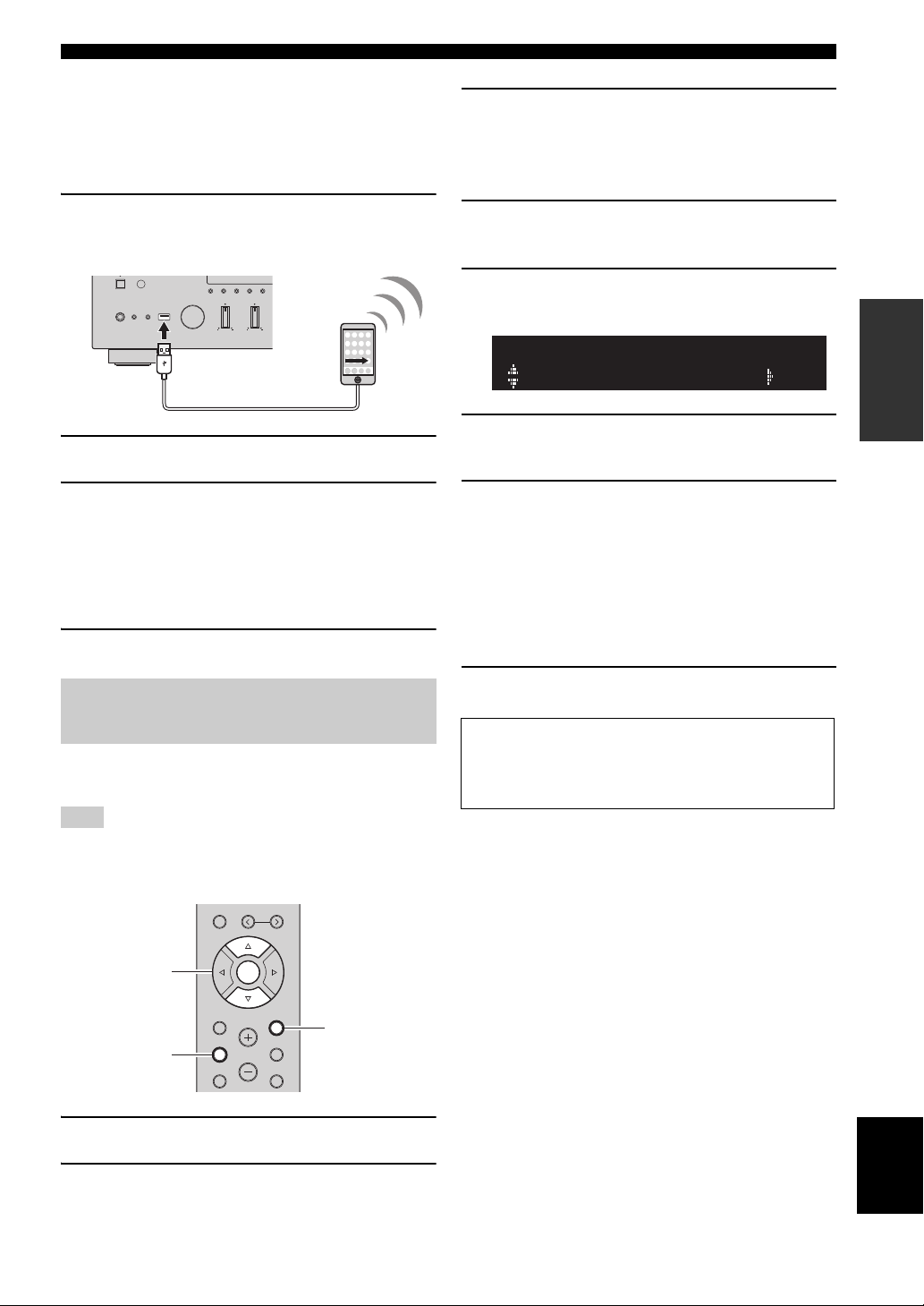
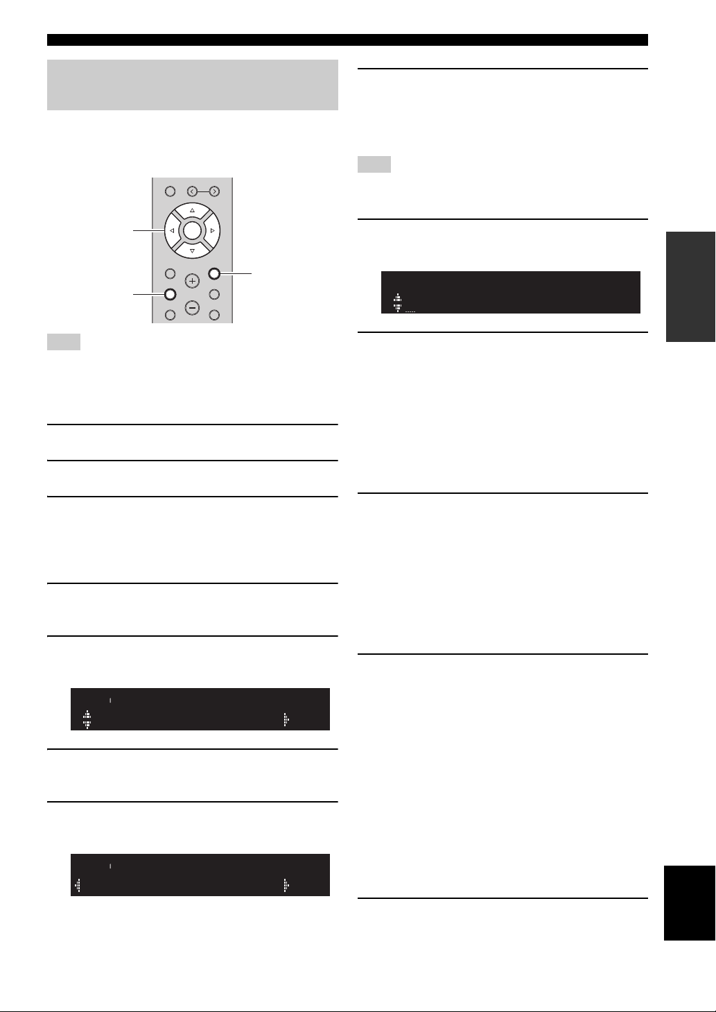
■ Sharing the iOS device setting using a
This unit (front)
RETURN
SETUP
ENTER
Cursor keys B /
C
USB cable
If you select “USB Cable” as the connection method,
follow the procedure below to share the iOS device setting
with the unit.
Connecting to network
3 Use the cursor keys (B / C) to select
“Network” and press ENTER.
y
To return to the previous state, press RETURN.
1 Connect the iOS device to the USB jack, and
disable the screen lock on the iOS device.
MEMORY CLEAR
DIMMER MODE
DISPLAY
BASSINPUT
PHONES
SPEAKERS
AB
5V
1A
TREBLE
2 Press ENTER.
3 Tap “Allow” in the message appeared on the
iOS device.
When the connection process finishes, “Completed”
appears on the front display.
When the setting finishes, verify whether the unit is
connected to a wireless network (p. 20).
4 To exit from the menu, press SETUP.
Using the WPS push button configuration
You can easily set up a wireless connection with one push
of the WPS button.
Note
This configuration does not work if the security method of your
wireless router (access point) is WEP. In this case, use other
connection method.
4 Use the cursor keys (B / C) to select
“Connection” and press ENTER.
5 Use the cursor keys (B / C) to select
“Wireless” and press ENTER.
WIRELESS
WPS
6 Press ENTER twice.
“Connecting” appears on the front display.
7 Push the WPS button on the wireless router
(access point).
When the connection process finishes, “Completed”
appears on the front display. When the setting
finishes, verify whether the unit is connected to a
wireless network (p. 20).
If “Not connected” appears, repeat from Step 1 or try
another connection method.
8 To exit from the menu, press SETUP.
About WPS
WPS (Wi-Fi Protected Setup) is a standard established by the
Wi-Fi Alliance, which allows easy establishment of a
wireless home network.
PREPARATION
1 Press A to turn on this unit.
2 Press SETUP.
MEMORY
PRESET
ENTER
HOME
RETURN
SETUP
VOLUME
OPTION
MUTENOW PLAYING
English
17 En
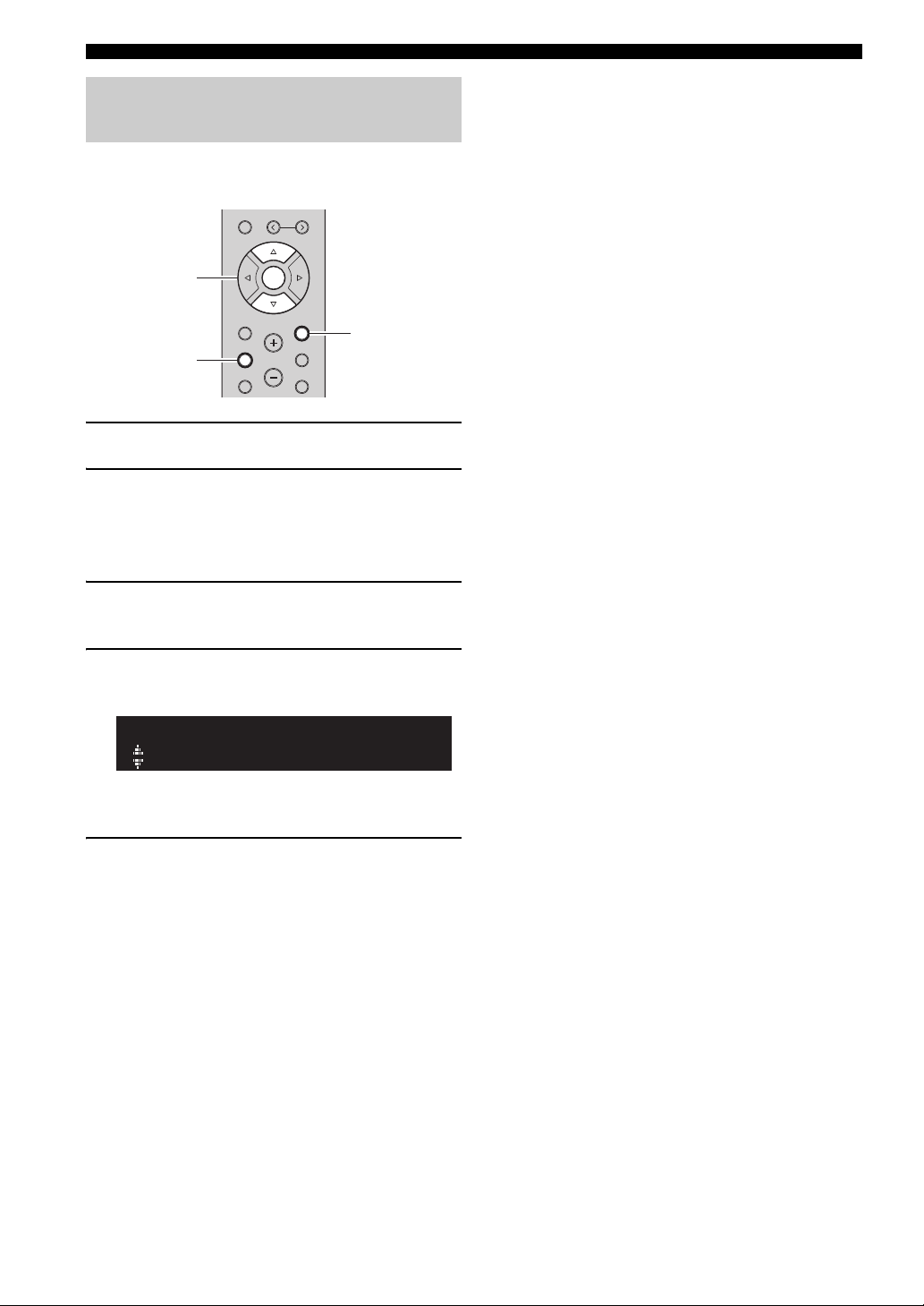
Connecting to network
RETURN
SETUP
ENTER
Cursor keys
B / C / D /
E
KEY
Set the wireless network connection manually
Before performing the following procedure, check the
security method and security key on the wireless router
(access point).
MEMORY
PRESET
ENTER
HOME
SETUP
1 Press A to turn on this unit.
2 Press SETUP.
3 Use the cursor keys (B / C) to select
“Network ” and press ENTER.
y
To return to the previous state, press RETURN.
4 Use the cursor keys (B / C) to select
“Connection” and press ENTER.
5 Use the cursor keys (B / C) to select
“Wireless” and press ENTER.
6 Use the cursor keys (B / C) to select “Manual
Setting” and press ENTER.
VOLUME
RETURN
OPTION
MUTENOW PLAYING
9 Use the cursor keys (B / C) to select
“Security” and press ENTER.
SECURITY
WPA2-PSK(AES)
10 Use the cursor keys (D / E) to select desired
security method and press RETURN.
Settings
None, WEP, WPA2-PSK (AES), Mixed Mode
Note
If you select “None”, the connection may be insecure since the
communication is not encrypted.
11 Use the cursor keys (B / C) to select
“Security Key” and press ENTER.
12 Use the cursor keys to enter the security key
on the wireless router (access point), and
press RETURN to previous state.
If you select “WEP” in step 10, enter either 5 to 13
character string or 10 to 26 hexadecimal digits.
If you select “WPA2-PSK (AES)” or “Mixed Mode”
in step 10, enter either 8 to 63 character string or 64
hexadecimal digits.
Use the cursor keys (D/E) to move the edit position
and the cursor keys (B/C) to select a character.
You can insert / delete a character, by pressing
PRESET i (insert) or PRESET j (delete).
MANUAL
SSID
7 Use the cursor keys (B / C) to select “SSID”
and press ENTER.
SSID
8 Use the cursor keys to enter the SSID on the
wireless router (access point), and press
RETURN to previous state.
Use the cursor keys (D/E) to move the edit position
and the cursor keys (B/C) to select a character.
18 En
13 Use the cursor keys (B / C) to select
“Connect[ENTER]” and press ENTER to save
the setting.
If “ERROR” appears, check the SSID and security
key on the wireless router (access point) and repeat
from Step 7.
If “ERROR” not appears, a connection is success.
Verify whether the unit is connected to a wireless
network (p. 20).
14 To exit from the menu, press SETUP.
Connecting to network
RETURN
SETUP
ENTER
Cursor keys
B / C / D /
E
SSID
W DIRECT
WPA2-PSK(AES)
W DIRECT
Connecting a mobile device to the unit directly (Wireless Direct)
Using Wireless Direct, this unit can operate as a wireless
network access point that mobile devices can directly
connect to.
MEMORY
PRESET
ENTER
HOME
RETURN
SETUP
Note
When the unit is connected to the network with Wireless Direct, it
cannot connect to any other wireless router (access point). To
play back contents from the Internet, connect this unit to a
network with a wired router or wireless router (access point).
1 Press A to turn on this unit.
2 Press SETUP.
VOLUME
OPTION
MUTENOW PLAYING
8 Use the cursor keys (D / E) to select desired
security method and press RETURN.
Settings
None, WPA2-PSK (AES)
Note
If you select “None”, the connection may be insecure since the
communication is not encrypted.
9 Use the cursor keys (B / C) to select
“Security Key” and press ENTER.
KEY
10 Use the cursor keys to enter the security key
on this unit, and press RETURN to previous
state.
Enter either 8 to 63 character string or 64
hexadecimal digits.
Use the cursor keys (D / E) to move the edit position
and the cursor keys (B / C) to select a character.
You can insert / delete a character, by pressing
PRESET i (insert) or PRESET j (delete).
PREPARATION
3 Use the cursor keys (B / C) to select
“Network” and press ENTER.
y
To return to the previous state, press RETURN.
4 Use the cursor keys (B / C) to select
“Connection” and press ENTER.
5 Use the cursor keys (B / C) to select
“WirelesDirect” and press ENTER.
6 Press ENTER to check the SSID on this unit,
and press RETURN to previous state.
7 Use the cursor keys (B / C) to select
“Security” and press ENTER.
11 Use the cursor keys (B / C) to select
“Connect[Enter]” and press ENTER to save
the setting.
The SSID and security key information is required
for setup of a mobile device.
When you select the “SSID” in step 6, you can check
the configured SSID on this unit. The SSID of this
unit can be change by using cursor keys (B / C / D /
E).
12 Configure the Wi-Fi settings of a mobile
device.
For details on settings of your mobile device, refer to
the instruction manual of the mobile device.
(1) Enable the Wi-Fi function on the mobile device.
(2) Select the SSID of this unit from the list of
available access points.
(3) When you are prompted for a password, enter the
security key displayed in Step 10.
If “ERROR” appears, check the security key on this
unit and repeat Step 12.
If “ERROR” not appears, a connection is success.
Verify whether the unit is connected to a wireless
network (p. 20).
English
13 To exit from the menu, press SETUP.
19 En
Connecting to network
RETURN
SETUP
ENTER
Cursor keys B /
C
Verify the network connection status
Perform the following procedure to verify the unit’s
connection to a network.
MEMORY
PRESET
ENTER
HOME
SETUP
VOLUME
RETURN
OPTION
MUTENOW PLAYING
1 Press SETUP.
2 Use the cursor keys (B / C) to select
“Network” and press ENTER.
y
To return to the previous state, press RETURN.
3 Use the cursor keys (B / C) to select
“Information” and press ENTER.
4 Use the cursor keys (B / C) to select
“STATUS”.
STATUS
Connect
When “Connect” appears, the unit is connected to a
network. If “Disconnect” appears, reset connection.
5 To exit from the menu, press SETUP.
20 En
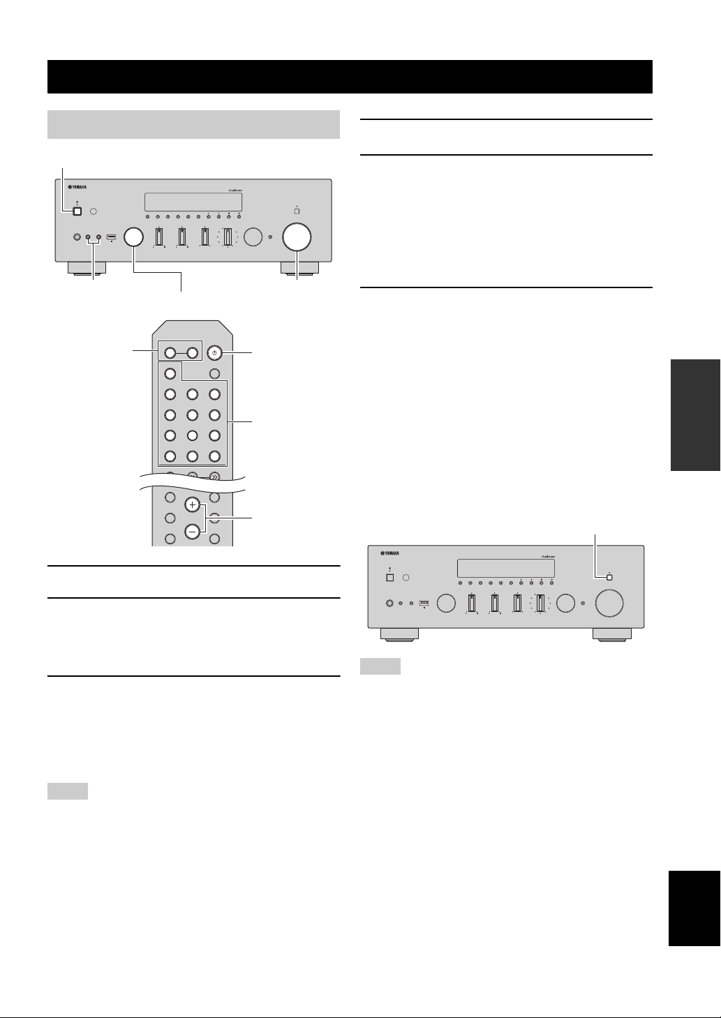
BASIC OPERATION
A (power)
SPEAKERS A/B
INPUT selector
VOLUME control
SETUP
HOME
MUTENOW PLAYING
VOLUME
RETURN
OPTION
Input selection
keys
A (power)
VOLUME
SPEAKERS A/B
PURE DIRECT switch
Playback
Playing a source
MEMORY CLEAR
DIMMER MODE
DISPLAY
PHONES
SPEAKERS
AB
5V
1A
BASSINPUT
SPEAKERS
A
PHONO
COAX 1 COAX 2
OPT 1 OPT 2 CD
LINE 1
TUNER
BAND
TREBLE
B
LINE 2 LINE 3
NET USB
BAND
BALANCE
LR
TUNING
SLEEP
BLUETOOTH
4 Play the source.
5 Rotate the VOLUME control on the front
panel (or press VOLUME +/– on the remote
TUNINGPRESET
LOUDNESS
SELECT
FLAT
-30dB
PURE DIRECT
PUSH - ENTER
VOLUME
RETURN
CONNECT
control) to adjust the sound output level.
y
You can adjust the tonal quality by using the BASS, TREBLE,
BALANCE and LOUDNESS controls or the PURE DIRECT
switch on the front panel.
6 When you finish using, press A (Power) on
the front panel to turn off the power.
When you press A (Power) on the remote control,
this unit set to standby mode.
■ Enjoying pure high fidelity sound
(Pure Direct)
When the PURE DIRECT switch is turned on, routes
input signals from your audio sources so that the input
signals bypass the BASS, TREBLE, BALANCE and
LOUDNESS controls, thus eliminating any alterations to
the audio signals and creating the purest possible sound.
The PURE DIRECT indicator lights up and the front
display turns off after a few seconds.
OPERATION
BASIC
1 Press A (power) to turn on this unit.
2 Rotate the INPUT selector on the front panel
3 Press SPEAKERS A and/or SPEAKERS B on
Notes
• When one set of speakers is connected using bi-wire connections,
or when using two sets of speakers simultaneously (A and B),
make sure “A” and “B” are displayed on the front display.
• When listening with headphones, turn off the speakers.
(or press one of the input selection keys on
the remote control) to select the input source
you want to listen to.
the front panel or on the remote control to
select speakers A and/or speakers B.
When speaker set A or speaker set B are turned on,
“A” or “B” is displayed on the front display
accordingly (p. 7).
PHONES
SPEAKERS
AB
5V
1A
BASSINPUT
BALANCE
LR
LOUDNESS
SELECT
PUSH - ENTER
FLAT
-30dB
TREBLE
TUNINGPRESET
BAND
MEMORY CLEAR
DIMMER MODE
DISPLAY
PURE DIRECT
VOLUME
RETURN
CONNECT
Notes
• When the PURE DIRECT switch is turned on, the front display
turns off.
• The BASS, TREBLE, BALANCE, and LOUDNESS controls do
not function while the PURE DIRECT switch is turned on.
21 En
English
Playback
VOLUME
PURE DIRECT
RETURN
CONNECT
PUSH - ENTER
TUNINGPRESET
BAND
MEMORY CLEAR
BASSINPUT
5V
1A
BALANCE
LR
TREBLE
LOUDNESS
FLAT
-30dB
DIMMER MODE
DISPLAY
SELECT
PHONES
SPEAKERS
AB
BASS TREBLE
VOLUME
PURE DIRECT
RETURN
CONNECT
PUSH - ENTER
TUNINGPRESET
BAND
MEMORY CLEAR
BASSINPUT
5V
1A
BALANCE
LR
TREBLE
LOUDNESS
FLAT
-30dB
DIMMER MODE
DISPLAY
SELECT
PHONES
SPEAKERS
AB
BALANCE
VOLUME
PURE DIRECT
RETURN
CONNECT
PUSH - ENTER
TUNINGPRESET
BAND
MEMORY CLEAR
BASSINPUT
5V
1A
BALANCE
LR
TREBLE
LOUDNESS
FLAT
-30dB
DIMMER MODE
DISPLAY
SELECT
PHONES
SPEAKERS
AB
VOLUMELOUDNESS
SETUP
HOME
MUTENOW PLAYING
VOLUME
RETURN
OPTION
VOLUME +/–
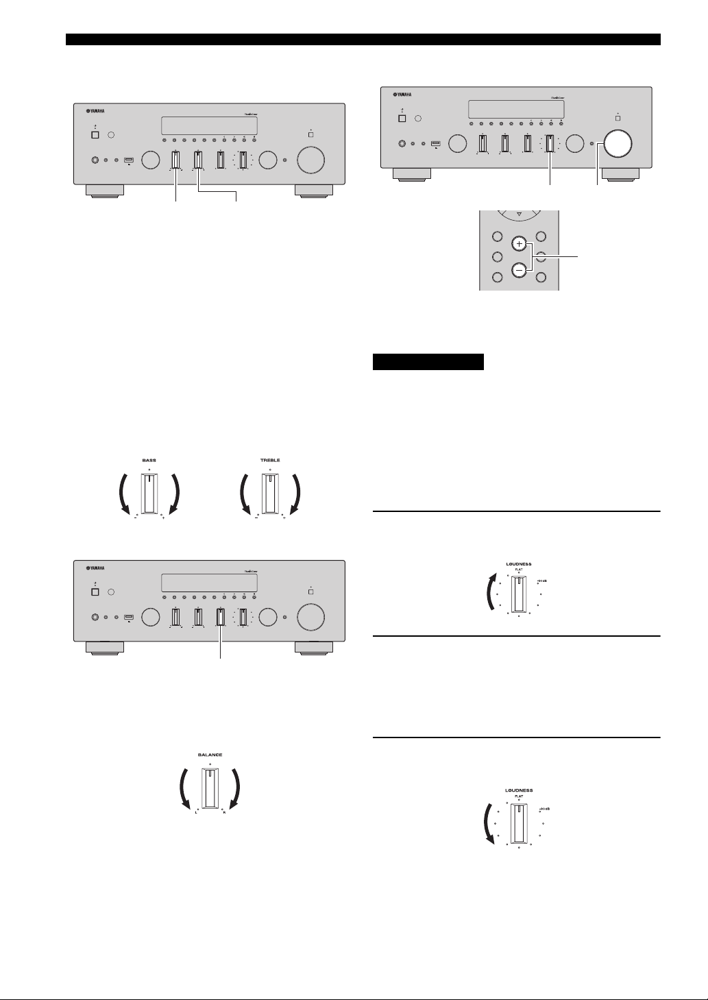
■ Adjusting the BASS and TREBLE
controls
The BASS and TREBLE controls adjust high and low
frequency response.
The center position produces a flat response.
BASS control
When you feel there is not enough bass (low frequency
sound), rotate clockwise to boost. When you feel there is
too much bass, rotate counterclockwise to suppress.
Control range: –10 dB to +10 dB (20 Hz)
TREBLE control
When you feel there is not enough treble (high frequency
sound), rotate clockwise to boost. When you feel there is
too much treble, rotate counterclockwise to suppress.
Control range: –10 dB to +10 dB (20 kHz)
■ Adjusting the LOUDNESS control
Retain a full tonal range at any volume level, thus
compensating for the human ears’ loss of sensitivity to
high and low-frequency ranges at low volume.
CAUTION
If the PURE DIRECT switch is turned on with the
LOUDNESS control set at a certain level, the input signals
bypass the LOUDNESS control, resulting in a sudden
increase in the sound output level. To prevent your ears or
the speakers from being damaged, be sure to press the
PURE DIRECT switch after lowering the sound output
level or after checking that the LOUDNESS control is
properly set.
1 Set the LOUDNESS control to the FLAT
■ Adjusting the BALANCE control
position.
2 Rotate the VOLUME control on the front
panel (or press VOLUME +/– on the remote
The BALANCE control adjusts the sound output balance
of the left and right speakers to compensate for sound
imbalance caused by speaker locations or listening room
control) to set the sound output level to the
loudest listening level that you would listen
to.
conditions.
3 Rotate the LOUDNESS control until the
desired volume is obtained.
y
After setting the LOUDNESS control, enjoy listening to music at
your preferred volume level. If the effect of the LOUDNESS
control setting is too strong or weak, readjust the LOUDNESS
22 En
control.
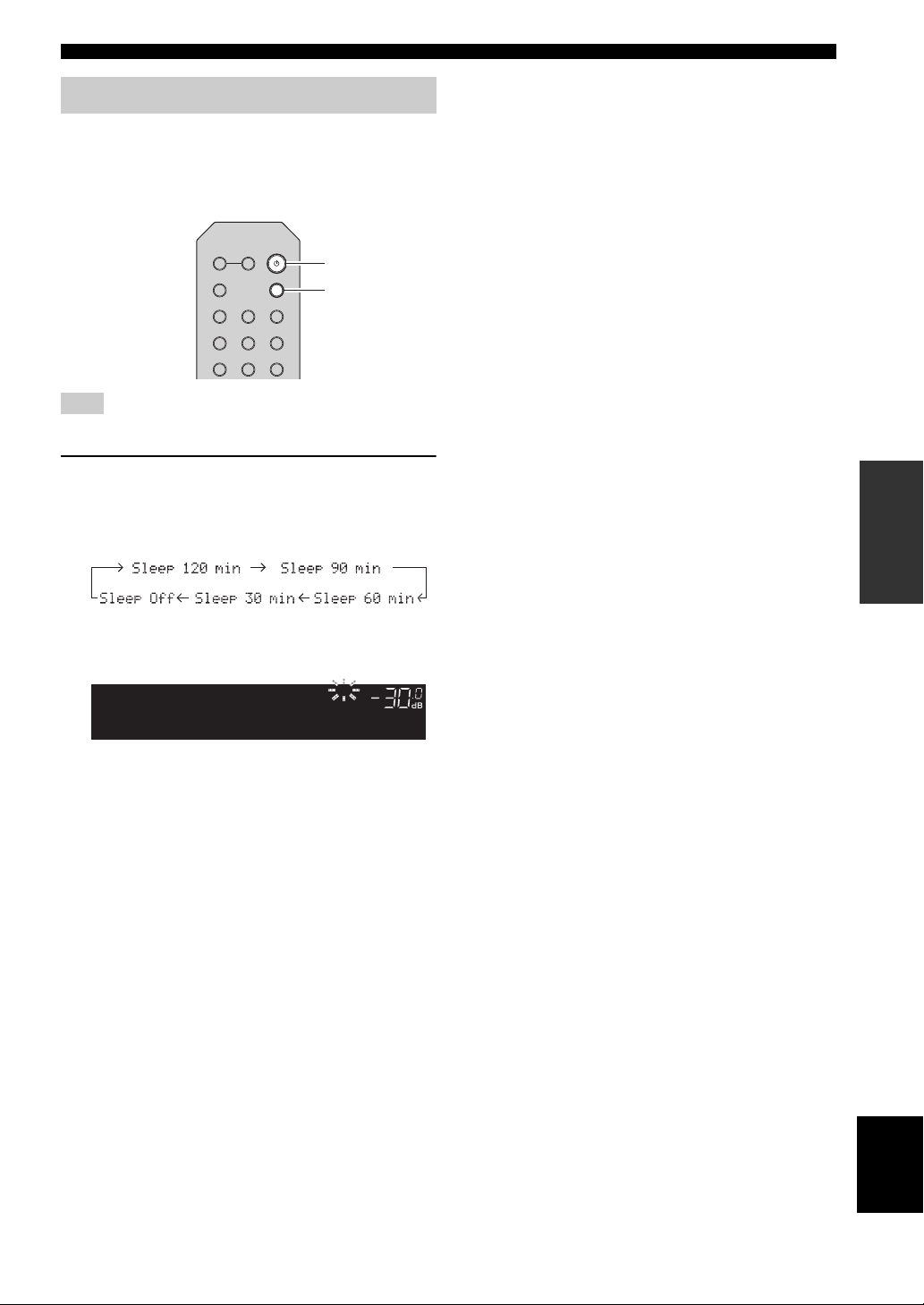
Using the sleep timer
A
SLEEP
(power)
VOL.
A
Sleep 120min.
SLEEP
Use this feature to automatically set this unit to standby
mode after a certain amount of time. The sleep timer is
useful when you are going to sleep while this unit is
playing or recording a source.
SPEAKERS
B
A
PHONO
COAX 1 COAX 2
OPT 1 OPT 2 CD
LINE 1
Note
The sleep timer can only be set with the remote control.
SLEEP
BLUETOOTH
LINE 2 LINE 3
Playback
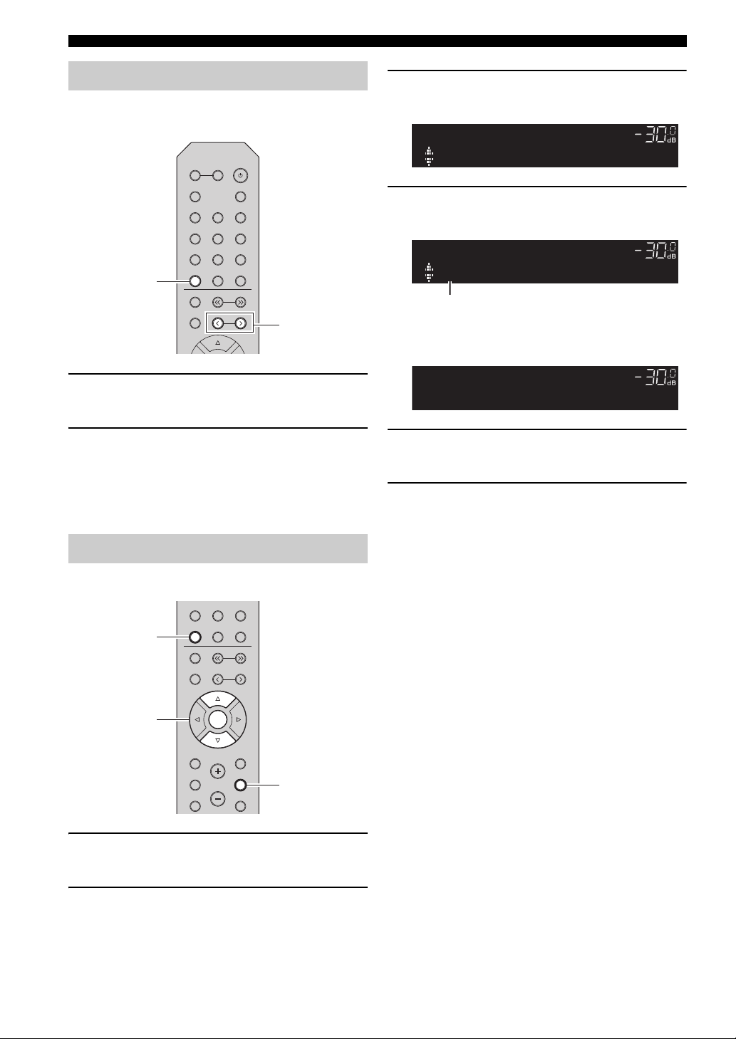
1 Press SLEEP repeatedly to set the amount of
time before this unit is set to standby mode.
Each time you press SLEEP, the front display
changes as shown below.
The SLEEP indicator blinks while setting the amount
of time for the sleep timer.
If the sleep timer is set, the SLEEP indicator on the
front display lights up.
y
• To disable the sleep timer, select “Sleep Off”.
• The sleep timer setting can also be canceled by pressing
A (power) to set this unit to standby mode.
OPERATION
BASIC
English
23 En
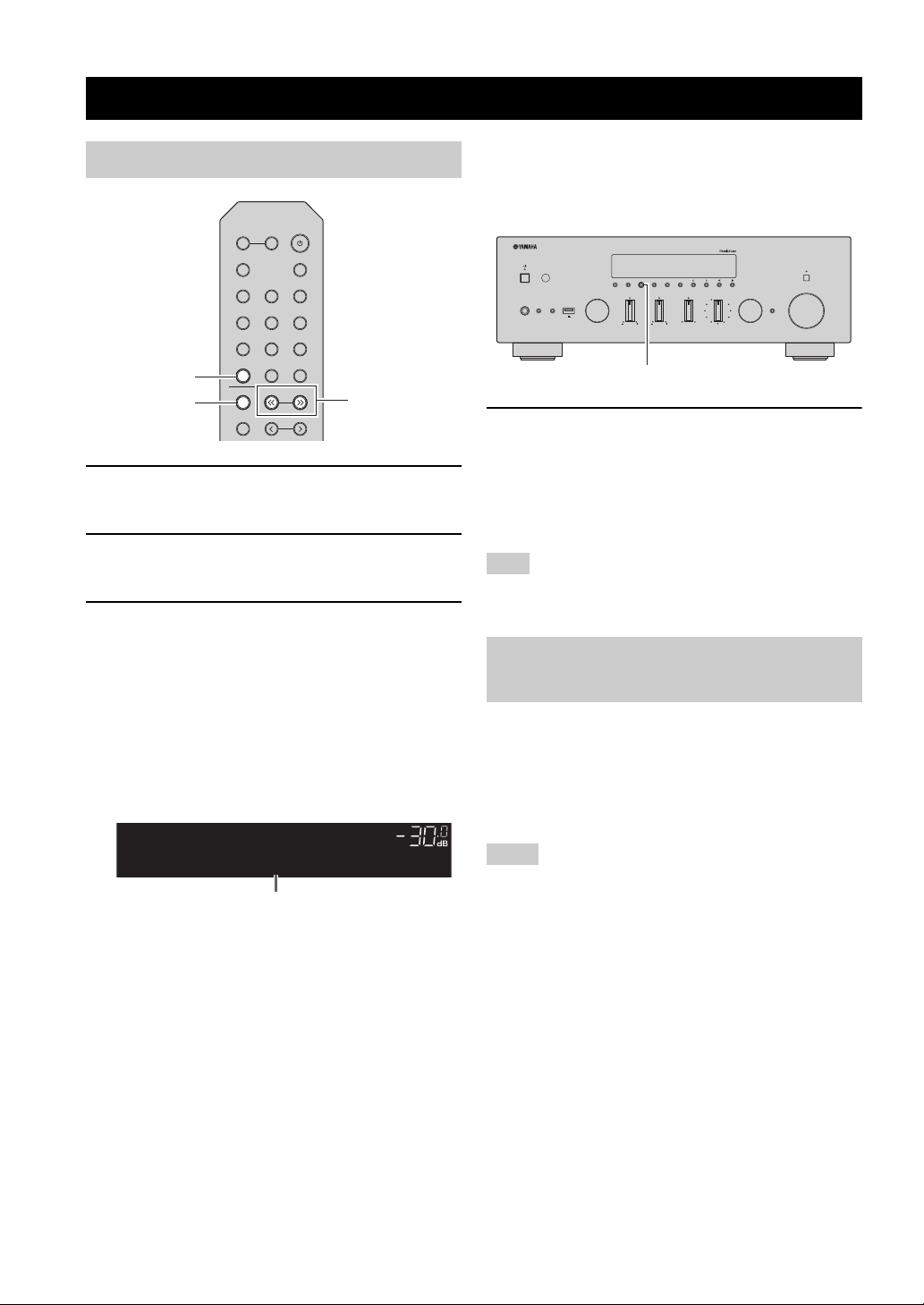
Listening to FM/AM radio
TUNING jj / ii
TUNER
BAND
VOL.
TUNEDSTEREO
A
FM 98.50MHz
Frequency
VOLUME
PURE DIRECT
RETURN
CONNECT
PUSH - ENTER
TUNINGPRESET
BAND
MEMORY CLEAR
BASSINPUT
5V
1A
BALANCE
LR
TREBLE
LOUDNESS
FLAT
-30dB
DIMMER MODE
DISPLAY
SELECT
PHONES
SPEAKERS
AB
MODE
FM/AM tuning
SPEAKERS
B
A
PHONO
COAX 1 COAX 2
OPT 1 OPT 2 CD
LINE 1
TUNER
BAND
MEMORY
1 Press TUNER to select “TUNER” as the input
source.
2 Press BAND repeatedly to select the
reception band (FM or AM).
3 Press and hold TUNING jj / ii for more than
1 second to begin tuning.
Press ii to tune in to a higher frequency.
Press jj to tune in to a lower frequency.
The frequency of the received station is shown in the
front display.
If a broadcast is being received, “TUNED” indicator
on the front display will be lit. If a stereo broadcast is
being received, the “STEREO” indicator will also lit.
SLEEP
BLUETOOTH
LINE 2 LINE 3
NET USB
TUNING
PRESET
■ Improving FM reception (FM mode)
If the signal from the station is weak and the sound quality
is not good, set the FM band reception mode to monaural
mode to improve reception.
1 Press MODE repeatedly to select “Stereo”
(automatic stereo mode) or “Mono”
(monaural mode) when this unit is tuned in to
an FM radio station.
When Mono is selected, FM broadcasts will be heard
in monaural sound.
Note
The STEREO indicator on the front panel lights up while
listening to a station in stereo mode.
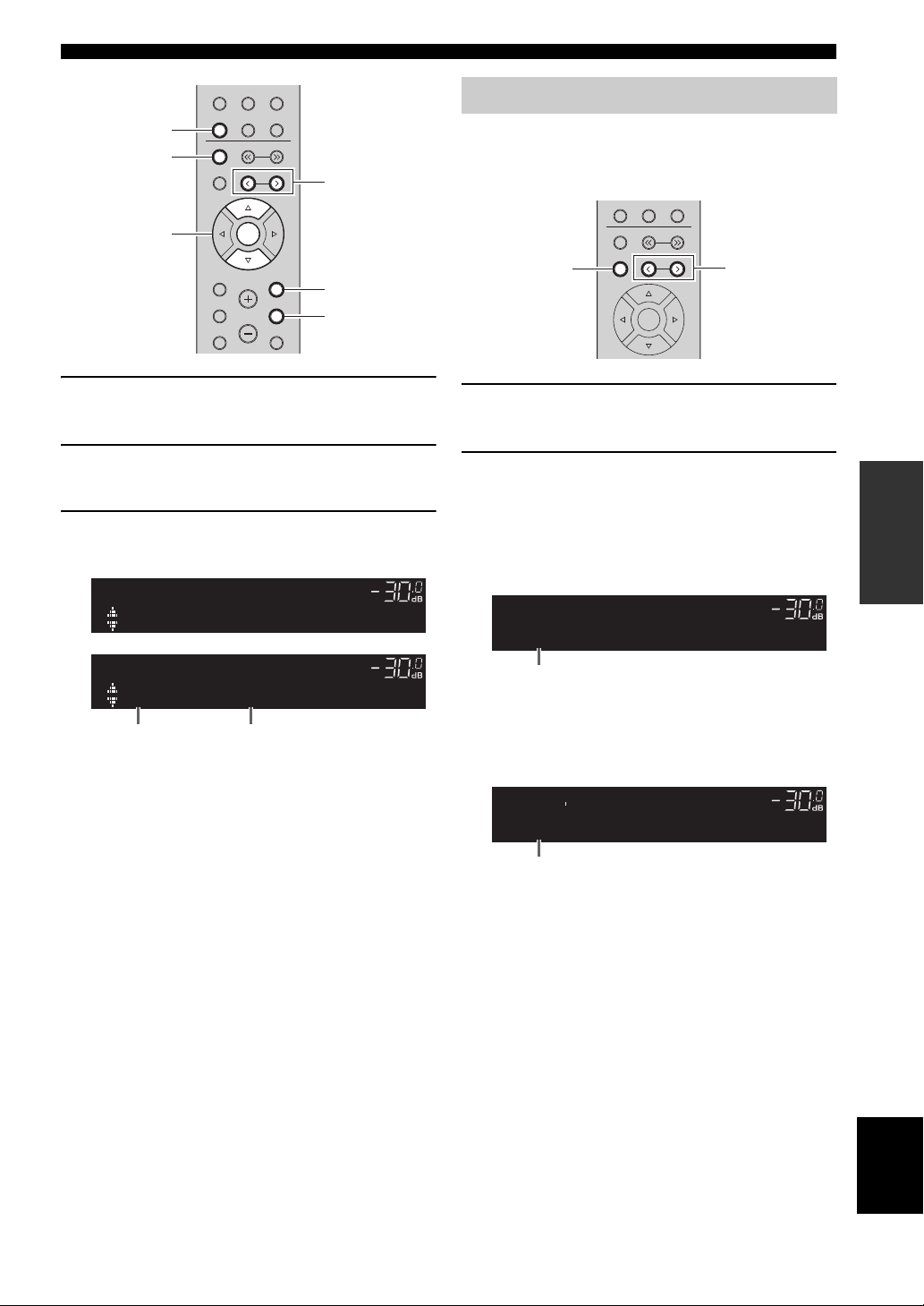
Automatic preset tuning (FM stations only)
You can use the automatic preset tuning function to
automatically register FM stations as presets. This
function enables this unit to automatically tune in to FM
stations that have a strong signal and register up to 40 of
those stations in order. You can then easily recall any
preset station by selecting its preset number.
y
• If the station signals are weak, tuning search does not stop at the
desired station.
• When the signal reception for an FM radio station is unstable,
switching to monaural may improve it.
24 En
Notes
• If a station is registered to a preset number that already has a
station registered to it, the previously registered station is
overwritten.
• If the station you want to register is weak in signal strength, try
using the manual preset tuning method.
y
• FM stations registered as presets using the automatic preset
registration feature will be heard in stereo.
• Only Radio Data System broadcasting stations are registered
automatically by the Auto Preset function.
LINE 1
PRESET j / i
RETURN
OPTION
TUNER
BAND
ENTER
Cursor keys B /
C
VOL.
A
Auto Preset
OPTION
VOL.
A
01:FM 87.50MHz
READY
Preset number Frequency
Preset number
“Empty” (not in use) or the frequency currently registered
TUNER
BAND
MEMORY
HOME
SETUP
LINE 2 LINE 3
NET USB
TUNING
PRESET
ENTER
VOLUME
RETURN
OPTION
MUTENOW PLAYING
Listening to FM/AM radio
Manual tuning preset
Select a radio station manually and register it to a preset
number. You can then easily recall any preset station by
selecting its preset number.
TUNER
NET USB
BAND
TUNING
MEMORY
MEMORY
PRESET
ENTER
PRESET j / i
1 Press TUNER to select “TUNER” as the input
source.
2 Press OPTION on the remote control.
The “Option” menu is displayed (p. 43).
3 Press B / C to select “Auto Preset”, and then
press ENTER.
This unit starts scanning the FM band about 5
seconds later from the lowest frequency upwards.
To begin scanning immediately, hold down ENTER.
y
• Before scanning begins, you can specify the first preset number
to be used by pressing PRESET j / i or cursor key (B/C) on the
remote control.
• To cancel scanning, press BAND or RETURN.
1 Follow “FM/AM tuning” (p.24) to tune into the
desired radio station.
2
Hold down MEMORY for more than 2 seconds.
The first time that you do register a station, the selected
radio station will be registered to the preset number
“01”. Thereafter, each radio station you select will be
registered to the next empty (unused) preset number
after the most recently registered number.
TUNEDSTEREO
MEMORY
A
VOL.
01:FM 98.50MHz
y
To select a preset number for registering, press MEMORY once
after tuning into the desired radio station, press PRESET j / i to
select a preset number, and then press MEMORY again.
TUNEDSTEREO
9850
A
VOL.
02:Empty
OPERATION
BASIC
When scanning is complete, “FINISH” is displayed and
then the display returns to original state.
English
25 En
Listening to FM/AM radio
TUNER
PRESET j / i
OPTION
ENTER
TUNER
Cursor keys B /
C
Preset station to be cleared
VOL.
01:Cleard
CLEAR
A
Recalling a preset station
You can recall preset stations that were registered using
automatic station preset or manual station preset.
SPEAKERS
B
A
PHONO
COAX 1 COAX 2
OPT 1 OPT 2 CD
LINE 1
TUNER
BAND
MEMORY
SLEEP
BLUETOOTH
LINE 2 LINE 3
NET USB
TUNING
PRESET
1 Press TUNER to select “TUNER” as the input
source.
2 Press PRESET j / i to select a preset
number.
y
• Preset numbers to which no stations are registered are skipped.
• “No Presets” is displayed if no stations are registered.
Clearing a preset station
Clear radio stations registered to the preset numbers.
LINE 1
LINE 2 LINE 3
TUNER
NET USB
BAND
TUNING
MEMORY
PRESET
3 Use the cursor keys to select “Clear Preset”
and press ENTER.
OPTION
VOL.
Clear Preset
4 Use the cursor keys (B / C) to select a preset
station to be cleared and press ENTER.
TUNEDSTEREO
CLEAR
A
VOL.
01:FM 98.50MHz
If the preset station is cleared, “Cleared” appears and
then the next in-use preset number is displayed.
5 Repeat step 4 until all desired preset stations
are cleared.
6 To exit from the “Option” menu, press
OPTION.
y
You can clear a preset station from the front panel.
(1) Press CLEAR on the front panel.
(2) Press PRESET D/E to select the preset station that you want
to clear.
(3) Press SELECT/ENTER or CLEAR to clear the preset station.
1 Press TUNER to select “TUNER” as the input
source.
2 Press OPTION.
26 En
ENTER
HOME
SETUP
VOLUME
RETURN
OPTION
MUTENOW PLAYING
 Loading...