

Page 1

Page 2

Page 3

Page 4

Owner’s Manual
Reference
Introduction
Thank you for purchasing the Yamaha QY700 music sequencer.
The QY700 is a 20 song / 32 track sequencer with 1/480th quarter note resolution featuring a built-in XG- and GM-compatible highquality AWM2 tone generator, all contained in a newly-designed package. The Style Sequencer functions that were so popular on the
QY300 etc. have been enhanced and made easier to use. A large LCD display also makes operation easier and more intuitive.
In order to take full advantage of the QY700’s functionality , please make good use of this o wner’ s manual. Once y ou hav e read it, keep it
in a safe and convenient place for reference should any questions arise later.
3
Page 5

Features of the QY700
Features of the QY700
Powerful sequencer functionality
The sequencer of the QY700 provides 32 sequence tracks and 16 pattern tracks, and up to 110,000 notes of storage
capacity for professional-level sequencing power. Note timing resolution is 1/480th of a quarter note. Memory is
backed up, so your data will not disappear when the power is turned off. Play Effect functions and a full complement
of editing jobs allow you to edit and modify your data as desired. Play Effects provide a Groo ve Quantize function that
lets you instantly produce a variety of different groove feelings. Also provided are jobs such as Chord Sort and Chord
Separate, convenient for entering guitar strokes.
Functional music production environment with Songs, Patterns, and Phrases
The QY700’s Auto-Accompaniment functionality provides a highly practical music production environment that lets
you use patterns and phrases to create your song.
Easy operation with large display, dials, function buttons, and direct buttons
The large 320 × 240 dot full-graphic display provides you with plenty of information for efficient music-making. For
example, playback data can be viewed not only as an event list, but also graphically in a track-view or piano-roll
display.
The jog dial provides an easy way to modify data, and the shuttle dial lets you rewind/fast-forward intuiti v ely through
data just as on a VTR.
Full assortment of preset phrases
The QY700 provides a vast 3,876 types of preset phrases from all musical genres. All preset phrases have been carefully selected for immediate musical usefulness. Simply by combining preset phrases into patterns, you can create
backing data with infinite variety.
Undo/redo function
The QY700 provides an Undo/Redo job. Even if recor ding, editing, or job execution has caused your important data to
disappear, you will always be able to recover it.
4
Page 6

XG tone generator for rich expressiveness
The QY700 features an XG-compatible tone generator with 491 high-quality voices and 3 high-quality effect systems,
providing the rich expressiveness that you expect from XG.
Wide range of compatibility
The QY700’s tone generator section is compatible with XG and with the GM system le vel 1 tone generator format. The
sequencer section is compatible with ESEQ and SMF (Standard MIDI File) formats 0/1. Playback data that was
created on the QS300 music synthesizer can also be played back on the QY700. You can also playback commercially
available “XG-compatible song data” for additional enjoyment.
Features of the QY700
GM System Level 1
“GM System Level 1” is a standard specification that defines the arrangement of voices in a tone generator and its
MIDI functionality, ensuring that data can be played back with substantially the same sounds on any GM-compatible
tone generator, regardless of its manufacturer or model.
Tone generators and song data that meet the “GM System Level 1” bear this GM logo.
XG
“XG” is a tone generator format that expands the voice arrangement of the “GM System Level 1” specif ication to meet
the ever-increasing demands of today’s computer peripheral environment, providing richer expressive power while
maintaining upward compatibility of data. “XG” greatly expands “GM System Level 1” by def ining the ways in which
voices are expanded or edited and the structure and type of effects.
When commercially available song data bearing the XG logo is played back on a tone generator which bears the XG
logo, you will enjoy a full musical experience that includes unlimited expansion voices and effect functions.
5
Page 7

How to use the manuals
How to use the manuals
The documentation for the QY700 consists of the following two manuals. Understand the role of each manual, and refer to them as necessary.
Owner’s Manual: Reference (this manual)
This explains precautions for use, how to make connections, and all parameters and commands. Use this manual like a dictionary whenever
you need to.
Chapter 1. BASIC CONCEPTS
Chapter 2. SONG MODE
Chapter 3. VOICE MODE
Chapter 4. EFFECT MODE
Chapter 5. PATTERN MODE
Chapter 6. UTILITY MODE
Chapter 7. DISK MODE
“Song mode” and “Pattern mode” have several functions in common.
In this manual, explanations for these common functions is given in greatest detail in chapter 2 “SONG MODE”. Some of the overlapping
explanation in chapter 5 “PATTERN MODE” is omitted. In such cases, the appropriate page of chapter 2 “SONG MODE” is indicated so that
you can refer to it.
Owner’s Manual: QY700 Reference Listings
This is a booklet that contains various lists such as the Voice list, Preset Phrase list, Effect list, Chord Type list, MIDI data format, and MIDI
implementation chart.
Printing conventions in this manual
This manual uses the following icons to indicate buttons and to distinguish different types of information.
s This indicates a panel button. The characters in the box indicate the characters printed on the panel. Buttons for which there are no
characters printed on the panel are indicated by the symbol printed on the panel, such as l. In the case of the function buttons 1
– 6, the function corresponding to each button is also given; for example, 3 (Effect).
[Explanation]
This icon indicates an explanation of the function.
0101
1101
[Setting values]
This icon indicates the range of values that can be set for that function.
6
Page 8
Printing conventions in this manual
[Procedure]
This icon indicates the actual procedure for using the function.
[Supplementary comments]
This icon indicates supplementary explanations related to the function, examples of use, and hints.
[Caution]
This icon indicates a caution. To avoid erasing or damaging important data, be sure to read such sections.
+ This icon means that an operation needs to be performed while doing something else. For example, s + y means “hold down
s and press y”.
/ This icon means “or”. For example,n/ymeans that you should press either thenor theykey.
→ This icon indicates the sequence in which buttons must be pressed. For example, numeric keys → e means that you must use the
numeric keys to select a value and then press the e button.
▼ This icon indicates the result of an operation.
→ p.● ● This indicates the page on which a related function or item is explained. Refer to these pages as necessary.
7
Page 9

Finding the information that you need
Finding the information that you need
In order to find the information that you need, you can make use of the following pages.
Table of contents (→ p.9)
Locate the desired information within the flow of the entire manual.
Front and rear panels (→ p.12)
Here you can read about the name and location of each button and control, and read about their function.
Function tree (→ p.34)
This lets you locate the desired information within the structure of the command hierarchy.
Glossary (→ p.324)
This section contains unfamiliar terms or phrases in alphabetical order with their explanations.
Index (→ p.328)
This lets you search alphabetically for unfamiliar terms to find pages on which they are discussed and pages on which related topics appear.
8
Page 10

Table of contents
Introduction
Features of the QY700........................................................................................................................................................................................4
How to use the manuals......................................................................................................................................................................................6
Printing conventions in this manual ...................................................................................................................................................................6
Finding the information that you need ...............................................................................................................................................................8
SETUP
1. Front and rear panels ................................................................................................................................................................................... 12
2. Connections.................................................................................................................................................................................................18
3. Using the Style and Demonstration disk ..................................................................................................................................................... 22
Table of contents
Top panel................................................................................................................................................................................12
Rear panel ..............................................................................................................................................................................16
Floppy disk drive ...................................................................................................................................................................17
Power supply connections......................................................................................................................................................18
Audio equipment connections ............................................................................................................................................... 19
Connecting a foot switch .......................................................................................................................................................20
Connecting external MIDI devices ........................................................................................................................................20
Connecting an MTR (multi-track recorder)...........................................................................................................................21
Connecting two or more devices............................................................................................................................................21
Contents of the disk ...............................................................................................................................................................22
Listening to the demo playback .............................................................................................................................................22
Restoring the factory settings ................................................................................................................................................ 23
Chapter 1. BASIC CONCEPTS
1. Mode structure ............................................................................................................................................................................................ 26
2. Function tree................................................................................................................................................................................................34
3. How the QY700 is organized ...................................................................................................................................................................... 36
4. Sequencer block ..........................................................................................................................................................................................37
5. The tone generator block.............................................................................................................................................................................43
6. Controller block .......................................................................................................................................................................................... 46
7. Effect block .................................................................................................................................................................................................47
8. Basic operation............................................................................................................................................................................................51
9. Song creation procedure..............................................................................................................................................................................56
Create pattrens .......................................................................................................................................................................57
Editing a pattern.....................................................................................................................................................................59
Pattern track recording........................................................................................................................................................... 60
Chord track recording ............................................................................................................................................................61
Voice settings .........................................................................................................................................................................62
Realtime record of track 2 ..................................................................................................................................................... 62
Step recording of track 1........................................................................................................................................................63
Editing tracks 1 and 2 ............................................................................................................................................................65
Modifying the voice of track 1 .............................................................................................................................................. 66
Save to floppy disk.................................................................................................................................................................67
Chapter 2. SONG MODE
SONG MODE Overview..................................................................................................................................................................................70
1. SONG PLAY ............................................................................................................................................................................................... 72
2. Play Effects..................................................................................................................................................................................................80
Groove Quantizing.................................................................................................................................................................82
Clock Shift, Gate Time, and Velocity ....................................................................................................................................90
Transposition..........................................................................................................................................................................94
Drum T able Edit.....................................................................................................................................................................97
3. Track V iew ................................................................................................................................................................................................100
4. Output Channels........................................................................................................................................................................................103
9
Page 11

Table of contents
5. Song Recording ......................................................................................................................................................................................... 106
Recording Standby...............................................................................................................................................................108
Realtime Recording: Sequence Tracks (TR1,...,TR32) .......................................................................................................112
Realtime Recording: PATTERN Track................................................................................................................................113
Realtime Recording: CHORD Track ................................................................................................................................... 115
Realtime Recording: TEMPO Track....................................................................................................................................117
Punch Recording..................................................................................................................................................................118
Step Recording: Sequence Tracks (TR1,...,TR32)...............................................................................................................120
Step Recording: PATTERN track ........................................................................................................................................125
Step Recording: CHORD track............................................................................................................................................127
6. Song Editing..............................................................................................................................................................................................129
1 (Graphic) Graphic screen .......................................................................................................................................135
7. Song Jobs .................................................................................................................................................................................................. 138
Chapter 3. VOICE MODE
About voice mode...........................................................................................................................................................................................168
1. Mixer .........................................................................................................................................................................................................170
2. Tune...........................................................................................................................................................................................................174
3. Voice edit...................................................................................................................................................................................................176
4. Drum Setup Edit........................................................................................................................................................................................182
Chapter 4. EFFECT MODE
About effect mode ..........................................................................................................................................................................................188
1. Connection ................................................................................................................................................................................................190
2. Reverb edit, Chorus edit, Variation edit ....................................................................................................................................................193
Chapter 5. PATTERN MODE
PATTERN MODE Overview..........................................................................................................................................................................198
1. PATCH ...................................................................................................................................................................................................... 200
Phrase Table .........................................................................................................................................................................209
2. Play Effects ...............................................................................................................................................................................................212
Groove Quantizing...............................................................................................................................................................214
Clock Shift, Gate Time, and Velocity ..................................................................................................................................217
Transposition........................................................................................................................................................................219
Drum Table Edit ................................................................................................................................................................... 222
3. Pattern Voice submode ..............................................................................................................................................................................225
Mixer....................................................................................................................................................................................227
Voice Edit.............................................................................................................................................................................232
Drum-Setup Edit ..................................................................................................................................................................235
4. Pattern Effects ...........................................................................................................................................................................................239
Connection ...........................................................................................................................................................................241
Reverb Edit, Chorus Edit, and Variation Edit ......................................................................................................................244
5. Phrase Recording ...................................................................................................................................................................................... 247
Recording Standby...............................................................................................................................................................248
Realtime Recording .............................................................................................................................................................252
Step Recording.....................................................................................................................................................................253
6. Phrase Editing ...........................................................................................................................................................................................254
7. Pattern Jobs ...............................................................................................................................................................................................256
Chapter 6. UTILITY MODE
About Utility mode......................................................................................................................................................................................... 288
1. System .......................................................................................................................................................................................................289
2. MIDI..........................................................................................................................................................................................................291
3. MIDI filter ................................................................................................................................................................................................. 293
4. Sequencer ..................................................................................................................................................................................................295
5. Click ..........................................................................................................................................................................................................297
6. Fingered chord zone .................................................................................................................................................................................. 299
10
Page 12

Chapter 7. DISK MODE
About floppy disks..........................................................................................................................................................................................302
About Disk mode............................................................................................................................................................................................304
1. Save ...........................................................................................................................................................................................................307
2. Load...........................................................................................................................................................................................................310
3. Rename......................................................................................................................................................................................................312
4. Delete ........................................................................................................................................................................................................314
5. Format .......................................................................................................................................................................................................316
APPENDIX
1. Specifications ............................................................................................................................................................................................318
2. Troubleshooting ........................................................................................................................................................................................320
3. Error messages ..........................................................................................................................................................................................322
4. Glossary.....................................................................................................................................................................................................324
5. Index..........................................................................................................................................................................................................328
Table of contents
11
Page 13
SETUP
1. Front and rear panels
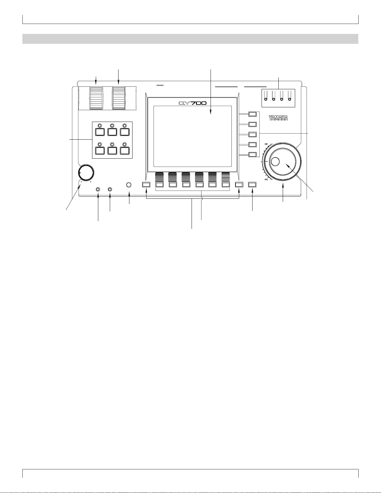
Top panel
2. ASSIGNABLE wheel 8. LCD display
1. PITCH wheel 13. MIDI Data monitors
3. Mode keys
PITCH ASSIGNABLE
SONG
VOICE
MAX
VOLUME
PATTERN
EFFECT
PLAYREC
UTILITY
DISK
CONTRAST
IN A
OUTPUT
SHIFT F1 F2 F3 F4 F5 F6 SHIFT EXIT
FOOT SWRL/MONO
MUSIC SEQUENCER
IN B
MIDI
OUT BOUT A
IN A
OUT BOUT AIN B
MIDI
12. Direct Cursor
keys
15. Data dial
14. Shuttle dial
4. VOLUME control
6. REC (recording) indicator
5. CONTRAST control
7. PLAY indicator
11. EXIT key
10. Function keys
9. SHIFT key
1. PITCH wheel
This controller is used to continuously modify the pitch or tone etc. while you play. The controller will return to the center position when you
release it. (→ p.290)
2. ASSIGNABLE wheel
This controller is used to continuously modify the tone etc. while you play. You can specify ho w this controller will affect the sound. (→ p.290)
3. Mode keys
Use these buttons to switch between modes.
s key
Switch to Song mode. (→ p.70)
p key
Switch to Pattern mode. (→ p.198)
u key
Switch to Utility mode. (→ p.288)
v key
Switch to Voice mode. (→ p.168)
e key
Switch to Effect mode. (→ p.188)
d key
Switch to Disk mode. (→ p.302)
12
Page 14

SETUP
4. VOLUME control
Use this to adjust the volume of the output jacks and the headphone jack.
5. CONTRAST control
Use this to adjust the contrast of the display.
6. REC (recording) indicator
This indicator will light when the e key is pressed, indicating that you are in recording mode.
7. PLAY indicator
During playback, this indicator will blink in time with the tempo.
8. LCD display
Various types of infor mation are displayed in this 320 x 240 pixel backlit liquid crystal display. The time after which the backlight will
automatically turn off can be set in Utility mode. (→ p.289)
9. s key
This button works in conjunction with other keys to perform various functions.
10.1–6 function keys
Use these keys to select from the menu that appears in the bottom line of the screen.
11.e key
This key moves from a sub mode or page display to the next higher level in the command hierarchy.
12.d [D1] –d [D5] direct keys
Use these keys to move the cursor to the setting items that are shown in the right side of the display.
13.MIDI Data monitors
The corresponding indicator will blink when MIDI data is transmitted or received at the four MIDI connectors (IN-A, IN-B, OUT-A, OUT-B).
This provides a way to confirm MIDI communications.
(Note) Since MIDI Clock messages are normally being transmitted, the MIDI OUT-A/B indicators will be blinking lightly.
14.Shuttle dial
Use this to fast-forward or rewind songs or patterns. Depending on the angle to which you rotate the dial, the speed of fast-forward or rewind
will change in four steps.
15.Data dial
Use this to select voices or to continuously increase/decrease a numerical value.
13
Page 15

SETUP
22. Decrement key, Increment key
19. Locate keys 20. Track keys
17. EDIT key
16. Sequencer keys 18. JOB key
EDIT JOB
LOC 2LOC 1
SHIFT
CAPS
ON
BASS
SECTION
#
F
OCT
OCT
DOWN
UP
b
G
ORG
BASS
_
!
E
A
MLK
FGAB C
B C D E F G H
#
#
CBA
A
G
b
b
B
A
S
#
?
N
c
(
D
)
E
C#D
DbE
%
D
#
b
&
add9
M7
M7
M
TRACK
DOWN
7
7
(9)
REST
#
5)
(
b
5)
(
TRACK
UP
SOLOMUTE
TIE
#
(
9)
7
b
(
9)
7
_
UTSRQPO
(9)
6
7
6
21. Cursor keys 23. Numeric keypad
-1 +1
a
b
(
13
)
HGF
7
(13)
7
/
(9)
add9
7
sus4
7
sus4
c
(9)
mM7
m7
m
m6
m7
YESNO
DEL
SPACE
JI
(11)
m7
OCT
OCT
3
#
DOWN
(
11)
7
YX
m7
UP
ZWV
dim
aug
(b5
)
789
456
123
0
3
-
24. Enter key26. Microkeyboard25. Octave keys 25. Octave keys
16.Sequencer keys
Use these keys to playback or record songs, patterns, and phrases. The layout of the buttons is similar to that of a conventional tape recorder.
t (Top) Return to the first measure of a song or pattern.
r (Rewind) Rewind the playback measure.
f (Forward) Advance the playback measure.
e (Recording) Enter recording standby mode.
s (Stop) Stop playback/recording.
p (Play) Begin playback/recording.
17.e key
Switch to Song Edit (→ p.129) or Phrase Edit (→ p.254).
18.j key
Access the Song jobs (→ p.138) or Pattern jobs (→ p.256).
19.1 (Locate 1) key
2 (Locate 2) key
In Song mode, these keys are used to move to a pre viously specified measure. Use s + 1/2 to store the current measur e in the
corresponding locate key.
14
Page 16

SETUP
20.Track keys
Use these keys to change the currently selected track, or to mute or solo specific tracks.
d key These keys switch the currently selected track.
u key
m key This mutes the playback of the currently selected track. Press the key once again to un-
mute the track.
s key This mutes the playback of all tracks other than the selected track. Press the key once
again to restore playback of the other tracks. Use this button when you want to hear only
the selected track.
21.Cursor keys
Use these keys to move the cursor location within the display.
22.n (Decrement) key
y (Increment) key
In various setting displays you can use these buttons to increase (increment) / decrease (decrement) values, or switch settings on/off. These
keys are also used to reply YES or NO to an “Are you sure?” prompt.
23.Numeric keypad
Use these to enter numerical values or note values.
24.e (Enter) key
Use this key to finalize a number entered by the numeric keypad, to enter the job selected by the cursor, or to execute a job etc.
25.Octave keys
These keys modify the pitch of the microkeyboard in steps of an octave.
In addition, the left octave button sets On Bass or Original Bass for a chord, and the right octave button sets chord Syncopation.
d[OCT DOWN] (Octave Down) key Lowers the pitch of the keyboard buttons in one-octave steps.
u[OCT UP] (Octave Up) key Raises the pitch of the keyboard buttons in one-octave steps.
26.Microkeyboard
These function as a keyboard for entering your performance. They are not sensiti ve to v elocity or aftertouch. The microk eyboard are also used
to specify chords and pattern sections, and to input characters.
15
Page 17
SETUP
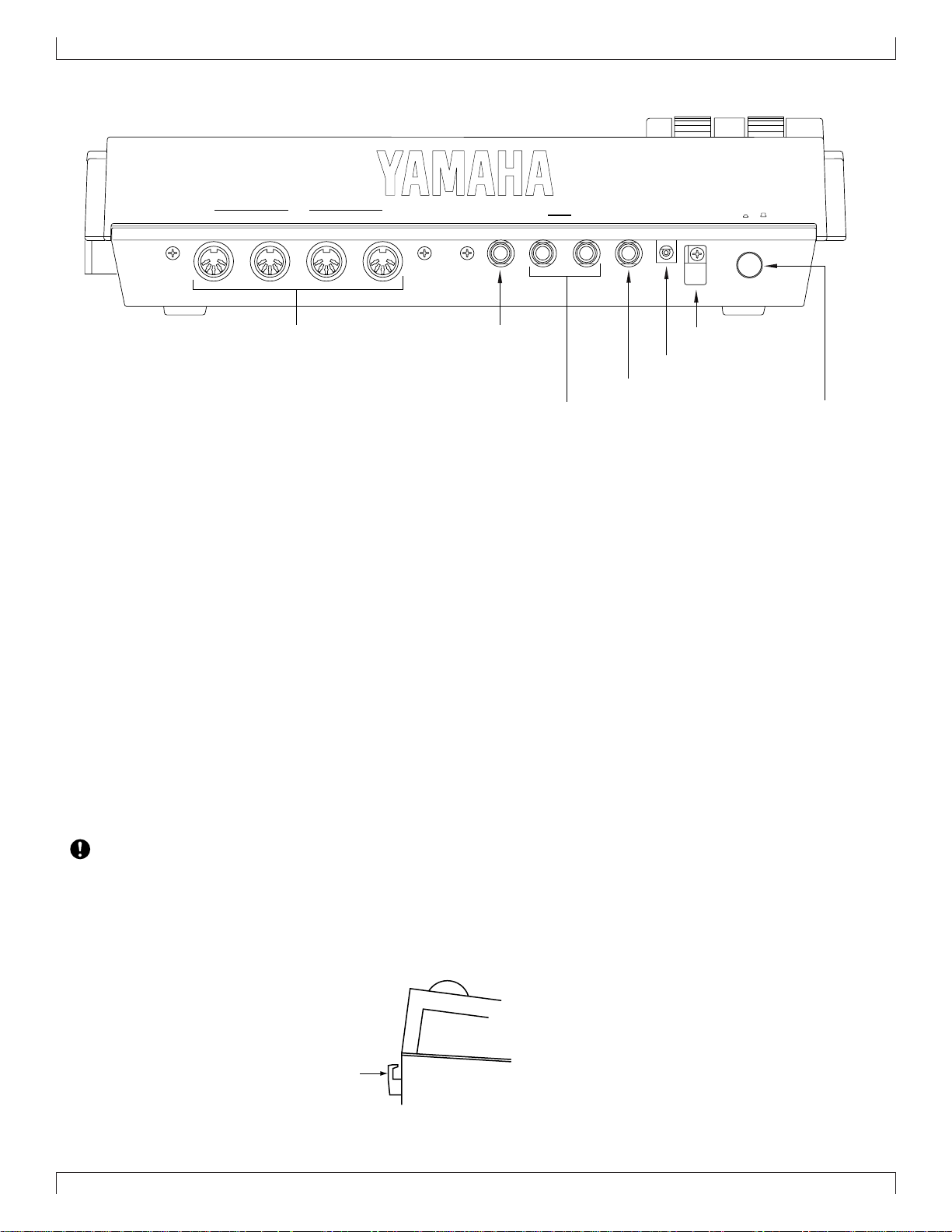
Rear panel
MIDI
1. MIDI connectors
IN-AIN-BOUT-AOUT-B
2. FOOT SW (Foot switch) jack
OUTPUT
INDCPHONESL/MONORSWFOOT
6. Cable clip
ON
POWER
OFF
5. DC IN (Power supply) jack
4. PHONES (Headphones) jack
3. OUTPUT jacks
7. POWER switch
1. MIDI connectors
These connectors are used to connect external MIDI devices via a MIDI cable. There are four MIDI connectors: IN-A, IN-B, OUT-A, and
OUT-B. IN-A and IN-B are inputs, and OUT-A and OUT-B are outputs. (→ p.20)
2. FOOT SW (Foot switch) jack
A foot switch (FC4, FC5: option) can be connected to this jack. A connected foot switch can be used during performance as a sustain pedal or
as a start/stop switch. (→ p.290)
3. OUTPUT jacks
These jacks are for line connections to powered speakers or a mixer. When playing in stereo, connect both jacks. When playing in mono,
connect the L/MONO jack. (→ p.19)
4. PHONES (Headphones) jack
A set of headphones with a stereo phone plug can be connected to this jack. (HPE-170 or other Yamaha recommended headphones: impedance
8 – 150 ohms.) The headphone volume is adjusted by the Volume control. (→ p.19)
5. DC IN (Power supply) jack
Connect the included PA-5B AC adaptor to this jack. (→ p.18)
• Before connecting the AC adaptor, make sure that the power switch of the QY700 is turned off. First connect the AC adaptor
to the power supply jack, and then plug it into an AC outlet.
• Use only the included PA-5B AC adaptor. Using other AC adaptors will cause malfunctions. Also, be sure to unplug the AC
adaptor from the AC outlet if you will not be using the unit for an extended period of time.
6. Cable clip
Wrap the A C adaptor power cable around this clip as shown in the diagram. This will decrease the possibility of the power cable being pulled
out accidentally.
Cable clip
7. POWER switch
This switch turns the power on/off. The power is on when the switch is pressed in. (→ p.18)
16
Page 18
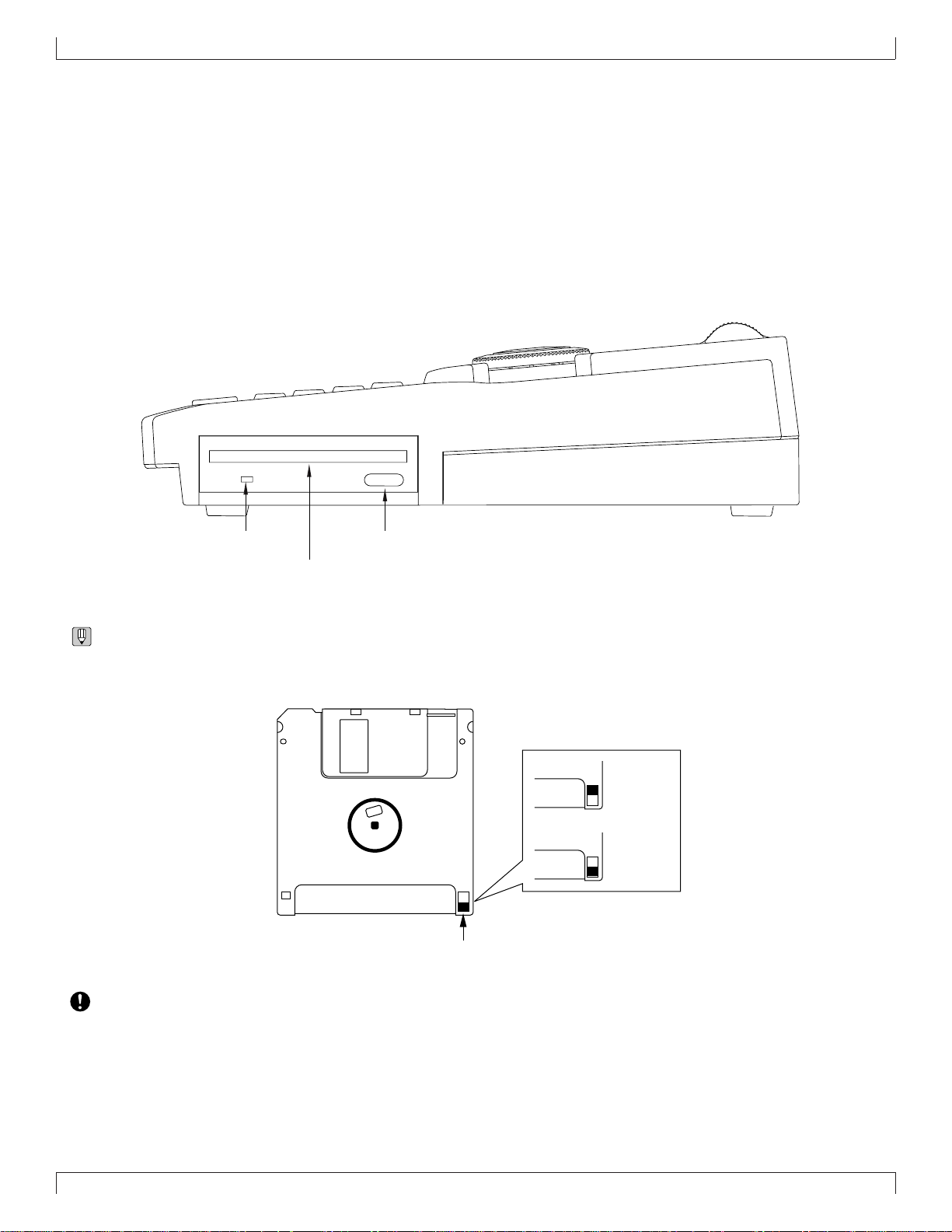
Floppy disk drive
1. Floppy disk slot
This is where floppy disks are inserted for loading or saving data. 3.5 inch 2HD (MF2HD) or 2DD (MF2DD) floppy disks can be used. (→
p.302)
2. Disk-in-use indicator
This indicator will light while data is being read from or written to the floppy disk. Never attempt to remo ve the disk while this indicator is lit.
3. Eject button
Press this button to remove the floppy disk. Disks must be inserted or remov ed gentl y and f irmly, and only while the access indicator is dark.
SETUP
2. Disk-in-use indicator 3. Eject button
1. Floppy disk slot
• The back of a floppy disk contains a write protect tab as shown in the following illustration. When this tab is in the downward position (with
the window open), it will not be possible to modify , ad d, or delete data. When you wish to protect important data, you should lea v e the tab
in this position.
Write permit
Write prohibit
Write protect tab
• Be aware that Yamaha can make no guarantee regarding data damage that results from improper use.
17
Page 19
SETUP
2. Connections
In order to use the QY700, the included AC adaptor and an amp system etc. must be connected. If you use external MIDI devices or controllers, these
must also be connected.
This sections explains how to make these connections.
• Be sure to turn off the power before making any connections. If you make connections while the power is on, you risk damag-
ing external equipment such as the amp or speakers.
Power supply connections
1. Make sure that the power switch of the QY700 is turned off, and connect the included AC adaptor (PA-5B) to the power supply jack.
2. Plug the AC adaptor into an AC outlet, and turn on the QY700 power switch.
• Use only the included PA-5B AC adaptor. Using other AC adaptors will cause malfunctions. Also, be sure to unplug the AC
adaptor from the AC outlet if you will not be using the unit for an extended period of time.
18
Page 20
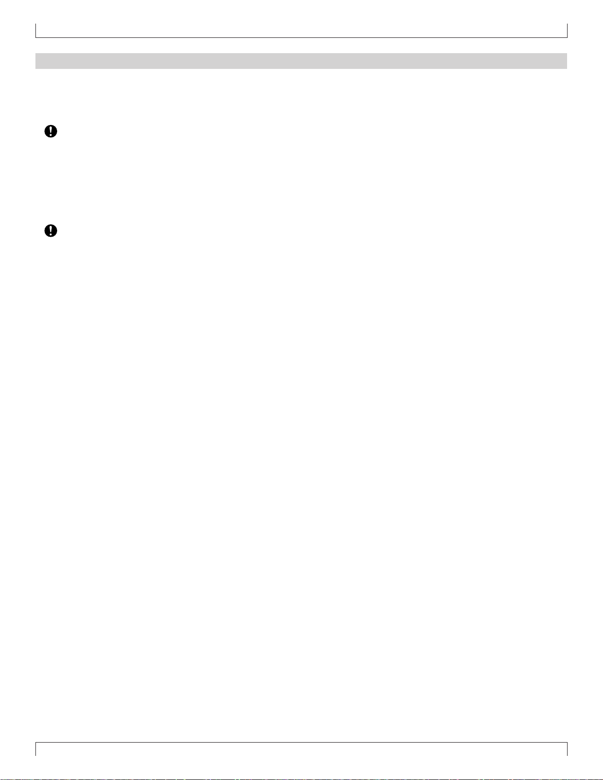
Audio equipment connections
To output the sound of the QY700, connect an amp or mixer to the output jacks.
Connection to powered speakers
Connect two powered speakers (left and right) to the output jacks (L/MONO, R).
If you are connecting only one powered speaker, use the L/MONO jack.
SETUP
OUTPUT
INDCPHONESL/MONORSWFOOT
POWER
ON
OFF
Connection to a mixer
Connect the output jacks (L/MONO, R) to two channels of the mixer . T he channel connected to the L/MONO jack should be panned left, and
the channel connected to the R jack should be panned right.
Make the same type of connections if you are connecting the QY700 to an MTR or cassette deck.
2
2
2
2
2
2
2
2
2
2
2
2
2
2
2
2
6
6
0
0
5
5
6
6
0
5
6
0
5
6
0
6016
6016
5
6
0
5
6016
6016
6016
6016
6016
6016
6016
6016
6016
6016
6016
6016
6016
6016
6
6
6
0
0
0
5
5
5
10
10
10
0
0
0
5
5
5
10
10
10
20
20
20
STRST ST
0
5
6
0
5
6
0
5
6
0
5
6016
6016
6016
6016
6016
6016
6016
6016
6016
6016
6
6
6
0
0
0
5
5
5
10
10
10
0
0
0
5
5
5
10
10
10
20
20
20
OUTPUT
6016
6016
6016
6016
6016
6016
6016
6016
6016
6016
6016
6016
6016
6016
6016
6016
6016
6016
6016
6016
6016
6016
6016
6016
6016
6016
6016
6016
6016
6016
POWER
ON
INDCPHONESL/MONORSWFOOT
OFF
6
0
5
10
0
5
10
20
6016
6016
6016
6016
6016
6016
6016
6016
6016
6
6
6
6
0
0
0
0
5
5
5
5
10
10
10
10
0
0
0
0
5
5
5
5
10
10
10
10
20
20
20
20
1 2 4 5 6 7 8 9 10 12 13 14 15 16
6016
6016
6016
6016
6016
6016
6016
6016
6016
6016
6016
6016
6016
6016
6016
6016
6016
6016
6016
6016
6016
6016
6016
6016
6016
6016
6016
6
6
0
0
5
5
10
10
0
0
5
5
10
10
20
20
6016
6016
6016
6016
6016
6016
6016
6016
6016
6016
6016
6016
6016
6016
6016
6016
6016
6016
6016
6016
6016
6016
6016
6016
6016
6
6
6
6
0
0
0
0
5
5
5
5
10
10
10
10
0
0
0
0
5
5
5
5
10
10
10
10
20
20
20
20
6016
6016
6016
6016
6016
6016
6016
6016
6016
6016
6016
6016
6016
6016
6016
6016
6016
6016
6016
6016
6016
6016
6016
6016
6016
6016
6016
6016
6016
6
6
6
0
0
0
5
5
5
10
10
10
0
0
0
5
5
5
10
10
10
20
20
20
Using headphones
If you are using headphones, connect them to the rear panel PHONES (headphones) jack.
When using headphones, adjust the volume to an appropriate level that will not harm your hearing.
• Do not connect the output jacks of the QY700 to the mic input jacks of an amp or cassette deck etc. If the y are connected to mic
inputs, the sound quality may be impaired, and the device may be damaged. Also, when connecting the QY700 to a mixer or
similar device, set the mixer channels to the Line Input position.
19
Page 21
SETUP
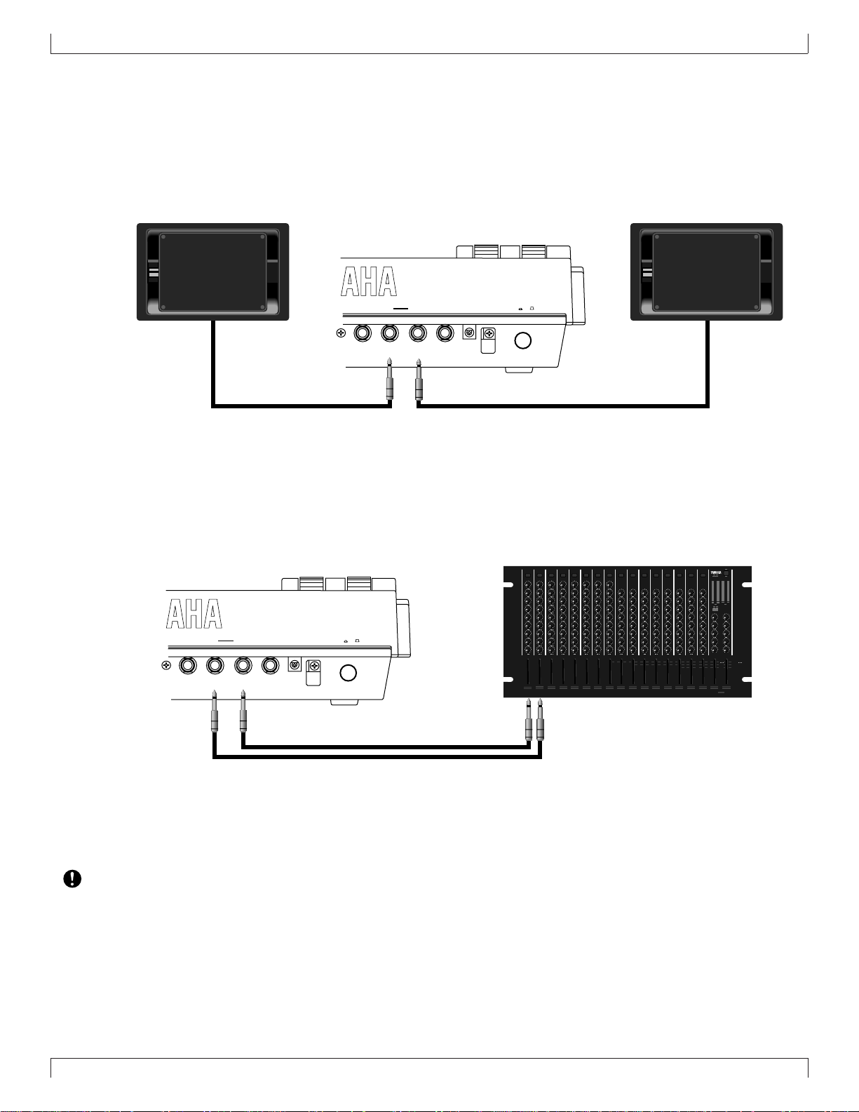
Connecting a foot switch
When using a separately sold FC4 or FC5 foot switch, insert the foot switch plug into the foot switch jack located on the rear panel.
FC4 or FC5
OUTPUT
Connecting external MIDI devices
Connecting a MIDI keyboard
Realtime recording or fingered chord input will be easier if you use a MIDI keyboard.
Use a MIDI cable to connect the MIDI OUT of the external MIDI keyboard to the MIDI IN-A or IN-B connector on the rear panel.
MIDI
IN-AIN-BOUT-AOUT-B
POWER
ON
INDCPHONESL/MONORSWFOOT
OFF
ABCD
MIDI
OUT
Connecting a tone generator module
QY700 song and pattern playback data can be used to play an external tone generator module.
Use a MIDI cable to connect the MIDI OUT -A or OUT-B connector on the rear panel to the MIDI IN connector of the external MIDI device.
MIDI IN
MUTE/
SOLO
ENTER
EXIT
PART
ALL
SELECT
VALUE
XG
TG300B
C/M
PERFORM
PLAY EDIT
UTIL EFFECT
MODE EQ
MIDI
IN-AIN-BOUT-AOUT-B
A/D
INPUT
PHONES POWER/VOL
PUSH ON/OFF
PART MIDI BANK/PGM# VOL EXP PAN REV CHO VAR KEY
20
Page 22
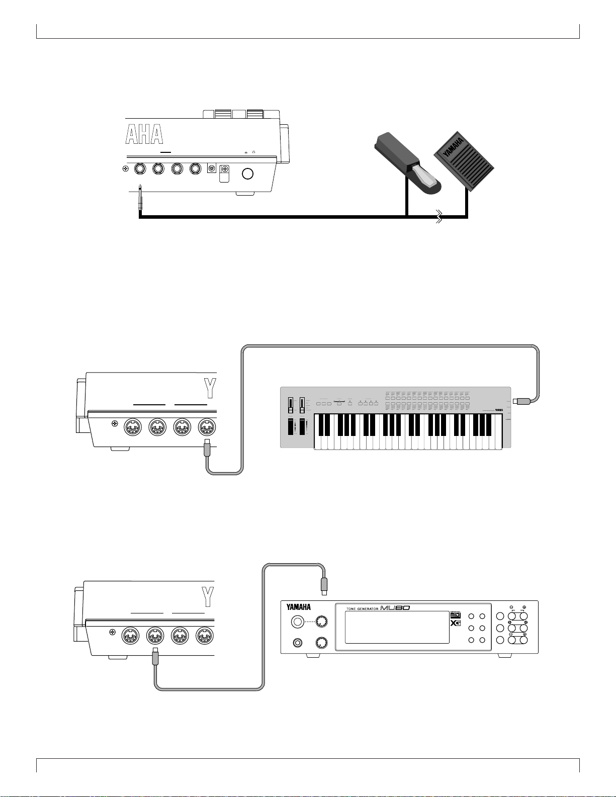
Connecting an MTR (multi-track recorder)
Since the QY700 implements MTC (MIDI Time Code) and MMC (MIDI Machine Control), you can produce music while synchronized to an
MTC- or MMC-compatible multi-track recorder.
Since the QY700 does not output MTC, you will need a device that is able to output MTC (such as the Yamaha MD4) if you wish to use MTC
for synchronization. In this case, use a MIDI cable to connect the MIDI IN-A or IN-B connector of the QY700 to the MIDI OUT connector of
the external device. MTC messages will be transmitted from the external device to the QY700, and the QY700 will synchronize to the clock
of the external device.
If you wish to remotely control operations such as start/stop and fast-forward/rewind on an external MMC-compatible device, use a MIDI
cable to connect the MIDI OUT-A or OUT-B connector of the QY700 to the MIDI IN connector of the external device. MMC messages will
be transmitted from the QY700 to the external device, and the QY700 will remotely control the external device.
In this case, set MIDI Sync to “MTC:MIDI-A” or “MTC:MIDI-B” in the MIDI page of Utility mode. (→ p.291)
Synchronizing the QY700 by MTC from an external device
IN A
OUT BOUT A
IN B
FOOT SWRL/MONO
PITCH ASSIGNABLE
SONG
VOICE
MAX
VOLUME
SHIFT
CAPS
OCT
OCT
DOWN
UP
ON
ORG
BASS
BASS
_
E
A
SECTION
#
F
G
!
MLK
FGABC
B C D E F G H
OUTPUT
PATTERN
UTILITY
EFFECT
DISK
SHIFT F1 F2 F3 F4 F5 F6 SHIFT EXIT
PLAYREC
CONTRAST
EDIT
JOB
LOC 2LOC 1
(
#
E)D
#
CBA
A
C#D
G
b
b
b
B
A
DbE
c
S
%
&
?
D
MIDI
IN A
MUSIC SEQUENCER
TRACK
TRACK
DOWN
UP
SOLOMUTE
REST
TIE
#
b
#
#
(
13
)
HGF
(
9)
5)
(
7
7
7
b
(
9)
(13)
b
b
5)
(
7
7
7
_
/
UTSRQPO#N
(9)
(9)
(9)
add9
add9
6
7
M7
6
7
M7
M
m
OUT BOUT AIN B
MIDI
-1 +1
789
YESNO
456
123
DEL
SPACE
a
JI
(11)
-
0
sus4
7
m7
OCT
OCT
3
3
#
DOWN
UP
11)
(
7
sus4
c
ZWV
YX
(9)
dim
mM7
m7
aug
(b5
)
m6
m7
m7
MIDI IN-A
or IN-B
SETUP
MIDI OUT
MTR
(MTC,MMC-compatible)
Controlling an external device via MMC from the QY700
FOOT SWRL/MONO
OUTPUT
MUSIC SEQUENCER
PITCH ASSIGNABLE
PATTERN
UTILITY
SONG
EFFECT
VOICE
DISK
MAX
VOLUME
SHIFT F1 F2 F3 F4 F5 F6 SHIFT EXIT
PLAYREC
CONTRAST
TRACK
EDIT
JOB
DOWN
LOC 2LOC 1
REST
SHIFT
CAPS
(
#
#
#
#
E)D
#
CBA
5)
(
A
F
C#D
G
OCT
UP
b
b
b
B
G
A
ORG
BASS
_
!
?
MLK
FGABC
B C D E F G H
7
b
b
5)
(
DbE
7
c
S
%
&
(9)
add9
M7
D
M7
M
OCT
DOWN
ON
BASS
E
A
SECTION
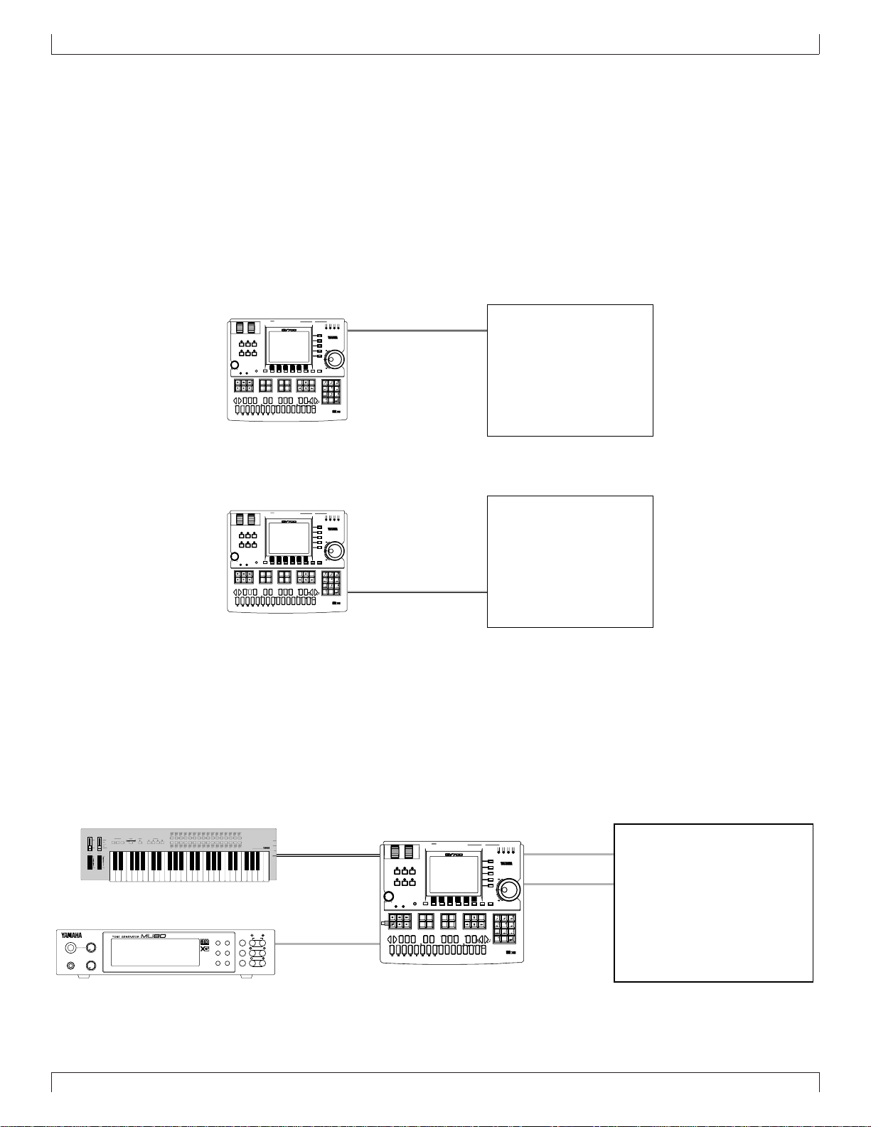
Connecting two or more devices
Since the QY700 provides two sets of MIDI connectors, you can connect two or more MIDI devices.
In the example below , the rear panel MIDI IN-A is connected to a MIDI ke yboard, the MIDI OUT -A to a tone generator module, and MIDI INB and OUT-B are connected to an MTR.
If you use MTC or MMC to control an MTR, set the Utility mode MIDI page MIDI Sync setting to “MTC:MIDI-B.” (→ p.291)
If you wish to use the MIDI keyboard to record parts which use the tone generator module, set the Utility mode MIDI page Echo Back setting
to “RecMonitor.” (→ p.292)
ABCD
MUTE/
PART
PLAY EDIT
ALL
XG
TG300B
C/M
PERFORM
UTIL EFFECT
MODE EQ
SOLO
ENTER
SELECT
EXIT
VALUE
A/D
INPUT
PHONES PO WER/VOL
PUSH ON/OFF
PART MIDI BANK/PGM# VOL EXP PAN REV CHO VAR KEY
IN A
IN B
MIDI
-1 +1
TRACK
YESNO
UP
SOLOMUTE
TIE
DEL
SPACE
a
#
b
(
13
)
HGF
JI
(
9)
(11)
7
7
7
sus4
m7
OCT
OCT
3
#
DOWN
UP
b
(
11)
(
9)
(13)
7
7
7
sus4
c
_
/
ZWV
UTSRQPO#N
YX
(9)
(9)
(9)
dim
add9
mM7
6
7
m7
aug
(b5
)
6
7
m
m6
m7
m7
MIDI OUT
MIDI IN
OUT BOUT A
IN A
OUT BOUT AIN B
MIDI
789
MIDI OUT-A
456
123
or OUT-B
-
0
3
MIDI IN-A
MIDI OUT-A
PITCH ASSIGNABLE
PATTERN
SONG
EFFECT
VOICE
MAX
VOLUME
SHIFT
CAPS
#
F
OCT
OCT
DOWN
UP
b
G
ON
ORG
BASS
BASS
_
!
MLK
E FGABC
A
SECTION
B C D E F G H
FOOT SWRL/MONO
OUTPUT
MUSIC SEQUENCER
UTILITY
DISK
SHIFT F1 F2 F3 F4 F5 F6 SHIFT EXIT
CONTRAST
PLAYREC
TRACK
JOB
EDIT
DOWN
LOC 2LOC 1
REST
(
#
#
E)D
#
CBA
A
C#D
G
7
b
b
B
b
A
DbE
7
c
S
%
&
?
(9)
add9
M7
D
M7
M
MTR
(MTC,MMC-compatible)
MIDI IN
IN A
OUT BOUT A
IN B
MIDI
-1 +1
TRACK
YESNO
UP
SOLOMUTE
TIE
DEL
SPACE
a
#
b
#
(
13
)
HGF
JI
9)
(
(11)
(
5)
7
7
7
sus4
m7
OCT
OCT
3
#
DOWN
UP
b
11)
(
9)
(
(13)
b
5)
(
7
7
7
sus4
c
_
/
ZWV
UTSRQPO#N
YX
(9)
(9)
(9)
dim
add9
mM7
6
7
m7
aug
(b5
)
6
7
m
m6
m7
m7
3
IN A
789
456
123
0
OUT BOUT AIN B
MIDI
-
MIDI IN-B
MIDI OUT-B
MIDI OUT
MIDI IN
MTR
(MTC/MMC-compatible)
21
Page 23

SETUP
3. Using the Style and Demonstration disk
Here’s how to use the included “STYLE & DEMONSTRATION” disk.
Contents of the disk
• The included disk contains “STYLE,” “DEMO 1” and
“DEMO 2.”
• “DEMO 1” and “DEMO 2” allow you to enjoy demo playback, and to playback songs while adjusting the Play Effects or Multi to experience the possibilities of the QY700.
• “STYLE” allows you to restore the factory settings of the
QY700.
Listening to the demo playback
• Here’s how to load a demo song file from disk and enjoy
the demo playback.
• When “DEMO 1” or “DEMO 2” is loaded from disk, all
internal memory will be rewritten by the demo playback data. If internal memor y contains any impor tant
data that you wish to keep , sav e the data bef ore loading the demo.
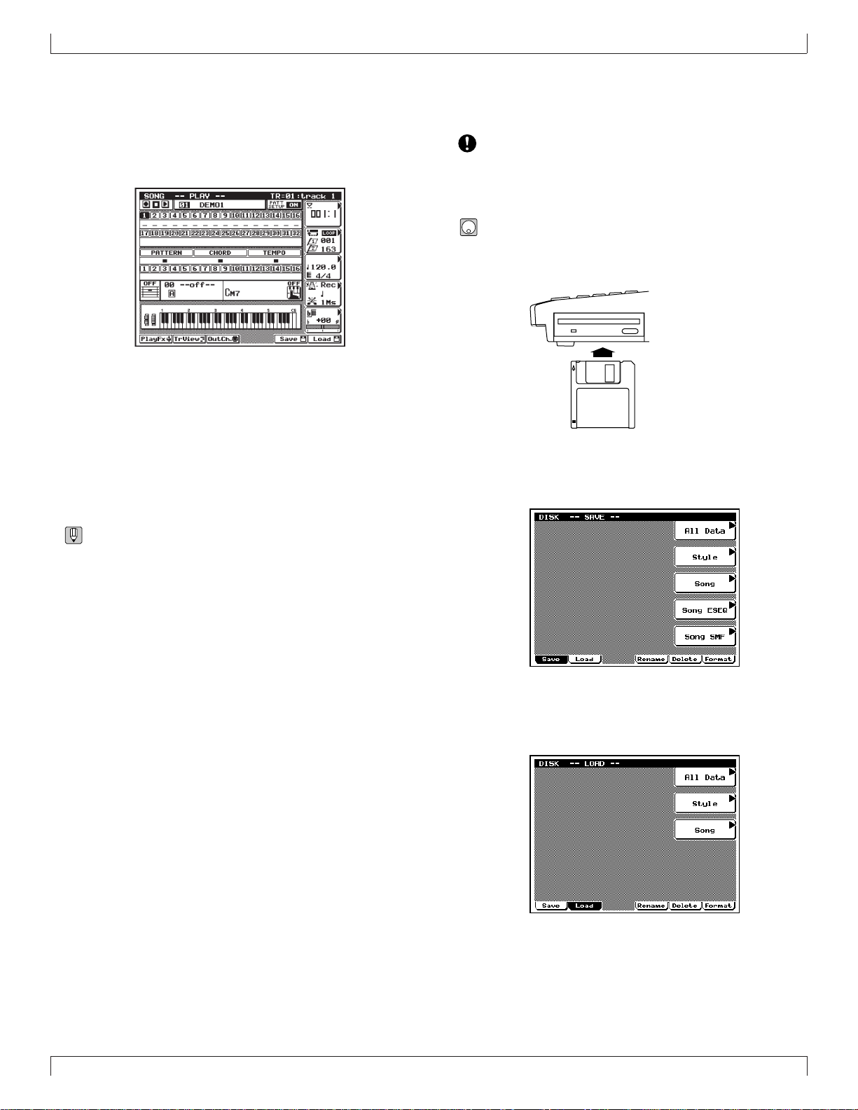
1. With the label facing upward, insert the disk into the
floppy disk slot.
▼ Insert the disk all the way until it clicks into place.
3. Press 2 (Load).
▼ You will enter Load sub-mode, and the top line of the dis-
play will indicate “DISK -- LOAD --”.
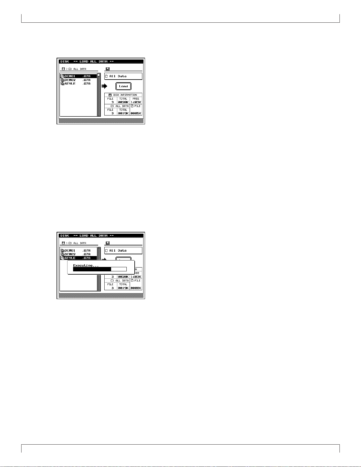
4. Press d [D1] (All Data).
▼ The Load All Data page will appear, and the f ilenames will
be displayed.
2. Press d.
▼ You will enter Disk mode.
5. Use the cursor keys / data dial to move the cursor to
“DEMO 1” or “DEMO 2” and press e.
▼ A message of “Are You Sure? (Y/N)” will appear, asking
whether it is OK to erase the data in internal memory and
load the data from disk.
• If you do not wish to erase the data currently in memory,
press n to halt loading. Then save the data in memory to
a disk, and perform the loading procedure once again. (→
p.307)
22
Page 24
SETUP
6. Press y.
▼ The display will indicate “Executing...” and the data will be
loaded.
7. Press s.
▼ You will return to the Song mode display.
8. Use the cursor keys to move the cursor to the song
number, and use the data dial, n/y or the numeric
keypad → e to set the song number to 01.
9. Press r to playback the demo song.
▼ Playback will begin, so use the volume control to adjust the
volume to a suitable level.
• Pressing s will stop playback.
Restoring the factory settings
• Here’s how to restore the QY700 to the factory settings.
• When you load “STYLE” from the disk, all internal
memory will be rewritten to the factory settings. If internal memory contains any data that you wish to keep,
save the data before loading the “STYLE” data.
1. With the label facing upward, insert the disk into the
floppy disk slot.
▼ Insert the disk all the way until it clicks into place.
2. Press d.
▼ You will enter Disk mode.
• By changing the song number in step 8 you can playback
other songs.
3. Press 2 (Load).
▼ You will enter Load sub-mode, and the top line of the dis-
play will indicate “DISK -- LOAD --”.
23
Page 25
SETUP
4. Press d [D1] (All Data).
▼ The Load All Data page will appear, and the f ilenames will
be displayed.
5. Use the cursor keys / data dial to move the cursor to
“STYLE” and press e.
▼ A message of “Are You Sure? (Y/N)” will appear, asking
whether it is OK to erase the data in internal memory and
load the data from disk.
• If you do not wish to erase the data currently in memory,
press n to halt loading. Then save the data in memory to
a disk, and perform the loading procedure once again. (→
p.307)
6. Press y.
▼ The display will indicate “Executing...” and the data will be
loaded.
24
Page 26

Chapter 1. BASIC CONCEPTS
This chapter explains the basic concepts that you need to kno w before use, such as the mode structure and the internal structure of
the QY700.
1
1. Mode structure ........................................... 26
2. Function tree .............................................. 34
3. How the QY700 is organized...................... 36
4. Sequencer block ........................................ 37
5. The tone generator block ........................... 43
6. Controller block .......................................... 46
7. Effect block................................................. 47
8. Basic operation .......................................... 51
9. Song creating procedure............................ 56
Page 27

BASIC CONCEPTS
Mode name Sub-mode name
Page name
Sub-page name
Special page name
1. Mode structure
About modes
• The many functions of the QY700 are grouped by type into
modes, sub-modes, and pages (see the diagram below).
When operating the QY700, you will arrive at the desired
function by first selecting the mode, then the sub-mode, and
finally the page.
• Modes are the largest division of functions. Use the Mode
buttons to switch between modes.
• Sub-modes are broad divisions of the functions within each
mode. If the bottom line of the display shows a menu shaped
like buttons, you can press the corresponding function button to select the desired sub-mode. In some cases, you will
enter a sub-mode by pressing the s, e, or j
keys.
• Pages contain groups of related parameters within a submode. If the bottom line of the sub-mode display shows a
tab-shaped menu, you can press the corresponding function
button to switch pages. In some sub-modes, you can select
sub-pages within a page, or move to a special page to make
settings.
Modes and sub-modes
The QY700 has the following modes and sub-modes.
■ Song mode
Here you can record or playback songs. (→ p.70)
The Auto-accompaniment functions allo w you to create music
efficiently.
Press s to enter this mode.
Mode
Sub-mode
Sub-mode
Page
Page
Page
Mode
Sub-mode
Sub-mode
Sub-page
Sub-page
Special page
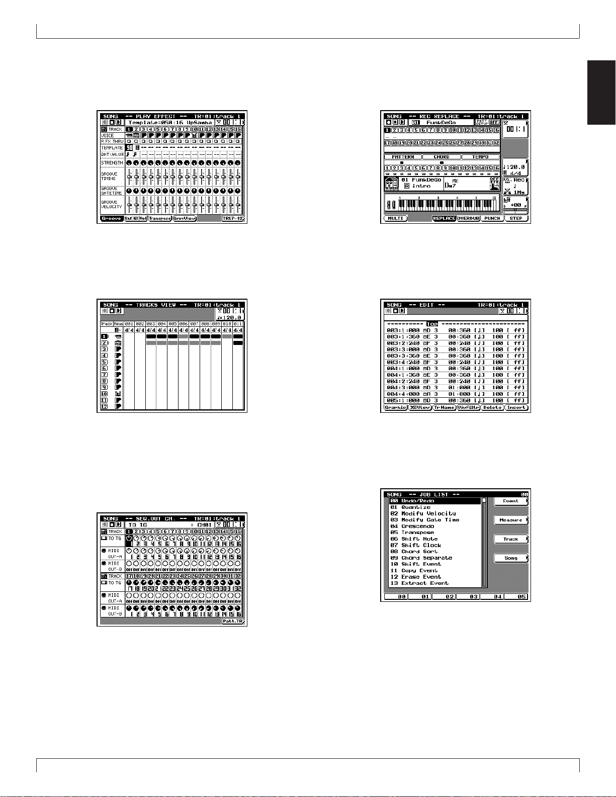
• The following example shows the Song (mode) Play Ef fect
(sub-mode) Groove Quantize (page) display.
Song Play
Here you can select and playback songs. (→ p.72)
This is the first sub-mode you will enter when you press s.
26
Chapter 1
Page 28
BASIC CONCEPTS
Play Effect
Here you can make temporary adjustments to the note timing
and dynamics for song playback. (→ p.80)
In Song Play, press 1 (PlayFx) to enter this sub-mode.
T rack View
This display shows the measures in which data has been input
in each track. (→ p.100)
In Song Play, press 2 (TrView) to enter this sub-mode.
Song Recording
Here you can record song data onto the tracks of a song. (→
p.106)
In Song Play, press e to enter this sub-mode.
Song Edit
Here you can modify the song data of a song, or insert new
data. (→ p.129)
In Song Play, press e to enter this sub-mode.
1
Out Channel
Here you can set the output channel for each of the tracks and
patterns which make up the song, determining how they will
be transmitted to the tone generator block and to the MIDI OUT
connectors. (→ p.103)
In Song Play, press 3 (OutCh.) to enter this sub-mode.
Song Job
Here you select and execute song jobs to edit or modify a song.
(→ p.138)
In Song Play, press j to enter this sub-mode.
Chapter 1
27
Page 29
BASIC CONCEPTS
■ Voice mode
Here you can make tone generator settings such as voice and
volume for each part, determining how each part will sound
when the song is played back. (→ p.168)
Press v to enter this mode.
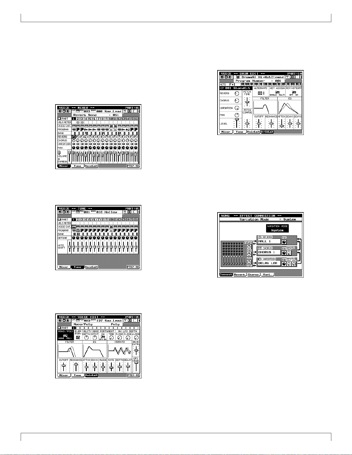
Mixer
Here you can make tone generator settings such as voice, pan
and volume for each part. (→ p.170)
In Voice mode, press 1 (Mixer) to enter this sub-mode.
Tune
Here you can transpose or tune each part. (→ p.174)
In Voice mode, press 2 (Tune) to enter this sub-mode.
Drum Setup Edit
Here you can edit Drum Setup 1 and 2 to indirectly modify
drum voices. (→ p.182)
After selecting Drum Setup 1 or 2 as the voice category in Voice
mode, press 4 or 5 to enter this sub-mode.
■ Effect mode
Here you can make settings for the effects used in a song. (→
p.188)
Press e to enter this mode.
Effect Connection
Here you can select the way in which the Variation effect is
connected. (→ p.190)
In Effect mode, press 1 (Connect) to enter this sub-mode.
Voice Edit
Here you can modify parameter values for each part to modify
the voice. (→ p.176)
In Voice mode, press 3 (V oicEdit) to enter this sub-mode .
28
Chapter 1
Page 30
BASIC CONCEPTS
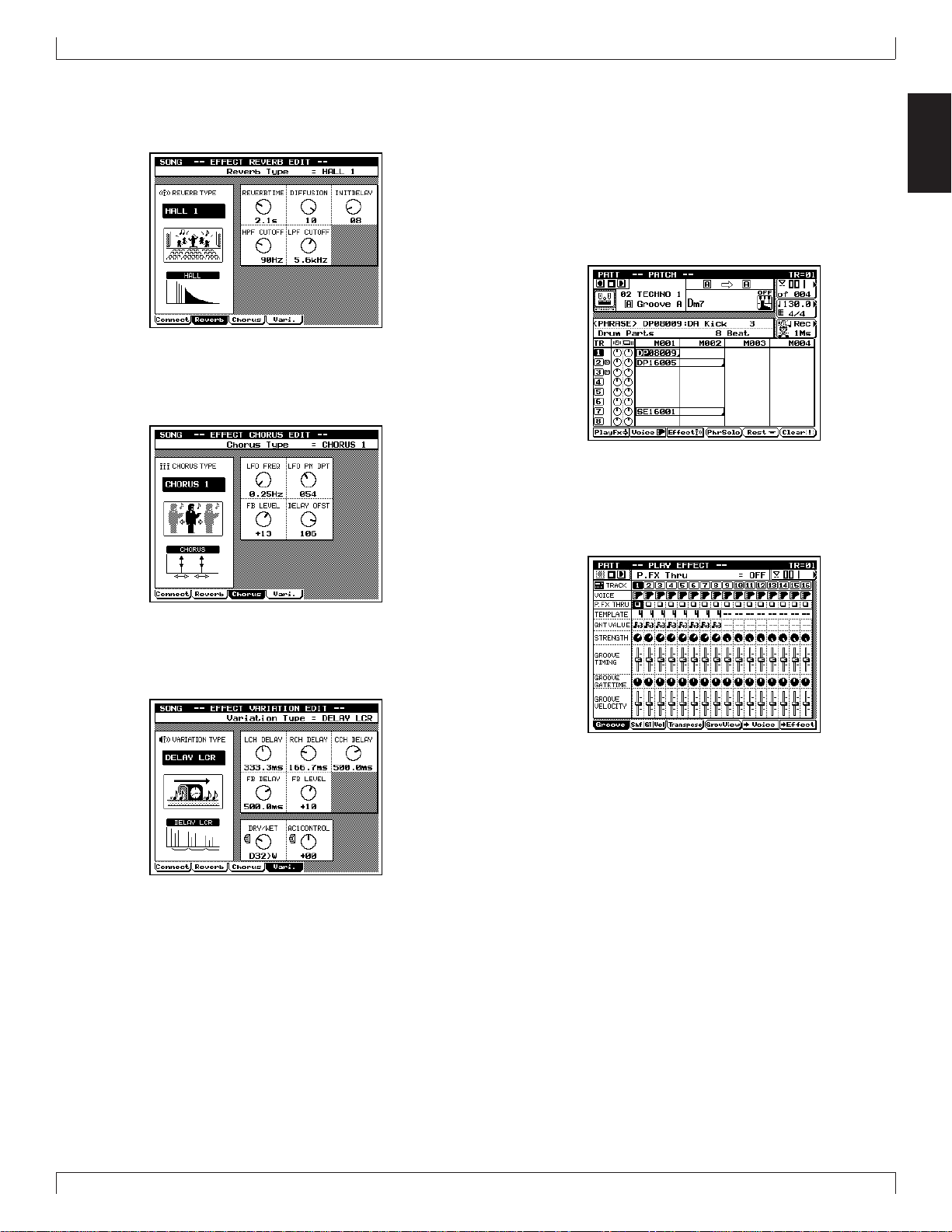
Effect Reverb Edit
Here you can make settings for the Reverb effect. (→ p.193)
In Effect mode, press 2 (Reverb) to enter this sub-mode.
Effect Chorus Edit
Here you can make settings for the Chorus effect. (→ p.193)
In Effect mode, press 3 (Chorus) to enter this sub-mode.
■ Pattern mode
Here you can create and playback patterns or phrases. (→ p.200)
Press p to enter this mode.
Patch
Here you can select and playback patterns. Patterns are created
by assigning phrases to each track of the pattern. (→ p.200)
This is the sub-mode that you will enter when you first press
p .
Play Effect
Here you can make temporary changes in the timing and dynamics of pattern playback. (→ p.212)
In Patch, press 1 (PlayFx) to enter this sub-mode.
1
Effect V ariation Edit
Here you can make settings for the Variation effect. (→ p.193)
In Effect mode, press 4 (Vari.) to enter this sub-mode.
Chapter 1
29
Page 31

BASIC CONCEPTS
Pattern V oice
Here you can make tone generator settings such as voice or
volume for each pattern track. (→ p.225)
In Patch, press 2 (Voice) to enter this sub-mode.
Pattern Effect
Here you can make settings for the effects used in the pattern.
(→ p.239)
In Patch, press 3 (Effect) to enter this sub-mode.
Phrase Edit
Here you can modify or insert data in a Preset Phrase or User
Phrase. (It is possible to enter Edit mode even with a preset
phrase, but the data cannot be edited.) (→ p.254)
In Patch, move the cursor to User Phrase, and press e to
enter this sub-mode.
Pattern Job
Here you can select and execute jobs to edit or modify a pattern. (→ p.256)
In Patch, press j to enter this sub-mode.
Phrase Recording
Here you can record musical data into the selected User Phrase.
(→ p.247)
In Patch, move the cursor to User Phrase and press e to enter
this sub-mode.
30
Chapter 1
Page 32

BASIC CONCEPTS
■ Utility mode
Here you can make basic settings for the QY700 and MIDIrelated settings. (→ p.288)
Press u to enter this mode.
System
Here you can make basic settings for the QY700 such as master tuning and controller settings. (→ p.289)
In Utility mode, press 1 (System) to enter this sub-mode.
MIDI
Here you can make MIDI-related settings. (→ p.291)
In Utility mode, press 2 (MIDI) to enter this sub-mode.
MIDI Filter
Here you can specify whether or not various categories of MIDI
message will be transmitted or received via the MIDI connectors. (→ p.293)
In Utility mode, press 3 (MIDI Fltr) to enter this submode.
Sequencer
Here you can make basic settings related to the sequencer block.
(→ p.295)
In Utility mode, press 4 (Seqencr) to enter this sub-mode.
1
Click
Here you can make basic settings for the click sound. (→ p.297)
In Utility mode, press 5 (Click) to enter this sub-mode.
Chapter 1
31
Page 33

BASIC CONCEPTS
Fingered Chord Zone
Here you can specify the range of the keyboard in which Fingered Chord will function. (→ p.299)
In Utility mode, press 6 (FngZone) to enter this sub-mode.
■ Disk mode
In this mode you can transfer data to and from the floppy disk.
(→ p.302)
Press d to enter this mode.
Save
Here you can save internal memory data to floppy disk. (→
p.307)
In Disk mode, press 1 (Save) to enter this sub-mode.
Rename
Here you can change the filename of a file on floppy disk. (→
p.312)
In Disk mode, press 4 (Rename) to enter this sub-mode.
Delete
Here you can delete a file from the floppy disk. (→ p.314)
In Disk mode, press 5 (Delete) to enter this sub-mode.
Load
Here you can load data from floppy disk into internal memory .
(→ p.310)
In Disk mode, press 2 (Load) to enter this sub-mode.
32
Chapter 1
Page 34

Format
Here you can format a floppy disk. (→ p.316)
In Disk mode, press 6 (Format) to enter this sub-mode.
BASIC CONCEPTS
1
Chapter 1
33
Page 35

BASIC CONCEPTS
2. Function tree
Song mode
sSong Play............................................................................. p.72
1Play Effect ............................................................... p.80
1Groove ......................................................... p.82
4Groov e V ie w .................................... p.82
5Copy Template ................................. p.89
2Clock Shift / Gate Time / Velocity............... p.90
3Transpose ..................................................... p.94
4Drum Table Edit .............................. p.97
2T rack V iew............................................................. p.100
3Out Channel........................................................... p.103
5Save Song .............................................................. p.307
6Load Song.............................................................. p.310
s+5 Save Song SMF....................................... p.307
s+6 Load Song ............................................... p.310
e Song Recording ..................................................... p.106
1Multi .......................................................... p.110
3Replace ...................................................... p.112
4Overdub ..................................................... p.112
5Punch ......................................................... p.118
6Step............................................................ p.120
eSong Edit ............................................................... p.129
1Graphic, Event List.................................... p.135
2XG V iew .................................................... p.132
3Track Name ............................................... p.132
4View Filter ................................................. p.133
5Delete......................................................... p.133
6Insert .......................................................... p.133
jSong Job ................................................................ p.138
00 Undo/Redo........................................................ p.141
01 Quantize............................................................ p.142
02 Modify Velocity ................................................ p.145
03 Modify Gate Time ............................................ p.147
04 Crescendo ......................................................... p.148
05 Transpose.......................................................... p.149
06 Shift Note.......................................................... p.150
07 Shift Clock........................................................ p.150
08 Chord Sort ........................................................ p.151
09 Chord Separate ................................................. p.152
10 Shift Event ........................................................ p.153
11 Copy Event ....................................................... p.154
12 Erase Event ....................................................... p.155
13 Extract Event .................................................... p.155
14 Thin Out............................................................ p.157
15 Time Stretch...................................................... p.158
16 Create Measure ................................................. p.158
17 Delete Measure ................................................. p.159
18 Copy Track ....................................................... p.160
19 Mix Track ......................................................... p.161
20 Clear Track ....................................................... p.162
21 Expand Backing................................................ p.162
22 Normalize Play Effect ...................................... p.163
23 Copy Song ........................................................ p.164
24 Clear Song ........................................................ p.164
25 Song Name ....................................................... p.165
Voice mode
v ........................................................................................... p.168
1Mixer ..................................................................... p.170
2Tune ....................................................................... p.174
3Voice Edit .............................................................. p.176
4Drum Setup 1 Edit................................................. p.182
5Drum Setup 2 Edit................................................. p.182
Effect mode
e ....................................................................................... p.188
1Effect Connection.................................................. p.190
2Effect Reverb Edit ................................................. p.193
3Effect Chorus Edit ................................................. p.193
4Effect Variation Edit .............................................. p.193
Pattern mode
p Patch.............................................................................. p.200
1Play Effect ............................................................. p.212
1Groove ....................................................... p.214
4Groov e V ie w .................................. p.214
2Clock Shift / Gate Time / Velocity............. p.217
3Transpose ................................................... p.219
4Drum Table Edit ............................ p.222
5Pattern Voice .............................................. p.225
6Pattern Effect ............................................. p.239
2Pattern Voice .......................................................... p.225
1Mixer ......................................................... p.227
2Voice Edit .................................................. p.232
3Drum Setup 3 Edit..................................... p.235
5Play Effect ................................................. p.212
6Pattern Effect ............................................. p.239
3Pattern Effect ......................................................... p.239
1Connection................................................. p.241
2Reverb........................................................ p.244
3Chorus........................................................ p.244
4Variation .................................................... p.244
5Play Effect ................................................. p.212
6Pattern Voice .............................................. p.225
34
Chapter 1
Page 36

BASIC CONCEPTS
4Phrase Solo ............................................................ p.208
6Phrase Table ............................................... p.209
5Rest ................................................................... p.208
6Clear ................................................................... p.208
e Phrase Recording................................................... p.247
4Replace ...................................................... p.252
5Overdub ..................................................... p.252
6Step............................................................ p.253
ePhrase Edit Change................................................ p.254
1Graphic / Event List................................... p.254
2XG V iew .................................................... p.254
4View Filter ................................................. p.254
5Delete......................................................... p.254
6Insert.......................................................... p.254
jPattern Job ............................................................. p.256
00 Undo/Redo........................................................ p.259
01 Quantize............................................................ p.260
02 Modify Velocity ................................................ p.261
03 Modify Gate Time ............................................ p.262
04 Crescendo ......................................................... p.263
05 Transpose.......................................................... p.263
06 Shift Note.......................................................... p.264
07 Shift Clock........................................................ p.265
08 Chord Sort ........................................................ p.265
09 Chord Separate ................................................. p.266
10 Shift Event ........................................................ p.267
11 Copy Event ....................................................... p.268
12 Erase Event ....................................................... p.269
13 Extract Event .................................................... p.269
14 Thin Out............................................................ p.271
15 Time Stretch...................................................... p.272
16 Copy Phrase...................................................... p.272
17 Mix Phrase........................................................ p.274
18 Append Phrase .................................................. p.275
19 Split Phrase ....................................................... p.276
20 Get Phrase......................................................... p.277
21 Put Phrase ......................................................... p.278
22 Clear Phrase...................................................... p.279
23 Phrase Name ..................................................... p.279
24 Clear Track ....................................................... p.280
25 Copy Pattern ..................................................... p.281
26 Append Pattern ................................................. p.282
27 Split Pattern ...................................................... p.283
28 Clear Pattern ..................................................... p.284
29 Pattern Name .................................................... p.284
30 Style Icon.......................................................... p.285
Utility mode
u ....................................................................................... p.288
1System ................................................................... p.289
2MIDI...................................................................... p.291
3MIDI Filter ............................................................ p.293
4Sequencer .............................................................. p.295
5Click ...................................................................... p.297
6Fingered Chord Zone............................................. p.299
Disk mode
d ........................................................................................... p.302
1Save........................................................................ p.307
2Load ....................................................................... p.310
4Rename.................................................................. p.312
5Delete..................................................................... p.314
6Format.................................................................... p.316
1
Chapter 1
35
Page 37

BASIC CONCEPTS
3. How the QY700 is organized
Four blocks
• The QY700 consists of four blocks: the sequencer block,
the tone generator block, the controller block, and the effect block.
Sequencer block (→ p.37)
• This block lets you create songs by recording/editing musical performances recorded from an external MIDI device
or from the controller block, and then plays back this data,
transmitting it to the tone generator block or to an external
MIDI tone generator as MIDI messages.
• The sequencer block can be operated in two modes: Song
mode (→ p.70) and Pattern mode (→ p.198).
• Using the Auto-Accompaniment function (→ p.37) allows
you to create music efficiently.
• By recording one track at a time to create a multi-track recording, you can create songs which use up to 32 tracks (up
to 48 tracks if you use the Auto-Accompaniment function).
• When songs or patterns are played back, the musical data is
output to the tone generator block and to the MIDI OUT
connectors. The output destination of the musical data can
be specified for each track by setting the Out Channel (→
p.103).
Tone generator block (→ p.43)
• This block produces sound in response to the MIDI messages that it receives from the sequencer block, controller
block, and from the MIDI IN connectors.
• Settings for this block can be made in Voice mode (→ p.168).
• This is a 32 part 32 note polyphonic multi-timbral XG-compatible tone generator.
MIDI IN
MIDI OUT
Effect block (→ p.47)
• This block processes the audio signal that is output from
the tone generator block, adding reverberation or ambiance
etc.
• This block provides three XG-compatible effects: reverb
effect, chorus effect, and variation effect.
• Settings for this block can be made in Effect mode (→
p.188).
How the blocks are connected
• The four blocks are connected as follows.
external MIDI device,
MIDI tone generator
external MIDI device,
MIDI keyboard
Sequencer block
MIDI messages
Tone Generator
MIDI
messages
Controller block
block
audio
signals
Effect block
audio
signals
Controller block (→ p.46)
• This block contains the microkeyboard, pitch wheel, assignable wheel, and foot switch that you use to perform, and
from which MIDI messages are transmitted to the sequencer
block and to the tone generator block.
• The functions of the pitch wheel, assignable wheel, and foot
switch can be set in Utility mode (→ p.288).
• The output destination of the musical data transmitted from
the controller block is specified by the Keyboard T rack setting (→ p.74) of the sequencer block. The musical data is
output as specified by the Out Channel setting of the keyboard track, either to one of the parts of the tone generator
or to the MIDI OUT connectors.
36
Chapter 1
Page 38

4. Sequencer block
BASIC CONCEPTS
1. About the sequencer block
• This block lets you create songs by recording/editing the
musical performance that is recorded from an external MIDI
device or from the controller block, and then plays back the
data, transmitting it to the tone generator block or to an external MIDI tone generator as MIDI messages.
• The sequencer block can be operated in two modes: Song
mode and Pattern mode.
• Using the Auto-Accompaniment function allo ws you to create song efficiently by joining together patterns and phrases.
Patterns and phrases will be explained below.
• By recording one track at a time to create a multi-track recording, you can create songs which use up to 32 tracks (up
to 48 tracks if you use the Auto-Accompaniment function).
• When songs or patterns are played back, the musical data is
output to the tone generator block and to the MIDI OUT
connectors. The output destination of the musical data can
be specified for each track by setting the Out Channel.
• “Tracks” are memory areas in which musical performances
are recorded. Musical data can be recorded, edited, and
played back independently for each track.
external MIDI device,
MIDI tone generator
external MIDI device,
MIDI keyboard
2. Auto-Accompaniment
• Auto-Accompaniment is a function that lets you specify
chords for the phrases or patterns created in Pattern mode,
creating an accompaniment that is played back automatically.
• The accompaniment created using the Auto-Accompaniment
function consists of three types of elements: phrases, patterns, and songs.
• “Phrases” are musical accompaniment phrases for a single
instrument, such as a rhythm pattern for the rhythm part, a
bass line for the bass part, or a chord backing for the guitar
part. Phrases are the smallest unit that makes up the accompaniment of a song.
• “Patterns” are created by joining two or more Phrases horizontally, or by joining up to 16 parts vertically to create an
accompaniment with drums, bass, and chord backing. While
phrases contain musical data for a single instrument, patterns combine two or more phrases to create a single backing pattern. Patterns are the basic unit with which the accompaniment of a song is created.
• In order to create the accompaniment for an entire song,
you will need to create different patterns for the various
parts of the song, such as the intro, theme, fill-ins, breaks,
and ending.
• Song mode provides a Pattern track in which patterns can
be arranged, and a Chord track in which chords can be arranged. When you place patterns and chords in these tracks
as appropriate for the changes in your song, the accompaniment patterns will automatically be converted for playback
with the chords you specify.
1
MIDI IN
MIDI OUT
Sequencer block
Song
Pattern
Phrase
MIDI messages
Tone Generator
MIDI
messages
Controller block
block
audio
signals
Effect block
audio
signals
Song
001 002 003 004 005 006 007 008 009 010 011 012 013 014 015 016 017 018
Track 1
Sequence
tracks
Pattern
track
Chord
track
Tempo
track
•
•
•
Track 32
Pattern number
Em7 Em7
Tempo=90 Tempo=96
Pattern
Phrase
Em7 • • • Am7 Bm7
Phrase number
• • •
Chapter 1
37
Page 39

BASIC CONCEPTS
16 16 beat : 16-beat phrases
08 8 beat : 8-beat phrases
34 3/4 beat : 3/4 time or 6/8 time phrases
Display Type
3. Phrases
Instrument category Beat Number Phrase name
• “Phrases” are musical accompaniment phrases for a single
instrument, such as a rhythm pattern for the rhythm part, a
bass line for the bass part, or a chord backing for the guitar
part. Phrases are the smallest unit that makes up the accompaniment of a song.
• The QY700 provides 3,876 Preset Phrases, and 99 User
Phrases for each Style.
• Preset phrases and user phrases are categorized by three
parameters: “instrument category,” “beat” and “number.”
This lets you efficiently find desired phrases without having to be familiar with each individual phrase.
Instrument category
• Instrument category refers to the type of instrument or playing technique. There are the following 15 instrument categories. “US” indicates a “User Phrase,” and all others are
preset phrases.
Display Category
Da Drum-a Drum phrases
Db Drum-b(General) Drum phrases
Fa Drum Fill-a(Pop & Rock) Drum fill-in phrases
Fb Drum Fill-b(Specific) Drum fill-in phrases
Fc Drum Fill-c(General) Drum fill-in phrases
DP Durm Parts Drum phrases separated by instrument
PC Percussion Percussion phrases
PF Percussion Fill Percussion fill-in phrases
Ba Bass-a Bass phrases
Bb Bass-b(General) Bass phrases
GC Guitar Chord Guitar chord backing phrases
GA Guitar Arpeggio Guitar arpeggio phrases
GR Guitar Riff Guitar riff phrases
KC Keyboard Chord Keyboard chord backing phrases
KA Kbd Arpeggio Keyboard arpeggio phrases
KR Keyboard Riff Keyboard riff phrases
PD Pad Pad-type phrases
BR Brass Brass phrases
SE Sound Effect Sound effect phrases
US User User phrases
Beat
• Beat categorizes phrases by their basic rhythm, into the following three types.
Number
• Number specifies phrases within Instrument Category and
Beat by a number 001 – 256. (User phrases are numbered
001 – 099.)
4. How chord conversion works
Chord conversion table
• The QY700’s “chord conversion table” allows phrases to
be developed and played according to the Chord Root and
Chord Type that you specify.
• The chord conversion table pro vides pitch data corresponding to 12 chord roots and 28 chord types. The data played
back by a phrase passes through the chord conversion table
and is converted to the pitches that correspond to the chord
root and chord type. In this way, the phrase is developed
Chord root
Chord type
into the specified chord.
• The Source Chord indicates the chord with which the phrase
was originally recorded. The source chord plays an important role in the chord conversion of phrases. This is because
the original chords must be known in order for the chords
of a phrase to be converted into the specified chords.
• In other words, chord conversion is performed by reading
relative pitch differences between the source chord and the
specified chord from the chord conversion table.
• Y ou can specify the Phrase T ype of each phrase so that chord
conversion will be performed in a manner appropriate for
the instrument. There are seven phrase types: melody 1 and
2, chord 1 and 2, bass, bypass, and parallel. The chord conversion table is switched according to the phrase type.
• The Phrase T ype and Source Chord can be set for each phrase
in the phrase table (→ p.209).
38
Chapter 1
Page 40

Phrase type
Original phrase
#
ä
Chord root
Chord type
Chord
conversion
table
#
#
#
ä
#
#
Source chord
Converted phrase
##
On Bass and Original Bass
• In addition to Chord Root and Chord Type, chord settings
also allow you to specify On Bass and Original Bass.
• On Bass and Original Bass are effective only for phrases
whose Phrase Type is set to Bass.
• On Bass lets you specify a root note for the bass that is
separate from the chord, so that when the pattern or phrase
is played back, phrases with a phrase type of Bass will be
fixed at the root note. For example if On Bass G is specif ied
for a CM7 chord, the display will be “CM7onG”, and phrases
whose phrase type is set to Bass will all be played as “G”.
• Original Bass lets you specify a chord for the bass that is
separate from the chord, so that when the pattern or phrase
is played back, phrases with a phrase type of Bass will be
played with a separate bass chord. For example if a CM7
chord is set to an Original Bass of G7, the display will be
“CM7/G7” and phrases whose phrase type is Bass will be
played back just as though the chord had been set to G7.
• For details on inputting chords, refer to “7. Chord input
methods” (→ p.42).
On Bass Original Bass
5. Patterns
• “Patterns” are created by joining two or more Phrases hori-
• Patterns are created in the Patch display of Pattern mode.
• The QY700 manages patterns by Style and by Block.
• “Styles” are groups of patterns for each song. The QY700
• “Blocks” are groups of patterns within a song that provide
• The QY700 provides 64 × 8 = 512 patterns.
• When you specify a chord for a pattern, each of the various
User Styles x 64
A
BASIC CONCEPTS
zontally, or by joining up to 16 parts vertically to create an
accompaniment with drums, bass, and chord backing. While
phrases contain musical data for a single instrument, patterns combine two or more phrases to create a single backing pattern. Patterns are the basic unit with which the accompaniment of a song is created.
(→ p.200)
provides 64 styles.
changing accompaniment such as for intros, themes, fillins, breaks, and endings. For each style, the QY700 provides eight blocks A – H.
phrases that make up that pattern will be processed by chord
conversion, meaning that in ef fect, chord con version is performed for the entire pattern.
BC
D
EFG
8 sections
H
1
Chapter 1
39
Page 41

BASIC CONCEPTS
Track structure within each pattern
• Patterns are organized as a matrix of tracks and measures,
as shown in the diagram below.
• A phrase or a rest can be specified for each measure in each
track of the pattern.
M1 M2 M3 • • •
TR 1
Phrase number Phrase number
TR 2
Phrase number
Phrase number
TR 3
Phrase number
TR 16
• • •
• • •
• • •
• • •
Playback channel of each track
• When a pattern is played back, the musical data of each
track in the pattern is transmitted to the tone generator block
and the MIDI OUT connectors according to the Out Channel settings of Song mode. (→ p.103)
• The data is transmitted to the tone generator block as specified by the “TO TG” setting, and to the MIDI OUT connectors as specified by the “MIDI OUT-A” / “MIDI OUT-B”
settings.
Sequencer block (Pattern)
M001 M002 • • •
TR 1
Phrase
TR 2
Phrase
TR 3
Phrase
TR 16
TO TG
Phrase
MIDI
OUT-A
MIDI
OUT-B
6. Songs
• “Songs” are songs that have been created by recording musical data to tracks in the QY700’s Song mode.
• The QY700’s song memory can hold 20 songs.
• Each song consists of a total of 35 tracks: 32 sequence tracks,
the pattern track, the chord track, and the tempo track.
• In addition to creating songs in the same way as on a conventional sequencer by recording only sequence tracks, you
can also create a song by using the auto-accompaniment
function to create the backing portion of a song, and then
adding melody and other parts to complete the song.
Track structure of a song
• Each song consists of 32 sequence tracks (TR1 – TR32), a
pattern track (PATTERN), a chord track (CHORD), and a
tempo track (TEMPO).
• The sequence tracks are used to record musical data. Data
can be recorded from the controller block etc. using realtime
recording or step recording etc. The QY700 has 32 sequence
tracks, and each track can record musical data for one Part.
• To use the auto-accompaniment function, you will arrange
patterns in the pattern track. This track also allows you to
input the time signature for each measure. Pattern track input is performed in Song Recording.
• The chord track contains the chords that are used to playback the pattern track. In addition to chords, this track also
allows you to input the On Bass, Original Bass, and Syncopation etc. Chord track input is performed in Song Recording.
• The tempo track contains tempo changes that are applied
when the song is played back. This lets you create changes
in song tempo, such as accelerando and ritardando. Tempo
track input is performed in Song Recording.
40
Part 1
Part 16
Part 17
Part 32
Tone generator
block
MIDI OUT-A MIDI OUT-B
Chapter 1
Page 42

BASIC CONCEPTS
TR 1 musical data
TR 2 musical data
TR 3 musical data
Sequence tracks
Pattern track PATTERN Patterns, time signatures
Chord track CHORD Chord Root, Chord Name, On Bass,
Tempo track TEMPO Tempo changes
• • •
TR 31 musical data
TR 32 musical data
Sequence track
Pattern track
• • •
Original Bass, Syncopation
Tempo track
Chord track
Sequence track playback channels
• When a song is played back, the musical data of each sequence track and the musical data of each pattern specified
by the pattern track is transmitted to the tone generator block
and the MIDI OUT connectors according to the Out Channel settings of Song mode. (→ p.103)
• The data is transmitted to the tone generator block as specified by the Out Channel “TO TG” setting, and to the MIDI
OUT connectors on the channels specified by the “MIDI
OUT-A” / “MIDI OUT-B” settings.
• Since the tone generator block has only 32 parts, it is not
able to simultaneously produce the sounds for the sequence
tracks of the sequencer block (32 tracks) as well as all of
the pattern tracks (16 tracks). However if you use an e xter nal tone generator, you can make Out Channel settings so
that any 16 of the tracks are played back by the external
MIDI tone generator so that all tracks will playback simultaneously.
Sequencer block
Sequence tracks
Sequence tracks
TR 1 musical data
TR 2 musical data
TR 16 musical data
TR 17 musical data
TR 32 musical data
Pattern
M001 M002 • • •
TR 1 Phrase
TR 2 Phrase
TR 3 Phrase
TR 16 Phrase
TO TG
Part 1
Part 16
Part 17
Part 32
Tone generator
block
Out Channel (Sequencer tracks)
Out Channel (Pattern track)
MIDI
OUT-A
MIDI OUT-A MIDI OUT-B
MIDI
OUT-B
1
Chapter 1
41
Page 43

BASIC CONCEPTS
7. Chord input methods
• This block explains how to input the chords in Song mode
or Pattern mode so that you can use the auto-accompaniment function.
Using Chord Root and Chord Type to input
chords
• You can use the symbols printed on the microkeyboard to
enter the Chord Root and Chord Type.
• For the Chord Root, use the E2 – D#3 keys to specify the
root of the chord.
• For the Chord Type, use the E3 – F4 keyboard buttons to
select from the 28 chord types printed on the buttons.
• By combining the Chord Root and Chord Type you can
specify 336 different chords. You can also specify On Bass
chords or Original Bass chords, for even more variation.
(
#
#
CBA
A
G
b
b
b
B
A
?
E)D
C#D
DbE
c
S
%
D
SECTION
#
F
G
_
!
MLK
E
FGABC
A
B C D E F G H
Turning the Fingered Chord Zone on/off
• In order to use the fingered chord function to input chords,
you must first make Fingered Chord Zone settings in Utility mode to specify the range of the keyboard in which this
function will operate. (→ p.299)
• A Fingered Chord function on/off setting is provided in the
Patch displays of Song Play and Pattern modes, and in the
Utility mode Fingered Chord Zone setting display . The settings in these three displays are linked.
• When Fingered Chord is on (FINGRD), the keys below the
Zone High key of the fingered chord zone will no longer be
usable as conventional keys for performance or recording.
• When Fingered Chord is off (OFF), the fingered chord function will not operate, and you can input the Chord Root and
Chord T ype using the symbols printed on the keyboar d buttons.
#
b
&
add9
M
(
9)
5)
(
7
7
b
(
9)
b
5)
(
7
7
_
UTSRQPO#N
(9)
(9)
6
M7
M7
7
6
#
#
a
b
(
13
)
HGF
7
(13)
7
/
(9)
add9
7
m
JI
(11)
7
sus4
m7
#
11)
(
7
sus4
c
(9)
m7
m7
ZWV
YX
dim
mM7
aug
(b5
)
m6
m7
p
p
p
Using the Fingered Chord function to input
chords
• Fingered Chord is one of the functions included in autoaccompaniment, that automatically detects the chord from
the combination of notes that you press on the keyboard, so
that the pattern or phrase is converted into that chord at the
time of playback.
• When the QY700’s f ingered chord function is used, chords
that you play in the Fingered Chord Zone will be automatically analyzed as a chord, and specified.
• It is also possible to use the microkeyboard below the Fingered Chord Zone to specify the On Bass or the Original
Bass at the same time that you play the chord. A single note
that you play below the Fingered Chord Zone will be detected and set as the On Bass, and a chord will be detected
as the Original Bass.
• The fingered chord function can be used not only from the
QY700’s microkeyboard, but also from a MIDI keyboard
connected to the MIDI IN connector.
42
Chapter 1
Page 44

5. The tone generator block
F
#
E FGABC
D
M
add9
M7
add9
a
m
mM7
m6
c
C#D
#
7
(
#
5)
7
(
b
5)
7
(
#
9)
7
sus4
sus4
SECTION
A
G
b
DbE
b
7
(
b
9)
m7
(b5
)
M7
(9)
6
6
(9)
7
7
(9)
m7
(9)
m7
dim
ZWV
/
HGF
UTSRQPO#N
CBA
?
MLK
_
!
S
%
&
E)D
(
_
YX
aug
7
(
b
13
)
7
(13)
7
(
#
11)
JI
m7
(11)
c
G
#
A
b
A
#
B
b
B C D E F G H
F
#
E FGABC
D
M
add9
M7
add9
a
m
mM7
m6
c
C#D
#
7
(
#
5)
7
(
b
5)
7
(
#
9)
7
sus4
sus4
SECTION
A
G
b
DbE
b
7
(
b
9)
m7
(b5
)
M7
(9)
6
6
(9)
7
7
(9)
m7
(9)
m7
dim
ZWV
/
HGF
UTSRQPO#N
CBA
?
MLK
_
!
S
%
&
E)D
(
_
YX
aug
7
(
b
13
)
7
(13)
7
(
#
11)
JI
m7
(11)
c
G
#
A
b
A
#
B
b
B C D E F G H
performance performance
all elements sound
Normal Voice
specific element sounds
Drum Voice
Element
Element
keyboard keyboard
About the tone generator block
• The tone generator block is what actually produces sound
in response to the MIDI messages received from the
sequencer block, the controller block, and from the MIDI
IN connectors.
• The tone generator block always functions as a 32 part multitimbral tone generator.
• The tone generator block of the QY700 is GM and XG compatible. It is able to playback any song data bearing the GM
logo or XG logo, including extension voices and effect settings.
external MIDI device,
MIDI tone generator
external MIDI device,
MIDI keyboard
BASIC CONCEPTS
1
Voice Category, Program Number, and Bank
Number
• The QY700 contains 480 normal voices and 11 drum voices.
This is more voices than can be selected by a program
number of 1 – 128. Thus, voices are selected on the QY700
using a combination of the Voice Category, Program
Number, and Bank Number.
MIDI IN
MIDI OUT
V oices
Sequencer block
Tone Generator
MIDI
messages
block
audio
signals
Effect block
audio
signals
MIDI messages
Controller block
• “Voices” are the individual sound programs that you can
edit, which are used by the tone generator to produce sound.
• There are two types of voices: normal voices which change
their pitch as you play different notes on the keyboard, and
drum voices which produce a different rhythm instrument
sound for each note of the keyboard.
• Normal voices consist of 1 or 2 “elements.” By using two
elements you can produce a richer sound, or create a voice
that produces different sounds depending on the pitch or
velocity.
• Drum voices are special voices in which different sounds
are assigned to each note. You can make detailed modifications to the sound of each note.
• Elements are the building blocks that each voice is made
of, and are made from sampled waveforms. You can make
detailed modifications to the pitch, tone and volume.
Voice Category
• The Voice Category is a broad classification of the type of
voice. The QY700 uses four voice cate gories: normal voices
, SFX voices , SFX kits and drum voices .
In addition to these four voice categories, you can select
drum setup 1
drum setup 3
are used to select drum setups, and are used in a different
way than the first four categories.
• Normal voice
mal voices.
• SFX voice
fects. The sound effects in this category ha v e the same element structure as normal voices, and their pitch will change
as different notes of the keyboard are played.
• SFX kit
The sound effects in this category have the same element
structure as drum voices, and will produce different types
of sound effect as different notes of the k eyboard are played.
and drum setup 2 in Voice mode, and
in Pattern mode. These three categories
is the voice category that specifies nor-
is a voice category that specifies sound ef-
is a voice category that specifies sound ef fect.
Chapter 1
43
Page 45

BASIC CONCEPTS
• Drum voice is the voice category that specifies drum
voices. In this category , drum voices can be freely assigned,
and you can select a different drum voice for each part.
However it will not be possible to edit the drum voice.
• If you wish to edit a drum voice, you can use the three voice
categories drum setup 1
– drum setup 3 . These
categories “overlay” a drum voice with a drum setup that
can be edited. This means that by editing the drum setup for
a part that is set to this category, you can indirectly edit a
drum voice. However if you specify the same drum setup
for two or more parts, editing one of the parts will automatically edit the drum voice for the other part.
Program number
• The program number specifies the voice number to select
the voice. The voices selected by the program number will
depend on the voice category setting.
• If the voice category is set to a Normal
voice, program
numbers 1 – 128 will allow you to select the 128 voices of
the XG basic bank (= GM System Level 1).
• If the voice category is other than Normal
voice, it will
not necessarily be the case that each program number selects a different voice. Also, if SFX v oice
is selected as
the category , some program numbers will produce no sound.
• For lists of voices, refer to the List Book.
Bank number
• Bank number is effective only for parts whose voice category is set to Normal voice
• The Bank number specifies the XG expansion banks to select variation voices relative to the 128 voices of the XG
basic bank (= GM System Level 1).
• For example with program number 17 “DrawOrgn”, variation voices can be selected by changing the bank number to
64 to select “Organ Ba”, 65 to select “70sDrOr2”, 66 to
select “CheezOrg,” or 67 to select “DrawOrg3.”
.
Selecting voices via MIDI
• Voice Category, Program Number, and Bank Number respectively correspond to the MIDI messages Bank Select
MSB, Program Change, and Bank Select LSB. When using
MIDI to select a voice, transmit these three MIDI messages
in the order of Bank Select MSB, Bank Select LSB, and
Program Change.
• The voice categories Drum Setup 1
are selected using MIDI System Exclusive messages.
• Each voice is placed in a three-dimensional space with the
three axes being the Bank Select MSB, LSB, and Program
Change (see diagram below).
• The Bank Select MSB and LSB are used to manage 105
voice banks.
MSB=000 : LSB=000 (Normal voices: XG basic bank
= GM System Level 1)
MSB=000 : LSB-001 – 101 (Normal voices: XG extension banks)
MSB=064 : LSB=000 (SFX voices)
MSB=126 : LSB=000 (SFX kits)
MSB=127 : LSB=000 (Drum voices)
• The voices within the bank specified by the Bank Select
messages are selected by Program Change messages.
Program Change=000 – 127
– Drum Setup 3
Voice Category
MSB=000–127
44
Chapter 1
Program Change=000–127
LSB=000–127
Bank Number
Page 46

BASIC CONCEPTS
TR 1 musical data
TR 2 musical data
TR 16 musical data
TR 17 musical data
TR 32 musical data
Sequence tracks
Sequencer block
Sequence tracks
TR 1 Phrase
TR 2 Phrase
TR 3 Phrase
TR 16 Phrase
M001 M002 • • •
Part 1
Part 16
Part 17
Part 32
MIDI
OUT-A
MIDI
OUT-B
MIDI OUT-A MIDI OUT-B
TO TG
Pattern
Tone generator
block
Maximum polyphony
• The tone generator block has a maximum polyphony of 32
notes, in element units. I.e., 32 notes can be played simultaneously if you are using normal voices that consist of one
element or drum voices, and 16 notes can be played simultaneously with normal voices that consist of two elements.
• The number of elements used by each voice is given in the
voice lists of the separate “QY700 Reference Listings”.
• If MIDI messages are received which request more than the
available maximum polyphony, currently-sounding notes
will be turned off, and the later arriv als will be played. This
type of note assignment is called “last-note priority.”
• The note priority of each part of the tone generator is fixed
as follows, and when the maximum polyphony is exceeded,
notes will be turned off starting with the lower-priority par ts.
You should use high-priority parts for musically important
parts such as the melody or bass, so that these important
lines will not be interrupted even if the maximum polyphony
is exceeded.
Note priority order
Part number 10 1 9 11 16 26 17 25 27 32
1 2 10 11 16 17 18 26 27 32
• When setting the Song mode Out Channel “TO TG” parameter, you must fir st check the MIDI channel of the tone
generator block.
• Unless you have something special in mind such as layering multiple parts, it is best to use the System Exclusive XG
System On message to restore the MIDI channel of each
tone generator part to the default value before making “TO
TG” settings.
1
• It is possible to use MIDI System Exclusive messages to
specify Element Reserve settings for each part. If you specify
an Element Reserve setting, the specified number of notes
will be reserved for that part, so that no further notes will be
“stolen” from that part when the maximum polyphony is
exceeded. It is a good idea to make Element Reserve settings for musically important parts such as the melody or
Connections between the sequencer block and
the tone generator block
bass, whose notes must not be interrupted.
• The sequencer block is internally connected to the tone generator block via MIDI.
• The connections between each track of the sequencer block
and each part of the tone generator block can be specified
by the Song mode Out Channel ( → p.103) setting “TO
TG.”
• The MIDI channels of the 32 parts of the tone generator
block can be set to any desired setting via MIDI System
Tone generator number
MIDI channel 1(A01) 2(A02) 16(A16) 17(B01) 18(B02) 32(B16)
Exclusive messages. W ith the def ault settings, these are set
to the same MIDI channel number as the part number, as
shown in the following table.
1 2 16 17 18 32
Chapter 1
45
Page 47

BASIC CONCEPTS
6. Controller block
About the controller block
• The controller block lets you use the microkeyboard, pitch
wheel, assignable wheel, foot switch etc. to play music and
control the tone generator block via the sequencer block, or
to directly control the tone generator block or effect block.
Sequencer block
Track
Track
Keyboard track /
Recording track
Tone generator
block
Part
Part
Effect block
external MIDI device,
MIDI tone generator
external MIDI device,
MIDI keyboard
MIDI IN
MIDI OUT
Sequencer block
MIDI messages
• In addition to transmitting note data to the tone generator
Tone Generator
MIDI
messages
Controller block
block
audio
signals
Effect block
block and to the sequencer block, the microkeyboard are
also used to specify chord roots or chord types, and to input
fingered chords.
• Utility mode System settings allow you to specify the control numbers that the pitch wheel and the assignable wheel
will output.
audio
signals
Controller block
• When Fingered Chord is ON (FINGRD), musical data will
not be output from the keyboard range below the specif ied
Fingered Zone (→ p.299) area.
• The “keyboard track” is the track which is highlighted in
the Song Play and Pattern Play pages.
• The “recording track” is the track selected by the cursor in
the Recording Standby page. If the cursor is in a location
other than the track display, the track number will be highlighted.
Relationship to other blocks
• In Song mode and Pattern mode, the controller block is connected to the various parts of the tone generator and to the
MIDI OUT connectors via the keyboard track (recording
track) of the sequencer block.
• Data from the controller block passes from the keyboard
track to the parts of the tone generator block and to external
MIDI devices in accordance with the Out Channel settings
“TO TG,” “MIDI OUT-A” and “MIDI OUT-B.”
• From the controller block, you can record sequence tracks
or user phrases, or play the tone generator block or external
MIDI devices.
46
Chapter 1
Page 48

7. Effect block
BASIC CONCEPTS
About the effect block
• This block processes the audio signals from the tone generator block, adding reverberation or ambiance etc.
• The QY700 has three types of effect: the reverb effect, the
chorus effect, and the variation effect.
• Effect settings for Song mode can be made in Effect mode
and in Voice mode.
In Effect mode, you can store the effect type and other detailed settings of the three effects for each song, allowing
you to create the ideal acoustical ambiance for the song.
In Voice mode, you can store the effect send level settings
of the three effects for each part of the song.
• Effect settings for Pattern mode can be made in Pattern Effect and Pattern Voice.
In Pattern Effect, you can store the effect type and other
detailed settings of the three effects for each pattern, allowing you to create the ideal acoustical ambiance for the pattern.
In Pattern Voice, you can store the effect send lev el settings
of the three effects for each part of the pattern.
external MIDI device,
MIDI tone generator
• When Pattern Setup = OFF, the Effect mode settings will
be used, and the Pattern Effect settings will be ignored. T his
means that the pattern playback may sound different than
when in Pattern mode.
However, you can make Voice mode settings so that the effects specified in Effect mode are applied to a pattern.
• When Pattern Setup = ON, the Pattern Effect settings will
be used, and the Effect mode settings will be ignored. Also,
the effect settings will change each time the pattern is
switched.
In this case, the Pattern Effect settings will be transmitted
as MIDI data to the effect block and to the MIDI OUT connectors each time the pattern is switched. When using effects on a sequence track, you will need to check the Pattern Effect settings of the pattern that you are using, and set
the Effect Send levels of Voice mode.
Voice mode settings Pattern Voice settings
Part 1
Part 16
Part 17
Part 32
Settings are changed
Always changed each time
the pattern is switched
Part 1
Part 16
Part 17
Part 32
1
external MIDI device,
MIDI keyboard
MIDI IN
MIDI OUT
Sequencer block
Pattern setup
• When a song that uses patterns is played back in Song mode,
you must choose in Pattern Setup the group of settings which
will be used: Effect mode or Pattern Effect.
• Pattern Setup settings are made in the Song Play page (→
p.73).
MIDI
messages
MIDI messages
Tone generator
block
Controller block
audio
signals
Effect block
Reverb
Chorus
Variation
audio
signals
Effect mode settings Pattern Effect settings
Settings are changed
Changed only
if Pattern Setup = ON
Reverb effect
• The reverb effect is dedicated to reverb. It adds reverberation to the sound.
• In Effect mode, you can select one of 11 Effect Types, and
modify parameter values to adjust the character of the reverb .
Effect mode settings are remembered independently for each
song.
• In Pattern mode, you can use Pattern Effect settings to select one of 11 Effect Types for each pattern, and modify
parameter values to adjust the character of the reverb.
Chapter 1
47
Page 49

BASIC CONCEPTS
Chorus effect
• The chorus effect is dedicated to chorus. It adds spaciousness and depth to the sound.
• In Effect mode, you can select one of 11 Effect Types, and
modify parameter values to adjust the character of the chorus. Effect mode settings are remembered independently for
each song.
• In Pattern mode, you can use Pattern Effect settings to select one of 11 Effect Types for each pattern, and modify
parameter values to adjust the character of the chorus.
Variation effect
• The variation effect provides 43 types of effect including
reverb and chorus, and also distortion and overdrive etc.
• In Effect mode, you can select one of 43 Effect Types, and
modify parameter values to adjust the character of the effect. Effect mode settings are remembered independently
for each song.
• In Pattern mode, you can use Pattern Effect settings to select one of 43 Effect Types for each pattern, and modify
parameter values to adjust the character of the effect.
System Effects and Insertion Effects
• The effects of the effect block are di vided into two types of
effect which function in completely different ways: system
effects and insertion effects.
• On the QY700, the reverb effect and the chorus effect are
system effects, and the variation effect can be set either as a
system effect or an insertion effect.
• In the case of a system effect, effect processing is performed
by using the mixer Send and Return controls to send signals from each tone generator Part to the effect and then
return the processed signal to the mixer.
• In the case of an insertion effect, the effect is connected in
series between the instrument and the mixer, and adjusted
using the Dry/Wet Balance. On the QY700, an insertion
effect can be used on any one specified Part.
• System effects and insertion effects are defined within “XG. ”
This means that if you use a tone generator bearing the XG
logo, you can use effects not only in a “minimal” way by
simply applying chorus and reverb, but also in a more aggressive way to create the fundamental character of the
sounds.
How the effects work
Variation mode = Insertion
• When Variation mode is set to Insertion, the three effects
will be connected as shown in the diagram below.
• Of the 32 parts of the tone generator block, the signals of
the part specified by the Voice mode Variation Switch 1
will be input to the variation effect, and the variation ef fect
will be applied here.
• The signals of all tone generator parts including the abovementioned part will be sent to the reverb effect and the c horus effect according to the Voice mode settings Reverb Send
Level 2 and Chorus Send Level 3. Here you can adjust
the depth of the effect for each part.
• To adjust the overall depth of each effect, use the Effect
mode settings Reverb Return Level 4 and Chorus Return
Level 5. Here you can adjust the amount of the signal returned from each effect, determining the overall depth of
each effect.
• The stereo location of the effect output is determined by the
Effect mode settings Reverb Pan 6 and Chorus Pan 7.
• A bus line called Send Chorus To Reverb 8 connects the
chorus effect to the reverb ef fect. By using this bus line you
can connect the chorus effect and reverb effect in series.
48
Insertion effect
System effects
Chapter 1
Page 50

BASIC CONCEPTS
Effect blocks diagram in Song mode (Variation mode= INS)
1
1
2
16
17
32
Variation effect
Voice mode (mixer)
2
3
Reverb effect
8
Chorus effect
2
3
1
Variation mode = System
46
57
• When Variation mode is set to System, the three effects will
be connected as shown in the diagram below.
• The signals from all tone generator parts will be sent to the
reverb effect, chorus effect, and variation effect according
to the Voice mode settings Reverb Send Level 1, Chorus
Send Level 2, and Variation Send Level 3. Here you can
adjust the effect depth for each part.
• The overall depth of each effect can be adjusted by the Effect mode settings Reverb Return Lev el 4, Chorus Retur n
Level 5, and Variation Return Level 6. Here you can set
the amount of the signal that is returned from each effect, to
adjust the overall depth of the effect.
• The stereo location of the effect output is determined by the
Effect mode settings Reverb Pan 7, Chorus Pan 8, and
Variation Pan 9.
• If Variation Mode = System, three bus lines will be connected.
Send Chorus To Reverb 0 is a bus line that connects the
Chorus Effect to the Reverb Effect.
Send V ariation T o Chorus A is a b us line that connects the
Variation Effect to the Chorus Effect.
Send V ariation T o Reverb B is a bus line that connects the
Variation Effect to the Reverb Effect.
1
5
4
Effect mode (Effect Connection)
7
6
8
By using these three bus lines, you can use the effects in a
variety of ways, such as connecting the three effects in series, or dividing them.
Effect blocks diagram in Song mode (Variation mode = SYS)
1
2
3
0
A
B
Reverb effect
Chorus effect
Variation effect
1
2
16
17
32
4
5
8
679
Chapter 1
49
Page 51

BASIC CONCEPTS
1
2
3
Voice mode (Mixer)
5
6
4
Effect mode (Effect Connection)
7
8
0
B
A
9
50
Chapter 1
Page 52

8. Basic operation
BASIC CONCEPTS
1. Moving the cursor
• You will notice a black, highlighted location in the display.
This is referred to as the cursor, and the location of the cursor will be the currently-selected command or data.
• Use the cursor keys to move the cursor.
• The direction(s) in which the cursor will move is fixed for
each screen, and the cursor will not move to locations other
than this.
• If the cursor does not move as you expect, try moving it in
a different direction.
• The cursor will not move to commands or data which cannot be set.
2. Moving to modes, submodes, and pages
Selecting modes
• This refers to switching between Song mode, Pattern mode,
Utility mode, Voice mode, Effect mode, and Disk mode.
• To switch modes, use the following 6 keys.
• When you press a mode key , the mode indica tor abov e that
key will light.
• It is not possible to switch modes during recording.
Selecting sub-modes
• This refers to moving within a mode to a sub-mode.
• To select sub-modes, use the following keys.
1 –6
• These keys will select the sub-modes which are displayed
in the key line of each mode. For details refer to the Function Tree (→ p.34).
e
• In Song mode this key selects Song Edit. In Pattern mode
this key selects Phrase Edit.
j
• In Song mode this key selects Song Jobs. In Pattern mode
this key selects Pattern Jobs.
e
• In Song mode this key selects Song Recording. In Pattern
mode this key selects Phrase Recording.
Selecting pages
• This refers to changing pages within the sub-mode.
• To select pages, use the function keys that correspond to
the tab menu.
1
s Move to Song mode.
p Move to Pattern mode.
u Move to Utility mode.
v Move to Voice mode.
e Move to Effect mode.
d Move to Disk mode.
PATTERN
EFFECT
UTILITY
DISK
SONG
VOICE
F1 F2 F3 F4 F5 F6
Chapter 1
51
Page 53

BASIC CONCEPTS
• This example is of selecting pages within Song (mode) Play
Effect (sub-mode).
• In this display, 1 – 3 are assigned to pages,
4 is assigned to a sub-page, and 6 is assigned to
a special page. The sub-pages and special pages will differ
depending on the page.
• The page will change when you press the function key that
corresponds to the desired page.
1 Move to the Groove page.
2 Move to the Clock Shift / Gate Time / Veloc-
ity page.
3 Move to the Transpose page.
4 Move to the Groove View sub-page.
6 Switch the displayed tracks to tracks 17 – 32.
Selecting parameters
• To select parameters, move the cursor in the page.
• The parameter name and setting value of the selected parameter will be shown in the top line of the display.
3. Menu selections
• In the Song Job and Pattern Job screens, a menu of the available jobs will appear.
• This example is of selecting a job from the Song Job list.
• Jobs can be selected in the following four ways.
u/d → e
• Use the cursor keys to move the cursor up or down to select
the desired job, and press e.
Data dial → e
• Rotate the data dial to move the cursor to the desired job,
and press e.
• Rotating the data dial clockwise will move the cursor in the
order of 00 → 01 → 02 etc. Rotating it counterclockwise
will move in the opposite order.
n/y → e
• Use n/y to mov e the cursor to the desired job, and press
e .
• Pressing y will move the cursor in the order of 00 → 01
→ 02 etc. Pressing n will move in the opposite order.
Numeric keypad → e
• Use the numeric keypad to directly enter the number of the
desired job, and press e.
• When you use the numeric keypad to enter a number, the
number will be shown in the upper right of the display.
• This method is convenient when you already kno w the desired job number.
• For example in order to enter the “01 Quantize” page, press
numeric key [1] and then e.
• Pressing e will return to the Job menu, and pressing
e once again will return to the previous mode.
52
Chapter 1
Page 54

BASIC CONCEPTS
4. Inputting numbers
• Here’s how to enter a n umber for an item you wish to specify.
• A number can be specified in the following three ways.
Data dial
• You can input a number by rotating the data dial.
• Rotating the data dial clockwise will increase the number,
and rotating it counterclockwise will decrease the number.
n/y
• You can input a number by pressing n/y.
• Pressing y will increase the number in steps of 1, and
pressing n will decrease the number in steps of 1.
Numeric keypad → e
• You can input a number by using the n umeric keypad and
then pressing e.
• Use the numeric keypad to input a number, and while the
number you input is blinking, press e to finalize the
number.
5. On/off selections
• Some items have an on/off setting.
• On/off settings can be made in the following two ways.
Data dial
• You can make an on/off setting by rotating the data dial.
• Rotating the data dial clockwise will turn the setting on,
and rotating it counterclockwise will turn the setting off.
• When you press a microkeyboard, the character printed at
the left side of the microkeyboard will be input as a lowercase
character.
• If you hold down the left d [OCT DOWN] (CAPS) k ey as
you press the microkeyboard, the character will be input as
an uppercase character.
• If you hold down the left u [OCT UP] (SHIFT) key as you
press the microkeyboard, the symbol printed at the left of
the microkeyboard will be input.
• You can use the numeric keypad to enter numerals.
• The right d [OCT DOWN] (SP A CE) ke y will enter a blank
space.
• The right u [OCT UP] (DEL) key will delete the character
at the cursor location, and the characters to the right of the
deleted character will be shifted to the left to close up the
gap.
• Use the cursor keys to move the cursor.
• The number of characters in the character input area will
depend on the situation.
• When entering a filename in Disk mode Save, there are restrictions on the types of characters which can be entered.
Also, entering all spaces in the character input area will cause
an error. You must use characters other than spaces.
7. Used Memory display
• Here’s ho w to check the amount of currently used memory,
so that you can see about how much more recording can be
done.
1
n/y
• You can make an on/off setting by usingn/y.
• Press y to turn the setting on, or press n to turn it off.
6. Inputting characters
• Some items such as song name, voice name, track name,
style name, pattern name, and file name require you to enter characters.
• Characters are always entered using the same procedure.
SHIFT
SECTION
CAPS
OCT
DOWN
ON
BASS
#
#
CBA
F
OCT
UP
E
A
G
b
b
G
A
ORG
BASS
_
?
!
MLK
FGABC
B C D E F G H
(
#
A
b
B
E)D
C#D
DbE
c
S
%
D
• Simultaneously press the right d [OCT DOWN] and u
[OCT UP].
• The Used Memory display will appear as long as you continue holding these keys.
OCT
DOWN
DEL
OCT
3
UP
SPACE
DEL
#
b
&
add9
M7
M7
M
HGF
9)
(
5)
(
7
7
b
9)
(
b
(
5)
7
7
_
UTSRQPO#N
(9)
(9)
(9)
6
7
6
7
#
#
a
b
13
)
(
7
7
7
(13)
c
/
(9)
add9
m7
m
m7
SPACE
JI
(11)
sus4
m7
OCT
OCT
3
#
DOWN
UP
11)
(
7
sus4
ZWV
YX
dim
mM7
m6
aug
(b5
)
m7
3
3
Chapter 1
53
Page 55

BASIC CONCEPTS
8. Drum Map display
• Here’s ho w to view the drum instruments that are assigned
to the microkeyboard.
• The keyboard will be displayed vertically, and the instrument names will be shown to the right and left of the notes.
The bottom of the display is the lowest note, and the top of
the display is the highest note.
• The note names will be shown inside the C notes. This lets
you see the octave relationships.
• By using the d [OCT DOWN] and u [OCT UP] keys to
change the octave of the microkeyboard, you can shift the
range of the keyboard that is displayed.
• Simultaneously press the left d [OCT DOWN] and u
[OCT UP] keys.
• The drum map will be displayed as long as you continue
pressing the keys.
OCT
DOWN
OCT
UP
SHIFT
BASS
ORG
CAPS
ON
BASS
9. Undo/Redo
• Undo is a function that cancels the last-executed recording,
edit, or job operation, and restores the data to its previous
condition.
• Redo is a function that cancels the Undo operation, and reexecutes the operation.
• These jobs are very convenient when important data has
been damaged because of recording, editing, or a job.
• These jobs can be used for recording, editing, and job (except Name) operations in Song and Pattern mode, and for
Patch operations in Pattern mode.
• This procedure does the same thing as the Undo/Redo job
in Song Job (→ p.141) and Pattern Job (→ p.259).
10. Initialization
• If you wish to reset the QY700’s settings to the factory
condition, you can perform the Initialization operation.
• While holding down the left d [OCT DOWN] and u [OCT
UP] keys and the [F#/Gb] key located at their right, turn on
the power switch.
SHIFT
CAPS
ON
BASS
SECTION
OCT
OCT
DOWN
UP
E
A
• When initialization has been performed and “QY700” ap-
• When the QY700 was shipped, the contents of the included
• When initialization is performed, all the data you cre-
#
F
b
G
ORG
BASS
_
!
MLK
FGAB
B C D E
pears in the display, release the k eys. If you continue holding the three buttons, the drum map display accessed by d
[OCT DOWN] + u [OCT UP] will appear.
demonstration disk were loaded into memory, b ut these contents will disappear when initialization is performed. If you
want the contents of the demonstration disk to be in memory ,
re-load it from the disk.
ated will be erased. If you wish to keep any of your
data, you must save it to flopp y disk bef ore initializing.
POWER
ON OFF
#
#
CBA
A
G
b
b
B
A
#
?
O
N
• Hold down s and press j.
• After a recording, editing, or job operation has been performed, it will always be possible to execute Undo. Likewise, it will always be possible to execute Redo after Undo
has been executed, and Undo and Redo will alternate.
54
Chapter 1
Page 56

11. Other key operations
Here are some convenient ke y operations that you should know .
BASIC CONCEPTS
Auto Repeat function
• The cursor keys, n/y, and r/f will Auto Repeat.
• If you continue holding them, the value or item being controlled by the key will change continuously.
r/f
• In Song mode or Pattern mode, these keys will rewind/f astforward measures regardless of the cursor location.
s
• s + data dial or s + n/y will increase/decrease common parameters in the display by the same value.
• s + numeric keypad → e will specify the same value
for common parameters in the display.
1
Chapter 1
55
Page 57

BASIC CONCEPTS
9. Song creation procedure
• This section will take you through the steps of actually creating a song, providing a practical demonstration of the relation between phrases,
patterns and songs, the procedure for using Auto-Accompaniment to create a song, and recording procedure in Song mode.
• Before you create the song, use the procedure given in “8. Basic operation” (→ p.51) to initialize the data.
• In this example, we will use the following procedure to create a song.
Create patterns → Edit patterns → Input the pattern track → Input the chord track → Specify voices → Realtime recording of track 2 →
Step recording of track 1 → Edit tracks 1 and 2 → Edit voices → Save to disk
=106
Track 1
Melody
Track 2
Organ
D3 E3 F3D3 E3 F3
D3 E3
F3 D3 A3 D3E3 F3 D3
G3 C4 A3 G3 A3
D3 A3D3 E3 F3 E3D3 F3 D3 E3 G3 C4 A3 G3
A3 G3 B3 G3 G3
Î
G3 G3 F3 A3 A3
G3 F3 A3 F3 G3
Î Î
G3 G3 F3 A3
F3 D3A3A3
G3
G3F3
D3
Î Î Î
E3
F3 D3 A3 G3 C3 A3 G3 D3 E3 F3 D3 E3 F3
D3
A3
A3 G3 F3 A3 F3 F3 G3 G3
ÎÎ
A3 A3
A3 A3 G3 G3 G3B3B3 A3
E3
Î Î Î
G3
D3 E3 F3 D3 A3
A3
E3D3 F3 D3 E3 F3 D3 E3 F3 D3 A3
G3 A3 G3C4 A3 G3 A3
D3
56
Chapter 1
Page 58

Create patterns
Patterns to be created
BASIC CONCEPTS
1
Style 01, Section A
"intro"
Style 01, Section D
"
"
Pattern creation procedure
• The procedure for creating a pattern will be explained as
we create the Style 01 Section A “intro” pattern.
Section connection
Style number Section
Style 01, Section B
"normal1"
Style 01, Section E
"
Measure number
"
[D1]
Style 01, Section C
"normal2"
Style 01, Section F
"
(2)Use the data dial, n/y or the numeric keypad → e to
select Style 01 and Section A.
3. Specify the number of measures in the pattern.
(1)Press d [D1] twice to move the cursor to the number
of measures.
(2)Use the data dial, n/y, or numeric keypad → e to set
the number of measures to 02.
"
SHIFT F1 F2 F3 F4 F5 F6 SHIFT EXIT
1. Enter Pattern mode.
• Press p to enter Pattern mode.
2. Select a pattern.
(1)Move the cursor to the Style number or Section (→ p.202).
Chapter 1
4. Set the Section Connection (→ p.202).
(1)Move the cursor to Section Connection.
(2)Use the jog dial or n/y to set the Section Connection to
C.
5. Move the cursor to the location where the phrase or
rest will be entered.
• Refer to the diagram for the pattern you are creating, to
check the location where the phrase will be placed.
• First, move the cursor to M002 of track 1.
57
Page 59

BASIC CONCEPTS
6. Enter the phrase.
(1)Use the data dial or n/y to display the phrase.
(2)Move the cursor to the phrase Instrument Category, Beat,
and Number (→ p.38), and use the data dial, n/y, or
numeric keypad → e to select the phrase.
(3) For track 1 M002, specify Instrument Category Fa, Beat
16, and Number 004.
Instrument category Beat Number
7. Enter a rest.
(1)Move the cursor to track 1 M001.
(2)Press 5 (Rest) and a rest will be entered.
■ Refer to “Patterns to be created” (→ p.57), and enter
all phrases and rests for Style 01 Sections A – F.
8. Specify the style name and pattern names
(1)Press j to enter the Pattern Jobs.
(2)Use the data dial, n/y or the numeric keypad to move
the cursor to “29 Pattern Name.”
(3)Press e to access the Pattern Name display.
• To erase a phrase or rest that you have input by mistake, use the following procedure.
(1)Move the cursor to the phrase or rest that you wish to de-
lete.
(2)Press 6 (Clear) to erase the phrase or rest.
• If you wish to modify the phrase, there is no need to erase
it.
Now let’s playback.
• Press the sequencer key r to playback the pattern.
• To create an original pattern, you can layer phrases while
playing back.
Style name
Pattern nameSection
(4)Move the cursor to the Style Name, and enter “FunkDeGo”.
• Use the microkeyboard to enter characters. For details refer
to “8. Basic operation” (→ p.53).
(5) Move the cursor between the Section and Pattern Name,
and enter the pattern names for each section A – F. Refer to
“Patterns to be created,” and input the appropriate pattern
names “intro” – ”ending.”
(6)Press e twice to return to the Patch display.
58
Chapter 1
Page 60

Editing a pattern
BASIC CONCEPTS
Pattern voice mixer settings
• The pattern voice mixer lets you adjust effect send levels,
pan, and volume etc. for each track.
TRACK 12345678
•
•
REVERB *0*0****
•
•••
•
•
•
•
PAN * *88*5078*50
VOLUME 115 * * * 90 90 * 115
Values marked with an “*” must be left unmodified from the default
values.
1. Select the pattern voice mixer.
(1)In Pattern mode Patch, press 2 (Voice) to enter Pat-
(2)In Pattern Voice, press 1 (Mixer) to access the mixer
•
•
•
•
tern V oice.
display.
•
•
•
•
•
•
•
•
•
•
•
•
•
•
•
•
•
•
•
•
•
•
•
•
Data display
Play Effect Groove Quantize settings
• Groove Quantize is a function that allows you to apply cer tain rules to the timing, velocity, and gate time of the note
data, producing subtle feelings of rhythmic nuance or
“groove” in the playback data.
•
•
•
•
1. Access the Play Effect Groove Quantize display.
(1) In Pattern mode Patch, press 1 (PlayFx) to access Play
Effect.
(2)In Play Effect, press 1 (Groove) to access the Groove
Quantize display.
Data display
Template
Strength
2. Move the cursor.
• Move the cursor to the parameter that you wish to set.
• As an example, let’ s move the cursor to the track 1 template
setting.
1
2. Move the cursor.
• Move the cursor to the parameter that you wish to set.
• As an example, let’s move the cursor to the track 1 volume
setting.
3. Use the numeric keypad to enter the value, and press
e .
• For track 1 volume, enter 115 from the numeric keypad,
and press e.
• The value that you input will appear in the data display field.
■ Enter all the parameters from the above table.
4. After you have finished entering all the values, press
e to return to the Patch display.
3. Use the numeric keypad to enter the value, and press
e .
• Here we will set Template = 4 and Strength = 65 for all
tracks.
• T o specify the same value for all tracks, hold do wn s,
and use the numeric keypad to enter the value and then press
e .
4. After you have finished entering the values, press
e to return to the Patch display.
Now let’s playback.
• Press sequencer key p and the pattern will playback.
• To create an original pattern, you can modify the Pattern
Voice or Play Effect settings while playing back.
Chapter 1
59
Page 61

BASIC CONCEPTS
Pattern track recording
Recording the Song mode Pattern track
• You will record styles and sections on the Pattern track of
Song mode.
• If Styles and Sections have been entered into the Pattern
track, patterns will change automatically when the song is
played back.
• Here we will use Step Recording to record Styles and Sections on the Pattern track.
1. Enter Song mode.
• Press s to enter Song mode.
Song number
Pattern track
Style Section
001 01 FuncDeGo [A] intro
:: :
010 [E] fill2
:: :
022 [D] fill1
:: :
031 [F] ending
5. Press 6 (STEP) to select Step Recording as the
recording mode.
6. Press r to start step recording on the Pattern track.
7. Move the cursor.
• Move the cursor to the locations for entering Style and Section.
• First move the cursor to the Section for measure 001.
8. Enter the styles and sections.
• Use the data dial or n/y to enter the styles and sections.
• Styles can also be enter using numeric keypad → e.
• Sections can also be enter using the E2 – E3 microkeyboard.
• For locations which are blank, the pattern that was specified for the previous measure will be repeated.
• For the measure 001 Section, specify [A]intro.
■ Repeat steps 7 – 8 to input all the items from the above
table.
9. When all record has been completed, press s to stop
recording.
2. Select the song number.
• Move the cursor to the song number, and use the data dial,
n/y or numeric keypad → e to enter 01.
3. Press d/u to move the cursor to
the Pattern track.
4. Press e to enter Recording Standby condition.
60
Chapter 1
Page 62

Chord track recording
BASIC CONCEPTS
Recording the Song mode Chord track
1. Press d/u to move the cursor to
the Chord track.
2. Press e to enter Recording Standby condition.
3. Press 6 (STEP) to select Step Recording as the
recording mode.
4. Press p to start step recording on the Chord track.
Measure 001
First beat
5. Move the cursor.
• Move the cursor to the location where you wish to enter the
chord.
• In this example, move the cursor to the first bea t of measure
001.
6. Enter the chord.
• Use the microkeyboard E2 – D#3 to enter the Chord Root.
• Use the microkeyboard E3 – F4 to enter the Chord Type.
SECTION
(
#
F
b
G
_
!
MLK
E
FGABC
A
B C D E F G H
#
#
CBA
A
G
b
b
B
A
?
S
c
E)D
C#D
DbE
%
D
#
b
&
add9
M
enter Chord Root enter Chord Type
• As an example, select a Chord Root of D and a Chord Type
of m7(9) to specify a Dm7(9) chord. Select the m7(9) Chord
Type by pressing the C4 microkeyboard twice in succession.
#
#
(
7
b
(
7
(9)
M7
M7
b
(
13
)
HGF
9)
(
5)
7
7
b
(
9)
(13)
5)
7
7
_
/
UTSRQPO#N
(9)
(9)
add9
6
7
6
7
m
• For beats which are left blank, the previously-specified pattern will be repeated.
1
■ Repeat steps 5 – 6 to enter all of the items in the following table of chords.
7. When all enter has been completed, press s to stop
recording.
001 Dm7(9)
002
003 Em7(9) A7(b13)
004 Dm7(9) G7(13)
005 Em7(9) A7(b13)
006 Dm7(9) G7(13)
007 Em7(9) A7(b13)
008 Dm7(9) G7(13)
009 Em7(9) A7(b13)
010 Dm7(9) G7(13)
011 Dm7(9)
012 G7(13)
013 Dm7(9)
014 G7(13)
015 Em7(9)
016 A7(b13)
017 Em7(9)
018 A7(b13)
019 Dm7(9)
020 G7(13)
021 Dm7(9)
022 A7(#15)
a
JI
(11)
7
sus4
m7
#
(
11)
7
sus4
c
(9)
m7
m7
ZWV
YX
dim
mM7
m6
aug
(b5
)
m7
023 Em7(9) A7(b13)
024 Dm7(9) G7(13)
025 Em7(9) A7(b13)
026 Dm7(9) G7(13)
027 Em7(9) A7(b13)
028 Dm7(9) G7(13)
029 Em7(9) A7(b13)
030 Dm7(9) G7(13)
031 A7(#15)
032 Dm7(9)
Now let’s playback.
• Press the sequencer key r and the song will playback.
• After you have finished entering the Pattern track and Chord
track, return to Song Play and playback.
Chapter 1
61
Page 63

BASIC CONCEPTS
Voice settings
• In Voice mode you will specify the voices that tracks 1 and
2 will use.
1. Press v to enter Voice mode.
2. Press 1 (Mixer) to select the mixer.
Program number
Bank number
Realtime record of track 2
• Here we will record the track 2 organ part in realtime from
the musical score on page 56.
• Before you begin record , press s to return to Song
Play.
1. Press s to enter Song mode.
2. Press d/u to move the cursor to
track 2.
3. Press e to enter Recording Standby condition.
Tempo
Click mode
Click beat
Tempo count
3. Move the cursor.
• Move the cursor to the program number and bank number
of parts 1 and 2.
4. Select voices.
• Uses the data dial, n/y or the numeric keypad → e
to specify the program number and bank number.
• For part 1, specify
Program number = 81
Bank number = 18
“Hollow”
• For part 2, specify
Program number = 18
Bank number = 33
“LiteOrg”
4. Press 3 (REPLACE) or 4 (OVERDUB) to
select either Replace or Overdub realtime recording.
• For the difference between Replace and Overdub recording, refer to “Chapter 2. SONG MODE” (→ p.109).
• In this example, press 3 (REPLACE) to select Re-
place recording, so that you will be able to re-do the recording repeatedly as desired.
5. Press p to start realtime recording of track 2.
• The play indicator will blink in time to the tempo, and after
a count of several measures, recording will begin. With the
default settings, there will be one measure of quarter-note
clicks.
• While listening to the previously-record patterns, record your
performance.
• Before you start recording, press t to set the measure to
001:1.
6. Press s to end recording.
• Press p to playback.
62
Chapter 1
Page 64

BASIC CONCEPTS
Changing the tempo
• Here’s how to change the tempo so that it will be comfortable for you to play.
(1)Press d [D3] to move the cursor to Tempo.
(2)Use the data dial, n/y or numeric keypad → e to set
the desired tempo.
Changing the Click Beat, Click Mode, and
Count
• Here’s how to change the click or count.
Step recording of track 1
• Here we will use step recording to record the melody part
for track 1 from the musical score printed on page 56.
1. Press d/u to move the cursor to
track 1.
2. Press e to enter Recording Standby.
3. Press 6 (STEP) to select Step Recording.
(1)Press d [D4] sev eral times to move the cursor to Click
Beat, Click Mode, or Count.
(2)Use the data dial, n/y or numeric keypad → e to set
the desired values.
Now let’s playback.
• Press the sequencer key p to playback the song.
• Listen to the performance of track 2.
6. Select the note length.
(1)Press d [D2] to move the cursor to the note value.
(2)Use the numeric keypad to select the type of note that you
wish to enter.
• Since the first note in track 2 is a dotted 8th note, press
numeric keypad [4] and then [0].
789
1
4. Press p to start step recording on track 1.
Song position pointer
Location of the
lowest "C" of
the microkeyboard
5. Move the song position pointer to the location where
you wish to enter a note.
• Use the data dial or n/y to move the song position
pointer.
• If the cursor is located elsewhere than the song position
pointer ▼, you must first press l to move the cursor to
the song position pointer.
• You can move in steps of 1 measure by pressing r/f.
• Since the first note of track 2 is in the first beat of measure
3, press f twice.
Measure:
Beat :Clock
Note value
(Step Time)
Playing strength
(Velocity)
Note length
(Gate Time)
quarter note
triplet (64 clocks)
456
8th note
(48 clocks)
123
whole note
(384 clocks)
0
dot
8th note triplet
(32 clocks)
16th note
(24 clocks)
half note
(192 clocks)
16th note triplet
(16 clocks)
32nd note
(12 clocks)
quarter note
(96 clocks)
7. Check the octave setting of the microk eyboard.
• Use d [OCT DOWN]/u [OCT UP] to change the octa ve .
• The middle “C” of the keyboard graphic shown in the left
edge of the display is the lowest “C” of the microkeyboard.
• In this case since the first-entered note is D3, use d [OCT
DOWN]/u [OCT UP] to set middle “C” to C3.
Chapter 1
63
Page 65

BASIC CONCEPTS
the same "C" note
8. Enter notes.
• Press microkeyboard to enter notes.
• A line of a length corresponding to the length of the specified note will appear, and the song position pointer will mo ve
to the right.
• In this example, press the middle “D” microkeyboard (D3).
Song position pointer
Deleting a mistakenly-entered note
• To delete the note that w as entered immediately before, press
5 (BkDelete). The note that was entered will disappear, and the song position pointer will move back, allowing you to re-enter the note.
• To delete any undesired note, move the cursor to the note
that you wish to delete, and press 6 (Delete). All notes
located at the same timing will be deleted.
Using Jobs
• In track 1, measures 3 – 10 are identical to measures 23 –
30. In such cases, you can use the Song job Copy Event for
more efficient data entry.
(1)Press s to stop Step Recording.
(2)Press j to access the Job menu.
(3)Use the data dial, n/y, the cursor keys, or the numeric
keypad to select “11 Copy Event” and press e to access
the Copy Event job.
(4) Set the upper line to Song 01, TR=01, M003:1 – 010:4, the
lower line to Song 01, TR=01, M 023 × 1, and press e.
Note that was entered
9. Enter a tie.
• The note to be entered next is connected to the following
note by a tie.
(1)Set the note value to a 16th note, and enter an “E” (E3).
(2)Set the note value to an 8th note, and press s (TIE).
The note length will be extended by an 8th note, and the
song position pointer will move.
■ Repeat steps 6 through 9, and enter all the notes of
track 1.
10. Press s to stop recording.
• Press p to playback.
Now let’s playback.
• Press the sequencer key p to playback the song.
• Make sure that the performance of track 1 is correct.
64
Chapter 1
Page 66

Editing tracks 1 and 2
Quantize
• Quantize is a job that corrects the timing of notes. Let’s
quantize to track 2, which was recorded using realtime recording.
1. Press j to access the Job menu.
2. Select the Quantize job.
(1)Use the data dial, n/y, or the cursor keys to move the
cursor to “01 Quantize.”
(2)Press e to access the Quantize job.
3. Specify the track which will be Quantized, and the note
value that will be the basis for quantization.
Note value
that will be the basis
for quantization
BASIC CONCEPTS
1
2. Move the cursor.
• Move the cursor to set.
• For this example, set Template and Strength.
3. Use the numeric keypad to enter the values, and press
e .
• Set both tracks 1 and 2 to a Template of 4.
• Set Strength to 50 for track 1, and 18 for track 2.
4. When you finish entering the values, press e to
return to Song Play.
Track to be quantized
(1)Move the cursor.
(2)Use the data dial, n/y, or the numeric keypad to set the
values. If you wish to set other values, mo ve the cursor without pressing e. If you press e the job will be executed.
(3)When you have made all settings, press e to execute the
job.
• For track 2, set TR=02 and Quantize=
Play Effect Groove Quantize settings
• The same type of Groove Quantization that you used on the
pattern can also be applied to song tracks 1 and 2.
1. Access the Play Effect Groove Quantize display.
(1)From Song Play, press 1 (PlayFx) to access Play Ef-
fect.
(2)In Play Effect, press 1 (Groove) to access the Groove
Quantize display.
Now let’s playback.
• Press the sequencer key p to playback the song.
• Listen to the changes in the performance that are produced
by Quantization and Play Effect.
Chapter 1
65
Page 67

BASIC CONCEPTS
Modifying the voice of track 1
• Let’s modify the voice that is being used by the track 1
melody.
1. Press v to enter Voice mode.
2. Press 3 (VoicEdit) to enter Voice Edit.
Portamento
Mono/Poly
Cutoff
EG attackResonance
3. Press d to set Part to 1.
Data display
4. Move the cursor.
• Move the cursor to the parameter that you wish to modify.
5. Modify the value.
• Use the data dial, n/y, or the numeric keypad → e to
modify the value.
• Use the following table as a guideline for modifying the
values.
PORTAMENT FILTER EG
MONO/POLY SW TIME CUTOFF RESNANCE ATTACK
MONO ON 07 +16 +43 -64
Now let’s playback.
• Press the sequencer key p to playback the song.
• Playback the song while you modify the voice, and notice
how the voice changes.
66
Chapter 1
Page 68

Save to floppy disk
BASIC CONCEPTS
• Let’s sav e the patterns and song that you created to a floppy
disk.
1. Prepare a new disk.
• The QY700 can use 3.5 inch floppy disks of either 2HD or
2DD types.
• For details on types of disk, refer to “Chapter 7. DISK
MODE” (→ p.302).
2. Insert the floppy disk into the floppy disk drive.
• For details on inserting floppy disks, refer to “Chapter 7.
DISK MODE” (→ p.302).
3. Format the floppy disk.
• Press d to enter Disk mode.
• For the formatting procedure, refer to “Chapter 7. DISK
MODE” (→ p.306).
4. Save the data.
(1) Press 1 (Save), and then press d [D1] (All Data)
to access the Save All Data page.
Filename
• The song data will remain in memory even if the power is
turned off, but even if it is erased when you create a different song etc., you will always be able to recall it by loading
the file “ALL-DATA” from the floppy disk.
1
(2)Use the microkeyboard to input the filename.
• Pressing 6 will enter “ALL-DATA” as the filename.
(3) Press e.
▼ The display will indicate “Executing...” and the data will be
saved.
• With this procedure, all data of the song that you created
has been saved to floppy disk.
Chapter 1
67
Page 69

BASIC CONCEPTS
68
Memo
Chapter 1
Page 70

Chapter 2. SONG MODE
You use SONG mode to play , edit, and record y our songs. This chapter explains all SONG-mode operations.
2
SONG MODE Overview ................................. 70
1. SONG PLAY............................................... 72
2. Play Effects ................................................ 80
3. Track View ................................................ 100
4. Output Channels ...................................... 103
5. Song Recording ....................................... 106
6. Song Editing............................................. 129
7. Song Jobs ................................................ 138
Page 71

SONG MODE Overview
SONG MODE Overview
sSONG PLAY
1ÊPlay Effects
2Track View
3Output Channels
5Save
6Load
eSong Recording
eSong Edit
jSong Jobs
• You use SONG mode to record, edit, and play songs.
•A song is a set of playable performance data that you create
by recording onto the QY700 tracks under SONG mode.
• The QY700’s song memory has room for 20 songs.
• Each song can comprise as many as 32 sequence tracks,
together with a PATTERN track, a CHORD track, and a
TEMPO track.
• If you wish to record songs in the same way as on a conventional sequencer, you can do so by working with the sequence tracks only. But in man y cases you will want to use
the auto-accompaniment feature to set up a backing. You
can then play the backing while creating the melody and
other parts.
Track Configuration
• As mentioned above, each song comprises up to 32 sequence
tracks, together with a PATTERN track, a CHORD track,
and a TEMPO track.
• The sequence tracks store your performance data, with each
track storing a single part. Each part consists of a full set of
performance data (note data, controller data, and so on).
You can create each part using either realtime or step recording.
• The PATTERN track stores the pattern list for the auto-accompaniment feature. The track can also include meter (time
signature) settings. You set up the patterns by entering appropriate styles and sections, again using either realtime or
step recording.
• The CHORD track stores the chords used for replaying the
patterns. When entering a chord, you can also set an “onbass” or original bass setting, and a syncopation.
• The TEMPO track sets the tempo (and tempo changes) for
the song. You set these values using realtime or step recording. The TEMPO track controls accelerando, ritardando, and
other such tempo changes.
TR 1 Performance data
TR 2 Performance data
TR 3 Performance data
Sequence tracks
TR 31 Performance data
TR 32 Performance data
PATTERN track PATTERN Patterns, meters
CHORD track CHORD
TEMPO track TEMPO Tempo changes
Chord roots, types, on-bass,
original bass, syncopation
70 Chapter 2. SONG MODE
Page 72

SONG MODE Overview
Sequence tracks
PATTERN track
TEMPO track
CHORD track
Track Output Channels
• During song replay, the QY700 transmits sequence data
(from the sequence tracks) and pattern data (from the 16
pattern tracks) to both the tone generator block and the MIDI
OUT connectors. You can set up the track/channel correspondence using the SONG mode’s Output Channel function (→ p.103).
• The tone generator block supports a maximum of 32 parts,
and cannot reproduce data from all 32 sequence and 16 pattern tracks at the same time. But you can reproduce all 48
tracks at once by assigning any 16 of the tracks to an external MIDI tone generator.
2
Sequencer block
(Sequence tracks)
Sequence tracks
TR 1
Performance data
TR 2
Performance data
TR 16
Performance data
Performance data
TR 17
TR 32
Performance data
Sequencer block (patterns)
M001 M002 • • •
TR 1 Phrase
TR 2 Phrase
TR 3 Phrase
TR 16 Phrase
Tone generator block
Part 1
TO TG
MIDI
OUT-A
MIDI
OUT-B
Part 16
Part 17
Part 32
MIDI OUT-A
MIDI OUT-B
71Chapter 2. SONG MODE
Page 73

1. SONG PLAY
1. SONG PLAY
3. Track numbers; keyboard-track setting (highlighted)
4. Track status
1.Song number and name
SHIFT F1 F2 F3 F4 F5 F6 SHIFT EXIT
2. Pattern setup
Track name
9. Measure and beat
10. Loop switch;
locations 1, 2
11. Tempo and meter
12. Click mode,
click beat,
and count
13. Transposition
sSONG PLAY
1Play Effects
2Track View
3Output Channels
5Save
6Load
eSong Recording
eSong Edit
jSong Jobs
6. Chord root and type
5. Style number, style name, section, pattern name
Parameter Values Function See page
1 Song no.
Song name
2 Pattern setup
3 Track numbers
Keyboard-track setting
4 Track status (data, MUTE, SOLO)
5 Style no.
Style name
Section
Pattern name
6 Chord root
Chord type
7 Fingered-chord switch
8 Keyboard image
9 Measure
Beat
10Loop switch
Locations 1, 2
11Tempo
Meter
12Click mode
Click beat
Count
13Transposition
8. Keyboard image
01,..., 20
View only
OFF, ON
View only
[Seq] 1,...,32, [Pat] 1,...,16
[ ] : no data [ _ ] : data exists
: MUTE : SOLO
00 (=off),...,65
View only
A,...,H
View only
C, C#, D, Eb, E, F, F#, G, Ab, A, Bb, B
M, M7, 6, 7, m, m7, m6, mM7, m7(b5),
dim, aug, sus4, add9, M7(9), 6(9), 7(9), madd9,
m7(9), m7(11), 7(b5), 7(#5),
7(b9), 7(#9), 7(13), 7(b13), 7sus4, 7(#11)
--- (=THRU)
OFF, FINGRD
View only
001,...,999
1,...,16
OFF, LOOP
001,...,999
25.0,...,300.0
View only
Off, Rec, Ply, All
x, e, q, h, ú
Off, 1,...,8Ms
-24,...,+00,...,+24
7. Fingered-chord switch
Selects song for recording or replay.
Name of selected song.
Selects whether the pattern’s effect is used during song replay.
Shows track numbers.
The keyboard track is indicated in reverse video.
Indicates whether track contains data.
Also indicates/selects SOLO or MUTE operation.
Sets initial style for backing.
Name of selected style.
Selects one of the style’s 8 sections.
Name of selected section.
Sets the chord root for pattern play.
Sets the chord type.
Selects use or nonuse of fingered-chord input.
Wheel/keyboard image monitors the data played from the keyboard track.
Sets location (measure) for start of song playback, and monitors
current playback location.
Selects use or nonuse of looped play.
a) Sets jump points within song, by measure number. (To jump,
press 1 or 2.)
b) For looped play: sets start and end points for loop.
Sets tempo for song play.
Shows meter of selected song.
Selects use of acoustic click.
Selects the click interval.
Sets number of lead-in measures to recording start.
Sets transposition for song playback, in semitones.
P.73
P.73
P.74
P.74
P.75
P.75
P.76
P.77
P.77
P.78
P.78
P.78
P.78
72 Chapter 2. SONG MODE
Page 74

1. SONG PLAY
• You use SONG PLAY mode to select songs for replay, to
start and stop the replay, and to set the various replay parameters.
• Y ou can switch into V OICE mode and make adjustments in
track voices and track balances while playback is in progress.
• By selecting playback of an empty song (a song without
data), you can use the auto-accompaniment feature as background for normal keyboard play. (→ p.106)
• SONG PLA Y includes eight submodes. You can switch from
SONG PLAY into any of these submodes by pressing the
appropriate key, as follows.
1(PlayFx) Move to Play Effects submode. (→ p.80)
2(TrView) Move to Track View submode. (→ p.100)
3(OutCh.) Move to Output Channel submode.
(→ p.103)
5(Save) Move to Save Song submode. (→ p.307)
s+5(Save) Move to Save Song submode
(SMF save). (→ p.307)
6(Load ) Move to Load Song submode. (→ p.310)
s+6(Load) Mo ve to Load Song submode.
(→ p.310)
e Move to Record submode. (→ p.109)
e Move to Song Edit submode. (→ p.129)
j Move to Song Job submode. (→ p.138)
1. Press s.
▼ The indicator above the key comes on, and the QY700 en-
ters SONG mode (SONG PLAY).
1. Song number and name
• You use the song number to select a song for playback or
recording.
• The screen displays the song name (if any) directly to the
right of the song number.
• T o set or change the song name, you use the SONG N AME
job (→ p.165).
0101
Song no.: 01,...,20
1101
1. Move the cursor onto the song number on the screen.
2. Select a song number using the data dial, n/y, or
the numeric keypad.
2. Pattern setup
2
2. Move the cursor onto the song number on the screen,
and select the song using the data dial, n/y, or the
numeric keypad.
3. Press p to start playback.
▼ The PLAY indicator comes on, and playback begins.
4. To stop the playback, press s.
• If you start song replay from a point other than the beginning, you may find that some of the song’s PATTERNtrack and CHORD-track data drops out. You can solve the
problem by moving the start point to a measure at which a
full pattern change occurs.
• This parameter determines whether the QY700 uses the pattern effects (the effects set up within each pattern) during
song replay.
• If you set this to OFF, the QY700 will not use the pattern
effects. Instead, it uses the effects that you have selected
under the EFFECT mode.
• If you set this to ON, the QY700 uses the effects set up
within the current pattern. In this case, the pattern’s effect
settings overwrite the EFFECT -mode settings. The EFFECTmode settings therefore changes each time the pattern
changes.
73Chapter 2. SONG MODE
Page 75

1. SONG PLAY
0101
OFF, ON
1101
1. Move the cursor to the PATT SETUP area on the
screen.
2. Select the setting using either the data dial or n/y.
3. Track numbers; keyboard-track setting
• Each sequence track and pattern track is identified by a track
number.
• The highlighted track number identifies the current keyboard
track. Note that the highlight is not related to cursor action.
• The keyboard track (unlike all other tracks) is connected
internally to the keyboard. This means that you can add keyboard play to the track while song replay is in progress.
Your keyboard play will be transmitted (along with the
track’s other data) to the tone generator block and MIDI
OUT destinations selected by the track’s Output Channel
settings. (→ p.105)
4. Track status (data, MUTE, SOLO)
Track contains data.
Track is muted.
• This area shows you the current status of each track. An
underscore indicates that the track contains data.
• The
You can use the m key to mute one or more tracks.
• The
for solo play. When you select a track for solo play (by pressing the s key), all other tracks are switched off. The
underscore under other tracks changes appearance (to a
dashed line) to indicate that these tracks are switched off.
• SOLO and MUTE options can be used with all tracks: the
32 sequence tracks and the 16 pattern tracks.
• You can select and store SOLO and MUTE settings separately for each song.
1. First select a track using the u or
d key, so that the track number is high-
lighted. (Note that this also becomes the keyboard
track.)
Track is empty.
Track is set to SOLO.
symbol appears to indicate that a track is muted.
symbol appears to indicate that the track is selected
0101
1,...,32 [sequence tracks], 1,...,16 [pattern tracks]
1101
Press u or d as necessary to select
the keyboard track.
▼ The keyboard track is indicated by highlight.
2.
To mute the track
the
appears.
To release a mute
T o select a trac k for SOLO pla y
3.
the
appears.
To deselect
: Press the m k ey once, so that
: Press m once again.
: Press s, so that
: Press s once again.
• You can easily use this f eature to listen to your tracks one
by one. Begin by playing one of the tracks solo, then press
u or d to select the next track, then
press s again. Note that each time you press s,
any previous SOLO selection is automatically canceled.
74 Chapter 2. SONG MODE
Page 76

1. SONG PLAY
4. You can also use the solo feature to select multiple
“solo” trac ks, so that only the selected tracks are produced (with all other tracks silent). Begin by setting
one of the tracks to SOLO as described above. Then
use u / d to select another tr ack,
and then press s +s.
• To cancel all of these solo selections at once : Use
u or d to move to any one of the
solo tracks, and then press s.
To switch off only one of the solo selections : Move to the
corresponding track, and then press s +s.
5. Style number, style name, section, and
pattern name
• This area sets the style and section for the initial (default)
backing pattern.
• If your song’s PA TTERN track includes data (style and section settings), these settings will automatically become effective as playback proceeds. The content of this display
area will change to indicate the effective settings.
• For general information about styles and sections, refer to
Chapter 1. (→ p.39)
6. Chord root and type
2
• This area sets the chord root and type for the initial backing.
• If your song’s CHORD track includes its own chord settings, these will automatically become effective as playbac k
proceeds. The content of this display area will change to
indicate the effective settings.
• For each chord, you can select from among 12 roots and 28
types.
• For each chord, you can also select a separate on-bass or
original bass setting. (→ p.115)
On-bass: Sets fixed tone for bass phrases. Bass
phrases will produce the on-bass tone only.
Original bass: Sets alternative chord (root and type) for
bass phrases. Bass phrases will reproduce
this alternative chord only.
0101
Style no.: 00,...,65 (where 00=off; 65=end)
1101
Section: A,...,H
1. Move the cursor onto the style number on the screen.
Select the desired style using the data dial, n/y, or
the numeric keypad.
2. Move the cursor onto the section indicator. Select a
new section using the data dial, n/y, or a
microkeyboard key between E2 and E3.
• If you are working with sequence tracks only (TR1 to TR32),
you should set the style number to 00 (off).
• For a full chord listing, refer to the QY700 Reference List-
ings.
0101
Chord root:
1101
C, C#, D, Eb, E, F, F#, G, Ab, A, Bb, B
Chord type:
M, M7, 6, 7, m, m7, m6, mM7, m7 (b5), dim, aug, sus4,
add9, m7 (9), 6 (9), 7 (9), madd9, m7 (9), m7 (11), 7 (b5),
7 (#5), 7 (b9), 7 (#9), 7 (13), 7 (b13), 7sus4, 7 (#11), --(=THRU)
75Chapter 2. SONG MODE
Page 77

1. SONG PLAY
■
If you do not want to use fingered chording:
1. Set the fingered-chord switch to OFF. (See Section 7.,
below.)
2. Move the cursor to the chord root/type area on the
screen.
3. Select the root by pressing a microkeyboard ke y from
E2 to D#3.
4. Select the type by pressing a key from E3 to F4.
To set an on-bass
5.
DOWN] key and press a key from E2 to D#3.
: Hold down the left-side d [OCT
• For information about how to enter chords, refer to Chapter
1. (→ p.42)
To set an original bass
: Hold down the left-side
u[OCT UP] key and press a key from E3 to F4.
6. Press e to register your entry.
#
F
G
b
G
A
_
!
MLK
E
FGAB C
A
SECTION
B C D E F G H
(
#
#
CBA
A
b
b
B
?
#
E)D
C#D
b
DbE
c
S
%
&
add9
D
M
#
#
(
9)
(
5)
7
7
b
(
9)
b
5)
(
7
7
_
UTSRQPO#N
(9)
(9)
6
M7
6
M7
Enter the chord root here. Enter the chord type here.
■
If you want to use fingered chording:
a
b
13
)
(
HGF
7
sus4
7
(13)
7
sus4
c
/
(9)
(9)
mM7
add9
7
m7
7
m
m7
1. Go to UTILITY mode and set up the fingered-chord
zone. (→ p.299)
2. Return to the SONG PLAY screen. Mo ve the cursor to
the fingered-chord switch area, and set the value to
FINGRD (see Section 7 below).
Leave the cursor in this area as you proceed.
3. Press down the keys for the appropriate chord, using
either the QY700 microkeyboard or a remote MIDI ke yboard. Be sure that all the keys you press are within
the fingered-chord zone. The QY700 will automatically
detect and register the root and type values.
• To select the on-bass or original bass value: Continue to
hold down the chord notes within the fingered-chord zone,
while pressing one note (for the on-bass setting) or multiple notes (for the original-bass setting) in the keyboard area
to the left of the zone.
7. Fingered-chord switch
JI
(11)
m7
#
11)
(
7
ZWV
YX
dim
aug
(b5
)
m6
m7
• This setting enables or disables the fingered-chord feature.
• If you enable this feature (by setting the value to FINGRD),
you will be able to enter chord values directly by playing
the appropriate chord either at the microkeyboard or at a
remote MIDI keyboard. Specifically , you can enter the r oot
and type by playing the keys within the keyboard’ s fingeredchord zone (→ p.299), and you can enter the on-bass or
original-bass value by playing the appropriate key(s) in the
area to the left of the zone. See the procedure given in Section 6., directly above.
• For general information about the fingered chord feature,
refer to Chapter 1. (→ p.42)
0101
OFF, FINGRD
1101
1. Move the cursor to the fingered-chord switch area.
2. Use the data dial or n/y to select the setting.
• You can use the fingered-chord feature to set up an autoaccompaniment for live-action keyboard play. First set the
fingered-chord switch to FINGRD, and then select an empty
song. You can then play the chord notes (for the accompaniment) in the fingered-zone area (→ p.299), while using
the area to the right of the zone for normal play. The QY700
will produce your performance in the keyboard track’ s cur rent voice. (But note that the area to the left of the zone is
not available.)
76 Chapter 2. SONG MODE
Page 78

1. SONG PLAY
8. Keyboard image
• This area presents an animated display of the playback of
the keyboard track’s recorded data.
• Black markings appear on the keyboard graphic to indicate
notes as they are replayed.
• Note that the entire keyboard image does not fit on the
screen. But you can shift the displayed area of the image up
or down an octave by pressing u [OCT UP] or d [OCT
DOWN].
• The pitch wheel image moves in accordance with the track’ s
pitch events.
• The control-wheel image moves in accordance with control
change events recorded on the track.
9. Measure and beat
• The measure value sets the start point for song playback.
• The measure and beat values increment during playback,
indicating the current song location.
0101
Measure: 001,...,999
1101
Beat: View only
1. Press d [D1] to move the cursor to the measure
setting area.
2. Set the measure value using the data dial, n/y, or
the numeric keypad.
2
• The u [OCT UP] and d [OCT DOWN] keys apply both to
the keyboard image and to the QY700’ s microkeyboard. This
means that you can use the image as a reference to check
the microkeyboard’s current octave range, the third C on
the keyboard image (counting from the left) corresponds to
the first C key on the microkeyboard.
Same pitch
SHIFT
SECTION
CAPS
OCT
DOWN
ON
BASS
#
F
G
OCT
UP
b
G
A
ORG
BASS
_
?
!
MLK
E
FGAB C
A
B C D E F G H
(
#
#
CBA
A
b
b
B
S
#
E)D
C#D
b
DbE
c
%
&
add9
D
M
#
#
9)
(
5)
(
7
7
b
9)
(
b
(
5)
7
7
_
UTSRQPO#N
(9)
(9)
M7
6
6
M7
a
b
(
13
)
HGF
7
(13)
7
c
/
(9)
(9)
add9
7
m7
7
m
m7
• You can change the measure value while song playback is
in progress. Playback will immediately jump to the new location.
• There are three ways to change the measure during playback, as follows.
• Press d[D1] to move the cursor to the measure
display area, and then change the value as described
above.
• Rotate the shuttle dial, or press r or f.
• Press t to return to the top of the song (measure 1,
beat 1).
• When you select a new song, the measure value automati-
DEL
SPACE
JI
(11)
7
sus4
m7
OCT
OCT
3
#
11)
(
7
sus4
YX
dim
mM7
m6
m7
3
DOWN
UP
ZWV
aug
(b5
)
cally switches to 001.
77Chapter 2. SONG MODE
Page 79

1. SONG PLAY
10. Loop switch; locations 1 and 2
• Set the loop feature ON when you want to repeatedly play a
specific area of the selected song.
• When loop play is in effect, locations 1 and 2 set the start
and end points of the loop (by measure number). Even when
loop play is not in effect, you can jump to location 1 or 2 at
any time by pressing 1 or 2, respectively.
0101
Loop on LOOP
1101
Loop off OFF
Locations 1/2 001,...,999
0101
T empo 25.0,...,300.0 (=q )
1101
Meter View only
1. Press d [D3] to move the cursor to the tempo
area.
2. Set the appropriate value using the data dial, n/y,
or the numeric keypad.
• The meter values are set in Song Recording. (→ p.111)
12. Click mode, click beat, and count
1. Press d [D2] as necessary to move the cursor to
the loop-switch area or either of the location values.
2. Switch the value using the data dial or n/y .
• T o set location 1 or 2 equal to the value of the current measure, hold down s and press 1 or 2.
11. Tempo and meter
• The tempo value sets the tempo for recording or playback
of the song.
• Each song stores its own tempo value.
• The meter setting area shows the meter for the current measure.
• These parameters set up the sequencer’s click sound.
• The beat value sets the click interval.
• The mode setting determines when the click feature is
used.
• The count value sets the number of preliminary measures used at start of realtime recording.
0101
Click mode:
1101
Off Disables the click feature.
Rec Use click for realtime and punch recording only.
Ply Use click for realtime recording, punch recording,
and playback.
All Always use click.
Click beat:
x, e, q, h, w
Count:
Off, 1,...,8Ms
1. Press d [D4] as necessary to move the cursor to
the appropriate click parameter.
2. Set the value using the data dial or n/y.
78 Chapter 2. SONG MODE
Page 80

• If the QY700 fails to produce a click sound even when the
mode setting is All, you may need to change the click setting within UTILITY mode. See page 297 for details.
13. Transposition
• You use this feature to tr anspose the song being played.
The transposition is set in semitone increments.
• The setting operates on pattern tracks as well as sequence
tracks.
• Transposition has no effect on drum voices and SFX kits.
• Transposition does not operate on bypassed pattern phrases
(that is, on phrases whose type is set to Bypas).
1. SONG PLAY
2
0101
– 24,...,+00,...,+24
1101
1. Press d [D5] to mov e the cursor to the transposition area.
2. Set the value using the data dial, n/y, or the numeric keypad.
79Chapter 2. SONG MODE
Page 81

2. Play Effects
2. Play Effects
sSONG PLAY
1ÊPlay Effects
1ÊGroove Quantize
4ÊGroove View
2ÊClock Shift, Gate Time,
and Velocity
3ÊTranspose
4ÊDrum Table Edit
80 Chapter 2. SONG MODE
Page 82

2. Play Effects
• The Play Effects submode allows you to adjust various songplay parameters, including quantizing, gate timing, and velocity. This makes it possible to control and adjust timing
and articulation while playback is in progress. Note that
these adjustments do not cause changes in your recorded
data.
• Song playback remains available while you are in the Play
Effects submode. In particular, the p, s, t, r, and
f keys continue to function normally.
• If you want to modify the actual recorded data to reflect
your Play Effects adjustments, you can do so using the Normalize Play Effects song job. (→ p.163.)
• Each song stores its own Play Effect settings. When you
change to a different song, the new song’s settings automatically become effective.
• The Play Effects submode comprises three main pages together with two supplementary pages. You access the main
pages by pressing the appropriate function keys (1,
2, 3). You can access the supplementary page
(where available) by pressing 4.
• 1(Groove) displays the “Groove Quantize” page. Y ou
use this page to set up the rhythm quantizing for each track.
• 2(Shf|GT|Vel) selects the “Clock Shift, Gate Time,
and Velocity” page. You use this page to set the corresponding values. Again, values are set separately for each track.
• 3(Transpose) selects the “Transpose” page. You use
this page to set transposition values for each track. You
also use it to access the “Drum Table Edit” page; see below.
• 6{(TR1~16) or (TR17~32)} switches the tracks displayed on the current page.
• 4(GrovView), accessible only from the “Groove
Quantize” page, switches the display to the “Groove V ie w”
page. You use the “Groove View” page to view the groove
templates, and to view or adjust your user templates.
• 4(DrTabEdit), accessible only from the “Transpose”
page, switches you to the “Drum T able Edit” page. Y ou can
then use this page to adjust drum table settings.
• Editing Shortcut 1: You can simultaneously adjust values
for all 32 tracks by an equal amount by holding down the
s key while rotating the data dial or pressing n or
y .
• Editing Shortcut 2: You can set all values for all 32 tracks to
the same value by holding downs, then entering the
value at the numeric keypad.
2
1. At the SONG PLAY screen, press 1 (PlayFx).
▼ The QY700 enters the Play Effects submode.
2. If necessary, change the page by pressing the appropriate function key: 1 (Groove), 2
(Shf|GT|Vel), or 3 (Transpose).
• Note that the screen only has room to display 16 tracks
(tracks 1 to 16, or tracks 17 to 32). You can toggle between
these two groupings by pressing 6.
3. After making the necessary settings, presse to
return to the main SONG PLAY screen.
81Chapter 2. SONG MODE
Page 83

2. Play Effects
Groove Quantizing
Data display
SHIFT F1 F2 F3 F4 F5 F6 SHIFT EXIT
3.Voice program
11.Grid 12.Clock shift
2.Measure and beat
1. Track numbers
Track name
Keyboard-track setting
4.Play-effects THRU setting
5.Groove template
6.Quantizing value
7.Strength
8.Groove timing
9.Groove gate time
10.Groove velocity
13.Gate-time multiplier
s
SONG PLAY
1Ê
Play Effects
1Ê
Groove Quantize
4Ê
Groove View
14.Velocity offset
SHIFT F1 F2 F3 F4 F5 F6 SHIFT EXIT
82 Chapter 2. SONG MODE
Page 84

Parameter Values Function See page
1 Track number
Track name
Keyboard track
2 Measure
3 Voice program
4 THRU setting
5 Groove template
6 Quantizing value
View only
View only
1,...,32
001,...,999
View only
, T
-- (=off),1,...,100,US
, , , , , , ,
-- (=off),
,
2. Play Effects
Shows track number.
Shows name of selected track.
Selects track for editing.
Sets location (measure) for beginning of song playback, and indicates current playback location.
Identifies the voice program, as selected under VOICE mode.
Sets the play effects ON or OFF for each track.
Sets the groove template, for each track.
Timing interval used as basis for quantization.
(Selectable in Groove View screen only if template type = US.)
P.84
P.85
P.85
P.85
P.86
P.86
2
7 Quantize strength
8 Groove timing
9 Groove gate time
10Groove velocity
11Grid
12Clock shift
13Gate-time multiplier
14Velocity offset
• You use the groove quantize (rhythm quantization) feature
to impart a swing, or “groove, ” to the song data as it is played
back. The feature operates by making specified adjustments
in note-event timing, velocities, and gate times. Effective
use of this feature makes it possible to convert mechanicalsounding song data into driving, meaningful music.
• The QY700 comes equipped with 100 preset groove templates, each corresponding to a different musical genre:
swing, beat rock, acid jazz, and so on. The QY700 also allows you to create your own, customized templates (called
user templates).
000%,...,100%
000%,...,200%
000%,...,200%
000%,...,200%
View only
Setting range varies according to quantization
value.
000%,...,200%
-99,...,+00,...,+99
Sets degree by which notes are pulled toward nearest quantizing
line.
Sets degree by which performance data’s original timing is affected by the groove template.
Sets degree by which performance data’ s gate timing is affected
by the groove template.
Sets degree by which performance data’s v elocity v alues are affected by the groove template.
Sets the dimensional unit for the groove template’ s parameter settings. The grid changes to match the selected quantization value.
Sets/shows final time shift applied after quantizing by template is
completed. (Value is in clock cycles.)
Sets gate-time adjustment at each interval, by percent.
Sets velocity offset at each interval.
• Each template contains data for quantizing one measure of
recorded data. Quantizing is executed by reapplying the template values to each measure of the recorded track.
• Because you can select a different template for each track,
you can combine a wide variety of different rhythms within
a single song. You can also select how strongly each track’s
template will act on the track’s data — so that it is possible
to get a wide range of different “grooves” e v en when using
the same template.
• Y ou use the Groov e V ie w page to view the preset templates,
and to view or create your own user templates. The page
displays the template settings in an easy-to-follow graphical form.
P.86
P.87
P.87
P.88
P.88
P.88
P.89
P.89
83Chapter 2. SONG MODE
Page 85

2. Play Effects
• Each groove template is divided into equal quantizing intervals: eighth-note intervals, eighth-note triplet intervals,
sixteenth-note intervals, or some other such value. On the
Groove V ie w page, these intervals are represented by a grid
pattern.
• The quantizing template sets separate adjustment values for
each interval, allowing for subtle but swinging nuances. F or
example, the template might increase the gate times and
velocities in the first half of the first beat, while delaying
the timing of notes that occur in the second half of the second beat.
• You can create your o wn user templa tes by copying any of
the preset templates, then adjusting the various values to
create your own customized variations.
■ Setting the Groove Quantize Parameters
1. From the SONG PLAY screen, press 1 (PlayFx).
▼ The QY700 enters the Play Effects submode.
2. Press 1 (Groove).
▼ The Groove Quantize page appears.
3. Press u or d as necessary to select the track you want to work on.
• Note that a single screen can only display 16 tracks (tracks
1 to 16, or tracks 17 to 32). You can toggle between these
two groupings by pressing 6.
3. Move the cursor to the TEMPLATE setting. Select the
template using the data dial, n/y, or the numeric
keypad.
4. If you have selected the user template (US), you can
now set the desired quantizing interval. To do so, mov e
the cursor to the QNT VALUE line, then set the interval using the data dial, or n/y.
• Note that it is not possible to change the Quantize Value on
the preset templates (templates 1 to 100).
5. Now move the cursor to any parameter line or (if US
template) to any of the parameters in the grid area,
and adjust as necessary using the data dial, n/y,
or the numeric keypad.
6. When you have finished making changes, press e
to return to the Groove Quantize page.
7. Press e again to return to the SONG PLAY
screen.
• You can change the template and the template parameter
values even while song playback is in progress.
1. Track numbers, track name,
and keyboard-track setting
4. Move the cursor to the TEMPLATE line.
5. Select the template using the data dial, n/y, or the
numeric keypad.
6. Move the cursor to each of the parameters you want
to change, and set the new value using the data dial,
n/y, or the numeric keypad.
7. When you have finished making changes, press e
to return to the SONG PLAY screen.
■ Viewing or Creating a Groove Template
1. From the Groove Quantize page, press 4
(GrovView).
▼ The QY700 displays the Groove View page.
2. Press u or d as necessary to select the appropriate track.
• Each screen displays 16 tracks (tracks 1 to 16, or tracks 17
to 32). Y ou can toggle between these two groupings by pr essing 6.
• Each sequence track is identified by a track number.
• The highlighted track number selects the track for
quantization editing. It also selects the keyboard track —
the track that connects internally to the QY700’s ke yboard/
controller section.
• The upper right of the screen indicates the selected track,
both by its number and by its name. You can set up your
own track names from within SONG EDIT mode.
(→ p.132)
0101
1,...,32
1101
84 Chapter 2. SONG MODE
Page 86

2. Play Effects
• Press u or d until the track
number for the desired track is highlighted.
• Note that the screen only shows tracks 1 to 16 or trac ks
17 to 32. Y ou can toggle between these tw o groupings
by pressing 6.
2. Measure and beat
• The measure value sets the start point for song playback.
• The measure and beat values increase during playback, indicating the current song location.
0101
Measure: 001,...,999
1101
3. Voice program
2
• The icons indicate the voice program assigned to each track.
• You select the voices using VOICE mode. (→ p.168)
4. Play-effects THRU setting
1. Press d [D1] to move the cursor to the measure
display area.
2. Set the measure value using the data dial, n/y, or
the numeric keypad → e.
• You can change the measure value while song playback is
in progress. Playback will immediately jump to the new
location.
• There are three ways to change the measure during playback, as follows.
• Press d [D1] to move the cursor to the measure
display area, and then change the value as described
above.
• Rotate the shuttle dial, or press r or f.
• Press t to return to the top of the song (measure 001,
beat 1).
• When you select a new song, the measure value automatically switches to 001.
• You use this setting to determine whether or not to apply
the play effects to the corresponding track. If you set the
value to
the play effects.
• The QY700 memorizes the THRU settings separately for
each song
0101
1101
1. Move the cursor to the P.FX.THRU line for the track
you want to set.
2. Change the setting using the data dial or the n or
y key.
, the QY700 will play the track without using
Apply play effects to the track.
Do not apply play effects to the track.
85Chapter 2. SONG MODE
Page 87

2. Play Effects
5. Groove template
• You use groove templates to set up the basic rhythm
quantization settings for each track. Use of these templates
allows you to impart a swing, or “groove,” to the song data
as it is replayed.
• Each template contains quantizing parameters for one measure of the recorded data. Quantizing is executed by
reapplying the values to each successive measure of the recorded track.
• Note that each template actually contains parameter values
sufficient to cover eight beats. If the song’s time signature
calls for less than eight beats per measure, the excess template values are not used. If the time signature is 4/4, for
example, the template values for beats 5 to 8 are meaningless.
• The QY700 comes equipped with 100 preset templates, each
corresponding to a different musical genre, such as swing,
beat rock, and acid jazz. For a full template listing, refer to
the QY700 Reference Listings (separately bound).
• The QY700 also allows you to create your own, customized templates (called user templates). (→ p.84)
• You can use the Groove View page to view the preset templates, and to view or create our own user templates.
(→ p.84)
0101
-- No template
1101
1,...,100 Preset template
US User template
6. Quantizing value
(Accessible only on user templates)
• The quantizing value sets the interval between the quantizing
lines. (If you select an eighth-note as the value, for example, then a quantizing line will exist at every eighth-note
interval, with the first line at the very beginning of the measure).
• Quantization is carried out by shifting note timing toward
the nearest quantizing line. The STRENGTH parameter determines how strongly note-event timing is adjusted in this
manner; again, see below.
• The quantizing interval sets the scale of the groove-template grid (as viewable on the Groove View page). Each
template provides separate adjustment values (such as gatetime and velocity adjustment values) for each interval. Refer also to page 88.
• You can use the “Groo ve View” page to edit the quantizing
value for the user template. Note that it is not possible to
change the values for the 100 preset templates.
0101
-- off 32nd
1101
16th-triplet 16th
8th-triplet 8th
Quarter-triplet Quarter note
16th and 16th triplet
8th and 8th-triplet
7. Strength
1. Move the cursor to the TEMPLATE line for the track
you want to set.
2. Select the template icon using the data dial, n/y,
or the numeric keypad.
• This value sets the degree by which performance ev ents (note
86 Chapter 2. SONG MODE
events) are pulled toward the nearest quantizing line. (For
more information about quantizing lines, refer to page 88,
and also to page 142.)
Page 88

2. Play Effects
• A setting of 100% produces the strongest quantizing, so
that all notes are pulled directly onto the nearest line. A
setting of 0% effectively switches off all quantizing.
Original (recorded) data
1:1 1:2 1:3 1:4 2:1
(Assuming that the quantizing value is set to
If STRENGTH = 100%:
1:1 1:2 1:3 1:4 2:1
If STRENGTH = 50%:
1:1 1:2 1:3 1:4 2:1
0101
000%,...,100%
1101
, and meter is 4/4)
1. Move the cursor to the STRENGTH line for the track
you want to set.
2. Set the value using the data dial, n/y, or the numeric keypad.
8. Groove timing
0101
000%,...,100%,...,200%
1101
1. Move the cursor to the GROOVE TIMING line for the
track you want to set.
2. Set the value using the data dial, n/y, or the numeric keypad.
9. Groove gate time
• This value determines how strongly the groove template’s
“gate-time multiplier” (see Section 13 below) affects the
note gate timing.
• The formula for the applied gate-time adjustment at each
interval is as follows:
2
• This value sets the effectiveness of the groove template’s
CLOCK SHIFT settings.
• The formula for the timing adjustment at each interval is as
follows:
Adjusted timing = original timing + (CLOCK SHIFT × GROOVE
TIMING).
• A GROOVE TIMING value of 100% will therefore apply
the template’s clock shift value without change. A value of
200% will double the clock shift, while a setting of 0% will
cancel it completely.
Adjusted gate time =original gate time × (100 + (gatetime multi-
plier -100) × GROOVE GATETIME).
• If GROOVE GATETIME is 100%, the QY700 will adjust
the note gate times for each interval exactly in accordance
with the template’s multiplier value for that interval. If
GROOVE GATETIME is 0%, the original gate times will
be reproduced without change. If GROO VE GATETIME is
200%, the original gate times will be adjusted by double
the template’s multiplier.
• If the adjusted gate time is less than 1, the QY700 automatically uses a value of 1.
0101
000%,...,100%,...,200%
1101
1. Move the cursor to the GROOVE GATETIME line for
the track you want to set.
2. Set the value using the data dial, n/y, or the numeric keypad.
87Chapter 2. SONG MODE
Page 89

2. Play Effects
10. Groove velocity
• This value determines how strongly the groove template’s
interval-specific of fset v alues (see section 14 below) affect
the recorded note velocities.
• The formula for the applied adjustment is as follows:
Adjusted velocity = original velocity + (template’ s v elocity offset ×
GROOVE VELOCITY).
• A GROO VE VELOCITY value of 100% will therefore apply the template’s offset values without change. A value of
200% will applies twice the offset, while a setting of 0%
leaves the original velocity unchanged.
• If the adjusted velocity is less than 1, the QY700 automatically uses a velocity of 1.
• If the adjusted velocity is greater than 127, the QY700 uses
127.
• The diamond-shaped figures along the top of the grid indicate the position of the quantizing lines. If the quantizing
value is “eighth-note, ” then there will be 16 quantizing lines
across the screen, each spaced one eighth-note apart. The
first line will be at Measure 1, Beat 1; the second line (not
drawn) will be halfway between Beat 1 and Beat 2; the third
line will be directly on Beat 2; and so on.
• All templates contain parameter values sufficient to cover
eight beats (1:1 to 1:8). If the song’s time signature selects
less than eight beats per measure, the excess template values are not used. If the signature is 4/4, for example, the
template values for beats 5 to 8 are meaningless.
• The template parameters determine the adjustments carried
out at each quantizing interval. The template may call for
increased velocities and strong timing adjustments in the
first interval, with decreased velocities and weaker adjustment in the second interval, and so on. You can use the grid
to view the template’ s parameter v alues at each interv al, so
that you can see what the template is actually doing.
• Note that it is not possible to edit the interval-specific parameters of the preset templates. But it is possible to set or
edit these values on the user templates.
0101
1101
Interval-line positions: 1:1:000,...,1:8:420
12. Clock shift
0101
000%,...,100%,...,200%
1101
1. Move the cursor to the GROOVE VELOCITY line for
the track you want to set.
2. Set the value using the data dial, n/y, or the numeric keypad.
11. Grid
• The grid display shows the quantization timing scheme. The
graphic area (with the diamonds and the lines) shows the
quantization intervals, while the numerical values sho w the
currently selected grid position (by measure, beat, and clock
cycle).
• The clock-shift value sets the number of cycles that notes
are shifted after initial quantization is completed. In other
words, the QY700 will first quantize the notes (pulling them
toward the nearest quantizing line) in accordance with the
STRENGTH setting. It will then shift the notes by the specified number of clock cycles, in accordance with the clockshift setting. Note that the clock-shift value may be different for each quantizing interval.
• If you are using a preset template, you will not be able to
change these values (although you can view them). If you
are using a user template, you can edit the values as described below.
0101
The maximum clock shift displacement is equal to half the
1101
quantize interval in either direction. The range can be giv en as
follows:
-1/2 × (interval time),...,000,...+1/2 × (interval time)
88 Chapter 2. SONG MODE
Page 90

2. Play Effects
where “interval time” refers to the number of clock cycles between interval lines. Note that positive values shift notes toward the end of the song, while negative values shift them toward the beginning.
1. Move the cursor to the clock-shift setting (in the grid
area) for the appropriate interval.
2. Adjust the value using the data dial, n/y , or the
numeric keypad.
13. Gate-time multiplier
• This value adjusts the gate times for each interval.
• If you are using a preset template, you can not change these
values. If you are using a user template, you can edit the
values as described below.
• The multiplier is only one of the factors determining the
final gate-time adjustment. Specifically, the gate time is
adjusted by the combined action of the multiplier and the
GROOVE GATETIME setting (see Section 9 above).
0101
000%,...,100%,...,200%
1101
1. Move the cursor to the gate-time multiplier setting (in
the grid area) for the appropriate interval.
0101
1101
5
• This value applies offsets to the v elocity values. Again, offsets can be different for each interval.
• If you are using a preset template, you can not change these
values. If you are using a user template, you can edit the
values as described below.
• This offset is only one of the factors determining the final
velocity adjustment. Specifically, the velocity is adjusted
by the combined action of the offset and the GROOVE VELOCITY setting (see Section 10 above).
–99%,...,00%,...,+99%
1. Move the cursor to the velocity-offset setting (in the
grid area) for the appropriate interval.
2. Set the value using the data dial, n/y, or the numeric keypad.
(CopyTmp)
• This function copies the currently selected groove template
into the user template for a designated song or style.
• Y ou can set up one user template f or each song, and one for
each style.
• The values in the window select the destination.
Copy template
2
2. Set the value using the data dial, n/y, or the numeric keypad.
14. Velocity offset
Currently selected
Copy
groove template
0101
Destination: Song 01,...,20; Patt 01,...,64
1101
1. At the “Groove View” page, select 5 (CopyTmp).
▼ The screen displays the Copy to User Template window.
2. Select the destination values (Song or Patt in the left
box, and the appropriate number in the right box) using the data dial, n/y, and numeric keypad.
User template for
selected destination
(song or style)
89Chapter 2. SONG MODE
Page 91

2. Play Effects
Clock Shift, Gate Time, and Velocity
Data display1.Keyboard track 1.Track number and name
2. Measure and beat
1.Track number
3.Voice program
4.Play-effects THRU
setting
15.Clock shift modifie
16.Gate-time modifier
17.Velocity rate
18.Velocity offset
SHIFT F1 F2 F3 F4 F5 F6 SHIFT EXIT
sSONG PLAY
1ÊPlay Effects
2ÊClock Shift, Gate Time,
and Velocity
Parameter Values Function See page
1 Track number
Track name
Keyboard track
2 Measure; beat
3 Voice program
4 THRU setting
15Clock shift
16Gate-time modifier
17Velocity rate
18Velocity offset
View only
View only
1,...,32
001,...,999
View only
, T
-999,...,+999
000%,...,200%
000%,...,200%
-99,...,+99
Shows track number.
Shows name of selected track.
Selects track for editing.
Sets location (measure) for start of song playback, and monitors
current playback location.
Identifies the voice program, as selected under VOICE mode.
Sets the play effects ON or OFF for each track.
Shifts playback timing, in clock-cycle increments .
Gate-time modifier, used to adjust the original gate times.
Velocity modifier, used to adjust the original velocity values.
Offset value, applied to the original velocities.
P.84
P.85
P.85
P.85
P.91
P.91
P.92
P.93
90 Chapter 2. SONG MODE
Page 92

2. Play Effects
• You use this page to set the following play-effect parameters: clock shift, gate-time modifier, velocity rate, and velocity offset.
• Settings are different for each track. Use of this feature therefore allows you to adjust note-event timing, gate times, and
velocities separately for each track.
1. At the SONG PLAY screen, press 1 (PlayFx).
▼ The QY700 enters the Play Effects submode.
2. Press 2 (Shf|GT|Vel).
▼ The “Clock Shift, Gate Time, and Velocity” page appears.
3. Press u or d as necessary to select the track whose values you want to set.
• Note that the screen only has room to display 16 tracks
(tracks 1 to 16, or tracks 17 to 32). You can toggle between
these two groupings by pressing 6.
4. Move the cursor to the line corresponding to the parameter that you want to set.
5. Change the value using the data dial, n/y, or the
numeric keypad.
6. When you have finished making changes, presse
to return to the SONG PLAY screen.
• You can change these parameter values even while song
playback is in progress.
The first four parameters listed in the table above are identical to
those on the “Groove Quantiz e” page , and are explained on pages
84 and 85. The remaining parameters are described below.
• On the QY700, one clock cycle is equiv alent to 1/480 quarter note.
• A negative value shifts the timing backward (toward the
beginning of the song), while a positive v alue shifts the timing forward. A setting of +480, for example, will effecti vely
delay the playback timing by one beat.
• For more information about clock usage, refer to page 131.
Original data
CLOCK SHIFT = +240
CLOCK SHIFT = -240
0101
–999,...,000,...,+999
1101
1. Move the cursor to the CLOCK SHIFT line of the track
you want to set.
2. Set the value using the data dial, n/y, or the numeric keypad.
• It is not possible to shift the playback timing backwards
past the song’s original start point. If you set the value to
–300, for instance, all song data in the first 300 clock cycles
of the recording will be shifted back exactly to the start
point.
16. Gate-time modifier
2
15. Clock shift
• You use this parameter to shift the playback timing by a
specified number of clock cycles.
• This value adjusts the gate times of the notes on the track.
Adjustment is made by multiplying the original gate time
by the modifier value (percentage).
91Chapter 2. SONG MODE
Page 93

2. Play Effects
• The gate time denotes the length of time that a note is held.
For non-percussive voices, the gate time is equal to the actual playback time span.
• If you set this value to 100%, the original gate times will be
used. Setting the value below 100% will lo wer the gate times,
while higher values will increase them.
• If an adjusted gate-time value is less than 1, the QY700 will
use a value of 1.
Original data
(Gate)
48 48 95 86 48
Gate time modifier = 50%
(Gate)
24 24 47 43 24
Gate-time modifier = 150%
(Gate)
72 72 142 129 72
0101
000%,...,100%,...,200%
1101
1. Move the cursor to the GATETIME setting of the track
you want to adjust.
2. Set the value using the data dial, n/y , or the numeric keypad.
17. Velocity rate
Original data
(Vel)
96 64 32 127 96
Velocity rate = 50%
(Vel)
48 32 16 63 48
Velocity rate = 150%
(Vel)
127 96 48 127 127
0101
000%,...,100%,...,200%
1101
1. Move the cursor to the VELOCITY RATE setting of the
track you want to adjust.
2. Set the value using the data dial,n/y, or the numeric keypad.
• In electronic music applications, velocity indicates how
forcefully a note is struck. (The term “velocity” is used because, in keyboard instruments, the force is determined by
measuring the speed at which the key is depressed). Changing the velocity may affect both the loudness and the timbre, although the relationship varies according to the voice.
• The VELOCITY RATE (described here) and the VELOCITY OFFSET (described below) work together to determine
the actual adjustment applied to the track’s velocities. The
relation is as follows:
Playback velocity = (original velocity × VELOCITY RATE)
• You use this parameter to apply a proportional change to
• If an adjusted velocity is less than 1, the QY700 automati-
the track’s original velocity values.
• If you set this value to 100%, playback will be at the origi-
• If an adjusted velocity is greater than 127, the QY700 uses
nal velocities. If you set this value below 100%, velocities
will be adjusted downward at playback. If you set the value
above 100%, velocities will be adjusted upward.
92 Chapter 2. SONG MODE
+ VELOCITY OFFSET.
cally uses a velocity of 1.
127.
Page 94

2. Play Effects
18. Velocity offset
• Y ou use this parameter to apply an of fset to the track’ s rateadjusted velocity values. Note that the offset is applied af-
ter the VELOCITY RATE adjustment described above.
• Positive values increase the playback velocity, while negative values decr ease it.
Original data
(Vel)
96 64 32 127 96
• The VELOCITY OFFSET (described here) and the VELOCITY RATE (described above) work together to determine
the actual adjustment applied to the track’s velocities. The
relation is:
Playback velocity = (original velocity × VELOCITY RATE)
+ VELOCITY OFFSET .
• If an adjusted velocity is less than 1, the QY700 automatically uses a velocity of 1.
• If an adjusted velocity is greater than 127, the QY700 uses
127.
2
VELOCITY OFFSET = -20
(Vel)
76 44 12 107 76
VELOCITY OFFSET = +20
(Vel)
116 84 52 127 116
0101
–99,...,+00,...,+99
1101
1. Move the cursor to the VELOCITY OFFSET line of the
track you want to set.
2. Set the value using the data dial, the n/y key, or
the numeric keypad.
93Chapter 2. SONG MODE
Page 95

2. Play Effects
Transposition
Data display1.Keyboard track 1.Track number and name
2.Measure and beat
1.Track number
3.Voice program
Play-effects THRU setting
4.
19.Drum table
20.Transposition
SHIFT F1 F2 F3 F4 F5 F6 SHIFT EXIT
s
SONG PLAY
1Ê
Play Effects
3Ê
Transpose
4Ê
Drum-Table Edit
1 Track number
Track name
Keyboard track
2 Measure; beat
3 Voice program
4 THRU setting
19Drum table
20Transposition
Parameter Values Function See page
View only
View only
1,...,32
001,...,999
View only
, T
-- (=none),1,...,8
-99,...,+99
Shows track number.
Shows name of selected track.
Selects track for editing.
Sets location (measure) for start of song playback, and monitors
current playback location.
Identifies the voice program, as selected under VOICE mode.
Sets the play effects ON or OFF for each track.
Selects the drum table.
Sets track transposition, in semitone increments.
P.84
P.85
P.85
P.85
P.95
P.95
94 Chapter 2. SONG MODE
Page 96

2. Play Effects
• Y ou use this pa ge to select the drum table and transposition
used for track playback.
• You can access and edit the drum-table data by pressing
4 (DrTabEdit).
1. At the SONG PLAY screen, press 4 (PlayFx).
▼ The QY700 enters the Play Effects submode.
2. Press 3 (Transpose).
▼ The Transpose page appears.
3. Press u or d as necessary to select the track you want to work on.
• The screen can only display 16 tracks at one time (tracks 1
to 16, or tracks 17 to 32). You can toggle between these two
groupings by pressing 6.
4. Move the cursor to the appropriate parameter setting
for the track you want to adjust.
5. Change the value using the data dial, n/y, or the
numeric keypad.
6. If you wish to view or edit the drum-table values, press
4 (DrTabEdit).
19. Drum table
• Drum tables are required to handle sequence data produced
by drum machines that are not XG or GM compatible. As
these machines may use different numbering arrangements
to identify the various rhythm instruments, it becomes necessary to make appropriate substitutions when playing back
the recorded data. Failure to make these substitutions will
cause the “wrong” instruments to be produced.
• Each drum table therefore contains a list of rhythm-instrument substitutions. You can select the table separately for
each track.
• The QY700 provides eight different tables. To view or edit
the contents of a drum table you must press 4
(DrTabEdit) to move into the Drum-Table Edit page (→
p.98).
0101
-- (=none),1,...,8
1101
1. Move the cursor to the DR TABLE setting for the appropriate track.
2. Set the value using the data dial, n/y, or the numeric keypad.
2
7. When you have finished making changes, presse
to return to the SONG PLAY screen.
• You can change these parameter values even while song
playback is in progress.
The first four parameters listed in the table above are identical to
those on the “Groove Quantiz e” page , and are explained on pages
84 and 85. The remaining parameters are described below.
95Chapter 2. SONG MODE
Page 97

2. Play Effects
20. Transposition
• You can use this feature to c hange the key (alter the pitch)
of any track. You can set transposition separately for each
track.
• Transposition is in semitone increments. Setting the value
to +12, therefore, will raise the pitch of all notes on the
track by exactly one octave. A setting of -12 would drop the
pitch by exactly one octave.
0101
–99,...,+99
1101
1. Move the cursor to the TRANSPOSE setting for the
track you want to transpose.
2. Set the value using the data dial, n/y, or the numeric keypad.
96 Chapter 2. SONG MODE
Page 98

Drum Table Edit
Data display1.Keyboard track 1.Track number and name
21.Replacement
list
SHIFT F1 F2 F3 F4 F5 F6 SHIFT EXIT
2.Measure and beat
1.Track number
3.Voice program
4. Play-effects THRU setting
19.Drum table
22.Velocity rate
2. Play Effects
sSONG PLAY
1ÊPlay Effects
3ÊTranspose
4ÊDrum-Table Edit
2
Parameter Values Function See page
1 Track number
Track name
Keyboard track
2 Measure
Beat
3 Voice program
4 THRU setting
19Drum table
21Replacement list
22Velocity rate
View only
View only
1,...,32
001,...,999
View only
View only
, T
-- (=none),1,...,8
000%,...,100%,...,200%
Shows track number.
Shows name of selected track.
Selects track for editing.
Sets location (measure) for start of song playback, and monitors
current playback location.
Identifies the voice program, as selected under VOICE mode.
Sets the play effects ON or OFF for each track.
Selects the drum table.
List of drum-voice replacements.
Adjusts the velocity of the replacement voice. This parameter
allows you to correct for volume imbalance that may be caused
by the replacement.
P.84
P.85
P.85
P.85
P.95
P.98
P.98
97Chapter 2. SONG MODE
Page 99

2. Play Effects
• You use this page to edit the selected drum table. This feature is useful when you need to set the QY700 to replay
rhythm-instrument data generated by a machine that was
not compatible with the XG or GM protocol.
• You can use the V elocity Rate parameter to adjust the loudness balance.
1. At the SONG PLAY screen, press 1 (PlayFx).
▼ The QY700 enters the Play Effects submode.
2. Press 3 (Transpose).
▼ The Transpose page appears.
3. Press4 (DrTabEdit).
▼ The Drum-Table Edit page appears.
4. Press u or d as necessary to select the appropriate track.
• The screen can only display 16 tracks at one time (tracks 1
to 16, or tracks 17 to 32). You can toggle between these two
groupings by pressing 6.
5. With the cursor on the DR TABLE line, select the desired drum table.
6. Move the cursor to the list entry or V elocity Rate v alue
that you want to set.
7. Set the value using the data dial, n/y, or the numeric keypad.
8. When you have finished making changes, press e
to return to the Transpose screen.
• You can change these parameter values even while song
playback is in progress.
21. Replacement List
• This list sets up the rhythm-instrument replacements.
• If this drum table is selected for a track during replay, the
QY700 will replace any rhythm instrument designated in
the From column (when encountered in the performance
data for that track) with the instrument named in the corresponding To line.
• A “No” entry in the From column actually means “ All but”.
A “No Snares” entry, for example, instructs the QY700 to
substitute the to instrument for all voices other than snare
voices.
• An “All” specification in the From column (for example,
“All Shak ers”) tells the QY700 to replace all instruments of
the specified type with the item named in the To entry.
• If different lines contain contradictory specifications, the
lower line is effective.
0101
[From]
1101
No Shakers, No Congas&Bongos, No Crash Sym., No
Ride Sym., No Hi-Hat, No Tom, No Brush Snare, No
Kick, No Snare, All Shakers, Congas&Bongos, All Crash
Sym., All Ride Sym., All Hi-Hat, All Tom, All Brush Snare,
All kick, All Snare, All drum Kit, All Perc., C5 Bell Tree
~ C#1 Surdo Mute
[T o]
C5 Bell Tree,..., C#1 Surdo Mute
1. Move the cursor to the parameter you want to set (F rom
entry, To entry, or Velocity Rate).
2. Set the value using the data dial, the n or y key , or
the numeric keypad.
3. When you have finished making changes, press e
to return to the Transpose screen.
The first five parameters listed in the table above (numbered 1, 2,
3, 4, and 19) are identical to those on the “Transpose” page; see
page 94. The remaining parameters are described below.
98 Chapter 2. SONG MODE
22. Velocity rate
• This Velocity Rate parameter adjusts the velocity of the replacement rhythm instrument (the instrument named in the
To column).
• T o calculate the adjusted velocity , the QY700 multiplies the
original velocity value by the Velocity Rate value. A Velocity Rate of 100% produces no adjustment, while larger values increase the velocity and lower values reduce it.
• This parameter allows you to adjust for loudness imbalances
that may occur when you replace one instrument with another.
Page 100

Original data
(Vel)
96 64 32 127 96
Velocity rate = 50%
(Vel)
48 32 16 63 48
Velocity rate = 150%
(Vel)
127 96 48 127 127
2. Play Effects
2
0101
000%,...,100%,...,200%
1101
1. Move the cursor to the Velocity Rate icon for the list
entry you want to adjust.
2. Set the value using the data dial, the n or y key , or
the numeric keypad.
1 (Clear)
• Press 1 (Clear) to delete the entry on the selected line
of the table.
• If you press 1 while the cursor is in the From column,
the QY700 will delete both the From and the To entries for
that line.
• If you press 1 while the cursor is in the To column,
only the T o item will be deleted. (If the T o entry is left b lank,
the “From” instrument will be muted.)
1. Move the cursor to the appropriate entry.
2. Press 1 (Clear).
2 (Default)
• Press 2 (Default) to reset the drum table to its default
values. All of the From, To, and V elocity Rate settings will
return to their defaults.
Press 2 (Default).
▼ The table resets to its defaults.
99Chapter 2. SONG MODE
 Loading...