

Yamaha PZ50RTX, PZ50GTX, PZ50MTX, PZ50MPX, PZ50VTX User Manual

OWNER’S MANUAL
MANUEL DU PROPRIÉTAIRE
USO E MANUTENZIONE
INSTRUKTIONSBOK
OMISTAJAN KÄSIKIRJA
EIERHÅNDBOK
E
F
I
S
SF
N
PZ50RTX
PZ50GTX
PZ50MTX
PZ50MPX
PZ50VTX
8GK-28199-S1

YAMAHA MOTOR CO., LTD.
PRINTED IN JAPAN
2007.05-0.3×1 CR
PRINTED ON RECYCLED PAPER
IMPRIMÉ SUR PAPIER RECYCLÉ
STAMPATO SU CARTA RICICLATA
TRYCKT PÅ ÅTERVUNNET PAPPER
PAINETTU UUSIOPAPERILLE
TRYKT PÅ RESIRKULERT PAPIR

OWNER’S MANUAL
PZ50RTX
PZ50GTX
PZ50MTX
PZ50MPX
PZ50VTX
8GK-28199-S1-E0
ESU12542
EC Declaration of Conformity
conforming to Directive 98/37/EC
We
to which this declaration applies, conforms to the essential
health and safety requirements of Directive 98/37/EC,
(to the extent applicable)
and to the other relevant Directives of EC
(Title and/or number and date of issue of the other Directives of EC)
(If applicable)
To effect correct application of the essential health and safety
requirements stated in the Directives of EC, the followingstandards and/or technical specifications were consulted:
(Title and/or number and date of issue of standards and/or specifications)
YAMAHA MOTOR CO., LTD
(Name of supplier)
2500 Shingai, Iwata, Shizuoka, Japan
declare in sole responsibility, that the product
PZ50GTX (JYE8GK00∗8A004330 – )
PZ50RTX (JYE8GN00
PZ50MTX (JYE8GP00
PZ50VTX (JYE8GJ00
PZ50MPX (JYE8GR00
(Make, model)
89/336/EEC
– – – – –
8A005864 – )
∗
8A005965 – )
∗
8A003455 – )
∗
8A003256 – )
∗
Iwata, Japan / February 17, 2007
(Place and date of issue)
Yoshihiro Ono
General Manager
RV Engineering Division, RV Company
(Name and job function of authorized person)

ESU10130
Congratulations on your purchase of a
Yamaha snowmobile. This model is the result
of Yamaha’s vast experience in the production of fine sporting and touring snowmobiles.
It represents the high degree of craftsmanship
and reliability that have made Yamaha a leader in these fields.
This manual will give you an understanding of
the operation, inspection, and basic maintenance of this snowmobile. If you have any
questions concerning the operation or maintenance of your snowmobile, please consult a
Yamaha dealer.
To maintain the high quality and performance
of this snowmobile, it is important that you and
your Yamaha dealer pay close attention to the
recommended maintenance schedules and
operating instructions contained within this
manual.
PZ50RTX
PZ50GTX
PZ50MTX
PZ50MPX
PZ50VTX
OWNER’S MANUAL
©2007 by Yamaha Motor Co., Ltd.
1st Edition, April 2007
All rights reserved.
Any reprinting or unauthorized use
without the written permission of
Yamaha Motor Co., Ltd.
is expressly prohibited.
Printed in Japan.
Introduction

Important manual information
ESU10150
EWS00010
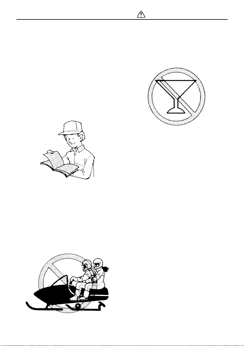
WARNING
PLEASE READ AND UNDERSTAND THIS
MANUAL COMPLETELY BEFORE OPERATING THE SNOWMOBILE.
NOTE:
● Yamaha continually seeks advancements
in product design and quality. Therefore,
while this manual contains the most current
product information available at the time of
printing, there may be minor discrepancies
between your snowmobile and this manual.
If there is any question concerning this
manual, please consult a Yamaha dealer.
● This manual should be considered a per-
manent part of this snowmobile and should
remain with the snowmobile when resold.
EWS00020
WARNING
Failure to follow WARNING instructions
could result in severe injury or death
to the
snowmobile operator, a bystander, or a
person inspecting or repairing the snowmobile.
ECS00010
CAUTION:
A CAUTION indicates special precautions
that must be taken to avoid damage to the
snowmobile.
NOTE:
A NOTE provides key information to make
procedures easier or clearer.
Particularly important information is distinguished in this manual by the following notations.
The Safety Alert Symbol means ATTENTION! BECOME ALERT! YOUR SAFETY IS
INVOLVED!

Contents
Safety information ............................ 1
Location of the important labels ..... 4
Description ...................................... 12
Control functions ............................ 14
Main switch .................................. 14
Throttle lever ................................ 14
Engine overheating prevention
system ....................................... 14
Throttle override system
(T.O.R.S.) .................................. 14
Speedometer unit ......................... 16
High beam indicator light .............. 17
Low coolant temperature indicator
light ............................................ 17
Knock control system “KCS”
indicator light ............................. 17
Drive “D” and reverse “R” indicator
lights .......................................... 18
Fuel meter and grip/thumb
warmer level indicator ............... 18
Fuel level warning indicator .......... 19
Oil level warning indicator ............ 20
Coolant temperature warning
indicator ..................................... 20
Self-diagnosis device ................... 20
Drive select switch ....................... 21
Engine stop switch ....................... 21
Headlight beam switch
“LIGHTS” ................................... 22
Grip/thumb warmer adjustment
switch ........................................ 22
Auxiliary DC jack
(PZ50MP / PZ50VT) .................. 22
Brake lever ................................... 23
Parking brake lever ...................... 23
Shroud latches
(PZ50MP / PZ50VT) .................. 23
Shroud and covers ....................... 24
Drive guard ................................... 25
V-belt holder
(PZ50MP / PZ50VT) ................. 25
Passenger grip warmer switch
(PZ50VT) .................................. 26
Backrest
[PZ50MP (FIN)(SWE)(RUS) /
PZ50VT] .................................... 26
Storage pouch .............................. 26
Rear carrier
(PZ50MP / PZ50VT) ................. 27
Tow hitch [PZ50MP (CAN)(RUS) /
PZ50VT (CAN)] ......................... 28
Fuel .............................................. 28
Suspension .................................. 29
Pre-operation checks ..................... 37
Pre-operation check list ............... 37
Operation ......................................... 39
Starting the engine ....................... 39
Break-in ........................................ 39
Riding your snowmobile ............... 40
Maximizing drive track life ............ 43
Strap (PZ50MT) ........................... 44
Driving .......................................... 44
Stopping the engine ..................... 45
Transporting ................................. 46
Periodic maintenance ..................... 47
Periodic maintenance chart for
the emission control system ..... 47
General maintenance and
lubrication chart ........................ 48
Tool kit ......................................... 50
Removing and installing the
shroud and covers .................... 50
Checking the spark plugs ............. 53
Adjusting the engine idling
speed ........................................ 54
Adjusting the throttle cable free
play (PZ50RT / PZ50GT /
PZ50MT) ................................... 55

Contents
Checking the throttle cable free
play (PZ50MP / PZ50VT) .......... 55
Checking the throttle override
system (T.O.R.S.) ..................... 55
Checking the air filter ................... 56
High-altitude settings .................... 57
Valve clearance ............................ 57
Engine oil and oil filter cartridge ... 57
Cooling system ............................. 61
V-belt ............................................ 62
Drive chain housing ...................... 64
Brake and parking brake .............. 66
Skis and ski runners ..................... 68
Steering system ........................... 68
Drive track and slide runners ....... 69
High-profile pattern drive track ..... 72
Lubrication .................................... 72
Replacing a headlight bulb ........... 73
Adjusting the headlight beams ..... 74
Fittings and fasteners ................... 74
Battery .......................................... 74
Replacing a fuse .......................... 74
Troubleshooting ............................. 77
Storage ............................................ 80
Specifications ................................. 82
Consumer information.................... 85
Identification number records ....... 85
WARRANTY.................................. 85
Safety information
ESU10191
When you ride your snowmobile, you must
know and use the following for your safety.
Severe injury or death may result if you ignore
any of the following.
Before operating
1. Read the Owner’s Manual and all labels
before operating this snowmobile. Become familiar with all of the operating
controls and their function. Consult a
Yamaha dealer about any control or func-
tion you do not understand.
2. This snowmobile was not manufactured
for use on public streets, roads, or highways. Such use is prohibited by law, and
you could collide with another vehicle.
3. PZ50RT, PZ50GT, PZ50MT and
PZ50MP (CAN) are designed to carry the
OPERATOR ONLY.
Passengers are prohibited. Carrying a
passenger can cause loss of control.
4. Do not operate the snowmobile after
drinking alcohol or taking drugs. Your
ability to operate the snowmobile is reduced by the influence of alcohol or
drugs.
5. For safety and proper care of the snowmobile, always perform the pre-operation
checks on page 37 before starting the engine. Check the throttle, brake, and steering for proper operation every time before
starting the engine. Make sure that the
throttle lever moves freely and it returns
to the home position when it is released.
6. Apply the parking brake before starting
the engine. Never drive the snowmobile
with the parking brake applied. This may
overheat the brake disc and reduce braking ability.
7. Do not allow anyone to stand behind the
snowmobile when starting, inspecting, or
adjusting the snowmobile. A broken
track, track fittings, or debris thrown by
the track could be dangerous to the operator or bystanders.
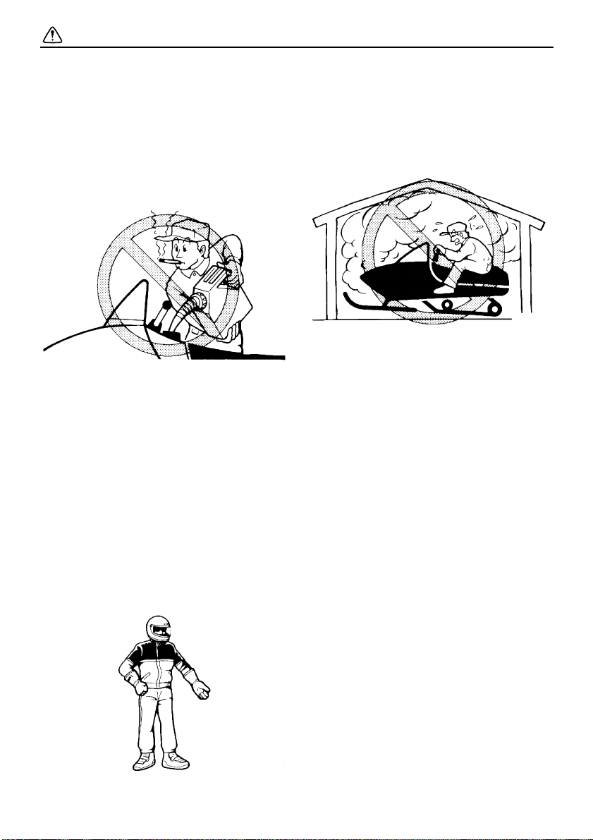
8. Handle fuel with care; it is HIGHLY
FLAMMABLE.
● Never add fuel when the engine is run-
ning or hot. Allow the engine to cool for
several minutes after running.
● Use an approved fuel container.
1
Safety information
● Fill the fuel tank outdoors with extreme
care. Never remove the fuel cap indoors. Never fill the fuel tank indoors.
● Never refuel while smoking or in the vi-
cinity of an open flame.
● Make sure that the fuel tank cap is
closed securely after refueling. Wipe
up any spilled fuel immediately.
9. If you swallow some gasoline, inhale a lot
of gasoline vapor, or get some gasoline
into your eyes, see your doctor immediately. If any gasoline spills on your skin or
clothing, immediately wash your skin with
soap and water, and change your
clothes.
10. Wear protective clothing. Wear an approved helmet, and a face shield or goggles. Also, wear a good quality
snowmobile suit, boots, and a pair of
gloves or mittens that will permit use of
your thumbs and fingers for operation of
the controls.
Operation
1. Do not run the engine indoors, except
when starting the engine to transport the
snowmobile in or out of the building.
Open the outside doors; exhaust fumes
are dangerous.
2. Be careful where you ride. There may be
obstacles hidden beneath the snow. Stay
on established trails to minimize your exposure to hazards. Ride slowly and cautiously when you ride off of established
trails. Hitting a rock or stump, or running
into wires could cause an accident and
injury.
3. This snowmobile is not designed for use
on surfaces other than snow or ice. Use
on dirt, sand, grass, rocks, or bare pavement may cause loss of control and may
damage the snowmobile.
4. Avoid operating on glare ice, or on snow
which has a lot of dirt or sand mixed in.
Operation under such conditions will
damage or result in rapid wear of ski runners, drive track, slide runners, and drive
sprockets.
5. Always ride with other snowmobilers
when going on a ride. You may need help
if you run out of fuel, have an accident, or
damage your snowmobile.
6. Many surfaces such as ice and hardpacked snow require much longer stopping distances. Be alert, plan ahead and
2

begin decelerating early. The best braking method on most surfaces is to release
the throttle and apply the brake gently—
not suddenly.
Maintenance and storage
1. When laying the snowmobile on its side
for maintenance, use a suitable stand to
keep it level.
2. Do not leave the snowmobile on its left
side for an extended period of time. Fuel
may leak out from the fuel breather hose.
3. Modifications made to the snowmobile
not approved by Yamaha, or the removal
of original equipment may render your
snowmobile unsafe for use that may
cause severe personal injury. Modifications may also make the snowmobile illegal to use.
4. Never store the snowmobile with fuel in
the fuel tank inside a building where ignition sources are present such as hot water and space heaters, an open flame,
sparks, clothes dryers, and the like. Allow
the engine to cool off before storing the
snowmobile in an enclosed space.
5. Always refer to the “STORAGE” section
on page 80 if the snowmobile is to be
stored for an extended period.
6. Maintain or replace safety and instruction
labels, as necessary.
Safety information
3
Safety information
ESU12671
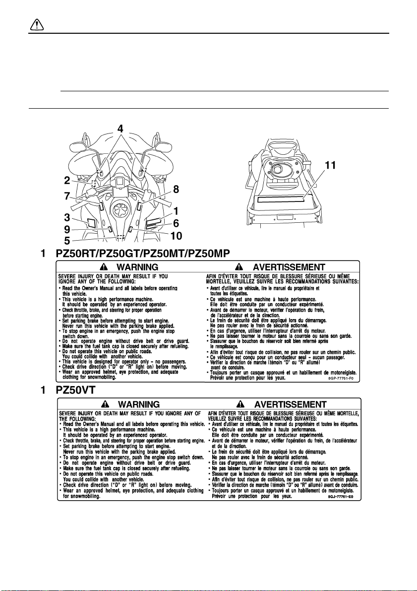
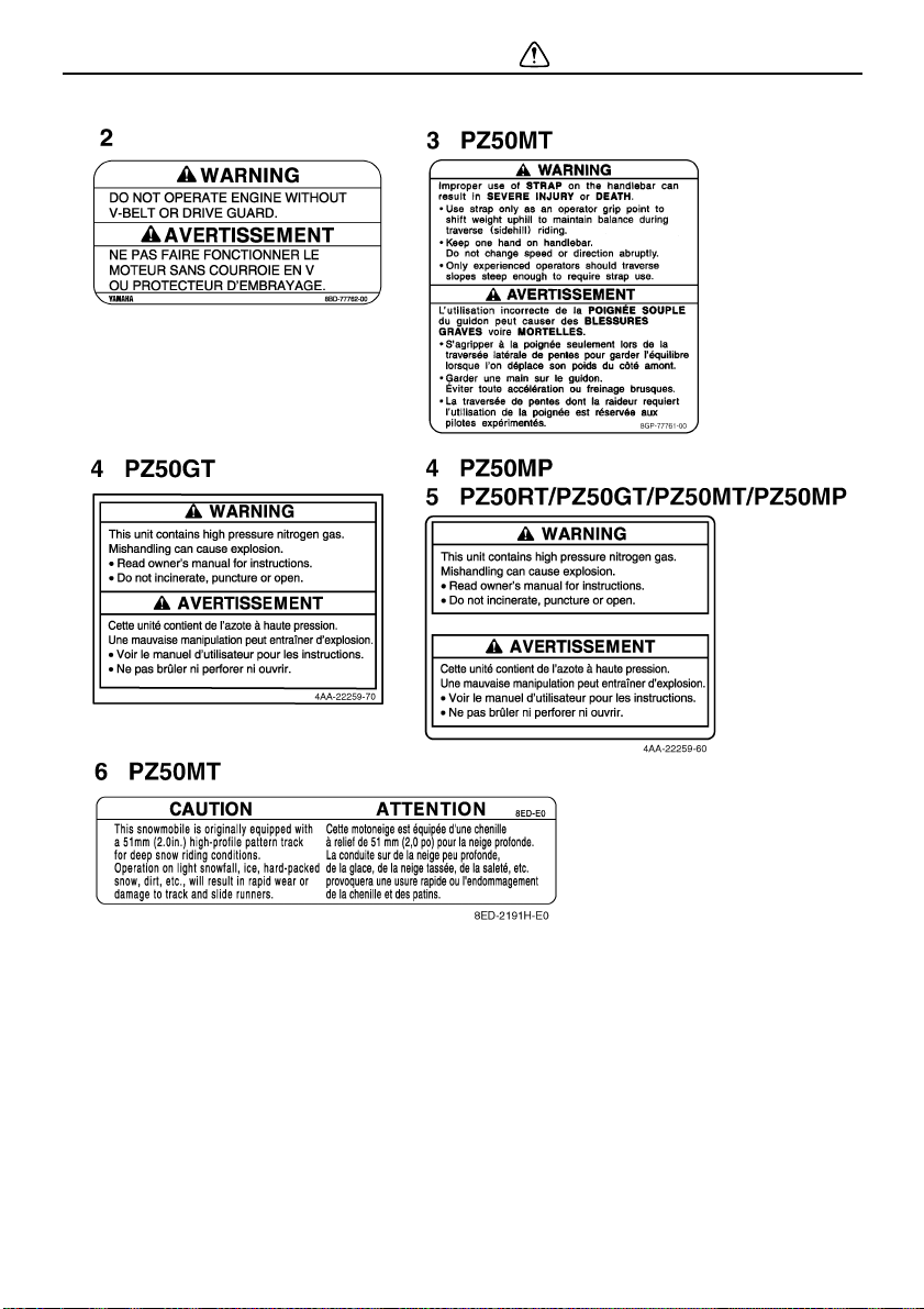
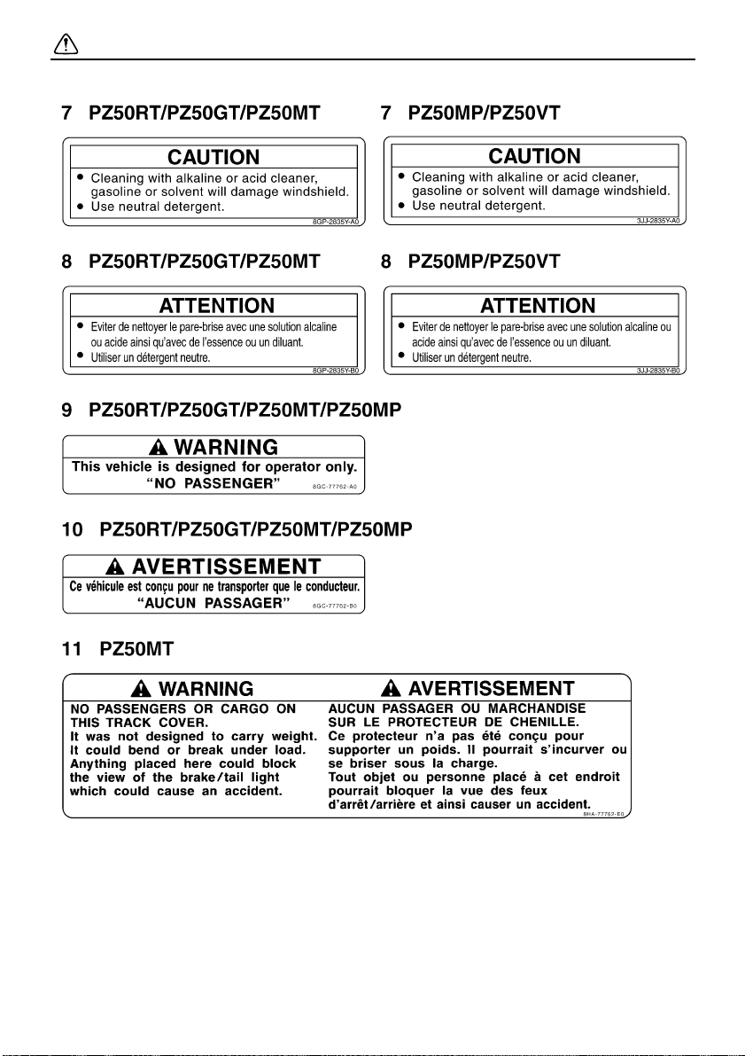
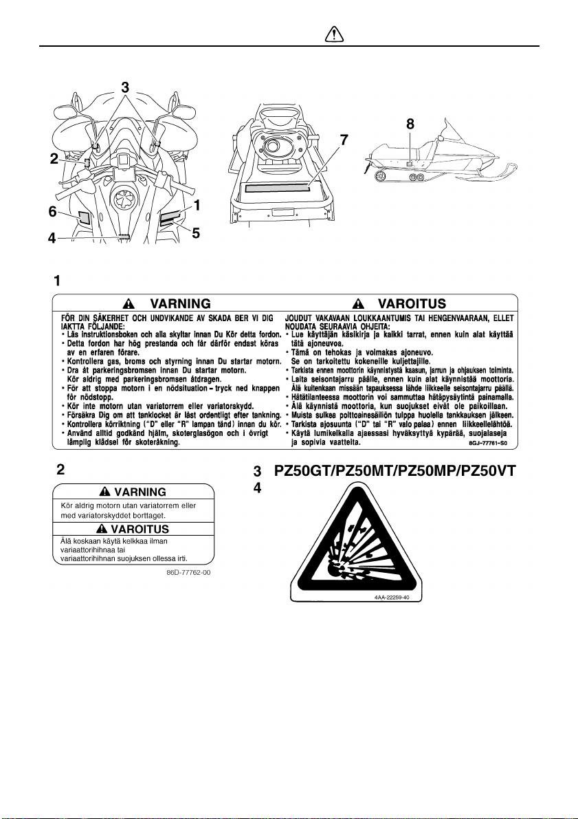
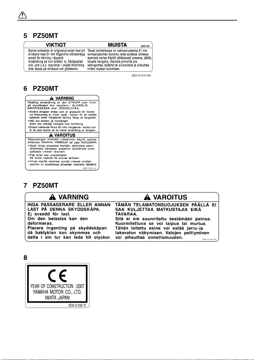
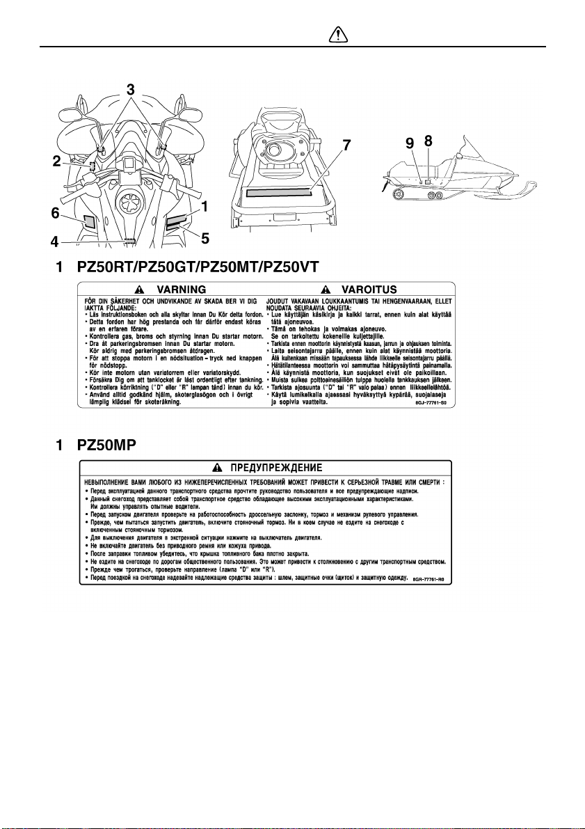
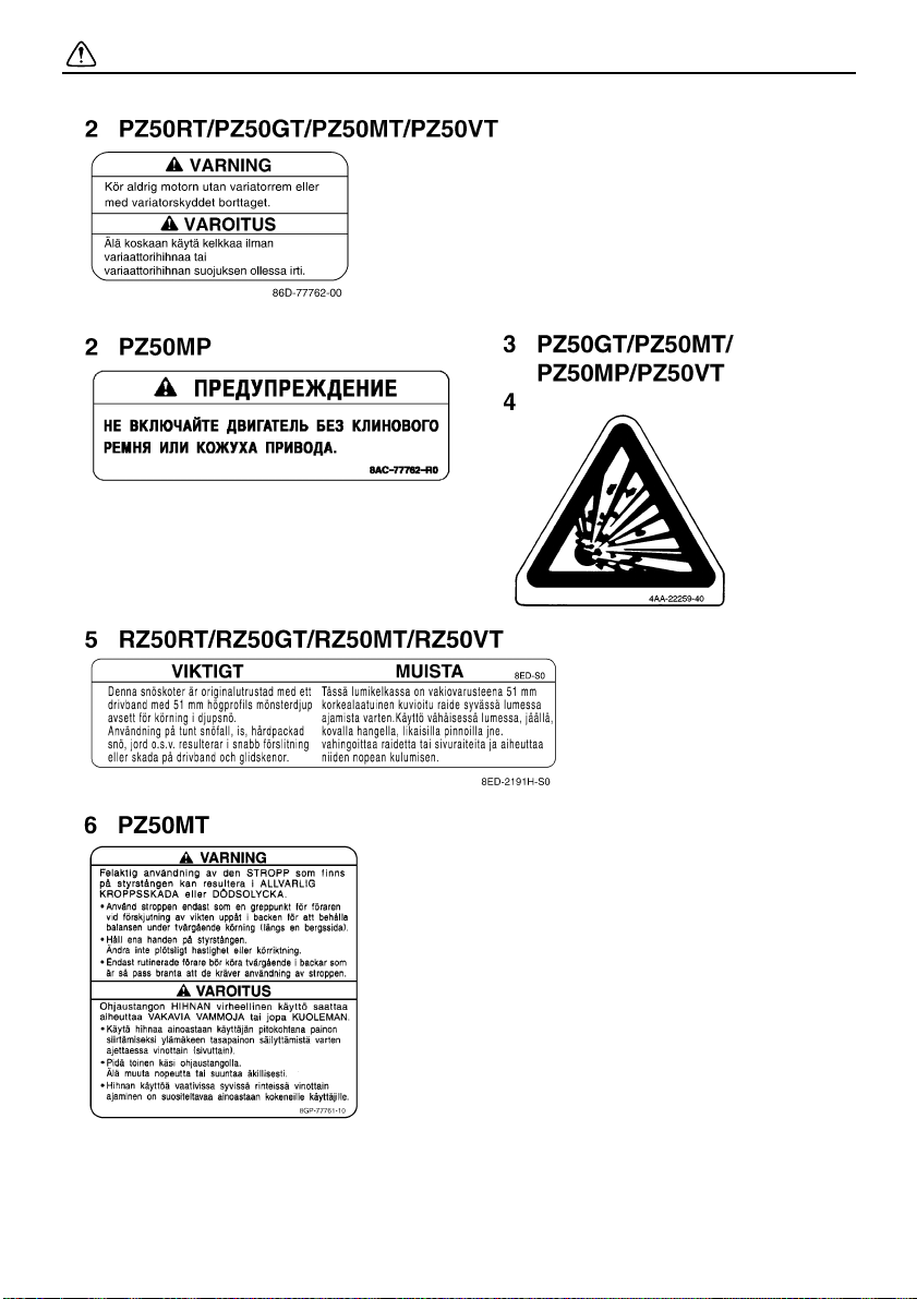
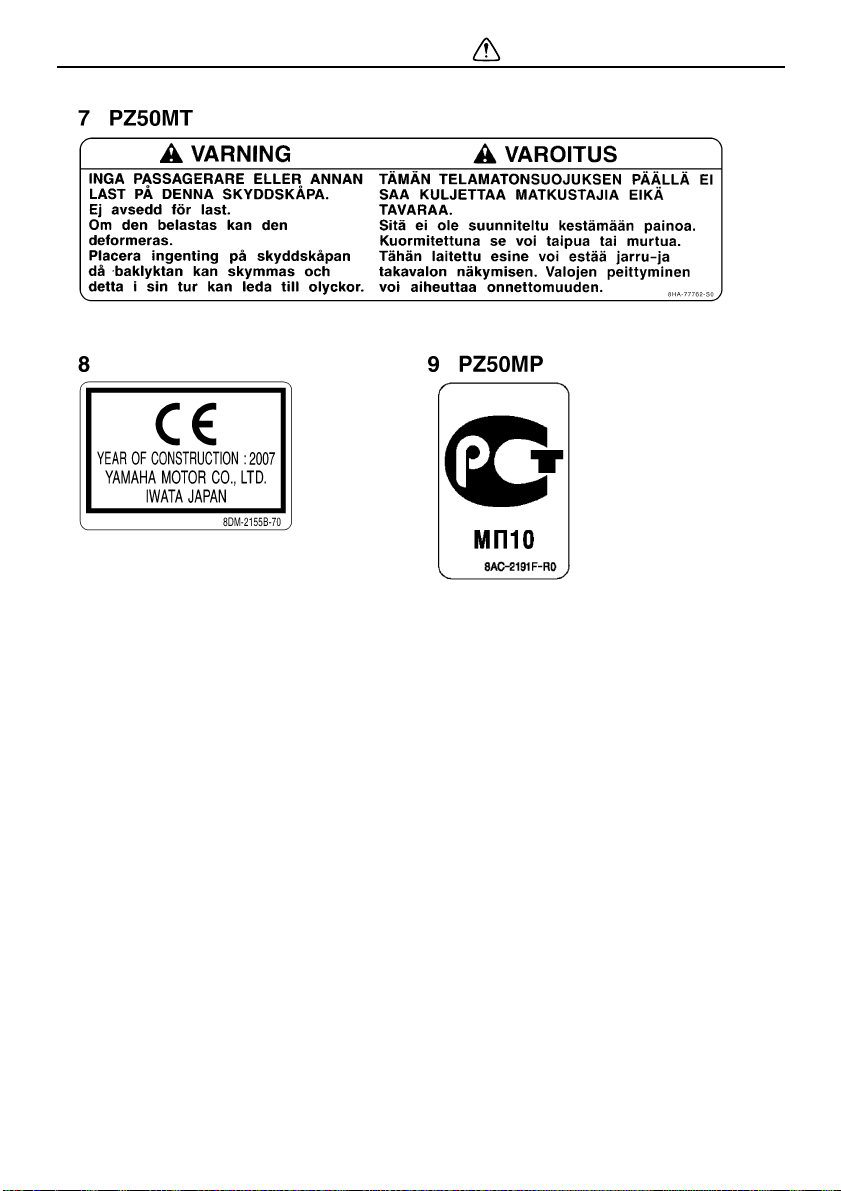
Location of the important labels
Please read the following labels carefully before operating this snowmobile.
NOTE:
Maintain or replace safety and instruction labels, as necessary.
For CANADA
4
Safety information
5
Safety information
6
For EUROPE
Safety information
7
Safety information
8
For RUSSIA
Safety information
9
Safety information
10
Safety information
11
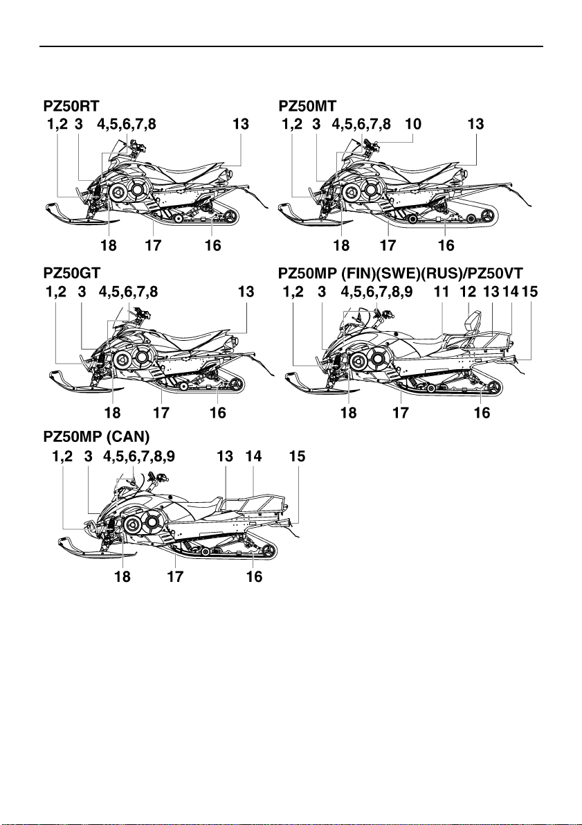
Description
ESU10260
1. Storage pouch
2. Tool kit
3. Air filter
4. Oil filler cap
5. Battery
6. Main fuse
7. Fuse box
8. Coolant reservoir
9. V-belt holder (PZ50MP / PZ50VT)
10. Strap (PZ50MT)
11. Passenger grip warmer switch (PZ50VT)
12
12. Backrest [PZ50MP (FIN)(SWE)(RUS) /
PZ50VT]
13. Tail/brake light
14. Rear carrier (PZ50MP / PZ50VT)
15. Tow hitch [PZ50MP (CAN)(RUS) / PZ50VT
(CAN)]
16. Slide rail suspension
17. Drive track
18. Idle adjusting screw
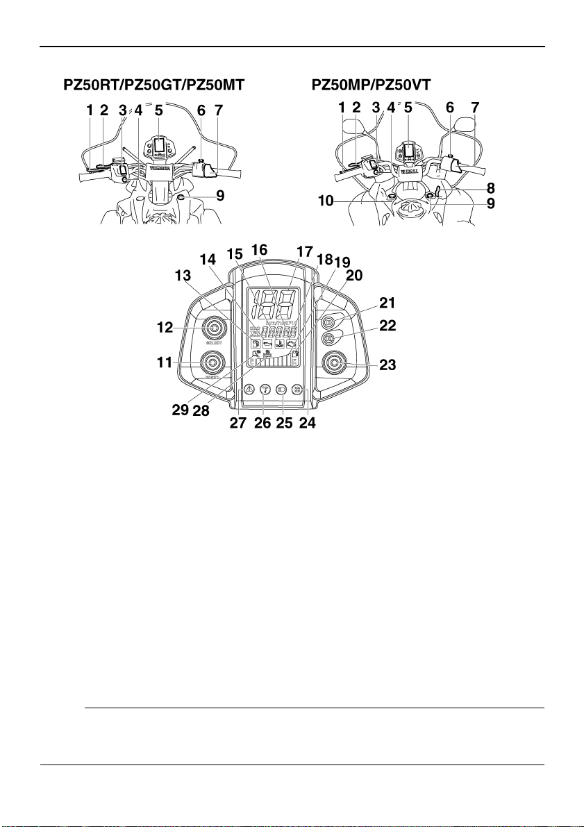
Description
1. Brake lever
2. Parking brake lever
3. Grip/thumb warmer adjustment switch
4. Headlight beam switch
5. Speedometer unit
6. Engine stop switch
7. Throttle lever
8. Shroud latch (PZ50MP / PZ50VT)
9. Main switch
10. Auxiliary DC jack (PZ50MP / PZ50VT)
11. “RESET” button
12. “SELECT” button
13. Fuel level warning indicator
14. Oil level warning indicator
15. Coolant temperature warning indicator
16. Self-diagnosis warning indicator
17. Speedometer
18. Odometer/tripmeter/engine speed meter
19. Fuel meter and grip/thumb warmer level indicator
20. Fuel meter indicator
21. Drive “D” indicator light
22. Reverse “R” indicator light
23. Drive select switch
24. Knock control system “KCS” indicator light
25. High beam indicator light
26. Low coolant temperature indicator light
27. Warning light
28. Grip warmer indicator
29. Thumb warmer indicator
NOTE:
● The snowmobile you have purchased may differ slightly from those shown in the figures of
this manual.
● Design and specifications are subjected to change without notice.
13
Control functions
ESU10291
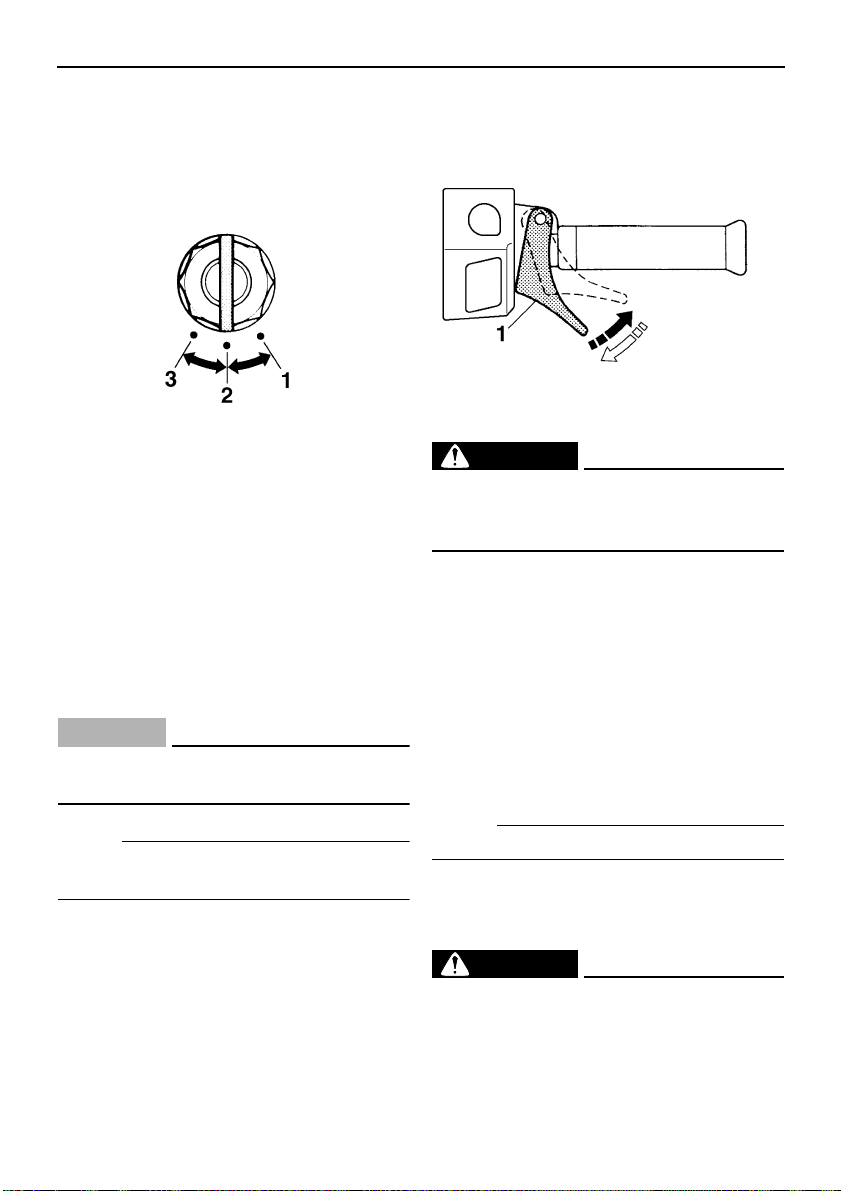
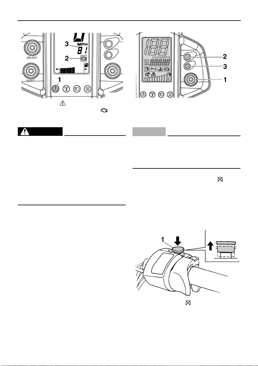
Main switch
The main switch controls the ignition and
lighting systems. The various positions are
described below.
1. Off
2. On
3. Start
Off
The ignition circuit is switched off.
The key can be removed only in this position.
On
The ignition circuit is switched on.
Start
The starting circuit is switched on.
The starter motor cranks the engine.
ECS00020
CAUTION:
Release the switch immediately after the
engine starts.
the throttle is spring-loaded, the snowmobile
will decelerate, and the engine will return to
idle when it is released.
1. Throttle lever
EWS00030
WARNING
Check the throttle, brake, and steering for
proper operation before starting the engine. (See page 37.)
ESU10321
Engine overheating prevention
system
This model is equipped with a system, which
prevents overheating when the engine is
idling.
When the engine has been idling for 3 minutes or longer and the coolant temperature
has risen above 100 °C (212 °F), the engine
automatically stops to prevent overheating.
NOTE:
The headlights and taillight come on after the
engine is started.
ESU10310
Throttle lever
Once the engine is running cleanly, squeezing the throttle lever will increase the engine
speed and cause engagement of the drive
system. Regulate the speed of the snowmobile by varying the throttle position. Because
14
NOTE:
The engine can be started after it stops.
ESU10344
Throttle override system
(T.O.R.S.)
EWS00040
WARNING
● If the T.O.R.S. is activated, make sure
that the cause of the malfunction has
been corrected and that the engine can
be operated without a problem before
restarting the engine.
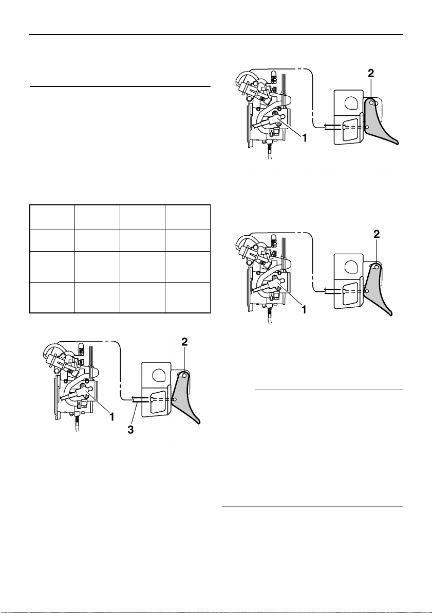
Control functions
● Be sure to use the specified spark plug
and spark plug cap. Otherwise, the
T.O.R.S. will not work properly.
If the throttle bodies or throttle cable malfunctions during operation, the T.O.R.S. will operate when the throttle lever is released.
The T.O.R.S. is designed to override the fuel
injection and limit the engine speed to less
than the clutch engagement speed if the throttle valves fail to return to the idle position
when the throttle lever is released. (See page
82 for the clutch engagement speed.)
Idling /
starting
Throttle
switch
Throttle
position
sensor
Engine Run Run
Off On Off
Closed Open Open
Running Trouble
T. O. R . S .
will oper-
ate.
Idling / starting
Running
1. Throttle position sensor (throttle valve open
position)
2. Throttle switch (on)
Trouble
1. Throttle position sensor (throttle valve open
position)
2. Throttle switch (off)
1. Throttle position sensor (throttle valve
closed position)
2. Throttle switch (off)
3. Throttle cable
NOTE:
● When the T.O.R.S. is activated, the warn-
ing light and self-diagnosis warning indicator will flash, and the two-digit code “84” will
flash in the meter display.
● The T.O.R.S. monitors the condition of the
throttle position sensor, speedometer assembly, and speed sensor, and will operate
if any of the monitored items is disconnected or is malfunctioning.
15
Control functions
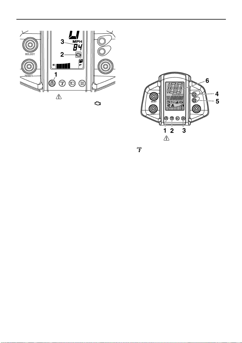
1. Warning light “”
2. Self-diagnosis warning indicator “”
3. Two-digit code “84”
ESU10390
Speedometer unit
The speedometer unit is equipped with the
following:
● a digital speedometer (which shows the
riding speed)
● an odometer (which shows the total dis-
tance traveled)
● a tripmeter (which shows the distance trav-
eled since it was last set to zero)
● an engine speed meter (which shows the
engine speed; not for use while riding)
● warning indicators (which show self-diag-
nosis, coolant temperature, fuel level, and
oil level warnings)
● indicator lights (which show high beam, low
coolant temperature, transmission position,
and knock control system conditions)
● a warning light (which shows warnings to-
gether with the warning indicators)
● a fuel meter (which shows the fuel remain-
ing in the fuel tank)
● a grip/thumb warmer level indicator (which
shows the grip warmer or the thumb warm-
er level)
After the main switch is turned on, the warning
light, the low coolant temperature indicator
light, the knock control system “KCS” indica-
tor light, the drive “D” indicator light, the reverse “R” indicator light, and all segments of
the meter display turn on and off once.
The grip warmer level is initially displayed for
5 seconds, then the display switches to the
fuel meter.
1. Warning light “”
2. Low coolant temperature indicator light
“”
3. Knock control system “KCS” indicator light
4. Drive “D” indicator light
5. Reverse “R” indicator light
6. Meter display
Odometer, tripmeter, and engine
speed meter modes
Pushing the “SELECT” button switches the
display between the odometer mode “ODO”,
tripmeter mode “TRIP”, and engine speed
meter mode “r/min”.
To reset the tripmeter, push the “RESET” button for at least 1 second while the tripmeter is
displayed.
16
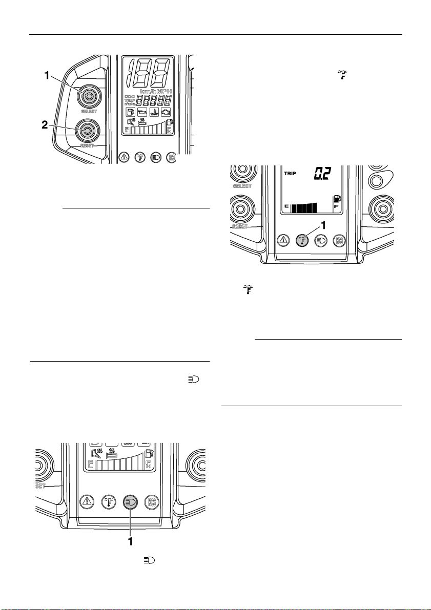
1. “SELECT” button
2. “RESET” button
NOTE:
● To switch the speedometer, odometer, and
tripmeter displays between kilometers and
miles, select the odometer mode “ODO”,
and then push the “SELECT” button for at
least 10 seconds while the snowmobile is
stopped.
● Use the engine speed meter only when
checking the snowmobile and performing
basic maintenance. The engine speed
meter should not be used while riding the
snowmobile since the reading will vary from
the actual engine speed.
ESU10410
High beam indicator light “”
The high beam indicator light comes on when
the high beams of the headlights are switched
on. (See page 22 for headlight beam switch
operation.)
Control functions
ESU10471
Low coolant temperature indi-
cator light “”
The low coolant temperature indicator light
comes on when the coolant temperature is
low and informs the rider that the snowmobile
should be warmed up. After the engine is
started, warm it up until the indicator light
goes off.
1. Low coolant temperature indicator light
“”
The snowmobile can be operated normally after the indicator light goes off.
NOTE:
Operate the snowmobile at low speeds when
the low coolant temperature indicator light is
on. If the engine speed is too high, maximum
engine speed is reduced to protect the engine.
ESU10500
Knock control system “KCS”
indicator light
This snowmobile is equipped with a system
which detects engine knocking in order to protect the engine from damage.
The knock control system “KCS” indicator
light comes on if knocking is detected, then
flashes if the knocking increases.
1. High beam indicator light “”
17
Control functions
1. Knock control system “KCS” indicator light 1. Drive “D” indicator light
After the knocking has stopped, the knock
control system “KCS” indicator light goes off.
ECS00030
CAUTION:
● If the knock control system “KCS” indi-
cator light comes on, the fuel tank may
not have been filled with the recom-
mended fuel. Reduce the engine speed
to 6000 r/min or less. As soon as possi-
ble, stop the engine, let it cool sufficient-
ly, and then drain the fuel and refuel with
the recommended fuel.
● If the knock control system “KCS” indi-
cator light is flashing, have a Yamaha
dealer inspect the snowmobile as soon
as possible.
2. Reverse “R” indicator light
The snowmobile can be shifted into drive or
reverse by pushing the drive select switch.
(See page 21 for drive select switch operation.)
ESU10431
Fuel meter and grip/thumb
warmer level indicator
The fuel meter and grip/thumb warmer level
indicator have eight segments which show
the amount of fuel remaining in the fuel tank,
the grip warmer level, or the thumb warmer
level.
NOTE:
To help prevent knocking, use premium unleaded gasoline only. (See page 28 for more
details.)
ESU10490
Drive “D” and reverse “R” indi-
cator lights
These indicator lights show whether the
snowmobile is shifted into drive or reverse.
The drive “D” indicator light comes on when
the transmission is in drive (forward).
The reverse “R” indicator light comes on when
the transmission is in reverse.
18
1. Fuel meter and grip/thumb warmer level indicator
Fuel meter
The display segments of the fuel meter disappear towards “E” (Empty) as the fuel level decreases. When only one segment is left near
“E”, the fuel level warning indicator and the
warning light come on.
Control functions
1. Fuel level warning indicator “”
2. Warning light “”
If the fuel level warning indicator and the
warning light come on, refuel as soon as possible.
NOTE:
The snowmobile must be stopped on a level
surface to obtain an accurate fuel meter reading, since the reading changes according to
the movement and inclination of the snowmobile.
Grip/thumb warmer level indicator
When the grip warmer side of the grip/thumb
warmer adjustment switch is pressed, the grip
warmer indicator comes on and the display
switches to the grip warmer level.
When the thumb warmer side of the
grip/thumb warmer adjustment switch is
pressed, the thumb warmer indicator comes
on and the display switches to the thumb
warmer level.
1. Grip/thumb warmer adjustment switch
1. Grip warmer indicator “”
2. Thumb warmer indicator “”
NOTE:
● The grip/thumb warmer level is displayed
for 5 seconds after releasing the grip/thumb
warmer adjustment switch, then the display
switches to the fuel meter.
● When the engine is started, the grip/thumb
warmer levels are set to the levels selected
when the engine is stopped.
ESU10450
Fuel level warning indicator “”
The fuel level warning indicator indicates a
malfunctioning sensor, disconnected coupler,
broken lead, or short circuit when detected by
the self-diagnosis device of the snowmobile.
The fuel level warning indicator, warning light,
and all segments of the fuel meter warn the
rider of the above problems by flashing continuously.
19
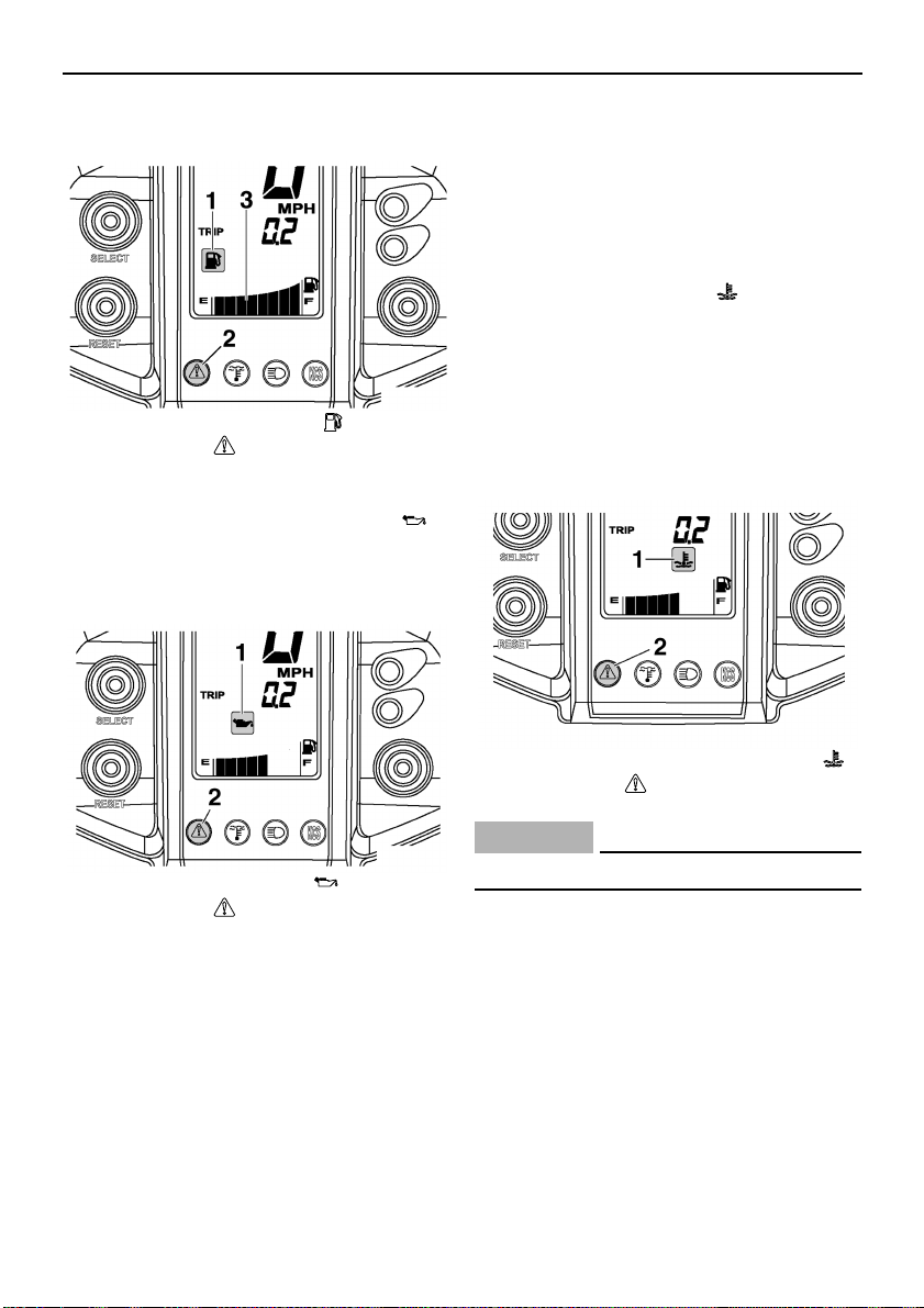
Control functions
When this occurs, have a Yamaha dealer inspect the snowmobile as soon as possible.
1. Fuel level warning indicator “”
2. Warning light “”
3. Fuel meter
ESU10460
Oil level warning indicator “”
The oil level warning indicator and the warning light come on when the engine oil level is
low.
If the oil level warning indicator and the warning light do not go off, check the engine oil level in the oil tank (see page 57 for engine oil
level checking procedures), and add engine
oil if necessary.
ESU10511
Coolant temperature warning
indicator “”
If the engine overheats, the coolant temperature warning indicator and the warning light
come on. When this occurs, stop the engine
immediately and allow the engine to cool
down, and then check the coolant level in the
coolant reservoir. (See page 61 for checking
procedures.)
1. Oil level warning indicator “”
2. Warning light “”
If the oil level warning indicator and the warning light come on, place the snowmobile on a
level surface and allow it to idle for one
minute.
If the oil level warning indicator and the warning light go off, the engine oil level is sufficient,
however it is getting low. Add engine oil as
soon as possible.
20
1. Coolant temperature warning indicator “”
2. Warning light “”
ECS00040
CAUTION:
Do not operate the engine if it overheats.
ESU12680
Self-diagnosis device
This model is equipped with a self-diagnosis
device for various electrical circuits.
If any of those circuits are defective, the warning light and the self-diagnosis warning indicator will flash, and a two-digit error code will
flash slowly in the tripmeter/odometer display.
Control functions
1. Warning light “”
2. Self-diagnosis warning indicator “”
3. Two-digit error code
EWS00650
WARNING
If the self-diagnosis warning indicator and
warning light flash continuously, and an
error code is displayed during operation,
there may be some problem with an electrical circuit, couplers, etc.
Note the error code, and then have a
Yamaha dealer inspect the snowmobile as
soon as possible in order to avoid engine
damage.
ESU10540
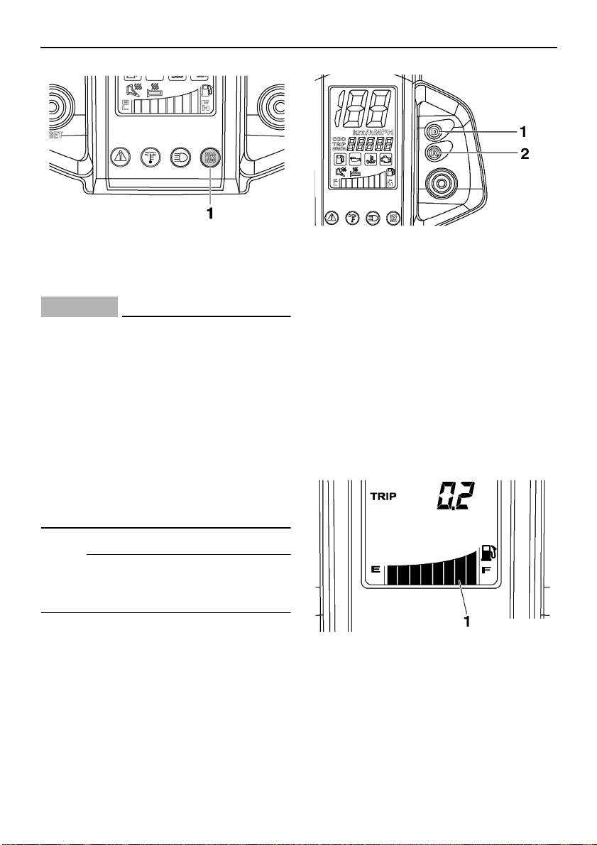
Drive select switch
The drive select switch is used to shift the
snowmobile into drive or reverse. After coming to a complete stop, press the drive select
switch.
The drive “D” indicator light comes on when
the transmission is in drive (forward).
The reverse “R” indicator light comes on when
the transmission is in reverse.
1. Drive select switch
2. Drive “D” indicator light
3. Reverse “R” indicator light
ECS00050
CAUTION:
Do not shift from drive to reverse or from
reverse to drive while the snowmobile is
moving. Otherwise, the drive system
could be damaged.
ESU10530
Engine stop switch “”
The engine stop switch is used to stop the engine in an emergency. Simply push the stop
switch to stop the engine. To start the engine,
pull the stop switch and proceed with starting
the engine. (See pages 39 for engine starting
procedures.)
1. Engine stop switch“”
During the first few rides, practice using the
stop switch so that you can react quickly in an
emergency.
21
Control functions
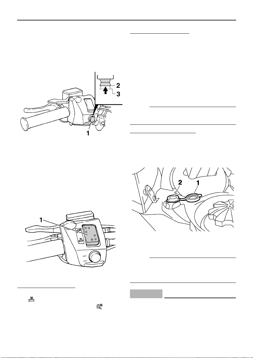
ESU10661
Headlight beam switch
“LIGHTS”
Push the headlight beam switch to change the
headlight to high beam “HI” or to low beam
“LO”.
1. Headlight beam switch “LIGHTS”
2. High beam “HI”
3. Low beam “LO”
ESU10670
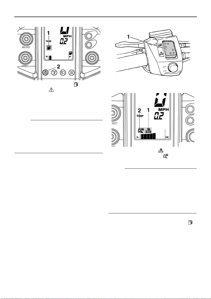
Grip/thumb warmer adjustment
switch
The grip/thumb warmer adjustment switch
controls the electrically heated handlebar
grips and throttle lever.
To lower the temperature
Continue to press the switch until the temperature level returns to the minimum level, and
then raise the temperature to the desired level.
ESU10690
Auxiliary DC jack (PZ50MP /
PZ50VT)
The auxiliary DC jack is located in the front
panel and can be used for accessories.
NOTE:
The auxiliary DC jack cannot be used if the
engine is not running.
To use the auxiliary DC jack
1. Start the engine.
2. Open the auxiliary DC jack cap, and then
insert the accessory power plug into the
jack.
1. Grip/thumb warmer adjustment switch
To raise the temperature
To raise the grip warmer temperature, press
the “” side of the switch. To raise the thumb
warmer temperature, press the “” side of
the switch.
22
1. Auxiliary DC jack cap
2. Auxiliary DC jack
NOTE:
After using the auxiliary DC jack, be sure to
remove the accessory power plug from the
jack and close the auxiliary DC jack cap.
ECS00120
CAUTION:
● Do not use accessories requiring more
than the maximum rated capacity for the
auxiliary DC jack. This may overload the
circuit and cause the fuse to blow. (See
page 74 for the specified amperage.)
 Loading...